WO2013172391A1 - Multi-tenant system, switch, controller, and packet transfer method - Google Patents
Multi-tenant system, switch, controller, and packet transfer method Download PDFInfo
- Publication number
- WO2013172391A1 WO2013172391A1 PCT/JP2013/063603 JP2013063603W WO2013172391A1 WO 2013172391 A1 WO2013172391 A1 WO 2013172391A1 JP 2013063603 W JP2013063603 W JP 2013063603W WO 2013172391 A1 WO2013172391 A1 WO 2013172391A1
- Authority
- WO
- WIPO (PCT)
- Prior art keywords
- packet
- switch
- address
- tenant
- encapsulated
- Prior art date
Links
Images


Classifications
-
- H—ELECTRICITY
- H04—ELECTRIC COMMUNICATION TECHNIQUE
- H04L—TRANSMISSION OF DIGITAL INFORMATION, e.g. TELEGRAPHIC COMMUNICATION
- H04L45/00—Routing or path finding of packets in data switching networks
- H04L45/74—Address processing for routing
-
- H—ELECTRICITY
- H04—ELECTRIC COMMUNICATION TECHNIQUE
- H04L—TRANSMISSION OF DIGITAL INFORMATION, e.g. TELEGRAPHIC COMMUNICATION
- H04L12/00—Data switching networks
- H04L12/28—Data switching networks characterised by path configuration, e.g. LAN [Local Area Networks] or WAN [Wide Area Networks]
- H04L12/46—Interconnection of networks
- H04L12/4633—Interconnection of networks using encapsulation techniques, e.g. tunneling
-
- H—ELECTRICITY
- H04—ELECTRIC COMMUNICATION TECHNIQUE
- H04L—TRANSMISSION OF DIGITAL INFORMATION, e.g. TELEGRAPHIC COMMUNICATION
- H04L41/00—Arrangements for maintenance, administration or management of data switching networks, e.g. of packet switching networks
- H04L41/08—Configuration management of networks or network elements
- H04L41/0803—Configuration setting
- H04L41/0806—Configuration setting for initial configuration or provisioning, e.g. plug-and-play
- H04L41/0809—Plug-and-play configuration
-
- H—ELECTRICITY
- H04—ELECTRIC COMMUNICATION TECHNIQUE
- H04L—TRANSMISSION OF DIGITAL INFORMATION, e.g. TELEGRAPHIC COMMUNICATION
- H04L41/00—Arrangements for maintenance, administration or management of data switching networks, e.g. of packet switching networks
- H04L41/08—Configuration management of networks or network elements
- H04L41/0876—Aspects of the degree of configuration automation
- H04L41/0886—Fully automatic configuration
-
- H—ELECTRICITY
- H04—ELECTRIC COMMUNICATION TECHNIQUE
- H04L—TRANSMISSION OF DIGITAL INFORMATION, e.g. TELEGRAPHIC COMMUNICATION
- H04L41/00—Arrangements for maintenance, administration or management of data switching networks, e.g. of packet switching networks
- H04L41/34—Signalling channels for network management communication
- H04L41/342—Signalling channels for network management communication between virtual entities, e.g. orchestrators, SDN or NFV entities
-
- H—ELECTRICITY
- H04—ELECTRIC COMMUNICATION TECHNIQUE
- H04L—TRANSMISSION OF DIGITAL INFORMATION, e.g. TELEGRAPHIC COMMUNICATION
- H04L45/00—Routing or path finding of packets in data switching networks
- H04L45/74—Address processing for routing
- H04L45/745—Address table lookup; Address filtering
-
- H—ELECTRICITY
- H04—ELECTRIC COMMUNICATION TECHNIQUE
- H04L—TRANSMISSION OF DIGITAL INFORMATION, e.g. TELEGRAPHIC COMMUNICATION
- H04L49/00—Packet switching elements
- H04L49/15—Interconnection of switching modules
-
- H—ELECTRICITY
- H04—ELECTRIC COMMUNICATION TECHNIQUE
- H04L—TRANSMISSION OF DIGITAL INFORMATION, e.g. TELEGRAPHIC COMMUNICATION
- H04L61/00—Network arrangements, protocols or services for addressing or naming
- H04L61/09—Mapping addresses
- H04L61/25—Mapping addresses of the same type
- H04L61/2596—Translation of addresses of the same type other than IP, e.g. translation from MAC to MAC addresses
-
- H—ELECTRICITY
- H04—ELECTRIC COMMUNICATION TECHNIQUE
- H04L—TRANSMISSION OF DIGITAL INFORMATION, e.g. TELEGRAPHIC COMMUNICATION
- H04L67/00—Network arrangements or protocols for supporting network services or applications
- H04L67/01—Protocols
- H04L67/10—Protocols in which an application is distributed across nodes in the network
- H04L67/1097—Protocols in which an application is distributed across nodes in the network for distributed storage of data in networks, e.g. transport arrangements for network file system [NFS], storage area networks [SAN] or network attached storage [NAS]
Abstract
Description
[構成の説明]
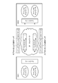
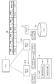
はじめに、本実施形態におけるマルチテナントシステムの構成の説明を行う。図3は、本発明の第1実施形態のマルチテナントシステムの全体図である。実施形態のマルチテナントシステムは、OFC(Open Flow Controller)1、第1のOFS(Open Flow Switch)2-1、第2のOFS2-2、サーバ装置3、ブリッジ5、及びSAN6を備える。サーバ装置3は、VM(Virtual Machine)4-1、及びVM4-2を備える。図3の構成例は、説明のために、簡易な構成となっているが、マルチテナントシステムに接続されている装置は、任意の台数でよい。また、本実施形態では、ユーザに割り当てられているリソースを、サーバ装置上で動作するVMとして説明しているが、パーソナルコンピュータ等の物理的な端末であってもよい。 (First embodiment)
[Description of configuration]
First, the configuration of the multi-tenant system in the present embodiment will be described. FIG. 3 is an overall view of the multi-tenant system according to the first embodiment of this invention. The multi-tenant system of the embodiment includes an OFC (Open Flow Controller) 1, a first OFS (Open Flow Switch) 2-1, a second OFS 2-2, a
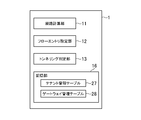
Hyper-Visorのレイヤーで管理され得る。この場合、VMが送信したパケットを受信したOFS2は、Hyper-VisorにそのVMが所属するテナントを問い合わせて、当該パケットにそのテナント識別情報を付加する。 FIG. 8 is an example of the tenant management table 27 according to the first embodiment of this invention. In the tenant management table 27, the MAC address of the device connected to the
次に、本実施形態のマルチテナントシステムにおけるパケット転送方法について説明する。 [Description of operation method]
Next, a packet transfer method in the multi-tenant system of this embodiment will be described.
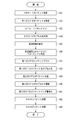
テナントAシステムに属するVM4-1が、識別不能機器であるSAN6に向けてパケットを送信する。なお、図12では、サーバ装置3から第1のOFS2-1へ送信されているパケット(src:VM4-1、dst:SAN6)が、当該パケットに対応している。ここで、「src:VM4-1」は、送信元IPアドレスが、VM4-1に割り当てられているIPアドレスであることを示す。同様に、「dst:SAN6」は、送信先IPアドレスが、SAN6に割り当てられているIPアドレスであることを示す。 (Step S1)
The VM 4-1 belonging to the tenant A system transmits a packet to the
第1のOFS2-1は、ステップS1で送信されたパケットを受信する。第1のOFS2-1は、当該パケットの送信先IPアドレスに対応するMACアドレスと、MACアドレステーブル26を比較する。第1のOFS2-1は、当該MACアドレスが、MACアドレステーブル26で管理されていない場合には、当該MACアドレスに対応する装置が、他のOFS2に接続されていると判断する(あるいは、当該MACアドレスに対応する装置が、第1のOFS2-1自身に接続されていないと判断する)。この場合、第1のOFS2-1は、当該パケットをカプセル化する必要があると判断する。本一例において第1のOFS2-1は、当該パケットを参照し、受信パケットの送信先IPアドレスに対応する装置(ここでは一例としてSAN6)が第1のOFS2-1自身に接続されていないと判断する。 (Step S2)
The first OFS 2-1 receives the packet transmitted in step S1. The first OFS 2-1 compares the MAC address corresponding to the destination IP address of the packet with the MAC address table 26. If the MAC address is not managed in the MAC address table 26, the first OFS 2-1 determines that the device corresponding to the MAC address is connected to another OFS 2 (or the It is determined that the device corresponding to the MAC address is not connected to the first OFS 2-1 itself). In this case, the first OFS 2-1 determines that the packet needs to be encapsulated. In this example, the first OFS 2-1 refers to the packet and determines that the device corresponding to the destination IP address of the received packet (here,
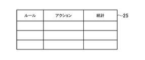
第1のOFS2-1は、受信パケットの転送経路と、当該パケットをカプセル化する際の宛先IPアドレスを、OFC1に問い合わせるため、当該パケットを、OFC1にパケットインする。本一例では、第1のOFS2-1は、ステップS2においてMACアドレステーブル26に基づいてカプセル化の要否を判断し、OFC1に対するカプセル化に必要な情報の問い合わせが必要かどうかを判断した(ステップS2)。なお、第1のOFS2-1は、MACアドレステーブル26を参照せずに、フローテーブル25に、当該パケットを転送するためのフローエントリがない場合に、OFC1に問い合わせが必要であると判断してもよい。 (Step S3)
The first OFS 2-1 inquires the
OFC1は、当該パケットインされたパケットの宛先であるSAN6が接続されているOFS2が、第2のOFS2-2であることを特定する。OFC1は、当該パケットインされたパケットを、第2のOFS2-2まで送信するための往路経路を計算する。 (Step S4)
The OFC1 specifies that the OFS2 to which the SAN6 that is the destination of the packeted packet is connected is the second OFS2-2. The
OFC1が、当該パケットを転送するためのフローエントリを、ステップS4の処理により算出された往路経路上のスイッチに設定する。なお、図12では、説明を簡略化するため、第1のOFS2-1、及び第2のOFS2-2のみを記載しているが、第1のOFS2-1と、第2のOFS2-2の間には、複数のOFS2が存在していてもよい。その場合には、第1のOFS2-1と、第2のOFS2-2の間のOFS2にも、当該フローエントリが設定される。 (Step S5)
The
OFC1は、ステップS3の処理でパケットインされたパケットを、第1のOFS2-1にパケットアウトする。 (Step S6)
The
第1のOFS2-1は、OFC1により設定されたフローエントリに従い、パケットインされたパケット(ステップS2において受信したパケット)を、付加情報によりカプセル化することにより、カプセル化パケットを作成する。当該付加情報は、例えば、L3ヘッダ(送信元IPアドレス:OFS2-1、送信先IPアドレス:OFS2-2)と、テナント識別情報(テナントA)を含む。ここで、「送信元IPアドレス:OFS2-1」は、カプセル化パケットの送信元IPアドレスが、第1のOFS2-1のIPアドレスであることを示す。同様に、「送信先IPアドレス:OFS2-2」は、カプセル化パケットの送信先IPアドレスが、第2のOFS2-2のIPアドレスであることを示す。 (Step S7)
The first OFS 2-1 creates an encapsulated packet by encapsulating the packet-in packet (the packet received in step S 2) with additional information according to the flow entry set by the
第2のOFS2-2は、当該カプセル化パケットを、第1のOFS2-1から受信する。第2のOFS2-2は、当該カプセル化パケットに含まれる付加情報から送信元ゲートウェイである第1のOFS2-1のIPアドレス及びテナント識別情報を抽出するとともに、付加情報を除くパケットのヘッダ情報から送信元VM4-1のIPアドレス及び宛先装置であるSAN6のIPアドレスを抽出し、アドレス変換テーブル29に記録する。又、第2のOFS2-2は、当該カプセル化パケットに含まれるデータの転送に使用する送信元IPアドレス(アドレス変換テーブル29の割当IPアドレス)に、DUMを割り当てる。本一例において、当該カプセル化パケットに対応するアドレス変換テーブル29のレコードは、図12に記載されたアドレス変換テーブル29のようになる。 (Step S8)
The second OFS 2-2 receives the encapsulated packet from the first OFS 2-1. The second OFS 2-2 extracts the IP address and tenant identification information of the first OFS 2-1 that is the transmission source gateway from the additional information included in the encapsulated packet, and from the header information of the packet excluding the additional information. The IP address of the transmission source VM 4-1 and the IP address of the
第2のOFS2-2が、ステップS5の処理により設定されたフローエントリに基づいて、ステップS7の処理で付与された付加情報を除去する。 (Step S9)
The second OFS 2-2 removes the additional information given in the process in step S7 based on the flow entry set in the process in step S5.
第2のOFS2-2は、図12のアドレス変換テーブル29に基づいて、送信元IPアドレスをDUMに変換する。なお、図12の第2のOFS2-2におけるアドレス変換テーブル29では、宛先ポート番号、及び割当ポート番号が使用されていない。このように、宛先IPアドレス、宛先テナント、割当IPアドレス、及び送信元ゲートウェイのみを利用して、パケットの書き換えを行ってもよい。すなわち、第2のOFS2-2は、NAT機能、又はIPマスカレード機能により、パケットを書き換える。例えばOFS2-2は、NAT機能を利用する場合、OFS2-2に管理されている複数のIPアドレスから、送信元VM毎に一意のIPアドレスをDUMとして払い出す。あるいは、OFS2-2は、IPマスカレード機能を利用する場合、OFS2-2に管理されている複数のIPアドレスとポート番号から、送信元VM毎に一意のIPアドレスとポート番号の組み合わせをDUMとして払い出す。 (Step S10)
The second OFS 2-2 converts the transmission source IP address to DUM based on the address conversion table 29 of FIG. Note that the destination port number and the assigned port number are not used in the address conversion table 29 in the second OFS 2-2 in FIG. In this way, packet rewriting may be performed using only the destination IP address, the destination tenant, the assigned IP address, and the source gateway. That is, the second OFS 2-2 rewrites the packet by the NAT function or the IP masquerade function. For example, when using the NAT function, the OFS 2-2 pays out a unique IP address as a DUM for each transmission source VM from a plurality of IP addresses managed by the OFS 2-2. Alternatively, when using the IP masquerade function, OFS2-2 pays a unique IP address and port number combination as a DUM for each source VM from a plurality of IP addresses and port numbers managed by OFS2-2. put out.
第2のOFS2-2は、ステップS9の処理により、送信元IPアドレスが書き換えられたパケットを、SAN6に向けて送信する。 (Step S11)
The second OFS 2-2 transmits the packet in which the transmission source IP address is rewritten to the
SAN6は、ブリッジ5を介して、当該書き換えられたパケットを受信する。なお、SAN6は、ブリッジ5を介さずに第2のOFS2-2に接続されていてもよい。 (Step S12)
The
識別不能機器であるSAN6は、ステップS12において受信したパケットに対するリプライパケットとしてVM4-1に向けてパケットを送信する。なお、図14では、SAN6から、ブリッジ5を介して、第2のOFS2-2へ送信されているパケット(src:SAN6、dst:DUM)が、当該パケットに対応している。 (Step S21)
The
第2のOFS2-2は、受信パケットの宛先IPアドレスがDUMであることから、アドレス変換テーブル29を参照して、送信先IPアドレスの変換を行う。ここでは、第2のOFS2-2は、図14のアドレス変換テーブル29の送信元VMを参照して、送信先IPアドレスを、DUMからVM4-1に変換する。 (Step S22)
Since the destination IP address of the received packet is DUM, the second OFS 2-2 refers to the address conversion table 29 and converts the destination IP address. Here, the second OFS 2-2 refers to the transmission source VM in the address conversion table 29 in FIG. 14 and converts the transmission destination IP address from DUM to VM 4-1.
第1のOFS2-1は、当該カプセル化パケットが1stパケットであるため、当該カプセル化パケットを、OFC1にパケットインする。 (Step S24)
The first OFS 2-1 packetizes the encapsulated packet into the
OFC1は、当該パケットインされたカプセル化パケットに基づいて、復路経路を計算する。ここでは、パケットインされたカプセル化パケットをデカプセル化したパケットの送信元IPアドレス及び宛先IPアドレスから送信元機器と宛先VMを特定し、図示しないトポロジ情報を利用して、宛先VMに接続するエンドエッジ(ゲートウェイ)を特定し、復路経路を算出する。 (Step S25)
The
OFC1は、当該カプセル化パケットを転送するためのフローエントリを、ステップS25の処理により算出された復路経路上のスイッチに設定する。なお、図14では、説明を簡略化するため、第1のOFS2-1、及び第2のOFS2-2のみを記載しているが、第1のOFS2-1と、第2のOFS2-2の間には、複数のOFS2が存在していてもよい。その場合には、第1のOFS2-1と、第2のOFS2-2の間のOFS2にも、当該フローエントリが設定される。 (Step S26)
The
OFC1は、ステップS24の処理でパケットインされたカプセル化パケットを、第2のOFS2-2にパケットアウトする。 (Step S27)
The
第2のOFS2-2は、ステップS26の処理により設定されたフローエントリに従って当該カプセル化パケットを、第1のOFS2-1に送信する。 (Step S28)
The second OFS 2-2 transmits the encapsulated packet to the first OFS 2-1 according to the flow entry set by the process of step S26.
第1のOFS2-1は、ステップS26の処理により設定されたフローエントリに基づいて、当該カプセル化パケットからステップS23の処理で付与された付加情報を除去する。また、第1のOFS2-1は、当該付加情報に含まれるテナント情報を参照し、当該付加情報が除去されたパケットの送信先を確認する。 (Step S29)
The first OFS 2-1 removes the additional information added in the process of step S23 from the encapsulated packet based on the flow entry set in the process of step S26. Further, the first OFS 2-1 refers to the tenant information included in the additional information, and confirms the transmission destination of the packet from which the additional information is removed.
第1のOFS2-1は、VM4-1に付加情報が除去されたパケットを送信する。VM4-1は、付加情報が除去されたパケットを受信する。 (Step S30)
The first OFS 2-1 transmits the packet from which the additional information is removed to the VM 4-1. The VM 4-1 receives the packet from which the additional information is removed.
[構成の説明]
はじめに、本実施形態におけるマルチテナントシステムの構成の説明を行う。本実施形態のマルチテナントシステムの全体図は、図3で示した第1実施形態のマルチテナントシステムの全体図と同様であるため、詳細な説明を省略する。 (Second Embodiment)
[Description of configuration]
First, the configuration of the multi-tenant system in the present embodiment will be described. Since the overall view of the multi-tenant system of the present embodiment is the same as the overall view of the multi-tenant system of the first embodiment shown in FIG. 3, detailed description thereof is omitted.
次に、本実施形態のマルチテナントシステムにおけるパケット転送方法について説明する。パケット転送方法(復路)については、第1実施形態と同様であるため、パケット転送方法(往路)についてのみ説明する。 [Description of operation method]
Next, a packet transfer method in the multi-tenant system of this embodiment will be described. Since the packet transfer method (return path) is the same as that of the first embodiment, only the packet transfer method (outward path) will be described.
テナントAシステムに属するVM4-1が、識別不能機器であるSAN6に向けてパケットを送信する。なお、図12では、サーバ装置3から第1のOFS2-1へ送信されているパケット(src:VM4-1、dst:SAN6)が、当該パケットに対応している。ここで、「src:VM4-1」は、送信元IPアドレスが、VM4-1に割り当てられているIPアドレスであることを示す。同様に、「dst:SAN6」は、送信先IPアドレスが、SAN6に割り当てられているIPアドレスであることを示す。 (Step S31)
The VM 4-1 belonging to the tenant A system transmits a packet to the
第1のOFS2-1は、ステップS31で送信されたパケットを受信する。 (Step S32)
The first OFS 2-1 receives the packet transmitted in step S31.
第1のOFS2-1は、受信パケットの動作を規定するフローエントリがないため(1stパケット受信のため)当該パケットを、OFC1にパケットインする。 (Step S33)
The first OFS 2-1 does not have a flow entry that defines the operation of the received packet (for receiving the 1st packet), and packet-in the packet to the
OFC1は、ステップS33でパケットインされたパケットの送信先MACアドレスに基づいて、パケットをカプセル化する必要があるかを判定する。OFC1は、送信先MACアドレスが、第1のOFS2-1が管理しているMACアドレスでない場合、他のOFS2を介してパケットを送信する必要があると判断する。OFC1は、他のOFS2を介してパケットを送信する必要があると判断した場合、当該パケットをカプセル化する必要があると判断する。 (Step S34)
The
OFC1は、図示しないトポロジ情報に基づいて、当該パケットインされたパケットの宛先であるSAN6が接続されているOFS2が、第2のOFS2-2であることを特定する。OFC1は、当該パケットインされたパケットを、第2のOFS2-2まで送信するための往路経路を計算する。 (Step S35)
The
OFC1は、当該パケットを転送するためのフローエントリを、ステップS35の処理により算出された往路経路上のスイッチに設定する。なお、図12では、説明を簡略化するため、第1のOFS2-1、及び第2のOFS2-2のみを記載しているが、第1のOFS2-1と、第2のOFS2-2の間には、複数のOFS2が存在していてもよい。その場合には、第1のOFS2-1と、第2のOFS2-2の間のOFS2にも、当該フローエントリが設定される。 (Step S36)
The
OFC1は、ステップS32の処理でパケットインされたパケットを、第1のOFS2-1にパケットアウトする。OFC1は、ステップS34において、パケットインされたパケットを、第1のOFS2-1がカプセル化して転送する必要があると判定した場合には、当該パケットと当該パケットのテナント識別情報を、パケットアウトメッセージに含める。 (Step S37)
The
第1のOFS2-1は、OFC1により設定されたフローエントリに従い、パケットインされたパケット(ステップS2において受信したパケット)を、付加情報によりカプセル化することにより、カプセル化パケットを作成する。当該付加情報は、例えば、L3ヘッダ(送信元IPアドレス:OFS2-1、送信先IPアドレス:OFS2-2)と、テナント識別情報(テナントA)を含む。ここで、「送信元IPアドレス:OFS2-1」は、カプセル化パケットの送信元IPアドレスが、第1のOFS2-1のIPアドレスであることを示す。同様に、「送信先IPアドレス:OFS2-2」は、カプセル化パケットの送信先IPアドレスが、第2のOFS2-2のIPアドレスであることを示す。 (Step S38)
The first OFS 2-1 creates an encapsulated packet by encapsulating the packet-in packet (the packet received in step S 2) with additional information according to the flow entry set by the
第2のOFS2-2が、当該カプセル化パケットを、第1のOFS2-1から受信する。 (Step S39)
The second OFS 2-2 receives the encapsulated packet from the first OFS 2-1.
第2のOFS2-2が、ステップS36の処理により設定されたフローエントリに基づいて、ステップS37の処理で付与された付加情報を除去する。 (Step S40)
The second OFS 2-2 removes the additional information given in the process in step S37 based on the flow entry set in the process in step S36.
第2のOFS2-2は、第1の実施の形態と同様に、図12のアドレス変換テーブル29に基づいて、送信元IPアドレスをDUMに変換する。 (Step S41)
Similar to the first embodiment, the second OFS 2-2 converts the source IP address to DUM based on the address conversion table 29 of FIG.
第2のOFS2-2は、ステップS40の処理により、送信元IPアドレスが書き換えられたパケットを、SAN6に向けて送信する。 (Step S42)
The second OFS 2-2 transmits the packet in which the transmission source IP address is rewritten to the
SAN6は、ブリッジ5を介して、当該書き換えられたパケットを、受信する。なお、SAN6は、ブリッジ5を介さずに第2のOFS2-2に接続されていてもよい。 (Step S43)
The
Claims (10)
- テナント識別情報が付与されるVM(Virtual Machine)が動作するサーバ装置と、
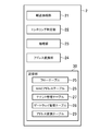
それぞれが、自身に設定されたフローエントリに基づいてパケットを処理する処理部を備える複数のスイッチと、
前記複数のスイッチのそれぞれにフローエントリを設定するコントローラとを備え、
前記複数のスイッチは、前記サーバ装置が接続された第1のスイッチと、前記テナント識別情報を認識できない機器が接続された第2のスイッチとを含み、
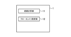
前記コントローラは、前記サーバ装置の前記VMから送信されるパケットを前記テナント識別情報を含む付加情報を付加してカプセル化する動作を規定したフローエントリを、前記第1のスイッチに設定し、前記カプセル化されたパケットから前記付加情報を除去する動作を規定したフローエントリを前記第2のスイッチに設定するフローエントリ設定部を備え、
前記第2のスイッチは、前記処理部により前記付加情報が除去されたパケットの送信元アドレスを、アドレス変換テーブルに基づいて前記第2のスイッチが管理するIPアドレスに変換するアドレス変換部と、前記送信元アドレスが変換された前記パケットを前記機器に送信する転送処理部と
を備えるマルチテナントシステム。 A server device on which a virtual machine (VM) to which tenant identification information is assigned operates;
A plurality of switches each including a processing unit for processing a packet based on a flow entry set in itself;
A controller for setting a flow entry in each of the plurality of switches,
The plurality of switches include a first switch to which the server device is connected, and a second switch to which a device that cannot recognize the tenant identification information is connected,
The controller sets, in the first switch, a flow entry that defines an operation for encapsulating a packet transmitted from the VM of the server device with additional information including the tenant identification information added thereto, A flow entry setting unit that sets, in the second switch, a flow entry that defines an operation for removing the additional information from the converted packet;
The second switch includes: an address conversion unit that converts a source address of the packet from which the additional information has been removed by the processing unit into an IP address managed by the second switch based on an address conversion table; A multi-tenant system comprising: a transfer processing unit that transmits the packet with the source address converted to the device. - 前記コントローラは、前記パケットと前記パケットのテナント識別情報を、パケットアウトメッセージに含めてパケットアウトし、
前記第1のスイッチの処理部は、前記パケットアウトメッセージに基づいて、前記パケットをカプセル化する
請求項1に記載のマルチテナントシステム。 The controller includes the packet and tenant identification information of the packet in a packet-out message to packet-out,
The multi-tenant system according to claim 1, wherein the processing unit of the first switch encapsulates the packet based on the packet-out message. - 前記第2のスイッチは、前記カプセル化パケットの受信時に、前記カプセル化パケットに含まれる前記第1のスイッチのIPアドレス、送信元VMのIPアドレス、及び前記テナント識別情報を、前記アドレス変換テーブルに記録し、
前記コントローラのフローエントリ設定部は、前記機器から送信されるパケットを、前記テナント識別情報を含む付加情報を付加してカプセル化する動作を規定するフローエントリを前記第2のスイッチに設定し、前記カプセル化されたパケットから前記付加情報を除去する動作を規定するフローエントリを前記第1のスイッチに設定し、
前記第2のスイッチの前記転送処理部は、前記機器から前記VMに送信されるリプライパケットを受信し、
前記第2のスイッチの前記アドレス変換部は、前記アドレス変換テーブルに基づいて、前記リプライパケットの送信先IPアドレスを、前記送信元VMのIPアドレスに変換し、
前記第2のスイッチの前記処理部は、送信元IPアドレスが変換された前記リプライパケットを、前記VMのテナント識別情報を含む付加情報が付加されたカプセル化リプライパケットにカプセル化し、前記付加情報内のL3ヘッダの送信先IPアドレスとして、前記アドレス変換テーブルの前記第1のスイッチのIPアドレスが設定され、
前記第1のスイッチの前記処理部は、前記カプセル化されたリプライパケットの前記付加情報を除去し、
前記第1のスイッチの前記転送処理部は、前記付加情報が除去されたリプライパケットを、前記VMに送信する
請求項1又は2のいずれか1項に記載のマルチテナントシステム。 When the second switch receives the encapsulated packet, the second switch includes the IP address of the first switch, the IP address of the transmission source VM, and the tenant identification information included in the encapsulated packet in the address conversion table. Record,
The flow entry setting unit of the controller sets, in the second switch, a flow entry that defines an operation of encapsulating a packet transmitted from the device with additional information including the tenant identification information added thereto, Setting a flow entry in the first switch that defines an operation for removing the additional information from the encapsulated packet;
The transfer processing unit of the second switch receives a reply packet transmitted from the device to the VM;
The address conversion unit of the second switch converts a transmission destination IP address of the reply packet to an IP address of the transmission source VM based on the address conversion table,
The processing unit of the second switch encapsulates the reply packet in which the source IP address is converted into an encapsulated reply packet to which additional information including tenant identification information of the VM is added. The IP address of the first switch of the address conversion table is set as the destination IP address of the L3 header of
The processing unit of the first switch removes the additional information of the encapsulated reply packet;
The multi-tenant system according to claim 1, wherein the transfer processing unit of the first switch transmits a reply packet from which the additional information is removed to the VM. - 前記第2のスイッチの前記アドレス変換部は、前記パケットの送信元ポート番号を、前記第2のスイッチが管理するポート番号に更に変換し、前記リプライパケットの送信先ポート番号を、前記変換前の元のポート番号に更に変換する
請求項1乃至3のいずれか1項に記載のマルチテナントシステム。 The address conversion unit of the second switch further converts the transmission source port number of the packet into a port number managed by the second switch, and converts the transmission destination port number of the reply packet before the conversion. The multi-tenant system according to any one of claims 1 to 3, wherein the multi-tenant system is further converted into an original port number. - 請求項1乃至4のいずれか1項に記載のマルチテナントシステムに使用されるコントローラ。 A controller used in the multi-tenant system according to any one of claims 1 to 4.
- 請求項1乃至4のいずれか1項に記載のマルチテナントシステムに使用されるスイッチ。 A switch used in the multi-tenant system according to any one of claims 1 to 4.
- マルチテナントシステムにおけるパケット転送方法であって、
VM(Virtual Machine)が、テナント識別情報を認識できない機器宛にパケットを送信するステップと、
第1のスイッチが、前記パケットを、コントローラにパケットインするステップと、
前記コントローラが、前記パケットの往路経路を計算するステップと、
前記コントローラが、前記パケットを転送するためのフローエントリを、前記往路経路上のスイッチに設定するステップと、
前記設定するステップでは、前記VMのテナント識別情報を含む付加情報を前記パケットに付加してカプセル化する動作を規定したフローエントリが、第1のスイッチに設定され、カプセル化されたパケットから付加情報を除去する動作を規定したフローエントリが第2のスイッチに設定され、
第1のスイッチが、自身に設定されたフローエントリに従い、前記パケットを、前記VMのテナント識別情報を含む付加情報を付加してカプセル化するステップと、
前記第2のスイッチが、前記カプセル化されたパケットを受信するステップと、
前記第2のスイッチが、自身に設定されたフローエントリに従い、前記カプセル化されたパケットから前記付加情報を除去するステップと、
前記第2のスイッチが、アドレス変換テーブルに基づいて、前記付加情報が除去されたパケットの送信元IPアドレスを、前記第2のスイッチが管理するIPアドレスに変換するステップと、
前記第2のスイッチが、前記送信元IPアドレスが、前記変換されたパケットを、前記機器に送信するステップと
を含むパケット転送方法。 A packet transfer method in a multi-tenant system,
A VM (Virtual Machine) transmits a packet to a device that cannot recognize tenant identification information;
A first switch packeting the packet into a controller;
The controller calculating a forward path of the packet;
The controller setting a flow entry for forwarding the packet to a switch on the forward path;
In the setting step, a flow entry defining an operation for adding and encapsulating additional information including tenant identification information of the VM to the packet is set in the first switch, and the additional information is set from the encapsulated packet. A flow entry that defines the action to remove is set in the second switch,
A first switch encapsulating the packet with additional information including tenant identification information of the VM according to a flow entry set in the first switch;
The second switch receiving the encapsulated packet;
The second switch removing the additional information from the encapsulated packet according to a flow entry set in the second switch;
The second switch translating a source IP address of the packet from which the additional information is removed into an IP address managed by the second switch based on an address translation table;
A packet transfer method comprising: a step in which the second switch transmits the packet whose source IP address is converted to the device. - 前記コントローラが、前記パケットと前記パケットのテナント識別情報を、パケットアウトメッセージに含めてパケットアウトするステップと
を更に含む
請求項7に記載のパケット転送方法。 The packet transfer method according to claim 7, further comprising: a step of packeting out the packet by including the packet and tenant identification information of the packet in a packet-out message. - 前記受信するステップにおいて、前記カプセル化されたパケットを受信した前記第2のスイッチが、前記カプセル化されたパケットに含まれる前記第1のスイッチのIPアドレス、送信元VMのIPアドレス、及び前記テナント識別情報を、前記アドレス変換テーブルに記録するステップと、
前記機器が、前記VMにリプライパケットを送信するステップと、
前記第2のスイッチが、アドレス変換テーブルに基づいて、送信先IPアドレスを、前記送信元VMのIPアドレスに変換するステップと、
前記第2のスイッチが、前記リプライパケットを、前記VMのテナント識別情報を含む付加情報が付加されたカプセル化リプライパケットにカプセル化するステップと、
前記記付加情報内のL3ヘッダの送信先IPアドレスとして、前記アドレス変換テーブルの前記第1のスイッチのIPアドレスが設定され、
前記第2のスイッチが、前記カプセル化リプライパケットを、コントローラにパケットインするステップと、
前記コントローラが、前記カプセル化リプライパケットの復路経路を計算するステップと、
前記コントローラが、前記カプセル化リプライパケットを転送するためのフローエントリを、前記復路経路上のスイッチに設定するステップと、前記設定するステップは、前記第1のスイッチには、前記付加情報を除去する設定を更に行い、
前記コントローラが、前記第2のスイッチに、前記カプセル化リプライパケットをパケットアウトするステップと、
前記第2のスイッチが、前記カプセル化リプライパケットを、前記第1のスイッチに送信するステップと、
前記第1のスイッチが、前記カプセル化リプライパケットを受信するステップと、
前記第1のスイッチが、前記フローエントリに基づいて、前記付加情報を除去するステップと、
前記第1のスイッチが、前記付加情報が除去された前記リプライパケットを、前記VMに送信するステップと
を更に含む請求項7又は8に記載のパケット転送方法。 In the receiving step, the second switch that has received the encapsulated packet receives the IP address of the first switch, the IP address of the transmission source VM, and the tenant included in the encapsulated packet. Recording identification information in the address translation table;
The device transmits a reply packet to the VM;
The second switch translating a destination IP address into an IP address of the source VM based on an address translation table;
The second switch encapsulates the reply packet into an encapsulated reply packet to which additional information including tenant identification information of the VM is added;
The IP address of the first switch of the address conversion table is set as the destination IP address of the L3 header in the additional information,
The second switch packetizing the encapsulated reply packet into a controller;
The controller calculating a return path of the encapsulated reply packet;
The controller sets a flow entry for transferring the encapsulated reply packet to the switch on the return path, and the setting step removes the additional information from the first switch. Make further settings,
The controller packeting out the encapsulated reply packet to the second switch;
The second switch sending the encapsulated reply packet to the first switch;
The first switch receiving the encapsulated reply packet;
The first switch removing the additional information based on the flow entry;
The packet transfer method according to claim 7 or 8, further comprising: the first switch transmitting the reply packet from which the additional information is removed to the VM. - 前記パケットをカプセル化するステップは、前記パケットの送信元ポート番号を、前記第2のスイッチが管理するポート番号に変換したパケットをカプセル化するステップを備え、
前記カプセル化リプライパケットにカプセル化するステップは、前記リプライパケットの送信先ポート番号を、前記変換前の元のポート番号に変換したリプライパケットをカプセル化するステップを備える
請求項7乃至9のいずれか1項に記載のパケット転送方法。 The step of encapsulating the packet comprises the step of encapsulating a packet obtained by converting a transmission source port number of the packet into a port number managed by the second switch;
The step of encapsulating in the encapsulated reply packet includes the step of encapsulating the reply packet obtained by converting the transmission destination port number of the reply packet into the original port number before the conversion. 2. The packet transfer method according to item 1.
Priority Applications (5)
| Application Number | Priority Date | Filing Date | Title |
|---|---|---|---|
| JP2014515659A JP5871063B2 (en) | 2012-05-15 | 2013-05-15 | Multi-tenant system, switch, controller, and packet transfer method |
| CN201380025327.8A CN104322022B (en) | 2012-05-15 | 2013-05-15 | Multi-tenant system, interchanger, controller and block transmission method |
| EP13791085.7A EP2852112A4 (en) | 2012-05-15 | 2013-05-15 | Multi-tenant system, switch, controller, and packet transfer method |
| US14/401,003 US9654394B2 (en) | 2012-05-15 | 2013-05-15 | Multi-tenant system, switch, controller and packet transferring method |
| IN9612DEN2014 IN2014DN09612A (en) | 2012-05-15 | 2014-11-14 |
Applications Claiming Priority (2)
| Application Number | Priority Date | Filing Date | Title |
|---|---|---|---|
| JP2012-111881 | 2012-05-15 | ||
| JP2012111881 | 2012-05-15 |
Publications (1)
| Publication Number | Publication Date |
|---|---|
| WO2013172391A1 true WO2013172391A1 (en) | 2013-11-21 |
Family
ID=49583795
Family Applications (1)
| Application Number | Title | Priority Date | Filing Date |
|---|---|---|---|
| PCT/JP2013/063603 WO2013172391A1 (en) | 2012-05-15 | 2013-05-15 | Multi-tenant system, switch, controller, and packet transfer method |
Country Status (6)
| Country | Link |
|---|---|
| US (1) | US9654394B2 (en) |
| EP (1) | EP2852112A4 (en) |
| JP (1) | JP5871063B2 (en) |
| CN (1) | CN104322022B (en) |
| IN (1) | IN2014DN09612A (en) |
| WO (1) | WO2013172391A1 (en) |
Cited By (4)
| Publication number | Priority date | Publication date | Assignee | Title |
|---|---|---|---|---|
| WO2017150621A1 (en) * | 2016-03-02 | 2017-09-08 | 日本電気株式会社 | Network system, terminal, sensor data collection method, and program |
| WO2017150642A1 (en) * | 2016-03-02 | 2017-09-08 | 日本電気株式会社 | Network system, control device, method and program for building virtual network function |
| WO2017150623A1 (en) * | 2016-03-02 | 2017-09-08 | 日本電気株式会社 | Network system, control device, method for building virtual network, and program |
| CN108712338A (en) * | 2013-12-11 | 2018-10-26 | 华为技术有限公司 | Message processing method and device |
Families Citing this family (7)
| Publication number | Priority date | Publication date | Assignee | Title |
|---|---|---|---|---|
| TW201613310A (en) * | 2014-09-30 | 2016-04-01 | Ibm | Method, appliance, and computer program product of translating network attributes of packets in a multi-tenant environment |
| CN106034052B (en) * | 2015-03-13 | 2019-05-17 | 北京网御星云信息技术有限公司 | The system and method that two laminar flow amounts are monitored a kind of between of virtual machine |
| US9729348B2 (en) * | 2015-06-04 | 2017-08-08 | Cisco Technology, Inc. | Tunnel-in-tunnel source address correction |
| US10728342B1 (en) * | 2016-06-30 | 2020-07-28 | EMP IP Holding Company LLC | Plug and play multi tenancy support for cloud applications |
| CN107733799B (en) | 2016-08-11 | 2021-09-21 | 新华三技术有限公司 | Message transmission method and device |
| US11405335B2 (en) * | 2017-01-13 | 2022-08-02 | Nicira, Inc. | Managing network traffic in virtual switches based on logical port identifiers |
| US11778038B2 (en) | 2021-12-14 | 2023-10-03 | Cisco Technology, Inc. | Systems and methods for sharing a control connection |
Citations (7)
| Publication number | Priority date | Publication date | Assignee | Title |
|---|---|---|---|---|
| JP2001136198A (en) * | 1999-11-04 | 2001-05-18 | Nippon Telegr & Teleph Corp <Ntt> | Inter-network communication method and server, and inter-network communication system |
| JP2006128803A (en) * | 2004-10-26 | 2006-05-18 | Japan Telecom Co Ltd | Memory relaying apparatus and network system |
| JP2009152953A (en) | 2007-12-21 | 2009-07-09 | Nec Corp | Gateway apparatus, packet forwarding method |
| WO2010115060A2 (en) * | 2009-04-01 | 2010-10-07 | Nicira Networks | Method and apparatus for implementing and managing virtual switches |
| WO2011142972A2 (en) * | 2010-05-14 | 2011-11-17 | Microsoft Corporation | Interconnecting members of a virtual network |
| JP2012111881A (en) | 2010-11-25 | 2012-06-14 | Fujifilm Corp | Light-diffusible resin composition and light-diffusing member |
| WO2013069133A1 (en) * | 2011-11-10 | 2013-05-16 | 株式会社日立製作所 | Frame relay apparatus, communication system, and data transfer method |
Family Cites Families (5)
| Publication number | Priority date | Publication date | Assignee | Title |
|---|---|---|---|---|
| CN101639770A (en) * | 2008-07-30 | 2010-02-03 | 国际商业机器公司 | System and method for supporting multi-tenant separation/multi-tenant customization in JVM |
| US8989187B2 (en) | 2010-06-04 | 2015-03-24 | Coraid, Inc. | Method and system of scaling a cloud computing network |
| CN103081418B (en) | 2010-09-09 | 2015-07-08 | 日本电气株式会社 | Computer system and communication method in computer system |
| JP5707239B2 (en) * | 2011-06-02 | 2015-04-22 | 株式会社日立製作所 | Multi-tenant information processing system, management server, and configuration management method |
| CN103563329B (en) * | 2011-06-07 | 2017-04-12 | 慧与发展有限责任合伙企业 | Scalable multi-tenant network architecture for virtualized datacenters |
-
2013
- 2013-05-15 JP JP2014515659A patent/JP5871063B2/en active Active
- 2013-05-15 WO PCT/JP2013/063603 patent/WO2013172391A1/en active Application Filing
- 2013-05-15 US US14/401,003 patent/US9654394B2/en active Active
- 2013-05-15 CN CN201380025327.8A patent/CN104322022B/en not_active Expired - Fee Related
- 2013-05-15 EP EP13791085.7A patent/EP2852112A4/en not_active Withdrawn
-
2014
- 2014-11-14 IN IN9612DEN2014 patent/IN2014DN09612A/en unknown
Patent Citations (7)
| Publication number | Priority date | Publication date | Assignee | Title |
|---|---|---|---|---|
| JP2001136198A (en) * | 1999-11-04 | 2001-05-18 | Nippon Telegr & Teleph Corp <Ntt> | Inter-network communication method and server, and inter-network communication system |
| JP2006128803A (en) * | 2004-10-26 | 2006-05-18 | Japan Telecom Co Ltd | Memory relaying apparatus and network system |
| JP2009152953A (en) | 2007-12-21 | 2009-07-09 | Nec Corp | Gateway apparatus, packet forwarding method |
| WO2010115060A2 (en) * | 2009-04-01 | 2010-10-07 | Nicira Networks | Method and apparatus for implementing and managing virtual switches |
| WO2011142972A2 (en) * | 2010-05-14 | 2011-11-17 | Microsoft Corporation | Interconnecting members of a virtual network |
| JP2012111881A (en) | 2010-11-25 | 2012-06-14 | Fujifilm Corp | Light-diffusible resin composition and light-diffusing member |
| WO2013069133A1 (en) * | 2011-11-10 | 2013-05-16 | 株式会社日立製作所 | Frame relay apparatus, communication system, and data transfer method |
Non-Patent Citations (1)
| Title |
|---|
| See also references of EP2852112A4 |
Cited By (11)
| Publication number | Priority date | Publication date | Assignee | Title |
|---|---|---|---|---|
| CN108712338A (en) * | 2013-12-11 | 2018-10-26 | 华为技术有限公司 | Message processing method and device |
| CN108712338B (en) * | 2013-12-11 | 2021-06-22 | 华为技术有限公司 | Message processing method and device |
| US11134009B2 (en) | 2013-12-11 | 2021-09-28 | Huawei Technologies Co., Ltd. | Packet processing method and apparatus |
| WO2017150621A1 (en) * | 2016-03-02 | 2017-09-08 | 日本電気株式会社 | Network system, terminal, sensor data collection method, and program |
| WO2017150642A1 (en) * | 2016-03-02 | 2017-09-08 | 日本電気株式会社 | Network system, control device, method and program for building virtual network function |
| WO2017150623A1 (en) * | 2016-03-02 | 2017-09-08 | 日本電気株式会社 | Network system, control device, method for building virtual network, and program |
| CN108702323A (en) * | 2016-03-02 | 2018-10-23 | 日本电气株式会社 | Network system, control device, the construction method of virtual network and program |
| JPWO2017150621A1 (en) * | 2016-03-02 | 2018-12-20 | 日本電気株式会社 | Network system, terminal, sensor data collection method and program |
| US10979394B2 (en) | 2016-03-02 | 2021-04-13 | Nec Corporation | Network system, control apparatus, method for constructing a virtual network, and program |
| CN108702323B (en) * | 2016-03-02 | 2021-06-01 | 日本电气株式会社 | Network system, control device, virtual network construction method, and computer-readable storage medium |
| US11438417B2 (en) | 2016-03-02 | 2022-09-06 | Nec Corporation | Network system, terminal, sensor data collection method, and program |
Also Published As
| Publication number | Publication date |
|---|---|
| IN2014DN09612A (en) | 2015-07-31 |
| CN104322022B (en) | 2017-10-24 |
| US9654394B2 (en) | 2017-05-16 |
| JPWO2013172391A1 (en) | 2016-01-12 |
| JP5871063B2 (en) | 2016-03-01 |
| US20150146736A1 (en) | 2015-05-28 |
| EP2852112A4 (en) | 2016-01-13 |
| EP2852112A1 (en) | 2015-03-25 |
| CN104322022A (en) | 2015-01-28 |
Similar Documents
| Publication | Publication Date | Title |
|---|---|---|
| JP5871063B2 (en) | Multi-tenant system, switch, controller, and packet transfer method | |
| US10862732B2 (en) | Enhanced network virtualization using metadata in encapsulation header | |
| US10237089B2 (en) | Packet tunneling method, switching device, and control device | |
| TWI744359B (en) | Method for data transmission and network equipment | |
| US11184842B2 (en) | Conveying non-access stratum messages over ethernet | |
| US8885649B2 (en) | Method, apparatus, and system for implementing private network traversal | |
| CN110999265B (en) | Managing network connectivity between cloud computing service endpoints and virtual machines | |
| US20150358232A1 (en) | Packet Forwarding Method and VXLAN Gateway | |
| JP7432095B2 (en) | How to forward packets in SRv6 service function chain, SFF, and SF devices | |
| CN104871495A (en) | Overlay virtual gateway for overlay networks | |
| CN107770026B (en) | Tenant network data transmission method, tenant network system and related equipment | |
| CN112671628B (en) | Business service providing method and system | |
| US8737396B2 (en) | Communication method and communication system | |
| KR20150076041A (en) | System for supporting multi-tenant based on private ip address in virtual private cloud networks and operating method thereof | |
| EP2548346B1 (en) | Packet node for applying service path routing at the mac layer | |
| WO2021073555A1 (en) | Service providing method and system, and remote acceleration gateway | |
| CN109246016B (en) | Cross-VXLAN message processing method and device | |
| US9847929B2 (en) | Cluster and forwarding method | |
| JP6718739B2 (en) | Communication device and communication method | |
| CN104363176A (en) | Message control method and equipment | |
| Lim et al. | Design and implementation of hardware accelerated VTEP in datacenter networks | |
| WO2016013118A1 (en) | Relay apparatus, network system, and network system control method | |
| Yang et al. | Openflow-based IPv6 rapid deployment mechanism | |
| JP2003244213A (en) | Packet communication method for adding tunnel path |
Legal Events
| Date | Code | Title | Description |
|---|---|---|---|
| 121 | Ep: the epo has been informed by wipo that ep was designated in this application |
Ref document number: 13791085 Country of ref document: EP Kind code of ref document: A1 |
|
| WWE | Wipo information: entry into national phase |
Ref document number: 14401003 Country of ref document: US Ref document number: 2013791085 Country of ref document: EP |
|
| ENP | Entry into the national phase |
Ref document number: 2014515659 Country of ref document: JP Kind code of ref document: A |
|
| NENP | Non-entry into the national phase |
Ref country code: DE |