WO2013172283A1 - Vehicle control device, and vehicle control method - Google Patents
Vehicle control device, and vehicle control method Download PDFInfo
- Publication number
- WO2013172283A1 WO2013172283A1 PCT/JP2013/063242 JP2013063242W WO2013172283A1 WO 2013172283 A1 WO2013172283 A1 WO 2013172283A1 JP 2013063242 W JP2013063242 W JP 2013063242W WO 2013172283 A1 WO2013172283 A1 WO 2013172283A1
- Authority
- WO
- WIPO (PCT)
- Prior art keywords
- control
- sprung
- wheel speed
- damping force
- estimated accuracy
- Prior art date
Links
Images


Classifications
-
- B—PERFORMING OPERATIONS; TRANSPORTING
- B60—VEHICLES IN GENERAL
- B60G—VEHICLE SUSPENSION ARRANGEMENTS
- B60G17/00—Resilient suspensions having means for adjusting the spring or vibration-damper characteristics, for regulating the distance between a supporting surface and a sprung part of vehicle or for locking suspension during use to meet varying vehicular or surface conditions, e.g. due to speed or load
- B60G17/015—Resilient suspensions having means for adjusting the spring or vibration-damper characteristics, for regulating the distance between a supporting surface and a sprung part of vehicle or for locking suspension during use to meet varying vehicular or surface conditions, e.g. due to speed or load the regulating means comprising electric or electronic elements
- B60G17/018—Resilient suspensions having means for adjusting the spring or vibration-damper characteristics, for regulating the distance between a supporting surface and a sprung part of vehicle or for locking suspension during use to meet varying vehicular or surface conditions, e.g. due to speed or load the regulating means comprising electric or electronic elements characterised by the use of a specific signal treatment or control method
- B60G17/0182—Resilient suspensions having means for adjusting the spring or vibration-damper characteristics, for regulating the distance between a supporting surface and a sprung part of vehicle or for locking suspension during use to meet varying vehicular or surface conditions, e.g. due to speed or load the regulating means comprising electric or electronic elements characterised by the use of a specific signal treatment or control method involving parameter estimation, e.g. observer, Kalman filter
-
- B—PERFORMING OPERATIONS; TRANSPORTING
- B60—VEHICLES IN GENERAL
- B60G—VEHICLE SUSPENSION ARRANGEMENTS
- B60G17/00—Resilient suspensions having means for adjusting the spring or vibration-damper characteristics, for regulating the distance between a supporting surface and a sprung part of vehicle or for locking suspension during use to meet varying vehicular or surface conditions, e.g. due to speed or load
- B60G17/015—Resilient suspensions having means for adjusting the spring or vibration-damper characteristics, for regulating the distance between a supporting surface and a sprung part of vehicle or for locking suspension during use to meet varying vehicular or surface conditions, e.g. due to speed or load the regulating means comprising electric or electronic elements
- B60G17/018—Resilient suspensions having means for adjusting the spring or vibration-damper characteristics, for regulating the distance between a supporting surface and a sprung part of vehicle or for locking suspension during use to meet varying vehicular or surface conditions, e.g. due to speed or load the regulating means comprising electric or electronic elements characterised by the use of a specific signal treatment or control method
-
- B—PERFORMING OPERATIONS; TRANSPORTING
- B60—VEHICLES IN GENERAL
- B60G—VEHICLE SUSPENSION ARRANGEMENTS
- B60G17/00—Resilient suspensions having means for adjusting the spring or vibration-damper characteristics, for regulating the distance between a supporting surface and a sprung part of vehicle or for locking suspension during use to meet varying vehicular or surface conditions, e.g. due to speed or load
- B60G17/015—Resilient suspensions having means for adjusting the spring or vibration-damper characteristics, for regulating the distance between a supporting surface and a sprung part of vehicle or for locking suspension during use to meet varying vehicular or surface conditions, e.g. due to speed or load the regulating means comprising electric or electronic elements
- B60G17/0195—Resilient suspensions having means for adjusting the spring or vibration-damper characteristics, for regulating the distance between a supporting surface and a sprung part of vehicle or for locking suspension during use to meet varying vehicular or surface conditions, e.g. due to speed or load the regulating means comprising electric or electronic elements characterised by the regulation being combined with other vehicle control systems
-
- B—PERFORMING OPERATIONS; TRANSPORTING
- B60—VEHICLES IN GENERAL
- B60G—VEHICLE SUSPENSION ARRANGEMENTS
- B60G17/00—Resilient suspensions having means for adjusting the spring or vibration-damper characteristics, for regulating the distance between a supporting surface and a sprung part of vehicle or for locking suspension during use to meet varying vehicular or surface conditions, e.g. due to speed or load
- B60G17/06—Characteristics of dampers, e.g. mechanical dampers
-
- B—PERFORMING OPERATIONS; TRANSPORTING
- B60—VEHICLES IN GENERAL
- B60G—VEHICLE SUSPENSION ARRANGEMENTS
- B60G2400/00—Indexing codes relating to detected, measured or calculated conditions or factors
- B60G2400/20—Speed
- B60G2400/204—Vehicle speed
-
- B—PERFORMING OPERATIONS; TRANSPORTING
- B60—VEHICLES IN GENERAL
- B60G—VEHICLE SUSPENSION ARRANGEMENTS
- B60G2400/00—Indexing codes relating to detected, measured or calculated conditions or factors
- B60G2400/40—Steering conditions
- B60G2400/41—Steering angle
Definitions
- the present invention relates to a control device and a control method for controlling the state of a vehicle.
- Patent Document 1 discloses a technique for estimating the stroke speed from the fluctuation of the wheel speed in a predetermined frequency region and changing the damping force of the damping force variable shock absorber according to the stroke speed to control the sprung behavior. .
- an object of the present invention is to provide a vehicle control device and a control method capable of detecting a decrease in the estimated accuracy of the sprung state.
- the sprung state is estimated based on information in the predetermined frequency region of the wheel speed detected by the wheel speed detecting means, and this sprung state is the target sprung state.
- this sprung state is the target sprung state.
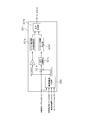
- FIG. 1 is a system schematic diagram illustrating a vehicle control apparatus according to a first embodiment.
- FIG. 2 is a control block diagram illustrating a control configuration of the vehicle control device according to the first embodiment.
- 1 is a conceptual diagram illustrating a configuration of a wheel speed feedback control system according to a first embodiment.
- FIG. 3 is a control block diagram illustrating a configuration of a traveling state estimation unit according to the first embodiment. It is a control block diagram showing the control content in the stroke speed calculating part of Example 1.
- FIG. 3 is a block diagram illustrating a configuration of a reference wheel speed calculation unit according to the first embodiment. It is the schematic showing a vehicle body vibration model. It is a control block diagram showing brake pitch control of Example 1.
- FIG. 3 is a control block diagram illustrating a configuration of roll rate suppression control according to the first embodiment. 3 is a time chart illustrating an envelope waveform forming process of roll rate suppression control according to the first embodiment.
- FIG. 3 is a block diagram illustrating a control configuration of unsprung vibration suppression control according to the first embodiment.
- FIG. 3 is a control block diagram illustrating a control configuration of a damping force control unit according to the first embodiment.
- 6 is a flowchart illustrating attenuation coefficient arbitration processing in a standard mode according to the first embodiment.
- 6 is a flowchart illustrating an attenuation coefficient arbitration process in the sport mode according to the first embodiment.
- 6 is a flowchart illustrating attenuation coefficient arbitration processing in the comfort mode according to the first embodiment.
- 6 is a flowchart illustrating attenuation coefficient arbitration processing in a highway mode according to the first exemplary embodiment.
- FIG. 6 is a flowchart illustrating a mode selection process based on a running state in an attenuation coefficient arbitration unit according to the first embodiment.
- FIG. 2 is a control block diagram illustrating a control configuration of the vehicle control device according to the first embodiment.
- FIG. 3 is a control block diagram illustrating a configuration of a control unit at the time of detection of a decrease in estimated accuracy according to the first embodiment. It is explanatory drawing showing the setting method of the attenuation coefficient at the time of the estimation accuracy fall in the attenuation coefficient setting part of Example 1.
- FIG. 1 is a system schematic diagram illustrating a vehicle control apparatus according to the first embodiment.
- the vehicle includes an engine 1 that is a power source and a brake 20 that generates braking torque due to friction force on each wheel (hereinafter, when displaying brakes corresponding to individual wheels, right front wheel brake: 20FR, left front wheel brake: 20FL).
- S / A shock absorber 3
- the engine 1 includes an engine controller (hereinafter also referred to as an engine control unit, which corresponds to power source control means) 1a that controls torque output from the engine 1, and the engine controller 1a is configured to By controlling the fuel injection amount, ignition timing, etc., the desired engine operating state (engine speed and engine output torque) is controlled. Further, the brake 20 generates a braking torque based on the hydraulic pressure supplied from the brake control unit 2 that can control the brake hydraulic pressure of each wheel according to the traveling state.
- the brake control unit 2 includes a brake controller (hereinafter also referred to as a brake control unit) 2a for controlling a braking torque generated by the brake 20, and a master cylinder pressure generated by a driver's brake pedal operation or a built-in motor.
- a pump pressure generated by the drive pump is used as a hydraulic pressure source, and a desired hydraulic pressure is generated in the brake 20 of each wheel by opening and closing operations of a plurality of solenoid valves.
- the S / A3 is a damping force generator that attenuates the elastic motion of a coil spring provided between a vehicle unsprung (axle, wheel, etc.) and a sprung (vehicle body, etc.). It is configured to be variable.
- the S / A 3 includes a cylinder in which fluid is sealed, a piston that strokes in the cylinder, and an orifice that controls fluid movement between fluid chambers formed above and below the piston. Furthermore, orifices having a plurality of types of orifice diameters are formed in the piston, and an orifice corresponding to a control command is selected from the plurality of types of orifices when the S / A actuator is operated. Thereby, the damping force according to the orifice diameter can be generated. For example, if the orifice diameter is small, the movement of the piston is easily restricted, so that the damping force is high. If the orifice diameter is large, the movement of the piston is difficult to be restricted, and thus the damping force is small.
- an electromagnetic control valve is arranged on the communication path connecting fluids formed above and below the piston, and the damping force is set by controlling the opening / closing amount of the electromagnetic control valve.
- the S / A 3 has an S / A controller 3a (corresponding to damping force control means) that controls the damping force of the S / A 3, and controls the damping force by operating the orifice diameter by the S / A actuator.
- a wheel speed sensor 5 for detecting the wheel speed of each wheel (hereinafter, when displaying the wheel speed corresponding to each wheel, right front wheel speed: 5FR, left front wheel speed: 5FL, right rear wheel speed: 5RR. , Left rear wheel speed: 5RL)), an integrated sensor 6 for detecting longitudinal acceleration, yaw rate and lateral acceleration acting on the center of gravity of the vehicle, and a steering angle which is a steering operation amount of the driver is detected.
- Steering angle sensor 7 vehicle speed sensor 8 for detecting vehicle speed
- engine torque sensor 9 for detecting engine torque
- engine speed sensor 10 for detecting engine speed
- master pressure sensor 11 for detecting master cylinder pressure.
- a brake switch 12 that outputs an on-state signal when the brake pedal is operated, an accelerator opening sensor 13 that detects an accelerator pedal opening, and an outside air temperature A temperature sensor 14 for detecting a.
- the signals from these various sensors are input to the engine controller 1a, the brake controller 2a, and the S / A controller 3a as necessary.
- the arrangement of the integrated sensor 6 may be at the center of gravity of the vehicle, or may be any place other than that as long as various values at the center of gravity can be estimated. Moreover, it is not necessary to be an integral type, and a configuration in which yaw rate, longitudinal acceleration, and lateral acceleration are individually detected may be employed.
- the control amount by the engine 1 and the brake 20 is limited and output from the control amount that can be actually output, thereby reducing the burden on the S / A 3 and accompanying the control of the engine 1 and the brake 20. Suppresses discomfort that occurs.
- Skyhook control is performed by all actuators. At this time, without using a stroke sensor or a sprung vertical acceleration sensor generally required for skyhook control, the skyhook control can be performed with an inexpensive configuration using wheel speed sensors mounted on all vehicles. Realize.
- scalar control frequency sensitive control
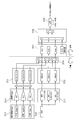
- FIG. 2 is a control block diagram illustrating a control configuration of the vehicle control apparatus according to the first embodiment.
- the controller includes an engine controller 1a, a brake controller 2a, and an S / A controller 3a, and each controller constitutes a wheel speed feedback control system.
- estimation that is the probability of state estimation of each of the traveling state estimation units (first traveling state estimation unit 100, second traveling state estimation unit 200, and third traveling state estimation unit 32) described later.
- An estimated accuracy decrease detection unit 4a that detects a decrease in accuracy
- an estimated accuracy decrease detection time control unit 5a that transitions to an appropriate control state when a decrease in estimated accuracy is detected.
- the configuration including three controllers as the controller is shown, but each controller may be configured from one integrated controller without any particular limitation.
- the configuration including the three controllers in the first embodiment is that the engine controller and the brake controller in the existing vehicle are used as they are to form the engine control unit 1a and the brake control unit 2a, and the S / A controller 3a is separately mounted.
- the vehicle control apparatus of the first embodiment is realized.
- the engine controller 1a mainly uses the wheel speed detected by the wheel speed sensor 5 to determine the stroke speed, bounce rate, roll rate and pitch of each wheel used for the skyhook control of the sprung mass damping control unit 101a described later.
- a first running state estimation unit 100 that estimates the rate, an engine posture control unit 101 that calculates an engine posture control amount that is an engine torque command, and controls the operating state of the engine 1 based on the calculated engine posture control amount.
- An engine control unit 102 The details of the estimation process of the first traveling state estimation unit 100 will be described later.
- the engine attitude control unit 101 includes a sprung mass damping control unit 101a that calculates a sprung control amount that suppresses bounce motion and pitch motion by skyhook control, and ground load variation suppression that suppresses ground load variation of front and rear wheels.
- a ground load control unit 101b that calculates a control amount
- an engine-side driver input control unit 101c that calculates a yaw response control amount corresponding to a vehicle behavior that the driver wants to achieve based on signals from the steering angle sensor 7 and the vehicle speed sensor 8 And have.
- the engine attitude control unit 101 calculates an engine attitude control amount that minimizes the control amount calculated by each of these control units by optimal control (LQR), and determines the final engine attitude control amount for the engine control unit 102. Output.
- LQR optimal control
- the S / A 3 can reduce the damping force control amount, and therefore, deterioration of the high frequency vibration can be avoided. Moreover, since S / A3 can concentrate on suppression of roll motion, it can suppress roll motion effectively.
- the brake controller 2a Based on the wheel speed detected by the wheel speed sensor 5, the brake controller 2a estimates the stroke speed and pitch rate of each wheel, and the like based on the estimated stroke speed and pitch rate.
- Skyhook control unit 201 (details will be described later) that calculates a brake attitude control amount based on skyhook control, and brake control unit 202 that controls the braking torque of brake 20 based on the calculated brake attitude control amount And have.
- the same estimation process is adopted as the estimation process in the first traveling state estimation unit 100 and the second traveling state estimation unit 200, but other estimation processes are performed as long as the process is estimated from the wheel speed. It may be used.
- the S / A controller 3a includes a driver input control unit 31 that performs driver input control for achieving a desired vehicle posture based on a driver's operation (steering operation, accelerator operation, brake pedal operation, etc.), and detection values of various sensors.
- a third traveling state estimation unit 32 that estimates the traveling state based on (mainly the wheel speed sensor value of the wheel speed sensor 5), and a sprung mass damping that controls the vibration state on the spring based on the estimated traveling state
- a control unit 33 an unsprung vibration suppression control unit 34 that controls the unsprung vibration state based on the estimated traveling state, a shock absorber attitude control amount output from the driver input control unit 31, and a sprung mass damping
- a damping force to be set in the S / A 3 is determined.
- a damping force control unit 35 for performing the damping force control of the A.
- the same estimation process is adopted as the estimation process in the first traveling state estimation unit 100, the second traveling state estimation unit 200, and the third traveling state estimation unit 32, but the process is estimated from the wheel speed. If so, other estimation processes may be used and there is no particular limitation.
- FIG. 3 is a conceptual diagram showing the configuration of the wheel speed feedback control system of the first embodiment.
- the engine 1, the brake 20 and the S / A 3 individually constitute an engine feedback control system, a brake feedback control system, and an S / A feedback control system.
- control interference becomes a problem.
- the effects of the control of each actuator appear as wheel speed fluctuations, by configuring the wheel speed feedback control system, the effect of each actuator is monitored as a result, and control interference is avoided. It is. For example, if a certain sprung vibration is suppressed by the engine 1, the wheel speed fluctuation
- the brake 20 and the S / A 3 perform control based on the wheel speed in which the influence is reflected.
- the feedback control system is configured using a common value of wheel speed, even if individual control is performed without controllable mutual monitoring, as a result, control based on mutual monitoring (below)
- This control is described as cooperative control), and the vehicle posture can be converged in the stabilization direction.
- each feedback control system will be described sequentially.
- the 1st, 2nd, 3rd driving state estimation part which is a common structure provided in each feedback control system is demonstrated.
- the same estimation process is adopted as the estimation process in the first traveling state estimation unit 100, the second traveling state estimation unit 200, and the third traveling state estimation unit 32. Therefore, since the process in each estimation part is common, the estimation process in the 3rd driving state estimation part 32 is demonstrated as a representative.
- Each of the running state estimation units may be provided with a separate estimation model as long as it is a state estimation using the wheel speed, and is not particularly limited.
- FIG. 4 is a control block diagram showing the configuration of the third traveling state estimation unit of the first embodiment.
- the stroke of each wheel used for the skyhook control of the sprung mass damping control unit 33 to be described later is basically based on the wheel speed detected by the wheel speed sensor 5. Calculate speed, bounce rate, roll rate and pitch rate. First, the value of the wheel speed sensor 5 of each wheel is input to the stroke speed calculation unit 321, and the sprung speed is calculated from the stroke speed of each wheel calculated by the stroke speed calculation unit 321.
- FIG. 5 is a control block diagram showing the control contents in the stroke speed calculation unit of the first embodiment.
- the stroke speed calculation unit 321 is individually provided for each wheel, and the control block diagram shown in FIG. 5 is a control block diagram focusing on a certain wheel.
- the value of the wheel speed sensor 5, the front wheel steering angle ⁇ f detected by the steering angle sensor 7, and the rear wheel steering angle ⁇ r (actual rear wheel steering if a rear wheel steering device is provided).
- the reference wheel speed calculation unit 300 that calculates a reference wheel speed based on the vehicle body lateral speed and the actual yaw rate detected by the integrated sensor 6, and the angle may be appropriately set to 0 in other cases.
- a tire rotation vibration frequency calculation unit 321a that calculates the tire rotation vibration frequency based on the calculated reference wheel speed, and a deviation calculation unit 321b that calculates a deviation (wheel speed fluctuation) between the reference wheel speed and the wheel speed sensor value.
- a GEO conversion unit 321c that converts the deviation calculated by the deviation calculation unit 321b into a suspension stroke amount, a stroke speed calibration unit 321d that calibrates the converted stroke amount to a stroke speed,
- a band elimination filter corresponding to the frequency calculated by the tire rotation vibration frequency calculation unit 321a is applied to the value calibrated by the roke speed calibration unit 321d to remove the tire rotation primary vibration component and calculate the final stroke speed.
- a signal processing unit 321e that calculates the tire rotation vibration frequency based on the calculated reference wheel speed
- a deviation calculation unit 321b that calculates a deviation (wheel speed fluctuation) between the reference wheel speed and the wheel speed sensor value.
- a GEO conversion unit 321c that converts the deviation calculated by the deviation calculation unit 321b into
- FIG. 6 is a block diagram illustrating a configuration of a reference wheel speed calculation unit according to the first embodiment.
- the reference wheel speed refers to a value obtained by removing various disturbances from each wheel speed.
- the difference between the wheel speed sensor value and the reference wheel speed is a value related to a component that fluctuates according to the stroke generated by the bounce behavior, roll behavior, pitch behavior, or unsprung vertical vibration of the vehicle body.
- the stroke speed is estimated based on this difference.
- the plane motion component extraction unit 301 calculates the first wheel speed V0 that is the reference wheel speed of each wheel based on the vehicle body plan view model with the wheel speed sensor value as an input.
- the wheel speed sensor value detected by the wheel speed sensor 5 is ⁇ (rad / s)
- the front wheel actual steering angle detected by the steering angle sensor 7 is ⁇ f (rad)
- the rear wheel actual steering angle is ⁇ r (rad )
- the vehicle body lateral speed is Vx
- the yaw rate detected by the integrated sensor 6 is ⁇ (rad / s)
- the vehicle speed estimated from the calculated reference wheel speed ⁇ 0 is V (m / s)
- the reference to be calculated Wheel speed is VFL, VFR, VRL, VRR
- front wheel tread is Tf
- rear wheel tread is Tr
- distance from vehicle center of gravity to front wheel is Lf
- distance from vehicle center of gravity to rear wheel is Lr.
- VFL (V-Tf / 2 ⁇ ⁇ ) cos ⁇ f + (Vx + Lf ⁇ ⁇ ) sin ⁇ f
- VFR (V + Tf / 2 ⁇ ⁇ ) cos ⁇ f + (Vx + Lf ⁇ ⁇ ) sin ⁇ f
- VRL (V ⁇ Tr / 2 ⁇ ⁇ ) cos ⁇ r + (Vx ⁇ Lr ⁇ ⁇ ) sin ⁇ r
- VRR (V + Tr / 2 ⁇ ⁇ ) cos ⁇ r + (Vx-Lr ⁇ ⁇ ) sin ⁇ r
- V is described as V0FL, V0FR, V0RL, V0RR (corresponding to the first wheel speed) as a value corresponding to each wheel.
- V0FL ⁇ VFL-Lf ⁇ ⁇ sin ⁇ f ⁇ / cos ⁇ f + Tf / 2 ⁇ ⁇
- V0FR ⁇ VFR-Lf ⁇ ⁇ sin ⁇ f ⁇ / cos ⁇ f-Tf / 2 ⁇ ⁇
- V0RL ⁇ VRL + Lr ⁇ ⁇ sin ⁇ r ⁇ / cos ⁇ r + Tr / 2 ⁇ ⁇
- V0RR ⁇ VRR + Lf ⁇ ⁇ sin ⁇ f ⁇ / cos ⁇ r-Tr / 2 ⁇ ⁇
- the roll disturbance removing unit 302 calculates the second wheel speeds V0F and V0R as the reference wheel speeds for the front and rear wheels based on the vehicle body front view model with the first wheel speed V0 as an input.
- the vehicle body front view model removes the wheel speed difference caused by the roll motion that occurs around the roll rotation center on the vertical line passing through the center of gravity of the vehicle when the vehicle is viewed from the front. Is done.
- V0F (V0FL + V0FR) / 2
- V0R (V0RL + V0RR) / 2
- the second wheel speeds V0F and V0R from which disturbance based on the roll is removed are obtained.
- the pitch disturbance removal unit 303 calculates the third wheel speeds VbFL, VbFR, VbRL, and VbRR, which are the reference wheel speeds for all the wheels, based on the vehicle side view model, with the second wheel speeds V0F and V0R as inputs.
- the vehicle body side view model is to remove the wheel speed difference caused by the pitch motion generated around the pitch rotation center on the vertical line passing through the center of gravity of the vehicle when the vehicle is viewed from the lateral direction. It is expressed by the following formula.
- the sprung speed calculation unit 322 calculates the bounce rate, roll rate, and pitch rate for skyhook control. Calculated.
- Skyhook control is to achieve a flat running state by setting a damping force based on the relationship between the S / A3 stroke speed and the sprung speed, and controlling the posture on the sprung.
- the value that can be detected from the wheel speed sensor 5 is the stroke speed, and since the vertical acceleration sensor or the like is not provided on the spring, the sprung speed needs to be estimated using an estimation model.
- the problem of the estimation model and the model configuration to be adopted will be described.
- FIG. 7 is a schematic diagram showing a vehicle body vibration model.
- FIG. 7A is a model of a vehicle (hereinafter referred to as a conveyor vehicle) having an S / A with a constant damping force
- FIG. 7B has an S / A having a variable damping force.
- Ms represents the mass on the spring
- Mu represents the mass below the spring
- Ks represents the elastic coefficient of the coil spring
- Cs represents the damping coefficient of S / A
- Ku represents the unsprung (tire).
- Cu represents an unsprung (tire) damping coefficient
- Cv represents a variable damping coefficient
- Z2 represents a position on the spring
- z1 represents a position under the spring
- z0 represents a road surface position.
- Changing the damping force basically means changing the force that limits the piston moving speed of S / A 3 in accordance with the suspension stroke. Since the semi-active S / A3 that cannot positively move the piston in the desired direction is used, when the semi-active skyhook model is employed and the sprung speed is obtained, it is expressed as follows.
- the magnitude of the estimated sprung speed is smaller than the actual value in the frequency band below the sprung resonance, but the most important in skyhook control is the phase. If the correspondence between the phase and the sign can be maintained, the skyhook can be maintained. Since control is achieved and the magnitude of the sprung speed can be adjusted by other factors, there is no problem.
- the sprung speed can be estimated if the stroke speed of each wheel is known.
- the actual vehicle is four wheels instead of one wheel, it is considered to estimate the state of the spring by mode decomposition into roll rate, pitch rate and bounce rate using the stroke speed of each wheel. To do.
- the above three components are calculated from the stroke speed of the four wheels, one corresponding component is insufficient, and the solution becomes indefinite. Therefore, a war plate representing the movement of the diagonal wheels is introduced.
- the stroke amount bounce term is xsB
- the roll term is xsR
- the pitch term is xsP
- the warp term is xsW
- the stroke amount corresponding to Vz_sFL, Vz_sFR, Vz_sRL, Vz_sRR is z_sFL, z_sFR, z_sRL, z_sRR, Holds.
- dxsB 1/4 (Vz_sFL + Vz_sFR + Vz_sRL + Vz_sRR)
- dxsR 1/4 (Vz_sFL-Vz_sFR + Vz_sRL-Vz_sRR)
- dxsP 1/4 (-Vz_sFL-Vz_sFR + Vz_sRL + Vz_sRR)
- dxsW 1/4 (-Vz_sFL + Vz_sFR + Vz_sRL-Vz_sRR)
- the vehicle control apparatus includes the engine 1, the brake 20, and the S / A 3 as actuators for achieving sprung posture control.
- the sprung mass damping control unit 101a in the engine controller 1a has two bounce rate and pitch rate as control targets
- the skyhook control unit 201 in the brake controller 2a has pitch rate as control targets.
- the skyhook control unit 33a in the controller 3a three of bounce rate, roll rate, and pitch rate are controlled.
- the bounce direction skyhook control amount FB is calculated as a part of the engine attitude control amount in the sprung mass damping control unit 101a.
- the skyhook control unit 33a calculates as a part of the S / A attitude control amount.
- the skyhook control amount FR in roll direction is calculated as part of the S / A attitude control amount in the sky hook control unit 33a.
- the sky hook control amount FP in the pitch direction is calculated as a part of the engine attitude control amount in the sprung mass damping control unit 101a.
- the skyhook control unit 201 calculates the brake posture control amount.
- the skyhook control unit 33a calculates as a part of the S / A attitude control amount.
- the engine attitude control unit 101 is set with a limit value for limiting the engine torque control amount according to the engine attitude control amount so as not to give the driver a sense of incongruity.
- the engine torque control amount is limited to be within a predetermined longitudinal acceleration range when converted to longitudinal acceleration. Therefore, when the engine attitude control amount (engine torque control amount) is calculated based on FB or FP and a value equal to or greater than the limit value is calculated, bounce rate or pitch rate skyhook control that can be achieved by the limit value
- the engine attitude control amount is output as a quantity.
- the engine control unit 102 calculates an engine torque control amount based on the engine attitude control amount corresponding to the limit value, and outputs the engine torque control amount to the engine 1.
- a limit value for limiting the braking torque control amount is set in order to prevent the driver from feeling uncomfortable as in the case of the engine 1 (details of the limit value will be described later).
- the braking torque control amount is converted into the longitudinal acceleration, the braking torque control amount is limited to be within a predetermined longitudinal acceleration range (a limit value obtained from the occupant's uncomfortable feeling, the life of the actuator, etc.). Therefore, when the brake attitude control amount is calculated based on the FP and a value equal to or greater than the limit value is calculated, a pitch rate suppression amount (hereinafter referred to as a brake attitude control amount) that can be achieved by the limit value.
- a pitch rate suppression amount hereinafter referred to as a brake attitude control amount
- the brake control unit 202 calculates a braking torque control amount (or deceleration) based on the brake attitude control amount corresponding to the limit value, and outputs it to the brake 20.
- FIG. 8 is a control block diagram showing the brake pitch control of the first embodiment.
- the vehicle body mass is m
- the front wheel braking force is BFf
- the rear wheel braking force is BFr
- the height between the vehicle center of gravity and the road surface is Hcg
- the vehicle acceleration is a
- the pitch moment is Mp
- the pitch rate is Vp.
- the brake attitude control amount calculation unit 334 is composed of the following control blocks.
- the dead zone processing code determination unit 3341 determines the sign of the input pitch rate Vp, and when it is positive, it outputs 0 to the deceleration reduction processing unit 3342 because control is unnecessary, and when it is negative, it determines that control is possible.
- the pitch rate signal is output to the deceleration reduction processing unit 3342.
- the deceleration feeling reduction process is a process corresponding to the limit by the limit value performed in the brake attitude control amount calculation unit 334.
- the square processor 3342a squares the pitch rate signal. This inverts the sign and smoothes the rise of the control force.
- the pitch rate square decay moment calculation unit 3342b calculates the pitch moment Mp by multiplying the squared pitch rate by the skyhook gain CskyP of the pitch term considering the square process.
- the target deceleration calculating unit 3342c calculates the target deceleration by dividing the pitch moment Mp by the mass m and the height Hcg between the vehicle center of gravity and the road surface.
- the calculated rate of change of the target deceleration that is, whether the jerk is within a preset range of the deceleration jerk threshold and the extraction jerk threshold, and the target deceleration is the longitudinal acceleration limit value. Judgment is made whether or not it is within the range. If any threshold is exceeded, the target deceleration is corrected to a value within the jerk threshold range, and if the target deceleration exceeds the limit value, the limit is set. Set within the value. Thereby, the deceleration can be generated so as not to give the driver a sense of incongruity.
- the target pitch moment conversion unit 3343 calculates the target pitch moment by multiplying the target deceleration limited by the jerk threshold limiting unit 3342d by the mass m and the height Hcg, and outputs the target pitch moment to the brake control unit 2a.
- the sprung speed is estimated based on the detection value of the wheel speed sensor 5 and the skyhook control is performed based on the estimated sprung speed control.
- a comfortable driving state (a comfortable ride feeling softer than the vehicle body flatness) is guaranteed.
- vector control where the relationship (phase, etc.) of the sign of stroke speed and sprung speed is important, such as skyhook control, may make it difficult to achieve proper control due to a slight phase shift. Therefore, we decided to introduce frequency-sensitive control, which is sprung mass damping control according to the scalar quantity of vibration characteristics.
- FIG. 9 is a diagram in which the wheel speed frequency characteristic detected by the wheel speed sensor and the stroke frequency characteristic of a stroke sensor not mounted in the embodiment are simultaneously written.
- the frequency characteristic is a characteristic in which the vertical axis represents the magnitude of the amplitude with respect to the frequency as a scalar quantity. Comparing the frequency component of the wheel speed sensor 5 with the frequency component of the stroke sensor, it can be understood that substantially the same scalar amount is taken from the sprung resonance frequency component to the unsprung resonance frequency component. Therefore, the damping force is set based on this frequency characteristic among the detection values of the wheel speed sensor 5.
- the area where the sprung resonance frequency component exists is felt as if the occupant was thrown into the air by swinging the entire body of the occupant, in other words, the feeling that the gravitational acceleration acting on the occupant was reduced.
- the frequency region that brings about the waving region (0.5 to 3 Hz), and the region between the sprung resonance frequency component and the unsprung resonance frequency component is not a feeling that gravitational acceleration decreases.
- the feeling that the human body jumps in small increments when performing (trot), in other words, the frequency range that brings up and down movement that the whole body can follow is the leopard region (3 to 6 Hz), and the region where the unsprung resonance frequency component exists Is not a vertical movement until the mass of the human body follows, but a bull region (6 to 6) is used as a frequency region where vibration is transmitted to a part of the body such as the occupant's thigh. 23 Hz).
- FIG. 10 is a control block diagram illustrating frequency sensitive control in the sprung mass damping control of the first embodiment.
- the band elimination filter 350 cuts noise other than the vibration component used for the main control from the wheel speed sensor value.
- the predetermined frequency domain dividing unit 351 divides the frequency band into a wide area, a horizontal area, and a bull area.
- the Hilbert transform processing unit 352 performs Hilbert transform on each divided frequency band, and converts it into a scalar quantity based on the amplitude of the frequency (specifically, an area calculated from the amplitude and the frequency band).
- the vehicle vibration system weight setting unit 353 sets weights at which vibrations in the frequency bands of the fur region, the leopard region, and the bull region are actually propagated to the vehicle.
- the human sense weight setting unit 354 sets weights at which vibrations in the frequency bands of the fur region, the leopard region, and the bull region are propagated to the occupant.
- FIG. 11 is a correlation diagram showing human sensory characteristics with respect to frequency.
- the occupant's sensitivity is relatively low with respect to the frequency, and the sensitivity gradually increases as the frequency shifts to the high frequency region.
- the high frequency region above the bull region becomes difficult to be transmitted to the occupant.
- the human sense weight Wf of the wafe area is set to 0.17
- the human sense weight Wh of the leopard area is set to 0.34 which is larger than Wf
- the human sense weight Wb of the bull area is larger than Wf and Wh. Set to 0.38.
- the weight determining unit 355 calculates the ratio of the weight of each frequency band to the weight of each frequency band. If the weight of the wing area is a, the weight of the leopard area is b, and the weight of the bull area is c, the weight coefficient of the wing area is (a / (a + b + c)), and the weight coefficient of the leap area is (b / (a + b + c). )), And the weighting factor of the bull area is (c / (a + b + c)).
- the scalar amount calculation unit 356 multiplies the scalar amount of each frequency band calculated by the Hilbert transform processing unit 352 by the weight calculated by the weight determination unit 355, and outputs a final scalar amount. The processing so far is performed on the wheel speed sensor value of each wheel.
- the maximum value selection unit 357 selects the maximum value from the final scalar amounts calculated for each of the four wheels. Note that 0.01 in the lower part is set to avoid the denominator becoming 0 because the sum of the maximum values is used as the denominator in the subsequent processing.
- the ratio calculation unit 358 calculates the ratio using the sum of the scalar value maximum values in each frequency band as the denominator and the scalar value maximum value in the frequency band corresponding to the waving region as the numerator. In other words, the mixing ratio (hereinafter simply referred to as the ratio) of the wafer region included in all vibration components is calculated.
- the sprung resonance filter 359 performs filter processing of about 1.2 Hz of the sprung resonance frequency with respect to the calculated ratio, and extracts a sprung resonance frequency band component representing a waft region from the calculated ratio. In other words, since the wing area exists at about 1.2 Hz, the ratio of this area is considered to change at about 1.2 Hz. Then, the finally extracted ratio is output to the damping force control unit 35, and a frequency sensitive damping force control amount corresponding to the ratio is output.
- FIG. 12 is a characteristic diagram showing the relationship between the vibration mixing ratio in the waft region and the damping force by the frequency sensitive control of the first embodiment.
- the vibration level of sprung resonance is reduced by setting the damping force high when the ratio of the wing area is large.
- the damping force is set high, the ratio of the leopard area and the bull area is small, so that high frequency vibration or vibration that moves with the leopard is not transmitted to the occupant.
- the damping force is set low, so that the vibration transmission characteristic more than the sprung resonance is reduced, the high frequency vibration is suppressed, and a smooth riding comfort is obtained.
- FIG. 13 is a diagram showing the wheel speed frequency characteristics detected by the wheel speed sensor 5 under a certain traveling condition. This is a characteristic that appears particularly when traveling on a road surface in which small unevenness such as a stone pavement continues.
- the damping force is determined by the value of the amplitude peak in Skyhook control. There is a problem that a very high damping force is set at an incorrect timing and high-frequency vibration is deteriorated.
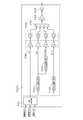
- FIG. 14 is a control block diagram illustrating the configuration of roll rate suppression control according to the first embodiment.
- the lateral acceleration estimation unit 31b1 the front wheel rudder angle ⁇ f detected by the rudder angle sensor 7 and the rear wheel rudder angle ⁇ r (the actual rear wheel rudder angle if a rear wheel steering device is provided, and 0 in other cases as appropriate)
- the lateral acceleration Yg is estimated based on the vehicle speed VSP detected by the vehicle speed sensor 8. This lateral acceleration Yg is calculated by the following equation using the yaw rate estimated value ⁇ .
- Yg VSP ⁇ ⁇
- the yaw rate estimated value ⁇ is calculated by the following equation.
- the 90 ° phase advance component creation unit 31b2 differentiates the estimated lateral acceleration Yg and outputs a lateral acceleration differential value dYg.
- the 90 ° phase delay component creation unit 31b3 outputs a component F (dYg) obtained by delaying the phase of the lateral acceleration differential value dYg by 90 °.
- the component F (dYg) is obtained by returning the phase of the component from which the low-frequency region has been removed by the 90 ° phase advance component creation unit 31b2 to the phase of the lateral acceleration Yg. It is a transient component of acceleration Yg.
- the 90 ° phase delay component creation unit 31b4 outputs a component F (Yg) obtained by delaying the phase of the estimated lateral acceleration Yg by 90 °.
- the gain multiplication unit 31b5 multiplies the lateral acceleration Yg, the lateral acceleration differential value dYg, the lateral acceleration DC cut component F (dYg), and the 90 ° phase delay component F (Yg) by a gain. Each gain is set based on a roll rate transfer function with respect to the steering angle. Each gain may be adjusted according to four control modes described later.
- the square calculator 31b6 squares and outputs each component multiplied by the gain.
- the combining unit 31b7 adds the values output from the square calculation unit 31b6.
- the gain multiplication unit 31b8 multiplies the square value of each added component by the gain and outputs the result.
- the square root calculation unit 31b9 calculates a driver input attitude control amount for roll rate suppression control by calculating the square root of the value output from the gain multiplication unit 31b7, and outputs the calculated value to the damping force control unit 35.
- 90 ° phase advance component creation unit 31b2, 90 ° phase lag component creation unit 31b3, 90 ° phase lag component creation unit 31b4, gain multiplication unit 31b5, square operation unit 31b6, synthesis unit 31b7, gain multiplication unit 31b8, square root operation unit 31b9 Corresponds to the Hilbert transform unit 31b10 that generates an envelope waveform using the Hilbert transform.
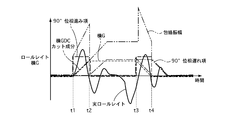
- FIG. 15 is a time chart showing an envelope waveform forming process of the roll rate suppressing control according to the first embodiment.
- the driver starts steering at time t1
- roll rate begins to gradually occur.
- the 90 ° phase advance component dYg is added to form an envelope waveform
- the driver input attitude control amount is calculated based on the scalar amount based on the envelope waveform, thereby suppressing the occurrence of roll rate in the initial stage of steering.
- Can do Furthermore, by adding the lateral acceleration DC cut component F (dYg) to form an envelope waveform, it effectively suppresses the roll rate that occurs in a transitional state when the driver starts or ends steering. Can do. In other words, in a steady turning state in which the generation of rolls is stable, the damping force is not excessively increased, and deterioration in riding comfort can be avoided.
- the 90 ° phase advance component dYg and the lateral acceleration DC cut component F (dYg) disappear, and this time, the 90 ° phase delay component F (Yg) is added.
- the phase delay component F (Yg) is not added, the damping force from the time t2 to the time t3 is set to a small value, which may cause the vehicle behavior to become unstable due to the roll rate resonance component.
- a 90 ° phase delay component F (Yg) is added.
- FIG. 16 is a block diagram illustrating a control configuration of unsprung vibration suppression control according to the first embodiment.
- the unsprung resonance component extraction unit 341 extracts a unsprung resonance component by applying a band-pass filter to the wheel speed fluctuation output from the deviation calculation unit 321b in the traveling state estimation unit 32.
- the unsprung resonance component is extracted from the region of approximately 10 to 20 Hz of the wheel speed frequency component.
- the envelope waveform shaping unit 342 the extracted unsprung resonance component is scalarized, and the envelope waveform is shaped using the EnvelopeFilter.
- the gain multiplication unit 343 multiplies the scalarized unsprung resonance component by a gain, calculates an unsprung damping damping force control amount, and outputs the calculated amount to the damping force control unit 35.
- the unsprung resonance component is extracted by applying a bandpass filter to the wheel speed fluctuation output from the deviation calculating section 321b in the running state estimating section 32.
- the unsprung resonance component may be extracted by applying a bandpass filter to the driving force, or the unsprung resonance component may be extracted by the running state estimation unit 32 by estimating and calculating the unsprung speed along with the sprung speed. Good.
- FIG. 17 is a control block diagram illustrating a control configuration of the damping force control unit according to the first embodiment.
- the driver input damping force control amount output from the driver input control unit 31 the S / A attitude control amount output from the skyhook control unit 33a, and the frequency sensitive control unit 33b output
- the frequency sensitive damping force control amount, the unsprung damping damping force control amount output from the unsprung damping control unit 34, and the stroke speed calculated by the running state estimation unit 32 are input, and these values are equivalent. Convert to viscous damping coefficient.
- each damping coefficient is referred to as driver input damping coefficient k1, S / A attitude damping coefficient k2, frequency sensitive damping coefficient k3, unsprung). (Which is described as damping damping coefficient k4)), which arbitration is performed based on which damping coefficient is controlled, and a final damping coefficient is output.
- the control signal converter 35c converts the control signal (command current value) for S / A3 based on the attenuation coefficient and stroke speed adjusted by the attenuation coefficient adjuster 35b, and outputs the control signal to S / A3.
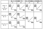
- the vehicle control apparatus has four control modes. First, the standard mode assuming a state where an appropriate turning state can be obtained while driving in a general urban area, and second, a state where a stable turning state can be obtained while actively driving a winding road etc. In sport mode, thirdly, comfort mode that assumes a state of driving with priority on ride comfort, such as when starting at a low vehicle speed, and fourthly, highway mode that assumes a state of traveling at high vehicle speed on highways with many straight lines is there.
- sport mode thirdly, comfort mode that assumes a state of driving with priority on ride comfort, such as when starting at a low vehicle speed
- highway mode that assumes a state of traveling at high vehicle speed on highways with many straight lines is there.
- priority is given to unsprung vibration suppression control by the unsprung vibration suppression control unit 34 while performing skyhook control by the skyhook control unit 33a.
- priority is given to driver input control by the driver input control unit 31, and skyhook control by the skyhook control unit 33a and unsprung vibration suppression control by the unsprung vibration suppression control unit 34 are performed.
- comfort mode the control for giving priority to the unsprung vibration damping control by the unsprung vibration damping control unit 34 is performed while performing the frequency sensitive control by the frequency sensitive control unit 33b.
- priority is given to driver input control by the driver input control unit 31, and control for adding the amount of unsprung vibration suppression control by the unsprung vibration control unit 34 to skyhook control by the skyhook control unit 33a is performed. To do.
- the adjustment of the attenuation coefficient in each mode will be described.
- FIG. 18 is a flowchart illustrating the attenuation coefficient arbitration process in the standard mode according to the first embodiment.
- step S1 it is determined whether or not the S / A attitude damping coefficient k2 is larger than the unsprung damping damping coefficient k4. If larger, the process proceeds to step S4 and k2 is set as the damping coefficient.
- step S2 a scalar amount ratio of the bull region is calculated based on the scalar amounts of the fur region, the leopard region, and the bull region described in the frequency response control unit 33b.
- step S3 it is determined whether or not the ratio of the bull area is equal to or greater than a predetermined value.
- the routine proceeds to step S5 and k4 is set.
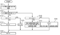
- FIG. 19 is a flowchart showing attenuation coefficient arbitration processing in the sport mode of the first embodiment.
- step S11 the four-wheel damping force distribution ratio is calculated based on the four-wheel driver input damping coefficient k1 set by the driver input control.
- the right front wheel driver input damping coefficient is k1fr
- the left front wheel driver input damping coefficient is k1fl
- the right rear wheel driver input damping coefficient is k1rr
- the left rear wheel driver input damping coefficient is k1rl
- xfl k1fl / (k1fr + k1fl + k1rr + k1rl)
- xrr k1rr / (k1fr + k1fl + k1rr + k1rl)
- xrl k1rl / (k1fr + k1fl + k1rr + k1rl)
- xrl k
- step S12 it is determined whether or not the damping force distribution ratio x is within a predetermined range (greater than ⁇ and smaller than ⁇ ). If it is within the predetermined range, it is determined that the distribution to each wheel is substantially equal, and the process proceeds to step S13. If any one is out of the predetermined range, the process proceeds to step S16. In step S13, it is determined whether or not the unsprung damping damping coefficient k4 is larger than the driver input damping coefficient k1. If it is determined that the unsprung damping damping coefficient k4 is larger, the process proceeds to step S15 and k4 is set as the first damping coefficient k. On the other hand, if it is determined that the unsprung damping damping coefficient k4 is equal to or less than the driver input damping coefficient k1, the process proceeds to step S14, and k1 is set as the first damping coefficient k.
- step S16 it is determined whether or not the unsprung damping damping coefficient k4 is the maximum value max that S / A3 can be set. If it is determined that the maximum value is max, the process proceeds to step S17, and otherwise, the process proceeds to step S18. move on.
- step S17 the maximum value of the four-wheel driver input damping coefficient k1 is the unsprung damping damping coefficient k4, and the damping coefficient that satisfies the damping force distribution ratio is calculated as the first damping coefficient k. In other words, a value that maximizes the damping coefficient while satisfying the damping force distribution rate is calculated.
- step S18 a damping coefficient that satisfies the damping force distribution ratio in a range where all the four-wheel driver input damping coefficients k1 are equal to or greater than k4 is calculated as the first damping coefficient k.
- a value that satisfies the damping force distribution ratio set by the driver input control and also satisfies the requirements of the unsprung vibration suppression control side is calculated.
- step S19 it is determined whether or not the first attenuation coefficient k set in each of the above steps is smaller than the S / A attitude attenuation coefficient k2 set by skyhook control. Since the damping coefficient requested on the side is larger, the process proceeds to step S20 and k2 is set. On the other hand, if it is determined that k is equal to or greater than k2, the process proceeds to step S21 and k is set.
- the damping force distribution rate required from the driver input control side is closely related to the vehicle body posture, and particularly because it is closely related to the driver's line-of-sight change due to the roll mode.
- the highest priority is to secure the damping force distribution ratio.
- the sky vehicle body posture can be maintained by selecting Skyhook control with select high.
- FIG. 20 is a flowchart illustrating the attenuation coefficient arbitration process in the comfort mode according to the first embodiment.
- step S30 it is determined whether or not the frequency sensitive damping coefficient k3 is larger than the unsprung damping damping coefficient k4. If it is determined that the frequency sensitive damping coefficient k3 is larger, the process proceeds to step S32 and the frequency sensitive damping coefficient k3 is set. On the other hand, if it is determined that the frequency sensitive damping coefficient k3 is equal to or less than the unsprung damping damping coefficient k4, the process proceeds to step S32 to set the unsprung damping damping coefficient k4.
- the comfort mode priority is given to unsprung resonance control that basically suppresses unsprung resonance.
- frequency sensitive control was performed as sprung mass damping control, and the optimum damping coefficient was set according to the road surface condition, so it was possible to achieve control that ensured riding comfort and lack of grounding feeling due to fluttering under the spring. Can be avoided by unsprung vibration suppression control.
- the attenuation coefficient may be switched according to the bull ratio of the frequency scalar quantity. As a result, the ride comfort can be further ensured in the super comfort mode.
- FIG. 21 is a flowchart illustrating the attenuation coefficient arbitration process in the highway mode according to the first embodiment. Since steps S11 to S18 are the same as the arbitration process in the sport mode, the description thereof is omitted.
- step S40 the S / A attitude attenuation coefficient k2 by the skyhook control is added to the first attenuation coefficient k that has been adjusted up to step S18, and is output.
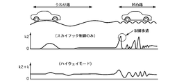
- FIG. 22 is a time chart showing a change in attenuation coefficient when traveling on a wavy road surface and an uneven road surface.
- the first damping coefficient k is always set as in the highway mode, a certain amount of damping force is always secured, and the vehicle body fluctuates even when the damping coefficient by the skyhook control is small. Such movement can be suppressed. Further, since it is not necessary to increase the skyhook control gain, it is possible to appropriately deal with road surface irregularities by using a normal control gain. In addition, since the skyhook control is performed with the first damping coefficient k set, unlike the damping coefficient limit, the damping coefficient decreasing process can be performed in the semi-active control region, and at the time of high-speed traveling It is possible to ensure a stable vehicle posture.
- FIG. 23 is a flowchart illustrating a mode selection process based on the running state in the attenuation coefficient arbitration unit of the first embodiment.
- step S50 it is determined whether or not the vehicle is in the straight traveling state based on the value of the steering angle sensor 7. If it is determined that the vehicle is traveling straight, the process proceeds to step S51. If it is determined that the vehicle is turning, the process proceeds to step S54. move on.
- step S51 it is determined based on the value of the vehicle speed sensor 8 whether or not the vehicle speed is equal to or higher than a predetermined vehicle speed VSP1 representing a high vehicle speed state.
- step S52 If it is determined that the vehicle speed is VSP1 or higher, the process proceeds to step S52 and the standard mode is selected. On the other hand, if it is determined that it is less than VSP1, the process proceeds to step S53 and the comfort mode is selected. In step S54, based on the value of the vehicle speed sensor 8, it is determined whether or not the vehicle speed is equal to or higher than a predetermined vehicle speed VSP1 representing a high vehicle speed state. On the other hand, if it is determined that it is less than VSP1, the process proceeds to step S56 to select the sport mode.
- the standard mode when driving at a high vehicle speed in a straight running state, the standard mode is selected to stabilize the vehicle body posture by skyhook control and to suppress the high frequency vibration such as leopard and bull. In addition, unsprung resonance can be suppressed. Further, when traveling at a low vehicle speed, by selecting the comfort mode, it is possible to suppress unsprung resonance while suppressing the input of vibrations such as leopard and bull to the occupant as much as possible.
- the highway mode is selected, so that it is controlled by the value obtained by adding the damping coefficient, so that basically a high damping force can be obtained.
- the sport mode is selected, so that the vehicle posture during turning is positively secured by driver input control, and unsprung resonance is suppressed while skyhook control is performed as appropriate. Can travel in a stable vehicle posture.
- the control example in which the driving state is detected and automatically switched is shown in the first embodiment.
- a changeover switch that can be operated by the driver is provided to select the driving mode. You may control to. As a result, ride comfort and turning performance according to the driving intention of the driver can be obtained.
- the sprung mass damping control units 101a and 33 or the skyhook control unit are used in the traveling state estimation units 100, 200, and 32 based on the wheel speeds detected by the wheel speed sensor 5.
- the stroke speed, bounce rate, roll rate, and pitch rate of each wheel used for the 201 skyhook control are estimated.
- the stroke speed and the sprung state are estimated from the wheel speed, a scene is assumed in which the estimation accuracy decreases due to various factors. For example, when traveling on a low ⁇ road, a slip is likely to occur, and it is difficult to determine whether or not the wheel speed fluctuation accompanying the slip is due to road surface unevenness.
- the wheel speed fluctuation amount due to changes in road surface unevenness and sprung state tends to be small, and it is difficult to distinguish from other noises.
- the fluctuation of the braking / driving torque causes the wheel speed fluctuation, it is difficult to distinguish the fluctuation from the sprung state or the stroke speed.
- the wheel speed fluctuates due to yaw rate or lateral acceleration in the non-linear region like the friction circle limit of the tire, making it difficult to distinguish from other noises.
- the estimation accuracy is lowered, for example, a place to be increased as a damping force may be set low, and it becomes difficult to stabilize the sprung state.
- the decrease in the estimated accuracy is merely a problem of accuracy, and it is not an abnormality such as a sensor failure or an actuator failure. Therefore, it can be said that it is desirable to continue the control within a possible range. Therefore, in the first embodiment, the estimated accuracy decrease detection unit 4a that detects when the estimated accuracy is reduced is provided, and when the estimated accuracy is reduced, at least performance equal to or higher than that of a general vehicle that does not perform vehicle system vibration control is ensured. However, by continuing the control as much as possible, it was decided to stabilize the sprung behavior accompanying the decrease in the estimation accuracy.
- FIG. 24 is a control block diagram illustrating an estimated accuracy decrease detection process according to the first embodiment.
- the estimated accuracy decrease detection unit 4a a plurality of accuracy decrease detection processes are executed based on various signals, and when the signal reception unit 400 detects accuracy decrease in any one of the processes, the accuracy decrease An accuracy decrease signal is output to the hold unit 401.
- the accuracy decrease hold unit 401 continuously turns on the accuracy decrease flag while receiving the accuracy decrease signal and even if the accuracy decrease signal is interrupted for a predetermined time (1 second in the first embodiment). And Thereby, the control state based on the incorrect state estimation value is avoided while suppressing frequent switching of the accuracy decrease flag.
- each accuracy fall detection process is demonstrated in order.
- an anti-skid brake control unit (hereinafter referred to as an ABS control unit) that detects the slip state of each wheel during braking and performs pressure increase / decrease control so that the slip rate is a predetermined value or less. ),
- a vehicle behavior control unit (hereinafter referred to as a VDC control unit) that controls the brake fluid pressure of a predetermined wheel so that the turning state (for example, yaw rate) of the vehicle becomes a target turning state, and when the vehicle starts.
- a traction control unit (hereinafter referred to as a TCS control unit) that performs brake pressure increase control and engine torque down control in order to suppress drive slip.
- the estimation accuracy may be lowered because the wheel speed fluctuation of each wheel is affected. Therefore, when the ABS flag, VDC flag, or TCS flag indicating that these controls are activated is turned on, a flag on signal is output to the brake control flag hold unit 410.
- the brake control flag hold unit 410 outputs an estimated accuracy decrease signal while receiving the flag on signal.
- the accuracy decrease signal is continuously output for a predetermined time (5 seconds in the first embodiment) set in advance from the falling edge of the flag-on signal. Thereby, even when the brake control flag is repeatedly turned on and off, the estimated accuracy lowering signal can be output stably.
- the first to third traveling state estimation units 100, 200, and 32 are used to detect a component that varies with the stroke of S / A3 when estimating the stroke speed from the wheel speed data. Wheel speed is calculated. This is because the difference between the reference wheel speed and the wheel speed sensor value is extracted as a fluctuation component accompanying the stroke.
- This reference wheel speed can ensure the accuracy of stroke speed estimation under the condition that no slip or the like occurs, but when slip occurs, it is possible to determine whether it is a fluctuation due to the stroke or a fluctuation in the wheel speed due to the slip. It becomes difficult.
- a low-pass filter (0.5 Hz in the first embodiment) on the lower frequency side than the vibration frequency generated by the stroke speed, sprung speed, etc. is applied to the reference wheel speed, and the reference wheel speed after this low-pass filter action is the distance between the wheels. In the case where there is variation, the wheel speed is changed due to slip and it is detected that the estimated accuracy is lowered.
- the reference wheel speed estimation unit 420 calculates the first wheel speed V0 that is the reference wheel speed of each wheel based on the vehicle body plan view model, as described in the reference wheel speed calculation unit of FIG.
- the wheel speed sensor value detected by the wheel speed sensor 5 is ⁇ (rad / s)
- the front wheel actual steering angle detected by the steering angle sensor 7 is ⁇ f (rad)
- the rear wheel actual steering angle is ⁇ r (rad )
- the vehicle body lateral speed is Vx
- the yaw rate detected by the integrated sensor 6 is ⁇ (rad / s)
- the vehicle speed estimated from the calculated reference wheel speed ⁇ 0 is V (m / s)
- the reference to be calculated Wheel speed is VFL, VFR, VRL, VRR
- front wheel tread is Tf
- rear wheel tread is Tr
- distance from vehicle center of gravity to front wheel is Lf
- distance from vehicle center of gravity to rear wheel is Lr.
- VFL (V-Tf / 2 ⁇ ⁇ ) cos ⁇ f + (Vx + Lf ⁇ ⁇ ) sin ⁇ f
- VFR (V + Tf / 2 ⁇ ⁇ ) cos ⁇ f + (Vx + Lf ⁇ ⁇ ) sin ⁇ f
- VRL (V ⁇ Tr / 2 ⁇ ⁇ ) cos ⁇ r + (Vx ⁇ Lr ⁇ ⁇ ) sin ⁇ r
- VRR (V + Tr / 2 ⁇ ⁇ ) cos ⁇ r + (Vx-Lr ⁇ ⁇ ) sin ⁇ r
- V is described as V0FL, V0FR, V0RL, V0RR (corresponding to the first wheel speed) as a value corresponding to each wheel.
- V0FL ⁇ VFL-Lf ⁇ ⁇ sin ⁇ f ⁇ / cos ⁇ f + Tf / 2 ⁇ ⁇
- V0FR ⁇ VFR-Lf ⁇ ⁇ sin ⁇ f ⁇ / cos ⁇ f-Tf / 2 ⁇ ⁇
- V0RL ⁇ VRL + Lr ⁇ ⁇ sin ⁇ r ⁇ / cos ⁇ r + Tr / 2 ⁇ ⁇
- V0RR ⁇ VRR + Lf ⁇ ⁇ sin ⁇ f ⁇ / cos ⁇ r-Tr / 2 ⁇ ⁇
- the difference determination unit 422 calculates the following values, respectively.
- df3 VOFL-VORL
- df4 VOFR ⁇ VORR ⁇ Warp component (diagonal difference)
- the reference wheel speed hold unit 423 continuously outputs the accuracy decrease signal while receiving the estimated accuracy decrease signal and until a predetermined time (2 seconds in the first embodiment) elapses from the end of reception. Thereby, even when the difference determination unit 422 repeatedly turns on and off the estimated accuracy decrease signal, the estimated accuracy decrease signal can be stably output.
- a plan view model is set to estimate the lateral acceleration Yg.
- Yg (VSP 2 / (1 + A ⁇ VSP 2 )) ⁇ ⁇ f
- A is a predetermined value.
- the roll rate is estimated from the lateral acceleration Yg estimated based on this relationship. At this time, in a situation where the estimation accuracy of the stroke speed is lowered due to the occurrence of slip or the like, the estimated value of the lateral acceleration deviates from the actual value.
- a low-pass filter (0.5 Hz in the first embodiment) on the lower frequency side than the vibration frequency generated by the stroke speed, sprung speed, etc. is applied to the estimated lateral acceleration, and the lateral acceleration after this low-pass filter action is the lateral acceleration.
- the estimated estimated lateral acceleration and estimated yaw rate and the sensor value detected by the integrated sensor 6 are converted into a region on the lower frequency side than the frequency region including the stroke speed and the sprung speed. Filter with a 0.5 Hz low-pass filter to extract the stationary component. Then, the difference determination unit 432 calculates the difference between the estimated value and the sensor value.
- the output of the estimated accuracy lowering signal is stopped when the predetermined value dfthi is equal to or less than a value obtained by multiplying 0.8.
- the plan view model hold unit 433 continuously outputs the accuracy decrease signal while receiving the estimated accuracy decrease signal and until a predetermined time (2 seconds in the first embodiment) elapses from the end of reception. Thereby, even when the difference determination unit 432 repeatedly turns on and off the estimated accuracy decrease signal, the estimated accuracy decrease signal can be stably output.
- shift determination unit 440 when the shift signal indicates a reverse range or a parking range, an accuracy decrease signal is continuously output to shift hold unit 441.
- the shift hold unit 441 continuously outputs an accuracy decrease signal until a predetermined time (1 second in the first embodiment) elapses from the end of reception of the estimated accuracy decrease signal from the viewpoint of preventing hunting associated with the shift operation. To do.
- the braking force release determination unit 450 determines whether or not the brake switch has been switched from on to off, and outputs an accuracy decrease signal to the brake switch hold unit 451 when it is determined that the switch has been switched.
- the brake switch hold unit 451 continuously outputs an accuracy decrease signal until a predetermined time (1 second in the first embodiment) elapses from the time when the brake switch is switched off.
- Tw Te ⁇ R TRQCVT ⁇ R AT ⁇ R FINAL ⁇ ⁇ TOTAL
- Tw is the wheel end drive torque
- Te is the engine torque
- R TRQCVT is the torque converter torque ratio
- R AT is the gear ratio of the automatic transmission
- R FINAL is the final gear ratio
- ⁇ TOTAL is the drive system efficiency.
- the wheel end braking torque varies during braking.
- the braking force is proportional to the wheel cylinder pressure (substantially the master cylinder pressure during normal braking when ABS or other control is not performed). The power is estimated.
- the low-pass filter 460 determines the wheel end driving torque in a lower frequency region than the frequency region including the stroke speed and sprung speed. Filter with a certain 0.5Hz low-pass filter to extract the stationary components. Then, the change rate of the wheel end driving torque is calculated by differentiation in the pseudo-differentiating unit 461. Then, the change rate determination unit 462 outputs an estimated accuracy lowering signal to the wheel end drive torque hold unit 463 when the calculated wheel end drive torque change rate is equal to or greater than a predetermined value dfthi set in advance.
- the output of the estimated accuracy lowering signal is stopped when the predetermined value dfthi is equal to or less than a value obtained by multiplying 0.8.
- the wheel end drive torque hold unit 463 continuously outputs the accuracy decrease signal while receiving the estimated accuracy decrease signal and until a predetermined time (1 second in the case of the first embodiment) elapses from the end of reception. .
- the rate-of-change determination unit 462 repeatedly turns on and off the estimated accuracy decrease signal, the estimated accuracy decrease signal can be stably output.
- each detection process is performed, and when any of these detects a decrease in accuracy, the estimated accuracy decrease flag is turned on, and an appropriate control process is executed when the accuracy decreases.
- the control process at the time of estimation accuracy fall is demonstrated.
- the estimated accuracy decrease detection control unit 5a When the estimated accuracy decrease flag is turned on, that is, when the estimated accuracy decrease of the stroke speed is detected, the estimated accuracy decrease detection control unit 5a outputs the engine attitude control amount as zero to the engine control unit 102. . Further, when the estimated accuracy lowering flag is turned on, the estimated accuracy lowering control unit 5a outputs the brake attitude control amount as zero to the brake control unit 202. At this time, the brake control unit 202 gradually decreases the brake posture control amount so that the brake posture control amount smoothly decreases to zero over a certain transition time (for example, 1 second).
- the sprung mass damping control by the engine 1 and the brake 20 is stopped while a decrease in the estimated accuracy of the stroke speed is detected.
- the stroke speed is estimated from the fluctuation in the predetermined frequency region of the wheel speed, and the sprung behavior control using the engine 1 and the brake 20 is performed according to the stroke speed, so the estimated accuracy of the stroke speed is reduced.
- the sprung behavior may be disturbed due to deterioration of controllability.
- FIG. 25 is a control block diagram illustrating the configuration of the estimation accuracy decrease detection control unit 5a according to the first embodiment.
- the estimated accuracy decrease flag, the vehicle speed VSP detected by the vehicle speed sensor 8, and the value of the vehicle speed VSP before one sampling period (one clock) are input.
- the vehicle speed calculation unit 501 outputs the vehicle speed VSP detected by the vehicle speed sensor 8 to the delay element 502 when the estimated accuracy decrease flag is turned off.
- the flag is turned off.
- the vehicle speed immediately before one sampling period that is, the vehicle speed immediately before the decrease in the estimation accuracy of the stroke speed is detected is output to the attenuation coefficient setting unit 503.
- the delay element 502 delays a signal for one clock.
- the attenuation coefficient setting unit 503 inputs the vehicle speed immediately before the decrease in the estimated accuracy of the stroke speed, the outside air temperature detected by the temperature sensor 14, and the current control mode are input, and the attenuation coefficient k5 when the estimated accuracy decreases. Is output. A method for setting the attenuation coefficient k5 will be described later.
- the damping force control amount computing unit 504 computes a control signal for S / A3 based on the damping coefficient k5 and a predetermined virtual stroke speed.
- the virtual stroke speed is a fixed value
- FIG. 26 is an explanatory diagram illustrating a method for setting the attenuation coefficient when the estimated accuracy is reduced in the attenuation coefficient setting unit according to the first embodiment.
- the damping coefficient k5 is basically a value proportional to the vehicle speed (the vehicle speed immediately before the drop in estimated accuracy of the stroke speed is detected), and the damping coefficient of the front wheel side Fr is the same as the damping coefficient of the rear wheel side Rr at the same vehicle speed. The characteristics should be higher.
- the attenuation coefficient k5 is a value corresponding to the control mode. Specifically, the highest value is set in the sport mode and the highway mode, and the lowest value is set in the comfort mode. In the standard mode, an intermediate value between the sports mode (highway mode) and the comfort mode is set.
- the attenuation coefficient k5 in the sport mode and the highway mode is an upper limit attenuation coefficient that does not transmit vibration in the horizontal region (3 to 6 Hz) to the occupant.
- the attenuation coefficient setting unit 504 determines the attenuation coefficient when the outside air temperature is outside the predetermined range (for example, outside air temperature ⁇ 5 ° C. or outside air temperature ⁇ 30 ° C.), and the outside air temperature is within the predetermined range (for example, A value higher than the attenuation coefficient in the case of 5 ° C. ⁇ outside air temperature ⁇ 30 ° C. (the same attenuation coefficient as in the standard mode) is set.
- vehicle speed sensitive control is performed in which the damping force of S / A3 is a fixed damping force according to the control mode.
- the damping force of S / A3 is a fixed damping force according to the control mode.
- the fixed damping force is determined from the vehicle speed immediately before the estimated accuracy drop is detected, and it does not depend on the stroke speed, which is highly likely to be erroneously estimated. Due to the transition to a stable control state, it is possible to suppress the deterioration of the riding comfort performance and the instability of the behavior.
- the damping coefficient k5 is set from the vehicle speed immediately before the estimated accuracy decrease is detected, and the fixed damping force is determined based on the damping coefficient k5 and a predetermined virtual stroke speed (0.1 m / s). At this time, the damping coefficient k5 is set to a higher value as the vehicle speed immediately before the estimated accuracy decrease is detected, so that an optimum damping force that matches the vehicle speed is obtained. That is, it is possible to achieve both of ensuring the riding comfort in the low vehicle speed range and ensuring the steering stability in the high vehicle speed range.
- the damping coefficient k5 is set to a higher value in the order of the sport mode, the highway mode, the standard mode, and the comfort mode, a fixed damping force that matches the control mode can be set.
- the damping force is increased to give priority to steering stability
- in comfort mode the damping force is reduced to give priority to riding comfort
- in standard mode steering stability and riding comfort are set with damping force in the middle.
- the fixed damping force of the front wheels is made larger than the fixed damping force of the rear wheels, so the nose dive can be suppressed and the steer tendency can be changed to an understeer tendency, which improves the stability of turning behavior. It can be secured.
- the outside air temperature is outside the predetermined range (outside air temperature ⁇ 5 ° C. or outside air temperature ⁇ 30 ° C.)
- the outside air The fixed damping force is made larger than when the temperature is outside the predetermined range (outside air temperature ⁇ 5 ° C. or outside air temperature ⁇ 30 ° C.).
- reverse steer means that the steering tendency changes from an understeer tendency to an oversteer tendency during turning. Therefore, in the first embodiment, in the comfort mode, the fixed damping force when traveling on a low ⁇ road is made larger than the fixed damping force when traveling on a high ⁇ road. As a result, it is possible to suppress a reduction in the ground contact load of the rear tire and to suppress the generation of a nose dive. Therefore, it is possible to prevent the steering tendency from becoming an oversteer tendency and to ensure the stability of the turning behavior.
- the fixed damping force when traveling in the low ⁇ state is set to the same value as the fixed damping force when traveling in the high ⁇ state.
- the fixed damping force is the maximum fixed damping force that does not transmit vibrations that move to the occupants, thus improving steering stability while suppressing deterioration in riding comfort. Can do.
- the command current value (command current value at the time of estimation accuracy decrease) is output from the control unit 5a when the estimated accuracy decrease is detected
- the attenuation adjusted by the attenuation coefficient arbitration unit 35b instead of the command current value (normal command current value) based on the coefficient and the stroke speed
- the command current value when the estimated accuracy is reduced is output to S / A3.
- the command current value is gradually changed so that the command current value smoothly transitions from the current command current value over the predetermined transition time to the command current value when the estimated accuracy decreases.
- the transition time is set to a time of at least a period (for example, 0.5 Hz) equal to or less than the sprung resonance (1.2 Hz), for example, 1 second.
- Example 1 has the following effects.
- Engine 1 vehicle power source
- S / A 3 dampping force variable shock absorber
- wheel speed sensor 5 wheel speed detecting means
- a first traveling state estimation unit 100 that estimates a sprung state based on information in a predetermined frequency region of the wheel speed detected by the wheel speed sensor 5, a third traveling state estimation unit 32 (sprung state estimation means),
- An engine controller 1a and an S / A controller 3a actuator attitude control means for controlling the actuator so that the estimated sprung state becomes a target sprung state, a first traveling state estimation unit 100, and a third traveling state estimation.
- the estimation accuracy decrease detection unit 4a (estimation accuracy decrease detection means) that detects a decrease in the estimation accuracy of the unit 32 and the estimation accuracy decrease detection unit 4a reduce the estimation accuracy.
- a control unit 5a (limit control means) for detecting a decrease in estimated accuracy for continuing the sprung mass damping control by the S / A 3 while prohibiting the sprung mass damping control by the engine 1 is provided. . Therefore, it can be detected that the estimated accuracy of the sprung state has been lowered, and it is possible to avoid continuing control while the estimated accuracy is reduced.
- control unit 5a at the time of the estimated accuracy decrease detection prohibits the control by the engine 1 when the estimated accuracy is decreased, thereby suppressing the torque fluctuation caused by the erroneous control, and the vehicle body posture by continuing the control by the S / A3.
- Can be achieved if the actuator that contributes to the longitudinal acceleration of the vehicle, such as braking / driving torque, performs torque control in the longitudinal direction using incorrect information or information with low accuracy, inadvertent acceleration / deceleration unrelated to the sprung state May occur.
- the possibility of giving the driver a sense of incongruity can be avoided by stopping the control that affects the braking / driving torque in the front-rear direction.
- Brake 20 (friction brake) and S / A3 (damping force variable shock absorber) which are actuators for performing sprung mass damping control, wheel speed sensor 5 (wheel speed detecting means) for detecting wheel speed, and wheels
- a second traveling state estimating unit 200 for estimating a sprung state based on information in a predetermined frequency region of the wheel speed detected by the speed sensor 5, a third traveling state estimating unit 32 (a sprung state estimating means), and the estimation
- the brake controller 2a and the S / A controller 3a (actuator attitude control means) for controlling the actuator so that the sprung state thus obtained becomes the target sprung state, the second traveling state estimating unit 200, and the third traveling state estimating unit 32.
- Estimated accuracy degradation detector 4a (estimated accuracy degradation detector) for detecting a decrease in estimated accuracy of the system and estimated accuracy degradation detector 4a
- a control unit 5a (limit control means) for detecting a decrease in estimated accuracy for continuing the sprung mass damping control by the S / A 3 while prohibiting the sprung mass damping control by the brake 20 when the bottom is detected. It was. Therefore, it can be detected that the estimated accuracy of the sprung state has been lowered, and it is possible to avoid continuing control while the estimated accuracy is reduced.
- control unit 5a at the time of detection of the decrease in estimated accuracy prohibits the control by the brake 20 when the accuracy of the estimation is decreased, thereby suppressing the torque fluctuation due to erroneous control, and the vehicle body posture by continuing the control by S / A3.
- Engine 1 brake 20 and S / A 3 which are actuators for performing sprung mass damping control, wheel speed sensor 5 for detecting wheel speed, and wheel speed detected by wheel speed sensor 5 in a predetermined frequency region
- a second traveling state estimating unit 200 for estimating a sprung state based on the information
- a third traveling state estimating unit 32 (a sprung state estimating means), and the estimated sprung state to be a target sprung state.
- the engine controller 1a, the brake controller 2a, and the S / A controller 3a actuator attitude control means that control the actuator, the first traveling state estimation unit 100, the second traveling state estimation unit 200, and the third traveling state estimation unit 32 are estimated.
- the estimated accuracy decrease detection unit 4a (estimated accuracy decrease detection means) for detecting a decrease in accuracy and the estimated accuracy decrease detection unit 4a reduce the estimated accuracy. Is detected, while the sprung mass damping control by the S / A 3 is continued while the sprung mass damping control by the engine 1 and the brake 20 is prohibited, Equipped with. Therefore, it can be detected that the estimated accuracy of the sprung state has been lowered, and it is possible to avoid continuing control while the estimated accuracy is reduced.
- the control unit 5a when the estimated accuracy decrease is detected, torque fluctuation due to erroneous control can be suppressed, and control by S / A3 can be continued. Can stabilize the body posture.
- the actuator that contributes to the longitudinal acceleration of the vehicle such as braking / driving torque
- inadvertent acceleration / deceleration unrelated to the sprung state May occur.
- the possibility of giving the driver a sense of incongruity can be avoided by stopping the control that affects the braking / driving torque in the front-rear direction.
- the S / A controller 3a has a highway mode, a sports mode, a standard mode, and a comfort mode (a plurality of control modes) in which different damping force control ranges are set for a certain stroke speed, and detection of a decrease in estimated accuracy.
- the hour control unit 5a transits to a fixed damping force corresponding to the control mode when the estimated accuracy detection unit 4a detects a decrease in the estimated accuracy. For example, when a decrease in estimated accuracy is detected during traveling in the comfort mode, it is assumed that it is difficult to ensure sufficient stability as a vehicle state when the attenuation coefficient is fixed to a low value. Therefore, in this case, stability can be secured by fixing the damping force higher than the damping force set in the comfort mode.
- the estimated accuracy decrease detection control unit 5a makes a transition to a fixed damping force according to the vehicle speed immediately before the estimated accuracy detection unit 4a detects a decrease in estimated accuracy. Therefore, the fixed damping force can be set based on the vehicle speed actually used in each control mode rather than the vehicle speed when the estimated accuracy is lowered, and the stability of the vehicle can be improved.
- the engine 1 and the brake 20, which are a plurality of actuators including S / A3, are controlled so as to be in a state, and when a decrease in the estimated accuracy of the sprung state is detected, the sprung mass damping control by S / A3 is continued.
- an engine controller 1a, a brake controller 2a, and an S / A controller 3a that prohibit the sprung mass damping control by the engine 1 and the brake 20 which are other actuators are provided.
- the engine 1 and the brake 20 when the estimated accuracy is reduced by the estimated accuracy decrease detection control unit 5a, it is possible to suppress torque fluctuations due to erroneous control and to continue the control by S / A3.
- Can stabilize the body posture That is, if the actuator that contributes to the longitudinal acceleration of the vehicle, such as braking / driving torque, performs torque control in the longitudinal direction using incorrect information or information with low accuracy, inadvertent acceleration / deceleration unrelated to the sprung state May occur.
- the possibility of giving the driver a sense of incongruity can be avoided by stopping the control that affects the braking / driving torque in the front-rear direction.
- the sprung state is estimated, and the engine 1 and the brake 20 that are a plurality of actuators including the S / A 3 are controlled so that the sprung state becomes the target sprung state, and a decrease in the estimated accuracy of the sprung state is detected.
- the sprung mass damping control by the engine 1 or the brake 20 as another actuator is prohibited while continuing the sprung mass damping control by S / A3.
- the engine 1 and the brake 20 when the estimated accuracy is reduced by the estimated accuracy decrease detection control unit 5a, it is possible to suppress torque fluctuations due to erroneous control and to continue the control by S / A3.
- Can stabilize the body posture That is, if the actuator that contributes to the longitudinal acceleration of the vehicle, such as braking / driving torque, performs torque control in the longitudinal direction using incorrect information or information with low accuracy, inadvertent acceleration / deceleration unrelated to the sprung state May occur.
- the possibility of giving the driver a sense of incongruity can be avoided by stopping the control that affects the braking / driving torque in the front-rear direction.
Abstract
This vehicle control device estimates the state on a spring on the basis of a set of information pertaining to a predetermined frequency region of the wheel speed detected by means of a wheel speed detection means, controls multiple actuators including a damping force variable shock absorber such that the estimated state on the spring reaches a target state on the spring, and prohibits the damping on the spring from being controlled by other actuators while allowing the damping force variable shock absorber to continue to control the damping on the spring when deterioration in the estimation accuracy of the state on the spring was detected.
Description
本発明は、車両の状態を制御する制御装置及び制御方法に関する。
The present invention relates to a control device and a control method for controlling the state of a vehicle.
特許文献1には、車輪速の所定周波数領域における変動からストローク速度を推定し、ストローク速度に応じて減衰力可変ショックアブソーバの減衰力を変更してばね上挙動を制御する技術が開示されている。
Patent Document 1 discloses a technique for estimating the stroke speed from the fluctuation of the wheel speed in a predetermined frequency region and changing the damping force of the damping force variable shock absorber according to the stroke speed to control the sprung behavior. .
しかしながら、上記従来技術にあっては、車輪速の所定周波数領域内に外乱が生じると、ストローク速度の推定確度が低下するという問題があった。
本発明は、上記問題に着目してなされたもので、ばね上状態の推定確度の低下を検知可能な車両の制御装置及び制御方法を提供することを目的とする。 However, in the above-described prior art, there is a problem that the estimation accuracy of the stroke speed is lowered when a disturbance occurs in a predetermined frequency region of the wheel speed.
The present invention has been made paying attention to the above problem, and an object of the present invention is to provide a vehicle control device and a control method capable of detecting a decrease in the estimated accuracy of the sprung state.
上記目的を達成するため、本発明の車両の制御装置では、車輪速検出手段により検出された車輪速の所定周波数領域における情報に基づいてばね上状態を推定し、このばね上状態が目標ばね上状態となるように減衰力可変ショックアブソーバを含む複数のアクチュエータを制御すると共に、ばね上状態の推定確度低下を検知した場合には、減衰力可変ショックアブソーバによるばね上制振制御を継続しつつ他のアクチュエータによるばね上制振制御を禁止することとした。
In order to achieve the above object, in the vehicle control apparatus of the present invention, the sprung state is estimated based on information in the predetermined frequency region of the wheel speed detected by the wheel speed detecting means, and this sprung state is the target sprung state. In addition to controlling multiple actuators including a damping force variable shock absorber so as to be in a state, and when detecting a decrease in the estimated accuracy of the sprung state, while continuing the sprung mass damping control by the variable damping force shock absorber, The sprung mass damping control by the actuator is prohibited.
よって、ばね上状態の推定確度が低下したことを検知することができ、推定確度が低下したままで制御を継続することを回避できる。また、推定確度低下時に減衰力可変ショックアブソーバ以外のアクチュエータによる制御を禁止することで誤った制御に伴うトルク変動を抑制することができ、減衰力可変ショックアブソーバによる制御を継続することで車体姿勢の安定化を達成できる。
すなわち、他のアクチュエータが制駆動トルクのように車両の前後加速度に寄与する場合、誤った情報もしくは確度の低い情報を用いて前後方向にトルク制御を行うと、ばね上状態と関係の無い不用意な加減速が生じるおそれがある。これに対し、前後方向の制駆動トルクに影響を与える制御を中止することで、運転者に違和感を与えるおそれを回避できる。 Therefore, it can be detected that the estimated accuracy of the sprung state has been lowered, and it is possible to avoid continuing control while the estimated accuracy is reduced. In addition, torque fluctuations associated with incorrect control can be suppressed by prohibiting control by actuators other than damping force variable shock absorbers when the estimated accuracy is reduced, and vehicle body posture can be controlled by continuing control by damping force variable shock absorbers. Stabilization can be achieved.
That is, when other actuators contribute to the longitudinal acceleration of the vehicle, such as braking / driving torque, if the torque control is performed in the longitudinal direction using incorrect information or information with low accuracy, carelessness that is not related to the sprung state is inadvertent. Acceleration and deceleration may occur. On the other hand, the possibility of giving the driver a sense of incongruity can be avoided by stopping the control that affects the braking / driving torque in the front-rear direction.
1 エンジン
1a エンジンコントローラ(エンジン制御部)
2 ブレーキコントロールユニット
2a ブレーキコントローラ(ブレーキ制御部)
3 S/A(減衰力可変ショックアブソーバ)
3a S/Aコントローラ
5 車輪速センサ
6 一体型センサ
7 舵角センサ
8 車速センサ
20 ブレーキ
31 ドライバ入力制御部
32 走行状態推定部
33 ばね上制振制御部
33a スカイフック制御部
33b 周波数感応制御部
34 ばね下制振制御部
35 減衰力制御部
331 第1目標姿勢制御量演算部
332 エンジン姿勢制御量演算部
333 第2目標姿勢制御量演算部
334 ブレーキ姿勢制御量演算部
335 第3目標姿勢制御量演算部
336 ショックアブソーバ姿勢制御量演算部
1Engine 1a Engine controller (engine control unit)
2Brake control unit 2a Brake controller (brake control unit)
3 S / A (Damping force variable shock absorber)
3a S /A controller 5 Wheel speed sensor 6 Integrated sensor 7 Steering angle sensor 8 Vehicle speed sensor 20 Brake 31 Driver input control unit 32 Running state estimation unit 33 Sprung vibration suppression control unit 33a Skyhook control unit 33b Frequency response control unit 34 Unsprung vibration suppression control unit 35 Damping force control unit 331 First target posture control amount calculation unit 332 Engine posture control amount calculation unit 333 Second target posture control amount calculation unit 334 Brake posture control amount calculation unit 335 Third target posture control amount Calculation unit 336 Shock absorber attitude control amount calculation unit
1a エンジンコントローラ(エンジン制御部)
2 ブレーキコントロールユニット
2a ブレーキコントローラ(ブレーキ制御部)
3 S/A(減衰力可変ショックアブソーバ)
3a S/Aコントローラ
5 車輪速センサ
6 一体型センサ
7 舵角センサ
8 車速センサ
20 ブレーキ
31 ドライバ入力制御部
32 走行状態推定部
33 ばね上制振制御部
33a スカイフック制御部
33b 周波数感応制御部
34 ばね下制振制御部
35 減衰力制御部
331 第1目標姿勢制御量演算部
332 エンジン姿勢制御量演算部
333 第2目標姿勢制御量演算部
334 ブレーキ姿勢制御量演算部
335 第3目標姿勢制御量演算部
336 ショックアブソーバ姿勢制御量演算部
1
2
3 S / A (Damping force variable shock absorber)
3a S /
〔実施例1〕
図1は実施例1の車両の制御装置を表すシステム概略図である。車両には、動力源であるエンジン1と、各輪に摩擦力による制動トルクを発生させるブレーキ20(以下、個別の輪に対応するブレーキを表示するときには右前輪ブレーキ:20FR、左前輪ブレーキ:20FL、右後輪ブレーキ:20RR、左後輪ブレーキ:20RLと記載する。)と、各輪と車体との間に設けられ減衰力を可変に制御可能なショックアブソーバ3(以下、S/Aと記載する。個別の輪に対応するS/Aを表示するときには右前輪S/A:3FR、左前輪S/A:3FL、右後輪S/A:3RR、左後輪S/A:3RLと記載する。)と、を有する。 [Example 1]
FIG. 1 is a system schematic diagram illustrating a vehicle control apparatus according to the first embodiment. The vehicle includes anengine 1 that is a power source and a brake 20 that generates braking torque due to friction force on each wheel (hereinafter, when displaying brakes corresponding to individual wheels, right front wheel brake: 20FR, left front wheel brake: 20FL). Right rear wheel brake: 20RR, left rear wheel brake: 20RL), and shock absorber 3 (hereinafter referred to as S / A) provided between each wheel and the vehicle body and capable of variably controlling the damping force. When displaying S / A corresponding to an individual wheel, right front wheel S / A: 3FR, left front wheel S / A: 3FL, right rear wheel S / A: 3RR, left rear wheel S / A: 3RL And).
図1は実施例1の車両の制御装置を表すシステム概略図である。車両には、動力源であるエンジン1と、各輪に摩擦力による制動トルクを発生させるブレーキ20(以下、個別の輪に対応するブレーキを表示するときには右前輪ブレーキ:20FR、左前輪ブレーキ:20FL、右後輪ブレーキ:20RR、左後輪ブレーキ:20RLと記載する。)と、各輪と車体との間に設けられ減衰力を可変に制御可能なショックアブソーバ3(以下、S/Aと記載する。個別の輪に対応するS/Aを表示するときには右前輪S/A:3FR、左前輪S/A:3FL、右後輪S/A:3RR、左後輪S/A:3RLと記載する。)と、を有する。 [Example 1]
FIG. 1 is a system schematic diagram illustrating a vehicle control apparatus according to the first embodiment. The vehicle includes an
エンジン1は、エンジン1から出力されるトルクを制御するエンジンコントローラ(以下、エンジン制御部とも言う。動力源制御手段に相当)1aを有し、エンジンコントローラ1aは、エンジン1のスロットルバルブ開度や、燃料噴射量、点火タイミング等を制御することで、所望のエンジン運転状態(エンジン回転数やエンジン出力トルク)を制御する。また、ブレーキ20は、各輪のブレーキ液圧を走行状態に応じて制御可能なブレーキコントロールユニット2から供給される液圧に基づいて制動トルクを発生する。ブレーキコントロールユニット2は、ブレーキ20の発生する制動トルクを制御するブレーキコントローラ(以下、ブレーキ制御部とも言う)2aを有し、運転者のブレーキペダル操作によって発生するマスタシリンダ圧、もしくは内蔵されたモータ駆動ポンプにより発生するポンプ圧を液圧源とし、複数の電磁弁の開閉動作によって各輪のブレーキ20に所望の液圧を発生させる。
The engine 1 includes an engine controller (hereinafter also referred to as an engine control unit, which corresponds to power source control means) 1a that controls torque output from the engine 1, and the engine controller 1a is configured to By controlling the fuel injection amount, ignition timing, etc., the desired engine operating state (engine speed and engine output torque) is controlled. Further, the brake 20 generates a braking torque based on the hydraulic pressure supplied from the brake control unit 2 that can control the brake hydraulic pressure of each wheel according to the traveling state. The brake control unit 2 includes a brake controller (hereinafter also referred to as a brake control unit) 2a for controlling a braking torque generated by the brake 20, and a master cylinder pressure generated by a driver's brake pedal operation or a built-in motor. A pump pressure generated by the drive pump is used as a hydraulic pressure source, and a desired hydraulic pressure is generated in the brake 20 of each wheel by opening and closing operations of a plurality of solenoid valves.
S/A3は、車両のばね下(アクスルや車輪等)とばね上(車体等)との間に設けられたコイルスプリングの弾性運動を減衰する減衰力発生装置であり、アクチュエータの作動により減衰力を可変に構成されている。S/A3は、流体が封入されたシリンダと、このシリンダ内をストロークするピストンと、このピストンの上下に形成された流体室の間の流体移動を制御するオリフィスとを有する。更に、このピストンには複数種のオリフィス径を有するオリフィスが形成され、S/Aアクチュエータの作動時には、複数種のオリフィスから制御指令に応じたオリフィスが選択される。これにより、オリフィス径に応じた減衰力を発生することができる。例えば、オリフィス径が小さければピストンの移動は制限されやすいため、減衰力が高くなり、オリフィス径が大きければピストンの移動は制限されにくいため、減衰力は小さくなる。
S / A3 is a damping force generator that attenuates the elastic motion of a coil spring provided between a vehicle unsprung (axle, wheel, etc.) and a sprung (vehicle body, etc.). It is configured to be variable. The S / A 3 includes a cylinder in which fluid is sealed, a piston that strokes in the cylinder, and an orifice that controls fluid movement between fluid chambers formed above and below the piston. Furthermore, orifices having a plurality of types of orifice diameters are formed in the piston, and an orifice corresponding to a control command is selected from the plurality of types of orifices when the S / A actuator is operated. Thereby, the damping force according to the orifice diameter can be generated. For example, if the orifice diameter is small, the movement of the piston is easily restricted, so that the damping force is high. If the orifice diameter is large, the movement of the piston is difficult to be restricted, and thus the damping force is small.
尚、オリフィス径の選択以外にも、例えばピストンの上下に形成された流体を接続する連通路上に電磁制御弁を配置し、この電磁制御弁の開閉量を制御することで減衰力を設定してもよく、特に限定しない。S/A3は、S/A3の減衰力を制御するS/Aコントローラ3a(減衰力制御手段に相当)を有し、S/Aアクチュエータによりオリフィス径を動作させて減衰力を制御する。
In addition to the selection of the orifice diameter, for example, an electromagnetic control valve is arranged on the communication path connecting fluids formed above and below the piston, and the damping force is set by controlling the opening / closing amount of the electromagnetic control valve. There is no particular limitation. The S / A 3 has an S / A controller 3a (corresponding to damping force control means) that controls the damping force of the S / A 3, and controls the damping force by operating the orifice diameter by the S / A actuator.
また、各輪の車輪速を検出する車輪速センサ5(以下、個別の輪に対応する車輪速を表示するときには右前輪車輪速:5FR、左前輪車輪速:5FL、右後輪車輪速:5RR、左後輪車輪速:5RLと記載する。)と、車両の重心点に作用する前後加速度、ヨーレイト及び横加速度を検出する一体型センサ6と、運転者のステアリング操作量である操舵角を検出する舵角センサ7と、車速を検出する車速センサ8と、エンジントルクを検出するエンジントルクセンサ9と、エンジン回転数を検出するエンジン回転数センサ10と、マスタシリンダ圧を検出するマスタ圧センサ11と、ブレーキペダル操作が行なわれるとオン状態信号を出力するブレーキスイッチ12と、アクセルペダル開度を検出するアクセル開度センサ13と、外気温度を検出する温度センサ14と、を有する。これら各種センサの信号は、必要に応じてエンジンコントローラ1a,ブレーキコントローラ2a及びS/Aコントローラ3aに入力される。尚、一体型センサ6の配置は車両の重心位置でもよいし、それ以外の場所であっても、重心位置における各種値が推定可能な構成であればよく、特に限定しない。また、一体型である必要は無く、個別にヨーレイト、前後加速度及び横加速度を検出する構成としてもよい。
Further, a wheel speed sensor 5 for detecting the wheel speed of each wheel (hereinafter, when displaying the wheel speed corresponding to each wheel, right front wheel speed: 5FR, left front wheel speed: 5FL, right rear wheel speed: 5RR. , Left rear wheel speed: 5RL)), an integrated sensor 6 for detecting longitudinal acceleration, yaw rate and lateral acceleration acting on the center of gravity of the vehicle, and a steering angle which is a steering operation amount of the driver is detected. Steering angle sensor 7, vehicle speed sensor 8 for detecting vehicle speed, engine torque sensor 9 for detecting engine torque, engine speed sensor 10 for detecting engine speed, and master pressure sensor 11 for detecting master cylinder pressure. A brake switch 12 that outputs an on-state signal when the brake pedal is operated, an accelerator opening sensor 13 that detects an accelerator pedal opening, and an outside air temperature A temperature sensor 14 for detecting a. The signals from these various sensors are input to the engine controller 1a, the brake controller 2a, and the S / A controller 3a as necessary. The arrangement of the integrated sensor 6 may be at the center of gravity of the vehicle, or may be any place other than that as long as various values at the center of gravity can be estimated. Moreover, it is not necessary to be an integral type, and a configuration in which yaw rate, longitudinal acceleration, and lateral acceleration are individually detected may be employed.
(車両の制御装置の全体構成)
実施例1の車両の制御装置にあっては、ばね上に生じる振動状態を制御するために、3つのアクチュエータを使用する。このとき、それぞれの制御がばね上状態を制御するため、相互干渉が問題となる。また、エンジン1によって制御可能な要素と、ブレーキ20によって制御可能な要素と、S/A3によって制御可能な要素はそれぞれ異なり、これらをどのように組み合わせて制御するべきかが問題となる。
例えば、ブレーキ20はバウンス運動とピッチ運動の制御が可能であるが、両方を行なうと減速感が強く運転者に違和感を与えやすい。また、S/A3はロール運動とバウンス運動とピッチ運動の全てを制御可能であるが、S/A3によって全ての制御を広い範囲で行う場合、S/A3の製造コストの上昇を招き、また、減衰力が高くなる傾向があることから路面側からの高周波振動が入力されやすく、やはり運転者に違和感を与えやすい。言い換えると、ブレーキ20による制御は高周波振動の悪化を招くことは無いが減速感の増大を招き、S/A3による制御は減速感を招くことは無いが高周波振動の入力を招くというトレードオフが存在する。 (Overall configuration of vehicle control device)
In the vehicle control apparatus of the first embodiment, three actuators are used to control the vibration state generated on the spring. At this time, since each control controls the sprung state, mutual interference becomes a problem. In addition, the elements that can be controlled by theengine 1, the elements that can be controlled by the brake 20, and the elements that can be controlled by the S / A 3 are different from each other, and how to control them in combination is a problem.
For example, thebrake 20 can control a bounce motion and a pitch motion, but if both are performed, a feeling of deceleration is strong and a driver is likely to feel uncomfortable. In addition, S / A3 can control all of roll motion, bounce motion and pitch motion. However, when all control is performed by S / A3 in a wide range, the production cost of S / A3 is increased. Since the damping force tends to increase, high-frequency vibrations from the road surface side are easily input, and the driver is likely to feel uncomfortable. In other words, there is a trade-off that the control by the brake 20 does not cause deterioration of the high frequency vibration but increases the feeling of deceleration, and the control by the S / A3 does not cause the feeling of deceleration but invites the input of high frequency vibration. To do.
実施例1の車両の制御装置にあっては、ばね上に生じる振動状態を制御するために、3つのアクチュエータを使用する。このとき、それぞれの制御がばね上状態を制御するため、相互干渉が問題となる。また、エンジン1によって制御可能な要素と、ブレーキ20によって制御可能な要素と、S/A3によって制御可能な要素はそれぞれ異なり、これらをどのように組み合わせて制御するべきかが問題となる。
例えば、ブレーキ20はバウンス運動とピッチ運動の制御が可能であるが、両方を行なうと減速感が強く運転者に違和感を与えやすい。また、S/A3はロール運動とバウンス運動とピッチ運動の全てを制御可能であるが、S/A3によって全ての制御を広い範囲で行う場合、S/A3の製造コストの上昇を招き、また、減衰力が高くなる傾向があることから路面側からの高周波振動が入力されやすく、やはり運転者に違和感を与えやすい。言い換えると、ブレーキ20による制御は高周波振動の悪化を招くことは無いが減速感の増大を招き、S/A3による制御は減速感を招くことは無いが高周波振動の入力を招くというトレードオフが存在する。 (Overall configuration of vehicle control device)
In the vehicle control apparatus of the first embodiment, three actuators are used to control the vibration state generated on the spring. At this time, since each control controls the sprung state, mutual interference becomes a problem. In addition, the elements that can be controlled by the
For example, the
そこで、実施例1の車両の制御装置にあっては、これらの課題を総合的に判断し、それぞれの制御特性として有利な点を活かしつつ、相互の弱点を補完しあう制御構成を実現することで、安価でありながらも制振能力に優れた車両の制御装置を実現するために、主に、以下に列挙する点を考慮して全体の制御システムを構築した。
(1)エンジン1及びブレーキ20による制御を並行して行うことで、S/A3による制御量を抑制する。
(2)ブレーキ20の制御対象運動をピッチ運動に限定することで、ブレーキ20による制御での減速感を解消する。
(3)エンジン1及びブレーキ20による制御量を実際に出力可能な制御量よりも制限して出力することで、S/A3での負担を低減しつつ、エンジン1やブレーキ20の制御に伴って生じる違和感を抑制する。
(4)全てのアクチュエータによりスカイフック制御を行う。このとき、一般にスカイフック制御に必要とされるストロークセンサやばね上上下加速度センサ等を使用することなく、全ての車両に搭載されている車輪速センサを利用して安価な構成でスカイフック制御を実現する。
(5)S/A3によるばね上制御を行なう際、スカイフック制御のようなベクトル制御では対応が困難な高周波振動の入力に対し、新たにスカラー制御(周波数感応制御)を導入する。
(6)走行状態に応じて、S/A3が実現する制御状態を適宜選択することで、走行状況に応じた適切な制御状態を提供する。
以上が、実施例において構成した全体の制御システムの概要である。以下、これらを実現する個別の内容について、順次説明する。 Therefore, in the vehicle control apparatus of the first embodiment, it is possible to comprehensively judge these problems and realize a control configuration that complements each other's weak points while taking advantage of the advantages as the respective control characteristics. Therefore, in order to realize a vehicle control apparatus that is inexpensive but has excellent vibration control capability, an overall control system was constructed mainly considering the points listed below.
(1) The control amount by S / A3 is suppressed by performing control by theengine 1 and the brake 20 in parallel.
(2) By limiting the control target motion of thebrake 20 to the pitch motion, the feeling of deceleration in the control by the brake 20 is eliminated.
(3) The control amount by theengine 1 and the brake 20 is limited and output from the control amount that can be actually output, thereby reducing the burden on the S / A 3 and accompanying the control of the engine 1 and the brake 20. Suppresses discomfort that occurs.
(4) Skyhook control is performed by all actuators. At this time, without using a stroke sensor or a sprung vertical acceleration sensor generally required for skyhook control, the skyhook control can be performed with an inexpensive configuration using wheel speed sensors mounted on all vehicles. Realize.
(5) When performing sprung control by S / A3, scalar control (frequency sensitive control) is newly introduced for the input of high frequency vibration that is difficult to cope with by vector control such as skyhook control.
(6) By appropriately selecting the control state realized by the S /A 3 according to the traveling state, an appropriate control state according to the traveling state is provided.
The above is the outline of the entire control system configured in the embodiment. Hereinafter, individual contents for realizing these will be sequentially described.
(1)エンジン1及びブレーキ20による制御を並行して行うことで、S/A3による制御量を抑制する。
(2)ブレーキ20の制御対象運動をピッチ運動に限定することで、ブレーキ20による制御での減速感を解消する。
(3)エンジン1及びブレーキ20による制御量を実際に出力可能な制御量よりも制限して出力することで、S/A3での負担を低減しつつ、エンジン1やブレーキ20の制御に伴って生じる違和感を抑制する。
(4)全てのアクチュエータによりスカイフック制御を行う。このとき、一般にスカイフック制御に必要とされるストロークセンサやばね上上下加速度センサ等を使用することなく、全ての車両に搭載されている車輪速センサを利用して安価な構成でスカイフック制御を実現する。
(5)S/A3によるばね上制御を行なう際、スカイフック制御のようなベクトル制御では対応が困難な高周波振動の入力に対し、新たにスカラー制御(周波数感応制御)を導入する。
(6)走行状態に応じて、S/A3が実現する制御状態を適宜選択することで、走行状況に応じた適切な制御状態を提供する。
以上が、実施例において構成した全体の制御システムの概要である。以下、これらを実現する個別の内容について、順次説明する。 Therefore, in the vehicle control apparatus of the first embodiment, it is possible to comprehensively judge these problems and realize a control configuration that complements each other's weak points while taking advantage of the advantages as the respective control characteristics. Therefore, in order to realize a vehicle control apparatus that is inexpensive but has excellent vibration control capability, an overall control system was constructed mainly considering the points listed below.
(1) The control amount by S / A3 is suppressed by performing control by the
(2) By limiting the control target motion of the
(3) The control amount by the
(4) Skyhook control is performed by all actuators. At this time, without using a stroke sensor or a sprung vertical acceleration sensor generally required for skyhook control, the skyhook control can be performed with an inexpensive configuration using wheel speed sensors mounted on all vehicles. Realize.
(5) When performing sprung control by S / A3, scalar control (frequency sensitive control) is newly introduced for the input of high frequency vibration that is difficult to cope with by vector control such as skyhook control.
(6) By appropriately selecting the control state realized by the S /
The above is the outline of the entire control system configured in the embodiment. Hereinafter, individual contents for realizing these will be sequentially described.
図2は実施例1の車両の制御装置の制御構成を表す制御ブロック図である。実施例1では、コントローラとして、エンジンコントローラ1aと、ブレーキコントローラ2aと、S/Aコントローラ3aとの3つで構成され、それぞれのコントローラにおいて、車輪速フィードバック制御系を構成している。尚、それぞれのコントローラとは別に、後述する各走行状態推定部(第1走行状態推定部100,第2走行状態推定部200,第3走行状態推定部32)の状態推定の確からしさである推定確度の低下を検知する推定確度低下検知部4aと、推定確度の低下を検知したときに適切な制御状態に遷移させる推定確度低下検知時制御部5aと、を有する。これら推定確度低下検知部4a及び推定確度低下検知時制御部5aの詳細については後述する。
ここで、実施例1では、コントローラとして、3つのコントローラを備えた構成を示したが、各コントローラを全て一つの統合コントローラから構成してもよく特に限定しない。実施例1において3つのコントローラを備えた構成としたのは、既存の車両におけるエンジンコントローラとブレーキコントローラをそのまま流用してエンジン制御部1a及びブレーキ制御部2aとし、別途S/Aコントローラ3aを搭載することで実施例1の車両の制御装置を実現することを想定したものである。 FIG. 2 is a control block diagram illustrating a control configuration of the vehicle control apparatus according to the first embodiment. In the first embodiment, the controller includes anengine controller 1a, a brake controller 2a, and an S / A controller 3a, and each controller constitutes a wheel speed feedback control system. It should be noted that, apart from the respective controllers, estimation that is the probability of state estimation of each of the traveling state estimation units (first traveling state estimation unit 100, second traveling state estimation unit 200, and third traveling state estimation unit 32) described later. An estimated accuracy decrease detection unit 4a that detects a decrease in accuracy, and an estimated accuracy decrease detection time control unit 5a that transitions to an appropriate control state when a decrease in estimated accuracy is detected. The details of the estimated accuracy decrease detection unit 4a and the estimated accuracy decrease detection control unit 5a will be described later.
Here, in the first embodiment, the configuration including three controllers as the controller is shown, but each controller may be configured from one integrated controller without any particular limitation. The configuration including the three controllers in the first embodiment is that the engine controller and the brake controller in the existing vehicle are used as they are to form theengine control unit 1a and the brake control unit 2a, and the S / A controller 3a is separately mounted. Thus, it is assumed that the vehicle control apparatus of the first embodiment is realized.
ここで、実施例1では、コントローラとして、3つのコントローラを備えた構成を示したが、各コントローラを全て一つの統合コントローラから構成してもよく特に限定しない。実施例1において3つのコントローラを備えた構成としたのは、既存の車両におけるエンジンコントローラとブレーキコントローラをそのまま流用してエンジン制御部1a及びブレーキ制御部2aとし、別途S/Aコントローラ3aを搭載することで実施例1の車両の制御装置を実現することを想定したものである。 FIG. 2 is a control block diagram illustrating a control configuration of the vehicle control apparatus according to the first embodiment. In the first embodiment, the controller includes an
Here, in the first embodiment, the configuration including three controllers as the controller is shown, but each controller may be configured from one integrated controller without any particular limitation. The configuration including the three controllers in the first embodiment is that the engine controller and the brake controller in the existing vehicle are used as they are to form the
(エンジンコントローラの構成)
エンジンコントローラ1aは、主に車輪速センサ5により検出された車輪速に基づいて、後述するばね上制振制御部101aのスカイフック制御に使用する各輪のストローク速度、バウンスレイト、ロールレイト及びピッチレイトを推定する第1走行状態推定部100と、エンジントルク指令であるエンジン姿勢制御量を演算するエンジン姿勢制御部101と、演算されたエンジン姿勢制御量に基づいてエンジン1の運転状態を制御するエンジン制御部102とを有する。尚、第1走行状態推定部100の推定処理内容については後述する。
エンジン姿勢制御部101は、スカイフック制御によりバウンス運動及びピッチ運動を抑制するばね上制御量を演算するばね上制振制御部101aと、前輪と後輪の接地荷重変動を抑制する接地荷重変動抑制制御量を演算する接地荷重制御部101bと、舵角センサ7や車速センサ8からの信号に基づいて運転者の達成したい車両挙動に対応するヨー応答制御量を演算するエンジン側ドライバ入力制御部101cとを有する。エンジン姿勢制御部101は、これら各制御部により演算された制御量が最小となるエンジン姿勢制御量を最適制御(LQR)により演算し、エンジン制御部102に対して最終的なエンジン姿勢制御量を出力する。このように、エンジン1によってバウンス運動及びピッチ運動を抑制することで、S/A3では、減衰力制御量を低減できるため、高周波振動の悪化を回避できる。また、S/A3はロール運動の抑制に注力できるため、効果的にロール運動を抑制することができる。 (Engine controller configuration)
Theengine controller 1a mainly uses the wheel speed detected by the wheel speed sensor 5 to determine the stroke speed, bounce rate, roll rate and pitch of each wheel used for the skyhook control of the sprung mass damping control unit 101a described later. A first running state estimation unit 100 that estimates the rate, an engine posture control unit 101 that calculates an engine posture control amount that is an engine torque command, and controls the operating state of the engine 1 based on the calculated engine posture control amount. An engine control unit 102. The details of the estimation process of the first traveling state estimation unit 100 will be described later.
The engineattitude control unit 101 includes a sprung mass damping control unit 101a that calculates a sprung control amount that suppresses bounce motion and pitch motion by skyhook control, and ground load variation suppression that suppresses ground load variation of front and rear wheels. A ground load control unit 101b that calculates a control amount, and an engine-side driver input control unit 101c that calculates a yaw response control amount corresponding to a vehicle behavior that the driver wants to achieve based on signals from the steering angle sensor 7 and the vehicle speed sensor 8 And have. The engine attitude control unit 101 calculates an engine attitude control amount that minimizes the control amount calculated by each of these control units by optimal control (LQR), and determines the final engine attitude control amount for the engine control unit 102. Output. In this manner, by suppressing the bounce motion and the pitch motion by the engine 1, the S / A 3 can reduce the damping force control amount, and therefore, deterioration of the high frequency vibration can be avoided. Moreover, since S / A3 can concentrate on suppression of roll motion, it can suppress roll motion effectively.
エンジンコントローラ1aは、主に車輪速センサ5により検出された車輪速に基づいて、後述するばね上制振制御部101aのスカイフック制御に使用する各輪のストローク速度、バウンスレイト、ロールレイト及びピッチレイトを推定する第1走行状態推定部100と、エンジントルク指令であるエンジン姿勢制御量を演算するエンジン姿勢制御部101と、演算されたエンジン姿勢制御量に基づいてエンジン1の運転状態を制御するエンジン制御部102とを有する。尚、第1走行状態推定部100の推定処理内容については後述する。
エンジン姿勢制御部101は、スカイフック制御によりバウンス運動及びピッチ運動を抑制するばね上制御量を演算するばね上制振制御部101aと、前輪と後輪の接地荷重変動を抑制する接地荷重変動抑制制御量を演算する接地荷重制御部101bと、舵角センサ7や車速センサ8からの信号に基づいて運転者の達成したい車両挙動に対応するヨー応答制御量を演算するエンジン側ドライバ入力制御部101cとを有する。エンジン姿勢制御部101は、これら各制御部により演算された制御量が最小となるエンジン姿勢制御量を最適制御(LQR)により演算し、エンジン制御部102に対して最終的なエンジン姿勢制御量を出力する。このように、エンジン1によってバウンス運動及びピッチ運動を抑制することで、S/A3では、減衰力制御量を低減できるため、高周波振動の悪化を回避できる。また、S/A3はロール運動の抑制に注力できるため、効果的にロール運動を抑制することができる。 (Engine controller configuration)
The
The engine
(ブレーキコントローラの構成)
ブレーキコントローラ2aは、車輪速センサ5により検出された車輪速に基づいて、各輪のストローク速度及びピッチレイト等を推定する第2走行状態推定部200と、推定されたストローク速度及びピッチレイトに基づいてスカイフック制御に基づくブレーキ姿勢制御量を演算するスカイフック制御部201(詳細については後述する。)と、演算されたブレーキ姿勢制御量に基づいてブレーキ20の制動トルクを制御するブレーキ制御部202とを有する。尚、実施例1では、第1走行状態推定部100及び第2走行状態推定部200における推定処理として同じ推定処理を採用しているが、車輪速から推定する処理であれば他の推定処理を用いてもよい。このように、ブレーキ20によってピッチ運動を抑制することで、S/A3では、減衰力制御量を低減できるため、高周波振動の悪化を回避できる。また、S/A3はロール運動の抑制に注力できるため、効果的にロール運動を抑制することができる。 (Brake controller configuration)
Based on the wheel speed detected by thewheel speed sensor 5, the brake controller 2a estimates the stroke speed and pitch rate of each wheel, and the like based on the estimated stroke speed and pitch rate. Skyhook control unit 201 (details will be described later) that calculates a brake attitude control amount based on skyhook control, and brake control unit 202 that controls the braking torque of brake 20 based on the calculated brake attitude control amount And have. In the first embodiment, the same estimation process is adopted as the estimation process in the first traveling state estimation unit 100 and the second traveling state estimation unit 200, but other estimation processes are performed as long as the process is estimated from the wheel speed. It may be used. In this way, by suppressing the pitch motion by the brake 20, in S / A3, the damping force control amount can be reduced, so that deterioration of high-frequency vibration can be avoided. Moreover, since S / A3 can concentrate on suppression of roll motion, it can suppress roll motion effectively.
ブレーキコントローラ2aは、車輪速センサ5により検出された車輪速に基づいて、各輪のストローク速度及びピッチレイト等を推定する第2走行状態推定部200と、推定されたストローク速度及びピッチレイトに基づいてスカイフック制御に基づくブレーキ姿勢制御量を演算するスカイフック制御部201(詳細については後述する。)と、演算されたブレーキ姿勢制御量に基づいてブレーキ20の制動トルクを制御するブレーキ制御部202とを有する。尚、実施例1では、第1走行状態推定部100及び第2走行状態推定部200における推定処理として同じ推定処理を採用しているが、車輪速から推定する処理であれば他の推定処理を用いてもよい。このように、ブレーキ20によってピッチ運動を抑制することで、S/A3では、減衰力制御量を低減できるため、高周波振動の悪化を回避できる。また、S/A3はロール運動の抑制に注力できるため、効果的にロール運動を抑制することができる。 (Brake controller configuration)
Based on the wheel speed detected by the
(S/Aコントローラの構成)
S/Aコントローラ3aは、運転者の操作(ステアリング操作、アクセル操作及びブレーキペダル操作等)に基づいて所望の車両姿勢を達成するドライバ入力制御を行うドライバ入力制御部31と、各種センサの検出値(主に車輪速センサ5の車輪速センサ値)に基づいて走行状態を推定する第3走行状態推定部32と、推定された走行状態に基づいてばね上の振動状態を制御するばね上制振制御部33と、推定された走行状態に基づいてばね下の振動状態を制御するばね下制振制御部34と、ドライバ入力制御部31から出力されたショックアブソーバ姿勢制御量と、ばね上制振制御部33から出力されたばね上制振制御量と、ばね下制振制御部34から出力されたばね下制振制御量とに基づいて、S/A3に設定すべき減衰力を決定し、S/Aの減衰力制御を行う減衰力制御部35とを有する。尚、実施例1では、第1走行状態推定部100,第2走行状態推定部200及び第3走行状態推定部32における推定処理として同じ推定処理を採用しているが、車輪速から推定する処理であれば他の推定処理を用いてもよく特に限定しない。 (Configuration of S / A controller)
The S /A controller 3a includes a driver input control unit 31 that performs driver input control for achieving a desired vehicle posture based on a driver's operation (steering operation, accelerator operation, brake pedal operation, etc.), and detection values of various sensors. A third traveling state estimation unit 32 that estimates the traveling state based on (mainly the wheel speed sensor value of the wheel speed sensor 5), and a sprung mass damping that controls the vibration state on the spring based on the estimated traveling state A control unit 33, an unsprung vibration suppression control unit 34 that controls the unsprung vibration state based on the estimated traveling state, a shock absorber attitude control amount output from the driver input control unit 31, and a sprung mass damping Based on the sprung mass damping control amount output from the control unit 33 and the unsprung vibration damping control amount output from the unsprung vibration suppression control unit 34, a damping force to be set in the S / A 3 is determined. / And a damping force control unit 35 for performing the damping force control of the A. In the first embodiment, the same estimation process is adopted as the estimation process in the first traveling state estimation unit 100, the second traveling state estimation unit 200, and the third traveling state estimation unit 32, but the process is estimated from the wheel speed. If so, other estimation processes may be used and there is no particular limitation.
S/Aコントローラ3aは、運転者の操作(ステアリング操作、アクセル操作及びブレーキペダル操作等)に基づいて所望の車両姿勢を達成するドライバ入力制御を行うドライバ入力制御部31と、各種センサの検出値(主に車輪速センサ5の車輪速センサ値)に基づいて走行状態を推定する第3走行状態推定部32と、推定された走行状態に基づいてばね上の振動状態を制御するばね上制振制御部33と、推定された走行状態に基づいてばね下の振動状態を制御するばね下制振制御部34と、ドライバ入力制御部31から出力されたショックアブソーバ姿勢制御量と、ばね上制振制御部33から出力されたばね上制振制御量と、ばね下制振制御部34から出力されたばね下制振制御量とに基づいて、S/A3に設定すべき減衰力を決定し、S/Aの減衰力制御を行う減衰力制御部35とを有する。尚、実施例1では、第1走行状態推定部100,第2走行状態推定部200及び第3走行状態推定部32における推定処理として同じ推定処理を採用しているが、車輪速から推定する処理であれば他の推定処理を用いてもよく特に限定しない。 (Configuration of S / A controller)
The S /
ここで、実施例1では、全てのアクチュエータにおいて車輪速センサ5を用いたフィードバック制御系を構成することとした。図3は実施例1の車輪速フィードバック制御系の構成を表す概念図である。エンジン1、ブレーキ20及びS/A3は、それぞれ個別にエンジンフィードバック制御系、ブレーキフィードバック制御系、S/Aフィードバック制御系を構成している。このとき、それぞれのアクチュエータが相互に作動状態を監視することなく個別に作動した場合、制御干渉が問題となる。しかし、各アクチュエータの制御による影響は、それぞれ車輪速変動として出現するため、車輪速フィードバック制御系を構成することで、結果として各アクチュエータの影響を相互に監視することとなり、制御干渉を回避するものである。例えば、エンジン1によってあるばね上振動が抑制されると、それに伴う車輪速変動が生じる。他のアクチュエータは、エンジン1において行われた制御内容について感知していなくても、その影響が反映された車輪速に基づいてブレーキ20やS/A3が制御を行うことになる。すなわち、車輪速という共通の値を用いてフィードバック制御系を構成しているため、制御的に相互監視を働かせることなく個別に制御したとしても、結果的に相互に監視した上での制御(以下、この制御を協調制御と記載する。)が行われ、車両姿勢を安定化方向に収束できるのである。以下、各フィードバック制御系について順次説明する。
Here, in Example 1, the feedback control system using the wheel speed sensor 5 is configured in all the actuators. FIG. 3 is a conceptual diagram showing the configuration of the wheel speed feedback control system of the first embodiment. The engine 1, the brake 20 and the S / A 3 individually constitute an engine feedback control system, a brake feedback control system, and an S / A feedback control system. At this time, when each actuator individually operates without mutually monitoring the operation state, control interference becomes a problem. However, since the effects of the control of each actuator appear as wheel speed fluctuations, by configuring the wheel speed feedback control system, the effect of each actuator is monitored as a result, and control interference is avoided. It is. For example, if a certain sprung vibration is suppressed by the engine 1, the wheel speed fluctuation | variation accompanying it will arise. Even if the other actuators do not sense the control content performed in the engine 1, the brake 20 and the S / A 3 perform control based on the wheel speed in which the influence is reflected. In other words, because the feedback control system is configured using a common value of wheel speed, even if individual control is performed without controllable mutual monitoring, as a result, control based on mutual monitoring (below) This control is described as cooperative control), and the vehicle posture can be converged in the stabilization direction. Hereinafter, each feedback control system will be described sequentially.
(走行状態推定部について)
まず、各フィードバック制御系に設けられた共通する構成である第1,第2,第3走行状態推定部について説明する。実施例1では、第1走行状態推定部100,第2走行状態推定部200及び第3走行状態推定部32における推定処理として同じ推定処理を採用している。よって、各推定部内における処理は共通であるため、代表して第3走行状態推定部32における推定処理を説明する。尚、これら各走行状態推定部は、車輪速を用いた状態推定であれば別々の推定モデルを備えていてもよく、特に限定しない。 (About the running state estimation unit)
First, the 1st, 2nd, 3rd driving state estimation part which is a common structure provided in each feedback control system is demonstrated. In the first embodiment, the same estimation process is adopted as the estimation process in the first travelingstate estimation unit 100, the second traveling state estimation unit 200, and the third traveling state estimation unit 32. Therefore, since the process in each estimation part is common, the estimation process in the 3rd driving state estimation part 32 is demonstrated as a representative. Each of the running state estimation units may be provided with a separate estimation model as long as it is a state estimation using the wheel speed, and is not particularly limited.
まず、各フィードバック制御系に設けられた共通する構成である第1,第2,第3走行状態推定部について説明する。実施例1では、第1走行状態推定部100,第2走行状態推定部200及び第3走行状態推定部32における推定処理として同じ推定処理を採用している。よって、各推定部内における処理は共通であるため、代表して第3走行状態推定部32における推定処理を説明する。尚、これら各走行状態推定部は、車輪速を用いた状態推定であれば別々の推定モデルを備えていてもよく、特に限定しない。 (About the running state estimation unit)
First, the 1st, 2nd, 3rd driving state estimation part which is a common structure provided in each feedback control system is demonstrated. In the first embodiment, the same estimation process is adopted as the estimation process in the first traveling
図4は実施例1の第3走行状態推定部の構成を表す制御ブロック図である。実施例1の第3走行状態推定部32では、基本的に車輪速センサ5により検出された車輪速に基づいて、後述するばね上制振制御部33のスカイフック制御に使用する各輪のストローク速度、バウンスレイト、ロールレイト及びピッチレイトを算出する。まず、各輪の車輪速センサ5の値がストローク速度演算部321に入力され、ストローク速度演算部321において演算された各輪のストローク速度からばね上速度を演算する。
FIG. 4 is a control block diagram showing the configuration of the third traveling state estimation unit of the first embodiment. In the third running state estimation unit 32 of the first embodiment, the stroke of each wheel used for the skyhook control of the sprung mass damping control unit 33 to be described later is basically based on the wheel speed detected by the wheel speed sensor 5. Calculate speed, bounce rate, roll rate and pitch rate. First, the value of the wheel speed sensor 5 of each wheel is input to the stroke speed calculation unit 321, and the sprung speed is calculated from the stroke speed of each wheel calculated by the stroke speed calculation unit 321.
図5は実施例1のストローク速度演算部における制御内容を表す制御ブロック図である。ストローク速度演算部321は、輪ごとに個別に設けられており、図5に示す制御ブロック図は、ある輪に着目した制御ブロック図である。ストローク速度演算部321内には、車輪速センサ5の値と、舵角センサ7により検出された前輪舵角δfと、後輪舵角δr(後輪操舵装置を備えた場合は実後輪舵角を、それ以外の場合は適宜0でよい。)と、車体横速度と、一体型センサ6により検出された実ヨーレイトとに基づいて基準となる車輪速を演算する基準車輪速演算部300と、演算された基準車輪速に基づいてタイヤ回転振動周波数を演算するタイヤ回転振動周波数演算部321aと、基準車輪速と車輪速センサ値との偏差(車輪速変動)を演算する偏差演算部321bと、偏差演算部321bにより演算された偏差をサスペンションストローク量に変換するGEO変換部321cと、変換されたストローク量をストローク速度に校正するストローク速度校正部321dと、ストローク速度校正部321dにより校正された値にタイヤ回転振動周波数演算部321aにより演算された周波数に応じたバンドエリミネーションフィルタを作用させてタイヤ回転一次振動成分を除去し、最終的なストローク速度を算出する信号処理部321eと、を有する。
FIG. 5 is a control block diagram showing the control contents in the stroke speed calculation unit of the first embodiment. The stroke speed calculation unit 321 is individually provided for each wheel, and the control block diagram shown in FIG. 5 is a control block diagram focusing on a certain wheel. In the stroke speed calculation unit 321, the value of the wheel speed sensor 5, the front wheel steering angle δf detected by the steering angle sensor 7, and the rear wheel steering angle δr (actual rear wheel steering if a rear wheel steering device is provided). The reference wheel speed calculation unit 300 that calculates a reference wheel speed based on the vehicle body lateral speed and the actual yaw rate detected by the integrated sensor 6, and the angle may be appropriately set to 0 in other cases. A tire rotation vibration frequency calculation unit 321a that calculates the tire rotation vibration frequency based on the calculated reference wheel speed, and a deviation calculation unit 321b that calculates a deviation (wheel speed fluctuation) between the reference wheel speed and the wheel speed sensor value. A GEO conversion unit 321c that converts the deviation calculated by the deviation calculation unit 321b into a suspension stroke amount, a stroke speed calibration unit 321d that calibrates the converted stroke amount to a stroke speed, A band elimination filter corresponding to the frequency calculated by the tire rotation vibration frequency calculation unit 321a is applied to the value calibrated by the roke speed calibration unit 321d to remove the tire rotation primary vibration component and calculate the final stroke speed. A signal processing unit 321e.
〔基準車輪速演算部について〕
ここで、基準車輪速演算部300について説明する。図6は実施例1の基準車輪速演算部の構成を表すブロック図である。基準車輪速とは、各車輪速のうち、種々の外乱が除去された値を指すものである。言い換えると、車輪速センサ値と基準車輪速との差分は、車体のバウンス挙動、ロール挙動、ピッチ挙動又はばね下上下振動によって発生したストロークに応じて変動した成分と関連がある値であり、実施例では、この差分に基づいてストローク速度を推定する。 [Regarding the reference wheel speed calculation unit]
Here, the reference wheelspeed calculation unit 300 will be described. FIG. 6 is a block diagram illustrating a configuration of a reference wheel speed calculation unit according to the first embodiment. The reference wheel speed refers to a value obtained by removing various disturbances from each wheel speed. In other words, the difference between the wheel speed sensor value and the reference wheel speed is a value related to a component that fluctuates according to the stroke generated by the bounce behavior, roll behavior, pitch behavior, or unsprung vertical vibration of the vehicle body. In the example, the stroke speed is estimated based on this difference.
ここで、基準車輪速演算部300について説明する。図6は実施例1の基準車輪速演算部の構成を表すブロック図である。基準車輪速とは、各車輪速のうち、種々の外乱が除去された値を指すものである。言い換えると、車輪速センサ値と基準車輪速との差分は、車体のバウンス挙動、ロール挙動、ピッチ挙動又はばね下上下振動によって発生したストロークに応じて変動した成分と関連がある値であり、実施例では、この差分に基づいてストローク速度を推定する。 [Regarding the reference wheel speed calculation unit]
Here, the reference wheel
平面運動成分抽出部301では、車輪速センサ値を入力として車体プランビューモデルに基づいて各輪の基準車輪速となる第1車輪速V0を演算する。ここで、車輪速センサ5により検出された車輪速センサ値をω(rad/s)、舵角センサ7により検出された前輪実舵角をδf(rad)、後輪実舵角をδr(rad)、車体横速度をVx、一体型センサ6により検出されたヨーレイトをγ(rad/s)、算出される基準車輪速ω0から推定される車体速をV(m/s)、算出すべき基準車輪速をVFL、VFR、VRL、VRR、前輪のトレッドをTf、後輪のトレッドをTr、車両重心位置から前輪までの距離をLf、車両重心位置から後輪までの距離をLrとする。以上を用いて、車体プランビューモデルは以下のように表される。
The plane motion component extraction unit 301 calculates the first wheel speed V0 that is the reference wheel speed of each wheel based on the vehicle body plan view model with the wheel speed sensor value as an input. Here, the wheel speed sensor value detected by the wheel speed sensor 5 is ω (rad / s), the front wheel actual steering angle detected by the steering angle sensor 7 is δf (rad), and the rear wheel actual steering angle is δr (rad ), The vehicle body lateral speed is Vx, the yaw rate detected by the integrated sensor 6 is γ (rad / s), the vehicle speed estimated from the calculated reference wheel speed ω0 is V (m / s), and the reference to be calculated Wheel speed is VFL, VFR, VRL, VRR, front wheel tread is Tf, rear wheel tread is Tr, distance from vehicle center of gravity to front wheel is Lf, and distance from vehicle center of gravity to rear wheel is Lr. Using the above, the car body plan view model is expressed as follows.
(式1)
VFL=(V-Tf/2・γ)cosδf+(Vx+Lf・γ)sinδf
VFR=(V+Tf/2・γ)cosδf+(Vx+Lf・γ)sinδf
VRL=(V-Tr/2・γ)cosδr+(Vx-Lr・γ)sinδr
VRR=(V+Tr/2・γ)cosδr+(Vx-Lr・γ)sinδr
尚、車両に横滑りが発生してない通常走行時を仮定すると、車体横速度Vxは0を入力すればよい。これをそれぞれの式においてVを基準とする値に書き換えると以下のように表される。この書き換えにあたり、Vをそれぞれの車輪に対応する値としてV0FL、V0FR、V0RL、V0RR(第1車輪速に相当)と記載する。
(式2)
V0FL={VFL-Lf・γsinδf}/cosδf+Tf/2・γ
V0FR={VFR-Lf・γsinδf}/cosδf-Tf/2・γ
V0RL={VRL+Lr・γsinδr}/cosδr+Tr/2・γ
V0RR={VRR+Lf・γsinδf}/cosδr-Tr/2・γ (Formula 1)
VFL = (V-Tf / 2 ・ γ) cosδf + (Vx + Lf ・ γ) sinδf
VFR = (V + Tf / 2 ・ γ) cosδf + (Vx + Lf ・ γ) sinδf
VRL = (V−Tr / 2 ・ γ) cosδr + (Vx−Lr ・ γ) sinδr
VRR = (V + Tr / 2 ・ γ) cosδr + (Vx-Lr ・ γ) sinδr
If it is assumed that the vehicle is traveling normally without skidding, 0 may be input as the vehicle body lateral velocity Vx. When this is rewritten to a value based on V in each equation, it is expressed as follows. In this rewriting, V is described as V0FL, V0FR, V0RL, V0RR (corresponding to the first wheel speed) as a value corresponding to each wheel.
(Formula 2)
V0FL = {VFL-Lf · γsinδf} / cosδf + Tf / 2 · γ
V0FR = {VFR-Lf · γsinδf} / cosδf-Tf / 2 · γ
V0RL = {VRL + Lr · γsinδr} / cosδr + Tr / 2 · γ
V0RR = {VRR + Lf · γsinδf} / cosδr-Tr / 2 · γ
ロール外乱除去部302では、第1車輪速V0を入力として車体フロントビューモデルに基づいて前後輪の基準車輪速となる第2車輪速V0F、V0Rを演算する。車体フロントビューモデルとは、車両を前方から見たときに、車両重心点を通る鉛直線上のロール回転中心周りに発生するロール運動によって生じる車輪速差を除去するものであり、以下の式で表される。
V0F=(V0FL+V0FR)/2
V0R=(V0RL+V0RR)/2
これにより、ロールに基づく外乱を除去した第2車輪速V0F、V0Rが得られる。 The rolldisturbance removing unit 302 calculates the second wheel speeds V0F and V0R as the reference wheel speeds for the front and rear wheels based on the vehicle body front view model with the first wheel speed V0 as an input. The vehicle body front view model removes the wheel speed difference caused by the roll motion that occurs around the roll rotation center on the vertical line passing through the center of gravity of the vehicle when the vehicle is viewed from the front. Is done.
V0F = (V0FL + V0FR) / 2
V0R = (V0RL + V0RR) / 2
As a result, the second wheel speeds V0F and V0R from which disturbance based on the roll is removed are obtained.
V0F=(V0FL+V0FR)/2
V0R=(V0RL+V0RR)/2
これにより、ロールに基づく外乱を除去した第2車輪速V0F、V0Rが得られる。 The roll
V0F = (V0FL + V0FR) / 2
V0R = (V0RL + V0RR) / 2
As a result, the second wheel speeds V0F and V0R from which disturbance based on the roll is removed are obtained.
ピッチ外乱除去部303では、第2車輪速V0F、V0Rを入力として車体サイドビューモデルに基づいて全輪の基準車輪速となる第三車輪速VbFL、VbFR、VbRL、VbRRを演算する。ここで、車体サイドビューモデルとは、車両を横方向から見たときに、車両重心点を通る鉛直線上のピッチ回転中心周りに発生するピッチ運動によって生じる車輪速差を除去するものであり、以下の式で表される。
(式3)
VbFL=VbFR=VbRL=VbRR={Lr/(Lf+Lr)}V0F+{Lf/(Lf+Lr)}V0R
基準車輪速再配分部304では、(式1)に示す車体プランビューモデルのVにVbFL(=VbFR=VbRL=VbRR)をそれぞれ代入し、最終的な各輪の基準車輪速VFL、VFR、VRL、VRRを算出し、それぞれタイヤ半径r0で除算して基準車輪速ω0を算出する。 The pitchdisturbance removal unit 303 calculates the third wheel speeds VbFL, VbFR, VbRL, and VbRR, which are the reference wheel speeds for all the wheels, based on the vehicle side view model, with the second wheel speeds V0F and V0R as inputs. Here, the vehicle body side view model is to remove the wheel speed difference caused by the pitch motion generated around the pitch rotation center on the vertical line passing through the center of gravity of the vehicle when the vehicle is viewed from the lateral direction. It is expressed by the following formula.
(Formula 3)
VbFL = VbFR = VbRL = VbRR = {Lr / (Lf + Lr)} V0F + {Lf / (Lf + Lr)} V0R
In the reference wheelspeed redistribution unit 304, VbFL (= VbFR = VbRL = VbRR) is substituted for V in the vehicle body plan view model shown in (Equation 1), and the final reference wheel speeds VFL, VFR, VRL of each wheel are respectively substituted. VRR is calculated and divided by the tire radius r0 to calculate the reference wheel speed ω0.
(式3)
VbFL=VbFR=VbRL=VbRR={Lr/(Lf+Lr)}V0F+{Lf/(Lf+Lr)}V0R
基準車輪速再配分部304では、(式1)に示す車体プランビューモデルのVにVbFL(=VbFR=VbRL=VbRR)をそれぞれ代入し、最終的な各輪の基準車輪速VFL、VFR、VRL、VRRを算出し、それぞれタイヤ半径r0で除算して基準車輪速ω0を算出する。 The pitch
(Formula 3)
VbFL = VbFR = VbRL = VbRR = {Lr / (Lf + Lr)} V0F + {Lf / (Lf + Lr)} V0R
In the reference wheel
上述の処理により、各輪における基準車輪速ω0が算出されると、この基準車輪速ω0と車輪速センサ値との偏差が演算され、この偏差がサスペンションストロークに伴う車輪速変動であることから、ストローク速度Vz_sに変換される。基本的に、サスペンションは、各輪を保持する際、上下方向にのみストロークするのではなく、ストロークに伴って車輪回転中心が前後に移動すると共に、車輪速センサ5を搭載したアクスル自身も傾きを持ち、車輪との回転角差を生じる。この前後移動に伴って車輪速が変化するため、基準車輪速と車輪速センサ値との偏差がこのストロークに伴う変動として抽出できるのである。尚、どの程度の変動が生じるかはサスペンションジオメトリに応じて適宜設定すればよい。
When the reference wheel speed ω0 for each wheel is calculated by the above processing, a deviation between the reference wheel speed ω0 and the wheel speed sensor value is calculated, and this deviation is a wheel speed variation associated with the suspension stroke. Converted to stroke speed Vz_s. Basically, the suspension does not stroke only in the vertical direction when holding each wheel, but the wheel rotation center moves back and forth with the stroke, and the axle itself equipped with the wheel speed sensor 5 also tilts. It causes a rotation angle difference from the wheel. Since the wheel speed changes with this back-and-forth movement, the deviation between the reference wheel speed and the wheel speed sensor value can be extracted as the fluctuation accompanying this stroke. It should be noted that the degree of fluctuation may be set as appropriate according to the suspension geometry.
ストローク速度演算部321において、上述の処理により各輪におけるストローク速度Vz_sFL、Vz_sFR、Vz_sRL、Vz_sRRが算出されると、ばね上速度演算部322においてスカイフック制御用のバウンスレイト、ロールレイト及びピッチレイトが演算される。
When the stroke speed calculation unit 321 calculates the stroke speeds Vz_sFL, Vz_sFR, Vz_sRL, and Vz_sRR for each wheel by the above processing, the sprung speed calculation unit 322 calculates the bounce rate, roll rate, and pitch rate for skyhook control. Calculated.
(推定モデルについて)
スカイフック制御とは、S/A3のストローク速度とばね上速度の関係に基づいて減衰力を設定し、ばね上を姿勢制御することでフラットな走行状態を達成するものである。ここで、スカイフック制御によってばね上の姿勢制御を達成するには、ばね上速度をフィードバックする必要がある。今、車輪速センサ5から検出可能な値はストローク速度であり、ばね上に上下加速度センサ等を備えていないことから、ばね上速度は推定モデルを用いて推定する必要がある。以下、推定モデルの課題及び採用すべきモデル構成について説明する。 (About the estimation model)
Skyhook control is to achieve a flat running state by setting a damping force based on the relationship between the S / A3 stroke speed and the sprung speed, and controlling the posture on the sprung. Here, in order to achieve the posture control on the spring by the skyhook control, it is necessary to feed back the sprung speed. Now, the value that can be detected from thewheel speed sensor 5 is the stroke speed, and since the vertical acceleration sensor or the like is not provided on the spring, the sprung speed needs to be estimated using an estimation model. Hereinafter, the problem of the estimation model and the model configuration to be adopted will be described.
スカイフック制御とは、S/A3のストローク速度とばね上速度の関係に基づいて減衰力を設定し、ばね上を姿勢制御することでフラットな走行状態を達成するものである。ここで、スカイフック制御によってばね上の姿勢制御を達成するには、ばね上速度をフィードバックする必要がある。今、車輪速センサ5から検出可能な値はストローク速度であり、ばね上に上下加速度センサ等を備えていないことから、ばね上速度は推定モデルを用いて推定する必要がある。以下、推定モデルの課題及び採用すべきモデル構成について説明する。 (About the estimation model)
Skyhook control is to achieve a flat running state by setting a damping force based on the relationship between the S / A3 stroke speed and the sprung speed, and controlling the posture on the sprung. Here, in order to achieve the posture control on the spring by the skyhook control, it is necessary to feed back the sprung speed. Now, the value that can be detected from the
図7は車体振動モデルを表す概略図である。図7(a)は、減衰力が一定のS/Aを備えた車両(以下、コンベ車両と記載する。)のモデルであり、図7(b)は、減衰力可変のS/Aを備え、スカイフック制御を行う場合のモデルである。図7中、Msはばね上の質量を表し、Muはばね下の質量を表し、Ksはコイルスプリングの弾性係数を表し、CsはS/Aの減衰係数を表し、Kuはばね下(タイヤ)の弾性係数を表し、Cuはばね下(タイヤ)の減衰係数を表し、Cvは可変とされた減衰係数を表す。また、z2はばね上の位置を表し、z1はばね下の位置を表し、z0は路面位置を表す。
FIG. 7 is a schematic diagram showing a vehicle body vibration model. FIG. 7A is a model of a vehicle (hereinafter referred to as a conveyor vehicle) having an S / A with a constant damping force, and FIG. 7B has an S / A having a variable damping force. This is a model for performing skyhook control. In FIG. 7, Ms represents the mass on the spring, Mu represents the mass below the spring, Ks represents the elastic coefficient of the coil spring, Cs represents the damping coefficient of S / A, and Ku represents the unsprung (tire). , Cu represents an unsprung (tire) damping coefficient, and Cv represents a variable damping coefficient. Z2 represents a position on the spring, z1 represents a position under the spring, and z0 represents a road surface position.
図7(a)に示すコンベ車両モデルを用いた場合、ばね上に対する運動方程式は以下のように表される。尚、z1の1回微分(即ち速度)をdz1で、2回微分(即ち加速度)をddz1で表す。
(推定式1)
Ms・ddz2=-Ks(z2-z1)-Cs(dz2-dz1)
この関係式をラプラス変換して整理すると下記のように表される。
(推定式2)
dz2=-(1/Ms)・(1/s2)・(Cs・s+Ks)(dz2-dz1)
ここで、dz2-dz1はストローク速度(Vz_sFL、Vz_sFR、Vz_sRL、Vz_sRR)であることから、ばね上速度はストローク速度から算出できる。しかし、スカイフック制御によって減衰力が変更されると、推定精度(推定確度)が著しく低下するため、コンベ車両モデルでは大きな姿勢制御力(減衰力変更)を与えられないという問題が生じる。 When the convex vehicle model shown in FIG. 7A is used, the equation of motion for the sprung is expressed as follows. Note that the first derivative (ie, speed) of z1 is represented by dz1, and the second derivative (ie, acceleration) is represented by ddz1.
(Estimation formula 1)
Ms · ddz2 = −Ks (z2−z1) −Cs (dz2−dz1)
When this relational expression is rearranged by Laplace transform, it is expressed as follows.
(Estimation formula 2)
dz2 = − (1 / Ms) · (1 / s 2 ) · (Cs · s + Ks) (dz2−dz1)
Here, since dz2-dz1 is the stroke speed (Vz_sFL, Vz_sFR, Vz_sRL, Vz_sRR), the sprung speed can be calculated from the stroke speed. However, when the damping force is changed by the skyhook control, the estimation accuracy (estimation accuracy) is remarkably reduced, and therefore, there is a problem that a large attitude control force (attenuation force change) cannot be applied to the combined vehicle model.
そこで、図7(b)に示すようなスカイフック制御による車両モデルを用いることが考えられる。減衰力を変更するとは、基本的にサスペンションストロークに伴ってS/A3のピストン移動速度を制限する力を変更することである。ピストンを積極的に望ましい方向に移動することはできないセミアクティブなS/A3を用いるため、セミアクティブスカイフックモデルを採用し、ばね上速度を求めると、下記のように表される。
(推定式3)
dz2=-(1/Ms)・(1/s2)・{(Cs+Cv)・s+Ks}(dz2-dz1)
ただし、
dz2・(dz2-dz1)≧0のとき Cv=Csky・{dz2/(dz2-dz1)}
dz2・(dz2-dz1)<0のとき Cv=0
すなわち、Cvは不連続な値となる。 Therefore, it is conceivable to use a vehicle model based on skyhook control as shown in FIG. Changing the damping force basically means changing the force that limits the piston moving speed of S /A 3 in accordance with the suspension stroke. Since the semi-active S / A3 that cannot positively move the piston in the desired direction is used, when the semi-active skyhook model is employed and the sprung speed is obtained, it is expressed as follows.
(Estimation formula 3)
dz2 = − (1 / Ms) · (1 / s 2 ) · {(Cs + Cv) · s + Ks} (dz2−dz1)
However,
When dz2 · (dz2−dz1) ≧ 0 Cv = Csky · {dz2 / (dz2−dz1)}
When dz2 · (dz2-dz1) <0, Cv = 0
That is, Cv has a discontinuous value.
(推定式3)
dz2=-(1/Ms)・(1/s2)・{(Cs+Cv)・s+Ks}(dz2-dz1)
ただし、
dz2・(dz2-dz1)≧0のとき Cv=Csky・{dz2/(dz2-dz1)}
dz2・(dz2-dz1)<0のとき Cv=0
すなわち、Cvは不連続な値となる。 Therefore, it is conceivable to use a vehicle model based on skyhook control as shown in FIG. Changing the damping force basically means changing the force that limits the piston moving speed of S /
(Estimation formula 3)
dz2 = − (1 / Ms) · (1 / s 2 ) · {(Cs + Cv) · s + Ks} (dz2−dz1)
However,
When dz2 · (dz2−dz1) ≧ 0 Cv = Csky · {dz2 / (dz2−dz1)}
When dz2 · (dz2-dz1) <0, Cv = 0
That is, Cv has a discontinuous value.
今、簡単なフィルタを用いてばね上速度の推定を行いたいと考えた場合、セミアクティブスカイフックモデルでは、本モデルをフィルタとして見た場合、各変数はフィルタ係数に相当し、擬似微分項{(Cs+Cv)・s+Ks}に不連続な可変減衰係数Cvが含まれるため、フィルタ応答が不安定となり、適切な推定精度が得られない。特に、フィルタ応答が不安定となると、位相がずれてしまう。ばね上速度の位相と符号との対応関係が崩れると、スカイフック制御を達成することはできない。そこで、セミアクティブなS/A3を用いる場合であっても、ばね上速度とストローク速度の符号関係に依存せず、安定的なCskyを直接用いることが可能なアクティブスカイフックモデルを用いてばね上速度を推定することとした。アクティブスカイフックモデルを採用し、ばね上速度を求めると、下記のように表される。
Now, if you want to estimate the sprung speed using a simple filter, in the semi-active skyhook model, when this model is viewed as a filter, each variable corresponds to a filter coefficient, and the pseudo-differential term { Since (Cs + Cv) · s + Ks} includes a discontinuous variable attenuation coefficient Cv, the filter response becomes unstable and appropriate estimation accuracy cannot be obtained. In particular, when the filter response becomes unstable, the phase shifts. If the correspondence between the phase of the sprung speed and the sign is broken, the skyhook control cannot be achieved. Therefore, even when a semi-active S / A3 is used, it is not dependent on the sign relationship between the sprung speed and the stroke speed, and the sprung is performed using an active skyhook model that can directly use stable Csky. The speed was estimated. When the active sky hook model is adopted and the sprung speed is obtained, it is expressed as follows.
(推定式4)
dz2=-(1/s)・{1/(s+Csky/Ms)}・{(Cs/Ms)s+(Ks/Ms)}(dz2-dz1)
この場合、擬似微分項{(Cs/Ms)s+(Ks/Ms)}には不連続性が生じず、{1/(s+Csky/Ms)}の項はローパスフィルタで構成できる。よって、フィルタ応答が安定し、適切な推定精度を得ることができる。尚、ここで、アクティブスカイフックモデルを採用しても、実際にはセミアクティブ制御しかできないことから、制御可能領域が半分となる。よって、推定されるばね上速度の大きさはばね上共振以下の周波数帯で実際よりも小さくなるが、スカイフック制御において最も重要なのは位相であり、位相と符号との対応関係が維持できればスカイフック制御は達成され、ばね上速度の大きさは他の係数等によって調整可能であることから問題はない。 (Estimation formula 4)
dz2 =-(1 / s). {1 / (s + Csky / Ms)}. {(Cs / Ms) s + (Ks / Ms)} (dz2-dz1)
In this case, discontinuity does not occur in the pseudo differential term {(Cs / Ms) s + (Ks / Ms)}, and the {1 / (s + Csky / Ms)} term can be configured by a low-pass filter. Therefore, the filter response is stable and appropriate estimation accuracy can be obtained. Here, even if the active sky hook model is adopted, only semi-active control is actually possible, so the controllable area is halved. Therefore, the magnitude of the estimated sprung speed is smaller than the actual value in the frequency band below the sprung resonance, but the most important in skyhook control is the phase. If the correspondence between the phase and the sign can be maintained, the skyhook can be maintained. Since control is achieved and the magnitude of the sprung speed can be adjusted by other factors, there is no problem.
以上の関係によって、各輪のストローク速度が分かれば、ばね上速度を推定できることが理解できる。次に、実際の車両は1輪ではなく4輪であるため、これら各輪のストローク速度を用いてばね上の状態を、ロールレイト、ピッチレイト及びバウンスレイトにモード分解して推定することを検討する。今、4輪のストローク速度から上記3つの成分を算出する場合、対応する成分が一つ足りず、解が不定となるため、対角輪の動きを表すワープレイトを導入することとした。ストローク量のバウンス項をxsB、ロール項をxsR、ピッチ項をxsP、ワープ項をxsWとし、Vz_sFL、Vz_sFR、Vz_sRL、Vz_sRRに対応するストローク量をz_sFL、z_sFR、z_sRL、z_sRRとすると、以下の式が成り立つ。
From the above relationship, it can be understood that the sprung speed can be estimated if the stroke speed of each wheel is known. Next, since the actual vehicle is four wheels instead of one wheel, it is considered to estimate the state of the spring by mode decomposition into roll rate, pitch rate and bounce rate using the stroke speed of each wheel. To do. Now, when the above three components are calculated from the stroke speed of the four wheels, one corresponding component is insufficient, and the solution becomes indefinite. Therefore, a war plate representing the movement of the diagonal wheels is introduced. If the stroke amount bounce term is xsB, the roll term is xsR, the pitch term is xsP, the warp term is xsW, and the stroke amount corresponding to Vz_sFL, Vz_sFR, Vz_sRL, Vz_sRR is z_sFL, z_sFR, z_sRL, z_sRR, Holds.
(式1)
 以上の関係式から、xsB、xsR、xsP、xsWの微分dxsB等は以下の式で表される。
dxsB=1/4(Vz_sFL+Vz_sFR+Vz_sRL+Vz_sRR)
dxsR=1/4(Vz_sFL-Vz_sFR+Vz_sRL-Vz_sRR)
dxsP=1/4(-Vz_sFL-Vz_sFR+Vz_sRL+Vz_sRR)
dxsW=1/4(-Vz_sFL+Vz_sFR+Vz_sRL-Vz_sRR) (Formula 1)
From the above relational expression, the differential dxsB of xsB, xsR, xsP, xsW, etc. is expressed by the following expression.
dxsB = 1/4 (Vz_sFL + Vz_sFR + Vz_sRL + Vz_sRR)
dxsR = 1/4 (Vz_sFL-Vz_sFR + Vz_sRL-Vz_sRR)
dxsP = 1/4 (-Vz_sFL-Vz_sFR + Vz_sRL + Vz_sRR)
dxsW = 1/4 (-Vz_sFL + Vz_sFR + Vz_sRL-Vz_sRR)
dxsB=1/4(Vz_sFL+Vz_sFR+Vz_sRL+Vz_sRR)
dxsR=1/4(Vz_sFL-Vz_sFR+Vz_sRL-Vz_sRR)
dxsP=1/4(-Vz_sFL-Vz_sFR+Vz_sRL+Vz_sRR)
dxsW=1/4(-Vz_sFL+Vz_sFR+Vz_sRL-Vz_sRR) (Formula 1)
dxsB = 1/4 (Vz_sFL + Vz_sFR + Vz_sRL + Vz_sRR)
dxsR = 1/4 (Vz_sFL-Vz_sFR + Vz_sRL-Vz_sRR)
dxsP = 1/4 (-Vz_sFL-Vz_sFR + Vz_sRL + Vz_sRR)
dxsW = 1/4 (-Vz_sFL + Vz_sFR + Vz_sRL-Vz_sRR)
ここで、ばね上速度とストローク速度との関係は上記推定式4より得られているため、推定式4のうち、-(1/s)・{1/(s+Csky/Ms)}・{(Cs/Ms)s+(Ks/Ms)}部分をGと記載し、それぞれCsky,Cs及びKsのバウンス項、ロール項、ピッチ項に応じたモーダルパラメータ(CskyB,CskyR,CskyP,CsB,CsR,CsP,KsB,KsR,KsP)を考慮した値をGB,GR,GPとし、各バウンスレイトをdB、ロールレイトをdR、ピッチレイトをdPとすると、dB、dR、dPは以下の値として算出できる。
dB=GB・dxsB
dR=GR・dxsR
dP=GP・dxsP
以上から、各輪のストローク速度に基づいて、実際の車両におけるばね上の状態推定が達成できる。 Here, since the relationship between the sprung speed and the stroke speed is obtained from theestimation equation 4, among the estimation equations 4, − (1 / s) · {1 / (s + Csky / Ms)} · {(Cs / Ms) s + (Ks / Ms)} is described as G, and modal parameters (CskyB, CskyR, CskyP, CsB, CsR, CsP, KsB, KsR, KsP) are GB, GR, GP, bounce rate is dB, roll rate is dR, and pitch rate is dP, dB, dR, dP can be calculated as the following values.
dB = GB · dxsB
dR = GR · dxsR
dP = GP · dxsP
From the above, the state estimation on the spring in the actual vehicle can be achieved based on the stroke speed of each wheel.
dB=GB・dxsB
dR=GR・dxsR
dP=GP・dxsP
以上から、各輪のストローク速度に基づいて、実際の車両におけるばね上の状態推定が達成できる。 Here, since the relationship between the sprung speed and the stroke speed is obtained from the
dB = GB · dxsB
dR = GR · dxsR
dP = GP · dxsP
From the above, the state estimation on the spring in the actual vehicle can be achieved based on the stroke speed of each wheel.
(ばね上制振制御部)
次に、ばね上制振制御部101a,スカイフック制御部201及びばね上制振制御部33において実行されるスカイフック制御構成について説明する。スカイフック制御では、上述のように車輪速に基づいて推定されたばね上状態を目標ばね上状態となるように制御する。言い換えると、車輪速変化はばね上状態に対応して変化するものであり、バウンス,ロール,ピッチといったばね上状態を目標ばね上状態に制御する場合、検出された車輪速の変化が目標ばね上状態に対応する車輪速変化となるように制御するものである。 (Spring control unit)
Next, the skyhook control configuration executed in the sprung mass dampingcontrol unit 101a, the skyhook control unit 201, and the sprung mass damping control unit 33 will be described. In the skyhook control, the sprung state estimated based on the wheel speed as described above is controlled to become the target sprung state. In other words, the wheel speed change changes according to the sprung state, and when the sprung state such as bounce, roll, and pitch is controlled to the target sprung state, the detected wheel speed change is detected by the target sprung state. It is controlled so that the wheel speed changes corresponding to the state.
次に、ばね上制振制御部101a,スカイフック制御部201及びばね上制振制御部33において実行されるスカイフック制御構成について説明する。スカイフック制御では、上述のように車輪速に基づいて推定されたばね上状態を目標ばね上状態となるように制御する。言い換えると、車輪速変化はばね上状態に対応して変化するものであり、バウンス,ロール,ピッチといったばね上状態を目標ばね上状態に制御する場合、検出された車輪速の変化が目標ばね上状態に対応する車輪速変化となるように制御するものである。 (Spring control unit)
Next, the skyhook control configuration executed in the sprung mass damping
〔スカイフック制御部の構成〕
実施例1の車両の制御装置にあっては、ばね上姿勢制御を達成するアクチュエータとして、エンジン1と、ブレーキ20と、S/A3の三つを備えている。このうち、エンジンコントローラ1aにおけるばね上制振制御部101aでは、バウンスレイトとピッチレイトの2つを制御対象とし、ブレーキコントローラ2aにおけるスカイフック制御部201においてはピッチレイトを制御対象とし、S/Aコントローラ3aにおけるスカイフック制御部33aでは、バウンスレイト、ロールレイト、ピッチレイトの3つを制御対象とする。 [Configuration of Skyhook Control Unit]
The vehicle control apparatus according to the first embodiment includes theengine 1, the brake 20, and the S / A 3 as actuators for achieving sprung posture control. Among these, the sprung mass damping control unit 101a in the engine controller 1a has two bounce rate and pitch rate as control targets, and the skyhook control unit 201 in the brake controller 2a has pitch rate as control targets. In the skyhook control unit 33a in the controller 3a, three of bounce rate, roll rate, and pitch rate are controlled.
実施例1の車両の制御装置にあっては、ばね上姿勢制御を達成するアクチュエータとして、エンジン1と、ブレーキ20と、S/A3の三つを備えている。このうち、エンジンコントローラ1aにおけるばね上制振制御部101aでは、バウンスレイトとピッチレイトの2つを制御対象とし、ブレーキコントローラ2aにおけるスカイフック制御部201においてはピッチレイトを制御対象とし、S/Aコントローラ3aにおけるスカイフック制御部33aでは、バウンスレイト、ロールレイト、ピッチレイトの3つを制御対象とする。 [Configuration of Skyhook Control Unit]
The vehicle control apparatus according to the first embodiment includes the
バウンス方向のスカイフック制御量は、
FB=CskyB・dB
ロール方向のスカイフック制御量は、
FR=CskyR・dR
ピッチ方向のスカイフック制御量は、
FP=CskyP・dP
となる。
(バウンス方向のスカイフック制御量FB)
バウンス方向のスカイフック制御量FBは、ばね上制振制御部101aにおいてエンジン姿勢制御量の一部として演算される。また、スカイフック制御部33aにおいてS/A姿勢制御量の一部として演算される。
(ロール方向のスカイフック制御量FR)
ロール方向のスカイフック制御量FRは、スカイフック制御部33aにおいてS/A姿勢制御量の一部として演算される。
(ピッチ方向のスカイフック制御量FP)
ピッチ方向のスカイフック制御量FPは、ばね上制振制御部101aにおいてエンジン姿勢制御量の一部として演算される。また、スカイフック制御部201においてブレーキ姿勢制御量として演算される。また、スカイフック制御部33aにおいてS/A姿勢制御量の一部として演算される。 The amount of skyhook control in the bounce direction is
FB = CskyB · dB
The amount of skyhook control in the roll direction is
FR = CskyR · dR
The amount of skyhook control in the pitch direction is
FP = CskyP · dP
It becomes.
(Skyhook control amount FB in the bounce direction)
The bounce direction skyhook control amount FB is calculated as a part of the engine attitude control amount in the sprung mass dampingcontrol unit 101a. In addition, the skyhook control unit 33a calculates as a part of the S / A attitude control amount.
(Skyhook control amount FR in roll direction)
The sky hook control amount FR in the roll direction is calculated as part of the S / A attitude control amount in the skyhook control unit 33a.
(Pitch direction skyhook control amount FP)
The sky hook control amount FP in the pitch direction is calculated as a part of the engine attitude control amount in the sprung mass dampingcontrol unit 101a. In addition, the skyhook control unit 201 calculates the brake posture control amount. In addition, the skyhook control unit 33a calculates as a part of the S / A attitude control amount.
FB=CskyB・dB
ロール方向のスカイフック制御量は、
FR=CskyR・dR
ピッチ方向のスカイフック制御量は、
FP=CskyP・dP
となる。
(バウンス方向のスカイフック制御量FB)
バウンス方向のスカイフック制御量FBは、ばね上制振制御部101aにおいてエンジン姿勢制御量の一部として演算される。また、スカイフック制御部33aにおいてS/A姿勢制御量の一部として演算される。
(ロール方向のスカイフック制御量FR)
ロール方向のスカイフック制御量FRは、スカイフック制御部33aにおいてS/A姿勢制御量の一部として演算される。
(ピッチ方向のスカイフック制御量FP)
ピッチ方向のスカイフック制御量FPは、ばね上制振制御部101aにおいてエンジン姿勢制御量の一部として演算される。また、スカイフック制御部201においてブレーキ姿勢制御量として演算される。また、スカイフック制御部33aにおいてS/A姿勢制御量の一部として演算される。 The amount of skyhook control in the bounce direction is
FB = CskyB · dB
The amount of skyhook control in the roll direction is
FR = CskyR · dR
The amount of skyhook control in the pitch direction is
FP = CskyP · dP
It becomes.
(Skyhook control amount FB in the bounce direction)
The bounce direction skyhook control amount FB is calculated as a part of the engine attitude control amount in the sprung mass damping
(Skyhook control amount FR in roll direction)
The sky hook control amount FR in the roll direction is calculated as part of the S / A attitude control amount in the sky
(Pitch direction skyhook control amount FP)
The sky hook control amount FP in the pitch direction is calculated as a part of the engine attitude control amount in the sprung mass damping
エンジン姿勢制御部101は、運転者に違和感を与えないためにエンジン姿勢制御量に応じたエンジントルク制御量を制限する制限値が設定されている。これにより、エンジントルク制御量を前後加速度に換算したときに所定前後加速度範囲内となるように制限している。よって、FBやFPに基づいてエンジン姿勢制御量(エンジントルク制御量)を演算し、制限値以上の値が演算された場合には、制限値によって達成可能なバウンスレイトやピッチレイトのスカイフック制御量としてエンジン姿勢制御量を出力する。エンジン制御部102では、制限値に対応するエンジン姿勢制御量に基づいてエンジントルク制御量が演算され、エンジン1に対して出力する。
The engine attitude control unit 101 is set with a limit value for limiting the engine torque control amount according to the engine attitude control amount so as not to give the driver a sense of incongruity. Thus, the engine torque control amount is limited to be within a predetermined longitudinal acceleration range when converted to longitudinal acceleration. Therefore, when the engine attitude control amount (engine torque control amount) is calculated based on FB or FP and a value equal to or greater than the limit value is calculated, bounce rate or pitch rate skyhook control that can be achieved by the limit value The engine attitude control amount is output as a quantity. The engine control unit 102 calculates an engine torque control amount based on the engine attitude control amount corresponding to the limit value, and outputs the engine torque control amount to the engine 1.
スカイフック制御部201には、エンジン1と同様に運転者に違和感を与えないために制動トルク制御量を制限する制限値が設定されている(尚、制限値の詳細については後述する。)。これにより、制動トルク制御量を前後加速度に換算したときに所定前後加速度範囲内(乗員の違和感、アクチュエータの寿命等から求まる制限値)となるように制限している。よって、FPに基づいてブレーキ姿勢制御量を演算し、制限値以上の値が演算された場合には、制限値によって達成可能なピッチレイト抑制量(以下、ブレーキ姿勢制御量と記載する。)をブレーキ制御部202に出力する。ブレーキ制御部202では、制限値に対応するブレーキ姿勢制御量に基づいて制動トルク制御量(もしくは減速度)が演算され、ブレーキ20に対して出力される。
In the skyhook control unit 201, a limit value for limiting the braking torque control amount is set in order to prevent the driver from feeling uncomfortable as in the case of the engine 1 (details of the limit value will be described later). Thereby, when the braking torque control amount is converted into the longitudinal acceleration, the braking torque control amount is limited to be within a predetermined longitudinal acceleration range (a limit value obtained from the occupant's uncomfortable feeling, the life of the actuator, etc.). Therefore, when the brake attitude control amount is calculated based on the FP and a value equal to or greater than the limit value is calculated, a pitch rate suppression amount (hereinafter referred to as a brake attitude control amount) that can be achieved by the limit value. Output to the brake control unit 202. The brake control unit 202 calculates a braking torque control amount (or deceleration) based on the brake attitude control amount corresponding to the limit value, and outputs it to the brake 20.
〔ブレーキピッチ制御〕
ここで、ブレーキピッチ制御について説明する。一般に、ブレーキ20については、バウンスとピッチの両方を制御可能であることから、両方を行うことが好ましいとも言える。しかし、ブレーキ20によるバウンス制御は4輪同時に制動力を発生させるため、制御優先度が低い方向にも関わらず、制御効果が得にくい割には減速感が強く、運転者にとって違和感となる傾向があった。そこで、ブレーキ20についてはピッチ制御に特化した構成とした。図8は実施例1のブレーキピッチ制御を表す制御ブロック図である。車体の質量をm、前輪の制動力をBFf、後輪の制動力をBFr、車両重心点と路面との間の高さをHcg、車両の加速度をa、ピッチモーメントをMp、ピッチレイトをVpとすると、以下の関係式が成立する。 [Brake pitch control]
Here, the brake pitch control will be described. In general, it can be said that it is preferable to perform both of thebrakes 20 because both bounce and pitch can be controlled. However, the bounce control by the brake 20 generates braking force at the same time for the four wheels. Therefore, despite the low control priority, the deceleration effect is strong for the difficulty of obtaining the control effect, and the driver tends to feel uncomfortable. there were. Therefore, the brake 20 has a configuration specialized for pitch control. FIG. 8 is a control block diagram showing the brake pitch control of the first embodiment. The vehicle body mass is m, the front wheel braking force is BFf, the rear wheel braking force is BFr, the height between the vehicle center of gravity and the road surface is Hcg, the vehicle acceleration is a, the pitch moment is Mp, and the pitch rate is Vp. Then, the following relational expression is established.
ここで、ブレーキピッチ制御について説明する。一般に、ブレーキ20については、バウンスとピッチの両方を制御可能であることから、両方を行うことが好ましいとも言える。しかし、ブレーキ20によるバウンス制御は4輪同時に制動力を発生させるため、制御優先度が低い方向にも関わらず、制御効果が得にくい割には減速感が強く、運転者にとって違和感となる傾向があった。そこで、ブレーキ20についてはピッチ制御に特化した構成とした。図8は実施例1のブレーキピッチ制御を表す制御ブロック図である。車体の質量をm、前輪の制動力をBFf、後輪の制動力をBFr、車両重心点と路面との間の高さをHcg、車両の加速度をa、ピッチモーメントをMp、ピッチレイトをVpとすると、以下の関係式が成立する。 [Brake pitch control]
Here, the brake pitch control will be described. In general, it can be said that it is preferable to perform both of the
BFf+BFr=m・a
m・a・Hcg=Mp
Mp=(BFf+BFr)・Hcg
ここで、ピッチレイトVpが正、つまり前輪側が沈み込んでいるときには制動力を与えてしまうと、より前輪側が沈み込み、ピッチ運動を助長してしまうため、この場合は制動力を付与しない。一方、ピッチレイトVpが負、つまり前輪側が浮き上がっているときには制動ピッチモーメントが制動力を与えて前輪側の浮き上がりを抑制する。これにより、運転者の視界を確保し、前方を見やすくすることで、安心感、フラット感の向上に寄与する。以上から、
Vp>0(前輪沈み込み)のとき Mp=0
Vp≦0(前輪浮き上がり)のとき Mp=CskyP・Vp
の制御量を与えるものである。これにより、車体のフロント側の浮き上がり時のみ制動トルクを発生させるため、浮き上がりと沈み込み両方に制動トルクを発生する場合に比べて、発生する減速度を小さくすることができる。また、アクチュエータ作動頻度も半分で済むため、低コストなアクチュエータを採用できる。 BFf + BFr = m · a
m · a · Hcg = Mp
Mp = (BFf + BFr) · Hcg
Here, when the pitch rate Vp is positive, that is, when the braking force is applied when the front wheel side is depressed, the front wheel side is further depressed and the pitch motion is promoted. In this case, the braking force is not applied. On the other hand, when the pitch rate Vp is negative, that is, when the front wheel side is lifted, the braking pitch moment gives a braking force to suppress the front wheel side lift. This contributes to improving the sense of security and flatness by ensuring the driver's field of view and making it easier to see the front. From the above
When Vp> 0 (front wheel sinks) Mp = 0
When Vp ≦ 0 (front wheel lift) Mp = CskyP · Vp
The amount of control is given. Accordingly, since the braking torque is generated only when the vehicle body is lifted up on the front side, the generated deceleration can be reduced as compared with the case where the braking torque is generated in both the lifting and sinking. Moreover, since the actuator operation frequency is only half, a low-cost actuator can be employed.
以上の関係に基づいて、ブレーキ姿勢制御量演算部334内は、以下の制御ブロックから構成される。不感帯処理符号判定部3341では、入力されたピッチレイトVpの符号を判定し、正のときは制御不要であるため減速感低減処理部3342に0を出力し、負のときは制御可能と判断して減速感低減処理部3342にピッチレイト信号を出力する。
Based on the above relationship, the brake attitude control amount calculation unit 334 is composed of the following control blocks. The dead zone processing code determination unit 3341 determines the sign of the input pitch rate Vp, and when it is positive, it outputs 0 to the deceleration reduction processing unit 3342 because control is unnecessary, and when it is negative, it determines that control is possible. The pitch rate signal is output to the deceleration reduction processing unit 3342.
〔減速感低減処理〕
次に、減速感低減処理について説明する。この処理は、ブレーキ姿勢制御量演算部334内で行なわれる上記制限値による制限に対応する処理である。2乗処理部3342aでは、ピッチレイト信号を2乗処理する。これにより符号を反転させると共に、制御力の立ち上がりを滑らかにする。ピッチレイト2乗減衰モーメント演算部3342bでは、2乗処理されたピッチレイトに2乗処理を考慮したピッチ項のスカイフックゲインCskyPを乗算してピッチモーメントMpを演算する。目標減速度算出部3342cでは、ピッチモーメントMpを質量m及び車両重心点と路面との間の高さHcgにより除算して目標減速度を演算する。 [Deceleration feeling reduction processing]
Next, the deceleration feeling reduction process will be described. This process is a process corresponding to the limit by the limit value performed in the brake attitude control amount calculation unit 334. Thesquare processor 3342a squares the pitch rate signal. This inverts the sign and smoothes the rise of the control force. The pitch rate square decay moment calculation unit 3342b calculates the pitch moment Mp by multiplying the squared pitch rate by the skyhook gain CskyP of the pitch term considering the square process. The target deceleration calculating unit 3342c calculates the target deceleration by dividing the pitch moment Mp by the mass m and the height Hcg between the vehicle center of gravity and the road surface.
次に、減速感低減処理について説明する。この処理は、ブレーキ姿勢制御量演算部334内で行なわれる上記制限値による制限に対応する処理である。2乗処理部3342aでは、ピッチレイト信号を2乗処理する。これにより符号を反転させると共に、制御力の立ち上がりを滑らかにする。ピッチレイト2乗減衰モーメント演算部3342bでは、2乗処理されたピッチレイトに2乗処理を考慮したピッチ項のスカイフックゲインCskyPを乗算してピッチモーメントMpを演算する。目標減速度算出部3342cでは、ピッチモーメントMpを質量m及び車両重心点と路面との間の高さHcgにより除算して目標減速度を演算する。 [Deceleration feeling reduction processing]
Next, the deceleration feeling reduction process will be described. This process is a process corresponding to the limit by the limit value performed in the brake attitude control amount calculation unit 334. The
ジャーク閾値制限部3342dでは、算出された目標減速度の変化率、すなわちジャークが予め設定された減速ジャーク閾値と抜きジャーク閾値の範囲内であるか否か、及び目標減速度が前後加速度制限値の範囲内であるか否かを判断し、いずれかの閾値を越える場合は、目標減速度をジャーク閾値の範囲内となる値に補正し、また、目標減速度が制限値を超える場合は、制限値内に設定する。これにより、運転者に違和感を与えないように減速度を発生させることができる。
In the jerk threshold limiting unit 3342d, the calculated rate of change of the target deceleration, that is, whether the jerk is within a preset range of the deceleration jerk threshold and the extraction jerk threshold, and the target deceleration is the longitudinal acceleration limit value. Judgment is made whether or not it is within the range. If any threshold is exceeded, the target deceleration is corrected to a value within the jerk threshold range, and if the target deceleration exceeds the limit value, the limit is set. Set within the value. Thereby, the deceleration can be generated so as not to give the driver a sense of incongruity.
目標ピッチモーメント変換部3343では、ジャーク閾値制限部3342dにおいて制限された目標減速度に質量mと高さHcgとを乗算して目標ピッチモーメントを算出し、ブレーキ制御部2aに対して出力する。
The target pitch moment conversion unit 3343 calculates the target pitch moment by multiplying the target deceleration limited by the jerk threshold limiting unit 3342d by the mass m and the height Hcg, and outputs the target pitch moment to the brake control unit 2a.
〔周波数感応制御部〕
次に、ばね上制振制御部内における周波数感応制御処理について説明する。実施例1では、基本的に車輪速センサ5の検出値に基づいてばね上速度を推定し、それに基づくスカイフック制御を行うことでばね上制振制御を達成する。しかしながら、車輪速センサ5では十分に推定精度が担保出来ないと考えられる場合や、走行状況や運転者の意図によっては積極的に快適な走行状態(車体フラット感よりも柔らかな乗り心地)を担保したい場合もある。このような場合には、スカイフック制御のようにストローク速度とばね上速度の符号の関係(位相等)が重要となるベクトル制御では僅かな位相ずれによって適正な制御が困難となる場合があることから、振動特性のスカラー量に応じたばね上制振制御である周波数感応制御を導入することとした。 [Frequency-sensitive control unit]
Next, frequency sensitive control processing in the sprung mass damping control unit will be described. In the first embodiment, the sprung speed is estimated based on the detection value of thewheel speed sensor 5 and the skyhook control is performed based on the estimated sprung speed control. However, when it is considered that the estimation accuracy cannot be sufficiently secured by the wheel speed sensor 5 or depending on the driving situation or the driver's intention, a comfortable driving state (a comfortable ride feeling softer than the vehicle body flatness) is guaranteed. Sometimes you want to. In such cases, vector control where the relationship (phase, etc.) of the sign of stroke speed and sprung speed is important, such as skyhook control, may make it difficult to achieve proper control due to a slight phase shift. Therefore, we decided to introduce frequency-sensitive control, which is sprung mass damping control according to the scalar quantity of vibration characteristics.
次に、ばね上制振制御部内における周波数感応制御処理について説明する。実施例1では、基本的に車輪速センサ5の検出値に基づいてばね上速度を推定し、それに基づくスカイフック制御を行うことでばね上制振制御を達成する。しかしながら、車輪速センサ5では十分に推定精度が担保出来ないと考えられる場合や、走行状況や運転者の意図によっては積極的に快適な走行状態(車体フラット感よりも柔らかな乗り心地)を担保したい場合もある。このような場合には、スカイフック制御のようにストローク速度とばね上速度の符号の関係(位相等)が重要となるベクトル制御では僅かな位相ずれによって適正な制御が困難となる場合があることから、振動特性のスカラー量に応じたばね上制振制御である周波数感応制御を導入することとした。 [Frequency-sensitive control unit]
Next, frequency sensitive control processing in the sprung mass damping control unit will be described. In the first embodiment, the sprung speed is estimated based on the detection value of the
図9は車輪速センサにより検出された車輪速周波数特性と、実施例では搭載していないストロークセンサのストローク周波数特性とを同時に書き表した図である。ここで、周波数特性とは、周波数に対する振幅の大きさをスカラー量として縦軸に取った特性である。車輪速センサ5の周波数成分とストロークセンサの周波数成分とを見比べると、ばね上共振周波数成分からばね下共振周波数成分にかけて概ね同じようなスカラー量を取ることが理解できる。そこで、車輪速センサ5の検出値のうち、この周波数特性に基づいて減衰力を設定することとした。ここで、ばね上共振周波数成分が存在する領域を、乗員の体全体が振れることで乗員が空中に放り投げらたような感覚、更に言い換えると、乗員に作用する重力加速度が減少したような感覚をもたらす周波数領域としてフワ領域(0.5~3Hz)とし、ばね上共振周波数成分とばね下共振周波数成分との間の領域を、重力加速度が減少するような感覚ではないが、乗馬で速足(trot)を行う際に人体が小刻みに跳ね上がるような感覚、更に言い換えると、体全体が追従可能な上下動をもたらす周波数領域としてヒョコ領域(3~6Hz)とし、ばね下共振周波数成分が存在する領域を、人体の質量が追従するまでの上下動ではないが、乗員の太ももといった体の一部に対して小刻みな振動が伝達されるような周波数領域としてブル領域(6~23Hz)と定義する。
FIG. 9 is a diagram in which the wheel speed frequency characteristic detected by the wheel speed sensor and the stroke frequency characteristic of a stroke sensor not mounted in the embodiment are simultaneously written. Here, the frequency characteristic is a characteristic in which the vertical axis represents the magnitude of the amplitude with respect to the frequency as a scalar quantity. Comparing the frequency component of the wheel speed sensor 5 with the frequency component of the stroke sensor, it can be understood that substantially the same scalar amount is taken from the sprung resonance frequency component to the unsprung resonance frequency component. Therefore, the damping force is set based on this frequency characteristic among the detection values of the wheel speed sensor 5. Here, the area where the sprung resonance frequency component exists is felt as if the occupant was thrown into the air by swinging the entire body of the occupant, in other words, the feeling that the gravitational acceleration acting on the occupant was reduced. The frequency region that brings about the waving region (0.5 to 3 Hz), and the region between the sprung resonance frequency component and the unsprung resonance frequency component is not a feeling that gravitational acceleration decreases, The feeling that the human body jumps in small increments when performing (trot), in other words, the frequency range that brings up and down movement that the whole body can follow is the leopard region (3 to 6 Hz), and the region where the unsprung resonance frequency component exists Is not a vertical movement until the mass of the human body follows, but a bull region (6 to 6) is used as a frequency region where vibration is transmitted to a part of the body such as the occupant's thigh. 23 Hz).
図10は実施例1のばね上制振制御における周波数感応制御を表す制御ブロック図である。バンドエリミネーションフィルタ350では、車輪速センサ値のうち、本制御に使用する振動成分以外のノイズをカットする。所定周波数領域分割部351では、フワ領域、ヒョコ領域及びブル領域のそれぞれの周波数帯に分割する。ヒルベルト変換処理部352では、分割された各周波数帯をヒルベルト変換し、周波数の振幅に基づくスカラー量(具体的には、振幅と周波数帯により算出される面積)に変換する。
車両振動系重み設定部353では、フワ領域、ヒョコ領域及びブル領域の各周波数帯の振動が実際に車両に伝播される重みを設定する。人間感覚重み設定部354では、フワ領域、ヒョコ領域及びブル領域の各周波数帯の振動が乗員に伝播される重みを設定する。 FIG. 10 is a control block diagram illustrating frequency sensitive control in the sprung mass damping control of the first embodiment. Theband elimination filter 350 cuts noise other than the vibration component used for the main control from the wheel speed sensor value. The predetermined frequency domain dividing unit 351 divides the frequency band into a wide area, a horizontal area, and a bull area. The Hilbert transform processing unit 352 performs Hilbert transform on each divided frequency band, and converts it into a scalar quantity based on the amplitude of the frequency (specifically, an area calculated from the amplitude and the frequency band).
The vehicle vibration systemweight setting unit 353 sets weights at which vibrations in the frequency bands of the fur region, the leopard region, and the bull region are actually propagated to the vehicle. The human sense weight setting unit 354 sets weights at which vibrations in the frequency bands of the fur region, the leopard region, and the bull region are propagated to the occupant.
車両振動系重み設定部353では、フワ領域、ヒョコ領域及びブル領域の各周波数帯の振動が実際に車両に伝播される重みを設定する。人間感覚重み設定部354では、フワ領域、ヒョコ領域及びブル領域の各周波数帯の振動が乗員に伝播される重みを設定する。 FIG. 10 is a control block diagram illustrating frequency sensitive control in the sprung mass damping control of the first embodiment. The
The vehicle vibration system
ここで、人間感覚重みの設定について説明する。図11は周波数に対する人間感覚特性を表す相関図である。図11に示すように、低周波数領域であるフワ領域にあっては、比較的周波数に対して乗員の感度が低く、高周波数領域に移行するに従って徐々に感度が増大していく。尚、ブル領域以上の高周波領域は乗員に伝達されにくくなっていく。以上から、フワ領域の人間感覚重みWfを0.17に設定し、ヒョコ領域の人間感覚重みWhをWfより大きな0.34に設定し、ブル領域の人間感覚重みWbをWf及びWhより更に大きな0.38に設定する。これにより、各周波数帯のスカラー量と実際に乗員に伝播される振動との相関をより高めることができる。尚、これら二つの重み係数は、車両コンセプトや、乗員の好みにより適宜変更してもよい。
Here, the setting of human sense weight is explained. FIG. 11 is a correlation diagram showing human sensory characteristics with respect to frequency. As shown in FIG. 11, in the waft region, which is a low frequency region, the occupant's sensitivity is relatively low with respect to the frequency, and the sensitivity gradually increases as the frequency shifts to the high frequency region. Note that the high frequency region above the bull region becomes difficult to be transmitted to the occupant. From the above, the human sense weight Wf of the wafe area is set to 0.17, the human sense weight Wh of the leopard area is set to 0.34 which is larger than Wf, and the human sense weight Wb of the bull area is larger than Wf and Wh. Set to 0.38. Thereby, the correlation between the scalar quantity in each frequency band and the vibration actually propagated to the occupant can be further increased. These two weighting factors may be changed as appropriate according to the vehicle concept and the passenger's preference.
重み決定手段355では、各周波数帯の重みのうち、それぞれの周波数帯の重みが占める割合を算出する。フワ領域の重みをa、ヒョコ領域の重みをb、ブル領域の重みをcとすると、フワ領域の重み係数は(a/(a+b+c))であり、ヒョコ領域の重み係数は(b/(a+b+c))であり、ブル領域の重み係数は(c/(a+b+c))である。
スカラー量演算部356では、ヒルベルト変換処理部352により算出された各周波数帯のスカラー量に重み決定手段355において算出された重みを乗算し、最終的なスカラー量を出力する。ここまでの処理は、各輪の車輪速センサ値に対して行なわれる。 Theweight determining unit 355 calculates the ratio of the weight of each frequency band to the weight of each frequency band. If the weight of the wing area is a, the weight of the leopard area is b, and the weight of the bull area is c, the weight coefficient of the wing area is (a / (a + b + c)), and the weight coefficient of the leap area is (b / (a + b + c). )), And the weighting factor of the bull area is (c / (a + b + c)).
The scalaramount calculation unit 356 multiplies the scalar amount of each frequency band calculated by the Hilbert transform processing unit 352 by the weight calculated by the weight determination unit 355, and outputs a final scalar amount. The processing so far is performed on the wheel speed sensor value of each wheel.
スカラー量演算部356では、ヒルベルト変換処理部352により算出された各周波数帯のスカラー量に重み決定手段355において算出された重みを乗算し、最終的なスカラー量を出力する。ここまでの処理は、各輪の車輪速センサ値に対して行なわれる。 The
The scalar
最大値選択部357では、4輪においてそれぞれ演算された最終的なスカラー量のうち最大値を選択する。尚、下部における0.01は、後の処理において最大値の合計を分母とすることから、分母が0になることを回避するために設定したものである。比率演算部358では、各周波数帯のスカラー量最大値の合計を分母とし、フワ領域に相当する周波数帯のスカラー量最大値を分子として比率を演算する。言い換えると、全振動成分に含まれるフワ領域の混入比率(以下、単に比率と記載する。)を演算するものである。ばね上共振フィルタ359では、算出された比率に対してばね上共振周波数の1.2Hz程度のフィルタ処理を行い、算出された比率からフワ領域を表すばね上共振周波数帯の成分を抽出する。言い換えると、フワ領域は1.2Hz程度に存在することから、この領域の比率も1.2Hz程度で変化すると考えられるからである。そして、最終的に抽出された比率を減衰力制御部35に対して出力し、比率に応じた周波数感応減衰力制御量を出力する。
The maximum value selection unit 357 selects the maximum value from the final scalar amounts calculated for each of the four wheels. Note that 0.01 in the lower part is set to avoid the denominator becoming 0 because the sum of the maximum values is used as the denominator in the subsequent processing. The ratio calculation unit 358 calculates the ratio using the sum of the scalar value maximum values in each frequency band as the denominator and the scalar value maximum value in the frequency band corresponding to the waving region as the numerator. In other words, the mixing ratio (hereinafter simply referred to as the ratio) of the wafer region included in all vibration components is calculated. The sprung resonance filter 359 performs filter processing of about 1.2 Hz of the sprung resonance frequency with respect to the calculated ratio, and extracts a sprung resonance frequency band component representing a waft region from the calculated ratio. In other words, since the wing area exists at about 1.2 Hz, the ratio of this area is considered to change at about 1.2 Hz. Then, the finally extracted ratio is output to the damping force control unit 35, and a frequency sensitive damping force control amount corresponding to the ratio is output.
図12は実施例1の周波数感応制御によるフワ領域の振動混入比率と減衰力との関係を表す特性図である。図12に示すように、フワ領域の比率が大きいときには減衰力を高く設定することで、ばね上共振の振動レベルを低減する。このとき、減衰力を高く設定しても、ヒョコ領域やブル領域の比率は小さいため、乗員に高周波振動やヒョコヒョコと動くような振動を伝達することはない。一方、フワ領域の比率が小さいときには減衰力を低く設定することで、ばね上共振以上の振動伝達特性が減少し、高周波振動が抑制され、滑らかな乗り心地が得られる。
FIG. 12 is a characteristic diagram showing the relationship between the vibration mixing ratio in the waft region and the damping force by the frequency sensitive control of the first embodiment. As shown in FIG. 12, the vibration level of sprung resonance is reduced by setting the damping force high when the ratio of the wing area is large. At this time, even if the damping force is set high, the ratio of the leopard area and the bull area is small, so that high frequency vibration or vibration that moves with the leopard is not transmitted to the occupant. On the other hand, when the ratio of the wing region is small, the damping force is set low, so that the vibration transmission characteristic more than the sprung resonance is reduced, the high frequency vibration is suppressed, and a smooth riding comfort is obtained.
ここで、周波数感応制御とスカイフック制御とを対比した場合における周波数感応制御の利点について説明する。図13はある走行条件において車輪速センサ5により検出された車輪速周波数特性を表した図である。これは、特に石畳のような小さな凹凸が連続するような路面を走行した場合に表れる特性である。このような特性を示す路面を走行中にスカイフック制御を行うと、スカイフック制御では振幅のピークの値で減衰力を決定するため、仮に高周波振動の入力に対して位相の推定が悪化すると、誤ったタイミングで非常に高い減衰力を設定してしまい、高周波振動が悪化するという問題がある。
これに対し、周波数感応制御のようにベクトルではなくスカラー量に基づいて制御する場合、図13に示すような路面にあってはフワ領域の比率が小さいことから低い減衰力が設定されることになる。これにより、ブル領域の振動の振幅が大きい場合であっても十分に振動伝達特性が減少するため、高周波振動の悪化を回避することができるものである。以上から、例え高価なセンサ等を備えてスカイフック制御を行ったとしても位相推定精度が悪化することで制御が困難な領域では、スカラー量に基づく周波数感応制御によって高周波振動を抑制できるものである。 Here, an advantage of the frequency sensitive control when the frequency sensitive control is compared with the skyhook control will be described. FIG. 13 is a diagram showing the wheel speed frequency characteristics detected by thewheel speed sensor 5 under a certain traveling condition. This is a characteristic that appears particularly when traveling on a road surface in which small unevenness such as a stone pavement continues. When Skyhook control is performed while traveling on a road surface exhibiting such characteristics, the damping force is determined by the value of the amplitude peak in Skyhook control. There is a problem that a very high damping force is set at an incorrect timing and high-frequency vibration is deteriorated.
On the other hand, when the control is based on the scalar quantity instead of the vector as in the frequency sensitive control, a low damping force is set on the road surface as shown in FIG. Become. As a result, even if the amplitude of the vibration in the bull region is large, the vibration transfer characteristic is sufficiently reduced, so that deterioration of high-frequency vibration can be avoided. From the above, high-frequency vibration can be suppressed by frequency-sensitive control based on the scalar amount in a region where control is difficult due to deterioration in phase estimation accuracy even if skyhook control is performed using an expensive sensor or the like. .
これに対し、周波数感応制御のようにベクトルではなくスカラー量に基づいて制御する場合、図13に示すような路面にあってはフワ領域の比率が小さいことから低い減衰力が設定されることになる。これにより、ブル領域の振動の振幅が大きい場合であっても十分に振動伝達特性が減少するため、高周波振動の悪化を回避することができるものである。以上から、例え高価なセンサ等を備えてスカイフック制御を行ったとしても位相推定精度が悪化することで制御が困難な領域では、スカラー量に基づく周波数感応制御によって高周波振動を抑制できるものである。 Here, an advantage of the frequency sensitive control when the frequency sensitive control is compared with the skyhook control will be described. FIG. 13 is a diagram showing the wheel speed frequency characteristics detected by the
On the other hand, when the control is based on the scalar quantity instead of the vector as in the frequency sensitive control, a low damping force is set on the road surface as shown in FIG. Become. As a result, even if the amplitude of the vibration in the bull region is large, the vibration transfer characteristic is sufficiently reduced, so that deterioration of high-frequency vibration can be avoided. From the above, high-frequency vibration can be suppressed by frequency-sensitive control based on the scalar amount in a region where control is difficult due to deterioration in phase estimation accuracy even if skyhook control is performed using an expensive sensor or the like. .
(S/A側ドライバ入力制御部について)
ここで、S/A側ドライバ入力制御によって行われるロール抑制制御について説明する。図14は実施例1のロールレイト抑制制御の構成を表す制御ブロック図である。横加速度推定部31b1では、舵角センサ7により検出された前輪舵角δfと、後輪舵角δr(後輪操舵装置を備えた場合は実後輪舵角を、それ以外の場合は適宜0でよい。)と、車速センサ8により検出された車速VSPに基づいて横加速度Ygを推定する。この横加速度Ygは、ヨーレイト推定値γを用いて以下の式により算出される。
Yg=VSP・γ
なおヨーレイト推定値γは以下の式により算出される。
 (About S / A side driver input controller)
Here, the roll suppression control performed by the S / A side driver input control will be described. FIG. 14 is a control block diagram illustrating the configuration of roll rate suppression control according to the first embodiment. In the lateral acceleration estimation unit 31b1, the front wheel rudder angle δf detected by therudder angle sensor 7 and the rear wheel rudder angle δr (the actual rear wheel rudder angle if a rear wheel steering device is provided, and 0 in other cases as appropriate) The lateral acceleration Yg is estimated based on the vehicle speed VSP detected by the vehicle speed sensor 8. This lateral acceleration Yg is calculated by the following equation using the yaw rate estimated value γ.
Yg = VSP ・ γ
The yaw rate estimated value γ is calculated by the following equation.
ここで、S/A側ドライバ入力制御によって行われるロール抑制制御について説明する。図14は実施例1のロールレイト抑制制御の構成を表す制御ブロック図である。横加速度推定部31b1では、舵角センサ7により検出された前輪舵角δfと、後輪舵角δr(後輪操舵装置を備えた場合は実後輪舵角を、それ以外の場合は適宜0でよい。)と、車速センサ8により検出された車速VSPに基づいて横加速度Ygを推定する。この横加速度Ygは、ヨーレイト推定値γを用いて以下の式により算出される。
Yg=VSP・γ
なおヨーレイト推定値γは以下の式により算出される。
Here, the roll suppression control performed by the S / A side driver input control will be described. FIG. 14 is a control block diagram illustrating the configuration of roll rate suppression control according to the first embodiment. In the lateral acceleration estimation unit 31b1, the front wheel rudder angle δf detected by the
Yg = VSP ・ γ
The yaw rate estimated value γ is calculated by the following equation.
90°位相進み成分作成部31b2では、推定された横加速度Ygを微分して横加速度微分値dYgを出力する。90°位相遅れ成分作成部31b3では、横加速度微分値dYgの位相を90°遅らせた成分F(dYg)を出力する。成分F(dYg)は、90°位相進み成分作成部31b2において低周波領域が除去された成分の位相を横加速度Ygの位相に戻したものであって、横加速度YgのDCカット成分、つまり横加速度Ygの過渡成分である。90°位相遅れ成分作成部31b4では、推定された横加速度Ygの位相を90°遅らせた成分F(Yg)を出力する。
ゲイン乗算部31b5では、横加速度Yg、横加速度微分値dYg、横加速度DCカット成分F(dYg)、90°位相遅れ成分F(Yg)にそれぞれゲインを乗算する。各ゲインは、操舵角に対するロールレイト伝達関数に基づいて設定する。また各ゲインは、後述する4つの制御モードに応じて調整しても良い。二乗演算部31b6では、ゲインを乗算した各成分の二乗して出力する。合成部31b7では、二乗演算部31b6が出力した値を足し合わせる。ゲイン乗算部31b8では、足し合わせた各成分の二乗の値にゲインを乗算して出力する。平方根演算部31b9は、ゲイン乗算部31b7が出力した値の平方根を演算することで、ロールレイト抑制制御用のドライバ入力姿勢制御量を演算し、減衰力制御部35に対して出力する。
90°位相進み成分作成部31b2、90°位相遅れ成分作成部31b3、90°位相遅れ成分作成部31b4、ゲイン乗算部31b5、二乗演算部31b6、合成部31b7、ゲイン乗算部31b8、平方根演算部31b9は、ヒルベルト変換を利用した包絡波形を生成するヒルベルト変換部31b10に相当する。 The 90 ° phase advance component creation unit 31b2 differentiates the estimated lateral acceleration Yg and outputs a lateral acceleration differential value dYg. The 90 ° phase delay component creation unit 31b3 outputs a component F (dYg) obtained by delaying the phase of the lateral acceleration differential value dYg by 90 °. The component F (dYg) is obtained by returning the phase of the component from which the low-frequency region has been removed by the 90 ° phase advance component creation unit 31b2 to the phase of the lateral acceleration Yg. It is a transient component of acceleration Yg. The 90 ° phase delay component creation unit 31b4 outputs a component F (Yg) obtained by delaying the phase of the estimated lateral acceleration Yg by 90 °.
The gain multiplication unit 31b5 multiplies the lateral acceleration Yg, the lateral acceleration differential value dYg, the lateral acceleration DC cut component F (dYg), and the 90 ° phase delay component F (Yg) by a gain. Each gain is set based on a roll rate transfer function with respect to the steering angle. Each gain may be adjusted according to four control modes described later. The square calculator 31b6 squares and outputs each component multiplied by the gain. The combining unit 31b7 adds the values output from the square calculation unit 31b6. The gain multiplication unit 31b8 multiplies the square value of each added component by the gain and outputs the result. The square root calculation unit 31b9 calculates a driver input attitude control amount for roll rate suppression control by calculating the square root of the value output from the gain multiplication unit 31b7, and outputs the calculated value to the dampingforce control unit 35.
90 ° phase advance component creation unit 31b2, 90 ° phase lag component creation unit 31b3, 90 ° phase lag component creation unit 31b4, gain multiplication unit 31b5, square operation unit 31b6, synthesis unit 31b7, gain multiplication unit 31b8, square root operation unit 31b9 Corresponds to the Hilbert transform unit 31b10 that generates an envelope waveform using the Hilbert transform.
ゲイン乗算部31b5では、横加速度Yg、横加速度微分値dYg、横加速度DCカット成分F(dYg)、90°位相遅れ成分F(Yg)にそれぞれゲインを乗算する。各ゲインは、操舵角に対するロールレイト伝達関数に基づいて設定する。また各ゲインは、後述する4つの制御モードに応じて調整しても良い。二乗演算部31b6では、ゲインを乗算した各成分の二乗して出力する。合成部31b7では、二乗演算部31b6が出力した値を足し合わせる。ゲイン乗算部31b8では、足し合わせた各成分の二乗の値にゲインを乗算して出力する。平方根演算部31b9は、ゲイン乗算部31b7が出力した値の平方根を演算することで、ロールレイト抑制制御用のドライバ入力姿勢制御量を演算し、減衰力制御部35に対して出力する。
90°位相進み成分作成部31b2、90°位相遅れ成分作成部31b3、90°位相遅れ成分作成部31b4、ゲイン乗算部31b5、二乗演算部31b6、合成部31b7、ゲイン乗算部31b8、平方根演算部31b9は、ヒルベルト変換を利用した包絡波形を生成するヒルベルト変換部31b10に相当する。 The 90 ° phase advance component creation unit 31b2 differentiates the estimated lateral acceleration Yg and outputs a lateral acceleration differential value dYg. The 90 ° phase delay component creation unit 31b3 outputs a component F (dYg) obtained by delaying the phase of the lateral acceleration differential value dYg by 90 °. The component F (dYg) is obtained by returning the phase of the component from which the low-frequency region has been removed by the 90 ° phase advance component creation unit 31b2 to the phase of the lateral acceleration Yg. It is a transient component of acceleration Yg. The 90 ° phase delay component creation unit 31b4 outputs a component F (Yg) obtained by delaying the phase of the estimated lateral acceleration Yg by 90 °.
The gain multiplication unit 31b5 multiplies the lateral acceleration Yg, the lateral acceleration differential value dYg, the lateral acceleration DC cut component F (dYg), and the 90 ° phase delay component F (Yg) by a gain. Each gain is set based on a roll rate transfer function with respect to the steering angle. Each gain may be adjusted according to four control modes described later. The square calculator 31b6 squares and outputs each component multiplied by the gain. The combining unit 31b7 adds the values output from the square calculation unit 31b6. The gain multiplication unit 31b8 multiplies the square value of each added component by the gain and outputs the result. The square root calculation unit 31b9 calculates a driver input attitude control amount for roll rate suppression control by calculating the square root of the value output from the gain multiplication unit 31b7, and outputs the calculated value to the damping
90 ° phase advance component creation unit 31b2, 90 ° phase lag component creation unit 31b3, 90 ° phase lag component creation unit 31b4, gain multiplication unit 31b5, square operation unit 31b6, synthesis unit 31b7, gain multiplication unit 31b8, square root operation unit 31b9 Corresponds to the Hilbert transform unit 31b10 that generates an envelope waveform using the Hilbert transform.
図15は実施例1のロールレイト抑制制御の包絡波形形成処理を表すタイムチャートである。
時刻t1において、運転者が操舵を開始すると、ロールレイトが徐々に発生し始める。このとき、90°位相進み成分dYgを加算して包絡波形を形成し、包絡波形に基づくスカラー量に基づいてドライバ入力姿勢制御量を演算することで、操舵初期におけるロールレイトの発生を抑制することができる。さらに、横加速度DCカット成分F(dYg)を加算して包絡波形を形成することで、運転者が操舵を開始もしくは終了する際の過渡的な状態において発生するロールレイトを効率的に抑制することができる。言い換えると、ロールの発生が安定している定常旋回状態では、過度に減衰力を高めることがなく、乗り心地の悪化を回避できる。 FIG. 15 is a time chart showing an envelope waveform forming process of the roll rate suppressing control according to the first embodiment.
When the driver starts steering at time t1, roll rate begins to gradually occur. At this time, the 90 ° phase advance component dYg is added to form an envelope waveform, and the driver input attitude control amount is calculated based on the scalar amount based on the envelope waveform, thereby suppressing the occurrence of roll rate in the initial stage of steering. Can do. Furthermore, by adding the lateral acceleration DC cut component F (dYg) to form an envelope waveform, it effectively suppresses the roll rate that occurs in a transitional state when the driver starts or ends steering. Can do. In other words, in a steady turning state in which the generation of rolls is stable, the damping force is not excessively increased, and deterioration in riding comfort can be avoided.
次に、時刻t2において、運転者が保舵状態となると、90°位相進み成分dYgおよび横加速度DCカット成分F(dYg)は無くなり、今度は90°位相遅れ成分F(Yg)が加算される。このとき、定常旋回状態でロールレイト自体の変化はさほどない場合であっても、一旦ロールした後に、ロールの揺り返しに相当するロールレイト共振成分が発生する。仮に、位相遅れ成分F(Yg)が加算されていないと、時刻t2から時刻t3における減衰力は小さな値に設定されてしまい、ロールレイト共振成分による車両挙動の不安定化を招くおそれがある。このロールレイト共振成分を抑制するために90°位相遅れ成分F(Yg)を付与するものである。
Next, when the driver is in the steered state at time t2, the 90 ° phase advance component dYg and the lateral acceleration DC cut component F (dYg) disappear, and this time, the 90 ° phase delay component F (Yg) is added. . At this time, even if the roll rate itself does not change much in the steady turning state, a roll rate resonance component corresponding to the roll back is generated after the roll once. If the phase delay component F (Yg) is not added, the damping force from the time t2 to the time t3 is set to a small value, which may cause the vehicle behavior to become unstable due to the roll rate resonance component. In order to suppress this roll rate resonance component, a 90 ° phase delay component F (Yg) is added.
時刻t3において、運転者が保舵状態から直進走行状態に移行すると、横加速度Ygは小さくなり、ロールレイトも小さな値に収束する。ここでも90°位相遅れ成分F(Yg)の作用によってしっかりと減衰力を確保しているため、ロールレイト共振成分による不安定化を回避することができる。
When the driver shifts from the steered state to the straight traveling state at time t3, the lateral acceleration Yg decreases and the roll rate converges to a small value. Again, since the damping force is firmly secured by the action of the 90 ° phase delay component F (Yg), instability due to the roll rate resonance component can be avoided.
(ばね下制振制御部)
次に、ばね下制振制御部の構成について説明する。図7(a)のコンベ車両において説明したように、タイヤも弾性係数と減衰係数を有することから共振周波数帯が存在する。ただし、タイヤの質量はばね上の質量に比べて小さく、弾性係数も高いため、ばね上共振よりも高周波数側に存在する。このばね下共振成分により、ばね下においてタイヤがバタバタ動いてしまい、接地性が悪化するおそれがある。また、ばね下でのバタつきは乗員に不快感を与えるおそれもある。そこで、ばね下共振によるバタつきを抑制するために、ばね下共振成分に応じた減衰力を設定するものである。 (Unsprung vibration control unit)
Next, the configuration of the unsprung vibration suppression control unit will be described. As described in the conveyor vehicle of FIG. 7A, since the tire also has an elastic coefficient and a damping coefficient, a resonance frequency band exists. However, since the mass of the tire is smaller than the mass on the spring and the elastic coefficient is high, it exists on the higher frequency side than the resonance on the spring. Due to this unsprung resonance component, the tire may flutter under the unsprung mass, which may deteriorate the ground contact property. In addition, fluttering under the spring may cause discomfort to the occupant. Therefore, in order to suppress the flutter due to unsprung resonance, a damping force corresponding to the unsprung resonance component is set.
図16は実施例1のばね下制振制御の制御構成を表すブロック図である。ばね下共振成分抽出部341では、走行状態推定部32内の偏差演算部321bから出力された車輪速変動にバンドパスフィルタを作用させてばね下共振成分を抽出する。ばね下共振成分は車輪速周波数成分のうち概ね10~20Hzの領域から抽出される。包絡波形成形部342では、抽出されたばね下共振成分をスカラー化し、EnvelopeFilterを用いて包絡波形を成形する。ゲイン乗算部343では、スカラー化されたばね下共振成分にゲインを乗算し、ばね下制振減衰力制御量を算出し、減衰力制御部35に対して出力する。尚、実施例1では、走行状態推定部32内の偏差演算部321bから出力された車輪速変動にバンドパスフィルタを作用させてばね下共振成分を抽出することとしたが、車輪速センサ検出値にバンドパスフィルタを作用させてばね下共振成分を抽出する、もしくは、走行状態推定部32において、ばね上速度に併せてばね下速度を推定演算し、ばね下共振成分を抽出するようにしてもよい。
FIG. 16 is a block diagram illustrating a control configuration of unsprung vibration suppression control according to the first embodiment. The unsprung resonance component extraction unit 341 extracts a unsprung resonance component by applying a band-pass filter to the wheel speed fluctuation output from the deviation calculation unit 321b in the traveling state estimation unit 32. The unsprung resonance component is extracted from the region of approximately 10 to 20 Hz of the wheel speed frequency component. In the envelope waveform shaping unit 342, the extracted unsprung resonance component is scalarized, and the envelope waveform is shaped using the EnvelopeFilter. The gain multiplication unit 343 multiplies the scalarized unsprung resonance component by a gain, calculates an unsprung damping damping force control amount, and outputs the calculated amount to the damping force control unit 35. In the first embodiment, the unsprung resonance component is extracted by applying a bandpass filter to the wheel speed fluctuation output from the deviation calculating section 321b in the running state estimating section 32. The unsprung resonance component may be extracted by applying a bandpass filter to the driving force, or the unsprung resonance component may be extracted by the running state estimation unit 32 by estimating and calculating the unsprung speed along with the sprung speed. Good.
(減衰力制御部の構成について)
次に、減衰力制御部35の構成について説明する。図17は実施例1の減衰力制御部の制御構成を表す制御ブロック図である。等価粘性減衰係数変換部35aでは、ドライバ入力制御部31から出力されたドライバ入力減衰力制御量と、スカイフック制御部33aから出力されたS/A姿勢制御量と、周波数感応制御部33bから出力された周波数感応減衰力制御量と、ばね下制振制御部34から出力されたばね下制振減衰力制御量と、走行状態推定部32により演算されたストローク速度が入力され、これらの値を等価粘性減衰係数に変換する。 (Configuration of damping force control unit)
Next, the configuration of the dampingforce control unit 35 will be described. FIG. 17 is a control block diagram illustrating a control configuration of the damping force control unit according to the first embodiment. In the equivalent viscosity damping coefficient conversion unit 35a, the driver input damping force control amount output from the driver input control unit 31, the S / A attitude control amount output from the skyhook control unit 33a, and the frequency sensitive control unit 33b output The frequency sensitive damping force control amount, the unsprung damping damping force control amount output from the unsprung damping control unit 34, and the stroke speed calculated by the running state estimation unit 32 are input, and these values are equivalent. Convert to viscous damping coefficient.
次に、減衰力制御部35の構成について説明する。図17は実施例1の減衰力制御部の制御構成を表す制御ブロック図である。等価粘性減衰係数変換部35aでは、ドライバ入力制御部31から出力されたドライバ入力減衰力制御量と、スカイフック制御部33aから出力されたS/A姿勢制御量と、周波数感応制御部33bから出力された周波数感応減衰力制御量と、ばね下制振制御部34から出力されたばね下制振減衰力制御量と、走行状態推定部32により演算されたストローク速度が入力され、これらの値を等価粘性減衰係数に変換する。 (Configuration of damping force control unit)
Next, the configuration of the damping
減衰係数調停部35bでは、等価粘性減衰係数変換部35aにおいて変換された減衰係数(以下、それぞれの減衰係数をドライバ入力減衰係数k1、S/A姿勢減衰係数k2、周波数感応減衰係数k3、ばね下制振減衰係数k4と記載する。)のうち、どの減衰係数に基づいて制御するのかを調停し、最終的な減衰係数を出力する。制御信号変換部35cでは、減衰係数調停部35bで調停された減衰係数とストローク速度に基づいてS/A3に対する制御信号(指令電流値)に変換し、S/A3に対して出力する。
In the damping coefficient arbitration unit 35b, the damping coefficient converted by the equivalent viscous damping coefficient conversion unit 35a (hereinafter, each damping coefficient is referred to as driver input damping coefficient k1, S / A attitude damping coefficient k2, frequency sensitive damping coefficient k3, unsprung). (Which is described as damping damping coefficient k4)), which arbitration is performed based on which damping coefficient is controlled, and a final damping coefficient is output. The control signal converter 35c converts the control signal (command current value) for S / A3 based on the attenuation coefficient and stroke speed adjusted by the attenuation coefficient adjuster 35b, and outputs the control signal to S / A3.
〔減衰係数調停部〕
次に、減衰係数調停部35bの調停内容について説明する。実施例1の車両の制御装置にあっては、4つの制御モードを有する。第1に一般的な市街地などを走行しつつ適度な旋回状態が得られる状態を想定したスタンダードモード、第2にワインディングロードなどを積極的に走行しつつ安定した旋回状態が得られる状態を想定したスポーツモード、第3に低車速発進時など、乗り心地を優先して走行する状態を想定したコンフォートモード、第4に直線状態の多い高速道路等を高車速で走行する状態を想定したハイウェイモードである。 [Attenuation coefficient mediation section]
Next, the contents of arbitration by the attenuationcoefficient arbitration unit 35b will be described. The vehicle control apparatus according to the first embodiment has four control modes. First, the standard mode assuming a state where an appropriate turning state can be obtained while driving in a general urban area, and second, a state where a stable turning state can be obtained while actively driving a winding road etc. In sport mode, thirdly, comfort mode that assumes a state of driving with priority on ride comfort, such as when starting at a low vehicle speed, and fourthly, highway mode that assumes a state of traveling at high vehicle speed on highways with many straight lines is there.
次に、減衰係数調停部35bの調停内容について説明する。実施例1の車両の制御装置にあっては、4つの制御モードを有する。第1に一般的な市街地などを走行しつつ適度な旋回状態が得られる状態を想定したスタンダードモード、第2にワインディングロードなどを積極的に走行しつつ安定した旋回状態が得られる状態を想定したスポーツモード、第3に低車速発進時など、乗り心地を優先して走行する状態を想定したコンフォートモード、第4に直線状態の多い高速道路等を高車速で走行する状態を想定したハイウェイモードである。 [Attenuation coefficient mediation section]
Next, the contents of arbitration by the attenuation
スタンダードモードでは、スカイフック制御部33aによるスカイフック制御を行いつつ、ばね下制振制御部34によるばね下制振制御を優先する制御を実施する。
スポーツモードでは、ドライバ入力制御部31によるドライバ入力制御を優先しつつ、スカイフック制御部33aによるスカイフック制御とばね下制振制御部34によるばね下制振制御とを実施する。
コンフォートモードでは、周波数感応制御部33bによる周波数感応制御を行いつつ、ばね下制振制御部34によるばね下制振制御を優先する制御を実施する。
ハイウェイモードでは、ドライバ入力制御部31によるドライバ入力制御を優先しつつ、スカイフック制御部33aによるスカイフック制御にばね下制振制御部34によるばね下制振制御の制御量を加算する制御を実施する。
以下、これら各モードにおける減衰係数の調停について説明する。 In the standard mode, priority is given to unsprung vibration suppression control by the unsprung vibrationsuppression control unit 34 while performing skyhook control by the skyhook control unit 33a.
In the sport mode, priority is given to driver input control by the driverinput control unit 31, and skyhook control by the skyhook control unit 33a and unsprung vibration suppression control by the unsprung vibration suppression control unit 34 are performed.
In the comfort mode, the control for giving priority to the unsprung vibration damping control by the unsprung vibration dampingcontrol unit 34 is performed while performing the frequency sensitive control by the frequency sensitive control unit 33b.
In the highway mode, priority is given to driver input control by the driverinput control unit 31, and control for adding the amount of unsprung vibration suppression control by the unsprung vibration control unit 34 to skyhook control by the skyhook control unit 33a is performed. To do.
Hereinafter, the adjustment of the attenuation coefficient in each mode will be described.
スポーツモードでは、ドライバ入力制御部31によるドライバ入力制御を優先しつつ、スカイフック制御部33aによるスカイフック制御とばね下制振制御部34によるばね下制振制御とを実施する。
コンフォートモードでは、周波数感応制御部33bによる周波数感応制御を行いつつ、ばね下制振制御部34によるばね下制振制御を優先する制御を実施する。
ハイウェイモードでは、ドライバ入力制御部31によるドライバ入力制御を優先しつつ、スカイフック制御部33aによるスカイフック制御にばね下制振制御部34によるばね下制振制御の制御量を加算する制御を実施する。
以下、これら各モードにおける減衰係数の調停について説明する。 In the standard mode, priority is given to unsprung vibration suppression control by the unsprung vibration
In the sport mode, priority is given to driver input control by the driver
In the comfort mode, the control for giving priority to the unsprung vibration damping control by the unsprung vibration damping
In the highway mode, priority is given to driver input control by the driver
Hereinafter, the adjustment of the attenuation coefficient in each mode will be described.
(スタンダードモードにおける調停)
図18は実施例1のスタンダードモードにおける減衰係数調停処理を表すフローチャートである。
ステップS1では、S/A姿勢減衰係数k2がばね下制振減衰係数k4より大きいか否かを判断し、大きいときはステップS4に進んで減衰係数としてk2を設定する。
ステップS2では、周波数感応制御部33bにおいて説明したフワ領域、ヒョコ領域及びブル領域のスカラー量に基づいて、ブル領域のスカラー量比率を演算する。
ステップS3では、ブル領域の比率が所定値以上か否かを判断し、所定値以上の場合は高周波振動による乗り心地悪化が懸念されることからステップS4に進み、減衰係数として低い値であるk2を設定する。一方、ブル領域の比率が上記所定値未満の場合は減衰係数を高く設定しても高周波振動による乗り心地悪化の心配が少ないことからステップS5に進んでk4を設定する。 (Arbitration in standard mode)
FIG. 18 is a flowchart illustrating the attenuation coefficient arbitration process in the standard mode according to the first embodiment.
In step S1, it is determined whether or not the S / A attitude damping coefficient k2 is larger than the unsprung damping damping coefficient k4. If larger, the process proceeds to step S4 and k2 is set as the damping coefficient.
In step S2, a scalar amount ratio of the bull region is calculated based on the scalar amounts of the fur region, the leopard region, and the bull region described in the frequencyresponse control unit 33b.
In step S3, it is determined whether or not the ratio of the bull area is equal to or greater than a predetermined value. If the ratio is greater than or equal to the predetermined value, there is a concern about deterioration of riding comfort due to high-frequency vibration. Set. On the other hand, if the ratio of the bull area is less than the predetermined value, even if the damping coefficient is set high, there is little fear of deterioration in riding comfort due to high-frequency vibration, so the routine proceeds to step S5 and k4 is set.
図18は実施例1のスタンダードモードにおける減衰係数調停処理を表すフローチャートである。
ステップS1では、S/A姿勢減衰係数k2がばね下制振減衰係数k4より大きいか否かを判断し、大きいときはステップS4に進んで減衰係数としてk2を設定する。
ステップS2では、周波数感応制御部33bにおいて説明したフワ領域、ヒョコ領域及びブル領域のスカラー量に基づいて、ブル領域のスカラー量比率を演算する。
ステップS3では、ブル領域の比率が所定値以上か否かを判断し、所定値以上の場合は高周波振動による乗り心地悪化が懸念されることからステップS4に進み、減衰係数として低い値であるk2を設定する。一方、ブル領域の比率が上記所定値未満の場合は減衰係数を高く設定しても高周波振動による乗り心地悪化の心配が少ないことからステップS5に進んでk4を設定する。 (Arbitration in standard mode)
FIG. 18 is a flowchart illustrating the attenuation coefficient arbitration process in the standard mode according to the first embodiment.
In step S1, it is determined whether or not the S / A attitude damping coefficient k2 is larger than the unsprung damping damping coefficient k4. If larger, the process proceeds to step S4 and k2 is set as the damping coefficient.
In step S2, a scalar amount ratio of the bull region is calculated based on the scalar amounts of the fur region, the leopard region, and the bull region described in the frequency
In step S3, it is determined whether or not the ratio of the bull area is equal to or greater than a predetermined value. If the ratio is greater than or equal to the predetermined value, there is a concern about deterioration of riding comfort due to high-frequency vibration. Set. On the other hand, if the ratio of the bull area is less than the predetermined value, even if the damping coefficient is set high, there is little fear of deterioration in riding comfort due to high-frequency vibration, so the routine proceeds to step S5 and k4 is set.
上述のように、スタンダードモードでは、原則としてばね下の共振を抑制するばね下制振制御を優先する。ただし、ばね下制振制御が要求する減衰力よりスカイフック制御が要求する減衰力が低く、かつ、ブル領域の比率が大きいときには、スカイフック制御の減衰力を設定し、ばね下制振制御の要求を満たすことに伴う高周波振動特性の悪化を回避する。これにより、走行状態に応じて最適な減衰特性を得ることができ、車体のフラット感を達成しつつ、高周波振動に対する乗り心地悪化を同時に回避できる。
As described above, in the standard mode, priority is given to unsprung vibration suppression control that suppresses unsprung resonance. However, when the damping force required by skyhook control is lower than the damping force required by unsprung vibration suppression control and the ratio of the bull area is large, the damping force of skyhook control is set and Avoid the deterioration of high-frequency vibration characteristics that accompanies the requirements. As a result, it is possible to obtain optimum damping characteristics according to the running state, and at the same time, it is possible to avoid a deterioration in riding comfort against high-frequency vibrations while achieving a flat feeling of the vehicle body.
(スポーツモードにおける調停)
図19は実施例1のスポーツモードにおける減衰係数調停処理を表すフローチャートである。
ステップS11では、ドライバ入力制御により設定された4輪のドライバ入力減衰係数k1に基づいて4輪減衰力配分率を演算する。右前輪のドライバ入力減衰係数をk1fr、左前輪のドライバ入力減衰係数をk1fl、右後輪のドライバ入力減衰係数をk1rr、左後輪のドライバ入力減衰係数をk1rl、各輪の減衰力配分率をxfr、xfl、xrr、xrlとすると、
xfr=k1fr/(k1fr+k1fl+k1rr+k1rl)
xfl=k1fl/(k1fr+k1fl+k1rr+k1rl)
xrr=k1rr/(k1fr+k1fl+k1rr+k1rl)
xrl=k1rl/(k1fr+k1fl+k1rr+k1rl)
により算出される。 (Mediation in sport mode)
FIG. 19 is a flowchart showing attenuation coefficient arbitration processing in the sport mode of the first embodiment.
In step S11, the four-wheel damping force distribution ratio is calculated based on the four-wheel driver input damping coefficient k1 set by the driver input control. The right front wheel driver input damping coefficient is k1fr, the left front wheel driver input damping coefficient is k1fl, the right rear wheel driver input damping coefficient is k1rr, the left rear wheel driver input damping coefficient is k1rl, and the damping force distribution ratio of each wheel is If xfr, xfl, xrr, xrl,
xfr = k1fr / (k1fr + k1fl + k1rr + k1rl)
xfl = k1fl / (k1fr + k1fl + k1rr + k1rl)
xrr = k1rr / (k1fr + k1fl + k1rr + k1rl)
xrl = k1rl / (k1fr + k1fl + k1rr + k1rl)
Is calculated by
ステップS12では、減衰力配分率xが所定範囲内(αより大きくβより小さい)か否かを判断し、所定範囲内の場合は各輪に対する配分はほぼ均等であると判断してステップS13に進み、いずれか1つでも所定範囲外の場合はステップS16に進む。
ステップS13では、ばね下制振減衰係数k4がドライバ入力減衰係数k1より大きいか否かを判断し、大きいと判断した場合はステップS15に進み、第1減衰係数kとしてk4を設定する。一方、ばね下制振減衰係数k4がドライバ入力減衰係数k1以下であると判断した場合はステップS14に進み、第1減衰係数kとしてk1を設定する。 In step S12, it is determined whether or not the damping force distribution ratio x is within a predetermined range (greater than α and smaller than β). If it is within the predetermined range, it is determined that the distribution to each wheel is substantially equal, and the process proceeds to step S13. If any one is out of the predetermined range, the process proceeds to step S16.
In step S13, it is determined whether or not the unsprung damping damping coefficient k4 is larger than the driver input damping coefficient k1. If it is determined that the unsprung damping damping coefficient k4 is larger, the process proceeds to step S15 and k4 is set as the first damping coefficient k. On the other hand, if it is determined that the unsprung damping damping coefficient k4 is equal to or less than the driver input damping coefficient k1, the process proceeds to step S14, and k1 is set as the first damping coefficient k.
ステップS16では、ばね下制振減衰係数k4がS/A3の設定可能な最大値maxか否かを判断し、最大値maxと判断した場合はステップS17に進み、それ以外の場合はステップS18に進む。
ステップS17では、4輪のドライバ入力減衰係数k1の最大値がばね下制振減衰係数k4となり、かつ、減衰力配分率を満たす減衰係数を第1減衰係数kとして演算する。言い換えると、減衰力配分率を満たしつつ減衰係数が最も高くなる値を演算する。
ステップS18では、4輪のドライバ入力減衰係数k1がいずれもk4以上となる範囲で減衰力配分率を満たす減衰係数を第1減衰係数kとして演算する。言い換えると、ドライバ入力制御によって設定される減衰力配分率を満たし、かつ、ばね下制振制御側の要求をも満たす値を演算する。 In step S16, it is determined whether or not the unsprung damping damping coefficient k4 is the maximum value max that S / A3 can be set. If it is determined that the maximum value is max, the process proceeds to step S17, and otherwise, the process proceeds to step S18. move on.
In step S17, the maximum value of the four-wheel driver input damping coefficient k1 is the unsprung damping damping coefficient k4, and the damping coefficient that satisfies the damping force distribution ratio is calculated as the first damping coefficient k. In other words, a value that maximizes the damping coefficient while satisfying the damping force distribution rate is calculated.
In step S18, a damping coefficient that satisfies the damping force distribution ratio in a range where all the four-wheel driver input damping coefficients k1 are equal to or greater than k4 is calculated as the first damping coefficient k. In other words, a value that satisfies the damping force distribution ratio set by the driver input control and also satisfies the requirements of the unsprung vibration suppression control side is calculated.
ステップS19では、上記各ステップにより設定された第1減衰係数kがスカイフック制御により設定されるS/A姿勢減衰係数k2より小さいか否かを判断し、小さいと判断された場合はスカイフック制御側の要求する減衰係数のほうが大きいためステップS20に進んでk2を設定する。一方、kがk2以上であると判断された場合はステップS21に進んでkを設定する。
In step S19, it is determined whether or not the first attenuation coefficient k set in each of the above steps is smaller than the S / A attitude attenuation coefficient k2 set by skyhook control. Since the damping coefficient requested on the side is larger, the process proceeds to step S20 and k2 is set. On the other hand, if it is determined that k is equal to or greater than k2, the process proceeds to step S21 and k is set.
上述のように、スポーツモードでは、原則としてばね下の共振を抑制するばね下制振制御を優先する。ただし、ドライバ入力制御側から要求される減衰力配分率は、車体姿勢と密接に関連し、特にロールモードによるドライバの視線変化との関連も深いことから、ドライバ入力制御側から要求された減衰係数そのものではなく、減衰力配分率の確保を最優先事項とする。また、減衰力配分率が保たれた状態で車体姿勢に姿勢変化をもたらす動きについてはスカイフック制御をセレクトハイで選択することで、安定した車体姿勢を維持することができる。
As described above, in the sport mode, priority is given to unsprung vibration suppression control that suppresses unsprung resonance as a rule. However, the damping force distribution rate required from the driver input control side is closely related to the vehicle body posture, and particularly because it is closely related to the driver's line-of-sight change due to the roll mode. The highest priority is to secure the damping force distribution ratio. In addition, with respect to the movement that causes the posture change in the vehicle body posture while the damping force distribution ratio is maintained, the sky vehicle body posture can be maintained by selecting Skyhook control with select high.
(コンフォードモードにおける調停)
図20は実施例1のコンフォートモードにおける減衰係数調停処理を表すフローチャートである。
ステップS30では、周波数感応減衰係数k3がばね下制振減衰係数k4より大きいか否かを判断し、大きいと判断した場合はステップS32に進んで周波数感応減衰係数k3を設定する。一方、周波数感応減衰係数k3がばね下制振減衰係数k4以下であると判断した場合はステップS32に進んでばね下制振減衰係数k4を設定する。 (Mediation in Conford mode)
FIG. 20 is a flowchart illustrating the attenuation coefficient arbitration process in the comfort mode according to the first embodiment.
In step S30, it is determined whether or not the frequency sensitive damping coefficient k3 is larger than the unsprung damping damping coefficient k4. If it is determined that the frequency sensitive damping coefficient k3 is larger, the process proceeds to step S32 and the frequency sensitive damping coefficient k3 is set. On the other hand, if it is determined that the frequency sensitive damping coefficient k3 is equal to or less than the unsprung damping damping coefficient k4, the process proceeds to step S32 to set the unsprung damping damping coefficient k4.
上述のように、コンフォートモードでは、基本的にばね下の共振を抑制するばね下共振制御を優先する。もともとばね上制振制御として周波数感応制御を行い、これにより路面状況に応じた最適な減衰係数を設定しているため、乗り心地を確保した制御を達成でき、ばね下がばたつくことによる接地感不足をばね下制振制御で回避することができる。尚、コンフォートモードにおいても、スタンダードモードと同様に、周波数スカラー量のブル比率に応じて減衰係数を切り替えるように構成してもよい。これにより、スーパーコンフォートモードとして更に乗り心地を確保することができる。
As described above, in the comfort mode, priority is given to unsprung resonance control that basically suppresses unsprung resonance. Originally frequency sensitive control was performed as sprung mass damping control, and the optimum damping coefficient was set according to the road surface condition, so it was possible to achieve control that ensured riding comfort and lack of grounding feeling due to fluttering under the spring. Can be avoided by unsprung vibration suppression control. In the comfort mode, as in the standard mode, the attenuation coefficient may be switched according to the bull ratio of the frequency scalar quantity. As a result, the ride comfort can be further ensured in the super comfort mode.
(ハイウェイモードにおける調停)
図21は実施例1のハイウェイモードにおける減衰係数調停処理を表すフローチャートである。尚、ステップS11からS18までは、スポーツモードにおける調停処理と同じであるため、説明を省略する。
ステップS40では、ステップS18までで調停された第1減衰係数kにスカイフック制御によるS/A姿勢減衰係数k2を加算して出力する。 (Arbitration in highway mode)
FIG. 21 is a flowchart illustrating the attenuation coefficient arbitration process in the highway mode according to the first embodiment. Since steps S11 to S18 are the same as the arbitration process in the sport mode, the description thereof is omitted.
In step S40, the S / A attitude attenuation coefficient k2 by the skyhook control is added to the first attenuation coefficient k that has been adjusted up to step S18, and is output.
上述のように、ハイウェイモードでは、調停された第1減衰係数kにS/A姿勢減衰係数k2を加算した値を用いて減衰係数を調停する。ここで、図を用いて作用を説明する。図22はうねり路面及び凹凸路面を走行する際の減衰係数変化を表すタイムチャートである。例えば高車速走行時にわずかな路面のうねり等の影響で車体がゆらゆらと動くような動きを抑制しようとした場合、スカイフック制御のみで達成しようとすると、僅かな車輪速変動を検知する必要があることから、スカイフック制御ゲインをかなり高く設定する必要がある。この場合、ゆらゆらと動くような動きを抑制することはできるが、路面の凹凸などが発生した場合、制御ゲインが大き過ぎて過剰な減衰力制御を行うおそれがある。これにより、乗り心地の悪化や車体姿勢の悪化が懸念される。
As described above, in the highway mode, the attenuation coefficient is adjusted using a value obtained by adding the S / A attitude attenuation coefficient k2 to the adjusted first attenuation coefficient k. Here, the operation will be described with reference to the drawings. FIG. 22 is a time chart showing a change in attenuation coefficient when traveling on a wavy road surface and an uneven road surface. For example, when trying to suppress the movement of the vehicle body to fluctuate due to slight road surface undulations when driving at high vehicle speeds, it is necessary to detect slight fluctuations in the wheel speed when trying to achieve only with the skyhook control. Therefore, it is necessary to set the skyhook control gain to be quite high. In this case, the movement that fluctuates can be suppressed, but if the road surface is uneven, the control gain is too large and excessive damping force control may be performed. As a result, there is a concern about deterioration in ride comfort and vehicle body posture.
これに対し、ハイウェイモードのように第1減衰係数kを常時設定しているため、ある程度の減衰力は常時確保されることになり、スカイフック制御による減衰係数が小さくても車体がゆらゆらと動くような動きを抑制できる。また、スカイフック制御ゲインを上昇させる必要がないため、路面凹凸に対しても通常の制御ゲインにより適切に対処できる。加えて、第1減衰係数kが設定された状態でスカイフック制御が行われるため、セミアクティブ制御領域内において、減衰係数制限とは異なり、減衰係数の減少工程の動作が可能となり、高速走行時において安定した車両姿勢を確保することができる。
On the other hand, since the first damping coefficient k is always set as in the highway mode, a certain amount of damping force is always secured, and the vehicle body fluctuates even when the damping coefficient by the skyhook control is small. Such movement can be suppressed. Further, since it is not necessary to increase the skyhook control gain, it is possible to appropriately deal with road surface irregularities by using a normal control gain. In addition, since the skyhook control is performed with the first damping coefficient k set, unlike the damping coefficient limit, the damping coefficient decreasing process can be performed in the semi-active control region, and at the time of high-speed traveling It is possible to ensure a stable vehicle posture.
(モード選択処理)
次に、上記各走行モードを選択するモード選択処理について説明する。図23は実施例1の減衰係数調停部において走行状態に基づくモード選択処理を表すフローチャートである。
ステップS50では、舵角センサ7の値に基づいて直進走行状態か否かを判断し、直進走行状態と判断された場合にはステップS51に進み、旋回状態と判断された場合にはステップS54に進む。
ステップS51では、車速センサ8の値に基づいて高車速状態を表す所定車速VSP1以上か否かを判断し、VSP1以上と判断された場合にはステップS52に進んでスタンダードモードを選択する。一方、VSP1未満と判断された場合にはステップS53に進んでコンフォートモードを選択する。
ステップS54では、車速センサ8の値に基づいて高車速状態を表す所定車速VSP1以上か否かを判断し、VSP1以上と判断された場合にはステップS55に進んでハイウェイモードを選択する。一方、VSP1未満と判断された場合にはステップS56に進んでスポーツモードを選択する。 (Mode selection process)
Next, a mode selection process for selecting each travel mode will be described. FIG. 23 is a flowchart illustrating a mode selection process based on the running state in the attenuation coefficient arbitration unit of the first embodiment.
In step S50, it is determined whether or not the vehicle is in the straight traveling state based on the value of thesteering angle sensor 7. If it is determined that the vehicle is traveling straight, the process proceeds to step S51. If it is determined that the vehicle is turning, the process proceeds to step S54. move on.
In step S51, it is determined based on the value of thevehicle speed sensor 8 whether or not the vehicle speed is equal to or higher than a predetermined vehicle speed VSP1 representing a high vehicle speed state. If it is determined that the vehicle speed is VSP1 or higher, the process proceeds to step S52 and the standard mode is selected. On the other hand, if it is determined that it is less than VSP1, the process proceeds to step S53 and the comfort mode is selected.
In step S54, based on the value of thevehicle speed sensor 8, it is determined whether or not the vehicle speed is equal to or higher than a predetermined vehicle speed VSP1 representing a high vehicle speed state. On the other hand, if it is determined that it is less than VSP1, the process proceeds to step S56 to select the sport mode.
次に、上記各走行モードを選択するモード選択処理について説明する。図23は実施例1の減衰係数調停部において走行状態に基づくモード選択処理を表すフローチャートである。
ステップS50では、舵角センサ7の値に基づいて直進走行状態か否かを判断し、直進走行状態と判断された場合にはステップS51に進み、旋回状態と判断された場合にはステップS54に進む。
ステップS51では、車速センサ8の値に基づいて高車速状態を表す所定車速VSP1以上か否かを判断し、VSP1以上と判断された場合にはステップS52に進んでスタンダードモードを選択する。一方、VSP1未満と判断された場合にはステップS53に進んでコンフォートモードを選択する。
ステップS54では、車速センサ8の値に基づいて高車速状態を表す所定車速VSP1以上か否かを判断し、VSP1以上と判断された場合にはステップS55に進んでハイウェイモードを選択する。一方、VSP1未満と判断された場合にはステップS56に進んでスポーツモードを選択する。 (Mode selection process)
Next, a mode selection process for selecting each travel mode will be described. FIG. 23 is a flowchart illustrating a mode selection process based on the running state in the attenuation coefficient arbitration unit of the first embodiment.
In step S50, it is determined whether or not the vehicle is in the straight traveling state based on the value of the
In step S51, it is determined based on the value of the
In step S54, based on the value of the
すなわち、直進走行状態において、高車速走行する場合にはスタンダードモードを選択することで、スカイフック制御による車体姿勢の安定化を図り、かつ、ヒョコやブルといった高周波振動を抑制することで乗り心地を確保し、更に、ばね下の共振を抑制することができる。また、低車速走行する場合にはコンフォートモードを選択することで、ヒョコやブルといった振動の乗員への入力を極力抑えながら、ばね下の共振を抑制することができる。
In other words, when driving at a high vehicle speed in a straight running state, the standard mode is selected to stabilize the vehicle body posture by skyhook control and to suppress the high frequency vibration such as leopard and bull. In addition, unsprung resonance can be suppressed. Further, when traveling at a low vehicle speed, by selecting the comfort mode, it is possible to suppress unsprung resonance while suppressing the input of vibrations such as leopard and bull to the occupant as much as possible.
一方、旋回走行状態において、高車速走行する場合にはハイウェイモードを選択することで、減衰係数を加算した値によって制御されるため、基本的に高い減衰力が得られる。これにより、高車速であってもドライバ入力制御によって旋回時の車体姿勢を積極的に確保しつつ、ばね下共振を抑制することができる。また、低車速走行する場合にはスポーツモードを選択することで、ドライバ入力制御によって旋回時の車体姿勢を積極的に確保しつつ、スカイフック制御が適宜行われながら、ばね下共振を抑制することができ、安定した車両姿勢で走行できる。
On the other hand, when the vehicle is traveling at a high vehicle speed while turning, the highway mode is selected, so that it is controlled by the value obtained by adding the damping coefficient, so that basically a high damping force can be obtained. As a result, even when the vehicle speed is high, unsprung resonance can be suppressed while positively securing the vehicle body posture during turning by driver input control. In addition, when driving at low vehicle speeds, the sport mode is selected, so that the vehicle posture during turning is positively secured by driver input control, and unsprung resonance is suppressed while skyhook control is performed as appropriate. Can travel in a stable vehicle posture.
尚、モード選択処理については、実施例1では走行状態を検知して自動的に切り替える制御例を示したが、例えば運転者が操作可能な切換スイッチ等を設け、これにより走行モードを選択するように制御してもよい。これにより、運転者の走行意図に応じた乗り心地や旋回性能が得られる。
As for the mode selection process, the control example in which the driving state is detected and automatically switched is shown in the first embodiment. However, for example, a changeover switch that can be operated by the driver is provided to select the driving mode. You may control to. As a result, ride comfort and turning performance according to the driving intention of the driver can be obtained.
〔推定確度低下について〕
次に、推定確度の低下について説明する。上述したように、実施例1では、各走行状態推定部100,200,32において、車輪速センサ5により検出された車輪速に基づいて、ばね上制振制御部101a,33もしくはスカイフック制御部201のスカイフック制御に使用する各輪のストローク速度、バウンスレイト、ロールレイト及びピッチレイトを推定している。しかしながら、車輪速からストローク速度やばね上状態を推定する際、種々の要因によって推定精度が低下する場面が想定される。例えば、低μ路を走行する場合、スリップが発生しやすく、このスリップに伴う車輪速変動が路面凹凸によるものなのか否かを判別しにくい。また、低μ路の場合は路面凹凸やばね上状態の変化による車輪速変動量が小さくなる傾向にあり、他のノイズ等との判別が困難となる。また、制駆動トルクの変動は、車輪速変動をもたらすため、この変動とばね上状態やストローク速度との判別が困難となる。また、タイヤの摩擦円限界のように非線形領域におけるヨーレイトや横加速度によっても車輪速変動が生じ、他のノイズ等との判別が困難となる。推定確度が低下すると、例えば減衰力として高くすべきところを低く設定してしまう場合があり、ばね上状態を安定させることが困難となる。 [About estimated accuracy degradation]
Next, a decrease in estimation accuracy will be described. As described above, in the first embodiment, the sprung mass damping control units 101a and 33 or the skyhook control unit are used in the traveling state estimation units 100, 200, and 32 based on the wheel speeds detected by the wheel speed sensor 5. The stroke speed, bounce rate, roll rate, and pitch rate of each wheel used for the 201 skyhook control are estimated. However, when the stroke speed and the sprung state are estimated from the wheel speed, a scene is assumed in which the estimation accuracy decreases due to various factors. For example, when traveling on a low μ road, a slip is likely to occur, and it is difficult to determine whether or not the wheel speed fluctuation accompanying the slip is due to road surface unevenness. In addition, in the case of a low μ road, the wheel speed fluctuation amount due to changes in road surface unevenness and sprung state tends to be small, and it is difficult to distinguish from other noises. Further, since the fluctuation of the braking / driving torque causes the wheel speed fluctuation, it is difficult to distinguish the fluctuation from the sprung state or the stroke speed. Further, the wheel speed fluctuates due to yaw rate or lateral acceleration in the non-linear region like the friction circle limit of the tire, making it difficult to distinguish from other noises. When the estimation accuracy is lowered, for example, a place to be increased as a damping force may be set low, and it becomes difficult to stabilize the sprung state.
次に、推定確度の低下について説明する。上述したように、実施例1では、各走行状態推定部100,200,32において、車輪速センサ5により検出された車輪速に基づいて、ばね上制振制御部101a,33もしくはスカイフック制御部201のスカイフック制御に使用する各輪のストローク速度、バウンスレイト、ロールレイト及びピッチレイトを推定している。しかしながら、車輪速からストローク速度やばね上状態を推定する際、種々の要因によって推定精度が低下する場面が想定される。例えば、低μ路を走行する場合、スリップが発生しやすく、このスリップに伴う車輪速変動が路面凹凸によるものなのか否かを判別しにくい。また、低μ路の場合は路面凹凸やばね上状態の変化による車輪速変動量が小さくなる傾向にあり、他のノイズ等との判別が困難となる。また、制駆動トルクの変動は、車輪速変動をもたらすため、この変動とばね上状態やストローク速度との判別が困難となる。また、タイヤの摩擦円限界のように非線形領域におけるヨーレイトや横加速度によっても車輪速変動が生じ、他のノイズ等との判別が困難となる。推定確度が低下すると、例えば減衰力として高くすべきところを低く設定してしまう場合があり、ばね上状態を安定させることが困難となる。 [About estimated accuracy degradation]
Next, a decrease in estimation accuracy will be described. As described above, in the first embodiment, the sprung mass damping
一方、これら推定確度の低下は、単に精度が問題になるだけであり、センサの故障やアクチュエータの故障といった異常ではないため、可能な範囲で制御を継続することが望ましいとも言える。そこで、実施例1では、推定確度が低下する場合を検知する推定確度低下検知部4aを設け、推定確度が低下した場合に、少なくとも車体制振制御を行わない一般車両と同等以上の性能を確保しつつ、可能な限り制御を継続することで推定確度の低下に伴うばね上挙動の安定化を図ることとした。
On the other hand, the decrease in the estimated accuracy is merely a problem of accuracy, and it is not an abnormality such as a sensor failure or an actuator failure. Therefore, it can be said that it is desirable to continue the control within a possible range. Therefore, in the first embodiment, the estimated accuracy decrease detection unit 4a that detects when the estimated accuracy is reduced is provided, and when the estimated accuracy is reduced, at least performance equal to or higher than that of a general vehicle that does not perform vehicle system vibration control is ensured. However, by continuing the control as much as possible, it was decided to stabilize the sprung behavior accompanying the decrease in the estimation accuracy.
(推定確度低下検知処理)
図24は実施例1の推定確度低下検知処理を表す制御ブロック図である。推定確度低下検知部4a内では、各種信号に基づいて複数の確度低下検知処理を実行し、信号受信部400において、それぞれの処理の何れか一つでも確度低下を検知した場合には、確度低下ホールド部401に確度低下信号を出力する。確度低下ホールド部401では、確度低下信号を受信している間及び確度低下信号が途切れたとしても予め設定された所定時間(実施例1の場合は1秒間)、継続的に確度低下フラグをオンとする。これにより、確度低下フラグの頻繁な切り替わりを抑制しつつ、誤った状態推定値に基づく制御状態を回避している。以下、それぞれの確度低下検知処理を順に説明する。 (Estimated accuracy reduction detection process)
FIG. 24 is a control block diagram illustrating an estimated accuracy decrease detection process according to the first embodiment. In the estimated accuracydecrease detection unit 4a, a plurality of accuracy decrease detection processes are executed based on various signals, and when the signal reception unit 400 detects accuracy decrease in any one of the processes, the accuracy decrease An accuracy decrease signal is output to the hold unit 401. The accuracy decrease hold unit 401 continuously turns on the accuracy decrease flag while receiving the accuracy decrease signal and even if the accuracy decrease signal is interrupted for a predetermined time (1 second in the first embodiment). And Thereby, the control state based on the incorrect state estimation value is avoided while suppressing frequent switching of the accuracy decrease flag. Hereinafter, each accuracy fall detection process is demonstrated in order.
図24は実施例1の推定確度低下検知処理を表す制御ブロック図である。推定確度低下検知部4a内では、各種信号に基づいて複数の確度低下検知処理を実行し、信号受信部400において、それぞれの処理の何れか一つでも確度低下を検知した場合には、確度低下ホールド部401に確度低下信号を出力する。確度低下ホールド部401では、確度低下信号を受信している間及び確度低下信号が途切れたとしても予め設定された所定時間(実施例1の場合は1秒間)、継続的に確度低下フラグをオンとする。これにより、確度低下フラグの頻繁な切り替わりを抑制しつつ、誤った状態推定値に基づく制御状態を回避している。以下、それぞれの確度低下検知処理を順に説明する。 (Estimated accuracy reduction detection process)
FIG. 24 is a control block diagram illustrating an estimated accuracy decrease detection process according to the first embodiment. In the estimated accuracy
(ABS,VDC,TCSフラグによる検知)
実施例1の車両にあっては、制動時に各輪のスリップ状態を検出し、スリップ率が所定値以下となるように増減圧制御を行うアンチスキッドブレーキ制御部(以下、ABS制御部と記載する。)と、車両の旋回状態(例えばヨーレイト)が目標旋回状態となるように所定輪のブレーキ液圧を制御する車両挙動制御部(以下、VDC制御部と記載する。)と、車両発進時等の駆動スリップを抑制するためにブレーキの増圧制御やエンジントルクダウン制御を行うトラクション制御部(以下、TCS制御部と記載する。)と、を有する。
これら各制御部が作動した場合、各輪の車輪速変動に影響を与えることから、推定確度が低下するおそれがある。よって、これら制御が作動したことを表すABSフラグ、VDCフラグもしくはTCSフラグがオンとなった場合には、ブレーキ制御フラグホールド部410にフラグオン信号を出力する。ブレーキ制御フラグホールド部410では、フラグオン信号を受信している間、推定確度低下信号を出力する。また、フラグオン信号の立下りから予め設定された所定時間(実施例1の場合は5秒間)、確度低下信号を継続的に出力する。これにより、ブレーキ制御フラグがオン・オフを繰り返したような場合でも、安定して推定確度低下信号を出力できる。 (Detection by ABS, VDC, TCS flag)
In the vehicle according to the first embodiment, an anti-skid brake control unit (hereinafter referred to as an ABS control unit) that detects the slip state of each wheel during braking and performs pressure increase / decrease control so that the slip rate is a predetermined value or less. ), A vehicle behavior control unit (hereinafter referred to as a VDC control unit) that controls the brake fluid pressure of a predetermined wheel so that the turning state (for example, yaw rate) of the vehicle becomes a target turning state, and when the vehicle starts. A traction control unit (hereinafter referred to as a TCS control unit) that performs brake pressure increase control and engine torque down control in order to suppress drive slip.
When these control units are operated, the estimation accuracy may be lowered because the wheel speed fluctuation of each wheel is affected. Therefore, when the ABS flag, VDC flag, or TCS flag indicating that these controls are activated is turned on, a flag on signal is output to the brake controlflag hold unit 410. The brake control flag hold unit 410 outputs an estimated accuracy decrease signal while receiving the flag on signal. In addition, the accuracy decrease signal is continuously output for a predetermined time (5 seconds in the first embodiment) set in advance from the falling edge of the flag-on signal. Thereby, even when the brake control flag is repeatedly turned on and off, the estimated accuracy lowering signal can be output stably.
実施例1の車両にあっては、制動時に各輪のスリップ状態を検出し、スリップ率が所定値以下となるように増減圧制御を行うアンチスキッドブレーキ制御部(以下、ABS制御部と記載する。)と、車両の旋回状態(例えばヨーレイト)が目標旋回状態となるように所定輪のブレーキ液圧を制御する車両挙動制御部(以下、VDC制御部と記載する。)と、車両発進時等の駆動スリップを抑制するためにブレーキの増圧制御やエンジントルクダウン制御を行うトラクション制御部(以下、TCS制御部と記載する。)と、を有する。
これら各制御部が作動した場合、各輪の車輪速変動に影響を与えることから、推定確度が低下するおそれがある。よって、これら制御が作動したことを表すABSフラグ、VDCフラグもしくはTCSフラグがオンとなった場合には、ブレーキ制御フラグホールド部410にフラグオン信号を出力する。ブレーキ制御フラグホールド部410では、フラグオン信号を受信している間、推定確度低下信号を出力する。また、フラグオン信号の立下りから予め設定された所定時間(実施例1の場合は5秒間)、確度低下信号を継続的に出力する。これにより、ブレーキ制御フラグがオン・オフを繰り返したような場合でも、安定して推定確度低下信号を出力できる。 (Detection by ABS, VDC, TCS flag)
In the vehicle according to the first embodiment, an anti-skid brake control unit (hereinafter referred to as an ABS control unit) that detects the slip state of each wheel during braking and performs pressure increase / decrease control so that the slip rate is a predetermined value or less. ), A vehicle behavior control unit (hereinafter referred to as a VDC control unit) that controls the brake fluid pressure of a predetermined wheel so that the turning state (for example, yaw rate) of the vehicle becomes a target turning state, and when the vehicle starts. A traction control unit (hereinafter referred to as a TCS control unit) that performs brake pressure increase control and engine torque down control in order to suppress drive slip.
When these control units are operated, the estimation accuracy may be lowered because the wheel speed fluctuation of each wheel is affected. Therefore, when the ABS flag, VDC flag, or TCS flag indicating that these controls are activated is turned on, a flag on signal is output to the brake control
(基準車体速に基づく検知)
次に、基準車体速に基づく検知について説明する。実施例1では、第1~第3走行状態推定部100,200,32において、車輪速のデータからストローク速度を推定するにあたり、S/A3のストロークに伴って変動する成分を検出するために基準車輪速を算出している。基準車輪速と車輪速センサ値との差分をストロークに伴う変動成分として抽出するためである。この基準車輪速は、スリップ等が発生していない条件下ではストローク速度推定等の精度を確保できるが、スリップが発生すると、ストロークに伴う変動なのか、スリップに伴う車輪速変動なのかの判別が困難となる。尚、ストローク速度成分やばね上速度成分等が含まれる周波数領域では、ノイズ等との区別ができないため、その信号の確度を検証することはできない。そこで、基準車輪速にストローク速度やばね上速度等によって生じる振動周波数よりも低周波数側のローパスフィルタ(実施例1では0.5Hz)を作用させ、このローパスフィルタ作用後の基準車輪速が車輪間においてばらつく場合には、スリップによって車輪速が変動し、推定確度が低下していることを検知することとした。 (Detection based on standard vehicle speed)
Next, detection based on the reference vehicle body speed will be described. In the first embodiment, the first to third traveling state estimation units 100, 200, and 32 are used to detect a component that varies with the stroke of S / A3 when estimating the stroke speed from the wheel speed data. Wheel speed is calculated. This is because the difference between the reference wheel speed and the wheel speed sensor value is extracted as a fluctuation component accompanying the stroke. This reference wheel speed can ensure the accuracy of stroke speed estimation under the condition that no slip or the like occurs, but when slip occurs, it is possible to determine whether it is a fluctuation due to the stroke or a fluctuation in the wheel speed due to the slip. It becomes difficult. In the frequency region including the stroke speed component, the sprung speed component, and the like, since it cannot be distinguished from noise or the like, the accuracy of the signal cannot be verified. Therefore, a low-pass filter (0.5 Hz in the first embodiment) on the lower frequency side than the vibration frequency generated by the stroke speed, sprung speed, etc. is applied to the reference wheel speed, and the reference wheel speed after this low-pass filter action is the distance between the wheels. In the case where there is variation, the wheel speed is changed due to slip and it is detected that the estimated accuracy is lowered.
次に、基準車体速に基づく検知について説明する。実施例1では、第1~第3走行状態推定部100,200,32において、車輪速のデータからストローク速度を推定するにあたり、S/A3のストロークに伴って変動する成分を検出するために基準車輪速を算出している。基準車輪速と車輪速センサ値との差分をストロークに伴う変動成分として抽出するためである。この基準車輪速は、スリップ等が発生していない条件下ではストローク速度推定等の精度を確保できるが、スリップが発生すると、ストロークに伴う変動なのか、スリップに伴う車輪速変動なのかの判別が困難となる。尚、ストローク速度成分やばね上速度成分等が含まれる周波数領域では、ノイズ等との区別ができないため、その信号の確度を検証することはできない。そこで、基準車輪速にストローク速度やばね上速度等によって生じる振動周波数よりも低周波数側のローパスフィルタ(実施例1では0.5Hz)を作用させ、このローパスフィルタ作用後の基準車輪速が車輪間においてばらつく場合には、スリップによって車輪速が変動し、推定確度が低下していることを検知することとした。 (Detection based on standard vehicle speed)
Next, detection based on the reference vehicle body speed will be described. In the first embodiment, the first to third traveling
基準車輪速推定部420では、図6の基準車輪速演算部において説明したように、車体プランビューモデルに基づいて各輪の基準車輪速となる第1車輪速V0を演算する。ここで、車輪速センサ5により検出された車輪速センサ値をω(rad/s)、舵角センサ7により検出された前輪実舵角をδf(rad)、後輪実舵角をδr(rad)、車体横速度をVx、一体型センサ6により検出されたヨーレイトをγ(rad/s)、算出される基準車輪速ω0から推定される車体速をV(m/s)、算出すべき基準車輪速をVFL、VFR、VRL、VRR、前輪のトレッドをTf、後輪のトレッドをTr、車両重心位置から前輪までの距離をLf、車両重心位置から後輪までの距離をLrとする。以上を用いて、車体プランビューモデルは以下のように表される。
The reference wheel speed estimation unit 420 calculates the first wheel speed V0 that is the reference wheel speed of each wheel based on the vehicle body plan view model, as described in the reference wheel speed calculation unit of FIG. Here, the wheel speed sensor value detected by the wheel speed sensor 5 is ω (rad / s), the front wheel actual steering angle detected by the steering angle sensor 7 is δf (rad), and the rear wheel actual steering angle is δr (rad ), The vehicle body lateral speed is Vx, the yaw rate detected by the integrated sensor 6 is γ (rad / s), the vehicle speed estimated from the calculated reference wheel speed ω0 is V (m / s), and the reference to be calculated Wheel speed is VFL, VFR, VRL, VRR, front wheel tread is Tf, rear wheel tread is Tr, distance from vehicle center of gravity to front wheel is Lf, and distance from vehicle center of gravity to rear wheel is Lr. Using the above, the car body plan view model is expressed as follows.
(式1)
VFL=(V-Tf/2・γ)cosδf+(Vx+Lf・γ)sinδf
VFR=(V+Tf/2・γ)cosδf+(Vx+Lf・γ)sinδf
VRL=(V-Tr/2・γ)cosδr+(Vx-Lr・γ)sinδr
VRR=(V+Tr/2・γ)cosδr+(Vx-Lr・γ)sinδr
尚、車両に横滑りが発生してない通常走行時を仮定すると、車体横速度Vxは0を入力すればよい。これをそれぞれの式においてVを基準とする値に書き換えると以下のように表される。この書き換えにあたり、Vをそれぞれの車輪に対応する値としてV0FL、V0FR、V0RL、V0RR(第1車輪速に相当)と記載する。
(式2)
V0FL={VFL-Lf・γsinδf}/cosδf+Tf/2・γ
V0FR={VFR-Lf・γsinδf}/cosδf-Tf/2・γ
V0RL={VRL+Lr・γsinδr}/cosδr+Tr/2・γ
V0RR={VRR+Lf・γsinδf}/cosδr-Tr/2・γ
この関係式に基づいて各輪の基準車輪速を演算する。 (Formula 1)
VFL = (V-Tf / 2 ・ γ) cosδf + (Vx + Lf ・ γ) sinδf
VFR = (V + Tf / 2 ・ γ) cosδf + (Vx + Lf ・ γ) sinδf
VRL = (V−Tr / 2 ・ γ) cosδr + (Vx−Lr ・ γ) sinδr
VRR = (V + Tr / 2 ・ γ) cosδr + (Vx-Lr ・ γ) sinδr
If it is assumed that the vehicle is traveling normally without skidding, 0 may be input as the vehicle body lateral velocity Vx. When this is rewritten to a value based on V in each equation, it is expressed as follows. In this rewriting, V is described as V0FL, V0FR, V0RL, V0RR (corresponding to the first wheel speed) as a value corresponding to each wheel.
(Formula 2)
V0FL = {VFL-Lf · γsinδf} / cosδf + Tf / 2 · γ
V0FR = {VFR-Lf · γsinδf} / cosδf-Tf / 2 · γ
V0RL = {VRL + Lr · γsinδr} / cosδr + Tr / 2 · γ
V0RR = {VRR + Lf · γsinδf} / cosδr-Tr / 2 · γ
Based on this relational expression, the reference wheel speed of each wheel is calculated.
次に、ローパスフィルタ421では、演算された各輪の基準車輪速V0FL,FR.RL,RRにストローク速度やばね上速度の含まれる周波数領域よりも低周波数側の領域である0.5Hzのフィルタリングを行い、定常成分を抽出する。そして、差分判定部422では、それぞれ以下の値を算出する。
・ロール成分(左右差)
df1=VOFL-VOFR
df2=VORL-VORR
・ピッチ成分(前後差)
df3=VOFL-VORL
df4=VOFR-VORR
・ワープ成分(対角差)
df5=VOFL-VORR
df6=VOFR-VORL Next, in the low-pass filter 421, the calculated reference wheel speed V0FL, FR.RL, RR of each wheel is filtered by 0.5 Hz, which is a lower frequency region than the frequency region including the stroke speed and sprung speed. And extract the stationary components. Then, the difference determination unit 422 calculates the following values, respectively.
・ Roll component (left-right difference)
df1 = VOFL-VOFR
df2 = VORL−VORR
・ Pitch component (front / back difference)
df3 = VOFL-VORL
df4 = VOFR−VORR
・ Warp component (diagonal difference)
df5 = VOFL-VORR
df6 = VOFR−VORL
・ロール成分(左右差)
df1=VOFL-VOFR
df2=VORL-VORR
・ピッチ成分(前後差)
df3=VOFL-VORL
df4=VOFR-VORR
・ワープ成分(対角差)
df5=VOFL-VORR
df6=VOFR-VORL Next, in the low-
・ Roll component (left-right difference)
df1 = VOFL-VOFR
df2 = VORL−VORR
・ Pitch component (front / back difference)
df3 = VOFL-VORL
df4 = VOFR−VORR
・ Warp component (diagonal difference)
df5 = VOFL-VORR
df6 = VOFR−VORL
基本的に、ローパスフィルタ421通過後の値を用いてこれら差分を算出した場合、スリップ等が生じていなければ、各輪の基準車輪速は全て等しいため差分も0もしくは極めて小さい値となる。しかしながら、スリップが生じると、定常成分に変化が生じるため、これらローパスフィルタ421通過後の値の差分df1~df5のいずれかが、予め設定された所定値dfthi以上の場合には、基準車輪速ホールド部423に対して推定確度低下信号を出力する。また、この判断のハンチングを防止するため、所定値dfthiに0.8を掛けた値以下となった場合に推定確度低下信号の出力を停止する。基準車輪速ホールド部423では、推定確度低下信号を受信している間及び受信終了から所定時間(実施例1の場合は2秒間)経過するまでの間、確度低下信号を継続的に出力する。これにより、差分判定部422が推定確度低下信号のオン・オフを繰り返したような場合でも、安定して推定確度低下信号を出力できる。
Basically, when these differences are calculated using values after passing through the low-pass filter 421, if there is no slip or the like, the reference wheel speeds of all the wheels are all equal, so the difference is also 0 or an extremely small value. However, when a slip occurs, the steady component changes, so if any of the differences df1 to df5 after passing through the low-pass filter 421 is greater than or equal to a predetermined value dfthi set in advance, the reference wheel speed hold An estimated accuracy decrease signal is output to unit 423. Further, in order to prevent hunting of this determination, the output of the estimated accuracy lowering signal is stopped when the predetermined value dfthi is equal to or less than a value obtained by multiplying 0.8. The reference wheel speed hold unit 423 continuously outputs the accuracy decrease signal while receiving the estimated accuracy decrease signal and until a predetermined time (2 seconds in the first embodiment) elapses from the end of reception. Thereby, even when the difference determination unit 422 repeatedly turns on and off the estimated accuracy decrease signal, the estimated accuracy decrease signal can be stably output.
(プランビューモデルに基づく検知)
次に、プランビューモデルに基づく検知について説明する。図14において説明したように、ドライバ入力制御においてロールレイト抑制制御を行う際、プランビューモデルを設定して横加速度Ygを推定している。
Yg=(VSP2/(1+A・VSP2))・δf
ここで、Aは所定値である。この関係に基づいて推定された横加速度Ygからロールレイトを推定している。このとき、スリップ等の発生によりストローク速度の推定確度が低下する状況では、上記横加速度の推定値も実際の値から乖離する。そこで、推定された横加速度にストローク速度やばね上速度等によって生じる振動周波数よりも低周波数側のローパスフィルタ(実施例1では0.5Hz)を作用させ、このローパスフィルタ作用後の横加速度が横加速度センサにより検出された実横加速度と乖離する場合には、スリップによって車輪速が変動し、推定確度が低下していることを検知することとした。 (Detection based on plan view model)
Next, detection based on the plan view model will be described. As described with reference to FIG. 14, when performing roll rate suppression control in driver input control, a plan view model is set to estimate the lateral acceleration Yg.
Yg = (VSP 2 / (1 + A · VSP 2 )) · δf
Here, A is a predetermined value. The roll rate is estimated from the lateral acceleration Yg estimated based on this relationship. At this time, in a situation where the estimation accuracy of the stroke speed is lowered due to the occurrence of slip or the like, the estimated value of the lateral acceleration deviates from the actual value. Therefore, a low-pass filter (0.5 Hz in the first embodiment) on the lower frequency side than the vibration frequency generated by the stroke speed, sprung speed, etc. is applied to the estimated lateral acceleration, and the lateral acceleration after this low-pass filter action is the lateral acceleration. When deviating from the actual lateral acceleration detected by the acceleration sensor, it was detected that the wheel speed fluctuated due to the slip and the estimated accuracy was lowered.
車両運動状態推定部430では、車速センサ8により検出された車速VSP及び舵角センサ7により検出された操舵角が読み込まれ、プランビューモデルに基づいて横加速度を推定する。同様に、プランビューモデルに基づいてヨーレイトを推定する。ヨーレイトの推定については、例えばヨーレイトをγとすると、Yg=VSP・γの関係があることから算出してもよいし、(式1),(式2)の関係に基づいて推定してもよい。
The vehicle motion state estimation unit 430 reads the vehicle speed VSP detected by the vehicle speed sensor 8 and the steering angle detected by the rudder angle sensor 7, and estimates lateral acceleration based on the plan view model. Similarly, the yaw rate is estimated based on the plan view model. The estimation of the yaw rate may be calculated from the relationship of Yg = VSP · γ, for example, where the yaw rate is γ, or may be estimated based on the relationship of (Equation 1) and (Equation 2). .
次に、ローパスフィルタ431では、推定された推定横加速度及び推定ヨーレイトと、一体型センサ6により検出されたセンサ値とを、ストローク速度やばね上速度の含まれる周波数領域よりも低周波数側の領域である0.5Hzのローパスフィルタでフィルタリングし、定常成分を抽出する。そして、差分判定部432では、それぞれ推定値とセンサ値との差分を算出する。
dfyrss=推定ヨーレイト-実ヨーレイト
dflgss=推定横加速度-実横加速度 Next, in the low-pass filter 431, the estimated estimated lateral acceleration and estimated yaw rate and the sensor value detected by the integrated sensor 6 are converted into a region on the lower frequency side than the frequency region including the stroke speed and the sprung speed. Filter with a 0.5 Hz low-pass filter to extract the stationary component. Then, the difference determination unit 432 calculates the difference between the estimated value and the sensor value.
dfyrss = Estimated Yaw Rate-Actual Yaw Rate
dflgss = estimated lateral acceleration-actual lateral acceleration
dfyrss=推定ヨーレイト-実ヨーレイト
dflgss=推定横加速度-実横加速度 Next, in the low-
dfyrss = Estimated Yaw Rate-Actual Yaw Rate
dflgss = estimated lateral acceleration-actual lateral acceleration
基本的に、ローパスフィルタ431通過後の値を用いてこれら差分dfyrss,dflgssを算出した場合、スリップ等が生じていなければ、推定値とセンサ値とは概ね等しいため差分も0もしくは極めて小さい値となる。しかしながら、スリップが生じると、定常成分に変化が生じるため、これらローパスフィルタ431通過後の値の差分dfyrss,dflgssのいずれかが、予め設定された所定値dfthi以上の場合には、プランビューモデルホールド部433に対して推定確度低下信号を出力する。また、この判断のハンチングを防止するため、所定値dfthiに0.8を掛けた値以下となった場合に推定確度低下信号の出力を停止する。プランビューモデルホールド部433では、推定確度低下信号を受信している間及び受信終了から所定時間(実施例1の場合は2秒間)経過するまでの間、確度低下信号を継続的に出力する。これにより、差分判定部432が推定確度低下信号のオン・オフを繰り返したような場合でも、安定して推定確度低下信号を出力できる。
Basically, when these differences dfyrss and dflgss are calculated using values after passing through the low-pass filter 431, if no slip or the like occurs, the estimated value and the sensor value are almost equal, so the difference is also 0 or an extremely small value. Become. However, if a slip occurs, the steady component changes, so if any of the difference dfyrss or dflgss between the values after passing through the low-pass filter 431 is greater than or equal to a preset predetermined value dfthi, the plan view model hold An estimated accuracy decrease signal is output to the unit 433. Further, in order to prevent hunting of this determination, the output of the estimated accuracy lowering signal is stopped when the predetermined value dfthi is equal to or less than a value obtained by multiplying 0.8. The plan view model hold unit 433 continuously outputs the accuracy decrease signal while receiving the estimated accuracy decrease signal and until a predetermined time (2 seconds in the first embodiment) elapses from the end of reception. Thereby, even when the difference determination unit 432 repeatedly turns on and off the estimated accuracy decrease signal, the estimated accuracy decrease signal can be stably output.
(シフト位置に基づく検知)
次に、シフト位置に基づく検知について説明する。例えば、リバースレンジが選択されている場合、車輪の回転方向は前進時と逆方向であり、車輪速変動に伴う変化も前進時とは異なる。また、パーキングレンジが選択されている場合、車両停止中であることから、ストローク速度を推定する必要が無く、また、推定自体が困難である。よって、シフト判定部440において、シフト信号がリバースレンジやパーキングレンジを示しているときは、確度低下信号を継続的にシフトホールド部441に出力する。シフトホールド部441では、シフト操作に伴うハンチングを防止する観点から推定確度低下信号の受信終了から所定時間(実施例1の場合は1秒間)経過するまでの間、確度低下信号を継続的に出力する。 (Detection based on shift position)
Next, detection based on the shift position will be described. For example, when the reverse range is selected, the rotation direction of the wheel is opposite to that at the time of forward movement, and the change accompanying the wheel speed fluctuation is also different from that at the time of forward movement. Further, when the parking range is selected, it is not necessary to estimate the stroke speed because the vehicle is stopped, and the estimation itself is difficult. Therefore, inshift determination unit 440, when the shift signal indicates a reverse range or a parking range, an accuracy decrease signal is continuously output to shift hold unit 441. The shift hold unit 441 continuously outputs an accuracy decrease signal until a predetermined time (1 second in the first embodiment) elapses from the end of reception of the estimated accuracy decrease signal from the viewpoint of preventing hunting associated with the shift operation. To do.
次に、シフト位置に基づく検知について説明する。例えば、リバースレンジが選択されている場合、車輪の回転方向は前進時と逆方向であり、車輪速変動に伴う変化も前進時とは異なる。また、パーキングレンジが選択されている場合、車両停止中であることから、ストローク速度を推定する必要が無く、また、推定自体が困難である。よって、シフト判定部440において、シフト信号がリバースレンジやパーキングレンジを示しているときは、確度低下信号を継続的にシフトホールド部441に出力する。シフトホールド部441では、シフト操作に伴うハンチングを防止する観点から推定確度低下信号の受信終了から所定時間(実施例1の場合は1秒間)経過するまでの間、確度低下信号を継続的に出力する。 (Detection based on shift position)
Next, detection based on the shift position will be described. For example, when the reverse range is selected, the rotation direction of the wheel is opposite to that at the time of forward movement, and the change accompanying the wheel speed fluctuation is also different from that at the time of forward movement. Further, when the parking range is selected, it is not necessary to estimate the stroke speed because the vehicle is stopped, and the estimation itself is difficult. Therefore, in
(ブレーキスイッチに基づく検知)
次に、ブレーキスイッチに基づく検知について説明する。運転者がブレーキペダルを操作して制動力を発生させ、その後、ブレーキペダルの解放動作を行うと、この制動力解放時のトルク変動がインパルス入力となる。このインパルス入力によって前後振動が励起され車輪速が変動するため、ストローク速度やばね上状態の推定確度が低下する。そこで、制動力解放判定部450では、ブレーキスイッチがオンからオフに切り替わったか否かを判断し、切り替わったと判断した時にブレーキスイッチホールド部451に対して確度低下信号を出力する。ブレーキスイッチホールド部451では、ブレーキスイッチがオフに切り替わった時点から所定時間(実施例1の場合は1秒間)経過するまでの間、確度低下信号を継続的に出力する。 (Detection based on brake switch)
Next, detection based on the brake switch will be described. When the driver operates the brake pedal to generate a braking force and then releases the brake pedal, the torque fluctuation when the braking force is released becomes an impulse input. This impulse input excites the longitudinal vibration and the wheel speed fluctuates, so that the estimated accuracy of the stroke speed and sprung state decreases. Accordingly, the braking forcerelease determination unit 450 determines whether or not the brake switch has been switched from on to off, and outputs an accuracy decrease signal to the brake switch hold unit 451 when it is determined that the switch has been switched. The brake switch hold unit 451 continuously outputs an accuracy decrease signal until a predetermined time (1 second in the first embodiment) elapses from the time when the brake switch is switched off.
次に、ブレーキスイッチに基づく検知について説明する。運転者がブレーキペダルを操作して制動力を発生させ、その後、ブレーキペダルの解放動作を行うと、この制動力解放時のトルク変動がインパルス入力となる。このインパルス入力によって前後振動が励起され車輪速が変動するため、ストローク速度やばね上状態の推定確度が低下する。そこで、制動力解放判定部450では、ブレーキスイッチがオンからオフに切り替わったか否かを判断し、切り替わったと判断した時にブレーキスイッチホールド部451に対して確度低下信号を出力する。ブレーキスイッチホールド部451では、ブレーキスイッチがオフに切り替わった時点から所定時間(実施例1の場合は1秒間)経過するまでの間、確度低下信号を継続的に出力する。 (Detection based on brake switch)
Next, detection based on the brake switch will be described. When the driver operates the brake pedal to generate a braking force and then releases the brake pedal, the torque fluctuation when the braking force is released becomes an impulse input. This impulse input excites the longitudinal vibration and the wheel speed fluctuates, so that the estimated accuracy of the stroke speed and sprung state decreases. Accordingly, the braking force
(ホイル端駆動トルクに基づく検知)
次に、ホイル端駆動トルクに基づく検知について説明する。急加速や変速による急激なトルク変動が生じると、駆動輪のトルク変化すなわちホイル端駆動トルク変化が生じ、車輪速を変動させる。よって、ホイル端駆動トルクを推定し、ホイル端駆動トルク変化が所定以上発生した場合には推定確度が低下したと判断することとした。尚、ホイル端駆動トルクの加速時における推定は、エンジン有効トルク、エンジン回転数、タービン回転数、自動変速機出力軸回転数、シフト位置といった情報に基づいて推定することができ、具体的には以下の式により表現できる。
Tw=Te・RTRQCVT・RAT・RFINAL・ηTOTAL
ここで、Twはホイル端駆動トルク、Teはエンジントルク、RTRQCVTはトルクコンバータトルク比、RATは自動変速機のギア比、RFINALはファイナルギヤ比、ηTOTALは駆動系効率である。
また、制動時にも同様にホイル端制動トルクが変動する。この場合は、制動力がホイルシリンダ圧(ABS等の制御が行われていない通常の制動時であれば実質的にマスタシリンダ圧)に比例することからマスタシリンダ圧にゲインを乗じて各輪制動力を推定するものである。 (Detection based on wheel end drive torque)
Next, detection based on wheel end driving torque will be described. When sudden torque fluctuations due to sudden acceleration or gear shifting occur, a change in driving wheel torque, that is, a change in wheel end driving torque occurs, changing the wheel speed. Therefore, the wheel end driving torque is estimated, and when the wheel end driving torque change occurs more than a predetermined value, it is determined that the estimation accuracy is lowered. In addition, the estimation at the time of acceleration of the wheel end driving torque can be estimated based on information such as the engine effective torque, the engine speed, the turbine speed, the automatic transmission output shaft speed, and the shift position. It can be expressed by the following formula.
Tw = Te ・ R TRQCVT・ R AT・ R FINAL・ η TOTAL
Here, Tw is the wheel end drive torque, Te is the engine torque, R TRQCVT is the torque converter torque ratio, R AT is the gear ratio of the automatic transmission, R FINAL is the final gear ratio, and η TOTAL is the drive system efficiency.
Similarly, the wheel end braking torque varies during braking. In this case, the braking force is proportional to the wheel cylinder pressure (substantially the master cylinder pressure during normal braking when ABS or other control is not performed). The power is estimated.
上述のようにホイル端駆動トルク(もしくはホイル端制動トルク)が推定されると、ローパスフィルタ460では、ホイル端駆動トルクをストローク速度やばね上速度の含まれる周波数領域よりも低周波数側の領域である0.5Hzのローパスフィルタでフィルタリングし、定常成分を抽出する。そして、擬似微分部461で微分によりホイル端駆動トルクの変化率が算出される。そして、変化率判定部462では、演算されたホイル端駆動トルク変化率が予め設定された所定値dfthi以上の場合には、ホイル端駆動トルクホールド部463に対して推定確度低下信号を出力する。また、この判断のハンチングを防止するため、所定値dfthiに0.8を掛けた値以下となった場合に推定確度低下信号の出力を停止する。ホイル端駆動トルクホールド部463では、推定確度低下信号を受信している間及び受信終了から所定時間(実施例1の場合は1秒間)経過するまでの間、確度低下信号を継続的に出力する。これにより、変化率判定部462が推定確度低下信号のオン・オフを繰り返したような場合でも、安定して推定確度低下信号を出力できる。
以上、各検知処理を行い、これらのいずれかが確度低下を検知した場合には、推定確度低下フラグがオンとされ、確度低下時に適切な制御処理が実行される。以下、推定確度低下時の制御処理について説明する。 When the wheel end driving torque (or wheel end braking torque) is estimated as described above, the low-pass filter 460 determines the wheel end driving torque in a lower frequency region than the frequency region including the stroke speed and sprung speed. Filter with a certain 0.5Hz low-pass filter to extract the stationary components. Then, the change rate of the wheel end driving torque is calculated by differentiation in the pseudo-differentiating unit 461. Then, the change rate determination unit 462 outputs an estimated accuracy lowering signal to the wheel end drive torque hold unit 463 when the calculated wheel end drive torque change rate is equal to or greater than a predetermined value dfthi set in advance. Further, in order to prevent hunting of this determination, the output of the estimated accuracy lowering signal is stopped when the predetermined value dfthi is equal to or less than a value obtained by multiplying 0.8. The wheel end drive torque hold unit 463 continuously outputs the accuracy decrease signal while receiving the estimated accuracy decrease signal and until a predetermined time (1 second in the case of the first embodiment) elapses from the end of reception. . Thereby, even when the rate-of-change determination unit 462 repeatedly turns on and off the estimated accuracy decrease signal, the estimated accuracy decrease signal can be stably output.
As described above, each detection process is performed, and when any of these detects a decrease in accuracy, the estimated accuracy decrease flag is turned on, and an appropriate control process is executed when the accuracy decreases. Hereinafter, the control process at the time of estimation accuracy fall is demonstrated.
以上、各検知処理を行い、これらのいずれかが確度低下を検知した場合には、推定確度低下フラグがオンとされ、確度低下時に適切な制御処理が実行される。以下、推定確度低下時の制御処理について説明する。 When the wheel end driving torque (or wheel end braking torque) is estimated as described above, the low-
As described above, each detection process is performed, and when any of these detects a decrease in accuracy, the estimated accuracy decrease flag is turned on, and an appropriate control process is executed when the accuracy decreases. Hereinafter, the control process at the time of estimation accuracy fall is demonstrated.
〔推定確度低下時の制御について〕
推定確度低下検知時制御部5aは、推定確度低下フラグがオンされた場合、すなわち、ストローク速度の推定確度低下が検知された場合、エンジン制御部102に対し、エンジン姿勢制御量をゼロとして出力する。
また、推定確度低下時制御部5aは、推定確度低下フラグがオンされた場合、ブレーキ制御部202に対し、ブレーキ姿勢制御量をゼロとして出力する。
このとき、ブレーキ制御部202では、一定の遷移時間(例えば、1秒間)掛けてブレーキ姿勢制御量がゼロまで滑らかに低下するように、ブレーキ姿勢制御量を徐々に低下させる。 [Control when estimated accuracy decreases]
When the estimated accuracy decrease flag is turned on, that is, when the estimated accuracy decrease of the stroke speed is detected, the estimated accuracy decreasedetection control unit 5a outputs the engine attitude control amount as zero to the engine control unit 102. .
Further, when the estimated accuracy lowering flag is turned on, the estimated accuracy loweringcontrol unit 5a outputs the brake attitude control amount as zero to the brake control unit 202.
At this time, thebrake control unit 202 gradually decreases the brake posture control amount so that the brake posture control amount smoothly decreases to zero over a certain transition time (for example, 1 second).
推定確度低下検知時制御部5aは、推定確度低下フラグがオンされた場合、すなわち、ストローク速度の推定確度低下が検知された場合、エンジン制御部102に対し、エンジン姿勢制御量をゼロとして出力する。
また、推定確度低下時制御部5aは、推定確度低下フラグがオンされた場合、ブレーキ制御部202に対し、ブレーキ姿勢制御量をゼロとして出力する。
このとき、ブレーキ制御部202では、一定の遷移時間(例えば、1秒間)掛けてブレーキ姿勢制御量がゼロまで滑らかに低下するように、ブレーキ姿勢制御量を徐々に低下させる。 [Control when estimated accuracy decreases]
When the estimated accuracy decrease flag is turned on, that is, when the estimated accuracy decrease of the stroke speed is detected, the estimated accuracy decrease
Further, when the estimated accuracy lowering flag is turned on, the estimated accuracy lowering
At this time, the
ばね上のピッチ速度を小さく抑えることを目的としたブレーキピッチ制御を急に停止すると、今まで小さく抑えられていたピッチ速度が突然大きくなり、ドライバに違和感を与えると共に、ピッチ挙動の増大及びタイヤの接地荷重抜けが発生して車両挙動が乱れるおそれがある。上述のように制動トルク制御量を徐々に低下させることで、ピッチ速度が突然大きくなるのを抑制できるため、ドライバに与える違和感を軽減できると共に、車両挙動の乱れを抑制できる。
If the brake pitch control for the purpose of keeping the pitch speed on the spring small is suddenly stopped, the pitch speed that has been kept small suddenly increases suddenly, giving the driver a sense of incongruity, increasing pitch behavior, There is a possibility that the vehicle load may be disturbed due to the loss of ground load. By gradually reducing the braking torque control amount as described above, it is possible to suppress the sudden increase in the pitch speed, so that it is possible to reduce the uncomfortable feeling given to the driver and to suppress the disturbance of the vehicle behavior.
上述のように、ストローク速度の推定確度低下が検知されている間は、エンジン1及びブレーキ20によるばね上制振制御を中止する。実施例1では、車輪速の所定周波数領域における変動からストローク速度を推定し、ストローク速度に応じてエンジン1及びブレーキ20を用いたばね上挙動制御を実施しているため、ストローク速度の推定確度が低下する状況下では、状態推定が困難となり、制御性の悪化によるばね上挙動の乱れが懸念される。特に、制駆動トルクを発生させる制御の場合、誤った制御によって運転者に違和感を与えやすい。よって、この場合はエンジン1及びブレーキ20によるばね上制振制御を中止することで、推定確度低下に伴う車体姿勢の乱れを抑制でき、安定した車体姿勢を維持できる。
As described above, the sprung mass damping control by the engine 1 and the brake 20 is stopped while a decrease in the estimated accuracy of the stroke speed is detected. In the first embodiment, the stroke speed is estimated from the fluctuation in the predetermined frequency region of the wheel speed, and the sprung behavior control using the engine 1 and the brake 20 is performed according to the stroke speed, so the estimated accuracy of the stroke speed is reduced. Under such circumstances, it is difficult to estimate the state, and there is a concern that the sprung behavior may be disturbed due to deterioration of controllability. In particular, in the case of control that generates braking / driving torque, it is easy to give the driver a sense of discomfort due to incorrect control. Therefore, in this case, by stopping the sprung mass damping control by the engine 1 and the brake 20, it is possible to suppress the disturbance of the vehicle body posture due to the decrease in the estimated accuracy, and to maintain a stable vehicle body posture.
推定確度低下検知時制御部5aは、推定確度低下フラグがオンされた場合、減衰力制御部35に対し、推定確度低下時の制御信号(指令電流値)を出力する。図25は、実施例1の推定確度低下検知時制御部5aの構成を表す制御ブロック図である。車速演算部501では、推定確度低下フラグと車速センサ8により検出された車速VSPと車速VSPの1サンプリング周期(1クロック)前の値とを入力する。車速演算部501は、推定確度低下フラグがオフされている場合、遅延素子502に対し、車速センサ8により検出された車速VSPを出力し、推定確度低下フラグがオンされた場合、当該フラグがオフされるまでの間、減衰係数設定部503に対し、1サンプリング周期前の車速、すなわち、ストローク速度の推定確度の低下が検知される直前の車速を出力する。遅延素子502は、1クロック分の信号を遅延させる。減衰係数設定部503は、ストローク速度の推定確度の低下が検知される直前の車速と、温度センサ14により検出された外気温度と、現在の制御モードとを入力し、推定確度低下時減衰係数k5を出力する。減衰係数k5の設定方法については後述する。減衰力制御量演算部504は、減衰係数k5と予め定められた仮想ストローク速度とに基づき、S/A3に対する制御信号を演算する。ここで、仮想ストローク速度は固定値であって、S/A3の減衰力がコンベンショナルなショックアブソーバの減衰力と同等になるようなストローク速度、例えば、0.1m/sとする。
When the estimated accuracy decrease flag is turned on, the estimated accuracy decrease detection control unit 5a outputs a control signal (command current value) when the estimated accuracy decreases to the damping force control unit 35. FIG. 25 is a control block diagram illustrating the configuration of the estimation accuracy decrease detection control unit 5a according to the first embodiment. In the vehicle speed calculation unit 501, the estimated accuracy decrease flag, the vehicle speed VSP detected by the vehicle speed sensor 8, and the value of the vehicle speed VSP before one sampling period (one clock) are input. The vehicle speed calculation unit 501 outputs the vehicle speed VSP detected by the vehicle speed sensor 8 to the delay element 502 when the estimated accuracy decrease flag is turned off. When the estimated accuracy decrease flag is turned on, the flag is turned off. In the meantime, the vehicle speed immediately before one sampling period, that is, the vehicle speed immediately before the decrease in the estimation accuracy of the stroke speed is detected is output to the attenuation coefficient setting unit 503. The delay element 502 delays a signal for one clock. The attenuation coefficient setting unit 503 inputs the vehicle speed immediately before the decrease in the estimated accuracy of the stroke speed, the outside air temperature detected by the temperature sensor 14, and the current control mode are input, and the attenuation coefficient k5 when the estimated accuracy decreases. Is output. A method for setting the attenuation coefficient k5 will be described later. The damping force control amount computing unit 504 computes a control signal for S / A3 based on the damping coefficient k5 and a predetermined virtual stroke speed. Here, the virtual stroke speed is a fixed value, and the stroke speed at which the damping force of S / A3 is equivalent to the damping force of the conventional shock absorber, for example, 0.1 m / s.
図26は、実施例1の減衰係数設定部における推定確度低下時減衰係数の設定方法を表す説明図である。減衰係数k5は、基本的に、車速(ストローク速度の推定確度の低下が検知される直前の車速)に比例した値とし、同じ車速で前輪側Frの減衰係数が後輪側Rrの減衰係数よりも高くなるような特性とする。また、減衰係数k5は制御モードに応じた値とする。具体的には、スポーツモード及びハイウェイモードで最も高い値とし、コンフォートモードでは最も低い値とする。スタンダードモードでは、スポーツモード(ハイウェイモード)とコンフォートモードの中間値とする。尚、スポーツモード及びハイウェイモードの減衰係数k5は、乗員にヒョコ領域(3~6Hz)の振動が伝達されない上限の減衰係数とする。
減衰係数設定部504は、コンフォートモードである場合には、所定範囲外(例えば、外気温度≦5℃又は外気温度≧30℃以上)にある場合の減衰係数を、外気温度が所定範囲(例えば、5℃<外気温度<30℃)にある場合の減衰係数よりも高い値(スタンダードモードと同じ減衰係数)とする。 FIG. 26 is an explanatory diagram illustrating a method for setting the attenuation coefficient when the estimated accuracy is reduced in the attenuation coefficient setting unit according to the first embodiment. The damping coefficient k5 is basically a value proportional to the vehicle speed (the vehicle speed immediately before the drop in estimated accuracy of the stroke speed is detected), and the damping coefficient of the front wheel side Fr is the same as the damping coefficient of the rear wheel side Rr at the same vehicle speed. The characteristics should be higher. The attenuation coefficient k5 is a value corresponding to the control mode. Specifically, the highest value is set in the sport mode and the highway mode, and the lowest value is set in the comfort mode. In the standard mode, an intermediate value between the sports mode (highway mode) and the comfort mode is set. The attenuation coefficient k5 in the sport mode and the highway mode is an upper limit attenuation coefficient that does not transmit vibration in the horizontal region (3 to 6 Hz) to the occupant.
In the comfort mode, the attenuationcoefficient setting unit 504 determines the attenuation coefficient when the outside air temperature is outside the predetermined range (for example, outside air temperature ≦ 5 ° C. or outside air temperature ≧ 30 ° C.), and the outside air temperature is within the predetermined range (for example, A value higher than the attenuation coefficient in the case of 5 ° C. <outside air temperature <30 ° C. (the same attenuation coefficient as in the standard mode) is set.
減衰係数設定部504は、コンフォートモードである場合には、所定範囲外(例えば、外気温度≦5℃又は外気温度≧30℃以上)にある場合の減衰係数を、外気温度が所定範囲(例えば、5℃<外気温度<30℃)にある場合の減衰係数よりも高い値(スタンダードモードと同じ減衰係数)とする。 FIG. 26 is an explanatory diagram illustrating a method for setting the attenuation coefficient when the estimated accuracy is reduced in the attenuation coefficient setting unit according to the first embodiment. The damping coefficient k5 is basically a value proportional to the vehicle speed (the vehicle speed immediately before the drop in estimated accuracy of the stroke speed is detected), and the damping coefficient of the front wheel side Fr is the same as the damping coefficient of the rear wheel side Rr at the same vehicle speed. The characteristics should be higher. The attenuation coefficient k5 is a value corresponding to the control mode. Specifically, the highest value is set in the sport mode and the highway mode, and the lowest value is set in the comfort mode. In the standard mode, an intermediate value between the sports mode (highway mode) and the comfort mode is set. The attenuation coefficient k5 in the sport mode and the highway mode is an upper limit attenuation coefficient that does not transmit vibration in the horizontal region (3 to 6 Hz) to the occupant.
In the comfort mode, the attenuation
上述のように、ストローク速度の推定確度低下が検知されている間は、制御モードに応じてS/A3の減衰力を固定減衰力とする車速感応制御とする。推定確度低下時は、センサ信号やアクチュエータ駆動に失陥は生じていないものの、状態推定が困難となるため、推定確度が低下していない通常時に対してより安定性を重視した制御が必要となるからである。車速感応制御では、推定確度低下が検知される直前の車速から固定減衰力を決めており、誤推定の可能性が高いストローク速度に依存しないため、ストローク速度に依存した不安定な制御状態からより安定的な制御状態への遷移により、操安乗り心地性能の低下及び挙動の不安定化を抑制できる。
As described above, while a decrease in the estimated accuracy of the stroke speed is detected, vehicle speed sensitive control is performed in which the damping force of S / A3 is a fixed damping force according to the control mode. When the estimated accuracy is reduced, there is no failure in the sensor signal or actuator drive, but it is difficult to estimate the state. Therefore, control with more emphasis on stability is required compared to the normal time when the estimated accuracy is not reduced. Because. In vehicle speed sensitive control, the fixed damping force is determined from the vehicle speed immediately before the estimated accuracy drop is detected, and it does not depend on the stroke speed, which is highly likely to be erroneously estimated. Due to the transition to a stable control state, it is possible to suppress the deterioration of the riding comfort performance and the instability of the behavior.
車速感応制御では、推定確度低下が検出される直前の車速から減衰係数k5を設定し、減衰係数k5と所定の仮想ストローク速度(0.1m/s)とに基づいて固定減衰力を決めている。このとき、減衰係数k5は、推定確度低下が検出された直前の車速が高いほど高い値に設定するため、車速に合致した最適な減衰力が得られる。つまり、低車速域における乗り心地の確保と高車速域における操縦安定性の確保との両立を図ることができる。
In the vehicle speed sensitive control, the damping coefficient k5 is set from the vehicle speed immediately before the estimated accuracy decrease is detected, and the fixed damping force is determined based on the damping coefficient k5 and a predetermined virtual stroke speed (0.1 m / s). At this time, the damping coefficient k5 is set to a higher value as the vehicle speed immediately before the estimated accuracy decrease is detected, so that an optimum damping force that matches the vehicle speed is obtained. That is, it is possible to achieve both of ensuring the riding comfort in the low vehicle speed range and ensuring the steering stability in the high vehicle speed range.
また、減衰係数k5は、スポーツモード及びハイウェイモード、スタンダードモード、コンフォートモードの順に高い値としているため、制御モードに合致した固定減衰力を設定できる。つまり、スポーツモード及びハイウェイモードでは減衰力を大きくして操縦安定性を優先し、コンフォートモードでは減衰力を小さくして乗り心地を優先し、スタンダードモードでは減衰力を中間として操縦安定性と乗り心地との両立を図ることができる。また、いずれの制御モードにおいても、前輪の固定減衰力を後輪の固定減衰力よりも大きくするため、ノーズダイブを抑制してステア傾向をアンダーステア傾向にすることができ、旋回挙動の安定性を確保できる。
Moreover, since the damping coefficient k5 is set to a higher value in the order of the sport mode, the highway mode, the standard mode, and the comfort mode, a fixed damping force that matches the control mode can be set. In other words, in sport mode and highway mode, the damping force is increased to give priority to steering stability, in comfort mode, the damping force is reduced to give priority to riding comfort, and in standard mode, steering stability and riding comfort are set with damping force in the middle. Can be achieved. Also, in any control mode, the fixed damping force of the front wheels is made larger than the fixed damping force of the rear wheels, so the nose dive can be suppressed and the steer tendency can be changed to an understeer tendency, which improves the stability of turning behavior. It can be secured.
上述のように、コンフォートモードで走行中、ストローク速度の推定確度低下が検知され、かつ、外気温度が所定範囲外(外気温度≦5℃又は外気温度≧30℃以上)にある場合には、外気温度が所定範囲外(外気温度≦5℃又は外気温度≧30℃以上)にある場合よりも固定減衰力を大きくする。言い換えると、コンフォートモードでタイヤと路面との間の摩擦係数が低い状態での走行中に推定精度低下が検知された場合には、タイヤと路面との間の摩擦係数が高い状態での走行中よりも固定減衰力を大きくする。外気温度が所定範囲にある場合は路面μが高く、所定範囲外にある場合はタイヤのグリップ力が低下することでタイヤと路面との間の摩擦係数が低いと判定できるからである。
As described above, when a decrease in estimated accuracy of stroke speed is detected during traveling in the comfort mode and the outside air temperature is outside the predetermined range (outside air temperature ≦ 5 ° C. or outside air temperature ≧ 30 ° C.), the outside air The fixed damping force is made larger than when the temperature is outside the predetermined range (outside air temperature ≦ 5 ° C. or outside air temperature ≧ 30 ° C.). In other words, if a decrease in estimated accuracy is detected during driving in the comfort mode while the friction coefficient between the tire and the road surface is low, the vehicle is running with the friction coefficient between the tire and the road surface being high. Increase the fixed damping force. This is because when the outside air temperature is within the predetermined range, the road surface μ is high, and when the outside air temperature is outside the predetermined range, it is possible to determine that the friction coefficient between the tire and the road surface is low because the grip force of the tire is reduced.
推定確度の低下によってノーズダイブが発生し、後輪のタイヤの接地荷重が減少する方向に変化した場合、タイヤのグリップ力の限界値が大きな(摩擦円が大きな)高μ路走行時は、旋回時にタイヤのグリップ力が限界値を超える可能性は低いが、タイヤのグリップ力の限界値が小さな(摩擦円が小さな)低μ路走行時は、旋回時にタイヤのグリップ力が限界値を超える可能性が高い。特に乗り心地を優先したコンフォートモードでは、他の3つの制御モードと比較して固定減衰力を最も低い値とするため、上記課題が顕著に表れる。よって、コンフォートモードで低μ路走行中にストローク速度の推定確度が低下した場合、リバースステアの誘発等、旋回挙動の安定性が低下するおそれがある。ここで、リバースステアとは、旋回中にステア傾向がアンダーステア傾向からオーバーステア傾向に変化することをいう。そこで、実施例1では、コンフォートモードでは、低μ路走行時の固定減衰力を高μ路走行時の固定減衰力よりも大きくする。これにより、後輪のタイヤの接地荷重が減少するのを抑制でき、ノーズダイブの発生が抑えられるため、ステア傾向がオーバーステア傾向となるのを抑制でき、旋回挙動の安定性を確保できる。
When nose dive occurs due to a decrease in estimated accuracy and the ground contact load of the rear wheel tires decreases, turning on high μ roads where the limit value of the grip force of the tire is large (the friction circle is large) Sometimes the tire grip force is less likely to exceed the limit value, but when the tire grip force limit value is small (the friction circle is small) on low μ roads, the tire grip force may exceed the limit value when turning High nature. In particular, in the comfort mode in which priority is given to the ride comfort, the fixed damping force is set to the lowest value as compared with the other three control modes, and thus the above-mentioned problem appears remarkably. Therefore, if the estimated accuracy of the stroke speed is reduced while traveling on a low μ road in the comfort mode, the stability of the turning behavior, such as induction of reverse steer, may be reduced. Here, reverse steer means that the steering tendency changes from an understeer tendency to an oversteer tendency during turning. Therefore, in the first embodiment, in the comfort mode, the fixed damping force when traveling on a low μ road is made larger than the fixed damping force when traveling on a high μ road. As a result, it is possible to suppress a reduction in the ground contact load of the rear tire and to suppress the generation of a nose dive. Therefore, it is possible to prevent the steering tendency from becoming an oversteer tendency and to ensure the stability of the turning behavior.
一方、スポーツモード、ハイウェイモード及びスタンダードモードでは、低μ状態での走行時の固定減衰力を高μ状態での走行時の固定減衰力と同じ値とする。上記3つの制御モードは、コンフォートモードよりも固定減衰力が大きいため、低μ路走行時であっても旋回時にタイヤのグリップ力が限界値を超える可能性が低いからである。また、スポーツモード及びハイウェイモードでは、固定減衰力を乗員にヒョコヒョコと動くような振動が伝達されない最大の固定減衰力としているため、乗り心地の悪化を抑制しつつ、操縦安定性の向上を図ることができる。
On the other hand, in the sport mode, highway mode and standard mode, the fixed damping force when traveling in the low μ state is set to the same value as the fixed damping force when traveling in the high μ state. This is because the above three control modes have a larger fixed damping force than the comfort mode, and therefore the possibility that the grip force of the tire will exceed the limit value when turning is low even when driving on a low μ road. Also, in sport mode and highway mode, the fixed damping force is the maximum fixed damping force that does not transmit vibrations that move to the occupants, thus improving steering stability while suppressing deterioration in riding comfort. Can do.
減衰力制御部35の制御信号変換部35cでは、推定確度低下検知時制御部5aから指令電流値(推定確度低下時指令電流値)が出力された場合、減衰係数調停部35bで調停された減衰係数とストローク速度に基づく指令電流値(通常時指令電流値)に代えて、推定確度低下時指令電流値をS/A3に対して出力する。このとき、所定の遷移時間掛けて現在の指令電流値から推定確度低下時指令電流値へと指令電流値が滑らかに遷移するように、指令電流値を徐々に変化させる。ここで、遷移時間は、少なくともばね上共振(1.2Hz)以下の周期(例えば0.5Hz)となる時間、例えば、1秒間とする。
S/A3の指令電流値を、ストローク速度に基づく通常時指令電流値から、車速に基づく推定確度低下時指令電流値に切り替える際、両指令電流値の差が大きい場合に、S/A3の減衰力が急変して車体姿勢が乱れるおそれがある。上述のように電流指令値を徐々に変化させて減衰力の変動幅を制限することで、推定確度低下時における車体姿勢の乱れを抑制できる。 In the controlsignal conversion unit 35c of the damping force control unit 35, when the command current value (command current value at the time of estimation accuracy decrease) is output from the control unit 5a when the estimated accuracy decrease is detected, the attenuation adjusted by the attenuation coefficient arbitration unit 35b Instead of the command current value (normal command current value) based on the coefficient and the stroke speed, the command current value when the estimated accuracy is reduced is output to S / A3. At this time, the command current value is gradually changed so that the command current value smoothly transitions from the current command current value over the predetermined transition time to the command current value when the estimated accuracy decreases. Here, the transition time is set to a time of at least a period (for example, 0.5 Hz) equal to or less than the sprung resonance (1.2 Hz), for example, 1 second.
When the command current value of S / A3 is switched from the normal command current value based on the stroke speed to the command current value when the estimated accuracy is reduced based on the vehicle speed, if the difference between the two command current values is large, the S / A3 attenuation There is a risk that the body posture will be disturbed due to sudden changes in force. By restricting the fluctuation range of the damping force by gradually changing the current command value as described above, it is possible to suppress the disturbance of the vehicle body posture when the estimated accuracy is lowered.
S/A3の指令電流値を、ストローク速度に基づく通常時指令電流値から、車速に基づく推定確度低下時指令電流値に切り替える際、両指令電流値の差が大きい場合に、S/A3の減衰力が急変して車体姿勢が乱れるおそれがある。上述のように電流指令値を徐々に変化させて減衰力の変動幅を制限することで、推定確度低下時における車体姿勢の乱れを抑制できる。 In the control
When the command current value of S / A3 is switched from the normal command current value based on the stroke speed to the command current value when the estimated accuracy is reduced based on the vehicle speed, if the difference between the two command current values is large, the S / A3 attenuation There is a risk that the body posture will be disturbed due to sudden changes in force. By restricting the fluctuation range of the damping force by gradually changing the current command value as described above, it is possible to suppress the disturbance of the vehicle body posture when the estimated accuracy is lowered.
以上説明したように、実施例1にあっては下記に列挙する作用効果を奏する。
(1)ばね上制振制御を行うアクチュエータであるエンジン1(車両の動力源)及びS/A3(減衰力可変ショックアブソーバ)と、車輪速を検出する車輪速センサ5(車輪速検出手段)と、車輪速センサ5により検出された車輪速の所定周波数領域における情報に基づいてばね上状態を推定する第1走行状態推定部100、第3走行状態推定部32(ばね上状態推定手段)と、該推定されたばね上状態が目標ばね上状態となるように前記アクチュエータを制御するエンジンコントローラ1a及びS/Aコントローラ3a(アクチュエータ姿勢制御手段)と、第1走行状態推定部100、第3走行状態推定部32の推定確度の低下を検知する推定確度低下検知部4a(推定確度低下検知手段)と、推定確度低下検知部4aにより推定確度の低下が検知された場合は、エンジン1によるばね上制振制御を禁止しつつ、S/A3によるばね上制振制御を継続する推定確度低下検知時制御部5a(制限制御手段)と、を備えた。
よって、ばね上状態の推定確度が低下したことを検知することができ、推定確度が低下したままで制御を継続することを回避できる。また、推定確度低下検知時制御部5aにより推定確度低下時にエンジン1による制御を禁止することで誤った制御に伴うトルク変動を抑制することができ、S/A3による制御を継続することで車体姿勢の安定化を達成できる。すなわち、制駆動トルクのように車両の前後加速度に寄与するアクチュエータが、誤った情報もしくは確度の低い情報を用いて前後方向にトルク制御を行うと、ばね上状態と関係の無い不用意な加減速が生じるおそれがある。これに対し、前後方向の制駆動トルクに影響を与える制御を中止することで、運転者に違和感を与えるおそれを回避できる。 As described above, Example 1 has the following effects.
(1) Engine 1 (vehicle power source) and S / A 3 (damping force variable shock absorber), which are actuators that perform sprung mass damping control, and wheel speed sensor 5 (wheel speed detecting means) that detects wheel speed; A first travelingstate estimation unit 100 that estimates a sprung state based on information in a predetermined frequency region of the wheel speed detected by the wheel speed sensor 5, a third traveling state estimation unit 32 (sprung state estimation means), An engine controller 1a and an S / A controller 3a (actuator attitude control means) for controlling the actuator so that the estimated sprung state becomes a target sprung state, a first traveling state estimation unit 100, and a third traveling state estimation. The estimation accuracy decrease detection unit 4a (estimation accuracy decrease detection means) that detects a decrease in the estimation accuracy of the unit 32 and the estimation accuracy decrease detection unit 4a reduce the estimation accuracy. Is detected, a control unit 5a (limit control means) for detecting a decrease in estimated accuracy for continuing the sprung mass damping control by the S / A 3 while prohibiting the sprung mass damping control by the engine 1 is provided. .
Therefore, it can be detected that the estimated accuracy of the sprung state has been lowered, and it is possible to avoid continuing control while the estimated accuracy is reduced. In addition, thecontrol unit 5a at the time of the estimated accuracy decrease detection prohibits the control by the engine 1 when the estimated accuracy is decreased, thereby suppressing the torque fluctuation caused by the erroneous control, and the vehicle body posture by continuing the control by the S / A3. Can be achieved. That is, if the actuator that contributes to the longitudinal acceleration of the vehicle, such as braking / driving torque, performs torque control in the longitudinal direction using incorrect information or information with low accuracy, inadvertent acceleration / deceleration unrelated to the sprung state May occur. On the other hand, the possibility of giving the driver a sense of incongruity can be avoided by stopping the control that affects the braking / driving torque in the front-rear direction.
(1)ばね上制振制御を行うアクチュエータであるエンジン1(車両の動力源)及びS/A3(減衰力可変ショックアブソーバ)と、車輪速を検出する車輪速センサ5(車輪速検出手段)と、車輪速センサ5により検出された車輪速の所定周波数領域における情報に基づいてばね上状態を推定する第1走行状態推定部100、第3走行状態推定部32(ばね上状態推定手段)と、該推定されたばね上状態が目標ばね上状態となるように前記アクチュエータを制御するエンジンコントローラ1a及びS/Aコントローラ3a(アクチュエータ姿勢制御手段)と、第1走行状態推定部100、第3走行状態推定部32の推定確度の低下を検知する推定確度低下検知部4a(推定確度低下検知手段)と、推定確度低下検知部4aにより推定確度の低下が検知された場合は、エンジン1によるばね上制振制御を禁止しつつ、S/A3によるばね上制振制御を継続する推定確度低下検知時制御部5a(制限制御手段)と、を備えた。
よって、ばね上状態の推定確度が低下したことを検知することができ、推定確度が低下したままで制御を継続することを回避できる。また、推定確度低下検知時制御部5aにより推定確度低下時にエンジン1による制御を禁止することで誤った制御に伴うトルク変動を抑制することができ、S/A3による制御を継続することで車体姿勢の安定化を達成できる。すなわち、制駆動トルクのように車両の前後加速度に寄与するアクチュエータが、誤った情報もしくは確度の低い情報を用いて前後方向にトルク制御を行うと、ばね上状態と関係の無い不用意な加減速が生じるおそれがある。これに対し、前後方向の制駆動トルクに影響を与える制御を中止することで、運転者に違和感を与えるおそれを回避できる。 As described above, Example 1 has the following effects.
(1) Engine 1 (vehicle power source) and S / A 3 (damping force variable shock absorber), which are actuators that perform sprung mass damping control, and wheel speed sensor 5 (wheel speed detecting means) that detects wheel speed; A first traveling
Therefore, it can be detected that the estimated accuracy of the sprung state has been lowered, and it is possible to avoid continuing control while the estimated accuracy is reduced. In addition, the
(2)ばね上制振制御を行うアクチュエータであるブレーキ20(摩擦ブレーキ)及びS/A3(減衰力可変ショックアブソーバ)と、車輪速を検出する車輪速センサ5(車輪速検出手段)と、車輪速センサ5により検出された車輪速の所定周波数領域における情報に基づいてばね上状態を推定する第2走行状態推定部200、第3走行状態推定部32(ばね上状態推定手段)と、該推定されたばね上状態が目標ばね上状態となるように前記アクチュエータを制御するブレーキコントローラ2a及びS/Aコントローラ3a(アクチュエータ姿勢制御手段)と、第2走行状態推定部200、第3走行状態推定部32の推定確度の低下を検知する推定確度低下検知部4a(推定確度低下検知手段)と、推定確度低下検知部4aにより推定確度の低下が検知された場合は、ブレーキ20によるばね上制振制御を禁止しつつ、S/A3によるばね上制振制御を継続する推定確度低下検知時制御部5a(制限制御手段)と、を備えた。
よって、ばね上状態の推定確度が低下したことを検知することができ、推定確度が低下したままで制御を継続することを回避できる。また、推定確度低下検知時制御部5aにより推定確度低下時にブレーキ20による制御を禁止することで誤った制御に伴うトルク変動を抑制することができ、S/A3による制御を継続することで車体姿勢の安定化を達成できる。すなわち、制動トルクのように車両の前後加速度に寄与するアクチュエータが、誤った情報もしくは確度の低い情報を用いて前後方向にトルク制御を行うと、ばね上状態と関係の無い不用意な減速が生じるおそれがある。これに対し、前後方向の制動トルクに影響を与える制御を中止することで、運転者に違和感を与えるおそれを回避できる。 (2) Brake 20 (friction brake) and S / A3 (damping force variable shock absorber) which are actuators for performing sprung mass damping control, wheel speed sensor 5 (wheel speed detecting means) for detecting wheel speed, and wheels A second travelingstate estimating unit 200 for estimating a sprung state based on information in a predetermined frequency region of the wheel speed detected by the speed sensor 5, a third traveling state estimating unit 32 (a sprung state estimating means), and the estimation The brake controller 2a and the S / A controller 3a (actuator attitude control means) for controlling the actuator so that the sprung state thus obtained becomes the target sprung state, the second traveling state estimating unit 200, and the third traveling state estimating unit 32. Estimated accuracy degradation detector 4a (estimated accuracy degradation detector) for detecting a decrease in estimated accuracy of the system and estimated accuracy degradation detector 4a And a control unit 5a (limit control means) for detecting a decrease in estimated accuracy for continuing the sprung mass damping control by the S / A 3 while prohibiting the sprung mass damping control by the brake 20 when the bottom is detected. It was.
Therefore, it can be detected that the estimated accuracy of the sprung state has been lowered, and it is possible to avoid continuing control while the estimated accuracy is reduced. In addition, thecontrol unit 5a at the time of detection of the decrease in estimated accuracy prohibits the control by the brake 20 when the accuracy of the estimation is decreased, thereby suppressing the torque fluctuation due to erroneous control, and the vehicle body posture by continuing the control by S / A3. Can be achieved. That is, if an actuator that contributes to the longitudinal acceleration of the vehicle, such as braking torque, performs torque control in the longitudinal direction using incorrect information or information with low accuracy, inadvertent deceleration unrelated to the sprung state occurs. There is a fear. On the other hand, the possibility of giving the driver a sense of incongruity can be avoided by stopping the control that affects the braking torque in the front-rear direction.
よって、ばね上状態の推定確度が低下したことを検知することができ、推定確度が低下したままで制御を継続することを回避できる。また、推定確度低下検知時制御部5aにより推定確度低下時にブレーキ20による制御を禁止することで誤った制御に伴うトルク変動を抑制することができ、S/A3による制御を継続することで車体姿勢の安定化を達成できる。すなわち、制動トルクのように車両の前後加速度に寄与するアクチュエータが、誤った情報もしくは確度の低い情報を用いて前後方向にトルク制御を行うと、ばね上状態と関係の無い不用意な減速が生じるおそれがある。これに対し、前後方向の制動トルクに影響を与える制御を中止することで、運転者に違和感を与えるおそれを回避できる。 (2) Brake 20 (friction brake) and S / A3 (damping force variable shock absorber) which are actuators for performing sprung mass damping control, wheel speed sensor 5 (wheel speed detecting means) for detecting wheel speed, and wheels A second traveling
Therefore, it can be detected that the estimated accuracy of the sprung state has been lowered, and it is possible to avoid continuing control while the estimated accuracy is reduced. In addition, the
(3)ばね上制振制御を行うアクチュエータであるエンジン1、ブレーキ20及びS/A3と、車輪速を検出する車輪速センサ5と、車輪速センサ5により検出された車輪速の所定周波数領域における情報に基づいてばね上状態を推定する第2走行状態推定部200、第3走行状態推定部32(ばね上状態推定手段)と、該推定されたばね上状態が目標ばね上状態となるように前記アクチュエータを制御するエンジンコントローラ1a,ブレーキコントローラ2a及びS/Aコントローラ3a(アクチュエータ姿勢制御手段)と、第1走行状態推定部100、第2走行状態推定部200、第3走行状態推定部32の推定確度の低下を検知する推定確度低下検知部4a(推定確度低下検知手段)と、推定確度低下検知部4aにより推定確度の低下が検知された場合は、エンジン1及びブレーキ20によるばね上制振制御を禁止しつつ、S/A3によるばね上制振制御を継続する推定確度低下検知時制御部5a(制限制御手段)と、を備えた。
よって、ばね上状態の推定確度が低下したことを検知することができ、推定確度が低下したままで制御を継続することを回避できる。また、推定確度低下検知時制御部5aにより推定確度低下時にエンジン1及びブレーキ20による制御を禁止することで誤った制御に伴うトルク変動を抑制することができ、S/A3による制御を継続することで車体姿勢の安定化を達成できる。すなわち、制駆動トルクのように車両の前後加速度に寄与するアクチュエータが、誤った情報もしくは確度の低い情報を用いて前後方向にトルク制御を行うと、ばね上状態と関係の無い不用意な加減速が生じるおそれがある。これに対し、前後方向の制駆動トルクに影響を与える制御を中止することで、運転者に違和感を与えるおそれを回避できる。 (3)Engine 1, brake 20 and S / A 3 which are actuators for performing sprung mass damping control, wheel speed sensor 5 for detecting wheel speed, and wheel speed detected by wheel speed sensor 5 in a predetermined frequency region A second traveling state estimating unit 200 for estimating a sprung state based on the information, a third traveling state estimating unit 32 (a sprung state estimating means), and the estimated sprung state to be a target sprung state. The engine controller 1a, the brake controller 2a, and the S / A controller 3a (actuator attitude control means) that control the actuator, the first traveling state estimation unit 100, the second traveling state estimation unit 200, and the third traveling state estimation unit 32 are estimated. The estimated accuracy decrease detection unit 4a (estimated accuracy decrease detection means) for detecting a decrease in accuracy and the estimated accuracy decrease detection unit 4a reduce the estimated accuracy. Is detected, while the sprung mass damping control by the S / A 3 is continued while the sprung mass damping control by the engine 1 and the brake 20 is prohibited, Equipped with.
Therefore, it can be detected that the estimated accuracy of the sprung state has been lowered, and it is possible to avoid continuing control while the estimated accuracy is reduced. In addition, by controlling theengine 1 and the brake 20 when the estimated accuracy decrease is detected by the control unit 5a when the estimated accuracy decrease is detected, torque fluctuation due to erroneous control can be suppressed, and control by S / A3 can be continued. Can stabilize the body posture. That is, if the actuator that contributes to the longitudinal acceleration of the vehicle, such as braking / driving torque, performs torque control in the longitudinal direction using incorrect information or information with low accuracy, inadvertent acceleration / deceleration unrelated to the sprung state May occur. On the other hand, the possibility of giving the driver a sense of incongruity can be avoided by stopping the control that affects the braking / driving torque in the front-rear direction.
よって、ばね上状態の推定確度が低下したことを検知することができ、推定確度が低下したままで制御を継続することを回避できる。また、推定確度低下検知時制御部5aにより推定確度低下時にエンジン1及びブレーキ20による制御を禁止することで誤った制御に伴うトルク変動を抑制することができ、S/A3による制御を継続することで車体姿勢の安定化を達成できる。すなわち、制駆動トルクのように車両の前後加速度に寄与するアクチュエータが、誤った情報もしくは確度の低い情報を用いて前後方向にトルク制御を行うと、ばね上状態と関係の無い不用意な加減速が生じるおそれがある。これに対し、前後方向の制駆動トルクに影響を与える制御を中止することで、運転者に違和感を与えるおそれを回避できる。 (3)
Therefore, it can be detected that the estimated accuracy of the sprung state has been lowered, and it is possible to avoid continuing control while the estimated accuracy is reduced. In addition, by controlling the
(4)S/Aコントローラ3aは、あるストローク速度に対して異なる減衰力制御範囲が設定されたハイウェイモード,スポーツモード,スタンダードモード及びコンフォートモード(複数の制御モード)を有し、推定確度低下検知時制御部5aは、推定確度検知部4aにより推定確度の低下が検知されたときの制御モードに応じた固定減衰力に遷移させることとした。
例えば、コンフォートモードで走行中に推定確度の低下が検知された場合は、減衰係数が低い値に固定されると車両状態として十分な安定性を確保しにくい場面が想定される。そこで、この場合はコンフォートモードで設定される減衰力よりも高めの減衰力に固定することで、安定性を確保できる。 (4) The S /A controller 3a has a highway mode, a sports mode, a standard mode, and a comfort mode (a plurality of control modes) in which different damping force control ranges are set for a certain stroke speed, and detection of a decrease in estimated accuracy. The hour control unit 5a transits to a fixed damping force corresponding to the control mode when the estimated accuracy detection unit 4a detects a decrease in the estimated accuracy.
For example, when a decrease in estimated accuracy is detected during traveling in the comfort mode, it is assumed that it is difficult to ensure sufficient stability as a vehicle state when the attenuation coefficient is fixed to a low value. Therefore, in this case, stability can be secured by fixing the damping force higher than the damping force set in the comfort mode.
例えば、コンフォートモードで走行中に推定確度の低下が検知された場合は、減衰係数が低い値に固定されると車両状態として十分な安定性を確保しにくい場面が想定される。そこで、この場合はコンフォートモードで設定される減衰力よりも高めの減衰力に固定することで、安定性を確保できる。 (4) The S /
For example, when a decrease in estimated accuracy is detected during traveling in the comfort mode, it is assumed that it is difficult to ensure sufficient stability as a vehicle state when the attenuation coefficient is fixed to a low value. Therefore, in this case, stability can be secured by fixing the damping force higher than the damping force set in the comfort mode.
(5)推定確度低下検知時制御部5aは、推定確度検知部4aにより推定確度の低下が検知された直前の車速に応じた固定減衰力に遷移させる。よって、推定確度が低下したときの車速よりも実際に各制御モードにおいて使用している車速に基づいて固定減衰力を設定することができ、車両の安定性を向上できる。
(5) The estimated accuracy decrease detection control unit 5a makes a transition to a fixed damping force according to the vehicle speed immediately before the estimated accuracy detection unit 4a detects a decrease in estimated accuracy. Therefore, the fixed damping force can be set based on the vehicle speed actually used in each control mode rather than the vehicle speed when the estimated accuracy is lowered, and the stability of the vehicle can be improved.
(6)推定確度低下検知時制御部5aは、S/A3の減衰力を固定減衰力に遷移するときは、ばね上共振周波数以下の周波数となる遷移時間(実施例1では1秒)をかけて徐変させる。よって、固定減衰力に遷移する際の変動に伴う車両の不安定化を回避することができ、車両の安定性を確保できる。
(6) When the estimated accuracy drop detection control unit 5a transitions the damping force of S / A3 to a fixed damping force, it takes a transition time (1 second in the first embodiment) that is a frequency equal to or lower than the sprung resonance frequency. Gradually change. Therefore, it is possible to avoid vehicle instability associated with fluctuations when transitioning to a fixed damping force, and to ensure vehicle stability.
(7)車輪速を検出する車輪速センサ5を有し、車輪速センサ5により検出された車輪速の所定周波数領域における情報に基づいてばね上状態を推定し、このばね上状態が目標ばね上状態となるようにS/A3を含む複数のアクチュエータであるエンジン1やブレーキ20を制御すると共に、ばね上状態の推定確度低下を検知した場合には、S/A3によるばね上制振制御を継続しつつ他のアクチュエータであるエンジン1やブレーキ20によるばね上制振制御を禁止するエンジンコントローラ1a,ブレーキコントローラ2a及びS/Aコントローラ3aと、を備える。
よって、ばね上状態の推定確度が低下したことを検知することができ、推定確度が低下したままで制御を継続することを回避できる。また、推定確度低下検知時制御部5aにより推定確度低下時にエンジン1やブレーキ20による制御を禁止することで誤った制御に伴うトルク変動を抑制することができ、S/A3による制御を継続することで車体姿勢の安定化を達成できる。すなわち、制駆動トルクのように車両の前後加速度に寄与するアクチュエータが、誤った情報もしくは確度の低い情報を用いて前後方向にトルク制御を行うと、ばね上状態と関係の無い不用意な加減速が生じるおそれがある。これに対し、前後方向の制駆動トルクに影響を与える制御を中止することで、運転者に違和感を与えるおそれを回避できる。 (7) It has awheel speed sensor 5 for detecting the wheel speed, estimates the sprung state based on information in a predetermined frequency region of the wheel speed detected by the wheel speed sensor 5, and this sprung state is the target sprung The engine 1 and the brake 20, which are a plurality of actuators including S / A3, are controlled so as to be in a state, and when a decrease in the estimated accuracy of the sprung state is detected, the sprung mass damping control by S / A3 is continued. However, an engine controller 1a, a brake controller 2a, and an S / A controller 3a that prohibit the sprung mass damping control by the engine 1 and the brake 20 which are other actuators are provided.
Therefore, it can be detected that the estimated accuracy of the sprung state has been lowered, and it is possible to avoid continuing control while the estimated accuracy is reduced. In addition, by controlling theengine 1 and the brake 20 when the estimated accuracy is reduced by the estimated accuracy decrease detection control unit 5a, it is possible to suppress torque fluctuations due to erroneous control and to continue the control by S / A3. Can stabilize the body posture. That is, if the actuator that contributes to the longitudinal acceleration of the vehicle, such as braking / driving torque, performs torque control in the longitudinal direction using incorrect information or information with low accuracy, inadvertent acceleration / deceleration unrelated to the sprung state May occur. On the other hand, the possibility of giving the driver a sense of incongruity can be avoided by stopping the control that affects the braking / driving torque in the front-rear direction.
よって、ばね上状態の推定確度が低下したことを検知することができ、推定確度が低下したままで制御を継続することを回避できる。また、推定確度低下検知時制御部5aにより推定確度低下時にエンジン1やブレーキ20による制御を禁止することで誤った制御に伴うトルク変動を抑制することができ、S/A3による制御を継続することで車体姿勢の安定化を達成できる。すなわち、制駆動トルクのように車両の前後加速度に寄与するアクチュエータが、誤った情報もしくは確度の低い情報を用いて前後方向にトルク制御を行うと、ばね上状態と関係の無い不用意な加減速が生じるおそれがある。これに対し、前後方向の制駆動トルクに影響を与える制御を中止することで、運転者に違和感を与えるおそれを回避できる。 (7) It has a
Therefore, it can be detected that the estimated accuracy of the sprung state has been lowered, and it is possible to avoid continuing control while the estimated accuracy is reduced. In addition, by controlling the
(8)車輪速を検出する車輪速センサ5を有し、エンジンコントローラ1a,ブレーキコントローラ2a及びS/Aコントローラ3aが、車輪速センサ5により検出された車輪速の所定周波数領域における情報に基づいてばね上状態を推定し、このばね上状態が目標ばね上状態となるようにS/A3を含む複数のアクチュエータであるエンジン1やブレーキ20を制御すると共に、ばね上状態の推定確度低下を検知した場合には、S/A3によるばね上制振制御を継続しつつ他のアクチュエータであるエンジン1やブレーキ20によるばね上制振制御を禁止することとした。
よって、ばね上状態の推定確度が低下したことを検知することができ、推定確度が低下したままで制御を継続することを回避できる。また、推定確度低下検知時制御部5aにより推定確度低下時にエンジン1やブレーキ20による制御を禁止することで誤った制御に伴うトルク変動を抑制することができ、S/A3による制御を継続することで車体姿勢の安定化を達成できる。すなわち、制駆動トルクのように車両の前後加速度に寄与するアクチュエータが、誤った情報もしくは確度の低い情報を用いて前後方向にトルク制御を行うと、ばね上状態と関係の無い不用意な加減速が生じるおそれがある。これに対し、前後方向の制駆動トルクに影響を与える制御を中止することで、運転者に違和感を与えるおそれを回避できる。 (8) It has awheel speed sensor 5 for detecting the wheel speed, and the engine controller 1a, the brake controller 2a, and the S / A controller 3a are based on information in a predetermined frequency region of the wheel speed detected by the wheel speed sensor 5. The sprung state is estimated, and the engine 1 and the brake 20 that are a plurality of actuators including the S / A 3 are controlled so that the sprung state becomes the target sprung state, and a decrease in the estimated accuracy of the sprung state is detected. In this case, the sprung mass damping control by the engine 1 or the brake 20 as another actuator is prohibited while continuing the sprung mass damping control by S / A3.
Therefore, it can be detected that the estimated accuracy of the sprung state has been lowered, and it is possible to avoid continuing control while the estimated accuracy is reduced. In addition, by controlling theengine 1 and the brake 20 when the estimated accuracy is reduced by the estimated accuracy decrease detection control unit 5a, it is possible to suppress torque fluctuations due to erroneous control and to continue the control by S / A3. Can stabilize the body posture. That is, if the actuator that contributes to the longitudinal acceleration of the vehicle, such as braking / driving torque, performs torque control in the longitudinal direction using incorrect information or information with low accuracy, inadvertent acceleration / deceleration unrelated to the sprung state May occur. On the other hand, the possibility of giving the driver a sense of incongruity can be avoided by stopping the control that affects the braking / driving torque in the front-rear direction.
よって、ばね上状態の推定確度が低下したことを検知することができ、推定確度が低下したままで制御を継続することを回避できる。また、推定確度低下検知時制御部5aにより推定確度低下時にエンジン1やブレーキ20による制御を禁止することで誤った制御に伴うトルク変動を抑制することができ、S/A3による制御を継続することで車体姿勢の安定化を達成できる。すなわち、制駆動トルクのように車両の前後加速度に寄与するアクチュエータが、誤った情報もしくは確度の低い情報を用いて前後方向にトルク制御を行うと、ばね上状態と関係の無い不用意な加減速が生じるおそれがある。これに対し、前後方向の制駆動トルクに影響を与える制御を中止することで、運転者に違和感を与えるおそれを回避できる。 (8) It has a
Therefore, it can be detected that the estimated accuracy of the sprung state has been lowered, and it is possible to avoid continuing control while the estimated accuracy is reduced. In addition, by controlling the
Claims (8)
- ばね上制振制御を行うアクチュエータである車両の動力源及び減衰力可変ショックアブソーバと、
車輪速を検出する車輪速検出手段と、
前記車輪速検出手段により検出された車輪速の所定周波数領域における情報に基づいてばね上状態を推定するばね上状態推定手段と、
該推定されたばね上状態が目標ばね上状態となるように前記アクチュエータを制御するアクチュエータ姿勢制御手段と、
前記ばね上状態推定手段の推定確度の低下を検知する推定確度低下検知手段と、
前記推定確度低下検知手段により推定確度の低下が検知された場合は、前記動力源によるばね上制振制御を禁止しつつ、前記減衰力可変ショックアブソーバによるばね上制振制御を継続する制限制御手段と、
を備えたことを特徴とする車両の制御装置。 A vehicle power source and damping force variable shock absorber, which are actuators for performing sprung mass damping control,
Wheel speed detecting means for detecting the wheel speed;
A sprung state estimation unit that estimates a sprung state based on information in a predetermined frequency region of the wheel speed detected by the wheel speed detection unit;
Actuator attitude control means for controlling the actuator so that the estimated sprung state becomes a target sprung state;
An estimated accuracy decrease detecting means for detecting a decrease in estimated accuracy of the sprung state estimating means;
Limiting control means for continuing the sprung mass damping control by the damping force variable shock absorber while prohibiting the sprung mass damping control by the power source when a decrease in the estimated accuracy is detected by the estimated accuracy degradation detecting means. When,
A vehicle control device comprising: - ばね上制振制御を行うアクチュエータである摩擦ブレーキ及び減衰力可変ショックアブソーバと、
車輪速を検出する車輪速検出手段と、
前記車輪速検出手段により検出された車輪速の所定周波数領域における情報に基づいてばね上状態を推定するばね上状態推定手段と、
該推定されたばね上状態が目標ばね上状態となるように前記アクチュエータを制御するアクチュエータ姿勢制御手段と、
前記ばね上状態推定手段の推定確度の低下を検知する推定確度低下検知手段と、
前記推定確度低下検知手段により推定確度の低下が検知された場合は、前記摩擦ブレーキによるばね上制振制御を禁止しつつ、前記減衰力可変ショックアブソーバによるばね上制振制御を継続する制限制御手段と、
を備えたことを特徴とする車両の制御装置。 Friction brake and damping force variable shock absorber, which are actuators that perform sprung mass damping control,
Wheel speed detecting means for detecting the wheel speed;
A sprung state estimation unit that estimates a sprung state based on information in a predetermined frequency region of the wheel speed detected by the wheel speed detection unit;
Actuator attitude control means for controlling the actuator so that the estimated sprung state becomes a target sprung state;
An estimated accuracy decrease detecting means for detecting a decrease in estimated accuracy of the sprung state estimating means;
Limiting control means for continuing the sprung mass damping control by the damping force variable shock absorber while prohibiting the sprung mass damping control by the friction brake when a decrease in the estimated accuracy is detected by the estimated accuracy degradation detecting means. When,
A vehicle control device comprising: - ばね上制振制御を行うアクチュエータである車両の動力源,摩擦ブレーキ及び減衰力可変ショックアブソーバと、
車輪速を検出する車輪速検出手段と、
前記車輪速検出手段により検出された車輪速の所定周波数領域における情報に基づいてばね上状態を推定するばね上状態推定手段と、
該推定されたばね上状態が目標ばね上状態となるように前記アクチュエータを制御するアクチュエータ姿勢制御手段と、
前記ばね上状態推定手段の推定確度の低下を検知する推定確度低下検知手段と、
前記推定確度低下検知手段により推定確度の低下が検知された場合は、前記動力源及び前記摩擦ブレーキによるばね上制振制御を禁止しつつ、前記減衰力可変ショックアブソーバによるばね上制振制御を継続する制限制御手段と、
を備えたことを特徴とする車両の制御装置。 A vehicle power source, a friction brake and a damping force variable shock absorber, which are actuators that perform sprung mass damping control,
Wheel speed detecting means for detecting the wheel speed;
A sprung state estimation unit that estimates a sprung state based on information in a predetermined frequency region of the wheel speed detected by the wheel speed detection unit;
Actuator attitude control means for controlling the actuator so that the estimated sprung state becomes a target sprung state;
An estimated accuracy decrease detecting means for detecting a decrease in estimated accuracy of the sprung state estimating means;
When a decrease in estimated accuracy is detected by the estimated accuracy decrease detection means, sprung mass damping control by the damping force variable shock absorber is continued while prohibiting sprung mass damping control by the power source and the friction brake. Restriction control means to
A vehicle control device comprising: - 請求項1ないし3いずれか1つに記載の車両の制御装置において、
前記アクチュエータ姿勢制御手段は、あるストローク速度に対して異なる減衰力制御範囲が設定された複数の制御モードを有し、
前記制限制御手段は、前記推定確度検知手段により推定確度の低下が検知されたときの制御モードに応じた固定減衰力に遷移させることを特徴とする車両の制御装置。 The vehicle control device according to any one of claims 1 to 3,
The actuator attitude control means has a plurality of control modes in which different damping force control ranges are set for a certain stroke speed,
The vehicle control apparatus according to claim 1, wherein the restriction control unit shifts to a fixed damping force corresponding to a control mode when a decrease in estimated accuracy is detected by the estimated accuracy detection unit. - 請求項4に記載の車両の制御装置において、
前記制限制御手段は、前記推定確度検知手段により推定確度の低下が検知された直前の車速に応じた固定減衰力に遷移させることを特徴とする車両の制御装置。 The vehicle control device according to claim 4,
The vehicle control apparatus according to claim 1, wherein the limit control means makes a transition to a fixed damping force corresponding to a vehicle speed immediately before the estimated accuracy detection means detects a decrease in estimated accuracy. - 請求項4または5に記載の車両の制御装置において、
前記制限制御手段は、前記減衰力可変ショックアブソーバの減衰力を固定減衰力に遷移するときは、ばね上共振周波数以下の周波数となる遷移時間をかけて徐変させることを特徴とする車両の制御装置。 The vehicle control device according to claim 4 or 5,
When the damping force of the damping force variable shock absorber transitions to a fixed damping force, the limit control means gradually changes over a transition time that is a frequency below the sprung resonance frequency. apparatus. - 車輪速を検出する車輪速センサを有し、
車輪速センサにより検出された車輪速の所定周波数領域における情報に基づいてばね上状態を推定し、このばね上状態が目標ばね上状態となるように減衰力可変ショックアブソーバを含む複数のアクチュエータを制御すると共に、ばね上状態の推定確度低下を検知した場合には、前記減衰力可変ショックアブソーバによるばね上制振制御を継続しつつ他のアクチュエータによるばね上制振制御を禁止するコントローラと、
を備える車両の制御装置。 A wheel speed sensor for detecting the wheel speed;
Estimate the sprung state based on information in the predetermined frequency region of the wheel speed detected by the wheel speed sensor, and control multiple actuators including the damping force variable shock absorber so that this sprung state becomes the target sprung state. In addition, when a decrease in the estimated accuracy of the sprung state is detected, a controller that prohibits the sprung mass damping control by another actuator while continuing the sprung mass damping control by the damping force variable shock absorber,
A vehicle control apparatus comprising: - 車輪速を検出する車輪速センサを有し、
コントローラが、車輪速センサにより検出された車輪速の所定周波数領域における情報に基づいてばね上状態を推定し、このばね上状態が目標ばね上状態となるように減衰力可変ショックアブソーバを含む複数のアクチュエータを制御すると共に、ばね上状態の推定確度低下を検知した場合には、前記減衰力可変ショックアブソーバによるばね上制振制御を継続しつつ他のアクチュエータによるばね上制振制御を禁止することを特徴とする車両の制御方法。 A wheel speed sensor for detecting the wheel speed;
The controller estimates a sprung state based on information in a predetermined frequency region of the wheel speed detected by the wheel speed sensor, and includes a plurality of damping force variable shock absorbers so that the sprung state becomes a target sprung state. While controlling the actuator and detecting a decrease in the estimated accuracy of the sprung state, prohibiting the sprung mass damping control by another actuator while continuing the sprung mass damping control by the variable damping force shock absorber. A vehicle control method characterized by the above.
Priority Applications (1)
| Application Number | Priority Date | Filing Date | Title |
|---|---|---|---|
| JP2014515606A JP5811277B2 (en) | 2012-05-14 | 2013-05-13 | Vehicle control apparatus and vehicle control method |
Applications Claiming Priority (2)
| Application Number | Priority Date | Filing Date | Title |
|---|---|---|---|
| JP2012-110306 | 2012-05-14 | ||
| JP2012110306 | 2012-05-14 |
Publications (1)
| Publication Number | Publication Date |
|---|---|
| WO2013172283A1 true WO2013172283A1 (en) | 2013-11-21 |
Family
ID=49583688
Family Applications (1)
| Application Number | Title | Priority Date | Filing Date |
|---|---|---|---|
| PCT/JP2013/063242 WO2013172283A1 (en) | 2012-05-14 | 2013-05-13 | Vehicle control device, and vehicle control method |
Country Status (2)
| Country | Link |
|---|---|
| JP (1) | JP5811277B2 (en) |
| WO (1) | WO2013172283A1 (en) |
Cited By (2)
| Publication number | Priority date | Publication date | Assignee | Title |
|---|---|---|---|---|
| JP2016084054A (en) * | 2014-10-28 | 2016-05-19 | トヨタ自動車株式会社 | Spring upper-vibration suppression device of vehicle |
| WO2021172520A1 (en) * | 2020-02-28 | 2021-09-02 | いすゞ自動車株式会社 | Driving support device |
Citations (5)
| Publication number | Priority date | Publication date | Assignee | Title |
|---|---|---|---|---|
| JPS632604U (en) * | 1986-06-24 | 1988-01-09 | ||
| JP2009083614A (en) * | 2007-09-28 | 2009-04-23 | Hitachi Ltd | Suspension control device |
| JP2009255777A (en) * | 2008-04-17 | 2009-11-05 | Yamaha Motor Co Ltd | Control unit for suspension system and vehicle |
| JP2011173465A (en) * | 2010-02-23 | 2011-09-08 | Honda Motor Co Ltd | Control device of damping force adjustable damper |
| JP2012081853A (en) * | 2010-10-12 | 2012-04-26 | Nissan Motor Co Ltd | Vehicle body damping control device |
Family Cites Families (3)
| Publication number | Priority date | Publication date | Assignee | Title |
|---|---|---|---|---|
| JP5320813B2 (en) * | 2008-05-16 | 2013-10-23 | トヨタ自動車株式会社 | Vehicle suspension system |
| JP5319587B2 (en) * | 2010-03-25 | 2013-10-16 | ニチユ三菱フォークリフト株式会社 | Industrial vehicle |
| JP5488203B2 (en) * | 2010-05-31 | 2014-05-14 | 日産自動車株式会社 | Vehicle vibration suppression control device |
-
2013
- 2013-05-13 JP JP2014515606A patent/JP5811277B2/en active Active
- 2013-05-13 WO PCT/JP2013/063242 patent/WO2013172283A1/en active Application Filing
Patent Citations (5)
| Publication number | Priority date | Publication date | Assignee | Title |
|---|---|---|---|---|
| JPS632604U (en) * | 1986-06-24 | 1988-01-09 | ||
| JP2009083614A (en) * | 2007-09-28 | 2009-04-23 | Hitachi Ltd | Suspension control device |
| JP2009255777A (en) * | 2008-04-17 | 2009-11-05 | Yamaha Motor Co Ltd | Control unit for suspension system and vehicle |
| JP2011173465A (en) * | 2010-02-23 | 2011-09-08 | Honda Motor Co Ltd | Control device of damping force adjustable damper |
| JP2012081853A (en) * | 2010-10-12 | 2012-04-26 | Nissan Motor Co Ltd | Vehicle body damping control device |
Cited By (4)
| Publication number | Priority date | Publication date | Assignee | Title |
|---|---|---|---|---|
| JP2016084054A (en) * | 2014-10-28 | 2016-05-19 | トヨタ自動車株式会社 | Spring upper-vibration suppression device of vehicle |
| WO2021172520A1 (en) * | 2020-02-28 | 2021-09-02 | いすゞ自動車株式会社 | Driving support device |
| JP2021133893A (en) * | 2020-02-28 | 2021-09-13 | いすゞ自動車株式会社 | Driving support device |
| JP7322751B2 (en) | 2020-02-28 | 2023-08-08 | いすゞ自動車株式会社 | Driving support device |
Also Published As
| Publication number | Publication date |
|---|---|
| JPWO2013172283A1 (en) | 2016-01-12 |
| JP5811277B2 (en) | 2015-11-11 |
Similar Documents
| Publication | Publication Date | Title |
|---|---|---|
| JP5807717B2 (en) | Vehicle control apparatus and vehicle control method | |
| JP5751385B2 (en) | Vehicle control apparatus and vehicle control method | |
| JP5900613B2 (en) | Vehicle control apparatus and vehicle control method | |
| JP5733431B2 (en) | Vehicle control apparatus and vehicle control method | |
| JP5741719B2 (en) | Vehicle control apparatus and vehicle control method | |
| JP5741718B2 (en) | Vehicle control apparatus and vehicle control method | |
| JP5733430B2 (en) | Vehicle control apparatus and vehicle control method | |
| WO2013100121A1 (en) | Vehicle control device | |
| JP5804088B2 (en) | Vehicle control apparatus and vehicle control method | |
| JP5979221B2 (en) | Vehicle control apparatus and vehicle control method | |
| WO2013183349A1 (en) | Vehicle control device and vehicle control method | |
| JP5811277B2 (en) | Vehicle control apparatus and vehicle control method | |
| WO2013172123A1 (en) | Vehicle control device, and vehicle control method | |
| JP5737432B2 (en) | Vehicle control apparatus and vehicle control method | |
| JP5737433B2 (en) | Vehicle control device | |
| JP5970831B2 (en) | Pitch rate estimation device | |
| JP5970832B2 (en) | Roll rate estimation device | |
| JP5807684B2 (en) | Vehicle control apparatus and vehicle control method | |
| JP5862685B2 (en) | Vehicle control apparatus and vehicle control method | |
| WO2013115007A1 (en) | Control device for vehicle | |
| WO2013161637A1 (en) | Vehicle control device and vehicle control method | |
| WO2013111741A1 (en) | Vehicle control system and vehicle control method | |
| WO2013111502A1 (en) | Vehicle control system and vehicle control method | |
| WO2013111733A1 (en) | Vehicle control system and vehicle control method |
Legal Events
| Date | Code | Title | Description |
|---|---|---|---|
| 121 | Ep: the epo has been informed by wipo that ep was designated in this application |
Ref document number: 13790913 Country of ref document: EP Kind code of ref document: A1 |
|
| ENP | Entry into the national phase |
Ref document number: 2014515606 Country of ref document: JP Kind code of ref document: A |
|
| NENP | Non-entry into the national phase |
Ref country code: DE |
|
| 122 | Ep: pct application non-entry in european phase |
Ref document number: 13790913 Country of ref document: EP Kind code of ref document: A1 |