WO2013168302A1 - Manufacturing apparatus for regenerated carbon fiber, manufacturing process for regenerated carbon fiber, and regenerated carbon fiber - Google Patents
Manufacturing apparatus for regenerated carbon fiber, manufacturing process for regenerated carbon fiber, and regenerated carbon fiber Download PDFInfo
- Publication number
- WO2013168302A1 WO2013168302A1 PCT/JP2012/073762 JP2012073762W WO2013168302A1 WO 2013168302 A1 WO2013168302 A1 WO 2013168302A1 JP 2012073762 W JP2012073762 W JP 2012073762W WO 2013168302 A1 WO2013168302 A1 WO 2013168302A1
- Authority
- WO
- WIPO (PCT)
- Prior art keywords
- carbon fiber
- heating
- reinforced plastic
- fiber reinforced
- regenerated
- Prior art date
Links
Images


Classifications
-
- B—PERFORMING OPERATIONS; TRANSPORTING
- B29—WORKING OF PLASTICS; WORKING OF SUBSTANCES IN A PLASTIC STATE IN GENERAL
- B29B—PREPARATION OR PRETREATMENT OF THE MATERIAL TO BE SHAPED; MAKING GRANULES OR PREFORMS; RECOVERY OF PLASTICS OR OTHER CONSTITUENTS OF WASTE MATERIAL CONTAINING PLASTICS
- B29B17/00—Recovery of plastics or other constituents of waste material containing plastics
- B29B17/02—Separating plastics from other materials
-
- B—PERFORMING OPERATIONS; TRANSPORTING
- B09—DISPOSAL OF SOLID WASTE; RECLAMATION OF CONTAMINATED SOIL
- B09B—DISPOSAL OF SOLID WASTE
- B09B3/00—Destroying solid waste or transforming solid waste into something useful or harmless
- B09B3/40—Destroying solid waste or transforming solid waste into something useful or harmless involving thermal treatment, e.g. evaporation
-
- B—PERFORMING OPERATIONS; TRANSPORTING
- B29—WORKING OF PLASTICS; WORKING OF SUBSTANCES IN A PLASTIC STATE IN GENERAL
- B29B—PREPARATION OR PRETREATMENT OF THE MATERIAL TO BE SHAPED; MAKING GRANULES OR PREFORMS; RECOVERY OF PLASTICS OR OTHER CONSTITUENTS OF WASTE MATERIAL CONTAINING PLASTICS
- B29B17/00—Recovery of plastics or other constituents of waste material containing plastics
- B29B17/04—Disintegrating plastics, e.g. by milling
- B29B2017/0424—Specific disintegrating techniques; devices therefor
- B29B2017/0496—Pyrolysing the materials
-
- B—PERFORMING OPERATIONS; TRANSPORTING
- B29—WORKING OF PLASTICS; WORKING OF SUBSTANCES IN A PLASTIC STATE IN GENERAL
- B29K—INDEXING SCHEME ASSOCIATED WITH SUBCLASSES B29B, B29C OR B29D, RELATING TO MOULDING MATERIALS OR TO MATERIALS FOR MOULDS, REINFORCEMENTS, FILLERS OR PREFORMED PARTS, e.g. INSERTS
- B29K2105/00—Condition, form or state of moulded material or of the material to be shaped
- B29K2105/06—Condition, form or state of moulded material or of the material to be shaped containing reinforcements, fillers or inserts
-
- B—PERFORMING OPERATIONS; TRANSPORTING
- B29—WORKING OF PLASTICS; WORKING OF SUBSTANCES IN A PLASTIC STATE IN GENERAL
- B29K—INDEXING SCHEME ASSOCIATED WITH SUBCLASSES B29B, B29C OR B29D, RELATING TO MOULDING MATERIALS OR TO MATERIALS FOR MOULDS, REINFORCEMENTS, FILLERS OR PREFORMED PARTS, e.g. INSERTS
- B29K2307/00—Use of elements other than metals as reinforcement
- B29K2307/04—Carbon
-
- Y—GENERAL TAGGING OF NEW TECHNOLOGICAL DEVELOPMENTS; GENERAL TAGGING OF CROSS-SECTIONAL TECHNOLOGIES SPANNING OVER SEVERAL SECTIONS OF THE IPC; TECHNICAL SUBJECTS COVERED BY FORMER USPC CROSS-REFERENCE ART COLLECTIONS [XRACs] AND DIGESTS
- Y02—TECHNOLOGIES OR APPLICATIONS FOR MITIGATION OR ADAPTATION AGAINST CLIMATE CHANGE
- Y02W—CLIMATE CHANGE MITIGATION TECHNOLOGIES RELATED TO WASTEWATER TREATMENT OR WASTE MANAGEMENT
- Y02W30/00—Technologies for solid waste management
- Y02W30/50—Reuse, recycling or recovery technologies
- Y02W30/62—Plastics recycling; Rubber recycling
Definitions
- the present invention relates to a regenerated carbon fiber production apparatus, a regenerated carbon fiber production method, and a regenerated carbon fiber.
- a carbon fiber reinforced plastic is heated at a high temperature to remove recycle carbon fibers that can be reused as a raw material for paper, nonwoven fabric, etc. by removing the matrix component,
- the present invention relates to a regenerated carbon fiber produced by these techniques.
- Carbon fiber is known as a material having excellent mechanical properties such as high strength and high elastic modulus.
- Carbon fiber reinforced plastic Carbon Fiber Reinforced Plastic, hereinafter also referred to as CFRP
- CFRP Carbon Fiber Reinforced Plastic
- Carbon fiber is widely used in various industrial fields including aviation and space industries.
- Carbon fiber reinforced plastic is mainly produced by producing a prepreg in which a matrix component resin is infiltrated into carbon fiber, and firing this prepreg while pressing it in an autoclave.
- this carbon fiber reinforced plastic many end materials are generated in addition to the product.
- a large amount of the above-mentioned scrap material is generated.
- disposal of the mill ends sometimes becomes a problem.
- carbon fiber reinforced plastics are a mixture of filler components and matrix components having different properties, and it is technically difficult to separate them for reuse (recycling) or reuse (reuse). The nature was high. Also, it was not effective in terms of cost and energy efficiency. As a result, at present, most of the scraps generated during production and unused prepregs are often disposed of by landfill or incineration. Furthermore, the carbon fiber reinforced plastic collected after the function as a product was also disposed of by landfill or the like.
- a slender tunnel-shaped regeneration processing space is constructed of a fireproof material.
- a mesh belt conveyor is disposed in the regeneration processing unit.
- Patent Document 3 discloses a technique for recovering carbon fiber in a state where 68 to 80% of the plastic is removed by treating the carbon fiber reinforced plastic with superheated steam at 800 ° C. or higher.
- Patent Document 3 discloses a recovery device that includes a heater section that produces superheated steam, an introduction section that introduces the produced steam, and a holding section that holds carbon fiber reinforced plastic.
- JP 2008-285601 A Japanese Patent No. 4949123 JP 2011-122032 A
- the carbon fiber regeneration treatment apparatus and the regeneration treatment method described in Patent Document 1 and Patent Document 2 have the following problems. That is, the collected carbon fiber reinforced plastic end material has various shapes depending on the use part of the product. For this reason, a difference in shape causes a difference in heat transfer during pyrolysis, which may cause variations in heating conditions. As a result, regenerative carbon fiber is produced from carbon fiber reinforced plastic using a regenerative processing apparatus having a continuous furnace, and due to the difference in thermal characteristics, some of the regenerated processing space burns in an overheated state. Or, heat may not be sufficiently transferred, causing a problem such as a part of the matrix component remaining, and the properties and quality of the obtained regenerated carbon fiber may be biased. In particular, the heat transfer differs depending on the size of the contact area with the regeneration processing space due to the difference in the packing density (bulk density) of the carbon fiber reinforced plastic, and the above-mentioned problems are likely to occur.
- the conventional carbon fiber regeneration treatment method completely removes the matrix component contained in the carbon fiber reinforced plastic by pyrolysis, and produces a regenerated carbon fiber in which the residual rate of the matrix component is 0%.
- the carbon fiber reinforced plastic is processed at a heating temperature and / or heating time that is more than necessary, so that the mechanical properties of the recovered recycled carbon fiber may be deteriorated.
- the use at the time of reuse and reuse may be limited.
- the regenerated carbon fiber from which the matrix component has been completely removed has a fluff-like aspect and has a small density, and thus may be easily scattered even by a slight wind.
- an object of the present invention is to provide a technique for manufacturing a regenerated carbon fiber efficiently and at a low cost by processing a carbon fiber reinforced plastic under a stable heating condition. That is, an object of the present invention is to provide a regenerated carbon fiber suitable for processing, a production apparatus and a production method for the regenerated carbon fiber.
- the carbon fiber manufacturing method of the present invention includes a bulk density filling step, a heating cage conveyance step, a heating removal step, and a cooling step.
- the bulk density filling step carbon fiber reinforced plastic containing carbon fibers and a matrix component is filled into a casing-shaped heating cage having each surface formed of a breathable material so as to have a predetermined bulk density.
- a slender tunnel-shaped reclaim processing space is built inside with a fireproof material, and a carbon fiber reinforced plastic is placed in the reclaim processing section where the introduction port and discharge port communicating with the reclaim processing space are opened. Transport the filled heating cage.
- the carbon fiber reinforced plastic in the heating cage being conveyed is heated by a heat removal unit provided in the heating region of the regeneration processing space to remove the matrix component.
- the cooling step the regenerated carbon fiber from which the matrix component has been removed by heating is cooled while being conveyed by a cooling unit provided in the cooling area on the downstream side of the heating area of the regeneration processing space.
- the heating cage is a substantially rectangular parallelepiped housing in which each cage surface is formed of a breathable material such as a net (or hole), and the carbon fiber reinforced plastic to be heated in the filling space inside the cage. Can be filled. Since the heating cage is made of a breathable material, heat during heating can be efficiently transferred to the carbon fiber reinforced plastic, and further, the decomposition gas generated by the thermal decomposition of the matrix components inside the cage is heated. It has the function of quickly discharging out of the cage.
- the heating cage is configured using a metal material such as stainless steel. Further, a lid made of a breathable material such as a net is provided on the upper part of the housing, and the carbon fiber reinforced plastic can be closed inside the cage after filling is completed.
- “bulk density” in the present invention is defined as a volume obtained by dividing the internal volume of the carbon fiber reinforced plastic filled in the filling space of the heating cage by the weight of the carbon fiber reinforced plastic.
- the internal volume of the carbon fiber reinforced plastic includes the volume of the gap between the carbon fiber reinforced plastics, the volume of the uneven surface of the carbon fiber reinforced plastic, and the volume of the gap between the carbon fiber reinforced plastic and the heating cage. It is.
- the regeneration processing part is a structure in which a slender tunnel-shaped regeneration processing space is constructed inside using a fireproof material such as brick, and carbon fiber reinforced plastic is used in the heating region of the regeneration processing space. It is possible to produce regenerated carbon fiber by heating.
- the conveyance of the heating cage to the regeneration processing space can employ a conveyance unit such as a so-called “roller hearth kiln” in which a plurality of rollers are arranged in parallel, or a mesh conveyance unit that rotationally drives the mesh belt. It is.
- the heat removal part is for heating the carbon fiber reinforced plastic conveyed in a state where the heating cage is filled in the regeneration processing space and thermally decomposing the matrix component. It is mainly composed by the body.
- the carbon fiber reinforced plastic to be treated uses, for example, a polyacrylonitrile-based carbon fiber (PAN-based carbon fiber) as a filler component, and an epoxy resin or the like as a matrix component. The one used can be assumed. In this case, the weight ratio of the matrix component in the carbon fiber reinforced plastic is generally about 60% by weight.
- the thermal decomposition temperature of the carbon fiber of the filler component is, for example, around 850 ° C.
- the epoxy resin of the matrix component is thermally decomposed even at a lower temperature (eg, around 400 ° C. to 600 ° C.). It has the property of gasifying. Therefore, the carbon fiber reinforced plastic that has gradually reached the heating region of the regeneration processing space (for example, the heating temperature is set to 500 ° C.), only the matrix component contained in the reaching process is vaporized from the solid, and carbon Only the fiber is discharged from the discharge port of the regeneration processing section, and it becomes possible to produce the regenerated carbon fiber.
- the bulk density of the carbon fiber introduced into the heating region of the regeneration processing space can be made constant by filling a heating cage of a prescribed size. Therefore, it becomes possible to stabilize the heating conditions of the carbon fiber, and the heating and removal of the matrix component can be carried out evenly in the regeneration processing space.
- a part of the matrix component of the carbon fiber reinforced plastic is converted to fixed carbon by heating, and the regenerated carbon fiber having the fixed carbon attached to the fiber surface is produced. It can be set as the process to do.
- the matrix component of the carbon fiber is not completely removed from the fiber surface by the heat removal step, but a part of the matrix component is converted to fixed carbon.
- the fixed carbon is one in which, when the matrix component is gasified by heating and decomposes into carbon dioxide or the like, a part thereof is ashed and remains in the form of powder or the like.
- this fixed carbon adheres to the fiber surface of the carbon fiber, the degree of entanglement (aggregation) between the respective regenerated carbon fibers increases, and it tends to be a lump like a bundle. Therefore, the possibility of being easily scattered by wind or the like is suppressed, and the handleability is improved.
- the residual carbon rate of fixed carbon becomes high, it will function as a kind of binder which adhere
- the residual carbon ratio of the fixed carbon is 0.5 wt% or more based on the initial weight of the matrix component contained in the carbon fiber reinforced plastic,
- the matrix component is preferably removed by heating so that the content is 11.0% by weight or less.
- the residual carbon ratio of fixed carbon is adjusted to 0.5 wt% or more and 11.0 wt% or less.
- the residual carbon ratio of the fixed carbon is lower than 0.5% by weight, the above-described improvement in handleability is difficult to be recognized, while the residual carbon ratio exceeding 11.0% by weight is a regenerated carbon fiber fiber. This will impair the properties of the product, making it unsuitable for reuse. Therefore, it is particularly preferable to adjust the content to 0.5 wt% or more and 11.0 wt% or less, more preferably 1.0 wt% or more and 5.0 wt% or less.
- the method for producing a regenerated carbon fiber of the present invention may include a cutting step that is performed before the bulk density filling step.
- the cutting step is a step of cutting the carbon fiber reinforced plastic into a predetermined size.
- the bulk density is not particularly limited, but may be set between 0.02 grams / cubic centimeter and 0.15 grams / cubic centimeter, for example.
- the volume density is not particularly limited, but may be set between 0.02 grams / cubic centimeter and 0.15 grams / cubic centimeter, for example.
- the method for producing regenerated carbon fiber of the present invention may include a dry distillation step in addition to the above-described configuration.
- the carbonization step is a step performed before the bulk density filling step, and is a step of carbonizing the carbon fiber reinforced plastic in advance and carbonizing the matrix component.
- the heating cage is filled with carbonized carbon fiber reinforced plastic that has been previously carbonized.
- the carbonization process is, for example, putting carbon fiber reinforced plastic into a batch-type heating furnace set to a heating temperature of 400 ° C. or higher and heating it in an oxygen-free state (so-called “steaming”). .
- Low boiling point substances and moisture contained in the carbon fiber reinforced plastic are gasified and carbonized by heating.
- the carbonization process it is possible to shorten the heat removal time of the matrix component contained in the carbon fiber reinforced plastic in the subsequent manufacturing process.
- carbonization of the carbon fiber reinforced plastic can be made constant in advance by the carbonization process, the heating conditions can be stabilized and the energy efficiency of the entire manufacturing process can be improved.
- the present invention also provides an apparatus for producing regenerated carbon fiber using carbon fiber reinforced plastic containing carbon fiber and a matrix component as a raw material.
- the manufacturing apparatus of the present invention includes a heating cage and a regeneration processing unit. Each surface of the heating cage is formed of a breathable material, and the heating cage is a housing-like cage filled with the carbon fiber reinforced plastic so as to have a predetermined bulk density.
- the regeneration processing unit includes a mesh transport unit that transports the heating cage and a heat treatment space having an elongated tunnel shape. The regeneration processing unit continuously heats the carbon fiber reinforced plastic to remove a part of the matrix component.
- the present invention further provides a regenerated carbon fiber produced from a carbon fiber reinforced plastic containing carbon fiber and a matrix component.
- a part of the matrix component contained in the raw material carbon fiber reinforced plastic is converted to fixed carbon and remains on the surface.
- the regenerated carbon fiber of the present invention is characterized in that the residual carbon ratio of the fixed carbon is 0.5% by weight or more and 11.0% by weight or less based on the initial weight of the matrix component of the carbon fiber reinforced plastic.
- a carbon fiber reinforced plastic can be filled in a heating cage and introduced into a regeneration processing section in a state in which the bulk density is adjusted to be constant, whereby a regenerated carbon fiber can be produced.
- the thermal characteristics in the heating region can be made uniform, and the regenerated carbon fiber can be produced under stable heating conditions.
- the handleability of the regenerated carbon fiber can be improved by leaving a part of the matrix component as fixed carbon. At this time, by adjusting the bulk density of the carbon fiber reinforced plastic, the residual carbon ratio of the fixed carbon can be easily adjusted.
- the regenerated carbon fiber of the present invention has excellent characteristics such that the residual carbon ratio of the fixed carbon is not less than 0.5% by weight and not more than 11.0% by weight, maintaining mechanical properties and being difficult to scatter. ing. As a result, it is easy to handle and can be handled by a normal nonwoven fabric manufacturing apparatus or papermaking apparatus without any special additional processing.
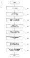
- FIG. 1 A perspective view of a heating cage, (b) a sectional view of the heating cage, and (c) a schematic sectional view showing a state in which the heating cage is filled with carbon fiber reinforced plastic. is there. It is a flowchart which shows an example of the manufacturing method of the reproduction
- a carbon fiber manufacturing method 1 (hereinafter simply referred to as “manufacturing method 1”) according to an embodiment of the present invention will be described with reference to FIGS. 1 to 3.
- a carbon fiber reinforced plastic 25 (hereinafter simply referred to as “CFRP 25”) as shown in FIG. It will be shown about what is performed using (hereinafter, simply referred to as a manufacturing apparatus 26).
- the manufacturing apparatus 26 includes a regeneration processing unit 3, a mesh belt 4, and a mesh transport unit 6.
- the regeneration processing unit 3 is constructed with a slender tunnel-shaped regeneration processing space 2 using refractory bricks, which are fire resistant materials.
- the mesh belt 4 is an endless belt arranged so as to penetrate the regeneration processing unit 3.
- the mesh transport unit 6 supports the mesh belt 4 and includes a plurality of rotating rollers 5 that can rotate around an axis.
- the regeneration processing space 2 is divided into three regions including a preheating unit 11, a heating removal unit 7, and a cooling unit 9.
- the heating removal unit 7 is installed in the heating area HZ in the center area.
- the cooling unit 9 is provided in the cooling zone CZ on the conveyance downstream side of the heating zone HZ, and gradually cools the produced regenerated carbon fiber 8 to near the room temperature.
- the preheating unit 11 is provided in the preheating area PZ on the upstream side of the conveyance of the heating area HZ, and preheats the CFRP 25 filled in the heating cage 10 to a predetermined heating temperature before reaching the heating area HZ. To do.
- the manufacturing apparatus 26 also includes a residual gas recovery unit 13 and a residual gas combustion unit 15. The residual gas recovery unit 13 is opened to a part of the regeneration processing unit 3 so as to communicate with the preheating region PZ, and reserve gas components 12 including smoke and hydrocarbon gas generated in the preheating region PZ are reserved.
- the residual gas combustion unit 15 brings the recovered residual gas component 12 close to the flame of the burner B, re-combusts it in the combustion furnace 14, and then releases it to the outside.
- the CFRP 25 in the heating cage 10 placed on the mesh belt 4 is transported along the transport direction (the direction of arrow A in FIG. 1), and is introduced into the regeneration processing unit 3 on the upstream side of the transport. Are introduced into the regeneration processing space 2 and further discharged out of the regeneration processing space 2 through a discharge port 17 opened on the downstream side of the conveyance.
- the regeneration processing space 2 between the introduction port 16 and the discharge port 17 three regions are set as described above. More specifically, for gradually heating the CFRP 25 in the heating cage 10 along a temperature gradient set in advance so as to reach a predetermined heating temperature (for example, 550 ° C.) from a temperature near room temperature.
- a predetermined heating temperature for example, 550 ° C.
- Preheated zone PZ and the heating temperature reached in the preheated zone PZ are set on the downstream side of the preheated zone PZ, and the heating temperature reached in the preheated zone PZ is kept as it is, and the CFRP 25 is heated to thermally decompose the matrix components to produce the regenerated carbon fiber 8 It is divided into three regions, namely, a heating region HZ for cooling and a cooling region CZ for cooling the regenerated carbon fiber 8 after the regeneration process to near the room temperature.
- the mesh transport unit 6 having the mesh belt 4 made of a net-like member has a configuration of the mesh belt 4 and a plurality of rotating rollers 5 as already shown.
- the mesh conveyance unit 6 has a known configuration such as a rotation driving motor that generates a rotational force for rotating the rotation roller 5 and a rotation transmission mechanism for transmitting the rotation force to the rotation roller 5.
- the details are omitted here.
- the heating removal unit 7 and the preheating unit 11 are interposed between an upper belt 18 positioned on the upper side of the annular mesh belt 4 and a lower belt 19 positioned on the lower side.
- the heating elements 21 are respectively arranged so as to face the inner surface 20.
- the heating element 21 generates resistance heat when current is supplied.
- the manufacturing apparatus 26 includes a current supply unit for supplying current to the heating element 21, a current adjustment mechanism that controls resistance heat generated by adjusting the supplied current value, and the preheating region PZ and the heating region HZ.
- a temperature measurement sensor an oxygen concentration sensor, a carbon monoxide concentration sensor, and the like that are installed at each of the plurality of locations and measure the temperature at the position, illustration is omitted here.
- the cooling unit 9 provided in the cooling zone CZ gradually cools the regenerated carbon fiber 8 produced by thermally decomposing the matrix component in the heating zone HZ.
- the recycled carbon fiber 8 is cooled to a temperature at which the worker can collect the carbon fiber 8 when it is discharged from the discharge port 17.
- an air supply unit 22 that forcibly supplies cold air (outside air) into the cooling region CZ from the vicinity of the discharge port 17 toward the upstream side of conveyance is provided.
- a plurality of communication ports 23 opened upward so as to communicate with the regeneration processing space 2 are opened, and the communication ports 23 and the intake duct 24 are connected.
- the forcedly supplied air is warmed by heat exchange by contacting the high-temperature regenerated carbon fiber 8 in the cooling zone CZ, and a part of the air (for example, about 60%) is connected to the communication port 23.
- the air is discharged to the outside of the manufacturing apparatus 26 through the intake duct 24, and the remaining air (for example, about 40%) flows to the heating region HZ on the upstream side of the conveyance.
- the heating cage 10 used in the manufacturing apparatus 26 is configured as a substantially rectangular parallelepiped casing as shown in FIG. More specifically, a cage bottom surface portion 27 made of a square plate having a side of 47 cm and a cage side surface portion 28 made of four rectangular plates having a height of 15 cm suspended from the respective edges of the cage bottom surface portion 27 are provided.
- the cage main body 29 is mainly composed of a square plate having a side of 50 cm, and a cage lid portion 30 placed so as to cover the cage main body 29 from above.
- the cage bottom surface portion 27 and the cage side surface portion 28 of the cage body 29 and the cage lid portion 30 are each made of a breathable material made of a mesh member.
- the bulk density of the CFRP 25 can be calculated from the weight of the CFRP 25 filled in the filling space 31 and the height from the bottom surface portion 27 of the cage.
- the CFRP 25 is filled evenly in the filling space 31, and the bulk density is calculated assuming that the height occupied in the filling space 31 is constant.
- the CFRP 25 to be subjected to the regeneration process in the manufacturing method 1 is a collection of scraps and the like (including prepregs before firing) extracted from the manufacturing process for manufacturing products using carbon fiber reinforced plastic. It assumes a sheet-like material. Since the collected scraps and the like contain paper and other contaminants, those that have been previously removed are used. Thereafter, the CFRP 25 is set in a carbonization furnace of a carbonization carbonization apparatus (not shown), and a low boiling point substance and a part of the matrix component contained in the CFRP 25 are carbonized (dry distillation process S1).
- the carbonization temperature by a carbonization carbonization apparatus is set to 550 degreeC, and this is continued for 8 hours.
- CFRP 25 is heated in an oxygen-free state in the carbonization furnace, a low-boiling substance is volatilized, and a hydrocarbon gas such as methane or benzene is generated.
- CFRP25 is carbonized.
- the carbon content of the carbonized CFRP 25 obtained by the carbonization step S1 is adjusted so as to be about 12%.
- superheated steam may be added to the carbonization furnace during carbonization to increase the effect of carbonization.
- the carbonized CFRP 25 obtained in the carbonization step S1 has a smaller volume than before the carbonization due to the generation of the hydrocarbon gas and the like, but still maintains the shape before the carbonization.
- the carbonized CFRP 25 is cut into a predetermined size in order to fill the filling space 31 of the heating cage 10 (cutting step S2). In this embodiment, it cuts into 50 mm length by using the existing cutting machine. Thereafter, the filled CFRP 25 is filled in the filling space 31.
- the heating cage 10 filled with the CFRP 25 is placed on the mesh belt 4 in the vicinity of the introduction port 16 (see FIG. 1).
- the heating elements 21 of the heating removal unit 7 and the preheating unit 11 of the manufacturing apparatus 26 are preliminarily heated and adjusted to have heating temperatures and temperature gradients set in the heating region HZ and the preheating region PZ. .
- the mesh transport unit 6 operates. Specifically, the mesh belt 4 is driven by the rotation of the rotating roller 5 that supports the mesh belt 4.
- the upper belt 18 located above the mesh belt 4 moves from the upstream end 4a on the upstream side of the conveyor belt toward the downstream end 4b on the downstream side.
- the moving direction is reversed at the downstream end 4b, and the lower belt 19 located on the lower side of the mesh belt 4 moves from the downstream side of the transport toward the upstream side of the transport.
- the heating cage 10 placed on the upper belt 18 of the mesh belt 4 moves in the horizontal direction (heating cage conveying step S4).
- the moving speed of the mesh belt 4, that is, the conveying speed of the heating cage 10 is set to 12.2 m / h ( ⁇ 0.20 m / min).
- the distance in the furnace from the inlet 16 to the outlet 17 of the regeneration processing unit 3 is set to 26.5 m, while the entire length from the upstream end 4a to the downstream end 4b. Is set to be 35.0 m.
- the heating cage 10 is conveyed through the regeneration processing space 2 over 130 minutes until it is introduced from the inlet 16 and discharged from the outlet 17.
- another heating cage 10 is placed in close proximity.
- the opening shape of the introduction port 16 and the cross-sectional shape of the heating cage 10 are substantially matched. Only a slight gap is formed between the opening edge of the inlet 16 and the cage surface 10 a of the heating cage 10. As a result, since only the minimum necessary amount of outside air or the like enters the regeneration processing space 2 from the inlet 16 side, the change in the temperature gradient in the preheating region PZ is hardly affected. In addition to this, by placing another heating cage 10 on the mesh belt 4 immediately after one heating cage 10, the amount of outside air flowing from the inlet port 16 is limited and at the same time, The heating cage 10 and the CFRP 25 having characteristics do not affect the temperature gradient in the preheating region PZ. As a result, stable heating up to the target heating temperature is possible.
- the heating cage 10 introduced into the preheating area PZ of the regeneration processing space 2 from the inlet 16 of the regeneration processing unit 3 is heated by heat generated from the heating element 21 of the preheating unit 11 (preheating step S5).
- a residual gas component 12 such as hydrocarbon gas or smoke may be generated from a part of the matrix component due to a substance not released in the dry distillation step S1.
- the residual gas component 12 is recovered by the residual gas recovery unit 13 connected above the preheating zone PZ, and is burned completely in the burner B while supplying sufficient oxygen to the recovered residual gas component 12. Carbon dioxide and water can be generated, and these can be released into the atmosphere with a reduced impact on the natural environment.
- the heating cage 10 and the CFRP 25 that have reached the heating zone HZ via the preheating zone PZ are heated in order to remove the remaining matrix component carbides by heating in the regeneration processing space 2 under an oxygen atmosphere (heating removal step S6).
- the heating temperature of the heating zone HZ is set to 550 ° C. in this embodiment.
- the carbon fiber itself of CFRP25 is not gasified in an oxygen atmosphere unless the heating temperature is 800 to 850 ° C. or higher. As a result, only the carbide derived from the matrix component is removed by heating by the oxidation reaction, and the regenerated carbon fiber 8 is produced.
- the regenerated carbon fiber 8 is moved to the cooling zone CZ while the carbide of the matrix component is not completely removed.
- the carbide (fixed carbon) of the matrix component adheres to the fiber surface of the regenerated carbon fiber 8.
- the residual carbon ratio of the fixed carbon is set to be around 3% by weight.
- the regenerated carbon fiber 8 that has reached the cooling zone CZ does not receive heat from the heating element 21 of the heating removal unit 7, it gradually releases heat while being conveyed along the mesh belt 4. It is cooled (cooling step S7). At this time, since the outside air is supplied from the downstream side of the conveyance by the air supply unit 22, the temperature of the regenerated carbon fiber 8 in contact with the outside air is further sharply lowered, and the cooling region CZ is set to be short. Even if it is a case, sufficient cooling effect can be acquired. Since the fixed carbon adheres to the regenerated carbon fiber 8, scattering by the outside air from the air supply section 22 is prevented as compared with the case where the matrix component is completely removed.
- the outside air sent to the cooling zone CZ is still in contact with the high-temperature regenerated carbon fiber 8 and is warmed by heat exchange. A part of the supplied outside air is sucked in the intake duct 24 and discharged to the outside of the manufacturing apparatus 26. On the other hand, a part of the remaining outside air reaches the heating zone HZ. This outside air contains oxygen and is consumed for the oxidation reaction for gasifying the carbide of the matrix component.
- the regenerated carbon fiber 8 reaches the end of the reclaim processing space 2, is sufficiently cooled, and is discharged from the discharge port 17 (step S8).
- the carbon fiber (regenerated carbon fiber 8) itself is not thermally decomposed at a heating temperature of about 550 ° C., the thickness or the like of the regenerated carbon fiber 8 in the heating cage 10 does not change. .
- the density is increased, and there is an advantage that the handleability is excellent compared to the case where the matrix component is completely removed. It should be noted that the presence of about 3% fixed carbon has no particular effect upon reuse.
- the raw material CFRP 25 is placed on the mesh belt on the upstream side of the conveyance and conveyed at a predetermined conveyance speed. It is decomposed by heating, leaving a part of it. By thermal decomposition, it is possible to selectively remove only the matrix component from the CFRP 25 and to produce the regenerated carbon fiber 8 that is not easily scattered by wind or the like. Furthermore, before the introduction into the regeneration processing space 2, the heating in the regeneration processing space 2 is stabilized by filling the heating cage 10 so as to have a specified bulk density. As a result, the residual rate of fixed carbon can be stabilized.
- the contact area between the CFRP 25 and oxygen (atmosphere) in the heat removal unit 7 can be adjusted by controlling the bulk density of the CFRP 25.
- the contact with oxygen at a high temperature increases the possibility of occurrence of problems such as loss due to gasification of the regenerated carbon fiber 8 or deterioration of mechanical properties of the regenerated carbon fiber 8. Therefore, the loss of the regenerated carbon fiber 8 and the like can be minimized by adjusting the contact area with oxygen.
- the tensile strength of the regenerated carbon fiber 8 of this embodiment was verified.
- the tensile test was performed by a simple tensile test method based on JIS R 7606.
- the regenerated carbon fiber 8 produced according to this example has less variation in strength than the unused virgin carbon fiber, and has an average strength of 80% with respect to the virgin carbon fiber. It became clear that this is possible.
- the carbonization process S1 was previously performed on the CFRP 25 to be regenerated, and the matrix component was carbonized to show a residual carbon ratio of about 12%. It is not limited, You may not implement such dry distillation process S1 as needed. That is, if the matrix component is gasified when the temperature is raised to the heating temperature in the preheating region PZ, the same effect as dry distillation can be obtained. Furthermore, although what cut
- the heating cage 10 is transported to the regeneration processing space 2 by using the mesh transport unit 6 having the mesh belt 4, but is not limited thereto. Any other roller hearth kiln may be used.
- the mesh belt 4 is used to improve heat propagation and perform efficient heating. Can do.
- the manufacturing method 1 of this embodiment although what cuts CFRP25 to 50 mm length was shown, it is not limited to this, It cuts to 3.5 mm-150 mm using a cutting machine, It doesn't matter. Thereby, it becomes possible to regenerate the regenerated carbon fiber 8 according to the reuse application.
- the cutting step S2 is not limited to one time.
- the cutting step S2 is performed twice or a plurality of times. You may do.
- CFRP containing an epoxy resin as a matrix component is exemplified, but the present invention is not limited to this.
- the resin used as the matrix component include a polypropylene resin, a polyethylene resin, a polymethyl methacrylate resin, a saturated polyester resin, and a polycarbonate resin as the thermoplastic resin in addition to the epoxy resin.
- a thermosetting resin unsaturated polyester resin, a phenol resin, vinyl ester resin etc. can be illustrated other than an epoxy resin.
- the case where the residual carbon ratio of the CFRP processed in the carbonization step S1 is adjusted to 12% by weight is exemplified.
- the residual carbon ratio is adjusted in consideration of the type of the matrix component, the content of the matrix component in the CFRP, the shape of the CFRP, and the energy efficiency of the entire manufacturing method.
- the residual carbon ratio of the CFRP processed in the carbonization step S1 is adjusted from about 10% by weight to about 12% by weight.
- the case where the residual carbon ratio of the regenerated carbon fiber is adjusted to 3% by weight is exemplified.
- the residual carbon ratio can be adjusted to 0.5 wt% or more and 11.0 wt% or less according to the intended use.
- Regenerated carbon fiber with a residual carbon ratio of 0.5% by weight or less may have insufficient mechanical strength due to a decrease in mechanical properties, and may not be in a fiber bundle state and may be scattered during production. .
- the regenerated carbon fiber having a residual carbon ratio of 11.5% by weight or more may not be flexible while maintaining the form of the fiber bundle.
Abstract
[Problem] To provide: an apparatus for manufacturing a regenerated carbon fiber having excellent handleability from a carbon fiber reinforced plastic (CFRP) as raw material; a process for manufacturing the regenerated carbon fiber; and a regenerated carbon fiber. [Solution] A carbon fiber manufacturing process (1) includes principally: a packing step (S3) for packing a heating cage (10) with a CFRP (25) in a prescribed bulk density; a heating cage conveying step (S5) for introducing the heating cage (10) into a regeneration treatment section (3) having a regeneration treatment space (2); a heating/removing step (S6) for heating the CFRP (25) in a heating/removing section provided in a heating zone and thereby removing the matrix components with a part thereof left as fixed carbon; and a cooling step (S7) for cooling the resulting regenerated carbon fiber (8) having fixed carbon adhering thereto. In the regenerated carbon fiber (8) manufactured by this manufacturing process with this manufacturing apparatus, the ratio of carbon remaining as fixed carbon is 0.5 to 11.0 wt%, said carbon being resulting from the matrix components of CFRP.
Description
本発明は、再生炭素繊維の製造装置と、再生炭素繊維の製造方法と、再生炭素繊維とに関するものである。特に、炭素繊維強化プラスチックを高温で加熱し、マトリックス成分を除去することで紙、不織布等の原料として再利用可能な再生炭素繊維を製造するための、再生炭素繊維の製造装置及び製造方法と、これらの技術により製造された再生炭素繊維に関するものである。
The present invention relates to a regenerated carbon fiber production apparatus, a regenerated carbon fiber production method, and a regenerated carbon fiber. In particular, a carbon fiber reinforced plastic is heated at a high temperature to remove recycle carbon fibers that can be reused as a raw material for paper, nonwoven fabric, etc. by removing the matrix component, The present invention relates to a regenerated carbon fiber produced by these techniques.
高強度及び高弾性率等の優れた力学的特性を備える材料として炭素繊維が知られている。この炭素繊維をフィラー成分として使用し、エポキシ樹脂やポリエステル樹脂等をマトリックス成分とした炭素繊維強化プラスチック(Carbon Fiber Reinforced Plastic、以下CFRPとも言う)が製造されている。炭素繊維は、航空・宇宙産業等を始めとする各種産業分野において広く用いられている。
Carbon fiber is known as a material having excellent mechanical properties such as high strength and high elastic modulus. Carbon fiber reinforced plastic (Carbon Fiber Reinforced Plastic, hereinafter also referred to as CFRP) is produced using this carbon fiber as a filler component and an epoxy resin or polyester resin as a matrix component. Carbon fiber is widely used in various industrial fields including aviation and space industries.
炭素繊維強化プラスチックは、主に、炭素繊維にマトリックス成分の樹脂を浸透させたプリプレグを生成し、このプリプレグをオートクレーブ内で加圧しながら焼成することにより製造されている。この炭素繊維強化プラスチックの製造工程では、製品以外に多くの端材が発生している。特に、航空機の機体等といった、大きなサイズの製品を製造する場合、上記端材が大量に発生する。このため、端材の処分が問題となることがあった。前述のように、炭素繊維強化プラスチックは、異なる性状のフィラー成分及びマトリックス成分が混在したものであり、これらをそれぞれ分離して再利用(リサイクル)若しくは再使用(リユース)することは技術的な困難性が高かった。またコストやエネルギー効率の点から有効ではなかった。その結果、現状では、製造時に発生した端材、及び未使用のプリプレグの大部分が、埋立てや焼却等によって処分されることが多かった。さらに、製品としての機能を終えた後に回収された炭素繊維強化プラスチックも同様に、埋立て等によって処分されていた。
Carbon fiber reinforced plastic is mainly produced by producing a prepreg in which a matrix component resin is infiltrated into carbon fiber, and firing this prepreg while pressing it in an autoclave. In the manufacturing process of this carbon fiber reinforced plastic, many end materials are generated in addition to the product. In particular, when manufacturing a large-sized product such as an aircraft body, a large amount of the above-mentioned scrap material is generated. For this reason, disposal of the mill ends sometimes becomes a problem. As described above, carbon fiber reinforced plastics are a mixture of filler components and matrix components having different properties, and it is technically difficult to separate them for reuse (recycling) or reuse (reuse). The nature was high. Also, it was not effective in terms of cost and energy efficiency. As a result, at present, most of the scraps generated during production and unused prepregs are often disposed of by landfill or incineration. Furthermore, the carbon fiber reinforced plastic collected after the function as a product was also disposed of by landfill or the like.
本願発明の発明者等によって、炭素繊維強化プラスチックからマトリックス成分のみを熱分解によって加熱除去し、力学的特性を低下させることなしに炭素繊維を選択的に回収する、炭素繊維の再生処理装置及び再生処理方法(特許文献1及び特許文献2参照)に関する技術が既に開発されている。これによると、再生処理部は、耐火性素材によって細長トンネル形状の再生処理空間が構築されている。この再生処理部の中にはメッシュ状のベルトコンベアが配設されている。係るベルトコンベアを利用して炭素繊維強化プラスチックを再生処理空間に連続的に供給するとともに、再生処理空間内の加熱領域で炭素繊維強化プラスチックを加熱することにより、熱可塑性のエポキシ樹脂等のマトリックス成分のみを熱分解によってガス化し、炭素繊維(再生炭素繊維)を長繊維状の状態で回収することが可能となる。その結果、大量の炭素繊維強化プラスチックを効率的に熱分解することができ、再生炭素繊維を生成することができる。
By the inventors of the present invention, only the matrix components are removed from the carbon fiber reinforced plastic by thermal decomposition, and the carbon fibers are selectively recovered without deteriorating the mechanical properties. Techniques relating to processing methods (see Patent Document 1 and Patent Document 2) have already been developed. According to this, in the regeneration processing unit, a slender tunnel-shaped regeneration processing space is constructed of a fireproof material. A mesh belt conveyor is disposed in the regeneration processing unit. By continuously supplying carbon fiber reinforced plastic to the regeneration processing space using such a belt conveyor and heating the carbon fiber reinforced plastic in the heating region in the regeneration processing space, matrix components such as thermoplastic epoxy resin Only the gas can be gasified by pyrolysis, and the carbon fiber (regenerated carbon fiber) can be recovered in a long fiber state. As a result, a large amount of carbon fiber reinforced plastic can be efficiently pyrolyzed, and regenerated carbon fiber can be produced.
又、特許文献3には、炭素繊維強化プラスチックを800℃以上の過熱水蒸気によって処理することにより、プラスチックの68~80%を除去した状態で炭素繊維を回収する技術が開示されている。特許文献3には、過熱水蒸気を製造するヒータ部と、製造された水蒸気を導入する導入部と、炭素繊維強化プラスチックを保持する保持部を備えた回収装置が開示されている。
Patent Document 3 discloses a technique for recovering carbon fiber in a state where 68 to 80% of the plastic is removed by treating the carbon fiber reinforced plastic with superheated steam at 800 ° C. or higher. Patent Document 3 discloses a recovery device that includes a heater section that produces superheated steam, an introduction section that introduces the produced steam, and a holding section that holds carbon fiber reinforced plastic.
しかしながら、特許文献1及び特許文献2に記載の炭素繊維の再生処理装置及び再生処理方法は、下記に掲げる課題があった。すなわち、回収された炭素繊維強化プラスチックの端材等は、製品の使用部位等によって種々の形状をしている。このため、形状の差異により熱分解の際の熱の伝達に違いが生じ、加熱条件にバラツキが生じることがあった。その結果、連続炉を有する再生処理装置を用いて炭素繊維強化プラスチックから再生炭素繊維を生成する揚合、上記熱的特性の違いにより、一部が再生処理空間で過熱状態となって燃焼したり、或いは熱が十分に伝達されずマトリックス成分の一部が残る等の不具合を生じ、得られた再生炭素繊維の性状及び品質に偏りが生じることがあった。特に、炭素繊維強化プラスチックの充填密度(嵩密度)の違いによる再生処理空間との接触面積の大きさによって、熱の伝達に違いが生じ、上述の不具合が発生しやすかった。
However, the carbon fiber regeneration treatment apparatus and the regeneration treatment method described in Patent Document 1 and Patent Document 2 have the following problems. That is, the collected carbon fiber reinforced plastic end material has various shapes depending on the use part of the product. For this reason, a difference in shape causes a difference in heat transfer during pyrolysis, which may cause variations in heating conditions. As a result, regenerative carbon fiber is produced from carbon fiber reinforced plastic using a regenerative processing apparatus having a continuous furnace, and due to the difference in thermal characteristics, some of the regenerated processing space burns in an overheated state. Or, heat may not be sufficiently transferred, causing a problem such as a part of the matrix component remaining, and the properties and quality of the obtained regenerated carbon fiber may be biased. In particular, the heat transfer differs depending on the size of the contact area with the regeneration processing space due to the difference in the packing density (bulk density) of the carbon fiber reinforced plastic, and the above-mentioned problems are likely to occur.
加えて、従来の炭素繊維の再生処理方法は、炭素繊維強化プラスチック中に含まれるマトリックス成分を熱分解によって完全に除去し、マトリックス成分の残存率が0%の状態の再生炭素繊維を生成することを目的としていた。再生処理空間の加熱領域では、必要以上の加熱温度及び/または加熱時間で炭素繊維強化プラスチックを処理するため、回収された再生炭素繊維の力学的特性が低下するおそれがあった。その結果、再使用及び再利用する際の用途が限定されることがあった。また、マトリックス成分が完全に除去された再生炭素繊維は、綿毛のような態様を示し、かつ密度も小さいため、僅かな風によっても容易に飛散する可能性があった。そのため、従来の再生処理装置を用いて再生炭素繊維を製造する場合、再生処理空間の加熱領域及び冷却領域で飛散しないように慎重な取扱いが必要となった。また、回収後に再使用等をする場合であっても再生炭素繊維の取扱い性(ハンドリング性)が問題となることがあった。
In addition, the conventional carbon fiber regeneration treatment method completely removes the matrix component contained in the carbon fiber reinforced plastic by pyrolysis, and produces a regenerated carbon fiber in which the residual rate of the matrix component is 0%. Was aimed at. In the heating region of the regeneration processing space, the carbon fiber reinforced plastic is processed at a heating temperature and / or heating time that is more than necessary, so that the mechanical properties of the recovered recycled carbon fiber may be deteriorated. As a result, the use at the time of reuse and reuse may be limited. In addition, the regenerated carbon fiber from which the matrix component has been completely removed has a fluff-like aspect and has a small density, and thus may be easily scattered even by a slight wind. For this reason, when producing regenerated carbon fiber using a conventional reclaim processing apparatus, it is necessary to handle it carefully so as not to be scattered in the heating region and the cooling region of the regeneration processing space. In addition, even when reused after collection, the handleability (handling property) of the regenerated carbon fiber may be a problem.
一方、特許文献3に開示される炭素繊維の回収方法においては、マトリックス成分の20~32%が残存するため、回収された炭素繊維は繊維束の形態を保っている一方で、柔軟性に欠ける可能性がある。このため、回収された炭素繊維を不織布等に再利用する場合には、更なる加工が必要となる可能性が高い。
On the other hand, in the carbon fiber recovery method disclosed in Patent Document 3, since 20 to 32% of the matrix component remains, the recovered carbon fiber maintains the form of the fiber bundle, but lacks flexibility. there is a possibility. For this reason, when the recovered carbon fibers are reused in a nonwoven fabric or the like, there is a high possibility that further processing is required.
本発明は、上記実情に鑑み、炭素繊維強化プラスチックを安定した加熱条件で加工することにより、再生炭素繊維を効率的に、且つ低いコストで製造する技術を提供することを目的としている。即ち本発明は、加工に適した再生炭素繊維と、この再生炭素繊維の製造装置及び製造方法の提供を課題とするものである。
In view of the above circumstances, an object of the present invention is to provide a technique for manufacturing a regenerated carbon fiber efficiently and at a low cost by processing a carbon fiber reinforced plastic under a stable heating condition. That is, an object of the present invention is to provide a regenerated carbon fiber suitable for processing, a production apparatus and a production method for the regenerated carbon fiber.
上記の課題を解決するために、本発明の炭素繊維の製造方法は、嵩密度充填工程と、加熱ケージ搬送工程と、加熱除去工程と、冷却工程と、を備えている。嵩密度充填工程は、炭素繊維及びマトリックス成分を含有する炭素繊維強化プラスチックを通気性材料で各面が形成された筐体状の加熱ケージの中に予め規定された嵩密度となるように充填する。加熱ケージ搬送工程は、耐火性素材によって内部に細長トンネル形状の再生処理空間が構築されており、再生処理空間に連通する導入口及び排出口がそれぞれ開口した再生処理部に、炭素繊維強化プラスチックの充填された加熱ケージを搬送する。加熱除去工程は、再生処理空間の加熱領域に設けられた加熱除去部によって、搬送される加熱ケージ内の炭素繊維強化プラスチックを加熱し、マトリックス成分を除去する。冷却工程は、再生処理空間の加熱領域の搬送下流側の冷却領域に設けられた冷却部によって、マトリックス成分の加熱除去された再生炭素繊維を搬送しながら冷却する。
In order to solve the above-described problems, the carbon fiber manufacturing method of the present invention includes a bulk density filling step, a heating cage conveyance step, a heating removal step, and a cooling step. In the bulk density filling step, carbon fiber reinforced plastic containing carbon fibers and a matrix component is filled into a casing-shaped heating cage having each surface formed of a breathable material so as to have a predetermined bulk density. . In the heating cage transport process, a slender tunnel-shaped reclaim processing space is built inside with a fireproof material, and a carbon fiber reinforced plastic is placed in the reclaim processing section where the introduction port and discharge port communicating with the reclaim processing space are opened. Transport the filled heating cage. In the heat removal step, the carbon fiber reinforced plastic in the heating cage being conveyed is heated by a heat removal unit provided in the heating region of the regeneration processing space to remove the matrix component. In the cooling step, the regenerated carbon fiber from which the matrix component has been removed by heating is cooled while being conveyed by a cooling unit provided in the cooling area on the downstream side of the heating area of the regeneration processing space.
ここで、加熱ケージとは、網状(或いは孔状)等の通気性材料によって、各ケージ面が形成された略直方体形状の筐体であり、ケージ内部の充填空間に加熱対象の炭素繊維強化プラスチックを充填可能なものである。加熱ケージが通気性材料によって形成されているため、炭素繊維強化プラスチックに加熱時の熱を効率的に伝達することが可能となり、さらにケージ内部でマトリックス成分が熱分解して発生した分解ガスを加熱ケージの外に速やかに排出する機能を有している。なお、加熱ケージは、ステンレス等の金属材料を用いて構成される。さらに、筐体上部に網状等の通気性材料からなる蓋等を設け、充填完了後に炭素繊維強化プラスチックをケージ内部に閉塞することが可能となる。ここで、本発明における「嵩密度」とは、加熱ケージの充填空間に充填した炭素繊維強化プラスチックの内容積を体積とし、炭素繊維強化プラスチックの重量で割ったものとして定義する。このとき、炭素繊維強化プラスチックの内容積には、炭素繊維強化プラスチック同士の間隙の体積、炭素繊維強化プラスチックの表面の凹凸の空間の体積、及び炭素繊維強化プラスチックと加熱ケージの間隙の体積が含まれている。なお、加熱ケージに充填された炭素繊維強化プラスチックの内容積を正確に求めることは困難であるため、本発明では、加熱ケージのケージ底面の面積にケージ底面からの充填高さを掛けることにより、炭素繊維強化プラスチックの内容積を算出している。すなわち、嵩密度=充填した炭素繊維強化プラスチックの重量/(ケージ底面の底面積×充填高さ)としている。
Here, the heating cage is a substantially rectangular parallelepiped housing in which each cage surface is formed of a breathable material such as a net (or hole), and the carbon fiber reinforced plastic to be heated in the filling space inside the cage. Can be filled. Since the heating cage is made of a breathable material, heat during heating can be efficiently transferred to the carbon fiber reinforced plastic, and further, the decomposition gas generated by the thermal decomposition of the matrix components inside the cage is heated. It has the function of quickly discharging out of the cage. The heating cage is configured using a metal material such as stainless steel. Further, a lid made of a breathable material such as a net is provided on the upper part of the housing, and the carbon fiber reinforced plastic can be closed inside the cage after filling is completed. Here, “bulk density” in the present invention is defined as a volume obtained by dividing the internal volume of the carbon fiber reinforced plastic filled in the filling space of the heating cage by the weight of the carbon fiber reinforced plastic. At this time, the internal volume of the carbon fiber reinforced plastic includes the volume of the gap between the carbon fiber reinforced plastics, the volume of the uneven surface of the carbon fiber reinforced plastic, and the volume of the gap between the carbon fiber reinforced plastic and the heating cage. It is. In addition, since it is difficult to accurately determine the inner volume of the carbon fiber reinforced plastic filled in the heating cage, in the present invention, the area of the bottom surface of the heating cage is multiplied by the filling height from the bottom surface of the cage. The internal volume of the carbon fiber reinforced plastic is calculated. That is, bulk density = weight of filled carbon fiber reinforced plastic / (bottom area of cage bottom surface × filling height).
一方、再生処理部とは、例えば、煉瓦のような耐火性素材を用いて、内部に細長トンネル形状の再生処理空間が構築されたものであり、再生処理空間の加熱領域で炭素繊維強化プラスチックを加熱して、再生炭素繊維を製造することが可能なものである。このとき、再生処理空間への加熱ケージの搬送は、複数のローラを並設した所謂「ローラハースキルン」等の搬送部や、或いはメッシュベルトを回転駆動させるメッシュ搬送部等を採用することが可能である。
On the other hand, the regeneration processing part is a structure in which a slender tunnel-shaped regeneration processing space is constructed inside using a fireproof material such as brick, and carbon fiber reinforced plastic is used in the heating region of the regeneration processing space. It is possible to produce regenerated carbon fiber by heating. At this time, the conveyance of the heating cage to the regeneration processing space can employ a conveyance unit such as a so-called “roller hearth kiln” in which a plurality of rollers are arranged in parallel, or a mesh conveyance unit that rotationally drives the mesh belt. It is.
また、加熱除去部とは、再生処理空間に加熱ケージに充填された状態で搬送された炭素繊維強化プラスチックを加熱し、マトリックス成分を熱分解させるためのものであり、加熱領域に設置された発熱体等によって主に構成されている。ここで、本発明の再生炭素繊維の製造方法において、処理対象となる炭素繊維強化プラスチックは、例えば、フィラー成分としてポリアクリロニトリル系炭素繊維(PAN系炭素繊維)を用い、マトリックス成分としてエポキシ樹脂等を用いたものを想定することができる。この場合、炭素繊維強化プラスチックに占めるマトリックス成分の重量比は、一般に約60重量%程度である。ここで、フィラー成分の炭素繊維の加熱分解温度が、例えば850℃前後であるのに対し、マトリックス成分のエポキシ樹脂等はそれよりも低い温度(例えば、400℃~600℃前後)でも熱分解し、ガス化する性質を備えている。そのため、徐々に再生処理空間の加熱領域(例えば、加熱温度=500℃に設定されている)に到達した炭素繊維強化プラスチックは、その到達の過程で含有するマトリックス成分のみが固体から気化し、炭素繊維のみが再生処理部の排出口から排出され、再生炭素繊維を製造することが可能となる。
The heat removal part is for heating the carbon fiber reinforced plastic conveyed in a state where the heating cage is filled in the regeneration processing space and thermally decomposing the matrix component. It is mainly composed by the body. Here, in the method for producing a regenerated carbon fiber of the present invention, the carbon fiber reinforced plastic to be treated uses, for example, a polyacrylonitrile-based carbon fiber (PAN-based carbon fiber) as a filler component, and an epoxy resin or the like as a matrix component. The one used can be assumed. In this case, the weight ratio of the matrix component in the carbon fiber reinforced plastic is generally about 60% by weight. Here, the thermal decomposition temperature of the carbon fiber of the filler component is, for example, around 850 ° C., whereas the epoxy resin of the matrix component is thermally decomposed even at a lower temperature (eg, around 400 ° C. to 600 ° C.). It has the property of gasifying. Therefore, the carbon fiber reinforced plastic that has gradually reached the heating region of the regeneration processing space (for example, the heating temperature is set to 500 ° C.), only the matrix component contained in the reaching process is vaporized from the solid, and carbon Only the fiber is discharged from the discharge port of the regeneration processing section, and it becomes possible to produce the regenerated carbon fiber.
したがって、本発明の再生炭素繊維の製造方法によれば、再生処理空間の加熱領域に導入する炭素繊維の嵩密度を、規定サイズの加熱ケージに充填することで一定にすることが可能となる。これにより、炭素繊維の加熱条件を安定させることが可能となり、マトリックス成分の加熱除去を再生処理空間で偏りなく行うことができる。
Therefore, according to the method for producing a regenerated carbon fiber of the present invention, the bulk density of the carbon fiber introduced into the heating region of the regeneration processing space can be made constant by filling a heating cage of a prescribed size. Thereby, it becomes possible to stabilize the heating conditions of the carbon fiber, and the heating and removal of the matrix component can be carried out evenly in the regeneration processing space.
さらに、本発明の再生炭素繊維の製造方法の加熱除去工程は、炭素繊維強化プラスチックのマトリックス成分の一部を加熱によって固定炭素に転換し、この固定炭素が繊維表面に付着した再生炭素繊維を製造する工程とすることができる。
Further, in the heat removal step of the method for producing regenerated carbon fiber of the present invention, a part of the matrix component of the carbon fiber reinforced plastic is converted to fixed carbon by heating, and the regenerated carbon fiber having the fixed carbon attached to the fiber surface is produced. It can be set as the process to do.
したがって、本発明の再生炭素繊維の製造方法は、加熱除去工程によって、炭素繊維のマトリックス成分を繊維表面から完全に除去するものではなく、マトリックス成分の一部を固定炭素に転換することが行われてもよい。ここで、固定炭素とは、マトリックス成分が加熱によりガス化し、二酸化炭素等に分解する際、その一部が灰化し粉体等の態様で残存したものである。この固定炭素が炭素繊維の繊維表面に付着することにより、それぞれの再生炭素繊維同士の絡まり(凝集)の程度が高くなり、束のような塊になりやすい。そのため、風等によっても容易に飛散する可能性が抑えられ、取扱い性が良好となる。なお、固定炭素の残存炭素率が高くなると、再生炭素繊維同士を密着させる一種のバインダとして機能し、塊の程度がより大きくなることもある。
Therefore, in the method for producing regenerated carbon fiber of the present invention, the matrix component of the carbon fiber is not completely removed from the fiber surface by the heat removal step, but a part of the matrix component is converted to fixed carbon. May be. Here, the fixed carbon is one in which, when the matrix component is gasified by heating and decomposes into carbon dioxide or the like, a part thereof is ashed and remains in the form of powder or the like. When this fixed carbon adheres to the fiber surface of the carbon fiber, the degree of entanglement (aggregation) between the respective regenerated carbon fibers increases, and it tends to be a lump like a bundle. Therefore, the possibility of being easily scattered by wind or the like is suppressed, and the handleability is improved. In addition, when the residual carbon rate of fixed carbon becomes high, it will function as a kind of binder which adhere | attaches regenerated carbon fiber, and the grade of a lump may become larger.
さらに、本発明の再生炭素繊維の製造方法の加熱除去工程は、固定炭素の残存炭素率を、炭素繊維強化プラスチックに含まれているマトリックス成分の当初重量に対して、0.5重量%以上、11.0重量%以下とするように、前記マトリックス成分の加熱除去を行うことが好ましい。
Furthermore, the heat removal step of the method for producing a regenerated carbon fiber of the present invention, the residual carbon ratio of the fixed carbon is 0.5 wt% or more based on the initial weight of the matrix component contained in the carbon fiber reinforced plastic, The matrix component is preferably removed by heating so that the content is 11.0% by weight or less.
本発明の再生炭素繊維の製造方法によれば、固定炭素の残存炭素率が0.5重量%以上、11.0重量%以下に調整される。0.5重量%よりも固定炭素の残存炭素率が低い場合には、上述した取扱い性の向上が認められにくく、一方、11.0重量%を超える残存炭素率は、再生炭素繊維の繊維としての特性を損なうこととなり、再使用等に適さなくなる。そのため、0.5重量%以上、11.0重量%以下、さらに好ましくは、1.0重量%以上、5.0重量%以下に調整するものが特に好適である。
According to the method for producing regenerated carbon fiber of the present invention, the residual carbon ratio of fixed carbon is adjusted to 0.5 wt% or more and 11.0 wt% or less. When the residual carbon ratio of the fixed carbon is lower than 0.5% by weight, the above-described improvement in handleability is difficult to be recognized, while the residual carbon ratio exceeding 11.0% by weight is a regenerated carbon fiber fiber. This will impair the properties of the product, making it unsuitable for reuse. Therefore, it is particularly preferable to adjust the content to 0.5 wt% or more and 11.0 wt% or less, more preferably 1.0 wt% or more and 5.0 wt% or less.
さらに、本発明の再生炭素繊維の製造方法は、上記構成に加えて、嵩密度充填工程の前に実施される裁断工程を備えていてもよい。裁断工程は、炭素繊維強化プラスチックを予め規定されたサイズに裁断加工する工程である。
Furthermore, in addition to the above configuration, the method for producing a regenerated carbon fiber of the present invention may include a cutting step that is performed before the bulk density filling step. The cutting step is a step of cutting the carbon fiber reinforced plastic into a predetermined size.
予め炭素繊維強化プラスチックを所定の裁断サイズにカットすることで、嵩密度充填工程において、加熱ケージに炭素繊維強化プラスチックを充填する際の嵩密度の調整が行いやすくなる。ここで、嵩密度は特に限定されないものの、例えば、0.02グラム/立方センチメートル~0.15グラム/立方センチメートルの間に設定するものであってもよい。係る嵩密度の範囲に設定することで、炭素繊維強化プラスチックの聞に適度な空隙が形成され、加熱領域における熱の伝搬及び発生した分解ガスの流れも良好なものとなる。これにより、加熱条件が安定し、より効率的にマトリックス成分の熱分解処理が可能となる。なお、炭素繊維強化プラスチックを裁断するための裁断機(破砕機)が使用される。
By previously cutting the carbon fiber reinforced plastic into a predetermined cutting size, it becomes easy to adjust the bulk density when filling the heating cage with the carbon fiber reinforced plastic in the bulk density filling step. Here, the bulk density is not particularly limited, but may be set between 0.02 grams / cubic centimeter and 0.15 grams / cubic centimeter, for example. By setting the volume density within such a range, an appropriate void is formed in the carbon fiber reinforced plastic, and heat propagation in the heating region and the flow of the generated decomposition gas are also improved. Thereby, the heating conditions are stabilized, and the thermal decomposition treatment of the matrix component can be performed more efficiently. A cutting machine (crusher) for cutting the carbon fiber reinforced plastic is used.
さらに、本発明の再生炭素繊維の製造方法は、上記構成に加えて、乾留工程を備えていてもよい。乾留工程は、嵩密度充填工程の前に実施される工程であって、炭素繊維強化プラスチックを予め乾留し、マトリックス成分を炭化する工程である。乾留工程を備えることによって、加熱ケージには、予め乾留処理が行われた炭化済みの炭素繊維強化プラスチックが充填されることとなる。
Furthermore, the method for producing regenerated carbon fiber of the present invention may include a dry distillation step in addition to the above-described configuration. The carbonization step is a step performed before the bulk density filling step, and is a step of carbonizing the carbon fiber reinforced plastic in advance and carbonizing the matrix component. By providing the carbonization step, the heating cage is filled with carbonized carbon fiber reinforced plastic that has been previously carbonized.
ここで、乾留工程とは、例えば、400℃以上の加熱温度に設定されたバッチ式の加熱炉内に炭素繊維強化プラスチックを投入し、無酸素状態で加熱(所謂「蒸し焼き」)するものである。炭素繊維強化プラスチックに含まれる低沸点の物質及び水分等は、加熱により、ガス化及び炭化する。乾留工程により、引き続き行われる製造工程において、炭素繊維強化プラスチックに含まれるマトリックス成分の加熱除去時間を短縮化することが可能となる。さらに、乾留工程によって、予め炭素繊維強化プラスチックの炭化分を一定にすることができるために、加熱条件を安定させて、製造工程全体としてのエネルギー効率を良好なものとすることができる。なお、上述した裁断工程は、乾留後の炭素繊維強化プラスチックに対して実施してもよい。
Here, the carbonization process is, for example, putting carbon fiber reinforced plastic into a batch-type heating furnace set to a heating temperature of 400 ° C. or higher and heating it in an oxygen-free state (so-called “steaming”). . Low boiling point substances and moisture contained in the carbon fiber reinforced plastic are gasified and carbonized by heating. By the carbonization process, it is possible to shorten the heat removal time of the matrix component contained in the carbon fiber reinforced plastic in the subsequent manufacturing process. Furthermore, since carbonization of the carbon fiber reinforced plastic can be made constant in advance by the carbonization process, the heating conditions can be stabilized and the energy efficiency of the entire manufacturing process can be improved. In addition, you may implement the cutting process mentioned above with respect to the carbon fiber reinforced plastics after dry distillation.
本発明はまた、炭素繊維及びマトリックス成分を含有する炭素繊維強化プラスチックを原料として再生炭素繊維を製造する装置を提供する。本発明の製造装置は、加熱ケージと、再生処理部とを備えている。加熱ケージは、通気性材料で各面が形成されており、前記炭素繊維強化プラスチックを予め規定された嵩密度となるように充填する筐体状のケージである。再生処理部は、加熱ケージを搬送するメッシュ搬送部と、細長トンネル形状の加熱処理空間とを備えている。再生処理部は、炭素繊維強化プラスチックを連続的に加熱して前記マトリックス成分の一部を除去する。
The present invention also provides an apparatus for producing regenerated carbon fiber using carbon fiber reinforced plastic containing carbon fiber and a matrix component as a raw material. The manufacturing apparatus of the present invention includes a heating cage and a regeneration processing unit. Each surface of the heating cage is formed of a breathable material, and the heating cage is a housing-like cage filled with the carbon fiber reinforced plastic so as to have a predetermined bulk density. The regeneration processing unit includes a mesh transport unit that transports the heating cage and a heat treatment space having an elongated tunnel shape. The regeneration processing unit continuously heats the carbon fiber reinforced plastic to remove a part of the matrix component.
本発明はさらに、炭素繊維及びマトリックス成分を含有する炭素繊維強化プラスチックから製造される再生炭素繊維を提供する。本発明の再生炭素繊維は、原料の炭素繊維強化プラスチックに含まれていたマトリックス成分の一部が固定炭素に転換して表面に残存している。本発明の再生炭素繊維は、固定炭素の残存炭素率が、炭素繊維強化プラスチックのマトリックス成分の当初重量に対して0.5重量%以上、11.0重量%以下であることを特徴とする。
The present invention further provides a regenerated carbon fiber produced from a carbon fiber reinforced plastic containing carbon fiber and a matrix component. In the regenerated carbon fiber of the present invention, a part of the matrix component contained in the raw material carbon fiber reinforced plastic is converted to fixed carbon and remains on the surface. The regenerated carbon fiber of the present invention is characterized in that the residual carbon ratio of the fixed carbon is 0.5% by weight or more and 11.0% by weight or less based on the initial weight of the matrix component of the carbon fiber reinforced plastic.
本発明の効果として、炭素繊維強化プラスチックを加熱ケージに充填し、嵩密度を一定に調整した状態で再生処理部に導入し、再生炭素繊維を製造することができる。これにより、加熱領域における熱的特性を均一化し、安定した加熱条件で再生炭素繊維の製造を行うことができる。また、マトリックス成分の一部を固定炭素として残存させることにより、再生炭素繊維の取り扱い性を良好にすることができる。このとき、炭素繊維強化プラスチックの嵩密度を一定とすることにより、上記固定炭素の残存炭素率の調整を容易に行うことができる。
As an effect of the present invention, a carbon fiber reinforced plastic can be filled in a heating cage and introduced into a regeneration processing section in a state in which the bulk density is adjusted to be constant, whereby a regenerated carbon fiber can be produced. Thereby, the thermal characteristics in the heating region can be made uniform, and the regenerated carbon fiber can be produced under stable heating conditions. Moreover, the handleability of the regenerated carbon fiber can be improved by leaving a part of the matrix component as fixed carbon. At this time, by adjusting the bulk density of the carbon fiber reinforced plastic, the residual carbon ratio of the fixed carbon can be easily adjusted.
本発明の再生炭素繊維は、固定炭素の残存炭素率が0.5重量%以上、11.0重量%以下であることによって、力学的特性を維持し、飛散しにくいという優れた特性を有している。この結果、ハンドリング性が良く、特段の追加加工をすることなく通常の不織布製造装置や製紙装置で扱うことができる。
The regenerated carbon fiber of the present invention has excellent characteristics such that the residual carbon ratio of the fixed carbon is not less than 0.5% by weight and not more than 11.0% by weight, maintaining mechanical properties and being difficult to scatter. ing. As a result, it is easy to handle and can be handled by a normal nonwoven fabric manufacturing apparatus or papermaking apparatus without any special additional processing.
以下、本発明の一実施形態である炭素繊維の製造方法1(以下、単に「製造方法1」と称す)について、図1乃至図3に基づいて説明する。ここで、本実施形態の製造方法1は、図1に示すような炭素繊維強化プラスチック25(以下、単に「CFRP25」と称す)を連続的に加熱することが可能な再生炭素繊維の製造装置26(以下、単に製造装置26と称す)を用いて行うものについて示すものとする。
Hereinafter, a carbon fiber manufacturing method 1 (hereinafter simply referred to as “manufacturing method 1”) according to an embodiment of the present invention will be described with reference to FIGS. 1 to 3. Here, in the manufacturing method 1 of the present embodiment, a carbon fiber reinforced plastic 25 (hereinafter simply referred to as “CFRP 25”) as shown in FIG. It will be shown about what is performed using (hereinafter, simply referred to as a manufacturing apparatus 26).
ここで、製造装置26について説明する。製造装置26は、再生処理部3と、メッシュベルト4と、メッシュ搬送部6を備えている。再生処理部3は、耐火性素材である耐火煉瓦を用いて、内部に細長トンネル形状の再生処理空間2が構築されている。メッシュベルト4は、再生処理部3を貫通するように配置された無端状のベルトである。メッシュ搬送部6は、メッシュベルト4を支持しており、軸周りに回転可能な複数の回転ローラ5を有する。再生処理空間2は、予備加熱部11と、加熱除去部7と、冷却部9と、からなる三つの領域に分割されている。加熱除去部7は、中央の領域の加熱領域HZに設置されている。冷却部9は、加熱領域HZの搬送下流側の冷却領域CZに設けられており、製造された再生炭素繊維8を室温近傍まで徐冷する。予備加熱部11は、加熱領域HZの搬送上流側の予備加熱領域PZに設けられており、加熱領域HZに到達するまでに加熱ケージ10に充填されたCFRP25を所定の加熱温度まで予備的に加熱する。製造装置26はまた、残ガス回収部13と残ガス燃焼部15とを備えている。残ガス回収部13は、予備加熱領域PZに連通するように再生処理部3の一部に開口しており、予備加熱領域PZで発生した煙や炭化水素ガス等を含む残ガス成分12を予備加熱領域PZから吸引し、回収する。残ガス燃焼部15は、回収された残ガス成分12をバーナーBの炎に近接させ、燃焼炉14内で再燃焼させた後に外部に放出する。係る構成によって、メッシュベルト4に載置された加熱ケージ10内のCFRP25は、搬送方向(図1における矢印A方向)に沿って搬送され、搬送上流側の再生処理部3に開口した導入口16から再生処理空間2に導入され、さらに搬送下流側に開口した排出口17から再生処理空間2の外に排出される。
Here, the manufacturing apparatus 26 will be described. The manufacturing apparatus 26 includes a regeneration processing unit 3, a mesh belt 4, and a mesh transport unit 6. The regeneration processing unit 3 is constructed with a slender tunnel-shaped regeneration processing space 2 using refractory bricks, which are fire resistant materials. The mesh belt 4 is an endless belt arranged so as to penetrate the regeneration processing unit 3. The mesh transport unit 6 supports the mesh belt 4 and includes a plurality of rotating rollers 5 that can rotate around an axis. The regeneration processing space 2 is divided into three regions including a preheating unit 11, a heating removal unit 7, and a cooling unit 9. The heating removal unit 7 is installed in the heating area HZ in the center area. The cooling unit 9 is provided in the cooling zone CZ on the conveyance downstream side of the heating zone HZ, and gradually cools the produced regenerated carbon fiber 8 to near the room temperature. The preheating unit 11 is provided in the preheating area PZ on the upstream side of the conveyance of the heating area HZ, and preheats the CFRP 25 filled in the heating cage 10 to a predetermined heating temperature before reaching the heating area HZ. To do. The manufacturing apparatus 26 also includes a residual gas recovery unit 13 and a residual gas combustion unit 15. The residual gas recovery unit 13 is opened to a part of the regeneration processing unit 3 so as to communicate with the preheating region PZ, and reserve gas components 12 including smoke and hydrocarbon gas generated in the preheating region PZ are reserved. Suction and recovery from the heating zone PZ. The residual gas combustion unit 15 brings the recovered residual gas component 12 close to the flame of the burner B, re-combusts it in the combustion furnace 14, and then releases it to the outside. With this configuration, the CFRP 25 in the heating cage 10 placed on the mesh belt 4 is transported along the transport direction (the direction of arrow A in FIG. 1), and is introduced into the regeneration processing unit 3 on the upstream side of the transport. Are introduced into the regeneration processing space 2 and further discharged out of the regeneration processing space 2 through a discharge port 17 opened on the downstream side of the conveyance.
ここで、導入口16及び排出口17の間の再生処理空間2は、前述したように三つの領域が設定されている。さらに、具体的に説明すると、加熱ケージ10内のCFRP25を室温近傍の温度から所定の加熱温度(例えば、550℃)に到達するように予め設定された温度勾配に沿って徐々に加熱するための予備加熱領域PZと、予備加熱領域PZの搬送下流側に設定され、予備加熱領域PZで到達した加熱温度をそのまま保持し、CFRP25を加熱し、マトリックス成分を熱分解させて再生炭素繊維8を生成するための加熱領域HZと、加熱領域HZの搬送下流側に設定され、再生処理後の再生炭素繊維8を室温近傍まで冷却するための冷却領域CZの三つの領域に分かれている。
Here, in the regeneration processing space 2 between the introduction port 16 and the discharge port 17, three regions are set as described above. More specifically, for gradually heating the CFRP 25 in the heating cage 10 along a temperature gradient set in advance so as to reach a predetermined heating temperature (for example, 550 ° C.) from a temperature near room temperature. Preheated zone PZ and the heating temperature reached in the preheated zone PZ are set on the downstream side of the preheated zone PZ, and the heating temperature reached in the preheated zone PZ is kept as it is, and the CFRP 25 is heated to thermally decompose the matrix components to produce the regenerated carbon fiber 8 It is divided into three regions, namely, a heating region HZ for cooling and a cooling region CZ for cooling the regenerated carbon fiber 8 after the regeneration process to near the room temperature.
網状部材から構成されたメッシュベルト4を有するメッシュ搬送部6は、既に示したように、メッシュベルト4及び複数の回転ローラ5等の構成を有している。これに加えて、メッシュ搬送部6は、回転ローラ5を回転させるための回転力を発生させる回転駆動用モータ及び当該回転力を回転ローラ5に伝達するための回転伝達機構等の周知の構成を含むが、その詳細についてはここでは説明を省略する。また、加熱除去部7及び予備加熱部11は、円環状のメッシュベルト4の上側に位置する上ベルト18及び下側に位置する下ベルト19の間に介設されており、上ベルト18のベルト内面20に相対するように発熱体21がそれぞれ配置されたものである。発熱体21は、電流が供給されると抵抗熱を発生させる。発熱体21の抵抗熱によって、上ベルト18のベルト面18aに載置され、予備加熱領域PZ及び加熱領域HZに搬送される加熱ケージ10に対して、下方から熱を加えることができる。なお、製造装置26は、発熱体21に電流を供給するための電流供給部と、供給する電流値を調整し発生する抵抗熱を制御する電流調整機構と、予備加熱領域PZ及び加熱領域HZのそれぞれの複数箇所に設置され、当該位置における温度を計測する温度計測センサと、酸素濃度センサと、一酸化炭素濃度センサ等の構成を備えているが、ここでは図示を省略している。
The mesh transport unit 6 having the mesh belt 4 made of a net-like member has a configuration of the mesh belt 4 and a plurality of rotating rollers 5 as already shown. In addition to this, the mesh conveyance unit 6 has a known configuration such as a rotation driving motor that generates a rotational force for rotating the rotation roller 5 and a rotation transmission mechanism for transmitting the rotation force to the rotation roller 5. The details are omitted here. The heating removal unit 7 and the preheating unit 11 are interposed between an upper belt 18 positioned on the upper side of the annular mesh belt 4 and a lower belt 19 positioned on the lower side. The heating elements 21 are respectively arranged so as to face the inner surface 20. The heating element 21 generates resistance heat when current is supplied. Heat can be applied from below to the heating cage 10 placed on the belt surface 18a of the upper belt 18 and conveyed to the preheating area PZ and the heating area HZ by the resistance heat of the heating element 21. The manufacturing apparatus 26 includes a current supply unit for supplying current to the heating element 21, a current adjustment mechanism that controls resistance heat generated by adjusting the supplied current value, and the preheating region PZ and the heating region HZ. Although provided with a temperature measurement sensor, an oxygen concentration sensor, a carbon monoxide concentration sensor, and the like that are installed at each of the plurality of locations and measure the temperature at the position, illustration is omitted here.
一方、冷却領域CZに設けられた冷却部9は、加熱領域HZによってマトリックス成分が熱分解して製造された再生炭素繊維8を徐冷する。再生炭素繊維8は、排出口17から排出された段階で作業者が回収可能な程度の温度まで冷却される。本実施形態の場合、排出口17付近から搬送上流側に向けて冷却領域CZ内に強制的に冷たいエアー(外気)を送気するエアー送気部22が設けられている。さらに、再生処理部3の冷却領域CZには、再生処理空間2と連通するように上方に開口した複数の連通口23が開設され、該連通口23と吸気ダクト24が接続されている。これにより、強制的に送気されたエアーは、冷却領域CZで高温の再生炭素繊維8と接することで熱交換によって温められ、一部のエアー(例えば、約60%程度)は、連通口23及び吸気ダクト24を通じて製造装置26の外部に放出され、残りのエアー(例えば、約40%程度)は搬送上流側の加熱領域HZに流れる。
On the other hand, the cooling unit 9 provided in the cooling zone CZ gradually cools the regenerated carbon fiber 8 produced by thermally decomposing the matrix component in the heating zone HZ. The recycled carbon fiber 8 is cooled to a temperature at which the worker can collect the carbon fiber 8 when it is discharged from the discharge port 17. In the case of the present embodiment, an air supply unit 22 that forcibly supplies cold air (outside air) into the cooling region CZ from the vicinity of the discharge port 17 toward the upstream side of conveyance is provided. Furthermore, in the cooling region CZ of the regeneration processing unit 3, a plurality of communication ports 23 opened upward so as to communicate with the regeneration processing space 2 are opened, and the communication ports 23 and the intake duct 24 are connected. As a result, the forcedly supplied air is warmed by heat exchange by contacting the high-temperature regenerated carbon fiber 8 in the cooling zone CZ, and a part of the air (for example, about 60%) is connected to the communication port 23. In addition, the air is discharged to the outside of the manufacturing apparatus 26 through the intake duct 24, and the remaining air (for example, about 40%) flows to the heating region HZ on the upstream side of the conveyance.
製造装置26に使用される加熱ケージ10は、図2に示すように、略直方体形状の筐体として構成されている。具体的に説明すると、一辺が47cmの正方形の板からなるケージ底面部27及びケージ底面部27の各辺縁から垂設された高さ15cmの四枚の長方形の板からなるケージ側面部28を有するケージ本体29と、一辺が50cmの正方形の板からなり、ケージ本体29の上方から被せるようにして載置されるケージ蓋部30とから主に構成されている。ここで、ケージ本体29のケージ底面部27及びケージ側面部28と、ケージ蓋部30とは、それぞれ網目部材からなる通気性材料によって構成されている。
The heating cage 10 used in the manufacturing apparatus 26 is configured as a substantially rectangular parallelepiped casing as shown in FIG. More specifically, a cage bottom surface portion 27 made of a square plate having a side of 47 cm and a cage side surface portion 28 made of four rectangular plates having a height of 15 cm suspended from the respective edges of the cage bottom surface portion 27 are provided. The cage main body 29 is mainly composed of a square plate having a side of 50 cm, and a cage lid portion 30 placed so as to cover the cage main body 29 from above. Here, the cage bottom surface portion 27 and the cage side surface portion 28 of the cage body 29 and the cage lid portion 30 are each made of a breathable material made of a mesh member.
充填空間31に充填したCFRP25の重量及びそのケージ底面部27からの高さによってCFRP25の嵩密度を算出することができる。加熱ケージ10の充填空聞31の体積は、47センチ×47センチ×15センチ=33,135立方センチメートルであり、これに基づいて、嵩密度=(充填したプラスチックの重量)÷33,135×(ケージ底面部からの高さcm/15cm)として算出することができる。このとき、CFRP25は、充填空間31に偏りなく充填され、充填空間31に占める高さも一定のものとして仮定して嵩密度を算出する。
The bulk density of the CFRP 25 can be calculated from the weight of the CFRP 25 filled in the filling space 31 and the height from the bottom surface portion 27 of the cage. The volume of the filling air 31 of the heating cage 10 is 47 cm × 47 cm × 15 cm = 33,135 cubic centimeters. Based on this, the bulk density = (weight of filled plastic) ÷ 33,135 × (cage (Height cm / 15 cm from the bottom surface portion). At this time, the CFRP 25 is filled evenly in the filling space 31, and the bulk density is calculated assuming that the height occupied in the filling space 31 is constant.
製造装置26を用いた本実施形態の製造方法1の一例について説明する。製造方法1において再生処理の対象となるCFRP25は、炭素繊維強化プラスチックを用いた製品を製造する製造工揚から出された端材等(焼成前のプリプレグを含む)を回収したものであり、主にシート状のものを想定している。回収された端材等には、紙やその他の來雑物が含まれているため、これらを予め取り除く作業を行ったものが使用される。その後、CFRP25を炭化乾留装置(図示しない)の乾留炉内にセットし、CFRP25に含まれる低沸点の物質及びマトリックス成分の一部を乾留する(乾留工程S1)。ここで、本実施形態の製造方法1では炭化乾留装置による炭化温度を550℃にセットし、これを8時間継続する。CFRP25は乾留炉内の無酸素の状態で加熱されることにより、低沸点の物質が揮発し、さらにメタンやベンゼン等の炭化水素ガスが発生する。これにより、CFRP25が炭化される。本実施形態では、乾留工程S1によって得られる炭化済みのCFRP25の残存炭素率が約12%になるように調整される、その結果、事後に行うマトリックス成分の加熱除去の加熱条件を安定させることが可能となる。なお、炭化乾留の際に乾留炉内に過熱水蒸気を添加し、乾留の効果を上げるものであっても構わない。
An example of the manufacturing method 1 of this embodiment using the manufacturing apparatus 26 will be described. The CFRP 25 to be subjected to the regeneration process in the manufacturing method 1 is a collection of scraps and the like (including prepregs before firing) extracted from the manufacturing process for manufacturing products using carbon fiber reinforced plastic. It assumes a sheet-like material. Since the collected scraps and the like contain paper and other contaminants, those that have been previously removed are used. Thereafter, the CFRP 25 is set in a carbonization furnace of a carbonization carbonization apparatus (not shown), and a low boiling point substance and a part of the matrix component contained in the CFRP 25 are carbonized (dry distillation process S1). Here, in the manufacturing method 1 of this embodiment, the carbonization temperature by a carbonization carbonization apparatus is set to 550 degreeC, and this is continued for 8 hours. When the CFRP 25 is heated in an oxygen-free state in the carbonization furnace, a low-boiling substance is volatilized, and a hydrocarbon gas such as methane or benzene is generated. Thereby, CFRP25 is carbonized. In the present embodiment, the carbon content of the carbonized CFRP 25 obtained by the carbonization step S1 is adjusted so as to be about 12%. As a result, the heating conditions for the subsequent heat removal of the matrix component can be stabilized. It becomes possible. In addition, superheated steam may be added to the carbonization furnace during carbonization to increase the effect of carbonization.
乾留工程S1によって得られた炭化済みのCFRP25は、上記炭化水素ガス等の発生により乾留前に比べて体積が小さくなっているものの、依然として乾留前の形状を維持している。炭化済みのCFRP25は、加熱ケージ10の充填空間31に充填するために、所定のサイズにカットされる(裁断工程S2)。本実施形態では、既存の裁断機を用いることにより、50mm長にカットしている。その後、充填空間31にカットされたCFRP25を充填する。例えば、CFRP25の総充填量を1000gとした場合、ケージ本体29のケージ底面部27からの高さが5.66cmになるように充填することで、CFRP25の嵩密度が0.08グラム/立方センチメートル(充填率=約38%)に調整される(嵩密度充填工程S3、図2(c)参照)。そして、ケージ蓋部30をケージ本体29の上方から被せて、充填空間31を閉塞する。これにより、メッシュベルト4による搬送の際の振動等で、CFRP25或いは再生炭素繊維8が再生処理空間2に飛散することを防ぐことができる。加熱ケージ10を構成するケージ底面部27等の網目部材に対して、上述した裁断工程S2によって裁断されたチップ状のCFRP25が大きいため、加熱ケージ10からCFRP25がこぼれ出ることもない。
The carbonized CFRP 25 obtained in the carbonization step S1 has a smaller volume than before the carbonization due to the generation of the hydrocarbon gas and the like, but still maintains the shape before the carbonization. The carbonized CFRP 25 is cut into a predetermined size in order to fill the filling space 31 of the heating cage 10 (cutting step S2). In this embodiment, it cuts into 50 mm length by using the existing cutting machine. Thereafter, the filled CFRP 25 is filled in the filling space 31. For example, when the total filling amount of the CFRP 25 is 1000 g, the bulk density of the CFRP 25 is 0.08 grams / cubic centimeter (by filling the cage body 29 so that the height from the cage bottom portion 27 becomes 5.66 cm ( (Filling rate = about 38%) is adjusted (bulk density filling step S3, see FIG. 2 (c)). Then, the cage lid 30 is covered from above the cage body 29 to close the filling space 31. Thereby, it is possible to prevent the CFRP 25 or the regenerated carbon fiber 8 from being scattered in the reclaim processing space 2 due to vibrations or the like during conveyance by the mesh belt 4. Since the chip-like CFRP 25 cut by the cutting step S <b> 2 described above is large with respect to the mesh member such as the cage bottom surface portion 27 that constitutes the heating cage 10, the CFRP 25 does not spill out of the heating cage 10.
次に、CFRP25の充填された加熱ケージ10を導入口16の近傍のメッシュベルト4に載置する(図1参照)。製造装置26の加熱除去部7及び予備加熱部11のそれぞれの発熱体21は、予め加熱され、加熱領域HZ及び予備加熱領域PZに設定された加熱温度及び温度勾配になるように調整されている。冷却部9のエアー送気部22からは、冷却領域CZに向かって外気が強制的に送気されている。
Next, the heating cage 10 filled with the CFRP 25 is placed on the mesh belt 4 in the vicinity of the introduction port 16 (see FIG. 1). The heating elements 21 of the heating removal unit 7 and the preheating unit 11 of the manufacturing apparatus 26 are preliminarily heated and adjusted to have heating temperatures and temperature gradients set in the heating region HZ and the preheating region PZ. . From the air supply section 22 of the cooling section 9, the outside air is forcibly supplied toward the cooling zone CZ.
メッシュ搬送部6が稼働する。具体的には、メッシュベルト4を支持する回転ローラ5が回転することで、メッシュベルト4が従動する。ベルトコンベアの搬送上流側の上流端4aから下流側の下流端4bに向けてメッシュベルト4の上側に位置する上ベルト18が移動する。一方、下流端4bで当該移動方向が逆転し、搬送下流側から搬送上流側に向けてメッシュベルト4の下側に位置する下ベルト19が移動する。これにより、メッシュベルト4の上ベルト18に載置された加熱ケージ10が水平方向に移動する(加熱ケージ搬送工程S4)。ここで、メッシュベルト4の移動速度、すなわち、加熱ケージ10の搬送速度は、12.2m/h(≒0.20m/min)に設定されている。本実施形態において使用される製造装置26は、再生処理部3の導入口16から排出口17までの炉内距離が26.5mに設定され、一方、上流端4aから下流端4bまでの全体長さが35.0mになるように設定されている。その結果、導入口16から導入され、排出口17から排出されるまで、加熱ケージ10は130分間を掛けて再生処理空間2を搬送される。一つの加熱ケージ10の載置されたメッシュベルト4の直後には別の加熱ケージ10が近接されるように載置されている。そのため、上記搬送速度では、単位時間当たり23.5ケースの加熱ケージ10を処理することができる。このとき、搬送速度を低く設定すると、一つの加熱ケージ10の再生処理空間2における滞留時聞が長くなり、作業効率が著しく低下する。一方、搬送速度が速すぎると、加熱ケージ10に充填されたCFRP25のマトリックス成分が十分に熱分解しない状態で排出口17から排出されることがある。そのため、上記したように1時間あたり、12m程度進むように搬送速度をセットすることで、作業効率及び再生炭素繊維8の品質安定性の双方の問題を解消することができる。
The mesh transport unit 6 operates. Specifically, the mesh belt 4 is driven by the rotation of the rotating roller 5 that supports the mesh belt 4. The upper belt 18 located above the mesh belt 4 moves from the upstream end 4a on the upstream side of the conveyor belt toward the downstream end 4b on the downstream side. On the other hand, the moving direction is reversed at the downstream end 4b, and the lower belt 19 located on the lower side of the mesh belt 4 moves from the downstream side of the transport toward the upstream side of the transport. As a result, the heating cage 10 placed on the upper belt 18 of the mesh belt 4 moves in the horizontal direction (heating cage conveying step S4). Here, the moving speed of the mesh belt 4, that is, the conveying speed of the heating cage 10 is set to 12.2 m / h (≈0.20 m / min). In the manufacturing apparatus 26 used in the present embodiment, the distance in the furnace from the inlet 16 to the outlet 17 of the regeneration processing unit 3 is set to 26.5 m, while the entire length from the upstream end 4a to the downstream end 4b. Is set to be 35.0 m. As a result, the heating cage 10 is conveyed through the regeneration processing space 2 over 130 minutes until it is introduced from the inlet 16 and discharged from the outlet 17. Immediately after the mesh belt 4 on which one heating cage 10 is placed, another heating cage 10 is placed in close proximity. Therefore, 23.5 cases of the heating cage 10 per unit time can be processed at the transfer speed. At this time, if the conveyance speed is set low, the staying time in the regeneration processing space 2 of one heating cage 10 becomes long, and the working efficiency is remarkably lowered. On the other hand, if the conveyance speed is too high, the matrix component of the CFRP 25 filled in the heating cage 10 may be discharged from the discharge port 17 without being sufficiently thermally decomposed. Therefore, as described above, by setting the conveyance speed so as to advance about 12 m per hour, both problems of work efficiency and quality stability of the regenerated carbon fiber 8 can be solved.
本実施形態では、導入口16の開口形状と加熱ケージ10の断面形状とが略一致するように形成されている。導入口16の開口縁と加熱ケージ10のケージ表面10aの間には僅かな空隙しか形成されない。その結果、導入口16側からは必要最低限の外気等しか再生処理空間2に侵入しないので、予備加熱領域PZにおける温度勾配の変化にほとんど影響を与えない。これに加えて、一つの加熱ケージ10の直後に、別の加熱ケージ10をメッシュベルト4に載置していることで、導入口16から流れ込む外気の量を制限すると同時に、同じような熱的特性を有する加熱ケージ10及びCFRP25によって、予備加熱領域PZにおける温度勾配に影響を及ぼすことがない。その結果、目的とする加熱温度まで安定した加温が可能となる。
In the present embodiment, the opening shape of the introduction port 16 and the cross-sectional shape of the heating cage 10 are substantially matched. Only a slight gap is formed between the opening edge of the inlet 16 and the cage surface 10 a of the heating cage 10. As a result, since only the minimum necessary amount of outside air or the like enters the regeneration processing space 2 from the inlet 16 side, the change in the temperature gradient in the preheating region PZ is hardly affected. In addition to this, by placing another heating cage 10 on the mesh belt 4 immediately after one heating cage 10, the amount of outside air flowing from the inlet port 16 is limited and at the same time, The heating cage 10 and the CFRP 25 having characteristics do not affect the temperature gradient in the preheating region PZ. As a result, stable heating up to the target heating temperature is possible.
再生処理部3の導入口16から再生処理空間2の予備加熱領域PZに導入された加熱ケージ10は、予備加熱部11の発熱体21から発せられる熱によって加熱される(予備加熱工程S5)。加熱ケージ10内のCFRP25は、予め乾留工程S1によってマトリックス成分の一部が炭化したものである。そのため、係る予備加熱工程S5は、加熱ケージ10内のCFRP25を加熱領域HZにおける加熱温度(=550℃)まで加熱するいわば「昇温工程」として機能している。しかしながら、マトリックス成分の一部からは、乾留工程S1では放出されなかった物質により、炭化水素ガスや煙等の残ガス成分12が発生することがある。そこで、予備加熱領域PZの上方に連結した残ガス回収部13によって、係る残ガス成分12を回収し、回収された残ガス成分12に十分な酸素を供給しながらバーナーBで完全燃焼させることにより、二酸化炭素及び水を生成することができ、自然環境への影響を小さくした状態でこれらを大気中に放出することができる。
The heating cage 10 introduced into the preheating area PZ of the regeneration processing space 2 from the inlet 16 of the regeneration processing unit 3 is heated by heat generated from the heating element 21 of the preheating unit 11 (preheating step S5). The CFRP 25 in the heating cage 10 is obtained by carbonizing a part of the matrix component in advance by the carbonization step S1. Therefore, the preliminary heating step S5 functions as a so-called “temperature raising step” in which the CFRP 25 in the heating cage 10 is heated to the heating temperature (= 550 ° C.) in the heating region HZ. However, a residual gas component 12 such as hydrocarbon gas or smoke may be generated from a part of the matrix component due to a substance not released in the dry distillation step S1. Therefore, the residual gas component 12 is recovered by the residual gas recovery unit 13 connected above the preheating zone PZ, and is burned completely in the burner B while supplying sufficient oxygen to the recovered residual gas component 12. Carbon dioxide and water can be generated, and these can be released into the atmosphere with a reduced impact on the natural environment.
予備加熱領域PZを経て加熱領域HZに到達した加熱ケージ10及びCFRP25は、残存するマトリックス成分の炭化物を酸素雰囲気下の再生処理空間2で加熱除去するために加熱される(加熱除去工程S6)。加熱領域HZの加熱温度は、本実施形態では550℃に設定されている。CFRP25の炭素繊維自体は、800から850℃以上の加熱温度でなければ酸素雰囲気下でガス化することがない。その結果、マトリックス成分に由来する炭化物のみが酸化反応によって加熱除去され、再生炭素繊維8が製造される。このとき、加熱領域HZにおける加熱温度、加熱領域HZの距離(長さ)、及び搬送速度を調整することにより、再生炭素繊維8は、マトリックス成分の炭化物が完全に除去されない間に冷却領域CZに到達する。すなわち、再生炭素繊維8の繊維表面には、マトリックス成分の炭化物(固定炭素)が付着している。本実施形態では、固定炭素の残存炭素率は3重量%前後になるように設定されている。
The heating cage 10 and the CFRP 25 that have reached the heating zone HZ via the preheating zone PZ are heated in order to remove the remaining matrix component carbides by heating in the regeneration processing space 2 under an oxygen atmosphere (heating removal step S6). The heating temperature of the heating zone HZ is set to 550 ° C. in this embodiment. The carbon fiber itself of CFRP25 is not gasified in an oxygen atmosphere unless the heating temperature is 800 to 850 ° C. or higher. As a result, only the carbide derived from the matrix component is removed by heating by the oxidation reaction, and the regenerated carbon fiber 8 is produced. At this time, by adjusting the heating temperature in the heating zone HZ, the distance (length) of the heating zone HZ, and the conveyance speed, the regenerated carbon fiber 8 is moved to the cooling zone CZ while the carbide of the matrix component is not completely removed. To reach. That is, the carbide (fixed carbon) of the matrix component adheres to the fiber surface of the regenerated carbon fiber 8. In the present embodiment, the residual carbon ratio of the fixed carbon is set to be around 3% by weight.
そして、冷却領域CZに到達した再生炭素繊維8は、加熱除去部7の発熱体21による熱を受けることがないため、メッシュベルト4に沿って搬送される間に徐々に熱を放出し、徐冷される(冷却工程S7)。このとき、搬送下流側から、外気がエアー送気部22によって送気されるため、この外気と接した再生炭素繊維8は、さらに温度低下の勾配が急激となり、冷却領域CZが短く設定されている場合であっても十分な冷却効果を得ることができる。再生炭素繊維8には固定炭素が付着しているため、完全にマトリックス成分を除去したものと比較すると、エアー送気部22からの外気による飛散が、防止されている。冷却領域CZに送気された外気は、未だ高温の再生炭素繊維8と接し、熱交換によって温められる。送気された外気の一部は、吸気ダクト24で吸引されて製造装置26の外部に放出される。一方、残りの外気の一部は加熱領域HZに到達する。この外気は酸素を含んでおり、マトリックス成分の炭化物をガス化するための酸化反応のために費消される。
Since the regenerated carbon fiber 8 that has reached the cooling zone CZ does not receive heat from the heating element 21 of the heating removal unit 7, it gradually releases heat while being conveyed along the mesh belt 4. It is cooled (cooling step S7). At this time, since the outside air is supplied from the downstream side of the conveyance by the air supply unit 22, the temperature of the regenerated carbon fiber 8 in contact with the outside air is further sharply lowered, and the cooling region CZ is set to be short. Even if it is a case, sufficient cooling effect can be acquired. Since the fixed carbon adheres to the regenerated carbon fiber 8, scattering by the outside air from the air supply section 22 is prevented as compared with the case where the matrix component is completely removed. The outside air sent to the cooling zone CZ is still in contact with the high-temperature regenerated carbon fiber 8 and is warmed by heat exchange. A part of the supplied outside air is sucked in the intake duct 24 and discharged to the outside of the manufacturing apparatus 26. On the other hand, a part of the remaining outside air reaches the heating zone HZ. This outside air contains oxygen and is consumed for the oxidation reaction for gasifying the carbide of the matrix component.
その後、再生炭素繊維8は再生処理空間2の終端に到達し、十分に冷却されて排出口17から排出される(ステップS8)。前述したように、550℃程度の加熱温度では炭素繊維(再生炭素繊維8)自体を熱分解することがないため、加熱ケージ10内の再生炭素繊維8は、太さ等が変化することがない。さらに、繊維表面に固定炭素が付着しているため、密度が高くなり、完全にマトリックス成分を除去したものに比べて取扱い性に優れているという利点を有している。なお、再使用に際して、約3%の固定炭素の存在は特に影響を及ぼさない。
Thereafter, the regenerated carbon fiber 8 reaches the end of the reclaim processing space 2, is sufficiently cooled, and is discharged from the discharge port 17 (step S8). As described above, since the carbon fiber (regenerated carbon fiber 8) itself is not thermally decomposed at a heating temperature of about 550 ° C., the thickness or the like of the regenerated carbon fiber 8 in the heating cage 10 does not change. . Furthermore, since fixed carbon adheres to the fiber surface, the density is increased, and there is an advantage that the handleability is excellent compared to the case where the matrix component is completely removed. It should be noted that the presence of about 3% fixed carbon has no particular effect upon reuse.
以上説明したように、本実施形態の製造方法1によれば、原料のCFRP25を搬送上流側のメッシュベルトに載置して所定の搬送速度で搬送し、再生処理空聞2でマトリックス成分の炭化物を一部残して加熱分解する。加熱分解によって、CFRP25からマトリックス成分のみを選択的に除去し、風等によって容易に飛散することのない再生炭素繊維8を製造することが可能である。さらに、再生処理空間2に導入する前に、加熱ケージ10に規定の嵩密度となるように充填することにより、再生処理空間2における加熱が安定する。その結果、固定炭素の残存率も安定させることができる。本実施形態の製造方法1は、CFRP25の嵩密度をコントロールすることで、加熱除去部7におけるCFRP25と酸素(大気)との接触面積を調整することができる。高温時に酸素と接触することは、再生炭素繊維8のガス化による損失または再生炭素繊維8の力学的特性が低下する等の不具合が発生する可能性が高くなる。そのため、酸素との接触面積の調整を図ることで、再生炭素繊維8等の損失を最低限に抑えることができる。
As described above, according to the manufacturing method 1 of the present embodiment, the raw material CFRP 25 is placed on the mesh belt on the upstream side of the conveyance and conveyed at a predetermined conveyance speed. It is decomposed by heating, leaving a part of it. By thermal decomposition, it is possible to selectively remove only the matrix component from the CFRP 25 and to produce the regenerated carbon fiber 8 that is not easily scattered by wind or the like. Furthermore, before the introduction into the regeneration processing space 2, the heating in the regeneration processing space 2 is stabilized by filling the heating cage 10 so as to have a specified bulk density. As a result, the residual rate of fixed carbon can be stabilized. In the manufacturing method 1 of the present embodiment, the contact area between the CFRP 25 and oxygen (atmosphere) in the heat removal unit 7 can be adjusted by controlling the bulk density of the CFRP 25. The contact with oxygen at a high temperature increases the possibility of occurrence of problems such as loss due to gasification of the regenerated carbon fiber 8 or deterioration of mechanical properties of the regenerated carbon fiber 8. Therefore, the loss of the regenerated carbon fiber 8 and the like can be minimized by adjusting the contact area with oxygen.
本実施形態の再生炭素繊維8の引張り強度を検証した。引張り試験は、JIS R 7606に準拠した単純引っ張り試験の方法で行った。本実施例によって製造された再生炭素繊維8は、未使用のバージン炭素繊維と比較して、むしろ強度のばらつきが少なく、バージン炭素繊維に対して平均80%の強度を有しており、再利用が可能であることが明らかとなった。
The tensile strength of the regenerated carbon fiber 8 of this embodiment was verified. The tensile test was performed by a simple tensile test method based on JIS R 7606. The regenerated carbon fiber 8 produced according to this example has less variation in strength than the unused virgin carbon fiber, and has an average strength of 80% with respect to the virgin carbon fiber. It became clear that this is possible.
以上、本発明について好適な実施形態を挙げて説明したが、本発明はこれらの実施形態に限定されるものではなく、以下に示すように、本発明の要旨を逸脱しない範囲において、種々の改良及び設計の変更が可能である。
The present invention has been described with reference to preferred embodiments. However, the present invention is not limited to these embodiments, and various modifications can be made without departing from the spirit of the present invention as described below. And design changes are possible.
例えば、本実施形態の製造方法1において、再生処理対象のCFRP25に対し、予め乾留工程S1を実施し、マトリックス成分を炭化させて12%前後の残存炭素率にしたものを示したが、これに限定されるものではなく、係る乾留工程S1を必要に応じて実施しないものであっても構わない。すなわち、予備加熱領域PZで加熱温度まで昇温する際にマトリクス成分をガス化し乾留と同じ作用を奏させることが可能であれば省略しても構わない。さらに、乾留工程S1後に充填するCFRP25のサイズを整えるため、裁断を行うものを示したが、これに限定するものではなく、乾留工程S1前に実施するものであっても構わない。
For example, in the production method 1 of the present embodiment, the carbonization process S1 was previously performed on the CFRP 25 to be regenerated, and the matrix component was carbonized to show a residual carbon ratio of about 12%. It is not limited, You may not implement such dry distillation process S1 as needed. That is, if the matrix component is gasified when the temperature is raised to the heating temperature in the preheating region PZ, the same effect as dry distillation can be obtained. Furthermore, although what cut | disconnects was shown in order to adjust the size of CFRP25 with which it fills after dry distillation process S1, it is not limited to this, You may implement before dry distillation process S1.
さらに、本実施形態の製造方法1において、再生処理空間2に加熱ケージ10を搬送するものとして、メッシュベルト4を有するメッシュ搬送部6を使用するものを示したがこれに限定されるものではなく、他のローラーハースキルン等を用いるものであっても構わない。しかしながら、本実施形態のように加熱ケージ10の下方に発熱体21を配し、加熱する場合、メッシュベルト4を用いることにより、熱の伝搬を良好にすることができ効率的な加熱を行うことができる。また、本実施形態の製造方法1において、50mm長にCFRP25をカットするものを示したが、これに限定されるものではなく、裁断機を用いて3.5mm~150mmにカットするものであっても構わない。これにより、再利用の用途に応じた再生炭素繊維8に再生することが可能となる。なお、再利用の用途としては、紙、不織布、断熱材、及び新規の炭素繊維強化プラスチックのフィラー成分等が想定される。さらに、係る裁断工程S2は、一回に限定されるものではなく、例えば、CFRP25に含まれる繊維がクロスするように編込まれている場合には、二回または複数回の裁断工程S2を実施するものであってもよい。
Furthermore, in the manufacturing method 1 of the present embodiment, the heating cage 10 is transported to the regeneration processing space 2 by using the mesh transport unit 6 having the mesh belt 4, but is not limited thereto. Any other roller hearth kiln may be used. However, when the heating element 21 is disposed below the heating cage 10 and heated as in the present embodiment, the mesh belt 4 is used to improve heat propagation and perform efficient heating. Can do. Moreover, in the manufacturing method 1 of this embodiment, although what cuts CFRP25 to 50 mm length was shown, it is not limited to this, It cuts to 3.5 mm-150 mm using a cutting machine, It doesn't matter. Thereby, it becomes possible to regenerate the regenerated carbon fiber 8 according to the reuse application. In addition, as a use of reuse, paper, a nonwoven fabric, a heat insulating material, the filler component of a novel carbon fiber reinforced plastic, etc. are assumed. Further, the cutting step S2 is not limited to one time. For example, when the fibers included in the CFRP 25 are knitted so as to cross, the cutting step S2 is performed twice or a plurality of times. You may do.
実施形態に於いてはマトリックス成分としてエポキシ樹脂を含有するCFRPを例示したが、本発明はこれに限定されるものではない。マトリックス成分として使用される樹脂は、エポキシ樹脂以外に、例えば、熱可塑性樹脂としてポリプロピレン樹脂、ポリエチレン樹脂、ポリメチルメタクリレート樹脂、飽和ポリエステル樹脂、及びポリカーボネート樹脂等を例示することができる。また、熱硬化性樹脂として、エポキシ樹脂以外に、不飽和ポリエステル樹脂、フェノール樹脂、ビニルエステル樹脂等を例示することができる。マトリックス成分として熱硬化性樹脂を含むCFRPは、直接加熱すると樹脂の熱硬化反応によって再生対象の炭素繊維に強固に固着する可能性がある。そこで、徐々に加熱してゆるやかに昇温させることで、ガス化或いは燃焼反応を生じさせることができ、本実施形態の製造方法及び製造装置を適用することができる。
In the embodiment, CFRP containing an epoxy resin as a matrix component is exemplified, but the present invention is not limited to this. Examples of the resin used as the matrix component include a polypropylene resin, a polyethylene resin, a polymethyl methacrylate resin, a saturated polyester resin, and a polycarbonate resin as the thermoplastic resin in addition to the epoxy resin. Moreover, as a thermosetting resin, unsaturated polyester resin, a phenol resin, vinyl ester resin etc. can be illustrated other than an epoxy resin. When the CFRP containing a thermosetting resin as a matrix component is directly heated, there is a possibility that the CFRP is firmly fixed to the carbon fiber to be regenerated by a thermosetting reaction of the resin. Therefore, by gradually heating and gradually raising the temperature, gasification or combustion reaction can be caused, and the manufacturing method and manufacturing apparatus of this embodiment can be applied.
実施形態においては、乾留工程S1で処理されたCFRPの残存炭素率を12重量%に調整した場合を例示した。しかしながら、残存炭素率は、マトリックス成分の種類、CFRP内のマトリックス成分の含量、CFRPの形状、更には製造方法全体のエネルギー効率を考慮して調整される。乾留工程S1で処理されたCFRPの残存炭素率は、多くの場合、約10重量%から約12重量%に調整される。
In the embodiment, the case where the residual carbon ratio of the CFRP processed in the carbonization step S1 is adjusted to 12% by weight is exemplified. However, the residual carbon ratio is adjusted in consideration of the type of the matrix component, the content of the matrix component in the CFRP, the shape of the CFRP, and the energy efficiency of the entire manufacturing method. In many cases, the residual carbon ratio of the CFRP processed in the carbonization step S1 is adjusted from about 10% by weight to about 12% by weight.
実施形態においては、再生炭素繊維の残存炭素率を3重量%に調整した場合を例示した。しかしながら、残存炭素率は、使用用途に合わせて、0.5重量%以上11.0重量%以下に調整することができる。残存炭素率が0.5重量%以下である再生炭素繊維は、力学的特性が低下して強度が不足する可能性があり、また繊維束の状態とならないために製造中に飛散する恐れがある。また残存炭素率が11.5重量%以上である再生炭素繊維は、繊維束の形態を維持している一方で、柔軟性に欠ける可能性があり、いずれも好ましくない。
In the embodiment, the case where the residual carbon ratio of the regenerated carbon fiber is adjusted to 3% by weight is exemplified. However, the residual carbon ratio can be adjusted to 0.5 wt% or more and 11.0 wt% or less according to the intended use. Regenerated carbon fiber with a residual carbon ratio of 0.5% by weight or less may have insufficient mechanical strength due to a decrease in mechanical properties, and may not be in a fiber bundle state and may be scattered during production. . In addition, the regenerated carbon fiber having a residual carbon ratio of 11.5% by weight or more may not be flexible while maintaining the form of the fiber bundle.
1 製造方法(再生炭素繊維の製造方法)
2 再生処理空間
3 再生処理部
7 加熱除去部
8 再生炭素繊維
9 冷却部
10 加熱ゲージ
16 導入口
17 排出口
25 CFRP(炭素繊維強化プラスチック)
26 製造装置
31 充填空間
CZ 冷却領域
HZ 加熱領域
PZ 予備加熱領域
S1 乾留工程
S2 裁断工程
S3 嵩密度充填工程
S4 加熱ケージ搬送工程
S5 予備加熱工程
S6 加熱除去工程
S7 冷却工程 1 Production method (Production method of recycled carbon fiber)
2 Regeneration processing space 3Regeneration processing section 7 Heat removal section 8 Regenerated carbon fiber 9 Cooling section 10 Heating gauge 16 Inlet 17 Outlet 25 CFRP (carbon fiber reinforced plastic)
26Manufacturing equipment 31 Filling space CZ Cooling area HZ Heating area PZ Preheating area S1 Dry distillation process S2 Cutting process S3 Bulk density filling process S4 Heating cage conveyance process S5 Preheating process S6 Heating removal process S7 Cooling process
2 再生処理空間
3 再生処理部
7 加熱除去部
8 再生炭素繊維
9 冷却部
10 加熱ゲージ
16 導入口
17 排出口
25 CFRP(炭素繊維強化プラスチック)
26 製造装置
31 充填空間
CZ 冷却領域
HZ 加熱領域
PZ 予備加熱領域
S1 乾留工程
S2 裁断工程
S3 嵩密度充填工程
S4 加熱ケージ搬送工程
S5 予備加熱工程
S6 加熱除去工程
S7 冷却工程 1 Production method (Production method of recycled carbon fiber)
2 Regeneration processing space 3
26
Claims (7)
- 炭素繊維及びマトリックス成分を含有する炭素繊維強化プラスチック(25)を用いて再生炭素繊維(8)を製造する方法であって、
前記炭素繊維強化プラスチック(25)を、通気性材料で各面が形成された筐体状の加熱ケージ(10)の中に予め規定された嵩密度となるように充填する嵩密度充填工程と、
耐火性素材によって内部に細長トンネル形状の再生処理空間(2)が構築されており、前記再生処理空間(2)に連通する導入口(16)及び排出口(17)がそれぞれ開口している再生処理部(3)に、前記炭素繊維強化プラスチックの充填された前記加熱ケージ(10)を搬送する加熱ケージ搬送工程と、
前記再生処理空間(2)の加熱領域に設けられた加熱除去部(7)によって、搬送される前記加熱ケージ(10)内の前記炭素繊維強化プラスチックを加熱し、前記マトリックス成分を除去して再生炭素繊維(8)を得る加熱除去工程と、
前記再生処理空間(2)の前記加熱領域の搬送下流側の冷却領域に設けられた冷却部(9)によって、前記マトリックス成分の加熱除去された前記再生炭素繊維(8)を搬送しながら冷却する冷却工程と、
を具備することを特徴とする再生炭素繊維(8)の製造方法。 A method for producing regenerated carbon fiber (8) using carbon fiber reinforced plastic (25) containing carbon fiber and a matrix component,
A bulk density filling step of filling the carbon fiber reinforced plastic (25) in a casing-like heating cage (10) formed with a breathable material so as to have a predetermined bulk density;
A regeneration processing space (2) having an elongated tunnel shape is constructed inside by a refractory material, and the introduction port (16) and the discharge port (17) communicating with the regeneration processing space (2) are opened. A heating cage transporting step for transporting the heating cage (10) filled with the carbon fiber reinforced plastic to the processing unit (3);
The carbon fiber reinforced plastic in the heating cage (10) to be transported is heated by the heating removal unit (7) provided in the heating region of the regeneration processing space (2) to remove the matrix component and regenerate. A heat removal step of obtaining carbon fibers (8);
The regenerated carbon fiber (8) from which the matrix component has been removed by heating is cooled while being transported by a cooling section (9) provided in a cooling region downstream of the heating region in the regeneration processing space (2). A cooling process;
A method for producing a regenerated carbon fiber (8), comprising: - 前記加熱除去工程は、
前記炭素繊維強化プラスチック(25)の前記マトリックス成分の一部を、加熱によって固定炭素に転換し、前記固定炭素が繊維表面に付着した前記再生炭素繊維を生成することを特徴とする請求項1に記載の再生炭素繊維の製造方法。 The heating removal step includes
The part of the matrix component of the carbon fiber reinforced plastic (25) is converted into fixed carbon by heating, and the regenerated carbon fiber in which the fixed carbon adheres to the fiber surface is generated. The manufacturing method of the reproduction | regeneration carbon fiber of description. - 前記加熱除去工程は、
前記固定炭素(8)の残存炭素率を、前記炭素繊維強化プラスチック(40)に含まれる前記マトリックス成分の当初重量に対して、0.5重量%以上、11.0重量%以下とするように、前記マトリックス成分の加熱除去を行うことを特徴とする請求項2に記載の再生炭素繊維の製造方法。 The heating removal step includes
The residual carbon ratio of the fixed carbon (8) is 0.5% by weight or more and 11.0% by weight or less with respect to the initial weight of the matrix component contained in the carbon fiber reinforced plastic (40). The method for producing a regenerated carbon fiber according to claim 2, wherein the matrix component is removed by heating. - 前記嵩密度充填工程の前に実施され、
前記炭素繊維強化プラスチックを予め規定されたサイズに裁断加工する裁断工程をさらに具備することを特徴とする請求項1から3のいずれか一項に記載の再生炭素繊維の製造方法。 Carried out before the bulk density filling step,
The method for producing regenerated carbon fiber according to any one of claims 1 to 3, further comprising a cutting step of cutting the carbon fiber reinforced plastic into a predetermined size. - 前記嵩密度充填工程の前に実施され、
前記炭素繊維強化プラスチック(25)を予め乾留し、前記マトリックス成分を炭化する乾留工程をさらに具備し、
前記加熱ケージ(10)に炭化済みの前記炭素繊維強化プラスチックが充填されることを特徴とする請求項1から4のいずれか1項に記載の再生炭素繊維の製造方法。 Carried out before the bulk density filling step,
The carbon fiber reinforced plastic (25) is carbonized in advance, further comprising a carbonization step of carbonizing the matrix component,
The method for producing regenerated carbon fiber according to any one of claims 1 to 4, wherein the carbonized carbon fiber reinforced plastic is filled in the heating cage (10). - 炭素繊維及びマトリックス成分を含有する炭素繊維強化プラスチック(25)を原料として再生炭素繊維を製造する装置(26)であって、
通気性材料で各面が形成されており、前記炭素繊維強化プラスチックを予め規定された嵩密度となるように充填する筐体状の加熱ケージ(10)と、
前記加熱ケージ(10)を搬送するメッシュ搬送部(6)と細長トンネル形状の加熱処理空間(2)とを備えており、前記炭素繊維強化プラスチックを連続的に加熱して前記マトリックス成分の一部を除去する再生処理部(3)と、
を備えていることを特徴とする再生炭素繊維の製造装置(26)。 An apparatus (26) for producing regenerated carbon fiber from carbon fiber reinforced plastic (25) containing carbon fiber and a matrix component,
Each surface is formed of a breathable material, and a housing-like heating cage (10) filled with the carbon fiber reinforced plastic so as to have a predetermined bulk density;
A mesh transport section (6) for transporting the heating cage (10) and a heat treatment space (2) having an elongated tunnel shape are provided, and the carbon fiber reinforced plastic is continuously heated to partly form the matrix component. A reproduction processing unit (3) for removing
An apparatus (26) for producing regenerated carbon fiber, comprising: - 炭素繊維及びマトリックス成分を含有する炭素繊維強化プラスチック(40)から製造される再生炭素繊維(8)であって、
前記炭素繊維強化プラスチック(40)の前記マトリックス成分の一部が固定炭素に転換して再生炭素繊維(8)の表面に残存しており、
前記固定炭素の残存炭素率が、前記炭素繊維強化プラスチック(40)の前記マトリックス成分の当初重量に対して0.5重量%以上、11.0重量%以下であることを特徴とする再生炭素繊維(8)。 Regenerated carbon fiber (8) manufactured from carbon fiber reinforced plastic (40) containing carbon fiber and a matrix component,
A part of the matrix component of the carbon fiber reinforced plastic (40) is converted to fixed carbon and remains on the surface of the regenerated carbon fiber (8),
Regenerated carbon fiber characterized in that the residual carbon ratio of the fixed carbon is 0.5 wt% or more and 11.0 wt% or less with respect to the initial weight of the matrix component of the carbon fiber reinforced plastic (40). (8).
Applications Claiming Priority (2)
| Application Number | Priority Date | Filing Date | Title |
|---|---|---|---|
| JP2012-109399 | 2012-05-11 | ||
| JP2012109399A JP5941747B2 (en) | 2012-05-11 | 2012-05-11 | Method for producing regenerated carbon fiber and apparatus for producing regenerated carbon fiber |
Publications (1)
| Publication Number | Publication Date |
|---|---|
| WO2013168302A1 true WO2013168302A1 (en) | 2013-11-14 |
Family
ID=49550382
Family Applications (1)
| Application Number | Title | Priority Date | Filing Date |
|---|---|---|---|
| PCT/JP2012/073762 WO2013168302A1 (en) | 2012-05-11 | 2012-09-10 | Manufacturing apparatus for regenerated carbon fiber, manufacturing process for regenerated carbon fiber, and regenerated carbon fiber |
Country Status (2)
| Country | Link |
|---|---|
| JP (1) | JP5941747B2 (en) |
| WO (1) | WO2013168302A1 (en) |
Cited By (2)
| Publication number | Priority date | Publication date | Assignee | Title |
|---|---|---|---|---|
| EP2959976A1 (en) * | 2014-06-27 | 2015-12-30 | Camille Compagnie d'Assistance Minière et Industrielle | Device and method of recycling composite materials with reinforcements and matrix through pulse power |
| US10744679B2 (en) | 2016-06-20 | 2020-08-18 | Dow Global Technologies Llc | Process for reclaiming scrap or unused epoxy resin prepreg |
Families Citing this family (7)
| Publication number | Priority date | Publication date | Assignee | Title |
|---|---|---|---|---|
| US10232172B1 (en) * | 2015-08-25 | 2019-03-19 | Neurological Fitness Equipment and Education LLC | System and methods to track and increase muscle efficiency |
| KR101754384B1 (en) | 2015-09-25 | 2017-07-05 | 재단법인 한국탄소융합기술원 | Carbon Fiber Production Method Using Thermal Decomposition of Carbon Fiber Reinforced Plastics and Carbon Fiber |
| CN106957451B (en) * | 2017-04-01 | 2019-09-10 | 北京化工大学 | A method of recycling carbon fiber from discarded carbon fiber resin matrix composite |
| JP6950930B2 (en) * | 2017-06-08 | 2021-10-13 | 富士加飾株式会社 | Recycled carbon fiber convergent and its manufacturing method |
| JP6694862B2 (en) * | 2017-11-09 | 2020-05-20 | 三菱重工業株式会社 | Reinforcing fiber regeneration method |
| FR3080624B1 (en) * | 2018-04-27 | 2020-11-20 | Arkema France | COMPOSITE RECYCLING PROCESS WITH IMPROVED ENERGY BALANCE |
| JP7402676B2 (en) * | 2019-12-25 | 2023-12-21 | 株式会社新菱 | Heat treatment equipment and method for manufacturing heat-treated products |
Citations (4)
| Publication number | Priority date | Publication date | Assignee | Title |
|---|---|---|---|---|
| JPH0733904A (en) * | 1993-06-28 | 1995-02-03 | Toray Ind Inc | Processing of carbon fiber reinforced plastic and production of reclaimed carbon fiber |
| JPH07118440A (en) * | 1993-10-25 | 1995-05-09 | Toray Ind Inc | Carbon fiber block and its production |
| JP2010036164A (en) * | 2008-08-08 | 2010-02-18 | Kobayashi Seiji | Method and apparatus for treating organic waste by dry distillation |
| JP2011122032A (en) * | 2009-12-09 | 2011-06-23 | Japan Fine Ceramics Center | Apparatus for recovering carbon fiber and method for recovering carbon fiber |
Family Cites Families (5)
| Publication number | Priority date | Publication date | Assignee | Title |
|---|---|---|---|---|
| FR2650204B1 (en) * | 1989-07-26 | 1993-07-16 | Saint Gobain Isover | PROCESS AND DEVICE FOR THE TREATMENT OF GLASS OR MINERAL FIBER WASTE FOR RECOVERY |
| JP2001152164A (en) * | 1999-11-25 | 2001-06-05 | Hitachi Ltd | Method for controlling agglomeration of thermally decomposed waste plastic residue |
| JP3634732B2 (en) * | 2000-09-22 | 2005-03-30 | 旭ファイバーグラス株式会社 | Method for producing fiber-reinforced thermoplastic resin molded body |
| JP2008285601A (en) * | 2007-05-18 | 2008-11-27 | Hideto Itatsu | Method for regenerative treatment of carbon fiber |
| JP4949123B2 (en) * | 2007-05-18 | 2012-06-06 | 秀人 板津 | Carbon fiber regeneration treatment equipment |
-
2012
- 2012-05-11 JP JP2012109399A patent/JP5941747B2/en active Active
- 2012-09-10 WO PCT/JP2012/073762 patent/WO2013168302A1/en active Application Filing
Patent Citations (4)
| Publication number | Priority date | Publication date | Assignee | Title |
|---|---|---|---|---|
| JPH0733904A (en) * | 1993-06-28 | 1995-02-03 | Toray Ind Inc | Processing of carbon fiber reinforced plastic and production of reclaimed carbon fiber |
| JPH07118440A (en) * | 1993-10-25 | 1995-05-09 | Toray Ind Inc | Carbon fiber block and its production |
| JP2010036164A (en) * | 2008-08-08 | 2010-02-18 | Kobayashi Seiji | Method and apparatus for treating organic waste by dry distillation |
| JP2011122032A (en) * | 2009-12-09 | 2011-06-23 | Japan Fine Ceramics Center | Apparatus for recovering carbon fiber and method for recovering carbon fiber |
Cited By (6)
| Publication number | Priority date | Publication date | Assignee | Title |
|---|---|---|---|---|
| EP2959976A1 (en) * | 2014-06-27 | 2015-12-30 | Camille Compagnie d'Assistance Minière et Industrielle | Device and method of recycling composite materials with reinforcements and matrix through pulse power |
| FR3022805A1 (en) * | 2014-06-27 | 2016-01-01 | Camille Cie D Assistance Miniere Et Ind | DEVICE AND METHOD FOR PULSED POWER RECYCLING OF REINFORCED COMPOSITE MATERIALS AND MATRIX |
| CN105216136A (en) * | 2014-06-27 | 2016-01-06 | 卡米尔工矿业协助公司 | Pulse power recirculation contains the apparatus and method of the composite of reinforce and matrix |
| JP2016013692A (en) * | 2014-06-27 | 2016-01-28 | カミーユ、コンパニ、ダシスタンス、ミニエル、エ、アンデュストリエルCamille Compagnie D’Assistance Miniere Et Industrielle | Device and method for pulsed-power recycling of composite materials with reinforcements and matrix |
| US10391677B2 (en) | 2014-06-27 | 2019-08-27 | Camille Compagnie D'assistance Miniere Et Industrielle | Device and method for pulsed-power recycling of composite materials with reinforcements and matrix |
| US10744679B2 (en) | 2016-06-20 | 2020-08-18 | Dow Global Technologies Llc | Process for reclaiming scrap or unused epoxy resin prepreg |
Also Published As
| Publication number | Publication date |
|---|---|
| JP2013237716A (en) | 2013-11-28 |
| JP5941747B2 (en) | 2016-06-29 |
Similar Documents
| Publication | Publication Date | Title |
|---|---|---|
| WO2013168302A1 (en) | Manufacturing apparatus for regenerated carbon fiber, manufacturing process for regenerated carbon fiber, and regenerated carbon fiber | |
| JP5347056B2 (en) | Regenerated carbon fiber production apparatus and regenerated carbon fiber production method | |
| JP2013237716A5 (en) | ||
| JP2008285600A (en) | Apparatus for regenerative treatment of carbon fiber | |
| KR101450641B1 (en) | Recycling Carbon Fibre | |
| JP6630991B2 (en) | Method for producing recycled carbon fiber bundle, recycled carbon fiber, milled recycled carbon fiber, apparatus for producing recycled carbon fiber bundle, method for producing carbon fiber reinforced resin, and method for producing carbon fiber reinforced resin pellet | |
| JP2008285601A (en) | Method for regenerative treatment of carbon fiber | |
| JP5891082B2 (en) | Collection method of carbon fiber | |
| JPH0424447B2 (en) | ||
| CA3064768C (en) | Decoating system comprising a cooled conveyor | |
| CN105417539A (en) | Waste carbon recycling and regenerating system | |
| JP6950930B2 (en) | Recycled carbon fiber convergent and its manufacturing method | |
| CN114990733A (en) | Apparatus for producing regenerated carbon fiber and method for producing regenerated carbon fiber | |
| JP4015181B1 (en) | Method and apparatus for thermal decomposition of waste containing organic matter | |
| JP7402676B2 (en) | Heat treatment equipment and method for manufacturing heat-treated products | |
| JP2005112372A (en) | Method for treating matter treated by indirect heating | |
| JP6111088B2 (en) | Carbonized material manufacturing apparatus and manufacturing method | |
| JP4235654B2 (en) | Carbide manufacturing method and carbide manufacturing apparatus | |
| CN208414332U (en) | A kind of waste and old furniture recycling treatment system | |
| US7562540B2 (en) | Fiberizing device for producing fibers from molten waste | |
| JP2003292375A (en) | Production method for graphite block | |
| KR101523029B1 (en) | A chamber for the carbonization system of waste | |
| JP2003292376A (en) | Device for manufacturing graphite block | |
| CN106288816A (en) | Mullite is as the application of heat treatment carrier | |
| JP2014047101A (en) | Glass fiber treatment system |
Legal Events
| Date | Code | Title | Description |
|---|---|---|---|
| 121 | Ep: the epo has been informed by wipo that ep was designated in this application |
Ref document number: 12876094 Country of ref document: EP Kind code of ref document: A1 |
|
| NENP | Non-entry into the national phase |
Ref country code: DE |
|
| 122 | Ep: pct application non-entry in european phase |
Ref document number: 12876094 Country of ref document: EP Kind code of ref document: A1 |