WO2013157656A1 - Thermal rectification device - Google Patents
Thermal rectification device Download PDFInfo
- Publication number
- WO2013157656A1 WO2013157656A1 PCT/JP2013/061704 JP2013061704W WO2013157656A1 WO 2013157656 A1 WO2013157656 A1 WO 2013157656A1 JP 2013061704 W JP2013061704 W JP 2013061704W WO 2013157656 A1 WO2013157656 A1 WO 2013157656A1
- Authority
- WO
- WIPO (PCT)
- Prior art keywords
- medium
- heat flux
- rectification device
- thermal rectification
- thermally excited
- Prior art date
- Legal status (The legal status is an assumption and is not a legal conclusion. Google has not performed a legal analysis and makes no representation as to the accuracy of the status listed.)
- Ceased
Links
Classifications
-
- F—MECHANICAL ENGINEERING; LIGHTING; HEATING; WEAPONS; BLASTING
- F25—REFRIGERATION OR COOLING; COMBINED HEATING AND REFRIGERATION SYSTEMS; HEAT PUMP SYSTEMS; MANUFACTURE OR STORAGE OF ICE; LIQUEFACTION SOLIDIFICATION OF GASES
- F25B—REFRIGERATION MACHINES, PLANTS OR SYSTEMS; COMBINED HEATING AND REFRIGERATION SYSTEMS; HEAT PUMP SYSTEMS
- F25B21/00—Machines, plants or systems, using electric or magnetic effects
-
- B—PERFORMING OPERATIONS; TRANSPORTING
- B82—NANOTECHNOLOGY
- B82Y—SPECIFIC USES OR APPLICATIONS OF NANOSTRUCTURES; MEASUREMENT OR ANALYSIS OF NANOSTRUCTURES; MANUFACTURE OR TREATMENT OF NANOSTRUCTURES
- B82Y30/00—Nanotechnology for materials or surface science, e.g. nanocomposites
-
- F—MECHANICAL ENGINEERING; LIGHTING; HEATING; WEAPONS; BLASTING
- F28—HEAT EXCHANGE IN GENERAL
- F28F—DETAILS OF HEAT-EXCHANGE AND HEAT-TRANSFER APPARATUS, OF GENERAL APPLICATION
- F28F99/00—Subject matter not provided for in other groups of this subclass
-
- F—MECHANICAL ENGINEERING; LIGHTING; HEATING; WEAPONS; BLASTING
- F25—REFRIGERATION OR COOLING; COMBINED HEATING AND REFRIGERATION SYSTEMS; HEAT PUMP SYSTEMS; MANUFACTURE OR STORAGE OF ICE; LIQUEFACTION SOLIDIFICATION OF GASES
- F25B—REFRIGERATION MACHINES, PLANTS OR SYSTEMS; COMBINED HEATING AND REFRIGERATION SYSTEMS; HEAT PUMP SYSTEMS
- F25B2321/00—Details of machines, plants or systems, using electric or magnetic effects
-
- F—MECHANICAL ENGINEERING; LIGHTING; HEATING; WEAPONS; BLASTING
- F28—HEAT EXCHANGE IN GENERAL
- F28D—HEAT-EXCHANGE APPARATUS, NOT PROVIDED FOR IN ANOTHER SUBCLASS, IN WHICH THE HEAT-EXCHANGE MEDIA DO NOT COME INTO DIRECT CONTACT
- F28D20/00—Heat storage plants or apparatus in general; Regenerative heat-exchange apparatus not covered by groups F28D17/00 or F28D19/00
-
- F—MECHANICAL ENGINEERING; LIGHTING; HEATING; WEAPONS; BLASTING
- F28—HEAT EXCHANGE IN GENERAL
- F28F—DETAILS OF HEAT-EXCHANGE AND HEAT-TRANSFER APPARATUS, OF GENERAL APPLICATION
- F28F13/00—Arrangements for modifying heat-transfer, e.g. increasing, decreasing
- F28F13/18—Arrangements for modifying heat-transfer, e.g. increasing, decreasing by applying coatings, e.g. radiation-absorbing, radiation-reflecting; by surface treatment, e.g. polishing
-
- F—MECHANICAL ENGINEERING; LIGHTING; HEATING; WEAPONS; BLASTING
- F28—HEAT EXCHANGE IN GENERAL
- F28F—DETAILS OF HEAT-EXCHANGE AND HEAT-TRANSFER APPARATUS, OF GENERAL APPLICATION
- F28F21/00—Constructions of heat-exchange apparatus characterised by the selection of particular materials
- F28F21/04—Constructions of heat-exchange apparatus characterised by the selection of particular materials of ceramic; of concrete; of natural stone
-
- F—MECHANICAL ENGINEERING; LIGHTING; HEATING; WEAPONS; BLASTING
- F28—HEAT EXCHANGE IN GENERAL
- F28F—DETAILS OF HEAT-EXCHANGE AND HEAT-TRANSFER APPARATUS, OF GENERAL APPLICATION
- F28F2255/00—Heat exchanger elements made of materials having special features or resulting from particular manufacturing processes
- F28F2255/20—Heat exchanger elements made of materials having special features or resulting from particular manufacturing processes with nanostructures
Definitions
- the present invention relates to a device for
- the invention relates to a device having a rectification characteristic for heat flow such that an intensive heat transfer is enabled only when one medium becomes higher in temperature than the other medium.
- nonconductive medium i. e., a vacuum layer or an air layer, having a thickness much less than the wavelength of thermally radiated electromagnetic waves; specifically, a thickness of several hundred nm or less.
- heat flux via evanescent waves is several orders of intensity larger than heat flux via blackbody radiation .
- permittivity of Si doped with n-type impurities at a high concentration of 10 19 /cm 3 or higher varies from 0 to -230 as the angular frequency reduces from 10 15 to 10 13 .
- FIG. 5 shows the configuration of a thermal
- one medium 102 has a thickness of 10 nm, whereas the other medium 101 has an infinite thickness. That is, the medium 101 is a
- the medium 101 is Si doped with n-type impurities at a concentration of 10 21 /cm 3
- the medium 102 is Si doped with n-type impurities at a
- thermal rectification is achieved.
- the present invention has been conceived to solve the above problem, and an object of the invention is to provide a device having a rectification characteristic with respect to heat flow between two media of the same material, for facilitating fabrication of a thermal rectification device.
- the present invention provides a thermal rectification device comprising a first medium and a second medium.
- the first and second media are coupled via evanescent waves generated by surface phonon polaritons thermally excited on surfaces of the first and second media.
- the first and second media are disposed with a gap formed therebetween for cutting off thermal conduction therebetween. Heat transfer between the first and second media is performed mainly via the thermally excited
- the first medium and the second medium are of the same material; a third medium is provided on a surface of the first medium on a side toward the second medium; and heat flux which flows from the second medium to the first medium in a first state in which the second medium has a first temperature T H and the first medium has a second temperature T L lower than the first temperature T H differs in intensity from heat flux which flows from the first medium to the second medium in a second state in which the first medium has the first temperature T H and the second medium has the second temperature T L .
- the present invention is characterized in that by means of the third medium being provided on a surface of the first medium, a resonance frequency band of surface phonon polaritons thermally excited at the interface between the first medium and the third medium and a resonance frequency band of surface phonon polaritons thermally excited on a surface of the second medium overlap to a large extent under a predetermined temperature-difference condition.
- the material and thickness of the third medium are selected so as to provide such a characteristic.
- the gap is low in thermal conduction between the first medium and the second medium.
- the gap can be formed from a vacuum, air, or other thermally insulative material.
- a spacer formed from nanoparticles of a thermally insulative material may be present in a portion of the gap.
- a . fourth medium may be provided on a surface of the second medium on a side toward the first medium.
- a . fourth medium may be provided on a surface of the second medium on a side toward the first medium.
- the forward direction of heat flux can be set to any direction.
- the third medium may have a relative permittivity and a thickness such that, in the first state, there exists a wide first frequency range in which the resonance frequency of surface phonon polaritons thermally excited at the interface between the first medium and the third medium coincides with the resonance frequency of surface phonon polaritons thermally excited on the surface of the second medium on the side toward the first medium, and, in the second state, there does not exist or does exist a second frequency range which is narrower than the first frequency range and in which the resonance frequency of surface phonon polaritons thermally excited at the interface between the first medium and the third medium coincides with the resonance frequency of surface phonon polaritons
- the resonance frequencies coincide means that the resonance frequencies coincide at least in a portion of the respective frequency bands of thermally excited phonons .
- the resonance frequencies may coincide over the entire frequency band.
- the third medium and the fourth medium have a relative permittivity and a thickness, respectively, such that, in the first state, there exists a wide first frequency range in which the resonance frequency of surface phonon polaritons thermally excited at the interface between the first medium and the third medium coincides with the
- Heat flux which flows from the second medium to the first medium when the temperature of the second medium is higher than that of the first medium can be rendered larger in intensity than heat flux which flows from the first medium to the second medium when the temperature of the second medium is lower than that of the first medium.
- the gap between the first medium and the second medium is 300 nm or less.
- the gap of such a size allows surface phonon polaritons thermally generated on the two interfaces to resonate and tunnel therethrough.
- the gap has such a size that is much less than a wavelength of 10.6 ⁇ of evanescent waves generated through thermal excitation of surface phonon polaritons, the gap allows efficient coupling of evanescent waves.
- the gap is more desirably 200 nm or less, most desirably 100 nm or less. A gap of 50 nm or less is also desirable .
- the relative permittivities of the first and second media have a real part of -1 or less as measured in a working temperature range and a frequency band of the evanescent waves when heat transfer is performed via the evanescent waves.
- surface phonon polaritons can be
- the gap is also considered to be a medium
- the. first medium and the second medium are at least one of silicon carbide (SiC) , silicon dioxide (Si0 2 ) , and silicon (Si) doped with impurities.
- SiC silicon carbide
- Si0 2 silicon dioxide
- Si silicon doped with impurities.
- These materials have relative permittivities whose real parts are -1 or less as measured in a working temperature range and a frequency band of thermally excited surface phonon polaritons.
- SiC silicon carbide
- Si0 2 silicon dioxide
- Si silicon doped with impurities.
- a direction in which heat flux of high intensity flows is defined as a forward direction and a direction in which heat flux of low intensity flows is
- the third medium has such a relative permittivity and thickness as to maximize heat flux of the forward direction.
- the rectification coefficient can be increased.
- the fourth medium has such a relative permittivity and thickness as to maximize heat flux of the forward direction.
- the rectification coefficient can be increased.
- a thickness t3 and a relative permittivity ⁇ 3 of the third medium satisfy
- ⁇ is a wavelength (resonance wavelength) of evanescent waves which maximizes heat flux in a forward direction, which is a direction in which heat flux of higher intensity flows as compared with that in the opposite direction.
- the third medium is amorphous silicon and has a thickness t 3 of 1 nm to 2 nm.
- the thickness t 3 relates to temperature and the relative permittivity ⁇ 3 ; however, a thickness t 3 of 0.5 nm to 1.5 nm is a desirable range.
- the third medium is a material having a relative permittivity of 1.5 to 2.5 and has a thickness t 3 of 5 nm to 20 nm. Under these conditions, in a working temperature range, surface phonon polaritons thermally excited on the two interfaces can resonate, thereby increasing forward heat flux and reducing reverse heat flux and thus the increasing rectification coefficient.
- the third medium and the fourth medium can be at least one selected from the group consisting of barium fluoride
- KC1 sodium chloride
- NaCl sodium chloride
- the present invention even when the first medium and the second medium are of the same material, a thermal rectification characteristic can be obtained.
- the fabrication of the thermal rectification device is facilitated. Also, through appropriate selection of material and conditions for the third medium, the working temperature range and the rectification characteristic of the thermal rectification device can be improved.
- FIG. 1 is a view showing the configuration of a thermal rectification device according to a first embodiment of the present invention
- FIG. 2A is a characteristic diagram showing the forward heat flux spectrum of the heat rectification device of the first embodiment and the blackbody radiation spectrum
- FIG. 2B is a characteristic diagram showing the heat flux spectra of the heat rectification device of the first embodiment in the forward and reverse biased states
- FIG. 3A is a characteristic diagram showing the relationship between the relative permittivity and the thickness of a third medium, which partially constitutes the heat rectification device of the first embodiment
- FIG. 3B is a characteristic diagram showing the relationship between the rectification coefficient and the thickness of the third medium, which partially constitutes the heat rectification device of the first embodiment
- FIG. 4 is a view showing the configuration of a thermal rectification device according to a second embodiment of the present invention.
- FIG. 5 is a view showing the configuration of a conventional thermal rectification device. Description of Embodiments
- FIG. 1 shows, in (a) , the configuration of a thermal control device A10 according to a first embodiment of the present invention.
- a first medium 11 and a second medium 12 are of silicon carbide.
- the first medium 11 and the second medium 12 are rectangular parallelepipeds whose square xy planes serve as main surfaces 21 and 22, respectively, and whose thicknesses extend in the z direction. As compared with the area of the xy plane, the thickness is sufficiently thick.
- the second medium 12 and a third medium 13 are
- the gap 10 which provides the fixed distance d 0 , is formed by a thermally insulative spacer 15 having a square shape and provided around the main surface 21.
- the gap 10 is a vacuum layer, but may be an air layer. Also, a thermally insulative material having a sufficiently low thermal
- the conductivity may exist in the entirety or a portion of the gap 10.
- the main surface 21 of the first medium 11 and the main surface 22 of the second medium 12 face each other with a distance (gap) d therebetween.
- the third medium 13 is coated on the main surface 21 of the first medium 11.
- the third medium 13 is of amorphous silicon.
- heat flux is reversed.
- the resonance frequency of surface phonon polaritons thermally excited on the main surface 21 of the first medium 11 does not coincide with the resonance frequency of surface phonon polaritons thermally excited on the main surfaces 22 of the second medium 12
- the heat flux flowing in the reverse direction is sufficiently smaller in intensity than the heat flux flowing in the forward direction.
- Thermal conduction components are p-polarization and s- polarization of evanescent waves and p-polarization and s- polarization of propagation waves (radiation waves) .
- first medium 11 and the second medium 12 face each other with a very small gap therebetween, heat flow is dominated by the p-polarization component of evanescent waves; therefore, attention is focused herein on p- polarization .
- the Poynting vector of p-polarization of evanescent waves in the state in which the net heat flow is directed from the second medium 12 to the first medium 11 is expressed as follows, where (83) 1 2 oc)/c ⁇ ⁇ .
- ( ⁇ , ⁇ , ⁇ , ⁇ 2 ) are the temperatures of the first medium 11 and the second medium 12, respectively.
- Subscripts 1, 2, 3, and 0 denote the first medium 11, the second medium 12, the third medium 13, and the gap 10, respectively.
- k is the wavenumber;
- ⁇ is the wavenumber in the xy plane;
- ri j P is the Fresnel coefficient of p-polarization at the interface between a medium i and a medium j ; and ⁇ > denotes an ensemble average.
- Silicon carbide varies in permittivity with
- the resonance wavelength, at which the forward heat flux is maximized is 10.6 ⁇ .
- the resonance wavelength of 10.6 ⁇ In the vicinity of the resonance wavelength of 10.6 ⁇ , the
- the Poynting vector of p-polarization of evanescent waves in the state in which the net heat flux is directed from the first medium 11 to the second medium 12 is expressed as follows, where (e 3 ) 1/2 o/c ⁇ ⁇ .
- FIG. 2 ⁇ compares the forward heat flux spectrum of the thermal rectification device of the first embodiment with that of blackbody radiation.
- the distance d between the first medium 11 and the second medium 12 was set to 100 nm, and the thickness t 3 of the third medium 13 (amorphous silicon) was set to 1 nm.
- the vertical axis of FIG. 2A is of logarithmic scale.
- evanescent p-polarization provides heat flux whose intensity greatly exceeds that of heat flux provided by blackbody radiation.
- FIG. 2B shows heat flux spectra in the forward biased state and the reverse biased state.
- the heat flux spectrum in the forward biased state, has a peak at the wavelength of 10.6 ⁇ , and, in the reverse biased state, heat flux decays at the position of the peak.
- the rectification coefficient is defined as follows. [Math. 13]
- the rectification coefficient was calculated for the case where the temperature T H was set to 500K, the
- FIG. 3A shows the relationship between the thickness t 3 and the relative permittivity 83 for the maximum rectification coefficient.
- FIG. 3B shows the relationship between the maximum rectification coefficient and the thickness t 3 .
- FIG. 4 shows the configuration of a thermal
- rectification device A20 according to a second embodiment of the present invention.
- the thermal rectification device A10 of the first embodiment only the first medium 11 is coated with amorphous silicon, thereby having the third medium 13 thereon.
- amorphous silicon is coated on the main surface 22 of the second medium 12 on a side toward the first medium 11, thereby forming a fourth medium 14 having a thickness different from that of the third medium 13.
- Configurational features identical in function with those of the first embodiment are denoted by like reference numerals or signs.
- the material of the fourth medium 14 may differ from that of the third medium 13 in temperature and frequency characteristics of permittivity.
- the employment of the configuration of the second embodiment provides a thermal rectification device whose degree of freedom of design is further improved and whose fabrication is further facilitated.
- the distance d between the main surface 21 of the first medium 11 and the main surface 22 of the second medium 12 is 100 nm.
- the distance d is much less than the wavelength
- a distance d of 300 nm or less, 200 nm or less, 100 nm or less, or a 50 nm or less can be used.
- the third medium 13 and the fourth medium 14 can be of, in addition to the above- mentioned material, barium fluoride (BaF 2 ) , strontium
- chloride CsCl
- KC1 potassium chloride
- NaCl sodium chloride
- the third and fourth media 13 and 14 are of barium fluoride (BaF 2 ) , strontium fluoride
- rectification coefficient can be increased.
- the present invention can be applied to devices which require unidirectional heat flow, such as heat sinks, heat storage devices, and heat retaining devices.
Landscapes
- Engineering & Computer Science (AREA)
- Chemical & Material Sciences (AREA)
- Physics & Mathematics (AREA)
- Nanotechnology (AREA)
- Thermal Sciences (AREA)
- Mechanical Engineering (AREA)
- General Engineering & Computer Science (AREA)
- Composite Materials (AREA)
- General Physics & Mathematics (AREA)
- Materials Engineering (AREA)
- Crystallography & Structural Chemistry (AREA)
- Condensed Matter Physics & Semiconductors (AREA)
- Details Of Measuring And Other Instruments (AREA)
- Optical Modulation, Optical Deflection, Nonlinear Optics, Optical Demodulation, Optical Logic Elements (AREA)
- Thermotherapy And Cooling Therapy Devices (AREA)
Description
DESCRIPTION
Title of Invention
THERMAL RECTIFICATION DEVICE
Technical Field
[0001]
The present invention relates to a device for
controlling heat flux. More particularly, the invention relates to a device having a rectification characteristic for heat flow such that an intensive heat transfer is enabled only when one medium becomes higher in temperature than the other medium.
Background Art
[0002]
The publication, D. Polder and M. Van Hove, "Theory of radiative heat transfer between closely spaced bodies,"
Physical Review B 4, 3303 (1971), discusses heat transfer in the case where two media are disposed via a heat
nonconductive medium; i. e., a vacuum layer or an air layer, having a thickness much less than the wavelength of thermally radiated electromagnetic waves; specifically, a thickness of several hundred nm or less. In this case, heat flux via evanescent waves is several orders of intensity larger than heat flux via blackbody radiation .
[0003]
The publication, S. Basu, Z. M. Zhang, and C. J. Fu,
"Review of near-field thermal radiation and its application to energy conversion, " International Journal of Energy
Research 33, 1203-1232 (2009), discloses that when SiC plates are disposed with a vacuum gap of 1 nm therebetween, heat flux via evanescent waves is about five orders of intensity larger than heat flux via blackbody radiation. This
phenomenon is also called phonon tunneling. The publication also discloses that the real part of the relative
permittivity of Si doped with n-type impurities at a high concentration of 1019/cm3 or higher varies from 0 to -230 as the angular frequency reduces from 1015 to 1013.
[0004]
The publication, C. R. Otey, W. T. Lau, and S. Fan, "Thermal rectification through vacuum, " Physical Review
Letters 104, 154301 (2010), discloses that when a thick plate made of SiC-3C and a thick plate made of SiC-6H are disposed with a vacuum gap having a thickness d therebetween, heat flux which flows from the SiC-3C plate maintained at a high temperature to the SiC-6H plate maintained at a low
temperature is greater in intensity than heat flux which flows from the SiC-6H plate maintained at a high temperature to the SiC-3C plate maintained at a low temperature. That is, the publication discloses that thermal rectification is achieved. Thermal rectification is achieved for the
following reason. Because of difference in temperature dependence of permittivity, when SiC-3C has a temperature of 500K, and SiC-6H has a temperature of 300K, the surface
phonon polariton resonance frequency bands of SiC-3C and SiC- 6H match over a wide band width; thus, large thermal energy transfers from SiC-3C to SiC-6H. The direction of this heat flow is called the forward direction. When SiC-3C has a temperature of 300K, and SiC-6H has a temperature of 500K, the surface phonon polariton resonance frequency bands of SiC-3C and SiC-6H match over a narrow range; thus, thermal energy that transfers is small. The direction of this heat flow is called the reverse direction.
[0005]
FIG. 5 shows the configuration of a thermal
rectification system described in the publication, S. Basu and M. Francoeur, "Near-field radiative transfer based thermal rectification using doped silicon, " Applied Physics Letters 98, 113106 (2011) . In FIG. 5, one medium 102 has a thickness of 10 nm, whereas the other medium 101 has an infinite thickness. That is, the medium 101 is a
semiinfinite medium. An air gap 100 between the medium 102 and the medium 101 is 10 nm. The medium 101 is Si doped with n-type impurities at a concentration of 1021/cm3, and the medium 102 is Si doped with n-type impurities at a
concentration of 1018/cm3. When the medium 102 has a
temperature T2 of 400K, and the medium 101 has a temperature Tl of 300K, heat flux which flows from the medium 102 to the medium 101 is large in intensity. By contrast, when the medium 102 has a temperature T2 of 300K, and the medium 101 has a temperature Tl of 400K, heat flux which flows from the
medium 101 to the medium 102 is small in intensity. When the size d of the air gap 100 falls within a range of 1 nm to 50 nm, a rectification coefficient of 0.5 is obtained for the temperature difference between 300K and 400K.
Summary of Invention
Technical Problem
[0006]
However, in the thermal rectification system described in the last-mentioned publication, it is not easy to fix a silicon film (medium 102) having a thickness t∑ of 10 nm with a distance (gap) d of 10 nm provided between the medium 102 and the medium 101. In order to achieve thermal
rectification in the configuration where two media are disposed with an air layer or a vacuum layer therebetween, it is necessary to find two materials which have different relative permittivities whose real parts are -1 or less as measured in a working temperature range and a frequency band of the evanescent waves when heat transfer is performed via the evanescent waves. This poses an impediment to
implementation of a thermal rectification device.
Thus, in order to improve the degree of freedom of design, desirably, even when two media are of the same material, thermal rectification is achieved.
The present invention has been conceived to solve the above problem, and an object of the invention is to provide a device having a rectification characteristic with respect to
heat flow between two media of the same material, for facilitating fabrication of a thermal rectification device.
Solution to Problem
[0007]
To achieve the above object, the present invention provides a thermal rectification device comprising a first medium and a second medium. The first and second media are coupled via evanescent waves generated by surface phonon polaritons thermally excited on surfaces of the first and second media. The first and second media are disposed with a gap formed therebetween for cutting off thermal conduction therebetween. Heat transfer between the first and second media is performed mainly via the thermally excited
evanescent waves. In the thermal rectification device, the first medium and the second medium are of the same material; a third medium is provided on a surface of the first medium on a side toward the second medium; and heat flux which flows from the second medium to the first medium in a first state in which the second medium has a first temperature TH and the first medium has a second temperature TL lower than the first temperature TH differs in intensity from heat flux which flows from the first medium to the second medium in a second state in which the first medium has the first temperature TH and the second medium has the second temperature TL.
[0008]
On a surface of a medium having a negative relative
permittivity and placed in air or a vacuum, surface phonon polaritons are excited, whereby evanescent waves are
generated. The present invention is characterized in that by means of the third medium being provided on a surface of the first medium, a resonance frequency band of surface phonon polaritons thermally excited at the interface between the first medium and the third medium and a resonance frequency band of surface phonon polaritons thermally excited on a surface of the second medium overlap to a large extent under a predetermined temperature-difference condition. In other words, even when the first medium and the second medium are of the same material, the material and thickness of the third medium are selected so as to provide such a characteristic.
The gap is low in thermal conduction between the first medium and the second medium. For example, the gap can be formed from a vacuum, air, or other thermally insulative material. In order to maintain the gap, a spacer formed from nanoparticles of a thermally insulative material may be present in a portion of the gap.
[0009]
In the present invention, a . fourth medium may be provided on a surface of the second medium on a side toward the first medium. In this case, by means of different materials being used to form the third medium and the fourth medium such that the third medium and the fourth medium differ in a frequency characteristic and temperature
characteristic of relative permittivity, the forward
direction of heat flux can be set to any direction.
[0010]
In the present invention, the third medium may have a relative permittivity and a thickness such that, in the first state, there exists a wide first frequency range in which the resonance frequency of surface phonon polaritons thermally excited at the interface between the first medium and the third medium coincides with the resonance frequency of surface phonon polaritons thermally excited on the surface of the second medium on the side toward the first medium, and, in the second state, there does not exist or does exist a second frequency range which is narrower than the first frequency range and in which the resonance frequency of surface phonon polaritons thermally excited at the interface between the first medium and the third medium coincides with the resonance frequency of surface phonon polaritons
thermally excited on the surface of the second medium.
In the state in which the temperature of the second medium is higher than that of the first medium, resonance can be established between surface phonon polaritons thermally excited at the interface between the first medium and the third medium and surface phonon polaritons thermally excited on the surface of the second medium. Therefore, heat flux which flows from the second medium to the first medium increases in intensity, thereby yielding a thermal
rectification device whose forward direction of heat flux is from the second medium to the first medium. In the state in
which the temperature of the second medium is lower than that of the first medium, no resonance is established between the first medium and the second medium, so that heat flux which flows in the reverse direction; i.e., from the first medium to the second medium, is small in intensity. The expression "there exists a frequency band in which the resonance
frequencies coincide" means that the resonance frequencies coincide at least in a portion of the respective frequency bands of thermally excited phonons . Of course, the resonance frequencies may coincide over the entire frequency band.
[0011]
In the case where the fourth medium is provided, desirably, the third medium and the fourth medium have a relative permittivity and a thickness, respectively, such that, in the first state, there exists a wide first frequency range in which the resonance frequency of surface phonon polaritons thermally excited at the interface between the first medium and the third medium coincides with the
resonance frequency of surface phonon polaritons thermally excited at the interface between the second medium and the fourth medium, and, in the second state, there does not exist or does exist a second frequency range which is narrower than the first frequency range and in which the resonance
frequency of surface phonon polaritons thermally excited at the interface between the first medium and the third medium coincides with the resonance frequency of surface phonon polaritons thermally excited at the interface between the
second medium and the fourth medium.
Resonance is established between surface phonon
polaritons thermally excited at the interface between the first medium and the third medium and surface phonon
polaritons thermally excited at the interface between the second medium and the fourth medium, under the temperature- difference condition of the first state. Establishment of resonance yields a thermal rectification device whose forward direction of heat flux is from the high-temperature medium to the low-temperature medium.
[0012]
Heat flux which flows from the second medium to the first medium when the temperature of the second medium is higher than that of the first medium can be rendered larger in intensity than heat flux which flows from the first medium to the second medium when the temperature of the second medium is lower than that of the first medium.
In the present invention, desirably, the gap between the first medium and the second medium is 300 nm or less. The gap of such a size allows surface phonon polaritons thermally generated on the two interfaces to resonate and tunnel therethrough. When the gap has such a size that is much less than a wavelength of 10.6 μπι of evanescent waves generated through thermal excitation of surface phonon polaritons, the gap allows efficient coupling of evanescent waves. The gap is more desirably 200 nm or less, most desirably 100 nm or less. A gap of 50 nm or less is also
desirable .
The relative permittivities of the first and second media have a real part of -1 or less as measured in a working temperature range and a frequency band of the evanescent waves when heat transfer is performed via the evanescent waves. In this case, surface phonon polaritons can be
thermally excited at the interface between media (the gap is also considered to be a medium) .
[0013]
Desirably, the. first medium and the second medium are at least one of silicon carbide (SiC) , silicon dioxide (Si02) , and silicon (Si) doped with impurities. These materials have relative permittivities whose real parts are -1 or less as measured in a working temperature range and a frequency band of thermally excited surface phonon polaritons. In the case of SiC, one wavelength band (surface phonon polariton
frequency band) allows heat transfer. In the case of Si02, two wavelength bands allow heat transfer.
Desirably, when a direction in which heat flux of high intensity flows is defined as a forward direction and a direction in which heat flux of low intensity flows is
defined as a reverse direction, the third medium has such a relative permittivity and thickness as to maximize heat flux of the forward direction. In this case, the rectification coefficient can be increased.
[0014]
Desirably, when a direction in which heat flux of high
intensity flows is defined as a forward direction and a direction in which heat flux of low intensity flows is defined as a reverse direction, the fourth medium has such a relative permittivity and thickness as to maximize heat flux of the forward direction. In this case, the rectification coefficient can be increased.
[0015]
In the present invention, desirably, a thickness t3 and a relative permittivity ε3 of the third medium satisfy
[Math. 1]
. = 1 (¾-1)(¾2 - |£ιΙ2) m
¾ 2km m (£3 + l) k3 + £ll2 J
where Si is a relative permittivity of the first medium, km is 40ko to 50k0, k0 = 2π/λ0, and λο is a wavelength (resonance wavelength) of evanescent waves which maximizes heat flux in a forward direction, which is a direction in which heat flux of higher intensity flows as compared with that in the opposite direction. λ0 is a function of the temperature of the first medium and the second medium. For example, λ0 = 10.6 μπι. In this case, forward heat flux can be maximized.
[0016]
In the present invention, desirably, the third medium is amorphous silicon and has a thickness t3 of 1 nm to 2 nm. The thickness t3 relates to temperature and the relative permittivity ε3; however, a thickness t3 of 0.5 nm to 1.5 nm is a desirable range. Also, desirably, the third medium is a material having a relative permittivity of 1.5 to 2.5 and has
a thickness t3 of 5 nm to 20 nm. Under these conditions, in a working temperature range, surface phonon polaritons thermally excited on the two interfaces can resonate, thereby increasing forward heat flux and reducing reverse heat flux and thus the increasing rectification coefficient.
The third medium and the fourth medium can be at least one selected from the group consisting of barium fluoride
(BaF2) , strontium fluoride (SrF2) , lead fluoride (PbF2) , calcium fluoride (CaF2) , rubidium bromide (RbBr) , cesium bromide (CsBr) , cesium chloride (CsCl) , potassium chloride
(KC1) , and sodium chloride (NaCl).
Advantageous Effects of Invention
[0017]
According to the present invention, even when the first medium and the second medium are of the same material, a thermal rectification characteristic can be obtained.
Therefore, the fabrication of the thermal rectification device is facilitated. Also, through appropriate selection of material and conditions for the third medium, the working temperature range and the rectification characteristic of the thermal rectification device can be improved.
The inventors of the present invention derived Eq. (1) mentioned above. By use of Eq. (1), the relative
permittivity ε3 and thickness t3 of the third medium can be readily determined. Therefore, the determination of
characteristics of and the fabrication of the thermal
rectification device are facilitated.
Brief Description of Drawings
[0018]
[Fig. 1] FIG. 1 is a view showing the configuration of a thermal rectification device according to a first embodiment of the present invention;
[Fig. 2A] FIG. 2A is a characteristic diagram showing the forward heat flux spectrum of the heat rectification device of the first embodiment and the blackbody radiation spectrum; [Fig. 2B] FIG. 2B is a characteristic diagram showing the heat flux spectra of the heat rectification device of the first embodiment in the forward and reverse biased states; [Fig. 3A] FIG. 3A is a characteristic diagram showing the relationship between the relative permittivity and the thickness of a third medium, which partially constitutes the heat rectification device of the first embodiment;
[Fig. 3B] FIG. 3B is a characteristic diagram showing the relationship between the rectification coefficient and the thickness of the third medium, which partially constitutes the heat rectification device of the first embodiment;
[Fig. 4] FIG. 4 is a view showing the configuration of a thermal rectification device according to a second embodiment of the present invention; and
[Fig. 5] FIG. 5 is a view showing the configuration of a conventional thermal rectification device.
Description of Embodiments
[0019]
Embodiments of the present invention will next be described in detail with reference to the drawings. The following embodiments are mere examples, and the present invention is not limited thereto.
First Embodiment
[0020]
FIG. 1 shows, in (a) , the configuration of a thermal control device A10 according to a first embodiment of the present invention. A first medium 11 and a second medium 12 are of silicon carbide. The first medium 11 and the second medium 12 are rectangular parallelepipeds whose square xy planes serve as main surfaces 21 and 22, respectively, and whose thicknesses extend in the z direction. As compared with the area of the xy plane, the thickness is sufficiently thick. The second medium 12 and a third medium 13 are
disposed in parallel with each other with a gap 10 formed therebetween so as to separate them from each other by a distance d0. The gap 10, which provides the fixed distance d0, is formed by a thermally insulative spacer 15 having a square shape and provided around the main surface 21. The gap 10 is a vacuum layer, but may be an air layer. Also, a thermally insulative material having a sufficiently low thermal
conductivity may exist in the entirety or a portion of the gap 10. The main surface 21 of the first medium 11 and the
main surface 22 of the second medium 12 face each other with a distance (gap) d therebetween. The third medium 13 is coated on the main surface 21 of the first medium 11. The third medium 13 is of amorphous silicon.
[0021]
Even when the first medium 11 and the second medium 12 are of the same material, by means of the third medium 13 of amorphous silicon being coated on the surface of the first medium 11, the permittivity of the first medium 11 can be equivalently controlled. Therefore, unidirectional heat flow can be obtained. Specifically, as shown in (b) of FIG. 1, when the temperature T2 of the second medium 12 is maintained at 500K and the temperature Ti of the first medium 11 is maintained at 300K, the resonance frequency of surface phonon polaritons thermally excited on the main surface 21 of the first medium 11 coincides with the resonance frequency of surface phonon polaritons thermally excited on the main surfaces 22 of the second medium 12, whereby heat flux of high intensity flows in the forward direction. On the contrary, as shown in (c) of FIG. 1, when the temperature T2 of the second medium 12 is maintained at 300K and the
temperature Τχ of the first medium 11 is maintained at 500K, heat flux is reversed. In this case, since the resonance frequency of surface phonon polaritons thermally excited on the main surface 21 of the first medium 11 does not coincide with the resonance frequency of surface phonon polaritons thermally excited on the main surfaces 22 of the second
medium 12, the heat flux flowing in the reverse direction is sufficiently smaller in intensity than the heat flux flowing in the forward direction.
[0022]
Thermal conduction components are p-polarization and s- polarization of evanescent waves and p-polarization and s- polarization of propagation waves (radiation waves) . In the case where the first medium 11 and the second medium 12 face each other with a very small gap therebetween, heat flow is dominated by the p-polarization component of evanescent waves; therefore, attention is focused herein on p- polarization . With the second medium 12 having a high temperature and the first medium 11 having a low temperature, the Poynting vector of p-polarization of evanescent waves in the state in which the net heat flow is directed from the second medium 12 to the first medium 11 (forward temperature biased state) is expressed as follows, where (83) 1 2oc)/c < β.
[0023]
[Math. 2]
< warii(w,jff,rL,rH)>~(0(a,rH) - 0(a),rj)

[Math. 3]

[Math. 4]
Dee(o)^, TL, TH = 1 - τ31ιΡ(ω, β, Τύ τ30ιΡ(ω, β)βχρ(-2κ3ί3)
Γ 03,ρ(ω,β)τ02ιΡ(ω,β,ΤΗ) exp(-2K0d0)

[Math. 5]

[Math. 6]

[0024]
Variables Tx and T2 of SForward (ω,β,Τι,Τ2) and SReverse
(ω,β,Τι,Τ2) are the temperatures of the first medium 11 and the second medium 12, respectively. Subscripts 1, 2, 3, and 0 denote the first medium 11, the second medium 12, the third medium 13, and the gap 10, respectively. Also, k is the wavenumber; β is the wavenumber in the xy plane; rij P is the Fresnel coefficient of p-polarization at the interface between a medium i and a medium j ; and <> denotes an ensemble average. Silicon carbide varies in permittivity with
temperature and frequency. When the temperature TH is 500K and the temperature TL is 300K, the resonance wavelength, at which the forward heat flux is maximized, is 10.6 μηα. In the vicinity of the resonance wavelength of 10.6 μπι, the
permittivity of amorphous silicon is 3.742 (no loss).
With the first medium 11 having a high temperature and the second medium 12 having a low temperature, the Poynting vector of p-polarization of evanescent waves in the state in which the net heat flux is directed from the first medium 11
to the second medium 12 (reverse temperature biased state) is expressed as follows, where (e3)1/2o/c < β.
[Math. 7]
(SKeverse((o, p,TH,TL))~(e(a),TH) - θ(ω,Τ )

(7)
[0025]
Therefore, the forward heat flux and the reverse heat flux are given by the following Eqs. (8) and (9),
respectively.
[Math. 8] Forward ~ I
 (β)
(β)
[Math. 9]
0Reverse (9)
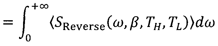
[0026]
FIG. 2Α compares the forward heat flux spectrum of the thermal rectification device of the first embodiment with that of blackbody radiation. The distance d between the first medium 11 and the second medium 12 was set to 100 nm, and the thickness t3 of the third medium 13 (amorphous silicon) was set to 1 nm. For facilitating comparison with blackbody radiation, the vertical axis of FIG. 2A is of logarithmic scale. As is understood from FIG. 2A, evanescent p-polarization provides heat flux whose intensity greatly
exceeds that of heat flux provided by blackbody radiation.
[0027]
FIG. 2B shows heat flux spectra in the forward biased state and the reverse biased state. As is understood from FIG. 2B, in the forward biased state, the heat flux spectrum has a peak at the wavelength of 10.6 μιη, and, in the reverse biased state, heat flux decays at the position of the peak.
Let us obtain conditions for generation of a forward heat flux peak. With (83)1/2co/c being sufficiently smaller than β , the imaginary part of the second term, the third term, and the fourth term of Eq. (4) become sufficiently small as compared with the real part of the second term of Eq. (4) . Therefore, Eq. (4) can be approximated as follows.
[Math. 10]
Dee TL ~l - Re (r31iP(TL)r30iPexp(-2Kmt3) (10)
The following conditions for maximizing the forward heat flux given by Eq. (8) are obtained by replacing the differential with respect to the thickness t3 of the third medium in Eq. (8) with zero.
[Math. 11]
1-Re (r31;P(TL)) r30pexp(-2Kmt3) = 0 (11)
[Math. 12]

Eq. (12) is solved, thereby yielding Eq. (1) mentioned above .
The rectification coefficient is defined as follows.
[Math. 13]

[0028]
The rectification coefficient was calculated for the case where the temperature TH was set to 500K, the
temperature TL was set to 300K, and the relative permittivity 83 and the thickness t3 of the third medium 13 were varied. FIG. 3A shows the relationship between the thickness t3 and the relative permittivity 83 for the maximum rectification coefficient. FIG. 3B shows the relationship between the maximum rectification coefficient and the thickness t3. As is understood from FIGS. 3A and 3B, even though the relative permittivity ε3 of the third medium is varied in the range of 2 to 14, by means of the thickness t3 being selected
appropriately according to the relative permittivity ε3 on the basis of the relationship of FIG. 3A, the rectification coefficient becomes constant around 0.7 as shown in FIG. 3B. Also, it is understood that Eq. (1) accurately expresses the relationship between the thickness t3 and the relative permittivity ε3 for the maximum rectification coefficient.
Second Embodiment
[0029]
FIG. 4 shows the configuration of a thermal
rectification device A20 according to a second embodiment of the present invention. In the thermal rectification device
A10 of the first embodiment, only the first medium 11 is coated with amorphous silicon, thereby having the third medium 13 thereon. In the thermal rectification device A20 of the second embodiment, amorphous silicon is coated on the main surface 22 of the second medium 12 on a side toward the first medium 11, thereby forming a fourth medium 14 having a thickness different from that of the third medium 13.
Configurational features identical in function with those of the first embodiment are denoted by like reference numerals or signs. The material of the fourth medium 14 may differ from that of the third medium 13 in temperature and frequency characteristics of permittivity. The employment of the configuration of the second embodiment provides a thermal rectification device whose degree of freedom of design is further improved and whose fabrication is further facilitated.
[0030]
In the above embodiments, the distance d between the main surface 21 of the first medium 11 and the main surface 22 of the second medium 12 is 100 nm. However, no particular limitation is imposed on the distance d so long as evanescent waves can be efficiently coupled. This is for the following reason: when the distance d is much less than the wavelength
(10.6 μηα) of evanescent waves generated through excitation of surface phonon polaritons, the evanescent waves are
efficiently coupled together, resulting in resonance between surface phonon polaritons on the two interfaces. For example, a distance d of 300 nm or less, 200 nm or less, 100 nm or
less, or a 50 nm or less can be used.
In the present invention, the third medium 13 and the fourth medium 14 can be of, in addition to the above- mentioned material, barium fluoride (BaF2) , strontium
fluoride (SrF2) , lead fluoride (PbF2), calcium fluoride (CaF2) , rubidium bromide (RbBr) , cesium bromide (CsBr) , cesium
chloride (CsCl) , potassium chloride (KC1) , or sodium chloride (NaCl) , for use with a material of the first and second media 11 and 12, such as SiC or Si02, whose real part of
permittivity is -1 or less in the frequency band of
evanescent waves generated through thermal excitation of surface phonon polaritons .
Particularly, in the case of the first and second media 11 and 12 of SiC, desirably, the third and fourth media 13 and 14 are of barium fluoride (BaF2) , strontium fluoride
(SrF2) , or calcium fluoride (CaF2) . In this case, forward heat flux can be increased in intensity, and the
rectification coefficient can be increased.
Industrial Applicability
[0031]
The present invention can be applied to devices which require unidirectional heat flow, such as heat sinks, heat storage devices, and heat retaining devices.
Claims
[Claim 1]
A thermal rectification device comprising a first medium and a second medium, the first and second media being coupled via evanescent waves generated by surface phonon polaritons thermally excited on surfaces of the first and second media, the first and second media being disposed with a gap formed therebetween for cutting off thermal conduction therebetween, heat transfer between the first and second media being performed mainly via the thermally excited evanescent waves,
wherein the first medium and the second medium are of the same material;
a third medium is provided on a surface of the first medium on a side toward the second medium; and
heat flux which flows from the second medium to the first medium in a first state in which the second medium has a first temperature TH and the first medium has a second temperature TL lower than the first temperature TH differs in intensity from heat flux which flows from the first medium to the second medium in a second state in which the first medium has the first temperature TH and the second medium has the second temperature TL.
[Claim 2]
A thermal rectification device according to claim 1, wherein a fourth medium is provided on a surface of the second medium on a side toward the first medium.
[Claim 3]
A thermal rectification device according to claim 1, wherein the third medium has a relative permittivity and a thickness such that
in the first state, there exists a wide first frequency range in which the resonance frequency of surface phonon polaritons thermally excited at the interface between the first medium and the third medium coincides with the
resonance frequency of surface phonon polaritons thermally excited on the surface of the second medium on the side toward the first medium; and
in the second state, there does not exist or does exist a second frequency range which is narrower than the first frequency range and in which the resonance frequency of surface phonon polaritons thermally excited at the interface between the first medium and the third medium coincides with the resonance frequency of surface phonon polaritons
thermally excited on the surface of the second medium.
[Claim 4]
A thermal rectification device according to claim 2, wherein the third medium and the fourth medium have a relative permittivity and a thickness, respectively, such that
in the first state, there exists a wide first frequency range in which the resonance frequency of surface phonon polaritons thermally excited at the interface between the first medium and the third medium coincides with the resonance frequency of surface phonon polaritons thermally excited at the interface between the second medium and the fourth medium; and
in the second state, there does not exist or does exist a second frequency range which is narrower than the first frequency range and in which the resonance frequency of surface phonon polaritons thermally excited at the interface between the first medium and the third medium coincides with the resonance frequency of surface phonon polaritons
thermally excited at the interface between the second medium and the fourth medium.
[Claim 5]
A thermal rectification device according to any one of claims 1 to 4, wherein heat flux which flows from the second medium to the first medium in the first state is larger in intensity than heat flux which flows from the first medium to the second medium in the second state.
[Claim 6]
A thermal rectification device according to any one of claims 1 to 5, wherein the gap between the first medium and the second medium is 300 nm or less.
[Claim 7]
A thermal rectification device according to any one of claims 1 to 6, wherein the relative permittivities of the first and - second media have a real part of -1 or less as measured in a working temperature range and a frequency band of the evanescent waves when heat transfer is performed via the evanescent waves.
[Claim 8]
A thermal rectification device according to any one of claims 1 to 7, wherein the first medium and the second medium are at least one of silicon carbide (SiC) , silicon dioxide
(S1O2) , and silicon (Si) doped with impurities.
[Claim 9]
A thermal rectification device according to any one of claims 1 to 8, wherein, when a direction in which heat flux of high intensity flows is defined as a forward direction and a direction in which heat flux of low intensity flows is defined as a reverse direction, the third medium has such a relative permittivity and thickness as to maximize heat flux of the forward direction.
[Claim 10]
A thermal rectification device according to claim 2 or 4, wherein, when a direction in which heat flux of high intensity flows is defined as a forward direction and a direction in which heat flux of low intensity flows is defined as a reverse direction, the fourth medium has such a relative permittivity and thickness as to maximize heat flux of the forward direction.
[Claim 11]
A thermal rectification device according to any one of claims 1 to 10, wherein a thickness t3 and a relative
permittivity ε3 of the third medium satisfy [Math. 1]
1 (e3 - 1)(ε3 2 - k 2)
t3 ~ 2k^ ln (ε3 + 1)|ε3 + ει|2 (1) where εχ is a relative permittivity of the first medium, km is 40k0 to 50k0, k0 = 2π/λ0, and λο is a wavelength of
evanescent waves which maximizes heat flux in a forward direction, which is a direction in which heat flux of higher intensity flows as compared with that in the opposite direction .
[Claim 12]
A thermal rectification device according to any one of claims 1 to 11, wherein the third medium is amorphous silicon and has a thickness t3 of 1 nm to 2 nm.
[Claim 13]
A thermal rectification device according to any one of claims 1 to 11, wherein the third medium is a material having a relative permittivity of 1.5 to 2.5 and has a thickness t3 of 5 nm to 20 nm.
[Claim 14]
A thermal rectification device according to any one of claims 1 to 13, wherein the third medium is at least one selected from the group consisting of barium fluoride (BaF2) , strontium fluoride (SrF2) , lead fluoride (PbF2), calcium fluoride (CaF2) , rubidium bromide (RbBr) , cesium bromide (CsBr) , cesium chloride (CsCl) , potassium chloride (KC1), and sodium chloride (NaCl) .
[Claim 15] A thermal rectification device according to claim 2 or 4, wherein the fourth medium is at least one selected from the group consisting of barium fluoride (BaF2) , strontium fluoride (SrF2), lead fluoride (PbF2), calcium fluoride (CaF2) , rubidium bromide (RbBr) , cesium bromide (CsBr) , cesium
chloride (CsCl) , potassium chloride (KC1), and sodium
chloride (NaCl) .
Priority Applications (1)
| Application Number | Priority Date | Filing Date | Title |
|---|---|---|---|
| US14/391,307 US9791183B2 (en) | 2012-04-20 | 2013-04-16 | Thermal rectification device |
Applications Claiming Priority (2)
| Application Number | Priority Date | Filing Date | Title |
|---|---|---|---|
| JP2012-096898 | 2012-04-20 | ||
| JP2012096898A JP5605391B2 (en) | 2012-04-20 | 2012-04-20 | Thermal rectification device |
Publications (1)
| Publication Number | Publication Date |
|---|---|
| WO2013157656A1 true WO2013157656A1 (en) | 2013-10-24 |
Family
ID=48793498
Family Applications (1)
| Application Number | Title | Priority Date | Filing Date |
|---|---|---|---|
| PCT/JP2013/061704 Ceased WO2013157656A1 (en) | 2012-04-20 | 2013-04-16 | Thermal rectification device |
Country Status (3)
| Country | Link |
|---|---|
| US (1) | US9791183B2 (en) |
| JP (1) | JP5605391B2 (en) |
| WO (1) | WO2013157656A1 (en) |
Families Citing this family (6)
| Publication number | Priority date | Publication date | Assignee | Title |
|---|---|---|---|---|
| JP6269008B2 (en) * | 2013-12-12 | 2018-01-31 | 株式会社豊田中央研究所 | Electromagnetic wave-surface polariton conversion element. |
| US9970714B2 (en) | 2016-05-11 | 2018-05-15 | Toyota Motor Engineering & Manufacturing North America, Inc. | Heat pipe heat flux rectifier |
| CN106546122B (en) * | 2016-10-11 | 2019-03-08 | 华中科技大学 | A near-field radiation heat transfer heat regulator |
| US11060804B2 (en) | 2017-02-15 | 2021-07-13 | Panasonic Intellectual Property Management Co., Ltd. | Thermal rectifier and thermal rectification unit |
| CN109974514B (en) * | 2017-12-28 | 2020-08-11 | 清华大学 | Thermal triode and thermal circuit |
| EP4622095A4 (en) * | 2022-11-15 | 2026-01-07 | Mitsubishi Electric Corp | NEAR-FIELD HEAT RADIATION POWER GENERATION ELEMENT |
Citations (1)
| Publication number | Priority date | Publication date | Assignee | Title |
|---|---|---|---|---|
| US20050247337A1 (en) * | 2004-05-04 | 2005-11-10 | Massachusetts Institute Of Technology | Surface plasmon coupled nonequilibrium thermoelectric devices |
Family Cites Families (6)
| Publication number | Priority date | Publication date | Assignee | Title |
|---|---|---|---|---|
| JPS61272591A (en) * | 1985-05-28 | 1986-12-02 | A Waaku Shiyotsupu:Kk | Heat-flow straightening element and container using same |
| JP4649389B2 (en) * | 2006-09-28 | 2011-03-09 | 株式会社東芝 | Magnetic refrigeration device and magnetic refrigeration method |
| WO2008042920A2 (en) * | 2006-10-02 | 2008-04-10 | The Regents Of The University Of California | Solid state thermal rectifier |
| US20100031990A1 (en) * | 2008-08-01 | 2010-02-11 | University Of Kentucky Research Foundation | Cascaded Photovoltaic and Thermophotovoltaic Energy Conversion Apparatus with Near-Field Radiation Transfer Enhancement at Nanoscale Gaps |
| US20110298333A1 (en) * | 2010-06-07 | 2011-12-08 | Pilon Laurent G | Direct conversion of nanoscale thermal radiation to electrical energy using pyroelectric materials |
| US8739859B2 (en) * | 2010-10-04 | 2014-06-03 | Toyota Motor Engineering & Manufacturing North America, Inc. | Reversible thermal rectifiers, temperature control systems and vehicles incorporating the same |
-
2012
- 2012-04-20 JP JP2012096898A patent/JP5605391B2/en not_active Expired - Fee Related
-
2013
- 2013-04-16 US US14/391,307 patent/US9791183B2/en not_active Expired - Fee Related
- 2013-04-16 WO PCT/JP2013/061704 patent/WO2013157656A1/en not_active Ceased
Patent Citations (1)
| Publication number | Priority date | Publication date | Assignee | Title |
|---|---|---|---|---|
| US20050247337A1 (en) * | 2004-05-04 | 2005-11-10 | Massachusetts Institute Of Technology | Surface plasmon coupled nonequilibrium thermoelectric devices |
Non-Patent Citations (5)
| Title |
|---|
| C. R. OTEY; W. T. LAU; S. FAN: "Thermal rectification through vacuum", PHYSICAL REVIEW LETTERS, vol. 104, 2010, pages 154301 |
| D. POLDER; M. VAN HOVE: "Theory of radiative heat transfer between closely spaced bodies", PHYSICAL REVIEW B, vol. 4, 1971, pages 3303 |
| S. BASU; M. FRANCOEUR: "Near-field radiative transfer based thermal rectification using doped silicon", APPLIED PHYSICS LETTERS, vol. 98, 2011, pages 113106 |
| S. BASU; M. FRANCOEUR: "Near-field radiative transfer based thermal rectification using doped silicon", APPLIED PHYSICS LETTERS, vol. 98, no. 11, 113106, 2011, pages 1 - 3, XP002711614 * |
| S. BASU; Z. M. ZHANG; C. J. FU: "Review of near-field thermal radiation and its application to energy conversion", INTERNATIONAL JOURNAL OF ENERGY RESEARCH, vol. 33, 2009, pages 1203 - 1232 |
Also Published As
| Publication number | Publication date |
|---|---|
| JP2013224781A (en) | 2013-10-31 |
| JP5605391B2 (en) | 2014-10-15 |
| US20150082810A1 (en) | 2015-03-26 |
| US9791183B2 (en) | 2017-10-17 |
Similar Documents
| Publication | Publication Date | Title |
|---|---|---|
| Li et al. | Transforming heat transfer with thermal metamaterials and devices | |
| Zhang et al. | Broadband nonreciprocal thermal emission | |
| Seletskiy et al. | Laser cooling in solids: advances and prospects | |
| Basu et al. | Near-field radiative heat transfer between doped silicon nanowire arrays | |
| Li et al. | Nanophotonic control of thermal radiation for energy applications | |
| Ito et al. | Experimental investigation of radiative thermal rectifier using vanadium dioxide | |
| WO2013157656A1 (en) | Thermal rectification device | |
| Chen et al. | Near-field enhanced negative luminescent refrigeration | |
| Cheng et al. | Zinc oxide single-crystal microtubes | |
| Santhanam et al. | Room temperature thermo-electric pumping in mid-infrared light-emitting diodes | |
| Huang et al. | Electrically tunable near-field radiative heat transfer via ferroelectric materials | |
| Liu et al. | Super-Planckian thermal radiation enabled by hyperbolic surface phonon polaritons | |
| Ben-Abdallah et al. | Heat flux splitter for near-field thermal radiation | |
| Deng et al. | Metamaterial thermal emitters based on nanowire cavities for high-efficiency thermophotovoltaics | |
| Karalis et al. | Temporal coupled-mode theory model for resonant near-field thermophotovoltaics | |
| Li et al. | Thin-film radiative thermal diode with large rectification | |
| Xu et al. | Highly efficient near-field thermal rectification between InSb and graphene-coated SiO2 | |
| Haeger et al. | Thermal properties of CsPbCl3 thin films across phase transitions | |
| US12435931B2 (en) | Radiative heatsink | |
| Mirmoosa et al. | Microgap thermophotovoltaic systems with low emission temperature and high electric output | |
| Wang et al. | Spectrally selective solar absorber with sharp and temperature dependent cut-off based on semiconductor nanowire arrays | |
| Li et al. | Radiative thermal diode via hyperbolic metamaterials | |
| Kumar et al. | Anisotropic electron–photon–phonon coupling in layered MoS2 | |
| Tian et al. | High temperature efficient, stable Si wafer-based selective solar absorbers | |
| Chelh et al. | DFT investigation of the structural, optoelectronic, thermoelectric, and thermodynamic properties of metal phosphides MP2 (M= Co, Rh, and Ir) |
Legal Events
| Date | Code | Title | Description |
|---|---|---|---|
| 121 | Ep: the epo has been informed by wipo that ep was designated in this application |
Ref document number: 13737437 Country of ref document: EP Kind code of ref document: A1 |
|
| WWE | Wipo information: entry into national phase |
Ref document number: 14391307 Country of ref document: US |
|
| NENP | Non-entry into the national phase |
Ref country code: DE |
|
| 122 | Ep: pct application non-entry in european phase |
Ref document number: 13737437 Country of ref document: EP Kind code of ref document: A1 |