WO2013153753A1 - 静圧気体軸受及びこの静圧気体軸受を用いた直動案内装置 - Google Patents
静圧気体軸受及びこの静圧気体軸受を用いた直動案内装置 Download PDFInfo
- Publication number
- WO2013153753A1 WO2013153753A1 PCT/JP2013/002077 JP2013002077W WO2013153753A1 WO 2013153753 A1 WO2013153753 A1 WO 2013153753A1 JP 2013002077 W JP2013002077 W JP 2013002077W WO 2013153753 A1 WO2013153753 A1 WO 2013153753A1
- Authority
- WO
- WIPO (PCT)
- Prior art keywords
- wall surface
- annular
- bearing
- base
- cylindrical
- Prior art date
- Legal status (The legal status is an assumption and is not a legal conclusion. Google has not performed a legal analysis and makes no representation as to the accuracy of the status listed.)
- Ceased
Links
Images















Classifications
-
- F—MECHANICAL ENGINEERING; LIGHTING; HEATING; WEAPONS; BLASTING
- F16—ENGINEERING ELEMENTS AND UNITS; GENERAL MEASURES FOR PRODUCING AND MAINTAINING EFFECTIVE FUNCTIONING OF MACHINES OR INSTALLATIONS; THERMAL INSULATION IN GENERAL
- F16C—SHAFTS; FLEXIBLE SHAFTS; ELEMENTS OR CRANKSHAFT MECHANISMS; ROTARY BODIES OTHER THAN GEARING ELEMENTS; BEARINGS
- F16C29/00—Bearings for parts moving only linearly
- F16C29/02—Sliding-contact bearings
- F16C29/025—Hydrostatic or aerostatic
-
- F—MECHANICAL ENGINEERING; LIGHTING; HEATING; WEAPONS; BLASTING
- F16—ENGINEERING ELEMENTS AND UNITS; GENERAL MEASURES FOR PRODUCING AND MAINTAINING EFFECTIVE FUNCTIONING OF MACHINES OR INSTALLATIONS; THERMAL INSULATION IN GENERAL
- F16C—SHAFTS; FLEXIBLE SHAFTS; ELEMENTS OR CRANKSHAFT MECHANISMS; ROTARY BODIES OTHER THAN GEARING ELEMENTS; BEARINGS
- F16C32/00—Bearings not otherwise provided for
- F16C32/06—Bearings not otherwise provided for with moving member supported by a fluid cushion formed, at least to a large extent, otherwise than by movement of the shaft, e.g. hydrostatic air-cushion bearings
- F16C32/0603—Bearings not otherwise provided for with moving member supported by a fluid cushion formed, at least to a large extent, otherwise than by movement of the shaft, e.g. hydrostatic air-cushion bearings supported by a gas cushion, e.g. an air cushion
- F16C32/0614—Bearings not otherwise provided for with moving member supported by a fluid cushion formed, at least to a large extent, otherwise than by movement of the shaft, e.g. hydrostatic air-cushion bearings supported by a gas cushion, e.g. an air cushion the gas being supplied under pressure, e.g. aerostatic bearings
- F16C32/0622—Bearings not otherwise provided for with moving member supported by a fluid cushion formed, at least to a large extent, otherwise than by movement of the shaft, e.g. hydrostatic air-cushion bearings supported by a gas cushion, e.g. an air cushion the gas being supplied under pressure, e.g. aerostatic bearings via nozzles, restrictors
-
- F—MECHANICAL ENGINEERING; LIGHTING; HEATING; WEAPONS; BLASTING
- F16—ENGINEERING ELEMENTS AND UNITS; GENERAL MEASURES FOR PRODUCING AND MAINTAINING EFFECTIVE FUNCTIONING OF MACHINES OR INSTALLATIONS; THERMAL INSULATION IN GENERAL
- F16C—SHAFTS; FLEXIBLE SHAFTS; ELEMENTS OR CRANKSHAFT MECHANISMS; ROTARY BODIES OTHER THAN GEARING ELEMENTS; BEARINGS
- F16C11/00—Pivots; Pivotal connections
- F16C11/04—Pivotal connections
- F16C11/06—Ball-joints; Other joints having more than one degree of angular freedom, i.e. universal joints
-
- F—MECHANICAL ENGINEERING; LIGHTING; HEATING; WEAPONS; BLASTING
- F16—ENGINEERING ELEMENTS AND UNITS; GENERAL MEASURES FOR PRODUCING AND MAINTAINING EFFECTIVE FUNCTIONING OF MACHINES OR INSTALLATIONS; THERMAL INSULATION IN GENERAL
- F16C—SHAFTS; FLEXIBLE SHAFTS; ELEMENTS OR CRANKSHAFT MECHANISMS; ROTARY BODIES OTHER THAN GEARING ELEMENTS; BEARINGS
- F16C2240/00—Specified values or numerical ranges of parameters; Relations between them
- F16C2240/40—Linear dimensions, e.g. length, radius, thickness, gap
-
- F—MECHANICAL ENGINEERING; LIGHTING; HEATING; WEAPONS; BLASTING
- F16—ENGINEERING ELEMENTS AND UNITS; GENERAL MEASURES FOR PRODUCING AND MAINTAINING EFFECTIVE FUNCTIONING OF MACHINES OR INSTALLATIONS; THERMAL INSULATION IN GENERAL
- F16C—SHAFTS; FLEXIBLE SHAFTS; ELEMENTS OR CRANKSHAFT MECHANISMS; ROTARY BODIES OTHER THAN GEARING ELEMENTS; BEARINGS
- F16C2240/00—Specified values or numerical ranges of parameters; Relations between them
- F16C2240/40—Linear dimensions, e.g. length, radius, thickness, gap
- F16C2240/42—Groove sizes
-
- F—MECHANICAL ENGINEERING; LIGHTING; HEATING; WEAPONS; BLASTING
- F16—ENGINEERING ELEMENTS AND UNITS; GENERAL MEASURES FOR PRODUCING AND MAINTAINING EFFECTIVE FUNCTIONING OF MACHINES OR INSTALLATIONS; THERMAL INSULATION IN GENERAL
- F16C—SHAFTS; FLEXIBLE SHAFTS; ELEMENTS OR CRANKSHAFT MECHANISMS; ROTARY BODIES OTHER THAN GEARING ELEMENTS; BEARINGS
- F16C32/00—Bearings not otherwise provided for
- F16C32/06—Bearings not otherwise provided for with moving member supported by a fluid cushion formed, at least to a large extent, otherwise than by movement of the shaft, e.g. hydrostatic air-cushion bearings
- F16C32/0662—Details of hydrostatic bearings independent of fluid supply or direction of load
- F16C32/0666—Details of hydrostatic bearings independent of fluid supply or direction of load of bearing pads
Definitions
- the present invention relates to a static pressure gas bearing and a linear motion guide device using the static pressure gas bearing.
- a linear motion guide device using a static pressure gas bearing with little friction is used for a positioning device for a work table.
- a lubricating film of compressed air is interposed between a movable table as a work table and a guide rail as a guide member. It is configured to be moved by contact.
- the throttle type of the air outlet of the static pressure gas bearing used in this linear motion guide device there are a porous throttle, a surface throttle, an orifice throttle, a self-contained throttle, etc., and a static pressure gas bearing equipped with these throttle types Are used while adjusting the load capacity, bearing rigidity, etc. according to the respective applications.
- Patent Document 1 a static body is fixed to either a supported body or a support body, and the support body is movably supported by pressurized air supplied to the bearing surface via the bearing member.
- a pressurized gas bearing pad as a bearing member, a type of carbon graphite-based material has been proposed in which the diameter of material particles is substantially uniform and the uniformity of open pores can be obtained.
- Patent Document 2 discloses a porous material produced by adjusting the diameter and distribution of through-holes so that a desired amount of air permeation can be obtained by joining a porous material and a preform on the preform.
- a static pressure gas bearing that includes a surface constriction layer made of a plate, ejects gas through the surface constriction layer, and supports the supported body by the static pressure.
- the present applicant has firstly provided a plurality of air outlets having a self-contained throttle shape or an orifice throttle shape on the upper surface, and a lower surface.
- Synthetic resin bearing members each having an air supply groove communicating with the plurality of air outlets, and an air supply connected to the lower surface of the bearing member so as to cover the air supply groove and communicating with the air supply groove
- Patent Document 3 A hydrostatic gas bearing in which a bearing base having a mouth is integrated has been proposed (Patent Document 3).
- a synthetic resin bearing member that forms the hydrostatic gas bearing can be formed by injection molding using a mold, and machining is unnecessary.
- the structure of the bearing base also forms an air supply port communicating with the bearing body, and the static pressure gas bearing can be assembled by simply joining the bearing body and the bearing base. This enables mass production of bearings and provides an inexpensive static pressure gas bearing.
- the air outlet in the static pressure gas bearing described in Patent Document 3 is formed by injection molding using a mold, it has a relatively large diameter of about 0.2 to 0.4 mm. There is a risk that it will be in the shape of an orifice or orifice, and there is a risk that self-excited vibration will occur due to the excessive amount of air supply from the air outlet, and the support of the supported body by the hydrostatic gas bearing will become unstable and will also be put to practical use. There is a need for improvement.
- the present invention has been made in view of the above-mentioned points, and an object of the present invention is to provide an inexpensive static pressure gas that can suppress the occurrence of self-excited vibration and can stably support a supported body.
- An object of the present invention is to provide a bearing and a linear guide device using the static pressure gas bearing.
- the hydrostatic gas bearing of the present invention has a base, an annular protrusion integrally projecting from one surface of the base, and one end opening at the projecting end surface of the annular protrusion, while the other end of the base
- a bearing base made of a synthetic resin having an air supply passage provided in the base and the annular projecting portion and opening on the outer peripheral surface, and a bearing base formed on one surface facing one surface of the base
- a plurality of air as a self-contained aperture that communicates with the annular recess at one end and the annular recess at one end and opens into the annular recess at the other end.
- the self-excited vibration damping mechanism is formed on the bearing base or on the bearing body or by the cooperation of the bearing base and the bearing body.
- the air chamber has one end communicating with the air chamber at one end, and at least one throttle hole opening at the other surface of the bearing body at the other end.
- the annular protrusion of the synthetic resin bearing base is received in the annular recess of the synthetic resin bearing body, and the outer peripheral surface and inner peripheral surface of the annular protrusion are Since it is welded and joined to the outer inner peripheral surface and the inner inner peripheral surface of the bearing body that defines the annular recess, the synthetic resin bearing body and the bearing base are firmly integrated, and the bearing base or An air chamber formed in the bearing body or by the cooperation of the bearing base and the bearing body, and at least one throttle hole that communicates with the air chamber at one end and opens at the other surface of the bearing body at the other end.
- the self-excited vibration damping mechanism can suppress the generation of self-excited vibration due to air blowing from the air blowing hole through the annular concave groove, so that the supported body is stably supported by the static pressure gas bearing. Can be made.
- the annular groove is at least 0.3 mm wide, preferably 0.3-0.1 mm wide and at least 0.01 mm deep, preferably 0.01-0.
- the air blowing hole has a diameter of at least 30 ⁇ m at one end thereof, preferably a diameter of 30 to 120 ⁇ m.
- At least one of the annular concave groove, the air blowing hole, and the throttle hole is preferably formed by laser processing with a processing laser laser selected from a carbon dioxide laser, a YAG laser, a UV laser, an excimer laser, and the like. Yes.
- annular groove, air blowing hole and throttle hole are formed by laser processing, these can be formed instantaneously compared to machining such as cutting, and mass production becomes possible, It can be manufactured at low cost.
- the outer peripheral surface of the annular projecting portion of the bearing base gradually expands outward from the cylindrical outer wall surface continuously to the cylindrical outer wall surface.
- An inner peripheral surface of the projecting portion includes a cylindrical inner wall surface, an annular frustoconical inner wall surface that is continuous with the cylindrical inner wall surface and gradually reduces inward from the cylindrical inner wall surface, and the frustoconical inner wall surface
- a cylindrical inner wall surface continuously connected to one surface of the base portion and having a smaller diameter than the cylindrical inner wall surface, and an outer inner peripheral surface defining the annular recess of the bearing body is It has an outer cylindrical inner wall surface with an annular periphery that defines the outer edge of the open end, and defines an annular recess in the bearing body
- the inner inner circumferential surface has an inner cylindrical inner wall surface having a peripheral edge that defines the inner edge of the opening end of the annular recess, and the bearing body has an outer cylindrical inner wall surface of the outer circumferential surface of the annular protrusion.
- the inner cylindrical inner wall surface is fitted to the cylindrical outer wall surface and the inner cylindrical inner wall surface of the annular protruding portion, and the annular peripheral edge of the outer cylindrical inner wall surface defining the outer edge of the opening end of the annular recess is annularly projected.
- the outer peripheral surface of the truncated cone is in contact with the outer peripheral surface of the truncated cone, and the inner peripheral surface of the inner cylindrical surface defining the inner edge of the opening of the annular recess is brought into contact with the inner surface of the truncated cone. Then, it is welded and joined to the annular projecting portion by ultrasonic welding at a portion in contact with the annular projecting portion and integrated with the bearing base.
- the outer peripheral surface of the annular projection of the bearing base is gradually expanded outward from the cylindrical outer wall surface continuously with the cylindrical outer wall surface.
- the inner peripheral surface of the annular protrusion is formed by connecting a cylindrical inner wall surface, an annular frustoconical inner wall surface that is continuous with the cylindrical inner wall surface and gradually shrinks inward from the cylindrical inner wall surface,
- a cylindrical inner wall surface continuous with the wall surface and connected to one surface of the base and having a diameter smaller than that of the cylindrical inner wall surface, and an outer inner circumferential surface defining the annular recess of the bearing body is an outer cylindrical surface
- An inner wall and an annular wall that gradually expands from the inner wall surface of the outer cylinder and that defines the outer edge of the open end of the annular recess.
- An inner fringe inner wall surface having an edge, and an inner inner circumferential surface defining the annular recess of the bearing body is gradually reduced in diameter from the inner cylindrical inner wall surface and the inner cylindrical inner wall surface.
- an inner frustoconical inner wall surface having an annular peripheral edge defining an inner edge of the opening end of the annular recess and the bearing body has an outer cylindrical inner wall surface that is an outer periphery of the annular protrusion. Fit the inner cylindrical inner wall surface to the inner cylindrical inner wall surface of the annular protrusion, and the outer frustoconical inner wall surface to the outer frustoconical outer wall surface, and the inner frustoconical inner wall surface to the inner cylindrical outer wall surface. Each is brought into contact with the inner wall surface of the truncated cone, and is welded and joined to the annular projection by ultrasonic welding at a portion contacting the annular projection and integrated with the bearing base.
- the air chamber has one surface of the base portion, one surface of the bearing body facing the one surface of the base portion, a frustoconical inner wall surface of the inner peripheral surface of the annular projecting portion of the bearing base, and a small-diameter cylinder. It may be provided with a space defined by the inner wall surface and formed by the cooperation of the bearing base and the bearing body. Instead, one surface of the base portion and one surface of the base portion face each other. A space defined by one surface of the bearing body and a small cylindrical inner wall surface of the bearing base and formed by the cooperation of the bearing base and the bearing body. The hole may open to a void at one end.
- the air chamber may be open at one surface of the bearing body and may have a recess formed in the bearing body. In this case, the throttle hole opens at the recess at one end. Good.
- the bearing body is formed on the other surface in addition to the annular groove, and a large-diameter annular groove surrounding the annular groove outside the annular groove, A plurality of first radial grooves, one end of which opens into the annular groove and the other end of which opens into the large-diameter groove, and the other side of the annular groove.
- the static pressure gas bearing of the present invention may further include a sphere receiving means provided on the bearing base and having a sphere receiving recess, and the sphere receiving means opens on the other surface of the base. Even if it has a truncated conical recess formed in the base as a sphere receiving recess, it may have a hemispherical recess formed in the bearing base as an opening in the other surface of the base as a sphere receiving recess. And a piece having a truncated cone concavity that is open and fitted in a cylindrical recess formed on the other surface of the base and fitted in a cylindrical recess formed in the base. And a piece having a hemispherical recess opened as a sphere receiving recess that is open and fitted in a cylindrical recess formed in the base and opened on the other surface of the base. Good.
- the sphere of the ball stud may be slidably disposed in contact with the base or the piece in the sphere receiving recess, and in such a case, An automatic centering function around the sphere is added to the static pressure gas bearing.
- the static pressure gas bearing to which such an automatic alignment function is added is suitable for use in a linear motion guide device as a positioning device for a work table.
- the linear motion guide device of the present invention includes a guide member having an upper surface guide surface and both side guide surfaces, a pair of upper plates disposed on the outer side of the guide member and facing the upper surface guide surface, and facing both side guide surfaces.
- a movable table provided with a side plate, a ball stud standing on at least one of a lower surface of the upper plate of the movable table and an inner surface of each of the pair of side plates with a sphere facing the guide member, and the ball stud
- the above-mentioned hydrostatic gas bearing having a sphere-receiving means and a movable table other than the at least one surface, and a movable table other than the at least one surface.
- the ball stud sphere has a bearing base of the static pressure gas bearing having the sphere receiving means as a center. At least one of the static pressure gas bearings that is received in each of the sphere receiving portions of the sphere receiving means of the static pressure gas bearing so as to be swingable with respect to the ball stud and does not necessarily have the sphere receiving means.
- the bases of the bearing bases of the two hydrostatic gas bearings are fixed to the lower surface of the upper plate of the movable table and the inner surfaces of the pair of side plates other than the at least one surface.
- the bearing gap between the other surface of the bearing body and the guide surface is obtained by injecting compressed air from the plurality of air blowing holes of the bearing body onto the guide surface of the guide member.
- the movable table can be held in a non-contact state with respect to the guide surface by an air lubricating film formed on the order of several ⁇ m to several tens of ⁇ m.
- the air chamber communicating with the bearing gap between the other surface of the bearing body and the guide surface via the throttle hole exerts a vibration damping action, the occurrence of self-excited vibration can be suppressed, and the other of the bearing body Even if the bearing gap between the bearing surface and the guide surface is uneven and a pressure difference occurs in the bearing gap, the static pressure gas bearing is automatically aligned in the direction in which the bearing gap becomes uniform due to the pressure difference. , Because the other surface of the bearing body is kept parallel to the guide surface.
- the accuracy of parts such as parallelism and perpendicularity of the inner member and movable table can be made relatively coarse, and in addition to the low cost of the static pressure gas bearing itself, an inexpensive linear motion guide device can be provided. .
- the bearing body is preferably formed from a thermoplastic synthetic resin such as polyacetal resin, polyamide resin, polyphenylene sulfide resin, and the bearing base is composed of polyacetal resin, polyamide resin, polyphenylene. It is formed from a thermoplastic synthetic resin such as sulfide resin or a thermoplastic synthetic resin containing reinforcing filler containing 30 to 50% by mass of glass fiber, glass powder, carbon fiber or inorganic filler in these thermoplastic synthetic resins. Is preferred.
- These synthetic resin bearing bodies and bearing bases may be formed by machining a synthetic resin material or by injection molding using a mold.
- the generation of self-excited vibration can be suppressed, and mass production capable of stably supporting a supported body is possible, and an inexpensive static pressure gas bearing and this static pressure gas bearing are used.
- a linear motion guide device can be provided.
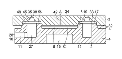
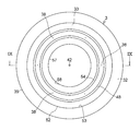
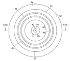
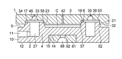
- FIG. 1 is an explanatory plan view of a preferred example of an embodiment of the present invention.
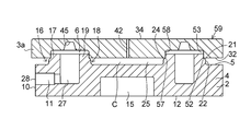
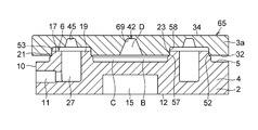
- 2 is a cross-sectional explanatory view taken along the line II-II in FIG.
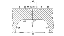
- FIG. 3 is a partially enlarged cross-sectional explanatory view of FIG.
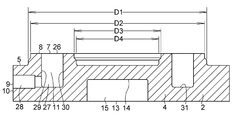
- FIG. 4 is an explanatory plan view of the bearing base.
- FIG. 5 is a cross-sectional explanatory view taken along the line VV in FIG. 6 is a partially enlarged cross-sectional explanatory view of FIG.
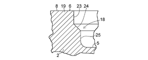
- FIG. 7 is a partially enlarged cross-sectional explanatory view of FIG.
- FIG. 8 is an explanatory bottom view of the bearing body.
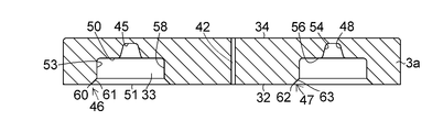
- FIG. 9 is a cross-sectional explanatory view taken along line IX-IX in FIG. FIG.
- FIG. 10 is an explanatory plan view of the assembly of the bearing body and the bearing base.
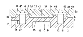
- 11 is a cross-sectional explanatory view taken along the line XI-XI in FIG.
- FIG. 12 is a partially enlarged cross-sectional explanatory view of FIG.
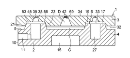
- FIG. 13 is a cross-sectional explanatory view of a preferred example of another embodiment of the bearing body.
- FIG. 14 is a cross-sectional explanatory view of the assembly of the bearing body element and the bearing base body shown in FIG.
- FIG. 15 is a partially enlarged cross-sectional explanatory view of FIG.
- FIG. 16 is a bottom view for explaining a preferred example of another embodiment of the bearing body.
- 17 is a cross-sectional explanatory view taken along line XVII-XVII in FIG.
- FIG. 18 is an explanatory cross-sectional view of the assembly of the bearing body element and the bearing base body shown in FIG.
- FIG. 19 is a cross-sectional explanatory view of a preferred example of another embodiment of the present invention.
- FIG. 20 is an explanatory bottom view of a preferable example of another embodiment of the bearing body.
- 21 is a cross-sectional explanatory view taken along the line XXI-XXI in FIG.
- FIG. 22 is an explanatory plan view of the assembly of the bearing body element and the bearing base body shown in FIG. 23 is a cross-sectional explanatory view taken along line XXIII-XXIII in FIG.
- FIG. 24 is an explanatory plan view of a preferred example of another embodiment of the present invention.
- FIG. 25 is a cross-sectional explanatory view taken along line XXV-XXV in FIG.
- FIG. 26 is an explanatory plan view of a preferred example of another embodiment of the bearing body.
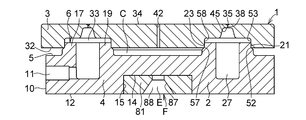
- FIG. 27 is a cross-sectional explanatory view of a preferable example of the piece.
- FIG. 28 is a cross-sectional explanatory view of a preferred example of another embodiment of the present invention using the bearing base to which the piece shown in FIG. 27 is fitted and fixed.
- FIG. 29 is a cross-sectional explanatory view of a static pressure gas bearing in which an automatic alignment function is added to the example shown in FIG.
- FIG. 30 is a cross-sectional explanatory view of another preferred example of the piece.
- FIG. 31 is a cross-sectional explanatory view of a preferred example of another embodiment of the present invention using the bearing base to which the piece shown in FIG. 30 is fitted and fixed.
- FIG. 32 is a cross-sectional explanatory view of a static pressure gas bearing obtained by adding an automatic alignment function to the example shown in FIG.
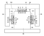
- FIG. 33 is a cross-sectional explanatory view of a preferred example of an embodiment of a linear motion guide device using a static pressure gas bearing.
- the static pressure gas bearing 1 is preferably made of a thermoplastic synthetic resin such as polyacetal resin (POM), polyamide resin (PA), polyphenylene sulfide resin (PPS), or a thermoplastic synthetic resin such as glass.
- a synthetic resin bearing base 2 made of a thermoplastic synthetic resin containing reinforcing filler containing 30 to 50% by mass of fiber, glass powder, carbon fiber or inorganic filler, and integrally welded to the bearing base 2
- a bearing body 3 made of a synthetic resin, preferably made of a thermoplastic synthetic resin such as a polyacetal resin, a polyamide resin, or a polyphenylene sulfide resin.
- the bearing base 2 has a base portion 4, an annular projecting portion 6 integrally projecting from one circular surface 5 of the base portion 4 in plan view, and an annular shape at one end 7.
- the protrusion 6 is open at the circular protrusion end surface 8 in plan view, while the other end 9 is open at the flat surface portion 10 of the cylindrical outer peripheral surface of the base 4 and is provided at the base 4 and the annular protrusion 6.
- An air passage 11 and an opening surface 13 having a circular shape in plan view are provided at the central portion of the other surface 12 of the base portion 4 having a circular shape in plan view, and are provided in the central portion and defined by a bottom surface 14 having a circular shape in plan view.
- a cylindrical recess 15 is provided.
- the annular protrusion 6 includes an outer annular protrusion 17 having an outer peripheral surface 16 and an inner annular protrusion 19 having an inner peripheral surface 18.
- the outer peripheral surface 16 of the outer annular protrusion 17 has a cylindrical outer wall surface 20 and an annular wharf that is continuous with the cylindrical outer wall surface 20 and gradually expands outward from the cylindrical outer wall surface 20. It has a conical outer wall surface 21 and a cylindrical outer wall surface 22 that is continuous with the frustoconical outer wall surface 21 and is continuous with one surface 5 of the base 4 and has a larger diameter than the cylindrical outer wall surface 20.
- the inner peripheral surface 18 of the inner annular projecting portion 19 is a cylindrical inner wall surface 23 and an annular flange gradually reducing the diameter inward from the cylindrical inner wall surface 23 continuously to the cylindrical inner wall surface 23.
- the head cone inner wall surface 24 and the frustoconical inner wall surface 24 are connected to one surface 5 of the base 4 and have a cylindrical inner wall surface 25 having a smaller diameter than the cylindrical inner wall surface 23.
- the air supply passage 11 provided in the bearing base 2 opens at the projecting end surface 8 at one end 7 of the annular shape as the annular opening 26 and has a bottomed circle provided at the base 4 and the annular projecting portion 6.
- An annular recess 27 is provided in the base 4 and communicates with the annular recess 27 at one end, and at the other end which is also the other end 9 of the air supply passage 11 at the flat surface portion 10 of the cylindrical outer peripheral surface of the base 4.
- an air supply opening 28 which is open.
- the annular recess 27 is defined by an outer cylindrical inner wall surface 29 of the base portion 4, an inner cylindrical inner wall surface 30 of the base portion 4 facing the outer cylindrical inner wall surface 29, and an annular bottom wall surface 31 of the base portion 4.
- the air supply port 28 is opened at one end by an outer cylindrical inner wall surface 29 and communicates with the annular recess 27.
- the bearing body 3 is formed on one surface 32 having a circular shape in a plan view facing the one surface 5 of the base portion 4, and the annular shape of the bearing base 2.
- An annular recess 33 that receives the protrusion 6, an annular recess 35 that opens on the other surface 34 that is circular in plan view, an end 36 that communicates with the annular recess 35, and an annular recess 33 at the other end 37.
- a plurality of air blowing holes 38 that are open to the outside and a cylindrical outer peripheral surface 39.
- the annular groove 35 defined by the annular bottom surface 43 of the bearing body 3 and the pair of cylindrical surfaces 44 facing each other has a width W of at least 0.3 mm and a width of at least 0.01 mm.
- the air blowing hole 38 has a diameter D of at least 30 ⁇ m from one end 36 to the other end 37 in this example, and has an annular recess 33 and an annular groove 35.
- a self-contained diaphragm is formed between
- the annular recess 33 is connected to an annular ceiling surface 45 where the other end 37 of the air blowing hole 38 opens, an outer inner peripheral surface 46 connected to the outer edge of the ceiling surface 45, and an inner edge of the ceiling surface 45.
- the inner inner peripheral surface 47 is defined.
- An outer inner peripheral surface 46 defining the annular recess 33 is formed on an annular frustoconical outer wall surface 48 having a small-diameter edge connected to an outer edge of the ceiling surface 45, and a large-diameter edge of the frustoconical outer wall surface 48.
- An annular step wall surface 50 having a small-diameter edge that is connected and facing the protruding end surface 8 of the outer annular protrusion 17 with a gap 49, and a large-diameter edge of the step wall surface 50.
- an outer cylindrical inner wall surface 53 having an annular peripheral edge 52 that defines the outer edge of the circular open end 51 of the annular recess 33.
- An inner inner peripheral surface 47 defining the annular recess 33 is formed on an annular frustoconical inner wall surface 54 having a large-diameter edge connected to the inner edge of the ceiling surface 45, and a small-diameter edge of the frustoconical inner wall surface 54.
- An annular step wall surface 56 having a large-diameter edge that is connected and facing the protruding end surface 8 of the inner annular protrusion 19 with a gap 55, and a small-diameter edge of the step wall surface 56.
- an inner cylindrical inner wall surface 58 having an annular peripheral edge 57 that defines the inner edge of the circular open end 51 of the annular recess 33.
- the static pressure gas bearing 1 further includes a self-excited vibration damping mechanism A that attenuates self-excited vibration caused by blowing air from the air blowing hole 38 through the annular concave groove 35.
- the air chamber B includes one surface 5 of the base 4, one surface 32 of the bearing body 3 facing the surface 5, a frustoconical inner wall surface 24 of the inner peripheral surface 18 of the annular protrusion 6 of the bearing base 2, and
- the space C is defined by the small-diameter cylindrical inner wall surface 25 and formed by the cooperation of the bearing base 2 and the bearing body 3, and the throttle hole 42 opens into the space C at one end 40. .
- the bearing body 3 has an outer cylindrical inner wall surface 53 on the outer cylindrical surface 20 of the outer annular projection 17 and an inner cylindrical inner wall surface 58 on the inner cylindrical surface 23 of the inner annular projection 19.
- the annular peripheral edge 52 of the outer cylindrical inner wall surface 53 that fits the contact and defines the outer edge of the opening end 51 of the annular recess 33 is formed on the frustoconical outer wall surface 21 of the outer peripheral surface 16 of the outer annular protrusion 17.
- the annular peripheral edge 57 of the inner cylindrical inner wall surface 58 that defines the inner edge of the opening end 51 of the 33 is brought into contact with the frustoconical inner wall surface 24 of the inner peripheral surface 18 of the inner annular protrusion 19, respectively.
- the peripheral edge 52 is formed by ultrasonic welding, that is, a so-called shear joint, at a portion where the peripheral edge 52 and the frustoconical outer wall surface 21 are in contact with each other and a portion where the peripheral edge 57 and the frustoconical inner wall surface 24 are in contact with each other.
- the peripheral edge 52 is formed by ultrasonic welding, that is, a so-called shear joint, at a portion where the peripheral edge 52 and the frustoconical outer wall surface 21 are in contact with each other and a portion where the peripheral edge 57 and the frustoconical inner wall surface 24 are in contact with each other.
- the portion that contacts the outer cylindrical wall surface 20 of the outer cylindrical inner wall surface 53 and the inner cylindrical wall surface 23 of the inner cylindrical inner wall surface 58 It is welded and joined to the bearing base 2 at a part to be integrated with the bearing base 2.
- the bearing body 3 is welded and joined to the outer peripheral surface 16 and the inner peripheral surface 18 of the annular protrusion 6 at the outer inner peripheral surface 46 and the inner inner peripheral surface 47 that define the annular recess 33, and is integrated with the bearing base 2.
- one surface 5 of the shaft base 4 one surface 32 of the bearing body 3 facing the one surface 5, and the frustoconical inner wall surface 24 of the inner peripheral surface 18 of the inner annular protrusion 19 of the bearing base 2.
- the void C of the air chamber B defined by the small-diameter cylindrical inner wall surface 25 is formed.
- the annular groove 35 having a width W on the surface 34 of the bearing body 3 of at least 0.3 mm and a depth d of at least 0.01 mm, and the one end 36 open to the annular groove 35.
- a plurality of self-drawing air blowing holes 38 having a diameter of at least 30 ⁇ m that open into the annular recess 33 may be formed instantaneously by, for example, laser processing.
- the bearing body 3 includes a portion where the peripheral edge 52 and the frustoconical outer wall surface 21 are in contact, a portion where the peripheral edge 57 and the frustoconical inner wall surface 24 are in contact, and an outer cylindrical inner wall surface 53.
- Mass production is possible because the portion in contact with the cylindrical outer wall surface 20 and the portion in contact with the inner cylindrical inner wall surface 58 and the cylindrical inner wall surface 23 are welded and bonded to the bearing base 2 instantaneously and hermetically by ultrasonic welding. In addition, it can be made inexpensive.
- a synthetic resin bearing base 2 as shown in FIGS. 4 to 7 and a central portion of one surface 32 are used.
- One throttle hole 42 that is opened and opened at the center of the other surface 34 is formed in advance, but the annular concave groove 35 and the plurality of air blowing holes 38 are not formed.
- Such a synthetic resin-made bearing body element 3a is prepared.
- one surface 5 of the base 4 is made to face one surface 32 of the bearing body 3 and the bearing base 2 is annular.
- the protrusion 6 is received in the annular recess 33 of the bearing body 3, and the annular peripheral edge 52 of the outer cylindrical inner wall surface 53 that defines the outer edge of the opening end 51 of the annular recess 33 is connected to the outer peripheral surface 16 of the outer annular protrusion 17.
- An inner edge of the opening end 51 of the annular recess 33 is defined on the outer wall 21 of the truncated cone.
- the annular peripheral edge 57 of the side cylindrical inner wall surface 58 is brought into contact with the frustoconical inner wall surface 24 of the inner peripheral surface 18 of the inner annular protrusion 19 to form an assembly 59 of the bearing body 3a and the bearing base 2. .
- a tool horn (not shown) is pressed against the surface 34 of the bearing body 3a in the assembly 59 to apply pressure 0.098 to 0.60 MPa, vibration amplitude 20 to 80 ⁇ m, and transmission time 0.1 to 1.5 seconds.
- the ultrasonic vibration is applied under the welding condition of the hold time of 0.5 to 1.0 seconds, and the contact portion between the peripheral edge 52 and the frustoconical outer wall surface 21 and the contact portion between the peripheral edge 57 and the frustoconical inner wall surface 24 are
- the shear joint is welded and joined with a welding allowance X in the radial direction and a welding allowance Y in the entry direction, and the bearing base 2 and the bearing body 3a are joined and integrated.
- the diameter of the cylindrical outer wall surface 22 of the outer annular projection 17 of the bearing base 2 formed of polyphenylene sulfide resin containing 30% by mass of glass fiber is D1
- the diameter of the cylindrical outer wall surface 20 is D2
- the inner annular projection is D1
- the diameter of the cylindrical inner wall surface 23 of the portion 19 is D3
- the diameter of the cylindrical inner wall surface 25 is D4
- the diameter of the outer cylindrical inner wall surface 53 of the annular recess 33 of the bearing body 3a formed of polyphenylene sulfide resin is d1
- the assembly 59 of the bearing base 2 and the bearing body 3a having the following dimensions is integrated by ultrasonic welding under the following welding conditions. An example will be described.
- the assembly 59 of the bearing base body 2 and the bearing body 3a ultrasonically welded under the above-mentioned dimensions and welding conditions is a joint between the peripheral edge 52 and the frustoconical outer wall surface 21 and the frustoconical part with the peripheral edge 57. It was confirmed that the joint portion with the inner wall surface 24 was welded and joined with good airtightness and joined and integrated with strong welding strength.
- the surface 34 of the bearing body 3a in the assembly 59 thus joined and integrated is irradiated with a laser by a laser processing machine to have a width W of 0.3 to 1.0 mm and a depth of d 0.01 to 0.05 mm.
- An annular groove 35 and an annular bottom surface 43 defining the annular groove 35 have a diameter of at least 30 ⁇ m, preferably 30 to 120 ⁇ m, which penetrates the bearing body 3 from the annular bottom surface 43 and opens to the annular recess 33 at the ceiling surface 45.
- a plurality of self-drawing air blowing holes 38 are formed.
- the processing laser to be used is selected from a carbon dioxide laser, a YAG laser, a UV laser, an excimer laser, and the like, and preferably a carbon dioxide laser is used.
- An annular groove 35 having a central diameter of 30 mm, a width of 0.5 mm, and a depth of 0.05 mm uses a carbon dioxide laser with a laser output of 9.5 W, and has a scanning speed of 1000 mm / s and the number of overprints of 1 It can be formed and processed on the surface 34 of the bearing body 3a made of polyphenylene sulfide resin with a processing time of 2 seconds, and the bearing body element can be formed on the annular bottom surface 43 of the annular groove 35 from the annular bottom surface 43.
- the self-drawn air blow hole 38 having a diameter of 0.065 mm (65 ⁇ m) that penetrates the body 3a and opens to the annular recess 33 at the ceiling surface 45 has a laser output of 14 W and a processing time of 15 seconds, and is 10 in the circumferential direction. Ten pieces could be processed at evenly spaced positions.
- the outer inner peripheral surface 46 includes the frustoconical outer wall surface 48, the stepped wall surface 50, and the outer cylindrical inner wall surface 53
- the inner inner peripheral surface 47 is the frustoconical inner wall surface 54, the stepped wall.
- the inner wall surface 56 and the inner cylindrical inner wall surface 58 are provided.
- the outer inner circumferential surface 46 includes a frustoconical outer wall surface 48, a stepped wall surface 50 and
- an annular peripheral edge 60 which is connected to one end of the outer cylindrical inner wall surface 53 and gradually increases in diameter from the one end and which defines the outer edge of the opening end 51 of the annular recess 33 is provided.
- the inner inner circumferential surface 47 further includes a frustoconical inner wall surface 54, a stepped wall surface 56, and an inner cylindrical inner wall surface 58, and an inner cylindrical inner wall surface 58. It is connected to one end and gradually decreases in diameter from the one end, and the annular recess 33
- An inner frustoconical inner wall surface 63 having an annular peripheral edge 62 that defines the inner edge of the mouth end 51 may be further provided, and the set of the bearing body 3a and the base portion 4 shown in FIGS.
- the bearing body 3 includes the outer cylindrical inner wall surface 53 on the cylindrical outer wall surface 20 of the outer circumferential surface 16 of the outer annular projecting portion 17, and the inner cylindrical inner wall surface 58 on the inner circumferential surface 18 of the inner annular projecting portion 19.
- the outer frustoconical inner wall surface 61 is fitted to the wall surface 23
- the outer frustoconical outer wall surface 21 of the outer annular projection 17 is the outer frustoconical outer wall surface 21, and the inner frustoconical inner wall surface 63 is the inner circumference of the inner annular projection 19.
- the bearing body 3a is in contact with the inner surface 24 of the truncated cone of the surface 18, and the bearing body 3a is in contact with each other, that is, the portion of contact between the outer truncated cone inner wall surface 61 and the outer truncated cone wall surface 21.
- the inner frustoconical inner wall 63 and the frustoconical inner wall 24 come into contact with each other.
- the air chamber B includes one surface 5 of the base portion 4, one surface 32 of the bearing body 3 facing the one surface 5, and an inner annular protrusion of the bearing base 2.
- the space C is defined by the small-diameter cylindrical inner wall surface 25 of the inner peripheral surface 18 of the portion 19 and is formed by the cooperation of the bearing base 2 and the bearing body 3a.
- the outer frustoconical inner wall surface 61 is brought into contact with the outer frustoconical outer wall surface 21 and the inner frustoconical inner wall surface 63 is brought into contact with the inner frustoconical wall surface 24, respectively.
- the surface 34 of the bearing body 3a in the assembly 64 thus joined and integrated is irradiated with laser by a laser processing machine in the same manner as described above, and the width W is 0.3 to 1.0 mm and the depth d is 0.01 to 0. .05 mm annular groove 35 and an annular bottom surface 43 defining the annular groove 35 through the bearing body 3 from the annular bottom surface 43 and having a diameter of at least 30 ⁇ m and preferably 30 ⁇ m.
- the static pressure gas bearing 1 similar to the above is formed.
- the bearing body 3a shown in FIGS. 16 to 18 may be used to form the static pressure gas bearing 1 shown in FIG. 19, and the self-excited vibration damping mechanism A in the static pressure gas bearing 1 shown in FIG.
- a concave portion D formed in the bearing body 3 having a circular opening end 66 in a plan view at the center of one surface 32 of the bearing body 3 and communicating with the void C at the opening end 66 is provided.
- the air chamber B and the one end 68 are opened at a ceiling surface 69 having a circular shape in plan view defining the recess D and communicated with the recess D, while the other end 70 is opened at the center of the other surface 34.
- One throttle hole 42 having a diameter of about 1 mm is provided.
- a concave portion D formed in the bearing body 3 by opening at the center of one surface 32 is defined by a circular ceiling surface 69 in plan view and a truncated conical surface 71 extending from the ceiling surface 69 to the surface 32 in a divergent manner. It is formed in a mortar shape.
- the one end 5 of the base portion 4 of the bearing base 2 has an opening end 66 at the center of the one surface 32.
- 16 and FIG. 17 provided with the concave portion D are made to face one face 32 and the annular protrusion 6 of the bearing base body 2 is received in the annular recess 33 of the bearing body element 3a.
- the annular peripheral edge 52 of the outer cylindrical inner wall surface 53 that defines the outer edge of the opening end 51 of the recess 33 is formed on the frustoconical outer wall surface 21 of the outer peripheral surface 16 of the outer annular protrusion 17, and the opening end 51 of the annular recess 33 is formed.
- the surface 34 of the bearing body 3a in the assembly 65 thus joined and integrated is irradiated with a laser by a laser processing machine in the same manner as described above, and the width W is 0.3 to 1.0 mm and the depth is d0.01.
- An annular groove 35 having a diameter of 0.05 mm and an annular bottom surface 43 defining the annular groove 35 through the bearing base body 3a from the annular bottom surface 43 and opening to the annular recess 33 on the ceiling surface 45 are at least 30 ⁇ m.
- a plurality of self-drawn air blowing holes 38 of 30 to 120 ⁇ m are formed to form a static pressure gas bearing 1 as shown in FIG.
- Such a static pressure gas bearing 1 shown in FIG. 19 includes one surface 5 of the base 4, one surface 32 of the bearing body 3 facing the one surface 5, and the inner peripheral surface 18 of the annular protrusion 6 of the bearing base 2.
- a concave portion D is formed on one surface 32 of the bearing body 3 in communication with the air chamber C at the opening end 66.
- a self-excited vibration damping mechanism A comprising the air chamber B and a single throttle hole 42 opened in the recess D of the air chamber B is provided.
- the hydrostatic gas bearing 1 shown in FIGS. 24 and 25 is the bearing element body 3a shown in FIGS. 16 and 17 but having the bearing element body 3a shown in FIGS. May be manufactured.
- the base 4 of the bearing base 2 is formed.
- the outer cylindrical inner wall surface 53 that defines the outer edge of the opening end 51 of the annular recess 33 by allowing the one surface 32 of the bearing base 2 to face the one surface 5 and receiving the annular protrusion 6 of the bearing base 2 in the annular recess 33.
- An annular peripheral edge 52 is formed on the frustoconical outer wall surface 21 of the outer peripheral surface 16 of the outer annular protrusion 17, and an annular peripheral edge 57 of the inner cylindrical inner wall surface 58 that defines the inner edge of the opening end 51 of the annular recess 33 is formed on the inner annular protrusion.
- the inner peripheral surface 18 of the portion 19 is brought into contact with the frustoconical inner wall surface 24, respectively, and the portion where the peripheral edge 52 and the frustoconical outer wall surface 21 are in contact with each other, and the peripheral edge 57 and the inner surface of the frustoconical cone.
- outer cylindrical inner wall surface 53 and the circle A part contacting the outer wall surface 20 and a part contacting the inner cylindrical inner wall surface 58 and the cylindrical inner wall surface 23 are welded and joined to form an assembly 72 in which the bearing base 2 and the bearing body 3a are integrated.
- the surface 34 of the bearing body 3a in the assembly 72 joined and integrated is irradiated with a laser in the same manner as described above, and the width W is 0.3 to 1.0 mm.
- An annular groove 35 having a depth d of 0.01 to 0.05 mm and an annular bottom surface 43 defining the annular groove 35 are passed through the bearing body 3 from the annular bottom surface 43 and opened to the annular recess 33 on the ceiling surface 45.
- a plurality of self-drawn air blowing holes 38 having a diameter of at least 30 ⁇ m, preferably 30 to 120 ⁇ m, and a plurality of 50 to 65 ⁇ m in diameter at the center of the surface 34 corresponding to the ceiling surface 69 defining the recess D
- 4 to 24 throttle holes 42 are formed, and the static pressure gas bearing 1 as shown in FIGS. 24 and 25 is formed.
- Such a hydrostatic gas bearing 1 shown in FIGS. 24 and 25 includes one surface 5 of the bearing base 2, one surface 32 of the bearing body 3 facing the one surface 5, and the annular protrusion 6 of the bearing base 2.
- the cavity C communicates with the cavity C and has a recess D formed on one surface 32 of the bearing body 3.
- a self-excited vibration damping mechanism A comprising the air chamber B and a plurality of throttle holes 42 opened in the recess D of the air chamber B is provided.
- the bearing body 3 of the static pressure gas bearing 1 includes one annular groove 35.
- a large-diameter annular groove 73 that is formed concentrically with the annular groove 35 on the surface 34 and surrounds the annular groove 35 outside the annular groove 35, and one end 74 opens into the annular groove 35.
- the other end 75 opens into the large-diameter annular groove 73 and a plurality of radial grooves 76 arranged at equal intervals in the circumferential direction, and the other surface 34 of the bearing body 3 is concentric with the annular groove 35.
- the air supplied to the annular groove 35 is supplied to the large diameter annular groove 73 and the small diameter annular groove 77 via the radial grooves 76 and 80. Therefore, the supply area is increased, and stable levitation can be performed, for example, when the supported body is floated.
- Such a large-diameter annular groove 73, a radial groove 76, a small-diameter annular groove 77, and a radial groove 80 may be formed by laser processing together with the formation of the annular groove 35.
- the static pressure gas bearing 1 may further include a sphere receiving means F provided on the bearing base 2 and having a sphere receiving recess E, and the sphere receiving means.
- F has a piece 81 which is open on the other surface 12 of the base 4 and is in close contact with the bottom 14 in a cylindrical recess 15 formed in the base 4 and is fitted and fixed to the base 4.
- the piece 81 communicates with a circular hole 84 opened at one surface 83 at one end 82 and the other end 85 of the circular hole 84 and opened at the other surface 86 at one end and from the other end 85 to the surface 86.
- It has a mortar-shaped truncated cone conical recess 88 as a sphere receiving recess E defined by a truncated cone surface 87 that gradually expands in diameter.
- the spherical body receiving means F communicates with a circular hole 84 opened at one surface 83 at one end 82 and the other end 85 of the circular hole 84 and at the other surface at the other end.
- You may comprise the piece 81 which fits and was fixed to the base 4 in close contact.
- the piece 81 By forming the piece 81 with a material having excellent slidability, for example, a thermoplastic synthetic resin such as polyacetal resin, polyamide resin, polyester resin, or copper or copper alloy, the truncated conical surface 87 or hemispherical concave surface of the piece 81 The sliding contact between 92 and the outer surface of the sphere 91 can be performed more smoothly.
- a material having excellent slidability for example, a thermoplastic synthetic resin such as polyacetal resin, polyamide resin, polyester resin, or copper or copper alloy
- the spherical body receiving means F is an example having a piece 81, but does not have such a piece 81, and opens at the other surface 12 of the base portion 4 and is directly formed in the base portion 4. 88 or hemispherical recess 88 may be provided as the sphere receiving recess E.
- the static pressure gas bearing 1 may be used in a linear motion guide device 120 as shown in FIG. 33.
- the linear motion guide device 93 shown in FIG. 33 includes an upper surface guide surface 94 and both side guide surfaces as guide surfaces.
- a guide member 96 having 95, an upper plate 97 facing the upper surface guide surface 94 and a pair of side plates 98 facing both side guide surfaces 95.
- the movable table 99 having a U-shaped cross section, the lower surface 100 of the upper plate 97 of the movable table 99 and the inner surface 101 of each of the side plates 98, in this example, the inner surface 101 of each of the side plates 98 are spherical.
- the ball stud 90 fixed to the guide member 96 toward the guide member 96, and both guide surfaces facing the inner surface 101 of each of the spheres 91 of the ball stud 90 and the side plate 101 as the at least one surface. 29 between the hydrostatic gas bearing 1 shown in FIG. 29 and the lower surface 100 of the upper plate 97 other than the at least one surface and the upper surface guide surface 94 facing the lower surface 100.
- the hydrostatic gas bearing 1 shown in FIG. 29 The hydrostatic gas bearing 1 shown in FIG.
- each of the spheres 91 of the ball stud 90 receives the sphere so that each base portion 4 of the static pressure gas bearing 1 can swing with respect to the ball stud 90 around the sphere 91.
- the respective frustoconical recesses 88 of the means F are received in sliding contact with the frustoconical surface 87.
- the base 4 of the bearing gas 2 of the static pressure gas bearing 1 shown in FIG. 2 arranged between the lower surface 100 of the upper plate 97 and the upper surface guide surface 94 facing the lower surface 100 is the lower surface of the upper plate 97 of the movable table 99. 100 is fixed.
- compressed air supplied to the air supply passage 11 is compressed air from the plurality of air blowing holes 38 of the bearing body 3 to the upper surface guide surface 94 and the both side guide surfaces 95 of the guide member 96.
- the movable table 99 is moved to the upper and lower guide surfaces 94 and 95 by a lubricating film of air formed in the bearing gap between the surface 34 of the bearing body 2 and the upper and lower guide surfaces 94 and 95. Can be kept in a non-contact state.
- the air pressure in the bearing gap between the surface 34 of the bearing body 2 and the upper surface guide surface 94 and both side guide surfaces 95 can be transmitted to the air chamber B through the throttle hole 42.
- the self-excited vibration in the static pressure gas bearing 1, particularly the static pressure gas bearing 1 to which an automatic alignment function is added, can be suppressed, and the movable table 99 as a supported body can be supported stably. If the bearing gaps between the surface 34 of the bearing body 3 and the upper guide surface 94 and the both side guide surfaces 95 are not uniform, a pressure difference is generated in each part of the bearing gap.
- the hydrostatic gas bearing 1 with a function is automatically aligned in a direction that makes the bearing gap uniform, and is maintained parallel to the guide surfaces 95 on both sides.
- the accuracy of parts such as angles can be made relatively coarse, and in addition to the low cost of the static pressure gas bearing 1 itself, the manufacture of the linear motion guide device 93 and the cost can be reduced.
- the static pressure gas bearing 1 shown in FIG. 32 may be used as the static pressure gas bearing 1 to which the automatic alignment function is added, and the automatic alignment function is not added.
- the static pressure gas bearing 1 each of the above static pressure gas bearings 1 may be used.
Landscapes
- Engineering & Computer Science (AREA)
- General Engineering & Computer Science (AREA)
- Mechanical Engineering (AREA)
- Magnetic Bearings And Hydrostatic Bearings (AREA)
Description
本発明は、静圧気体軸受及びこの静圧気体軸受を用いた直動案内装置に関する。
精密工作機械や半導体露光装置などにおいては、加工工具や基板等の被加工物を高精度で位置決めすることが要求されている。そのため、被加工物の載置台の位置決め装置に摩擦の殆んどない静圧気体軸受を用いた直動案内装置が用いられている。このような直動案内装置では、被加工物の載置台としての可動テーブルと、案内部材としてのガイドレールとの間に圧縮空気の潤滑膜が介在され、この可動テーブルがガイドレールに対して非接触で移動されるように構成されている。
この直動案内装置に用いられる静圧気体軸受の空気吹出口の絞り形式としては、多孔質絞り、表面絞り、オリフィス絞り、自成絞り等があり、これらの絞り形式を備えた静圧気体軸受は、夫々用途に応じて負荷容量及び軸受剛性等を調整しながら使用されている。
例えば、特許文献1には、被支持体又は支持体のいずれか一方に固定され、その軸受部材を介して軸受面に供給される加圧空気により支持体を移動自在に支承するようにした静圧気体軸受パッドにおいて、軸受部材として、素材粒子の径がほぼ均一で開気孔の均等性が得られる種類のカーボングラファイト系の材料が提案されている。
また、特許文献2には、多孔質体からなる母材と、この母材上に接合され、予め所望の空気透過量になるように、貫通孔の径及び分布を調整して作製された多孔板からなる表面絞り層とを備え、表面絞り層を介して気体を噴出させ、その静圧によって被支持体を支持する静圧気体軸受が提案されている。
上記従来の静圧気体軸受は、超低摩擦、超高精度及び超高速運動を実現できるものの、軸受材料として、主に、高強度の金属やセラミックスが用いられると共にこれら軸受材料からなる軸受面に高精度の研削仕上げ等を施す必要があるため、必然的に高価となるという問題がある。
しかしながら、上記した超低摩擦、超高精度及び超高速運動までは要求されないが、例えば、液晶スクリーン等の物品を非接触で搬送したり、温度変化を生じさせることなく物品を水平移動させたりする用途においては、静圧気体軸受を用いると装置の構成が簡略化されるなどの利点を有する反面、静圧気体軸受自体が高価なため、当該用途には広く活用されていないのが実情である。
上記実情に鑑み、種々の分野で活用可能な安価な静圧気体軸受を提供するべく本出願人は先に、上面に自成絞り形状又はオリフィス絞り形状の複数個の空気吹出口を、下面に該複数個の空気吹出口と連通する給気溝を夫々有する合成樹脂製の軸受部材と、該軸受部材の下面に前記給気溝を覆うように接合され、該給気溝と連通する給気口を有する軸受基体とが一体化された静圧気体軸受を提案した(特許文献3)。
この特許文献3に記載された静圧気体軸受によれば、静圧気体軸受を形成する合成樹脂製の軸受部材を、金型を用いて射出成形によって形成することができ、機械加工を不要とすることができると共に軸受基体の構造も該軸受体と連通する給気口を形成するのみで、該軸受体と軸受基体とを接合するだけで静圧気体軸受を組み立てることができ、静圧気体軸受の大量生産が可能となり、安価な静圧気体軸受を提供することができるというものである。
しかしながら、特許文献3に記載された静圧気体軸受における空気吹出口は、金型を用いた射出成形で形成されるため、その直径が0.2~0.4mm程度の比較的大きな直径の自成絞りあるいはオリフィス絞り形状となり、当該空気吹出口からの給気吹出量が多すぎて自励振動を生じる虞があり、静圧気体軸受による被支持体の支持が不安定となり、やはり実用化するには改良が必要とされる。
本発明は,上記諸点に鑑みてなされたものであり、その目的とするところは、自励振動の発生を抑制できて、被支持体の支持を安定的に行うことができる安価な静圧気体軸受及びこの静圧気体軸受を用いた直動案内装置を提供することにある。
本発明の静圧気体軸受は、基部、該基部の一方の面から一体的に突設された環状突出部並びに一端では該環状突出部の突出端面で開口している一方、他端では基部の外周面で開口すると共に基部及び環状突出部に設けられた給気通路を備えた合成樹脂製の軸受基体と、基部の一方の面に対面している一方の面に形成されていると共に軸受基体の環状突出部を受容した環状凹所、他方の面で開口した環状凹溝及び一端では環状凹溝に連通していると共に他端では環状凹所に開口した自成絞りとしての複数個の空気吹出孔を夫々有した合成樹脂製の軸受体と、環状凹溝を介する空気吹出孔からの空気の吹き出しによる自励振動を減衰する自励振動減衰機構とを具備しており、軸受体は、環状凹所を規定する軸受体の外側円周面及び内側円周面で環状突出部の外周面及び内周面に溶着接合されて軸受基体に一体化されており、自励振動減衰機構は、軸受基体に若しくは軸受体に又は軸受基体及び軸受体の協働により形成された空気室と、一端では該空気室に連通する一方、他端では軸受体の他方の面で開口する少なくとも一つの絞り孔とを具備していることを特徴とする。
本発明の静圧気体軸受によれば、合成樹脂製の軸受基体の環状突出部が合成樹脂製の軸受体の環状凹所に受容されていると共に該環状突出部の外周面及び内周面が該環状凹所を規定する軸受体の外側内周面及び内側内周面に溶着接合されているため、合成樹脂製の軸受体と軸受基体とが強固に一体化されており、軸受基体に若しくは軸受体に又は軸受基体及び軸受体の協働により形成された空気室と、一端では該空気室に連通する一方、他端では軸受体の他方の面で開口する少なくとも一つの絞り孔とを具備している自励振動減衰機構により、環状凹溝を介する空気吹出孔からの空気の吹き出しによる自励振動の発生を抑制できるので、当該静圧気体軸受による被支持体の支持を安定的に行わせることができる。
本発明の静圧気体軸受において、環状凹溝は、少なくとも0.3mmの幅、好ましくは0.3~0.1mmの幅と、少なくとも0.01mmの深さ、好ましくは0.01~0.05mmの深さとを有しており、空気吹出孔は、その一端で少なくとも30μmの直径、好ましくは30~120μmの直径を有している。
環状凹溝、空気吹出孔及び絞り孔のうちの少なくとも一つは、好ましくは、炭酸ガスレーザー、YAGレーザー、UVレーザー、エキシマレーザー等から選択される加工用レーザーレーザーでのレーザー加工により形成されている。
環状凹溝、空気吹出孔及び絞り孔のうちの少なくとも一つをレーザー加工により形成すると、切削等の機械加工に比較して、瞬時にこれらを形成でき、大量生産が可能となるばかりでなく、安価に製作することができる。
本発明の静圧気体軸受において、好ましい例では、軸受基体の環状突出部の外周面は、円筒外壁面と、該円筒外壁面に連続して当該円筒外壁面から外方に徐々に拡径する環状の截頭円錐外壁面と、該截頭円錐外壁面と連続して該基部の一方の面に連なると共に円筒外壁面よりも大径の円筒外壁面とを有しており、軸受基体の環状突出部の内周面は、円筒内壁面と、該円筒内壁面に連続して当該円筒内壁面から内方に徐々に縮径する環状の截頭円錐内壁面と、該截頭円錐内壁面と連続して該基部の一方の面に連なると共に円筒内壁面よりも小径の円筒内壁面とを有しており、該軸受体の環状凹所を規定する外側内周面は、当該環状凹所の開口端の外縁を規定する環状の周縁を有した外側円筒内壁面を具備しており、該軸受体の環状凹所を規定する内側内周面は、当該環状凹所の開口端の内縁を規定する周縁を有した内側円筒内壁面を有しており、該軸受体は、外側円筒内壁面を環状突出部の外周面の円筒外壁面に、内側円筒内壁面を環状突出部の内周面の円筒内壁面に夫々嵌合せしめると共に該環状凹所の開口端の外縁を規定する外側円筒内壁面の環状の周縁を環状突出部の外周面の截頭円錐外壁面に、該環状凹所の開口端の内縁を規定する内側円筒内壁面の環状の周縁を環状突出部の内周面の截頭円錐内壁面に夫々接触させて、当該環状突出部に接触する部位で超音波溶着により当該環状突出部に溶着接合されて軸受基体に一体化されている。
斯かる例では、該軸受基体と軸受体との互いに接触する部位が所謂シェア・ジョイントであるので、シェア・ジョイントでの超音波による溶着接合となり、気密性がよく、非常に強い溶着強度が得られて、軸受体と軸受基体とが強固に一体化された静圧気体軸受を提供できる。
本発明の静圧気体軸受において、他の好ましい例では、軸受基体の環状突出部の外周面は、円筒外壁面と、該円筒外壁面に連続して当該円筒外壁面から外方に徐々に拡径する環状の截頭円錐外壁面と、該截頭円錐外壁面と連続して該基部の一方の面に連なると共に円筒外壁面よりも大径の円筒外壁面とを有しており、軸受基体の環状突出部の内周面は、円筒内壁面と、該円筒内壁面に連続して当該円筒内壁面から内方に徐々に縮径する環状の截頭円錐内壁面と、該截頭円錐内壁面と連続して該基部の一方の面に連なると共に円筒内壁面よりも小径の円筒内壁面とを有しており、該軸受体の該環状凹所を規定する外側内周面は、外側円筒内壁面と、該外側円筒内壁面から徐々に拡径していると共に該環状凹所の開口端の外縁を規定する環状の周縁を有した外側截頭円錐内壁面とを具備しており、該軸受体の該環状凹所を規定する内側内周面は、内側円筒内壁面と、該内側円筒内壁面から徐々に縮径していると共に該環状凹所の開口端の内縁を規定する環状の周縁を有した内側截頭円錐内壁面とを具備しており、該軸受体は、外側円筒内壁面を環状突出部の外周面の円筒外壁面に、内側円筒内壁面を環状突出部の内周面の円筒内壁面に夫々嵌合せしめると共に外側截頭円錐内壁面を截頭円錐外壁面に、内側截頭円錐内壁面を截頭円錐内壁面に夫々接触させて、当該環状突出部に接触する部位で超音波溶着により当該環状突出部に溶着接合されて軸受基体に一体化されている。
斯かる他の例では、軸受基体と軸受体との当該互いに接触する部位が所謂スカーフ・ジョイントであるので、当該スカーフ・ジョイントで超音波により一様な発熱が得られ、大きな溶着面積が得られるので、気密性がよく、非常に強い溶着強度が得られ、軸受体と軸受基体とがより強固に一体化された静圧気体軸受を提供できる。
空気室は、該基部の一方の面と、該基部の一方の面に対面する軸受体の一方の面と、該軸受基体の環状突出部の内周面の截頭円錐内壁面及び小径の円筒内壁面とにより規定されて軸受基体及び軸受体の協働により形成された空所を具備していてもよく、これに代えて、該基部の一方の面と、該基部の一方の面に対面する軸受体の一方の面と、該軸受基体の小径の円筒内壁面とにより規定されて軸受基体及び軸受体の協働により形成された空所を具備していてもよく、これらの場合、絞り孔は、一端では空所に開口していてもよい。
また、空気室は、該軸受体の一方の面で開口していると共に該軸受体に形成された凹部を具備していてもよく、この場合、絞り孔は、一端では凹部に開口しているとよい。
本発明の静圧気体軸受において、軸受体は、環状凹溝に加えて、その他方の面に形成されていると共に該環状凹溝の外側で当該環状凹溝を囲む大径環状凹溝と、一方の端部が該環状凹溝に開口すると共に他方の端部が大径環状凹溝に開口する複数個の第一の放射状凹溝と、その他方の面に形成されていると共に該環状凹溝の内側で当該環状凹溝に囲まれた小径環状凹溝と、一方の端部が環状凹溝に開口すると共に他方の端部が小径環状凹溝に開口する複数個の第二の放射状凹溝とを更に具備していてもよく、これら大径環状凹溝、第一の放射状凹溝、小径環状凹溝及び第二の放射状凹溝のうちの少なくとも一つは、上記と同様に、レーザー加工により形成されていてもよい。
本発明の静圧気体軸受は、軸受基体に設けられていると共に球体受容凹部を有した球体受容手段を更に具備していてもよく、斯かる球体受容手段は、基部の他方の面で開口して当該基部に形成された截頭円錐凹部を球体受容凹部として有していても、基部の他方の面で開口して当該軸受基体に形成された半球凹部を球体受容凹部として有していても、基部の他方の面で開口して当該基部に形成された円柱状凹部に嵌合固定されていると共に一方の面で開口した截頭円錐凹部を球体受容凹部として有する駒を具備していても、そして、基部の他方の面で開口して当該基部に形成された円柱状凹部に嵌合固定されていると共に一方の面で開口した半球凹部を球体受容凹部として有する駒を具備していてもよい。
斯かる球体受容手段を備えた静圧気体軸受においては、球体受容凹部に、例えば、ボールスタッドの球体が基部又は駒に摺動自在に接して配されていてもよく、斯かる場合においては、静圧気体軸受に球体回りの自動調芯機能が付加される。
斯かる自動調芯機能が付加された静圧気体軸受は、被加工物の載置台の位置決め装置としての直動案内装置に用いられて好適である。
本発明の直動案内装置は、上面案内面及び両側案内面を有する案内部材と、この案内部材の外側に配されていると共に上面案内面に対面する上板及び両側案内面に対面する一対の側板を備えた可動テーブルと、この可動テーブルの上板の下面及び一対の側板の夫々の内面のうちの少なくとも一つの面に球体を案内部材に向けて立設されたボールスタッドと、このボールスタッドの球体及び該少なくとも一つの面に対面する上面案内面及び両側案内面の間に配されていると共に球体受容手段を有した上記の静圧気体軸受と、該少なくとも一つの面以外の可動テーブルの上板の下面及び一対の側板の夫々の内面及び当該少なくとも一つの面以外の可動テーブルの上板の下面及び一対の側板の夫々の内面に対面する上面案内面及び両側案内面の間に配されていると共に球体受容手段を必ずしも有しない上記の静圧気体軸受とを具備しており、ボールスタッドの球体は、球体受容手段を有した静圧気体軸受の軸受基体が当該球体を中心としてボールスタッドに対して揺動自在となるように、当該静圧気体軸受の球体受容手段の球体受容部の夫々に受容されており、球体受容手段を必ずしも有しない静圧気体軸受のうちの少なくとも一つの静圧気体軸受の軸受基体の基部は、該少なくとも一つの面以外の可動テーブルの上板の下面及び一対の側板の夫々の内面に固定されている。
本発明の直動案内装置によれば、軸受体の複数個の空気吹出孔から案内部材の案内面に圧縮空気を噴射することにより、軸受体の他方の面と案内面との間の軸受隙間(数μm~数十μm程度)に形成される空気の潤滑膜によって可動テーブルを案内面に対して非接触の状態に保持することができ、その際、静圧気体軸受では、絞り孔を介して軸受体の他方の面と案内面との間の軸受隙間に絞り孔を介して連通する空気室が振動減衰作用を発揮するため自励振動の発生を抑制でき、そして、軸受体の他方の面と案内面との間の軸受隙間が不均一であって、軸受隙間において圧力差が発生しても、その圧力差により、軸受隙間が均一となる方向に静圧気体軸受が自動調芯され、軸受体の他方の面が案内面に対して平行な状態が保持されるため、案内部材及び可動テーブルの平行度、直角度等の部品精度を比較的粗い精度とすることができ、静圧気体軸受自体の低コストに加えて、安価な直動案内装置を提供することができる。
本発明の静圧気体軸受において、軸受体は、ポリアセタール樹脂、ポリアミド樹脂、ポリフェニレンサルファイド樹脂等の熱可塑性合成樹脂から形成されているのが好ましく、また、軸受基体は、ポリアセタール樹脂、ポリアミド樹脂、ポリフェニレンサルファイド樹脂等の熱可塑性合成樹脂又はこれらの熱可塑性合成樹脂にガラス繊維、ガラス粉末、炭素繊維もしくは無機充填材を30~50質量%含有した補強充填材含有熱可塑性合成樹脂から形成されているのが好ましい。これら合成樹脂製の軸受体及び軸受基体は、合成樹脂素材を機械加工して形成しても、金型を用いて射出成形により形成してもよい。
本発明によれば、自励振動の発生を抑制できて、被支持体の支持を安定的に行うことができる大量生産が可能で、安価な静圧気体軸受及びこの静圧気体軸受を用いた直動案内装置を提供することができる。
次に本発明を、図に示す好ましい実施の形態の例に基づいて更に詳細に説明する。なお、本発明はこれらの例に何等限定されない。
図1から図9において、静圧気体軸受1は、好ましくは、ポリアセタール樹脂(POM)、ポリアミド樹脂(PA)、ポリフェニレンサルファイド樹脂(PPS)等の熱可塑性合成樹脂又はこれらの熱可塑性合成樹脂にガラス繊維、ガラス粉末、炭素繊維もしくは無機充填材を30~50質量%含有した補強充填材含有熱可塑性合成樹脂から形成されている合成樹脂製の軸受基体2と、軸受基体2に一体的に溶着接合されていると共に好ましくはポリアセタール樹脂、ポリアミド樹脂、ポリフェニレンサルファイド樹脂等の熱可塑性合成樹脂から形成されている合成樹脂製の軸受体3とを具備している。
軸受基体2は、特に、図4から図7に示すように、基部4と、基部4の平面視円形の一方の面5から一体的に突設された環状突出部6と、一端7では環状突出部6の平面視円形の突出端面8で開口している一方、他端9では基部4の円筒状の外周面の平坦面部10で開口すると共に基部4及び環状突出部6に設けられた給気通路11と、基部4の平面視円形の他方の面12の中央部に平面視円形の開口面13を有して当該中央部に設けられていると共に平面視円形の底面14で規定された円柱状凹部15とを備えている。
環状突出部6は、外周面16を有した外側環状突出部17と、内周面18を有した内側環状突出部19とを具備している。
外側環状突出部17の外周面16は、特に図6に示すように、円筒外壁面20と、円筒外壁面20に連続して円筒外壁面20から外方に徐々に拡径する環状の截頭円錐外壁面21と、截頭円錐外壁面21と連続して基部4の一方の面5に連なると共に円筒外壁面20よりも大径の円筒外壁面22とを有している。
内側環状突出部19の内周面18は、特に図7に示すように、円筒内壁面23と、円筒内壁面23に連続して円筒内壁面23から内方に徐々に縮径する環状の截頭円錐内壁面24と、截頭円錐内壁面24と連続して基部4の一方の面5に連なると共に円筒内壁面23よりも小径の円筒内壁面25とを有している。
軸受基体2に設けられた給気通路11は、円環状の開口26としての円環状の一端7において突出端面8で開口している共に基部4及び環状突出部6に設けられた有底の円環状凹部27と、基部4に設けられていると共に一端では円環状凹部27に連通する一方、給気通路11の他端9でもある他端では基部4の円筒状の外周面の平坦面部10で開口している給気口28とを具備している。
円環状凹部27は、基部4の外側円筒内壁面29と、外側円筒内壁面29に対面した基部4の内側円筒内壁面30と、基部4の円環状の底壁面31とによって規定されており、給気口28は、一端で外側円筒内壁面29で開口して円環状凹部27に連通している。
軸受体3は、特に図3、図8及び図9に示すように、基部4の一方の面5に対面している平面視円形の一方の面32に形成されていると共に軸受基体2の環状突出部6を受容した環状凹所33と、平面視円形の他方の面34で開口した環状凹溝35と、一端36では環状凹溝35に連通していると共に他端37では環状凹所33に開口した複数個の空気吹出孔38と、円筒状の外周面39とを有している。
特に図3に示すように、軸受体3の環状底面43と、互いに対面する一対の円筒面44とによって規定された環状凹溝35は、少なくとも0.3mmの幅Wと、少なくとも0.01mmの深さdとを有しており、空気吹出孔38は、その一端36で、本例では一端36から他端37にわたって少なくとも30μmの直径Dを有して、環状凹所33と環状凹溝35との間で自成絞りを形成している。
環状凹所33は、空気吹出孔38の他端37が開口する円環状の天井面45と、天井面45の外縁に連接されている外側内周面46と、天井面45の内縁に連接されている内側内周面47とにより規定されている。
環状凹所33を規定する外側内周面46は、天井面45の外縁に連接されている小径縁を有した環状の截頭円錐外壁面48と、截頭円錐外壁面48の大径縁に連接されている小径縁を有していると共に外側環状突出部17の突出端面8に対して隙間49をもって対面した円環状の段部壁面50と、段部壁面50の大径縁に連接されている周縁を有すると共に環状凹所33の円形の開口端51の外縁を規定する円環状の周縁52を有した外側円筒内壁面53とを具備している。
環状凹所33を規定する内側内周面47は、天井面45の内縁に連接されている大径縁を有した環状の截頭円錐内壁面54と、截頭円錐内壁面54の小径縁に連接されている大径縁を有していると共に内側環状突出部19の突出端面8に対して隙間55をもって対面した円環状の段部壁面56と、段部壁面56の小径縁に連接されている周縁を有すると共に環状凹所33の円形の開口端51の内縁を規定する円環状の周縁57を有した内側円筒内壁面58とを有している。
静圧気体軸受1は、環状凹溝35を介する空気吹出孔38からの空気の吹き出しによる自励振動を減衰する自励振動減衰機構Aを更に具備しており、自励振動減衰機構Aは、軸受基体2及び軸受体3の協働により形成された空気室Bと、一端40では一方の面32の中央部に開口して空気室Bに連通していると共に他端41では他方の面34の中央部に開口している一つの絞り孔42とを具備しており、絞り孔42は、1mm程度の直径を有しているとよい。
空気室Bは、基部4の一方の面5と、面5に対面する軸受体3の一方の面32と、軸受基体2の環状突出部6の内周面18の截頭円錐内壁面24及び小径の円筒内壁面25とにより規定されて軸受基体2及び軸受体3の協働により形成された空所Cを具備しており、絞り孔42は、一端40では空所Cに開口している。
軸受体3は、外側円筒内壁面53を外側環状突出部17の外周面16の円筒外壁面20に、内側円筒内壁面58を内側環状突出部19の内周面18の円筒内壁面23に夫々接触嵌合せしめると共に環状凹所33の開口端51の外縁を規定する外側円筒内壁面53の環状の周縁52を外側環状突出部17の外周面16の截頭円錐外壁面21に、環状凹所33の開口端51の内縁を規定する内側円筒内壁面58の環状の周縁57を内側環状突出部19の内周面18の截頭円錐内壁面24に夫々接触させており、軸受体3は、互いに接触する部位、即ち、周縁52と截頭円錐外壁面21との接触する部位及び周縁57と截頭円錐内壁面24との接触する部位での超音波溶着、所謂シェア・ジョイントにより、周縁52の截頭円錐外壁面21への接触する部位及び周縁57の截頭円錐内壁面24への接触する部位に加えて、外側円筒内壁面53の円筒外壁面20への接触する部位及び内側円筒内壁面58の円筒内壁面23への接触する部位で軸受基体2に溶着接合されて、軸受基体2に一体化されている。
軸受体3が環状凹所33を規定する外側内周面46及び内側内周面47で環状突出部6の外周面16及び内周面18に溶着接合されて軸受基体2に一体化されることにより、軸基部4の一方の面5と、一方の面5に対面する軸受体3の一方の面32と、軸受基体2の内側環状突出部19の内周面18の截頭円錐内壁面24及び小径の円筒内壁面25で規定された空気室Bの空所Cが形成されることとになる。
静圧気体軸受1においては、軸受体3の面34での幅Wが少なくとも0.3mmで、深さdが少なくとも0.01mmの環状凹溝35と、一端36では環状凹溝35に開口し、他端37では環状凹所33に開口する直径が少なくとも30μmの複数個の自成絞り形状の複数個の空気吹出孔38とを例えばレーザー加工により瞬時に形成してもよい。
以上の静圧気体軸受1では、軸受体3は、周縁52と截頭円錐外壁面21との接触する部、周縁57と截頭円錐内壁面24との接触する部、外側円筒内壁面53と円筒外壁面20との接触する部及び内側円筒内壁面58と円筒内壁面23との接触する部で超音波溶着により瞬時に気密性をもって軸受基体2に溶着接合されているので、大量生産が可能となるばかりでなく、安価とすることができる。
次に図1から図3に示す静圧気体軸受1の製造方法の例を説明すると、まず図4から図7に示すような合成樹脂製の軸受基体2と、一方の面32の中央部で開口すると共に他方の面34の中央部で開口する一つの絞り孔42が予め形成されているが、環状凹溝35及び複数個の空気吹出孔38が形成されていない図10及び図11に示すような合成樹脂製の軸受体素体3aを準備し、図10から図12に示すように、基部4の一方の面5に軸受体3の一方の面32に対面させると共に軸受基体2の環状突出部6を軸受体3の環状凹所33に受容させ、環状凹所33の開口端51の外縁を規定する外側円筒内壁面53の環状の周縁52を外側環状突出部17の外周面16の截頭円錐外壁面21に、環状凹所33の開口端51の内縁を規定する内側円筒内壁面58の環状の周縁57を内側環状突出部19の内周面18の截頭円錐内壁面24に夫々接触させて軸受体素体3aと軸受基体2との組立体59を形成する。
組立体59における軸受体素体3aの面34に工具ホーン(図示せず)を押し当て、加圧力0.098~0.60MPa、振動振幅20~80μm、発信時間0.1~1.5秒、ホールド時間0.5~1.0秒の溶着条件で超音波振動を与え、周縁52と截頭円錐外壁面21との接触部及び周縁57と截頭円錐内壁面24との接触部とのシェア・ジョイントにおいて径方向の溶着代X及び入り込み方向の溶着代Yをもって溶着接合させ、軸受基体2と軸受体素体3aとを接合一体化させる。
ここで、30質量%のガラス繊維を含有したポリフェニレンサルファイド樹脂から形成された軸受基体2の外側環状突出部17の円筒外壁面22の直径をD1、円筒外壁面20の直径をD2、内側環状突出部19の円筒内壁面23の直径をD3、円筒内壁面25の直径をD4とし、ポリフェニレンサルファイド樹脂から形成された軸受体素体3aの環状凹所33の外側円筒内壁面53の直径をd1、環状凹所33の内側円筒内壁面58の直径をd2として、次の寸法諸元の軸受基体2と軸受体素体3aの組立体59を、次の溶着条件で超音波溶着して一体化した例について説明する。
<寸法諸元>
D1(円筒外壁面22の直径) φ41mm(公差+0.1、0)
D2(円筒外壁面20の直径) φ40mm(公差0、-0.05)
D3(円筒内壁面23の直径) φ20mm(公差0.05、0)
D4(円筒内壁面25の直径) φ19mm(公差0、-0.1)
d1(外側円筒内壁面53の直径) φ40mm(公差+0.10、+0.05)
d2(内側円筒内壁面58の直径) φ20mm(公差-0.05、-0.10)
<溶着条件>
加圧力:0.1MPa 振動振幅:40μm 発振時間:0.5秒 ホールド時間:0.5秒
D1(円筒外壁面22の直径) φ41mm(公差+0.1、0)
D2(円筒外壁面20の直径) φ40mm(公差0、-0.05)
D3(円筒内壁面23の直径) φ20mm(公差0.05、0)
D4(円筒内壁面25の直径) φ19mm(公差0、-0.1)
d1(外側円筒内壁面53の直径) φ40mm(公差+0.10、+0.05)
d2(内側円筒内壁面58の直径) φ20mm(公差-0.05、-0.10)
<溶着条件>
加圧力:0.1MPa 振動振幅:40μm 発振時間:0.5秒 ホールド時間:0.5秒
上記寸法諸元及び溶着条件にて超音波溶着した軸受基体2と軸受体素体3aとの組立体59は、周縁52と截頭円錐外壁面21との接合部及び周縁57との截頭円錐内壁面24との接合部において、気密性よく溶着接合されており、強固な溶着強度をもって接合一体化されているのを確認した。
このように接合一体化された組立体59における軸受体素体3aの面34に、レーザー加工機によりレーザーを照射し、幅W0.3~1.0mm、深さd0.01~0.05mmの環状凹溝35と、環状凹溝35を規定する環状底面43に環状底面43から軸受体3を貫通して天井面45で環状凹所33に開口する直径が少なくとも30μm、好ましくは30~120μmの複数個の自成絞り形状の空気吹出孔38を形成する。
用いる加工用レーザーとしては、炭酸ガスレーザー、YAGレーザー、UVレーザー又はエキシマレーザー等から選択されるが、好ましくは、炭酸ガスレーザーを用いる。
中央での径が30mmであって幅0.5mm、深さ0.05mmの環状凹溝35は、レーザー出力9.5Wの炭酸ガスレーザーを使用して、スキャンスピード1000mm/s、重ね印字回数1回、加工時間2秒でポリフェニレンサルファイド樹脂から形成された軸受体素体3aの面34に形成、加工することができ、また、環状凹溝35の環状底面43に、環状底面43から軸受体素体3aを貫通して天井面45で環状凹所33に開口する直径0.065mm(65μm)の自成絞り形状の空気吹出孔38は、レーザー出力14W、加工時間15秒で円周方向に10等配の位置に10個加工することができた。
上記の例では、外側内周面46は、截頭円錐外壁面48、段部壁面50及び外側円筒内壁面53を具備しており、内側内周面47は、截頭円錐内壁面54、段部壁面56及び内側円筒内壁面58を具備しているが、これに代えて、図13から図15に示すように、外側内周面46は、截頭円錐外壁面48、段部壁面50及び外側円筒内壁面53に加えて、外側円筒内壁面53の一端に連接されて当該一端から徐々に拡径していると共に環状凹所33の開口端51の外縁を規定する円環状の周縁60を有した外側截頭円錐内壁面61を更に具備しており、内側内周面47は、截頭円錐内壁面54、段部壁面56及び内側円筒内壁面58に加えて、内側円筒内壁面58の一端に連接されて当該一端から徐々に縮径していると共に環状凹所33の開口端51の内縁を規定する円環状の周縁62を有した内側截頭円錐内壁面63を更に具備していてもよく、図13から図15に示す軸受体素体3aと基部4との組立体64では、軸受体3は、外側円筒内壁面53を外側環状突出部17の外周面16の円筒外壁面20に、内側円筒内壁面58を内側環状突出部19の内周面18の円筒内壁面23に夫々嵌合せしめると共に外側截頭円錐内壁面61を外側環状突出部17の外周面16の截頭円錐外壁面21に、内側截頭円錐内壁面63を内側環状突出部19の内周面18の截頭円錐内壁面24に夫々接触させており、軸受体素体3aは、互いに接触する部位、即ち、外側截頭円錐内壁面61と截頭円錐外壁面21との接触する部位及び内側截頭円錐内壁面63と截頭円錐内壁面24との接触する部位での超音波溶着、所謂スカーフ・ジョイント(軸方向の溶着代X、入り込み方向の溶着代Y)により、外側截頭円錐内壁面61の截頭円錐外壁面21への接触する部位及び内側截頭円錐内壁面63の截頭円錐内壁面24への接触する部位で軸受基体2に溶着接合されて、軸受基体2に一体化されている。
図13から図15に示す組立体64では、空気室Bは、基部4の一方の面5と、一方の面5に対面する軸受体3の一方の面32と、軸受基体2の内側環状突出部19の内周面18の小径の円筒内壁面25とにより規定されて軸受基体2及び軸受体素体3aの協働により形成されている空所Cを具備している。
図13から図15に示す組立体64によれば、外側截頭円錐内壁面61と截頭円錐外壁面21との接触する部位及び内側截頭円錐内壁面63と截頭円錐内壁面24との接触する部位で面接触(斜面接触)からなる所謂スカーフ・ジョイントが形成されているため、超音波溶着において面接触で一様な発熱が得られ、大きな溶着面積が得られる結果、スカーフ・ジョイントにおいて気密性がよく、非常に強い溶着強度が得られ、軸受基体2と軸受体素体3aとは強固に一体化されている。
図14及び図15に示す軸受体3aと軸受基体2との組立体64を製造するには、図4から図7に示す合成樹脂製の軸受基体2と、図13に示す合成樹脂製の軸受体3aとを準備し、図14及び図15に示すように、基部4の一方の面5に軸受体3aの一方の面32を対面させると共に軸受基体2の環状突出部6を軸受体3aの環状凹所33に受容させ、外側截頭円錐内壁面61を截頭円錐外壁面21に、内側截頭円錐内壁面63を截頭円錐内壁面24に夫々接触させ、以下、上記と同様にして、外側截頭円錐内壁面61と截頭円錐外壁面21との接触する部及び内側截頭円錐内壁面63と截頭円錐内壁面24との接触する部の溶着接合を行う。
このように接合一体化された組立体64における軸受体3aの面34に、前記と同様にしてレーザー加工機によりレーザーを照射し、幅W0.3~1.0mm、深さd0.01~0.05mmの環状凹溝35と、環状凹溝35を規定する環状底面43に環状底面43から軸受体3を貫通して天井面45で環状凹所33に開口する直径が少なくとも30μm、好ましくは30~120μmの複数個の自成絞り形状の空気吹出孔38とを形成することにより、前記と同様の静圧気体軸受1が形成される。
図16から図18に示す軸受体素体3aをもって図19に示す静圧気体軸受1を形成してもよく、図19に示す静圧気体軸受1において、自励振動減衰機構Aは、空所Cに加えて、軸受体3の一方の面32の中央部に平面視円形の開口端66を有して軸受体3に形成されていると共に開口端66で空所Cに連通した凹部Dを更に有した空気室Bと、一端68では凹部Dを規定する平面視円形の天井面69で開口して凹部Dに連通している一方、他端70では他方の面34の中央部で開口した直径1mm程度の一つの絞り孔42とを有している。
一方の面32の中央部で開口して軸受体3に形成された凹部Dは、平面視円形の天井面69と天井面69から面32にかけて末広がりに伸びる截頭円錐面71とで規定されたすり鉢状に形成されている。
図19に示す静圧気体軸受1を製造するには、まず、図18に示すように、軸受基体2の基部4の一方の面5に、一方の面32の中央部に開口端66を有する凹部Dを備えた図16及び図17に示す軸受体素体3aの一方の面32を対面させると共に軸受基体2の環状突出部6を軸受体素体3aの環状凹所33に受容させ、環状凹所33の開口端51の外縁を規定する外側円筒内壁面53の環状の周縁52を外側環状突出部17の外周面16の截頭円錐外壁面21に、環状凹所33の開口端51の内縁を規定する内側円筒内壁面58の環状の周縁57を内側環状突出部19の内周面18の截頭円錐内壁面24に夫々接触させて軸受体素体3aと軸受基体2との組立体65を形成し、以下、上記と同様にして、周縁52と截頭円錐外壁面21との接触する部及び周縁57と截頭円錐内壁面24との接触する部に加えて、外側円筒内壁面53と円筒外壁面20との接触する部及び内側円筒内壁面58と円筒内壁面23との接触する部を溶着接合して、軸受体素体3aと軸受基体2とを一体化して、組立体65を形成する。
このように接合一体化された組立体65における軸受体素体3aの面34に、前記と同様にしてレーザー加工機によりレーザーを照射し、幅W0.3~1.0mm、深さd0.01~0.05mmの環状凹溝35と、環状凹溝35を規定する環状底面43に環状底面43から軸受体素体3aを貫通して天井面45で環状凹所33に開口する直径が少なくとも30μm、好ましくは30~120μmの複数個の自成絞り形状の空気吹出孔38を形成して、図19に示すような静圧気体軸受1を形成する。
斯かる図19に示す静圧気体軸受1は、基部4の一方の面5、一方の面5に対面する軸受体3の一方の面32、軸受基体2の環状突出部6の内周面18の截頭円錐内壁面24及び円筒内壁面25で囲まれた空所Cに加えて、開口端66で空気室Cに連通して軸受体3の一方の面32に形成された凹部Dを具備した空気室Bと、空気室Bの凹部Dに開口する一つの絞り孔42とからなる自励振動減衰機構Aを具備している。
更に、図16及び図17に示す軸受素体3aであるが、絞り孔42が形成されていない図20及び図21に示す軸受体素体3aをもって図24及び図25に示す静圧気体軸受1を製造してもよい。
図20及び図21に示す軸受体素体3aを用いて図24及び図25に示す静圧気体軸受1を製造する場合には、図22及び図23に示すように、軸受基体2の基部4の一方の面5に一方の面32を対面させると共に軸受基体2の環状突出部6を環状凹所33に受容させ、環状凹所33の開口端51の外縁を規定する外側円筒内壁面53の環状の周縁52を外側環状突出部17の外周面16の截頭円錐外壁面21に、環状凹所33の開口端51の内縁を規定する内側円筒内壁面58の環状の周縁57を内側環状突出部19の内周面18の截頭円錐内壁面24に夫々接触させて、以下、上記と同様にして、周縁52と截頭円錐外壁面21との接触する部位及び周縁57と截頭円錐内壁面24との接触する部位に加えて、外側円筒内壁面53と円筒外壁面20との接触する部位及び内側円筒内壁面58と円筒内壁面23との接触する部位を溶着接合して、軸受基体2と軸受体素体3aとを一体化した組立体72を形成する。
図22及び図23に示すように接合一体化された組立体72における軸受体素体3aの面34に、前記と同様にしてレーザー加工機によりレーザーを照射し、幅W0.3~1.0mm、深さd0.01~0.05mmの環状凹溝35と、環状凹溝35を規定する環状底面43に環状底面43から軸受体3を貫通して天井面45で環状凹所33に開口する直径が少なくとも30μm、好ましくは30~120μmの複数個の自成絞り形状の空気吹出孔38と、凹部Dを規定する天井面69に対応する面34の中央部に直径が50~65μmの複数個、好ましくは4~24個の絞り孔42を形成して、図24及び図25に示すような静圧気体軸受1を形成する。
図24及び図25に示す斯かる静圧気体軸受1は、軸受基体2の一方の面5、一方の面5に対面する軸受体3の一方の面32、軸受基体2の環状突出部6の内周面18の截頭円錐内壁面21及び円筒内壁面22で囲まれた空所Cに加えて、空所Cに連通すると共に軸受体3の一方の面32に形成された凹部Dを具備した空気室Bと、空気室Bの凹部Dに開口する複数個の絞り孔42とからなる自励振動減衰機構Aを具備している。
更に上記の静圧気体軸受1の軸受体3は、一個の環状凹溝35を具備しているが、斯かる環状凹溝35に加えて、図26に示すように、軸受体3の他方の面34に環状凹溝35と同心に形成されていると共に環状凹溝35の外側で環状凹溝35を囲む大径環状凹溝73と、一方の端部74が環状凹溝35に開口すると共に他方の端部75が大径環状凹溝73に開口すると共に円周方向に等間隔に配された複数個の放射状凹溝76と、軸受体3の他方の面34に環状凹溝35と同心に形成されていると共に環状凹溝35の内側で環状凹溝35に囲まれた小径環状凹溝77と、一方の端部78が環状凹溝35に開口すると共に他方の端部79が小径環状凹溝77に開口すると共に円周方向に等間隔に配された複数個の放射状凹溝80とを具備していてもよい。
図26に示す軸受体3を有した静圧気体軸受1では、環状凹溝35に給気された空気は、放射状凹溝76及び80を介して大径環状凹溝73及び小径環状凹溝77にも供給されるので、供給面積が大きくなり、例えば被支持体の浮上において、安定した浮上を行うことができる。
斯かる大径環状凹溝73、放射状凹溝76、小径環状凹溝77及び放射状凹溝80は、環状凹溝35の形成と共にレーザー加工により形成されるとよい。
静圧気体軸受1はまた、図27及び図28に示すように、軸受基体2に設けられていると共に球体受容凹部Eを有した球体受容手段Fを更に具備していてもよく、球体受容手段Fは、基部4の他方の面12で開口して当該基部4に形成された円柱状凹部15において底面14にぴったりと接触して基部4に嵌合固定されている駒81を有しており、駒81は、一端82では一方の面83で開口した円孔84と、円孔84の他端85に連通していると共に一端では他方の面86で開口して他端85から面86に向かうに連れて徐々に拡径された截頭円錐面87で規定された球体受容凹部Eとしてのすり鉢状の截頭円錐凹部88とを具備している。
図27及び図28に示す静圧気体軸受1には、図29に示すように、駒81のすり鉢状の截頭円錐凹部88に、ボールスタッド90の球体91の外面が截頭円錐面87に摺接して当該球体91が配されることにより、自動調芯機能が付加される。
球体受容手段Fはまた、図30及び図31に示すように、一端82では一方の面83で開口する円孔84と、円孔84の他端85に連通していると共に一端では他方の面86で開口して他端85から面86に向かうに連れて徐々に拡径された半球凹面92で規定された球体受容部Eとしての半球凹部88とを有すると共に円柱状凹部15において底面14にぴったりと接触して基部4に嵌合固定された駒81を具備していてもよい。
図30及び図31に示す静圧気体軸受1おいても、図32に示すように、駒81の半球凹部88に、ボールスタッド90の球体91の外面が半球凹面92に摺接して当該球体91が配されることにより、自動調芯機能が付加される。
駒81を摺動性に優れた材料、例えばポリアセタール樹脂、ポリアミド樹脂、ポリエステル樹脂等の熱可塑性合成樹脂、あるいは銅又は銅合金等で形成することにより、駒81の截頭円錐面87又は半球凹面92と球体91の外面との摺接をより円滑に行わせることができる。
上記の球体受容手段Fは、駒81を有した例であるが、斯かる駒81を有しないで、基部4の他方の面12で開口して当該基部4に直接形成された截頭円錐凹部88又は半球凹部88を球体受容凹部Eとして有していてもよい。
上記の静圧気体軸受1は、図33に示すような直動案内装置120に用いられてもよく、図33に示す直動案内装置93は、案内面としての上面案内面94及び両側案内面95を有する案内部材96と、案内部材96の外側に案内部材96を跨いで配されていると共に上面案内面94に対面する上板97及び両側案内面95に対面する一対の側板98を備えた横断面コの字形の可動テーブル99、可動テーブル99の上板97の下面100及び側板98の夫々の内面101のうちの少なくとも一つの面に、本例では、側板98の夫々の内面101に球体91を案内部材96に向けて固定されたボールスタッド90と、ボールスタッド90の球体91の夫々と該少なくとも一つの面である側板101の夫々の内面101に対面する両側案内面95の夫々との間に配された図29に示す静圧気体軸受1と、該少なくとも一つの面以外の面である上板97の下面100と下面100に対面する上面案内面94との間に配された図2に示す静圧気体軸受1とを具備している。
直動案内装置93において、ボールスタッド90の球体91の夫々は、静圧気体軸受1の夫々の基部4が当該球体91を中心としてボールスタッド90に対して揺動自在となるように、球体受容手段Fの夫々の截頭円錐凹部88に、截頭円錐面87に摺動自在に接触して受容されている。
上板97の下面100と下面100に対面する上面案内面94との間に配された図2に示す静圧気体軸受1の軸受気体2の基部4は、可動テーブル99の上板97の下面100に固定されている。
斯かる直動案内装置93によれば、給気通路11に供給された圧縮空気を軸受体3の複数個の空気吹出孔38から案内部材96の上面案内面94及び両側案内面95に圧縮空気を噴射することにより、軸受体2の面34と上面案内面94及び両側案内面95との間の軸受隙間に形成される空気の潤滑膜によって可動テーブル99を上面案内面94及び両側案内面95に対して非接触の状態に保持することができる。また、直動案内装置93によれば、軸受体2の面34と上面案内面94及び両側案内面95との間の軸受隙間の空気圧を絞り孔42を介して空気室Bに伝達できるので、静圧気体軸受1、特に自動調芯機能が付加された静圧気体軸受1における自励振動を抑制でき、被支持体としての可動テーブル99の支持を安定的に行うことができる。そして、軸受体3の面34と上面案内面94及び両側案内面95との間の軸受隙間が不均一であると、軸受隙間各部に圧力差が発生するが、その圧力差により、自動調芯機能付きの静圧気体軸受1が軸受隙間を均一とする方向に自動調芯され、両側案内面95に対して平行な状態が保持されるため、案内部材96及び可動テーブル99の平行度、直角度等の部品精度を比較的粗い精度とすることができ、静圧気体軸受1自体の低コストに加えて、直動案内装置93の製作の容易化及びコストの低下を図ることができる。
直動案内装置93においては、自動調芯機能が付加された静圧気体軸受1として、図32に示す静圧気体軸受1を使用してもよく、また、自動調芯機能が付加されていない静圧気体軸受1として、上記の各静圧気体軸受1を使用してもよい。
1 静圧気体軸受
2 軸受基体
3 軸受体
4 基部
5 面
6 環状突出部
11 給気通路
17 外側環状突出部
19 内側環状突出部
20 円筒外壁面
21 截頭円錐外壁面
22 円筒外壁面
23 円筒内壁面
24 截頭円錐内壁面
25 円筒内壁面
33 環状凹所
35 環状凹溝
38 空気吹出孔
42 絞り孔
B 空気室
90 ボールスタッド
93 直動案内装置
2 軸受基体
3 軸受体
4 基部
5 面
6 環状突出部
11 給気通路
17 外側環状突出部
19 内側環状突出部
20 円筒外壁面
21 截頭円錐外壁面
22 円筒外壁面
23 円筒内壁面
24 截頭円錐内壁面
25 円筒内壁面
33 環状凹所
35 環状凹溝
38 空気吹出孔
42 絞り孔
B 空気室
90 ボールスタッド
93 直動案内装置
Claims (19)
- 基部、該基部の一方の面から一体的に突設された環状突出部並びに一端では該環状突出部の突出端面で開口している一方、他端では基部の外周面で開口すると共に基部及び環状突出部に設けられた給気通路を備えた合成樹脂製の軸受基体と、基部の一方の面に対面している一方の面に形成されていると共に軸受基体の環状突出部を受容した環状凹所、他方の面で開口した環状凹溝及び一端では環状凹溝に連通していると共に他端では環状凹所に開口した自成絞りとしての複数個の空気吹出孔を夫々有した合成樹脂製の軸受体と、環状凹溝を介する空気吹出孔からの空気の吹き出しによる自励振動を減衰する自励振動減衰機構とを具備しており、軸受体は、環状凹所を規定する軸受体の外側円周面及び内側円周面で環状突出部の外周面及び内周面に溶着接合されて軸受基体に一体化されており、自励振動減衰機構は、軸受基体に若しくは軸受体に又は軸受基体及び軸受体の協働により形成された空気室と、一端では該空気室に連通する一方、他端では軸受体の他方の面で開口する少なくとも一つの絞り孔とを具備していることを特徴とする静圧気体軸受。
- 環状凹溝は、少なくとも0.3mmの幅と、少なくとも0.01mmの深さとを有しており、空気吹出孔は、その一端で少なくとも30μmの直径を有している請求項1に記載の静圧気体軸受。
- 環状凹溝は、0.3~1.0mmの幅と、0.01~0.05mmの深さとを有しており、該空気吹出孔は、その一端で30~120μmの直径を有している請求項1又は2に記載の静圧気体軸受。
- 環状凹溝、空気吹出孔及び絞り孔のうちの少なくとも一つは、レーザー加工により形成されている請求項1から3のいずれか一項に記載の静圧気体軸受。
- 軸受基体の環状突出部の外周面は、円筒外壁面と、該円筒外壁面に連続して当該円筒外壁面から外方に徐々に拡径する環状の截頭円錐外壁面と、該截頭円錐外壁面と連続して該基部の一方の面に連なると共に円筒外壁面よりも大径の円筒外壁面とを有しており、軸受基体の環状突出部の内周面は、円筒内壁面と、該円筒内壁面に連続して当該円筒内壁面から内方に徐々に縮径する環状の截頭円錐内壁面と、該截頭円錐内壁面と連続して該基部の一方の面に連なると共に円筒内壁面よりも小径の円筒内壁面とを有しており、該軸受体の環状凹所を規定する外側内周面は、当該環状凹所の開口端の外縁を規定する環状の周縁を有した外側円筒内壁面を具備しており、該軸受体の環状凹所を規定する内側内周面は、当該環状凹所の開口端の内縁を規定する周縁を有した内側円筒内壁面を有しており、該軸受体は、外側円筒内壁面を環状突出部の外周面の円筒外壁面に、内側円筒内壁面を環状突出部の内周面の円筒内壁面に夫々嵌合せしめると共に該環状凹所の開口端の外縁を規定する外側円筒内壁面の環状の周縁を環状突出部の外周面の截頭円錐外壁面に、該環状凹所の開口端の内縁を規定する内側円筒内壁面の環状の周縁を環状突出部の内周面の截頭円錐内壁面に夫々接触させて、当該環状突出部に接触する部位で超音波溶着により当該環状突出部に溶着接合されて軸受基体に一体化されている請求項1から4のいずれか一項に記載の静圧気体軸受。
- 空気室は、該基部の一方の面と、該基部の一方の面に対面する軸受体の一方の面と、該軸受基体の環状突出部の内周面の截頭円錐内壁面及び小径の円筒内壁面とにより規定されて軸受基体及び軸受体の協働により形成された空所を具備している請求項5に記載の静圧気体軸受。
- 軸受基体の環状突出部の外周面は、円筒外壁面と、該円筒外壁面に連続して当該円筒外壁面から外方に徐々に拡径する環状の截頭円錐外壁面と、該截頭円錐外壁面と連続して該基部の一方の面に連なると共に円筒外壁面よりも大径の円筒外壁面とを有しており、軸受基体の環状突出部の内周面は、円筒内壁面と、該円筒内壁面に連続して当該円筒内壁面から内方に徐々に縮径する環状の截頭円錐内壁面と、該截頭円錐内壁面と連続して該基部の一方の面に連なると共に円筒内壁面よりも小径の円筒内壁面とを有しており、該軸受体の該環状凹所を規定する外側内周面は、外側円筒内壁面と、該外側円筒内壁面から徐々に拡径していると共に該環状凹所の開口端の外縁を規定する環状の周縁を有した外側截頭円錐内壁面とを具備しており、該軸受体の該環状凹所を規定する内側内周面は、内側円筒内壁面と、該内側円筒内壁面から徐々に縮径していると共に該環状凹所の開口端の内縁を規定する環状の周縁を有した内側截頭円錐内壁面とを具備しており、該軸受体は、外側円筒内壁面を環状突出部の外周面の円筒外壁面に、内側円筒内壁面を環状突出部の内周面の円筒内壁面に夫々嵌合せしめると共に外側截頭円錐内壁面を截頭円錐外壁面に、内側截頭円錐内壁面を截頭円錐内壁面に夫々接触させて、当該環状突出部に接触する部位で超音波溶着により当該環状突出部に溶着接合されて軸受基体に一体化されている請求項1から4のいずれか一項に記載の静圧気体軸受。
- 空気室は、該基部の一方の面と、該基部の一方の面に対面する軸受体の一方の面と、該軸受基体の小径の円筒内壁面とにより規定されて軸受基体及び軸受体の協働により形成された空所を具備している請求項7に記載の静圧気体軸受。
- 空気室は、該軸受体の一方の面で開口していると共に該軸受体に形成された凹部を具備している請求項1から8のいずれか一項に記載の静圧気体軸受。
- 絞り孔は、一端では空所に開口している請求項6又は8に記載の静圧気体軸受。
- 絞り孔は、一端では凹部に開口している請求項9に記載の静圧気体軸受。
- 軸受体は、その他方の面に形成されていると共に該環状凹溝の外側で当該環状凹溝を囲む大径環状凹溝と、一方の端部が該環状凹溝に開口すると共に他方の端部が大径環状凹溝に開口する複数個の第一の放射状凹溝と、その他方の面に形成されていると共に該環状凹溝の内側で当該環状凹溝に囲まれた小径環状凹溝と、一方の端部が環状凹溝に開口すると共に他方の端部が小径環状凹溝に開口する複数個の第二の放射状凹溝とを更に具備している請求項1から11のいずれか一項に記載の静圧気体軸受。
- 大径環状凹溝、第一の放射状凹溝、小径環状凹溝及び第二の放射状凹溝のうちの少なくとも一つは、レーザー加工により形成されている請求項12に記載の静圧気体軸受。
- 軸受基体に設けられていると共に球体受容凹部を有した球体受容手段を更に具備している請求項1から13のいずれか一項に記載の静圧気体軸受。
- 球体受容手段は、基部の他方の面で開口して当該基部に形成された截頭円錐凹部を球体受容凹部として有している請求項14に記載の静圧気体軸受。
- 球体受容手段は、基部の他方の面で開口して当該基部に形成された半球凹部を球体受容凹部として有している請求項14に記載の静圧気体軸受。
- 球体受容手段は、基部の他方の面で開口して当該基部に形成された円柱状凹部に嵌合固定されていると共に一方の面で開口した截頭円錐凹部を球体受容凹部として有する駒を具備している請求項14に記載の静圧気体軸受。
- 球体受容手段は、基部の他方の面で開口して当該基部に形成された円柱状凹部に嵌合固定されていると共に一方の面で開口した半球凹部を球体受容凹部として有する駒を具備している請求項13に記載の静圧気体軸受。
- 上面案内面及び両側案内面を有する案内部材と、この案内部材の外側に配されていると共に上面案内面に対面する上板及び両側案内面に対面する一対の側板を備えた可動テーブルと、この可動テーブルの上板の下面及び一対の側板の夫々の内面のうちの少なくとも一つの面に球体を案内部材に向けて立設されたボールスタッドと、このボールスタッドの球体及び該少なくとも一つの面に対面する上面案内面及び両側案内面の間に配された請求項14から18のいずれか一項に記載の静圧気体軸受と、該少なくとも一つの面以外の可動テーブルの上板の下面及び一対の側板の夫々の内面及び当該少なくとも一つの面以外の可動テーブルの上板の下面及び一対の側板の夫々の内面に対面する上面案内面及び両側案内面の間に配された請求項1から13のいずれか一項に記載の静圧気体軸受とを具備しており、ボールスタッドの球体は、請求項14から18のいずれか一項に記載の静圧気体軸受の軸受基体が当該球体を中心としてボールスタッドに対して揺動自在となるように、当該請求項14から18のいずれか一項に記載の静圧気体軸受の球体受容手段の球体受容部の夫々に受容されており、請求項1から13のいずれか一項に記載の静圧気体軸受のうちの少なくとも一つの静圧気体軸受の軸受基体の基部は、該少なくとも一つの面以外の可動テーブルの上板の下面及び一対の側板の夫々の内面に固定されている直動案内装置。
Priority Applications (3)
| Application Number | Priority Date | Filing Date | Title |
|---|---|---|---|
| KR1020147025772A KR101608364B1 (ko) | 2012-04-12 | 2013-03-27 | 정압 기체 베어링 및 이 정압 기체 베어링을 이용한 직동 안내 장치 |
| CN201380019352.5A CN104204573B (zh) | 2012-04-12 | 2013-03-27 | 静压气体轴承及使用该静压气体轴承的直动引导装置 |
| HK15101491.5A HK1200899A1 (en) | 2012-04-12 | 2013-03-27 | Aerostatic bearing and linear guide apparatus using the aerostatic bearing |
Applications Claiming Priority (2)
| Application Number | Priority Date | Filing Date | Title |
|---|---|---|---|
| JP2012-091379 | 2012-04-12 | ||
| JP2012091379A JP6115021B2 (ja) | 2012-04-12 | 2012-04-12 | 静圧気体軸受及びこの静圧気体軸受を用いた直動案内装置 |
Publications (1)
| Publication Number | Publication Date |
|---|---|
| WO2013153753A1 true WO2013153753A1 (ja) | 2013-10-17 |
Family
ID=49327343
Family Applications (1)
| Application Number | Title | Priority Date | Filing Date |
|---|---|---|---|
| PCT/JP2013/002077 Ceased WO2013153753A1 (ja) | 2012-04-12 | 2013-03-27 | 静圧気体軸受及びこの静圧気体軸受を用いた直動案内装置 |
Country Status (6)
| Country | Link |
|---|---|
| JP (1) | JP6115021B2 (ja) |
| KR (1) | KR101608364B1 (ja) |
| CN (1) | CN104204573B (ja) |
| HK (1) | HK1200899A1 (ja) |
| TW (1) | TWI582314B (ja) |
| WO (1) | WO2013153753A1 (ja) |
Cited By (2)
| Publication number | Priority date | Publication date | Assignee | Title |
|---|---|---|---|---|
| EP2884122A1 (en) * | 2013-12-16 | 2015-06-17 | Areva Wind GmbH | Thrust bearing, drive train, gear and wind generator |
| CN113236056A (zh) * | 2021-06-30 | 2021-08-10 | 浙江天元科技股份有限公司 | 一种多档位车门铰链中档位托架与铰链轴的连接结构 |
Families Citing this family (5)
| Publication number | Priority date | Publication date | Assignee | Title |
|---|---|---|---|---|
| CN107269701B (zh) * | 2017-07-12 | 2023-06-16 | 哈尔滨工业大学 | 一种带气槽的平面气浮轴承 |
| US11067124B2 (en) * | 2018-07-23 | 2021-07-20 | Alio Industries, Inc. | Planar rotary air bearing stage |
| CN110630638A (zh) * | 2019-10-30 | 2019-12-31 | 北京灵禾科技发展有限公司 | 一种气浮轴承 |
| CN111262380A (zh) * | 2020-01-15 | 2020-06-09 | 天津大学 | 一种基于气体静压轴承支撑的球形电机 |
| CN112898014B (zh) * | 2021-03-05 | 2022-06-07 | 株洲火炬安泰新材料有限公司 | 一种ito颗粒的气氛烧结方法 |
Citations (7)
| Publication number | Priority date | Publication date | Assignee | Title |
|---|---|---|---|---|
| JPS61127927U (ja) * | 1985-01-29 | 1986-08-11 | ||
| JPH09296825A (ja) * | 1996-04-30 | 1997-11-18 | Kuroda Precision Ind Ltd | 静圧気体軸受 |
| JP2005201370A (ja) * | 2004-01-15 | 2005-07-28 | Oiles Ind Co Ltd | 静圧気体軸受パッド用の隙間調節装置及びこれを用いた静圧気体軸受機構 |
| JP2006510857A (ja) * | 2002-12-18 | 2006-03-30 | コーニンクレッカ フィリップス エレクトロニクス エヌ ヴィ | 気体軸受装置 |
| JP2008082449A (ja) * | 2006-08-31 | 2008-04-10 | Oiles Ind Co Ltd | 静圧気体軸受 |
| JP2010060013A (ja) * | 2008-09-02 | 2010-03-18 | Ckd Corp | 浮上ユニット及びそれを備えた非接触支持装置 |
| JP2010522431A (ja) * | 2007-03-20 | 2010-07-01 | ケーエルエー−テンカー・コーポレーション | 真空予圧空気軸受チャックを使用する基板の安定 |
Family Cites Families (3)
| Publication number | Priority date | Publication date | Assignee | Title |
|---|---|---|---|---|
| JPH02256915A (ja) * | 1988-12-08 | 1990-10-17 | Nippon Seiko Kk | 静圧多孔質軸受及びその製造方法 |
| DE102007054334A1 (de) * | 2007-11-14 | 2009-05-20 | BSH Bosch und Siemens Hausgeräte GmbH | Aerostatisches Lager und Verfahren zu dessen Herstellung |
| CN201953815U (zh) * | 2010-11-24 | 2011-08-31 | 张建军 | 一种空气静压轴承 |
-
2012
- 2012-04-12 JP JP2012091379A patent/JP6115021B2/ja active Active
-
2013
- 2013-03-27 CN CN201380019352.5A patent/CN104204573B/zh active Active
- 2013-03-27 HK HK15101491.5A patent/HK1200899A1/xx unknown
- 2013-03-27 WO PCT/JP2013/002077 patent/WO2013153753A1/ja not_active Ceased
- 2013-03-27 KR KR1020147025772A patent/KR101608364B1/ko active Active
- 2013-04-12 TW TW102113142A patent/TWI582314B/zh active
Patent Citations (7)
| Publication number | Priority date | Publication date | Assignee | Title |
|---|---|---|---|---|
| JPS61127927U (ja) * | 1985-01-29 | 1986-08-11 | ||
| JPH09296825A (ja) * | 1996-04-30 | 1997-11-18 | Kuroda Precision Ind Ltd | 静圧気体軸受 |
| JP2006510857A (ja) * | 2002-12-18 | 2006-03-30 | コーニンクレッカ フィリップス エレクトロニクス エヌ ヴィ | 気体軸受装置 |
| JP2005201370A (ja) * | 2004-01-15 | 2005-07-28 | Oiles Ind Co Ltd | 静圧気体軸受パッド用の隙間調節装置及びこれを用いた静圧気体軸受機構 |
| JP2008082449A (ja) * | 2006-08-31 | 2008-04-10 | Oiles Ind Co Ltd | 静圧気体軸受 |
| JP2010522431A (ja) * | 2007-03-20 | 2010-07-01 | ケーエルエー−テンカー・コーポレーション | 真空予圧空気軸受チャックを使用する基板の安定 |
| JP2010060013A (ja) * | 2008-09-02 | 2010-03-18 | Ckd Corp | 浮上ユニット及びそれを備えた非接触支持装置 |
Cited By (2)
| Publication number | Priority date | Publication date | Assignee | Title |
|---|---|---|---|---|
| EP2884122A1 (en) * | 2013-12-16 | 2015-06-17 | Areva Wind GmbH | Thrust bearing, drive train, gear and wind generator |
| CN113236056A (zh) * | 2021-06-30 | 2021-08-10 | 浙江天元科技股份有限公司 | 一种多档位车门铰链中档位托架与铰链轴的连接结构 |
Also Published As
| Publication number | Publication date |
|---|---|
| KR101608364B1 (ko) | 2016-04-01 |
| KR20140127880A (ko) | 2014-11-04 |
| JP2013221529A (ja) | 2013-10-28 |
| TW201350697A (zh) | 2013-12-16 |
| JP6115021B2 (ja) | 2017-04-19 |
| HK1200899A1 (en) | 2015-08-14 |
| TWI582314B (zh) | 2017-05-11 |
| CN104204573B (zh) | 2017-03-08 |
| CN104204573A (zh) | 2014-12-10 |
Similar Documents
| Publication | Publication Date | Title |
|---|---|---|
| JP5928106B2 (ja) | 静圧気体軸受及びこの静圧気体軸受を用いた直動案内装置 | |
| JP6115021B2 (ja) | 静圧気体軸受及びこの静圧気体軸受を用いた直動案内装置 | |
| JP5929117B2 (ja) | 静圧気体軸受及びこの静圧気体軸受を用いた直動案内装置 | |
| JP5915088B2 (ja) | 静圧気体軸受及びこの静圧気体軸受を用いた直動案内装置 | |
| JP5961952B2 (ja) | 静圧気体軸受及びその製造方法 | |
| JP6237814B2 (ja) | 静圧気体軸受及びこの静圧気体軸受を用いた直動案内装置 | |
| JP5924084B2 (ja) | 静圧気体軸受及びこの静圧気体軸受を用いた直動案内装置 | |
| HK1194125A (en) | Aerostatic bearing and linear motion guiding device using said aerostatic bearing | |
| HK1194792A (en) | Aerostatic bearing and linear guide employing said aerostatic bearing | |
| HK1185398A (en) | Static-pressure gas bearing and method for manufacturing same |
Legal Events
| Date | Code | Title | Description |
|---|---|---|---|
| 121 | Ep: the epo has been informed by wipo that ep was designated in this application |
Ref document number: 13775523 Country of ref document: EP Kind code of ref document: A1 |
|
| ENP | Entry into the national phase |
Ref document number: 20147025772 Country of ref document: KR Kind code of ref document: A |
|
| NENP | Non-entry into the national phase |
Ref country code: DE |
|
| 122 | Ep: pct application non-entry in european phase |
Ref document number: 13775523 Country of ref document: EP Kind code of ref document: A1 |