WO2013146885A1 - Communication system, upper layer switch, control device, switch control method, and program - Google Patents
Communication system, upper layer switch, control device, switch control method, and program Download PDFInfo
- Publication number
- WO2013146885A1 WO2013146885A1 PCT/JP2013/059008 JP2013059008W WO2013146885A1 WO 2013146885 A1 WO2013146885 A1 WO 2013146885A1 JP 2013059008 W JP2013059008 W JP 2013059008W WO 2013146885 A1 WO2013146885 A1 WO 2013146885A1
- Authority
- WO
- WIPO (PCT)
- Prior art keywords
- lower layer
- switch
- upper layer
- header
- packet
- Prior art date
Links
Images


Classifications
-
- H—ELECTRICITY
- H04—ELECTRIC COMMUNICATION TECHNIQUE
- H04L—TRANSMISSION OF DIGITAL INFORMATION, e.g. TELEGRAPHIC COMMUNICATION
- H04L45/00—Routing or path finding of packets in data switching networks
- H04L45/74—Address processing for routing
-
- H—ELECTRICITY
- H04—ELECTRIC COMMUNICATION TECHNIQUE
- H04L—TRANSMISSION OF DIGITAL INFORMATION, e.g. TELEGRAPHIC COMMUNICATION
- H04L45/00—Routing or path finding of packets in data switching networks
- H04L45/64—Routing or path finding of packets in data switching networks using an overlay routing layer
-
- H—ELECTRICITY
- H04—ELECTRIC COMMUNICATION TECHNIQUE
- H04L—TRANSMISSION OF DIGITAL INFORMATION, e.g. TELEGRAPHIC COMMUNICATION
- H04L45/00—Routing or path finding of packets in data switching networks
- H04L45/302—Route determination based on requested QoS
- H04L45/306—Route determination based on the nature of the carried application
-
- H—ELECTRICITY
- H04—ELECTRIC COMMUNICATION TECHNIQUE
- H04L—TRANSMISSION OF DIGITAL INFORMATION, e.g. TELEGRAPHIC COMMUNICATION
- H04L69/00—Network arrangements, protocols or services independent of the application payload and not provided for in the other groups of this subclass
- H04L69/22—Parsing or analysis of headers
-
- H—ELECTRICITY
- H04—ELECTRIC COMMUNICATION TECHNIQUE
- H04L—TRANSMISSION OF DIGITAL INFORMATION, e.g. TELEGRAPHIC COMMUNICATION
- H04L47/00—Traffic control in data switching networks
- H04L47/10—Flow control; Congestion control
- H04L47/19—Flow control; Congestion control at layers above the network layer
Definitions
- the present invention is based on a Japanese patent application: Japanese Patent Application No. 2012-074654 (filed on Mar. 28, 2012), and the entire description of the application is incorporated herein by reference.
- the present invention relates to a communication system, an upper layer switch, a control device, a switch control method, and a program, and in particular, a communication system including a switch that operates according to control information set from the control device, an upper layer switch, a control device, and a switch control method. And the program.
- OpenFlow captures communication as an end-to-end flow and performs path control, failure recovery, load balancing, and optimization on a per-flow basis.
- the OpenFlow switch that functions as a relay device includes a secure channel for communication with an OpenFlow controller that is positioned as a control device, and operates according to a flow table that is appropriately added or rewritten from the OpenFlow controller.
- a matching rule that matches a packet header, flow statistical information (Counters), and instructions that define processing contents to be applied to packets that match the matching rule (header field) ( (Instructions) is defined (see “4.1 Flow Table” below in Non-Patent Document 2).
- an OpenFlow switch when it receives a packet, it searches the flow table for an entry having a matching rule that matches the header information of the received packet. When an entry that matches the received packet is found as a result of the search, the OpenFlow switch updates the flow statistical information (counter) and processes the process (specified) in the action field of the entry for the received packet. Perform packet transmission, flooding, discard, etc. from the port. On the other hand, if no entry matching the received packet is found as a result of the search, the OpenFlow switch forwards the received packet to the OpenFlow controller via the secure channel, and the source / destination of the received packet. To request the determination of the route of the packet based on the above, receive the flow entry that realizes this, and update the flow table. As described above, the OpenFlow switch performs packet transfer using an entry stored in the flow table as a processing rule.
- Patent Document 2 discloses a method of analyzing content at the entrance of a network and assigning a label to a packet, and thereafter selecting a route on a label basis.
- Layer 4 hereinafter referred to as MAC (Media Access Control) address, IP address and port number in the Ethernet (registered trademark), TCP (Transmission Control Protocol) / IP (Internet Protocol) network. , Written as “L4”.
- MAC Media Access Control
- IP IP address
- IP Internet Protocol
- L4 The flow is controlled based on the following layer information.
- L4 and below are referred to as “lower layers”
- L5 and above are referred to as “upper layers”.
- a switch that operates by referring to information below L4 during flow control represented by an open flow switch is referred to as a “lower layer switch”, and a switch that operates by referring to an “upper layer” is referred to as an “upper layer switch”.
- Patent Document 2 introduces a packet format other than TCP / IP, the types of devices constituting the network are limited.
- An object of the present invention is to provide a communication system, an upper layer switch, a control device, a switch control method, and a program that can contribute to the realization of fine transfer control in consideration of upper layer information in a lower layer switch.
- the control information in which the matching condition including the header information of the lower layer is associated with the processing content is held, and the received packet is processed using the control information having the matching condition that matches the received packet.
- a core network including lower layer switches to be associated with each other and a predetermined area of a lower layer header of a packet is associated with communication contents of the upper layer based on header information of the upper layer.
- a communication system including the apparatus.
- the control information in which the matching condition including the header information of the lower layer is associated with the processing content is held, and the received packet is processed using the control information having the matching condition matching the received packet.
- the predetermined area of the lower layer header of the packet is An upper layer switch that rewrites contents associated with communication contents is provided.
- the control information in which the matching condition including the header information of the lower layer is associated with the processing content is held, and the received packet is processed using the control information having the matching condition that matches the received packet.
- a core network including lower layer switches to be associated with each other and a predetermined area of a lower layer header of a packet is associated with communication contents of the upper layer based on header information of the upper layer.
- Control information that is connected to an upper layer switch that is rewritten to the content, and that instructs the upper layer switch to rewrite the header area of the lower layer and includes the header information after rewriting in the lower layer switch as a match condition A control device for setting is provided.
- the control information in which the matching condition including the header information of the lower layer is associated with the processing content is held, and the received packet is processed using the control information having the matching condition that matches the received packet.
- a core network including lower layer switches to be associated with each other and a predetermined area of a lower layer header of a packet is associated with communication contents of the upper layer based on header information of the upper layer.
- a step of setting the control information to be included is linked to a specific machine, which is an apparatus for controlling the upper layer switch and the lower layer switch described above.
- the control information in which the matching condition including the header information of the lower layer is associated with the processing content is held, and the received packet is processed using the control information having the matching condition that matches the received packet.
- a core network including lower layer switches to be associated with each other, and a predetermined area of a lower layer header of a packet is associated with communication contents of the upper layer based on header information of the upper layer.
- Processing to instruct the upper layer switch to rewrite the header area of the lower layer to a computer connected to the network including the upper layer switch to be rewritten to the contents, and the header after the rewriting to the lower layer switch Provided with a program that executes the process of setting control information including information in the match condition It is.
- This program can be recorded on a computer-readable (non-transient) storage medium. That is, the present invention can be embodied as a computer program product.
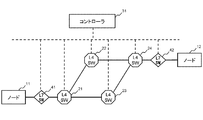
- the present invention includes a core network including lower layer switches (LLSWs 21A to 24A in FIG. 1) that perform packet transfer based on lower layer information, and an end of the core network. 1 and control devices (31A in FIG. 1) that control the upper layer switches (ULSWs 41A and 42A in FIG. 1), the lower layer switches (LLSWs 21A to 24A in FIG. 1), and the upper layer switches (ULSWs 41A and 42A in FIG. 1). ).
- LLSWs 21A to 24A in FIG. 1 that perform packet transfer based on lower layer information
- control devices 31A in FIG. 1 that control the upper layer switches (ULSWs 41A and 42A in FIG. 1), the lower layer switches (LLSWs 21A to 24A in FIG. 1), and the upper layer switches (ULSWs 41A and 42A in FIG. 1).
- the lower layer switches (LLSWs 21A to 24A in FIG. 1) hold control information in which match conditions including lower layer header information and processing contents are associated with each other, and match conditions that match the received packet.
- the received packet is transferred using the control information having
- the upper layer switches (ULSWs 41A and 42A in FIG. 1) rewrite a predetermined area of the header of the lower layer of the packet to the contents associated with the communication contents of the upper layer based on the header information of the upper layer.
- the control device (31A in FIG. 1) instructs the upper layer switch to rewrite the header area of the lower layer, and sets control information including the rewritten header information as a match condition to the lower layer switch. .
- control device (31A in FIG. 1) sends a predetermined area in the header of the lower layer of the packet to the upper layer switch (ULSW 41A, 42A in FIG. 1) based on the application type grasped from the header information of the upper layer.
- the control device (31A in FIG. 1) implements path control according to the application type by setting control information including the identifier as a match condition for the lower layer switches (LLSWs 21A to 24A in FIG. 1). Is done.
- the upper layer switch (ULSW 41A, 42A in FIG. 1) is directly connected to the external node (nodes 11A, 12A in FIG. 1), but the external node (nodes 11A, 12A in FIG. 1). ) And an upper layer switch (ULSW 41A, 42A in FIG. 1), a lower layer switch or the like may be arranged.
- two upper layer switches (ULSW 41A and 42A in FIG. 1) are arranged, but the upper layer switches (ULSW 41A and 42A in FIG. 1) will be described in the second and third embodiments described later. As such, one unit or three or more units may be arranged.
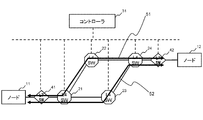
- FIG. 2 is a diagram illustrating the configuration of the communication system according to the first embodiment of this invention.
- layer 4 switches hereinafter referred to as “L4SW”) 21 to 24 that process packets in accordance with the flow entry set by the controller 31 are arranged at both ends (entrance and exit) of L4SWs 21 to 24.
- a configuration including a layer 7 switch (hereinafter referred to as “L7SW”) 41 and 42 and a controller 31 that controls these L4SW and L7SW is shown.
- the solid line indicates the connection relationship of the network that transmits data between the nodes 11 and 12, and the broken line indicates a control channel between the controller 31 and the L4SW and L7SW.
- Nodes 11 and 12 are user terminals and servers that communicate via the communication system described above.
- the controller 31 has a function equivalent to the open flow controller of Non-Patent Documents 1 and 2, and registers a flow entry (see FIG. 9) as control information in the L4SWs 21 to 24. Further, the controller 31 sets the header conversion tables shown in FIGS. 5 to 8 for the L7SWs 41 and 42, and controls the operation thereof.
- the L4SWs 21 to 24 request the controller 31 to set a flow entry (Packet-In). ).
- the L7SWs 41 and 42 identify the application being executed in the connected node from the layer 7 header of the received packet, and perform an operation of rewriting the L4 header with reference to the header conversion tables shown in FIGS. For example, when receiving the application A packet from the node 11, the L7SW 41 performs an operation of rewriting the L4 port number (60-1) of the node 11 to 61-1 with reference to the header conversion table shown in FIG.
- Such L7SWs 41 and 42 can be realized by a server having a function of relaying communication of nodes such as a proxy server and a reverse proxy server. Specific functions of the L7SWs 41 and 42 will be described later along with their operations.
- the controller 31 that has received the route selection policy registration from the user controls the L7SWs 41 and 42 as follows. First, the controller 31 determines a method for embedding route information in packets transmitted and received by the nodes 11 and 12.
- the method of embedding route information is any field below the L4 header referenced by the L2SWs 21 to 24.
- route information is embedded in the L4 port number on the node 11 side. That is, the route information is embedded in the source L4 port number for the packet addressed to the node 11 and the node 12, and the frame information addressed to the destination L4 port number for the frame addressed to the node 11 from the node 12.
- the controller 31 determines the L4 port number to be associated with the route.
- the mapping is determined in which the node 11 side L4 port number of the packet flowing through the path 51 is L4 port number 61 and the node 11 side L4 port number of the frame flowing through the path 52 is L4 port number 62. To do.
- the mapped port number is included in the match condition of the flow entry in the L4SWs 21 to 24 as a route selection key.
- the L4 port numbers 61 and 62 mapped to the paths 51 and 52 are rewritten to the L4 port number 60 by the L7SW 42, and are displayed as the L4 port number 60 from the node 12.
- L4 port number ranges 60, 61, and 62 are hereinafter referred to.
- L4 port number ranges 61 and 62 must not overlap.
- the L4 port number range 60 may be the same as the L4 port number range 61 or 62.
- the L4 port number ranges 60, 61, and 62 have the same width and are associated with respective port numbers. Assume that L4 port numbers 60-1, 61-1, and 62-1 are associated with each other in each L4 port number range.
- the mapping between the route used by the above application and the route selection key is as shown in FIG. 3, and is stored in the controller 31 as a route management table.
- the controller 31 notifies the L7SW 41 of a method for identifying the start of communication of the application A and the start of communication of the application B from the contents of the packet.
- the method for identifying the start of communication is based on information indicated by a tag of an HTTP protocol URL (Uniform Resource Locator) or XML (extensible Markup Language) content, for example.
- HTTP protocol URL Uniform Resource Locator
- XML extensible Markup Language
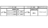
- the controller 31 corresponds to the L7SW 41 in the correspondence between the application A communication and the node 11 side L4 port number range 61 and the application B communication and the node 11 side L4 port number range 62 shown in FIG.
- Register the header conversion table also serves as a notification that the L4 port number ranges 61 and 62 should not be used for the node 11 side L4 port number in communications other than the applications A and B. If there is a possibility that the L4 port number range 61, 62 is used by the node 11, the action may be registered so that the L7SW 41 converts to another port number.
- the header conversion table may be applied only to communication between the node 11 and the node 12.
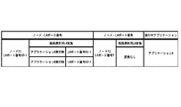
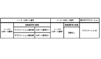
- the controller 31 registers a method for identifying the application from the packet in the L7SW 42 in the same manner as the L7SW41. Further, the controller 31 registers the header conversion table shown in FIG. 6 in which the L4 port number ranges 61 and 62 and the L4 port number range 60 are associated with each other in the L7SW 42. That is, the L4 port number ranges 61 and 62 on the node 11 side converted by the L7SW 41 are converted so that the node 12 can be seen as using the L4 port number range 60.
- the node 11 starts communication of the application A to the L4 port number Y of the node 12 using the L4 port number X.
- the packet of application A by the node 11 first reaches the L7SW 41.
- the L7SW 41 cannot identify the application until the three-way handshake is completed and the L7 data arrives. It is desirable to return (SYN-ACK packet).
- the three-way handshake itself may be treated as either application A or B and delivered to the node 12.
- the L7 port 41 refers to the header rewrite table shown in FIG. 5 and changes the L4 port number on the node 11 side to the port number 61-1 selected from the L4 port number range 61. Change and relay.
- the packet relayed from the L7SW 41 to the node 12 reaches the L4SW 21 next.
- the L4SW 21 searches for a flow entry having a matching condition corresponding to the packet.
- the L4SW 21 sends a message (Packet-In) that requests the controller 31 to set the flow entry with the packet attached. Send it out.
- the controller 31 Since the source L4 port number on the node 11 side is within the L4 port number range 61 in the header information included in the message (Packet-In), the controller 31 recognizes that the communication is for the application A. . From this recognition result, a flow entry is set for the L4SWs 21, 22, and 24 on the route 51 so that the corresponding packet flows on the route 51. At this time, the L4 port number range 61 is set as the L4 source port number in the flow entry match condition set in the L4SW 21 which is the branch point of the route.
- FIG. 9 is an example of a flow entry set in the L4SW 21. At this time, the entry 711 in FIG. 9 is set. In the above description, the flow entry is set after waiting for the message (Packet-In) from the L4SW 21. However, when the header rewrite table is set in the L7SW 41 and 42, the L4SW 21 to 24 are also set in advance. A flow entry may be set.
- the controller 31 sends the packet received from the L4SW 21 to the L4SW 24 and instructs to send it in the direction of the L7SW 42 (Packet-Out message).
- the L7SW 42 refers to the header rewriting table shown in FIG. 6, and the source L4 port number of the packet transferred from the L4SW 24 is the L4 port number 61-1, and is within the L4 port number range 61. Recognize that it is a communication packet. Then, the L7SW 42 refers to the header rewriting table shown in FIG. 6 and converts the source L4 port number into the L4 port number 60-1 that is a corresponding number in the L4 port number range 60 and relays it to the node 12.
- the packet that finally reaches the node 12 will appear to have arrived from the port number in the L4 port number range 60 of the node 11.
- the node 12 returns the packet of the application A to the node 11.
- the packet of the application A addressed to the node 12 and the node 11 that reaches the L7SW 42 has a destination port number of the L4 port number 60-1 and is within the range of the L4 port number range 60.
- the L7SW 42 confirms whether this packet is the application A or B according to the method registered from the controller 31. If the application cannot be identified, it is determined that the application stored at the previous relay is still being executed.
- the L7SW 42 stores that the application A was being executed at the time of the previous relay, determines that the communication of the application A is still continuing, and sets the destination L4 port number to the corresponding L4 port number 61- Rewrite to 1 and relay to L4SW24 direction.
- the controller 31 After reaching the L4SW 24, similarly to the packet transfer from the node 11 to the node 12, based on the message (Packet-In) from the L4SW 24, the controller 31 sets a flow entry for performing packet transfer along the path 51. Created and set to L4SW 24, 22, 21 on path 51. The controller 31 instructs the L4SW 21 to transfer a packet in the direction of the L7SW 41.
- the L7SW 41 recognizes that the communication of the application A is continuing because the destination port number of the received packet is the L4 port number 61-1.
- the L7SW 41 refers to the header rewriting table shown in FIG. 5 and rewrites the destination L4 port number to the port number (X) actually used by the node 11 and relays it to the node 11.
- the node 11 starts communication of the application B with the same port number (X).
- the L7SW 41 relays the application B packet from the node 11, it recognizes that the communication is the application B.
- L7SW 41 changes the application field being executed in the header rewriting table of FIG. 5 to “application B” as shown in FIG. Update.
- the L7SW 41 converts the L4 source port number of the packet of the application B into the port number 62-1 in the L4 port number range 62 with reference to the header rewriting table of FIG. 7, and relays it in the direction of the L4SW 21.
- TCP when TCP is used, it is necessary not to re-establish the TCP session but only to change the port number, and the sequence number of the TCP header needs to be numbered following the previous packet.
- the L4SW 21 that has received the packet sends a message (Packet-In) requesting setting of a flow entry with the packet attached thereto, as in the case of the application A.
- the controller 31 sets a flow entry for the application B in the L4SWs 21, 23, and 24 on the path 52. Further, the controller 31 sends the packet received from the L4SW 21 to the L4SW 24 and instructs to send it in the direction of the L7SW 42 (Packet-Out message).
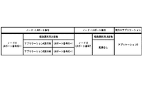
- the L7SW 42 recognizes the application B from the source L4 port number as in the case of the application A, and updates the executing application field of the header rewriting table of FIG. 6 to “application B” as shown in FIG. Further, the L7SW 42 refers to the header rewriting table of FIG. 8 and converts the L4 source port number of the packet of the application B into the port number 60-1 and relays it to the node 12.
- the source L4 port number after conversion is the same port number 60-1 as the port number used in the application A, the node 12 can be recognized as communication on the same TCP session.
- the function for identifying the application need only be installed in the L7SW corresponding to the edge of the network, the devices constituting the core network can concentrate on the transfer.
- the flow entry search function of the switch constituting the core network can be configured by ASIC (Application Specific Integrated Circuit), and high speed can be expected.
- the switches other than the branch point of the route selection may not be the OpenFlow switch.
- the L4SWs 22 and 23 can be replaced with L2 switches that learn MAC addresses and transfer packets.
- a node that does not need route control according to the application does not need to sandwich the L7SW when connecting to the network. It is possible to connect a node to which path control according to an application is applied and a node that does not need to be connected to the same network.
- a flow entry is set for each application. For this reason, it is applicable also to the use of measuring the traffic of an application by counting the packets that hit the flow entry using the flow statistics function of the OpenFlow switch.
- FIG. 10 is a diagram showing the configuration of the second exemplary embodiment of the present invention.
- FIG. 10 shows a configuration in which the L7SW 42 is removed from the configuration of the first embodiment of FIG. 2 and the node 12 is connected to the L4SW 24.
- FIG. 11 is a configuration in which the L7SW 41 is removed from the configuration of the first embodiment of FIG. 2 and the node 11 is connected to the L4SW 21.
- the operation of the L7SW converting the L4 port number according to the application of the frame received from the node and sending it to the L4SW is the same.
- the source L4 port number converted by the L7SW for route selection is converted by the opposite L7SW and shown as one L4 port number.
- the L7SW is on the exit side. Since it is not deployed, this must be done at the L4 switch at the exit of the network.
- This operation can be realized by setting a flow entry that causes the L4SW to rewrite the header. Specifically, in the configuration of FIG. 10, a flow entry for further rewriting the L4 port number of the packet rewritten by the L7SW 41 is set in the L4SW 24. Similarly, in the configuration of FIG. 11, a similar flow entry is set in the L4SW 21.
- the packet addressed to the node 12 and the node 11 in FIG. 10 and the frame addressed to the node 11 and the node 12 in FIG. 11 will be described.
- the path of the frame in this direction is determined by the controller 31, and a flow entry for delivery to the L7SW must be registered in each L4SW.
- the L7SW when a packet arrives from the L4SW to the L7SW, the L7SW refers to the L4 port number and detects that the application has been switched in the opposite node. Then this operation is not performed.
- FIG. 12 is a diagram showing the configuration of a communication system according to the third embodiment of the present invention.
- the configuration of FIG. 12 is similar to that of FIG. 10, but the operation of the L7SW 43 is different.
- the operation will be described assuming that the node 13 is an HTTP client and the node 14 is an HTTP server.
- communication of application C uses path 53 of FIG. 13 through L4SW 26
- communication of application D uses path 54 of FIG. 13 through L4 switch 27.
- the user registers this route selection policy in the controller 32.
- the controller 32 that has received the route selection policy registration from the user controls the L7SW 43 as follows. First, the controller 32 registers a method for identifying the start of communication of the application C and the start of communication of the application D from the contents of the packet in the L7SW 43. In the case of HTTP, an application can be identified from the content of a request such as a URL.
- controller 32 registers, in the L7SW 43, a header conversion table with an action for proxy connection with a source L4 port number in a specific range as an action when the communication start of the application C or the application D is detected.
- FIG. 14 is an example of a header conversion table registered in the L7SW43.
- the range of the source L4 port number at the proxy connection of the application C is the L4 port number range 63
- the range of the source L4 port number at the proxy connection of the application D is the L4 port number range 64.
- This registration of the header conversion table also serves as an instruction that the L4 port number range 63 as the source L4 port number for the L7SW 43 and the L4 port number range 64 should not be used for communications other than the applications C and D.
- the packet transmitted by the node 13 first reaches the L7SW 43.
- the L7SW 43 analyzes this packet, recognizes that the node 13 has started communication of the application C, and addresses the node 14 as the L4 port 63-1 selected from the L4 port range 63 according to the entry 721 in FIG. Connect as a proxy.
- the controller 32 sets a flow entry for transferring the packet transmitted by the L7SW 43 connected to the node 14 by proxy connection to the L4SWs 25, 26, and 28 on the path 53.
- a condition that the L4 port on the L7SW 43 side is within the L4 port range 63 is set as a match condition.
- the packet of the application C transmitted by the L7SW 43 connected by proxy to the node 14 is transferred to the node 14.
- the node 14 will recognize it as a connection from the source L4 port 63-1.
- the controller 32 sets a flow entry for transferring the packet transmitted by the L7SW 43 connected to the node 14 by proxy connection to the L4SWs 25, 27, and 28 on the path 54.
- a condition that the L4 port on the L7SW 43 side is within the L4 port range 64 is set as a match condition.
- the packet of the application D transmitted by the L7SW 43 connected by proxy to the node 14 is transferred to the node 14.
- the node 14 will recognize it as a connection from the source L4 port 64-2.
- the L4SW is used as the lower layer switch.
- any device that can operate as an open flow switch may be used.
- a communication system including a second upper layer switch that is arranged at another end of the core network and rewrites the lower layer header area rewritten by the upper layer switch to a predetermined content indicating a transmission source.
- the second upper layer switch associates a predetermined area of the lower layer header of the packet with the communication content of the upper layer for a packet received from the reverse direction based on an instruction from the control device.
- the communication system in which the upper layer switch restores the lower layer header area rewritten by the second upper layer switch.
- the upper layer switch detects occurrence of specific communication between external nodes, the upper layer switch connects to the lower layer switch as a proxy, The communication system in which the control device sets control information having a matching condition for identifying a packet from the proxy-connected higher layer switch in the lower layer switch.
- the control device sets control information having a matching condition for identifying a packet from the proxy-connected higher layer switch in the lower layer switch.
- the communication system in which the upper layer switch or the second upper layer switch rewrites a header of a lower layer based on a header rewrite table set by the control device.
- the upper layer switch is a layer 7 switch for identifying an application
- the control device is a communication system that performs path control according to an application type.
- the upper layer switch is a layer 7 switch for identifying an application
- the communication system instructs the upper layer switch or the second upper layer switch to convert a layer 4 port number of a received packet into a number range associated with an application type.
- the lower layer switch is an open flow switch
- the communication system is an open flow controller in which the control device sets a flow entry including a layer 4 port number range as a match condition as the control information.
Landscapes
- Engineering & Computer Science (AREA)
- Computer Networks & Wireless Communication (AREA)
- Signal Processing (AREA)
- Computer Security & Cryptography (AREA)
- Data Exchanges In Wide-Area Networks (AREA)
Abstract
Description
本発明は、日本国特許出願:特願2012-074654号(2012年3月28日出願)に基づくものであり、同出願の全記載内容は引用をもって本書に組み込み記載されているものとする。
本発明は、通信システム、上位レイヤスイッチ、制御装置、スイッチ制御方法及びプログラムに関し、特に、制御装置から設定された制御情報に従って動作するスイッチを含む通信システム、上位レイヤスイッチ、制御装置、スイッチ制御方法及びプログラムに関する。 [Description of related applications]
The present invention is based on a Japanese patent application: Japanese Patent Application No. 2012-074654 (filed on Mar. 28, 2012), and the entire description of the application is incorporated herein by reference.
The present invention relates to a communication system, an upper layer switch, a control device, a switch control method, and a program, and in particular, a communication system including a switch that operates according to control information set from the control device, an upper layer switch, a control device, and a switch control method. And the program.
続いて、本発明の第1の実施形態について図面を参照して詳細に説明する。図2は、本発明の第1の実施形態の通信システムの構成を示す図である。図2を参照すると、コントローラ31から設定されるフローエントリに従ってパケットを処理するレイヤ4スイッチ(以下、「L4SW」と記す。)21~24と、L4SW21~24の両端(入口と出口)に配置されるレイヤ7スイッチ(以下、「L7SW」と記す。)41、42と、これらL4SWおよびL7SWを制御するコントローラ31とを含む構成が示されている。なお、図2において、実線は、ノード11、12間のデータを伝送するネットワークの接続関係を示し、破線は、コントローラ31とL4SWおよびL7SW間の制御用のチャネルを表している。 [First Embodiment]
Next, a first embodiment of the present invention will be described in detail with reference to the drawings. FIG. 2 is a diagram illustrating the configuration of the communication system according to the first embodiment of this invention. Referring to FIG. 2, layer 4 switches (hereinafter referred to as “L4SW”) 21 to 24 that process packets in accordance with the flow entry set by the
続いて、コアネットワークの両端ではなく、その一端にL7SWを配置するようにした本発明の第2の実施形態について図面を参照して詳細に説明する。図10、図11は、本発明の第2の実施形態に係る通信システムの構成を表した図である。以下、第1の実施形態との相違点を中心に説明する。 [Second Embodiment]
Next, a second embodiment of the present invention in which L7SW is arranged at one end of the core network instead of at both ends will be described in detail with reference to the drawings. 10 and 11 are diagrams showing the configuration of a communication system according to the second embodiment of the present invention. Hereinafter, a description will be given focusing on differences from the first embodiment.
図10に示した第2の実施形態と同様の構成でも特定のアプリケーションについては両方向の通信についてアプリケーションに応じた経路制御ができる。このような特定のアプリケーションによる通信がおこなわれることを前提した本発明の第3の実施形態について説明する。 [Third Embodiment]
Even in the same configuration as that of the second embodiment shown in FIG. 10, for a specific application, path control according to the application can be performed for bidirectional communication. A third embodiment of the present invention on the premise that communication by such a specific application is performed will be described.
[第1の形態]
(上記第1の視点による通信システム参照)
[第2の形態]
第1の形態の通信システムにおいて、さらに、
前記コアネットワークの別の一端に配置され、前記上位レイヤスイッチにより書き換えられた前記下位レイヤのヘッダ領域を、送信元を示す所定の内容に書き換える第2の上位レイヤスイッチを含む通信システム。
[第3の形態]
第2の形態の通信システムにおいて、
前記第2の上位レイヤスイッチは、前記制御装置からの指示に基づいて逆方向から受信したパケットに対し、前記パケットの下位レイヤのヘッダの所定領域を、前記上位レイヤの通信内容に対応付けられた内容に書き換える動作を行い、
前記上位レイヤスイッチは、前記第2の上位レイヤスイッチにより書き換えられた前記下位レイヤのヘッダ領域を復元する通信システム。
[第4の形態]
第1から第3いずれか一の形態の通信システムにおいて、
前記上位レイヤスイッチは、外部ノード間で特定の通信の発生を検出すると、前記下位レイヤスイッチに代理接続し、
前記制御装置は、前記下位レイヤスイッチに、前記代理接続した前記上位レイヤスイッチからのパケットを識別するマッチ条件を持つ制御情報を設定する通信システム。
[第5の形態]
第1から第4いずれか一の形態の通信システムにおいて、
前記上位レイヤスイッチまたは前記第2の上位レイヤスイッチは、前記制御装置から設定されたヘッダ書き換えテーブルに基づいて、下位レイヤのヘッダの書き換えを行う通信システム。
[第6の形態]
第1から第5いずれか一の形態の通信システムにおいて、
前記上位レイヤスイッチは、アプリケーションを識別するレイヤ7スイッチであり、
前記制御装置は、アプリケーション種別に応じた経路制御を行う通信システム。
[第7の形態]
第1から第6いずれか一の形態の通信システムにおいて、
前記上位レイヤスイッチは、アプリケーションを識別するレイヤ7スイッチであり、
前記制御装置は、前記上位レイヤスイッチまたは前記第2の上位レイヤスイッチに対して、受信パケットのレイヤ4ポート番号を、アプリケーション種別に対応付けた番号範囲に変換するよう指示する通信システム。
[第8の形態]
第1から第7いずれか一の形態の通信システムにおいて、
前記下位レイヤスイッチは、オープンフロースイッチであり、
前記制御装置は、前記制御情報として、レイヤ4ポート番号範囲をマッチ条件に含むフローエントリを設定するオープンフローコントローラである通信システム。
[第9の形態]
(上記第2の視点による上位レイヤスイッチ参照)
[第10の形態]
(上記第3の視点による制御装置参照)
[第11の形態]
(上記第4の視点によるスイッチ制御方法参照)
[第12の形態]
(上記第5の視点によるプログラム参照)
なお、上記第9~第12の形態は、第1の形態と同様に、第2~第8の形態に展開することが可能である。 Finally, a preferred form of the invention is summarized.
[First embodiment]
(Refer to the communication system according to the first viewpoint)
[Second form]
In the communication system of the first form,
A communication system including a second upper layer switch that is arranged at another end of the core network and rewrites the lower layer header area rewritten by the upper layer switch to a predetermined content indicating a transmission source.
[Third embodiment]
In the communication system of the second form,
The second upper layer switch associates a predetermined area of the lower layer header of the packet with the communication content of the upper layer for a packet received from the reverse direction based on an instruction from the control device. Perform the operation to rewrite the contents,
The communication system in which the upper layer switch restores the lower layer header area rewritten by the second upper layer switch.
[Fourth form]
In the communication system according to any one of the first to third aspects,
When the upper layer switch detects occurrence of specific communication between external nodes, the upper layer switch connects to the lower layer switch as a proxy,
The communication system in which the control device sets control information having a matching condition for identifying a packet from the proxy-connected higher layer switch in the lower layer switch.
[Fifth embodiment]
In the communication system according to any one of the first to fourth aspects,
The communication system in which the upper layer switch or the second upper layer switch rewrites a header of a lower layer based on a header rewrite table set by the control device.
[Sixth embodiment]
In the communication system according to any one of the first to fifth aspects,
The upper layer switch is a layer 7 switch for identifying an application,
The control device is a communication system that performs path control according to an application type.
[Seventh form]
In the communication system according to any one of the first to sixth aspects,
The upper layer switch is a layer 7 switch for identifying an application,
The communication system instructs the upper layer switch or the second upper layer switch to convert a layer 4 port number of a received packet into a number range associated with an application type.
[Eighth form]
In the communication system according to any one of the first to seventh aspects,
The lower layer switch is an open flow switch,
The communication system is an open flow controller in which the control device sets a flow entry including a layer 4 port number range as a match condition as the control information.
[Ninth Embodiment]
(See upper layer switch from the second perspective above)
[Tenth embodiment]
(Refer to the control device from the third viewpoint)
[Eleventh form]
(See the switch control method from the fourth viewpoint above)
[Twelfth embodiment]
(Refer to the program from the fifth viewpoint above)
Note that the ninth to twelfth forms can be developed into the second to eighth forms as in the first form.
21~28 レイヤ4スイッチ(L4SW)
21A~24A 下位レイヤスイッチ(LLSW)
31、32 コントローラ
31A 制御装置
41~43 レイヤ7スイッチ(L7SW)
41A、42A 上位レイヤスイッチ(ULSW)
51~54 経路
711~714 フローエントリ
721、722 エントリ 11-14, 11A, 12A Node 21-28 Layer 4 switch (L4SW)
21A-24A Lower layer switch (LLSW)
31, 32
41A, 42A Upper layer switch (ULSW)
51-54 Route 711-714 Flow entry 721, 722 entry
Claims (12)
- 下位レイヤのヘッダ情報を含むマッチ条件と、処理内容とを対応付けた制御情報を保持し、受信パケットに適合するマッチ条件を持つ制御情報を用いて受信パケットを処理する下位レイヤスイッチを含んだコアネットワークと、
前記コアネットワークの端部に配置され、パケットの下位レイヤのヘッダの所定領域を、上位レイヤの通信内容に対応付けられた内容に書き換える上位レイヤスイッチと、
前記上位レイヤスイッチに対し前記下位レイヤのヘッダ領域の書き換えを指示するとともに、前記下位レイヤスイッチに前記書き換え後のヘッダ情報をマッチ条件に含む制御情報を設定する制御装置と、
を含む通信システム。 Core that includes lower layer switches that hold control information that associates processing conditions with match conditions including lower layer header information and that process received packets using control information that has matching conditions that match the received packets Network,
An upper layer switch that is disposed at an end of the core network and rewrites a predetermined area of a lower layer header of a packet to contents associated with communication contents of an upper layer;
A control device that instructs the upper layer switch to rewrite the header layer of the lower layer, and sets control information including the header information after rewriting in the lower layer switch as a match condition;
A communication system including: - 前記コアネットワークの別の一端に配置され、前記上位レイヤスイッチにより書き換えられた前記下位レイヤのヘッダ領域を、送信元を示す所定の内容に書き換える第2の上位レイヤスイッチを含む請求項1の通信システム。 2. The communication system according to claim 1, further comprising: a second upper layer switch that is arranged at another end of the core network and rewrites the lower layer header area rewritten by the upper layer switch to a predetermined content indicating a transmission source. .
- 前記第2の上位レイヤスイッチは、前記制御装置からの指示に基づいて逆方向から受信したパケットに対し、前記パケットの下位レイヤのヘッダの所定領域を、前記上位レイヤの通信内容に対応付けられた内容に書き換える動作を行い、
前記上位レイヤスイッチは、前記第2の上位レイヤスイッチにより書き換えられた前記下位レイヤのヘッダ領域を復元する請求項2の通信システム。 The second upper layer switch associates a predetermined area of the lower layer header of the packet with the communication content of the upper layer for a packet received from the reverse direction based on an instruction from the control device. Perform the operation to rewrite the contents,
The communication system according to claim 2, wherein the upper layer switch restores the header area of the lower layer rewritten by the second upper layer switch. - 前記上位レイヤスイッチは、外部ノード間で特定の通信の発生を検出すると、前記下位レイヤスイッチに代理接続し、
前記制御装置は、前記下位レイヤスイッチに、前記代理接続した前記上位レイヤスイッチからのパケットを識別するマッチ条件を持つ制御情報を設定する請求項1から3いずれか一の通信システム。 When the upper layer switch detects the occurrence of a specific communication between external nodes, it connects to the lower layer switch as a proxy,
The communication system according to any one of claims 1 to 3, wherein the control device sets control information having a matching condition for identifying a packet from the proxy-connected higher layer switch in the lower layer switch. - 前記上位レイヤスイッチまたは前記第2の上位レイヤスイッチは、前記制御装置から設定されたヘッダ書き換えテーブルに基づいて、下位レイヤのヘッダの書き換えを行う請求項1から4いずれか一の通信システム。 The communication system according to any one of claims 1 to 4, wherein the upper layer switch or the second upper layer switch rewrites a lower layer header based on a header rewrite table set by the control device.
- 前記上位レイヤスイッチは、アプリケーションを識別するレイヤ7スイッチであり、
前記制御装置は、アプリケーション種別に応じた経路制御を行う請求項1から5いずれか一の通信システム。 The upper layer switch is a layer 7 switch for identifying an application,
The communication system according to claim 1, wherein the control device performs path control according to an application type. - 前記上位レイヤスイッチは、アプリケーションを識別するレイヤ7スイッチであり、
前記制御装置は、前記上位レイヤスイッチまたは前記第2の上位レイヤスイッチに対して、受信パケットのレイヤ4ポート番号を、アプリケーション種別に対応付けた番号範囲に変換するよう指示する請求項1から6いずれか一の通信システム。 The upper layer switch is a layer 7 switch for identifying an application,
The control device instructs the upper layer switch or the second upper layer switch to convert the layer 4 port number of the received packet into a number range associated with the application type. One communication system. - 前記下位レイヤスイッチは、オープンフロースイッチであり、
前記制御装置は、前記制御情報として、レイヤ4ポート番号範囲をマッチ条件に含むフローエントリを設定するオープンフローコントローラである請求項1から7いずれか一の通信システム。 The lower layer switch is an open flow switch,
The communication system according to any one of claims 1 to 7, wherein the control device is an open flow controller that sets a flow entry including a layer 4 port number range as a match condition as the control information. - 下位レイヤのヘッダ情報を含むマッチ条件と、処理内容とを対応付けた制御情報を保持し、受信パケットに適合するマッチ条件を持つ制御情報を用いて受信パケットを処理する下位レイヤスイッチを含んだコアネットワークの端部に配置され、
所定の制御装置からの指示に基づいて、パケットの下位レイヤのヘッダの所定領域を、上位レイヤの通信内容に対応付けられた内容に書き換える上位レイヤスイッチ。 Core that includes lower layer switches that hold control information that associates processing conditions with match conditions including lower layer header information and that process received packets using control information that has matching conditions that match the received packets Located at the end of the network,
An upper layer switch that rewrites a predetermined area of a lower layer header of a packet to contents associated with communication contents of an upper layer based on an instruction from a predetermined control device. - 下位レイヤのヘッダ情報を含むマッチ条件と、処理内容とを対応付けた制御情報を保持し、受信パケットに適合するマッチ条件を持つ制御情報を用いて受信パケットを処理する下位レイヤスイッチを含んだコアネットワークと、
前記コアネットワークの端部に配置され、パケットの下位レイヤのヘッダの所定領域を、上位レイヤの通信内容に対応付けられた内容に書き換える上位レイヤスイッチと、に接続され、
前記上位レイヤスイッチに対し前記下位レイヤのヘッダ領域の書き換えを指示するとともに、前記下位レイヤスイッチに前記書き換え後のヘッダ情報をマッチ条件に含む制御情報を設定する制御装置。 Core containing a lower layer switch that holds control information that associates processing conditions with match conditions including lower layer header information and processes received packets using control information that has matching conditions that match the received packets Network,
An upper layer switch that is disposed at an end of the core network and rewrites a predetermined area of a lower layer header of a packet to contents associated with communication contents of an upper layer,
A control device that instructs the upper layer switch to rewrite the header region of the lower layer, and sets control information including the rewritten header information as a match condition in the lower layer switch. - 下位レイヤのヘッダ情報を含むマッチ条件と、処理内容とを対応付けた制御情報を保持し、受信パケットに適合するマッチ条件を持つ制御情報を用いて受信パケットを処理する下位レイヤスイッチを含んだコアネットワークと、
前記コアネットワークの端部に配置され、パケットの下位レイヤのヘッダの所定領域を、上位レイヤの通信内容に対応付けられた内容に書き換える上位レイヤスイッチと、を含むネットワークにおいて、
前記上位レイヤスイッチに対し前記下位レイヤのヘッダ領域の書き換えを指示するステップと、
前記下位レイヤスイッチに、前記書き換え後のヘッダ情報をマッチ条件に含む制御情報を設定するステップと、を含むスイッチ制御方法。 Core that includes lower layer switches that hold control information that associates processing conditions with match conditions including lower layer header information and that process received packets using control information that has matching conditions that match the received packets Network,
In a network including an upper layer switch that is arranged at an end of the core network and rewrites a predetermined area of a lower layer header of a packet to contents associated with communication contents of an upper layer,
Instructing the upper layer switch to rewrite the header area of the lower layer;
Setting control information including the rewritten header information as a match condition in the lower layer switch. - 下位レイヤのヘッダ情報を含むマッチ条件と、処理内容とを対応付けた制御情報を保持し、受信パケットに適合するマッチ条件を持つ制御情報を用いて受信パケットを処理する下位レイヤスイッチを含んだコアネットワークと、
前記コアネットワークの端部に配置され、パケットの下位レイヤのヘッダの所定領域を、上位レイヤの通信内容に対応付けられた内容に書き換える上位レイヤスイッチと、を含むネットワークに接続されたコンピュータに、
前記上位レイヤスイッチに対し前記下位レイヤのヘッダ領域の書き換えを指示する処理と、
前記下位レイヤスイッチに、前記書き換え後のヘッダ情報をマッチ条件に含む制御情報を設定する処理と、を実行させるプログラム。 Core containing a lower layer switch that holds control information that associates processing conditions with match conditions including lower layer header information and processes received packets using control information that has matching conditions that match the received packets Network,
To a computer connected to a network, which is arranged at an end of the core network and includes a higher layer switch that rewrites a predetermined area of a lower layer header of a packet to contents associated with communication contents of an upper layer,
Processing to instruct the upper layer switch to rewrite the header area of the lower layer;
A program for causing the lower layer switch to execute a process of setting control information including the rewritten header information as a match condition.
Priority Applications (4)
| Application Number | Priority Date | Filing Date | Title |
|---|---|---|---|
| JP2014507958A JP5858147B2 (en) | 2012-03-28 | 2013-03-27 | COMMUNICATION SYSTEM, UPPER LAYER SWITCH, CONTROL DEVICE, SWITCH CONTROL METHOD, AND PROGRAM |
| CN201380017101.3A CN104205749B (en) | 2012-03-28 | 2013-03-27 | A kind of communication system, Upper Switch, control device and Switch control method |
| US14/388,206 US9515926B2 (en) | 2012-03-28 | 2013-03-27 | Communication system, upper layer switch, control apparatus, switch control method, and program |
| EP13768798.4A EP2833585B1 (en) | 2012-03-28 | 2013-03-27 | Communication system, upper layer switch, control device, switch control method, and program |
Applications Claiming Priority (2)
| Application Number | Priority Date | Filing Date | Title |
|---|---|---|---|
| JP2012074654 | 2012-03-28 | ||
| JP2012-074654 | 2012-03-28 |
Publications (1)
| Publication Number | Publication Date |
|---|---|
| WO2013146885A1 true WO2013146885A1 (en) | 2013-10-03 |
Family
ID=49260134
Family Applications (1)
| Application Number | Title | Priority Date | Filing Date |
|---|---|---|---|
| PCT/JP2013/059008 WO2013146885A1 (en) | 2012-03-28 | 2013-03-27 | Communication system, upper layer switch, control device, switch control method, and program |
Country Status (5)
| Country | Link |
|---|---|
| US (1) | US9515926B2 (en) |
| EP (1) | EP2833585B1 (en) |
| JP (1) | JP5858147B2 (en) |
| CN (1) | CN104205749B (en) |
| WO (1) | WO2013146885A1 (en) |
Cited By (2)
| Publication number | Priority date | Publication date | Assignee | Title |
|---|---|---|---|---|
| JP2017017477A (en) * | 2015-06-30 | 2017-01-19 | 富士通株式会社 | Communication device, communication method and communication program |
| JP2021500802A (en) * | 2017-10-23 | 2021-01-07 | サイトリックス システムズ,インコーポレイテッド | Systems and methods for first packet application classification |
Families Citing this family (7)
| Publication number | Priority date | Publication date | Assignee | Title |
|---|---|---|---|---|
| TWI543566B (en) | 2015-05-12 | 2016-07-21 | 財團法人工業技術研究院 | Data center network system based on software-defined network and packet forwarding method, address resolution method, routing controller thereof |
| CN106357483B (en) | 2015-07-17 | 2021-06-01 | 华为技术有限公司 | Message transmission method, access node, access controller and access system |
| CN108886495B (en) * | 2016-02-18 | 2022-07-05 | 瑞萨电子株式会社 | Message processor |
| TWI636679B (en) | 2017-02-07 | 2018-09-21 | 財團法人工業技術研究院 | Virtual local area network configuration system and method, and computer program product thereof |
| US20230021019A1 (en) * | 2021-07-16 | 2023-01-19 | Vmware, Inc. | Managing l4 ports |
| US20230013489A1 (en) * | 2021-07-16 | 2023-01-19 | Vmware, Inc. | Managing l4 ports |
| US20230015075A1 (en) * | 2021-07-16 | 2023-01-19 | Vmware, Inc. | Managing l4 ports |
Citations (8)
| Publication number | Priority date | Publication date | Assignee | Title |
|---|---|---|---|---|
| JP2002261792A (en) * | 2000-12-28 | 2002-09-13 | Nec Corp | Communication system, its packet exchanging method, and recording medium with exchange program recorded thereon |
| JP2004228791A (en) * | 2003-01-21 | 2004-08-12 | Hitachi Communication Technologies Ltd | Bulk communication controller |
| JP2005109536A (en) * | 2003-09-26 | 2005-04-21 | Nippon Telegr & Teleph Corp <Ntt> | Method and system for controlling application flow |
| JP2006174374A (en) * | 2004-12-20 | 2006-06-29 | Fujitsu Ltd | Relay system |
| JP2006203904A (en) | 2005-01-21 | 2006-08-03 | Nec Corp | Method, content based router, and content based network |
| WO2008095010A1 (en) | 2007-02-01 | 2008-08-07 | The Board Of Trustees Of The Leland Stanford Jr. University | Secure network switching infrastructure |
| WO2011037105A1 (en) * | 2009-09-25 | 2011-03-31 | 日本電気株式会社 | Content-based switching system and content-based switching method |
| JP2012186649A (en) * | 2011-03-04 | 2012-09-27 | Nec Corp | Communication switching system, communication switching method, and program |
Family Cites Families (5)
| Publication number | Priority date | Publication date | Assignee | Title |
|---|---|---|---|---|
| US7519048B2 (en) | 2000-12-28 | 2009-04-14 | Nec Corporation | Communication system and packet switching method thereof |
| US7616563B1 (en) * | 2005-08-31 | 2009-11-10 | Chelsio Communications, Inc. | Method to implement an L4-L7 switch using split connections and an offloading NIC |
| EP2416532B1 (en) | 2009-03-30 | 2014-10-08 | Nec Corporation | Communication flow control system, communication flow control method, and communication flow processing program |
| JP5382451B2 (en) | 2010-01-29 | 2014-01-08 | 日本電気株式会社 | Front-end system, front-end processing method |
| EP2572473B1 (en) * | 2010-05-19 | 2014-02-26 | Telefonaktiebolaget L M Ericsson (PUBL) | Methods and apparatus for use in an openflow network |
-
2013
- 2013-03-27 US US14/388,206 patent/US9515926B2/en active Active
- 2013-03-27 JP JP2014507958A patent/JP5858147B2/en not_active Expired - Fee Related
- 2013-03-27 WO PCT/JP2013/059008 patent/WO2013146885A1/en active Application Filing
- 2013-03-27 EP EP13768798.4A patent/EP2833585B1/en not_active Not-in-force
- 2013-03-27 CN CN201380017101.3A patent/CN104205749B/en not_active Expired - Fee Related
Patent Citations (8)
| Publication number | Priority date | Publication date | Assignee | Title |
|---|---|---|---|---|
| JP2002261792A (en) * | 2000-12-28 | 2002-09-13 | Nec Corp | Communication system, its packet exchanging method, and recording medium with exchange program recorded thereon |
| JP2004228791A (en) * | 2003-01-21 | 2004-08-12 | Hitachi Communication Technologies Ltd | Bulk communication controller |
| JP2005109536A (en) * | 2003-09-26 | 2005-04-21 | Nippon Telegr & Teleph Corp <Ntt> | Method and system for controlling application flow |
| JP2006174374A (en) * | 2004-12-20 | 2006-06-29 | Fujitsu Ltd | Relay system |
| JP2006203904A (en) | 2005-01-21 | 2006-08-03 | Nec Corp | Method, content based router, and content based network |
| WO2008095010A1 (en) | 2007-02-01 | 2008-08-07 | The Board Of Trustees Of The Leland Stanford Jr. University | Secure network switching infrastructure |
| WO2011037105A1 (en) * | 2009-09-25 | 2011-03-31 | 日本電気株式会社 | Content-based switching system and content-based switching method |
| JP2012186649A (en) * | 2011-03-04 | 2012-09-27 | Nec Corp | Communication switching system, communication switching method, and program |
Non-Patent Citations (3)
| Title |
|---|
| NICK MCKEOWN, OPENFLOW: ENABLING INNOVATION IN CAMPUS NETWORKS, 14 February 2012 (2012-02-14), Retrieved from the Internet <URL:http://www.openflow.org/documents/openflow-wp-latest.pdf>> |
| OPENFLOW SWITCH SPECIFICATION, 14 February 2012 (2012-02-14), Retrieved from the Internet <URL:http:J/www.openflow.orgldocumentslopenflow-spec-vl.l.0.pdf >> |
| See also references of EP2833585A4 |
Cited By (4)
| Publication number | Priority date | Publication date | Assignee | Title |
|---|---|---|---|---|
| JP2017017477A (en) * | 2015-06-30 | 2017-01-19 | 富士通株式会社 | Communication device, communication method and communication program |
| JP2021500802A (en) * | 2017-10-23 | 2021-01-07 | サイトリックス システムズ,インコーポレイテッド | Systems and methods for first packet application classification |
| US11095562B2 (en) | 2017-10-23 | 2021-08-17 | Citrix Systems, Inc. | Systems and methods for first packet application classification |
| JP7026219B2 (en) | 2017-10-23 | 2022-02-25 | サイトリックス システムズ,インコーポレイテッド | Systems and methods for first packet application classification |
Also Published As
| Publication number | Publication date |
|---|---|
| JPWO2013146885A1 (en) | 2015-12-14 |
| EP2833585B1 (en) | 2017-03-08 |
| CN104205749A (en) | 2014-12-10 |
| US9515926B2 (en) | 2016-12-06 |
| EP2833585A4 (en) | 2015-10-21 |
| EP2833585A1 (en) | 2015-02-04 |
| CN104205749B (en) | 2017-04-05 |
| JP5858147B2 (en) | 2016-02-10 |
| US20150043588A1 (en) | 2015-02-12 |
Similar Documents
| Publication | Publication Date | Title |
|---|---|---|
| JP5858147B2 (en) | COMMUNICATION SYSTEM, UPPER LAYER SWITCH, CONTROL DEVICE, SWITCH CONTROL METHOD, AND PROGRAM | |
| JP5382451B2 (en) | Front-end system, front-end processing method | |
| US9215175B2 (en) | Computer system including controller and plurality of switches and communication method in computer system | |
| JP5994851B2 (en) | Transfer device control device, transfer device control method, communication system, and program | |
| WO2012090996A1 (en) | Information system, control device, virtual network provision method and program | |
| WO2011087085A1 (en) | Calculator, network connection switching method, and program | |
| WO2014133015A1 (en) | Control apparatus, communication system, switch control method and program | |
| WO2017209923A1 (en) | Detecting source network address translation in a communication system | |
| JP5858141B2 (en) | Control device, communication device, communication system, communication method, and program | |
| US11652739B2 (en) | Service related routing method and apparatus | |
| JP5987971B2 (en) | Communication system, switch, control device, control channel construction method and program | |
| WO2013147193A1 (en) | Network appliance redundancy system, control device, network appliance redundancy method and program | |
| WO2014129624A1 (en) | Control device, communication system, path switching method, and program | |
| WO2014175423A1 (en) | Communication node, communication system, packet processing method and program | |
| WO2014069502A1 (en) | Communication system, path information exchange device, communication node, transfer method for path information and program | |
| WO2013062070A1 (en) | Control apparatus, communication system, virtual network management method, and program | |
| JP6206493B2 (en) | CONTROL DEVICE, COMMUNICATION SYSTEM, RELAY DEVICE CONTROL METHOD, AND PROGRAM | |
| JP6024761B2 (en) | Control device, communication system, communication method, and program | |
| JP6128132B2 (en) | COMMUNICATION DEVICE, CONTROL DEVICE, COMMUNICATION SYSTEM, PACKET PROCESSING METHOD, COMMUNICATION DEVICE CONTROL METHOD, AND PROGRAM | |
| WO2014119602A1 (en) | Control apparatus, switch, communication system, switch control method and program | |
| JP6160101B2 (en) | Communication device, control device, communication system, and control message transmission method | |
| WO2014142081A1 (en) | Transfer node, control device, communication system, packet processing method and program | |
| WO2014087993A1 (en) | Control apparatus, communication system, communication method and program | |
| JP2014212398A (en) | Communication system, communication node, packet processing method, and program | |
| JP2016225933A (en) | Control device, control method for relay device, program, and communication system |
Legal Events
| Date | Code | Title | Description |
|---|---|---|---|
| 121 | Ep: the epo has been informed by wipo that ep was designated in this application |
Ref document number: 13768798 Country of ref document: EP Kind code of ref document: A1 |
|
| WWE | Wipo information: entry into national phase |
Ref document number: 14388206 Country of ref document: US |
|
| ENP | Entry into the national phase |
Ref document number: 2014507958 Country of ref document: JP Kind code of ref document: A |
|
| NENP | Non-entry into the national phase |
Ref country code: DE |
|
| REEP | Request for entry into the european phase |
Ref document number: 2013768798 Country of ref document: EP |
|
| WWE | Wipo information: entry into national phase |
Ref document number: 2013768798 Country of ref document: EP |