WO2013146249A1 - 等電点の測定方法、ならびにそのためのセンサーチップ、測定装置、測定システムおよびプログラム - Google Patents
等電点の測定方法、ならびにそのためのセンサーチップ、測定装置、測定システムおよびプログラム Download PDFInfo
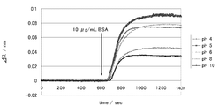
- Publication number
- WO2013146249A1 WO2013146249A1 PCT/JP2013/056943 JP2013056943W WO2013146249A1 WO 2013146249 A1 WO2013146249 A1 WO 2013146249A1 JP 2013056943 W JP2013056943 W JP 2013056943W WO 2013146249 A1 WO2013146249 A1 WO 2013146249A1
- Authority
- WO
- WIPO (PCT)
- Prior art keywords
- substance
- isoelectric point
- measurement
- data
- sensor chip
- Prior art date
- Legal status (The legal status is an assumption and is not a legal conclusion. Google has not performed a legal analysis and makes no representation as to the accuracy of the status listed.)
- Ceased
Links
Images



Classifications
-
- G—PHYSICS
- G01—MEASURING; TESTING
- G01N—INVESTIGATING OR ANALYSING MATERIALS BY DETERMINING THEIR CHEMICAL OR PHYSICAL PROPERTIES
- G01N21/00—Investigating or analysing materials by the use of optical means, i.e. using sub-millimetre waves, infrared, visible or ultraviolet light
- G01N21/17—Systems in which incident light is modified in accordance with the properties of the material investigated
- G01N21/25—Colour; Spectral properties, i.e. comparison of effect of material on the light at two or more different wavelengths or wavelength bands
- G01N21/27—Colour; Spectral properties, i.e. comparison of effect of material on the light at two or more different wavelengths or wavelength bands using photo-electric detection ; circuits for computing concentration
Definitions
- the present invention relates to a method for measuring an isoelectric point and a method for measuring an intermolecular interaction (such as RIfS).
- Proteins are composed of a number of amino acids linked by peptide bonds, which include basic amino acids whose side chains can be positively charged (lysine, arginine, histidine) and acidic amino acids that can be negatively charged (lysine, arginine, histidine). Aspartic acid, glutamic acid). For this reason, proteins are usually positively or negatively charged in the in vivo environment depending on the composition of the amino acid residues constituting them (many proteins are negatively charged in many cases), but have a specific pH. The net charge is zero. The pH at this time is called an isoelectric point.
- the isoelectric point of a protein with many basic amino acids is on the alkali side
- the isoelectric point of a protein with many acidic amino acids is on the acidic side.
- the isoelectric point of protein is useful information for setting appropriate conditions for protein crystallization and purification, or for conducting protein structural analysis.
- Non-patent Document 1 As a method for measuring the isoelectric point of a protein, for example, HPLC is used based on the fact that the amount of protein adsorbed on fine particles having a negative charge is pH-dependent and the amount of adsorption near the isoelectric point is maximized. A method for measuring the amount of adsorption and estimating the isoelectric point of the protein is known (Non-patent Document 1).
- a method of performing electrophoresis by forming a pH gradient on a water-soluble amphoteric carrier by electroosmotic flow is used.
- "Migration" is also known.
- Acrylamide gels for immobilized pH gradient isoelectric focusing add an acrylamide derivative with a weak acid or weak base dissociation group when polymerizing acrylamide and bisacrylamide, and introduce the dissociation group into the side chain of the matrix.
- the pH gradient is fixed.
- staining can be performed after electrophoresis, and the pH can be determined from the position where the protein is adsorbed.
- the method using HPLC has a problem that the difference between the experimenter and the experimental conditions tends to occur due to the characteristics of the column production and operation method, and the difference is large. Since the operation takes time and effort, there are difficulties in increasing the number of samples and making additional tests. In addition, since the method using electrophoresis has a large difference for each experimenter in the gel film formation state and the evaluation method based on staining, it is difficult to verify the data as an objective index.
- an object of the present invention is to provide a method for measuring an isoelectric point that can be performed more simply and quickly than before and that can obtain highly reliable objective data. To do.
- the inventors apply an intermolecular interaction measurement method and adsorb a test substance with an unknown isoelectric point and a reference substance with an known isoelectric point on the surface of the sensor chip by electrostatic interaction. It was found that isoelectric points such as proteins and substances on the surface of sensor chips can be measured.
- the sensor chip enables a specific embodiment of the isoelectric point measurement method as described above, and the present invention has been completed.
- the present invention includes the following matters.
- test substance an unknown substance
- a method for measuring the isoelectric point of the test substance using an intermolecular interaction measurement method A step (1) of bringing an aqueous solution of the second substance into contact with a predetermined region on the sensor chip formed of the first substance, a step (2) of measuring an adsorption amount of the second substance on the region, and A method for measuring an isoelectric point, comprising a step (3) of estimating an isoelectric point of the test substance based on a measurement result and measurement conditions.
- the second substance is a test substance
- the steps (1) and (2) are performed on a plurality of aqueous solutions in which the second substance is dissolved at the same concentration but different in pH
- the measurement results of the respective aqueous solutions are compared as the step (3).
- the method of measuring an isoelectric point according to [1] comprising a step of estimating that the pH of the aqueous solution having the maximum adsorption amount is the isoelectric point of the second substance.
- the first substance is a test substance and the second substance is a substance having a known isoelectric point (hereinafter referred to as “reference substance”)
- the measurement results of the respective aqueous solutions are compared as the step (3).
- the pH of the aqueous solution having the maximum adsorption amount is higher or lower than the isoelectric point of the second substance
- the isoelectric point of the first substance is higher or lower than the isoelectric point of the second substance.
- the measurement result of each region is obtained as the step (3).
- a sensor chip for an intermolecular interaction measurement method comprising a region formed of a substance containing both a cationic functional group and an anionic functional group on the surface.
- the region is formed of an ionic polymer having both a cationic functional group and an anionic functional group, or an ionic polymer having a cationic functional group and an ionic polymer having an anionic functional group;
- the sensor chip according to any one of [6] to [8], which is formed of a mixture of
- An intermolecular interaction measuring apparatus comprising means for measuring the amount of adsorption of a substance due to intermolecular interaction in each of two or more regions formed on a sensor chip.
- One of the first substance forming a predetermined region on the sensor chip for intermolecular interaction measurement and the second substance dissolved in the aqueous solution for contacting the region is a test substance.
- a system for measuring an isoelectric point of the test substance using an intermolecular interaction measurement method Measurement result data when an aqueous solution of the second substance is brought into contact with a predetermined area on the sensor chip formed of the first substance and the amount of the second substance adsorbed to the area is measured, and corresponding to the measurement result data
- Storage means for storing measurement condition data; and a reading process for reading the measurement result data and the measurement condition data from the storage means; comparing the read measurement result data with each other;
- An isoelectric point measurement system comprising: an arithmetic means for executing an estimation process for estimating an isoelectric point of the test substance based on corresponding measurement condition data.
- the storage means includes, as the measurement result data, a plurality of aqueous solutions in which the second substance is dissolved at the same concentration but different pH, and as the measurement condition data, the pH data of the aqueous solution of the second substance. And memorize The calculation means compares the read measurement result data with each other and extracts the data with the maximum adsorption amount as the estimation process, and refers to the pH data of the aqueous solution of the second substance corresponding to the extracted data. And presenting the referenced pH as an estimate of the isoelectric point of the second substance, The isoelectric point measurement system according to [12].
- the storage means includes, as the measurement result data, a plurality of aqueous solutions in which the second substance is dissolved at the same concentration but different pH, and the measurement condition data includes an isoelectric point of the second substance and its Storing pH data of aqueous solution,
- the calculation means compares the read measurement result data and extracts the data having the maximum adsorption amount, the isoelectric point of the second substance corresponding to the extracted data, and the pH of the aqueous solution thereof.
- the estimation of whether the isoelectric point of the first substance is higher or lower than the isoelectric point of the second substance depending on the step of referring to the data of the above and whether the pH of the referred aqueous solution is higher or lower than the isoelectric point of the second substance Presenting the results,
- the isoelectric point measurement system according to [12].
- the storage means has two or more regions formed on the sensor chip by the first substance having different isoelectric points as the measurement result data, and the isoelectric point of the first substance as the measurement condition data. And store the data of The calculation means, as the estimation process, compares the read measurement result data and extracts the data with the maximum adsorption amount, and refers to the isoelectric point of the first substance corresponding to the extracted data; Presenting the referenced isoelectric point as an estimated value of the isoelectric point of the second substance, The isoelectric point measurement system according to [12].
- the isoelectric point measurement system comprising measurement environment detection means for measuring the pH of the aqueous solution in contact with a predetermined region on the sensor chip.
- One of the first substance forming a predetermined region on the sensor chip for intermolecular interaction measurement and the second substance dissolved in the aqueous solution for contacting the region is a test substance.
- the computer executes a process of estimating the isoelectric point of the test substance based on the measurement result and the measurement conditions
- a program for Measurement result data stored when an aqueous solution of the second substance is brought into contact with a predetermined area on the sensor chip formed of the first substance and the adsorption amount of the second substance on the area is measured; and Reading process for reading the measurement condition data corresponding to it, comparing the read measurement result data, and estimating the isoelectric point of the test substance based on the measurement result data satisfying a predetermined condition and the corresponding measurement condition data
- An isoelectric point measurement program that causes the computer to perform an estimation process.
- the measurement result data is for a plurality of aqueous solutions in which the second substance is dissolved at the same concentration but different pHs
- the measurement condition data is pH data of an aqueous solution of the second substance
- the estimation process referred to the steps of extracting the data with the maximum adsorption amount by comparing the read measurement result data, and referring to the pH data of the aqueous solution of the second substance corresponding to the extracted data.
- presenting the pH as an estimate of the isoelectric point of the second substance The isoelectric point measurement program according to [18].
- the measurement result data is for a plurality of aqueous solutions in which the second substance is dissolved at the same concentration but different pHs
- the measurement condition data is data on the isoelectric point of the second substance and the pH of the aqueous solution thereof
- the estimation process compares the read measurement result data with each other and extracts the data having the maximum adsorption amount, and refers to the isoelectric point of the second substance and the pH data of the aqueous solution corresponding to the extracted data.
- the measurement result data is for two or more regions formed on a sensor chip by a first substance having different isoelectric points;
- the measurement condition data is isoelectric point data of the first substance,
- the estimation processing compares the read measurement result data with each other, extracts the data with the maximum adsorption amount, refers to the isoelectric point of the first substance corresponding to the extracted data, and refers to the isoelectricity Presenting the point as an estimate of the isoelectric point of the second substance,
- the isoelectric point measurement program according to [18].
- the isoelectric point measurement method of the present invention can be performed easily and quickly, and highly reliable objective data can be obtained.
- Such an assumption method can save labor when measuring the isoelectric point using a large number of samples, is easy to obtain reproducibility, and is less likely to vary between experimenters. It can be used as a measurement method.
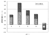
- Example 3 is a graph showing measurement results of Example 1.
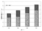
- 6 is a graph showing measurement results of Example 2.
- 10 is a graph showing measurement results of Example 3.
- the line is in the region where the pH of the isoelectric point is 5, 6, 4, 8, 10 in order from the top.
- the “molecular interaction measurement method” refers to a substance (first substance) constituting the surface of a measurement member (sensor chip) and a substance (second substance) contained in a solution brought into contact with the surface.
- the amount of adsorption can be evaluated quantitatively by observing a signal that appears when a second substance is adsorbed on the first substance and the state of the sensor chip surface changes due to an intermolecular interaction between them. It is a general term for possible methods. However, a method using a substance labeled with an enzyme, fluorescent substance, radioactive isotope or the like for producing a fluorescent dye as the second substance is excluded.
- Typical examples of the intermolecular interaction measurement method as described above include RIfS, QCM, and SPR.
- RIfS the intermolecular interaction measurement method in the present invention is not limited to RIfS.
- a person skilled in the art can implement the present invention by a method for measuring intermolecular interactions other than RIfS by replacing the items related to RIfS with the corresponding items in QCM, SPR and the like based on the description in this specification. It is.
- an outline of an intermolecular interaction measurement system 1 based on the RIfS method, which is an embodiment for carrying out the isoelectric point measurement system of the present invention, will be described with reference to FIGS.
- the intermolecular interaction measurement system 1 executes the isoelectric point measurement method of the present invention, and the computer included in the system configuration executes a program reflecting the isoelectric point measurement program of the present invention. It is remembered as possible.
- the intermolecular interaction measurement system 1 is usually configured to output various measurement values, but in the following, the optical film thickness of the interference film is exclusively related to the implementation of the isoelectric point measurement method of the present invention. The measurement will be described.
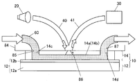
- the intermolecular interaction measurement system 1 includes a measuring member 10 that serves as a field for measuring intermolecular interactions (in the present invention, ie, an isoelectric point measuring field), and a light source and a spectroscope described later.
- a measuring device 80 including a measuring mechanism, a control arithmetic device 50 that is a computer connected to the measuring device 80, a display 91 and an input / output device 92 connected to the control arithmetic device 50. Yes.
- control arithmetic device 50 includes a control unit for a measurement mechanism such as a light source and a spectroscope built in the measurement device 80, a calculation unit for detection information, and an input / output unit for inputting / outputting control commands and detection information. (Interface), and preferably further functions as an arithmetic means for executing the isoelectric point estimation method of the present invention.
- the measuring device 80 includes a lower housing 82 and an upper housing 81 that is rotatably attached to the lower housing 82.
- the lower housing 82 is provided with a table 83 for holding the measuring member 10.
- a connection portion 84 having an injection port 85 and a suction port 87 for connecting the measurement member 10 and circulating a sample and a detection window 86 is provided inside the upper housing 81.
- a white light source 20, a spectroscope 30, and optical fibers 40 and 41 are provided in the upper housing 81, and light is emitted from the detection window 86 and from the detection window 86. It is configured to receive incident light.
- the upper casing 81 When performing measurement, first, the upper casing 81 is rotated upward to open the table 83 on the lower casing 82, and the measuring member 10 is set on the table 83. Thereafter, the upper casing 81 is turned downward and closed, whereby the injection port 85 and the suction port 87 are connected to the measurement member 10 and the detection window 86 faces the measurement member 10 to complete the measurement preparation.
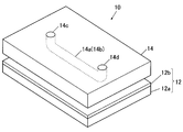
- the measurement member 10 includes a sensor chip 12 provided with an optical thin film and a flow cell 14 that forms a flow path together with the sensor chip 12.
- the sensor chip 12 has a silicon substrate 12a.
- a SiN film 12b (silicon nitride) is deposited on the silicon substrate 12a.
- the SiN film 12b is an example of an optical thin film.
- a charged layer 12c as a first material may be formed on the SiN film 12b.
- the flow cell 14 is a transparent member made of silicone rubber.
- a groove 14 a is formed in the flow cell 14.
- a sealed flow path 14b is formed as shown in FIG. Both ends of the groove 14a are exposed from the surface of the flow cell 14, and one end functions as a sample solution inlet 14c and the other end functions as an outlet 14d.
- the flow cell 14 can be replaced with the sensor chip 12, and the flow cell 14 can be used in a disposable manner.
- the surface of the sensor chip 12 may be modified with a silane coupling agent or the like. In this case, the flow cell 14 can be easily replaced.
- the upper casing 81 is rotated downward and closed, so that the detection window 86 faces the flow cell 14 as shown in FIG.
- the optical fiber 40 is installed above the path 14b.
- the white light source 20 is connected to one end of the optical fiber 40.
- a halogen light source is used as the white light source 20.
- a pseudo white light source having a plurality of spectral intensity peaks in the visible light wavelength region, such as an LED light source, may be used.
- the other end of the optical fiber 40 faces the detection window 86.
- the spectroscope 30 is connected to one end of the optical fiber 41, and the other end faces the detection window 86.
- the white light source 20 When the white light source 20 is turned on, the light is applied to the sealed flow path 14 b through the optical fiber 40, and the reflected light is detected by the spectrometer 30 through the optical fiber 41.
- the white light source 20 and the spectroscope 30 are connected to a control arithmetic device 50, and the control arithmetic device 50 controls the operation of these modules.
- control arithmetic device 50 executes data stored in a storage device 503 (see FIG. 4) described later, and stores data representing the spectral characteristics of reflected light through the interface at a predetermined timing linked to detection operation control. While obtaining an input, it functions as an arithmetic means for calculating a minimum reflectance wavelength based on the input data.
- FIG. 4 is a schematic circuit block diagram of the measurement system 1.
- the control arithmetic device 50 includes a CPU 500, a ROM 501, a RAM 502, a storage device 503 such as a hard disk, a communication device 504, a reader / writer 505 of a storage medium such as a memory card, and each part and display of the measurement device 80.
- An interface 506 is provided for exchanging signals with the input device.
- a program for executing the intermolecular interaction measurement method preferably a program for executing processing for estimating the isoelectric point of the test substance based on the measurement result and the measurement conditions is stored in the storage device 503.
- the CPU 500 is controlled by this program to execute various operations.
- the sample solution 60 is circulated from the inlet 14c to the outlet 14d through the sealed channel 14b.
- the control arithmetic device 50 controls the liquid feeding device 35 (see FIG. 4) for feeding the sample solution 60.
- the sample solution 60 include an aqueous solution in which a second substance as a substance having a known isoelectric point (reference substance) or a substance having an unknown isoelectric point (test substance) is dissolved according to the embodiment of the present invention. Used.
- the control arithmetic device 50 turns on the white light source 20 at a timing before the sample solution 60 flows into the measuring member 10, and the optical thin film (SiN film 12 b or charged layer 12 c before the start of intermolecular interaction from the spectroscope 30. ) To obtain spectral characteristic data including data indicating the intensity of the reflected light.
- the control arithmetic device 50 turns on the white light source 20 while the sample solution 60 is circulating in the closed flow path 14b.
- the white light passes through the flow cell 14 and is irradiated to the sensor chip 12, and the reflected light is detected by the spectroscope 30.
- the spectral characteristic of the reflected light detected by the spectroscope 30 is transmitted to the control arithmetic device 50.
- the control arithmetic device 50 obtains from the spectroscope 30 input of spectral characteristic data including data indicating the intensity of reflected light during or after the progress of the intermolecular interaction.
- spectral characteristic data necessary for measuring the isoelectric point is input to the control arithmetic unit 50.
- the sensor chip 12 has one or more interference films (SiN film 12b, charged layer 12c) on the substrate (silicon substrate 12a).
- the measurement system 1 can measure the optical film thickness of the interference film in the laminate by reflection interference spectroscopy.
- the optical fiber 40 receives irradiation light that irradiates light from the light source (white light source 20) to the laminate (sensor chip 12), and the optical fiber 41 receives reflected light from the laminate (sensor chip 12).
- the spectroscope 30 corresponds to a spectroscopic detector that detects the spectral characteristics of the reflected light.
- the RAM 502 brings the aqueous solution of the second substance into contact with data to be referred to when the control arithmetic unit 50 estimates the isoelectric point of the test substance, that is, a predetermined region on the sensor chip formed of the first substance. It functions as a storage means for the measurement result data when measuring the adsorption amount of the second substance to the region and the measurement condition data corresponding thereto.
- the data can be read from any of a storage device 503, a server connected via the communication device 504, an external storage device connected via the interface 506, a memory card read by the reader / writer 505, and the like. Good.
- the hardware configuration is not limited, for example, when another computer that has received spectral characteristic data necessary for measuring the isoelectric point via the communication device 504 performs an operation for measuring the isoelectric point.
- the other computer is a computer in which the isoelectric point measuring system of the present invention is installed and the isoelectric point measuring program of the present invention is installed.
- Data to be referred to when estimating the isoelectric point of the test substance is obtained by bringing an aqueous solution of the second substance into contact with a predetermined area on the sensor chip formed of the first substance, and adsorbing the second substance to the area. Measurement result data when the quantity is measured, and measurement condition data corresponding to the measurement result data.
- measurement is performed a plurality of times for a plurality of aqueous solutions or in two or more regions formed on the sensor chip according to the embodiment, so that each measurement result data and measurement condition data are accumulated and stored. Is done.
- the measurement result data is stored for a plurality of aqueous solutions in which the second substance is dissolved at the same concentration but different pH.
- the condition data the pH data of the aqueous solution of the second substance is stored.
- the measurement result data is stored for a plurality of aqueous solutions in which the second substance is dissolved at the same concentration but different pH, and the measurement condition data is Data on the isoelectric point of the two substances and the pH of the aqueous solution are stored.
- the measurement result data is stored for two or more regions formed on the sensor chip by the first substance having different isoelectric points, and is measured condition data.
- the data of the isoelectric point of the first substance is stored. Details of each embodiment of the isoelectric point measurement method will be described later.
- the measurement result data may be stored for each measurement, and the measurement condition data (the known isoelectric point of the first substance or the second substance, the pH of the aqueous solution of the second substance) is associated with the measurement result data. You only need to enter it in advance.
- measurement environment detection means such as a measurement environment detection member of the measurement device and its control means
- the pH of an aqueous solution in contact with a predetermined region on the sensor chip It is also possible to memorize each time together with the measurement of the intermolecular interaction.
- the flow cell 14 corresponds to a member that forms a flow path on the interference film.
- the measuring device 80 is connected to the flow path formed by the flow cell 14 and is connected to the first surface of the sensor chip.
- a liquid feeding means for flowing a liquid containing a second substance that interacts with one substance to the flow path is configured.
- an appropriate means may be provided.
- the optical fibers 40 and 41 are provided in each region (the system as a whole includes a set of a plurality of optical fibers 40 and 41), the intermolecular interaction can be measured independently in real time. it can.
- the optical fiber 40 that guides incident light and the optical fiber 41 that guides reflected light are movable (in this case, the detection window 86 is suitably provided so as to cover the entire region), or the measurement member 10.
- the table 83 for holding the screen may be movable.
- the isoelectric point measurement method is a method for measuring the isoelectric point of a substance (test substance) whose isoelectric point is unknown, using the intermolecular interaction measurement method, and measuring the intermolecular interaction.
- One of the first substance forming a predetermined region on the sensor chip and the second substance dissolved in the aqueous solution for contacting the region is the test substance, and the first substance Based on the step (1) of bringing the aqueous solution of the second substance into contact with a predetermined region on the formed sensor chip, the step (2) of measuring the adsorption amount of the second substance on the region, and the measurement result It includes a step (3) of estimating an isoelectric point of a test substance.
- steps (1), (2), and (3) and three typical embodiments of the isoelectric point measurement method will be sequentially described.
- the “substance with an unknown isoelectric point” refers to a substance intended to measure the isoelectric point using the isoelectric point measuring method of the present invention. Even if the point is a known substance, if the substance is intended to measure the isoelectric point using the isoelectric point measuring method of the present invention, the “isoelectric point is unknown” in the description of this specification. Falls under “substances”.
- Step (1) Contacting Step
- the first step in the isoelectric point measurement method is a step of bringing an aqueous solution of the second substance into contact with a predetermined region on the sensor chip formed of the first substance.
- This step can be performed by the “flow type” technique as described above for the system according to the present invention.
- an aqueous solution of a protein with an unknown isoelectric point prepared in advance is fed in a flow type system and brought into contact with the surface of a predetermined sensor chip. Good.
- this step may be performed by a “immersion type” method separately from the flow type system.
- a “immersion type” method separately from the flow type system.
- a sensor chip manufactured in this way there is no need to construct a measurement member combined with a flow cell, as described for the flow type system, and the sensor chip is set as it is in the measurement device, The following measurement steps can be performed.
- the second substance is typically a protein
- the aqueous solution is generally prepared by adding the second substance (protein) to a buffer adjusted to a desired pH.
- the pH of the buffer used for the measurement it is preferable to finely set the pH of the buffer used for the measurement within a predetermined range. Since the composition of the buffer solution having various pHs is known, it is possible to prepare an aqueous solution of the second substance having a desired pH by selecting an appropriate one and finely adjusting as necessary. .
- Step (2) Measurement Step
- the second step in the isoelectric point measurement method is a step of measuring the adsorption amount of the second substance to a predetermined region of the sensor chip according to the step (1). This step can also be performed using a conventional method for measuring intermolecular interactions, as specifically described in the present specification regarding the system according to the present invention.
- the amount of the substance adsorbed on the sensor chip is expressed as a change amount ( ⁇ ) of the reflectance minimum wavelength ( ⁇ ).
- Techniques such as measurement of ⁇ and correction of measurement data are not particularly limited, and various techniques can be employed.
- the basic measurement principle of ⁇ in the RIfS intermolecular interaction measurement method is as follows.
- the spectral intensity of the incident light (white light) itself to the unmodified sensor chip is represented by a solid line 106
- the spectral intensity of the reflected light is represented by a solid line 108.
- a reflection spectrum 110 having a bottom peak (minimum portion in the spectrum curve) represented by a solid line is obtained as shown in FIG.
- the thickness of the optical thin film at that portion changes, the optical path length changes, and the interference wavelength also changes due to the reflection interference effect. That is, the peak position of the spectral intensity distribution of the reflected light is shifted, and as a result, as shown in FIG. 6, the reflected spectrum 110 is shifted to the reflected spectrum 122 (see the dotted line portion).
- the second embodiment of the method for measuring the isoelectric point when a test substance (first substance) is first applied to the surface of an unmodified sensor chip to form a layer made of the substance, the same as above, a shift from the reflection spectrum 110 to the reflection spectrum 122 occurs.
- a reference substance (second substance) aqueous solution is contacted to form a reference substance layer on the test substance layer, the thickness of the optical thin film further changes.
- the reflection spectrum 122 is shifted to the reflection spectrum 132 (see the dashed line).
- the adhesion of the substance to the surface of the sensor chip forms a heterogeneous layer when viewed partially, but this heterogeneous layer is macroscopically determined according to a predetermined optical quantity corresponding to the amount of adhesion of the substance. It is replaced with a homogeneous layer having the thickness of a thin film. Accordingly, the optical thickness of the homogeneous layer through which incident light passes changes depending on the amount of the analyte 130 attached.
- the amount of the substance adsorbed by the intermolecular interaction can be quantified relative or absolute.
- ⁇ is 0 or sufficiently small (within a measurement error range), it can be considered that no substance is adsorbed on the sensor chip.
- the contact step (1) and the measurement step (2) are performed in parallel and simultaneously.
- the first embodiment of the isoelectric point measurement method is a case where the second substance in the aqueous solution is a test substance whose isoelectric point is unknown, and the second substance has the same concentration. After the steps (1) and (2) were performed on a plurality of aqueous solutions dissolved in pH but having different pHs, the measurement results of the respective aqueous solutions were compared as the step (3). And a step of estimating that the pH of the aqueous solution is the isoelectric point of the second substance.
- the first embodiment can be carried out using a normal unmodified sensor chip (without a charged layer).
- the optical thin film made of SiN formed on the surface of the sensor chip for unmodified RIfS has a uniform surface potential near zero, and the adsorption amount of the second substance is quantified between aqueous solutions having different pHs. There is practically no problem in comparison.
- the first substance on the sensor chip is a test substance whose isoelectric point is unknown, and the second substance in the aqueous solution is isoelectric.
- the steps (1) and (2) are performed on a plurality of aqueous solutions in which the second substance is dissolved at the same concentration but different in pH, and then the process (3)
- the unknown isoelectric point of the first substance depends on whether the pH of the aqueous solution having the largest amount of adsorption is higher or lower than the known isoelectric point of the second substance.
- Including the step of estimating whether is higher or lower than the known isoelectric point of the second substance Specifically, if the pH of the referenced aqueous solution is higher than the isoelectric point of the second substance, the isoelectric point of the first substance is estimated to be higher than the isoelectric point of the second substance, and the pH of the referenced aqueous solution is If it is lower than the isoelectric point of the two substances, it is estimated that the isoelectric point of the first substance is lower than the isoelectric point of the second substance.
- a sensor chip having a region formed of a test substance on the surface is used.
- a sensor chip is formed by laminating a layer made of a test substance on the upper surface of an optical thin film made of SiN formed on the surface of an unmodified sensor chip for RIfS using a known method such as coating. Can be produced.
- a substance containing both a cationic functional group and an anionic functional group for example, an ionic polymer described herein or a mixture thereof (resin composition) may be used as the test substance in the second embodiment. That is, in the second embodiment of the isoelectric point measurement method, the sensor chip according to the present invention is provided with a region formed by a substance containing both a cationic functional group and an anionic functional group for which the isoelectric point is to be measured. Can be used. When there are two or more kinds of such test substances, a cationic functional group and an anionic property are formed on one sensor chip as in the sensor chip used in the third embodiment of the isoelectric point measuring method described below. Two or more regions formed by substances having different isoelectric points according to the mixing ratio of the functional groups may be formed, and the test substance in each region is simultaneously measured in parallel with this isoelectric point measurement method. It is also possible to implement the second embodiment.
- an optical thin film made of SiN is formed on the surface of an unmodified RIfS sensor chip, and it is known that the surface potential is uniform near zero, but it is strictly charged positively or negatively. If, in other words, it is unknown whether or not there is an isoelectric point at which the charge is strictly zero, the optical thin film made of SiN may be treated as a test substance (see Examples below) ).
- the first substance on the sensor chip is a reference substance whose isoelectric point is known
- the second substance in the aqueous solution is the isoelectric point.
- the step (3) includes a step of comparing the measurement results of the respective regions and estimating that the isoelectric point of the first material forming the region with the largest amount of adsorption is the isoelectric point of the second material. It is a waste.
- a sensor chip having two or more regions formed by substances having different isoelectric points (the first substance) is used.
- a sensor chip differs depending on the mixing ratio of the cationic functional group and the anionic functional group in one sensor chip (one sealed channel).
- Those including two or more regions formed by a substance having an isoelectric point are preferable.
- one region is formed with a substance having one kind of isoelectric point per sealed channel, and one sensor chip having a plurality of such sealed channels is used, or one sheet
- the third embodiment of the isoelectric point measurement method is carried out even if one region is formed of a substance having one kind of isoelectric point per sensor chip and a plurality of such sensor chips are used as a set. Is possible.
- the two or more regions have a higher isoelectric point from one end of the sensor chip toward the other end (from the upstream side to the downstream side of the sealed channel).
- a stepped gradient is formed from the lower side to the higher side.
- a sensor chip including a region (sometimes referred to as “charged layer” in the present invention) formed by a substance having both a cationic functional group and an anionic functional group is used. There is.
- the third embodiment of the isoelectric point measurement method different isoelectric points according to the mixing ratio of the cationic functional group and the anionic functional group are used as substances having a known isoelectric point (reference substance).
- a sensor chip having two or more regions (charged layers) formed of a substance having the same can be used (see FIG. 7).
- a substance having both a cationic functional group and an anionic functional group may be used for measurement as a substance (test substance) whose isoelectric point is unknown. .
- the mixing ratio is appropriately set so that the charged layer has a desired isoelectric point. Adjust it.
- a plurality of materials for example, ionic properties
- a mixture of polymers is prepared, and a region composed of them is sequentially formed on the surface of the sensor chip, whereby an isoelectric point gradient can be generated.
- the method for forming the charged layer on the surface of the sensor chip is not particularly limited.
- a cationic functional group, an anionic functional group, or both It is preferable to form an electrically charged layer by using an “ionic polymer” having a general term “ionic functional group”) and applying it to the surface of the sensor chip.
- Cationic functional group examples include guanidinium ion, —NH 3 + , —NH 2 (CH 3 ) + , —NH (CH 3 ) 2 + , —N (CH 3 ) 3 + And quaternary ammonium cations.
- Such cationic functional groups are preferably those that form an inner salt, such as halogen anions such as chlorine and bromine, sulfate anions, sulfonate anions, phosphate anions, carboxylate anions and the like. It may combine to form a counter salt. From the viewpoint of achieving a high surface charge density, it is preferable to use a quaternary ammonium cation.
- an inner salt such as halogen anions such as chlorine and bromine, sulfate anions, sulfonate anions, phosphate anions, carboxylate anions and the like. It may combine to form a counter salt.
- the anionic functional group anionic functional group for example, -CO 2 - (carboxylic acid groups), - SO 3 - (sulfonic acid groups), - OSO 3 - (sulfate group), - OPO 4 - (phosphoric acid Group), -B (OH) 2 (boronic acid) and the like.
- Such an anionic functional group preferably forms an inner salt, but may be bonded to a metal cation or an organic cation.
- the metal cation include alkali metals such as Na + (sodium cation), K + (potassium cation), and Ca + (calcium cation).
- the organic cation include Me 3 N +. H (trimethylammonium cation), Et 3 N + H (triethylammonium cation), Me 2 N + H 2 (dimethylammonium cation) and the like can be mentioned.
- the charged layer may be formed using an ionic polymer having both an anionic functional group and a cationic functional group in one molecule, or only an anionic functional group in one molecule.
- the charged layer may be formed using a composition containing an anionic polymer having a cation and a cationic polymer having only a cationic functional group in one molecule.
- the ionic polymer may be obtained by polymerizing a monomer having an anionic functional group, a cationic functional group, or both in advance, and has other functional groups that can induce or introduce these functional groups. It may be obtained by polymerizing monomers and then inducing or introducing these functional groups into the functional group.
- the ionic functional group may be directly bonded to the polymer to be the main chain, or may be bonded to the polymer main chain via another bonding group R (AR-polymer main chain).
- R AR-polymer main chain
- Examples of the bonding group —R— include an alkylene group having 1 to 6 carbon atoms, a phenylene group, and an ethyleneoxy group ((C 2 H 4 O) n ).
- Examples of ionic polymers include those having a hydrocarbon skeleton as the main chain.
- Examples of the monomer used for synthesizing such an ionic polymer include monomers having a vinyl group, an allyl group, a diene, and the like.
- amides such as (meth) acrylamide; (meth) acrylic acid or carboxylic acids such as vinyl formate, vinyl acetate, allyl acetate, allyl acetoacetate, vinylmaleic acid or esters thereof; styrene Sulfonic acid or sulfonic acid such as styrene sulfonic acid ester or esters thereof; in addition, sulfuric acid ester, phosphoric acid ester, phosphonic acid ester and the like are also included.
- urethane resins into which ionic functional groups have been introduced such as cationic or anionic water-based polyurethane resins “Hydran (registered trademark)” series (DIC Corporation), can be cited as ionic polymers.
- amino acid polymers such as polyaspartic acid, polyglutamic acid, polyargylic acid having a carboxyl group (anionic functional group) in the side chain, or polylysine having an amino group (cationic functional group) in the side chain, or carboxymethyl dextran
- a derivative obtained by introducing an ionic functional group such as a carboxyl group into a polysaccharide such as dextran via a hydroxyl group or the like in a glucose unit can also be mentioned as an ionic polymer.
- the various ionic polymers as described above can be synthesized by known methods, and can also be obtained as commercial products.
- the properties of the ionic polymer such as the number of ionic functional groups per molecule and the number average molecular weight, can be appropriately adjusted according to the charge state of the target sensor chip surface.
- a silane coupling agent having an amino group at the terminal and a silane coupling agent having a carboxyl group are mixed in a stepwise desired ratio, and the mixture is mixed with a polysaccharide such as agarose, so By performing a dehydration condensation reaction, it is possible to prepare an ionic polymer that produces a desired proportion of charge states.
- the ionic polymer can be applied to the surface of the sensor chip using a known method such as dip coating, spin coating, or spray coating.
- a coating solution may be prepared by dissolving in an appropriate solvent so as to have an appropriate concentration according to the type of ionic polymer, and this may be applied.
- a desired technique is used. It is possible to form such a region by applying the desired ionic polymer to the region (position and size).
- a SAM Self-Assembled Monolayer
- a silane coupling agent having an amino group or a carboxyl group at the end is formed on the surface of the sensor chip, and other methods are added as necessary.
- a charged layer can also be formed by reacting the above compound.
- the charged layer can be formed in situ using a radical living polymerization method in which the initiator is immobilized directly on the substrate or via the SAM, and the molecular length can be controlled by sequential reaction.
- the sensor chip 10 is generally manufactured using a rectangular and flat substrate 12a (a flow cell 14 is loaded as necessary to form a sealed channel). It is also possible to manufacture using a “well type” in which a plurality of sections are formed by unevenness instead of a flat surface.
- the substrate 12a is preferably made of, for example, Si (silicon).
- the optical thin film 12b is selected according to the material (refractive index) of the substrate so that the minimum reflectance wavelength observed when white light is used falls within an appropriate range (preferably in the visible light region). It is made of a material having a refractive index and a thickness.
- the optical thin film 12b is an oxide film or nitride film such as SiN, Ta 2 O 5 , Nb 2 O 5 , HfO 2 , ZrO 2 , ITO (indium tin oxide). Is preferable, and a SiN film is particularly preferable.
- Each of these oxide films and nitride films has a refractive index of 1.8 to 2.4 in the visible light region (wavelength range of about 400 to 800 nm), and is an optical thin film formed on the surface layer side layer of the Si substrate.
- the optical thin film itself has the effect of suppressing non-specific adsorption to some extent while satisfying the performance. For example, by setting the thickness of the SiN film to about 45 to 90 nm, the bottom peak can be adjusted to a range of about 400 nm to 800 nm.
- the isoelectric point measurement program of the present invention causes the computer to execute a process of estimating the isoelectric point of the test substance based on the measurement result and the measurement conditions in step (3) of the isoelectric point measurement method of the present invention.
- the computer is caused to function as a calculation means for executing the processing.
- an isoelectric point measurement program an aqueous solution of the second substance was brought into contact with a predetermined region on the sensor chip formed of the first substance, and the adsorption amount of the second substance on the region was measured.
- the measurement result data stored at the time and the reading process for reading the corresponding measurement condition data, and comparing the read measurement result data with each other, based on the measurement result data satisfying a predetermined condition and the corresponding measurement condition data,
- a program for causing a computer to execute an estimation process for estimating the isoelectric point of the test substance can be used.
- the reading process and the estimation process may be appropriate according to an embodiment of the isoelectric point measurement method of the present invention, typically the first to third embodiments.
- the second substance is a test substance
- the measurement result data includes a plurality of aqueous solutions in which the second substance is dissolved at the same concentration but has different pH.
- the data of the pH of the aqueous solution of the second substance is stored as measurement condition data.
- the estimation process of the program for the first embodiment includes a step of comparing the read measurement result data to extract data having the maximum adsorption amount, and an aqueous solution of the second substance corresponding to the extracted data. It includes a step of referring to pH data and a step of presenting the referred pH as an estimated value of the isoelectric point of the second substance.
- the first substance is the test substance
- the second substance is the reference substance
- the second substance is dissolved at the same concentration as the measurement result data
- the pH Are stored for a plurality of different aqueous solutions
- the isoelectric point of the second substance and the pH data of the aqueous solution are stored as measurement condition data.
- Such a program estimation process for the second embodiment includes a step of comparing the read measurement result data to extract data having the maximum adsorption amount, and isoelectricity of the second substance corresponding to the extracted data.
- the isoelectric point of the first substance is higher than the isoelectric point of the second substance depending on whether the pH of the aqueous solution referred to is higher or lower than the isoelectric point of the second substance. Presenting an estimation result of high or low.
- the first substance is a reference substance
- the second substance is a test substance
- a sensor is used as a measurement result data by a first substance having a different isoelectric point.
- Data on two or more regions formed on the chip are stored, and data on the isoelectric point of the first substance is stored as measurement condition data.
- Such a program estimation process for the third embodiment includes a step of comparing the read measurement result data to extract data having the maximum adsorption amount, and an isoelectric of the second substance corresponding to the extracted data.
- the isoelectric point of the first substance is higher than the isoelectric point of the second substance depending on whether the pH of the aqueous solution referred to is higher or lower than the isoelectric point of the second substance. Presenting an estimation result of high or low.
- the program for executing the above steps can be prepared according to a conventional method.
- the program can be updated to the latest one as appropriate through the communication device 504 connected to a public line such as the Internet through a LAN or the like.
- MI-Affinity registered trademark, Konica Minolta Opto Co., Ltd.
- MI--Affinity dedicated sensor chip substrate: silicon wafer, optical thin film: silicon nitride
- flow cell PDMS, width 2.5 mm x length 16 mm x depth 0.1 mm, and 1 mm in diameter at both ends of the groove
- Econoflo Syringe Pump 70-2205 manufactured by Harvard Apparatus
- Example 1 In each of acetate buffer (pH 4, 5, 6), phosphate buffered saline (pH 7.4) and carbonate buffer (pH 10) adjusted to pH 4, 5, 6, 7.4, 10, BSA was added and dissolved to a concentration of 10 ⁇ g / mL. An unmodified sensor chip (the surface potential of the optical thin film made of SiN is uniform around zero) was immersed in each BSA solution for 24 hours or 48 hours, then taken out, washed with distilled water, and dried.
- the reflectance minimum wavelength ( ⁇ ) of each sensor chip was measured by the RIfS measurement device at each time point before and after the above processing, and the amount of change ( ⁇ ) was calculated.
- Example 2 BSA was added to each of the acetate buffers adjusted to pH 4.5, 4.6, 4.8 and 5.0 so as to have a concentration of 10 ⁇ g / mL and dissolved.
- An unmodified sensor chip (the surface potential of the optical thin film made of SiN is uniform around zero) was immersed in each BSA solution for 1 hour or 3 hours, then taken out, washed with distilled water, and dried.
- the reflectance minimum wavelength ( ⁇ ) of each sensor chip was measured by the RIfS measurement device at each time point before and after the above processing, and the amount of change ( ⁇ ) was calculated.
- Example 3 [1] Preparation of isoelectric gradient-forming sensor chip: A silane coupling agent having a carboxyl group and an amino group at the end, Triethoxysilylpropylameric acid and 3-Aminopropyltrimethylsiloxane are added to ethanol to a concentration of 2 vol%, respectively. Furthermore, 2 vol% of acetic acid was added, and the silane coupling agent was hydrolyzed at room temperature for 1 hour.
- the hydrolyzed silane coupling solution was blended so that both ratios were 10: 0, 7.5: 2.5, 5: 5, 2.5: 7.5, 0:10, It was added to an aqueous solution (50 ° C.) of 2 wt% agarose (gelation temperature 36 ° C.) in the same amount as the solution, and reacted at 50 ° C. for 1 hour.
- aqueous solution 50 ° C.
- 2 wt% agarose gelation temperature 36 ° C.
- the reflectance minimum wavelength ( ⁇ ) is measured by optical fiber installed at the position corresponding to each area of the sensor chip in real time before and after the contact, and the amount of change ( ⁇ ) is monitored. did.
Landscapes
- Physics & Mathematics (AREA)
- Engineering & Computer Science (AREA)
- Mathematical Physics (AREA)
- Theoretical Computer Science (AREA)
- Spectroscopy & Molecular Physics (AREA)
- Health & Medical Sciences (AREA)
- Life Sciences & Earth Sciences (AREA)
- Chemical & Material Sciences (AREA)
- Analytical Chemistry (AREA)
- Biochemistry (AREA)
- General Health & Medical Sciences (AREA)
- General Physics & Mathematics (AREA)
- Immunology (AREA)
- Pathology (AREA)
- Investigating Or Analysing Materials By Optical Means (AREA)
Description
本発明は、等電点の測定方法および分子間相互作用測定方法(RIfS等)に関する。
タンパク質はペプチド結合により連結した多数のアミノ酸によって構成されるが、このアミノ酸の中には、側鎖が正に荷電しうる塩基性アミノ酸(リジン、アルギニン、ヒスチジン)および負に荷電しうる酸性アミノ酸(アスパラギン酸、グルタミン酸)が含まれている。そのため、タンパク質はそれを構成するアミノ酸残基の組成によって、生体内環境において通常は正または負に荷電している(タンパク質全体のうちでは負に荷電しているものが多い)が、特定のpHにおいて正味の電荷がゼロとなる。このときのpHを等電点と呼ぶ。一般的に、塩基性アミノ酸が多いタンパク質の等電点はアルカリ側であり、酸性アミノ酸が多いタンパク質の等電点は酸性側である。タンパク質の等電点は、タンパク質の結晶化や精製の適切な条件を設定する上で、またはタンパク質の構造解析を行う上で有用な情報となる。
タンパク質の等電点を測定する方法としては、たとえば、マイナス電荷を有する微粒子へのタンパク質の吸着量がpH依存性であり、等電点付近で吸着量が最大になることに基づき、HPLCを用いてその吸着量を測定し、タンパク質の等電点を推定する方法が知られている(非特許文献1)。
また、電気泳動によりタンパク質の等電点を測定する方法もある。一般的には、水溶性の両性担体に電気浸透流によりpH勾配を形成させて電気泳動を行う手法が用いられているが、ゲル自体にpH勾配を形成する「固定化pH勾配等電点電気泳動」も知られている。固定化pH勾配等電点電気泳動用のアクリルアミドゲルは、アクリルアミドとビスアクリルアミドを重合する際に、弱酸または弱塩基の解離基を持つアクリルアミド誘導体を加え、マトリックスの側鎖にその解離基を導入することで、pH勾配を固定化している。いずれの方法も、電気泳動後に染色をし、タンパク質が吸着した位置からpHを決定できる。
一方、抗原抗体反応のような生体高分子同士の分子間相互作用を測定することのできる方法として、従来のような放射性物質や蛍光体のような標識を用いない、ノンラベルの分子間相互作用測定方法が開発されている。このような分子間相互作用測定方法は、測定部材(センサーチップ)上で分子間相互作用が起きたときに発生するシグナルを各種の方式で検出するものであり、たとえば、光学薄膜の干渉色変化を利用するRIfS(Reflectometric Interference Spectroscopy:反射型干渉分光法)方式、QCM(Quartz Crystal Microbalance:水晶発振子マイクロバランス)方式などが知られている。RIfS方式の基本原理は、特許文献1などで言及されている。
白浜博幸,蛋白質の高分子表面への吸着現象とそのバイオメディカル分野への応用,蛋白質 核酸 酵素, Vol. 37, No. 2, pp.117-129, 1992.
上述したような従来の方法のうち、HPLCを用いる方法は、カラムの作製や操作手法の特性上、実験者や実験条件による差が出やすく、しかもその差が大きいという問題がある、また、実験操作に手間と時間がかかることから、試料数を増やしたり追試をすることにも難点があった。また、電気泳動を用いる方法は、ゲル膜の生成状態や染色による評価方法に実験者ごとの差が大きいことから、客観的な指標としてデータを検証することが困難であった。
このような状況の下、本発明は、従来よりも簡便かつ迅速に行うことができ、しかも信頼性の高い客観的なデータを得ることができる等電点の測定方法を提供することを目的とする。
発明者らは、分子間相互作用測定方法を応用し、等電点が未知の被験物質と等電点が既知の参照物質とを静電的相互作用によりセンサーチップの表面に吸着させることにより、タンパク質やセンサーチップの表面の物質などの等電点を測定することができることを見いだした。
さらに、正の電荷を有する(カチオン性)官能基および負の電荷を有する(アニオン性)官能基の両方を含む物質を用いて形成された、所定の領域を備えた分子間相互作用測定用のセンサーチップが、上記のような等電点の測定方法の特定の実施形態を可能にすることを見いだし、本発明を完成させるに至った。
すなわち、本発明は下記の事項を包含する。
[1] 分子間相互作用測定用のセンサーチップ上の所定の領域を形成している第1物質および当該領域に接触させるための水溶液に溶解している第2物質のうちの一方が、等電点が未知の物質(以下「被験物質」と称する。)であるときに、分子間相互作用測定方法を用いて当該被験物質の等電点を測定する方法であって、
前記第1物質により形成されたセンサーチップ上の所定の領域に前記第2物質の水溶液を接触させる工程(1)、当該領域への前記第2物質の吸着量を測定する工程(2)、および測定結果とその測定条件に基づき前記被験物質の等電点を推定する工程(3)を含むことを特徴とする、等電点の測定方法。
前記第1物質により形成されたセンサーチップ上の所定の領域に前記第2物質の水溶液を接触させる工程(1)、当該領域への前記第2物質の吸着量を測定する工程(2)、および測定結果とその測定条件に基づき前記被験物質の等電点を推定する工程(3)を含むことを特徴とする、等電点の測定方法。
[2] 前記第2物質が被験物質である場合において、
前記第2物質が同一の濃度で溶解しているがpHの異なる複数の水溶液について、前記工程(1)および(2)を行った後、前記工程(3)として、各水溶液の測定結果を比較して、吸着量が最大だった水溶液のpHが前記第2物質の等電点であると推定する工程を含むことを特徴とする、[1]に記載の等電点の測定方法。
前記第2物質が同一の濃度で溶解しているがpHの異なる複数の水溶液について、前記工程(1)および(2)を行った後、前記工程(3)として、各水溶液の測定結果を比較して、吸着量が最大だった水溶液のpHが前記第2物質の等電点であると推定する工程を含むことを特徴とする、[1]に記載の等電点の測定方法。
[3] 前記第1物質が被験物質であり、前記第2物質が等電点が既知の物質(以下「参照物質」と称する。)である場合において、
前記第2物質が同一の濃度で溶解しているがpHの異なる複数の水溶液について、前記工程(1)および(2)を行った後、前記工程(3)として、各水溶液の測定結果を比較して、吸着量が最大だった水溶液のpHが前記第2物質の等電点より高いか低いかによって、前記第1物質の等電点が前記第2物質の等電点より高いか低いかを推定する工程を含むことを特徴とする、[1]に記載の等電点の測定方法。
前記第2物質が同一の濃度で溶解しているがpHの異なる複数の水溶液について、前記工程(1)および(2)を行った後、前記工程(3)として、各水溶液の測定結果を比較して、吸着量が最大だった水溶液のpHが前記第2物質の等電点より高いか低いかによって、前記第1物質の等電点が前記第2物質の等電点より高いか低いかを推定する工程を含むことを特徴とする、[1]に記載の等電点の測定方法。
[4] 前記第1物質が参照物質であり、前記第2物質が被験物質である場合において、
異なる等電点を有する第1物質によってセンサーチップ上に形成された2以上の領域において、前記工程(1)および(2)を行った後、前記工程(3)として、各領域の測定結果を比較して、吸着量が最大だった領域を形成する前記第1物質の等電点が前記第2物質の等電点であると推定する工程を含むことを特徴とする、[1]に記載の等電点の測定方法。
異なる等電点を有する第1物質によってセンサーチップ上に形成された2以上の領域において、前記工程(1)および(2)を行った後、前記工程(3)として、各領域の測定結果を比較して、吸着量が最大だった領域を形成する前記第1物質の等電点が前記第2物質の等電点であると推定する工程を含むことを特徴とする、[1]に記載の等電点の測定方法。
[5] 前記分子間相互作用測定方法がRIfSに基づくものである、[1]~[4]のいずれか一項に記載の等電点の測定方法。
[6] 表面に、カチオン性官能基およびアニオン性官能基の両方を含む物質によって形成された領域を備えることを特徴とする、分子間相互作用測定方法用のセンサーチップ。
[7] 前記領域が、カチオン性官能基およびアニオン性官能基の混合比率に応じた異なる等電点を有する物質によって形成された2以上の領域を含む、[6]に記載のセンサーチップ。
[8] 前記2以上の領域が、等電点の高低についての段階的な勾配を形成している、[6]または[7]に記載のセンサーチップ。
[9] 前記領域が、カチオン性官能基およびアニオン性官能基の両方を有するイオン性ポリマーにより形成されている、あるいはカチオン性官能基を有するイオン性ポリマーとアニオン性官能基を有するイオン性ポリマーとの混合物により形成されている、[6]~[8]のいずれか一項に記載のセンサーチップ。
[10] 前記センサーチップがRIfS用のものである、[6]~[9]のいずれか一項に記載のセンサーチップ。
[11] センサーチップ上に形成された2以上の領域のそれぞれにおいて、分子間相互作用による物質の吸着量を測定するための手段を備えることを特徴とする、分子間相互作用測定装置。
[12] 分子間相互作用測定用のセンサーチップ上の所定の領域を形成している第1物質および当該領域に接触させるための水溶液に溶解している第2物質のうちの一方が被験物質であるときに、分子間相互作用測定方法を利用して前記被験物質の等電点を測定するためのシステムであって、
前記第1物質により形成されたセンサーチップ上の所定の領域に前記第2物質の水溶液を接触させ、当該領域への前記第2物質の吸着量を測定したときの測定結果データと、それに対応する測定条件データとを記憶する記憶手段、および
前記記憶手段から前記測定結果データおよび前記測定条件データを読み出す読出処理と、読み出した測定結果データ同士を比較し、所定の条件を満たす測定結果データとそれに対応する測定条件データに基づき、前記被験物質の等電点を推定する推定処理とを実行するための演算手段
を備えることを特徴とする、等電点測定システム。
前記第1物質により形成されたセンサーチップ上の所定の領域に前記第2物質の水溶液を接触させ、当該領域への前記第2物質の吸着量を測定したときの測定結果データと、それに対応する測定条件データとを記憶する記憶手段、および
前記記憶手段から前記測定結果データおよび前記測定条件データを読み出す読出処理と、読み出した測定結果データ同士を比較し、所定の条件を満たす測定結果データとそれに対応する測定条件データに基づき、前記被験物質の等電点を推定する推定処理とを実行するための演算手段
を備えることを特徴とする、等電点測定システム。
[13] 前記第2物質が被験物質であるとき、
前記記憶手段が、前記測定結果データとして、第2物質が同一の濃度で溶解しているがpHの異なる複数の水溶液についてのものと、前記測定条件データとして、第2物質の水溶液のpHのデータとを記憶するものであり、
前記演算手段が、前記推定処理として、読み出した測定結果データ同士を比較して吸着量が最大のデータを抽出するステップと、抽出したデータに対応する第2物質の水溶液のpHのデータを参照するステップと、参照したpHを第2物質の等電点の推定値として提示するステップとを含むものである、
[12]に記載の等電点測定システム。
前記記憶手段が、前記測定結果データとして、第2物質が同一の濃度で溶解しているがpHの異なる複数の水溶液についてのものと、前記測定条件データとして、第2物質の水溶液のpHのデータとを記憶するものであり、
前記演算手段が、前記推定処理として、読み出した測定結果データ同士を比較して吸着量が最大のデータを抽出するステップと、抽出したデータに対応する第2物質の水溶液のpHのデータを参照するステップと、参照したpHを第2物質の等電点の推定値として提示するステップとを含むものである、
[12]に記載の等電点測定システム。
[14] 前記第1物質が被験物質であり、前記第2物質が参照物質であるとき、
前記記憶手段が、前記測定結果データとして、第2物質が同一の濃度で溶解しているがpHの異なる複数の水溶液についてのものと、前記測定条件データとして、第2物質の等電点およびその水溶液のpHのデータとを記憶するものであり、
前記演算手段が、前記推定処理として、読み出した測定結果データ同士を比較して吸着量が最大のデータを抽出するステップと、抽出したデータに対応する第2物質の等電点およびその水溶液のpHのデータを参照するステップと、参照した水溶液のpHが第2物質の等電点より高いか低いかによって、第1物質の等電点が第2物質の等電点より高いか低いかの推定結果を提示するステップとを含むものである、
[12]に記載の等電点測定システム。
前記記憶手段が、前記測定結果データとして、第2物質が同一の濃度で溶解しているがpHの異なる複数の水溶液についてのものと、前記測定条件データとして、第2物質の等電点およびその水溶液のpHのデータとを記憶するものであり、
前記演算手段が、前記推定処理として、読み出した測定結果データ同士を比較して吸着量が最大のデータを抽出するステップと、抽出したデータに対応する第2物質の等電点およびその水溶液のpHのデータを参照するステップと、参照した水溶液のpHが第2物質の等電点より高いか低いかによって、第1物質の等電点が第2物質の等電点より高いか低いかの推定結果を提示するステップとを含むものである、
[12]に記載の等電点測定システム。
[15] 前記第1物質が参照物質であり、前記第2物質が被検物質であるとき、
前記記憶手段が、前記測定結果データとして、異なる等電点を有する第1物質によってセンサーチップ上に形成された2以上の領域についてのものと、前記測定条件データとして、第1物質の等電点のデータとを記憶するものであり、
前記演算手段が、前記推定処理として、読み出した測定結果データ同士を比較して吸着量が最大のデータを抽出するステップと、抽出したデータに対応する第1物質の等電点を参照するステップと、参照した等電点を第2物質の等電点の推定値として提示するステップとを含むものである、
[12]に記載の等電点測定システム。
前記記憶手段が、前記測定結果データとして、異なる等電点を有する第1物質によってセンサーチップ上に形成された2以上の領域についてのものと、前記測定条件データとして、第1物質の等電点のデータとを記憶するものであり、
前記演算手段が、前記推定処理として、読み出した測定結果データ同士を比較して吸着量が最大のデータを抽出するステップと、抽出したデータに対応する第1物質の等電点を参照するステップと、参照した等電点を第2物質の等電点の推定値として提示するステップとを含むものである、
[12]に記載の等電点測定システム。
[16] センサーチップ上の所定の領域と接触する水溶液のpHを測定する測定環境検知手段を備える、[12]に記載の等電点測定システム。
[17] センサーチップ上に形成された2以上の領域において分子間相互作用の測定を行う手段を備える、[12]に記載の等電点測定システム。
[18] 分子間相互作用測定用のセンサーチップ上の所定の領域を形成している第1物質および当該領域に接触させるための水溶液に溶解している第2物質のうちの一方が被験物質であるときに、分子間相互作用測定方法を利用して前記被験物質の等電点を測定する方法において、測定結果とその測定条件に基づき前記被験物質の等電点を推定する処理をコンピュータに実行させるためのプログラムであって、
前記第1物質により形成されたセンサーチップ上の所定の領域に前記第2物質の水溶液を接触させ、当該領域への前記第2物質の吸着量を測定したときに記憶された測定結果データと、それに対応する測定条件データを読み出す読出処理、および
読み出した測定結果データ同士を比較し、所定の条件を満たす測定結果データとそれに対応する測定条件データに基づき、前記被験物質の等電点を推定する推定処理
を前記コンピュータに行わせることを特徴とする、等電点測定プログラム。
前記第1物質により形成されたセンサーチップ上の所定の領域に前記第2物質の水溶液を接触させ、当該領域への前記第2物質の吸着量を測定したときに記憶された測定結果データと、それに対応する測定条件データを読み出す読出処理、および
読み出した測定結果データ同士を比較し、所定の条件を満たす測定結果データとそれに対応する測定条件データに基づき、前記被験物質の等電点を推定する推定処理
を前記コンピュータに行わせることを特徴とする、等電点測定プログラム。
[19] 前記第2物質が被験物質であるとき、
前記測定結果データが、第2物質が同一の濃度で溶解しているがpHの異なる複数の水溶液についてのものであり、
前記測定条件データが、第2物質の水溶液のpHのデータであり、
前記推定処理が、読み出した測定結果データ同士を比較して吸着量が最大のデータを抽出するステップと、抽出したデータに対応する第2物質の水溶液のpHのデータを参照するステップと、参照したpHを第2物質の等電点の推定値として提示するステップとを含む、
[18]に記載の等電点測定プログラム。
前記測定結果データが、第2物質が同一の濃度で溶解しているがpHの異なる複数の水溶液についてのものであり、
前記測定条件データが、第2物質の水溶液のpHのデータであり、
前記推定処理が、読み出した測定結果データ同士を比較して吸着量が最大のデータを抽出するステップと、抽出したデータに対応する第2物質の水溶液のpHのデータを参照するステップと、参照したpHを第2物質の等電点の推定値として提示するステップとを含む、
[18]に記載の等電点測定プログラム。
[20] 前記第1物質が被験物質であり、前記第2物質が参照物質であるとき、
前記測定結果データが、第2物質が同一の濃度で溶解しているがpHの異なる複数の水溶液についてのものであり、
前記測定条件データが、第2物質の等電点およびその水溶液のpHのデータであり、
前記推定処理が、読み出した測定結果データ同士を比較して吸着量が最大のデータを抽出するステップと、抽出したデータに対応する第2物質の等電点およびその水溶液のpHのデータを参照するステップと、参照した水溶液のpHが第2物質の等電点より高いか低いかによって、第1物質の等電点が第2物質の等電点より高いか低いかの推定結果を提示するステップとを含む、
[18]に記載の等電点測定プログラム。
前記測定結果データが、第2物質が同一の濃度で溶解しているがpHの異なる複数の水溶液についてのものであり、
前記測定条件データが、第2物質の等電点およびその水溶液のpHのデータであり、
前記推定処理が、読み出した測定結果データ同士を比較して吸着量が最大のデータを抽出するステップと、抽出したデータに対応する第2物質の等電点およびその水溶液のpHのデータを参照するステップと、参照した水溶液のpHが第2物質の等電点より高いか低いかによって、第1物質の等電点が第2物質の等電点より高いか低いかの推定結果を提示するステップとを含む、
[18]に記載の等電点測定プログラム。
[21] 前記第1物質が参照物質であり、前記第2物質が被検物質であるとき、
前記測定結果データが、異なる等電点を有する第1物質によってセンサーチップ上に形成された2以上の領域についてのものであり、
前記測定条件データが、第1物質の等電点のデータであり、
前記推定処理が、読み出した測定結果データ同士を比較して吸着量が最大のデータを抽出するステップと、抽出したデータに対応する第1物質の等電点を参照するステップと、参照した等電点を第2物質の等電点の推定値として提示するステップとを含む、
[18]に記載の等電点測定プログラム。
前記測定結果データが、異なる等電点を有する第1物質によってセンサーチップ上に形成された2以上の領域についてのものであり、
前記測定条件データが、第1物質の等電点のデータであり、
前記推定処理が、読み出した測定結果データ同士を比較して吸着量が最大のデータを抽出するステップと、抽出したデータに対応する第1物質の等電点を参照するステップと、参照した等電点を第2物質の等電点の推定値として提示するステップとを含む、
[18]に記載の等電点測定プログラム。
本発明の等電点測定方法は、簡便かつ迅速に行うことができ、しかも信頼性の高い客観的なデータを得ることできる。このような想定方法は、多数の試料を用いて等電点を測定する際の労力を省くことができ、また再現性も得やすく、実験者間での差がでにくい、好適な等電点測定方法として利用することができる。
本発明において「分子間相互作用測定方法」とは、測定部材(センサーチップ)の表面を構成する物質(第1物質)と、当該表面に接触させる溶液に含まれる物質(第2物質)との間で分子間相互作用が働いて、第1物質に第2物質が吸着し、センサーチップ表面の状態が変化したときに現れるシグナルを観測することにより、その吸着量を定量的に評価することのできる方法の総称である。ただし、前記第2物質として、蛍光色素生成用の酵素、蛍光体、放射性同位体等により標識化された物質を用いる方法は除外される。
上記のような分子間相互作用測定方法の代表例としては、RIfS、QCM、SPRが挙げられる。以下、RIfSの実施形態を中心として本発明についてさらに詳細に説明するが、本発明における分子間相互作用測定方法はRIfSに限定されるものではない。当業者であれば、本明細書の記載に基づき、RIfSに関する事項をそれに対応するQCMやSPRなどにおける事項に置き換えることで、RIfS以外の分子間相互作用測定方法によって本発明を実施することが可能である。
-等電点測定システム-
まず、図1から図5を参照して、本発明の等電点測定システムを実施するための一実施形態である、RIfS方式に基づく分子間相互作用の測定システム1の概要につき説明する。分子間相互作用の測定システム1は、本発明の等電点測定方法を実行するものであるとともに、システム構成に含まれるコンピュータには、本発明の等電点測定プログラムが反映されたプログラムが実行可能に記憶されている。なお、分子間相互作用の測定システム1は、通常、各種の測定値を出力するよう構成されるが、以下では専ら本発明の等電点測定方法の実施に係る、干渉膜の光学膜厚の測定につき説明する。
まず、図1から図5を参照して、本発明の等電点測定システムを実施するための一実施形態である、RIfS方式に基づく分子間相互作用の測定システム1の概要につき説明する。分子間相互作用の測定システム1は、本発明の等電点測定方法を実行するものであるとともに、システム構成に含まれるコンピュータには、本発明の等電点測定プログラムが反映されたプログラムが実行可能に記憶されている。なお、分子間相互作用の測定システム1は、通常、各種の測定値を出力するよう構成されるが、以下では専ら本発明の等電点測定方法の実施に係る、干渉膜の光学膜厚の測定につき説明する。
図1に示すとおり、分子間相互作用の測定システム1は、分子間相互作用の測定の場(本発明ではすなわち等電点測定の場)となる測定部材10と、後述する光源や分光器から構成される測定機構とを備えた測定装置80と、測定装置80に接続されたコンピュータである制御演算装置50と、制御演算装置50に接続されたディスプレイ91及び入出力装置92とによって構成されている。
測定システム1において制御演算装置50は、測定装置80に内蔵される光源や分光器などの測定機構の制御手段、検出情報の演算手段、及び、制御指令や検出情報の出入力を行う出入力手段(インターフェース)、好ましくはさらに本発明の等電点の推定方法を実行するための演算手段として機能する。
測定装置80は、下側筺体82と、下側筺体82に回動自在に取り付けられた上側筺体81とを備える。下側筺体82には測定部材10を保持するためのテーブル83が設けられている。上側筺体81内側には、測定部材10に接続して試料を流通させるための射出口85及び吸引口87と、検出窓86とを有する接続部84が設けられている。上側筺体81内には、後述するように、白色光源20,分光器30,光ファイバ40、41(図3参照)が設けられており、検出窓86から光を照射するとともに、検出窓86から入射する光を受光するように構成されている。測定を行う際は、まず、上側筺体81を上方に回動させて下側筺体82上のテーブル83を開放し、テーブル83に測定部材10をセットする。その後、上側筺体81を下方に回動させて閉じることにより、射出口85及び吸引口87が測定部材10に接続し、また、検出窓86が測定部材10に対向し、測定準備を完了する。
図2に示すとおり、測定部材10は、光学薄膜の設けられたセンサーチップ12と、センサーチップ12とともに流路を形成するフローセル14とによって構成されている。センサーチップ12はシリコン基板12aを有している。シリコン基板12a上にはSiN膜12b(窒化シリコン)が蒸着されている。SiN膜12bは光学薄膜の一例である。本発明の等電点測定方法の実施形態によっては、SiN膜12bの上層に、第1物質としての荷電層12cが形成されていることがある。
フローセル14はシリコーンゴム製の透明な部材である。フローセル14には溝14aが形成されている。フローセル14をセンサーチップ12に密着させると、図3に示すように密閉流路14bが形成される。溝14aの両端部はフローセル14の表面から露出しており、一方の端部がサンプル溶液の流入口14cとして、他方の端部がその流出口14dとしてそれぞれ機能する。
測定部材10では、センサーチップ12に対しフローセル14を貼り替え可能となっており、フローセル14はディスポーザブル(使い捨て)使用が可能となっている。センサーチップ12の表面には、シランカップリング剤などにより、表面修飾をおこなってもよく、この場合フローセル14の貼り替えが容易となる。
先に説明したように、測定部材10をセットした後、上側筺体81を下方に回動させて閉じることにより、図3に示すとおり、検出窓86がフローセル14に対向し、フローセル14の密閉流路14bの上方には光ファイバ40が設置された状態となる。ここで、光ファイバ40の一方の端部には白色光源20が接続されている。白色光源20としては例えばハロゲン光源が使用される。また、例えばLED光源のような、可視光波長領域に複数の分光強度ピークを有する疑似白色光源を使用してもよい。光ファイバ40の他方の端部は検出窓86に面している。光ファイバ41の一方の端部には分光器30が接続され、他方の端部は検出窓86に面している。白色光源20が点灯すると、その光が光ファイバ40を介して密閉流路14bに照射され、その反射光が光ファイバ41を介して分光器30で検出される。白色光源20や分光器30は制御演算装置50に接続され、制御演算装置50はこれらモジュールの動作を制御する。
また、制御演算装置50は、後述する記憶装置503(図4参照)に記憶されたプログラムの実行により、検出動作制御に連動した所定のタイミングでインターフェースを介して反射光の分光特性を表すデータの入力を得るとともに、入力されたデータに基づき反射率極小波長を算出する演算手段などとして機能する。
図4は、本測定システム1の模式的な回路ブロック図である。図4に示すように、制御演算装置50は、CPU500、ROM501、RAM502、ハードディスクなどの記憶装置503、通信装置504、メモリカード等の記憶媒体のリーダー・ライター505、測定装置80の各部やディスプレイ及び入力装置との間で信号のやりとりを行うためのインターフェース506を備える。分子間相互作用測定方法を実行するためのプログラム、好ましくはさらに測定結果とその測定条件に基づき前記被験物質の等電点を推定する処理を実行するためのプログラムは、記憶装置503に記憶されており、このプログラムによってCPU500が各種の動作を実行するように制御される。
続いて、制御演算装置50に分光特性が入力されるまでの測定システム1の動作及び測定方法について説明する。
図3に示すとおり、サンプル溶液60を、流入口14cから密閉流路14bを経て流出口14dに流通させる。このとき制御演算装置50は、サンプル溶液60を送液するための送液装置35(図4参照)の制御を行う。サンプル溶液60としては、本発明の実施形態に応じて、等電点が既知の物質(参照物質)または等電点が未知の物質(被検物質)としての第2物質が溶解した水溶液などが用いられる。
制御演算装置50は、サンプル溶液60を測定部材10に流入させる前のタイミングにおいて、白色光源20を点灯させ、分光器30から分子間相互作用の開始前の光学薄膜(SiN膜12bまたは荷電層12c)の反射光の強度を示すデータを含む分光特性データの入力を得る。
制御演算装置50は、サンプル溶液60が密閉流路14bを流通している間も、白色光源20を点灯させる。白色光はフローセル14を透過してセンサーチップ12に照射され、その反射光が分光器30で検出される。分光器30により検出された反射光の分光特性は制御演算装置50に送信される。
この場合に、サンプル溶液60中の第2物質62が第1物質(SiN膜12bまたは荷電層12c)と結合すると、光学的厚さ、すなわち光学膜厚が変化し、反射光の特性(例えば、分光器30による検出強度が最も小さくなる波長)が変化する。制御演算装置50は、分光器30から、分子間相互作用の進捗中又は終了後の反射光の強度を示すデータを含む分光特性データの入力を得る。
以上説明するようにして、等電点の測定のために必要な分光特性データが制御演算装置50に入力される。
さて、以上説明した本測定システム1の構成、機能、動作からわかるように、センサーチップ12は、基板(シリコン基板12a)上に1又は2以上の干渉膜(SiN膜12b、荷電層12c)が積層した積層体に相当するものであり、本測定システム1は、積層体における該干渉膜の光学膜厚を反射干渉分光法により測定することができる。
また、光ファイバ40は、光源(白色光源20)からの光を積層体(センサーチップ12)に照射する照射手段に、光ファイバ41は、積層体(センサーチップ12)からの反射光を受光する受光手段に、分光器30は、反射光の分光特性を検出する分光検出手段に相当する。
また、RAM502は、制御演算装置50が被検物質の等電点を推定する際に参照するデータ、すなわち第1物質により形成されたセンサーチップ上の所定の領域に第2物質の水溶液を接触させ、当該領域への第2物質の吸着量を測定したときの測定結果データと、それに対応する測定条件データの記憶手段として機能する。そのデータの読み出し元は、記憶装置503、通信装置504を介して接続されるサーバ、インターフェース506を介して接続される外部記憶装置、リーダー・ライター505によって読み取られるメモリカード等のいずれであってもよい。また、通信装置504を介して等電点の測定のために必要な分光特性データを受け取った他のコンピュータが等電点の測定のため演算を行う場合など、ハードウエア構成は問わない。その場合、当該他のコンピュータは、本発明の等電点測定システムの組み込まれるとともに、本発明の等電点測定プログラムがインストールされたコンピュータである。
被検物質の等電点を推定する際に参照するデータは、第1物質により形成されたセンサーチップ上の所定の領域に第2物質の水溶液を接触させ、当該領域への第2物質の吸着量を測定したときの測定結果データと、それに対応する測定条件データである。本発明では、実施形態に応じて、複数の水溶液についてまたはセンサーチップ上に形成された2以上の領域において、複数回の測定を行うので、それぞれの測定結果データおよび測定条件データが蓄積して記憶される。
具体的には、等電点測定方法の第1実施形態においては、測定結果データとして、第2物質が同一の濃度で溶解しているがpHの異なる複数の水溶液についてのものが記憶され、測定条件データとして、第2物質の水溶液のpHのデータが記憶される。等電点測定方法の第2実施形態においては、測定結果データとして、第2物質が同一の濃度で溶解しているがpHの異なる複数の水溶液についてのものが記憶され、測定条件データとして、第2物質の等電点およびその水溶液のpHのデータが記憶される。等電点測定方法の第3実施形態においては、測定結果データとして、異なる等電点を有する第1物質によってセンサーチップ上に形成された2以上の領域についてのものが記憶され、測定条件データとして、第1物質の等電点のデータが記憶される。等電点測定方法の各実施形態の詳細は後述する。通常、測定結果データは測定の都度記憶すればよく、測定条件データ(第1物質または第2物質の既知の等電点、第2物質の水溶液のpH)は、測定結果データと対応付けられるようにあらかじめ入力しておけばよい。センサーチップ上の所定の領域と接触する水溶液のpHのように、システムが測定環境検知手段(測定装置の測定環境検知部材およびその制御手段など)を備えることで測定することのできる条件であれば、分子間相互作用の測定とともに、その都度記憶させることも可能である。
また、フローセル14は干渉膜上に流路を形成する部材に相当し、上で説明したように、測定装置80には、このフローセル14により形成される流路に接続し、センサーチップ表面の第1物質と相互作用する第2物質を含んだ液体を当該流路に流す送液手段が構成される。
センサーチップ上に形成された2以上の領域において分子間相互作用の測定を行うためには、適切な手段を設ければよい。たとえば、各領域に光ファイバ40、41を設ける(システム全体として複数の光ファイバ40、41のセットを備える)ようにすれば、それぞれ独立して、リアルタイムで分子間相互作用の測定を行うことができる。また、入射光を導く光ファイバ40および反射光を導く光ファイバ41を可動式にする(この場合、検出窓86は前記領域全体を覆うよう広めに設けることが適切である)、あるいは測定部材10を保持するためのテーブル83を可動式にするなどしてもよい。
-等電点測定方法-
本発明に係る等電点の測定方法は、分子間相互作用測定方法を用いて、等電点が未知の物質(被験物質)の等電点を測定する方法であって、分子間相互作用測定用のセンサーチップ上の所定の領域を形成している第1物質および当該領域に接触させるための水溶液に溶解している第2物質のうち、一方が前記被験物質であり、前記第1物質により形成されたセンサーチップ上の所定の領域に前記第2物質の水溶液を接触させる工程(1)、当該領域への前記第2物質の吸着量を測定する工程(2)、および測定結果に基づき前記被験物質の等電点を推定する工程(3)を含むことを特徴とする。以下に、上記工程(1)および(2)および(3)の実施形態、ならびに上記等電点の測定方法における3つの典型的な実施形態を順次記載する。
本発明に係る等電点の測定方法は、分子間相互作用測定方法を用いて、等電点が未知の物質(被験物質)の等電点を測定する方法であって、分子間相互作用測定用のセンサーチップ上の所定の領域を形成している第1物質および当該領域に接触させるための水溶液に溶解している第2物質のうち、一方が前記被験物質であり、前記第1物質により形成されたセンサーチップ上の所定の領域に前記第2物質の水溶液を接触させる工程(1)、当該領域への前記第2物質の吸着量を測定する工程(2)、および測定結果に基づき前記被験物質の等電点を推定する工程(3)を含むことを特徴とする。以下に、上記工程(1)および(2)および(3)の実施形態、ならびに上記等電点の測定方法における3つの典型的な実施形態を順次記載する。
なお、本発明において「等電点が未知の物質」とは、本発明の等電点測定方法を用いて等電点を測定することが意図されている物質を指すのであって、仮に等電点が既知の物質であるとしても、本発明の等電点測定方法を用いて等電点を測定することが意図されている物質であれば、本明細書の説明における「等電点が未知の物質」に該当する。
・工程(1):接触工程
等電点の測定方法における第1の工程は、第1物質により形成されたセンサーチップ上の所定の領域に第2物質の水溶液を接触させる工程である。この工程は、本発明に係るシステムに関して前述したような「フロー型」の手法によって行うことができる。たとえば、後述する第3の等電点測定方法では、あらかじめ調製した等電点が未知のタンパク質の水溶液を、フロー型のシステムにおいて送液し、所定のセンサーチップの表面と接触させるようにしてもよい。
等電点の測定方法における第1の工程は、第1物質により形成されたセンサーチップ上の所定の領域に第2物質の水溶液を接触させる工程である。この工程は、本発明に係るシステムに関して前述したような「フロー型」の手法によって行うことができる。たとえば、後述する第3の等電点測定方法では、あらかじめ調製した等電点が未知のタンパク質の水溶液を、フロー型のシステムにおいて送液し、所定のセンサーチップの表面と接触させるようにしてもよい。
一方、フロー型のシステムとは別に「浸漬型」の手法によってこの工程をおこなってもよい。たとえば、後述する第1および第2の等電点測定方法では、複数のサンプル溶液(第2物質の水溶液)またはセンサーチップを用いて、複数のパターンの測定結果を比較する必要があるが、サンプル溶液とセンサーチップとの接触処理を完了させるまでに一定時間を要し、フロー型のシステムにおいて順次複数の測定を行っていくのでは時間がかかるような場合には、あらかじめサンプル溶液を入れた容器にセンサーチップを所定の時間浸漬しておき、その後各センサーチップを測定に供するようにすることが好ましい。なお、このようにして作製されたセンサーチップを用いる場合は、フロー型のシステムについて説明したような、フローセルと組み合わせた測定部材を構築する必要がなく、センサーチップをそのまま測定装置にセットして、次の測定工程を行うことができる。
第2物質は、典型的にはタンパク質であり、その水溶液は、所望のpHに調整した緩衝液に当該第2物質(タンパク質)を添加して調製することが一般的である。被検物質の等電点の推定においてなるべく正確な推定値を取得するためには、測定に用いる緩衝液のpHを所定の範囲内で細かく設定することが好ましい。各種のpHを有する緩衝液の組成が公知であるので、適切なものを選択し、必要に応じて微調整することにより、所望のpHを有する第2物質の水溶液を調製することが可能である。
・工程(2):測定工程
等電点の測定方法における第2の工程は、前記工程(1)による、センサーチップの所定の領域への第2物質の吸着量を測定する工程である。この工程も、本発明に係るシステムに関して本明細書中に具体的に記載したような、従来と同様の分子間相互作用測定方法を利用して行うことができる。
等電点の測定方法における第2の工程は、前記工程(1)による、センサーチップの所定の領域への第2物質の吸着量を測定する工程である。この工程も、本発明に係るシステムに関して本明細書中に具体的に記載したような、従来と同様の分子間相互作用測定方法を利用して行うことができる。
RIfS方式の分子間相互作用測定法では、センサーチップへの物質の吸着量は、反射率極小波長(λ)の変化量(Δλ)として表される。Δλの測定および測定データの補整などの手法は特に限定されるものではなく、各種の手法を採用することができる。RIfS方式の分子間相互作用測定法における、Δλの基本的な測定原理は次の通りである。
図5の典型的な一例に示すとおり、無修飾のセンサーチップへの入射光(白色光)そのものの分光強度は実線106で表され、その反射光の分光強度は実線108で表される。入射光とその反射光との各分光強度から反射率を求めると、図6に示すとおり、実線で表されたボトムピーク(スペクトル曲線における極小部)を有する反射スペクトル110が得られる。
無修飾のセンサーチップの表面に物質(たとえば水溶液中の被験物質)が吸着すると、その部位における光学的薄膜の厚さが変化して光路長が変化し、反射干渉効果により干渉波長も変化する。すなわち、反射光の分光強度分布のピーク位置がシフトし、その結果図6に示すとおり、反射スペクトル110が反射スペクトル122(点線部参照)にシフトする。
あるいは、等電点の測定方法の第2実施形態において、無修飾のセンサーチップの表面にまず被験物質(第1物質)を塗布して当該物質からなる層を形成したときにも、上記と同様に、反射スペクトル110から反射スペクトル122へのシフトがおきる。この状態において、参照物質(第2物質)の水溶液を接触させて、上記被験物質からなる層の上に参照物質からなる層を形成すると、光学的薄膜の厚さがさらに変化する。これによって、図6に示すとおり、反射スペクトル122が反射スペクトル132(1点鎖線部参照)にシフトする。
なお、センサーチップ表面への物質の付着は、部分的にみれば不均質な層が形成されることになるが、この不均質層は巨視的にみれば物質の付着量に応じた所定の光学的薄膜の厚さを有する均質層に置き換えられる。従って、入射光の通過する均質層の光学的厚さがアナライト130の付着量に応じて変化することとなる。
上記のような反射スペクトル110から反射スペクトル122へのシフト、または反射スペクトル122から反射スペクトル132へのシフトにおける、ボトムピークの波長(反射率極小波長)の変化量(Δλ)を測定することにより、分子間相互作用により吸着した物質の量を相対的または絶対的に定量することができる。Δλが0ないし十分に小さい(測定誤差の範囲である)場合、センサーチップへの物質の吸着はなかったとみなすことができる。
また、上記のような反射率極小波長の変化量を経時的に測定することにより、分子間相互作用の進捗度を観察することができるようになっている。フロー型の手法で吸着工程を行う場合にはそのようにして、反射率極小波長の変化がほとんどなくなった時点をもって、センサーチップ表面への物質の吸着が飽和したと判断し、この工程を終了することが好ましい。なお、そのような場合には、接触工程(1)および測定工程(2)が並列的、同時並行的に行われることになる。
・第1の等電点測定方法
等電点測定方法の第1実施形態は、水溶液中の第2物質が等電点が未知の被験物質である場合であって、第2物質が同一の濃度で溶解しているがpHの異なる複数の水溶液について、前記工程(1)および(2)を行った後、前記工程(3)として、各水溶液の測定結果を比較して、最も吸着量の多かった水溶液のpHが第2物質の等電点であると推定する工程を含むものである。
等電点測定方法の第1実施形態は、水溶液中の第2物質が等電点が未知の被験物質である場合であって、第2物質が同一の濃度で溶解しているがpHの異なる複数の水溶液について、前記工程(1)および(2)を行った後、前記工程(3)として、各水溶液の測定結果を比較して、最も吸着量の多かった水溶液のpHが第2物質の等電点であると推定する工程を含むものである。
上記第1実施形態は、通常の無修飾の(荷電層の形成されていない)センサーチップを使用して実施することができる。なお、無修飾のRIfS用のセンサーチップの表面に形成されているSiNからなる光学薄膜は、表面電位はゼロ付近で一様であり、異なるpHを有する水溶液同士で第2物質の吸着量を定量的に比較する上で実質的に問題ない。
・第2の等電点測定方法
等電点の測定方法の第2実施形態は、センサーチップ上の第1物質が等電点が未知の被験物質であり、水溶液中の第2物質が等電点が既知の参照物質となる場合であって、第2物質が同一の濃度で溶解しているがpHの異なる複数の水溶液について、前記工程(1)および(2)を行った後、前記工程(3)として、各水溶液の測定結果を比較して、最も吸着量の多かった水溶液のpHが第2物質の既知の等電点より高いか低いかによって、第1物質の未知の等電点がその第2物質の既知の等電点より高いか低いかを推定する工程を含むものである。具体的には、参照した水溶液のpHが第2物質の等電点より高ければ、第1物質の等電点は第2物質の等電点より高いと推定され、参照した水溶液のpHが第2物質の等電点より低ければ、第1物質の等電点は第2物質の等電点より低いと推定される。
等電点の測定方法の第2実施形態は、センサーチップ上の第1物質が等電点が未知の被験物質であり、水溶液中の第2物質が等電点が既知の参照物質となる場合であって、第2物質が同一の濃度で溶解しているがpHの異なる複数の水溶液について、前記工程(1)および(2)を行った後、前記工程(3)として、各水溶液の測定結果を比較して、最も吸着量の多かった水溶液のpHが第2物質の既知の等電点より高いか低いかによって、第1物質の未知の等電点がその第2物質の既知の等電点より高いか低いかを推定する工程を含むものである。具体的には、参照した水溶液のpHが第2物質の等電点より高ければ、第1物質の等電点は第2物質の等電点より高いと推定され、参照した水溶液のpHが第2物質の等電点より低ければ、第1物質の等電点は第2物質の等電点より低いと推定される。
上記第2実施形態では、表面に被験物質で形成された領域を備えたセンサーチップを使用する。たとえば、無修飾のRIfS用のセンサーチップの表面に形成されたSiNからなる光学薄膜の上面に、被験物質からなる層をコーティング等の公知の手法を用いて積層することにより、そのようなセンサーチップを作製することができる。
カチオン性官能基およびアニオン性官能基の両方を含む物質、たとえば、本明細書中で説明するイオン性ポリマーまたはその混合物(樹脂組成物)を上記第2実施形態における被験物質とする場合がある。すなわち、等電点測定方法の第2実施形態において、等電点を測定したい、カチオン性官能基およびアニオン性官能基の両方を含む物質によって形成された領域を備える、本発明に係るセンサーチップを使用することができる。そのような被検物質が2種類以上ある場合は、次に述べる等電点測定方法の第3実施形態に用いるセンサーチップのように、1枚のセンサーチップ上に、カチオン性官能基およびアニオン性官能基の混合比率に応じた異なる等電点を有する物質によって形成されている2以上の領域が形成されていてもよく、各領域の被検物質について同時並行的にこの等電点測定方法の第2実施形態を実施することも可能である。
あるいは、無修飾のRIfS用のセンサーチップの表面にはSiNからなる光学薄膜が形成されており、その表面電位はゼロ付近で一様であることは既知であるが、厳密に正または負に帯電していないか、換言すれば厳密に荷電がゼロとなる等電点が存在するかどうかが未知であるとすれば、そのSiNからなる光学薄膜を被験物質として扱ってもよい(後記実施例参照)。
・第3の等電点測定方法
等電点の測定方法の第3実施形態は、センサーチップ上の第1物質が等電点が既知の参照物質であり、水溶液中の第2物質が等電点が未知の被験物質となる場合であって、異なる等電点を有する第1物質によってセンサーチップ上に形成された2以上の領域において、前記工程(1)および(2)を行った後、前記工程(3)として、各領域の測定結果を比較して、最も吸着量の多かった領域を形成する第1物質の等電点が第2物質の等電点であると推定する工程を含むものである。
等電点の測定方法の第3実施形態は、センサーチップ上の第1物質が等電点が既知の参照物質であり、水溶液中の第2物質が等電点が未知の被験物質となる場合であって、異なる等電点を有する第1物質によってセンサーチップ上に形成された2以上の領域において、前記工程(1)および(2)を行った後、前記工程(3)として、各領域の測定結果を比較して、最も吸着量の多かった領域を形成する第1物質の等電点が第2物質の等電点であると推定する工程を含むものである。
上記第3実施形態では、異なる等電点を有する物質(前記第1物質)によって形成された2以上の領域を備えたセンサーチップを使用する。作製および測定の利便性を考慮すると、そのようなセンサーチップとしては、1枚のセンサーチップ(1本の密閉流路)中に、カチオン性官能基およびアニオン性官能基の混合比率に応じた異なる等電点を有する物質によって形成された2以上の領域を含むものが好適である。ただし、1本の密閉流路につき1種類の等電点を有する物質で1の領域を形成し、そのような密閉流路を複数本備えた1枚のセンサーチップを用いる、あるいは、1枚のセンサーチップにつき1種類の等電点を有する物質で1の領域を形成し、そのようなセンサーチップを複数枚セットで用いるようにしても、等電点測定方法の第3実施形態を実施することは可能である。
また、前記2以上の領域は、作製および測定の利便性を考慮すると、センサーチップの一端から他端(密閉流路の上流側から下流側)に向かって、等電点が高い方から低い方もしくは低い方から高い方へと、段階的な勾配を形成していることが好ましい。
上記第2実施形態および第3実施形態で用いることのできるセンサーチップの詳細については次に述べる。
-センサーチップ-
本発明では、実施形態によって、カチオン性官能基およびアニオン性官能基の両方を有する物質によって形成された領域(本発明において「荷電層」と称することがある。)を備えるセンサーチップを使用することがある。
本発明では、実施形態によって、カチオン性官能基およびアニオン性官能基の両方を有する物質によって形成された領域(本発明において「荷電層」と称することがある。)を備えるセンサーチップを使用することがある。
具体的には、等電点測定方法の第3実施形態において、等電点が既知の物質(参照物質)として、カチオン性官能基およびアニオン性官能基の混合比率に応じた異なる等電点を有する物質によって形成されている2以上の領域(荷電層)を備えたセンサーチップを使用することができる(図7参照)。また、等電点測定方法の第2実施形態において、等電点が未知の物質(被検物質)として、カチオン性官能基およびアニオン性官能基の両方を有する物質を測定に使用することもある。
荷電層の等電点は、そこに含まれるカチオン性官能基およびアニオン性官能基の混合比によって変化するので、荷電層が所望の等電点を有するものとなるよう、前記混合比を適切に調整すればよい。当該混合比の異なる複数の物質を用いることにより、センサーチップの表面に異なる等電点を有する複数の領域を形成することが可能である。
たとえば、等電点の測定方法の第3実施形態で用いるセンサーチップを作製する際には、カチオン性官能基およびアニオン性官能基の混合比を段階的に変化させた複数の材料(たとえばイオン性ポリマーの混合物)を用意し、センサーチップの表面にそれらからなる領域を順次形成していくことで、等電点の勾配を生み出すことができる。
荷電層をセンサーチップ表面に形成するための手法は特に限定されるものではないが、たとえば、次に述べるような、カチオン性官能基、アニオン性官能基、またはその両方(本発明において、これらを「イオン性官能基」と総称することがある。)を有する「イオン性ポリマー」を使用し、これをセンサーチップの表面に塗布することにより荷電層を形成することが好適である。
・カチオン性官能基
カチオン性官能基としては、たとえば、グアニジウムイオン、-NH3 +、-NH2(CH3)+、-NH(CH3)2 +、-N(CH3)3 +などの第4級アンモニウムカチオンが挙げられる。このようなカチオン性官能基は、分子内塩を形成しているものが好ましいが、塩素、臭素などのハロゲン陰イオン、硫酸陰イオン、スルホン酸陰イオン、燐酸陰イオン、カルボン酸陰イオンなどと結合して対塩を形成していてもよい。高い表面電荷密度を達成するという観点からは、第4級アンモニウムカチオンを用いることが好ましい。このようなカチオン性官能基を含有させるポリマーとしては特に制限はないが、センサー性能の観点から、成膜性が良く、水溶性でないものが好ましい。
カチオン性官能基としては、たとえば、グアニジウムイオン、-NH3 +、-NH2(CH3)+、-NH(CH3)2 +、-N(CH3)3 +などの第4級アンモニウムカチオンが挙げられる。このようなカチオン性官能基は、分子内塩を形成しているものが好ましいが、塩素、臭素などのハロゲン陰イオン、硫酸陰イオン、スルホン酸陰イオン、燐酸陰イオン、カルボン酸陰イオンなどと結合して対塩を形成していてもよい。高い表面電荷密度を達成するという観点からは、第4級アンモニウムカチオンを用いることが好ましい。このようなカチオン性官能基を含有させるポリマーとしては特に制限はないが、センサー性能の観点から、成膜性が良く、水溶性でないものが好ましい。
・アニオン性官能基
アニオン性官能基としては、たとえば、-CO2 -(カルボン酸基)、-SO3 -(スルホン酸基)、-OSO3 -(硫酸基)、-OPO4 -(リン酸基)、-B(OH)2(ボロン酸)などが挙げられる。このようなアニオン性官能基は、分子内塩を形成しているものが好ましいが、金属陽イオンまたは有機陽イオンと結合していてもよい。その金属陽イオンとしては、たとえば、Na+(ナトリウム陽イオン)、K+(カリウム陽イオン)、Ca+(カルシウム陽イオン)などのアルカリ金属が挙げられ、有機陽イオンとしては、Me3N+H(トリメチルアンモニウム陽イオン)、Et3N+H(トリエチルアンモニウム陽イオン)、Me2N+H2(ジメチルアンモニウム陽イオン)などが挙げられる。
アニオン性官能基としては、たとえば、-CO2 -(カルボン酸基)、-SO3 -(スルホン酸基)、-OSO3 -(硫酸基)、-OPO4 -(リン酸基)、-B(OH)2(ボロン酸)などが挙げられる。このようなアニオン性官能基は、分子内塩を形成しているものが好ましいが、金属陽イオンまたは有機陽イオンと結合していてもよい。その金属陽イオンとしては、たとえば、Na+(ナトリウム陽イオン)、K+(カリウム陽イオン)、Ca+(カルシウム陽イオン)などのアルカリ金属が挙げられ、有機陽イオンとしては、Me3N+H(トリメチルアンモニウム陽イオン)、Et3N+H(トリエチルアンモニウム陽イオン)、Me2N+H2(ジメチルアンモニウム陽イオン)などが挙げられる。
・イオン性ポリマー
本発明では、一分子中にアニオン性官能基およびカチオン性官能基の両方を有するイオン性ポリマーを用いて荷電層を形成してもよいし、一分子中にアニオン性官能基のみを有するアニオン性ポリマーと一分子中にカチオン性官能基のみを有するカチオン性ポリマーとを含有する組成物を用いて荷電層を形成してもよい。
本発明では、一分子中にアニオン性官能基およびカチオン性官能基の両方を有するイオン性ポリマーを用いて荷電層を形成してもよいし、一分子中にアニオン性官能基のみを有するアニオン性ポリマーと一分子中にカチオン性官能基のみを有するカチオン性ポリマーとを含有する組成物を用いて荷電層を形成してもよい。
イオン性ポリマーは、アニオン性官能基、カチオン性官能基、またはその両方をあらかじめ有するモノマーを重合して得られたものでもよいし、それらの官能基を誘導または導入しうる他の官能基を有するモノマーを重合した後、当該官能基にそれらの官能基を誘導または導入することによって得られたものでもよい。
なお、イオン性官能基は、主鎖となるポリマーに直接結合していてもよいし、他の結合基Rを介してポリマー主鎖に結合していてもよい(A-R-ポリマー主鎖)。結合基-R-としては、たとえば、炭素原子数1~6のアルキレン基、フェニレン基、エチレンオキシ基((C2H4O)n)などが挙げられる。
イオン性ポリマーの一例として、炭化水素骨格を主鎖とするものが挙げられる。そのようなイオン性ポリマーを合成するために用いられるモノマーとしては、たとえば、ビニル基、アリル基、ジエンなどを有するモノマーが挙げられる。より具体的には、たとえば、(メタ)アクリルアミドなどのアミド類;(メタ)アクリル酸、または蟻酸ビニル、酢酸ビニル、酢酸アリル、アセト酢酸アリル、ビニルマレイン酸などのカルボン酸またはそのエステル類;スチレンスルホン酸、またはスチレンスルホン酸エステルなどのスルホン酸またはそのエステル類;この他、硫酸エステル、燐酸エステル、ホスホン酸エステルなども挙げられる。
また、イオン性官能基が導入されたウレタン系樹脂、たとえばカチオン性またはアニオン性の水性ポリウレタン樹脂「ハイドラン(登録商標)」シリーズ(DIC株式会社)などの製品も、イオン性ポリマーとして挙げられる。
さらに、側鎖にカルボキシル基(アニオン性官能基)を有するポリアスパラギン酸、ポリグルタミン酸、ポリアルギル酸、または側鎖にアミノ基(カチオン性官能基)を有するポリリジンのようなアミノ酸ポリマーや、カルボキシメチルデキストランのように、デキストラン等の多糖類に、グルコース単位中の水酸基等を介して、カルボキシル基等のイオン性官能基を導入した誘導体も、イオン性ポリマーとして挙げられる。
上記のような各種のイオン性ポリマーは、公知の方法によって合成することができ、市販品として入手することもできる。イオン性ポリマーの性状、たとえば一分子あたりのイオン性官能基の数や数平均分子量などは、目的とするセンサーチップ表面の荷電状態に応じて適宜調整することが可能である。たとえば、末端にアミノ基を有するシランカップリング剤とカルボキシル基を有するシランカップリング剤とを段階的な所望の割合で混合し、その混合物をアガロース等の多糖類と混合して、水酸基間での脱水縮合反応を行うことにより、所望の割合の荷電状態を生み出すイオン性ポリマーを調製することが可能である。
イオン性ポリマーは、ディップコーティング、スピンコーティング、スプレーコーティング等、公知の手法を用いてセンサーチップの表面に塗布することができる。このようなコーティング方法を用いる場合は、イオン性ポリマーの種類に応じて、適切な溶媒に、適切な濃度となるよう溶解させて塗布液を調製し、これを塗布するようにすればよい。たとえば、等電点測定方法の第3実施形態に用いるような、等電点の段階的な勾配が生み出された領域を備えたセンサーチップを作製する場合にも、適切な手法を用いて所望の領域(位置およびサイズ)に所望のイオン性ポリマーを塗布することによりそのような領域を形成することが可能である。
その他の方法として、末端にアミノ基またはカルボキシル基を有するシランカップリング剤等からなるSAM(Self-Assembled Monolayer:自己組織化単分子膜)をセンサーチップの表面に形成し、必要に応じてさらに他の化合物を反応させることにより荷電層を形成することもできる。また、開始剤を基板に直接または前記SAMを介して固定化し、逐次反応で分子長を制御可能なラジカルリビング重合法を用いてin situで荷電層を形成することもできる。
・基板および光学薄膜
センサーチップ10は、一般的には矩形状で平面の基板12aを用いて作製される(必要に応じてフローセル14を積載して密閉流路を形成する)が、基板12aとして、平面ではなく凹凸によって複数の区画が形成された「ウェル型」のものを用いて作製することも可能である。
センサーチップ10は、一般的には矩形状で平面の基板12aを用いて作製される(必要に応じてフローセル14を積載して密閉流路を形成する)が、基板12aとして、平面ではなく凹凸によって複数の区画が形成された「ウェル型」のものを用いて作製することも可能である。
基板12aは、たとえばSi(シリコン)製が好ましい。一方、光学薄膜12bは、基板の材質(屈折率)に応じて選択される、白色光を用いたときに観測される反射率極小波長が適切な範囲(好ましくは可視光領域)となるような屈折率および厚みを有する材質で形成される。たとえば、基板12aがSi基板である場合、光学薄膜12bは、SiN、Ta2O5、Nb2O5、HfO2、ZrO2、ITO(酸化インジウム錫)などの酸化膜または窒化膜であることが好ましく、SiN膜が特に好ましい。これらの酸化膜または窒化膜はいずれも、可視光領域(波長約400から800nmの範囲)における屈折率が1.8~2.4で、Si基板の表層側層に形成される光学薄膜としての性能を満たしており、なおかつ当該光学薄膜自体がある程度、非特異的吸着を抑制する効果を有している。たとえば、SiN膜の膜厚を約45~90nmとすることにより、ボトムピークをおよそ400nm~800nmの範囲に調節することができる。
-プログラム-
本発明の等電点測定プログラムは、本発明の等電点測定方法の工程(3)において、測定結果とその測定条件に基づき被験物質の等電点を推定する処理をコンピュータに実行させる、換言すれば当該コンピュータを当該処理を実行する演算手段として機能させるためのものである。
本発明の等電点測定プログラムは、本発明の等電点測定方法の工程(3)において、測定結果とその測定条件に基づき被験物質の等電点を推定する処理をコンピュータに実行させる、換言すれば当該コンピュータを当該処理を実行する演算手段として機能させるためのものである。
このような等電点測定プログラムとして、前記第1物質により形成されたセンサーチップ上の所定の領域に前記第2物質の水溶液を接触させ、当該領域への前記第2物質の吸着量を測定したときに記憶された測定結果データと、それに対応する測定条件データを読み出す読出処理、および読み出した測定結果データ同士を比較し、所定の条件を満たす測定結果データとそれに対応する測定条件データに基づき、前記被験物質の等電点を推定する推定処理をコンピュータに実行させるプログラムを使用することができる。
前記読出処理および推定処理は、本発明の等電点測定方法の実施形態、典型的には前記第1から第3の実施形態に応じて、適切なものとすることができる。
等電点測定方法の第1実施形態においては、第2物質が被験物質であり、測定結果データとして、第2物質が同一の濃度で溶解しているがpHの異なる複数の水溶液についてのものが記憶されており、測定条件データとして、第2物質の水溶液のpHのデータが記憶されている。
このような第1実施形態のためのプログラムの推定処理は、読み出した測定結果データ同士を比較して吸着量が最大のデータを抽出するステップと、抽出したデータに対応する第2物質の水溶液のpHのデータを参照するステップと、参照したpHを第2物質の等電点の推定値として提示するステップとを含むものとなる。
等電点測定方法の第2実施形態においては、第1物質が被験物質であり、第2物質が参照物質であり、測定結果データとして、第2物質が同一の濃度で溶解しているがpHの異なる複数の水溶液についてのものが記憶されており、測定条件データとして、第2物質の等電点およびその水溶液のpHのデータが記憶されている。
このような第2実施形態のためのプログラムの推定処理は、読み出した測定結果データ同士を比較して吸着量が最大のデータを抽出するステップと、抽出したデータに対応する第2物質の等電点およびその水溶液のpHのデータを参照するステップと、参照した水溶液のpHが第2物質の等電点より高いか低いかによって、第1物質の等電点が第2物質の等電点より高いか低いかの推定結果を提示するステップとを含むものとなる。
等電点測定方法の第3実施形態においては、前記第1物質が参照物質であり、前記第2物質が被検物質であり、測定結果データとして、異なる等電点を有する第1物質によってセンサーチップ上に形成された2以上の領域についてのものが記憶されており、測定条件データとして、第1物質の等電点のデータが記憶されている。
このような第3実施形態のためのプログラムの推定処理は、読み出した測定結果データ同士を比較して吸着量が最大のデータを抽出するステップと、抽出したデータに対応する第2物質の等電点およびその水溶液のpHのデータを参照するステップと、参照した水溶液のpHが第2物質の等電点より高いか低いかによって、第1物質の等電点が第2物質の等電点より高いか低いかの推定結果を提示するステップとを含むものとなる。
上記各ステップを実行するプログラムは、常法に従って作製することができる。また、上記プログラムは、LANなどを通じてインターネットなどの公衆回線に接続された通信装置504を通じて、適宜、最新のものに更新することができる。
以下の実施例において、RIfS方式の分子間相互作用測定装置としては「MI-Affinity」(登録商標、コニカミノルタオプト株式会社)を使用し、無修飾のセンサーチップおよびフローセルとしては、上記「MI-Affinity」専用のセンサーチップ(基板:シリコンウェハ、光学薄膜:窒化シリコン)およびフローセル(PDMS製、幅2.5mm×長さ16mm×深さ0.1mmの溝及びこの溝の両末端にそれぞれ直径1mmの貫通口を有する。)を使用し、シリンジポンプとしては「Econoflo Syringe Pump 70-2205」(Harvard Apparatus製)を使用した。
[実施例1]
pHが4,5,6,7.4,10に調製された酢酸緩衝液(pH4,5,6)、リン酸緩衝生理食塩水(pH7.4)および炭酸緩衝液(pH10)のそれぞれに、BSAを10μg/mLの濃度になるように添加して溶解させた。無修飾のセンサーチップ(SiNからなる光学薄膜の表面電位はゼロ付近で一様である)を、各BSA溶液に24時間または48時間浸漬した後、取り出して、蒸留水で洗浄して乾燥した。
pHが4,5,6,7.4,10に調製された酢酸緩衝液(pH4,5,6)、リン酸緩衝生理食塩水(pH7.4)および炭酸緩衝液(pH10)のそれぞれに、BSAを10μg/mLの濃度になるように添加して溶解させた。無修飾のセンサーチップ(SiNからなる光学薄膜の表面電位はゼロ付近で一様である)を、各BSA溶液に24時間または48時間浸漬した後、取り出して、蒸留水で洗浄して乾燥した。
各センサーチップについて、上記処理の前後それぞれの時点でRIfS測定装置により各センサーチップの反射率極小波長(λ)を測定し、その変化量(Δλ)を算出した。
結果を図8に示す。BSA溶液のpHが5のときに、Δλが最も大きい、すなわちBSAのセンサーチップへの吸着量が最も多く、以下pH6,4,7.4,10の順であった。この結果は、緩衝液のpHが、BSAの既知の等電点であるpH4.8に最も近い5のときに、BSAの電荷が最も0に近くなり、分子内の静電的反発力が最小となるため分子サイズも最小となり、それによりセンサーチップの単位面積あたりの吸着量が最大になるという論理に合致する。したがって、仮にBSAの等電点が未知であった場合に、上記実施例に示した測定結果からBSAの等電点を約5と推定することの妥当性が明らかとなった。
[実施例2]
pHが4.5,4.6,4.8,5.0に調製された酢酸緩衝液のそれぞれに、BSAを10μg/mLの濃度になるように添加して溶解させた。無修飾のセンサーチップ(SiNからなる光学薄膜の表面電位はゼロ付近で一様である)を、各BSA溶液に1時間または3時間浸漬した後、取り出して、蒸留水で洗浄して乾燥した。
pHが4.5,4.6,4.8,5.0に調製された酢酸緩衝液のそれぞれに、BSAを10μg/mLの濃度になるように添加して溶解させた。無修飾のセンサーチップ(SiNからなる光学薄膜の表面電位はゼロ付近で一様である)を、各BSA溶液に1時間または3時間浸漬した後、取り出して、蒸留水で洗浄して乾燥した。
各センサーチップについて、上記処理の前後それぞれの時点でRIfS測定装置により各センサーチップの反射率極小波長(λ)を測定し、その変化量(Δλ)を算出した。
結果を図9に示す。BSA溶液のpHが5.0のときに、Δλが大きい、すなわちBSAのセンサーチップへの吸着量が多くなった。そのような傾向を示すpHがBSAの既知の等電点であるpH4.8よりも高い範囲にあることから、SiNからなる光学薄膜の表面電位(ゼータ電位)は、ゼロ付近でありながらもプラスである、すなわち、BSAがややマイナスの電荷を帯びる、BSA溶液のpHが5.0のときに、ややプラスの電荷を帯びたSiNからなる光学薄膜の表面にBSAがもっとも吸着しやすくなると推定される。換言すれば、SiNからなる光学薄膜の表面の等電点はpH4.8よりも高いと評価される。
[実施例3]
[1]等電点勾配形成センサーチップの作製
末端にカルボキシル基およびアミノ基を有するシランカップリング剤、Triethoxysilylpropylmaleamic acidおよび3―Aminopropyltrimethoxysilaneをエタノール中に2vol%となるようにそれぞれ加え、Triethoxysilylpropylmaleamic acid溶液にはさらに酢酸を2vol%加えて、室温で1時間シランカップリング剤の加水分解を行った。前記加水分解されたシランカップリング溶液を、両者が10:0,7.5:2.5,5:5,2.5:7.5,0:10の比率となるように配合し、各溶液と同量の2wt%アガロース(ゲル化温度36℃)の水溶液(50℃)に加えて、50℃下で1時間反応させた。これにより、アガロースとシランカップリング剤の両水酸基間で脱水縮合が起こり、カルボキシル基とアミノ基が各比率で修飾された5種類のアガロース水溶液を調製できた。前記50℃のアガロース水溶液を基板(センサーチップ)上にディップコーティングし、室温で冷却することでアガロースをゲル化して基板上に固定化した。前記操作は、5種類の溶液に対して繰り返し行い、基板のディップ深さの位置を上から下にずらしながらコーティングすることで、5種類の等電点を有するアガロースゲルを段階的に形成し、等電点勾配形成センサーチップを作製した。基板は各領域でゼータ電位を測定し、等電点のpHが約4~10の範囲となる勾配を形成した。
[1]等電点勾配形成センサーチップの作製
末端にカルボキシル基およびアミノ基を有するシランカップリング剤、Triethoxysilylpropylmaleamic acidおよび3―Aminopropyltrimethoxysilaneをエタノール中に2vol%となるようにそれぞれ加え、Triethoxysilylpropylmaleamic acid溶液にはさらに酢酸を2vol%加えて、室温で1時間シランカップリング剤の加水分解を行った。前記加水分解されたシランカップリング溶液を、両者が10:0,7.5:2.5,5:5,2.5:7.5,0:10の比率となるように配合し、各溶液と同量の2wt%アガロース(ゲル化温度36℃)の水溶液(50℃)に加えて、50℃下で1時間反応させた。これにより、アガロースとシランカップリング剤の両水酸基間で脱水縮合が起こり、カルボキシル基とアミノ基が各比率で修飾された5種類のアガロース水溶液を調製できた。前記50℃のアガロース水溶液を基板(センサーチップ)上にディップコーティングし、室温で冷却することでアガロースをゲル化して基板上に固定化した。前記操作は、5種類の溶液に対して繰り返し行い、基板のディップ深さの位置を上から下にずらしながらコーティングすることで、5種類の等電点を有するアガロースゲルを段階的に形成し、等電点勾配形成センサーチップを作製した。基板は各領域でゼータ電位を測定し、等電点のpHが約4~10の範囲となる勾配を形成した。
[2]等電点の測定
pHが7.0に調整されたリン酸緩衝液に、BSAを10μg/mLの濃度になるように添加して溶解させた。このBSA水溶液をフロー型のシステムで送液し、前記工程で作製したセンサーチップに接触させた。
pHが7.0に調整されたリン酸緩衝液に、BSAを10μg/mLの濃度になるように添加して溶解させた。このBSA水溶液をフロー型のシステムで送液し、前記工程で作製したセンサーチップに接触させた。
RIfS測定装置により、上記接触の前後をリアルタイムでセンサーチップの各領域に対応する位置に設置された光ファイバによる検出により反射率極小波長(λ)を測定し、それぞれの変化量(Δλ)をモニタリングした。
結果を図10に示す。等電点のpHが約5となるよう形成した領域におけるΔλが最も大きい、すなわち当該領域へのBSAの吸着量が最も多かった。実施例1についての考察と同様のことから、上記実施例に示した実施形態によっても被験物質の等電点の推定が可能であることが示された。
1 測定システム
10 測定部材
12 センサーチップ
12a シリコン基板
12b SiN膜
12c 荷電層
14 フローセル
14a 溝
14b 密閉流路
14c 流入口
14d 流出口
20 白色光源
30 分光器
35 送液装置
40,41 光ファイバ
50 制御演算装置
60 サンプル溶液
62 被検物質
80 分子間相互作用測定装置
81 上側筺体
82 下側筺体
83 テーブル
84 接続部
85 射出口
86 検出窓
87 吸引口
91 ディスプレイ
92 入出力装置
500 CPU
501 ROM
502 RAM
503 記憶装置
504 通信装置
505 記憶媒体のリーダー・ライター
506 インターフェース
10 測定部材
12 センサーチップ
12a シリコン基板
12b SiN膜
12c 荷電層
14 フローセル
14a 溝
14b 密閉流路
14c 流入口
14d 流出口
20 白色光源
30 分光器
35 送液装置
40,41 光ファイバ
50 制御演算装置
60 サンプル溶液
62 被検物質
80 分子間相互作用測定装置
81 上側筺体
82 下側筺体
83 テーブル
84 接続部
85 射出口
86 検出窓
87 吸引口
91 ディスプレイ
92 入出力装置
500 CPU
501 ROM
502 RAM
503 記憶装置
504 通信装置
505 記憶媒体のリーダー・ライター
506 インターフェース
Claims (21)
- 分子間相互作用測定用のセンサーチップ上の所定の領域を形成している第1物質および当該領域に接触させるための水溶液に溶解している第2物質のうちの一方が、等電点が未知の物質(以下「被験物質」と称する。)であるときに、分子間相互作用測定方法を用いて当該被験物質の等電点を測定する方法であって、
前記第1物質により形成されたセンサーチップ上の所定の領域に前記第2物質の水溶液を接触させる工程(1)、当該領域への前記第2物質の吸着量を測定する工程(2)、および測定結果とその測定条件に基づき前記被験物質の等電点を推定する工程(3)を含むことを特徴とする、等電点の測定方法。 - 前記第2物質が被験物質である場合において、
前記第2物質が同一の濃度で溶解しているがpHの異なる複数の水溶液について、前記工程(1)および(2)を行った後、前記工程(3)として、各水溶液の測定結果を比較して、吸着量が最大だった水溶液のpHが前記第2物質の等電点であると推定する工程を含むことを特徴とする、請求項1に記載の等電点の測定方法。 - 前記第1物質が被験物質であり、前記第2物質が等電点が既知の物質(以下「参照物質」と称する。)である場合において、
前記第2物質が同一の濃度で溶解しているがpHの異なる複数の水溶液について、前記工程(1)および(2)を行った後、前記工程(3)として、各水溶液の測定結果を比較して、吸着量が最大だった水溶液のpHが前記第2物質の等電点より高いか低いかによって、前記第1物質の等電点が前記第2物質の等電点より高いか低いかを推定する工程を含むことを特徴とする、請求項1に記載の等電点の測定方法。 - 前記第1物質が参照物質であり、前記第2物質が被験物質である場合において、
異なる等電点を有する第1物質によってセンサーチップ上に形成された2以上の領域において、前記工程(1)および(2)を行った後、前記工程(3)として、各領域の測定結果を比較して、吸着量が最大だった領域を形成する前記第1物質の等電点が前記第2物質の等電点であると推定する工程を含むことを特徴とする、請求項1に記載の等電点の測定方法。 - 前記分子間相互作用測定方法がRIfSに基づくものである、請求項1~4のいずれか一項に記載の等電点の測定方法。
- 表面に、カチオン性官能基およびアニオン性官能基の両方を含む物質によって形成された領域を備えることを特徴とする、分子間相互作用測定方法用のセンサーチップ。
- 前記領域が、カチオン性官能基およびアニオン性官能基の混合比率に応じた異なる等電点を有する物質によって形成された2以上の領域を含む、請求項6に記載のセンサーチップ。
- 前記2以上の領域が、等電点の高低についての段階的な勾配を形成している、請求項6または7に記載のセンサーチップ。
- 前記領域が、カチオン性官能基およびアニオン性官能基の両方を有するイオン性ポリマーにより形成されている、あるいはカチオン性官能基を有するイオン性ポリマーとアニオン性官能基を有するイオン性ポリマーとの混合物により形成されている、請求項6~8のいずれか一項に記載のセンサーチップ。
- 前記センサーチップがRIfS用のものである、請求項6~9のいずれか一項に記載のセンサーチップ。
- センサーチップ上に形成された2以上の領域のそれぞれにおいて、分子間相互作用による物質の吸着量を測定するための手段を備えることを特徴とする、分子間相互作用測定装置。
- 分子間相互作用測定用のセンサーチップ上の所定の領域を形成している第1物質および当該領域に接触させるための水溶液に溶解している第2物質のうちの一方が被験物質であるときに、分子間相互作用測定方法を利用して前記被験物質の等電点を測定するためのシステムであって、
前記第1物質により形成されたセンサーチップ上の所定の領域に前記第2物質の水溶液を接触させ、当該領域への前記第2物質の吸着量を測定したときの測定結果データと、それに対応する測定条件データとを記憶する記憶手段、および
前記記憶手段から前記測定結果データおよび前記測定条件データを読み出す読出処理と、読み出した測定結果データ同士を比較し、所定の条件を満たす測定結果データとそれに対応する測定条件データに基づき、前記被験物質の等電点を推定する推定処理とを実行するための演算手段
を備えることを特徴とする、等電点測定システム。 - 前記第2物質が被験物質であるとき、
前記記憶手段が、前記測定結果データとして、第2物質が同一の濃度で溶解しているがpHの異なる複数の水溶液についてのものと、前記測定条件データとして、第2物質の水溶液のpHのデータとを記憶するものであり、
前記演算手段が、前記推定処理として、読み出した測定結果データ同士を比較して吸着量が最大のデータを抽出するステップと、抽出したデータに対応する第2物質の水溶液のpHのデータを参照するステップと、参照したpHを第2物質の等電点の推定値として提示するステップとを含むものである、
請求項12に記載の等電点測定システム。 - 前記第1物質が被験物質であり、前記第2物質が参照物質であるとき、
前記記憶手段が、前記測定結果データとして、第2物質が同一の濃度で溶解しているがpHの異なる複数の水溶液についてのものと、前記測定条件データとして、第2物質の等電点およびその水溶液のpHのデータとを記憶するものであり、
前記演算手段が、前記推定処理として、読み出した測定結果データ同士を比較して吸着量が最大のデータを抽出するステップと、抽出したデータに対応する第2物質の等電点およびその水溶液のpHのデータを参照するステップと、参照した水溶液のpHが第2物質の等電点より高いか低いかによって、第1物質の等電点が第2物質の等電点より高いか低いかの推定結果を提示するステップとを含むものである、
請求項12に記載の等電点測定システム。 - 前記第1物質が参照物質であり、前記第2物質が被検物質であるとき、
前記記憶手段が、前記測定結果データとして、異なる等電点を有する第1物質によってセンサーチップ上に形成された2以上の領域についてのものと、前記測定条件データとして、第1物質の等電点のデータとを記憶するものであり、
前記演算手段が、前記推定処理として、読み出した測定結果データ同士を比較して吸着量が最大のデータを抽出するステップと、抽出したデータに対応する第1物質の等電点を参照するステップと、参照した等電点を第2物質の等電点の推定値として提示するステップとを含むものである、
請求項12に記載の等電点測定システム。 - センサーチップ上の所定の領域と接触する水溶液のpHを測定する測定環境検知手段を備える、請求項12に記載の等電点測定システム。
- センサーチップ上に形成された2以上の領域において分子間相互作用の測定を行う手段を備える、請求項12に記載の等電点測定システム。
- 分子間相互作用測定用のセンサーチップ上の所定の領域を形成している第1物質および当該領域に接触させるための水溶液に溶解している第2物質のうちの一方が被験物質であるときに、分子間相互作用測定方法を利用して前記被験物質の等電点を測定する方法において、測定結果とその測定条件に基づき前記被験物質の等電点を推定する処理をコンピュータに実行させるためのプログラムであって、
前記第1物質により形成されたセンサーチップ上の所定の領域に前記第2物質の水溶液を接触させ、当該領域への前記第2物質の吸着量を測定したときに記憶された測定結果データと、それに対応する測定条件データを読み出す読出処理、および
読み出した測定結果データ同士を比較し、所定の条件を満たす測定結果データとそれに対応する測定条件データに基づき、前記被験物質の等電点を推定する推定処理
を前記コンピュータに行わせることを特徴とする、等電点測定プログラム。 - 前記第2物質が被験物質であるとき、
前記測定結果データが、第2物質が同一の濃度で溶解しているがpHの異なる複数の水溶液についてのものであり、
前記測定条件データが、第2物質の水溶液のpHのデータであり、
前記推定処理が、読み出した測定結果データ同士を比較して吸着量が最大のデータを抽出するステップと、抽出したデータに対応する第2物質の水溶液のpHのデータを参照するステップと、参照したpHを第2物質の等電点の推定値として提示するステップとを含む、
請求項18に記載の等電点測定プログラム。 - 前記第1物質が被験物質であり、前記第2物質が参照物質であるとき、
前記測定結果データが、第2物質が同一の濃度で溶解しているがpHの異なる複数の水溶液についてのものであり、
前記測定条件データが、第2物質の等電点およびその水溶液のpHのデータであり、
前記推定処理が、読み出した測定結果データ同士を比較して吸着量が最大のデータを抽出するステップと、抽出したデータに対応する第2物質の等電点およびその水溶液のpHのデータを参照するステップと、参照した水溶液のpHが第2物質の等電点より高いか低いかによって、第1物質の等電点が第2物質の等電点より高いか低いかの推定結果を提示するステップとを含む、
請求項18に記載の等電点測定プログラム。 - 前記第1物質が参照物質であり、前記第2物質が被検物質であるとき、
前記測定結果データが、異なる等電点を有する第1物質によってセンサーチップ上に形成された2以上の領域についてのものであり、
前記測定条件データが、第1物質の等電点のデータであり、
前記推定処理が、読み出した測定結果データ同士を比較して吸着量が最大のデータを抽出するステップと、抽出したデータに対応する第1物質の等電点を参照するステップと、参照した等電点を第2物質の等電点の推定値として提示するステップとを含む、
請求項18に記載の等電点測定プログラム。
Applications Claiming Priority (2)
| Application Number | Priority Date | Filing Date | Title |
|---|---|---|---|
| JP2012-071148 | 2012-03-27 | ||
| JP2012071148 | 2012-03-27 |
Publications (1)
| Publication Number | Publication Date |
|---|---|
| WO2013146249A1 true WO2013146249A1 (ja) | 2013-10-03 |
Family
ID=49259515
Family Applications (1)
| Application Number | Title | Priority Date | Filing Date |
|---|---|---|---|
| PCT/JP2013/056943 Ceased WO2013146249A1 (ja) | 2012-03-27 | 2013-03-13 | 等電点の測定方法、ならびにそのためのセンサーチップ、測定装置、測定システムおよびプログラム |
Country Status (2)
| Country | Link |
|---|---|
| JP (1) | JPWO2013146249A1 (ja) |
| WO (1) | WO2013146249A1 (ja) |
Cited By (1)
| Publication number | Priority date | Publication date | Assignee | Title |
|---|---|---|---|---|
| CN110554300A (zh) * | 2019-09-05 | 2019-12-10 | 佛山市国星半导体技术有限公司 | 一种用于检测led芯片抗水解能力的检测装置及检测方法 |
Citations (6)
| Publication number | Priority date | Publication date | Assignee | Title |
|---|---|---|---|---|
| JPH0546901B2 (ja) * | 1985-02-25 | 1993-07-15 | Eisai Co Ltd | |
| JP2007171054A (ja) * | 2005-12-22 | 2007-07-05 | National Institute Of Advanced Industrial & Technology | 免疫センサ用デバイス |
| JP2008128840A (ja) * | 2006-11-21 | 2008-06-05 | National Institute Of Advanced Industrial & Technology | 表面に混合薄膜を設けた基板及び該基板を使用するたんぱく質の検出方法 |
| WO2008099968A1 (ja) * | 2007-02-15 | 2008-08-21 | Tohoku University | 酸化亜鉛結合性抗体及びその用途 |
| JP2008249703A (ja) * | 2007-03-06 | 2008-10-16 | Nippon Dempa Kogyo Co Ltd | 感知装置 |
| JP2010008361A (ja) * | 2008-06-30 | 2010-01-14 | Nippon Telegr & Teleph Corp <Ntt> | 病原体検出チップ及び病原体検出方法 |
-
2013
- 2013-03-13 JP JP2014507638A patent/JPWO2013146249A1/ja active Pending
- 2013-03-13 WO PCT/JP2013/056943 patent/WO2013146249A1/ja not_active Ceased
Patent Citations (6)
| Publication number | Priority date | Publication date | Assignee | Title |
|---|---|---|---|---|
| JPH0546901B2 (ja) * | 1985-02-25 | 1993-07-15 | Eisai Co Ltd | |
| JP2007171054A (ja) * | 2005-12-22 | 2007-07-05 | National Institute Of Advanced Industrial & Technology | 免疫センサ用デバイス |
| JP2008128840A (ja) * | 2006-11-21 | 2008-06-05 | National Institute Of Advanced Industrial & Technology | 表面に混合薄膜を設けた基板及び該基板を使用するたんぱく質の検出方法 |
| WO2008099968A1 (ja) * | 2007-02-15 | 2008-08-21 | Tohoku University | 酸化亜鉛結合性抗体及びその用途 |
| JP2008249703A (ja) * | 2007-03-06 | 2008-10-16 | Nippon Dempa Kogyo Co Ltd | 感知装置 |
| JP2010008361A (ja) * | 2008-06-30 | 2010-01-14 | Nippon Telegr & Teleph Corp <Ntt> | 病原体検出チップ及び病原体検出方法 |
Cited By (2)
| Publication number | Priority date | Publication date | Assignee | Title |
|---|---|---|---|---|
| CN110554300A (zh) * | 2019-09-05 | 2019-12-10 | 佛山市国星半导体技术有限公司 | 一种用于检测led芯片抗水解能力的检测装置及检测方法 |
| CN110554300B (zh) * | 2019-09-05 | 2024-03-29 | 佛山市国星半导体技术有限公司 | 一种用于检测led芯片抗水解能力的检测装置及检测方法 |
Also Published As
| Publication number | Publication date |
|---|---|
| JPWO2013146249A1 (ja) | 2015-12-10 |
Similar Documents
| Publication | Publication Date | Title |
|---|---|---|
| CA2863551C (en) | Methods and devices for detection and measurement of analytes | |
| CN104155266B (zh) | 一种多通道并行检测表面等离子体共振生物传感器及其制备和检测方法 | |
| US11480541B2 (en) | Optical imaging of single molecule size, charge, mobility, binding and conformational change | |
| Hojjat Jodaylami et al. | Surface plasmon resonance sensing | |
| Saylan et al. | Synthesis of hydrophobic nanoparticles for real‐time lysozyme detection using surface plasmon resonance sensor | |
| CN102792149B (zh) | 分子间相互作用的检测方法及其检测装置 | |
| Çimen et al. | Molecularly imprinted nanofilms for endotoxin detection using an surface plasmon resonance sensor | |
| JP2022171673A (ja) | センサー表面でアナライト-リガンド結合を測定するための方法 | |
| Tao et al. | Bsa-sugar conjugates as ideal building blocks for SPR-based glycan biosensors | |
| CN101825629B (zh) | 波导耦合金属光子晶体生物传感器及其检测方法 | |
| WO2012081445A1 (ja) | 分子間相互作用の測定方法、その測定システム、及びプログラム | |
| US20170242001A1 (en) | Method to determine solvent correction curves | |
| JP2013511714A5 (ja) | ||
| WO2013146249A1 (ja) | 等電点の測定方法、ならびにそのためのセンサーチップ、測定装置、測定システムおよびプログラム | |
| AU2004282761A1 (en) | Method of measuring a surface plasmon resonance and noble metal compound used for the same | |
| Brink et al. | Near-infrared surface plasmon resonance in silicon-based sensor: new opportunities in sensitive detection of biomolecules from aqueous solutions by applying microstep for discriminating specific and non-specific binding | |
| JP2021015130A (ja) | 測定用チップ、測定装置、および測定方法 | |
| Ralin et al. | Kinetic analysis of glycoprotein–lectin interactions by label-free internal reflection ellipsometry | |
| US8557609B1 (en) | Imaging electrophoresis system | |
| CN111208066B (zh) | 一种生物检测装置和方法 | |
| CN120702932B (zh) | 一种基于自干涉光谱重构的细胞外囊泡定量检测方法 | |
| CN206270244U (zh) | 用于化学和生物分析的光纤传感器 | |
| EP4370899B1 (en) | Method of determining the identity of a biomolecule | |
| CN116735539B (zh) | 测量装置及其检测方法 | |
| JPWO2012161256A1 (ja) | 荷電層を備えるセンサーチップ及びその用途 |
Legal Events
| Date | Code | Title | Description |
|---|---|---|---|
| 121 | Ep: the epo has been informed by wipo that ep was designated in this application |
Ref document number: 13767989 Country of ref document: EP Kind code of ref document: A1 |
|
| ENP | Entry into the national phase |
Ref document number: 2014507638 Country of ref document: JP Kind code of ref document: A |
|
| NENP | Non-entry into the national phase |
Ref country code: DE |
|
| 122 | Ep: pct application non-entry in european phase |
Ref document number: 13767989 Country of ref document: EP Kind code of ref document: A1 |