WO2013146127A1 - Reel - Google Patents
Reel Download PDFInfo
- Publication number
- WO2013146127A1 WO2013146127A1 PCT/JP2013/056028 JP2013056028W WO2013146127A1 WO 2013146127 A1 WO2013146127 A1 WO 2013146127A1 JP 2013056028 W JP2013056028 W JP 2013056028W WO 2013146127 A1 WO2013146127 A1 WO 2013146127A1
- Authority
- WO
- WIPO (PCT)
- Prior art keywords
- main body
- peripheral wall
- winding
- reel
- wall portion
- Prior art date
Links
- 238000004804 winding Methods 0.000 claims abstract description 159
- 230000002093 peripheral effect Effects 0.000 claims description 213
- 230000005489 elastic deformation Effects 0.000 abstract description 3
- 230000009466 transformation Effects 0.000 description 9
- 230000000052 comparative effect Effects 0.000 description 8
- 238000003825 pressing Methods 0.000 description 6
- 230000008859 change Effects 0.000 description 4
- 238000003466 welding Methods 0.000 description 4
- 230000008878 coupling Effects 0.000 description 3
- 238000010168 coupling process Methods 0.000 description 3
- 238000005859 coupling reaction Methods 0.000 description 3
- 230000000694 effects Effects 0.000 description 3
- 238000004519 manufacturing process Methods 0.000 description 3
- 238000004088 simulation Methods 0.000 description 3
- 238000005452 bending Methods 0.000 description 2
- 238000002844 melting Methods 0.000 description 2
- 230000008018 melting Effects 0.000 description 2
- 230000004048 modification Effects 0.000 description 2
- 238000012986 modification Methods 0.000 description 2
- 230000010355 oscillation Effects 0.000 description 2
- 230000003014 reinforcing effect Effects 0.000 description 2
- 238000010521 absorption reaction Methods 0.000 description 1
- 230000004323 axial length Effects 0.000 description 1
- 238000003780 insertion Methods 0.000 description 1
- 230000037431 insertion Effects 0.000 description 1
- 238000005304 joining Methods 0.000 description 1
- 230000000149 penetrating effect Effects 0.000 description 1
- 229920000515 polycarbonate Polymers 0.000 description 1
- 239000004417 polycarbonate Substances 0.000 description 1
- 230000009467 reduction Effects 0.000 description 1
- 229920003002 synthetic resin Polymers 0.000 description 1
- 239000000057 synthetic resin Substances 0.000 description 1
- 230000001131 transforming effect Effects 0.000 description 1
Images


Classifications
-
- B—PERFORMING OPERATIONS; TRANSPORTING
- B65—CONVEYING; PACKING; STORING; HANDLING THIN OR FILAMENTARY MATERIAL
- B65H—HANDLING THIN OR FILAMENTARY MATERIAL, e.g. SHEETS, WEBS, CABLES
- B65H75/00—Storing webs, tapes, or filamentary material, e.g. on reels
- B65H75/02—Cores, formers, supports, or holders for coiled, wound, or folded material, e.g. reels, spindles, bobbins, cop tubes, cans, mandrels or chucks
-
- G—PHYSICS
- G11—INFORMATION STORAGE
- G11B—INFORMATION STORAGE BASED ON RELATIVE MOVEMENT BETWEEN RECORD CARRIER AND TRANSDUCER
- G11B23/00—Record carriers not specific to the method of recording or reproducing; Accessories, e.g. containers, specially adapted for co-operation with the recording or reproducing apparatus ; Intermediate mediums; Apparatus or processes specially adapted for their manufacture
- G11B23/02—Containers; Storing means both adapted to cooperate with the recording or reproducing means
- G11B23/04—Magazines; Cassettes for webs or filaments
- G11B23/041—Details
- G11B23/044—Reels or cores; positioning of the reels in the cassette
-
- G—PHYSICS
- G11—INFORMATION STORAGE
- G11B—INFORMATION STORAGE BASED ON RELATIVE MOVEMENT BETWEEN RECORD CARRIER AND TRANSDUCER
- G11B23/00—Record carriers not specific to the method of recording or reproducing; Accessories, e.g. containers, specially adapted for co-operation with the recording or reproducing apparatus ; Intermediate mediums; Apparatus or processes specially adapted for their manufacture
- G11B23/02—Containers; Storing means both adapted to cooperate with the recording or reproducing means
- G11B23/037—Single reels or spools
-
- G—PHYSICS
- G11—INFORMATION STORAGE
- G11B—INFORMATION STORAGE BASED ON RELATIVE MOVEMENT BETWEEN RECORD CARRIER AND TRANSDUCER
- G11B23/00—Record carriers not specific to the method of recording or reproducing; Accessories, e.g. containers, specially adapted for co-operation with the recording or reproducing apparatus ; Intermediate mediums; Apparatus or processes specially adapted for their manufacture
- G11B23/02—Containers; Storing means both adapted to cooperate with the recording or reproducing means
- G11B23/113—Apparatus or processes specially adapted for the manufacture of magazines or cassettes, e.g. initial loading into container
Definitions
- the present invention relates to a reel on which a recording tape such as a magnetic tape is wound.
- a reel hub including a pair of upper flange plate and lower flange plate and a reel hub formed integrally with the lower flange plate is known (see, for example, JP-A-10-199195).
- a reel hub disclosed in Japanese Patent Application Laid-Open No. 10-199195 includes a central part in which a hub hole into which a rotating shaft is inserted is formed, a cylindrical winding part around which a magnetic tape is wound, a central part and a winding part. And reinforcing ribs that connect the parts.
- the lower flange plate disclosed in Japanese Patent Laid-Open No. 10-199195 is formed with an annular deformation absorbing groove along the outer peripheral surface of the winding portion.
- this deformation absorbing groove By this deformation absorbing groove, the deformation of the lower flange plate is suppressed by absorbing the elastic deformation of the wound portion that tilts toward the center due to the winding pressure of the magnetic tape.
- the present invention has been made in consideration of the above facts, and an object of the present invention is to obtain a reel capable of suppressing the relative position between the lid portion of the hub main body portion and the winding portion from shifting in the axial direction of the winding portion.
- a reel according to a first aspect of the present invention is formed in a cylindrical shape, a hub main body portion having a cylindrical main body peripheral wall portion and a lid portion provided on one end side in the axial direction of the main peripheral wall portion.
- the reel according to the first aspect when the outer peripheral surface of the winding part is pressed toward the main body peripheral wall part side of the hub main body part by the winding pressure of the recording tape of a predetermined value or more, it is formed in the connecting part.
- the deformation absorbing portion is elastically deformed, and the winding portion is displaced toward the main body peripheral wall portion.
- transformation to the radial inside of a main body surrounding wall part is suppressed
- transformation of the cover part of a hub main-body part is suppressed.
- the relative position between the lid portion and the winding portion is suppressed from shifting in the axial direction of the winding portion. Therefore, the running position change of the recording tape is suppressed, and the winding deviation of the recording tape with respect to the outer peripheral surface of the winding portion is suppressed.
- a reel according to a second aspect of the present invention is the reel according to the first aspect, wherein the connecting portion is located at a position shifted in the axial direction of the main body peripheral wall portion with respect to the lid portion. It is connected.
- the connecting portion is connected to the main body peripheral wall portion at a position shifted in the axial direction of the main body peripheral wall portion with respect to the lid portion. Therefore, the winding pressure of the recording tape is input to the main body peripheral wall portion via the connecting portion at a position shifted in the axial direction of the main body peripheral wall portion with respect to the lid portion.
- the main body peripheral wall portion is likely to be deformed. It becomes easy.
- the present invention is particularly effective for such a configuration in which the lid portion is easily deformed.
- a reel according to a third aspect of the present invention is the reel according to the first aspect or the second aspect, wherein the connecting portion is an outer tension projecting radially inward from the inner peripheral surface of the winding portion.
- a projecting portion, and an inner projecting portion projecting radially outward from an outer peripheral surface of the main body peripheral wall portion, and the deformation absorbing portion places the inner projecting portion with respect to the outer projecting portion. It is a level
- the step part formed in the connecting part is elastic.
- the said winding part displaces to the main body surrounding wall part side.
- transformation to the radial inside of a main body surrounding wall part is suppressed, a deformation
- the relative position between the lid portion and the winding portion is suppressed from shifting in the axial direction of the winding portion.
- the reel according to a fourth aspect of the present invention is the reel according to the third aspect, wherein the stepped portion is located on the opening side of the main body peripheral wall portion with respect to the outer overhang portion.
- the inner projecting portion of the connecting portion is located on the opening side of the peripheral wall portion with respect to the outer projecting portion by the step portion.
- the main body peripheral wall portion has a moment that tilts the main body peripheral wall portion inward in the radial direction with the connection portion with the lid portion as a fulcrum.
- inner moment a moment that tilts the main body peripheral wall portion inward in the radial direction with the connection portion with the lid portion as a fulcrum.
- the side of the winding portion a moment that tilts the main body peripheral wall portion inward in the radial direction with the connection portion with the lid portion as a fulcrum.
- the inner overhanging portion protrudes radially outward from the opening-side end portion of the peripheral wall portion of the main body.
- the inner projecting portion projects outward in the radial direction from the opening-side end portion of the peripheral wall portion of the main body. Therefore, compared with the configuration in which the inner overhanging portion projects radially outward from the position where the inner overhanging portion is shifted from the opening side end portion of the main body peripheral wall portion to the lid side, the step portion is made thin in the axial direction of the entire reel.
- the axial length of the peripheral wall portion of the main body can be increased.
- the stepped portion is easily elastically deformed toward the main body peripheral wall portion with the connecting portion with the inner overhanging portion as a fulcrum, so that deformation of the main body peripheral wall portion in the radial direction is further suppressed.
- the stepped portion positions the inner overhanging portion on the lid portion side with respect to the outer overhanging portion.
- the inner projecting portion of the connecting portion is positioned on the lid portion side of the hub main body portion with respect to the outer projecting portion by the stepped portion, so that the opening side of the peripheral wall portion of the main body
- the configuration of is simplified.
- a reel according to a seventh aspect of the present invention is the reel according to the first aspect or the second aspect, wherein the connecting portion is an outer tension projecting radially inward from the inner peripheral surface of the winding portion.
- a projecting portion and an inner projecting portion projecting radially outward from the outer peripheral surface of the main body peripheral wall portion, and the deformation absorbing portion is interposed between the winding portion and the main body peripheral wall portion.
- An axial direction of the portion is disposed as a longitudinal direction, one end in the longitudinal direction is connected to the winding portion via the outer overhanging portion, and the other end in the longitudinal direction is connected to the peripheral wall portion of the main body via the inner overhanging portion. It is the connected wall-like part.
- the wall-shaped portion formed in the connecting portion is By elastically deforming, the winding part is displaced toward the main body peripheral wall part.
- a reel according to an eighth aspect of the present invention is the reel according to any one of the third to seventh aspects, wherein the outer overhanging portion extends from an axially central portion of the winding portion. Projects radially inward.
- the outer projecting portion of the connecting portion projects radially inward from the axial central portion of the winding portion. That is, the axial center part of the winding part is supported by the main body peripheral wall part via the connecting part.
- the reel according to a ninth aspect of the present invention is the reel according to any one of the third to eighth aspects, wherein the stepped portion is annular along the outer peripheral surface of the main body peripheral wall portion. It extends.
- the step portion extends in an annular shape along the outer peripheral surface of the main body peripheral wall portion, the deformation of the main body peripheral wall portion toward the radially inner side is suppressed over the entire circumference of the main body peripheral wall portion. Is done.
- a reel according to a tenth aspect of the present invention is the reel according to any one of the first aspect to the ninth aspect, wherein the hub main body portion houses the hub main body portion in the lid portion.
- a positioning portion for positioning with respect to the casing to be formed is formed.
- the positioning part for positioning the hub main body part with respect to the housing is formed on the lid part. Accordingly, by suppressing the deformation of the lid portion, the positional deviation of the hub body portion with respect to the housing is suppressed.
- a reel according to an eleventh aspect of the present invention is the reel according to any one of the first aspect to the tenth aspect described above, wherein the hub main body portion is rotationally driven inside the main body peripheral wall portion.
- a housing portion for housing the motor is formed.
- the reel of the present invention it is possible to suppress the relative position between the lid portion of the hub main body portion and the winding portion from shifting in the axial direction of the winding portion.
- FIG. 1 is a perspective view showing a state in which a reel according to the first embodiment of the present invention is incorporated in a drive device.
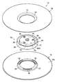
- FIG. 2 is an exploded perspective view showing the reel shown in FIG.
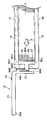
- FIG. 3 is a perspective view showing a longitudinal section along the axial direction of the reel shown in FIG.
- FIG. 4 is a plan view of the reel shown in FIG. 1 as viewed from the upper flange side.
- 5 is a cross-sectional view corresponding to the cross-sectional view taken along line 5-5 of FIG.
- FIG. 6 is a cross-sectional view corresponding to FIG. 5 showing the connecting portion in the second embodiment of the present invention.
- FIG. 7 is a cross-sectional view corresponding to FIG. 5 showing the connecting portion in the third embodiment of the present invention.
- FIG. 1 is a perspective view showing a state in which a reel according to the first embodiment of the present invention is incorporated in a drive device.
- FIG. 2 is an exploded perspective view showing the reel shown in
- FIG. 8 is a cross-sectional view corresponding to FIG. 5 and showing a coupling portion between the upper flange and the lower flange in the fourth embodiment of the present invention.
- FIG. 9A is a cross-sectional view corresponding to a partially enlarged view of FIG. 3 showing an analytical model of a reel according to the embodiment.
- FIG. 9B is a cross-sectional view corresponding to a partially enlarged view of FIG. 3 illustrating the reel analysis model according to the embodiment.
- FIG. 10 is a cross-sectional view corresponding to a partially enlarged view of FIG. 3 showing an analytical model of a reel according to a comparative example.
- FIG. 11 is a graph illustrating the analysis results of each analysis model according to the example and the comparative example.
- the arrow UP in FIG. 1 is the upward direction
- the arrow DO is the downward direction
- the rotation axis direction of the reels 10 and 20 according to this embodiment is the vertical direction (height direction).
- the pair of reels 10 and 20 according to the first embodiment are made of a synthetic resin such as polycarbonate (PC), for example, and as shown in FIG. 1, the casing 52 (the bottom plate 54 in FIG. 1) of the drive device 50 is used. And only three struts 56 are shown).
- PC polycarbonate
- the reel 10 is used for feeding out the recording tape T.
- the reel 20 is used for winding the recording tape T.
- the recording tape T fed from the reel 10 is slidably contacted with the recording / reproducing head 60 while being wound around the reel 20.
- the recording / reproducing head 60 records data on the recording tape T and reads data recorded on the recording tape T.
- a plurality of tape guides 58 are rotatably provided on the bottom plate 54 on both sides of the recording / reproducing head 60.
- the recording tape T drawn out from the reel 10 and taken up on the reel 20 is guided by each tape guide 58.
- Each of the reels 10 and 20 includes reel hubs 12 and 22 constituting an axial center portion, annular upper flanges 14 and 24 provided on the upper end side thereof, and annular lower flanges 16 and 26 provided on the lower end side thereof. It is comprised including.
- a recording tape T such as a magnetic tape as an information recording / reproducing medium is wound around the outer peripheral surface of the reel hub 12 in the reel 10.
- the recording tape T wound around the outer peripheral surface of the reel hub 12 is fed out toward the reel 20 while being guided by the upper flange 14 and the lower flange 16.
- the recording tape T fed out from the reel 10 is wound around the outer peripheral surface of the reel hub 22 of the reel 20 while being guided by the upper flange 24 and the lower flange 26 of the reel 20 that is rotationally driven in the same direction as the reel 10. .
- the reel hub 12 connects the hub body 70, the cylindrical winding part 80 provided on the outer periphery of the hub body 70, and the hub body 70 and the winding part 80. And a connecting portion 90.
- the hub main body portion 70 is provided on a cylindrical main body peripheral wall portion 72 that is arranged with the axial direction being the vertical direction, and an upper end portion of the main body peripheral wall portion 72. It has a disk-shaped lid (top wall) 74 that closes the opening at one axial end. Inside the main body peripheral wall portion 72, a housing portion S in which the motor 18 (see FIG. 5) serving as a drive source provided in the drive device 50 is housed is formed inside the main body peripheral wall portion 72. An opening 76 is formed at the lower end (the other end in the axial direction) of the main body peripheral wall portion 72. The motor 18 can be accommodated in the accommodating portion S through the opening 76.
- the lid portion 74 is not limited to the upper end portion of the main body peripheral wall portion 72 but can be provided on the upper end side of the main body peripheral wall portion 72.
- a boss portion 78 that protrudes from the upper surface and the lower surface of the lid portion 74 is formed at the center portion (rotation center portion) of the lid portion 74.
- the boss portion 78 is formed with a radial positioning hole 40 as a positioning portion that penetrates the boss portion 78 in the vertical direction.
- a radial positioning pin as a housing-side positioning portion (not shown) provided in the motor 18 into the radial positioning hole 40, the hub main body 70 is coaxial with the rotation shaft of the motor 18.
- the hub body 70 is disposed in the radial direction with respect to the rotation axis of the motor 18.
- the lower surface of the boss portion 78 is an axial positioning surface (axial reference surface) 78A as a positioning portion for positioning the reel 10 in the vertical direction (axial direction) with respect to the casing 52 of the drive device 50.
- the axial positioning surface 78A is brought into contact with an axial positioning surface as a housing side positioning portion (not shown) provided in the motor 18 in a state where the radial positioning pin described above is inserted into the radial positioning hole 40.
- the reel 10 is positioned in the vertical direction (axial direction) with respect to the casing 52 of the drive device 50.
- the lid portion 74 is formed with a plurality of (three in this embodiment) screw holes 36 penetrating the lid portion 74 in the plate thickness direction.
- the plurality of screw holes 36 are formed at equal intervals on the concentric circumference of the lid 74.
- the rotation of the motor 18 is performed by fastening a rotation flange (not shown) as a rotation member integrally provided on the rotation shaft of the motor 18 and the lid portion 74 with screws (not shown) inserted into the screw holes 36.
- the shaft and the hub main body 70 are rotatable together.
- a winding portion 80 around which the recording tape T (see FIG. 1) is wound around an outer peripheral surface (winding surface) 80 ⁇ / b> A is provided around the main body peripheral wall portion 72 of the hub main body portion 70. It has been.
- the winding part 80 is formed in a cylindrical shape, and is arranged with the axial direction as the vertical direction.
- a main body peripheral wall portion 72 of the hub main body portion 70 is disposed inside (inside) the winding portion 80.
- the winding portion 80 and the main body peripheral wall portion 72 are connected by a connecting portion 90.
- the cylinder shape in this embodiment is a concept including not only a strict cylindrical shape but also a substantially cylindrical shape formed in a cylindrical shape as a whole.
- the connecting portion 90 is formed in an annular shape as a whole.
- An inner peripheral surface 80 ⁇ / b> B of the winding portion 80 is coupled to the outer peripheral portion of the connecting portion 90.
- the outer peripheral surface 72 ⁇ / b> A of the main body peripheral wall 72 of the hub main body 70 is coupled to the inner peripheral portion of the connecting portion 90.
- the connecting portion 90 supports the winding portion 80 with respect to the main body peripheral wall portion 72.
- the connecting portion 90 includes an outer projecting portion 90 ⁇ / b> A that projects radially inward from the inner peripheral surface 80 ⁇ / b> B of the winding portion 80 and an outer peripheral surface 72 ⁇ / b> A of the main body peripheral wall portion 72 of the hub main body portion 70.
- a step part 90C as a deformation absorbing part connecting the outer projecting part 90A and the inner projecting part 90B.
- the outer projecting portion 90 ⁇ / b> A projects radially inward from the vertical central portion (vertical direction) on the inner peripheral surface 80 ⁇ / b> B of the winding portion 80. That is, the connecting portion 90 supports the central portion in the axial direction of the winding portion 80 with respect to the main body peripheral wall portion 72 of the hub main body portion 70.
- the upper surface and the lower surface of the outer projecting portion 90A are welding surfaces to which the pair of upper flange 14 and lower flange 16 are welded.
- a cylindrical lower cylindrical portion 17 extending upward is integrally formed on the inner peripheral edge of the lower flange 16.
- the lower cylindrical portion 17 is fitted into the winding portion 80 from the lower end of the winding portion 80.
- an overhang portion 35 that projects annularly toward the inside in the radial direction is integrally formed.
- ED energy directors
- the plurality of EDs 42 are projected in two rows with a predetermined interval in the circumferential direction of the overhang portion 35 and with a predetermined interval in the radial direction. Thereby, ultrasonic oscillation energy for melting the ED 42 is efficiently transmitted to each ED 42 while increasing the welding area.
- the upper surface of the overhanging portion 35 is moved outward by applying ultrasonic oscillation energy to each ED 42 and melting each ED 42. It is welded to the lower surface of the overhang portion 90A.
- the lower flange 16 protrudes radially outward from the lower end surface 80 ⁇ / b> L of the winding portion 80. It is supported by the hub body 70. Further, the upper surface 16U of the lower flange 16 is brought into contact with the lower end surface 80L of the winding portion 80, and the lower flange 16 is supported by the lower end surface 80L. Thereby, deformation of the winding part 80 and the lower flange 16 due to the winding pressure F of the recording tape T is suppressed.
- a cylindrical upper cylindrical portion 15 extending downward is integrally formed on the inner peripheral edge portion of the upper flange 14.
- the upper cylindrical portion 15 is fitted into the winding portion 80 from the upper end of the winding portion 80.
- a projecting portion 33 that projects annularly toward the inside in the radial direction is integrally formed at the lower end portion of the upper cylindrical portion 15.
- a plurality of EDs protrude from the lower surface of the overhang portion 33.
- the upper flange 14 is supported by the hub body portion 70 in a state of projecting radially outward from the upper end surface 80U of the winding portion 80. Yes.
- the lower surface 14L of the upper flange 14 is in contact with the upper end surface 80U of the winding portion 80, and the upper flange 14 is supported by the upper end surface 80U.
- transformation of the winding part 80 and the upper flange 14 by the winding pressure F of the recording tape T is suppressed.
- the upper flange 14 and the lower flange 16 have the same shape.
- the inner projecting part 90B is positioned on the opening 76 side (one axial direction side) of the hub main body part 70 (main body peripheral wall part 72) with respect to the outer projecting part 90A.
- a stepped portion 90C is formed.
- the step portion 90 ⁇ / b> C as a deformation absorbing portion is formed in a cylindrical shape, and extends downward from the inner peripheral portion of the hub main body portion 70 through the inside of the protruding portion 35 of the lower flange 16. That is, the stepped portion 90C extends to the opening 76 side of the hub main body 70 with respect to the outer overhanging portion 90A.
- the stepped portion 90 ⁇ / b> C is disposed at a distance from the main body peripheral wall portion 72 of the hub main body portion 70. Further, as shown in FIG. 4, the stepped portion 90 ⁇ / b> C extends in an annular shape along the outer peripheral surface 72 ⁇ / b> A of the main body peripheral wall portion 72.
- the outer peripheral part of the inner overhang part 90 ⁇ / b> B is connected to the lower end part of the step part 90 ⁇ / b> C.
- the inner projecting portion 90B is formed in an annular shape, and projects outward from the lower end portion (end portion on the opening 76 side) 72L of the main body peripheral wall portion 72 of the hub main body portion 70 in the radial direction. That is, the inner overhanging portion 90 ⁇ / b> B is connected to the main body peripheral wall portion 72 at a position shifted in the axial direction of the main body peripheral wall portion 72 with respect to the lid portion 74.
- the inwardly projecting portion 90B supports the stepped portion 90C so as to be tiltable toward the main body peripheral wall portion 72 side.
- an annular groove 92 is formed between the main body peripheral wall 72 and the step 90C. By this groove portion 92, a deformation space (tilt space) of the step portion 90C is secured.
- connecting portion (joining portion) 90D between the stepped portion 90C and the inner overhanging portion 90B is positioned below the lower end surface 80L of the winding portion 80, and the height (length) of the stepped portion 90C in the axial direction is long. L) L is increased.
- the accommodating portion S is formed inside the main body peripheral wall portion 72 of the hub main body portion 70.
- the casing 52 of the drive device 50 can be thinned.
- the housing portion S when the housing portion S is formed inside the hub main body 70, when the outer peripheral surface 80A of the winding portion 80 is pressed toward the main body peripheral wall 72 of the hub main body 70 by the winding pressure F of the recording tape T, The lid 74 of the hub main body 70 is easily curved and deformed so as to protrude upward as indicated by a two-dot chain line.
- the winding portion 80 is displaced downward with respect to the axial positioning surface 78A (see FIG. 3) provided on the boss portion 78 of the lid portion 74.
- the travel position of the recording tape T within the housing 52 of the drive device 50 and the winding deviation of the recording tape T with respect to the outer peripheral surface 80A of the winding unit 80 are likely to occur.
- the hub main body 70 is inclined with respect to the rotating shaft of the motor 18 (not shown), and recording in the housing 52 of the drive device 50 is performed as described above. There is a possibility that a change in the running position of the tape T and a winding deviation of the recording tape T with respect to the outer peripheral surface 80A of the winding portion 80 may occur.
- a stepped portion 90C is formed in the connecting portion 90 that connects the hub main body portion 70 and the winding portion 80. Due to the stepped portion 90C, the inner projecting portion 90B of the connecting portion 90 is positioned on the lower end portion 72L side of the main body peripheral wall portion 72 with respect to the outer projecting portion 90A. Therefore, when the outer peripheral surface 80A of the winding portion 80 is pressed toward the main body peripheral wall portion 72 by the winding pressure F of the recording tape T, the upper end portion of the stepped portion 90C is moved through the outer projecting portion 90A of the connecting portion 90. It is pressed toward the body peripheral wall 72 side.
- the stepped portion 90C moves toward the main body peripheral wall portion 72 side with the connecting portion 90D as a fulcrum as a fulcrum. It is elastically deformed so as to tilt, and the winding part 80 is displaced toward the main body peripheral wall part 72 side.
- transformation of the cover part 74 of the hub main-body part 70 is suppressed.
- the travel position change of the recording tape T within the housing 52 of the drive device 50 is suppressed, and the winding deviation of the recording tape T with respect to the outer peripheral surface 80A of the winding unit 80 is suppressed.
- each of the upper end surface 80U side and the lower end surface 80L side of the winding portion 80 is connected to the connecting portion.
- the outer projecting portion 90 ⁇ / b> A of 90 is bent toward the hub body 70 side.
- the outer projecting portion 90 ⁇ / b> A of the coupling portion 90 projects radially inward from the axial central portion of the winding portion 80. That is, the central part in the axial direction of the winding part 80 is supported by the hub body part 70 via the connecting part 90.
- each of the upper end face 80U side and the lower end face 80L side of the winding part 80 is The winding portion 80 bends toward the main body peripheral wall portion 72 with the axial center portion as a fulcrum.
- deviation of the deflection amount of the upper end surface 80U side and the lower end surface 80L side of the winding part 80 is reduced. Therefore, the winding deviation to the axial direction one side (upper or lower) of the winding part 80 of the recording tape T is suppressed.
- the inner projecting portion 90B of the connecting portion 90 projects outward in the radial direction from the lower end portion (end portion on the opening 76 side) 72L of the main body peripheral wall portion 72.
- the main body peripheral wall part 72 has the upper end part 72U (connection part with the lid part 74) as a fulcrum.
- the stepped portion 90C is elastically deformed as described above, the main body peripheral wall portion 72 has a moment (hereinafter referred to as the moment of tilting the main body peripheral wall portion 72 radially outward (winding portion 80 side) with the upper end 72U as a fulcrum.
- M 2 (referred to as “outer moment”). Since the inner moment M 1 is canceled by the outer moment M 2 , the deformation of the main body peripheral wall portion 72 in the radial direction is further suppressed.
- the inner projecting portion 90B projects outward from the lower end portion 72L of the main body peripheral wall portion 72 in the radial direction.
- the overall thickness of the reel 10 is reduced in the axial direction as compared with a configuration in which the inner overhanging portion 90B projects radially outward from a position shifted upward (from the lid 74 side) from the lower end 72L of the peripheral wall portion 72 of the main body.
- the height L in the axial direction of the main body peripheral wall portion 72 of the stepped portion 90C can be lengthened while achieving a reduction in size.
- the stepped portion 90C is easily elastically deformed toward the main body peripheral wall portion 72 side with the connecting portion 90D as a fulcrum. Therefore, the deformation of the main body peripheral wall portion 72 inward in the radial direction is further suppressed.
- the connecting portion 90D between the stepped portion 90C and the inner overhang portion 90B is located below the lower end surface 80L of the winding portion 80. Therefore, the height L in the axial direction of the stepped portion 90C is increased as compared with the configuration in which the connecting portion 90D between the stepped portion 90C and the inner projecting portion 90B is positioned above the lower end surface 80L of the winding portion 80. be able to.
- the moment acting on the step portion 90C is increased, so that the step portion 90C is It becomes easier to elastically deform toward the portion 72 side.
- the stepped portion 90 ⁇ / b> C extends in an annular shape along the outer peripheral surface 72 ⁇ / b> A of the main body peripheral wall portion 72 of the hub main body portion 70. Therefore, when the outer peripheral surface 80A of the winding portion 80 is pressed toward the main body peripheral wall portion 72 by the winding pressure F of the recording tape T, the stepped portion 90C is uniformly distributed over the entire circumference of the main body peripheral wall portion 72. Transforms into Therefore, deformation of the main body peripheral wall portion 72 inward in the radial direction is suppressed over the entire circumference of the main body peripheral wall portion 72.
- the upper flange 14 and the lower flange 16 have the same shape (vertical symmetry), only one mold for manufacturing the upper flange 14 and the lower flange 16 is sufficient. Therefore, the shape of the upper flange 14 and the lower flange 16 is different, and the manufacturing cost of the reel 10 can be reduced as compared with a configuration in which a mold for the upper flange 14 and a mold for the lower flange 16 are separately required. it can.
- the inner projecting portion 90B of the coupling portion 90 projects outward in the radial direction from the lower end portion 72L of the main body peripheral wall portion 72 of the hub main body portion 70 is shown, but the present invention is not limited thereto.
- the inner projecting portion 90B of the connecting portion 90 may be disposed at a position shifted in the vertical direction (axial direction) with respect to the outer projecting portion 90A of the connecting portion 90.
- the outer peripheral surface of the main body peripheral wall portion 72 The outer projecting portion 90 ⁇ / b> A in 72 ⁇ / b> A and the lower end portion 72 ⁇ / b> L of the main body peripheral wall portion 72 may project outward in the radial direction.
- the present invention is not limited thereto.
- the stepped portion 90C of the connecting portion 90 extends upward from the inner peripheral portion of the outer overhanging portion 90A, and the inner overhanging portion 90B moves upward ( You may position to the other side of an axial direction).
- the inner projecting portion 90B projects radially outward from the upper end side of the main body peripheral wall portion 72, and the outer peripheral portion thereof is connected to the upper end portion of the stepped portion 90C.
- the lower end portion of the stepped portion 90C is connected to the main body peripheral wall portion via the outer projecting portion 90A. 72 side.
- the pressing force pressing the lower end portion of the step portion 90C toward the main body peripheral wall portion 72 side becomes a predetermined value or more
- the step portion 90C moves toward the main body peripheral wall portion 72 side using the connection portion 90D with the inner overhang portion 90B as a fulcrum. It is elastically deformed so as to tilt, and the winding part 80 is displaced toward the main body peripheral wall part 72 side. Therefore, the same operation and effect as the first embodiment can be obtained.
- the inner projecting portion 90B is positioned on the lid 74 side of the hub main body 70 with respect to the outer projecting portion 90A, thereby simplifying the configuration of the lower end 72L side of the main body peripheral wall 72. Therefore, the reel 10 can be easily stored in the housing 52 of the drive device 50.
- the stepped portion 90C is formed in the connecting portion 90 that connects the hub main body portion 70 and the winding portion 80 is shown, but the present invention is not limited thereto.
- the recess 100 may be formed in the connecting portion 90 instead of the stepped portion 90 ⁇ / b> C.
- the inner projecting portion 90B projects radially outward from the axial central portion of the main body peripheral wall portion 72 of the hub main body portion 70, and is positioned on the radially inner side of the outer projecting portion 90A.
- the inner projecting portion 90B and the outer projecting portion 90A are connected by a recess 100.
- the concave portion 100 has a concave shape toward the opening 76 side of the hub main body portion 70 (main body peripheral wall portion 72) with respect to the inner projecting portion 90B and the outer projecting portion 90A.
- the concave portion 100 includes a pair of outer peripheral wall portions 100A and an inner peripheral wall portion 100B that face each other in the radial direction of the winding portion 80, and a bottom portion 100C that connects lower end portions of the outer peripheral wall portion 100A and the inner peripheral wall portion 100B.
- the outer peripheral wall portion 100A supports the connecting portion 100D with the bottom portion 100C as indicated by a two-dot chain line.
- the winding part 80 is displaced toward the main body peripheral wall part 72 side. Therefore, the same operation and effect as the first embodiment can be obtained.
- the concave portion 100 forms a concave shape toward the opening 76 side of the hub main body portion 70 with respect to the inner overhang portion 90B and the outer overhang portion 90A
- a recess may be formed on the inner projecting portion 90 ⁇ / b> B and the outer projecting portion 90 ⁇ / b> A so as to form a concave shape toward the lid portion 74 side of the hub body 70.
- the inner overhang 90B is positioned on the radially inner side of the outer overhang 90A.
- the inner overhang 90B is positioned in the vertical direction with respect to the outer overhang 90A ( It may be arranged at a position shifted in the axial direction.
- the step portion 90C in the first and second embodiments is disposed between the winding portion 80 and the main body peripheral wall portion 72 with the axial direction of the main body peripheral wall portion 72 as the longitudinal direction, and an upper end portion (one end in the longitudinal direction). Side) is connected to the winding portion 80 via the outer overhanging portion 90A, and the lower end portion (the other end in the longitudinal direction) is connected to the main body peripheral wall portion 72 via the inner overhanging portion 90B. Corresponds to the shape.
- the outer projecting portion 90A of the connecting portion 90 projects from the central portion in the axial direction of the winding portion 80 to the inner side in the radial direction is shown, but the present invention is not limited to this.
- the outer projecting portion 90 ⁇ / b> A may project radially inward from a portion shifted in the vertical direction (axial direction) from the axial central portion of the winding unit 80.
- the example in which the radial positioning hole 40 and the axial positioning surface 78A as the positioning portion are formed in the boss portion 78 of the lid portion 74 of the hub main body portion 70 is shown. Not limited to this.
- the positions and shapes of the radial positioning hole 40 and the axial positioning surface 78A can be changed as appropriate. Further, at least one of the radial positioning hole 40 and the axial positioning surface 78A may be formed in the lid 74.
- the present invention is not limited to this.
- the accommodating portion S can accommodate rotational driving parts for rotating the reel 10 and various wirings.
- the through hole 30 is formed in the outer projecting portion 90 ⁇ / b> A of the connecting portion 90 ⁇ / b> A.
- protrusions 46 and 48 as insertion portions inserted into the through holes 30 are formed, respectively. These protrusions 46 and 48 are inserted into the through hole 30 from opposite directions.
- a screw boss 66 formed in the protrusion 48 is fitted in the fitting hole 64 formed in the protrusion 46.
- a screw hole 49 communicating with the fitting hole 64 is formed in the overhang portion 33.
- the reel hub is formed by directly connecting the projecting portion 33 of the upper flange 14 and the projecting portion 35 of the lower flange 16 through the through hole 30 formed in the outer projecting portion 90A of the connecting portion 90. 12, the upper flange 14 and the lower flange 16 can be attached so as not to rotate relative to each other. Accordingly, it is not necessary to separately form a detent means for making the upper flange 14 and the lower flange 16 non-rotatable relative to the reel hub 12 in the reel hub 12, the upper flange 14, the lower flange 16, and the like.
- the structure of the mold for forming the reel hub 12, the upper flange 14, and the lower flange 16 can be simplified as compared with the configuration in which the rotation preventing means is formed on the reel hub 12, the upper flange 14, the lower flange 16, and the like. Can do. Therefore, the manufacturing cost of molds and the like can be reduced.
- the overhanging portion 33 of the upper flange 14 and the overhanging portion 35 of the lower flange 16 are coupled with the screws 62 is shown, but the present invention is not limited thereto.
- the overhang portion 33 of the upper flange 14 and the overhang portion 35 of the lower flange 16 may be welded using ED or the like.
- the reel 10 is arranged with the rotation axis direction as the vertical direction, but the present invention is not limited to this.
- the reel 10 may be arranged with the rotation axis direction as the horizontal direction.
- the reels 10 and 20 according to the above embodiment can be applied to a recording tape cartridge in which only one reel is accommodated in the housing 52.
- FIG. 9A shows a basic model of the analysis model according to the first to fifth embodiments.
- FIG. 9B shows an analysis model according to the sixth embodiment.
- Examples 1 to 5 are analysis models corresponding to the reel 10 shown in FIG. 5, and Example 6 is an analysis model corresponding to a first modification of the reel 10 shown in FIG.
- Table 1 the height L (see FIG. 5) of the stepped portion 90C is different.
- Table 1 the height L of the stepped portion 90 ⁇ / b> C is expressed with the lower side being positive with respect to the central portion in the axial direction of the winding portion 80.
- FIG. 10 shows an analysis model according to a comparative example.
- the stepped portion is not formed in the connecting portion 90, and the lower end portion 72 ⁇ / b> L of the main body peripheral wall portion 72 of the hub main body portion 70 and the axially central portion of the winding portion 80 are formed by the flat connecting portion 110. Are connected.
- an equally distributed load that simulates the winding pressure F of the recording tape is applied to the outer peripheral surface 80A of the winding part 80.
- the amount of deformation dy (a) in the vertical direction (axial direction) of the outer peripheral edge 74A of the lid part 74 in each analysis model, and the vertical direction (axis) of the inner peripheral edge in the upper end surface 80U of the winding part 80 Direction) deformation dy (b) was obtained by analysis.
- the support condition for the axial positioning surface 78A is fixed.
- the analysis results are shown in Table 1 and FIG.
- the deformation amount dy (a) of the outer peripheral edge 74A of the lid portion 74 and the deformation amount dy (b) of the upper end surface 80U of the winding portion 80 are the outer peripheral edge 74A of the lid portion 74 and the upper end surface 80U of the winding portion 80.
- the position of the inner peripheral edge before deformation is expressed as a reference with the lower part being positive and the upper part being negative.
- the absolute value of the deformation amount dy (b) of the upper end surface 80U of the winding portion 80 is smaller than that of the analysis model according to the comparative example.
- the stepped portion 90C is elastically deformed and the winding portion 80 is displaced toward the hub main body 70, so that the upper end surface 80U side of the winding portion 80 is located. This is thought to be due to the absorption of the bending deformation.
- the deformation amount dy (a) of the outer peripheral edge 74A of the lid portion 74 and the winding amount are increased.
- the absolute value of the deformation amount dy (b) of the upper end surface 80U of the portion 80 is small. Therefore, by suppressing the height L of the stepped portion 90C, the effect of suppressing the deformation of the lid portion 74 and the winding portion 80 of the hub main body portion 70 can be improved.
Landscapes
- Storage Of Web-Like Or Filamentary Materials (AREA)
Abstract
A reel (10) is equipped with a hub body (70), and a winding part (80) having a recording tape (T) wound around the outer-circumferential surface (80A) thereof. The hub body (70) has a body-peripheral-wall section (72) formed in a cylindrical shape, and a lid section (74) positioned on the top end of the body-peripheral-wall section (72). The winding part (80) is formed in a cylindrical shape, and has the body-peripheral-wall section (72) positioned in the interior thereof. The inner-circumferential surface (80B) of the winding part (80) and the outer-circumferential surface (72A) of the body-peripheral-wall section (72) are connected by a connecting section (90) that projects toward the inside in the radial direction from the inner-circumferential surface (80B) of the winding part (80). The connecting section (90) has a step section (90C) formed therein for deforming the winding part (80) toward the body-peripheral-wall section (72) side by elastic deformation.
Description
本発明は、磁気テープ等の記録テープが巻装されるリールに関する。
The present invention relates to a reel on which a recording tape such as a magnetic tape is wound.
一対の上フランジ板及び下フランジ板と、下フランジ板に一体に形成されたリールハブとを備えたリールハブが知られている(例えば、特開平10-199195号公報参照)。
A reel hub including a pair of upper flange plate and lower flange plate and a reel hub formed integrally with the lower flange plate is known (see, for example, JP-A-10-199195).
特開平10-199195号公報に開示されたリールハブは、回転軸が挿入されるハブ孔が形成された中心部と、磁気テープが巻回される筒状の巻装部と、中心部と巻装部とを連結する補強リブとを有している。
A reel hub disclosed in Japanese Patent Application Laid-Open No. 10-199195 includes a central part in which a hub hole into which a rotating shaft is inserted is formed, a cylindrical winding part around which a magnetic tape is wound, a central part and a winding part. And reinforcing ribs that connect the parts.
また、特開平10-199195号公報に開示された下フランジ板には、巻装部の外周面に沿った環状の変形吸収溝が形成されている。この変形吸収溝によって、磁気テープの巻き圧により中心部側へ傾倒する巻装部の弾性変形を吸収することにより、下フランジ板の変形が抑制されている。
Further, the lower flange plate disclosed in Japanese Patent Laid-Open No. 10-199195 is formed with an annular deformation absorbing groove along the outer peripheral surface of the winding portion. By this deformation absorbing groove, the deformation of the lower flange plate is suppressed by absorbing the elastic deformation of the wound portion that tilts toward the center due to the winding pressure of the magnetic tape.
しかしながら、特開平10-199195号公報に開示されたリールハブでは、磁気テープの巻き圧によって巻装部が中心部側へ傾倒すると、補強リブを介して中心部が径方向内側へ押圧される。これにより、リールハブの中心部の天壁部が変形すると、当該天壁部と巻装部との相対位置が巻装部の軸方向へずれる可能性がある。換言すると、リールハブの中心部の天壁部が変形すると、リールハブ全体が軸方向へずれる可能性がある。この結果、巻回部へ供給される磁気テープに対して巻回部が軸方向へ変位し、ドライブ内での磁気テープの走行位置変化や巻きずれの原因となる。
However, in the reel hub disclosed in Japanese Patent Laid-Open No. 10-199195, when the winding part is tilted toward the center part by the winding pressure of the magnetic tape, the center part is pressed radially inward via the reinforcing rib. Thereby, if the top wall part of the center part of a reel hub deform | transforms, the relative position of the said ceiling wall part and a winding part may shift | deviate to the axial direction of a winding part. In other words, if the top wall portion at the center of the reel hub is deformed, the entire reel hub may be displaced in the axial direction. As a result, the winding portion is displaced in the axial direction with respect to the magnetic tape supplied to the winding portion, causing a change in the traveling position of the magnetic tape in the drive and a winding deviation.
本発明は、上記の事実を考慮し、ハブ本体部の蓋部と巻回部との相対位置が巻回部の軸方向へずれることを抑制することができるリールを得ることを目的とする。
The present invention has been made in consideration of the above facts, and an object of the present invention is to obtain a reel capable of suppressing the relative position between the lid portion of the hub main body portion and the winding portion from shifting in the axial direction of the winding portion.
本発明の第1の態様に係るリールは、筒状に形成された本体周壁部と該本体周壁部の軸方向一端側に設けられた蓋部とを有するハブ本体部と、筒状に形成され、内部に前記本体周壁部が配置されると共に外周面に記録テープが巻回される巻回部と、前記巻回部の内周面から径方向内側へ張り出し、該巻回部と前記本体周壁部の外周面とを連結する連結部と、前記連結部に形成され、弾性変形することにより前記巻回部を前記本体周壁部側へ変位させる変形吸収部と、を備えている。
A reel according to a first aspect of the present invention is formed in a cylindrical shape, a hub main body portion having a cylindrical main body peripheral wall portion and a lid portion provided on one end side in the axial direction of the main peripheral wall portion. A winding portion in which the main body peripheral wall portion is disposed and a recording tape is wound around an outer peripheral surface, and projects radially inward from an inner peripheral surface of the winding portion, and the winding portion and the main body peripheral wall A connecting part that connects the outer peripheral surface of the part, and a deformation absorbing part that is formed in the connecting part and that is elastically deformed to displace the winding part toward the peripheral wall part of the main body.
上記第1の態様に係るリールによれば、所定値以上の記録テープの巻き圧によって巻回部の外周面がハブ本体部の本体周壁部側へ押圧されたときに、連結部に形成された変形吸収部が弾性変形し、当該巻回部が本体周壁部側へ変位する。これにより、本体周壁部の径方向内側への変形が抑制されるため、ハブ本体部の蓋部の変形が抑制される。この結果、蓋部と巻回部との相対位置が巻回部の軸方向へずれることが抑制される。したがって、記録テープの走行位置変化が抑制されると共に、巻回部の外周面に対する記録テープの巻きずれが抑制される。
According to the reel according to the first aspect, when the outer peripheral surface of the winding part is pressed toward the main body peripheral wall part side of the hub main body part by the winding pressure of the recording tape of a predetermined value or more, it is formed in the connecting part. The deformation absorbing portion is elastically deformed, and the winding portion is displaced toward the main body peripheral wall portion. Thereby, since a deformation | transformation to the radial inside of a main body surrounding wall part is suppressed, a deformation | transformation of the cover part of a hub main-body part is suppressed. As a result, the relative position between the lid portion and the winding portion is suppressed from shifting in the axial direction of the winding portion. Therefore, the running position change of the recording tape is suppressed, and the winding deviation of the recording tape with respect to the outer peripheral surface of the winding portion is suppressed.
本発明の第2の態様に係るリールは、上記第1の態様に係るリールにおいて、前記連結部が、前記蓋部に対して前記本体周壁部の軸方向にずれた位置で該本体周壁部と連結されている。
A reel according to a second aspect of the present invention is the reel according to the first aspect, wherein the connecting portion is located at a position shifted in the axial direction of the main body peripheral wall portion with respect to the lid portion. It is connected.
上記第2の態様に係るリールによれば、連結部が、蓋部に対して本体周壁部の軸方向にずれて位置で当該本体周壁部と連結されている。そのため、本体周壁部には、蓋部に対して本体周壁部の軸方向にずれた位置に連結部を介して記録テープの巻き圧が入力される。これにより、連結部が、蓋部に対して本体周壁部の軸方向にずれない位置で当該本体周壁部と連結された比較して、本体周壁部が変形し易くなる結果、蓋部が変形し易くなる。このように蓋部が変形し易くなる構成に、本発明は特に有効である。
According to the reel according to the second aspect, the connecting portion is connected to the main body peripheral wall portion at a position shifted in the axial direction of the main body peripheral wall portion with respect to the lid portion. Therefore, the winding pressure of the recording tape is input to the main body peripheral wall portion via the connecting portion at a position shifted in the axial direction of the main body peripheral wall portion with respect to the lid portion. As a result, compared to the connecting portion connected to the main body peripheral wall portion at a position that does not shift in the axial direction of the main body peripheral wall portion with respect to the lid portion, the main body peripheral wall portion is likely to be deformed. It becomes easy. The present invention is particularly effective for such a configuration in which the lid portion is easily deformed.
本発明の第3の態様に係るリールは、上記第1の態様又は上記第2の態様に係るリールにおいて、前記連結部が、前記巻回部の内周面から径方向内側へ張り出す外側張出部と、前記本体周壁部の外周面から径方向外側へ張り出す内側張出部と、を有し、前記変形吸収部が、前記外側張出部に対して前記内側張出部を前記本体周壁部の軸方向一方側へ位置させる段差部である。
A reel according to a third aspect of the present invention is the reel according to the first aspect or the second aspect, wherein the connecting portion is an outer tension projecting radially inward from the inner peripheral surface of the winding portion. A projecting portion, and an inner projecting portion projecting radially outward from an outer peripheral surface of the main body peripheral wall portion, and the deformation absorbing portion places the inner projecting portion with respect to the outer projecting portion. It is a level | step-difference part located in the axial direction one side of a surrounding wall part.
上記第3の態様に係るリールによれば、所定値以上の記録テープの巻き圧によって巻回部の外周面が本体周壁部側へ押圧されたときに、連結部に形成された段差部が弾性変形することにより、当該巻回部が本体周壁部側へ変位する。これにより、本体周壁部の径方向内側への変形が抑制されるため、ハブ本体部の蓋部の変形が抑制される。この結果、蓋部と巻回部との相対位置が巻回部の軸方向へずれることが抑制される。
According to the reel of the third aspect, when the outer peripheral surface of the winding part is pressed toward the main body peripheral wall part by the winding pressure of the recording tape of a predetermined value or more, the step part formed in the connecting part is elastic. By deform | transforming, the said winding part displaces to the main body surrounding wall part side. Thereby, since a deformation | transformation to the radial inside of a main body surrounding wall part is suppressed, a deformation | transformation of the cover part of a hub main-body part is suppressed. As a result, the relative position between the lid portion and the winding portion is suppressed from shifting in the axial direction of the winding portion.
本発明の第4の態様に係るリールは、上記第3の態様に係るリールにおいて、前記段差部が、前記外側張出部に対して前記内側張出部を前記本体周壁部の開口側に位置させる。
The reel according to a fourth aspect of the present invention is the reel according to the third aspect, wherein the stepped portion is located on the opening side of the main body peripheral wall portion with respect to the outer overhang portion. Let
上記第4の態様に係るリールによれば、段差部によって連結部の内側張出部が外側張出部に対して本体周壁部の開口側に位置されている。これにより、所定値以上の記録テープの巻き圧によって巻回部の外周面が本体周壁部側へ押圧されたときに、段差部が本体周壁部の開口側に位置する内側張出部との接続部を支点として本体周壁部側へ傾倒するように弾性変形する。
According to the reel of the fourth aspect, the inner projecting portion of the connecting portion is located on the opening side of the peripheral wall portion with respect to the outer projecting portion by the step portion. Thereby, when the outer peripheral surface of the winding part is pressed toward the main body peripheral wall by the winding pressure of the recording tape of a predetermined value or more, the stepped part is connected to the inner overhanging part located on the opening side of the main peripheral wall. It is elastically deformed so as to tilt toward the main body peripheral wall with the portion as a fulcrum.
ここで、巻回部が連結部を介して本体周壁部を径方向内側へ押圧すると、本体周壁部には、蓋部との接続部を支点として当該本体周壁部を径方向内側へ傾倒させるモーメント(以下、「内側モーメント」という)が作用する。一方、段差部が前述のように弾性変形すると、本体周壁部には、蓋部との接続部を支点として当該本体周壁部を径方向外側(巻回部側)へ傾倒させるモーメント(以下、「外側モーメント」という)が作用する。この外側モーメントによって内側モーメントが打ち消されるため、本体周壁部の径方向内側への変形がさらに抑制される。
Here, when the winding portion presses the main body peripheral wall portion inward in the radial direction via the connecting portion, the main body peripheral wall portion has a moment that tilts the main body peripheral wall portion inward in the radial direction with the connection portion with the lid portion as a fulcrum. (Hereinafter referred to as “inner moment”). On the other hand, when the stepped portion is elastically deformed as described above, a moment (hereinafter referred to as “the side of the winding portion”) is tilted to the outer peripheral wall portion of the main body peripheral wall portion with the connecting portion with the lid portion as a fulcrum. Acts as "outer moment". Since the inner moment is canceled by this outer moment, the deformation of the main body peripheral wall portion toward the inner side in the radial direction is further suppressed.
本発明の第5の態様に係るリールは、上記第4の態様に係るリールにおいて、前記内側張出部が、前記本体周壁部の開口側端部から径方向外側へ張り出している。
In the reel according to the fifth aspect of the present invention, in the reel according to the fourth aspect, the inner overhanging portion protrudes radially outward from the opening-side end portion of the peripheral wall portion of the main body.
上記第5の態様に係るリールによれば、内側張出部が、本体周壁部の開口側端部から径方向外側に張り出している。そのため、内側張出部が本体周壁部の開口側端部から蓋部側へずれた位置から径方向外側へ張り出した構成と比較して、リール全体の軸方向の薄型化を図りつつ、段差部の本体周壁部の軸方向の長さを長くすることができる。これにより、段差部が内側張出部との接続部を支点として本体周壁部側へ弾性変形し易くなるため、本体周壁部の径方向内側への変形がさらに抑制される。
According to the reel of the fifth aspect, the inner projecting portion projects outward in the radial direction from the opening-side end portion of the peripheral wall portion of the main body. Therefore, compared with the configuration in which the inner overhanging portion projects radially outward from the position where the inner overhanging portion is shifted from the opening side end portion of the main body peripheral wall portion to the lid side, the step portion is made thin in the axial direction of the entire reel. The axial length of the peripheral wall portion of the main body can be increased. As a result, the stepped portion is easily elastically deformed toward the main body peripheral wall portion with the connecting portion with the inner overhanging portion as a fulcrum, so that deformation of the main body peripheral wall portion in the radial direction is further suppressed.
本発明の第6の態様に係るリールは、上記第3の態様に係るリールにおいて、前記段差部が、前記外側張出部に対して前記内側張出部を前記蓋部側に位置させる。
In the reel according to the sixth aspect of the present invention, in the reel according to the third aspect, the stepped portion positions the inner overhanging portion on the lid portion side with respect to the outer overhanging portion.
上記第6の態様に係るリールによれば、段差部によって連結部の内側張出部を外側張出部に対してハブ本体部の蓋部側に位置させたことにより、本体周壁部の開口側の構成が単純化される。
According to the reel of the sixth aspect, the inner projecting portion of the connecting portion is positioned on the lid portion side of the hub main body portion with respect to the outer projecting portion by the stepped portion, so that the opening side of the peripheral wall portion of the main body The configuration of is simplified.
本発明の第7の態様に係るリールは、上記第1の態様又は上記第2の態様に係るリールにおいて、前記連結部が、前記巻回部の内周面から径方向内側へ張り出す外側張出部と、前記本体周壁部の外周面から径方向外側へ張り出す内側張出部と、を有し、前記変形吸収部が、前記巻回部と前記本体周壁部との間に該本体周壁部の軸方向を長手方向として配置され、長手方向一端側が前記外側張出部を介して前記巻回部に連結されると共に長手方向他端側が前記内側張出部を介して前記本体周壁部に連結された壁状部である。
A reel according to a seventh aspect of the present invention is the reel according to the first aspect or the second aspect, wherein the connecting portion is an outer tension projecting radially inward from the inner peripheral surface of the winding portion. A projecting portion and an inner projecting portion projecting radially outward from the outer peripheral surface of the main body peripheral wall portion, and the deformation absorbing portion is interposed between the winding portion and the main body peripheral wall portion. An axial direction of the portion is disposed as a longitudinal direction, one end in the longitudinal direction is connected to the winding portion via the outer overhanging portion, and the other end in the longitudinal direction is connected to the peripheral wall portion of the main body via the inner overhanging portion. It is the connected wall-like part.
上記第7の態様に係るリールによれば、所定値以上の記録テープの巻き圧によって巻回部の外周面が本体周壁部側へ押圧されたときに、連結部に形成された壁状部が弾性変形することにより、当該巻回部が本体周壁部側へ変位する。これにより、本体周壁部の径方向内側への変形が抑制されるため、ハブ本体部の蓋部の変形が抑制される。この結果、蓋部と巻回部との相対位置が巻回部の軸方向へずれることが抑制される。
According to the reel according to the seventh aspect, when the outer peripheral surface of the winding portion is pressed toward the main body peripheral wall portion by the winding pressure of the recording tape equal to or greater than a predetermined value, the wall-shaped portion formed in the connecting portion is By elastically deforming, the winding part is displaced toward the main body peripheral wall part. Thereby, since a deformation | transformation to the radial inside of a main body surrounding wall part is suppressed, a deformation | transformation of the cover part of a hub main-body part is suppressed. As a result, the relative position between the lid portion and the winding portion is suppressed from shifting in the axial direction of the winding portion.
本発明の第8の態様に係るリールは、上記第3の態様~上記第7の態様の何れか1つに係るリールにおいて、前記外側張出部が、前記巻回部の軸方向中央部から径方向内側へ張り出している。
A reel according to an eighth aspect of the present invention is the reel according to any one of the third to seventh aspects, wherein the outer overhanging portion extends from an axially central portion of the winding portion. Projects radially inward.
上記第8の態様に係るリールによれば、連結部の外側張出部が、巻回部の軸方向中央部から径方向内側へ張り出している。つまり、巻回部の軸方向中央部が、連結部を介して本体周壁部に支持されている。これにより、記録テープの巻き圧によって巻回部の外周面が本体周壁部側へ押圧されたときに、巻回部の軸方向両端側の各々が当該巻回部の軸方向中央部を支点として本体周壁部側へ撓むため、巻回部の軸方向両端側の撓み量の偏りが低減される。したがって、記録テープの巻回部の軸方向一方側への巻きずれが抑制される。
According to the reel according to the eighth aspect, the outer projecting portion of the connecting portion projects radially inward from the axial central portion of the winding portion. That is, the axial center part of the winding part is supported by the main body peripheral wall part via the connecting part. Thereby, when the outer peripheral surface of the winding part is pressed to the main body peripheral wall part side by the winding pressure of the recording tape, each of both ends in the axial direction of the winding part has the axial center part of the winding part as a fulcrum. Since the main body is bent toward the peripheral wall, the deviation of the amount of bending at both ends in the axial direction of the winding portion is reduced. Therefore, the winding shift | offset | difference to the axial direction one side of the winding part of a recording tape is suppressed.
本発明の第9の態様に係るリールは、上記第3の態様~上記第8の態様の何れか1つに係るリールにおいて、前記段差部が、前記本体周壁部の外周面に沿って環状に延びている。
The reel according to a ninth aspect of the present invention is the reel according to any one of the third to eighth aspects, wherein the stepped portion is annular along the outer peripheral surface of the main body peripheral wall portion. It extends.
上記第9の態様に係るリールによれば、段差部が本体周壁部の外周面に沿って環状に延びているため、本体周壁部の全周にわたって本体周壁部の径方向内側への変形が抑制される。
According to the reel according to the ninth aspect, since the step portion extends in an annular shape along the outer peripheral surface of the main body peripheral wall portion, the deformation of the main body peripheral wall portion toward the radially inner side is suppressed over the entire circumference of the main body peripheral wall portion. Is done.
本発明の第10の態様に係るリールは、上記第1の態様~上記第9の態様の何れか1つに係るリールにおいて、前記蓋部には、前記ハブ本体部を該ハブ本体部が収納される筐体に対して位置決めする位置決め部が形成されている。
A reel according to a tenth aspect of the present invention is the reel according to any one of the first aspect to the ninth aspect, wherein the hub main body portion houses the hub main body portion in the lid portion. A positioning portion for positioning with respect to the casing to be formed is formed.
上記第10の態様に係るリールによれば、ハブ本体部を筐体に対して位置決めする位置決め部が蓋部に形成されている。したがって、蓋部の変形を抑制することにより、筐体に対するハブ本体部の位置ずれが抑制される。
According to the reel of the tenth aspect, the positioning part for positioning the hub main body part with respect to the housing is formed on the lid part. Accordingly, by suppressing the deformation of the lid portion, the positional deviation of the hub body portion with respect to the housing is suppressed.
本発明の第11の態様に係るリールは、上記第1の態様~上記第10の態様の何れか1つに係るリールにおいて、前記本体周壁部の内部には、前記ハブ本体部を回転駆動するモータを収容する収容部が形成されている。
A reel according to an eleventh aspect of the present invention is the reel according to any one of the first aspect to the tenth aspect described above, wherein the hub main body portion is rotationally driven inside the main body peripheral wall portion. A housing portion for housing the motor is formed.
上記第11の態様に係るリールによれば、ハブ本体部の本体周壁部の内部に形成された収容部に当該ハブ本体部を回転駆動するモータを収容することにより、リールが収納される筐体等の薄型化を図ることができる。
According to the reel according to the eleventh aspect, the housing in which the reel is housed by housing the motor that rotationally drives the hub body in the housing formed inside the body peripheral wall of the hub body. Etc. can be reduced in thickness.
以上説明したように、本発明に係るリールによれば、ハブ本体部の蓋部と巻回部との相対位置が巻回部の軸方向へずれることを抑制することができる。
As described above, according to the reel of the present invention, it is possible to suppress the relative position between the lid portion of the hub main body portion and the winding portion from shifting in the axial direction of the winding portion.
以下、図面を参照しながら、本発明の実施形態に係るリールについて説明する。なお、説明の便宜上、図1における矢印UPを上方向、矢印DOを下方向とし、本実施形態に係るリール10,20の回転軸方向を上下方向(高さ方向)とする。
Hereinafter, a reel according to an embodiment of the present invention will be described with reference to the drawings. For convenience of explanation, the arrow UP in FIG. 1 is the upward direction, the arrow DO is the downward direction, and the rotation axis direction of the reels 10 and 20 according to this embodiment is the vertical direction (height direction).
先ず、第1実施形態について説明する。
First, the first embodiment will be described.
第1実施形態に係る一対のリール10,20は、例えばポリカーボネート(PC)等の合成樹脂製とされており、図1に示されるように、ドライブ装置50の筐体52(図1では底板54と3本の支柱56のみが示されている)内に収納されている。
The pair of reels 10 and 20 according to the first embodiment are made of a synthetic resin such as polycarbonate (PC), for example, and as shown in FIG. 1, the casing 52 (the bottom plate 54 in FIG. 1) of the drive device 50 is used. And only three struts 56 are shown).
リール10は、記録テープTの繰り出し用とされている。一方、リール20は、記録テープTの巻き取り用とされている。そして、リール10から繰り出された記録テープTが、リール20に巻き取られつつ、記録再生ヘッド60に摺接するようになっている。この記録再生ヘッド60によって、記録テープTに対してデータが記録されたり、記録テープTに記録されたデータが読み取られる。
The reel 10 is used for feeding out the recording tape T. On the other hand, the reel 20 is used for winding the recording tape T. The recording tape T fed from the reel 10 is slidably contacted with the recording / reproducing head 60 while being wound around the reel 20. The recording / reproducing head 60 records data on the recording tape T and reads data recorded on the recording tape T.
なお、記録再生ヘッド60の両側における底板54には、複数個(図示のものは2個ずつで計4個)のテープガイド58が回転自在に設けられている。そして、リール10から引き出されてリール20に巻き取られる記録テープTが、各テープガイド58によってガイドされるようになっている。
Note that a plurality of tape guides 58 (two in the figure, four in total) are rotatably provided on the bottom plate 54 on both sides of the recording / reproducing head 60. The recording tape T drawn out from the reel 10 and taken up on the reel 20 is guided by each tape guide 58.
また、各リール10,20は、軸心部を構成するリールハブ12,22と、その上端側に設けられる環状の上フランジ14,24と、その下端側に設けられる環状の下フランジ16,26とを含んで構成されている。
Each of the reels 10 and 20 includes reel hubs 12 and 22 constituting an axial center portion, annular upper flanges 14 and 24 provided on the upper end side thereof, and annular lower flanges 16 and 26 provided on the lower end side thereof. It is comprised including.
リール10におけるリールハブ12の外周面には、情報記録再生媒体としての磁気テープ等の記録テープTが巻回されている。このリール10が所定方向に回転駆動されると、リールハブ12の外周面に巻回された記録テープTが上フランジ14及び下フランジ16によってガイドされながらリール20へ向けて繰り出される。リール10から繰り出された記録テープTは、リール10と同方向に回転駆動されたリール20の上フランジ24及び下フランジ26によってガイドされながら、当該リール20におけるリールハブ22の外周面に巻回される。
A recording tape T such as a magnetic tape as an information recording / reproducing medium is wound around the outer peripheral surface of the reel hub 12 in the reel 10. When the reel 10 is rotationally driven in a predetermined direction, the recording tape T wound around the outer peripheral surface of the reel hub 12 is fed out toward the reel 20 while being guided by the upper flange 14 and the lower flange 16. The recording tape T fed out from the reel 10 is wound around the outer peripheral surface of the reel hub 22 of the reel 20 while being guided by the upper flange 24 and the lower flange 26 of the reel 20 that is rotationally driven in the same direction as the reel 10. .
なお、リール10とリール20の構成は同一であるため、以下ではリール10を例に採って説明し、リール20の説明は省略する。図2に示されるように、リールハブ12は、ハブ本体部70と、ハブ本体部70の外周に設けられた筒状の巻回部80と、ハブ本体部70と巻回部80とを連結する連結部90とを有している。
Since the reel 10 and the reel 20 have the same configuration, the reel 10 will be described below as an example, and the description of the reel 20 will be omitted. As shown in FIG. 2, the reel hub 12 connects the hub body 70, the cylindrical winding part 80 provided on the outer periphery of the hub body 70, and the hub body 70 and the winding part 80. And a connecting portion 90.
図3に示されるように、ハブ本体部70は、軸方向を上下方向として配置された筒状の本体周壁部72と、本体周壁部72の上端部に設けられ、本体周壁部72の上端側(軸方向一端側)の開口を閉じる円盤状の蓋部(天壁部)74とを有している。本体周壁部72の内部には、ドライブ装置50に設けられた駆動源としてのモータ18(図5参照)が収容される収容部Sが形成されている。また、本体周壁部72の下端(軸方向他端)には、開口76が形成されている。この開口76から、モータ18が収容部Sへ収容可能になっている。なお、蓋部74は、本体周壁部72の上端部に限らず、本体周壁部72の上端側に設けることも可能である。
As shown in FIG. 3, the hub main body portion 70 is provided on a cylindrical main body peripheral wall portion 72 that is arranged with the axial direction being the vertical direction, and an upper end portion of the main body peripheral wall portion 72. It has a disk-shaped lid (top wall) 74 that closes the opening at one axial end. Inside the main body peripheral wall portion 72, a housing portion S in which the motor 18 (see FIG. 5) serving as a drive source provided in the drive device 50 is housed is formed. An opening 76 is formed at the lower end (the other end in the axial direction) of the main body peripheral wall portion 72. The motor 18 can be accommodated in the accommodating portion S through the opening 76. The lid portion 74 is not limited to the upper end portion of the main body peripheral wall portion 72 but can be provided on the upper end side of the main body peripheral wall portion 72.
蓋部74の中心部(回転中心部)には、当該蓋部74の上面及び下面からそれぞれ突出するボス部78が形成されている。ボス部78には、当該ボス部78を上下方向に貫通する位置決め部としての径方向位置決め孔40が形成されている。この径方向位置決め孔40に、モータ18に設けられた図示しない筐体側位置決め部としての径方向位置決めピンを挿入(嵌合)することにより、モータ18の回転軸と同軸上にハブ本体部70が配置され、当該モータ18の回転軸に対してハブ本体部70が径方向に位置決められる。
A boss portion 78 that protrudes from the upper surface and the lower surface of the lid portion 74 is formed at the center portion (rotation center portion) of the lid portion 74. The boss portion 78 is formed with a radial positioning hole 40 as a positioning portion that penetrates the boss portion 78 in the vertical direction. By inserting (fitting) a radial positioning pin as a housing-side positioning portion (not shown) provided in the motor 18 into the radial positioning hole 40, the hub main body 70 is coaxial with the rotation shaft of the motor 18. The hub body 70 is disposed in the radial direction with respect to the rotation axis of the motor 18.
また、ボス部78の下面は、ドライブ装置50の筐体52に対してリール10を上下方向(軸方向)に位置決めする位置決め部としての軸方向位置決め面(軸方向基準面)78Aとされている。この軸方向位置決め面78Aは、径方向位置決め孔40に前述した径方向位置決めピンを挿入した状態で、モータ18に設けられた図示しない筐体側位置決め部としての軸方向位置決め面に当接される。これにより、ドライブ装置50の筐体52に対してリール10が上下方向(軸方向)に位置決められる。
The lower surface of the boss portion 78 is an axial positioning surface (axial reference surface) 78A as a positioning portion for positioning the reel 10 in the vertical direction (axial direction) with respect to the casing 52 of the drive device 50. . The axial positioning surface 78A is brought into contact with an axial positioning surface as a housing side positioning portion (not shown) provided in the motor 18 in a state where the radial positioning pin described above is inserted into the radial positioning hole 40. As a result, the reel 10 is positioned in the vertical direction (axial direction) with respect to the casing 52 of the drive device 50.
更に、図4に示されるように、蓋部74には、当該蓋部74を板厚方向に貫通する複数(本実施形態では、3つ)のビス孔36が形成されている。複数のビス孔36は、蓋部74の同心円周上に等間隔に形成されている。これらのビス孔36に挿入された図示しないビスによって、モータ18の回転軸に一体に設けられた回転部材としての回転フランジ(図示省略)と蓋部74とを締結することにより、モータ18の回転軸とハブ本体部70が一体に回転可能になっている。
Further, as shown in FIG. 4, the lid portion 74 is formed with a plurality of (three in this embodiment) screw holes 36 penetrating the lid portion 74 in the plate thickness direction. The plurality of screw holes 36 are formed at equal intervals on the concentric circumference of the lid 74. The rotation of the motor 18 is performed by fastening a rotation flange (not shown) as a rotation member integrally provided on the rotation shaft of the motor 18 and the lid portion 74 with screws (not shown) inserted into the screw holes 36. The shaft and the hub main body 70 are rotatable together.
図5に示されるように、ハブ本体部70の本体周壁部72の周囲には、その外周面(巻面)80Aに記録テープT(図1参照)が巻回される巻回部80が設けられている。巻回部80は筒状に形成されており、軸方向を上下方向として配置されている。この巻回部80の内部(内側)には、ハブ本体部70の本体周壁部72が配置されている。これらの巻回部80と本体周壁部72とは連結部90によって連結されている。
As shown in FIG. 5, a winding portion 80 around which the recording tape T (see FIG. 1) is wound around an outer peripheral surface (winding surface) 80 </ b> A is provided around the main body peripheral wall portion 72 of the hub main body portion 70. It has been. The winding part 80 is formed in a cylindrical shape, and is arranged with the axial direction as the vertical direction. A main body peripheral wall portion 72 of the hub main body portion 70 is disposed inside (inside) the winding portion 80. The winding portion 80 and the main body peripheral wall portion 72 are connected by a connecting portion 90.
なお、本実施形態における筒状とは、厳密な円筒形状に限らず、全体として円筒形状に形成された略円筒形状も含む概念である。
In addition, the cylinder shape in this embodiment is a concept including not only a strict cylindrical shape but also a substantially cylindrical shape formed in a cylindrical shape as a whole.
連結部90は全体として環状に形成されている。連結部90の外周部には、巻回部80の内周面80Bが結合されている。一方、連結部90の内周部には、ハブ本体部70の本体周壁部72の外周面72Aが結合されている。この連結部90は、本体周壁部72に対して巻回部80を支持している。具体的には、連結部90は、巻回部80の内周面80Bから径方向内側へ張り出す外側張出部90Aと、ハブ本体部70の本体周壁部72の外周面72Aから径方向外側へ張り出す内側張出部90Bと、これらの外側張出部90Aと内側張出部90Bとを連結する変形吸収部としての段差部90Cとを有している。
The connecting portion 90 is formed in an annular shape as a whole. An inner peripheral surface 80 </ b> B of the winding portion 80 is coupled to the outer peripheral portion of the connecting portion 90. On the other hand, the outer peripheral surface 72 </ b> A of the main body peripheral wall 72 of the hub main body 70 is coupled to the inner peripheral portion of the connecting portion 90. The connecting portion 90 supports the winding portion 80 with respect to the main body peripheral wall portion 72. Specifically, the connecting portion 90 includes an outer projecting portion 90 </ b> A that projects radially inward from the inner peripheral surface 80 </ b> B of the winding portion 80 and an outer peripheral surface 72 </ b> A of the main body peripheral wall portion 72 of the hub main body portion 70. And a step part 90C as a deformation absorbing part connecting the outer projecting part 90A and the inner projecting part 90B.
外側張出部90Aは、巻回部80の内周面80Bにおける上下方向中央部(上下方向)から径方向内側へ張り出している。つまり、連結部90は、ハブ本体部70の本体周壁部72に対して巻回部80の軸方向中央部を支持している。この外側張出部90Aの上面及び下面は、一対の上フランジ14及び下フランジ16がそれぞれ溶着される溶着面とされている。
The outer projecting portion 90 </ b> A projects radially inward from the vertical central portion (vertical direction) on the inner peripheral surface 80 </ b> B of the winding portion 80. That is, the connecting portion 90 supports the central portion in the axial direction of the winding portion 80 with respect to the main body peripheral wall portion 72 of the hub main body portion 70. The upper surface and the lower surface of the outer projecting portion 90A are welding surfaces to which the pair of upper flange 14 and lower flange 16 are welded.
下フランジ16の内周縁部には、上方へ向けて延出する筒状の下円筒部17が一体に形成されている。下円筒部17は、巻回部80の下端から当該巻回部80の内部に嵌め込まれている。下円筒部17の上端部には、径方向内側に向かって環状に張り出す張出部35が一体に形成されている。この張出部35の上面には、図2に示されるように、溶着代としての複数のエネルギーダイレクター(以下「ED」という)42が突設されている。
A cylindrical lower cylindrical portion 17 extending upward is integrally formed on the inner peripheral edge of the lower flange 16. The lower cylindrical portion 17 is fitted into the winding portion 80 from the lower end of the winding portion 80. On the upper end portion of the lower cylindrical portion 17, an overhang portion 35 that projects annularly toward the inside in the radial direction is integrally formed. As shown in FIG. 2, a plurality of energy directors (hereinafter referred to as “ED”) 42 serving as welding margins are projected on the upper surface of the overhanging portion 35.
複数のED42は、張出部35の周方向に所定間隔を隔ててかつ径方向に所定間隔を隔てた2列で突設されている。これにより、溶着面積を大きくしつつ、ED42を溶融するための超音波発振エネルギーが各ED42に対して効率よく伝達されるようになっている。これらのED42を連結部90の外側張出部90Aの下面に当接させた状態で、各ED42に超音波発振エネルギーを付与し、各ED42を溶融させることにより、張出部35の上面が外側張出部90Aの下面に溶着される。
The plurality of EDs 42 are projected in two rows with a predetermined interval in the circumferential direction of the overhang portion 35 and with a predetermined interval in the radial direction. Thereby, ultrasonic oscillation energy for melting the ED 42 is efficiently transmitted to each ED 42 while increasing the welding area. In a state where these EDs 42 are in contact with the lower surface of the outer overhanging portion 90A of the connecting portion 90, the upper surface of the overhanging portion 35 is moved outward by applying ultrasonic oscillation energy to each ED 42 and melting each ED 42. It is welded to the lower surface of the overhang portion 90A.
また、図5に示されるように、張出部35の上面と外側張出部90Aの下面とを溶着すると、下フランジ16が巻回部80の下端面80Lから径方向外側へ張り出した状態でハブ本体部70に支持される。また、下フランジ16の上面16Uが巻回部80の下端面80Lに当接され、当該下端面80Lによって下フランジ16が支持される。これにより、記録テープTの巻き圧Fによる巻回部80及び下フランジ16の変形が抑制されている。
Further, as shown in FIG. 5, when the upper surface of the overhang portion 35 and the lower surface of the outer overhang portion 90 </ b> A are welded, the lower flange 16 protrudes radially outward from the lower end surface 80 </ b> L of the winding portion 80. It is supported by the hub body 70. Further, the upper surface 16U of the lower flange 16 is brought into contact with the lower end surface 80L of the winding portion 80, and the lower flange 16 is supported by the lower end surface 80L. Thereby, deformation of the winding part 80 and the lower flange 16 due to the winding pressure F of the recording tape T is suppressed.
これと同様に、上フランジ14の内周縁部には、下方へ向けて延出する筒状の上円筒部15が一体に形成されている。上円筒部15は、巻回部80の上端から当該巻回部80の内部に嵌め込まれている。上円筒部15の下端部には、径方向内側に向かって環状に張り出す張出部33が一体に形成されている。この張出部33の下面には、下フランジ16の下円筒部17と同様に図示しない複数のEDが突設されている。これらのEDを連結部90の外側張出部90Aの上面に溶着することにより、上フランジ14が巻回部80の上端面80Uから径方向外側へ張り出した状態でハブ本体部70に支持されている。また、上フランジ14の下面14Lは巻回部80の上端面80Uに当接されており、当該上端面80Uによって上フランジ14が支持されている。これにより、記録テープTの巻き圧Fによる巻回部80及び上フランジ14の変形が抑制されている。なお、上フランジ14と下フランジ16とは同じ形状とされている。
Similarly, a cylindrical upper cylindrical portion 15 extending downward is integrally formed on the inner peripheral edge portion of the upper flange 14. The upper cylindrical portion 15 is fitted into the winding portion 80 from the upper end of the winding portion 80. A projecting portion 33 that projects annularly toward the inside in the radial direction is integrally formed at the lower end portion of the upper cylindrical portion 15. Similar to the lower cylindrical portion 17 of the lower flange 16, a plurality of EDs (not shown) protrude from the lower surface of the overhang portion 33. By welding these EDs to the upper surface of the outer overhanging portion 90A of the connecting portion 90, the upper flange 14 is supported by the hub body portion 70 in a state of projecting radially outward from the upper end surface 80U of the winding portion 80. Yes. The lower surface 14L of the upper flange 14 is in contact with the upper end surface 80U of the winding portion 80, and the upper flange 14 is supported by the upper end surface 80U. Thereby, the deformation | transformation of the winding part 80 and the upper flange 14 by the winding pressure F of the recording tape T is suppressed. Note that the upper flange 14 and the lower flange 16 have the same shape.
外側張出部90Aの内周部には、当該外側張出部90Aに対して内側張出部90Bをハブ本体部70(本体周壁部72)の開口76側(軸方向一方側)に位置させる段差部90Cが形成されている。変形吸収部としての段差部90Cは筒状に形成されており、ハブ本体部70の内周部から下フランジ16の張出部35の内部を通して下方へ延出されている。つまり、段差部90Cは、外側張出部90Aに対してハブ本体部70の開口76側へ延出されている。この段差部90Cは、ハブ本体部70の本体周壁部72との間に間隔を隔てて配置されている。また、段差部90Cは、図4に示されるように、当該本体周壁部72の外周面72Aに沿って環状に延びている。
On the inner peripheral part of the outer projecting part 90A, the inner projecting part 90B is positioned on the opening 76 side (one axial direction side) of the hub main body part 70 (main body peripheral wall part 72) with respect to the outer projecting part 90A. A stepped portion 90C is formed. The step portion 90 </ b> C as a deformation absorbing portion is formed in a cylindrical shape, and extends downward from the inner peripheral portion of the hub main body portion 70 through the inside of the protruding portion 35 of the lower flange 16. That is, the stepped portion 90C extends to the opening 76 side of the hub main body 70 with respect to the outer overhanging portion 90A. The stepped portion 90 </ b> C is disposed at a distance from the main body peripheral wall portion 72 of the hub main body portion 70. Further, as shown in FIG. 4, the stepped portion 90 </ b> C extends in an annular shape along the outer peripheral surface 72 </ b> A of the main body peripheral wall portion 72.
図5に示されるように、段差部90Cの下端部には、内側張出部90Bの外周部が接続されている。内側張出部90Bは環状に形成されており、ハブ本体部70の本体周壁部72の下端部(開口76側端部)72Lから径方向外側へ張り出している。つまり、内側張出部90Bは、蓋部74に対して本体周壁部72の軸方向にずれた位置で当該本体周壁部72と連結されている。この内側張出部90Bによって、段差部90Cが本体周壁部72側へ傾倒可能に支持されている。また、本体周壁部72と段差部90Cとの間には、環状に延びる溝部92が形成されている。この溝部92によって、段差部90Cの変形スペース(傾倒スペース)が確保されている。
As shown in FIG. 5, the outer peripheral part of the inner overhang part 90 </ b> B is connected to the lower end part of the step part 90 </ b> C. The inner projecting portion 90B is formed in an annular shape, and projects outward from the lower end portion (end portion on the opening 76 side) 72L of the main body peripheral wall portion 72 of the hub main body portion 70 in the radial direction. That is, the inner overhanging portion 90 </ b> B is connected to the main body peripheral wall portion 72 at a position shifted in the axial direction of the main body peripheral wall portion 72 with respect to the lid portion 74. The inwardly projecting portion 90B supports the stepped portion 90C so as to be tiltable toward the main body peripheral wall portion 72 side. In addition, an annular groove 92 is formed between the main body peripheral wall 72 and the step 90C. By this groove portion 92, a deformation space (tilt space) of the step portion 90C is secured.
更に、段差部90Cと内側張出部90Bとの接続部(結合部)90Dは、巻回部80の下端面80Lよりも下方に位置されており、段差部90Cの軸方向の高さ(長さ)Lが高くされている。
Furthermore, the connecting portion (joining portion) 90D between the stepped portion 90C and the inner overhanging portion 90B is positioned below the lower end surface 80L of the winding portion 80, and the height (length) of the stepped portion 90C in the axial direction is long. L) L is increased.
次に、第1実施形態の作用について説明する。
Next, the operation of the first embodiment will be described.
本実施形態に係るリール10によれば、図5に示されるように、ハブ本体部70の本体周壁部72の内部に収容部Sが形成されている。この収容部Sに、ハブ本体部70を回転駆動するモータ18を収容することにより、ドライブ装置50の筐体52の薄型化を図ることができる。
According to the reel 10 according to the present embodiment, as shown in FIG. 5, the accommodating portion S is formed inside the main body peripheral wall portion 72 of the hub main body portion 70. By housing the motor 18 that rotationally drives the hub body 70 in the housing portion S, the casing 52 of the drive device 50 can be thinned.
一方、ハブ本体部70の内部に収容部Sを形成すると、記録テープTの巻き圧Fによって巻回部80の外周面80Aがハブ本体部70の本体周壁部72側へ押圧されたときに、ハブ本体部70の蓋部74が二点鎖線で示されるように上方へ凸を成すように湾曲変形し易くなる。このように蓋部74が湾曲変形すると、当該蓋部74のボス部78に設けられた軸方向位置決め面78A(図3参照)に対して巻回部80が下方へ変位する。そのため、ドライブ装置50の筐体52内での記録テープTの走行位置変化や、巻回部80の外周面80Aに対する記録テープTの巻きずれが発生し易くなる。また、ボス部78に形成された径方向位置決め孔40が変形すると、図示しないモータ18の回転軸に対してハブ本体部70が傾き、上記と同様にドライブ装置50の筐体52内での記録テープTの走行位置変化や、巻回部80の外周面80Aに対する記録テープTの巻きずれが発生する可能性がある。
On the other hand, when the housing portion S is formed inside the hub main body 70, when the outer peripheral surface 80A of the winding portion 80 is pressed toward the main body peripheral wall 72 of the hub main body 70 by the winding pressure F of the recording tape T, The lid 74 of the hub main body 70 is easily curved and deformed so as to protrude upward as indicated by a two-dot chain line. When the lid portion 74 is curved and deformed in this manner, the winding portion 80 is displaced downward with respect to the axial positioning surface 78A (see FIG. 3) provided on the boss portion 78 of the lid portion 74. Therefore, the travel position of the recording tape T within the housing 52 of the drive device 50 and the winding deviation of the recording tape T with respect to the outer peripheral surface 80A of the winding unit 80 are likely to occur. Further, when the radial positioning hole 40 formed in the boss 78 is deformed, the hub main body 70 is inclined with respect to the rotating shaft of the motor 18 (not shown), and recording in the housing 52 of the drive device 50 is performed as described above. There is a possibility that a change in the running position of the tape T and a winding deviation of the recording tape T with respect to the outer peripheral surface 80A of the winding portion 80 may occur.
これに対して本実施形態では、ハブ本体部70と巻回部80とを連結する連結部90に段差部90Cが形成されている。この段差部90Cによって、連結部90の内側張出部90Bが外側張出部90Aに対して本体周壁部72の下端部72L側へ位置されている。そのため、記録テープTの巻き圧Fによって巻回部80の外周面80Aが本体周壁部72側へ押圧されたときに、連結部90の外側張出部90Aを介して段差部90Cの上端部が本体周壁部72側へ押圧される。そして、段差部90Cの上端部を本体周壁部72側へ押圧する押圧力が所定値以上になると、段差部90Cが、内側張出部90Bとの接続部90Dを支点として本体周壁部72側へ傾倒するように弾性変形し、巻回部80が本体周壁部72側へ変位する。これにより、本体周壁部72の径方向内側への変形が抑制されるため、ハブ本体部70の蓋部74の変形が抑制される。この結果、ドライブ装置50の筐体52内での記録テープTの走行位置変化が抑制されると共に、巻回部80の外周面80Aに対する記録テープTの巻きずれが抑制される。
On the other hand, in this embodiment, a stepped portion 90C is formed in the connecting portion 90 that connects the hub main body portion 70 and the winding portion 80. Due to the stepped portion 90C, the inner projecting portion 90B of the connecting portion 90 is positioned on the lower end portion 72L side of the main body peripheral wall portion 72 with respect to the outer projecting portion 90A. Therefore, when the outer peripheral surface 80A of the winding portion 80 is pressed toward the main body peripheral wall portion 72 by the winding pressure F of the recording tape T, the upper end portion of the stepped portion 90C is moved through the outer projecting portion 90A of the connecting portion 90. It is pressed toward the body peripheral wall 72 side. When the pressing force pressing the upper end portion of the stepped portion 90C toward the main body peripheral wall portion 72 side becomes a predetermined value or more, the stepped portion 90C moves toward the main body peripheral wall portion 72 side with the connecting portion 90D as a fulcrum as a fulcrum. It is elastically deformed so as to tilt, and the winding part 80 is displaced toward the main body peripheral wall part 72 side. Thereby, since the deformation | transformation to the radial inside of the main body surrounding wall part 72 is suppressed, a deformation | transformation of the cover part 74 of the hub main-body part 70 is suppressed. As a result, the travel position change of the recording tape T within the housing 52 of the drive device 50 is suppressed, and the winding deviation of the recording tape T with respect to the outer peripheral surface 80A of the winding unit 80 is suppressed.
また、記録テープTの巻き圧Fによって巻回部80の外周面80Aが本体周壁部72側へ押圧されると、巻回部80の上端面80U側及び下端面80L側の各々が、連結部90の外側張出部90Aを支点としてハブ本体部70側へ撓む。ここで、本実施形態では、連結部90の外側張出部90Aが巻回部80の軸方向中央部から径方向内側へ張り出している。つまり、巻回部80の軸方向中央部が連結部90を介してハブ本体部70に支持されている。これにより、記録テープTの巻き圧Fによって巻回部80の外周面80Aが本体周壁部72側へ押圧されたときに、巻回部80の上端面80U側及び下端面80L側の各々が、当該巻回部80の軸方向中央部を支点として本体周壁部72側へ撓む。これにより、巻回部80の上端面80U側及び下端面80L側の撓み量の偏りが低減される。したがって、記録テープTの巻回部80の軸方向一方側(上方又は下方)への巻きずれが抑制される。
Further, when the outer peripheral surface 80A of the winding portion 80 is pressed toward the main body peripheral wall portion 72 by the winding pressure F of the recording tape T, each of the upper end surface 80U side and the lower end surface 80L side of the winding portion 80 is connected to the connecting portion. The outer projecting portion 90 </ b> A of 90 is bent toward the hub body 70 side. Here, in the present embodiment, the outer projecting portion 90 </ b> A of the coupling portion 90 projects radially inward from the axial central portion of the winding portion 80. That is, the central part in the axial direction of the winding part 80 is supported by the hub body part 70 via the connecting part 90. Thereby, when the outer peripheral surface 80A of the winding part 80 is pressed to the main body peripheral wall part 72 side by the winding pressure F of the recording tape T, each of the upper end face 80U side and the lower end face 80L side of the winding part 80 is The winding portion 80 bends toward the main body peripheral wall portion 72 with the axial center portion as a fulcrum. Thereby, the bias | deviation of the deflection amount of the upper end surface 80U side and the lower end surface 80L side of the winding part 80 is reduced. Therefore, the winding deviation to the axial direction one side (upper or lower) of the winding part 80 of the recording tape T is suppressed.
さらに、連結部90の内側張出部90Bは、本体周壁部72の下端部(開口76側端部)72Lから径方向外側に張り出している。これにより、所定値以上の記録テープTの巻き圧Fによって巻回部80の外周面80Aが本体周壁部72側へ押圧されたときに、段差部90Cが本体周壁部72の開口76側に位置する内側張出部90Bとの接続部90Dを支点として本体周壁部72側へ弾性変形する。
Furthermore, the inner projecting portion 90B of the connecting portion 90 projects outward in the radial direction from the lower end portion (end portion on the opening 76 side) 72L of the main body peripheral wall portion 72. Thereby, when the outer peripheral surface 80A of the winding part 80 is pressed to the main body peripheral wall part 72 side by the winding pressure F of the recording tape T equal to or greater than a predetermined value, the stepped part 90C is positioned on the opening 76 side of the main body peripheral wall part 72. It is elastically deformed toward the main body peripheral wall 72 using the connecting portion 90D with the inner overhanging portion 90B as a fulcrum.
ここで、巻回部80が連結部90を介して本体周壁部72を径方向内側へ押圧すると、本体周壁部72には、その上端部72U(蓋部74との接続部)を支点として当該本体周壁部72を径方向内側へ傾倒させるモーメント(以下、「内側モーメント」という)M1が作用する。一方、段差部90Cが前述のように弾性変形すると、本体周壁部72には、その上端部72Uを支点として当該本体周壁部72を径方向外側(巻回部80側)へ傾倒させるモーメント(以下、「外側モーメント」という)M2が作用する。この外側モーメントM2によって内側モーメントM1が打ち消されるため、本体周壁部72の径方向内側への変形がさらに抑制される。
Here, when the winding part 80 presses the main body peripheral wall part 72 radially inward through the connecting part 90, the main body peripheral wall part 72 has the upper end part 72U (connection part with the lid part 74) as a fulcrum. A moment (hereinafter referred to as “inner moment”) M 1 that tilts the peripheral wall portion 72 of the main body inward in the radial direction acts. On the other hand, when the stepped portion 90C is elastically deformed as described above, the main body peripheral wall portion 72 has a moment (hereinafter referred to as the moment of tilting the main body peripheral wall portion 72 radially outward (winding portion 80 side) with the upper end 72U as a fulcrum. M 2 ) (referred to as “outer moment”). Since the inner moment M 1 is canceled by the outer moment M 2 , the deformation of the main body peripheral wall portion 72 in the radial direction is further suppressed.
さらにまた、内側張出部90Bが本体周壁部72の下端部72Lから径方向外側に張り出している。これにより、内側張出部90Bが本体周壁部72の下端部72Lから上方(蓋部74側)へずれた位置から径方向外側へ張り出した構成と比較して、リール10全体の軸方向の薄型化を図りつつ、段差部90Cの本体周壁部72の軸方向の高さLを長くすることができる。また、段差部90Cの本体周壁部72の軸方向の高さLを長くすることにより、段差部90Cが内側張出部90Bとの接続部90Dを支点として本体周壁部72側へ弾性変形し易くなるため、本体周壁部72の径方向内側への変形がさらに抑制される。
Furthermore, the inner projecting portion 90B projects outward from the lower end portion 72L of the main body peripheral wall portion 72 in the radial direction. As a result, the overall thickness of the reel 10 is reduced in the axial direction as compared with a configuration in which the inner overhanging portion 90B projects radially outward from a position shifted upward (from the lid 74 side) from the lower end 72L of the peripheral wall portion 72 of the main body. The height L in the axial direction of the main body peripheral wall portion 72 of the stepped portion 90C can be lengthened while achieving a reduction in size. In addition, by increasing the axial height L of the main body peripheral wall portion 72 of the stepped portion 90C, the stepped portion 90C is easily elastically deformed toward the main body peripheral wall portion 72 side with the connecting portion 90D as a fulcrum. Therefore, the deformation of the main body peripheral wall portion 72 inward in the radial direction is further suppressed.
特に、段差部90Cと内側張出部90Bとの接続部90Dは、巻回部80の下端面80Lよりも下方に位置している。そのため、段差部90Cと内側張出部90Bとの接続部90Dが巻回部80の下端面80Lよりも上方に位置する構成と比較して、段差部90Cの軸方向の高さLを高くすることができる。これにより、記録テープTの巻き圧Fによって巻回部80の外周面80Aが本体周壁部72側へ押圧されたときに、段差部90Cに作用するモーメントが大きくなるため、段差部90Cが本体周壁部72側へさらに弾性変形し易くなる。
Particularly, the connecting portion 90D between the stepped portion 90C and the inner overhang portion 90B is located below the lower end surface 80L of the winding portion 80. Therefore, the height L in the axial direction of the stepped portion 90C is increased as compared with the configuration in which the connecting portion 90D between the stepped portion 90C and the inner projecting portion 90B is positioned above the lower end surface 80L of the winding portion 80. be able to. Thereby, when the outer peripheral surface 80A of the winding portion 80 is pressed toward the main body peripheral wall portion 72 by the winding pressure F of the recording tape T, the moment acting on the step portion 90C is increased, so that the step portion 90C is It becomes easier to elastically deform toward the portion 72 side.
しかも、段差部90Cは、ハブ本体部70の本体周壁部72の外周面72Aに沿って環状に延びている。そのため、記録テープTの巻き圧Fによって巻回部80の外周面80Aが本体周壁部72側へ押圧されたときに、段差部90Cが本体周壁部72の全周にわたって均一に本体周壁部72側へ変形する。したがって、本体周壁部72の径方向内側への変形が当該本体周壁部72の全周にわたって抑制される。
Moreover, the stepped portion 90 </ b> C extends in an annular shape along the outer peripheral surface 72 </ b> A of the main body peripheral wall portion 72 of the hub main body portion 70. Therefore, when the outer peripheral surface 80A of the winding portion 80 is pressed toward the main body peripheral wall portion 72 by the winding pressure F of the recording tape T, the stepped portion 90C is uniformly distributed over the entire circumference of the main body peripheral wall portion 72. Transforms into Therefore, deformation of the main body peripheral wall portion 72 inward in the radial direction is suppressed over the entire circumference of the main body peripheral wall portion 72.
また、上フランジ14と下フランジ16とは同じ形状(上下対称)であるため、上フランジ14と下フランジ16を製造する金型が1つで足りる。したがって、上フランジ14と下フランジ16の形状が異なり、上フランジ14用の金型と下フランジ16用の金型が別々に必要な構成と比較して、リール10の製造コストを低減させることができる。
Further, since the upper flange 14 and the lower flange 16 have the same shape (vertical symmetry), only one mold for manufacturing the upper flange 14 and the lower flange 16 is sufficient. Therefore, the shape of the upper flange 14 and the lower flange 16 is different, and the manufacturing cost of the reel 10 can be reduced as compared with a configuration in which a mold for the upper flange 14 and a mold for the lower flange 16 are separately required. it can.
なお、上記第1実施形態では、連結部90の内側張出部90Bをハブ本体部70の本体周壁部72の下端部72Lから径方向外側に張り出した例を示したが、これに限らない。連結部90の内側張出部90Bは、連結部90の外側張出部90Aに対して上下方向(軸方向)にずれた位置に配置されていれば良く、例えば、本体周壁部72の外周面72Aにおける外側張出部90Aと本体周壁部72の下端部72Lとの間の部位から径方向外側へ張り出しても良い。
In the first embodiment, the example in which the inner projecting portion 90B of the coupling portion 90 projects outward in the radial direction from the lower end portion 72L of the main body peripheral wall portion 72 of the hub main body portion 70 is shown, but the present invention is not limited thereto. The inner projecting portion 90B of the connecting portion 90 may be disposed at a position shifted in the vertical direction (axial direction) with respect to the outer projecting portion 90A of the connecting portion 90. For example, the outer peripheral surface of the main body peripheral wall portion 72 The outer projecting portion 90 </ b> A in 72 </ b> A and the lower end portion 72 </ b> L of the main body peripheral wall portion 72 may project outward in the radial direction.
次に、第2実施形態について説明する。なお、上記第1実施形態と同じ構成のものは同符号を付すると共に、適宜省略して説明する。
Next, a second embodiment will be described. Note that the same components as those in the first embodiment are denoted by the same reference numerals and will be appropriately omitted.
上記第1実施形態では、連結部90の内側張出部90Bをハブ本体部70の本体周壁部72の下端部72Lから径方向外側に張り出した例を示したが、これに限らない。例えば、図6に示されるように、連結部90の段差部90Cを外側張出部90Aの内周部から上方へ延出させ、外側張出部90Aに対して内側張出部90Bを上方(軸方向他方側)へ位置させても良い。具体的には、内側張出部90Bは、本体周壁部72の上端側から径方向外側へ張り出しており、その外周部が段差部90Cの上端部に接続されている。
In the first embodiment, the example in which the inner projecting portion 90B of the connecting portion 90 projects outward in the radial direction from the lower end portion 72L of the main body peripheral wall portion 72 of the hub main body portion 70 is shown, but the present invention is not limited thereto. For example, as shown in FIG. 6, the stepped portion 90C of the connecting portion 90 extends upward from the inner peripheral portion of the outer overhanging portion 90A, and the inner overhanging portion 90B moves upward ( You may position to the other side of an axial direction). Specifically, the inner projecting portion 90B projects radially outward from the upper end side of the main body peripheral wall portion 72, and the outer peripheral portion thereof is connected to the upper end portion of the stepped portion 90C.
これにより、記録テープTの巻き圧Fによって巻回部80の外周面80Aが本体周壁部72側へ押圧されたときに、外側張出部90Aを介して段差部90Cの下端部が本体周壁部72側へ押圧される。そして、段差部90Cの下端部を本体周壁部72側へ押圧する押圧力が所定値以上になると、段差部90Cが、内側張出部90Bとの接続部90Dを支点として本体周壁部72側へ傾倒するように弾性変形し、巻回部80が本体周壁部72側へ変位する。したがって、上記第1実施形態と同様の作用及び効果を得ることができる。
Thereby, when the outer peripheral surface 80A of the winding portion 80 is pressed toward the main body peripheral wall portion 72 by the winding pressure F of the recording tape T, the lower end portion of the stepped portion 90C is connected to the main body peripheral wall portion via the outer projecting portion 90A. 72 side. When the pressing force pressing the lower end portion of the step portion 90C toward the main body peripheral wall portion 72 side becomes a predetermined value or more, the step portion 90C moves toward the main body peripheral wall portion 72 side using the connection portion 90D with the inner overhang portion 90B as a fulcrum. It is elastically deformed so as to tilt, and the winding part 80 is displaced toward the main body peripheral wall part 72 side. Therefore, the same operation and effect as the first embodiment can be obtained.
また、内側張出部90Bを外側張出部90Aに対してハブ本体部70の蓋部74側に位置させたことにより、本体周壁部72の下端部72L側の構成が単純化される。したがって、リール10をドライブ装置50の筐体52に収納し易くなる。
Further, the inner projecting portion 90B is positioned on the lid 74 side of the hub main body 70 with respect to the outer projecting portion 90A, thereby simplifying the configuration of the lower end 72L side of the main body peripheral wall 72. Therefore, the reel 10 can be easily stored in the housing 52 of the drive device 50.
次に、第3実施形態について説明する。なお、上記第1,第2実施形態と同じ構成のものは同符号を付すると共に、適宜省略して説明する。
Next, a third embodiment will be described. The same components as those in the first and second embodiments are denoted by the same reference numerals and will be appropriately omitted.
上記第1,第2実施形態では、ハブ本体部70と巻回部80とを連結する連結部90に段差部90Cを形成した例を示したが、これに限らない。例えば、図7に示される第3実施形態のように、段差部90Cに替えて連結部90に凹部100を形成しても良い。
In the first and second embodiments, the example in which the stepped portion 90C is formed in the connecting portion 90 that connects the hub main body portion 70 and the winding portion 80 is shown, but the present invention is not limited thereto. For example, as in the third embodiment shown in FIG. 7, the recess 100 may be formed in the connecting portion 90 instead of the stepped portion 90 </ b> C.
具体的には、内側張出部90Bは、ハブ本体部70の本体周壁部72の軸方向中央部から径方向外側へ張り出しており、外側張出部90Aの径方向内側に位置されている。これらの内側張出部90Bと外側張出部90Aとは、凹部100によって連結されている。凹部100は、内側張出部90B及び外側張出部90Aに対してハブ本体部70(本体周壁部72)の開口76側へ凹形状を成している。この凹部100は、巻回部80の径方向に対向する一対の外周壁部100A及び内周壁部100Bと、これらの外周壁部100A及び内周壁部100Bの下端部同士を接続する底部100Cとを有している。
Specifically, the inner projecting portion 90B projects radially outward from the axial central portion of the main body peripheral wall portion 72 of the hub main body portion 70, and is positioned on the radially inner side of the outer projecting portion 90A. The inner projecting portion 90B and the outer projecting portion 90A are connected by a recess 100. The concave portion 100 has a concave shape toward the opening 76 side of the hub main body portion 70 (main body peripheral wall portion 72) with respect to the inner projecting portion 90B and the outer projecting portion 90A. The concave portion 100 includes a pair of outer peripheral wall portions 100A and an inner peripheral wall portion 100B that face each other in the radial direction of the winding portion 80, and a bottom portion 100C that connects lower end portions of the outer peripheral wall portion 100A and the inner peripheral wall portion 100B. Have.
ここで、記録テープTの巻き圧Fによって巻回部80の外周面80Aが本体周壁部72側へ押圧されると、連結部90の外側張出部90Aを介して凹部100の外周壁部100Aの上端部が内周壁部100B側へ押圧される。そして、外周壁部100Aの上端部を内周壁部100B側へ押圧する押圧力が所定値以上になると、二点鎖線で示されるように、外周壁部100Aが底部100Cとの接続部100Dを支点として内周壁部100B側へ傾倒するように弾性変形し、巻回部80が本体周壁部72側へ変位する。したがって、上記第1実施形態と同様の作用及び効果を得ることができる。
Here, when the outer peripheral surface 80A of the winding portion 80 is pressed toward the main body peripheral wall portion 72 by the winding pressure F of the recording tape T, the outer peripheral wall portion 100A of the concave portion 100 via the outer overhanging portion 90A of the connecting portion 90. Is pushed toward the inner peripheral wall portion 100B. When the pressing force pressing the upper end portion of the outer peripheral wall portion 100A toward the inner peripheral wall portion 100B becomes equal to or greater than a predetermined value, the outer peripheral wall portion 100A supports the connecting portion 100D with the bottom portion 100C as indicated by a two-dot chain line. As a result, the winding part 80 is displaced toward the main body peripheral wall part 72 side. Therefore, the same operation and effect as the first embodiment can be obtained.
なお、第3実施形態では、内側張出部90B及び外側張出部90Aに対して凹部100がハブ本体部70の開口76側へ凹形状を成す例を示したが、これに限らない。例えば、内側張出部90B及び外側張出部90Aに対して凹部をハブ本体部70の蓋部74側へ凹形状を成すように形成しても良い。
In the third embodiment, an example in which the concave portion 100 forms a concave shape toward the opening 76 side of the hub main body portion 70 with respect to the inner overhang portion 90B and the outer overhang portion 90A has been described, but the present invention is not limited thereto. For example, a recess may be formed on the inner projecting portion 90 </ b> B and the outer projecting portion 90 </ b> A so as to form a concave shape toward the lid portion 74 side of the hub body 70.
また、第3実施形態では、内側張出部90Bを外側張出部90Aの径方向内側に位置させた例を示したが、内側張出部90Bを外側張出部90Aに対して上下方向(軸方向)にずれた位置に配置しても良い。
In the third embodiment, an example in which the inner overhang 90B is positioned on the radially inner side of the outer overhang 90A has been shown. However, the inner overhang 90B is positioned in the vertical direction with respect to the outer overhang 90A ( It may be arranged at a position shifted in the axial direction.
なお、上記第1,第2実施形態における段差部90Cは、巻回部80と本体周壁部72との間に本体周壁部72の軸方向を長手方向として配置され、その上端部(長手方向一端側)が外側張出部90Aを介して巻回部80に連結されると共に、その下端部(長手方向他端側)が内側張出部90Bを介して前記本体周壁部72に連結された壁状部に相当する。
The step portion 90C in the first and second embodiments is disposed between the winding portion 80 and the main body peripheral wall portion 72 with the axial direction of the main body peripheral wall portion 72 as the longitudinal direction, and an upper end portion (one end in the longitudinal direction). Side) is connected to the winding portion 80 via the outer overhanging portion 90A, and the lower end portion (the other end in the longitudinal direction) is connected to the main body peripheral wall portion 72 via the inner overhanging portion 90B. Corresponds to the shape.
また、上記第1~第3実施形態では、連結部90の外側張出部90Aを巻回部80の軸方向中央部から径方向内側へ張り出した例を示したが、これに限らない。外側張出部90Aは、巻回部80における軸方向中央部から上下方向(軸方向)にずれた部位から径方向内側に張り出しても良い。
In the first to third embodiments, the example in which the outer projecting portion 90A of the connecting portion 90 projects from the central portion in the axial direction of the winding portion 80 to the inner side in the radial direction is shown, but the present invention is not limited to this. The outer projecting portion 90 </ b> A may project radially inward from a portion shifted in the vertical direction (axial direction) from the axial central portion of the winding unit 80.
また、上記第1~第3実施形態では、ハブ本体部70の蓋部74のボス部78に、位置決め部としての径方向位置決め孔40及び軸方向位置決め面78Aを形成した例を示したが、これに限らない。これらの径方向位置決め孔40及び軸方向位置決め面78Aの位置及び形状は適宜変更可能である。また、蓋部74に、径方向位置決め孔40及び軸方向位置決め面78Aの少なくとも一方を形成しても良い。
Further, in the first to third embodiments, the example in which the radial positioning hole 40 and the axial positioning surface 78A as the positioning portion are formed in the boss portion 78 of the lid portion 74 of the hub main body portion 70 is shown. Not limited to this. The positions and shapes of the radial positioning hole 40 and the axial positioning surface 78A can be changed as appropriate. Further, at least one of the radial positioning hole 40 and the axial positioning surface 78A may be formed in the lid 74.
また、上記第1~第3実施形態では、ハブ本体部70に形成された収容部Sにモータ18を収容する例を示したが、これに限らない。収容部Sには、リール10を回転駆動するための回転駆動部品や、各種の配線等を収容することも可能である。
In the first to third embodiments, the example in which the motor 18 is accommodated in the accommodating portion S formed in the hub main body 70 is shown, but the present invention is not limited to this. The accommodating portion S can accommodate rotational driving parts for rotating the reel 10 and various wirings.
また、上記第1~第3実施形態では、一対のフランジ部としての上フランジ14及び下フランジ16を連結部90の外側張出部90Aの上面及び下面に溶着した例を示したが、これに限らない。例えば、連結部90の外側張出部90Aの貫通孔を形成し、この貫通孔を通して上フランジ14及び下フランジ16の一部を直接的に結合しても良い。
In the first to third embodiments, an example in which the upper flange 14 and the lower flange 16 as a pair of flange portions are welded to the upper and lower surfaces of the outer projecting portion 90A of the connecting portion 90 has been described. Not exclusively. For example, a through hole of the outer projecting portion 90A of the connecting portion 90 may be formed, and a part of the upper flange 14 and the lower flange 16 may be directly coupled through the through hole.
具体的には、図8に示される第4実施形態のように、連結部90Aの外側張出部90Aには貫通孔30が形成されている。一方、上フランジ14の張出部33の下面及び下フランジ16の張出部35の上面には、貫通孔30に挿入される挿入部としての突出部46,48がそれぞれ形成されている。これらの突出部46,48は互いに反対方向から貫通孔30内に挿入されている。また、突出部46に形成された嵌合孔64には、突出部48に形成されたビスボス部66が嵌め込まれている。また、張出部33には嵌合孔64に通じるビス孔49が形成されている。このビス孔49を通してビスボス部66にビス62を締め込むことにより、上フランジ14の張出部33と下フランジ16の張出部35とが直接的に結合されている。
Specifically, as in the fourth embodiment shown in FIG. 8, the through hole 30 is formed in the outer projecting portion 90 </ b> A of the connecting portion 90 </ b> A. On the other hand, on the lower surface of the overhanging portion 33 of the upper flange 14 and the upper surface of the overhanging portion 35 of the lower flange 16, protrusions 46 and 48 as insertion portions inserted into the through holes 30 are formed, respectively. These protrusions 46 and 48 are inserted into the through hole 30 from opposite directions. Further, a screw boss 66 formed in the protrusion 48 is fitted in the fitting hole 64 formed in the protrusion 46. Further, a screw hole 49 communicating with the fitting hole 64 is formed in the overhang portion 33. By tightening the screw 62 into the screw boss portion 66 through the screw hole 49, the protruding portion 33 of the upper flange 14 and the protruding portion 35 of the lower flange 16 are directly coupled.
このように連結部90の外側張出部90Aに形成された貫通孔30を介して上フランジ14の張出部33と下フランジ16の張出部35とを直接的に結合することにより、リールハブ12に対して上フランジ14及び下フランジ16を相対回転不能に取り付けることができる。これにより、リールハブ12、上フランジ14、及び下フランジ16等に、リールハブ12に対して上フランジ14及び下フランジ16を相対回転不能にするための回り止め手段を別途形成する必要がなくなる。したがって、リールハブ12、上フランジ14、及び下フランジ16等に回り止め手段を形成した構成と比較して、リールハブ12、上フランジ14、及び下フランジ16を成形する金型の構造を簡易にすることができる。よって、金型等の製造コストを削減することができる。
Thus, the reel hub is formed by directly connecting the projecting portion 33 of the upper flange 14 and the projecting portion 35 of the lower flange 16 through the through hole 30 formed in the outer projecting portion 90A of the connecting portion 90. 12, the upper flange 14 and the lower flange 16 can be attached so as not to rotate relative to each other. Accordingly, it is not necessary to separately form a detent means for making the upper flange 14 and the lower flange 16 non-rotatable relative to the reel hub 12 in the reel hub 12, the upper flange 14, the lower flange 16, and the like. Accordingly, the structure of the mold for forming the reel hub 12, the upper flange 14, and the lower flange 16 can be simplified as compared with the configuration in which the rotation preventing means is formed on the reel hub 12, the upper flange 14, the lower flange 16, and the like. Can do. Therefore, the manufacturing cost of molds and the like can be reduced.
なお、図8に示される構成では、上フランジ14の張出部33と下フランジ16の張出部35とをビス62で結合した例を示したが、これに限らない。例えば、上フランジ14の張出部33と下フランジ16の張出部35とをED等を用いて溶着しても良い。
In the configuration shown in FIG. 8, the example in which the overhanging portion 33 of the upper flange 14 and the overhanging portion 35 of the lower flange 16 are coupled with the screws 62 is shown, but the present invention is not limited thereto. For example, the overhang portion 33 of the upper flange 14 and the overhang portion 35 of the lower flange 16 may be welded using ED or the like.
さらに、上記第1~第3実施形態では、リール10が回転軸方向を上下方向として配置された例を示したが、これに限らない。例えば、リール10は、回転軸方向を水平方向として配置しても良い。
Furthermore, in the first to third embodiments, the example in which the reel 10 is arranged with the rotation axis direction as the vertical direction is shown, but the present invention is not limited to this. For example, the reel 10 may be arranged with the rotation axis direction as the horizontal direction.
さらにまた、図示を省略するが、筐体52内にリールが1つだけ収容される記録テープカートリッジにも、上記実施形態に係るリール10、20を適用することが可能である。
Furthermore, although not shown, the reels 10 and 20 according to the above embodiment can be applied to a recording tape cartridge in which only one reel is accommodated in the housing 52.
次に、リールの変形シミュレーション結果について説明する。
Next, the result of reel deformation simulation will be described.
本変形シミュレーションでは、実施例1~実施例6に係るリールと比較例に係るリールとを用いて、各リールの変形シミュレーションを行った。
In this deformation simulation, a deformation simulation of each reel was performed using the reels according to Examples 1 to 6 and the reel according to the comparative example.
図9Aには、実施例1~実施例5に係る解析モデルの基本モデルが示されている。また、図9Bには、実施例6に係る解析モデルが示されている。実施例1~実施例5は、図5に示されるリール10に相当する解析モデルであり、実施例6は、図6に示されるリール10の第1変形例に相当する解析モデルである。各実施例1~実施例5では、下記表1に示されるように、段差部90Cの高さL(図5参照)が異なっている。なお、表1には、段差部90Cの高さLが巻回部80の軸方向中央部を基準として下方を正として表されている。
FIG. 9A shows a basic model of the analysis model according to the first to fifth embodiments. FIG. 9B shows an analysis model according to the sixth embodiment. Examples 1 to 5 are analysis models corresponding to the reel 10 shown in FIG. 5, and Example 6 is an analysis model corresponding to a first modification of the reel 10 shown in FIG. In each of Examples 1 to 5, as shown in Table 1 below, the height L (see FIG. 5) of the stepped portion 90C is different. In Table 1, the height L of the stepped portion 90 </ b> C is expressed with the lower side being positive with respect to the central portion in the axial direction of the winding portion 80.
一方、図10には、比較例に係る解析モデルが示されている。この比較例では、連結部90に段差部が形成されておらず、平板状の連結部110によって、ハブ本体部70の本体周壁部72の下端部72Lと巻回部80の軸方向中央部とが連結されている。
On the other hand, FIG. 10 shows an analysis model according to a comparative example. In this comparative example, the stepped portion is not formed in the connecting portion 90, and the lower end portion 72 </ b> L of the main body peripheral wall portion 72 of the hub main body portion 70 and the axially central portion of the winding portion 80 are formed by the flat connecting portion 110. Are connected.
以上の実施例1~実施例6及び比較例に係る各解析モデルについて、巻回部80の外周面80Aに対して記録テープの巻き圧Fを模擬した等分布荷重をハブ本体部70の本体周壁部72側へ入力し、各解析モデルにおける蓋部74の外周縁74Aの上下方向(軸方向)の変形量dy(a)、及び巻回部80の上端面80Uにおける内周縁の上下方向(軸方向)の変形量dy(b)を解析により求めた。なお、実施例1~実施例6に係る各解析モデルでは、軸方向位置決め面78Aの支持条件が固定とされている。
For each of the analysis models according to Examples 1 to 6 and the comparative example described above, an equally distributed load that simulates the winding pressure F of the recording tape is applied to the outer peripheral surface 80A of the winding part 80. The amount of deformation dy (a) in the vertical direction (axial direction) of the outer peripheral edge 74A of the lid part 74 in each analysis model, and the vertical direction (axis) of the inner peripheral edge in the upper end surface 80U of the winding part 80 Direction) deformation dy (b) was obtained by analysis. In each analysis model according to the first to sixth embodiments, the support condition for the axial positioning surface 78A is fixed.
下記表1及び図11には、解析結果が示されている。なお、蓋部74の外周縁74Aの変形量dy(a)及び巻回部80の上端面80Uの変形量dy(b)は、蓋部74の外周縁74A及び巻回部80の上端面80Uにおける内周縁の変形前の位置をそれぞれ基準として下方を正とし、上方を負として表されている。
The analysis results are shown in Table 1 and FIG. The deformation amount dy (a) of the outer peripheral edge 74A of the lid portion 74 and the deformation amount dy (b) of the upper end surface 80U of the winding portion 80 are the outer peripheral edge 74A of the lid portion 74 and the upper end surface 80U of the winding portion 80. The position of the inner peripheral edge before deformation is expressed as a reference with the lower part being positive and the upper part being negative.

表1及び図11から分かるように、実施例1~実施例6に係る各解析モデルでは、比較例に係る解析モデルと比べ、蓋部74の外周縁74Aの変形量dy(a)の絶対値が何れも小さくなっている。これは、実施例1~実施例6に係る各解析モデルでは、段差部90Cが弾性変形することにより、ハブ本体部70の蓋部74に伝達される記録テープTの巻き圧Fが低減されたためと考えられる。
As can be seen from Table 1 and FIG. 11, in each analysis model according to Examples 1 to 6, the absolute value of the deformation amount dy (a) of the outer peripheral edge 74 </ b> A of the lid 74 compared to the analysis model according to the comparative example. Are all small. This is because the winding pressure F of the recording tape T transmitted to the lid portion 74 of the hub main body portion 70 is reduced by the elastic deformation of the stepped portion 90C in each analysis model according to the first to sixth embodiments. it is conceivable that.
さらに、実施例1~実施例6に係る各解析モデルでは、比較例に係る解析モデルと比べ、巻回部80の上端面80Uの変形量dy(b)の絶対値が何れも小さくなっていることが分かる。これは、実施例1~実施例6に係る各解析モデルでは、段差部90Cが弾性変形して巻回部80がハブ本体部70側へ変位したことにより、巻回部80の上端面80U側の撓み変形が吸収されたためと考えられる。このように巻回部80の上端面80U側の変形を抑制することにより、上フランジ14の変形が抑制される結果、上フランジ14の変形に伴う記録テープTの巻きずれも抑制される。なお、解析は省略するが、巻回部80の上端面80Uと同様に、巻回部80の下端面80Lの変形についても低減される。
Further, in each of the analysis models according to Examples 1 to 6, the absolute value of the deformation amount dy (b) of the upper end surface 80U of the winding portion 80 is smaller than that of the analysis model according to the comparative example. I understand that. This is because, in each analysis model according to the first to sixth embodiments, the stepped portion 90C is elastically deformed and the winding portion 80 is displaced toward the hub main body 70, so that the upper end surface 80U side of the winding portion 80 is located. This is thought to be due to the absorption of the bending deformation. By suppressing the deformation on the upper end surface 80U side of the winding portion 80 in this manner, the deformation of the upper flange 14 is suppressed, and as a result, the winding deviation of the recording tape T accompanying the deformation of the upper flange 14 is also suppressed. Although the analysis is omitted, the deformation of the lower end surface 80L of the winding unit 80 is also reduced in the same manner as the upper end surface 80U of the winding unit 80.
なお、実施例1~実施例5に係る解析モデルの解析結果から分かるように、段差部90Cの高さLが高くなるに従って、蓋部74の外周縁74Aの変形量dy(a)及び巻回部80の上端面80Uの変形量dy(b)の絶対値が小さくなっている。したがって、段差部90Cの高さLは高くことにより、ハブ本体部70の蓋部74及び巻回部80の変形に対する抑制効果を向上することができる。
As can be seen from the analysis results of the analysis models according to the first to fifth embodiments, as the height L of the stepped portion 90C increases, the deformation amount dy (a) of the outer peripheral edge 74A of the lid portion 74 and the winding amount are increased. The absolute value of the deformation amount dy (b) of the upper end surface 80U of the portion 80 is small. Therefore, by suppressing the height L of the stepped portion 90C, the effect of suppressing the deformation of the lid portion 74 and the winding portion 80 of the hub main body portion 70 can be improved.
なお、日本出願(特願2012-082922号)の開示はその全体が参照により本明細書に取り込まれる。
また、本明細書に記載された全ての文献、特許出願及び技術規格は、個々の文献、特許出願及び技術規格が参照により取り込まれることが具体的かつ個々に記された場合と同程度に、本明細書中に参照により取り込まれる。 Note that the entire disclosure of the Japanese application (Japanese Patent Application No. 2012-082922) is incorporated herein by reference.
In addition, all documents, patent applications, and technical standards described in this specification are the same as when individual documents, patent applications, and technical standards are specifically and individually described to be incorporated by reference. Incorporated herein by reference.
以上、本発明の第1~第3実施形態について説明したが、本発明はこうした実施形態に限定されるものではなく、第1~第3実施形態及び各種の変形例を適宜組み合わせて用いても良いし、本発明の要旨を逸脱しない範囲において、種々なる態様で実施し得ることは勿論である。
Although the first to third embodiments of the present invention have been described above, the present invention is not limited to such embodiments, and the first to third embodiments and various modifications may be used in appropriate combination. It goes without saying that the present invention can be carried out in various modes without departing from the gist of the present invention.
Claims (11)
- 筒状に形成された本体周壁部と該本体周壁部の軸方向一端側に設けられた蓋部とを有するハブ本体部と、
筒状に形成され、内部に前記本体周壁部が配置されると共に外周面に記録テープが巻回される巻回部と、
前記巻回部の内周面から径方向内側へ張り出し、該巻回部と前記本体周壁部の外周面とを連結する連結部と、
前記連結部に形成され、弾性変形することにより前記巻回部を前記本体周壁部側へ変位させる変形吸収部と、
を備えたリール。 A hub main body having a cylindrical peripheral wall and a lid provided on one axial end of the main peripheral wall;
A winding part that is formed in a cylindrical shape and in which the main body peripheral wall part is disposed and the recording tape is wound around the outer peripheral surface;
Projecting radially inward from the inner peripheral surface of the winding part, a connecting part for connecting the winding part and the outer peripheral surface of the main body peripheral wall part,
A deformation absorbing portion that is formed on the connecting portion and elastically deforms to displace the winding portion toward the main body peripheral wall portion; and
Reel equipped with. - 前記連結部が、前記蓋部に対して前記本体周壁部の軸方向にずれた位置で該本体周壁部と連結されている、
請求項1に記載のリール。 The connecting portion is connected to the main body peripheral wall portion at a position shifted in the axial direction of the main body peripheral wall portion with respect to the lid portion.
The reel according to claim 1. - 前記連結部が、
前記巻回部の内周面から径方向内側へ張り出す外側張出部と、
前記本体周壁部の外周面から径方向外側へ張り出す内側張出部と、
を有し、
前記変形吸収部が、前記外側張出部に対して前記内側張出部を前記本体周壁部の軸方向一方側へ位置させる段差部である、
請求項1又は請求項2に記載のリール。 The connecting portion is
An outer projecting portion projecting radially inward from the inner peripheral surface of the winding portion;
An inner projecting portion projecting radially outward from the outer peripheral surface of the peripheral wall portion of the main body,
Have
The deformation absorbing portion is a stepped portion that positions the inner overhanging portion with respect to the outer overhanging portion on one side in the axial direction of the peripheral wall portion of the main body.
The reel according to claim 1 or claim 2. - 前記段差部が、前記外側張出部に対して前記内側張出部を前記本体周壁部の開口側に位置させる、
請求項3に記載のリール。 The stepped portion positions the inner overhanging portion on the opening side of the peripheral wall portion with respect to the outer overhanging portion;
The reel according to claim 3. - 前記内側張出部が、前記本体周壁部の開口側端部から径方向外側へ張り出している、
請求項4に記載のリール。 The inner overhanging portion projects radially outward from the opening side end of the main body peripheral wall portion,
The reel according to claim 4. - 前記段差部が、前記外側張出部に対して前記内側張出部を前記蓋部側に位置させる、
請求項3に記載のリール。 The stepped portion positions the inner overhanging portion on the lid portion side with respect to the outer overhanging portion.
The reel according to claim 3. - 前記連結部が、
前記巻回部の内周面から径方向内側へ張り出す外側張出部と、
前記本体周壁部の外周面から径方向外側へ張り出す内側張出部と、
を有し、
前記変形吸収部が、前記巻回部と前記本体周壁部との間に該本体周壁部の軸方向を長手方向として配置され、長手方向一端側が前記外側張出部を介して前記巻回部に連結されると共に長手方向他端側が前記内側張出部を介して前記本体周壁部に連結された壁状部である、
請求項1又は請求項2に記載のリール。 The connecting portion is
An outer projecting portion projecting radially inward from the inner peripheral surface of the winding portion;
An inner projecting portion projecting radially outward from the outer peripheral surface of the peripheral wall portion of the main body,
Have
The deformation absorbing portion is disposed between the winding portion and the main body peripheral wall portion with the axial direction of the main body peripheral wall portion as a longitudinal direction, and one end side in the longitudinal direction is connected to the winding portion via the outer projecting portion. A wall-like portion that is connected and the other end in the longitudinal direction is connected to the peripheral wall portion of the main body via the inner overhanging portion,
The reel according to claim 1 or claim 2. - 前記外側張出部が、前記巻回部の軸方向中央部から径方向内側へ張り出している、
請求項3~請求項7の何れか1項に記載のリール。 The outer projecting portion projects radially inward from the axial center of the winding portion,
The reel according to any one of claims 3 to 7. - 前記変形吸収部が、前記本体周壁部の外周面に沿って環状に延びている、
請求項3~請求項8の何れか1項に記載のリール。 The deformation absorbing portion extends annularly along the outer peripheral surface of the main body peripheral wall portion,
The reel according to any one of claims 3 to 8. - 前記蓋部には、前記ハブ本体部を該ハブ本体部が収納される筐体に対して位置決めする位置決め部が形成されている、
請求項1~請求項9の何れか1項に記載のリール。 The lid portion is formed with a positioning portion for positioning the hub body portion with respect to a housing in which the hub body portion is housed.
The reel according to any one of claims 1 to 9. - 前記本体周壁部の内部には、前記ハブ本体部を回転駆動するモータを収容する収容部が形成されている、
請求項1~請求項10の何れか1項に記載のリール。 A housing portion that houses a motor that rotationally drives the hub body portion is formed inside the body peripheral wall portion.
The reel according to any one of claims 1 to 10.
Priority Applications (1)
| Application Number | Priority Date | Filing Date | Title |
|---|---|---|---|
| US14/292,946 US20140263817A1 (en) | 2012-03-30 | 2014-06-02 | Reel |
Applications Claiming Priority (2)
| Application Number | Priority Date | Filing Date | Title |
|---|---|---|---|
| JP2012-082922 | 2012-03-30 | ||
| JP2012082922A JP5718266B2 (en) | 2012-03-30 | 2012-03-30 | reel |
Related Child Applications (1)
| Application Number | Title | Priority Date | Filing Date |
|---|---|---|---|
| US14/292,946 Continuation US20140263817A1 (en) | 2012-03-30 | 2014-06-02 | Reel |
Publications (1)
| Publication Number | Publication Date |
|---|---|
| WO2013146127A1 true WO2013146127A1 (en) | 2013-10-03 |
Family
ID=49259399
Family Applications (1)
| Application Number | Title | Priority Date | Filing Date |
|---|---|---|---|
| PCT/JP2013/056028 WO2013146127A1 (en) | 2012-03-30 | 2013-03-05 | Reel |
Country Status (3)
| Country | Link |
|---|---|
| US (1) | US20140263817A1 (en) |
| JP (1) | JP5718266B2 (en) |
| WO (1) | WO2013146127A1 (en) |
Families Citing this family (2)
| Publication number | Priority date | Publication date | Assignee | Title |
|---|---|---|---|---|
| JP6231043B2 (en) * | 2014-06-10 | 2017-11-15 | 富士フイルム株式会社 | Reel and reel components |
| US10390589B2 (en) * | 2016-03-15 | 2019-08-27 | Nike, Inc. | Drive mechanism for automated footwear platform |
Citations (3)
| Publication number | Priority date | Publication date | Assignee | Title |
|---|---|---|---|---|
| JPS6177179A (en) * | 1984-09-21 | 1986-04-19 | Dai Ichi Seiko Co Ltd | Hub for tape reel |
| JPH0462584U (en) * | 1990-10-04 | 1992-05-28 | ||
| JPH10199195A (en) * | 1996-12-27 | 1998-07-31 | Sony Corp | Tape reel |
Family Cites Families (6)
| Publication number | Priority date | Publication date | Assignee | Title |
|---|---|---|---|---|
| JPS5597066A (en) * | 1979-01-16 | 1980-07-23 | Nifco Inc | Tape reel |
| JPH0561878U (en) * | 1992-01-31 | 1993-08-13 | 富士写真フイルム株式会社 | Tape reel |
| JPH08511121A (en) * | 1993-06-08 | 1996-11-19 | ミネソタ・マイニング・アンド・マニュファクチュアリング・カンパニー | Single reel cartridge reel with improved welding design |
| US5564647A (en) * | 1994-06-27 | 1996-10-15 | Imation Corp. | High performance tape reel |
| US6257519B1 (en) * | 1999-09-30 | 2001-07-10 | Imation Corp. | Three-piece tape reel assembly for a data storage tape cartridge |
| US7059555B2 (en) * | 2003-09-26 | 2006-06-13 | Imation Corp. | Tape reel assembly with radially symmetric deforming tape winding surface |
-
2012
- 2012-03-30 JP JP2012082922A patent/JP5718266B2/en active Active
-
2013
- 2013-03-05 WO PCT/JP2013/056028 patent/WO2013146127A1/en active Application Filing
-
2014
- 2014-06-02 US US14/292,946 patent/US20140263817A1/en not_active Abandoned
Patent Citations (3)
| Publication number | Priority date | Publication date | Assignee | Title |
|---|---|---|---|---|
| JPS6177179A (en) * | 1984-09-21 | 1986-04-19 | Dai Ichi Seiko Co Ltd | Hub for tape reel |
| JPH0462584U (en) * | 1990-10-04 | 1992-05-28 | ||
| JPH10199195A (en) * | 1996-12-27 | 1998-07-31 | Sony Corp | Tape reel |
Also Published As
| Publication number | Publication date |
|---|---|
| JP2013214339A (en) | 2013-10-17 |
| JP5718266B2 (en) | 2015-05-13 |
| US20140263817A1 (en) | 2014-09-18 |
Similar Documents
| Publication | Publication Date | Title |
|---|---|---|
| JP2008092706A (en) | Brushless motor and disk drive unit mounting it | |
| US7104486B2 (en) | Recording tape cartridge | |
| JP4317149B2 (en) | Recording tape cartridge | |
| CN102148047A (en) | Reel and recording tape cartridge | |
| WO2013146127A1 (en) | Reel | |
| US8851411B2 (en) | Reel and recording tape cartridge | |
| US6869037B2 (en) | Recording tape cartridge | |
| CN101521036A (en) | Reel and recording tape cartridge | |
| JP5570904B2 (en) | reel | |
| US7770834B2 (en) | Recording tape cartridge | |
| JP4092268B2 (en) | Recording tape cartridge | |
| JP4846749B2 (en) | Recording tape cartridge | |
| JP5714532B2 (en) | reel | |
| JP7209664B2 (en) | recording tape cartridge | |
| JP2007066466A (en) | Reel and recording tape cartridge | |
| JPH0719832U (en) | Disk holding device | |
| US20040075354A1 (en) | Non-biasing guiding mechanism | |
| JP2007052831A (en) | Reel and recording tape cartridge | |
| US9336822B2 (en) | Recording tape cartridge and brake member provided thereto | |
| JP2023128063A (en) | Tape reel and tape cartridge | |
| JP4865071B2 (en) | reel | |
| JP5478863B2 (en) | Lens barrier device | |
| JP2007080326A (en) | Reel and recording tape cartridge | |
| JPS606945Y2 (en) | magnetic disk device | |
| JP2007052827A (en) | Reel and recording tape cartridge |
Legal Events
| Date | Code | Title | Description |
|---|---|---|---|
| 121 | Ep: the epo has been informed by wipo that ep was designated in this application |
Ref document number: 13769646 Country of ref document: EP Kind code of ref document: A1 |
|
| NENP | Non-entry into the national phase |
Ref country code: DE |
|
| 122 | Ep: pct application non-entry in european phase |
Ref document number: 13769646 Country of ref document: EP Kind code of ref document: A1 |