WO2013145222A1 - Information processing device and data storing processing program - Google Patents
Information processing device and data storing processing program Download PDFInfo
- Publication number
- WO2013145222A1 WO2013145222A1 PCT/JP2012/058423 JP2012058423W WO2013145222A1 WO 2013145222 A1 WO2013145222 A1 WO 2013145222A1 JP 2012058423 W JP2012058423 W JP 2012058423W WO 2013145222 A1 WO2013145222 A1 WO 2013145222A1
- Authority
- WO
- WIPO (PCT)
- Prior art keywords
- data
- server
- data center
- processing unit
- response time
- Prior art date
Links
Images


Classifications
-
- H—ELECTRICITY
- H04—ELECTRIC COMMUNICATION TECHNIQUE
- H04L—TRANSMISSION OF DIGITAL INFORMATION, e.g. TELEGRAPHIC COMMUNICATION
- H04L67/00—Network arrangements or protocols for supporting network services or applications
- H04L67/01—Protocols
-
- H—ELECTRICITY
- H04—ELECTRIC COMMUNICATION TECHNIQUE
- H04L—TRANSMISSION OF DIGITAL INFORMATION, e.g. TELEGRAPHIC COMMUNICATION
- H04L67/00—Network arrangements or protocols for supporting network services or applications
- H04L67/01—Protocols
- H04L67/10—Protocols in which an application is distributed across nodes in the network
- H04L67/1097—Protocols in which an application is distributed across nodes in the network for distributed storage of data in networks, e.g. transport arrangements for network file system [NFS], storage area networks [SAN] or network attached storage [NAS]
-
- H—ELECTRICITY
- H04—ELECTRIC COMMUNICATION TECHNIQUE
- H04L—TRANSMISSION OF DIGITAL INFORMATION, e.g. TELEGRAPHIC COMMUNICATION
- H04L67/00—Network arrangements or protocols for supporting network services or applications
-
- H—ELECTRICITY
- H04—ELECTRIC COMMUNICATION TECHNIQUE
- H04L—TRANSMISSION OF DIGITAL INFORMATION, e.g. TELEGRAPHIC COMMUNICATION
- H04L67/00—Network arrangements or protocols for supporting network services or applications
- H04L67/01—Protocols
- H04L67/10—Protocols in which an application is distributed across nodes in the network
- H04L67/1001—Protocols in which an application is distributed across nodes in the network for accessing one among a plurality of replicated servers
- H04L67/1004—Server selection for load balancing
- H04L67/1008—Server selection for load balancing based on parameters of servers, e.g. available memory or workload
-
- H—ELECTRICITY
- H04—ELECTRIC COMMUNICATION TECHNIQUE
- H04L—TRANSMISSION OF DIGITAL INFORMATION, e.g. TELEGRAPHIC COMMUNICATION
- H04L67/00—Network arrangements or protocols for supporting network services or applications
- H04L67/01—Protocols
- H04L67/10—Protocols in which an application is distributed across nodes in the network
- H04L67/1001—Protocols in which an application is distributed across nodes in the network for accessing one among a plurality of replicated servers
- H04L67/1004—Server selection for load balancing
- H04L67/101—Server selection for load balancing based on network conditions
Definitions
- the present invention relates to an information processing apparatus and a data storage processing program.
- cloud computing in which computer resources (for example, servers, storage, applications, etc.) are used via a network.
- computer resources for example, servers, storage, applications, etc.
- a user performs various operations using a client such as a personal computer.
- the data is saved on a cloud server that provides the service.
- the client When storing data in the cloud server, the client normally stores data in a predetermined data center in the cloud server.
- An object of the present invention is to reduce the time required for the storage process.
- the information processing apparatus can communicate with a plurality of servers, and includes a storage unit, a division unit, a storage destination determination unit, and a transmission unit.
- the storage unit transmits a network response table in which a network response time, which is a time from transmission of a connection request to the server to reception of a response to the connection request, and a data write request to the server is transmitted, and then the write A server response table in which a server response time, which is a time until receiving a completion response, is described.
- the dividing unit divides write data and generates divided data.
- the storage destination determination unit determines a storage destination server that stores the divided data based on the network response time or the server response time.
- the transmission unit transmits the divided data to the storage destination server.
- the time required for the storage process can be reduced.
- FIG. 1 is a configuration diagram of a system according to an embodiment. It is a block diagram of the client which concerns on embodiment. It is a figure which shows the example of data center structure information. It is a figure which shows the example of a NW response table. It is a figure which shows the example of the sorted NW response table. It is a figure which shows the example of a server response table. It is a figure which shows the example of the sorted server response table. It is an example of the sorted free disk capacity table. It is an example of a data division condition table. It is an example of a divided data management table. It is a block diagram of the management server which concerns on embodiment. It is an example of a free disk capacity table. It is a block diagram of the data center which concerns on embodiment.
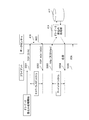
- FIG. 1 is a configuration diagram of a system according to an embodiment.
- the client 201, the management server 301, and the data center 401 are connected via a network and can communicate with each other.
- the client 201 executes various processes and stores data in the data center 401.
- the client 201 is an information processing apparatus such as a personal computer or a mobile terminal.
- the management server 301 collects and manages information of the data center 301.
- the data center 401 is a server that stores data.
- the data center 401 writes and reads data requested from the client 201.
- the data centers 401-1 to 401-6 are assigned data center-a to data center-f as server IDs, respectively.
- the server ID is an identifier that identifies the data center 401.
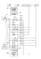
- FIG. 2 is a configuration diagram of the client according to the embodiment.
- the client 201 includes a data center configuration information acquisition unit 211, a dummy data write request processing unit 212, a network (NW) response table processing unit 213, a server response table processing unit 214, a sort table reception processing unit 215, a data division processing unit 216, A data storage destination determination processing unit 217, a data reading / writing processing unit 218, a transmission / reception control unit 219, and a storage unit 220 are provided.
- NW network
- the data center configuration information acquisition unit 211 acquires the data center configuration information 321 from the management server 301 and stores it in the storage unit 220 as the data center configuration information 232.
- the dummy data write request processing unit 212 transmits a connection request and a dummy data write request to the data center 401.
- the NW response table processing unit 213 measures the NW response time and generates the NW response table 233.
- the server response table processing unit 214 measures the server response time and generates the server response table 235.
- the sort table reception processing unit 215 receives the sorted NW response table, the sorted server response table, and the sorted free disk capacity table and stores them in the storage unit 220.
- the data division processing unit 216 divides the write data 231 and generates divided data.
- the data storage destination determination processing unit 217 determines (selects) a storage destination data center for storing the divided data based on at least one of the network response time, the server response time, and the free disk capacity.
- the data storage destination determination processing unit 217 determines, for example, a predetermined number (for example, 10) of data centers as the storage destination data center in order of increasing network response time.
- the data storage destination determination processing unit 217 determines, for example, a predetermined number (for example, 10) of data centers as the storage destination data center in order of increasing server response time.
- the data storage destination determination processing unit 217 does not determine, for example, a data center whose free disk capacity is a predetermined capacity or less as a storage destination data center. That is, the data storage destination determination processing unit 217 determines a data center having a free disk capacity larger than a predetermined capacity as the storage destination data center.
- the data storage destination determination processing unit 217 cyclically selects (assigns) a storage destination data center for each divided data. Cyclic selection means that the storage destination data center is selected from the list of storage destination data centers arranged in order of network response time or server response time in order from the top, and when the end of the list is reached, Returning to the beginning (wraparound), selecting in turn again.
- the data storage destination determination processing unit 217 stores the storage destination data centers ⁇ ⁇ ⁇ ⁇ ⁇ ⁇ ⁇ ⁇ ⁇ ⁇ for each divided data. Select in the order of ⁇ ⁇ .
- the data storage destination determination processing unit 217 creates the divided data management table 239.
- the data read / write processing unit 218 transmits the divided data to the data center 401 and receives the divided data from the data center 401. Further, the data reading / writing processing unit 218 combines the received divided data.
- the transmission / reception control unit 219 includes a data center configuration information acquisition unit 211, a dummy data write request processing unit 212, an NW response table processing unit 213, a server response table processing unit 214, a sort table reception processing unit 215, a data division processing unit 216, data Data is received from the storage destination determination processing unit 217 and the data read / write processing unit 218, and the data is transferred to the management server 301 or the data center 401. Also, the transmission / reception control unit 219 receives data from the management server 301 or the data center 401, and transmits the data to the data center configuration information acquisition unit 211, dummy data write request processing unit 212, NW response table processing unit 213, server response table processing. The data is transferred to the unit 214, sort table reception processing unit 215, data division processing unit 216, data storage destination determination processing unit 217, or data read / write processing unit 218.
- the storage unit 220 is a device that stores data.
- the storage unit 220 is, for example, a magnetic disk device, a semiconductor storage device, or a random access memory (RAM).
- the storage unit 220 includes write data 231, data center configuration information 232, network (NW) response table 233, sorted NW response table 234, server response table 235, sorted server response table 236, sorted free disk capacity table 237, A data division condition table 238 and a divided data management table 239 are stored.
- the write data 231 is data before division written in the data center 401.
- the write data 231 is generated by application software that operates on the client 201, for example.
- the data center configuration information 232 is information on the data center 401 in the system 101.
- FIG. 3 is a diagram illustrating an example of data center configuration information.
- the data center configuration information 232 includes, as items, a server ID, an Internet Protocol (IP) address, and a Uniform Resource Locator (URL).
- IP Internet Protocol
- URL Uniform Resource Locator
- the server ID is an identifier that identifies the data center 401.
- the IP address is the IP address of the data center 401.
- the URL is the URL of the data center 401.
- the network (NW) response table 233 is a table in which the network response time between the client 201 and the data center 401 is described.
- the network response time is the time from when the client 201 transmits a connection request (SYN packet) to the data center 401 until it receives an acknowledgment (ACK packet). Details of the network response time will be described later.
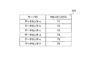
- FIG. 4 is a diagram illustrating an example of the NW response table.
- the NW response table 233 includes a server ID and an NW response time as items.
- the server ID and the NW response time are described in association with each other.
- the server ID is an identifier that identifies the data center 401.
- the NW response time is a network response time between the client 201 and the data center 401.
- the unit of NW response time is milliseconds (ms).
- the sorted NW response table 234 is a table in which records of the NW response table 322 described later are sorted in ascending order of NW response time.
- FIG. 5 is a diagram illustrating an example of a sorted NW response table.
- the sorted NW response table 234 has a server ID and an NW response time as items.
- the server ID and the NW response time are described in association with each other.
- the server ID is an identifier that identifies the data center 401.
- the NW response time is a network response time between the client 201 and the data center 401.
- the unit of NW response time is milliseconds (ms).
- the server response table 235 is a table in which the server response time between the client 201 and the data center 401 is described.
- the server response time is the time from when the client 201 sends a dummy data write request to the data center 401 until it receives a response. Details of the server response time will be described later.
- FIG. 6 is a diagram illustrating an example of a server response table.
- the server response table 235 has a server ID and a server response time as items.
- a server ID and a server response time are described in association with each other.
- the server ID is an identifier that identifies the data center 401.
- the server response time is a server response time between the client 201 and the data center 401.
- the unit of the server response time is milliseconds (ms).
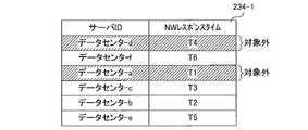
- the sorted server response table 236 is a table in which records in a server response table 323 described later are sorted in ascending order of server response time.
- FIG. 7 is a diagram illustrating an example of a sorted server response table.
- the sorted server response table 236 includes a server ID and a server response time as items.
- the server ID and the server response time are described in association with each other.
- the server ID is an identifier that identifies the data center 401.
- the server response time is a server response time between the client 201 and the data center 401.
- the unit of the server response time is milliseconds (ms).
- the sorted free disk capacity table 237 is a table in which records of a free disk capacity table 324 described later are sorted in descending order of free disk capacity.
- the sorted free disk capacity table 237 is a table in which the free disk capacity of the data center 401 is described.
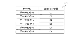
- FIG. 8 is an example of a sorted free disk capacity table.
- the sorted free disk capacity table 237 includes a server ID and a free disk capacity as items.
- the server ID and the free disk capacity are described in association with each other.
- the server ID is an identifier that identifies the data center 401.
- the free disk capacity is the size of the free area of the storage unit provided in the data center 401.
- the unit of the free disk capacity is gigabyte (GB).
- the data division condition table 238 is a table in which a policy when the data division processing unit 216 divides data is described.
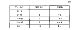
- FIG. 9 is an example of a data division condition table.
- the data division condition table 238 includes data size, division size, and number of divisions as items.
- the data size, the division size, and the number of divisions are described in association with each other.
- the data size indicates the size of the data to be divided.
- the unit of data size is megabyte (MB).
- the division size indicates the size of the divided data.
- the unit of the division size is MB.
- the number of divisions indicates the number of divided data when the data to be divided is divided by the division size.
- the second line of the data division condition table 238 in FIG. 9 divides the data to be divided every 5 MB when the size of the data to be divided is larger than 5 MB and 15 MB or less, thereby dividing the data into 3 or less. Indicates that data will be generated.
- the divided data management table 239 is a table in which information indicating the storage destination of divided data is described.
- FIG. 10 is an example of a divided data management table.
- the divided data management table 239 has, as items, a server ID, an IP address, a URL, and a write file name.
- a server ID, an IP address, a URL, and a write data name are described in association with each other.
- the server ID is an identifier that identifies the data center 401.
- the IP address is the IP address of the data center 401.
- the URL is the URL of the data center 401.
- the write data name is the name (file name) of the divided write data (divided data).
- the format of the write data name is “name of write data 231” ⁇ “division number”.
- the division number is a number assigned to the divided data in order. For example, the write data name “Abc-1” indicates the first data among the data obtained by dividing the write data 231 whose name is “Abc”.
- the second row of the divided data management table 239 indicates that the divided data with the name “Abc-1” is stored in the data center with the server ID “data center-f”. That is, it indicates that the first data among the data obtained by dividing the write data 231 with the name “Abc” is stored in the data center with the server ID “data center-f”.
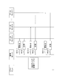
- FIG. 11 is a configuration diagram of the management server according to the embodiment.
- the management server 301 includes a data center configuration information processing unit 311, NW response table processing unit 312, server response table processing unit 313, free disk capacity table processing unit 314, disk capacity inquiry processing unit 315, sort processing unit 316, transmission / reception control A unit 317 and a storage unit 318.
- the data center configuration information processing unit 311 transmits the data center configuration information 321 to the client 201.
- the NW response table processing unit 312 receives the NW response table 233 from the client 201 and stores it in the storage unit 318 as the NW response table 322.
- the server response table processing unit 313 receives the server response table 235 from the client 201 and stores it in the storage unit 318 as the server response table 323.
- the free disk capacity table processing unit 314 creates and updates the free disk capacity table 324.
- the disk capacity inquiry processing unit 315 queries the data center 401 for the free disk capacity and acquires information on the free disk capacity.
- the sort processing unit 316 sorts the records of the NW response table 322, the server response table 323, and the free disk capacity table 324.
- the transmission / reception control unit 317 includes the data center configuration information processing unit 311, the NW response table processing unit 312, the server response table processing unit 313, the free disk capacity table processing unit 314, the disk capacity inquiry processing unit 315, and the sort processing unit 316.
- Data is received, and the data is transferred to the client 201 or the data center 401.
- the transmission / reception control unit 317 receives data from the client 201 or the data center 401 and transmits the data to the data center configuration information processing unit 311, the NW response table processing unit 312, the server response table processing unit 313, and the free disk capacity table processing unit. 314, and transfer to the disk capacity inquiry processing unit 315 or sort processing unit 316.
- the storage unit 318 is a device that stores data.
- the storage unit 318 is, for example, a magnetic disk device, a semiconductor storage device, or a RAM.
- the storage unit 318 stores data center configuration information 321, NW response table 322, server response table 323, and free disk capacity table 324.
- the data center configuration information 321 is information on the data center 401 in the system 101. Since the format of the data center configuration information 321 is the same as that of the data center configuration information 232 described above, description thereof is omitted.
- the NW response table 322 is a table in which the network response time between the client 201 and the data center 401 is described. Since the format of the NW response table 322 is the same as that of the above-described NW response table 233, description thereof is omitted.
- the server response table 323 is a table in which the server response time between the client 201 and the data center 401 is described.
- the server response time is the time from when the client 201 sends a dummy data write request to the data center 401 until it receives a response. Details of the server response time will be described later. Since the format of the server response table 323 is the same as the server response table 235 described above, the description thereof is omitted.
- the free disk capacity table 324 is a table in which the size of the free disk capacity of the data center 401 is described.
- FIG. 12 is an example of a completed free disk capacity table.
- the free disk capacity table 324 includes a server ID and a free disk capacity as items. In the free disk capacity table 324, the server ID and the free disk capacity are described in association with each other.
- the server ID is an identifier that identifies the data center 401.
- the free disk capacity is the size of the free area of the storage unit provided in the data center 401.
- the unit of the free disk capacity is gigabyte (GB).
- FIG. 13 is a configuration diagram of a data center according to the embodiment.
- the data center 401-1 includes a disk capacity check processing unit 411, a data reading processing unit 412, a data writing processing unit 413, a dummy data writing processing unit 414, a transmission / reception control unit 415, a network interface card (NIC) 416, and a storage unit 417. Is provided.
- NIC network interface card
- the disk capacity check processing unit 411 checks the size of the free capacity in the storage unit 417.
- the data read processing unit 412 reads data from the storage unit 417.
- the data write processing unit 413 writes data in the storage unit 417.
- the dummy data write processing unit 414 writes the dummy data 401 into the storage unit 401.
- the dummy data is data having a small size (for example, 100 bytes).
- the contents of the dummy data are arbitrary.
- the transmission / reception control unit 415 receives data from the disk capacity check processing unit 411, the data read processing unit 412, the data write processing unit 413, and the dummy data write processing unit 414, and transfers the data to the NIC 416.
- the transmission / reception control unit 415 receives data from the NIC 416 and transfers the data to the disk capacity check processing unit 411, the data read processing unit 412, the data write processing unit 413, or the dummy data write processing unit 414.
- the NIC 416 is an expansion card that connects to the network and communicates with the client 201 and the management server 301.
- the NIC 416 receives data from the client 201 or the management server 301 and transfers it to the transmission / reception control unit 415. In addition, data is received from the transmission / reception control unit 415 and transferred to the client 201 or the management server 301.
- the NIC 416 transmits an acknowledgment (ACK packet) to the connection request (SYN packet) to the client 201.
- ACK packet acknowledgment
- SYN packet connection request
- the storage unit 417 is a device that stores data.
- the storage unit 417 is, for example, a magnetic disk device, a semiconductor storage device, or a RAM.
- the storage unit 417 stores the divided data 421.
- the divided data 421 is a part of the divided write data 231.
- the configuration of the data centers 401-2 to 401-6 is the same as that of the data center 401-1 and will not be described.
- FIG. 14 is a sequence diagram of measurement processing of network response time and server response time.
- TCP Transmission Control Protocol
- the client 201 starts dummy data write processing. First, the client 201 transmits a connection request (SYN packet) to the data center 401-1 (S 501).
- the NIC 416 transmits an acknowledgment (ACK packet) to the connection request to the client 201 (S502).
- the client 201 receives an acknowledgment (ACK packet).
- the client 201 measures the time from when the client 201 transmits a connection request (SYN packet) until it receives an acknowledgment (ACK packet), and uses that time as the network response time.
- the client 201 transmits a dummy data write request to the data center 401-1 using HyperText Transfer Protocol (HTTP) or Hypertext Transfer Protocol over Secure Socket Layer (HTTPS) (S503).
- HTTP HyperText Transfer Protocol
- HTTPS Hypertext Transfer Protocol over Secure Socket Layer
- the dummy data write processing unit 414 When the dummy data write processing unit 414 receives the dummy data write request, the dummy data write processing unit 414 writes the dummy data into the storage unit 417. When the writing is completed, the dummy data writing processing unit 414 responds to the client 201 with the writing completion (S504).
- the client 201 receives a write completion response.
- the client 201 measures the time from when the client 201 sends a dummy data write request until it receives a write completion response, and uses this time as the server response time.
- the client 201 transmits a FIN packet to the data center 401-1 and ends the communication (S505).
- network response time and server response time measurement processes of the data centers 401-2 to 401-6 are the same as the network response time and server response time measurement processes of the data center 401-1 described above.
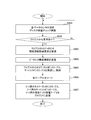
- FIG. 15 is a flowchart of client data storage processing according to the embodiment.
- the client 201 generates write data 231 through processing by application software, and starts data storage processing for storing the write data 231.
- step S 511 the data center configuration information acquisition processing unit 211 transmits a data center configuration information acquisition request to the management server 301, receives the data center configuration information 321 from the management server 301, and stores the data center configuration information 232 as the storage unit 220. To store.
- step S 512 the dummy data write request processing unit 212 executes dummy data write processing for each data center 401 described in the data center configuration information 232, and the NW response time and server response time of each data center 401. Measure.
- the NW response table processing unit 213 creates the NW response table 233. Specifically, the NW response table processing unit 213 describes the server ID and the measured NW response time in the NW response table 233 in association with each other. Then, the NW response table processing unit 213 transmits the NW response table 233 to the management server 301.
- step S514 the server response table processing unit 214 creates the server response table 235. Specifically, the server response table processing unit 214 describes the server ID and the measured server response time in the server response table 235 in association with each other. Then, the server response table processing unit 214 transmits the server response table 235 to the management server 301.
- step S515 the sort table reception processing unit 215 receives the sorted NW response table, the sorted server response table, and the sorted free disk capacity table from the management server 301.
- the sorted NW response table 234, the sorted server The response table 235 and the sorted free disk capacity table 237 are stored in the storage unit 220.
- step S516 the data division processing unit 216 refers to the data division condition table 238, divides the write data 231 according to the conditions described in the data division condition table 238, and generates divided data.
- the data storage destination determination processing unit 217 refers to at least one of the sorted NW response table 234, the sorted server response table 235, and the sorted free disk capacity table 237, and stores the divided data.
- a data center is determined based on a predetermined condition. Predetermined conditions include NW response time priority, server response time priority, and free disk capacity larger than a threshold.
- the data center that stores the divided data is called a storage destination data center. An example of determining the storage destination data center will be described later.
- step S518, the data storage destination determination processing unit 217 creates the divided data management table 239. Specifically, the data storage destination determination processing unit 217 describes the server ID of the storage destination data center and the name of the divided data in the divided data management table 239 in association with each other.
- step S519 the data reading / writing processing unit 217 transmits the divided data to the storage destination data center based on the divided data management table 239, respectively.
- step S5 Details processing from acquisition of the data center configuration information (step S511) to reception of the sorted table (step S515) will be described.
- FIG. 16 is a sequence diagram from the acquisition of the data center configuration information to the acquisition of the sorted table according to the embodiment.
- FIG. 16 corresponds to steps S511 to S515 in FIG.
- the data center configuration information acquisition processing unit 211 transmits a data center configuration information acquisition request to the management server 301 (step S521).
- the data center configuration information processing unit 311 When receiving the data center configuration information acquisition request, the data center configuration information processing unit 311 transmits the data center configuration information 321 to the client 201 (step S522), and the data center configuration information acquisition processing unit 211 receives the data center configuration information 321. Receive.
- the data center configuration information acquisition processing unit 211 stores the received data center configuration information 321 in the storage unit 220 as the data center configuration information 232.
- the dummy data write request processing unit 212 transmits a connection request (SYN packet) to the data center 401-1 (S523-1).
- the NIC 416 transmits an acknowledgment (ACK packet) to the connection request to the client 201 (S524-1).
- the NW response table processing unit 213 measures the time from when the connection request (SYN packet) is transmitted to the data center 401-1 to when the confirmation response (ACK packet) is received, and the time is stored in the data center 401-1.
- the network response time is described in the NW response table 233.
- the dummy data write request processing unit 212 transmits a dummy data write request to the data center 401-1 using HTTP or HTTPS (S 525-1).
- the dummy data write processing unit 414 When the dummy data write processing unit 414 receives the dummy data write request, the dummy data write processing unit 414 writes the dummy data into the storage unit 417. When the writing is completed, the dummy data writing processing unit 414 responds to the client 201 with the writing completion (S526-1).
- the server response table processing unit 214 measures the time from when the client 201 sends a dummy data write request until it receives a write completion response, and uses this time as the server response time of the data center 401-1 It is described in the table 235.
- the NW response time and server response time of the data centers 401-2 to 401-6 are measured, and the measured NW response time and server response time of the data centers 401-2 to 401-6 are measured in the NW response table 233 and Each is described in the server response time table 235 (steps S523-2 to S526-6).
- the NW response table processing unit 213 After creating the NW response table 233 and the server response time table 235, the NW response table processing unit 213 transmits the NW response table 233 to the management server 301, and the server response table processing unit 214 sends the server response table 235 to the management server 301. (Step S527).
- the sort table reception processing unit 215 receives the sorted NW response table, the sorted server response table, and the sorted free disk capacity table from the management server 301, and sorts the NW response table 234 and the sorted server response table. 235 and the sorted free disk capacity table 237 are stored in the storage unit 220 (step S528).
- FIG. 17 is a flowchart of processing of the management server according to the embodiment.
- the disk capacity inquiry unit 315 checks the free disk capacity of each data center 401. Specifically, the disk capacity inquiry unit 315 transmits a free disk capacity check request for inquiring about the free disk capacity to each data center 401. The disk capacity inquiry unit 315 receives a free disk capacity response (size of free disk capacity) from each data center 401.
- the free disk capacity table processing unit 314 describes the received free disk capacity information in the free disk capacity table 324. Acquisition of free disk capacity information is performed periodically (for example, every hour). Details of obtaining information on the free disk capacity will be described later.
- step S602 if there is a data center configuration information acquisition request from the client 201, the control proceeds to step S603, and if there is no data center configuration information acquisition request, the control returns to step S601.
- step S603 the data center configuration information processing unit 311 receives a data center configuration information acquisition request from the client 201.
- step S604 the data center configuration information processing unit 311 transmits the data center configuration information 321 to the client 201.
- step S605 the NW response table processing unit 312 receives the NW response table 233 from the client 201 and stores it in the storage unit 318 as the NW response table 322.
- the server response table processing unit 313 receives the server response table 235 from the client 201 and stores it in the storage unit 318 as the server response table 323.
- step S606 the sort processing unit 316 sorts the NW response table 322 in ascending order of network response time, and generates a sorted NW response table.
- the sort processing unit 316 sorts the server response table 323 in ascending order of server response time, and generates a sorted server response table.
- the sort processing unit 316 sorts the free disk capacity table 324 in descending order of free disk capacity, and generates a sorted free disk capacity table.
- step S607 the NW response table processing unit 312 transmits the sorted NW response table to the client 201.
- the server response table processing unit 313 transmits the sorted server response table to the client 201.
- the free disk capacity table processing unit 314 transmits the sorted free disk capacity table to the client 201.
- FIG. 18 is a sequence diagram of the free disk capacity information acquisition processing according to the embodiment.
- FIG. 18 corresponds to step S601 in FIG.
- the disk capacity inquiry unit 315 transmits a free disk capacity check request for inquiring about the free disk capacity to the data center 401-1 (step S 611-1).
- the disk capacity inquiry unit 315 receives a free disk capacity response (size of free disk capacity) from each data center 401-1 (step S 612-1).
- the free disk capacity table processing unit 314 describes the received information on the free disk capacity of the data center 401-1 in the free disk capacity table 324.
- the disk capacity inquiry unit 315 sequentially transmits free disk capacity check requests from the data center 401-2 to the data center 401-6, and information on the free disk capacity of the data centers 401-2 to 401-6. Is described in the free disk capacity table 324 (steps S611-2 to S612-6).
- FIG. 19 is a flowchart of client response processing in the data center according to the embodiment.
- step S701 the NIC 416 receives a connection request (SYN packet) from the client 201, and transmits an acknowledgment (ACK packet) to the client 201.
- SYN packet connection request
- ACK packet acknowledgment
- step S702 if the data center 401-1 receives the dummy data write request, the control proceeds to step S703, and if the dummy data write request is not received, the control proceeds to step S706.
- step S703 the dummy data write processing unit 414 receives a dummy data write request from the client 201.
- step S704 the dummy data write processing unit 414 writes the dummy data in the storage unit 417. Then, the dummy data write processing unit 414 responds to the client 201 with the write completion.
- step S705 if the data center 401-1 receives a data read request or data write request, control proceeds to step S706. If no data read request or data write request is received, control returns to step S701.
- step S706 if the data read processing unit 412 receives a data read request, the control proceeds to step S707, and if the data read processing unit 412 does not receive a data read request, the control proceeds to step S708.
- step S707 the data read processing unit 412 reads the data requested by the data read request from the storage unit 417, and transmits the read data to the client 201.
- step S708 if the data write processing unit 413 receives a data write request, the control proceeds to step S709, and if the data write processing unit 413 does not receive data write, the control returns to step S701.
- the data write processing unit 413 receives the divided data as data to be written in the storage unit 417.
- step S709 the data write processing unit 413 writes the received divided data in the storage unit 417.
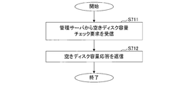
- FIG. 20 is a flowchart of management server response processing of the data center according to the embodiment.
- the disk capacity check processing unit 411 receives the free disk capacity check request from the management server 301, and checks the free disk capacity of the storage unit 417 (step S711).
- the disk capacity check processing unit 411 returns the size of the free disk capacity in the storage unit 417 to the management server 301 as a free disk capacity response (step S712).
- the name of the write data 231 is “Abc”
- the write data 231 is divided, and two divided data are created.
- the names of the two divided data are “Abc-1” and “Abc-2”, respectively.
- the number of data centers used as the storage destination data center is three.
- FIG. 21 is a diagram showing a sorted free disk capacity table.
- FIG. 22 is a diagram showing a sorted NW response table.
- the sorted free disk capacity table 237-1 and the sorted NW response table 234-1 are as shown in FIGS. 21 and 22, respectively.
- the data center configuration information 232 is as shown in FIG.
- the data storage destination determination processing unit 217 refers to the free disk capacity table 237-1, and sets a data center whose free disk capacity is a predetermined value or less (for example, 10G or less) as a target. By excluding data centers whose free disk capacity is equal to or less than a predetermined value from the storage destination data center, it is possible to modify or write existing data stored in the data center.
- a predetermined value or less for example, 10G or less
- the data storage destination determination processing unit 217 refers to the NW response table 234-1, and reflects the information of the data center that is not subject to the NW response table 234-1. That is, the data center-a and data center-d of the NW response table 234-1 are set as excluded.
- the data storage destination determination processing unit 217 creates the divided data management table 239-1 shown in FIG. 23 from the data center configuration information 232 and the sorted NW response table 234-1. However, data is not described in the write data name.
- the server IDs are arranged in order of increasing NW response time.
- the data storage destination determination processing unit 217 stores the three data centers in the descending order of NW response time among the data centers other than the data centers set as excluded from the divided data management table 239-1. Choose as. That is, the data center-f, the data center-c, and the data center-b are selected.
- the divided data is allocated in the order of NW response time.
- the divided data “Abc-1” and “Abc-2” are allocated to the data center-f and the data center-c, respectively.
- the data storage destination determination processing unit 217 describes “Abc-1” and “Abc-2” in the write data names corresponding to the data center-f and data center-c of the divided data management table 239-1, respectively. As a result, a divided data management table 239-1 as shown in FIG. 23 is created. The data storage destination determination processing unit 217 stores the divided data management table 239-1 in the storage unit 220 in association with the data name “Abc”.
- the data read / write processing unit 218 transmits the divided data “Abc-1” and “Abc-2” to the data center 401-6 and the data center 401-3, respectively.
- the name of the write data 231 is “Def”
- the write data 231 is divided, and three divided data are created.
- the names of the three divided data are “Def-1”, “Def-2”, and “Def-3”, respectively.
- the number of data centers used as the storage destination data center is three.
- FIG. 24 is a diagram showing a sorted free disk capacity table.
- FIG. 25 is a diagram illustrating a sorted server response table.
- the sorted free disk capacity table 237-2 and the sorted server response table 236-2 are as shown in FIGS. 24 and 25, respectively.
- the data center configuration information 232 is as shown in FIG.
- the data storage destination determination processing unit 217 refers to the free disk capacity table 237-2 and sets a data center whose free disk capacity is a predetermined value or less (for example, 10G or less) as a target. By excluding data centers whose free disk capacity is equal to or less than a predetermined value from the storage destination data center, it is possible to modify or write existing data stored in the data center.
- a predetermined value or less for example, 10G or less
- the data storage destination determination processing unit 217 refers to the server response table 236-2, and reflects the information of the data center that is excluded from the server response table 236-2. That is, the data center-a and data center-d of the server response table 236-2 are set as excluded.
- the data storage destination determination processing unit 217 creates a divided data management table 239-1 shown in FIG. 26 from the data center configuration information 232 and the sorted server response table 236-2. However, data is not described in the write data name.
- the server IDs are arranged in order of server response time.
- the data storage destination determination processing unit 217 stores the three data centers in the order of the server response time in the data center excluding the data center set as the non-target in the divided data management table 239-2. Choose as. That is, the data center-b, the data center-f, and the data center-e are selected.
- the divided data is allocated in the order of NW response time.
- the divided data “Def-1”, “Def-2”, and “Def-3” are allocated to the data center-b, the data center-f, and the data center-e, respectively.
- the data storage destination determination processing unit 217 assigns “Def-1”, “Def-2”, and “Def-3” to the data center-b, data center-f, and data center-of the divided data management table 239-2. Describe each write data name corresponding to e. Thereby, a divided data management table 239-2 as shown in FIG. 26 is created.
- the data storage destination determination processing unit 217 stores the divided data management table 239-2 in the storage unit 220 in association with the data name “Def”.
- the data read / write processing unit 218 transfers the divided data “Def-1”, “Def-2”, and “Def-3” to the data center 401-2, the data center 401-6, and the data center 401-5. Send each one.
- the data read / write processing unit 218 reads the divided data from the data center 401 and combines the divided data. Thereby, data before division is generated.
- the data read / write processing unit 218 refers to the divided data management table 239-1 associated with the data name “Abc”.
- the divided data “Abc-1” and “Abc-2” are stored in the data center 401-6 and the data center 401-3, respectively. is described.
- the data read / write processing unit 218 reads the divided data “Abc-1” and “Abc-2” from the data center 401-6 and the data center 401-3, respectively, and divides the divided data “Abc-1”. Data “Abc-2” is combined to generate data “Abc” before division.
- the data read / write processing unit 218 refers to the divided data management table 239, identifies the data center 401 that stores the divided data, reads the divided data from the identified data center 401, and obtains the divided data. Combine and generate pre-split data.
- the client can select a data center that does not take time for the storage process.
- the load on a specific data center can be reduced by dividing the data into a plurality of data and storing the data in different data centers.
- FIG. 27 is a configuration diagram of an information processing apparatus (computer).
- the client 201, the management server 301, and the data center 401 according to the embodiment are realized by an information processing apparatus 1 as illustrated in FIG. 27, for example.
- the information processing apparatus 1 includes a CPU 2, a memory 3, an input unit 4, an output unit 5, a storage unit 6, a recording medium drive unit 7, and a network connection unit 8, which are connected to each other by a bus 9.
- the CPU 2 is a central processing unit that controls the entire information processing apparatus 1.
- the CPU 2 includes a data center configuration information acquisition unit 211, a dummy data write request processing unit 212, an NW response table processing unit 213, a server response table processing unit 214, a sort table reception processing unit 215, a data division processing unit 216, and a data storage destination determination.
- the memory 3 is a Read Only Memory (ROM) or Random Access Memory (RAM) that temporarily stores a program or data stored in the storage unit 6 (or the portable recording medium 10) during program execution. It is memory.
- the CPU 2 executes the various processes described above by executing a program using the memory 3.
- the program code itself read from the portable recording medium 10 or the like realizes the functions of the embodiment.
- the input unit 4 is, for example, a keyboard, a mouse, a touch panel, or the like.
- the output unit 5 is, for example, a display, a printer, or the like.
- the storage unit 6 is, for example, a magnetic disk device, an optical disk device, a tape device, or the like.
- the information processing apparatus 1 stores the above-described program and data in the storage unit 6 and reads them into the memory 3 and uses them as necessary.
- the memory 3 or the storage unit 6 corresponds to the storage units 220, 318, and 417.
- the recording medium driving unit 7 drives the portable recording medium 10 and accesses the recorded contents.
- the portable recording medium any computer-readable recording medium such as a memory card, a flexible disk, a compact disk read only memory (CD-ROM), an optical disk, and a magneto-optical disk is used.
- the user stores the above-described program and data in the portable recording medium 10 and reads them into the memory 3 and uses them as necessary.
- the network connection unit 8 is connected to an arbitrary communication network such as a LAN, and performs data conversion accompanying communication.
- the network connection unit 8 corresponds to the NIC 416.
Abstract
Data is segmented into a plurality of segmented data. On the basis of network response time and server response time, a data center storage destination is established from among a plurality of data centers. Storing processing time is minimized by storing the segmented data in the established data center.
Description
本発明は、情報処理装置およびデータ保存処理プログラムに関する。
The present invention relates to an information processing apparatus and a data storage processing program.
現在、ネットワークを介して計算機資源(例えば、サーバ、ストレージ、アプリケーションなど)を利用する形態、いわゆるクラウドコンピューティングが行われている。
Currently, so-called cloud computing is used, in which computer resources (for example, servers, storage, applications, etc.) are used via a network.
クラウドコンピューティングにおいて、ユーザは、パーソナルコンピュータ等のクライアントを用いて各種作業を実行する。
In cloud computing, a user performs various operations using a client such as a personal computer.
ユーザがデータを保存する場合、該データは、サービスを提供しているクラウドサーバに保存される。
When the user saves data, the data is saved on a cloud server that provides the service.
クラウドサーバにデータを保存する場合、クライアントは通常、クラウドサーバの内の決められたデータセンタにデータを保存する。
When storing data in the cloud server, the client normally stores data in a predetermined data center in the cloud server.
しかしながら、当該データセンタに多数のクライアントからのアクセス集中による処理遅延、またはクライアントとデータセンタ間のネットワーク障害や多量のパケットによるネットワーク遅延が発生すると保存処理に時間が掛かってしまう。
However, if a processing delay due to concentration of access from a large number of clients in the data center, or a network failure between the client and the data center or a network delay due to a large number of packets, the storage process takes time.
本発明の課題は、保存処理に要する時間を低減することである。
An object of the present invention is to reduce the time required for the storage process.
実施の形態の情報処理装置は、複数のサーバと通信可能であり、記憶部、分割部、保存先決定部、および送信部を備える。
The information processing apparatus according to the embodiment can communicate with a plurality of servers, and includes a storage unit, a division unit, a storage destination determination unit, and a transmission unit.
前記記憶部は、サーバに対する接続要求の送信から、該接続要求に対する応答の受信までの時間であるネットワークレスポンスタイムが記述されたネットワークレスポンステーブルおよびサーバに対するデータの書込み要求を送信してから、該書き込み完了の応答を受信するまでの時間であるサーバレスポンスタイムが記述されたサーバレスポンステーブルとを含む。
The storage unit transmits a network response table in which a network response time, which is a time from transmission of a connection request to the server to reception of a response to the connection request, and a data write request to the server is transmitted, and then the write A server response table in which a server response time, which is a time until receiving a completion response, is described.
前記分割部は、書込みデータを分割し、分割データを生成する。
前記保存先決定部は、前記ネットワークレスポンスタイムまたは前記サーバレスポンスタイムに基づいて、前記分割データを保存する保存先サーバを決定する。 The dividing unit divides write data and generates divided data.
The storage destination determination unit determines a storage destination server that stores the divided data based on the network response time or the server response time.
前記送信部は、前記分割データを前記保存先サーバに送信する。
The transmission unit transmits the divided data to the storage destination server.
実施の形態の情報処理装置によれば、保存処理に要する時間を低減することできる。
According to the information processing apparatus of the embodiment, the time required for the storage process can be reduced.
以下、図面を参照しながら実施の形態について説明する。
図1は、実施の形態に係るシステムの構成図である。 Hereinafter, embodiments will be described with reference to the drawings.
FIG. 1 is a configuration diagram of a system according to an embodiment.
図1は、実施の形態に係るシステムの構成図である。 Hereinafter, embodiments will be described with reference to the drawings.
FIG. 1 is a configuration diagram of a system according to an embodiment.
システム101は、クライアント201、管理サーバ301、およびデータセンタ401-i(i=1~6)を備える。
The system 101 includes a client 201, a management server 301, and a data center 401-i (i = 1 to 6).
クライアント201、管理サーバ301、およびデータセンタ401は、ネットワークを介して接続されており、互いに通信可能となっている。
The client 201, the management server 301, and the data center 401 are connected via a network and can communicate with each other.
クライアント201は、各種処理を実行し、データをデータセンタ401に保存する。
クライアント201は、例えば、パーソナルコンピュータや携帯端末などの情報処理装置である。 Theclient 201 executes various processes and stores data in the data center 401.
Theclient 201 is an information processing apparatus such as a personal computer or a mobile terminal.
クライアント201は、例えば、パーソナルコンピュータや携帯端末などの情報処理装置である。 The
The
管理サーバ301は、データセンタ301の情報の収集や管理を行う。
データセンタ401は、データを格納するサーバである。データセンタ401は、クライアント201から要求されたデータの書き込みおよび読み出しを行う。 Themanagement server 301 collects and manages information of the data center 301.
The data center 401 is a server that stores data. The data center 401 writes and reads data requested from theclient 201.
データセンタ401は、データを格納するサーバである。データセンタ401は、クライアント201から要求されたデータの書き込みおよび読み出しを行う。 The
The data center 401 is a server that stores data. The data center 401 writes and reads data requested from the
また、データセンタ401-1~401-6には、サーバIDとして、データセンタ-a~データセンタ-fがそれぞれ割り当てられている。サーバIDは、データセンタ401を識別する識別子である。
The data centers 401-1 to 401-6 are assigned data center-a to data center-f as server IDs, respectively. The server ID is an identifier that identifies the data center 401.
図2は、実施の形態に係るクライアントの構成図である。
クライアント201は、データセンタ構成情報取得部211、ダミーデータ書込み要求処理部212、ネットワーク(NW)レスポンステーブル処理部213、サーバレスポンステーブル処理部214、ソートテーブル受信処理部215、データ分割処理部216、データ保存先決定処理部217、データ読込・書込処理部218、送受信制御部219、および記憶部220を備える。 FIG. 2 is a configuration diagram of the client according to the embodiment.
Theclient 201 includes a data center configuration information acquisition unit 211, a dummy data write request processing unit 212, a network (NW) response table processing unit 213, a server response table processing unit 214, a sort table reception processing unit 215, a data division processing unit 216, A data storage destination determination processing unit 217, a data reading / writing processing unit 218, a transmission / reception control unit 219, and a storage unit 220 are provided.
クライアント201は、データセンタ構成情報取得部211、ダミーデータ書込み要求処理部212、ネットワーク(NW)レスポンステーブル処理部213、サーバレスポンステーブル処理部214、ソートテーブル受信処理部215、データ分割処理部216、データ保存先決定処理部217、データ読込・書込処理部218、送受信制御部219、および記憶部220を備える。 FIG. 2 is a configuration diagram of the client according to the embodiment.
The
データセンタ構成情報取得部211は、データセンタ構成情報321を管理サーバ301から取得し、記憶部220にデータセンタ構成情報232として格納する。
The data center configuration information acquisition unit 211 acquires the data center configuration information 321 from the management server 301 and stores it in the storage unit 220 as the data center configuration information 232.
ダミーデータ書込み要求処理部212は、接続要求やダミーデータ書込み要求をデータセンタ401に送信する。
The dummy data write request processing unit 212 transmits a connection request and a dummy data write request to the data center 401.
NWレスポンステーブル処理部213は、NWレスポンスタイムの測定やNWレスポンステーブル233の生成を行う。
The NW response table processing unit 213 measures the NW response time and generates the NW response table 233.
サーバレスポンステーブル処理部214は、サーバレスポンスタイムの測定やサーバレスポンステーブル235の生成を行う。
The server response table processing unit 214 measures the server response time and generates the server response table 235.
ソートテーブル受信処理部215は、ソート済みNWレスポンステーブル、ソート済みサーバレスポンステーブル、およびソート済み空きディスク容量テーブルを受信し、記憶部220に格納する。
The sort table reception processing unit 215 receives the sorted NW response table, the sorted server response table, and the sorted free disk capacity table and stores them in the storage unit 220.
データ分割処理部216は、書込みデータ231を分割し、分割データを生成する。
データ保存先決定処理部217は、ネットワークレスポンスタイム、サーバレスポンスタイム、および空きディスク容量の少なくともいずれか一つに基づいて、分割データを保存する保存先データセンタを決定(選択)する。 The datadivision processing unit 216 divides the write data 231 and generates divided data.
The data storage destinationdetermination processing unit 217 determines (selects) a storage destination data center for storing the divided data based on at least one of the network response time, the server response time, and the free disk capacity.
データ保存先決定処理部217は、ネットワークレスポンスタイム、サーバレスポンスタイム、および空きディスク容量の少なくともいずれか一つに基づいて、分割データを保存する保存先データセンタを決定(選択)する。 The data
The data storage destination
データ保存先決定処理部217は、例えば、ネットワークレスポンスタイムの速い順に所定の台数(例えば、10台)のデータセンタを保存先データセンタとして決定する。
The data storage destination determination processing unit 217 determines, for example, a predetermined number (for example, 10) of data centers as the storage destination data center in order of increasing network response time.
また、データ保存先決定処理部217は、例えば、サーバレスポンスタイムの速い順に所定の台数(例えば、10台)のデータセンタを保存先データセンタとして決定する。
Further, the data storage destination determination processing unit 217 determines, for example, a predetermined number (for example, 10) of data centers as the storage destination data center in order of increasing server response time.
また、データ保存先決定処理部217は、例えば、空きディスク容量が所定の容量以下のデータセンタは、保存先データセンタとして決定しない。すなわち、データ保存先決定処理部217は、空きディスク容量が所定の容量より大きいデータセンタを保存先データセンタとして決定する。
Also, the data storage destination determination processing unit 217 does not determine, for example, a data center whose free disk capacity is a predetermined capacity or less as a storage destination data center. That is, the data storage destination determination processing unit 217 determines a data center having a free disk capacity larger than a predetermined capacity as the storage destination data center.
また、データ保存先決定処理部217は、分割データ毎に、保存先データセンタをサイクリックに選択していく(割り当てていく)。サイクリックに選択とは、ネットワークレスポンスタイムまたはサーバレスポンスタイムの速い順に並んでいる保存先データセンタのリストから保存先データセンタを先頭から順番に選択していき、リストの最後に到達したら、リストの先頭の戻り(ラップアラウンド)、再び順番に選択していくことである。
In addition, the data storage destination determination processing unit 217 cyclically selects (assigns) a storage destination data center for each divided data. Cyclic selection means that the storage destination data center is selected from the list of storage destination data centers arranged in order of network response time or server response time in order from the top, and when the end of the list is reached, Returning to the beginning (wraparound), selecting in turn again.
例えば、ネットワークレスポンスタイムが速い順に保存先データセンタα、β、γがある場合に、データ保存先決定処理部217は、分割データ毎に、保存先データセンタα→β→γ→α→β→γ→・・・のような順番で選択する。
For example, when there are storage destination data centers α, β, and γ in order of network response time, the data storage destination determination processing unit 217 stores the storage destination data centers α → β → γ → α → β → for each divided data. Select in the order of γ →.
データ保存先決定処理部217は、分割データ管理テーブル239を作成する。
データ読込・書込処理部218は、データセンタ401への分割データの送信およびデータセンタ401から分割データを受信する。また、データ読込・書込処理部218は、受信した分割データを結合する。 The data storage destinationdetermination processing unit 217 creates the divided data management table 239.
The data read /write processing unit 218 transmits the divided data to the data center 401 and receives the divided data from the data center 401. Further, the data reading / writing processing unit 218 combines the received divided data.
データ読込・書込処理部218は、データセンタ401への分割データの送信およびデータセンタ401から分割データを受信する。また、データ読込・書込処理部218は、受信した分割データを結合する。 The data storage destination
The data read /
送受信制御部219は、データセンタ構成情報取得部211、ダミーデータ書込み要求処理部212、NWレスポンステーブル処理部213、サーバレスポンステーブル処理部214、ソートテーブル受信処理部215、データ分割処理部216、データ保存先決定処理部217、およびデータ読込・書込処理部218からデータを受信し、データを管理サーバ301またはデータセンタ401に転送する。また、送受信制御部219は、管理サーバ301またはデータセンタ401からデータを受信し、データをデータセンタ構成情報取得部211、ダミーデータ書込み要求処理部212、NWレスポンステーブル処理部213、サーバレスポンステーブル処理部214、ソートテーブル受信処理部215、データ分割処理部216、データ保存先決定処理部217、またはデータ読込・書込処理部218に転送する。
The transmission / reception control unit 219 includes a data center configuration information acquisition unit 211, a dummy data write request processing unit 212, an NW response table processing unit 213, a server response table processing unit 214, a sort table reception processing unit 215, a data division processing unit 216, data Data is received from the storage destination determination processing unit 217 and the data read / write processing unit 218, and the data is transferred to the management server 301 or the data center 401. Also, the transmission / reception control unit 219 receives data from the management server 301 or the data center 401, and transmits the data to the data center configuration information acquisition unit 211, dummy data write request processing unit 212, NW response table processing unit 213, server response table processing. The data is transferred to the unit 214, sort table reception processing unit 215, data division processing unit 216, data storage destination determination processing unit 217, or data read / write processing unit 218.
記憶部220は、データを格納する装置である。記憶部220は、例えば、磁気ディスク装置、半導体記憶装置、またはRandom Access Memory(RAM)等である。
The storage unit 220 is a device that stores data. The storage unit 220 is, for example, a magnetic disk device, a semiconductor storage device, or a random access memory (RAM).
記憶部220は、書き込みデータ231、データセンタ構成情報232、ネットワーク(NW)レスポンステーブル233、ソート済みNWレスポンステーブル234、サーバレスポンステーブル235、ソート済みサーバレスポンステーブル236、ソート済み空きディスク容量テーブル237、データ分割条件テーブル238、および分割データ管理テーブル239を格納する。
The storage unit 220 includes write data 231, data center configuration information 232, network (NW) response table 233, sorted NW response table 234, server response table 235, sorted server response table 236, sorted free disk capacity table 237, A data division condition table 238 and a divided data management table 239 are stored.
書き込みデータ231は、データセンタ401に書き込む分割前のデータである。書き込みデータ231は、例えば、クライアント201で動作するアプリケーションソフトウェアにより生成される。
The write data 231 is data before division written in the data center 401. The write data 231 is generated by application software that operates on the client 201, for example.
データセンタ構成情報232は、システム101内にあるデータセンタ401の情報である。
The data center configuration information 232 is information on the data center 401 in the system 101.
図3は、データセンタ構成情報の例を示す図である。
データセンタ構成情報232は、項目として、サーバID、Internet Protocol(IP)アドレス、Uniform Resource Locator(URL)を有する。データセンタ構成情報232には、サーバID、IPアドレス、およびURLが対応付けられて記述されている。 FIG. 3 is a diagram illustrating an example of data center configuration information.
The datacenter configuration information 232 includes, as items, a server ID, an Internet Protocol (IP) address, and a Uniform Resource Locator (URL). In the data center configuration information 232, a server ID, an IP address, and a URL are described in association with each other.
データセンタ構成情報232は、項目として、サーバID、Internet Protocol(IP)アドレス、Uniform Resource Locator(URL)を有する。データセンタ構成情報232には、サーバID、IPアドレス、およびURLが対応付けられて記述されている。 FIG. 3 is a diagram illustrating an example of data center configuration information.
The data
サーバIDは、データセンタ401を識別する識別子である。
IPアドレスは、データセンタ401のIPアドレスである。
URLは、データセンタ401のURLである。 The server ID is an identifier that identifies the data center 401.
The IP address is the IP address of the data center 401.
The URL is the URL of the data center 401.
IPアドレスは、データセンタ401のIPアドレスである。
URLは、データセンタ401のURLである。 The server ID is an identifier that identifies the data center 401.
The IP address is the IP address of the data center 401.
The URL is the URL of the data center 401.
ネットワーク(NW)レスポンステーブル233は、クライアント201とデータセンタ401との間のネットワークレスポンスタイムが記述されたテーブルである。ネットワークレスポンスタイムは、クライアント201が接続要求(SYNパケット)をデータセンタ401に送信してから確認応答(ACKパケット)を受信するまでの時間である。尚、ネットワークレスポンスタイムの詳細については後述する。
The network (NW) response table 233 is a table in which the network response time between the client 201 and the data center 401 is described. The network response time is the time from when the client 201 transmits a connection request (SYN packet) to the data center 401 until it receives an acknowledgment (ACK packet). Details of the network response time will be described later.
図4は、NWレスポンステーブルの例を示す図である。
NWレスポンステーブル233は、項目として、サーバIDおよびNWレスポンスタイムを有する。NWレスポンステーブル233には、サーバIDおよびNWレスポンスタイムが対応付けられて記述されている。 FIG. 4 is a diagram illustrating an example of the NW response table.
The NW response table 233 includes a server ID and an NW response time as items. In the NW response table 233, the server ID and the NW response time are described in association with each other.
サーバIDは、データセンタ401を識別する識別子である。
NWレスポンスタイムは、クライアント201とデータセンタ401間のネットワークレスポンスタイムである。NWレスポンスタイムの単位は、ミリ秒(ms)である。 The server ID is an identifier that identifies the data center 401.
The NW response time is a network response time between theclient 201 and the data center 401. The unit of NW response time is milliseconds (ms).
NWレスポンスタイムは、クライアント201とデータセンタ401間のネットワークレスポンスタイムである。NWレスポンスタイムの単位は、ミリ秒(ms)である。 The server ID is an identifier that identifies the data center 401.
The NW response time is a network response time between the
ソート済みNWレスポンステーブル234は、後述のNWレスポンステーブル322のレコードをNWレスポンスタイムの小さい順にソートしたテーブルである。
The sorted NW response table 234 is a table in which records of the NW response table 322 described later are sorted in ascending order of NW response time.
図5は、ソート済みNWレスポンステーブルの例を示す図である。
ソート済みNWレスポンステーブル234は、項目として、サーバIDおよびNWレスポンスタイムを有する。ソート済みNWレスポンステーブル234には、サーバIDおよびNWレスポンスタイムが対応付けられて記述されている。 FIG. 5 is a diagram illustrating an example of a sorted NW response table.
The sorted NW response table 234 has a server ID and an NW response time as items. In the sorted NW response table 234, the server ID and the NW response time are described in association with each other.
サーバIDは、データセンタ401を識別する識別子である。
NWレスポンスタイムは、クライアント201とデータセンタ401間のネットワークレスポンスタイムである。NWレスポンスタイムの単位は、ミリ秒(ms)である。 The server ID is an identifier that identifies the data center 401.
The NW response time is a network response time between theclient 201 and the data center 401. The unit of NW response time is milliseconds (ms).
NWレスポンスタイムは、クライアント201とデータセンタ401間のネットワークレスポンスタイムである。NWレスポンスタイムの単位は、ミリ秒(ms)である。 The server ID is an identifier that identifies the data center 401.
The NW response time is a network response time between the
サーバレスポンステーブル235は、クライアント201とデータセンタ401との間のサーバレスポンスタイムが記述されたテーブルである。サーバレスポンスタイムは、クライアント201がダミーデータ書き込み要求をデータセンタ401に送信してから応答を受信するまでの時間である。尚、サーバレスポンスタイムの詳細については後述する。
The server response table 235 is a table in which the server response time between the client 201 and the data center 401 is described. The server response time is the time from when the client 201 sends a dummy data write request to the data center 401 until it receives a response. Details of the server response time will be described later.
図6は、サーバレスポンステーブルの例を示す図である。
サーバレスポンステーブル235は、項目として、サーバIDおよびサーバレスポンスタイムを有する。サーバレスポンステーブル235には、サーバIDおよびサーバレスポンスタイムが対応付けられて記述されている。 FIG. 6 is a diagram illustrating an example of a server response table.
The server response table 235 has a server ID and a server response time as items. In the server response table 235, a server ID and a server response time are described in association with each other.
サーバIDは、データセンタ401を識別する識別子である。
サーバレスポンスタイムは、クライアント201とデータセンタ401間のサーバレスポンスタイムである。サーバレスポンスタイムの単位は、ミリ秒(ms)である。
ソート済みサーバレスポンステーブル236は、後述のサーバレスポンステーブル323のレコードをサーバレスポンスタイムの小さい順にソートしたテーブルである。 The server ID is an identifier that identifies the data center 401.
The server response time is a server response time between theclient 201 and the data center 401. The unit of the server response time is milliseconds (ms).
The sorted server response table 236 is a table in which records in a server response table 323 described later are sorted in ascending order of server response time.
サーバレスポンスタイムは、クライアント201とデータセンタ401間のサーバレスポンスタイムである。サーバレスポンスタイムの単位は、ミリ秒(ms)である。
ソート済みサーバレスポンステーブル236は、後述のサーバレスポンステーブル323のレコードをサーバレスポンスタイムの小さい順にソートしたテーブルである。 The server ID is an identifier that identifies the data center 401.
The server response time is a server response time between the
The sorted server response table 236 is a table in which records in a server response table 323 described later are sorted in ascending order of server response time.
図7は、ソート済みサーバレスポンステーブルの例を示す図である。
ソート済みサーバレスポンステーブル236は、項目として、サーバIDおよびサーバレスポンスタイムを有する。ソート済みサーバレスポンステーブル236には、サーバIDおよびサーバレスポンスタイムが対応付けられて記述されている。 FIG. 7 is a diagram illustrating an example of a sorted server response table.
The sorted server response table 236 includes a server ID and a server response time as items. In the sorted server response table 236, the server ID and the server response time are described in association with each other.
サーバIDは、データセンタ401を識別する識別子である。
サーバレスポンスタイムは、クライアント201とデータセンタ401間のサーバレスポンスタイムである。サーバレスポンスタイムの単位は、ミリ秒(ms)である。 The server ID is an identifier that identifies the data center 401.
The server response time is a server response time between theclient 201 and the data center 401. The unit of the server response time is milliseconds (ms).
サーバレスポンスタイムは、クライアント201とデータセンタ401間のサーバレスポンスタイムである。サーバレスポンスタイムの単位は、ミリ秒(ms)である。 The server ID is an identifier that identifies the data center 401.
The server response time is a server response time between the
ソート済み空きディスク容量テーブル237は、後述する空きディスク容量テーブル324のレコードを空きディスク容量の大きい順にソートしたテーブルである。ソート済み空きディスク容量テーブル237は、データセンタ401の空きディスク容量が記述されたテーブルである。
The sorted free disk capacity table 237 is a table in which records of a free disk capacity table 324 described later are sorted in descending order of free disk capacity. The sorted free disk capacity table 237 is a table in which the free disk capacity of the data center 401 is described.
図8は、ソート済み空きディスク容量テーブルの例である。
ソート済み空きディスク容量テーブル237は、項目として、サーバIDおよび空きディスク容量を有する。ソート済み空きディスク容量テーブル237には、サーバIDおよび空きディスク容量が対応付けられて記述されている。 FIG. 8 is an example of a sorted free disk capacity table.
The sorted free disk capacity table 237 includes a server ID and a free disk capacity as items. In the sorted free disk capacity table 237, the server ID and the free disk capacity are described in association with each other.
サーバIDは、データセンタ401を識別する識別子である。
空きディスク容量は、データセンタ401が備える記憶部の空き領域のサイズである。空きディスク容量の単位は、ギガバイト(GB)である。 The server ID is an identifier that identifies the data center 401.
The free disk capacity is the size of the free area of the storage unit provided in the data center 401. The unit of the free disk capacity is gigabyte (GB).
空きディスク容量は、データセンタ401が備える記憶部の空き領域のサイズである。空きディスク容量の単位は、ギガバイト(GB)である。 The server ID is an identifier that identifies the data center 401.
The free disk capacity is the size of the free area of the storage unit provided in the data center 401. The unit of the free disk capacity is gigabyte (GB).
データ分割条件テーブル238は、データ分割処理部216がデータを分割するときの方針が記述されたテーブルである。
The data division condition table 238 is a table in which a policy when the data division processing unit 216 divides data is described.
図9は、データ分割条件テーブルの例である。
データ分割条件テーブル238は、項目として、データサイズ、分割サイズ、および分割数を有する。データ分割条件テーブル238には、データサイズ、分割サイズ、および分割数が対応付けられて記述されている。 FIG. 9 is an example of a data division condition table.
The data division condition table 238 includes data size, division size, and number of divisions as items. In the data division condition table 238, the data size, the division size, and the number of divisions are described in association with each other.
データサイズは、分割対象のデータのサイズを示す。データサイズの単位はメガバイト(MB)である。
The data size indicates the size of the data to be divided. The unit of data size is megabyte (MB).
分割サイズは、分割データのサイズを示す。分割サイズの単位は、MBである。
分割数は、分割対象のデータを分割サイズで分割したときの分割データの数を示す。 The division size indicates the size of the divided data. The unit of the division size is MB.
The number of divisions indicates the number of divided data when the data to be divided is divided by the division size.
分割数は、分割対象のデータを分割サイズで分割したときの分割データの数を示す。 The division size indicates the size of the divided data. The unit of the division size is MB.
The number of divisions indicates the number of divided data when the data to be divided is divided by the division size.
例えば、図9のデータ分割条件テーブル238の2行目は、分割対象のデータのサイズが5MBより大きく15MB以下の場合に、5MBごとに分割対象のデータを分割し、それにより3個以下の分割データが生成されることを示す。
For example, the second line of the data division condition table 238 in FIG. 9 divides the data to be divided every 5 MB when the size of the data to be divided is larger than 5 MB and 15 MB or less, thereby dividing the data into 3 or less. Indicates that data will be generated.
分割データ管理テーブル239は、分割データの保存先を示す情報が記述されたテーブルである。
The divided data management table 239 is a table in which information indicating the storage destination of divided data is described.
図10は、分割データ管理テーブルの例である。
分割データ管理テーブル239は、項目として、サーバID、IPアドレス、URL、および書き込みファイル名を有する。分割データ管理テーブル239には、サーバID、IPアドレス、URL、および書き込みデータ名が対応付けられて記述されている。 FIG. 10 is an example of a divided data management table.
The divided data management table 239 has, as items, a server ID, an IP address, a URL, and a write file name. In the divided data management table 239, a server ID, an IP address, a URL, and a write data name are described in association with each other.
サーバIDは、データセンタ401を識別する識別子である。
IPアドレスは、データセンタ401のIPアドレスである。 The server ID is an identifier that identifies the data center 401.
The IP address is the IP address of the data center 401.
IPアドレスは、データセンタ401のIPアドレスである。 The server ID is an identifier that identifies the data center 401.
The IP address is the IP address of the data center 401.
URLは、データセンタ401のURLである。
書き込みデータ名は、分割された書込みデータ(分割データ)の名称(ファイル名)である。書き込みデータ名の形式は、“書き込みデータ231の名称”-“分割番号”である。分割番号は、分割データに順番に付される番号である。例えば、書き込みデータ名“Abc-1”は、名称が”Abc”である書き込みデータ231を分割したデータの内の1番目のデータを示す。 The URL is the URL of the data center 401.
The write data name is the name (file name) of the divided write data (divided data). The format of the write data name is “name ofwrite data 231” − “division number”. The division number is a number assigned to the divided data in order. For example, the write data name “Abc-1” indicates the first data among the data obtained by dividing the write data 231 whose name is “Abc”.
書き込みデータ名は、分割された書込みデータ(分割データ)の名称(ファイル名)である。書き込みデータ名の形式は、“書き込みデータ231の名称”-“分割番号”である。分割番号は、分割データに順番に付される番号である。例えば、書き込みデータ名“Abc-1”は、名称が”Abc”である書き込みデータ231を分割したデータの内の1番目のデータを示す。 The URL is the URL of the data center 401.
The write data name is the name (file name) of the divided write data (divided data). The format of the write data name is “name of
例えば、分割データ管理テーブル239の2行目は、サーバIDが“データセンタ-f”であるデータセンタに、名称が”Abc-1”である分割データが格納されていることを示す。すなわち、サーバIDが“データセンタ-f”であるデータセンタに、名称が”Abc”である書き込みデータ231を分割したデータの内の1番目のデータが格納されていることを示す。
For example, the second row of the divided data management table 239 indicates that the divided data with the name “Abc-1” is stored in the data center with the server ID “data center-f”. That is, it indicates that the first data among the data obtained by dividing the write data 231 with the name “Abc” is stored in the data center with the server ID “data center-f”.
図11は、実施の形態に係る管理サーバの構成図である。
管理サーバ301は、データセンタ構成情報処理部311、NWレスポンステーブル処理部312、サーバレスポンステーブル処理部313、空きディスク容量テーブル処理部314、ディスク容量問合わせ処理部315、ソート処理部316、送受信制御部317、および記憶部318を備える。 FIG. 11 is a configuration diagram of the management server according to the embodiment.
Themanagement server 301 includes a data center configuration information processing unit 311, NW response table processing unit 312, server response table processing unit 313, free disk capacity table processing unit 314, disk capacity inquiry processing unit 315, sort processing unit 316, transmission / reception control A unit 317 and a storage unit 318.
管理サーバ301は、データセンタ構成情報処理部311、NWレスポンステーブル処理部312、サーバレスポンステーブル処理部313、空きディスク容量テーブル処理部314、ディスク容量問合わせ処理部315、ソート処理部316、送受信制御部317、および記憶部318を備える。 FIG. 11 is a configuration diagram of the management server according to the embodiment.
The
データセンタ構成情報処理部311は、データセンタ構成情報321をクライアント201に送信する。
The data center configuration information processing unit 311 transmits the data center configuration information 321 to the client 201.
NWレスポンステーブル処理部312は、クライアント201からNWレスポンステーブル233を受信し、NWレスポンステーブル322として記憶部318に格納する。
The NW response table processing unit 312 receives the NW response table 233 from the client 201 and stores it in the storage unit 318 as the NW response table 322.
サーバレスポンステーブル処理部313は、クライアント201からサーバレスポンステーブル235を受信し、サーバレスポンステーブル323として記憶部318に格納する。
The server response table processing unit 313 receives the server response table 235 from the client 201 and stores it in the storage unit 318 as the server response table 323.
空きディスク容量テーブル処理部314は、空きディスク容量テーブル324の作成や更新を行う。
The free disk capacity table processing unit 314 creates and updates the free disk capacity table 324.
ディスク容量問合わせ処理部315は、データセンタ401に空きディスク容量を問合わせ、空きディスク容量の情報を取得する。
The disk capacity inquiry processing unit 315 queries the data center 401 for the free disk capacity and acquires information on the free disk capacity.
ソート処理部316は、NWレスポンステーブル322、サーバレスポンステーブル323、および空きディスク容量テーブル324のレコードをソートする。
The sort processing unit 316 sorts the records of the NW response table 322, the server response table 323, and the free disk capacity table 324.
送受信制御部317は、データセンタ構成情報処理部311、NWレスポンステーブル処理部312、サーバレスポンステーブル処理部313、空きディスク容量テーブル処理部314、ディスク容量問合わせ処理部315、およびソート処理部316からデータを受信し、データをクライアント201またはデータセンタ401に転送する。また、送受信制御部317は、クライアント201またはデータセンタ401からデータを受信し、データをデータセンタ構成情報処理部311、NWレスポンステーブル処理部312、サーバレスポンステーブル処理部313、空きディスク容量テーブル処理部314、ディスク容量問合わせ処理部315、またはソート処理部316に転送する。
The transmission / reception control unit 317 includes the data center configuration information processing unit 311, the NW response table processing unit 312, the server response table processing unit 313, the free disk capacity table processing unit 314, the disk capacity inquiry processing unit 315, and the sort processing unit 316. Data is received, and the data is transferred to the client 201 or the data center 401. Also, the transmission / reception control unit 317 receives data from the client 201 or the data center 401 and transmits the data to the data center configuration information processing unit 311, the NW response table processing unit 312, the server response table processing unit 313, and the free disk capacity table processing unit. 314, and transfer to the disk capacity inquiry processing unit 315 or sort processing unit 316.
記憶部318は、データを格納する装置である。記憶部318は、例えば、磁気ディスク装置、半導体記憶装置、またはRAM等である。
The storage unit 318 is a device that stores data. The storage unit 318 is, for example, a magnetic disk device, a semiconductor storage device, or a RAM.
記憶部318は、データセンタ構成情報321、NWレスポンステーブル322、サーバレスポンステーブル323、および空きディスク容量テーブル324を格納する。
The storage unit 318 stores data center configuration information 321, NW response table 322, server response table 323, and free disk capacity table 324.
データセンタ構成情報321は、システム101内にあるデータセンタ401の情報である。データセンタ構成情報321の形式は、上述のデータセンタ構成情報232と同様であるため、説明は省略する。
The data center configuration information 321 is information on the data center 401 in the system 101. Since the format of the data center configuration information 321 is the same as that of the data center configuration information 232 described above, description thereof is omitted.
NWレスポンステーブル322は、クライアント201とデータセンタ401との間のネットワークレスポンスタイムが記述されたテーブルである。NWレスポンステーブル322の形式は、上述のNWレスポンステーブル233と同様であるため、説明は省略する。
The NW response table 322 is a table in which the network response time between the client 201 and the data center 401 is described. Since the format of the NW response table 322 is the same as that of the above-described NW response table 233, description thereof is omitted.
サーバレスポンステーブル323は、クライアント201とデータセンタ401との間のサーバレスポンスタイムが記述されたテーブルである。サーバレスポンスタイムは、クライアント201がダミーデータ書き込み要求をデータセンタ401に送信してから応答を受信するまでの時間である。尚、サーバレスポンスタイムの詳細については後述する。サーバレスポンステーブル323の形式は、上述のサーバレスポンステーブル235と同様であるため、説明は省略する。
The server response table 323 is a table in which the server response time between the client 201 and the data center 401 is described. The server response time is the time from when the client 201 sends a dummy data write request to the data center 401 until it receives a response. Details of the server response time will be described later. Since the format of the server response table 323 is the same as the server response table 235 described above, the description thereof is omitted.
空きディスク容量テーブル324は、データセンタ401の空きディスク容量のサイズが記述されたテーブルである。
The free disk capacity table 324 is a table in which the size of the free disk capacity of the data center 401 is described.
図12は、済み空きディスク容量テーブルの例である。
空きディスク容量テーブル324は、項目として、サーバIDおよび空きディスク容量を有する。空きディスク容量テーブル324には、サーバIDおよび空きディスク容量が対応付けられて記述されている。 FIG. 12 is an example of a completed free disk capacity table.
The free disk capacity table 324 includes a server ID and a free disk capacity as items. In the free disk capacity table 324, the server ID and the free disk capacity are described in association with each other.
サーバIDは、データセンタ401を識別する識別子である。
空きディスク容量は、データセンタ401が備える記憶部の空き領域のサイズである。空きディスク容量の単位は、ギガバイト(GB)である。 The server ID is an identifier that identifies the data center 401.
The free disk capacity is the size of the free area of the storage unit provided in the data center 401. The unit of the free disk capacity is gigabyte (GB).
空きディスク容量は、データセンタ401が備える記憶部の空き領域のサイズである。空きディスク容量の単位は、ギガバイト(GB)である。 The server ID is an identifier that identifies the data center 401.
The free disk capacity is the size of the free area of the storage unit provided in the data center 401. The unit of the free disk capacity is gigabyte (GB).
図13は、実施の形態に係るデータセンタの構成図である。
データセンタ401-1は、ディスク容量チェック処理部411、データ読込み処理部412、データ書込み処理部413、ダミーデータ書込み処理部414、送受信制御部415、Network Interface Card(NIC)416、および記憶部417を備える。 FIG. 13 is a configuration diagram of a data center according to the embodiment.
The data center 401-1 includes a disk capacitycheck processing unit 411, a data reading processing unit 412, a data writing processing unit 413, a dummy data writing processing unit 414, a transmission / reception control unit 415, a network interface card (NIC) 416, and a storage unit 417. Is provided.
データセンタ401-1は、ディスク容量チェック処理部411、データ読込み処理部412、データ書込み処理部413、ダミーデータ書込み処理部414、送受信制御部415、Network Interface Card(NIC)416、および記憶部417を備える。 FIG. 13 is a configuration diagram of a data center according to the embodiment.
The data center 401-1 includes a disk capacity
ディスク容量チェック処理部411は、記憶部417の空き容量のサイズをチェックする。
The disk capacity check processing unit 411 checks the size of the free capacity in the storage unit 417.
データ読込み処理部412は、記憶部417からデータを読み出す。
データ書込み処理部413は、記憶部417にデータを書き込む。 The data readprocessing unit 412 reads data from the storage unit 417.
The data writeprocessing unit 413 writes data in the storage unit 417.
データ書込み処理部413は、記憶部417にデータを書き込む。 The data read
The data write
ダミーデータ書込み処理部414は、記憶部401にダミーデータ401を書き込む。尚、ダミーデータは、小さいサイズ(例えば、100バイト)のデータである。また、ダミーデータの内容は任意である。
The dummy data write processing unit 414 writes the dummy data 401 into the storage unit 401. The dummy data is data having a small size (for example, 100 bytes). The contents of the dummy data are arbitrary.
送受信制御部415は、ディスク容量チェック処理部411、データ読込み処理部412、データ書込み処理部413、およびダミーデータ書込み処理部414からデータを受信し、データをNIC416に転送する。また、送受信制御部415は、NIC416からデータを受信し、データをディスク容量チェック処理部411、データ読込み処理部412、データ書込み処理部413、またはダミーデータ書込み処理部414に転送する。
The transmission / reception control unit 415 receives data from the disk capacity check processing unit 411, the data read processing unit 412, the data write processing unit 413, and the dummy data write processing unit 414, and transfers the data to the NIC 416. The transmission / reception control unit 415 receives data from the NIC 416 and transfers the data to the disk capacity check processing unit 411, the data read processing unit 412, the data write processing unit 413, or the dummy data write processing unit 414.
NIC416は、ネットワークと接続し、クライアント201および管理サーバ301と通信を行う拡張カードである。NIC416は、クライアント201または管理サーバ301からデータを受信し、送受信制御部415に転送する。また、送受信制御部415からデータを受信し、クライアント201または管理サーバ301に転送する。NIC416は、接続要求(SYNパケット)に対する確認応答(ACKパケット)をクライアント201に送信する。
The NIC 416 is an expansion card that connects to the network and communicates with the client 201 and the management server 301. The NIC 416 receives data from the client 201 or the management server 301 and transfers it to the transmission / reception control unit 415. In addition, data is received from the transmission / reception control unit 415 and transferred to the client 201 or the management server 301. The NIC 416 transmits an acknowledgment (ACK packet) to the connection request (SYN packet) to the client 201.
記憶部417は、データを格納する装置である。記憶部417は、例えば、磁気ディスク装置、半導体記憶装置、またはRAM等である。
The storage unit 417 is a device that stores data. The storage unit 417 is, for example, a magnetic disk device, a semiconductor storage device, or a RAM.
記憶部417は、分割データ421を格納する。分割データ421は、分割された書き込みデータ231の一部である。
The storage unit 417 stores the divided data 421. The divided data 421 is a part of the divided write data 231.
尚、データセンタ401-2~401-6の構成は、データセンタ401-1と同様であるので、説明は省略する。
The configuration of the data centers 401-2 to 401-6 is the same as that of the data center 401-1 and will not be described.
次にネットワークレスポンスタイムとサーバレスポンスタイムの定義および測定処理について述べる。
Next, the definition of network response time and server response time and the measurement process will be described.
図14は、ネットワークレスポンスタイムおよびサーバレスポンスタイムの測定処理のシーケンス図である。
FIG. 14 is a sequence diagram of measurement processing of network response time and server response time.
ここでは、データセンタ401-1のネットワークレスポンスタイムおよびサーバレスポンスタイムの測定について説明する。
Here, measurement of the network response time and server response time of the data center 401-1 will be described.
尚、クライアント201とデータセンタ401-1は、Transmission Control Protocol(TCP)を用いて通信する。
Note that the client 201 and the data center 401-1 communicate with each other using Transmission Control Protocol (TCP).
クライアント201は、ダミーデータ書込み処理を開始する。
先ず、クライアントは201、接続要求(SYNパケット)をデータセンタ401-1に送信する(S501)。 Theclient 201 starts dummy data write processing.
First, theclient 201 transmits a connection request (SYN packet) to the data center 401-1 (S 501).
先ず、クライアントは201、接続要求(SYNパケット)をデータセンタ401-1に送信する(S501)。 The
First, the
NIC416は、接続要求に対する確認応答(ACKパケット)をクライアント201に送信する(S502)。
The NIC 416 transmits an acknowledgment (ACK packet) to the connection request to the client 201 (S502).
そして、クライアント201は、確認応答(ACKパケット)を受信する。
クライアント201は、クライアント201が接続要求(SYNパケット)を送信してから、確認応答(ACKパケット)を受信するまでの時間を測定し、該時間をネットワークレスポンスタイムとする。 Then, theclient 201 receives an acknowledgment (ACK packet).
Theclient 201 measures the time from when the client 201 transmits a connection request (SYN packet) until it receives an acknowledgment (ACK packet), and uses that time as the network response time.
クライアント201は、クライアント201が接続要求(SYNパケット)を送信してから、確認応答(ACKパケット)を受信するまでの時間を測定し、該時間をネットワークレスポンスタイムとする。 Then, the
The
次に、クライアント201は、HyperText Transfer Protocol(HTTP)またはHypertext Transfer Protocol over Secure Socket Layer(HTTPS)を用いて、ダミーデータ書込み要求をデータセンタ401-1に送信する(S503)。
Next, the client 201 transmits a dummy data write request to the data center 401-1 using HyperText Transfer Protocol (HTTP) or Hypertext Transfer Protocol over Secure Socket Layer (HTTPS) (S503).
ダミーデータ書込み処理部414は、ダミーデータ書込み要求を受信すると、ダミーデータを記憶部417に書込む。ダミーデータ書込み処理部414は、書込みが完了したら、書込み完了をクライアント201に応答する(S504)。
When the dummy data write processing unit 414 receives the dummy data write request, the dummy data write processing unit 414 writes the dummy data into the storage unit 417. When the writing is completed, the dummy data writing processing unit 414 responds to the client 201 with the writing completion (S504).
そして、クライアント201は、書込み完了の応答を受信する。
クライアント201は、クライアント201がダミーデータ書込み要求を送信してから、書込み完了の応答を受信するまでの時間を測定し、該時間をサーバレスポンスタイムとする。 Then, theclient 201 receives a write completion response.
Theclient 201 measures the time from when the client 201 sends a dummy data write request until it receives a write completion response, and uses this time as the server response time.
クライアント201は、クライアント201がダミーデータ書込み要求を送信してから、書込み完了の応答を受信するまでの時間を測定し、該時間をサーバレスポンスタイムとする。 Then, the
The
クライアント201は、FINパケットをデータセンタ401-1に送信し、通信を終了する(S505)。
The client 201 transmits a FIN packet to the data center 401-1 and ends the communication (S505).
尚、データセンタ401-2~401-6のネットワークレスポンスタイムおよびサーバレスポンスタイムの測定処理についても、上述のデータセンタ401-1のネットワークレスポンスタイムおよびサーバレスポンスタイムの測定処理と同様である。
Note that the network response time and server response time measurement processes of the data centers 401-2 to 401-6 are the same as the network response time and server response time measurement processes of the data center 401-1 described above.
図15は、実施の形態に係るクライアントのデータ保存処理のフローチャートである。
先ず、クライアント201は、アプリケーションソフトウェアによる処理で書き込みデータ231を生成し、書き込みデータ231を保存するデータ保存処理を開始する。 FIG. 15 is a flowchart of client data storage processing according to the embodiment.
First, theclient 201 generates write data 231 through processing by application software, and starts data storage processing for storing the write data 231.
先ず、クライアント201は、アプリケーションソフトウェアによる処理で書き込みデータ231を生成し、書き込みデータ231を保存するデータ保存処理を開始する。 FIG. 15 is a flowchart of client data storage processing according to the embodiment.
First, the
ステップS511において、データセンタ構成情報取得処理部211は、管理サーバ301にデータセンタ構成情報取得要求を送信し、管理サーバ301からデータセンタ構成情報321を受信し、データセンタ構成情報232として記憶部220に格納する。
In step S 511, the data center configuration information acquisition processing unit 211 transmits a data center configuration information acquisition request to the management server 301, receives the data center configuration information 321 from the management server 301, and stores the data center configuration information 232 as the storage unit 220. To store.
ステップS512において、ダミーデータ書込み要求処理部212は、データセンタ構成情報232に記述されている各データセンタ401に対してダミーデータ書込み処理を実行し、各データセンタ401のNWレスポンスタイムおよびサーバレスポンスタイムを測定する。
In step S 512, the dummy data write request processing unit 212 executes dummy data write processing for each data center 401 described in the data center configuration information 232, and the NW response time and server response time of each data center 401. Measure.
ステップS513において、NWレスポンステーブル処理部213は、NWレスポンステーブル233を作成する。詳細には、NWレスポンステーブル処理部213は、サーバIDと測定したNWレスポンスタイムとを対応付けてNWレスポンステーブル233に記述する。そして、NWレスポンステーブル処理部213は、NWレスポンステーブル233を管理サーバ301に送信する。
In step S513, the NW response table processing unit 213 creates the NW response table 233. Specifically, the NW response table processing unit 213 describes the server ID and the measured NW response time in the NW response table 233 in association with each other. Then, the NW response table processing unit 213 transmits the NW response table 233 to the management server 301.
ステップS514において、サーバレスポンステーブル処理部214は、サーバレスポンステーブル235を作成する。詳細には、サーバレスポンステーブル処理部214は、サーバIDと測定したサーバレスポンスタイムとを対応付けてサーバレスポンステーブル235に記述する。そして、サーバレスポンステーブル処理部214は、サーバレスポンステーブル235を管理サーバ301に送信する。
In step S514, the server response table processing unit 214 creates the server response table 235. Specifically, the server response table processing unit 214 describes the server ID and the measured server response time in the server response table 235 in association with each other. Then, the server response table processing unit 214 transmits the server response table 235 to the management server 301.
ステップS515において、ソートテーブル受信処理部215は、管理サーバ301から、ソート済みNWレスポンステーブル、ソート済みサーバレスポンステーブル、およびソート済み空きディスク容量テーブルを受信し、ソート済みNWレスポンステーブル234、ソート済みサーバレスポンステーブル235、およびソート済み空きディスク容量テーブル237を記憶部220に格納する。
In step S515, the sort table reception processing unit 215 receives the sorted NW response table, the sorted server response table, and the sorted free disk capacity table from the management server 301. The sorted NW response table 234, the sorted server The response table 235 and the sorted free disk capacity table 237 are stored in the storage unit 220.
ステップS516において、データ分割処理部216は、データ分割条件テーブル238を参照し、データ分割条件テーブル238に記述された条件に従って書き込みデータ231を分割し、分割データを生成する。
In step S516, the data division processing unit 216 refers to the data division condition table 238, divides the write data 231 according to the conditions described in the data division condition table 238, and generates divided data.
ステップS517において、データ保存先決定処理部217は、ソート済みNWレスポンステーブル234、ソート済みサーバレスポンステーブル235、およびソート済み空きディスク容量テーブル237の内の少なくとも一つを参照し、分割データを保存するデータセンタを所定の条件に基づいて決定する。所定の条件としては、NWレスポンスタイム優先、サーバレスポンスタイム優先、閾値より大きい空きディスク容量などがある。尚、分割データを保存するデータセンタは、保存先データセンタと呼ぶ。また、保存先データセンタの決定例については後述する。
In step S517, the data storage destination determination processing unit 217 refers to at least one of the sorted NW response table 234, the sorted server response table 235, and the sorted free disk capacity table 237, and stores the divided data. A data center is determined based on a predetermined condition. Predetermined conditions include NW response time priority, server response time priority, and free disk capacity larger than a threshold. The data center that stores the divided data is called a storage destination data center. An example of determining the storage destination data center will be described later.
ステップS518において、データ保存先決定処理部217は、分割データ管理テーブル239を作成する。詳細には、データ保存先決定処理部217は、分割データ管理テーブル239に保存先データセンタのサーバIDと分割データの名称とを対応付けて記述する。
In step S518, the data storage destination determination processing unit 217 creates the divided data management table 239. Specifically, the data storage destination determination processing unit 217 describes the server ID of the storage destination data center and the name of the divided data in the divided data management table 239 in association with each other.
ステップS519において、データ読込・書込処理部217は、分割データ管理テーブル239に基づいて、保存先データセンタに分割データをそれぞれ送信する。
In step S519, the data reading / writing processing unit 217 transmits the divided data to the storage destination data center based on the divided data management table 239, respectively.
ここで、データセンタ構成情報の取得(ステップS511)からソート済みテーブル受信(ステップS515)までの詳細な処理を説明する。
Here, detailed processing from acquisition of the data center configuration information (step S511) to reception of the sorted table (step S515) will be described.
図16は、実施の形態に係るデータセンタ構成情報の取得からソート済みテーブル取得までのシーケンス図である。
FIG. 16 is a sequence diagram from the acquisition of the data center configuration information to the acquisition of the sorted table according to the embodiment.
図16は、図15のステップS511~S515に対応する。
先ず、データセンタ構成情報取得処理部211は、管理サーバ301にデータセンタ構成情報取得要求を送信する(ステップS521)。 FIG. 16 corresponds to steps S511 to S515 in FIG.
First, the data center configuration informationacquisition processing unit 211 transmits a data center configuration information acquisition request to the management server 301 (step S521).
先ず、データセンタ構成情報取得処理部211は、管理サーバ301にデータセンタ構成情報取得要求を送信する(ステップS521)。 FIG. 16 corresponds to steps S511 to S515 in FIG.
First, the data center configuration information
データセンタ構成情報処理部311は、データセンタ構成情報取得要求を受信すると、データセンタ構成情報321をクライアント201に送信し(ステップS522)、データセンタ構成情報取得処理部211は、データセンタ構成情報321を受信する。データセンタ構成情報取得処理部211は、受信したデータセンタ構成情報321をデータセンタ構成情報232として記憶部220に格納する。
When receiving the data center configuration information acquisition request, the data center configuration information processing unit 311 transmits the data center configuration information 321 to the client 201 (step S522), and the data center configuration information acquisition processing unit 211 receives the data center configuration information 321. Receive. The data center configuration information acquisition processing unit 211 stores the received data center configuration information 321 in the storage unit 220 as the data center configuration information 232.
ダミーデータ書込み要求処理部212は、接続要求(SYNパケット)をデータセンタ401-1に送信する(S523-1)。
The dummy data write request processing unit 212 transmits a connection request (SYN packet) to the data center 401-1 (S523-1).
NIC416は、接続要求に対する確認応答(ACKパケット)をクライアント201に送信する(S524-1)。
The NIC 416 transmits an acknowledgment (ACK packet) to the connection request to the client 201 (S524-1).
そして、クライアント201は、確認応答(ACKパケット)を受信する。
NWレスポンステーブル処理部213は、データセンタ401-1に接続要求(SYNパケット)を送信してから、確認応答(ACKパケット)を受信するまでの時間を測定し、該時間をデータセンタ401-1のネットワークレスポンスタイムとしてNWレスポンステーブル233に記述する。 Then, theclient 201 receives an acknowledgment (ACK packet).
The NW responsetable processing unit 213 measures the time from when the connection request (SYN packet) is transmitted to the data center 401-1 to when the confirmation response (ACK packet) is received, and the time is stored in the data center 401-1. The network response time is described in the NW response table 233.
NWレスポンステーブル処理部213は、データセンタ401-1に接続要求(SYNパケット)を送信してから、確認応答(ACKパケット)を受信するまでの時間を測定し、該時間をデータセンタ401-1のネットワークレスポンスタイムとしてNWレスポンステーブル233に記述する。 Then, the
The NW response
次に、ダミーデータ書込み要求処理部212は、HTTPまたはHTTPSを用いて、ダミーデータ書込み要求をデータセンタ401-1に送信する(S525-1)。
Next, the dummy data write request processing unit 212 transmits a dummy data write request to the data center 401-1 using HTTP or HTTPS (S 525-1).
ダミーデータ書込み処理部414は、ダミーデータ書込み要求を受信すると、ダミーデータを記憶部417に書込む。ダミーデータ書込み処理部414は、書込みが完了したら、書込み完了をクライアント201に応答する(S526-1)。
When the dummy data write processing unit 414 receives the dummy data write request, the dummy data write processing unit 414 writes the dummy data into the storage unit 417. When the writing is completed, the dummy data writing processing unit 414 responds to the client 201 with the writing completion (S526-1).
そして、クライアント201は、書込み完了の応答を受信する。
サーバレスポンステーブル処理部214は、クライアント201がダミーデータ書込み要求を送信してから、書込み完了の応答を受信するまでの時間を測定し、該時間をデータセンタ401-1のサーバレスポンスタイムとしてサーバレスポンステーブル235に記述する。 Then, theclient 201 receives a write completion response.
The server responsetable processing unit 214 measures the time from when the client 201 sends a dummy data write request until it receives a write completion response, and uses this time as the server response time of the data center 401-1 It is described in the table 235.
サーバレスポンステーブル処理部214は、クライアント201がダミーデータ書込み要求を送信してから、書込み完了の応答を受信するまでの時間を測定し、該時間をデータセンタ401-1のサーバレスポンスタイムとしてサーバレスポンステーブル235に記述する。 Then, the
The server response
以下、同様にデータセンタ401-2~401-6のNWレスポンスタイムおよびサーバレスポンスタイムを測定し、測定したデータセンタ401-2~401-6のNWレスポンスタイムおよびサーバレスポンスタイムをNWレスポンステーブル233およびサーバレスポンスタイムテーブル235にそれぞれ記述する(ステップS523-2~S526-6)。
Similarly, the NW response time and server response time of the data centers 401-2 to 401-6 are measured, and the measured NW response time and server response time of the data centers 401-2 to 401-6 are measured in the NW response table 233 and Each is described in the server response time table 235 (steps S523-2 to S526-6).
NWレスポンステーブル233およびサーバレスポンスタイムテーブル235の作成後、NWレスポンステーブル処理部213は、NWレスポンステーブル233を管理サーバ301に送信し、サーバレスポンステーブル処理部214は、サーバレスポンステーブル235を管理サーバ301に送信する(ステップS527)。
After creating the NW response table 233 and the server response time table 235, the NW response table processing unit 213 transmits the NW response table 233 to the management server 301, and the server response table processing unit 214 sends the server response table 235 to the management server 301. (Step S527).
そして、ソートテーブル受信処理部215は、管理サーバ301から、ソート済みNWレスポンステーブル、ソート済みサーバレスポンステーブル、およびソート済み空きディスク容量テーブルを受信し、ソート済みNWレスポンステーブル234、ソート済みサーバレスポンステーブル235、およびソート済み空きディスク容量テーブル237を記憶部220に格納する(ステップS528)。
The sort table reception processing unit 215 receives the sorted NW response table, the sorted server response table, and the sorted free disk capacity table from the management server 301, and sorts the NW response table 234 and the sorted server response table. 235 and the sorted free disk capacity table 237 are stored in the storage unit 220 (step S528).
次に管理サーバ301の処理について説明する。
図17は、実施の形態に係る管理サーバの処理のフローチャートである。 Next, processing of themanagement server 301 will be described.
FIG. 17 is a flowchart of processing of the management server according to the embodiment.
図17は、実施の形態に係る管理サーバの処理のフローチャートである。 Next, processing of the
FIG. 17 is a flowchart of processing of the management server according to the embodiment.
ステップS601において、ディスク容量問合わせ部315は、各データセンタ401の空きディスク容量をチェックする。詳細には、ディスク容量問合わせ部315は、各データセンタ401に空きディスク容量を問い合わせる空きディスク容量チェック要求を送信する。ディスク容量問合わせ部315は、各データセンタ401から空きディスク容量応答(空きディスク容量のサイズ)を受信する。空きディスク容量テーブル処理部314は、受信した空きディスク容量の情報を空きディスク容量テーブル324に記述する。空きディスク容量の情報の取得は、定期的(例えば、1時間毎)に実施される。尚、空きディスク容量の情報取得の詳細については後述する。
In step S601, the disk capacity inquiry unit 315 checks the free disk capacity of each data center 401. Specifically, the disk capacity inquiry unit 315 transmits a free disk capacity check request for inquiring about the free disk capacity to each data center 401. The disk capacity inquiry unit 315 receives a free disk capacity response (size of free disk capacity) from each data center 401. The free disk capacity table processing unit 314 describes the received free disk capacity information in the free disk capacity table 324. Acquisition of free disk capacity information is performed periodically (for example, every hour). Details of obtaining information on the free disk capacity will be described later.
ステップS602において、クライアント201からデータセンタ構成情報取得要求がある場合、制御はステップS603に進み、データセンタ構成情報取得要求がない場合、制御はステップS601に戻る。
In step S602, if there is a data center configuration information acquisition request from the client 201, the control proceeds to step S603, and if there is no data center configuration information acquisition request, the control returns to step S601.
ステップS603において、データセンタ構成情報処理部311は、クライアント201からデータセンタ構成情報取得要求を受信する。
In step S603, the data center configuration information processing unit 311 receives a data center configuration information acquisition request from the client 201.
ステップS604において、データセンタ構成情報処理部311は、データセンタ構成情報321をクライアント201に送信する。
In step S604, the data center configuration information processing unit 311 transmits the data center configuration information 321 to the client 201.
ステップS605において、NWレスポンステーブル処理部312は、クライアント201からNWレスポンステーブル233を受信し、NWレスポンステーブル322として記憶部318に格納する。サーバレスポンステーブル処理部313は、クライアント201からサーバレスポンステーブル235を受信し、サーバレスポンステーブル323として記憶部318に格納する。
In step S605, the NW response table processing unit 312 receives the NW response table 233 from the client 201 and stores it in the storage unit 318 as the NW response table 322. The server response table processing unit 313 receives the server response table 235 from the client 201 and stores it in the storage unit 318 as the server response table 323.
ステップS606において、ソート処理部316は、NWレスポンステーブル322をネットワークレスポンスタイムの小さい順にソートし、ソート済みNWレスポンステーブルを生成する。ソート処理部316は、サーバレスポンステーブル323をサーバレスポンスタイムの小さい順にソートし、ソート済みサーバレスポンステーブルを生成する。ソート処理部316は、空きディスク容量テーブル324を空きディスク容量の大きい順にソートし、ソート済み空きディスク容量テーブルを生成する。
In step S606, the sort processing unit 316 sorts the NW response table 322 in ascending order of network response time, and generates a sorted NW response table. The sort processing unit 316 sorts the server response table 323 in ascending order of server response time, and generates a sorted server response table. The sort processing unit 316 sorts the free disk capacity table 324 in descending order of free disk capacity, and generates a sorted free disk capacity table.
ステップS607において、NWレスポンステーブル処理部312は、ソート済みNWレスポンステーブルをクライアント201に送信する。サーバレスポンステーブル処理部313は、ソート済みサーバレスポンステーブルをクライアント201に送信する。空きディスク容量テーブル処理部314は、ソート済み空きディスク容量テーブルをクライアント201に送信する。
In step S607, the NW response table processing unit 312 transmits the sorted NW response table to the client 201. The server response table processing unit 313 transmits the sorted server response table to the client 201. The free disk capacity table processing unit 314 transmits the sorted free disk capacity table to the client 201.
図18は、実施の形態に係る空きディスク容量の情報取得処理のシーケンス図である。
図18は、図17のステップS601に対応する。 FIG. 18 is a sequence diagram of the free disk capacity information acquisition processing according to the embodiment.
FIG. 18 corresponds to step S601 in FIG.
図18は、図17のステップS601に対応する。 FIG. 18 is a sequence diagram of the free disk capacity information acquisition processing according to the embodiment.
FIG. 18 corresponds to step S601 in FIG.
ディスク容量問合わせ部315は、データセンタ401-1に空きディスク容量を問い合わせる空きディスク容量チェック要求を送信する(ステップS611-1)。
The disk capacity inquiry unit 315 transmits a free disk capacity check request for inquiring about the free disk capacity to the data center 401-1 (step S 611-1).
ディスク容量問合わせ部315は、各データセンタ401-1から空きディスク容量応答(空きディスク容量のサイズ)を受信する(ステップS612-1)。空きディスク容量テーブル処理部314は、受信したデータセンタ401-1の空きディスク容量の情報を空きディスク容量テーブル324に記述する。
The disk capacity inquiry unit 315 receives a free disk capacity response (size of free disk capacity) from each data center 401-1 (step S 612-1). The free disk capacity table processing unit 314 describes the received information on the free disk capacity of the data center 401-1 in the free disk capacity table 324.
以下、同様にディスク容量問合わせ部315は、データセンタ401-2からデータセンタ401-6まで順番に空きディスク容量チェック要求を送信し、データセンタ401-2~401-6の空きディスク容量の情報を受信し、空きディスク容量テーブル324に記述する(ステップS611-2~S612-6)。
Thereafter, similarly, the disk capacity inquiry unit 315 sequentially transmits free disk capacity check requests from the data center 401-2 to the data center 401-6, and information on the free disk capacity of the data centers 401-2 to 401-6. Is described in the free disk capacity table 324 (steps S611-2 to S612-6).
次にデータセンタ401の処理について説明する。尚、データセンタ401-1~401-6は、それぞれ同様の処理を実行するので、データセンタ401-1の処理のみ説明する。
Next, processing of the data center 401 will be described. Since the data centers 401-1 to 401-6 execute the same processing, only the processing of the data center 401-1 will be described.
図19は、実施の形態に係るデータセンタのクライアント応答処理のフローチャートである。
FIG. 19 is a flowchart of client response processing in the data center according to the embodiment.
ステップS701において、NIC416は、クライアント201から接続要求(SYNパケット)を受信し、確認応答(ACKパケット)をクライアント201に送信する。
In step S701, the NIC 416 receives a connection request (SYN packet) from the client 201, and transmits an acknowledgment (ACK packet) to the client 201.
ステップS702において、データセンタ401-1がダミーデータ書込み要求を受信した場合、制御はステップS703に進み、ダミーデータ書込み要求を受信しなかった場合、制御はステップS706に進む。
In step S702, if the data center 401-1 receives the dummy data write request, the control proceeds to step S703, and if the dummy data write request is not received, the control proceeds to step S706.
ステップS703において、ダミーデータ書込み処理部414は、クライアント201からダミーデータ書込み要求を受信する。
In step S703, the dummy data write processing unit 414 receives a dummy data write request from the client 201.
ステップS704において、ダミーデータ書込み処理部414は、ダミーデータを記憶部417に書き込む。そして、ダミーデータ書込み処理部414は、書込み完了をクライアント201に応答する。
In step S704, the dummy data write processing unit 414 writes the dummy data in the storage unit 417. Then, the dummy data write processing unit 414 responds to the client 201 with the write completion.
ステップS705において、データセンタ401-1がデータ読出し要求またはデータ書込み要求を受信した場合、制御はステップS706に進み、データ読出し要求またはデータ書込み要求を受信しなかった場合、制御はステップS701に戻る。
In step S705, if the data center 401-1 receives a data read request or data write request, control proceeds to step S706. If no data read request or data write request is received, control returns to step S701.
ステップS706において、データ読込み処理部412がデータ読出し要求を受信した場合、制御はステップS707に進み、データ読込み処理部412がデータ読出し要求を受信しない場合、制御はステップS708に進む。
In step S706, if the data read processing unit 412 receives a data read request, the control proceeds to step S707, and if the data read processing unit 412 does not receive a data read request, the control proceeds to step S708.
ステップS707において、データ読込み処理部412は、データ読み出し要求で要求されたデータを記憶部417から読み出し、読み出したデータをクライアント201に送信する。
In step S707, the data read processing unit 412 reads the data requested by the data read request from the storage unit 417, and transmits the read data to the client 201.
ステップS708において、データ書込み処理部413がデータ書込み要求を受信した場合、制御はステップS709に進み、データ書込み処理部413がデータ書込みを受信しない場合、制御はステップS701に戻る。尚、データ書込み要求を受信した場合、データ書込み処理部413は、記憶部417に書き込むデータとして、分割データを受信する。
In step S708, if the data write processing unit 413 receives a data write request, the control proceeds to step S709, and if the data write processing unit 413 does not receive data write, the control returns to step S701. When a data write request is received, the data write processing unit 413 receives the divided data as data to be written in the storage unit 417.
ステップS709において、データ書込み処理部413は、受信した分割データを記憶部417に書き込む。
In step S709, the data write processing unit 413 writes the received divided data in the storage unit 417.
図20は、実施の形態に係るデータセンタの管理サーバ応答処理のフローチャートである。
FIG. 20 is a flowchart of management server response processing of the data center according to the embodiment.
ディスク容量チェック処理部411は、管理サーバ301から空きディスク容量チェック要求を受信し、記憶部417の空きディスク容量をチェックする(ステップS711)。
The disk capacity check processing unit 411 receives the free disk capacity check request from the management server 301, and checks the free disk capacity of the storage unit 417 (step S711).
そして、ディスク容量チェック処理部411は、記憶部417の空きディスク容量のサイズを空きディスク容量応答として管理サーバ301に返信する(ステップS712)。
Then, the disk capacity check processing unit 411 returns the size of the free disk capacity in the storage unit 417 to the management server 301 as a free disk capacity response (step S712).
ここで、保存先のデータセンタの決定処理に関して2つの例を説明する。
(1)ネットワークレスポンスタイム優先
先ず、第1の例としてネットワークレスポンスタイムに基づく保存先データセンタの決定処理について説明する。 Here, two examples regarding the determination processing of the data center of the storage destination will be described.
(1) Network Response Time Priority First, storage destination data center determination processing based on network response time will be described as a first example.
第1の例において、書き込みデータ231の名称は“Abc”であり、書き込みデータ231が分割され、2つの分割データが作成されたものとする。また、2つの分割データの名称は、それぞれ“Abc-1”および“Abc-2”とする。
また、保存先データセンタとして使用するデータセンタの数は3とする。 In the first example, it is assumed that the name of thewrite data 231 is “Abc”, the write data 231 is divided, and two divided data are created. The names of the two divided data are “Abc-1” and “Abc-2”, respectively.
The number of data centers used as the storage destination data center is three.
また、保存先データセンタとして使用するデータセンタの数は3とする。 In the first example, it is assumed that the name of the
The number of data centers used as the storage destination data center is three.
図21は、ソート済み空きディスク容量テーブルを示す図である。
図22は、ソート済みNWレスポンステーブルを示す図である。 FIG. 21 is a diagram showing a sorted free disk capacity table.
FIG. 22 is a diagram showing a sorted NW response table.
図22は、ソート済みNWレスポンステーブルを示す図である。 FIG. 21 is a diagram showing a sorted free disk capacity table.
FIG. 22 is a diagram showing a sorted NW response table.
第1の例において、ソート済み空きディスク容量テーブル237-1およびソート済みNWレスポンステーブル234-1は、それぞれ図21および図22に示す通りとする。また、データセンタ構成情報232は、図3に示す通りとする。
In the first example, the sorted free disk capacity table 237-1 and the sorted NW response table 234-1 are as shown in FIGS. 21 and 22, respectively. The data center configuration information 232 is as shown in FIG.
データ保存先決定処理部217は、空きディスク容量テーブル237-1を参照し、空きディスク容量が所定値以下(例えば、10G以下)のデータセンタを対象外として設定する。空きディスク容量が所定値以下のデータセンタを保存先データセンタから除外することで、該データセンタに格納されている既存のデータの修正や書込みを出来るようにする。
The data storage destination determination processing unit 217 refers to the free disk capacity table 237-1, and sets a data center whose free disk capacity is a predetermined value or less (for example, 10G or less) as a target. By excluding data centers whose free disk capacity is equal to or less than a predetermined value from the storage destination data center, it is possible to modify or write existing data stored in the data center.
ここでは、データセンタ-aとデータセンタ-dが対象外として設定されたものとする。
データ保存先決定処理部217は、NWレスポンステーブル234-1を参照し、対象外とされたデータセンタの情報をNWレスポンステーブル234-1に反映する。すなわち、NWレスポンステーブル234-1のデータセンタ-aとデータセンタ-dが対象外として設定される。 Here, it is assumed that data center-a and data center-d are set as excluded.
The data storage destinationdetermination processing unit 217 refers to the NW response table 234-1, and reflects the information of the data center that is not subject to the NW response table 234-1. That is, the data center-a and data center-d of the NW response table 234-1 are set as excluded.
データ保存先決定処理部217は、NWレスポンステーブル234-1を参照し、対象外とされたデータセンタの情報をNWレスポンステーブル234-1に反映する。すなわち、NWレスポンステーブル234-1のデータセンタ-aとデータセンタ-dが対象外として設定される。 Here, it is assumed that data center-a and data center-d are set as excluded.
The data storage destination
データ保存先決定処理部217は、データセンタ構成情報232とソート済みNWレスポンステーブル234-1から図23に示す分割データ管理テーブル239-1を作成する。ただし、書込みデータ名には、データは記述されていないものする。
The data storage destination determination processing unit 217 creates the divided data management table 239-1 shown in FIG. 23 from the data center configuration information 232 and the sorted NW response table 234-1. However, data is not described in the write data name.
分割データ管理テーブル239-1では、サーバIDは、NWレスポンスタイムの速い順に並んでいる。
In the divided data management table 239-1, the server IDs are arranged in order of increasing NW response time.
データ保存先決定処理部217は、分割データ管理テーブル239-1の内、対象外として設定されたデータセンタを除いたデータセンタの内、NWレスポンスタイムの速い順に3つのデータセンタを保存先データセンタとして選択する。すなわち、データセンタ-f、データセンタ-c、およびデータセンタ-bが選択される。
The data storage destination determination processing unit 217 stores the three data centers in the descending order of NW response time among the data centers other than the data centers set as excluded from the divided data management table 239-1. Choose as. That is, the data center-f, the data center-c, and the data center-b are selected.
さらに、保存先データセンタの内、NWレスポンスタイムの速い順に分割データを割り当てる。
Furthermore, in the save destination data center, the divided data is allocated in the order of NW response time.
これにより、分割データ“Abc-1”および“Abc-2”は、データセンタ-fとデータセンタ-cにそれぞれ割り当てられる。
Thus, the divided data “Abc-1” and “Abc-2” are allocated to the data center-f and the data center-c, respectively.
データ保存先決定処理部217は、“Abc-1”および“Abc-2”を分割データ管理テーブル239-1のデータセンタ-fおよびデータセンタ-cに対応する書込みデータ名にそれぞれ記述する。これにより、図23に示されるような分割データ管理テーブル239-1が作成される。データ保存先決定処理部217は、分割データ管理テーブル239-1をデータ名”Abc”と結びつけて記憶部220に保存する。
The data storage destination determination processing unit 217 describes “Abc-1” and “Abc-2” in the write data names corresponding to the data center-f and data center-c of the divided data management table 239-1, respectively. As a result, a divided data management table 239-1 as shown in FIG. 23 is created. The data storage destination determination processing unit 217 stores the divided data management table 239-1 in the storage unit 220 in association with the data name “Abc”.
データ読込・書込処理部218は、分割データ”Abc-1”および”Abc-2”をデータセンタ401-6およびデータセンタ401-3にそれぞれ送信する。
The data read / write processing unit 218 transmits the divided data “Abc-1” and “Abc-2” to the data center 401-6 and the data center 401-3, respectively.
尚、次に別の書込み要求があった場合、データセンタ-b→データセンタ-f→・・・の様な順にサイクリックに使用される。
(2)サーバレスポンスタイム優先
次に、第2の例としてサーバレスポンスタイムに基づく保存先データセンタの決定処理について説明する。 If another write request is received next, it is used cyclically in the order of data center-b → data center-f →.
(2) Server Response Time Priority Next, a storage destination data center determination process based on the server response time will be described as a second example.
第2の例において、書き込みデータ231の名称は“Def”であり、書き込みデータ231が分割され、3つの分割データが作成されたものとする。また、3つの分割データの名称は、それぞれ“Def-1” 、“Def-2” および“Def-3”とする。
また、保存先データセンタとして使用するデータセンタの数は3とする。 In the second example, it is assumed that the name of thewrite data 231 is “Def”, the write data 231 is divided, and three divided data are created. The names of the three divided data are “Def-1”, “Def-2”, and “Def-3”, respectively.
The number of data centers used as the storage destination data center is three.
また、保存先データセンタとして使用するデータセンタの数は3とする。 In the second example, it is assumed that the name of the
The number of data centers used as the storage destination data center is three.
図24は、ソート済み空きディスク容量テーブルを示す図である。
図25は、ソート済みサーバレスポンステーブルを示す図である。 FIG. 24 is a diagram showing a sorted free disk capacity table.
FIG. 25 is a diagram illustrating a sorted server response table.
図25は、ソート済みサーバレスポンステーブルを示す図である。 FIG. 24 is a diagram showing a sorted free disk capacity table.
FIG. 25 is a diagram illustrating a sorted server response table.
第2の例において、ソート済み空きディスク容量テーブル237-2およびソート済みサーバレスポンステーブル236-2は、それぞれ図24および図25に示す通りとする。また、データセンタ構成情報232は、図3に示す通りとする。
In the second example, the sorted free disk capacity table 237-2 and the sorted server response table 236-2 are as shown in FIGS. 24 and 25, respectively. The data center configuration information 232 is as shown in FIG.
データ保存先決定処理部217は、空きディスク容量テーブル237-2を参照し、空きディスク容量が所定値以下(例えば、10G以下)のデータセンタを対象外として設定する。空きディスク容量が所定値以下のデータセンタを保存先データセンタから除外することで、該データセンタに格納されている既存のデータの修正や書込みを出来るようにする。
The data storage destination determination processing unit 217 refers to the free disk capacity table 237-2 and sets a data center whose free disk capacity is a predetermined value or less (for example, 10G or less) as a target. By excluding data centers whose free disk capacity is equal to or less than a predetermined value from the storage destination data center, it is possible to modify or write existing data stored in the data center.
ここでは、データセンタ-aとデータセンタ-dが対象外として設定されたものとする。
データ保存先決定処理部217は、サーバレスポンステーブル236-2を参照し、対象外とされたデータセンタの情報をサーバレスポンステーブル236-2に反映する。すなわち、サーバレスポンステーブル236-2のデータセンタ-aとデータセンタ-dが対象外として設定される。 Here, it is assumed that data center-a and data center-d are set as excluded.
The data storage destinationdetermination processing unit 217 refers to the server response table 236-2, and reflects the information of the data center that is excluded from the server response table 236-2. That is, the data center-a and data center-d of the server response table 236-2 are set as excluded.
データ保存先決定処理部217は、サーバレスポンステーブル236-2を参照し、対象外とされたデータセンタの情報をサーバレスポンステーブル236-2に反映する。すなわち、サーバレスポンステーブル236-2のデータセンタ-aとデータセンタ-dが対象外として設定される。 Here, it is assumed that data center-a and data center-d are set as excluded.
The data storage destination
データ保存先決定処理部217は、データセンタ構成情報232とソート済みサーバレスポンステーブル236-2から図26に示す分割データ管理テーブル239-1を作成する。ただし、書込みデータ名には、データは記述されていないものする。
The data storage destination determination processing unit 217 creates a divided data management table 239-1 shown in FIG. 26 from the data center configuration information 232 and the sorted server response table 236-2. However, data is not described in the write data name.
分割データ管理テーブル239-1では、サーバIDは、サーバレスポンスタイムの速い順に並んでいる。
In the divided data management table 239-1, the server IDs are arranged in order of server response time.
データ保存先決定処理部217は、分割データ管理テーブル239-2の内、対象外として設定されたデータセンタを除いたデータセンタの内、サーバレスポンスタイムの速い順に3つのデータセンタを保存先データセンタとして選択する。すなわち、データセンタ-b、データセンタ-f、およびデータセンタ-eが選択される。
The data storage destination determination processing unit 217 stores the three data centers in the order of the server response time in the data center excluding the data center set as the non-target in the divided data management table 239-2. Choose as. That is, the data center-b, the data center-f, and the data center-e are selected.
さらに、保存先データセンタの内、NWレスポンスタイムの速い順に分割データを割り当てる。
Furthermore, in the save destination data center, the divided data is allocated in the order of NW response time.
これにより、分割データ“Def-1”、“Def-2”、および“Def-3”は、データセンタ-b、データセンタ-f、およびデータセンタ-eにそれぞれ割り当てられる。
Thus, the divided data “Def-1”, “Def-2”, and “Def-3” are allocated to the data center-b, the data center-f, and the data center-e, respectively.
データ保存先決定処理部217は、“Def-1”、“Def-2”、および“Def-3”を分割データ管理テーブル239-2のデータセンタ-b、データセンタ-f、およびデータセンタ-eに対応する書込みデータ名にそれぞれ記述する。これにより、図26に示されるような分割データ管理テーブル239-2が作成される。データ保存先決定処理部217は、分割データ管理テーブル239-2をデータ名”Def”と結びつけて記憶部220に保存する。
The data storage destination determination processing unit 217 assigns “Def-1”, “Def-2”, and “Def-3” to the data center-b, data center-f, and data center-of the divided data management table 239-2. Describe each write data name corresponding to e. Thereby, a divided data management table 239-2 as shown in FIG. 26 is created. The data storage destination determination processing unit 217 stores the divided data management table 239-2 in the storage unit 220 in association with the data name “Def”.
データ読込・書込処理部218は、分割データ“Def-1”、“Def-2”、および“Def-3”をデータセンタ401-2、データセンタ401-6、およびデータセンタ401-5にそれぞれ送信する。
The data read / write processing unit 218 transfers the divided data “Def-1”, “Def-2”, and “Def-3” to the data center 401-2, the data center 401-6, and the data center 401-5. Send each one.
尚、次に別の書込み要求があった場合、データセンタ-b→データセンタ-f→・・・の様な順にサイクリックに使用される。
If another write request is received next, it is used cyclically in the order of data center-b → data center-f →.
次にデータの読み出し処理について説明する。
クライアント201がデータセンタ401に保存したデータを必要とする場合、データ読込・書込処理部218は、データセンタ401から分割データを読み出し、分割データを結合する。これにより、分割前のデータが生成される。 Next, data read processing will be described.
When theclient 201 needs data stored in the data center 401, the data read / write processing unit 218 reads the divided data from the data center 401 and combines the divided data. Thereby, data before division is generated.
クライアント201がデータセンタ401に保存したデータを必要とする場合、データ読込・書込処理部218は、データセンタ401から分割データを読み出し、分割データを結合する。これにより、分割前のデータが生成される。 Next, data read processing will be described.
When the
例えば、クライアント201がデータ名が”Abc”であるデータを必要とする場合、データ読込・書込処理部218は、データ名”Abc”と結び付けられた分割データ管理テーブル239-1を参照する。
For example, when the client 201 needs data whose data name is “Abc”, the data read / write processing unit 218 refers to the divided data management table 239-1 associated with the data name “Abc”.
図23に示すように、分割データ管理テーブル239-1には、分割データ”Abc-1”および”Abc-2”がデータセンタ401-6およびデータセンタ401-3にそれぞれ格納されていることが記述されている。
As shown in FIG. 23, in the divided data management table 239-1, the divided data “Abc-1” and “Abc-2” are stored in the data center 401-6 and the data center 401-3, respectively. is described.
したがって、データ読込・書込処理部218は、データセンタ401-6およびデータセンタ401-3から分割データ”Abc-1”および”Abc-2”をそれぞれ読み出し、分割データ”Abc-1”と分割データ”Abc-2”を結合し、分割前のデータ“Abc”を生成する。
Therefore, the data read / write processing unit 218 reads the divided data “Abc-1” and “Abc-2” from the data center 401-6 and the data center 401-3, respectively, and divides the divided data “Abc-1”. Data “Abc-2” is combined to generate data “Abc” before division.
このように、データ読込・書込処理部218は、分割データ管理テーブル239を参照し、分割データを格納したデータセンタ401を特定し、特定したデータセンタ401から分割データを読み出して、分割データを結合し、分割前のデータを生成する。
As described above, the data read / write processing unit 218 refers to the divided data management table 239, identifies the data center 401 that stores the divided data, reads the divided data from the identified data center 401, and obtains the divided data. Combine and generate pre-split data.
実施の形態のシステムによれば、クライアントは、保存処理に時間が掛からないデータセンタを選択することが出来る。
According to the system of the embodiment, the client can select a data center that does not take time for the storage process.
実施の形態のシステムによれば、データを複数個に分割して、異なるデータセンタに保存することで、特定のデータセンタへの負荷を低減することが出来る。
According to the system of the embodiment, the load on a specific data center can be reduced by dividing the data into a plurality of data and storing the data in different data centers.
実施の形態のシステムによれば、保存処理に掛かる時間を低減することが出来る。
図27は、情報処理装置(コンピュータ)の構成図である。 According to the system of the embodiment, the time required for the storage process can be reduced.
FIG. 27 is a configuration diagram of an information processing apparatus (computer).
図27は、情報処理装置(コンピュータ)の構成図である。 According to the system of the embodiment, the time required for the storage process can be reduced.
FIG. 27 is a configuration diagram of an information processing apparatus (computer).
実施の形態のクライアント201、管理サーバ301、およびデータセンタ401は、例えば、図27に示すような情報処理装置1によって実現される。
The client 201, the management server 301, and the data center 401 according to the embodiment are realized by an information processing apparatus 1 as illustrated in FIG. 27, for example.
情報処理装置1は、CPU2、メモリ3、入力部4、出力部5、記憶部6、記録媒体駆動部7、およびネットワーク接続部8を備え、それらはバス9により互いに接続されている。
The information processing apparatus 1 includes a CPU 2, a memory 3, an input unit 4, an output unit 5, a storage unit 6, a recording medium drive unit 7, and a network connection unit 8, which are connected to each other by a bus 9.
CPU2は、情報処理装置1全体を制御する中央処理装置である。CPU2は、データセンタ構成情報取得部211、ダミーデータ書込み要求処理部212、NWレスポンステーブル処理部213、サーバレスポンステーブル処理部214、ソートテーブル受信処理部215、データ分割処理部216、データ保存先決定処理部217、データ読込・書込処理部218、送受信制御部219、NWレスポンステーブル処理部312、サーバレスポンステーブル処理部313、空きディスク容量テーブル処理部314、ディスク容量問合わせ処理部315、ソート処理部316、送受信制御部317、ディスク容量チェック処理部411、データ読込み処理部412、データ書込み処理部413、ダミーデータ書込み処理部414、および送受信制御部415に対応する。
The CPU 2 is a central processing unit that controls the entire information processing apparatus 1. The CPU 2 includes a data center configuration information acquisition unit 211, a dummy data write request processing unit 212, an NW response table processing unit 213, a server response table processing unit 214, a sort table reception processing unit 215, a data division processing unit 216, and a data storage destination determination. Processing unit 217, data read / write processing unit 218, transmission / reception control unit 219, NW response table processing unit 312, server response table processing unit 313, free disk capacity table processing unit 314, disk capacity inquiry processing unit 315, sort processing 316, transmission / reception control unit 317, disk capacity check processing unit 411, data read processing unit 412, data write processing unit 413, dummy data write processing unit 414, and transmission / reception control unit 415.
メモリ3は、プログラム実行の際に、記憶部6(あるいは可搬記録媒体10)に記憶されているプログラムあるいはデータを一時的に格納するRead Only Memory(ROM)やRandom Access Memory(RAM)等のメモリである。CPU2は、メモリ3を利用してプログラムを実行することにより、上述した各種処理を実行する。
The memory 3 is a Read Only Memory (ROM) or Random Access Memory (RAM) that temporarily stores a program or data stored in the storage unit 6 (or the portable recording medium 10) during program execution. It is memory. The CPU 2 executes the various processes described above by executing a program using the memory 3.
この場合、可搬記録媒体10等から読み出されたプログラムコード自体が実施の形態の機能を実現する。
In this case, the program code itself read from the portable recording medium 10 or the like realizes the functions of the embodiment.
入力部4は、例えば、キーボード、マウス、タッチパネル等である。
出力部5は、例えば、ディスプレイ、プリンタ等である。 Theinput unit 4 is, for example, a keyboard, a mouse, a touch panel, or the like.
Theoutput unit 5 is, for example, a display, a printer, or the like.
出力部5は、例えば、ディスプレイ、プリンタ等である。 The
The
記憶部6は、例えば、磁気ディスク装置、光ディスク装置、テープ装置等である。情報処理装置1は、記憶部6に、上述のプログラムとデータを保存しておき、必要に応じて、それらをメモリ3に読み出して使用する。
The storage unit 6 is, for example, a magnetic disk device, an optical disk device, a tape device, or the like. The information processing apparatus 1 stores the above-described program and data in the storage unit 6 and reads them into the memory 3 and uses them as necessary.
メモリ3または記憶部6は、記憶部220、318、417に対応する。
記録媒体駆動部7は、可搬記録媒体10を駆動し、その記録内容にアクセスする。可搬記録媒体としては、メモリカード、フレキシブルディスク、Compact Disk Read Only Memory(CD-ROM)、光ディスク、光磁気ディスク等、任意のコンピュータ読み取り可能な記録媒体が用いられる。ユーザは、この可搬記録媒体10に上述のプログラムとデータを格納しておき、必要に応じて、それらをメモリ3に読み出して使用する。 Thememory 3 or the storage unit 6 corresponds to the storage units 220, 318, and 417.
The recordingmedium driving unit 7 drives the portable recording medium 10 and accesses the recorded contents. As the portable recording medium, any computer-readable recording medium such as a memory card, a flexible disk, a compact disk read only memory (CD-ROM), an optical disk, and a magneto-optical disk is used. The user stores the above-described program and data in the portable recording medium 10 and reads them into the memory 3 and uses them as necessary.
記録媒体駆動部7は、可搬記録媒体10を駆動し、その記録内容にアクセスする。可搬記録媒体としては、メモリカード、フレキシブルディスク、Compact Disk Read Only Memory(CD-ROM)、光ディスク、光磁気ディスク等、任意のコンピュータ読み取り可能な記録媒体が用いられる。ユーザは、この可搬記録媒体10に上述のプログラムとデータを格納しておき、必要に応じて、それらをメモリ3に読み出して使用する。 The
The recording
ネットワーク接続部8は、LAN等の任意の通信ネットワークに接続され、通信に伴うデータ変換を行う。ネットワーク接続部8は、NIC416に対応する。
The network connection unit 8 is connected to an arbitrary communication network such as a LAN, and performs data conversion accompanying communication. The network connection unit 8 corresponds to the NIC 416.
Claims (8)
- 複数のサーバと通信可能な情報処理装置であって、
前記情報処理装置は、
サーバに対する接続要求の送信から、該接続要求に対する応答の受信までの時間であるネットワークレスポンスタイムが記述されたネットワークレスポンステーブルおよびサーバに対するデータの書込み要求を送信してから、該書き込み完了の応答を受信するまでの時間であるサーバレスポンスタイムが記述されたサーバレスポンステーブルとを含む記憶部と、
書込みデータを分割し、分割データを生成する分割部と、
前記ネットワークレスポンスタイムまたは前記サーバレスポンスタイムに基づいて、前記分割データを保存する保存先サーバを決定する保存先決定部と、
前記分割データを前記保存先サーバに送信する送信部と、
を備えることを特徴とする情報処理装置。 An information processing apparatus capable of communicating with a plurality of servers,
The information processing apparatus includes:
Sending a network response table describing the network response time, which is the time from sending a connection request to the server to receiving a response to the connection request, and a data write request to the server, then receiving the write completion response A storage unit including a server response table describing a server response time that is a time until
A division unit for dividing the write data and generating divided data;
Based on the network response time or the server response time, a storage destination determination unit that determines a storage destination server for storing the divided data;
A transmission unit for transmitting the divided data to the storage destination server;
An information processing apparatus comprising: - 前記ネットワークレスポンスタイムを測定するネットワークレスポンスタイム測定部をさらに備えることを特徴とする請求項1記載の情報処理装置。 The information processing apparatus according to claim 1, further comprising a network response time measuring unit that measures the network response time.
- 前記サーバレスポンスタイムを測定するサーバレスポンスタイム測定部をさらに備えることを特徴とする請求項1または2記載の情報処理装置。 3. The information processing apparatus according to claim 1, further comprising a server response time measuring unit that measures the server response time.
- 前記記憶部は、書込みデータのサイズと分割データのサイズとが対応付けられて記述された分割条件テーブルをさらに格納し、
前記分割部は、前記分割条件テーブルに基づいて、前記分割データを生成することを特徴とする請求項1乃至3のいずれか1項に記載の情報処理装置。 The storage unit further stores a division condition table described in association with the size of the write data and the size of the divided data,
The information processing apparatus according to claim 1, wherein the division unit generates the divided data based on the division condition table. - 前記保存先決定部は、前記ネットワークレスポンスタイムの小さい順に前記保存先サーバを決定することを特徴とする請求項1乃至4のいずれか1項に記載の情報処理装置。 5. The information processing apparatus according to claim 1, wherein the storage destination determination unit determines the storage destination servers in ascending order of the network response time.
- 前記保存先決定部は、前記サーバレスポンスタイムの小さい順に前記保存先サーバを決定することを特徴とする請求項1乃至4のいずれか1項に記載の情報処理装置。 5. The information processing apparatus according to claim 1, wherein the storage destination determination unit determines the storage destination servers in ascending order of the server response time.
- 前記記憶部は、前記複数のサーバの空き容量が記述された空き容量テーブルを格納し、
前記保存先決定部は、前記空き容量が閾値より大きいサーバを前記保存先サーバに決定することを特徴とする請求項1乃至6のいずれか1項に記載の情報処理装置。 The storage unit stores a free space table in which free space of the plurality of servers is described,
The information processing apparatus according to claim 1, wherein the storage destination determination unit determines a server having the free capacity larger than a threshold as the storage destination server. - 複数のサーバと通信可能であり、サーバに対する接続要求の送信から、該接続要求に対する応答の受信までの時間であるネットワークレスポンスタイムが記述されたネットワークレスポンステーブルおよびサーバに対するデータの書込み要求を送信してから、該書き込み完了の応答を受信するまでの時間であるサーバレスポンスタイムが記述されたサーバレスポンステーブルとを含む記憶部を備えるコンピュータに、
書込みデータを分割し、
分割データを生成し、
前記ネットワークレスポンスタイムまたは前記サーバレスポンスタイムに基づいて、前記分割データを保存する保存先サーバを決定し、
前記分割データを前記保存先サーバに送信する
処理を実行させるデータ保存処理プログラム。 It is possible to communicate with a plurality of servers, send a network response table describing the network response time, which is the time from transmission of a connection request to the server to reception of a response to the connection request, and a data write request to the server. To a computer including a storage unit including a server response table in which a server response time, which is a time until receiving the write completion response, is described,
Divide the write data,
Generate split data,
Based on the network response time or the server response time, determine a storage destination server to store the divided data,
A data storage processing program for executing processing for transmitting the divided data to the storage destination server.
Priority Applications (2)
| Application Number | Priority Date | Filing Date | Title |
|---|---|---|---|
| PCT/JP2012/058423 WO2013145222A1 (en) | 2012-03-29 | 2012-03-29 | Information processing device and data storing processing program |
| US14/481,157 US20140379792A1 (en) | 2012-03-29 | 2014-09-09 | Information processing apparatus and recording medium |
Applications Claiming Priority (1)
| Application Number | Priority Date | Filing Date | Title |
|---|---|---|---|
| PCT/JP2012/058423 WO2013145222A1 (en) | 2012-03-29 | 2012-03-29 | Information processing device and data storing processing program |
Related Child Applications (1)
| Application Number | Title | Priority Date | Filing Date |
|---|---|---|---|
| US14/481,157 Continuation US20140379792A1 (en) | 2012-03-29 | 2014-09-09 | Information processing apparatus and recording medium |
Publications (1)
| Publication Number | Publication Date |
|---|---|
| WO2013145222A1 true WO2013145222A1 (en) | 2013-10-03 |
Family
ID=49258586
Family Applications (1)
| Application Number | Title | Priority Date | Filing Date |
|---|---|---|---|
| PCT/JP2012/058423 WO2013145222A1 (en) | 2012-03-29 | 2012-03-29 | Information processing device and data storing processing program |
Country Status (2)
| Country | Link |
|---|---|
| US (1) | US20140379792A1 (en) |
| WO (1) | WO2013145222A1 (en) |
Cited By (1)
| Publication number | Priority date | Publication date | Assignee | Title |
|---|---|---|---|---|
| JP2017111800A (en) * | 2015-12-10 | 2017-06-22 | 新日鉄住金ソリューションズ株式会社 | Information processing device, approval system, information processing method, and program |
Citations (3)
| Publication number | Priority date | Publication date | Assignee | Title |
|---|---|---|---|---|
| JP2006146294A (en) * | 2004-11-16 | 2006-06-08 | Dainippon Printing Co Ltd | Data storage control system |
| JP2006350470A (en) * | 2005-06-13 | 2006-12-28 | National Institute Of Advanced Industrial & Technology | Data management device and method |
| WO2009089426A1 (en) * | 2008-01-10 | 2009-07-16 | Diskeeper Corporation | Selecting storage location for file storage based on storage longevity and speed |
Family Cites Families (7)
| Publication number | Priority date | Publication date | Assignee | Title |
|---|---|---|---|---|
| JP4113352B2 (en) * | 2001-10-31 | 2008-07-09 | 株式会社日立製作所 | Storage resource operation management method in storage network |
| JP4601969B2 (en) * | 2004-01-27 | 2010-12-22 | 株式会社日立製作所 | File I / O controller |
| JP2005266933A (en) * | 2004-03-16 | 2005-09-29 | Fujitsu Ltd | Storage management system and storage management method |
| CA2627436A1 (en) * | 2005-11-04 | 2007-05-18 | Thomson Licensing | Method and apparatus for managing media storage devices |
| JP2008123132A (en) * | 2006-11-09 | 2008-05-29 | Hitachi Ltd | Storage control device and logical volume formation method for storage control device |
| JP5316723B2 (en) * | 2010-08-23 | 2013-10-16 | 富士通株式会社 | Data storage device and data storage device control method |
| WO2013094007A1 (en) * | 2011-12-19 | 2013-06-27 | 富士通株式会社 | Load distribution system |
-
2012
- 2012-03-29 WO PCT/JP2012/058423 patent/WO2013145222A1/en active Application Filing
-
2014
- 2014-09-09 US US14/481,157 patent/US20140379792A1/en not_active Abandoned
Patent Citations (3)
| Publication number | Priority date | Publication date | Assignee | Title |
|---|---|---|---|---|
| JP2006146294A (en) * | 2004-11-16 | 2006-06-08 | Dainippon Printing Co Ltd | Data storage control system |
| JP2006350470A (en) * | 2005-06-13 | 2006-12-28 | National Institute Of Advanced Industrial & Technology | Data management device and method |
| WO2009089426A1 (en) * | 2008-01-10 | 2009-07-16 | Diskeeper Corporation | Selecting storage location for file storage based on storage longevity and speed |
Cited By (1)
| Publication number | Priority date | Publication date | Assignee | Title |
|---|---|---|---|---|
| JP2017111800A (en) * | 2015-12-10 | 2017-06-22 | 新日鉄住金ソリューションズ株式会社 | Information processing device, approval system, information processing method, and program |
Also Published As
| Publication number | Publication date |
|---|---|
| US20140379792A1 (en) | 2014-12-25 |
Similar Documents
| Publication | Publication Date | Title |
|---|---|---|
| ES2553428T3 (en) | Method, device and content processing system | |
| JP2022500775A (en) | Data synchronization methods, equipment, computer programs, and electronic devices for distributed systems | |
| US10474691B2 (en) | Micro-staging device and method for micro-staging | |
| CN108881348B (en) | Service quality control method and device and storage server | |
| JP2005122235A (en) | Storage device and system having communication buffer reservation function | |
| JP2016517551A (en) | Method, computer system and computer program for performing integrity check and selective deduplication based on network parameters | |
| US8341285B2 (en) | Method and system for transferring files | |
| KR20200017589A (en) | Cloud server for offloading task of mobile node and therefor method in wireless communication system | |
| CN104038528A (en) | Relay apparatus, system, and method | |
| US9836358B2 (en) | Ephemeral remote data store for dual-queue systems | |
| CN103312624A (en) | Message queue service system and method | |
| US20210392200A1 (en) | Systems and methods for remote network topology discovery | |
| US9781023B2 (en) | Information processing device, information processing method, and recording medium | |
| US20140222896A1 (en) | Distributed processing system and management method of distributed processing system | |
| CN102209019A (en) | Load balancing method and load balancing equipment based on message payload | |
| US20140013007A1 (en) | Access log management method | |
| US20060235957A1 (en) | Connection management method, system, and program product | |
| JP7305990B2 (en) | Transfer program, transfer method, and information processing device | |
| US10516628B2 (en) | Transfer device, transfer system, and transfer method | |
| CN109478171A (en) | Improve the handling capacity in OPENFABRICS environment | |
| US10970250B2 (en) | System, data management method, and file server | |
| JP2021039802A (en) | Data processing system and data processing method | |
| WO2013145222A1 (en) | Information processing device and data storing processing program | |
| US20140289307A1 (en) | Method for transmitting data between electronic devices | |
| JP6886874B2 (en) | Edge devices, data processing systems, data transmission methods, and programs |
Legal Events
| Date | Code | Title | Description |
|---|---|---|---|
| 121 | Ep: the epo has been informed by wipo that ep was designated in this application |
Ref document number: 12872647 Country of ref document: EP Kind code of ref document: A1 |
|
| ENP | Entry into the national phase |
Ref document number: 2014507188 Country of ref document: JP Kind code of ref document: A |
|
| NENP | Non-entry into the national phase |
Ref country code: DE |
|
| 122 | Ep: pct application non-entry in european phase |
Ref document number: 12872647 Country of ref document: EP Kind code of ref document: A1 |