WO2013144609A1 - Acoustic source separation - Google Patents

Acoustic source separation Download PDF

Info

Publication number
WO2013144609A1
WO2013144609A1 PCT/GB2013/050784 GB2013050784W WO2013144609A1 WO 2013144609 A1 WO2013144609 A1 WO 2013144609A1 GB 2013050784 W GB2013050784 W GB 2013050784W WO 2013144609 A1 WO2013144609 A1 WO 2013144609A1
Authority
WO
WIPO (PCT)
Prior art keywords
sensors
microphones
support means
pressure
sides
Prior art date
Application number
PCT/GB2013/050784
Other languages
French (fr)
Inventor
David Nugent
Banu Gunel
Original Assignee
University Of Surrey
Priority date (The priority date is an assumption and is not a legal conclusion. Google has not performed a legal analysis and makes no representation as to the accuracy of the date listed.)
Filing date
Publication date
Priority claimed from GBGB1205289.0A external-priority patent/GB201205289D0/en
Priority claimed from GBGB1223091.8A external-priority patent/GB201223091D0/en
Application filed by University Of Surrey filed Critical University Of Surrey
Priority to KR1020147030026A priority Critical patent/KR102049620B1/en
Priority to EP13715404.3A priority patent/EP2832111B1/en
Priority to US14/388,280 priority patent/US9473841B2/en
Publication of WO2013144609A1 publication Critical patent/WO2013144609A1/en

Links

Classifications

    • HELECTRICITY
    • H04ELECTRIC COMMUNICATION TECHNIQUE
    • H04RLOUDSPEAKERS, MICROPHONES, GRAMOPHONE PICK-UPS OR LIKE ACOUSTIC ELECTROMECHANICAL TRANSDUCERS; DEAF-AID SETS; PUBLIC ADDRESS SYSTEMS
    • H04R1/00Details of transducers, loudspeakers or microphones
    • H04R1/08Mouthpieces; Microphones; Attachments therefor
    • HELECTRICITY
    • H04ELECTRIC COMMUNICATION TECHNIQUE
    • H04MTELEPHONIC COMMUNICATION
    • H04M3/00Automatic or semi-automatic exchanges
    • H04M3/42Systems providing special services or facilities to subscribers
    • H04M3/50Centralised arrangements for answering calls; Centralised arrangements for recording messages for absent or busy subscribers ; Centralised arrangements for recording messages
    • H04M3/51Centralised call answering arrangements requiring operator intervention, e.g. call or contact centers for telemarketing
    • H04M3/5125Centralised call answering arrangements requiring operator intervention, e.g. call or contact centers for telemarketing with remote located operators
    • HELECTRICITY
    • H04ELECTRIC COMMUNICATION TECHNIQUE
    • H04RLOUDSPEAKERS, MICROPHONES, GRAMOPHONE PICK-UPS OR LIKE ACOUSTIC ELECTROMECHANICAL TRANSDUCERS; DEAF-AID SETS; PUBLIC ADDRESS SYSTEMS
    • H04R1/00Details of transducers, loudspeakers or microphones
    • H04R1/20Arrangements for obtaining desired frequency or directional characteristics
    • H04R1/32Arrangements for obtaining desired frequency or directional characteristics for obtaining desired directional characteristic only
    • H04R1/40Arrangements for obtaining desired frequency or directional characteristics for obtaining desired directional characteristic only by combining a number of identical transducers
    • H04R1/406Arrangements for obtaining desired frequency or directional characteristics for obtaining desired directional characteristic only by combining a number of identical transducers microphones
    • HELECTRICITY
    • H04ELECTRIC COMMUNICATION TECHNIQUE
    • H04RLOUDSPEAKERS, MICROPHONES, GRAMOPHONE PICK-UPS OR LIKE ACOUSTIC ELECTROMECHANICAL TRANSDUCERS; DEAF-AID SETS; PUBLIC ADDRESS SYSTEMS
    • H04R3/00Circuits for transducers, loudspeakers or microphones
    • H04R3/005Circuits for transducers, loudspeakers or microphones for combining the signals of two or more microphones
    • HELECTRICITY
    • H04ELECTRIC COMMUNICATION TECHNIQUE
    • H04RLOUDSPEAKERS, MICROPHONES, GRAMOPHONE PICK-UPS OR LIKE ACOUSTIC ELECTROMECHANICAL TRANSDUCERS; DEAF-AID SETS; PUBLIC ADDRESS SYSTEMS
    • H04R1/00Details of transducers, loudspeakers or microphones
    • H04R1/02Casings; Cabinets ; Supports therefor; Mountings therein
    • H04R1/04Structural association of microphone with electric circuitry therefor
    • HELECTRICITY
    • H04ELECTRIC COMMUNICATION TECHNIQUE
    • H04RLOUDSPEAKERS, MICROPHONES, GRAMOPHONE PICK-UPS OR LIKE ACOUSTIC ELECTROMECHANICAL TRANSDUCERS; DEAF-AID SETS; PUBLIC ADDRESS SYSTEMS
    • H04R2201/00Details of transducers, loudspeakers or microphones covered by H04R1/00 but not provided for in any of its subgroups
    • H04R2201/40Details of arrangements for obtaining desired directional characteristic by combining a number of identical transducers covered by H04R1/40 but not provided for in any of its subgroups
    • H04R2201/4012D or 3D arrays of transducers
    • HELECTRICITY
    • H04ELECTRIC COMMUNICATION TECHNIQUE
    • H04RLOUDSPEAKERS, MICROPHONES, GRAMOPHONE PICK-UPS OR LIKE ACOUSTIC ELECTROMECHANICAL TRANSDUCERS; DEAF-AID SETS; PUBLIC ADDRESS SYSTEMS
    • H04R2201/00Details of transducers, loudspeakers or microphones covered by H04R1/00 but not provided for in any of its subgroups
    • H04R2201/40Details of arrangements for obtaining desired directional characteristic by combining a number of identical transducers covered by H04R1/40 but not provided for in any of its subgroups
    • H04R2201/405Non-uniform arrays of transducers or a plurality of uniform arrays with different transducer spacing
    • HELECTRICITY
    • H04ELECTRIC COMMUNICATION TECHNIQUE
    • H04RLOUDSPEAKERS, MICROPHONES, GRAMOPHONE PICK-UPS OR LIKE ACOUSTIC ELECTROMECHANICAL TRANSDUCERS; DEAF-AID SETS; PUBLIC ADDRESS SYSTEMS
    • H04R2430/00Signal processing covered by H04R, not provided for in its groups
    • HELECTRICITY
    • H04ELECTRIC COMMUNICATION TECHNIQUE
    • H04RLOUDSPEAKERS, MICROPHONES, GRAMOPHONE PICK-UPS OR LIKE ACOUSTIC ELECTROMECHANICAL TRANSDUCERS; DEAF-AID SETS; PUBLIC ADDRESS SYSTEMS
    • H04R2430/00Signal processing covered by H04R, not provided for in its groups
    • H04R2430/20Processing of the output signals of the acoustic transducers of an array for obtaining a desired directivity characteristic
    • HELECTRICITY
    • H04ELECTRIC COMMUNICATION TECHNIQUE
    • H04RLOUDSPEAKERS, MICROPHONES, GRAMOPHONE PICK-UPS OR LIKE ACOUSTIC ELECTROMECHANICAL TRANSDUCERS; DEAF-AID SETS; PUBLIC ADDRESS SYSTEMS
    • H04R25/00Deaf-aid sets, i.e. electro-acoustic or electro-mechanical hearing aids; Electric tinnitus maskers providing an auditory perception
    • H04R25/40Arrangements for obtaining a desired directivity characteristic
    • H04R25/405Arrangements for obtaining a desired directivity characteristic by combining a plurality of transducers

Definitions

  • the present invention relates to systems for the separation of a mixture of sounds from different sound sources, and in particular to the design of microphone arrays in such systems.
  • the separation of convolutive mixtures aims to estimate the individual sound signals in the presence of other such signals in reverberant environments. As sound mixtures are almost always convolutive in enclosures, their separation is a useful pre-processing stage for speech recognition and speaker identification problems. Other direct application areas also exist such as in hearing aids, teleconferencing, multichannel audio and acoustical surveillance.
  • Tetrahedral ambisonic surround sound microphones (herein referred to as "tetramics") conventionally comprise four capsule microphones arranged according to a regular tetrahedron. These are well known, and the natural choice for a system such as that of WO 2009/050487.
  • each microphone is a cardioid or sub-cardioid, whose diaphragm is centred at the corner of a regular tetrahedron, and whose direction as defined by the axis of the diaphragm points outwards from the central of the tetrahedron.
  • the four microphones are held in place using customised mechanical assemblages and fixings.
  • tetramics Whilst well suited to high-fidelity ambisonic applications, tetramics are not well suited to many consumer applications. First, they cannot easily be manufactured using the production techniques employed by the consumer electronics industry such as rigid or semi-rigid printed circuit boards. Second, they require manual assembly and hence are more expensive to manufacture compared to an equivalent device produced using automated processes. Third, typically the volume of the tetramic is large compared to the volume of the four component microphones .
  • tetramics are not generally amenable to being embedded into compact consumer devices such as mobile phones, laptop computers, hearing aids, or into low-cost consumer devices such as lanyard microphones.
  • the present invention provides a system for directionally selective sound reception comprising an array of pressure sensors each arranged to output a pressure signal indicative of pressure, and processing means arranged to receive the pressure signals.
  • the processing means may be arranged to identify a plurality of frequency components of the signals, identify at least one source direction, and identify at least one of the components as coming from the source direction.
  • the sensor array may comprise support means having two opposite sides and four sensors. At least one of the sensors may be supported on each side of the support means.
  • Two of the sensors may be supported on one of the sides and two of the sensors may be supported on the other of the sides.
  • one of the sensors may be supported on one of the sides and three of the sensors may be supported on the other of the sides.
  • the system may be arranged to separate a mixture of acoustic signals from a plurality of sources, or it may be a directional listening system arranged to receive sounds only from one or more selected directions.
  • the support means may have two surfaces, which are parallel to each other, and each of said surfaces may have two of the sensors mounted on it.
  • the support means may comprise a support member, which may be flat, and may comprise sheet.
  • the support means may have the two surfaces on opposite sides thereof.
  • the support means may comprise two support portions which are parallel to each other.
  • Each of the support portions may have an outer surface which faces away from the other of the support portions.
  • the outer surfaces may form the surfaces on which the sensors are mounted.
  • the support portions may be connected to each other. For example they may form part of a single common sheet member which is shaped such that the support portions are parallel to each other. Alternatively the support portions may be mounted in a fixed position relative to each other by some other means.
  • Each of the sensors may have a sensing centre point. This may be the point at which the sensor nominally measures the pressure. It may be the centre of a region over which the sensor is arranged to sense pressure. For example it may be the centre of a diaphragm of the sensor.
  • the sensing centre points of the four sensors may be arranged such that each of them is equidistant from each of the other three.
  • the sensing centre points may be arranged so that they lie at the corners of a regular tetrahedron.
  • Each of the sensors may have a central axis.
  • the central axis may be an axis about which the sensor has at least a degree of rotational symmetry.
  • the central axis may be a line through the centre of the sensor, and may extend in a direction in which the sensor faces.
  • the sensor may have a rear side which is closest to the support means and a front side, opposite the rear side, which faces in said direction.
  • the two, or three, sensors on one side of the support means may be parallel to each other. For example their central axes may be parallel to each other, or they may face in the same direction. Where there are two sensors on each of the surfaces, the two sensors on the other side of the support means may also be parallel to each other.
  • the processing means may be arranged to define a series of time windows; and for each time window:
  • the processing means may be arrange to define from the pressure signals a series of values of a pressure function.
  • a directionality function may be applied to the pressure function to generate the separated signal for the source.
  • the pressure function may be, or be derived from, one or more of the pressure signals, which may be generated from one or more omnidirectional pressure sensors, or the pressure function may be, or be derived from, one or more pressure gradients.
  • the separated signal may be an electrical signal.
  • the separated signal may define an associated acoustic signal.
  • the separated signal may be used to generate a corresponding acoustic signal.
  • the associated direction may be determined from the pressure gradient sample values.
  • the directions of the frequency components may be combined to form a probability distribution from which the directionality function is obtained.
  • the directionality function may be obtained by modelling the probability distribution so as to include a set of source components each comprising a probability distribution from a single source.
  • the probability distribution may be modelled so as also to include a uniform density component.
  • the source components may be estimated numerically from the measured intensity vector direction distribution.
  • Each of the source components may have a beamwidth and a direction, each of which may be selected from a set of discrete possible values.
  • the directionality function may define a weighting factor which varies as a function of direction, and which is applied to each frequency component of the omnidirectional pressure signal depending on the direction associated with that frequency.
  • the present invention further provides a device having a front face and a rear face and including a system according to the invention.
  • Each of the sides of the support means may be arranged parallel to one of the faces.
  • One of the front face and the rear face may be formed of two components, such as a screen and a bezel.
  • a hole may be formed at the boundary between the two components to allow sound from outside the device to reach one of the microphones .
  • the system may further comprise, in any combination any one or more features of the preferred embodiments of the invention which will now be described by way of example only with reference to the accompanying drawings.
  • Figure 1 is a schematic diagram of a system according to an embodiment of the invenion
  • Figure 2 is a diagram of a microphone array forming part of the system of Figure 1 ;
  • Figure 3 is a scematic diagram of the orientation of microphones in a known microphone array
  • Figure 4 is a schematic diagram of the orientation of the microphones in the array of Figure 2;
  • Figure 5 is a diagram of a microphone array forming part of a system according to a second emboidment of the invention.
  • Figure 6 is a diagram of a microphone array forming part of a system according to a third emboidment of the invention.
  • Figure 6a is a schematic view of the array of Figure 6 on a support
  • Figure 7 is a diagram of the microphone array of Figure 7 prior to folding
  • Figure 8 is a diagram of a microphone array according to a fourth embodiment of the invention prior to folding
  • Figure 9 is a diagram of a microphone array according to a fifth embodiment of the invention prior to folding
  • Figures 10 and 11 show results of experiments performed using an embodiment of the invention
  • Figure 12 is a schematic diagram of the orientations of a microphone array forming part of a system of a further embodiment of the invention
  • Figure 13 is perspective view of a microphone array having the geometry of Figure 12;
  • Figure 14 is a schematic plan view showing the microphone array of Figure 13 installed in a mobile phone.
  • an audio source separation system according to a first embodiment of the invention comprises a microphone array 10, a processing system, in this case a personal computer 12, arranged to receive audio signals from the microphone array and process them, and a speaker system 14 arranged to generate sounds based on the processed audio signals.
  • the microphone array 10 is located at the centre of a circle of 36 nominal source positions 16. Sound sources 18 can be placed at any of these positions and the system is arranged to separate the sounds from each of the source positions 16.
  • the sound source positions could be spaced apart in a variety of ways.
  • the microphone array 10 comprises four microphones 120a, 120b, 120c, 120d placed at positions which correspond to the four non-adjacent corners of a cube of side length d. This geometry forms a tetrahedral microphone array.
  • B-format signals , p w , p x and p Y can be obtained as :
  • the acoustic particle velocity, v(r,w,t) , instantaneous intensity, and direction of the intensity vector, y((0,t) can be obtained from p x , p y , and p w .
  • the microphones 120a, 120b, 120c, 120d in the array are closely spaced, plane wave assumption can safely be made for incident waves and their directions can be calculated. If simultaneously active sound signals do not overlap directionally in short time-frequency windows , the directions of the intensity vectors correspond to those of the sound sources randomly shifted by major reflections .
  • the pressure signal p w ((S>, t) can be written as the sum of pressure waves arriving from all directions , independent of the number of sound sources . Then, a crude approximation of the plane wave ( ⁇ ,( ⁇ , ⁇ ) arriving from direction ⁇ can be obtained by spatial filtering p w (i , t) as ,
  • Spatial filtering involves, for each possible source direction or ' look direction' multiplying each frequency component by a factor which varies (as defined by the filter) with the difference between the look direction and the direction from which the frequency component is detected as coming .
  • the elements of this vector can be considered as the proportion of the frequency component that is detected as coming from each of the N possibe source directions .
  • This method implies block-based processing, such as with the overlap-add technique.
  • the recorded signals are windowed, ie divided into time periods or windows of equal length, and converted into frequency domain after which each sample is processed as in (9) . These are then converted back into time-domain, windowed with a matching window function, overlapped and added to remove block effects.
  • the pressure gradient along the z axis, Pz ) can also be calculated and used for estimating both the horizontal and the vertical directions of the intensity vectors.
  • the active intensity in 3D can be written as:
  • sound received from one or more chosen directions can be selected and, for example, reproduced through the speaker system 14.
  • each microphone has a sensing surface, generally being the surface of a diaphragm, which may be flat, and may be circular or square in shape, and therefore has a geometrical centre. This forms the centre point of the sensor, which is the point at which it is nominally measuring the pressure. A line from that centre point and perpendicular to the sensing surface can be considered as the central axis of the microphone and extends in the direction in which the microphone is facing.
  • the microphones are arranged such that each of them faces away from a common central point which is the centre of the tetrahedron.
  • the four microphones 120a, 120b, 120c, 120d of the array are arranged in two pairs.
  • the two microphones making up the pair are arranged in the same orientation as each other, so that they both face in the same direction, as indicated by the arrows in Figure 4, which is perpendicular to an imaginary line between their two centre points.
  • the two pairs of microphones face in opposite directions, each pair facing generally away from the other pair.
  • the positions of the microphones 120a, 120b, 120c, 120d in the array relative to each other is the same as in a tetrahedral array, with the centre point of each microphone being the same distance from the centre points of each of the other three.
  • the microphone array 120 is constructed as a planar support member 130 having two opposite support surfaces 132, 134 on opposite sides. As the support member 130 is flat and regular, the two surfaces 132, 134 are parallel to each other. One pair of microphones 120a, 120c is mounted on one of the surfaces 132 and the other pair of microphones 120b, 120d is mounted on the other of the surfaces 134.
  • Each of the microphones 120a, 120b, 120c, 120d is a MEMS microphone and comprises a body 140 with a diaphragm 142 formed on it. The body has a rear surface which is adhered directly to the support member 130 and a front surface in which the diaphragm 142 is formed.
  • the diaphragm 142 is circular and so has a centre point 143 at its geometrical centre as described above.
  • the diaphragm also has rotational symmetry about a central axis 144 which extends through the centre point and perpendicular to the plane of the diaphragm.
  • the central axis extends in the direction in which the microphone faces.
  • the first pair of microphones 120a, 120c are mounted so that they both face in the same direction which is perpendicular to the plane of the support member 130, and the second pair of microphones 120b, 120d are mounted so that they face in the opposite direction.
  • the spacing between the diaphragm centres of the two microphones in the first pair is the same as the spacing between the diaphragm centres of the two microphones in the second pair, and is selected so that each of the microphone centre points is equidistant from the other three.
  • the four microphones 220a, 220b, 220c, 220d are again all mounted on a common support member 230, but in this case the support member 230 is in the form of a flexible strip of sheet material.
  • the microphones are all mounted on the same side 232 of the strip 230, but the first pair of microphones 220a, 220c is mounted on a first part 230a of the strip, and the second pair of microphones 220b, 220d is mounted on a second part 230b of the strip.
  • the strip 230 is folded so that the two parts 230a, 230b are parallel to each other, with the side 230 on which the microphones are mounted being on the outside so that the two pairs of microphones face away from each other.
  • the final spacing between the two parts 230a, 230b of the strip 230 is such that the diaphragm centres in the four microphones are equidistant from each other as in the previous embodiment. Referring to Figure 6a, this can be achieved by folding the support member 230 around a rigid support block 240 having parallel opposite sides and fixing the two parts 230a, 230b of the support member 230 to the opposite sides of the support block 240.
  • the central part of the flexible strip 230 can be removed after it has been mounted on the support block, so that in the final array, the two pairs of microphones are supported on separate support members, which are themselves mounted on opposite sides of the support block 240.
  • Figure 7 shows the two pairs of microphones mounted on the support strip 230 before the strip is folded.
  • the strip is rectangular, and one of the pairs 220a, 220c are spaced apart in a direction transverse to the strip, and the other of the pairs 220b, 220d are spaced apart in the perpendicular direction, along the strip 230.
  • the two pairs are spaced apart by equal distances.
  • Figure 8 shows a modification to the embodiment of Figure 7, in which the support strip 330 has a wide part 330a on which the transversely spaced pair of microphones is mounted, but a narrower waisted part 330b on which the longitudinally spaced microphones are mounted.
  • This shaping of the support strip helps to reduce boundary effects produced by the strip which can interfere with the sound being detected.
  • Figure 9 shows a further modification, in which the strip is made of two rectangular portions, a wider part 430a on which the transversely spaced pair of microphones is mounted, but a narrower part 430b on which the longitudinally spaced microphones are mounted.
  • the microphones can be 'top ported' MEMS microphones, in which case the underside of each of the microphones is mounted on the outer surface of one of the portions of the support member, and the top surface of the microphone is arranged to detect sound waves.
  • the microphones can be 'bottom ported' MEMS microphones in which case each of the microphones is mounted on the inner surface of one of the portions of the support member, and the support strip has an aperture through it for each of the microphones, through which sound waves can reach the underside of the microphone, which is arranged to detect them.
  • a microphone array was constructed using four omnidirectional capsule microphones (Rapidonline product code 35-0192) mounted two on each side of a rigid PCB.
  • the microphones were cylindrical and had a diameter of 9.8 mm and a diaphragm located inside the capsule 6mm above the bottom side of the capsule, the centre of the diaphragm forming the centre point of the microphone.
  • the PCB thickness was 1.6mm, so the separation between the plane of the microphone diaphragms on one side of the PCB and the plane of those on the other was 13.6mm.
  • the two microphones on each side were therefore mounted facing in the same direction with their centres 13.6xV2 (19.2) mm apart in an arrangement similar to that of Figure 5, resulting in a tetrahedral spacing of the centre points.
  • the method described above was used to measure the positions of various sound sources relative to the microphone array, and the correspondence between measured positions and the actual positions are shown in Figures 10 and 11. As can be seen, there is good correspondence between the measured and actual positions, though some inaccuracy arises, which is assumed to be due to lack of calibration of the microphones .
  • a microphone array forming part of a system of a further embodiment of the invention comprises four microphones 520a, 520b, 520c, 520d, again spaced so that the centre point of each of them is equidistant from the centre points of the three others.
  • a group of three of the microphones 520a, 520b, 520c all face in the same direction, and the one remaining microphone 520d faces in the opposite direction.
  • the group of three microphones 520a, 520b, 520c lie in a common plane, and the direction in which they face is perpendicular to that plane, and generally away from the other, fourth, microphone 520d.
  • the fourth microphone 520d faces away from the common plane of the other three 520a, 520b, 520c.
  • the array of Figure 12 is constructed using a flexible strip support member 530 similar to that of Figure 6.
  • the group of three microphones 520a, 520b, 520c are arranged in a triangular array, each equidistant from the other two, near one end of the strip, and the fourth microphone 520d is located near the other end of the strip.
  • Each of the microphones faces in a direction perpendicular to the surface of the strip 520 on which it is mounted.
  • the strip is folded through 180 degrees so that the fourth microphone 520d faces in the opposite direction to the other three, and so that the sensing centre point of the fourth microphone is located equidistant from the centre points of the other three.
  • a device 600 in which the array is mounted which in this case is a mobile phone but could be another device such as a laptop, television, netbook etc, is generally rectilinear having a front face 602 and a rear face 604 which are parallel to each other.
  • the front and rear faces 602, 604 are both generally rectangular but have rounded corners 606.
  • the front face 602 has a screen on it which takes up most of its surface area, and is larger than the rear face 604.
  • the side surface 606 of the phone which extends between the front and rear faces 602, 604, is curved.
  • the phone 600 includes a microphone array comprising four microphones 620a, 620b, 620c, 620d arranged on a substrate in the same manner as that of Figure 13.
  • the array is orientated so that the three microphones 620a, 620b, 620c that are on one side of the substrate and facing in the same direction are located under the front face 602 of the phone facing forwards, and the fourth microphone which faces in the opposite direction is located under the rear surface of the phone facing backwards out of the rear face.
  • the third of the three microphones 620c is located equidistant from the two sides that join at the corner, on the plane of symmetry of the corner (which is perpendicular to the front and rear surfaces and at 45° to each of the sides that join at the corner) . Similar non-symmetrical arrangements can also be used.
  • the shape of the casing of the device will be different, and therefore the exact arrangement of the microphones may be optimized for the particular device.
  • the array of Figures 14 and 15 is arranged the other way up, so that the three microphones 620a, 620b, 620c are closer to the rear face and face backwards, and the fourth microphone 620d is near the front face and faces forwards.
  • This has the advantage that the casing of the device, which will generally have a hole in for each of the microphones, to allow sound from outside the device to reach the microphones, will only have one hole in the front face rather than three.
  • the front face of the device has a flat screen with a bezel around the edge
  • the one microphone under the front face can be arranged behind the line at which the bezel meets the edge of the screen.
  • the hole for the front microphone can be formed at the edge of the bezel.
  • the edge of the hole may be formed partly by the screen and partly by the bezel.
  • the orientation of the array can be modified in other ways to suit the individual geometry of the device to which it is fitted.
  • the systems described above are arranged for source separation, ie to identify the components of a sound mixture coming from each of a plurality of sources in different locations.
  • the systems can be arranged to identify components of sound from just a single direction. This can be useful in directional listening devices.

Abstract

A system for directionally selective sound reception comprises an array of pressure sensors each arranged to output a pressure signal indicative of pressure, and processing means arranged to receive the pressure signals, identify a plurality of frequency components of the signals, identify at least one source direction, and identify at least one of the components as coming from the source direction. The sensor array comprises support means having two opposite sides and four sensors, at least one of the sensors being supported on each of the sides of the support means.

Description

ACOUSTIC SOURCE SEPARATION
FIELD OF THE INVENTION
The present invention relates to systems for the separation of a mixture of sounds from different sound sources, and in particular to the design of microphone arrays in such systems.
BACKGROUND TO THE INVENTION
The separation of convolutive mixtures aims to estimate the individual sound signals in the presence of other such signals in reverberant environments. As sound mixtures are almost always convolutive in enclosures, their separation is a useful pre-processing stage for speech recognition and speaker identification problems. Other direct application areas also exist such as in hearing aids, teleconferencing, multichannel audio and acoustical surveillance.
Our earlier patent application published as WO 2009/050487 discoses a system for separating a mixture of acoustic signals from a plurality of sources which comprises a sensor array comprising a plurality of pressure sensors and a processor arranged to receive signals from the sensors, and derive from them a series of sample values of directional pressure gradient, identify a plurality of frequency components of the signals, and define an associated direction for each frequency component. The system is then arranged to identify a subset of the frequency components with a source, thereby to define an accoustic signal for that source. Signals for several sources can be defined. In order to provide three dimensional source separation, a three dimensional array of sensors can be used, for example a tetrahedral array.
Tetrahedral ambisonic surround sound microphones (herein referred to as "tetramics") conventionally comprise four capsule microphones arranged according to a regular tetrahedron. These are well known, and the natural choice for a system such as that of WO 2009/050487. Typically each microphone is a cardioid or sub-cardioid, whose diaphragm is centred at the corner of a regular tetrahedron, and whose direction as defined by the axis of the diaphragm points outwards from the central of the tetrahedron. Typically the four microphones are held in place using customised mechanical assemblages and fixings. Whilst well suited to high-fidelity ambisonic applications, tetramics are not well suited to many consumer applications. First, they cannot easily be manufactured using the production techniques employed by the consumer electronics industry such as rigid or semi-rigid printed circuit boards. Second, they require manual assembly and hence are more expensive to manufacture compared to an equivalent device produced using automated processes. Third, typically the volume of the tetramic is large compared to the volume of the four component microphones .
These and other matters have limited the application of tetramics to high- fidelity professional audio recording applications. Specifically, tetramics are not generally amenable to being embedded into compact consumer devices such as mobile phones, laptop computers, hearing aids, or into low-cost consumer devices such as lanyard microphones. SUMMARY TO THE INVENTION
Accordingly the present invention provides a system for directionally selective sound reception comprising an array of pressure sensors each arranged to output a pressure signal indicative of pressure, and processing means arranged to receive the pressure signals. The processing means may be arranged to identify a plurality of frequency components of the signals, identify at least one source direction, and identify at least one of the components as coming from the source direction. The sensor array may comprise support means having two opposite sides and four sensors. At least one of the sensors may be supported on each side of the support means.
Two of the sensors may be supported on one of the sides and two of the sensors may be supported on the other of the sides. Alternatively one of the sensors may be supported on one of the sides and three of the sensors may be suported on the other of the sides.
The system may be arranged to separate a mixture of acoustic signals from a plurality of sources, or it may be a directional listening system arranged to receive sounds only from one or more selected directions.
The support means may have two surfaces, which are parallel to each other, and each of said surfaces may have two of the sensors mounted on it. The support means may comprise a support member, which may be flat, and may comprise sheet. The support means may have the two surfaces on opposite sides thereof. Alternatively the support means may comprise two support portions which are parallel to each other. Each of the support portions may have an outer surface which faces away from the other of the support portions. The outer surfaces may form the surfaces on which the sensors are mounted. The support portions may be connected to each other. For example they may form part of a single common sheet member which is shaped such that the support portions are parallel to each other. Alternatively the support portions may be mounted in a fixed position relative to each other by some other means.
Each of the sensors may have a sensing centre point. This may be the point at which the sensor nominally measures the pressure. It may be the centre of a region over which the sensor is arranged to sense pressure. For example it may be the centre of a diaphragm of the sensor. The sensing centre points of the four sensors may be arranged such that each of them is equidistant from each of the other three. The sensing centre points may be arranged so that they lie at the corners of a regular tetrahedron.
Each of the sensors may have a central axis. The central axis may be an axis about which the sensor has at least a degree of rotational symmetry. The central axis may be a line through the centre of the sensor, and may extend in a direction in which the sensor faces. The sensor may have a rear side which is closest to the support means and a front side, opposite the rear side, which faces in said direction. The two, or three, sensors on one side of the support means may be parallel to each other. For example their central axes may be parallel to each other, or they may face in the same direction. Where there are two sensors on each of the surfaces, the two sensors on the other side of the support means may also be parallel to each other.
The processing means may be arranged to define a series of time windows; and for each time window:
a) generate from the pressure signals a series of sample values of measured directional pressure gradient;
b) identify different frequency components of the pressure signals;
c) for each frequency component define an associated direction;
d) from the frequency components and their associated directions generate a separated signal for one of the sources.
The processing means may be arrange to define from the pressure signals a series of values of a pressure function. A directionality function may be applied to the pressure function to generate the separated signal for the source. For example, the pressure function may be, or be derived from, one or more of the pressure signals, which may be generated from one or more omnidirectional pressure sensors, or the pressure function may be, or be derived from, one or more pressure gradients.
The separated signal may be an electrical signal. The separated signal may define an associated acoustic signal. The separated signal may be used to generate a corresponding acoustic signal.
The associated direction may be determined from the pressure gradient sample values.
The directions of the frequency components may be combined to form a probability distribution from which the directionality function is obtained. The directionality function may be obtained by modelling the probability distribution so as to include a set of source components each comprising a probability distribution from a single source. The probability distribution may be modelled so as also to include a uniform density component.
The source components may be estimated numerically from the measured intensity vector direction distribution.
Each of the source components may have a beamwidth and a direction, each of which may be selected from a set of discrete possible values.
The directionality function may define a weighting factor which varies as a function of direction, and which is applied to each frequency component of the omnidirectional pressure signal depending on the direction associated with that frequency.
The present invention further provides a device having a front face and a rear face and including a system according to the invention. Each of the sides of the support means may be arranged parallel to one of the faces.
One of the front face and the rear face may be formed of two components, such as a screen and a bezel. A hole may be formed at the boundary between the two components to allow sound from outside the device to reach one of the microphones .
The system may further comprise, in any combination any one or more features of the preferred embodiments of the invention which will now be described by way of example only with reference to the accompanying drawings. BRIEF DESCRIPTION OF THE DRAWINGS
Figure 1 is a schematic diagram of a system according to an embodiment of the invenion;
Figure 2 is a diagram of a microphone array forming part of the system of Figure 1 ;
Figure 3 is a scematic diagram of the orientation of microphones in a known microphone array;
Figure 4 is a schematic diagram of the orientation of the microphones in the array of Figure 2;
Figure 5 is a diagram of a microphone array forming part of a system according to a second emboidment of the invention;
Figure 6 is a diagram of a microphone array forming part of a system according to a third emboidment of the invention;
Figure 6a is a schematic view of the array of Figure 6 on a support;
Figure 7 is a diagram of the microphone array of Figure 7 prior to folding;
Figure 8 is a diagram of a microphone array according to a fourth embodiment of the invention prior to folding;
Figure 9 is a diagram of a microphone array according to a fifth embodiment of the invention prior to folding;
Figures 10 and 11 show results of experiments performed using an embodiment of the invention; Figure 12 is a schematic diagram of the orientations of a microphone array forming part of a system of a further embodiment of the invention; Figure 13 is perspective view of a microphone array having the geometry of Figure 12;
Figure 14 is a schematic plan view showing the microphone array of Figure 13 installed in a mobile phone, and
Figure 15 is a schematic side view of the mobile phone of Figure 14. DESCRIPTION OF THE PREFERRED EMBODIMENTS Referring to Figure 1 , an audio source separation system according to a first embodiment of the invention comprises a microphone array 10, a processing system, in this case a personal computer 12, arranged to receive audio signals from the microphone array and process them, and a speaker system 14 arranged to generate sounds based on the processed audio signals. The microphone array 10 is located at the centre of a circle of 36 nominal source positions 16. Sound sources 18 can be placed at any of these positions and the system is arranged to separate the sounds from each of the source positions 16. Clearly in a practical system the sound source positions could be spaced apart in a variety of ways.
Referring to Figure 2, the microphone array 10 comprises four microphones 120a, 120b, 120c, 120d placed at positions which correspond to the four non-adjacent corners of a cube of side length d. This geometry forms a tetrahedral microphone array.
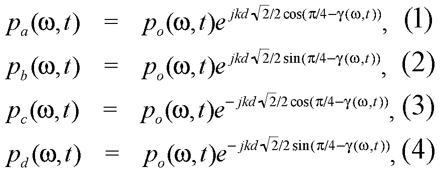
Let us consider a plane wave arriving from the direction y ((0, t) on the horizontal plane with respect to the center of the cube. If the pressure at the centre due to this plane wave is po ((S>, t) , then the pressure signals pa, pb, pc, pd recorded by the four microphones 120a, 120b, 120c, 120d can be written as ,
Figure imgf000009_0001
where k is the wave number related to the wavelength λ as k = 2π/λ , j is the imaginary unit and d is the length of the one side of the cube. Using these four pressure signals , B-format signals , pw , px and pY can be obtained as :
Figure imgf000009_0002
If, kd« 1 , ie when the microphones are positioned close to each other in comparison to the wavelength, it can be shown by using the relations cos( cosy) ~ 1 , cos( sin y) ~ 1 , sin (kd cosy) ~ kd cosy and sin (kd sin γ ) ~ kd sin γ that ,
Figure imgf000009_0003
px (ω, = j2p0 (ω, f)kd cos(y(ro, f)
pY (ω, = j2p0 (ω, t)kd ¾η(γ(ω, 0)
The acoustic particle velocity, v(r,w,t) , instantaneous intensity, and direction of the intensity vector, y((0,t) can be obtained from px, py, and pw.
Since the microphones 120a, 120b, 120c, 120d in the array are closely spaced, plane wave assumption can safely be made for incident waves and their directions can be calculated. If simultaneously active sound signals do not overlap directionally in short time-frequency windows , the directions of the intensity vectors correspond to those of the sound sources randomly shifted by major reflections .
The exhaustive separation of the sources by decomposing the sound field into plane waves using intensity vector directions will now be described. This essentially comprises taking N possible directions , and identifying from which of those possible directions the sound is coming , which indicates the likely positions of the sources .
In a short time-frequency window , the pressure signal pw ((S>, t) can be written as the sum of pressure waves arriving from all directions , independent of the number of sound sources . Then, a crude approximation of the plane wave (μ,(ύ, ί) arriving from direction μ can be obtained by spatial filtering pw (i , t) as ,
?(μ, ω, = pw (ω, t)f( (ω, t); μ, κ), (8) where f(y ((0, t); μ,κ) is the directional filter defined by the von Mises function, which is the circular equivalent of the Gaussian function.
Spatial filtering involves, for each possible source direction or ' look direction' multiplying each frequency component by a factor which varies (as defined by the filter) with the difference between the look direction and the direction from which the frequency component is detected as coming .
For exhaustive separation, ie separation of the mixture between a total set of N possible source directions , N directional filters are used with look directions μ varied by 2n/N intervals . Then, the spatial filtering yields a row vector ϊ of size N for each time-frequency component : s (ω, t) =
Figure imgf000011_0001
where (ω, ί) = /(γ(ω, ; μ,,κ) .
The elements of this vector can be considered as the proportion of the frequency component that is detected as coming from each of the N possibe source directions .
This method implies block-based processing, such as with the overlap-add technique. The recorded signals are windowed, ie divided into time periods or windows of equal length, and converted into frequency domain after which each sample is processed as in (9) . These are then converted back into time-domain, windowed with a matching window function, overlapped and added to remove block effects. Due to the 3D symmetry of the tetrahedral microphone array of Figure 2, the pressure gradient along the z axis, Pz ) can also be calculated and used for estimating both the horizontal and the vertical directions of the intensity vectors. The active intensity in 3D can be written as:
Figure imgf000011_0002
Then, the horizontal and vertical directions of the intensity vector, ■> ) and
, respectively, can be obtained by Re{pw * ((o, t)pY ((o, t)}
μ(ω, ί) = arctan
Re{pw (&, t)Px (&, t)}
(11)
Re{pw * ((a, t)pz ((a, t)}
v (ω, t) = arctan
(Re{pw * (ω, t)Px (ω, t)}f + (Re{pw * (ω, t)pY (ω, t
(12) The extension of the von Mises distribution to 3D case yields a Fisher distribution which is defined as
/(θ,φ; μ,ν ,κ) exp[K{cos(|) cosv + βίηφ sinv cos(0 - μ)}]8ΐηφ
4π sinh κ (13) where 0 < θ < 2π and 0 < φ < π are the horizontal and vertical spherical polar coordinates and K is the concentration parameter. This distribution is also known as von Mises-Fisher distribution. For φ =π /2 (on the horizontal plane) , this distribution reduces to the simple von Mises distribution. For separation of sources in 3D, the directivity function is obtained by using this function, which then enables spatial filtering considering both the horizontal and vertical intensity vector directions.
Once the spatial filtering has been performed, sound received from one or more chosen directions can be selected and, for example, reproduced through the speaker system 14.
Even though the microphones of the array are of the type which is referred to as omnidirectional, they are generally constructed in a way such that they can be considered to face in a particular direction. Typically each microphone has a sensing surface, generally being the surface of a diaphragm, which may be flat, and may be circular or square in shape, and therefore has a geometrical centre. This forms the centre point of the sensor, which is the point at which it is nominally measuring the pressure. A line from that centre point and perpendicular to the sensing surface can be considered as the central axis of the microphone and extends in the direction in which the microphone is facing. Referring to Figure 3, in a known tetrahedral microphone array, the microphones are arranged such that each of them faces away from a common central point which is the centre of the tetrahedron. However, referring to Figure 4, in this embodiment the four microphones 120a, 120b, 120c, 120d of the array are arranged in two pairs. In each pair, the two microphones making up the pair are arranged in the same orientation as each other, so that they both face in the same direction, as indicated by the arrows in Figure 4, which is perpendicular to an imaginary line between their two centre points. The two pairs of microphones face in opposite directions, each pair facing generally away from the other pair. The positions of the microphones 120a, 120b, 120c, 120d in the array relative to each other is the same as in a tetrahedral array, with the centre point of each microphone being the same distance from the centre points of each of the other three.
Referring to Figure 5, the microphone array 120 is constructed as a planar support member 130 having two opposite support surfaces 132, 134 on opposite sides. As the support member 130 is flat and regular, the two surfaces 132, 134 are parallel to each other. One pair of microphones 120a, 120c is mounted on one of the surfaces 132 and the other pair of microphones 120b, 120d is mounted on the other of the surfaces 134. Each of the microphones 120a, 120b, 120c, 120d is a MEMS microphone and comprises a body 140 with a diaphragm 142 formed on it. The body has a rear surface which is adhered directly to the support member 130 and a front surface in which the diaphragm 142 is formed. The diaphragm 142 is circular and so has a centre point 143 at its geometrical centre as described above. The diaphragm also has rotational symmetry about a central axis 144 which extends through the centre point and perpendicular to the plane of the diaphragm. The central axis extends in the direction in which the microphone faces. The first pair of microphones 120a, 120c are mounted so that they both face in the same direction which is perpendicular to the plane of the support member 130, and the second pair of microphones 120b, 120d are mounted so that they face in the opposite direction. The spacing between the diaphragm centres of the two microphones in the first pair is the same as the spacing between the diaphragm centres of the two microphones in the second pair, and is selected so that each of the microphone centre points is equidistant from the other three.
Referring to Figure 6, in a second embodiment of the invention, the four microphones 220a, 220b, 220c, 220d are again all mounted on a common support member 230, but in this case the support member 230 is in the form of a flexible strip of sheet material. The microphones are all mounted on the same side 232 of the strip 230, but the first pair of microphones 220a, 220c is mounted on a first part 230a of the strip, and the second pair of microphones 220b, 220d is mounted on a second part 230b of the strip. The strip 230 is folded so that the two parts 230a, 230b are parallel to each other, with the side 230 on which the microphones are mounted being on the outside so that the two pairs of microphones face away from each other. The final spacing between the two parts 230a, 230b of the strip 230 is such that the diaphragm centres in the four microphones are equidistant from each other as in the previous embodiment. Referring to Figure 6a, this can be achieved by folding the support member 230 around a rigid support block 240 having parallel opposite sides and fixing the two parts 230a, 230b of the support member 230 to the opposite sides of the support block 240.
In a modification to this embodiment, the central part of the flexible strip 230 can be removed after it has been mounted on the support block, so that in the final array, the two pairs of microphones are supported on separate support members, which are themselves mounted on opposite sides of the support block 240. Figure 7 shows the two pairs of microphones mounted on the support strip 230 before the strip is folded. The strip is rectangular, and one of the pairs 220a, 220c are spaced apart in a direction transverse to the strip, and the other of the pairs 220b, 220d are spaced apart in the perpendicular direction, along the strip 230. The two pairs are spaced apart by equal distances.
Figure 8 shows a modification to the embodiment of Figure 7, in which the support strip 330 has a wide part 330a on which the transversely spaced pair of microphones is mounted, but a narrower waisted part 330b on which the longitudinally spaced microphones are mounted. This shaping of the support strip helps to reduce boundary effects produced by the strip which can interfere with the sound being detected. Figure 9 shows a further modification, in which the strip is made of two rectangular portions, a wider part 430a on which the transversely spaced pair of microphones is mounted, but a narrower part 430b on which the longitudinally spaced microphones are mounted.
In each of the embodiments of Figures 6 to 9, the microphones can be 'top ported' MEMS microphones, in which case the underside of each of the microphones is mounted on the outer surface of one of the portions of the support member, and the top surface of the microphone is arranged to detect sound waves. Alternatively, the microphones can be 'bottom ported' MEMS microphones in which case each of the microphones is mounted on the inner surface of one of the portions of the support member, and the support strip has an aperture through it for each of the microphones, through which sound waves can reach the underside of the microphone, which is arranged to detect them.
To test the effectiveness of the invention a microphone array was constructed using four omnidirectional capsule microphones (Rapidonline product code 35-0192) mounted two on each side of a rigid PCB. The microphones were cylindrical and had a diameter of 9.8 mm and a diaphragm located inside the capsule 6mm above the bottom side of the capsule, the centre of the diaphragm forming the centre point of the microphone. The PCB thickness was 1.6mm, so the separation between the plane of the microphone diaphragms on one side of the PCB and the plane of those on the other was 13.6mm. The two microphones on each side were therefore mounted facing in the same direction with their centres 13.6xV2 (19.2) mm apart in an arrangement similar to that of Figure 5, resulting in a tetrahedral spacing of the centre points. The method described above was used to measure the positions of various sound sources relative to the microphone array, and the correspondence between measured positions and the actual positions are shown in Figures 10 and 11. As can be seen, there is good correspondence between the measured and actual positions, though some inaccuracy arises, which is assumed to be due to lack of calibration of the microphones .
Referring to Figure 12, a microphone array forming part of a system of a further embodiment of the invention comprises four microphones 520a, 520b, 520c, 520d, again spaced so that the centre point of each of them is equidistant from the centre points of the three others. However, in this case a group of three of the microphones 520a, 520b, 520c all face in the same direction, and the one remaining microphone 520d faces in the opposite direction. The group of three microphones 520a, 520b, 520c, lie in a common plane, and the direction in which they face is perpendicular to that plane, and generally away from the other, fourth, microphone 520d. The fourth microphone 520d faces away from the common plane of the other three 520a, 520b, 520c. Referring to Figure 13, the array of Figure 12 is constructed using a flexible strip support member 530 similar to that of Figure 6. However in this case the group of three microphones 520a, 520b, 520c are arranged in a triangular array, each equidistant from the other two, near one end of the strip, and the fourth microphone 520d is located near the other end of the strip. Each of the microphones faces in a direction perpendicular to the surface of the strip 520 on which it is mounted. The strip is folded through 180 degrees so that the fourth microphone 520d faces in the opposite direction to the other three, and so that the sensing centre point of the fourth microphone is located equidistant from the centre points of the other three.
Referring to Figures 14 and 15 a device 600 in which the array is mounted, which in this case is a mobile phone but could be another device such as a laptop, television, netbook etc, is generally rectilinear having a front face 602 and a rear face 604 which are parallel to each other. The front and rear faces 602, 604 are both generally rectangular but have rounded corners 606. The front face 602 has a screen on it which takes up most of its surface area, and is larger than the rear face 604. The side surface 606 of the phone, which extends between the front and rear faces 602, 604, is curved. The phone 600 includes a microphone array comprising four microphones 620a, 620b, 620c, 620d arranged on a substrate in the same manner as that of Figure 13. The array is orientated so that the three microphones 620a, 620b, 620c that are on one side of the substrate and facing in the same direction are located under the front face 602 of the phone facing forwards, and the fourth microphone which faces in the opposite direction is located under the rear surface of the phone facing backwards out of the rear face. The three microphones 620a, 620b, 620c, as they are equidistant from each other, are at the corners of an equilateral triangle. Two of those microphones 620a, 620b are located close to the outer edge of the top surface 602. In this embodiment they are in the curved corner region 606, and are arranged so that the line joining them is at 45° to each of the sides that join at the corner. The third of the three microphones 620c is located equidistant from the two sides that join at the corner, on the plane of symmetry of the corner (which is perpendicular to the front and rear surfaces and at 45° to each of the sides that join at the corner) . Similar non-symmetrical arrangements can also be used.
In other embodiments, the shape of the casing of the device will be different, and therefore the exact arrangement of the microphones may be optimized for the particular device.
In other embodiments, the array of Figures 14 and 15 is arranged the other way up, so that the three microphones 620a, 620b, 620c are closer to the rear face and face backwards, and the fourth microphone 620d is near the front face and faces forwards. This has the advantage that the casing of the device, which will generally have a hole in for each of the microphones, to allow sound from outside the device to reach the microphones, will only have one hole in the front face rather than three. Where the front face of the device has a flat screen with a bezel around the edge, the one microphone under the front face can be arranged behind the line at which the bezel meets the edge of the screen. This means that, in some cases, the hole for the front microphone can be formed at the edge of the bezel. For example the edge of the hole may be formed partly by the screen and partly by the bezel. In still further embodiments, the orientation of the array can be modified in other ways to suit the individual geometry of the device to which it is fitted.
The systems described above are arranged for source separation, ie to identify the components of a sound mixture coming from each of a plurality of sources in different locations. However it will be appreciated that in other embodiments the systems can be arranged to identify components of sound from just a single direction. This can be useful in directional listening devices.

Claims

1. A system for directionally selective sound reception comprising an array of pressure sensors each arranged to output a pressure signal indicative of pressure, and processing means arranged to receive the pressure signals, identify a plurality of frequency components of the signals, identify at least one source direction, and identify at least one of the components as coming from the source direction, wherein the sensor array comprises support means having two opposite sides and four sensors, at least one of the sensors being supported on each of the sides of the support means.
2. A system according to claim 1 wherein there is a pair of the sensors supported on each of the sides, each pair comprising two sensors facing in the same direction.
3. A system according to claim 1 wherein three of the sensors are supported on one of the sides and one of the sensors is supported on the other of the sides.
4. A system according to any foregoing claim wherein the support means has two surfaces, which are parallel to each other, each of said surfaces having one of said pairs of sensors mounted on it.
5. A system according to any foregoing claim wherein the support means comprises a flat member with the two surfaces being on opposite sides of the member.
6. A system according to any of claims 1 to 4 wherein the support means comprises two sheet portions which are parallel to each other, each of the sheet portions having an outer surface which faces away from the other of the sheet portions, and an inner surface which faces towards the other of the sheet portions, the outer or inner surfaces, or at least one of each, forming the surfaces on which the sensors are mounted.
7. A system according to claim 6 wherein the sheet portions are connected to each other forming part of a single sheet member.
8. A system according to any foregoing claim wherein each of the sensors has a sensing centre point, and the sensing centre points of the four sensors are arranged such that each of them is equidistant from each of the other three.
9. A system according to claim 8 wherein each sensor comprises a diaphragm.
10. A system according to claim 9 wherein the sensing centre is the geometrical centre of the diaphragm.
11. A system according to claim 9 or claim 10 wherein the diaphragms of all four sensors are parallel to each other.
12. A device having a front face and a rear face and including a system according to any foregoing claim, wherein each of the sides of the support means is arranged parallel to one of the faces.
13. A device according to claim 12 wherein one of the front face and the rear face is formed of two components, and a hole is formed at the boundary between the two components to allow sound from outside the device to reach one of the microphones.
14. A system substantially as described herein with reference to Figures 1 , 2 and 5 of the accompanying drawings.
15. A system substantially as described herein with reference to Figures 1 , 2, 6 and 7 of the accompanying drawings.
16. A system substantially as described herein with reference to Figures 1 , 2 and 13 of the accompanying drawings.
17. A system substantially as described herein with reference to Figures 1 , 2, 14 and 15 of the accompanying drawings.
PCT/GB2013/050784 2012-03-26 2013-03-26 Acoustic source separation WO2013144609A1 (en)

Priority Applications (3)

Application Number Priority Date Filing Date Title
KR1020147030026A KR102049620B1 (en) 2012-03-26 2013-03-26 Directional Sound Receiving System
EP13715404.3A EP2832111B1 (en) 2012-03-26 2013-03-26 Acoustic source separation
US14/388,280 US9473841B2 (en) 2012-03-26 2013-03-26 Acoustic source separation

Applications Claiming Priority (4)

Application Number Priority Date Filing Date Title
GB1205289.0 2012-03-26
GBGB1205289.0A GB201205289D0 (en) 2012-03-26 2012-03-26 Acoustic source separation
GB1223091.8 2012-12-20
GBGB1223091.8A GB201223091D0 (en) 2012-12-20 2012-12-20 Acoustic source separation

Publications (1)

Publication Number Publication Date
WO2013144609A1 true WO2013144609A1 (en) 2013-10-03

Family

ID=48083554

Family Applications (1)

Application Number Title Priority Date Filing Date
PCT/GB2013/050784 WO2013144609A1 (en) 2012-03-26 2013-03-26 Acoustic source separation

Country Status (4)

Country Link
US (1) US9473841B2 (en)
EP (1) EP2832111B1 (en)
KR (1) KR102049620B1 (en)
WO (1) WO2013144609A1 (en)

Cited By (1)

* Cited by examiner, † Cited by third party
Publication number Priority date Publication date Assignee Title
US9774953B2 (en) 2013-04-29 2017-09-26 University Of Surrey Microphone array for acoustic source separation

Families Citing this family (25)

* Cited by examiner, † Cited by third party
Publication number Priority date Publication date Assignee Title
CA2975955A1 (en) * 2015-02-13 2016-08-18 Noopl, Inc. System and method for improving hearing
US9565493B2 (en) 2015-04-30 2017-02-07 Shure Acquisition Holdings, Inc. Array microphone system and method of assembling the same
US9554207B2 (en) 2015-04-30 2017-01-24 Shure Acquisition Holdings, Inc. Offset cartridge microphones
US9838646B2 (en) * 2015-09-24 2017-12-05 Cisco Technology, Inc. Attenuation of loudspeaker in microphone array
WO2017218399A1 (en) * 2016-06-15 2017-12-21 Mh Acoustics, Llc Spatial encoding directional microphone array
US10477304B2 (en) 2016-06-15 2019-11-12 Mh Acoustics, Llc Spatial encoding directional microphone array
US10367948B2 (en) 2017-01-13 2019-07-30 Shure Acquisition Holdings, Inc. Post-mixing acoustic echo cancellation systems and methods
JP6878974B2 (en) * 2017-03-16 2021-06-02 株式会社リコー Imaging device, imaging system
EP3804356A1 (en) * 2018-06-01 2021-04-14 Shure Acquisition Holdings, Inc. Pattern-forming microphone array
US11297423B2 (en) 2018-06-15 2022-04-05 Shure Acquisition Holdings, Inc. Endfire linear array microphone
EP3854108A1 (en) 2018-09-20 2021-07-28 Shure Acquisition Holdings, Inc. Adjustable lobe shape for array microphones
US11558693B2 (en) 2019-03-21 2023-01-17 Shure Acquisition Holdings, Inc. Auto focus, auto focus within regions, and auto placement of beamformed microphone lobes with inhibition and voice activity detection functionality
CN113841419A (en) 2019-03-21 2021-12-24 舒尔获得控股公司 Housing and associated design features for ceiling array microphone
JP2022526761A (en) 2019-03-21 2022-05-26 シュアー アクイジッション ホールディングス インコーポレイテッド Beam forming with blocking function Automatic focusing, intra-regional focusing, and automatic placement of microphone lobes
CN114051738A (en) 2019-05-23 2022-02-15 舒尔获得控股公司 Steerable speaker array, system and method thereof
CN114051637A (en) 2019-05-31 2022-02-15 舒尔获得控股公司 Low-delay automatic mixer integrating voice and noise activity detection
JP2022545113A (en) 2019-08-23 2022-10-25 シュアー アクイジッション ホールディングス インコーポレイテッド One-dimensional array microphone with improved directivity
WO2021040667A1 (en) * 2019-08-28 2021-03-04 Orta Dogu Teknik Universitesi Spherically steerable vector differential microphone arrays
CN112788479B (en) * 2019-11-11 2023-03-24 阿里巴巴集团控股有限公司 Pickup array, pickup device and pickup performance optimization method
US11552611B2 (en) 2020-02-07 2023-01-10 Shure Acquisition Holdings, Inc. System and method for automatic adjustment of reference gain
KR102153106B1 (en) * 2020-02-12 2020-09-07 한국영상대학교 산학협력단 Modular Microphone
USD944776S1 (en) 2020-05-05 2022-03-01 Shure Acquisition Holdings, Inc. Audio device
WO2021243368A2 (en) 2020-05-29 2021-12-02 Shure Acquisition Holdings, Inc. Transducer steering and configuration systems and methods using a local positioning system
US11785380B2 (en) 2021-01-28 2023-10-10 Shure Acquisition Holdings, Inc. Hybrid audio beamforming system
US11636842B2 (en) * 2021-01-29 2023-04-25 Iyo Inc. Ear-mountable listening device having a microphone array disposed around a circuit board

Citations (4)

* Cited by examiner, † Cited by third party
Publication number Priority date Publication date Assignee Title
US7058184B1 (en) * 2003-03-25 2006-06-06 Robert Hickling Acoustic measurement method and apparatus
WO2009050487A1 (en) 2007-10-19 2009-04-23 The University Of Surrey Acoustic source separation
US20110123058A1 (en) * 2008-04-28 2011-05-26 Gerwin Hermanus Gelinck Composite microphone, microphone assembly and method of manufacturing those
US20120051548A1 (en) * 2010-02-18 2012-03-01 Qualcomm Incorporated Microphone array subset selection for robust noise reduction

Family Cites Families (8)

* Cited by examiner, † Cited by third party
Publication number Priority date Publication date Assignee Title
JP4722347B2 (en) 2000-10-02 2011-07-13 中部電力株式会社 Sound source exploration system
US7142682B2 (en) 2002-12-20 2006-11-28 Sonion Mems A/S Silicon-based transducer for use in hearing instruments and listening devices
US7542580B2 (en) 2005-02-25 2009-06-02 Starkey Laboratories, Inc. Microphone placement in hearing assistance devices to provide controlled directivity
US20070047742A1 (en) 2005-08-26 2007-03-01 Step Communications Corporation, A Nevada Corporation Method and system for enhancing regional sensitivity noise discrimination
CH702399B1 (en) 2009-12-02 2018-05-15 Veovox Sa Apparatus and method for capturing and processing the voice
US20110200205A1 (en) 2010-02-17 2011-08-18 Panasonic Corporation Sound pickup apparatus, portable communication apparatus, and image pickup apparatus
US9025782B2 (en) 2010-07-26 2015-05-05 Qualcomm Incorporated Systems, methods, apparatus, and computer-readable media for multi-microphone location-selective processing
EP2992687B1 (en) * 2013-04-29 2018-06-06 University Of Surrey Microphone array for acoustic source separation

Patent Citations (4)

* Cited by examiner, † Cited by third party
Publication number Priority date Publication date Assignee Title
US7058184B1 (en) * 2003-03-25 2006-06-06 Robert Hickling Acoustic measurement method and apparatus
WO2009050487A1 (en) 2007-10-19 2009-04-23 The University Of Surrey Acoustic source separation
US20110123058A1 (en) * 2008-04-28 2011-05-26 Gerwin Hermanus Gelinck Composite microphone, microphone assembly and method of manufacturing those
US20120051548A1 (en) * 2010-02-18 2012-03-01 Qualcomm Incorporated Microphone array subset selection for robust noise reduction

Non-Patent Citations (1)

* Cited by examiner, † Cited by third party
Title
BENJAMIN ERIC ET AL: "The Native B-Format Microphone", AES CONVENTION 119; OCTOBER 2005, AES, 60 EAST 42ND STREET, ROOM 2520 NEW YORK 10165-2520, USA, 1 October 2005 (2005-10-01), XP040507438 *

Cited By (1)

* Cited by examiner, † Cited by third party
Publication number Priority date Publication date Assignee Title
US9774953B2 (en) 2013-04-29 2017-09-26 University Of Surrey Microphone array for acoustic source separation

Also Published As

Publication number Publication date
EP2832111A1 (en) 2015-02-04
EP2832111B1 (en) 2018-05-23
US9473841B2 (en) 2016-10-18
US20150055796A1 (en) 2015-02-26
KR20150107589A (en) 2015-09-23
KR102049620B1 (en) 2019-11-27

Similar Documents

Publication Publication Date Title
EP2832111B1 (en) Acoustic source separation
US9774953B2 (en) Microphone array for acoustic source separation
US20230262381A1 (en) Microphone Array System
CN112335261A (en) Pattern forming microphone array
EP2628316B1 (en) Apparatus and method for deriving a directional information and computer program product
US8472639B2 (en) Microphone arrangement having more than one pressure gradient transducer
CN101855914B (en) Position determination of sound sources
Jackson et al. Sound field planarity characterized by superdirective beamforming
Derkx et al. Theoretical analysis of a first-order azimuth-steerable superdirective microphone array
US11792566B2 (en) Directional microphone and system and method for capturing and processing sound
Ding et al. DOA estimation of multiple speech sources by selecting reliable local sound intensity estimates
Itzhak et al. Region-of-Interest Oriented Constant-Beamwidth Beamforming with Rectangular Arrays
US11671751B2 (en) Microphone array
Andráš et al. Beamforming with small diameter microphone array
De Bree et al. A single broad banded 3D beamforming sound probe
Stern et al. " polyaural" array processing for automatic speech recognition in degraded environments.
CN108156545A (en) A kind of array microphone
Papež et al. Enhanced MVDR beamforming for mems microphone array
Lawrence et al. Highly directional pressure sensing using the phase gradient
Ono et al. Sound Source Localization with Front-Back Judgement by Two Microphones Asymmetrically Mounted on a Sphere.
Farahikia et al. Effects of geometry dependent diffraction on the performance of object-mounted Linear Differential Microphone Arrays
Gillett et al. Performance benefits of spherical diffracting arrays versus free field arrays
Carneal et al. Comparison of a diffracting and a non-diffracting circular acoustic array
Luo et al. On the Design of Planar Differential Microphone Arrays with Specified Beamwidth or Sidelobe Level
Itzhak et al. Kronecker-Product Beamforming with Sparse Concentric Circular Arrays

Legal Events

Date Code Title Description
121 Ep: the epo has been informed by wipo that ep was designated in this application

Ref document number: 13715404

Country of ref document: EP

Kind code of ref document: A1

NENP Non-entry into the national phase

Ref country code: DE

WWE Wipo information: entry into national phase

Ref document number: 14388280

Country of ref document: US

WWE Wipo information: entry into national phase

Ref document number: 2013715404

Country of ref document: EP

ENP Entry into the national phase

Ref document number: 20147030026

Country of ref document: KR

Kind code of ref document: A