WO2013136831A1 - Base station, terminals, communication system, communication method and integrated circuit - Google Patents
Base station, terminals, communication system, communication method and integrated circuit Download PDFInfo
- Publication number
- WO2013136831A1 WO2013136831A1 PCT/JP2013/050518 JP2013050518W WO2013136831A1 WO 2013136831 A1 WO2013136831 A1 WO 2013136831A1 JP 2013050518 W JP2013050518 W JP 2013050518W WO 2013136831 A1 WO2013136831 A1 WO 2013136831A1
- Authority
- WO
- WIPO (PCT)
- Prior art keywords
- control channel
- terminal
- extended
- resource
- mapping
- Prior art date
Links
Images


Classifications
-
- H—ELECTRICITY
- H04—ELECTRIC COMMUNICATION TECHNIQUE
- H04L—TRANSMISSION OF DIGITAL INFORMATION, e.g. TELEGRAPHIC COMMUNICATION
- H04L5/00—Arrangements affording multiple use of the transmission path
- H04L5/003—Arrangements for allocating sub-channels of the transmission path
- H04L5/0048—Allocation of pilot signals, i.e. of signals known to the receiver
- H04L5/0051—Allocation of pilot signals, i.e. of signals known to the receiver of dedicated pilots, i.e. pilots destined for a single user or terminal
-
- H—ELECTRICITY
- H04—ELECTRIC COMMUNICATION TECHNIQUE
- H04L—TRANSMISSION OF DIGITAL INFORMATION, e.g. TELEGRAPHIC COMMUNICATION
- H04L5/00—Arrangements affording multiple use of the transmission path
- H04L5/003—Arrangements for allocating sub-channels of the transmission path
- H04L5/0053—Allocation of signaling, i.e. of overhead other than pilot signals
-
- H—ELECTRICITY
- H04—ELECTRIC COMMUNICATION TECHNIQUE
- H04W—WIRELESS COMMUNICATION NETWORKS
- H04W72/00—Local resource management
- H04W72/20—Control channels or signalling for resource management
- H04W72/23—Control channels or signalling for resource management in the downlink direction of a wireless link, i.e. towards a terminal
-
- H—ELECTRICITY
- H04—ELECTRIC COMMUNICATION TECHNIQUE
- H04L—TRANSMISSION OF DIGITAL INFORMATION, e.g. TELEGRAPHIC COMMUNICATION
- H04L5/00—Arrangements affording multiple use of the transmission path
- H04L5/0001—Arrangements for dividing the transmission path
- H04L5/0003—Two-dimensional division
- H04L5/0005—Time-frequency
- H04L5/0007—Time-frequency the frequencies being orthogonal, e.g. OFDM(A), DMT
- H04L5/001—Time-frequency the frequencies being orthogonal, e.g. OFDM(A), DMT the frequencies being arranged in component carriers
-
- H—ELECTRICITY
- H04—ELECTRIC COMMUNICATION TECHNIQUE
- H04L—TRANSMISSION OF DIGITAL INFORMATION, e.g. TELEGRAPHIC COMMUNICATION
- H04L5/00—Arrangements affording multiple use of the transmission path
- H04L5/0001—Arrangements for dividing the transmission path
- H04L5/0014—Three-dimensional division
- H04L5/0023—Time-frequency-space
-
- H—ELECTRICITY
- H04—ELECTRIC COMMUNICATION TECHNIQUE
- H04L—TRANSMISSION OF DIGITAL INFORMATION, e.g. TELEGRAPHIC COMMUNICATION
- H04L5/00—Arrangements affording multiple use of the transmission path
- H04L5/0091—Signaling for the administration of the divided path
- H04L5/0092—Indication of how the channel is divided
Definitions
- the present invention relates to a base station, a terminal, a communication system, a communication method, and an integrated circuit.
- WirelessMA LAN wideXLAN, wideband
- WCDMA Wideband Code Division Multiple Access
- 3GPP Third Generation Partnership Project
- LTE Long Term Evolution
- LTE-A Long Term Evolution-Advanced
- IEEE The Institute of Electrical Electronics and Electronics Electronics engineers
- a wireless communication system such as Interoperability (for Microwave Access)
- base stations cells, transmitting stations, transmitting devices, eNodeBs
- terminals mobile terminals, receiving stations, mobile stations, receiving devices, UEs (User Equipment)
- the transmission / reception antennas are respectively provided, and by using MIMO (Multi-Input-Multi-Output) technology, data signals are spatially multiplexed to realize high-speed data communication.
- MIMO Multi-Input-Multi-Output
- a base station transmits downlink data (a transport block for a downlink shared channel (DL-SCH)) to a terminal
- the base station is connected between the base station and the terminal.
- 2 multiplexes and transmits a demodulation reference signal (also referred to as DMRS; also referred to as Demodulation Reference Signals).
- the demodulation reference signal is also referred to as a user equipment specific reference signal (UE-specific RS, terminal-specific (specific) RS).
- UE-specific RS user equipment specific reference signal
- RS terminal-specific (specific) RS
- the demodulation reference signal is also simply referred to as a reference signal.
- the reference signal is multiplexed with the downlink data before the precoding process is applied. Therefore, the terminal can measure the equalization channel including the applied precoding process and transmission path state by using the reference signal. That is, the terminal can demodulate the downlink data without being notified of the precoding process applied by the base station.
- the downlink data is mapped to a physical downlink shared channel (PDSCH; Physical Downlink Shared Channel). That is, the reference signal is used for demodulation of PDSCH. Further, for example, the reference signal is transmitted only in a resource block (also referred to as a physical resource block or a resource) to which the corresponding PDSCH is mapped.
- PDSCH Physical Downlink Shared Channel
- FIG. 11 is a schematic diagram of a wireless communication system using a heterogeneous network arrangement.
- the heterogeneous network includes macro base stations 1101, RRH 1102, and RRH 1103.
- the macro base station 1101 constructs the coverage 1105, and the RRH 1102 and the RRH 1103 construct the coverage 1106 and the coverage 1107, respectively.
- the macro base station 1101 is connected to the RRH 1102 through the line 1108 and is connected to the RRH 1103 through the line 1109. Thereby, the macro base station 1101 can transmit and receive data signals and control signals (control information) to and from the RRH 1102 and the RRH 1103.
- a wired line such as an optical fiber or a wireless line using relay technology is used for the line 1108 and the line 1109.
- a part or all of the macro base stations 1101, RRH 1102, and RRH 1103 use the same resource, thereby improving the overall frequency utilization efficiency (transmission capacity) in the area of the coverage 1105.
- the terminal 1104 when the terminal 1104 is located in the coverage 1106, the terminal 1104 can perform single cell communication with the RRH 1102. Further, when the terminal 1104 is located near the end of the coverage 1106 (cell edge), it is necessary to take measures against interference of the same channel from the macro base station 1101.
- multi-cell communication cooperative communication
- a method of reducing or suppressing interference with the terminal 1104 in the cell edge region by performing inter-base station cooperative communication between adjacent base stations Is being considered.
- a CoMP (Cooperative Multipoint) transmission system has been studied as a system for reducing or suppressing interference by cooperative communication between base stations (Non-patent Document 1).
- the present invention has been made in view of the above problems, and an object of the present invention is to provide a base station and a terminal that can efficiently notify control information for the terminal in the communication system in which the base station and the terminal communicate.
- a communication system, a communication method, and an integrated circuit are provided.
- a communication system includes a resource block pair configured by using a plurality of resource elements defined by time and frequency.
- a communication system in which one or more base station apparatuses and terminals communicate with each other, wherein the extended physical control channel is composed of one or more extended control channel elements, and the extended control channel elements include a plurality of extended control channel elements.
- the extended resource element group is mapped to each of the resource elements, and the mapping is performed for each of the resource elements except for the resource element in which a demodulation reference signal is arranged.
- a number assigned to the resource element, the extended resource element A distributed mapping in which each of the extended control channel elements is mapped to a plurality of resource block pairs, or each of the extended control channel elements is assigned to one resource block pair.
- a local mapping to be mapped can be used, and the number indicating the extended resource element group assigned to the resource element is common regardless of the distributed mapping or the local mapping, and the base station apparatus
- a terminal-specific control channel generation unit that generates the extended physical control channel based on the mapping; and a transmission unit that transmits the generated extended physical control channel.
- the extended physical control channel A control channel processing unit for receiving.
- each resource block pair includes 16 extended resource element groups.
- the base station uses one or more resource block pairs configured by using a plurality of resource elements defined by time and frequency, and communicates with a terminal.
- the extended physical control channel includes one or more extended control channel elements, the extended control channel element includes a plurality of extended resource element groups, and the extended resource element group includes the resource.
- Each of the elements is mapped, and the mapping is a number assigned to each resource element except for the resource element in which a demodulation reference signal is arranged, and indicates the extended resource element group
- Each of the extended control channels Distributed mapping in which elements are mapped to a plurality of the resource block pairs or local mapping in which each of the extended control channel elements is mapped to one resource block pair can be used.
- the number indicating the extended resource element group assigned to the resource element regardless of mapping is the same, and a terminal-specific control channel generating unit that generates the extended physical control channel based on the mapping, and generation A transmission unit for transmitting the extended physical control channel.
- each of the resource block pairs includes 16 extended resource element groups.
- the communication method is a base station apparatus that communicates with a terminal using one or more resource block pairs configured by using a plurality of resource elements defined by time and frequency.
- the extended physical control channel is composed of one or more extended control channel elements, the extended control channel element is composed of a plurality of extended resource element groups, and the extended resource element group is Are mapped to each of the resource elements, and the mapping is a number assigned to each of the resource elements except for the resource element in which a demodulation reference signal is arranged, and the extended resource element Use numbers to indicate groups, and individual A distributed mapping in which an extended control channel element is mapped to a plurality of the resource block pairs or a local mapping in which each of the extended control channel elements is mapped to a single resource block pair can be used.
- the number indicating the extended resource element group assigned to the resource element irrespective of mapping or the local mapping is common, and the extended physical control channel is generated based on the mapping.
- An extended physical control channel is transmitted to the terminal.
- each resource block pair includes 16 extended resource element groups.
- a terminal is a terminal that communicates with a base station apparatus using one or more resource block pairs configured by using a plurality of resource elements defined by time and frequency.
- the extended physical control channel includes one or more extended control channel elements, the extended control channel element includes a plurality of extended resource element groups, and the extended resource element group includes the resource elements.
- the mapping is a number assigned to each resource element except for the resource element in which a demodulation reference signal is arranged, and indicating the extended resource element group.
- each said extended control channel A distributed mapping in which elements are mapped to a plurality of the resource block pairs, or a local mapping in which each of the extended control channel elements is mapped to one resource block pair, can be used, the distributed mapping or the local The number indicating the extended resource element group assigned to the resource element regardless of mapping is common, and the extended physical control channel generated and transmitted by the base station apparatus based on the mapping And a control channel processing unit for receiving based on the mapping.
- each resource block pair includes 16 extended resource element groups.
- the processing method is a terminal that communicates with a base station apparatus using one or more resource block pairs configured by using a plurality of resource elements defined by time and frequency.
- the extended physical control channel is composed of one or more extended control channel elements
- the extended control channel element is composed of a plurality of extended resource element groups
- the extended resource element group is Are mapped to each of the resource elements
- the mapping is a number assigned to each of the resource elements except for the resource element in which a demodulation reference signal is arranged
- the extended resource element Use numbers to indicate groups, and individual A distributed mapping in which an extended control channel element is mapped to a plurality of the resource block pairs or a local mapping in which each of the extended control channel elements is mapped to a single resource block pair can be used.
- the number indicating the extended resource element group assigned to the resource element irrespective of mapping or the local mapping is common, and the extended physical generated and transmitted by the base station based on the mapping A control channel is received based on the mapping.
- each resource block pair includes 16 extended resource element groups.
- the base station in a wireless communication system in which a base station and a terminal communicate, can efficiently notify control information for the terminal.
- FIG. 1 is a schematic diagram of a wireless communication system using a heterogeneous network arrangement.
- the communication system includes a base station (transmitting device, cell, transmission point, transmitting antenna group, transmitting antenna port group, component carrier, eNodeB) and terminal (terminal device, mobile terminal, receiving point, receiving terminal). , Receiving device, receiving antenna group, receiving antenna port group, UE).
- the base station 100 transmits control information and information data through the downlink in order to perform data communication with the terminal 200.
- control information is subjected to error detection coding processing and the like, and is mapped to the control channel.
- the control channel (PDCCH) is subjected to error correction coding processing and modulation processing, and is different from the first control channel (first physical control channel) region or the first control channel region. Transmission / reception is performed via two control channel (second physical control channel) regions.
- the physical control channel referred to here is a kind of physical channel and is a control channel defined on a physical frame.
- a control channel mapped to the first control channel region is also referred to as a first control channel
- a control channel mapped to the second control channel region is also referred to as a second control channel.
- the first control channel is also referred to as PDCCH
- E-PDCCH EnhancedEnhancePDCCH
- the first control channel is a physical control channel that uses the same transmission port (antenna port) as the cell-specific reference signal.
- the second control channel is a physical control channel that uses the same transmission port as the terminal-specific reference signal.
- the terminal 200 demodulates the first control channel using the cell-specific reference signal, and demodulates the second control channel using the terminal-specific reference signal.
- the cell-specific reference signal is a reference signal common to all terminals in the cell, and is a reference signal that can be used by any terminal because it is inserted into almost all resources. Therefore, any terminal can demodulate the first control channel.
- the terminal-specific reference signal is a reference signal inserted only in the allocated resource, and can perform adaptively precoding processing and beamforming processing in the same way as data.
- the control channel arranged in the second control channel region can obtain adaptive precoding, beamforming gain, and frequency scheduling gain.
- the terminal-specific reference signal can be shared by a plurality of terminals. For example, when a control channel arranged in the second control channel region is notified by being distributed to a plurality of resources (for example, resource blocks), the terminal-specific reference signal in the second control channel region is a plurality of Can be served by the terminal.
- the control channel arranged in the second control channel region in that case can obtain a frequency diversity gain.
- the control channel (first control channel) mapped to the first control channel region is a physical control channel on an OFDM symbol (symbol) located at the front of the physical subframe. , And can be arranged over the entire system bandwidth (component carrier (CC)) on these OFDM symbols.
- the control channel (second control channel) mapped to the second control channel region is a physical control channel on the OFDM symbol located behind the first control channel of the physical subframe, and these It may be arranged in a part of the system bandwidth on the OFDM symbol. Since the first control channel is arranged on the OFDM symbol dedicated to the control channel located in the front part of the physical subframe, it can be received and demodulated before the rear OFDM symbol for the physical data channel.
- a terminal that monitors only the OFDM symbol dedicated to the control channel can also be received. Moreover, since it can be spread and arranged throughout the CC, inter-cell interference can be randomized.
- the first control channel region is a region that is set unique to the base station 100 and is a region that is common to all terminals connected to the base station 100.
- the second control channel is arranged on the rear OFDM symbol for the shared channel (physical data channel) normally received by the communicating terminal. Also, by frequency division multiplexing, the second control channels or the second control channel and the physical data channel can be orthogonally multiplexed (multiplexing without interference).
- the second control channel region is a region set for each terminal 200 and is set for each terminal connected to the base station 100.
- the base station 100 can set the second control channel region to be shared by a plurality of terminals. Further, the first control channel region and the second control channel region are arranged in the same physical subframe.
- the OFDM symbol is a unit in the time direction for mapping bits of each channel.
- the first control channel is a cell-specific physical control channel, which is a physical channel that can be acquired (detected) by both idle and connected terminals.
- the second control channel is a terminal-specific physical control channel, and is a physical channel that can be acquired only by a connected terminal.
- the idle state refers to a state in which the base station does not accumulate RRC (Radio Resource Control) information (RRC_IDLE state) or a state in which the mobile station is performing intermittent reception (DRX). This is a state where no operation is performed.
- RRC Radio Resource Control
- the connected state is a state in which data can be immediately transmitted / received, such as a state in which the terminal holds network information (RRC_CONNECTED state) or a state in which the mobile station is not performing intermittent reception (DRX).
- the first control channel is a channel that can be received by the terminal without depending on terminal-specific RRC signaling.
- the second control channel is a channel configured by terminal-specific RRC signaling, and is a channel that can be received by the terminal by terminal-specific RRC signaling.
- the first control channel is a channel that can be received by any terminal by setting limited in advance
- the second control channel is a channel in which the terminal-specific setting can be easily changed.
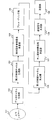
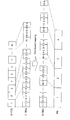
- FIG. 1 is a schematic block diagram showing the configuration of the base station 100 according to the first embodiment of the present invention.
- the base station 100 includes an upper layer 101, a data channel generation unit 102, a second control channel generation unit 103, a terminal-specific reference signal multiplexing unit 104, a precoding unit 105, a first control channel generation unit 106, A cell-specific reference signal multiplexing unit 107, a transmission signal generation unit 108, and a transmission unit 109 are provided.
- the upper layer 101 generates information data (transport block, codeword) for the terminal 200 and outputs it to the data channel region allocation unit 102.
- the information data can be a unit for performing error correction coding processing.
- the information data can be a unit for performing retransmission control such as HARQ (HybridbrAutomatic Repeat reQuest).
- the base station 100 can transmit a plurality of information data to the terminal 200.
- the data channel generation unit (data channel region allocation unit, data channel mapping unit, shared channel generation unit) 102 performs adaptive control on the information data output from the upper layer 101 and performs data channel (shared channel, A shared channel, PDSCH; Physical Downlink Shared Channel) is generated.
- the adaptive control in the data channel generation unit 102 is to use an encoding process for performing error correction encoding, a scramble process for applying a scramble code unique to the terminal 200, a multi-level modulation method, and the like.
- a layer mapping process for performing spatial multiplexing such as modulation processing and MIMO is performed.
- the layer mapping process in the data channel generation unit 102 maps to one or more layers (streams) based on the number of ranks set for the terminal 200.
- the second control channel generation unit (second control channel region allocation unit, second control channel mapping unit, terminal-specific control channel generation unit) 103 is configured so that the base station 100 uses the second control channel region (terminal-specific control channel).
- a control channel to be transmitted via the second control channel region is generated.
- the data channel generation unit 102 and the second control channel generation unit 103 are also referred to as a shared channel region allocation unit.
- the data channel and / or the second control channel is also referred to as a shared channel.
- the second control channel is also referred to as E-PDCCH (Enhanced PDCCH) or terminal-specific control channel.
- Terminal-specific reference signal multiplexing section (terminal-specific reference signal generation section, terminal-specific control channel demodulation reference signal multiplexing section, terminal-specific control channel demodulation reference signal generation section) 104 is a terminal-specific reference signal (data Channel demodulation reference signal, second control channel demodulation reference signal, shared channel demodulation reference signal, terminal-specific control channel demodulation reference signal, DM-RS (Demodulation Reference Signal), DRS (Dedicated Reference Signal), Precoded RS UE-specific RS) and multiplex the terminal-specific reference signal in the shared channel region.
- Terminal specific reference signal multiplexing section 104 receives an initial value for generating a scramble code constituting the terminal specific reference signal.
- the terminal-specific reference signal multiplexing unit 104 generates a terminal-specific reference signal based on the input initial value of the scramble code.
- the terminal-specific reference signal is set based on the data channel or the second control channel to be multiplexed, and multiplexed on each layer (antenna port) of the data channel or the second control channel.
- the terminal-specific reference signal is preferably orthogonal and / or quasi-orthogonal between layers. Note that the terminal-specific reference signal multiplexing unit 104 may generate a terminal-specific reference signal and multiplex it in the transmission signal generation unit 108 described later.
- the precoding unit 105 performs precoding processing on the data channel, the second control channel, and / or the terminal specific reference signal output from the terminal specific reference signal multiplexing unit 104.
- the precoding process may be different depending on whether the terminal-specific reference signal is used by a plurality of terminals or the terminal-specific reference signal is used by one terminal.
- the precoding process it is preferable to perform phase rotation and / or amplitude control on the input signal so that the terminal 200 can efficiently receive the precoding process.
- the precoding process is preferably performed so that the reception power of terminal 200 is maximized, interference from the adjacent cell is reduced, or interference to the adjacent cell is reduced.
- processing by a predetermined precoding matrix CDD (Cyclic Delay Delay Diversity), transmit diversity (SFBC (Spatial Frequency Block Code), STBC (Spatial Time Block Block Code), TSTD (Time Switched Transmission Diversity), FSTD (Frequency Switched) Transmission Diversity) etc.
- CDD Cyclic Delay Delay Diversity
- SFBC Spatial Frequency Block Code
- STBC Spatial Time Block Block Code
- TSTD Time Switched Transmission Diversity
- FSTD Frequency Switched Transmission Diversity
- the precoding process preferably uses a process based on a precoding matrix determined in advance, CDD, and transmission diversity.
- base station 100 feeds back a plurality of types of PMI (Precoding Matrix Indicator), which is feedback information about precoding processing, from terminal 200
- PMI Precoding Matrix Indicator
- base station 100 Precoding processing can be performed based on the result of performing arithmetic operations such as multiplication on a plurality of PMIs.
- the terminal-specific reference signal is a signal known to the base station 100 and the terminal 200.
- the terminal-specific reference signals are the base station 100 and the terminal 200, respectively.
- the channel condition in the downlink between and the precoding weight equalization channel by the precoding unit 105 can be estimated. That is, base station 100 does not need to notify terminal 200 of the precoding weight by precoding section 105, and can demodulate the precoded signal.
- the first control channel generation unit (first control channel region allocation unit, first control channel mapping unit, cell specific control channel generation unit) 106 is configured so that the base station 100 can control the first control channel region (cell specific control channel).
- first control channel region cell specific control channel
- the first control channel generation unit 106 is configured so that the base station 100 can control the first control channel region (cell specific control channel).
- a control channel to be transmitted via the first control channel region is generated.
- the control channel transmitted through the first control channel region is also referred to as a first control channel.
- the first control channel is also referred to as a cell-specific control channel.
- a cell-specific reference signal multiplexing unit (cell-specific reference signal generation unit) 107 is a cell known by the base station 100 and the terminal 200 in order to measure a downlink transmission path condition between the base station 100 and the terminal 200. Generate unique reference signals (reference signal for channel condition measurement, CRS (Common RS), Cell-specific RS, Non-precoded RS, cell-specific control channel demodulation reference signal, first control channel demodulation reference signal) . The generated cell-specific reference signal is multiplexed with the signal output by the first control channel generation unit 106. Note that the cell-specific reference signal multiplexing unit 107 may generate a cell-specific reference signal and multiplex it in the transmission signal generation unit 108 described later.
- CRS Common RS
- Cell-specific RS Cell-specific RS
- Non-precoded RS cell-specific control channel demodulation reference signal
- first control channel demodulation reference signal first control channel demodulation reference signal
- the generated cell-specific reference signal is multiplexed with the signal output by the
- any signal can be used as the cell-specific reference signal as long as both the base station 100 and the terminal 200 are known signals.
- a random number or a pseudo noise sequence based on parameters assigned in advance such as a number (cell ID) unique to the base station 100 can be used.
- a method of orthogonalizing between antenna ports a method in which resource elements for mapping cell-specific reference signals are mutually null (zero) between antenna ports, a method of code division multiplexing using a pseudo-noise sequence, or a combination thereof The method etc. can be used.
- the cell-specific reference signal may not be multiplexed in all subframes, and may be multiplexed only in some subframes.
- the cell-specific reference signal is a reference signal that is multiplexed after the precoding process by the precoding unit 105. Therefore, terminal 200 can measure a downlink transmission path condition between base station 100 and terminal 200 using a cell-specific reference signal, and a signal that has not been subjected to precoding processing by precoding section 105. Can be demodulated.
- the first control channel can be demodulated by the cell-specific reference signal.
- the first control channel can be demodulated by CRS.
- the transmission signal generation unit (channel mapping unit) 108 performs mapping processing on the signal output from the cell-specific reference signal multiplexing unit 107 to the resource element of each antenna port. Specifically, the transmission signal generation unit 108 maps the data channel to the data channel region of the shared channel region, and maps the second control channel to the second control channel region of the shared channel region. Further, the transmission signal generation unit 108 maps the first control channel to a first control channel region different from the second control channel region.
- the base station 100 can map control channels addressed to a plurality of terminals in the first control channel region and / or the second control channel region. Note that the base station 100 may map the data channel to the second control channel region. For example, when the second control channel is not mapped to the second control channel region set in the terminal 200 by the base station 100, the data channel may be mapped to the second control channel region.
- the first control channel and the second control channel are a control channel to be transmitted via different resources and / or a control channel to be demodulated using different reference signals and / or the terminal 200, respectively.
- This is a control channel that can be transmitted according to different RRC states.
- Each control channel can map control information of any format.
- a format of control information that can be mapped can be defined for each control channel.
- the first control channel can map control information of all formats
- the second control channel can map control information of some formats.
- the first control channel can map control information of all formats
- the second control channel maps control information of a format including data channel allocation information using a terminal-specific reference signal. Can do.
- the PDCCH is used for notifying (designating) downlink control information (DCI; Downlink Control Information) to the terminal.
- DCI Downlink Control Information
- the downlink control information includes information on PDSCH resource allocation, information on MCS (Modulation and Coding scheme), information on scrambling identity (also referred to as scrambling link identifier), reference signal sequence identity (base sequence identity, Information on a base sequence identifier and a base sequence index).
- a plurality of formats are defined for the downlink control information transmitted on the PDCCH.
- the format of the downlink control information is also referred to as a DCI format. That is, a field for each uplink control information is defined in the DCI format.
- DCI format 1 and DCI format 1A used for scheduling one PDSCH (one PDSCH codeword, one downlink transport block transmission) in one cell are defined as DCI formats for the downlink.
- the DCI format 1 and the DCI format 1A are also used for transmission on the PDSCH by transmission diversity (TxD: Transmission Diversity) using a plurality of transmission antenna ports.
- TxD Transmission Diversity
- DCI formats for downlink DCI format 2 and DCI format used for scheduling one PDSCH (up to two PDSCH codewords, up to two downlink transport transmissions) in one cell.
- 2A and DCI format 2B and DCI format 2C are defined. That is, DCI format 2, DCI format 2A, DCI format 2B, and DCI format 2C are used for transmission on a MIMO SDM (Multiple Input Multiple Domain Multiplexing) PDSCH using a plurality of transmission antenna ports.
- MIMO SDM Multiple Input Multiple Domain Multiplexing
- the format of the control information is specified in advance.
- the control information can be defined according to the purpose of the base station 100 notifying the terminal 200.
- the control information includes downlink data channel allocation information for the terminal 200, uplink data channel (PUSCH: Physical-Uplink-Shared Channel) and control channel (PUCCH: Physical-Uplink Control Channel) for the terminal 200.
- Information, information for controlling transmission power for the terminal 200, and the like can be specified. Therefore, for example, when the base station 100 transmits downlink information data to the terminal 200, the control channel to which control information including downlink data channel allocation information for the terminal 200 is mapped, and its control A data channel to which information data assigned based on the information is mapped is transmitted.
- the base station 100 when allocating an uplink data channel to the terminal 200, transmits a control channel to which control information including uplink data channel allocation information for the terminal 200 is mapped.
- the base station 100 can transmit a plurality of different control information or the same control information to the same terminal 200 in the same subframe in different formats or the same format. Note that, when the base station 100 transmits downlink information data to the terminal 200, what is a subframe for transmitting a control channel to which control information including downlink data channel allocation information for the terminal 200 is mapped? It is also possible to transmit downlink data channels in different subframes.
- the first control channel region is a region unique to the base station 100, it is also referred to as a cell-specific control channel region.
- the second control channel region is a region specific to terminal 200 set from base station 100 through RRC signaling, and is also referred to as a terminal-specific control channel region.
- the second control channel region is set in units of regions in which two resource blocks composed of a predetermined frequency direction region and a predetermined time direction region are continuously arranged in the time direction.
- the base station 100 and the terminal 200 transmit and receive signals in an upper layer (Higher layer).
- the base station and the terminal are also referred to as a radio resource control signal (RRC signaling; Radio Resource Control signal, RRC message; Radio Resource Control message, RRC information; Radio Resource Control designation).
- RRC signaling Radio Resource Control signal
- RRC message Radio Resource Control message
- RRC information Radio Resource Control designation
- Send and receive
- a dedicated signal transmitted to a certain terminal by the base station is also referred to as a dedicated signal (dedicated signal).
- the setting (information) notified by the base station using the dedicated signal is a setting specific to a certain terminal.
- the base station and the terminal transmit and receive MAC control elements in a MAC (Media Access Control) layer (layer 2).
- MAC Media Access Control
- the RRC signaling and / or MAC control element is also referred to as an upper layer signal (Higher layer signaling).
- the transmission unit 109 performs inverse fast Fourier transform (IFFT; Inverse ⁇ ⁇ ⁇ Fourier Transform), addition of a guard interval, conversion processing to a radio frequency, etc. Transmit from the transmitting antenna.
- IFFT inverse fast Fourier transform
- ⁇ ⁇ ⁇ Fourier Transform Inverse ⁇ ⁇ ⁇ Fourier Transform
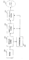
- FIG. 2 is a schematic block diagram showing the configuration of the terminal 200 according to the first embodiment of the present invention.
- terminal 200 includes reception section 201, reception signal processing section 202, propagation path estimation section 203, control channel processing section 204, data channel processing section 205, and higher layer 206.
- the receiving unit 201 receives a signal transmitted by the base station 100 using one or a plurality of receiving antennas (the number of receiving antenna ports), performs a conversion process from a radio frequency to a baseband signal, and an added guard. Time frequency conversion processing such as interval removal and Fast Fourier Transform (FFT) is performed.
- FFT Fast Fourier Transform
- the received signal processing unit 202 demaps (separates) the signal mapped by the base station 100. Specifically, the received signal processing unit 202 demaps the first control channel and / or the second control channel and / or the data channel, and outputs the demapped signal to the control channel processing unit 204. Also, received signal processing section 202 demaps the multiplexed cell-specific reference signal and / or terminal-specific reference signal and outputs the result to propagation path estimation section 203.
- the propagation path estimation unit 203 performs propagation path estimation for the resources of the first control channel and / or the second control channel and / or the data channel based on the cell-specific reference signal and / or the terminal-specific reference signal.
- the propagation path estimation unit 203 outputs the estimation result of the propagation path estimation to the control channel processing unit 204 and / or the data channel processing unit 205.
- the propagation path estimation unit 203 varies the amplitude and phase in each resource element for each reception antenna port of each transmission antenna port. (Frequency response, transfer function) is estimated (propagation channel estimation), and a channel estimation value is obtained.
- the initial value of the scramble code constituting the terminal-specific reference signal is input to the propagation path estimation unit 203, and the terminal-specific reference signal is determined based on the initial value and the like. Further, the propagation path estimation unit 203 estimates amplitude and phase fluctuations in each resource element for each reception antenna port of each transmission antenna port based on the cell-specific reference signal multiplexed on the first control channel. Then, a propagation path estimation value is obtained.
- the control channel processing unit 204 searches for a control channel addressed to the terminal 200 mapped to the first control channel region and / or the second control channel region.
- the control channel processing unit 204 sets a first control channel region and / or a second control channel region as a control channel region for searching for a control channel.
- the setting of the second control channel region is performed through higher-layer control information (for example, RRC (Radio Resource Control) signaling) that the base station 100 notifies the terminal 200 of.
- RRC Radio Resource Control
- the setting of the second control channel region is control information for setting the second control channel as the terminal-specific setting information of the second control channel, and is setting information specific to the terminal 100. Details of the setting of the second control channel region will be described later.
- the control channel processing unit 204 is mapped to the second control channel region A control channel addressed to terminal 200 is searched.
- the control channel processing unit 204 may also search for a partial region in the first control channel region.
- the control channel processing unit 204 may also search for a cell-specific search region in the first control channel region.
- the control channel processing unit 204 is mapped to the first control channel region. A control channel addressed to terminal 200 is searched.
- the control channel processing unit 204 uses a terminal-specific reference signal in order to demodulate a possible control channel.
- the control channel processing unit 204 uses a cell-specific reference signal to demodulate a possible control channel.
- control channel processing unit 204 demodulates and controls all or part of control channel candidates obtained based on the type of control information, the location of the mapped resource, the size of the mapped resource, and the like. A decoding process is performed to search sequentially.
- the control channel processing unit 204 uses an error detection code (for example, CRC (Cyclic Redundancy Check) code) added to the control information as a method for determining whether or not the control information is addressed to the terminal 200.
- CRC Cyclic Redundancy Check
- Such a search method is also called blind decoding.
- control channel processing unit 204 detects a control channel addressed to the terminal 200
- control channel processing unit 204 identifies control information mapped to the detected control channel, and is shared by the entire terminal 200 (including higher layers), and is downlinked. It is used for various controls in terminal 200 such as data channel reception processing, uplink data channel and control channel transmission processing, and uplink transmission power control.
- control channel processing unit 204 When control information including downlink data channel allocation information is mapped to the detected control channel, the control channel processing unit 204 sends the data channel demapped by the received signal processing unit 202 to the data channel processing unit 205. Output.
- the data channel processing unit 205 performs channel compensation processing (filter processing), layer demapping using the channel estimation result input from the channel estimation unit 203 on the data channel input from the control channel processing unit 204. Processing, demodulation processing, descrambling processing, error correction decoding processing, and the like are performed and output to the upper layer 206. Note that a resource element to which no terminal-specific reference signal is mapped performs channel estimation by performing interpolation or averaging in the frequency direction and the time direction based on the resource element to which the terminal-specific reference signal is mapped. In the propagation path compensation processing, propagation path compensation is performed on the input data channel using the estimated propagation path estimation value, and a signal for each layer based on the information data is detected (restored).
- the detection method it is possible to use equalization of ZF (Zero ⁇ Forcing) norm, MMSE (Minimum Mean Square Error) norm, turbo equalization, interference removal, and the like.
- ZF Zero ⁇ Forcing
- MMSE Minimum Mean Square Error
- turbo equalization turbo equalization
- interference removal and the like.
- the layer demapping process the demapping process is performed on the signal for each layer to the respective information data. The subsequent processing is performed for each information data.
- demodulation process demodulation is performed based on the modulation method used.
- the descrambling process the descrambling process is performed based on the used scramble code.
- an error correction decoding process is performed based on the applied encoding method.
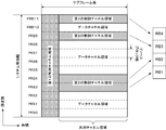
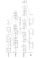
- FIG. 3 is a diagram illustrating an example of a subframe transmitted by the base station 100.
- one subframe having a system bandwidth composed of 12 physical resource block pairs (PRB; PhysicalPhysResource Block) is shown.
- the first zero or more OFDM symbols are the first control channel region.
- the number of OFDM symbols in the first control channel region is notified to the terminal.
- a dedicated notification region can be set for the first OFDM symbol, and notification can be dynamically made for each subframe.
- the first control channel region can be notified semi-statically using the control information of the upper layer.
- An area other than the first control channel area is a shared channel area.
- the shared channel region includes a data channel region and / or a second control channel region.
- PRB3, PRB4, PRB9, and PRB11 are the second control channel regions.
- the base station 100 notifies (sets) the second control channel region to the terminal 200 through higher layer control information.
- the control information for setting the second control channel region is control information set for each PRB or PRB group.
- PRB3, PRB4, PRB9, and PRB11 are set as the second control channel region.
- the second control channel region is assigned in units of a predetermined number of PRBs.
- the predetermined number of PRBs can be 4. In that case, the base station 100 sets a multiple of 4 PRBs in the terminal 200 as the second control channel region.
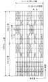
- FIG. 4 is a diagram illustrating an example of one resource block pair mapped by the base station 100.
- One resource block is composed of a predetermined frequency direction region and a predetermined time direction region, and one resource block pair is continuously arranged in the time direction.
- FIG. 4 shows two resource blocks (RB; Resource Block), and one resource block is composed of 12 subcarriers in the frequency direction and 7 OFDM symbols in the time direction. Each subcarrier in one OFDM symbol is called a resource element.
- Resource block pairs are arranged in the frequency direction, and the number of resource block pairs can be set for each base station. For example, the number of resource block pairs can be set to 6 to 110.
- the width in the frequency direction at that time is called a system bandwidth.
- the time direction of the resource block pair is called a subframe. Of each subframe, the seven OFDM symbols before and after in the time direction are also called slots.
- a resource block pair is also simply referred to as a resource block.
- R0 to R3 indicate cell-specific reference signals of antenna ports 0 to 3, respectively.
- the cell-specific reference signals of the antenna ports 0 to 3 are also referred to as CRS (Common Reference Signal).
- CRS Common Reference Signal
- the CRS shown in FIG. 4 is a case of four antenna ports, the number can be changed, for example, CRS of one antenna port or two antenna ports can be mapped.
- the cell-specific reference signals of the antenna ports 15 to 22 can be mapped as cell-specific reference signals different from the cell-specific reference signals of the antenna ports 0 to 3.
- the cell-specific reference signals of the antenna ports 15 to 22 are also referred to as transmission path condition measurement reference signals.
- C1 to C4 indicate transmission path condition measurement reference signals of CDM (Code Division Multiplexing) group 1 to CDM group 4, respectively.
- the channel state measurement reference signal is first mapped with an orthogonal code using a Walsh code, and then superimposed with a scramble code using a Gold code.
- the transmission path condition measurement reference signal is code-division multiplexed by orthogonal codes such as Walsh codes in the CDM group.
- the transmission path condition measurement reference signals are frequency division multiplexed (FDM) between CDM groups. Further, the transmission path condition measurement reference signal of the antenna ports 15 and 16 is mapped to C1, the transmission path condition measurement reference signal of the antenna ports 17 and 18 is mapped to C2, and the transmission path condition measurement of the antenna ports 19 and 20 is performed. The reference signal for mapping is mapped to C3, and the reference signal for transmission path condition measurement of the antenna ports 21 and 22 is mapped to C4. Also, the transmission path condition measurement reference signal can be set as reference signals corresponding to the eight antenna ports of the antenna ports 15 to 22. Also, the transmission path condition measurement reference signal can be set as reference signals corresponding to the four antenna ports of the antenna ports 15 to 18.
- FDM frequency division multiplexed
- the transmission path condition measurement reference signal can be set as reference signals corresponding to the two antenna ports of the antenna ports 15 to 16. Also, the transmission path condition measurement reference signal can be set as a reference signal corresponding to one antenna port of the antenna port 15. Further, the transmission path condition measurement reference signal can be mapped to some subframes, for example, can be mapped for each of a plurality of subframes. Further, the resource element for mapping the transmission path condition measurement reference signal may be different from the resource element shown in FIG. Further, a plurality of patterns may be defined in advance as the mapping pattern for the resource element of the transmission path condition measurement reference signal. Further, the base station 100 can set a plurality of transmission path condition measurement reference signals for the terminal 200.
- the transmission power of the reference signal for channel condition measurement can be further set, for example, the transmission power can be made zero.
- Base station 100 sets a reference signal for transmission path status measurement as terminal-specific control information for terminal 200 through RRC signaling. Based on the setting from base station 100, terminal 200 generates feedback information using a CRS and / or a transmission path condition measurement reference signal.
- D1 to D2 indicate terminal-specific reference signals of CDM (Code Division Multiplexing) group 1 to CDM group 2, respectively.
- the terminal-specific reference signal is first mapped with an orthogonal code using a Walsh code, and then a scramble code using a Gold code is superimposed.
- the terminal-specific reference signal is code division multiplexed by orthogonal codes such as Walsh codes in the CDM group.
- the terminal-specific reference signals are FDM between CDM groups.
- the terminal-specific reference signal can be mapped to a maximum of 8 ranks using 8 antenna ports (antenna ports 7 to 14) according to the control channel or data channel mapped to the resource block pair.
- the terminal-specific reference signal can change the CDM spreading code length and the number of mapped resource elements in accordance with the number of ranks to be mapped.
- the terminal-specific reference signal in the case where the rank number is 1 to 2 is configured by antenna code 7 to 8 with a spread code length of 2 chips and mapped to CDM group 1.
- the terminal-specific reference signal in the case where the number of ranks is 3 to 4 is configured by antenna chips 9 to 10 in addition to antenna ports 7 to 8 and having a spreading code length of 2 chips, and is further mapped to CDM group 2.
- the terminal-specific reference signals in the case where the number of ranks is 5 to 8 are configured as 4-port spreading code lengths as antenna ports 7 to 14 and are mapped to CDM group 1 and CDM group 2.
- the resource element filled in with white indicates an area (shared channel area) where the shared channel and / or the second control channel is arranged.
- the shared channel region is mapped to an OFDM symbol that is different from the rear OFDM symbol in the subframe, that is, the OFDM symbol in which the first control channel in the subframe is arranged, and a predetermined number of OFDM symbols are set for each subframe. can do.
- all or part of the shared channel region may be mapped to a predetermined OFDM symbol that is fixed regardless of the first control channel region in the subframe.
- the area where the shared channel is arranged can be set for each resource block pair.
- the second control channel region may be composed of all OFDM symbols regardless of the number of OFDM symbols in the first control channel region.
- the number of resource blocks can be changed according to the frequency bandwidth (system bandwidth) used by the communication system.
- the frequency bandwidth system bandwidth
- 6 to 110 resource blocks can be used, and the unit is also called a component carrier.
- the base station can set a plurality of component carriers for the terminal by frequency aggregation.
- one component carrier is configured with 20 MHz for a terminal, and five component carriers are set continuously and / or discontinuously in the frequency direction, so that a total communication system can use.
- the bandwidth can be 100 MHz.
- aggregation of a plurality of serving cells is supported in the downlink and uplink (referred to as carrier aggregation).
- a transmission bandwidth of up to 110 resource blocks can be used.
- one serving cell is defined as a primary cell (Pcell).
- a serving cell other than the primary cell is defined as a secondary cell (Scell; Secondary Cell).
- a carrier corresponding to a serving cell in the downlink is defined as a downlink component carrier (DLCC).
- a carrier corresponding to a primary cell in the downlink is defined as a downlink primary component carrier (DLPCC; Downlink Primary Component Carrier).
- DLPCC Downlink Primary Component Carrier
- a carrier corresponding to a secondary cell in the downlink is defined as a downlink secondary component carrier (DLSCC; Downlink Secondary Component Carrier).
- the carrier corresponding to the serving cell in the uplink is defined as an uplink component carrier (ULCC).
- ULCC uplink primary component carrier
- ULPCC uplink primary component carrier
- ULSCCC uplink secondary component carrier
- the primary base station can be regarded as a primary cell
- the secondary base station can be regarded as a secondary cell (the base station sets the terminal) (also referred to as HetNet deployment with a carrier aggregation).
- the PDCCH is composed of a plurality of control channel elements (CCEs).
- the number of CCEs used in each downlink component carrier is a downlink cell-specific reference according to the downlink component carrier bandwidth, the number of OFDM symbols constituting the PDCCH, and the number of transmission antennas of the base station 100 used for communication. Depends on the number of signal transmission antenna ports.
- the CCE is composed of a plurality of downlink resource elements (resources defined by one OFDM symbol and one subcarrier).
- a CCE used between the base station 100 and the terminal 200 is assigned a number for identifying the CCE.
- the CCE numbering is performed based on a predetermined rule.
- CCE_t indicates the CCE of CCE number t.
- the PDCCH is configured by a set of a plurality of CCEs (CCE aggregation).
- the number of CCEs constituting this set is referred to as a “CCE aggregation level” (CCE aggregation level).
- the CCE aggregation level constituting the PDCCH is set in the base station according to the coding rate set in the PDCCH and the number of bits of DCI included in the PDCCH. Note that combinations of CCE aggregation levels that may be used for terminals are determined in advance.
- a set of n CCEs is referred to as “CCE set level n”.
- One resource element group is composed of four downlink resource elements adjacent in the frequency domain. Furthermore, one CCE is constituted by 9 different resource element groups distributed in the frequency domain and the time domain. Specifically, for the entire downlink component carrier, all numbered resource element groups are interleaved in resource element group units using a block interleaver, and nine consecutive numbers after interleaving are performed. One CCE is configured by the resource element group.
- SS Search Space
- SS is composed of a plurality of CCEs.
- the SS is composed of a plurality of CCEs having consecutive numbers from the smallest CCE, and the number of CCEs having consecutive numbers is determined in advance.
- Each CCE aggregation level SS is composed of an aggregation of a plurality of PDCCH candidates.
- SSs are classified into CSS (Cell-specific SS) in which the number is common in the cell from the smallest CCE and USS (UE-specific SS) in which the number is unique to the terminal from the smallest CCE.
- CSS is assigned a PDCCH to which control information read by a plurality of terminals such as system information or information related to paging is assigned, or a downlink / uplink grant indicating an instruction of fallback or random access to a lower transmission method.
- PDCCH can be arranged.
- the base station transmits the PDCCH using one or more CCEs in the SS set in the terminal 200.
- Terminal 200 decodes the received signal using one or more CCEs in the SS and performs processing for detecting the PDCCH addressed to itself (referred to as blind decoding).
- the terminal 200 sets a different SS for each CCE aggregation level.
- terminal 200 performs blind decoding using a predetermined combination of CCEs in different SSs for each CCE aggregation level. In other words, terminal 200 performs blind decoding on each PDCCH candidate in a different SS for each CCE aggregation level. This series of processing in terminal 200 is called PDCCH monitoring.
- the second control channel (E-PDCCH, PDCCH on PDSCH, Enhanced PDCCH) is mapped to the second control channel region.
- the base station 100 sets monitoring of the second control channel for the terminal 200, and sets the second control channel region in the second control channel region.
- the control channel for terminal 200 is mapped. Further, when the base station 100 notifies the terminal 200 of the control channel through the first control channel region, the base station 100 notifies the terminal 200 of the first control channel regardless of the second control channel monitoring setting.
- a control channel for terminal 200 may be mapped to the control channel region. Further, when the base station 100 notifies the terminal 200 of the control channel through the first control channel region, the first control is performed when the base station 100 does not set the monitoring of the second control channel for the terminal 200.
- the control channel for terminal 200 may be mapped to the channel region.
- the terminal 200 when the monitoring of the second control channel is set by the base station 100, the terminal 200 is addressed to the control channel addressed to the terminal 200 in the first control channel area and / or addressed to the terminal 200 in the second control channel area. Blind decoding the control channel. In addition, when monitoring of the second control channel is not set by the base station 100, the terminal 200 does not blind-decode the control channel addressed to the terminal 200 in the first control channel.
- E-PDCCH control channel
- the base station 100 sets a second control channel region in the terminal 200.
- the number of RBs constituting the second control channel region is a multiple of a predetermined value.
- the number of RBs constituting the second control channel region is a multiple of four. That is, the second control channel region is set in units of RBs in which the number of RBs is a multiple of four.
- Base station 100 maps E-PDCCH for terminal 200 to the set second control channel region. Further, the base station 100 can also map E-PDCCH for a terminal different from the terminal 200. That is, a plurality of E-PDCCHs for a plurality of terminals can be multiplexed within the second control channel region.
- the E-PDCCH is composed of a plurality of enhanced control channel elements (E-CCE; Enhanced CCE).
- E-CCE is a unit constituting a control channel.
- the second control channel area is composed of a plurality of E-CCEs.
- the number of E-CCEs in the second control channel region is defined by a predetermined value.
- the number of E-CCEs in the second control channel region may be determined implicitly according to control information related to the second control channel set by the base station 100.
- the number of E-CCEs in the second control channel region may be determined by the number of PRBs in the second control channel region set by the base station 100.
- the number of E-CCEs in the second control channel region may be explicitly determined according to control information regarding the second control channel set by the base station 100.
- E-CCE is composed of multiple E-REG (Enhanced Resource Element Group).
- E-REG is used to define control channel mapping to resource elements.
- the E-REG is composed of a plurality of resource elements within one RB.
- the E-REG may be composed of a plurality of resource elements in a plurality of RBs.
- the E-REG may be configured with a plurality of resource elements in a plurality of RBs in the second control channel region.
- the E-REG may be configured by a plurality of resource elements in a plurality of RBs that configure the E-CCE.
- the number of E-REGs constituting one E-CCE is defined by a predetermined value.
- the number of E-REGs constituting one E-CCE may be determined implicitly by control information related to the second control channel set by the base station 100.
- the number of E-REGs constituting one E-CCE may be determined by a second control channel region mapping method (for example, distributed mapping or localized mapping) set by the base station 100.
- the number of E-REGs constituting one E-CCE is the mapping method of E-CCE and terminal-specific reference signal set by the base station 100 (mapping method of E-CCE and antenna port) May be determined by:
- the number of E-REGs constituting one E-CCE may be explicitly determined by control information regarding the second control channel set by the base station 100.
- multiple E-REGs constitute one RB.
- a plurality of mapping rules (mapping methods) between the E-REGs constituting the RB and the E-REGs constituting the E-CCE are defined.
- One of the mapping methods between the E-REG constituting the RB and the E-REG constituting the E-CCE is distributed mapping (distributed mapping rule).
- mapping is performed so as to be distributed to a plurality of the resource blocks.
- part or all of the E-REGs constituting the E-CCE are mapped to E-REGs in a plurality of RBs.
- part or all of the E-REGs constituting the RB are mapped from the E-REGs in a plurality of E-CCEs.
- one of the mapping methods between the E-REGs constituting the RB and the E-REGs constituting the E-CCE is localized mapping (local mapping rule).
- local mapping rule resources are mapped locally to resource blocks.
- all of the E-REGs constituting the E-CCE are mapped to the E-REGs in one RB.
- part or all of the E-REGs constituting the RB are mapped from all of the E-REGs in a plurality of RBs.
- the number of E-REGs constituting one RB is defined by a predetermined value.
- the number of E-REGs constituting one RB may be determined implicitly according to control information regarding the second control channel set by the base station 100.
- the number of E-REGs constituting one RB may be determined by a second control channel region mapping method (for example, distributed mapping or localized mapping) set by the base station 100.
- the number of E-REGs constituting one RB is determined by a mapping method between E-CCE and terminal-specific reference signal set by base station 100 (a mapping method between E-CCE and antenna port). May be.
- the number of E-REGs constituting one E-CCE may be explicitly determined by control information regarding the second control channel set by the base station 100.
- the method of mapping the E-PDCCH to the PRB by the base station 100 for the terminal 200 is as follows. First, E-PDCCH is mapped to one or more E-CCEs. Next, in the case of distributed mapping, a plurality of E-REGs constituting an E-CCE are mapped to E-REGs in a plurality of RBs. In the case of local mapping, a plurality of E-REGs constituting an E-CCE are mapped to E-REGs in one RB. Next, the plurality of RBs to which the E-REGs are mapped are mapped to some or all of the plurality of PRBs constituting the second control channel region.
- the mapping between the logical RB and the physical RB is performed according to a predetermined rule. For example, logical RB numbers and physical RB numbers are mapped in ascending order. For example, logical RBs are mapped so as to be distributed with respect to physical RBs.
- the E-CCE recognition method (that is, the viewpoint of mapping from the physical configuration to the logical configuration) for detecting the E-PDCCH notified from the base station 100 by the terminal 200 is as follows. is there. First, terminal 200 recognizes the PRB of the second control channel region set from base station 100 as an RB constituting the second control channel region. Next, terminal 200 recognizes E-REGs constituting the RBs in each of the RBs constituting the second control channel region. Next, in the case of distributed mapping, terminal 200 assumes that a plurality of E-REGs constituting an RB are mapped to E-REGs in a plurality of E-CCEs, and that E-REGs composed of a plurality of E-REGs. Recognize CCE. Furthermore, terminal 200 performs E-PDCCH detection processing (blind decoding) based on the recognized E-CCE. As a method for E-PDCCH detection processing, a method described later is used.
- E-PDCCH detection processing a method
- mapping method between RB and E-CCE constituting the second control channel region will be described using a specific example.
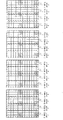
- FIG. 5 is a diagram illustrating an example in which E-REGs constituting one RB are distributedly mapped.
- the number of RBs in the second control channel region is four.
- the number of E-REGs constituting one E-CCE is four.
- the total number of E-REGs in the second control channel region is 64.
- the total number of E-CCEs in the second control channel region is 16.
- each E-REG constituting one E-CCE is mapped to an E-REG in a different RB. Specifically, E-REG1-1, E-REG1-2, E-REG1-3 and E-REG1-4 constituting E-CCE1 are mapped to RB1, RB2, RB3 and RB4, respectively.
- each E-REG constituting one RB is mapped from E-REGs in different E-CCEs.
- the 16 E-REGs that make up RB1 are the E-REG1-1, E-REG2-1, E-REG3-1, E-REG4-1, E that make up E-CCE1-16.
- FIG. 6 is a diagram illustrating an example in which E-REGs constituting one RB are locally mapped.
- the number of RBs in the second control channel region is four.
- the number of E-REGs constituting one E-CCE is four.
- the total number of E-REGs in the second control channel region is 64.
- the total number of E-CCEs in the second control channel region is 16.
- all of the E-REGs constituting one E-CCE are mapped to E-REGs in the same RB. Specifically, E-REG1-1, E-REG1-2, E-REG1-3, and E-REG1-4 constituting E-CCE1 are mapped to RB1.
- E-REGs constituting one RB are mapped from E-REGs constituting a plurality of E-CCEs.
- the 16 E-REGs that make up RB1 are the E-REG1-1, E-REG1-2, E-REG1-3, E-REG1-4, E that make up E-CCE1-4.
- -REG2-1, E-REG2-2, E-REG2-3, E-REG2-4, E-REG3-1, E-REG3-2, E-REG3-3, E-REG3-4, E-REG4 -1, E-REG4-2, E-REG4-3, E-REG4-4 are mapped.
- the E-REG used between the base station 100 and the terminal 200 is assigned a number for identifying the E-REG.
- E-REG numbering is performed based on a predetermined rule. Various methods can be used for the rules used for E-REG numbering.
- the numbered E-REG numbers are associated with the E-REGs constituting the RB described in FIGS.
- the E-REG numbers constituting one RB are commonly used in distributed mapping and local mapping.
- it is preferable that E-REG numbering is performed in consideration of each of distributed mapping and local mapping.
- E-REG numbering is performed so that E-CCE in local mapping is associated with an E-REG group to be described later.
- E-REG numbering rule for one RB will be described, but it can also be applied to E-REG numbering performed across a plurality of RBs.
- E-REG numbering examples are as follows. First, one RB is grouped for each predetermined number of resource elements. For example, one RB is grouped for each predetermined number of subcarriers. For example, one RB is grouped for every three subcarriers, and four groups are set. The group is also called an E-REG group. E-REG numbering is performed for each E-REG group. One E-REG group is composed of a plurality of E-REGs. In one E-REG group, E-REG numbering is a resource element having a small subcarrier number and a small OFDM symbol number (that is, a resource element of an OFDM symbol having a low frequency and an early time). ) Is started.
- the E-REG numbering is performed with priority in the time direction. Specifically, numbering is performed in the time direction in order from the resource element that is the start. When the resource element of the last OFDM symbol in the subframe is numbered, the subsequent E-REG number is numbered to the resource element of the first OFDM symbol of the subcarrier having a subcarrier number that is one higher. . With such rules, E-REG numbering is performed within the E-REG group. Similarly, the other E-REG groups are performed in the same manner.
- E-REG numbering resource elements to which terminal-specific reference signals, cell-specific reference signals, transmission path condition measurement reference signals and / or broadcast channels are mapped are numbered as they are (punctured). May be performed. That is, E-REG numbering is performed over the entire resource elements in the RB without depending on the signal mapped to the resource elements.
- Terminal 200 recognizes that a control channel is not mapped to a resource element to which a terminal-specific reference signal, a cell-specific reference signal, a transmission path condition measurement reference signal, and / or a broadcast channel are mapped. Thereby, since the definition of E-REG is determined without depending on the signal mapped to the resource element, the processing and storage capacity in the base station 100 and the terminal 200 can be reduced.
- E-REG numbering a resource element to which a cell-specific reference signal, a transmission path condition measurement reference signal, and / or a broadcast channel are mapped may be numbered as it is (punctured). . Also, E-REG numbering is performed considering only resource elements to which terminal-specific reference signals are mapped. For example, E-REG numbering is performed by skipping only resource elements to which terminal-specific reference signals are mapped (rate matching). That is, E-REG numbering is performed over the entire resource elements in the RB without depending on signals mapped to the resource elements, except for terminal-specific reference signals.
- Terminal 200 recognizes that a control channel is not mapped to a resource element to which a terminal-specific reference signal, a cell-specific reference signal, a transmission path condition measurement reference signal, and / or a broadcast channel are mapped. Thereby, since the definition of E-REG is determined without depending on the signal mapped to the resource element except for the terminal-specific reference signal, the processing and storage capacity in the base station 100 and the terminal 200 can be reduced. . Further, when the second control channel is demodulated using the terminal-specific reference signal, the terminal-specific reference signal is mapped to the RB to which the second control channel is mapped. Therefore, the second control channel can be mapped in consideration of resource overhead due to the terminal-specific reference signal.
- E-REG numbering resource elements to which terminal-specific reference signals, cell-specific reference signals, transmission path status measurement reference signals and / or broadcast channels are mapped are skipped (rate matching) and numbered. You may attach. That is, E-REG numbering is applied to all resource elements in the RB, except for resource elements to which terminal-specific reference signals, cell-specific reference signals, transmission path status measurement reference signals and / or broadcast channels are mapped. Done. Thereby, the second control channel can be mapped in consideration of the resource overhead due to the terminal-specific reference signal, the cell-specific reference signal, the transmission path condition measurement reference signal, and / or the broadcast channel.
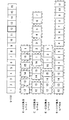
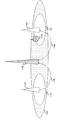
- FIG. 7 is a diagram illustrating an example of the configuration of E-REG in one RB.
- This figure shows the resource elements of one RB when the number of E-REGs constituting one RB is 16.
- Resource elements indicated by D1 and D2 indicate terminal-specific reference signals.
- E-REG is defined for resource elements other than the resource element to which the terminal-specific reference signal is mapped.
- Resource elements denoted by 1 to 16 indicate E-REGs, and each number indicates an E-REG number. That is, E-REG1 to E-REG16 are shown.
- E-REG1 is composed of nine resource elements.
- four E-REG groups are configured for every three subcarriers from the subcarriers having a low frequency.
- the E-REG group with the lowest frequency is composed of E-REG1 to E-REG4.
- the second lowest frequency E-REG group is composed of E-REG5 to E-REG8.
- the third lowest frequency E-REG group is composed of E-REG9 to E-REG12.
- the fourth lowest frequency E-REG group is composed of E-REG 13 to E-REG 16.
- E-REG shown in FIG. 7 is associated with the E-REG constituting the RB shown in FIGS.
- E-REG1 to E-REG16 shown in FIG. 7 are respectively E-REG1-1, E-REG2-1, E-REG3-1, E-REG4-1, E-REG5-1 shown in FIG. E-REG6-1, E-REG7-1, E-REG8-1, E-REG9-1, E-REG10-1, E-REG11-1, E-REG12-1, E-REG13-1, E- Corresponding to REG14-1, E-REG15-1, and E-REG16-1.
- the E-REGs constituting the RB shown in FIG. 5 are distributedly mapped, and the E-REGs constituting the RB shown in FIG. 6 are locally mapped. That is, the E-REGs constituting the RB can be commonly used without depending on the distributed mapping and the local mapping.
- the E-REGs constituting the E-CCE shown in FIG. 5 are associated with the E-REGs constituting the E-REG group in the RB in the local mapping. That is, in an RB composed of locally mapped E-REGs, the RB is composed of a plurality of E-CCEs. Further, the E-CCE is FDM mapped in the RB. Thereby, the mapping to the physical resource of the E-CCE in the local mapping can be performed locally by the distributed mapping and the local mapping without changing the configuration of the E-REG constituting the RB.
- the configuration of the E-REG in the RB shown in FIG. 7 can be further varied for each predetermined RB.
- the configuration of the E-REG in the RB can be set for some or all of the plurality of RBs configuring the second control channel region.
- the predetermined resource constituting the RB can be cyclically shifted for each RB in a part or all of the plurality of RBs constituting the second control channel region.
- the E-REG group constituting the RB can be cyclically shifted for each RB in a part or all of the plurality of RBs constituting the second control channel region.
- FIG. 8 is a diagram illustrating an example of the configuration of the E-REG set for each RB in the second control channel region.
- four E-REG groups constituting each RB are cyclically shifted in the frequency direction for every four RBs in the second control channel region.
- each E-REG group indicated by the same E-REG group number is composed of the same plurality of E-REGs.
- E-REG group 1 is composed of E-REGs 1 to 4.
- the number of E-REG groups in one RB may be the same as the number of RBs in the second control channel region or the number of RBs constituting the resources to which E-PDCCH is cyclically mapped. it can.
- the resource elements in each E-REG group are mapped to different resource elements in the RB for each RB that is cyclically shifted. Therefore, the total number of resource elements in each E-REG group mapped to four RBs is the same as the number of resource elements when mapped to one entire RB. That is, the overhead of a signal mapped for each RB, such as a terminal-specific reference signal, a cell-specific reference signal, a transmission path condition measurement reference signal, and / or a broadcast channel, can be the same between E-REG groups. .
- the present invention is not limited to this.
- the number of E-REGs in one RB is realized by a predetermined number.
- the present invention can be applied even when the number of E-REGs in one RB is 12.
- E-PDCCH The control channel (E-PDCCH) mapped to the second control channel region is processed for each control information for one or a plurality of terminals, and, similar to the data channel, scramble processing, modulation processing, layer mapping processing, Recording processing is performed. Moreover, the precoding process is performed on the control channel mapped to the second control channel region together with the terminal-specific reference signal.
- control channel mapped to the second control channel region is mapped including different control information in the front slot (first slot) and the rear slot (second slot) in the subframe. Can do. That is, the E-REG configuration shown in FIG. 7 may be set for each slot. For example, a control channel including allocation information (downlink allocation information) in a downlink shared channel that the base station 100 transmits to the terminal 200 is mapped to the forward slot in the subframe. In addition, a control channel including allocation information (uplink allocation information) in the uplink shared channel transmitted from terminal 200 to base station 100 is mapped to the rear slot in the subframe.
- a control channel including uplink allocation information for the base station 100 for the terminal 200 is mapped to the forward slot in the subframe, and downlink allocation information for the base station 100 to the base station 100 is mapped to the rear slot in the subframe. May be mapped.
- data channels for terminal 200 and / or other terminals may be mapped to the front and / or rear slots in the second control channel region.
- control channels for terminal 200 and / or other terminals may be mapped to the front and / or rear slots in the second control channel region.
- the terminal 200 has the second control channel region set by the base station 100 and recognizes a plurality of E-CCEs in the second control channel region.
- the SS is set by the base station 100 for the terminal 200.
- terminal 200 is set with an E-CCE number recognized as SS by base station 100.
- the terminal 200 is set with one E-CCE number serving as a start E-CCE number (reference E-CCE number) for the base station 100 to recognize as an SS.
- the terminal 200 recognizes an SS unique to the terminal 200 based on the start E-CCE number and a predetermined rule.
- the start E-CCE number is set by control information that is uniquely notified from base station 100 to terminal 200.
- the start E-CCE number may be determined based on an RNTI that is uniquely set from the base station 100 to the terminal 200.
- the start E-CCE number may be determined based on control information that is uniquely notified from base station 100 to terminal 200 and RNTI that is uniquely set from base station 100 to terminal 200.
- the start E-CCE number may be determined based on a subframe number numbered for each subframe or a slot number numbered for each slot. Thereby, the start E-CCE number is unique to terminal 200 and becomes unique information for each subframe or slot. Therefore, the SS of terminal 200 can be set differently for each subframe or slot.
- Various rules can be used for the rule for recognizing the SS from the start E-CCE number.
- the SS for searching for the second control channel in the terminal 200 can be composed of one or more E-CCEs. That is, it is composed of a set of one or more E-CCEs (E-CCE aggregation) with the E-CCE in the area set as the second control channel area as a unit. The number of E-CCEs constituting this set is referred to as an “E-CCE aggregation level” (E-CCE aggregation level).
- the SS is composed of a plurality of E-CCEs having consecutive numbers starting from the smallest E-CCE, and the number of one or more E-CCEs having consecutive numbers is predetermined.
- Each SS of each E-CCE aggregation level is configured by an aggregation of a plurality of second control channel candidates. Further, the number of candidates for the second control channel may be defined for each E-CCE aggregation level.
- SS may be set for each E-CCE aggregation level. For example, the start E-CCE for setting the SS may be set for each E-CCE aggregation level.
- the base station 100 transmits the second control channel using one or more E-CCEs in the E-CCE set in the terminal 200.
- Terminal 200 decodes the received signal using one or more E-CCEs in the SS, and performs processing for detecting the second control channel addressed to itself (blind decoding).
- terminal 200 sets a different SS for each E-CCE aggregation level.
- terminal 200 performs blind decoding using a predetermined combination of E-CCEs in different SSs for each E-CCE aggregation level.
- terminal 200 performs blind decoding on each second control channel candidate in a different SS for each E-CCE aggregation level (monitors E-PDCCH).
- FIG. 9 is a diagram illustrating an example of an SS for searching for a second control channel in the terminal 200.
- the number of E-CCEs in the second control channel region is 16.
- the start E-CCE number is E-CCE12.
- the SS shifts from the start E-CCE number in the direction in which the E-CCE number increases.
- the E-CCE number to be shifted next is the E-CCE number in the second control channel region. -The smallest E-CCE number among the CCEs.
- the m-th shifted E-CCE number is mod (X + m, N).
- mod (A, B) indicates a remainder obtained by dividing A by B. That is, the SS is set cyclically within the E-CCE in the second control channel region.
- the E-PDCCH candidates are shown in FIG. It becomes like this. For example, in the case of E-CCE aggregation level 4, the number of E-PDCCH candidates is two.
- the first E-PDCCH candidate is configured by E-CCE12, E-CCE13, E-CCE14, and E-CCE15.
- the second E-PDCCH candidate is configured by E-CCE16, E-CCE1, E-CCE2 and E-CCE3. Accordingly, as described with reference to FIGS. 5 and 6, the second control channel region is set in units of predetermined RBs, whereby the E-PDCCH can be mapped in the predetermined RBs. That is, resources for mapping the E-PDCCH can be set efficiently.
- FIG. 10 is a diagram illustrating an example of an SS for searching for a second control channel in the terminal 200. Differences from the SS example described in FIG. 9 are as follows.
- An E-CCE configured by one E-PDCCH is cyclically set within a predetermined E-CCE smaller than the E-CCE in the second control channel region.
- the resource for each of the four E-CCEs from the one with the smallest E-CCE number is set as a unit for mapping one E-PDCCH.
- the number of E-PDCCH candidates is six.
- each E-PDCCH candidate is set (defined) so as to be mapped to as many units as possible in a unit for mapping one E-PDCCH.
- the first E-PDCCH candidate is configured by E-CCE 12 and E-CCE 9.
- the second E-PDCCH candidate is configured by E-CCE 16 and E-CCE 13.
- the third E-PDCCH candidate is configured by E-CCE4 and E-CCE1.
- the fourth E-PDCCH candidate is configured by E-CCE8 and E-CCE5.
- the fifth E-PDCCH candidate is configured by E-CCE10 and E-CCE11.
- the sixth E-PDCCH candidate is configured by E-CCE14 and E-CCE15. Accordingly, as described with reference to FIGS.
- the second control channel region is set in units of predetermined RBs, whereby the E-PDCCH can be mapped in the predetermined RBs. That is, resources for mapping the E-PDCCH can be set efficiently. Also, in local mapping, when one RB is configured with a predetermined E-CCE, one E-PDCCH can be mapped to only one RB. Note that the E-PDCCH in the case of E-CCE aggregation level 8 is mapped to two RBs. Therefore, when terminal-specific precoding processing is performed on the E-PDCCH, a gain due to precoding processing can be efficiently obtained. Also, the terminal 200 can recognize a candidate for detecting such mapped E-PDCCH.
- the entire E-CCE obtained from the PRB set as the second control channel region is set as the SS setting range, but the present invention is not limited to this.
- the E-CCE obtained from a part of the PRB set as the second control channel region may be a range for setting the SS. That is, the PRB or E-CCE set as the second control channel region may be different from the PRB or E-CCE set as the SS. Even in that case, it is preferable that the PRB set as the SS has a predetermined multiple as a unit.
- the E-CCE set as SS is RB5 to RB8. And E-CCE obtained from RB13 to RB16.
- the resource set as SS may be an E-CCE with a multiple of a predetermined number as a unit.
- E-CCE aggregation levels are 1, 2, 4, and 8 have been described, the present invention is not limited to this.
- Other E-CCE aggregation levels may be used to change the predetermined reception quality of E-PDCCH or the overhead due to E-PDCCH.
- E-PDCCH E-CCE, E-REG
- a rule defined in advance is used for associating the E-PDCCH with the antenna port of the terminal-specific reference signal.
- a plurality of association rules can be defined. When a plurality of associations between the E-PDCCH and the antenna port of the terminal-specific reference signal are defined, information indicating either one is explicitly or implicitly notified from the plurality of association rules.
- the notification method can be set by notifying information indicating any one of the plurality of association rules by RRC signaling.
- the terminal 200 can identify one of the plurality of association rules. For example, one of a plurality of association rules may be notified indirectly from information indicating distributed mapping or local mapping notified by RRC signaling. Information indicating any one of a plurality of association rules may be set for each terminal. Information indicating any one of a plurality of association rules may be set for each second control channel region to be set. Therefore, when a plurality of second control channel regions are set, terminal 200 may set any one of a plurality of association rules independently.
- An example of a rule for associating an E-PDCCH with an antenna port of a terminal-specific reference signal is a terminal-specific precoding antenna port rule.
- the terminal-specific precoding antenna port rule precoding processing specific to the terminal transmitting the E-PDCCH can be performed.
- One RB is divided into a predetermined number of resources.
- the divided resources are associated with different antenna ports of terminal-specific reference signals. For example, one RB is divided into four resources.
- the four divided resources are associated with antenna ports 7 to 10, respectively.
- each divided resource (divided resource) can be associated with E-CCE in local mapping. That is, each E-CCE in the local mapping is associated with a different antenna port.
- each E-PDCCH can be transmitted using any of the antenna ports associated with the divided resources to be mapped.
- Terminal 200 determines an antenna port of a terminal-specific reference signal for demodulation processing according to resources in E-PDCCH candidates for blind decoding. Also, terminal 200 may be notified from base station 100 of an antenna port of a terminal-specific reference signal for an E-PDCCH candidate for blind decoding.
- the terminal-specific precoding antenna port rule is preferably used when performing the local mapping described with reference to FIG. Note that the terminal-specific precoding antenna port rule may also be used when the distributed mapping described in FIG. 5 is performed.
- Another example of the rule for associating the E-PDCCH with the antenna port of the terminal-specific reference signal is a shared antenna port rule.
- a plurality of E-PDCCHs share an antenna port of a predetermined terminal-specific reference signal.
- each terminal performs E-PDCCH demodulation processing using an antenna port of a predetermined terminal-specific reference signal.
- the terminal-specific reference signal of the antenna port is transmitted between a plurality of terminals. Shared by. For example, in the second control channel region in which the shared antenna port rule is used, terminal-specific reference signals for antenna ports 7 and 9 are set for E-PDCCH demodulation processing.
- E-PDCCH mapped to the second control channel region in which the shared antenna port rule is used performs transmission diversity such as SFBC using the two antenna ports 7 and 9.
- antenna ports 7 and 9 are reference signals mapped to different resource elements, respectively, and therefore, twice as compared with the case of transmitting a signal through one antenna port. Electricity will be used. Therefore, terminal 200 can perform highly accurate propagation path estimation.
- the shared antenna port rule is preferably used when the distributed mapping described in FIG. 5 is performed. Note that the common antenna port rule may also be used when performing the local mapping described with reference to FIG.
- the mapping method between the RB and the E-CCE constituting the second control channel region has been described by the distributed mapping and the local mapping.
- the mapping method between the RB and the E-CCE constituting the second control channel region may be defined by a rule for associating the E-PDCCH with the antenna port of the terminal-specific reference signal.
- a mapping method between RBs and E-CCEs constituting the second control channel region may be defined by terminal-specific precoding antenna port rules and shared antenna port rules.
- the distributed mapping in the above description may be a mapping when a shared antenna port rule is used.
- the local mapping in the above description may be a mapping when the terminal-specific precoding antenna port rule is used.
- the second control channel setting method (second control channel region setting method / second control channel monitoring setting method) for the base station 100 to the terminal 200 will be described.
- the setting of the second control channel region and the setting of the transmission mode implicitly indicate the setting of monitoring of the second control channel.
- the base station 100 sets the second control channel by notifying the terminal 200 of terminal-specific setting information (RadioResourceConfigDedicated) for the radio resource through higher layer control information (RRC signaling).
- the terminal-specific setting information for radio resources is control information used for setting / changing / releasing resource blocks, terminal-specific settings for physical channels, and the like.
- the base station 100 notifies the terminal 200 of terminal-specific setting information for the radio resource.
- Terminal 200 performs terminal-specific settings for radio resources based on terminal-specific setting information for radio resources from base station 100, and notifies base station 100 of the completion of setting of terminal-specific setting information for radio resources.
- the terminal-specific setting information for the radio resource includes terminal-specific setting information (PhysicalConfigDedicated) for the physical channel.
- the terminal-specific setting information for the physical channel is control information that defines terminal-specific settings for the physical channel.
- the terminal-specific setting information for the physical channel includes transmission path status report setting information (CQI-ReportConfig), terminal information for antenna information (AntennaInfoDedicated), and terminal-specific setting information for the second control channel (EPDCCH-ConfigDedicated). Consists of.
- the setting information of the transmission path status report is used to define setting information for reporting the transmission path status in the downlink.
- the terminal-specific setting information in the antenna information is used to define terminal-specific antenna information in the base station 100.
- the terminal-specific setting information for the second control channel is used to define terminal-specific setting information for the second control channel. Further, since the terminal-specific setting information of the second control channel is notified and set as control information specific to terminal 200, the second control channel area to be set is set as an area specific to terminal 200.
- the transmission path status report setting information includes aperiodic transmission path status report setting information (cqi-ReportModeAperiodic) and periodic transmission path status report setting information (CQI-ReportPeriodic).
- the setting information of the aperiodic transmission path status report is setting information for aperiodically reporting the transmission path status in the downlink 103 through an uplink shared channel (PUSCH; Physical Uplink Shared Channel).
- the setting information of the periodic transmission path status report is setting information for periodically reporting the transmission path status in the downlink through an uplink control channel (PUCCH; Physical Uplink Control Channel).
- the terminal-specific setting information of the antenna information includes a transmission mode (transmission Mode).
- the transmission mode is information indicating a transmission method in which the base station 100 communicates with the terminal 200.
- the transmission mode is defined in advance as transmission modes 1 to 10.
- Transmission mode 1 is a transmission mode using a single antenna port transmission method using antenna port 0.
- Transmission mode 2 is a transmission mode using a transmission diversity method.
- Transmission mode 3 is a transmission mode that uses a cyclic delay diversity scheme.
- Transmission mode 4 is a transmission mode that uses a closed-loop spatial multiplexing scheme.
- Transmission mode 5 is a transmission mode that uses a multi-user MIMO scheme.
- Transmission mode 6 is a transmission mode that uses a closed-loop spatial multiplexing scheme that uses a single antenna port.
- the transmission mode 7 is a transmission mode using a single antenna port transmission method using the antenna port 5.
- Transmission mode 8 is a transmission mode that uses a closed-loop spatial multiplexing scheme that uses antenna ports 7 to 8.
- Transmission mode 9 is a transmission mode that uses a closed-loop spatial multiplexing scheme that uses antenna ports 7 to 14. Transmission modes 1 to 9 are also referred to as a first transmission mode.
- the transmission mode 10 is defined as a transmission mode different from the transmission modes 1 to 9.
- the transmission mode 10 can be a transmission mode using a CoMP scheme.
- the expansion due to the introduction of the CoMP method includes optimization of the transmission path status report and improvement of accuracy (for example, introduction of precoding information suitable for CoMP communication, phase difference information between base stations, etc.) and the like.
- the transmission mode 10 can be a transmission mode that uses a communication method that is an extension (advanced) of the multi-user MIMO method that can be realized by the communication methods shown in the transmission modes 1 to 9.
- the transmission mode 10 can be a transmission mode in which the second control channel region can be set. Further, the transmission mode 10 can be a transmission mode using a CoMP scheme and / or an extended multi-user MIMO scheme in addition to all or part of the communication schemes shown in the transmission modes 1 to 9. For example, the transmission mode 10 can be a transmission mode that uses a CoMP scheme and / or an extended multi-user MIMO scheme in addition to the communication scheme shown in the transmission mode 9. In addition, the transmission mode 10 can be a transmission mode in which a plurality of transmission path condition measurement reference signals (CSI-RS; Channel State Information-RS) can be set.
- CSI-RS transmission path condition measurement reference signals
- Channel State Information-RS Channel State Information-RS
- the base station 100 does not notify the terminal set to the transmission mode 10 that can use a plurality of transmission schemes that one of the plurality of transmission schemes is used when transmitting the data channel. Can also communicate. That is, even if the terminal 200 is set to the transmission mode 10 that can use a plurality of transmission schemes, the terminal 200 can communicate without receiving any notification of using one of the plurality of transmission schemes when receiving a data channel. it can.
- the second transmission mode is a transmission mode in which the second control channel can be set. That is, when the base station 100 sets the terminal 200 to the first transmission mode, the base station 100 maps the control channel for the terminal 200 to the first control channel region. Further, when the base station 100 is set to the second transmission mode for the terminal 200, the base station 100 maps the control channel for the terminal 200 to the first control channel region and / or the second control channel region. On the other hand, when the base station 100 sets the first transmission mode, the terminal 200 performs blind decoding on the first control channel. Furthermore, when the base station 100 sets the second transmission mode, the terminal 200 performs blind decoding on the first control channel and / or the second control channel.
- terminal 200 sets a control channel for blind decoding based on whether or not terminal-specific setting information of the second control channel is set by base station 100 regardless of the transmission mode. That is, when the terminal-specific setting information of the second control channel is not set for terminal 200, base station 100 maps the control channel for terminal 200 to the first control channel region. Further, when the terminal-specific setting information of the second control channel is set for terminal 200, base station 100 sets the control channel for terminal 200 to the first control channel region and / or the second control channel region. Map. On the other hand, when the terminal-specific setting information of the second control channel is set by the base station 100, the terminal 200 performs blind decoding on the first control channel and / or the second control channel. In addition, when the terminal-specific setting information of the second control channel is not set by the base station 100, the terminal 200 performs blind decoding on the first control channel.
- the terminal-specific setting information of the second control channel includes subframe setting information (EPDCCH-SubframeConfig-r11) of the second control channel.
- the subframe setting information of the second control channel is used for defining subframe information for setting the second control channel.
- the second control channel subframe setting information includes a subframe setting pattern (subframeConfigPattern-r11) and second control channel setting information (epdcch-Config-r11).
- the subframe setting pattern is information indicating a subframe for setting the second control channel.
- the subframe setting pattern is n-bit bitmap format information. The information shown in each bit indicates whether or not the subframe is set as the second control channel. That is, the subframe setting pattern can set n subframes as a cycle. At that time, a predetermined subframe to which a synchronization signal, a broadcast channel, and the like are mapped can be excluded. Specifically, the remainder obtained by dividing the subframe number defined for each subframe by n corresponds to each bit of the subframe setting pattern. For example, n is defined in advance as a value such as 8 or 40.
- the subframe When the information for a subframe having a subframe setting pattern is “1”, the subframe is set as the second control channel. When information on a subframe having a subframe setting pattern is “0”, the subframe is not set as the second control channel.
- a predetermined subframe to which a synchronization signal for the terminal 200 to synchronize with the base station 100, a broadcast channel for broadcasting the control information of the base station 100, and the like is mapped is not set as a second control channel in advance. can do.
- the subframe pattern set as the second control channel is indexed in advance, and information indicating the index is defined as the subframe setting pattern.
- the terminal-specific setting information of the second control channel includes a resource allocation type (resourceAllocationType-r11) and resource allocation information (resourceBlockAssignment-r11).
- the resource allocation type is information indicating a format (type) of information for designating a resource block to be set as the second control channel region in the subframe.
- the resource allocation information is information for designating a resource block to be set as the second control channel, and is defined based on the resource allocation type format. When the resource allocation method is fixed in advance, the resource allocation type need not be notified.
- the resource allocation information can use a bitmap format that designates a resource block to be set as the second control channel region for each PRB. This resource allocation information indicates whether each bit in the bitmap is associated with one RPB and that PRB is set as the second control channel region. For example, when the system bandwidth is composed of N_RB RBs, the information amount of the resource allocation information is N_RB bits. Further, for example, the resource allocation information may be information indicating the number of a resource block set as the second control channel region.
- the resource allocation type can specify a plurality of resource allocation information as types 0-2.
- the resource allocation information is control information for allocating to a VRB (Virtual Resource Block).
- the resource allocation information is information in a bitmap format that can be allocated for each resource block group defined in units of a plurality of consecutive VRBs. Note that the number of VRBs in the resource block group can be defined according to the system bandwidth.
- the resource allocation type is type 1
- the resource allocation information is allocated for each VRB in the plurality of resource block group subsets in the resource block group subset in which each VRB in the resource block group is defined as one of the plurality of subsets. Bitmap format information that can be.
- the resource allocation information also includes information indicating the selected resource block group subset.
- the resource allocation information is information indicating the VRB that is the start of allocation and information indicating the number of VRBs to be allocated in consecutive VRBs. Further, the resource allocation information can be in a bitmap format in which one bit corresponds to one VRB.
- the number of VRBs is the same as the number of PRBs.
- a plurality of types of VRB are defined. These types define VRB to PRB mapping (PRB mapping).
- PRB mapping VRB to PRB mapping
- the VRB number (VRB position) and the PRB number (PRB number) are mapped to be the same.
- the PRB numbers are assigned in order from the PRB having the lowest frequency.
- the VRB numbers are defined in advance and mapped by a method so that the VRB numbers are distributed (random) with respect to the PRB numbers.
- hopping can be further performed between slots, and the second slot of each VRB can be hopped to a different VRB. Whether or not to hop the second slot may be notified by RRC signaling or PDCCH signaling and switched, or may be defined in advance.
- RRC signaling or PDCCH signaling and switched or may be defined in advance.
- the PRB mapping is only the localized type.
- the PRB mapping is a localized type or a distributed type.
- the resource allocation type included in the setting information of the second control channel also includes control information (PRB mapping information) for PRB mapping.
- the resource allocation type can be control information indicating any of type 0, type 1, type 2 localized, and type 2 distributed.
- the terminal-specific setting information of the second control channel is configured to include information indicating a mapping method between logical resources and physical resources in the second control channel region. For example, information indicating either the distributed mapping method or the local mapping method shown in FIGS. 5 and 6 is included.
- the terminal-specific setting information of the second control channel includes information indicating correspondence between resources (E-REG, E-CCE, or E-PDCCH) constituting the RB and the antenna port of the terminal-specific reference signal. Consists of including.
- the information indicating the association between the resource and the antenna port of the terminal-specific reference signal indicates that the antenna port of the terminal-specific reference signal for demodulating the resource configuring the RB is shared in the RB. .
- the information indicating the correspondence between the resource and the antenna port of the terminal-specific reference signal indicates that a different terminal port of the terminal-specific reference signal is used for each resource constituting the RB.
- the terminal-specific setting information of the second control channel may include information indicating the antenna port of the terminal-specific reference signal corresponding to the resource (E-REG, E-CCE, or E-PDCCH) constituting the RB. . Further, the terminal-specific setting information of the second control channel is
- the base station 100 when setting the second control channel for the terminal 200, the base station 100 includes the terminal-specific setting information of the second control channel in the terminal-specific setting information for the radio resource by RRC signaling. To notify. Further, when the base station 100 changes the second control channel set for the terminal 200, the radio resource including the terminal-specific setting information of the second control channel whose parameter has been changed similarly by RRC signaling. Notify terminal-specific setting information for. Further, when releasing (releasing) the set second control channel, the base station 100 similarly notifies the terminal 200 by RRC signaling. For example, the terminal specific setting information for the radio resource not including the terminal specific setting information of the second control channel is notified. Also, control information for releasing the terminal-specific setting information of the second control channel may be notified.
- resource elements and resource blocks are used as data channel, control channel, PDSCH, PDCCH and reference signal mapping units, and subframes and radio frames are used as time direction transmission units. This is not a limitation. The same effect can be obtained even if a region and a time unit composed of an arbitrary frequency and time are used instead.
- the extended physical downlink control channel 103 arranged in the PDSCH region is referred to as E-PDCCH, and the distinction from the conventional physical downlink control channel (PDCCH) has been clearly described.
- PDCCH physical downlink control channel
- the extended physical downlink control channel arranged in the PDSCH region and the conventional physical downlink control channel arranged in the PDCCH region perform different operations, the E-PDCCH And PDCCH are substantially the same as the embodiments described above.
- the base station can determine whether or not the functions described in the above embodiments can be used. More specifically, when the function described in each of the above embodiments can be used, information indicating it is included in the terminal capability information, and when the function described in each of the above embodiments is not usable, Information related to this function may not be included in the terminal capability information. Alternatively, when the function described in each of the above embodiments can be used, 1 is set in the predetermined bit field of the function group information, and when the function described in each of the above embodiments is not usable, the function group information The predetermined bit field may be set to 0.
- resource elements and resource blocks are used as data channel, control channel, PDSCH, PDCCH and reference signal mapping units, and subframes and radio frames are used as time direction transmission units.
- the case of demodulating using a precoded RS is described, and the port corresponding to the precoded RS is described using a port equivalent to the MIMO layer.
- the same effect can be obtained by applying the present invention to ports corresponding to different reference signals.
- Unprecoded RS is used instead of Precoded RS, and a port equivalent to an output end after precoding processing or a port equivalent to a physical antenna (or a combination of physical antennas) can be used as a port.
- the program that operates in the base station 100 and the terminal 200 related to the present invention is a program (a program that causes a computer to function) that controls the CPU and the like so as to realize the functions of the above-described embodiments related to the present invention.
- Information handled by these devices is temporarily stored in the RAM at the time of processing, then stored in various ROMs and HDDs, read out by the CPU, and corrected and written as necessary.
- a recording medium for storing the program a semiconductor medium (for example, ROM, nonvolatile memory card, etc.), an optical recording medium (for example, DVD, MO, MD, CD, BD, etc.), a magnetic recording medium (for example, magnetic tape, Any of a flexible disk etc. may be sufficient.
- the processing is performed in cooperation with the operating system or other application programs.
- the function of the invention may be realized.
- the program when distributing to the market, can be stored in a portable recording medium for distribution, or transferred to a server computer connected via a network such as the Internet.
- the storage device of the server computer is also included in the present invention.
- part or all of the base station 100 and the terminal 200 in the above-described embodiment may be realized as an LSI that is typically an integrated circuit. Each functional block of base station 100 and terminal 200 may be individually chipped, or a part or all of them may be integrated into a chip.
- the method of circuit integration is not limited to LSI, and may be realized by a dedicated circuit or a general-purpose processor.
- an integrated circuit based on the technology can also be used.
- a base station is a base station that communicates with a terminal using a resource block configured with a predetermined time domain and a predetermined frequency domain, and is a reference signal unique to the terminal.
- a terminal-specific control channel generating unit that generates a terminal-specific control channel that is transmitted by mapping to a terminal-specific control channel region configured by a predetermined number of the resource blocks using the same antenna port as the terminal-specific reference signal;
- the resource block in the terminal-specific control channel region is divided into a plurality of resource element groups, and the terminal-specific control channel is mapped so as to be distributed to the plurality of resource blocks, or the resource Using local mapping rules that map locally to the block It is mapped to resource element groups.
- a base station is the base station described above, and the resource element group is common to the distributed mapping rule and the local mapping rule.
- a base station is the above-described base station, wherein the resource block in the terminal-specific control channel region stores information indicating either the distributed mapping rule or the local mapping rule. Set every time.
- a terminal is a terminal that communicates with a base station using a resource block configured with a predetermined time domain and a predetermined frequency domain, and the base station is unique to the terminal.
- a control channel processing unit that receives and transmits a terminal-specific control channel that is mapped and transmitted to a terminal-specific control channel region configured by a predetermined number of the resource blocks using the same antenna port as a terminal-specific reference signal that is a reference signal;
- a channel estimation unit that performs channel estimation for demodulating the terminal-specific control channel using the terminal-specific reference signal, and the resource block in the terminal-specific control channel region includes a plurality of resources It is divided into element groups, and the terminal-specific control channel is mapped so as to be distributed among the resource blocks. Grayed is the distributed mapping rule or, using the local mapping rules to be locally mapped to the resource block is mapped to the resource element groups.
- a communication system is a communication system in which a base station and a terminal communicate with each other using a resource block configured with a predetermined time domain and a predetermined frequency domain
- the base station includes: Using the same antenna port as a terminal-specific reference signal that is a reference signal specific to the terminal, a terminal-specific control channel that is transmitted by being mapped to a terminal-specific control channel region configured by a predetermined number of the resource blocks is generated A terminal-specific control channel generation unit, and the terminal uses a control channel processing unit that receives the terminal-specific control channel and a channel estimation for demodulating the terminal-specific control channel using the terminal-specific reference signal A channel estimation unit that performs the resource estimation in the terminal-specific control channel region.
- a distributed mapping rule that is mapped to be distributed to a plurality of resource blocks, or a local mapping rule that is mapped locally to the resource block, It is mapped to the resource element group.
- a communication method is a communication method of a base station that communicates with a terminal using a resource block configured with a predetermined time domain and a predetermined frequency domain, and is a reference unique to the terminal.
- a terminal-specific reference signal that is a signal
- the resource block in the terminal-specific control channel region is divided into a plurality of resource element groups, and the terminal-specific control channel is mapped to be distributed so as to be distributed to the plurality of resource blocks, or the resource block Using a local mapping rule that maps locally to It is mapped to an element group.
- a communication method is a communication method of a terminal that communicates with a base station using a resource block configured with a predetermined time domain and a predetermined frequency domain, wherein the base station A step of receiving a terminal-specific control channel that is transmitted by being mapped to a terminal-specific control channel region configured by a predetermined number of the resource blocks using the same antenna port as a terminal-specific reference signal that is a terminal-specific reference signal And performing a channel estimation for demodulating the terminal-specific control channel using the terminal-specific reference signal, and the resource block in the terminal-specific control channel region includes a plurality of resource elements It is divided into groups, and the terminal-specific control channel is mapped so as to be distributed among the resource blocks.
- Distributed mapping rule is or, by using the local mapping rules to be locally mapped to the resource block is mapped to the resource element groups.
- a communication method is a communication method for a communication system in which a base station and a terminal communicate with each other using a resource block configured with a predetermined time domain and a predetermined frequency domain.
- the station uses the same antenna port as the terminal-specific reference signal that is a reference signal specific to the terminal, and transmits the terminal-specific control channel that is mapped and transmitted to the terminal-specific control channel region configured by a predetermined number of the resource blocks
- the terminal receives the terminal-specific control channel, and uses the terminal-specific reference signal to perform propagation path estimation for demodulating the terminal-specific control channel;
- the resource block in the terminal-specific control channel region is divided into a plurality of resource element groups, A terminal-specific control channel is mapped to the resource element group using a distributed mapping rule that is mapped to be distributed to a plurality of the resource blocks or a local mapping rule that is mapped locally to the resource block.
- An integrated circuit is an integrated circuit realized in a base station that communicates with a terminal using a resource block configured with a predetermined time domain and a predetermined frequency domain.
- the terminal-specific reference signal which is a specific reference signal
- the function to generate a terminal-specific control channel that is transmitted by being mapped to a terminal-specific control channel region composed of a predetermined number of the resource blocks is realized.
- the resource block in the terminal-specific control channel region is divided into a plurality of resource element groups, and the terminal-specific control channel is mapped so as to be distributed to the plurality of resource blocks, or Using local mapping rules that map locally to resource blocks, It is mapped to the source element group.
- An integrated circuit is an integrated circuit of a terminal that communicates with a base station using a resource block configured with a predetermined time domain and a predetermined frequency domain, and the base station A function for receiving a terminal-specific control channel, which is transmitted by mapping to a terminal-specific control channel region composed of a predetermined number of the resource blocks using the same antenna port as a terminal-specific reference signal that is a terminal-specific reference signal And a function of performing channel estimation for demodulating the terminal-specific control channel using the terminal-specific reference signal, and the resource block in the terminal-specific control channel region includes a plurality of resource elements Divided into groups, the terminal-specific control channel is mapped to be distributed among the resource blocks. Distributed mapping rule or, using the local mapping rules to be locally mapped to the resource block is mapped to the resource element groups.
- the present invention is suitable for use in a radio base station apparatus, a radio terminal apparatus, a radio communication system, and a radio communication method.
- Base station 101 206 Upper layer 102 Data channel generation unit 103 Second control channel generation unit 104 Terminal specific reference signal multiplexing unit 105 Precoding unit 106 First control channel generation unit 107 Cell specific reference signal multiplexing unit 108 Transmission signal Generation unit 109 Transmission unit 200, 1104 Terminal 201 Reception unit 202 Received signal processing unit 203 Propagation path estimation unit 204 Control channel processing unit 205 Data channel processing units 801 to 804 Control channel 1101 Macro base station 1102, 1103 RRH 1108, 1109 Line 1105, 1106, 1107 Coverage
Abstract
The objective of the invention is to allow a base station to efficiently notify terminals of the information of control for the terminals in a wireless communication system in which the base station and the terminals communicate with each other. A base station, which communicates with terminals by use of resource blocks constituted in predetermined time and frequency domains, comprises a terminal-specific control channel generating unit that generates, by use of the same antenna port as terminal-specific reference signals that are reference signals specific to respective terminals, terminal-specific control channels to be mapped onto a terminal-specific control channel domain, which is constituted by a predetermined number of resource blocks, for transmission. The resource blocks in the terminal-specific control channel domain are divided into a plurality of resource element groups. The terminal-specific control channels are mapped onto the resource element groups by use of a distribution mapping rule according to which the terminal-specific control channels are mapped in such a manner that the terminal-specific control channels are distributed to a plurality of resource blocks or by use of a local mapping rule according to which the terminal-specific control channels are locally mapped onto the resource blocks.
Description
本発明は、基地局、端末、通信システム、通信方法および集積回路に関する。
The present invention relates to a base station, a terminal, a communication system, a communication method, and an integrated circuit.
3GPP(Third Generation Partnership Project)によるWCDMA(Wideband Code Division Multiple Access)、LTE(Long Term Evolution)、LTE-A(LTE-Advanced)やIEEE(The Institute of Electrical and Electronics engineers)によるWireless LAN、WiMAX(Worldwide Interoperability for Microwave Access)のような無線通信システムでは、基地局(セル、送信局、送信装置、eNodeB)および端末(移動端末、受信局、移動局、受信装置、UE(User Equipment))は、複数の送受信アンテナをそれぞれ備え、MIMO(Multi Input Multi Output)技術を用いることにより、データ信号を空間多重し、高速なデータ通信を実現する。
WirelessMA LAN (wideXLAN, wideband) by WCDMA (Wideband Code Division Multiple Access) by 3GPP (Third Generation Partnership Project), LTE (Long Term Evolution), LTE-A (LTE-Advanced) and IEEE (The Institute of Electrical Electronics and Electronics Electronics engineers) In a wireless communication system such as Interoperability (for Microwave Access), there are a plurality of base stations (cells, transmitting stations, transmitting devices, eNodeBs) and terminals (mobile terminals, receiving stations, mobile stations, receiving devices, UEs (User Equipment)). The transmission / reception antennas are respectively provided, and by using MIMO (Multi-Input-Multi-Output) technology, data signals are spatially multiplexed to realize high-speed data communication.
このような無線通信システムにおいて、基地局は、端末に対して下りリンクデータ(下りリンク共用チャネル(DL-SCH;Downlink Shared Channel)に対するトランスポートブロック)を送信する場合、基地局と端末との間において既知の信号である復調用参照信号(DMRS;Demodulation Reference Signalsとも呼称される)を多重して送信する。ここで、復調用参照信号は、ユーザー装置スペシフィック参照信号(UE-specific RS、端末固有(特有)のRS)とも呼称される。以下、復調用参照信号を、単に、参照信号とも記載する。
In such a wireless communication system, when a base station transmits downlink data (a transport block for a downlink shared channel (DL-SCH)) to a terminal, the base station is connected between the base station and the terminal. 2 multiplexes and transmits a demodulation reference signal (also referred to as DMRS; also referred to as Demodulation Reference Signals). Here, the demodulation reference signal is also referred to as a user equipment specific reference signal (UE-specific RS, terminal-specific (specific) RS). Hereinafter, the demodulation reference signal is also simply referred to as a reference signal.
例えば、参照信号は、プレコーディング処理が適用される前に、下りリンクデータと多重される。そのため、端末は、参照信号を用いることによって、適用されたプレコーディング処理および伝送路状態を含めた等化チャネルを測定することができる。すなわち、端末は、基地局によって適用されたプレコーディング処理を通知されなくても、下りリンクデータを復調することができる。
For example, the reference signal is multiplexed with the downlink data before the precoding process is applied. Therefore, the terminal can measure the equalization channel including the applied precoding process and transmission path state by using the reference signal. That is, the terminal can demodulate the downlink data without being notified of the precoding process applied by the base station.
ここで、下りリンクデータは、物理下りリンク共用チャネル(PDSCH;Physical Downlink Shared Channel)にマップされる。すなわち、参照信号は、PDSCHの復調に使用される。また、例えば、参照信号は、対応するPDSCHがマップされるリソースブロック(物理リソースブロック、リソースとも呼称される)でのみ送信される。
Here, the downlink data is mapped to a physical downlink shared channel (PDSCH; Physical Downlink Shared Channel). That is, the reference signal is used for demodulation of PDSCH. Further, for example, the reference signal is transmitted only in a resource block (also referred to as a physical resource block or a resource) to which the corresponding PDSCH is mapped.
ここで、カバレッジの広いマクロ基地局と、そのマクロ基地局よりもカバレッジの狭いRRH(Remote Radio Head)などによるヘテロジーニアスネットワーク配置(HetNet;Heterogeneous Network deployment)を用いた無線通信システムが検討されている。図11は、ヘテロジーニアスネットワーク配置を用いた無線通信システムの概要図である。図11に示すように、例えば、ヘテロジーニアスネットワークは、マクロ基地局1101、RRH1102、RRH1103によって構成される。
Here, a wireless communication system using a heterogeneous network arrangement (HetNet; Heterogeneous Network deployment) such as a macro base station with a wide coverage and an RRH (Remote Radio Head) with a narrower coverage than the macro base station is being studied. . FIG. 11 is a schematic diagram of a wireless communication system using a heterogeneous network arrangement. As shown in FIG. 11, for example, the heterogeneous network includes macro base stations 1101, RRH 1102, and RRH 1103.
図11において、マクロ基地局1101はカバレッジ1105を構築し、RRH1102およびRRH1103はそれぞれカバレッジ1106およびカバレッジ1107を構築している。また、マクロ基地局1101は、RRH1102と回線1108を通じて接続しており、RRH1103と回線1109を通じて接続している。これにより、マクロ基地局1101は、RRH1102およびRRH1103と、データ信号や制御信号(制御情報)を送受信することができる。ここで、例えば、回線1108および回線1109には、光ファイバ等の有線回線やリレー技術を用いた無線回線が利用される。この際、マクロ基地局1101、RRH1102、RRH1103の一部または全てが、同一のリソースを用いることで、カバレッジ1105のエリア内の総合的な周波数利用効率(伝送容量)を向上することができる。
In FIG. 11, the macro base station 1101 constructs the coverage 1105, and the RRH 1102 and the RRH 1103 construct the coverage 1106 and the coverage 1107, respectively. The macro base station 1101 is connected to the RRH 1102 through the line 1108 and is connected to the RRH 1103 through the line 1109. Thereby, the macro base station 1101 can transmit and receive data signals and control signals (control information) to and from the RRH 1102 and the RRH 1103. Here, for example, a wired line such as an optical fiber or a wireless line using relay technology is used for the line 1108 and the line 1109. At this time, a part or all of the macro base stations 1101, RRH 1102, and RRH 1103 use the same resource, thereby improving the overall frequency utilization efficiency (transmission capacity) in the area of the coverage 1105.
また、端末1104は、カバレッジ1106の中に位置している場合、RRH1102とシングルセル通信を行うことができる。また、端末1104がカバレッジ1106の端付近(セルエッジ)に位置する場合、マクロ基地局1101からの同一チャネルの干渉に対する対策が必要になる。ここで、マクロ基地局1101とRRH1102とのマルチセル通信(協調通信)として、隣接基地局間で互いに協調する基地局間協調通信を行うことによって、セルエッジ領域の端末1104に対する干渉を軽減または抑圧する方法が検討されている。例えば、基地局間協調通信による干渉の軽減または抑圧に対する方式として、CoMP(Cooperative Multipoint)伝送方式などが検討されている(非特許文献1)。
In addition, when the terminal 1104 is located in the coverage 1106, the terminal 1104 can perform single cell communication with the RRH 1102. Further, when the terminal 1104 is located near the end of the coverage 1106 (cell edge), it is necessary to take measures against interference of the same channel from the macro base station 1101. Here, as multi-cell communication (cooperative communication) between the macro base station 1101 and the RRH 1102, a method of reducing or suppressing interference with the terminal 1104 in the cell edge region by performing inter-base station cooperative communication between adjacent base stations. Is being considered. For example, a CoMP (Cooperative Multipoint) transmission system has been studied as a system for reducing or suppressing interference by cooperative communication between base stations (Non-patent Document 1).
しかしながら、ヘテロジーニアスネットワーク配置および/またはCoMP伝送方式等において、基地局から端末に対する制御情報の通知方法として従来方法を用いる場合、制御情報の通知領域のキャパシティの問題が生じる。その結果、基地局から端末に対する制御情報を効率的に通知することが出来ないため、基地局と端末との通信における伝送効率の向上が妨げられる要因となる。
However, in the heterogeneous network arrangement and / or CoMP transmission method, when the conventional method is used as the control information notification method from the base station to the terminal, there is a problem of capacity in the control information notification area. As a result, control information for the terminal cannot be efficiently notified from the base station, which hinders improvement in transmission efficiency in communication between the base station and the terminal.
本発明は、上記問題を鑑みてなされたものであり、その目的は、基地局と端末が通信する通信システムにおいて、基地局が端末に対する制御情報を効率的に通知することができる基地局、端末、通信システム、通信方法および集積回路を提供することにある。
The present invention has been made in view of the above problems, and an object of the present invention is to provide a base station and a terminal that can efficiently notify control information for the terminal in the communication system in which the base station and the terminal communicate. A communication system, a communication method, and an integrated circuit are provided.
(1)この発明は上述した課題を解決するためになされたもので、本発明の一態様による通信システムは、時間と周波数で規定されるリソースエレメントを複数使用して構成されるリソースブロックペアを一つ以上使用して、基地局装置と端末とが通信する通信システムであって、拡張された物理制御チャネルは、一つ以上の拡張制御チャネルエレメントで構成され、前記拡張制御チャネルエレメントは、複数の拡張リソースエレメントグループから構成され、前記拡張リソースエレメントグループは、前記リソースエレメントのそれぞれにマッピングされるものであり、前記マッピングは、復調用参照信号が配置された前記リソースエレメントを除いて個々の前記リソースエレメントに付与された番号であって、前記拡張リソースエレメントグループを示す番号を使用するものであり、個々の前記拡張制御チャネルエレメントが複数の前記リソースブロックペアにマッピングされる分散マッピング、または、個々の前記拡張制御チャネルエレメントが一つの前記リソースブロックペアにマッピングされる局所マッピング、が使用可能であり、前記分散マッピングまたは前記局所マッピングによらず前記リソースエレメントに付与された前記前記拡張リソースエレメントグループを示す前記番号は共通であって、前記基地局装置は前記マッピングに基づいて前記拡張された物理制御チャネルを生成する端末固有制御チャネル生成部、及び生成された前記拡張された物理制御チャネルを送信する送信部を備え、前記端末は、前記マッピングに基づいて前記拡張された物理制御チャネルを受信する制御チャネル処理部を備える。
(1) The present invention has been made to solve the above-described problem, and a communication system according to an aspect of the present invention includes a resource block pair configured by using a plurality of resource elements defined by time and frequency. A communication system in which one or more base station apparatuses and terminals communicate with each other, wherein the extended physical control channel is composed of one or more extended control channel elements, and the extended control channel elements include a plurality of extended control channel elements. The extended resource element group is mapped to each of the resource elements, and the mapping is performed for each of the resource elements except for the resource element in which a demodulation reference signal is arranged. A number assigned to the resource element, the extended resource element A distributed mapping in which each of the extended control channel elements is mapped to a plurality of resource block pairs, or each of the extended control channel elements is assigned to one resource block pair. A local mapping to be mapped can be used, and the number indicating the extended resource element group assigned to the resource element is common regardless of the distributed mapping or the local mapping, and the base station apparatus A terminal-specific control channel generation unit that generates the extended physical control channel based on the mapping; and a transmission unit that transmits the generated extended physical control channel. The extended physical control channel A control channel processing unit for receiving.
(2)また、本発明の一態様による通信システムは、個々の前記リソースブロックペアが16個の前記拡張リソースエレメントグループから構成される。
(2) Further, in the communication system according to one aspect of the present invention, each resource block pair includes 16 extended resource element groups.
(3)また、本発明の一態様による基地局は、時間と周波数で規定されるリソースエレメントを複数使用して構成されるリソースブロックペアを一つ以上使用して、端末と通信する基地局装置であって、拡張された物理制御チャネルは、一つ以上の拡張制御チャネルエレメントで構成され、前記拡張制御チャネルエレメントは、複数の拡張リソースエレメントグループから構成され、前記拡張リソースエレメントグループは、前記リソースエレメントのそれぞれにマッピングされるものであり、前記マッピングは、復調用参照信号が配置された前記リソースエレメントを除いて個々の前記リソースエレメントに付与された番号であって、前記拡張リソースエレメントグループを示す番号を使用するものであり、個々の前記拡張制御チャネルエレメントが複数の前記リソースブロックペアにマッピングされる分散マッピング、または、個々の前記拡張制御チャネルエレメントが一つの前記リソースブロックペアにマッピングされる局所マッピング、が使用可能であり、前記分散マッピングまたは前記局所マッピングによらず前記リソースエレメントに付与された前記拡張リソースエレメントグループを示す前記番号は共通であって、前記マッピングに基づいて前記拡張された物理制御チャネルを生成する端末固有制御チャネル生成部、及び生成された前記拡張された物理制御チャネルを送信する送信部を備える。
(3) In addition, the base station according to one aspect of the present invention uses one or more resource block pairs configured by using a plurality of resource elements defined by time and frequency, and communicates with a terminal. The extended physical control channel includes one or more extended control channel elements, the extended control channel element includes a plurality of extended resource element groups, and the extended resource element group includes the resource. Each of the elements is mapped, and the mapping is a number assigned to each resource element except for the resource element in which a demodulation reference signal is arranged, and indicates the extended resource element group Each of the extended control channels Distributed mapping in which elements are mapped to a plurality of the resource block pairs or local mapping in which each of the extended control channel elements is mapped to one resource block pair can be used. The number indicating the extended resource element group assigned to the resource element regardless of mapping is the same, and a terminal-specific control channel generating unit that generates the extended physical control channel based on the mapping, and generation A transmission unit for transmitting the extended physical control channel.
(4)また、本発明の一態様による基地局は、個々の前記リソースブロックペアが16個の前記拡張リソースエレメントグループから構成される。
(4) In the base station according to an aspect of the present invention, each of the resource block pairs includes 16 extended resource element groups.
(5)また、本発明の一態様による通信方法は、時間と周波数で規定されるリソースエレメントを複数使用して構成されるリソースブロックペアを一つ以上使用して、端末と通信する基地局装置における処理方法であって、拡張された物理制御チャネルは、一つ以上の拡張制御チャネルエレメントで構成され、前記拡張制御チャネルエレメントは、複数の拡張リソースエレメントグループから構成され、前記拡張リソースエレメントグループは、前記リソースエレメントのそれぞれにマッピングされるものであり、前記マッピングは、 復調用参照信号が配置された前記リソースエレメントを除いて個々の前記リソースエレメントに付与された番号であって、前記拡張リソースエレメントグループを示す番号を使用するものであり、個々の前記拡張制御チャネルエレメントが複数の前記リソースブロックペアにマッピングされる分散マッピング、または、個々の前記拡張制御チャネルエレメントが一つの前記リソースブロックペアにマッピングされる局所マッピング、が使用可能であり、前記分散マッピングまたは前記局所マッピングによらず前記リソースエレメントに付与された前記拡張リソースエレメントグループを示す前記番号は共通であって、前記マッピングに基づいて前記拡張された物理制御チャネルを生成し、生成された前記拡張された物理制御チャネルを前記端末に送信する。
(5) In addition, the communication method according to an aspect of the present invention is a base station apparatus that communicates with a terminal using one or more resource block pairs configured by using a plurality of resource elements defined by time and frequency. The extended physical control channel is composed of one or more extended control channel elements, the extended control channel element is composed of a plurality of extended resource element groups, and the extended resource element group is Are mapped to each of the resource elements, and the mapping is a number assigned to each of the resource elements except for the resource element in which a demodulation reference signal is arranged, and the extended resource element Use numbers to indicate groups, and individual A distributed mapping in which an extended control channel element is mapped to a plurality of the resource block pairs or a local mapping in which each of the extended control channel elements is mapped to a single resource block pair can be used. The number indicating the extended resource element group assigned to the resource element irrespective of mapping or the local mapping is common, and the extended physical control channel is generated based on the mapping. An extended physical control channel is transmitted to the terminal.
(6)また、本発明の一態様による通信方法は、個々の前記リソースブロックペアが16個の前記拡張リソースエレメントグループから構成される。
(6) Further, in the communication method according to an aspect of the present invention, each resource block pair includes 16 extended resource element groups.
(7)また、本発明の一態様による端末は、時間と周波数で規定されるリソースエレメントを複数使用して構成されるリソースブロックペアを一つ以上使用して、基地局装置と通信する端末であって、拡張された物理制御チャネルは、一つ以上の拡張制御チャネルエレメントで構成され、前記拡張制御チャネルエレメントは、複数の拡張リソースエレメントグループから構成され、前記拡張リソースエレメントグループは、前記リソースエレメントのそれぞれにマッピングされるものであり、前記マッピングは、 復調用参照信号が配置された前記リソースエレメントを除いて個々の前記リソースエレメントに付与された番号であって、前記拡張リソースエレメントグループを示す番号を使用するものであり、個々の前記拡張制御チャネルエレメントが複数の前記リソースブロックペアにマッピングされる分散マッピング、または、個々の前記拡張制御チャネルエレメントが一つの前記リソースブロックペアにマッピングされる局所マッピング、が使用可能であり、前記分散マッピングまたは前記局所マッピングによらず前記リソースエレメントに付与された前記拡張リソースエレメントグループを示す前記番号は共通であって、前記マッピングに基づいて前記基地局装置によって生成されて送信された前記拡張された物理制御チャネルを、前記マッピングに基づいて受信する制御チャネル処理部を有する。
(7) A terminal according to an aspect of the present invention is a terminal that communicates with a base station apparatus using one or more resource block pairs configured by using a plurality of resource elements defined by time and frequency. The extended physical control channel includes one or more extended control channel elements, the extended control channel element includes a plurality of extended resource element groups, and the extended resource element group includes the resource elements. The mapping is a number assigned to each resource element except for the resource element in which a demodulation reference signal is arranged, and indicating the extended resource element group. And each said extended control channel A distributed mapping in which elements are mapped to a plurality of the resource block pairs, or a local mapping in which each of the extended control channel elements is mapped to one resource block pair, can be used, the distributed mapping or the local The number indicating the extended resource element group assigned to the resource element regardless of mapping is common, and the extended physical control channel generated and transmitted by the base station apparatus based on the mapping And a control channel processing unit for receiving based on the mapping.
(8)また、本発明の一態様による端末は、個々の前記リソースブロックペアが16個の前記拡張リソースエレメントグループから構成される。
(8) Further, in the terminal according to an aspect of the present invention, each resource block pair includes 16 extended resource element groups.
(9)また、本発明の一態様による処理方法は、時間と周波数で規定されるリソースエレメントを複数使用して構成されるリソースブロックペアを一つ以上使用して、基地局装置と通信する端末における処理方法であって、拡張された物理制御チャネルは、一つ以上の拡張制御チャネルエレメントで構成され、 前記拡張制御チャネルエレメントは、複数の拡張リソースエレメントグループから構成され、前記拡張リソースエレメントグループは、前記リソースエレメントのそれぞれにマッピングされるものであり、前記マッピングは、復調用参照信号が配置された前記リソースエレメントを除いて個々の前記リソースエレメントに付与された番号であって、前記拡張リソースエレメントグループを示す番号を使用するものであり、個々の前記拡張制御チャネルエレメントが複数の前記リソースブロックペアにマッピングされる分散マッピング、または、個々の前記拡張制御チャネルエレメントが一つの前記リソースブロックペアにマッピングされる局所マッピング、が使用可能であり、前記分散マッピングまたは前記局所マッピングによらず前記リソースエレメントに付与された前記拡張リソースエレメントグループを示す前記番号は共通であって、前記マッピングに基づいて前記基地局によって生成されて送信された前記拡張された物理制御チャネルを、前記マッピングに基づいて受信する。
(9) In addition, the processing method according to one aspect of the present invention is a terminal that communicates with a base station apparatus using one or more resource block pairs configured by using a plurality of resource elements defined by time and frequency. The extended physical control channel is composed of one or more extended control channel elements, the extended control channel element is composed of a plurality of extended resource element groups, and the extended resource element group is Are mapped to each of the resource elements, and the mapping is a number assigned to each of the resource elements except for the resource element in which a demodulation reference signal is arranged, and the extended resource element Use numbers to indicate groups, and individual A distributed mapping in which an extended control channel element is mapped to a plurality of the resource block pairs or a local mapping in which each of the extended control channel elements is mapped to a single resource block pair can be used. The number indicating the extended resource element group assigned to the resource element irrespective of mapping or the local mapping is common, and the extended physical generated and transmitted by the base station based on the mapping A control channel is received based on the mapping.
(10)また、本発明の一態様による端末は、個々の前記リソースブロックペアが16個の前記拡張リソースエレメントグループから構成される。
(10) Further, in the terminal according to an aspect of the present invention, each resource block pair includes 16 extended resource element groups.
この発明によれば、基地局と端末が通信する無線通信システムにおいて、基地局が端末に対する制御情報を効率的に通知することができる。
According to the present invention, in a wireless communication system in which a base station and a terminal communicate, the base station can efficiently notify control information for the terminal.
(第1の実施形態)
以下、本発明の第1の実施形態について説明する。本第1の実施形態における通信システムは、基地局(送信装置、セル、送信点、送信アンテナ群、送信アンテナポート群、コンポーネントキャリア、eNodeB)および端末(端末装置、移動端末、受信点、受信端末、受信装置、受信アンテナ群、受信アンテナポート群、UE)を備える。 (First embodiment)
Hereinafter, a first embodiment of the present invention will be described. The communication system according to the first embodiment includes a base station (transmitting device, cell, transmission point, transmitting antenna group, transmitting antenna port group, component carrier, eNodeB) and terminal (terminal device, mobile terminal, receiving point, receiving terminal). , Receiving device, receiving antenna group, receiving antenna port group, UE).
本発明の通信システムでは、基地局100は、端末200とデータ通信を行うため、下りリンクを通じて、制御情報および情報データを送信する。
In the communication system of the present invention, the base station 100 transmits control information and information data through the downlink in order to perform data communication with the terminal 200.
ここで、制御情報は、誤り検出符号化処理等が施され、制御チャネルにマッピングされる。制御チャネル(PDCCH;Physical Downlink Control Channel)は、誤り訂正符号化処理や変調処理が施され、第1の制御チャネル(第1の物理制御チャネル)領域、あるいは第1の制御チャネル領域とは異なる第2の制御チャネル(第2の物理制御チャネル)領域を介して送受信される。ただし、ここで言う物理制御チャネルは物理チャネルの一種であり、物理フレーム上に規定される制御チャネルである。また、以下では、第1の制御チャネル領域にマッピングされる制御チャネルは第1の制御チャネルとも呼称し、第2の制御チャネル領域にマッピングされる制御チャネルは第2の制御チャネルとも呼称される。また、第1の制御チャネルはPDCCHとも呼称し、第2の制御チャネルはE-PDCCH(Enhanced PDCCH)とも呼称される。
Here, the control information is subjected to error detection coding processing and the like, and is mapped to the control channel. The control channel (PDCCH) is subjected to error correction coding processing and modulation processing, and is different from the first control channel (first physical control channel) region or the first control channel region. Transmission / reception is performed via two control channel (second physical control channel) regions. However, the physical control channel referred to here is a kind of physical channel and is a control channel defined on a physical frame. Hereinafter, a control channel mapped to the first control channel region is also referred to as a first control channel, and a control channel mapped to the second control channel region is also referred to as a second control channel. The first control channel is also referred to as PDCCH, and the second control channel is also referred to as E-PDCCH (EnhancedEnhancePDCCH).
なお、1つの観点から見ると、第1の制御チャネルは、セル固有参照信号と同じ送信ポート(アンテナポート)を用いる物理制御チャネルである。また、第2の制御チャネルは、端末固有参照信号と同じ送信ポートを用いる物理制御チャネルである。端末200は、第1の制御チャネルに対して、セル固有参照信号を用いて復調し、第2の制御チャネルに対して、端末固有参照信号を用いて復調する。セル固有参照信号は、セル内の全端末に共通の参照信号であって、ほぼすべてのリソースに挿入されているためにいずれの端末も使用可能な参照信号である。このため、第1の制御チャネルは、いずれの端末も復調可能である。一方、端末固有参照信号は、割り当てられたリソースのみに挿入される参照信号であって、データと同じように適応的にプレコーディング処理やビームフォーミング処理を行うことができる。この場合における第2の制御チャネル領域に配置される制御チャネルは、適応的なプレコーディングやビームフォーミングの利得、周波数スケジューリング利得を得ることができる。また、端末固有参照信号は、複数の端末によって共用されることもできる。例えば、第2の制御チャネル領域に配置される制御チャネルが、複数のリソース(例えば、リソースブロック)に分散されて通知される場合、その第2の制御チャネル領域の端末固有参照信号は、複数の端末によって供用されることができる。その場合における第2の制御チャネル領域に配置される制御チャネルは、周波数ダイバーシチ利得を得ることができる。
Note that, from one viewpoint, the first control channel is a physical control channel that uses the same transmission port (antenna port) as the cell-specific reference signal. The second control channel is a physical control channel that uses the same transmission port as the terminal-specific reference signal. The terminal 200 demodulates the first control channel using the cell-specific reference signal, and demodulates the second control channel using the terminal-specific reference signal. The cell-specific reference signal is a reference signal common to all terminals in the cell, and is a reference signal that can be used by any terminal because it is inserted into almost all resources. Therefore, any terminal can demodulate the first control channel. On the other hand, the terminal-specific reference signal is a reference signal inserted only in the allocated resource, and can perform adaptively precoding processing and beamforming processing in the same way as data. In this case, the control channel arranged in the second control channel region can obtain adaptive precoding, beamforming gain, and frequency scheduling gain. In addition, the terminal-specific reference signal can be shared by a plurality of terminals. For example, when a control channel arranged in the second control channel region is notified by being distributed to a plurality of resources (for example, resource blocks), the terminal-specific reference signal in the second control channel region is a plurality of Can be served by the terminal. The control channel arranged in the second control channel region in that case can obtain a frequency diversity gain.
また、異なる観点から見ると、第1の制御チャネル領域にマッピングされる制御チャネル(第1の制御チャネル)は、物理サブフレームの前部に位置するOFDMシンボル(シンボル)上の物理制御チャネルであり、これらのOFDMシンボル上のシステム帯域幅(コンポーネントキャリア(CC;Component Carrier))全域に配置されうる。また、第2の制御チャネル領域にマッピングされる制御チャネル(第2の制御チャネル)は、物理サブフレームの第1の制御チャネルよりも後方に位置するOFDMシンボル上の物理制御チャネルであり、これらのOFDMシンボル上のシステム帯域幅内のうち、一部の帯域に配置されうる。第1の制御チャネルは、物理サブフレームの前部に位置する制御チャネル専用のOFDMシンボル上に配置されるため、物理データチャネル用の後部のOFDMシンボルよりも前に受信および復調することができる。また、制御チャネル専用のOFDMシンボルのみをモニターする端末も受信することができる。また、CC全域に拡散されて配置されうるため、セル間干渉をランダム化することができる。また、第1の制御チャネル領域は、基地局100固有に設定される領域であり、基地局100に接続する全ての端末に共通の領域である。一方、第2の制御チャネルは、通信中の端末が通常受信する共用チャネル(物理データチャネル)用の後部のOFDMシンボル上に配置される。また、周波数分割多重することにより、第2の制御チャネル同士あるいは第2の制御チャネルと物理データチャネルとを直交多重(干渉無しの多重)することができる。また、第2の制御チャネル領域は、端末200固有に設定される領域であり、基地局100に接続する端末毎に設定される領域である。なお、基地局100は、第2の制御チャネル領域を、複数の端末で共有するように設定することができる。また、第1の制御チャネル領域と第2の制御チャネル領域は、同一の物理サブフレームに配置される。ここで、OFDMシンボルは、各チャネルのビットをマッピングする時間方向の単位である。
From a different point of view, the control channel (first control channel) mapped to the first control channel region is a physical control channel on an OFDM symbol (symbol) located at the front of the physical subframe. , And can be arranged over the entire system bandwidth (component carrier (CC)) on these OFDM symbols. Also, the control channel (second control channel) mapped to the second control channel region is a physical control channel on the OFDM symbol located behind the first control channel of the physical subframe, and these It may be arranged in a part of the system bandwidth on the OFDM symbol. Since the first control channel is arranged on the OFDM symbol dedicated to the control channel located in the front part of the physical subframe, it can be received and demodulated before the rear OFDM symbol for the physical data channel. A terminal that monitors only the OFDM symbol dedicated to the control channel can also be received. Moreover, since it can be spread and arranged throughout the CC, inter-cell interference can be randomized. In addition, the first control channel region is a region that is set unique to the base station 100 and is a region that is common to all terminals connected to the base station 100. On the other hand, the second control channel is arranged on the rear OFDM symbol for the shared channel (physical data channel) normally received by the communicating terminal. Also, by frequency division multiplexing, the second control channels or the second control channel and the physical data channel can be orthogonally multiplexed (multiplexing without interference). In addition, the second control channel region is a region set for each terminal 200 and is set for each terminal connected to the base station 100. Note that the base station 100 can set the second control channel region to be shared by a plurality of terminals. Further, the first control channel region and the second control channel region are arranged in the same physical subframe. Here, the OFDM symbol is a unit in the time direction for mapping bits of each channel.
また、異なる観点から見ると、第1の制御チャネルは、セル固有の物理制御チャネルであり、アイドル状態の端末およびコネクト状態の端末の両方が取得(検出)できる物理チャネルである。また、第2の制御チャネルは、端末固有の物理制御チャネルであり、コネクト状態の端末のみが取得できる物理チャネルである。ここで、アイドル状態とは、基地局がRRC(Radio Resource Control)の情報を蓄積してない状態(RRC_IDLE状態)や、移動局が間欠受信(DRX)を行っている状態など、直ちにデータの送受信を行わない状態である。一方、コネクト状態とは、端末がネットワークの情報を保持している状態(RRC_CONNECTED状態)や、移動局が間欠受信(DRX)を行っていない状態など、直ちにデータの送受信を行うことができる状態である。第1の制御チャネルは、端末固有のRRCシグナリングに依存せず端末が受信可能なチャネルである。第2の制御チャネルは、端末固有のRRCシグナリングによって設定されるチャネルであり、端末固有のRRCシグナリングによって端末が受信可能なチャネルである。すなわち、第1の制御チャネルは、予め限定された設定により、いずれの端末も受信可能なチャネルであり、第2の制御チャネルは端末固有の設定変更が容易なチャネルである。
Also, from a different point of view, the first control channel is a cell-specific physical control channel, which is a physical channel that can be acquired (detected) by both idle and connected terminals. The second control channel is a terminal-specific physical control channel, and is a physical channel that can be acquired only by a connected terminal. Here, the idle state refers to a state in which the base station does not accumulate RRC (Radio Resource Control) information (RRC_IDLE state) or a state in which the mobile station is performing intermittent reception (DRX). This is a state where no operation is performed. On the other hand, the connected state is a state in which data can be immediately transmitted / received, such as a state in which the terminal holds network information (RRC_CONNECTED state) or a state in which the mobile station is not performing intermittent reception (DRX). is there. The first control channel is a channel that can be received by the terminal without depending on terminal-specific RRC signaling. The second control channel is a channel configured by terminal-specific RRC signaling, and is a channel that can be received by the terminal by terminal-specific RRC signaling. In other words, the first control channel is a channel that can be received by any terminal by setting limited in advance, and the second control channel is a channel in which the terminal-specific setting can be easily changed.
図1は、本発明の第1の実施形態に係る基地局100の構成を示す概略ブロック図である。図1において、基地局100は、上位レイヤー101、データチャネル生成部102、第2の制御チャネル生成部103、端末固有参照信号多重部104、プレコーディング部105、第1の制御チャネル生成部106、セル固有参照信号多重部107、送信信号生成部108、送信部109を備えている。
FIG. 1 is a schematic block diagram showing the configuration of the base station 100 according to the first embodiment of the present invention. In FIG. 1, the base station 100 includes an upper layer 101, a data channel generation unit 102, a second control channel generation unit 103, a terminal-specific reference signal multiplexing unit 104, a precoding unit 105, a first control channel generation unit 106, A cell-specific reference signal multiplexing unit 107, a transmission signal generation unit 108, and a transmission unit 109 are provided.
上位レイヤー101は、端末200に対する情報データ(トランスポートブロック、コードワード)を生成し、データチャネル領域割当部102に出力する。ここで、情報データは、誤り訂正符号化処理を行う単位とすることができる。また、情報データは、HARQ(Hybrid Automatic Repeat reQuest)等の再送制御を行う単位とすることができる。また、基地局100は、端末200に複数の情報データを送信することができる。
The upper layer 101 generates information data (transport block, codeword) for the terminal 200 and outputs it to the data channel region allocation unit 102. Here, the information data can be a unit for performing error correction coding processing. The information data can be a unit for performing retransmission control such as HARQ (HybridbrAutomatic Repeat reQuest). In addition, the base station 100 can transmit a plurality of information data to the terminal 200.
データチャネル生成部(データチャネル領域割当部、データチャネルマッピング部、共用チャネル生成部)102は、上位レイヤー101が出力した情報データに対して、適応制御を行い、端末200に対するデータチャネル(共用チャネル、共有チャネル、PDSCH;Physical Downlink Shared Channel)を生成する。具体的には、データチャネル生成部102における適応制御は、誤り訂正符号化を行うための符号化処理、端末200に固有のスクランブル符号を施すためのスクランブル処理、多値変調方式などを用いるための変調処理、MIMOなどの空間多重を行うためのレイヤーマッピング処理などを行う。ここで、データチャネル生成部102におけるレイヤーマッピング処理は、端末200に対して設定するランク数に基づいて、1つ以上のレイヤー(ストリーム)にマッピングする。
The data channel generation unit (data channel region allocation unit, data channel mapping unit, shared channel generation unit) 102 performs adaptive control on the information data output from the upper layer 101 and performs data channel (shared channel, A shared channel, PDSCH; Physical Downlink Shared Channel) is generated. Specifically, the adaptive control in the data channel generation unit 102 is to use an encoding process for performing error correction encoding, a scramble process for applying a scramble code unique to the terminal 200, a multi-level modulation method, and the like. A layer mapping process for performing spatial multiplexing such as modulation processing and MIMO is performed. Here, the layer mapping process in the data channel generation unit 102 maps to one or more layers (streams) based on the number of ranks set for the terminal 200.
第2の制御チャネル生成部(第2の制御チャネル領域割当部、第2の制御チャネルマッピング部、端末固有制御チャネル生成部)103は、基地局100が第2の制御チャネル領域(端末固有制御チャネル領域)を介して、端末200に対する制御情報を送信する場合に、第2の制御チャネル領域を介して送信する制御チャネルを生成する。ここで、第2の制御チャネル領域が共用チャネル領域に設定される場合、データチャネル生成部102および第2の制御チャネル生成部103は、共用チャネル領域割当部とも呼称される。なお、データチャネルおよび/または第2の制御チャネルは、共用チャネルとも呼称される。また、第2の制御チャネルは、E-PDCCH(Enhanced PDCCH)、端末固有制御チャネルとも呼称される。
The second control channel generation unit (second control channel region allocation unit, second control channel mapping unit, terminal-specific control channel generation unit) 103 is configured so that the base station 100 uses the second control channel region (terminal-specific control channel). When the control information for the terminal 200 is transmitted via the region), a control channel to be transmitted via the second control channel region is generated. Here, when the second control channel region is set to the shared channel region, the data channel generation unit 102 and the second control channel generation unit 103 are also referred to as a shared channel region allocation unit. The data channel and / or the second control channel is also referred to as a shared channel. The second control channel is also referred to as E-PDCCH (Enhanced PDCCH) or terminal-specific control channel.
端末固有参照信号多重部(端末固有参照信号生成部、端末固有制御チャネル復調用参照信号多重部、端末固有制御チャネル復調用参照信号生成部)104は、端末200に固有の端末固有参照信号(データチャネル復調用参照信号、第2の制御チャネル復調用参照信号、共用チャネル復調用参照信号、端末固有制御チャネル復調用参照信号、DM-RS(Demodulation Reference Signal)、DRS(Dedicated Reference Signal)、Precoded RS、UE-specific RS)を生成し、共用チャネル領域にその端末固有参照信号を多重する。また、端末固有参照信号多重部104には、端末固有参照信号を構成するスクランブル符号を生成するための初期値が入力される。端末固有参照信号多重部104は、入力されたスクランブル符号の初期値に基づいて、端末固有参照信号を生成する。ここで、端末固有参照信号は、多重するデータチャネルまたは第2の制御チャネルに基づいて設定され、データチャネルまたは第2の制御チャネルの各レイヤー(アンテナポート)に多重される。なお、端末固有参照信号は、レイヤー間で直交および/または準直交することが好ましい。なお、端末固有参照信号多重部104は、端末固有参照信号を生成し、後述する送信信号生成部108において多重されるようにしてもよい。
Terminal-specific reference signal multiplexing section (terminal-specific reference signal generation section, terminal-specific control channel demodulation reference signal multiplexing section, terminal-specific control channel demodulation reference signal generation section) 104 is a terminal-specific reference signal (data Channel demodulation reference signal, second control channel demodulation reference signal, shared channel demodulation reference signal, terminal-specific control channel demodulation reference signal, DM-RS (Demodulation Reference Signal), DRS (Dedicated Reference Signal), Precoded RS UE-specific RS) and multiplex the terminal-specific reference signal in the shared channel region. Terminal specific reference signal multiplexing section 104 receives an initial value for generating a scramble code constituting the terminal specific reference signal. The terminal-specific reference signal multiplexing unit 104 generates a terminal-specific reference signal based on the input initial value of the scramble code. Here, the terminal-specific reference signal is set based on the data channel or the second control channel to be multiplexed, and multiplexed on each layer (antenna port) of the data channel or the second control channel. The terminal-specific reference signal is preferably orthogonal and / or quasi-orthogonal between layers. Note that the terminal-specific reference signal multiplexing unit 104 may generate a terminal-specific reference signal and multiplex it in the transmission signal generation unit 108 described later.
プレコーディング部105は、端末固有参照信号多重部104により出力されたデータチャネル、第2の制御チャネルおよび/または端末固有参照信号に対して、プレコーディング処理が行われる。ここで、プレコーディング処理は、端末固有参照信号が複数の端末によって供用されるか、端末固有参照信号が1つの端末によって用いられるかによって、処理が異なってもよい。プレコーディング処理が端末200によって用いられる場合、そのプレコーディング処理は、端末200が効率よく受信できるように、入力された信号に対して位相回転および/または振幅制御などを行うことが好ましい。例えば、プレコーディング処理は、端末200の受信電力が最大になるように、または隣接セルからの干渉が小さくなるように、または隣接セルへの干渉が小さくなるように行うことが好ましい。また、予め決められたプレコーディング行列による処理、CDD(Cyclic Delay Diversity)、送信ダイバーシチ(SFBC(Spatial Frequency Block Code)、STBC(Spatial Time Block Code)、TSTD(Time Switched Transmission Diversity)、FSTD(Frequency Switched Transmission Diversity)など)を用いることができるがこれに限るものではない。また、端末固有参照信号が複数の端末によって供用される場合、そのプレコーディング処理は、予め決められたプレコーディング行列による処理、CDD、送信ダイバーシチを用いることが好ましい。ここで、基地局100は端末200からプレコーディング処理に関するフィードバック情報であるPMI(Precoding Matrix Indicator)として複数種類に分けられたものがフィードバックされた場合、基地局100は、端末200に対して、その複数のPMIを乗算などによる演算を行った結果に基づいて、プレコーディング処理を行うことができる。
The precoding unit 105 performs precoding processing on the data channel, the second control channel, and / or the terminal specific reference signal output from the terminal specific reference signal multiplexing unit 104. Here, the precoding process may be different depending on whether the terminal-specific reference signal is used by a plurality of terminals or the terminal-specific reference signal is used by one terminal. When the precoding process is used by the terminal 200, it is preferable to perform phase rotation and / or amplitude control on the input signal so that the terminal 200 can efficiently receive the precoding process. For example, the precoding process is preferably performed so that the reception power of terminal 200 is maximized, interference from the adjacent cell is reduced, or interference to the adjacent cell is reduced. In addition, processing by a predetermined precoding matrix, CDD (Cyclic Delay Delay Diversity), transmit diversity (SFBC (Spatial Frequency Block Code), STBC (Spatial Time Block Block Code), TSTD (Time Switched Transmission Diversity), FSTD (Frequency Switched) Transmission Diversity) etc. can be used, but is not limited to this. Further, when the terminal-specific reference signal is used by a plurality of terminals, the precoding process preferably uses a process based on a precoding matrix determined in advance, CDD, and transmission diversity. Here, when base station 100 feeds back a plurality of types of PMI (Precoding Matrix Indicator), which is feedback information about precoding processing, from terminal 200, base station 100 Precoding processing can be performed based on the result of performing arithmetic operations such as multiplication on a plurality of PMIs.
ここで、端末固有参照信号は、基地局100と端末200で互いに既知の信号である。ここで、プレコーディング部105が端末200に固有のプレコーディング処理を行う場合、端末200がデータチャネルおよび/または第2の制御チャネルを復調するに際し、端末固有参照信号は、基地局100と端末200との間の下りリンクにおける伝送路状況およびプレコーディング部105によるプレコーディング重みの等化チャネルを推定することができる。すなわち、基地局100は、端末200に対して、プレコーディング部105によるプレコーディング重みを通知する必要が無く、プレコーディング処理された信号を復調することができる。
Here, the terminal-specific reference signal is a signal known to the base station 100 and the terminal 200. Here, when the precoding unit 105 performs precoding processing specific to the terminal 200, when the terminal 200 demodulates the data channel and / or the second control channel, the terminal-specific reference signals are the base station 100 and the terminal 200, respectively. The channel condition in the downlink between and the precoding weight equalization channel by the precoding unit 105 can be estimated. That is, base station 100 does not need to notify terminal 200 of the precoding weight by precoding section 105, and can demodulate the precoded signal.
第1の制御チャネル生成部(第1の制御チャネル領域割当部、第1の制御チャネルマッピング部、セル固有制御チャネル生成部)106は、基地局100が第1の制御チャネル領域(セル固有制御チャネル領域)を介して、端末200に対する制御情報を送信する場合に、第1の制御チャネル領域を介して送信する制御チャネルを生成する。ここで、第1の制御チャネル領域を介して送信される制御チャネルは、第1の制御チャネルとも呼称される。また、第1の制御チャネルは、セル固有制御チャネルとも呼称される。
The first control channel generation unit (first control channel region allocation unit, first control channel mapping unit, cell specific control channel generation unit) 106 is configured so that the base station 100 can control the first control channel region (cell specific control channel). When transmitting control information for the terminal 200 via a region), a control channel to be transmitted via the first control channel region is generated. Here, the control channel transmitted through the first control channel region is also referred to as a first control channel. The first control channel is also referred to as a cell-specific control channel.
セル固有参照信号多重部(セル固有参照信号生成部)107は、基地局100と端末200との間の下りリンクの伝送路状況を測定するために、基地局100および端末200で互いに既知のセル固有参照信号(伝送路状況測定用参照信号、CRS(Common RS)、Cell-specific RS、Non-precoded RS、セル固有制御チャネル復調用参照信号、第1の制御チャネル復調用参照信号)を生成する。生成されたセル固有参照信号は、第1の制御チャネル生成部106により出力された信号に多重される。なお、セル固有参照信号多重部107は、セル固有参照信号を生成し、後述する送信信号生成部108において多重されるようにしてもよい。
A cell-specific reference signal multiplexing unit (cell-specific reference signal generation unit) 107 is a cell known by the base station 100 and the terminal 200 in order to measure a downlink transmission path condition between the base station 100 and the terminal 200. Generate unique reference signals (reference signal for channel condition measurement, CRS (Common RS), Cell-specific RS, Non-precoded RS, cell-specific control channel demodulation reference signal, first control channel demodulation reference signal) . The generated cell-specific reference signal is multiplexed with the signal output by the first control channel generation unit 106. Note that the cell-specific reference signal multiplexing unit 107 may generate a cell-specific reference signal and multiplex it in the transmission signal generation unit 108 described later.
ここで、セル固有参照信号は、基地局100および端末200が共に既知の信号であれば、任意の信号(系列)を用いることができる。例えば、基地局100に固有の番号(セルID)などの予め割り当てられているパラメータに基づいた乱数や疑似雑音系列を用いることができる。また、アンテナポート間で直交させる方法として、セル固有参照信号をマッピングするリソースエレメントをアンテナポート間で互いにヌル(ゼロ)とする方法、疑似雑音系列を用いた符号分割多重する方法、またはそれらを組み合わせた方法などを用いることができる。なお、セル固有参照信号は、全てのサブフレームに多重しなくてもよく、一部のサブフレームのみに多重してもよい。
Here, any signal (sequence) can be used as the cell-specific reference signal as long as both the base station 100 and the terminal 200 are known signals. For example, a random number or a pseudo noise sequence based on parameters assigned in advance such as a number (cell ID) unique to the base station 100 can be used. In addition, as a method of orthogonalizing between antenna ports, a method in which resource elements for mapping cell-specific reference signals are mutually null (zero) between antenna ports, a method of code division multiplexing using a pseudo-noise sequence, or a combination thereof The method etc. can be used. Note that the cell-specific reference signal may not be multiplexed in all subframes, and may be multiplexed only in some subframes.
また、セル固有参照信号は、プレコーディング部105によるプレコーディング処理の後に多重される参照信号である。そのため、端末200は、セル固有参照信号を用いて、基地局100と端末200との間の下りリンクの伝送路状況を測定することができ、プレコーディング部105によるプレコーディング処理がされていない信号を復調することができる。例えば、第1の制御チャネルは、セル固有参照信号により復調処理されることができる。第1の制御チャネルは、CRSにより復調処理されることができる。
The cell-specific reference signal is a reference signal that is multiplexed after the precoding process by the precoding unit 105. Therefore, terminal 200 can measure a downlink transmission path condition between base station 100 and terminal 200 using a cell-specific reference signal, and a signal that has not been subjected to precoding processing by precoding section 105. Can be demodulated. For example, the first control channel can be demodulated by the cell-specific reference signal. The first control channel can be demodulated by CRS.
送信信号生成部(チャネルマッピング部)108は、セル固有参照信号多重部107が出力した信号を、それぞれのアンテナポートのリソースエレメントにマッピング処理を行う。具体的には、送信信号生成部108は、データチャネルは共用チャネル領域のデータチャネル領域にマッピングし、第2の制御チャネルは共用チャネル領域の第2の制御チャネル領域にマッピングする。さらに、送信信号生成部108は、第2の制御チャネル領域とは異なる第1の制御チャネル領域に第1の制御チャネルをマッピングする。ここで、基地局100は、第1の制御チャネル領域および/または第2の制御チャネル領域に、複数の端末宛の制御チャネルをマッピングすることができる。なお、基地局100は、第2の制御チャネル領域にデータチャネルをマッピングしてもよい。例えば、基地局100が端末200に設定した第2の制御チャネル領域に、第2の制御チャネルがマッピングされていない場合、その第2の制御チャネル領域にデータチャネルをマッピングしてもよい。
The transmission signal generation unit (channel mapping unit) 108 performs mapping processing on the signal output from the cell-specific reference signal multiplexing unit 107 to the resource element of each antenna port. Specifically, the transmission signal generation unit 108 maps the data channel to the data channel region of the shared channel region, and maps the second control channel to the second control channel region of the shared channel region. Further, the transmission signal generation unit 108 maps the first control channel to a first control channel region different from the second control channel region. Here, the base station 100 can map control channels addressed to a plurality of terminals in the first control channel region and / or the second control channel region. Note that the base station 100 may map the data channel to the second control channel region. For example, when the second control channel is not mapped to the second control channel region set in the terminal 200 by the base station 100, the data channel may be mapped to the second control channel region.
ここで、第1の制御チャネルおよび第2の制御チャネルは、それぞれ異なるリソースを介して送信する制御チャネル、および/または、それぞれ異なる参照信号を用いて復調処理する制御チャネル、および/または、端末200における異なるRRCの状態に応じて送信できる制御チャネルである。また、それぞれの制御チャネルは、いずれのフォーマットの制御情報をマッピングすることができる。なお、それぞれの制御チャネルに対して、マッピングできる制御情報のフォーマットを規定することができる。例えば、第1の制御チャネルは、全てのフォーマットの制御情報をマッピングすることができ、第2の制御チャネルは、一部のフォーマットの制御情報をマッピングすることができる。例えば、第1の制御チャネルは、全てのフォーマットの制御情報をマッピングすることができ、第2の制御チャネルは、端末固有参照信号を用いるデータチャネルの割り当て情報を含むフォーマットの制御情報をマッピングすることができる。
Here, the first control channel and the second control channel are a control channel to be transmitted via different resources and / or a control channel to be demodulated using different reference signals and / or the terminal 200, respectively. This is a control channel that can be transmitted according to different RRC states. Each control channel can map control information of any format. A format of control information that can be mapped can be defined for each control channel. For example, the first control channel can map control information of all formats, and the second control channel can map control information of some formats. For example, the first control channel can map control information of all formats, and the second control channel maps control information of a format including data channel allocation information using a terminal-specific reference signal. Can do.
ここで、PDCCHは、下りリンク制御情報(DCI;Downlink Contol Information)を端末へ通知(指定)するために使用される。例えば、下りリンク制御情報には、PDSCHのリソース割り当てに関する情報、MCS(Modulation and Coding scheme)に関する情報、スクランブリングアイデンティティ(スクランブリンク識別子とも呼称される)に関する情報、参照信号系列アイデンティティ(ベースシーケンスアイデンティティ、ベースシーケンス識別子、ベースシーケンスインデックスとも呼称される)に関する情報などが含まれる。
Here, the PDCCH is used for notifying (designating) downlink control information (DCI; Downlink Control Information) to the terminal. For example, the downlink control information includes information on PDSCH resource allocation, information on MCS (Modulation and Coding scheme), information on scrambling identity (also referred to as scrambling link identifier), reference signal sequence identity (base sequence identity, Information on a base sequence identifier and a base sequence index).
また、PDCCHで送信される下りリンク制御情報に対して、複数のフォーマットが定義される。ここで、下りリンク制御情報のフォーマットを、DCIフォーマットとも呼称する。すなわち、DCIフォーマットに、上りリンク制御情報のそれぞれに対するフィールドが定義される。
Also, a plurality of formats are defined for the downlink control information transmitted on the PDCCH. Here, the format of the downlink control information is also referred to as a DCI format. That is, a field for each uplink control information is defined in the DCI format.
例えば、下りリンクに対するDCIフォーマットとして、1つのセルにおける1つのPDSCH(1つのPDSCHのコードワード、1つの下りリンクトランスポートブロックの送信)のスケジューリングに使用されるDCIフォーマット1およびDCIフォーマット1Aが定義される。すなわち、DCIフォーマット1およびDCIフォーマット1Aは、1つの送信アンテナポートを使用したPDSCHでの送信に使用される。また、DCIフォーマット1およびDCIフォーマット1Aは、複数の送信アンテナポートを使用した送信ダイバーシチ(TxD;Transmission Diversity)によるPDSCHでの送信にも使用される。
For example, DCI format 1 and DCI format 1A used for scheduling one PDSCH (one PDSCH codeword, one downlink transport block transmission) in one cell are defined as DCI formats for the downlink. The That is, DCI format 1 and DCI format 1A are used for transmission on PDSCH using one transmission antenna port. The DCI format 1 and the DCI format 1A are also used for transmission on the PDSCH by transmission diversity (TxD: Transmission Diversity) using a plurality of transmission antenna ports.
また、下りリンクに対するDCIフォーマットとしては、1つのセルにおける1つのPDSCH(2つまでのPDSCHのコードワード、2つまでの下りリンクトランスポートの送信)のスケジューリングに使用されるDCIフォーマット2およびDCIフォーマット2AおよびDCIフォーマット2BおよびDCIフォーマット2Cが定義される。すなわち、DCIフォーマット2およびDCIフォーマット2AおよびDCIフォーマット2BおよびDCIフォーマット2Cは、複数の送信アンテナポートを使用したMIMO SDM(Multiple Input Multiple Output Spatial Domain Multiplexing)PDSCHでの送信に使用される。
Further, as DCI formats for downlink, DCI format 2 and DCI format used for scheduling one PDSCH (up to two PDSCH codewords, up to two downlink transport transmissions) in one cell. 2A and DCI format 2B and DCI format 2C are defined. That is, DCI format 2, DCI format 2A, DCI format 2B, and DCI format 2C are used for transmission on a MIMO SDM (Multiple Input Multiple Domain Multiplexing) PDSCH using a plurality of transmission antenna ports.
ここで、制御情報は、そのフォーマットが予め規定される。例えば、制御情報は、基地局100が端末200に対して通知する目的に応じて規定されることができる。具体的には、制御情報は、端末200に対する下りリンクのデータチャネルの割り当て情報、端末200に対する上りリンクのデータチャネル(PUSCH;Physical Uplink Shared Channel)や制御チャネル(PUCCH;Physical Uplink Control Channel)の割り当て情報、端末200に対する送信電力を制御するための情報などとして、規定されることができる。そのため、例えば、基地局100は、端末200に対して下りリンクの情報データを送信する場合、端末200に対する下りリンクのデータチャネルの割り当て情報を含む制御情報がマッピングされた制御チャネル、および、その制御情報に基づいて割り当てられた情報データがマッピングされたデータチャネルを送信する。また、例えば、基地局100は、端末200に対する上りリンクのデータチャネルを割り当てる場合、端末200に対する上りリンクのデータチャネルの割り当て情報を含む制御情報がマッピングされた制御チャネルを送信する。また、基地局100は、同じサブフレームにおいて、同じ端末200に対して、複数の異なる制御情報または同じ制御情報を、異なるフォーマットまたは同じフォーマットによって、送信することもできる。なお、基地局100は、端末200に対して下りリンクの情報データを送信する場合、端末200に対する下りリンクのデータチャネルの割り当て情報を含む制御情報がマッピングされた制御チャネルを送信するサブフレームとは異なるサブフレームで下りリンクのデータチャネルを送信することもできる。
Here, the format of the control information is specified in advance. For example, the control information can be defined according to the purpose of the base station 100 notifying the terminal 200. Specifically, the control information includes downlink data channel allocation information for the terminal 200, uplink data channel (PUSCH: Physical-Uplink-Shared Channel) and control channel (PUCCH: Physical-Uplink Control Channel) for the terminal 200. Information, information for controlling transmission power for the terminal 200, and the like can be specified. Therefore, for example, when the base station 100 transmits downlink information data to the terminal 200, the control channel to which control information including downlink data channel allocation information for the terminal 200 is mapped, and its control A data channel to which information data assigned based on the information is mapped is transmitted. For example, when allocating an uplink data channel to the terminal 200, the base station 100 transmits a control channel to which control information including uplink data channel allocation information for the terminal 200 is mapped. In addition, the base station 100 can transmit a plurality of different control information or the same control information to the same terminal 200 in the same subframe in different formats or the same format. Note that, when the base station 100 transmits downlink information data to the terminal 200, what is a subframe for transmitting a control channel to which control information including downlink data channel allocation information for the terminal 200 is mapped? It is also possible to transmit downlink data channels in different subframes.
ここで、第1の制御チャネル領域は、基地局100に固有の領域であるため、セル固有制御チャネル領域とも呼称される。また、第2の制御チャネル領域は、基地局100からRRCシグナリングを通じて設定される、端末200に固有の領域であるため、端末固有制御チャネル領域とも呼称される。また、第2の制御チャネル領域は、所定の周波数方向の領域と所定の時間方向の領域で構成される2つのリソースブロックが時間方向に連続して配置される領域を単位として設定される。
Here, since the first control channel region is a region unique to the base station 100, it is also referred to as a cell-specific control channel region. Further, the second control channel region is a region specific to terminal 200 set from base station 100 through RRC signaling, and is also referred to as a terminal-specific control channel region. In addition, the second control channel region is set in units of regions in which two resource blocks composed of a predetermined frequency direction region and a predetermined time direction region are continuously arranged in the time direction.
また、基地局100と端末200は、上位層(Higher layer)において信号を送受信する。例えば、基地局と端末は、RRC層(レイヤ3)において、無線リソース制御信号(RRCシグナリング;Radio Resource Control signal、RRCメッセージ;Radio Resource Control message、RRC情報;Radio Resource Control informationとも呼称される)を送受信する。ここで、RRC層において、基地局によって、ある端末に対して送信される専用の信号は、dedicated signal(専用の信号)とも呼称される。すなわち、基地局によって、dedicated signalを使用して通知される設定(情報)は、ある端末に対して固有な(特有な)設定である。
Also, the base station 100 and the terminal 200 transmit and receive signals in an upper layer (Higher layer). For example, in the RRC layer (layer 3), the base station and the terminal are also referred to as a radio resource control signal (RRC signaling; Radio Resource Control signal, RRC message; Radio Resource Control message, RRC information; Radio Resource Control designation). Send and receive. Here, in the RRC layer, a dedicated signal transmitted to a certain terminal by the base station is also referred to as a dedicated signal (dedicated signal). In other words, the setting (information) notified by the base station using the dedicated signal is a setting specific to a certain terminal.
また、基地局と端末は、MAC(Mediam Access Control)層(レイヤ2)において、MACコントロールエレメントを送受信する。ここで、RRCシグナリングおよび/またはMACコントロールエレメントは、上位層の信号(Higher layer signaling)とも呼称される。
In addition, the base station and the terminal transmit and receive MAC control elements in a MAC (Media Access Control) layer (layer 2). Here, the RRC signaling and / or MAC control element is also referred to as an upper layer signal (Higher layer signaling).
送信部109は、逆高速フーリエ変換(IFFT;Inverse Fast Fourier Transform)、ガードインターバルの付加、無線周波数への変換処理等を行った後、1つまたは複数の送信アンテナ数(送信アンテナポート数)の送信アンテナから送信する。
The transmission unit 109 performs inverse fast Fourier transform (IFFT; Inverse ガ ー ド Fourier Transform), addition of a guard interval, conversion processing to a radio frequency, etc. Transmit from the transmitting antenna.
図2は、本発明の第1の実施形態に係る端末200の構成を示す概略ブロック図である。図2において、端末200は、受信部201、受信信号処理部202、伝搬路推定部203、制御チャネル処理部204、データチャネル処理部205、上位レイヤー206を備えている。
FIG. 2 is a schematic block diagram showing the configuration of the terminal 200 according to the first embodiment of the present invention. In FIG. 2, terminal 200 includes reception section 201, reception signal processing section 202, propagation path estimation section 203, control channel processing section 204, data channel processing section 205, and higher layer 206.
受信部201は、1つまたは複数の受信アンテナ数(受信アンテナポート数)の受信アンテナにより、基地局100が送信した信号を受信し、無線周波数からベースバンド信号への変換処理、付加されたガードインターバルの除去、高速フーリエ変換(FFT;Fast Fourier Transform)などによる時間周波数変換処理を行う。
The receiving unit 201 receives a signal transmitted by the base station 100 using one or a plurality of receiving antennas (the number of receiving antenna ports), performs a conversion process from a radio frequency to a baseband signal, and an added guard. Time frequency conversion processing such as interval removal and Fast Fourier Transform (FFT) is performed.
受信信号処理部202は、基地局100でマッピングされた信号をデマッピング(分離)する。具体的には、受信信号処理部202は、第1の制御チャネルおよび/または第2の制御チャネルおよび/またはデータチャネルをデマッピングし、制御チャネル処理部204に出力する。また、受信信号処理部202は、多重されたセル固有参照信号および/または端末固有参照信号をデマッピングし、伝搬路推定部203に出力する。
The received signal processing unit 202 demaps (separates) the signal mapped by the base station 100. Specifically, the received signal processing unit 202 demaps the first control channel and / or the second control channel and / or the data channel, and outputs the demapped signal to the control channel processing unit 204. Also, received signal processing section 202 demaps the multiplexed cell-specific reference signal and / or terminal-specific reference signal and outputs the result to propagation path estimation section 203.
伝搬路推定部203は、セル固有参照信号および/または端末固有参照信号に基づいて、第1の制御チャネルおよび/または第2の制御チャネルおよび/またはデータチャネルのリソースに対する伝搬路推定を行う。伝搬路推定部203は、伝搬路推定の推定結果を、制御チャネル処理部204および/またはデータチャネル処理部205に出力する。伝搬路推定部203は、データチャネルおよび/または第2の制御チャネルに多重された端末固有参照信号に基づいて、各送信アンテナポートの各受信アンテナポートに対する、それぞれのリソースエレメントにおける振幅と位相の変動(周波数応答、伝達関数)を推定(伝搬路推定)し、伝搬路推定値を求める。ここで、伝搬路推定部203には、端末固有参照信号を構成するスクランブル符号の初期値が入力され、その初期値等に基づいて端末固有参照信号は決定される。また、伝搬路推定部203は、第1の制御チャネルに多重されたセル固有参照信号に基づいて、各送信アンテナポートの各受信アンテナポートに対する、それぞれのリソースエレメントにおける振幅と位相の変動を推定し、伝搬路推定値を求める。
The propagation path estimation unit 203 performs propagation path estimation for the resources of the first control channel and / or the second control channel and / or the data channel based on the cell-specific reference signal and / or the terminal-specific reference signal. The propagation path estimation unit 203 outputs the estimation result of the propagation path estimation to the control channel processing unit 204 and / or the data channel processing unit 205. Based on the terminal-specific reference signal multiplexed on the data channel and / or the second control channel, the propagation path estimation unit 203 varies the amplitude and phase in each resource element for each reception antenna port of each transmission antenna port. (Frequency response, transfer function) is estimated (propagation channel estimation), and a channel estimation value is obtained. Here, the initial value of the scramble code constituting the terminal-specific reference signal is input to the propagation path estimation unit 203, and the terminal-specific reference signal is determined based on the initial value and the like. Further, the propagation path estimation unit 203 estimates amplitude and phase fluctuations in each resource element for each reception antenna port of each transmission antenna port based on the cell-specific reference signal multiplexed on the first control channel. Then, a propagation path estimation value is obtained.
制御チャネル処理部204は、第1の制御チャネル領域および/または第2の制御チャネル領域にマッピングされた端末200宛の制御チャネルを探索する。ここで、制御チャネル処理部204は、制御チャネルを探索する制御チャネル領域として、第1の制御チャネル領域および/または第2の制御チャネル領域を設定する。第2の制御チャネル領域の設定は、基地局100が、端末200に対して通知する上位層の制御情報(例えば、RRC(Radio Resource Control)シグナリング)を通じて行われる。例えば、第2の制御チャネル領域の設定は、第2の制御チャネルの端末固有設定情報として、第2の制御チャネルを設定するための制御情報であり、端末100に固有の設定情報である。第2の制御チャネル領域の設定の詳細は、後述する。
The control channel processing unit 204 searches for a control channel addressed to the terminal 200 mapped to the first control channel region and / or the second control channel region. Here, the control channel processing unit 204 sets a first control channel region and / or a second control channel region as a control channel region for searching for a control channel. The setting of the second control channel region is performed through higher-layer control information (for example, RRC (Radio Resource Control) signaling) that the base station 100 notifies the terminal 200 of. For example, the setting of the second control channel region is control information for setting the second control channel as the terminal-specific setting information of the second control channel, and is setting information specific to the terminal 100. Details of the setting of the second control channel region will be described later.
例えば、基地局100によって、第2の制御チャネルの端末固有設定情報が通知され、第2の制御チャネル領域が設定される場合、制御チャネル処理部204は、第2の制御チャネル領域にマッピングされた端末200宛の制御チャネルを探索する。この場合、制御チャネル処理部204は、さらに第1の制御チャネル領域における一部の領域も探索してもよい。例えば、制御チャネル処理部204は、さらに第1の制御チャネル領域におけるセル固有の探索領域も探索してもよい。また、基地局100によって、第2の制御チャネルの端末固有設定情報が通知されず、第2の制御チャネル領域が設定されない場合、制御チャネル処理部204は、第1の制御チャネル領域にマッピングされた端末200宛の制御チャネルを探索する。
For example, when the terminal-specific setting information of the second control channel is notified by the base station 100 and the second control channel region is set, the control channel processing unit 204 is mapped to the second control channel region A control channel addressed to terminal 200 is searched. In this case, the control channel processing unit 204 may also search for a partial region in the first control channel region. For example, the control channel processing unit 204 may also search for a cell-specific search region in the first control channel region. In addition, when the base station 100 does not notify the terminal-specific setting information of the second control channel and the second control channel region is not set, the control channel processing unit 204 is mapped to the first control channel region. A control channel addressed to terminal 200 is searched.
ここで、制御チャネル処理部204は、第2の制御チャネル領域にマッピングされた端末200宛の制御チャネルを探索する場合、可能性のある制御チャネルを復調するために、端末固有参照信号を用いる。また、制御チャネル処理部204は、第1の制御チャネル領域にマッピングされた端末200宛の制御チャネルを探索する場合、可能性のある制御チャネルを復調するために、セル固有参照信号を用いる。
Here, when searching for a control channel addressed to the terminal 200 mapped in the second control channel region, the control channel processing unit 204 uses a terminal-specific reference signal in order to demodulate a possible control channel. In addition, when searching for a control channel addressed to the terminal 200 mapped to the first control channel region, the control channel processing unit 204 uses a cell-specific reference signal to demodulate a possible control channel.
具体的には、制御チャネル処理部204は、制御情報の種類、マッピングされるリソースの位置、マッピングされるリソースの大きさ等に基づいて得られる制御チャネルの候補の全部または一部を、復調および復号処理を行い、逐次探索する。制御チャネル処理部204は、端末200宛の制御情報か否かを判定する方法として、制御情報に付加される誤り検出符号(例えば、CRC(Cyclic Redundancy Check)符号)を用いる。また、このような探索方法は、ブラインドデコーディングとも呼称される。
Specifically, the control channel processing unit 204 demodulates and controls all or part of control channel candidates obtained based on the type of control information, the location of the mapped resource, the size of the mapped resource, and the like. A decoding process is performed to search sequentially. The control channel processing unit 204 uses an error detection code (for example, CRC (Cyclic Redundancy Check) code) added to the control information as a method for determining whether or not the control information is addressed to the terminal 200. Such a search method is also called blind decoding.
また、制御チャネル処理部204は、端末200宛の制御チャネルを検出した場合、検出された制御チャネルにマッピングされた制御情報を識別し、端末200全体(上位レイヤーも含む)で共用され、下りリンクデータチャネルの受信処理、上りリンクデータチャネルや制御チャネルの送信処理、上りリンクにおける送信電力制御など、端末200における様々な制御に用いられる。
Further, when the control channel processing unit 204 detects a control channel addressed to the terminal 200, the control channel processing unit 204 identifies control information mapped to the detected control channel, and is shared by the entire terminal 200 (including higher layers), and is downlinked. It is used for various controls in terminal 200 such as data channel reception processing, uplink data channel and control channel transmission processing, and uplink transmission power control.
制御チャネル処理部204は、検出された制御チャネルに下りリンクデータチャネルの割り当て情報を含む制御情報がマッピングされていた場合、受信信号処理部202でデマッピングされたデータチャネルをデータチャネル処理部205に出力する。
When control information including downlink data channel allocation information is mapped to the detected control channel, the control channel processing unit 204 sends the data channel demapped by the received signal processing unit 202 to the data channel processing unit 205. Output.
データチャネル処理部205は、制御チャネル処理部204から入力されたデータチャネルに対して、伝搬路推定部203から入力された伝搬路推定結果を用いた伝搬路補償処理(フィルタ処理)、レイヤーデマッピング処理、復調処理、デスクランブル処理、誤り訂正復号処理などを行い、上位レイヤー206に出力する。なお、端末固有参照信号がマッピングされていないリソースエレメントは、端末固有参照信号がマッピングされたリソースエレメントに基づいて、周波数方向および時間方向に補間または平均化等を行い、伝搬路推定を行う。伝搬路補償処理では、入力されたデータチャネルに対して、推定された伝搬路推定値を用いて、伝搬路補償を行い、情報データに基づくレイヤー毎の信号を検出(復元)する。その検出方法としては、ZF(Zero Forcing)規範やMMSE(Minimum Mean Square Error)規範の等化、ターボ等化、干渉除去などを用いることができる。レイヤーデマッピング処理では、レイヤー毎の信号をそれぞれの情報データにデマッピング処理を行う。以降の処理は情報データ毎に行われる。復調処理では、用いた変調方式に基づいて復調を行う。デスクランブル処理では、用いたスクランブル符号に基づいて、デスクランブル処理を行う。復号処理では、施した符号化方法に基づいて、誤り訂正復号処理を行う。
The data channel processing unit 205 performs channel compensation processing (filter processing), layer demapping using the channel estimation result input from the channel estimation unit 203 on the data channel input from the control channel processing unit 204. Processing, demodulation processing, descrambling processing, error correction decoding processing, and the like are performed and output to the upper layer 206. Note that a resource element to which no terminal-specific reference signal is mapped performs channel estimation by performing interpolation or averaging in the frequency direction and the time direction based on the resource element to which the terminal-specific reference signal is mapped. In the propagation path compensation processing, propagation path compensation is performed on the input data channel using the estimated propagation path estimation value, and a signal for each layer based on the information data is detected (restored). As the detection method, it is possible to use equalization of ZF (Zero 規範 Forcing) norm, MMSE (Minimum Mean Square Error) norm, turbo equalization, interference removal, and the like. In the layer demapping process, the demapping process is performed on the signal for each layer to the respective information data. The subsequent processing is performed for each information data. In the demodulation process, demodulation is performed based on the modulation method used. In the descrambling process, the descrambling process is performed based on the used scramble code. In the decoding process, an error correction decoding process is performed based on the applied encoding method.
図3は、基地局100が送信するサブフレームの一例を示す図である。この例では、システム帯域幅が12個の物理リソースブロックペア(PRB;Physical Resource Block)で構成される1個のサブフレームが示される。また、サブフレームにおいて、先頭の0個以上のOFDMシンボルは第1の制御チャネル領域である。第1の制御チャネル領域のOFDMシンボル数は、端末に対して通知される。例えば、第1の制御チャネル領域は、先頭のOFDMシンボルに専用の通知領域を設定し、サブフレーム毎に動的に通知することができる。また、第1の制御チャネル領域は、上位レイヤーの制御情報を用いて、準静的に通知することができる。また、第1の制御チャネル領域以外の領域は共用チャネル領域である。共用チャネル領域は、データチャネル領域および/または第2の制御チャネル領域を含んで構成される。図3の例では、PRB3、PRB4、PRB9およびPRB11が第2の制御チャネル領域である。
FIG. 3 is a diagram illustrating an example of a subframe transmitted by the base station 100. In this example, one subframe having a system bandwidth composed of 12 physical resource block pairs (PRB; PhysicalPhysResource Block) is shown. In the subframe, the first zero or more OFDM symbols are the first control channel region. The number of OFDM symbols in the first control channel region is notified to the terminal. For example, in the first control channel region, a dedicated notification region can be set for the first OFDM symbol, and notification can be dynamically made for each subframe. In addition, the first control channel region can be notified semi-statically using the control information of the upper layer. An area other than the first control channel area is a shared channel area. The shared channel region includes a data channel region and / or a second control channel region. In the example of FIG. 3, PRB3, PRB4, PRB9, and PRB11 are the second control channel regions.
ここで、基地局100は、端末200に対して、上位レイヤーの制御情報を通じて、第2の制御チャネル領域を通知(設定)する。例えば、第2の制御チャネル領域を設定する制御情報は、PRB毎またはPRBのグループ毎に設定する制御情報である。図3の例では、PRB3、PRB4、PRB9およびPRB11が第2の制御チャネル領域として設定される。また、第2の制御チャネル領域は所定のPRB数を単位として割り当てられる。例えば、所定のPRB数は4とすることができる。その場合、基地局100は、端末200に、4の倍数個のPRBを第2の制御チャネル領域として設定する。
Here, the base station 100 notifies (sets) the second control channel region to the terminal 200 through higher layer control information. For example, the control information for setting the second control channel region is control information set for each PRB or PRB group. In the example of FIG. 3, PRB3, PRB4, PRB9, and PRB11 are set as the second control channel region. Further, the second control channel region is assigned in units of a predetermined number of PRBs. For example, the predetermined number of PRBs can be 4. In that case, the base station 100 sets a multiple of 4 PRBs in the terminal 200 as the second control channel region.
図4は、基地局100がマッピングする1つのリソースブロックペアの一例を示す図である。1つのリソースブロックは所定の周波数方向の領域と所定の時間方向の領域で構成され、1つのリソースブロックペアは時間方向に連続して配置される。図4は、2つのリソースブロック(RB;Resource Block)を表しており、1つのリソースブロックは周波数方向に12個のサブキャリアと時間方向に7個のOFDMシンボルで構成される。1つのOFDMシンボルのうち、それぞれのサブキャリアはリソースエレメントと呼称される。リソースブロックペアは周波数方向に並べられ、そのリソースブロックペアの数は基地局毎に設定できる。例えば、そのリソースブロックペアの数は6~110個に設定できる。その時の周波数方向の幅は、システム帯域幅と呼称される。また、リソースブロックペアの時間方向は、サブフレームと呼称される。それぞれのサブフレームのうち、時間方向に前後の7つのOFDMシンボルは、それぞれスロットとも呼称される。また、以下の説明では、リソースブロックペアは、単にリソースブロックとも呼称される。
FIG. 4 is a diagram illustrating an example of one resource block pair mapped by the base station 100. One resource block is composed of a predetermined frequency direction region and a predetermined time direction region, and one resource block pair is continuously arranged in the time direction. FIG. 4 shows two resource blocks (RB; Resource Block), and one resource block is composed of 12 subcarriers in the frequency direction and 7 OFDM symbols in the time direction. Each subcarrier in one OFDM symbol is called a resource element. Resource block pairs are arranged in the frequency direction, and the number of resource block pairs can be set for each base station. For example, the number of resource block pairs can be set to 6 to 110. The width in the frequency direction at that time is called a system bandwidth. The time direction of the resource block pair is called a subframe. Of each subframe, the seven OFDM symbols before and after in the time direction are also called slots. In the following description, a resource block pair is also simply referred to as a resource block.
図4において、網掛けしたリソースエレメントのうち、R0~R3は、それぞれアンテナポート0~3のセル固有参照信号を示す。以下では、アンテナポート0~3のセル固有参照信号はCRS(Common Reference Signal)とも呼称される。ここで、図4に示すCRSは、4つのアンテナポートの場合であるが、その数を変えることができ、例えば、1つのアンテナポートや2つのアンテナポートのCRSをマッピングすることができる。
In FIG. 4, among the shaded resource elements, R0 to R3 indicate cell-specific reference signals of antenna ports 0 to 3, respectively. Hereinafter, the cell-specific reference signals of the antenna ports 0 to 3 are also referred to as CRS (Common Reference Signal). Here, although the CRS shown in FIG. 4 is a case of four antenna ports, the number can be changed, for example, CRS of one antenna port or two antenna ports can be mapped.
図4において、アンテナポート0~3のセル固有参照信号とは異なるセル固有参照信号として、アンテナポート15~22のセル固有参照信号をマッピングすることができる。以下では、アンテナポート15~22のセル固有参照信号は伝送路状況測定用参照信号とも呼称される。図4において、網掛けしたリソースエレメントのうち、C1~C4は、それぞれCDM(Code Division Multiplexing)グループ1~CDMグループ4の伝送路状況測定用参照信号を示す。伝送路状況測定用参照信号は、まずWalsh符号を用いた直交符号がマッピングされ、その後にGold符号を用いたスクランブル符号が重畳される。また、伝送路状況測定用参照信号は、CDMグループ内において、それぞれWalsh符号等の直交符号により符号分割多重される。また、伝送路状況測定用参照信号は、CDMグループ間において、互いに周波数分割多重(FDM;Frequency Division Multiplexing)される。また、アンテナポート15および16の伝送路状況測定用参照信号はC1にマッピングされ、アンテナポート17および18の伝送路状況測定用参照信号はC2にマッピングされ、アンテナポート19および20の伝送路状況測定用参照信号はC3にマッピングされ、アンテナポート21および22の伝送路状況測定用参照信号はC4にマッピングされる。また、伝送路状況測定用参照信号は、アンテナポート15~22の8つのアンテナポートに対応する参照信号として設定されることができる。また、伝送路状況測定用参照信号は、アンテナポート15~18の4つのアンテナポートに対応する参照信号として設定されることができる。また、伝送路状況測定用参照信号は、アンテナポート15~16の2つのアンテナポートに対応する参照信号として設定されることができる。また、伝送路状況測定用参照信号は、アンテナポート15の1つのアンテナポートに対応する参照信号として設定されることができる。また、伝送路状況測定用参照信号は、一部のサブフレームにマッピングされることができ、例えば、複数のサブフレーム毎にマッピングされることができる。また、伝送路状況測定用参照信号をマッピングするリソースエレメントは、図4で示すリソースエレメントとは異なってもよい。また、伝送路状況測定用参照信号のリソースエレメントに対するマッピングパターンは予め複数個のパターンを規定してもよい。また、基地局100は、端末200に対して、複数の伝送路状況測定用参照信号を設定することができる。また、伝送路状況測定用参照信号は、その送信電力をさらに設定することができ、例えば、その送信電力をゼロにすることができる。基地局100は、RRCシグナリングを通じて、端末200に対する端末固有の制御情報として、伝送路状況測定用参照信号を設定する。端末200は、基地局100からの設定に基づいて、CRSおよび/または伝送路状況測定用参照信号を用いて、フィードバック情報を生成する。
In FIG. 4, the cell-specific reference signals of the antenna ports 15 to 22 can be mapped as cell-specific reference signals different from the cell-specific reference signals of the antenna ports 0 to 3. Hereinafter, the cell-specific reference signals of the antenna ports 15 to 22 are also referred to as transmission path condition measurement reference signals. In FIG. 4, among the shaded resource elements, C1 to C4 indicate transmission path condition measurement reference signals of CDM (Code Division Multiplexing) group 1 to CDM group 4, respectively. The channel state measurement reference signal is first mapped with an orthogonal code using a Walsh code, and then superimposed with a scramble code using a Gold code. Further, the transmission path condition measurement reference signal is code-division multiplexed by orthogonal codes such as Walsh codes in the CDM group. Also, the transmission path condition measurement reference signals are frequency division multiplexed (FDM) between CDM groups. Further, the transmission path condition measurement reference signal of the antenna ports 15 and 16 is mapped to C1, the transmission path condition measurement reference signal of the antenna ports 17 and 18 is mapped to C2, and the transmission path condition measurement of the antenna ports 19 and 20 is performed. The reference signal for mapping is mapped to C3, and the reference signal for transmission path condition measurement of the antenna ports 21 and 22 is mapped to C4. Also, the transmission path condition measurement reference signal can be set as reference signals corresponding to the eight antenna ports of the antenna ports 15 to 22. Also, the transmission path condition measurement reference signal can be set as reference signals corresponding to the four antenna ports of the antenna ports 15 to 18. Also, the transmission path condition measurement reference signal can be set as reference signals corresponding to the two antenna ports of the antenna ports 15 to 16. Also, the transmission path condition measurement reference signal can be set as a reference signal corresponding to one antenna port of the antenna port 15. Further, the transmission path condition measurement reference signal can be mapped to some subframes, for example, can be mapped for each of a plurality of subframes. Further, the resource element for mapping the transmission path condition measurement reference signal may be different from the resource element shown in FIG. Further, a plurality of patterns may be defined in advance as the mapping pattern for the resource element of the transmission path condition measurement reference signal. Further, the base station 100 can set a plurality of transmission path condition measurement reference signals for the terminal 200. Further, the transmission power of the reference signal for channel condition measurement can be further set, for example, the transmission power can be made zero. Base station 100 sets a reference signal for transmission path status measurement as terminal-specific control information for terminal 200 through RRC signaling. Based on the setting from base station 100, terminal 200 generates feedback information using a CRS and / or a transmission path condition measurement reference signal.
図4において、網掛けしたリソースエレメントのうち、D1~D2は、それぞれCDM(Code Division Multiplexing)グループ1~CDMグループ2の端末固有参照信号を示す。端末固有参照信号は、まずWalsh符号を用いた直交符号がマッピングされ、その後にGold符号を用いたスクランブル符号が重畳される。また、端末固有参照信号は、CDMグループ内において、それぞれWalsh符号等の直交符号により符号分割多重される。また、端末固有参照信号は、CDMグループ間において、互いにFDMされる。ここで、端末固有参照信号は、そのリソースブロックペアにマッピングされる制御チャネルやデータチャネルに応じて、8つのアンテナポート(アンテナポート7~14)を用いて、最大8ランクまでマッピングすることができる。また、端末固有参照信号は、マッピングするランク数に応じて、CDMの拡散符号長やマッピングされるリソースエレメントの数を変えることができる。
In FIG. 4, among the shaded resource elements, D1 to D2 indicate terminal-specific reference signals of CDM (Code Division Multiplexing) group 1 to CDM group 2, respectively. The terminal-specific reference signal is first mapped with an orthogonal code using a Walsh code, and then a scramble code using a Gold code is superimposed. Also, the terminal-specific reference signal is code division multiplexed by orthogonal codes such as Walsh codes in the CDM group. Also, the terminal-specific reference signals are FDM between CDM groups. Here, the terminal-specific reference signal can be mapped to a maximum of 8 ranks using 8 antenna ports (antenna ports 7 to 14) according to the control channel or data channel mapped to the resource block pair. . Also, the terminal-specific reference signal can change the CDM spreading code length and the number of mapped resource elements in accordance with the number of ranks to be mapped.
例えば、ランク数が1~2の場合における端末固有参照信号は、アンテナポート7~8として、2チップの拡散符号長により構成され、CDMグループ1にマッピングされる。ランク数が3~4の場合における端末固有参照信号は、アンテナポート7~8に加えて、アンテナポート9~10として、2チップの拡散符号長により構成され、CDMグループ2にさらにマッピングされる。ランク数が5~8の場合における端末固有参照信号は、アンテナポート7~14として、4チップの拡散符号長により構成され、CDMグループ1およびCDMグループ2にマッピングされる。
For example, the terminal-specific reference signal in the case where the rank number is 1 to 2 is configured by antenna code 7 to 8 with a spread code length of 2 chips and mapped to CDM group 1. The terminal-specific reference signal in the case where the number of ranks is 3 to 4 is configured by antenna chips 9 to 10 in addition to antenna ports 7 to 8 and having a spreading code length of 2 chips, and is further mapped to CDM group 2. The terminal-specific reference signals in the case where the number of ranks is 5 to 8 are configured as 4-port spreading code lengths as antenna ports 7 to 14 and are mapped to CDM group 1 and CDM group 2.
また、白く塗りつぶされたリソースエレメントは、共用チャネルおよび/または第2の制御チャネルが配置される領域(共用チャネル領域)を示す。共用チャネル領域は、サブフレーム中の後方のOFDMシンボル、すなわちサブフレーム中の第1の制御チャネルが配置されるOFDMシンボルとは異なるOFDMシンボルにマッピングされ、サブフレーム毎に所定数のOFDMシンボルを設定することができる。なお、共用チャネル領域の全部または一部は、そのサブフレームにおける第1の制御チャネル領域に関わらず固定された所定のOFDMシンボルにマッピングされることもできる。また、共用チャネルが配置される領域は、リソースブロックペア毎に設定することができる。また、第2の制御チャネル領域は、第1の制御チャネル領域のOFDMシンボル数に関わらず、全てのOFDMシンボルで構成されてもよい。
Further, the resource element filled in with white indicates an area (shared channel area) where the shared channel and / or the second control channel is arranged. The shared channel region is mapped to an OFDM symbol that is different from the rear OFDM symbol in the subframe, that is, the OFDM symbol in which the first control channel in the subframe is arranged, and a predetermined number of OFDM symbols are set for each subframe. can do. Note that all or part of the shared channel region may be mapped to a predetermined OFDM symbol that is fixed regardless of the first control channel region in the subframe. In addition, the area where the shared channel is arranged can be set for each resource block pair. Also, the second control channel region may be composed of all OFDM symbols regardless of the number of OFDM symbols in the first control channel region.
ここで、リソースブロックは、通信システムが用いる周波数帯域幅(システム帯域幅)に応じて、その数を変えることができる。例えば、6~110個のリソースブロックを用いることができ、その単位をコンポーネントキャリアとも呼称される。さらに、基地局は、端末に対して、周波数アグリゲーションにより、複数のコンポーネントキャリアを設定することもできる。例えば、基地局は、端末に対して、1つのコンポーネントキャリアは20MHzで構成し、周波数方向に連続および/または非連続に、5個のコンポーネントキャリアを設定し、通信システムが用いることができるトータルの帯域幅を100MHzにすることができる。
Here, the number of resource blocks can be changed according to the frequency bandwidth (system bandwidth) used by the communication system. For example, 6 to 110 resource blocks can be used, and the unit is also called a component carrier. Further, the base station can set a plurality of component carriers for the terminal by frequency aggregation. For example, in the base station, one component carrier is configured with 20 MHz for a terminal, and five component carriers are set continuously and / or discontinuously in the frequency direction, so that a total communication system can use. The bandwidth can be 100 MHz.
ここで、本実施形態における無線通信システムでは、下りリンクと上りリンクにおいて、複数のサービングセル(単に、セルとも呼称される)の集約がサポートされる(キャリアアグリゲーションと呼称される)。例えば、サービングセルそれぞれにおいて、110リソースブロックまでの送信帯域幅を使用することができる。また、キャリアアグリゲーションにおいて、1つのサービングセルは、プライマリセル(Pcell;Primary cell)と定義される。また、キャリアアグリゲーションにおいて、プライマリセル以外のサービングセルは、セカンダリセル(Scell;Secondary Cell)と定義される。
Here, in the wireless communication system according to the present embodiment, aggregation of a plurality of serving cells (also simply referred to as cells) is supported in the downlink and uplink (referred to as carrier aggregation). For example, in each serving cell, a transmission bandwidth of up to 110 resource blocks can be used. In carrier aggregation, one serving cell is defined as a primary cell (Pcell). In carrier aggregation, a serving cell other than the primary cell is defined as a secondary cell (Scell; Secondary Cell).
さらに、下りリンクにおいてサービングセルに対応するキャリアは、下りリンクコンポーネントキャリア(DLCC;Downlink Component Carrier)と定義される。また、下りリンクにおいてプライマリセルに対応するキャリアは、下りリンクプライマリコンポーネントキャリア(DLPCC;Downlink Primary Component Carrier)と定義される。また、下りリンクにおいてセカンダリセルに対応するキャリアは、下りリンクセカンダリコンポーネントキャリア(DLSCC;Downlink Secondary Component Carrier)と定義される。
Furthermore, a carrier corresponding to a serving cell in the downlink is defined as a downlink component carrier (DLCC). Also, a carrier corresponding to a primary cell in the downlink is defined as a downlink primary component carrier (DLPCC; Downlink Primary Component Carrier). Also, a carrier corresponding to a secondary cell in the downlink is defined as a downlink secondary component carrier (DLSCC; Downlink Secondary Component Carrier).
さらに、上りリンクにおいてサービングセルに対応するキャリアは、上りリンクコンポーネントキャリア(ULCC;Uplink Component Carrier)と定義される。また、上りリンクにおいてプライマリセルに対応するキャリアは、上りリンクプライマリコンポーネントキャリア(ULPCC;Uplink Primary Component Carrier)と定義される。また、上りリンクにおいてセカンダリセルに対応するキャリアは、上りリンクセカンダリコンポーネントキャリア(ULSCC;Uplink Secondary Component Carrier)と定義される。
Furthermore, the carrier corresponding to the serving cell in the uplink is defined as an uplink component carrier (ULCC). A carrier corresponding to a primary cell in the uplink is defined as an uplink primary component carrier (ULPCC). A carrier corresponding to a secondary cell in the uplink is defined as an uplink secondary component carrier (ULSCCC).
すなわち、キャリアアグリゲーションにおいて、広送信帯域幅をサポートするために複数のコンポーネントキャリアが集約される。ここで、例えば、プライマリー基地局をプライマリセルと、セカンダリー基地局をセカンダリセルとみなす(基地局が、端末へ設定する)こともできる(HetNet deployment with a carrier aggregationとも呼称される)。
That is, in the carrier aggregation, a plurality of component carriers are aggregated to support a wide transmission bandwidth. Here, for example, the primary base station can be regarded as a primary cell, and the secondary base station can be regarded as a secondary cell (the base station sets the terminal) (also referred to as HetNet deployment with a carrier aggregation).
以下では、PDCCHの構成の詳細が説明される。PDCCHは、複数の制御チャネルエレメント(CCE;Control Channel Element)により構成される。各下りリンクコンポーネントキャリアで用いられるCCEの数は、下りリンクコンポーネントキャリア帯域幅と、PDCCHを構成するOFDMシンボル数と、通信に用いる基地局100の送信アンテナの数に応じた下りリンクのセル固有参照信号の送信アンテナポート数に依存する。CCEは、複数の下りリンクリソースエレメント(1つのOFDMシンボルおよび1つのサブキャリアで規定されるリソース)により構成される。
Hereinafter, the details of the configuration of the PDCCH will be described. The PDCCH is composed of a plurality of control channel elements (CCEs). The number of CCEs used in each downlink component carrier is a downlink cell-specific reference according to the downlink component carrier bandwidth, the number of OFDM symbols constituting the PDCCH, and the number of transmission antennas of the base station 100 used for communication. Depends on the number of signal transmission antenna ports. The CCE is composed of a plurality of downlink resource elements (resources defined by one OFDM symbol and one subcarrier).
基地局100と端末200との間で用いられるCCEには、CCEを識別するための番号が付与されている。CCEの番号付けは、予め決められた規則に基づいて行なわれる。ここで、CCE_tは、CCE番号tのCCEを示す。PDCCHは、複数のCCEからなる集合(CCE Aggregation)により構成される。この集合を構成するCCEの数を、「CCE集合レベル」(CCE aggregation level)と称す。PDCCHを構成するCCE集合レベルは、PDCCHに設定される符号化率、PDCCHに含められるDCIのビット数に応じて基地局において設定される。なお、端末に対して用いられる可能性のあるCCE集合レベルの組み合わせは予め決められている。また、n個のCCEからなる集合を、「CCE集合レベルn」という。
A CCE used between the base station 100 and the terminal 200 is assigned a number for identifying the CCE. The CCE numbering is performed based on a predetermined rule. Here, CCE_t indicates the CCE of CCE number t. The PDCCH is configured by a set of a plurality of CCEs (CCE aggregation). The number of CCEs constituting this set is referred to as a “CCE aggregation level” (CCE aggregation level). The CCE aggregation level constituting the PDCCH is set in the base station according to the coding rate set in the PDCCH and the number of bits of DCI included in the PDCCH. Note that combinations of CCE aggregation levels that may be used for terminals are determined in advance. A set of n CCEs is referred to as “CCE set level n”.
1個のリソースエレメントグループ(REG)は周波数領域の隣接する4個の下りリンクリソースエレメントにより構成される。さらに、1個のCCEは、周波数領域及び時間領域に分散した9個の異なるリソースエレメントグループにより構成される。具体的には、下りリンクコンポーネントキャリア全体に対して、番号付けされた全てのリソースエレメントグループに対してブロックインタリーバを用いてリソースエレメントグループ単位でインタリーブが行なわれ、インタリーブ後の番号の連続する9個のリソースエレメントグループにより1個のCCEが構成される。
One resource element group (REG) is composed of four downlink resource elements adjacent in the frequency domain. Furthermore, one CCE is constituted by 9 different resource element groups distributed in the frequency domain and the time domain. Specifically, for the entire downlink component carrier, all numbered resource element groups are interleaved in resource element group units using a block interleaver, and nine consecutive numbers after interleaving are performed. One CCE is configured by the resource element group.
各端末には、PDCCHを探索する領域SS(Search Space)が設定される。SSは、複数のCCEから構成される。最も小さいCCEから番号の連続する複数のCCEからSSは構成され、番号の連続する複数のCCEの数は予め決められている。各CCE集合レベルのSSは、複数のPDCCHの候補の集合体により構成される。SSは、最も小さいCCEから番号がセル内で共通であるCSS(Cell-specific SS)と、最も小さいCCEから番号が端末固有であるUSS(UE-specific SS)とに分類される。CSSには、システム情報あるいはページングに関する情報など、複数の端末が読む制御情報が割り当てられたPDCCH、あるいは下位の送信方式へのフォールバックやランダムアクセスの指示を示す下りリンク/上りリンクグラントが割り当てられたPDCCHを配置することができる。
In each terminal, an area SS (Search Space) for searching for PDCCH is set. SS is composed of a plurality of CCEs. The SS is composed of a plurality of CCEs having consecutive numbers from the smallest CCE, and the number of CCEs having consecutive numbers is determined in advance. Each CCE aggregation level SS is composed of an aggregation of a plurality of PDCCH candidates. SSs are classified into CSS (Cell-specific SS) in which the number is common in the cell from the smallest CCE and USS (UE-specific SS) in which the number is unique to the terminal from the smallest CCE. CSS is assigned a PDCCH to which control information read by a plurality of terminals such as system information or information related to paging is assigned, or a downlink / uplink grant indicating an instruction of fallback or random access to a lower transmission method. PDCCH can be arranged.
基地局は、端末200において設定されるSS内の1個以上のCCEを用いてPDCCHを送信する。端末200は、SS内の1個以上のCCEを用いて受信信号の復号を行ない、自身宛てのPDCCHを検出するための処理を行なう(ブラインドデコーディングと呼称される)。端末200は、CCE集合レベル毎に異なるSSを設定する。その後、端末200は、CCE集合レベル毎に異なるSS内の予め決められた組み合わせのCCEを用いてブラインドデコーディングを行なう。言い換えると、端末200は、CCE集合レベル毎に異なるSS内の各PDCCHの候補に対してブラインドデコーディングを行なう。端末200におけるこの一連の処理をPDCCHのモニタリングという。
The base station transmits the PDCCH using one or more CCEs in the SS set in the terminal 200. Terminal 200 decodes the received signal using one or more CCEs in the SS and performs processing for detecting the PDCCH addressed to itself (referred to as blind decoding). The terminal 200 sets a different SS for each CCE aggregation level. Thereafter, terminal 200 performs blind decoding using a predetermined combination of CCEs in different SSs for each CCE aggregation level. In other words, terminal 200 performs blind decoding on each PDCCH candidate in a different SS for each CCE aggregation level. This series of processing in terminal 200 is called PDCCH monitoring.
第2の制御チャネル(E-PDCCH、PDCCH on PDSCH、Enhanced PDCCH)は、第2の制御チャネル領域にマッピングされる。基地局100が端末200に対して第2の制御チャネル領域を通じて制御チャネルを通知する場合、基地局100は端末200に対して第2の制御チャネルのモニタリングを設定し、第2の制御チャネル領域に端末200に対する制御チャネルをマッピングする。また、基地局100が端末200に対して第1の制御チャネル領域を通じて制御チャネルを通知する場合、基地局100は端末200に対して第2の制御チャネルのモニタリングの設定に関わらず、第1の制御チャネル領域に端末200に対する制御チャネルをマッピングしてもよい。また、基地局100が端末200に対して第1の制御チャネル領域を通じて制御チャネルを通知する場合、基地局100は端末200に対して第2の制御チャネルのモニタリングを設定しない時に、第1の制御チャネル領域に端末200に対する制御チャネルをマッピングするとしてもよい。
The second control channel (E-PDCCH, PDCCH on PDSCH, Enhanced PDCCH) is mapped to the second control channel region. When the base station 100 notifies the terminal 200 of the control channel through the second control channel region, the base station 100 sets monitoring of the second control channel for the terminal 200, and sets the second control channel region in the second control channel region. The control channel for terminal 200 is mapped. Further, when the base station 100 notifies the terminal 200 of the control channel through the first control channel region, the base station 100 notifies the terminal 200 of the first control channel regardless of the second control channel monitoring setting. A control channel for terminal 200 may be mapped to the control channel region. Further, when the base station 100 notifies the terminal 200 of the control channel through the first control channel region, the first control is performed when the base station 100 does not set the monitoring of the second control channel for the terminal 200. The control channel for terminal 200 may be mapped to the channel region.
一方、端末200は、基地局100によって第2の制御チャネルのモニタリングが設定された場合、第1の制御チャネル領域における端末200宛の制御チャネルおよび/または第2の制御チャネル領域における端末200宛の制御チャネルをブラインドデコーディングする。また、端末200は、基地局100によって第2の制御チャネルのモニタリングが設定されない場合、第1の制御チャネルにおける端末200宛の制御チャネルをブラインドデコーディングしない。
On the other hand, when the monitoring of the second control channel is set by the base station 100, the terminal 200 is addressed to the control channel addressed to the terminal 200 in the first control channel area and / or addressed to the terminal 200 in the second control channel area. Blind decoding the control channel. In addition, when monitoring of the second control channel is not set by the base station 100, the terminal 200 does not blind-decode the control channel addressed to the terminal 200 in the first control channel.
以下では、第2の制御チャネル領域にマッピングされる制御チャネル(E-PDCCH)の詳細が説明される。
Hereinafter, details of the control channel (E-PDCCH) mapped to the second control channel region will be described.
基地局100は、端末200に第2の制御チャネル領域を設定する。第2の制御チャネル領域を構成するRBの数は、所定の値の倍数である。例えば、第2の制御チャネル領域を構成するRBの数は、4の倍数である。すなわち、第2の制御チャネル領域は、RBの数が4の倍数であるRBを単位として設定される。基地局100は、端末200に対するE-PDCCHを、設定した第2の制御チャネル領域にマッピングする。また、基地局100は、端末200とは異なる端末に対するE-PDCCHもマッピングできる。すなわち、複数の端末に対する複数のE-PDCCHは、第2の制御チャネル領域内で多重することができる。ここで、E-PDCCHは、複数の拡張制御チャネルエレメント(E-CCE;Enhanced CCE)により構成される。ここで、E-CCEは、制御チャネルを構成する単位である。
The base station 100 sets a second control channel region in the terminal 200. The number of RBs constituting the second control channel region is a multiple of a predetermined value. For example, the number of RBs constituting the second control channel region is a multiple of four. That is, the second control channel region is set in units of RBs in which the number of RBs is a multiple of four. Base station 100 maps E-PDCCH for terminal 200 to the set second control channel region. Further, the base station 100 can also map E-PDCCH for a terminal different from the terminal 200. That is, a plurality of E-PDCCHs for a plurality of terminals can be multiplexed within the second control channel region. Here, the E-PDCCH is composed of a plurality of enhanced control channel elements (E-CCE; Enhanced CCE). Here, E-CCE is a unit constituting a control channel.
第2の制御チャネル領域は複数のE-CCEにより構成される。第2の制御チャネル領域におけるE-CCEの数は、所定の値で規定される。また、第2の制御チャネル領域におけるE-CCEの数は、基地局100により設定される第2の制御チャネルに関する制御情報によって黙示的(implicit)に決定されてもよい。例えば、第2の制御チャネル領域におけるE-CCEの数は、基地局100により設定される第2の制御チャネル領域のPRB数によって決定されてもよい。また、第2の制御チャネル領域におけるE-CCEの数は、基地局100により設定される第2の制御チャネルに関する制御情報によって明示的(explicit)に決定されてもよい。
The second control channel area is composed of a plurality of E-CCEs. The number of E-CCEs in the second control channel region is defined by a predetermined value. In addition, the number of E-CCEs in the second control channel region may be determined implicitly according to control information related to the second control channel set by the base station 100. For example, the number of E-CCEs in the second control channel region may be determined by the number of PRBs in the second control channel region set by the base station 100. In addition, the number of E-CCEs in the second control channel region may be explicitly determined according to control information regarding the second control channel set by the base station 100.
また、E-CCEは、複数のE-REG(Enhanced Resource Element Group)により構成される。ここで、E-REGは、リソースエレメントに制御チャネルのマッピングを定義するために用いられる。また、E-REGは、1つのRB内における複数のリソースエレメントで構成される。なお、E-REGは、複数のRB内における複数のリソースエレメントで構成されてもよい。例えば、E-REGは、第2の制御チャネル領域における複数のRB内における複数のリソースエレメントで構成されてもよい。また、例えば、E-REGは、E-CCEを構成する複数のRB内における複数のリソースエレメントで構成されてもよい。1つのE-CCEを構成するE-REGの数は、所定の値で規定される。また、1つのE-CCEを構成するE-REGの数は、基地局100により設定される第2の制御チャネルに関する制御情報によって黙示的(implicit)に決定されてもよい。例えば、1つのE-CCEを構成するE-REGの数は、基地局100により設定される第2の制御チャネル領域のマッピング方法(例えば、distributed mappingまたはlocalized mapping)によって決定されてもよい。また、例えば、1つのE-CCEを構成するE-REGの数は、基地局100により設定されるE-CCEと端末固有参照信号とのマッピング方法(E-CCEとアンテナポートとのマッピング方法)によって決定されてもよい。また、1つのE-CCEを構成するE-REGの数は、基地局100により設定される第2の制御チャネルに関する制御情報によって明示的(explicit)に決定されてもよい。
E-CCE is composed of multiple E-REG (Enhanced Resource Element Group). Here, E-REG is used to define control channel mapping to resource elements. The E-REG is composed of a plurality of resource elements within one RB. The E-REG may be composed of a plurality of resource elements in a plurality of RBs. For example, the E-REG may be configured with a plurality of resource elements in a plurality of RBs in the second control channel region. Further, for example, the E-REG may be configured by a plurality of resource elements in a plurality of RBs that configure the E-CCE. The number of E-REGs constituting one E-CCE is defined by a predetermined value. Also, the number of E-REGs constituting one E-CCE may be determined implicitly by control information related to the second control channel set by the base station 100. For example, the number of E-REGs constituting one E-CCE may be determined by a second control channel region mapping method (for example, distributed mapping or localized mapping) set by the base station 100. Further, for example, the number of E-REGs constituting one E-CCE is the mapping method of E-CCE and terminal-specific reference signal set by the base station 100 (mapping method of E-CCE and antenna port) May be determined by: Also, the number of E-REGs constituting one E-CCE may be explicitly determined by control information regarding the second control channel set by the base station 100.
また、複数のE-REGは、1つのRBを構成する。ここで、RBを構成するE-REGとE-CCEを構成するE-REGとのマッピング規則(マッピング方法)が複数規定される。RBを構成するE-REGとE-CCEを構成するE-REGとのマッピング方法の1つは、分散マッピング(distributed mapping)(分散マッピング規則)である。分散マッピング規則では、複数の前記リソースブロックに分散されるようにマッピングされる。分散マッピングの場合、E-CCEを構成するE-REGの一部または全部は、複数のRBにおけるE-REGにマッピングされる。また、分散マッピングの場合、RBを構成するE-REGの一部または全部は、複数のE-CCEにおけるE-REGからマッピングされる。また、RBを構成するE-REGとE-CCEを構成するE-REGとのマッピング方法の1つは、局所マッピング(localized mapping)(局所マッピング規則)である。局所マッピング規則では、リソースがリソースブロックに局所的にマッピングされる。局所マッピングの場合、E-CCEを構成するE-REGの全部は、1つのRBにおけるE-REGにマッピングされる。また、局所マッピングの場合、RBを構成するE-REGの一部または全部は、複数のRBにおけるE-REGの全部からマッピングされる。
Also, multiple E-REGs constitute one RB. Here, a plurality of mapping rules (mapping methods) between the E-REGs constituting the RB and the E-REGs constituting the E-CCE are defined. One of the mapping methods between the E-REG constituting the RB and the E-REG constituting the E-CCE is distributed mapping (distributed mapping rule). In the distributed mapping rule, mapping is performed so as to be distributed to a plurality of the resource blocks. In the case of distributed mapping, part or all of the E-REGs constituting the E-CCE are mapped to E-REGs in a plurality of RBs. In the case of distributed mapping, part or all of the E-REGs constituting the RB are mapped from the E-REGs in a plurality of E-CCEs. Also, one of the mapping methods between the E-REGs constituting the RB and the E-REGs constituting the E-CCE is localized mapping (local mapping rule). In the local mapping rule, resources are mapped locally to resource blocks. In the case of local mapping, all of the E-REGs constituting the E-CCE are mapped to the E-REGs in one RB. In the case of local mapping, part or all of the E-REGs constituting the RB are mapped from all of the E-REGs in a plurality of RBs.
また、1つのRBを構成するE-REGの数は、所定の値で規定される。また、1つのRBを構成するE-REGの数は、基地局100により設定される第2の制御チャネルに関する制御情報によって黙示的(implicit)に決定されてもよい。例えば、1つのRBを構成するE-REGの数は、基地局100により設定される第2の制御チャネル領域のマッピング方法(例えば、distributed mappingまたはlocalized mapping)によって決定されてもよい。また、例えば、1つのRBを構成するE-REGの数は、基地局100により設定されるE-CCEと端末固有参照信号とのマッピング方法(E-CCEとアンテナポートとのマッピング方法)によって決定されてもよい。また、1つのE-CCEを構成するE-REGの数は、基地局100により設定される第2の制御チャネルに関する制御情報によって明示的(explicit)に決定されてもよい。
In addition, the number of E-REGs constituting one RB is defined by a predetermined value. In addition, the number of E-REGs constituting one RB may be determined implicitly according to control information regarding the second control channel set by the base station 100. For example, the number of E-REGs constituting one RB may be determined by a second control channel region mapping method (for example, distributed mapping or localized mapping) set by the base station 100. Also, for example, the number of E-REGs constituting one RB is determined by a mapping method between E-CCE and terminal-specific reference signal set by base station 100 (a mapping method between E-CCE and antenna port). May be. In addition, the number of E-REGs constituting one E-CCE may be explicitly determined by control information regarding the second control channel set by the base station 100.
以上のことから、基地局100が端末200に対するE-PDCCHのPRBへのマッピング方法(すなわち、論理的な構成から物理的な構成へのマッピングの観点)は、以下の通りである。まず、E-PDCCHは、1つまたは複数のE-CCEにマッピングされる。次に、分散マッピングの場合、E-CCEを構成する複数のE-REGは、複数のRBにおけるE-REGにマッピングされる。また、局所マッピングの場合、E-CCEを構成する複数のE-REGは、1つのRBにおけるE-REGにマッピングされる。次に、E-REGがマッピングされた複数のRBは、第2の制御チャネル領域を構成する複数のPRBの一部または全部にマッピングされる。
From the above, the method of mapping the E-PDCCH to the PRB by the base station 100 for the terminal 200 (that is, the viewpoint of mapping from a logical configuration to a physical configuration) is as follows. First, E-PDCCH is mapped to one or more E-CCEs. Next, in the case of distributed mapping, a plurality of E-REGs constituting an E-CCE are mapped to E-REGs in a plurality of RBs. In the case of local mapping, a plurality of E-REGs constituting an E-CCE are mapped to E-REGs in one RB. Next, the plurality of RBs to which the E-REGs are mapped are mapped to some or all of the plurality of PRBs constituting the second control channel region.
ここで、E-REGがマッピングされたRB(論理的なRB)とPRB(物理的なRB)とのマッピングは、様々な方法を用いることができる。論理的なRBと物理的なRBとのマッピングは、予め規定された規則によって行われる。例えば、論理的なRBの番号と物理的なRBの番号とがそれぞれ小さい順からマッピングされる。例えば、論理的なRBが物理的なRBに対して分散するようにマッピングされる。
Here, various methods can be used for mapping the RB (logical RB) to which the E-REG is mapped and the PRB (physical RB). The mapping between the logical RB and the physical RB is performed according to a predetermined rule. For example, logical RB numbers and physical RB numbers are mapped in ascending order. For example, logical RBs are mapped so as to be distributed with respect to physical RBs.
一方、端末200が基地局100から通知されるE-PDCCHの検出するためのE-CCEの認識方法(すなわち、物理的な構成から論理的な構成へのマッピングの観点)は、以下の通りである。まず、端末200は、基地局100から設定される第2の制御チャネル領域のPRBを、第2の制御チャネル領域を構成するRBとして認識する。次に、端末200は、第2の制御チャネル領域を構成するRBの各々において、RBを構成するE-REGを認識する。次に、分散マッピングの場合、端末200は、RBを構成する複数のE-REGが複数のE-CCEにおけるE-REGにマッピングされているものとして、複数のE-REGで構成されるE-CCEを認識する。さらに、端末200は、認識したE-CCEに基づいて、E-PDCCHの検出処理(ブラインドデコーディング)を行う。E-PDCCHの検出処理の方法は、後述する方法を用いる。
On the other hand, the E-CCE recognition method (that is, the viewpoint of mapping from the physical configuration to the logical configuration) for detecting the E-PDCCH notified from the base station 100 by the terminal 200 is as follows. is there. First, terminal 200 recognizes the PRB of the second control channel region set from base station 100 as an RB constituting the second control channel region. Next, terminal 200 recognizes E-REGs constituting the RBs in each of the RBs constituting the second control channel region. Next, in the case of distributed mapping, terminal 200 assumes that a plurality of E-REGs constituting an RB are mapped to E-REGs in a plurality of E-CCEs, and that E-REGs composed of a plurality of E-REGs. Recognize CCE. Furthermore, terminal 200 performs E-PDCCH detection processing (blind decoding) based on the recognized E-CCE. As a method for E-PDCCH detection processing, a method described later is used.
以下では、第2の制御チャネル領域を構成するRBとE-CCEとのマッピング方法が、具体的な例を用いて説明される。
Hereinafter, a mapping method between RB and E-CCE constituting the second control channel region will be described using a specific example.
図5は、1つのRBを構成するE-REGが分散マッピングされる場合の一例を示す図である。この例では、第2の制御チャネル領域におけるRBの数が4である。1つのE-CCEを構成するE-REGの数は4である。その場合、第2の制御チャネル領域におけるE-REGの総数は64である。また、第2の制御チャネル領域におけるE-CCEの総数は16である。また、1つのE-CCEを構成するE-REGの各々は、異なるRBにおけるE-REGにマッピングされる。具体的には、E-CCE1を構成するE-REG1-1、E-REG1-2、E-REG1-3およびE-REG1-4は、それぞれRB1、RB2、RB3およびRB4にマッピングされる。一方、1つのRBを構成するE-REGの各々は、異なるE-CCEにおけるE-REGからマッピングされる。具体的には、RB1を構成する16個のE-REGは、E-CCE1~16を構成するE-REG1-1、E-REG2-1、E-REG3-1、E-REG4-1、E-REG5-1、E-REG6-1、E-REG7-1、E-REG8-1、E-REG9-1、E-REG10-1、E-REG11-1、E-REG12-1、E-REG13-1、E-REG14-1、E-REG15-1、E-REG16-1からマッピングされる。
FIG. 5 is a diagram illustrating an example in which E-REGs constituting one RB are distributedly mapped. In this example, the number of RBs in the second control channel region is four. The number of E-REGs constituting one E-CCE is four. In that case, the total number of E-REGs in the second control channel region is 64. The total number of E-CCEs in the second control channel region is 16. Further, each E-REG constituting one E-CCE is mapped to an E-REG in a different RB. Specifically, E-REG1-1, E-REG1-2, E-REG1-3 and E-REG1-4 constituting E-CCE1 are mapped to RB1, RB2, RB3 and RB4, respectively. On the other hand, each E-REG constituting one RB is mapped from E-REGs in different E-CCEs. Specifically, the 16 E-REGs that make up RB1 are the E-REG1-1, E-REG2-1, E-REG3-1, E-REG4-1, E that make up E-CCE1-16. -REG5-1, E-REG6-1, E-REG7-1, E-REG8-1, E-REG9-1, E-REG10-1, E-REG11-1, E-REG12-1, E-REG13 -1, E-REG 14-1, E-REG 15-1, and E-REG 16-1.
図6は1つのRBを構成するE-REGが局所マッピングされる場合の一例を示す図である。この例では、第2の制御チャネル領域におけるRBの数が4である。1つのE-CCEを構成するE-REGの数は4である。その場合、第2の制御チャネル領域におけるE-REGの総数は64である。また、第2の制御チャネル領域におけるE-CCEの総数は16である。また、1つのE-CCEを構成するE-REGの全部は、同じRBにおけるE-REGにマッピングされる。具体的には、E-CCE1を構成するE-REG1-1、E-REG1-2、E-REG1-3およびE-REG1-4は、RB1にマッピングされる。一方、1つのRBを構成するE-REGは、複数のE-CCEを構成するE-REGからマッピングされる。具体的には、RB1を構成する16個のE-REGは、E-CCE1~4を構成するE-REG1-1、E-REG1-2、E-REG1-3、E-REG1-4、E-REG2-1、E-REG2-2、E-REG2-3、E-REG2-4、E-REG3-1、E-REG3-2、E-REG3-3、E-REG3-4、E-REG4-1、E-REG4-2、E-REG4-3、E-REG4-4からマッピングされる。
FIG. 6 is a diagram illustrating an example in which E-REGs constituting one RB are locally mapped. In this example, the number of RBs in the second control channel region is four. The number of E-REGs constituting one E-CCE is four. In that case, the total number of E-REGs in the second control channel region is 64. The total number of E-CCEs in the second control channel region is 16. Further, all of the E-REGs constituting one E-CCE are mapped to E-REGs in the same RB. Specifically, E-REG1-1, E-REG1-2, E-REG1-3, and E-REG1-4 constituting E-CCE1 are mapped to RB1. On the other hand, E-REGs constituting one RB are mapped from E-REGs constituting a plurality of E-CCEs. Specifically, the 16 E-REGs that make up RB1 are the E-REG1-1, E-REG1-2, E-REG1-3, E-REG1-4, E that make up E-CCE1-4. -REG2-1, E-REG2-2, E-REG2-3, E-REG2-4, E-REG3-1, E-REG3-2, E-REG3-3, E-REG3-4, E-REG4 -1, E-REG4-2, E-REG4-3, E-REG4-4 are mapped.
次に、1つのRBを構成するE-REGの構成の詳細が説明される。基地局100と端末200との間で用いられるE-REGには、E-REGを識別するための番号が付与されている。E-REGの番号付けは、予め決められた規則に基づいて行なわれる。E-REGの番号付けに用いられる規則は、様々な方法を用いることができる。また、番号付けが行われたE-REG番号は、図5および図6で説明したRBを構成するE-REGに対応付けられる。また、1つのRBを構成するE-REG番号は、分散マッピングおよび局所マッピングで共通に用いる。また、E-REGの番号付けは、分散マッピングおよび局所マッピングのそれぞれを考慮して行われることが好ましい。例えば、局所マッピングにおけるE-CCEが、後述するE-REGグループに対応付けられるように、E-REGの番号付けが行われる。以下では、1つのRBに対するE-REGの番号付けの規則が説明されるが、複数のRBにまたがって行われるE-REGの番号付けにも適用できる。
Next, details of the configuration of the E-REG that constitutes one RB will be described. The E-REG used between the base station 100 and the terminal 200 is assigned a number for identifying the E-REG. E-REG numbering is performed based on a predetermined rule. Various methods can be used for the rules used for E-REG numbering. Also, the numbered E-REG numbers are associated with the E-REGs constituting the RB described in FIGS. In addition, the E-REG numbers constituting one RB are commonly used in distributed mapping and local mapping. In addition, it is preferable that E-REG numbering is performed in consideration of each of distributed mapping and local mapping. For example, E-REG numbering is performed so that E-CCE in local mapping is associated with an E-REG group to be described later. In the following, the E-REG numbering rule for one RB will be described, but it can also be applied to E-REG numbering performed across a plurality of RBs.
E-REGの番号付けに用いられる規則の例は、以下の通りである。まず、1つのRBを所定のリソースエレメント数毎にグループ化を行う。例えば、1つのRBを所定のサブキャリア数毎にグループ化を行う。例えば、1つのRBは、3つのサブキャリア毎にグループ化され、4つのグループを設定する。そのグループは、E-REGグループとも呼称される。E-REGの番号付けは、E-REGグループ毎に行われる。1つのE-REGグループは、複数のE-REGによって構成される。1つのE-REGグループにおいて、E-REGの番号付けは、サブキャリア番号が小さく、かつ、OFDMシンボル番号が小さいリソースエレメント(すなわち、周波数の低いサブキャリア、かつ、時間の早いOFDMシンボルのリソースエレメント)からスタートして行われる。また、E-REGの番号付けは、時間方向を優先に行われる。具体的には、そのスタートとなるリソースエレメントから、順に時間方向に番号付けが行われる。サブフレーム内の最後のOFDMシンボルのリソースエレメントに番号付けが行われた場合、それに続くE-REG番号は、サブキャリア番号が1つ大きいサブキャリアの先頭のOFDMシンボルのリソースエレメントに番号付けされる。そのような規則で、E-REGグループ内において、E-REGの番号付けが行われる。同様に、他のE-REGグループも、同様に行われる。
Examples of rules used for E-REG numbering are as follows. First, one RB is grouped for each predetermined number of resource elements. For example, one RB is grouped for each predetermined number of subcarriers. For example, one RB is grouped for every three subcarriers, and four groups are set. The group is also called an E-REG group. E-REG numbering is performed for each E-REG group. One E-REG group is composed of a plurality of E-REGs. In one E-REG group, E-REG numbering is a resource element having a small subcarrier number and a small OFDM symbol number (that is, a resource element of an OFDM symbol having a low frequency and an early time). ) Is started. The E-REG numbering is performed with priority in the time direction. Specifically, numbering is performed in the time direction in order from the resource element that is the start. When the resource element of the last OFDM symbol in the subframe is numbered, the subsequent E-REG number is numbered to the resource element of the first OFDM symbol of the subcarrier having a subcarrier number that is one higher. . With such rules, E-REG numbering is performed within the E-REG group. Similarly, the other E-REG groups are performed in the same manner.
ここで、E-REGの番号付けにおいて、端末固有参照信号、セル固有参照信号、伝送路状況測定用参照信号および/またはブロードキャストチャネルがマッピングされるリソースエレメントは、そのまま(パンクチャリングして)番号付けを行なってもよい。すなわち、E-REGの番号付けは、リソースエレメントにマッピングされる信号に依存せずに、RB内のリソースエレメント全体に渡って行われる。端末200は、端末固有参照信号、セル固有参照信号、伝送路状況測定用参照信号および/またはブロードキャストチャネルがマッピングされるリソースエレメントに、制御チャネルがマッピングされていないものと認識する。これにより、E-REGの定義が、リソースエレメントにマッピングされる信号に依存せずに決まるため、基地局100および端末200における処理や記憶容量を低減することができる。
Here, in E-REG numbering, resource elements to which terminal-specific reference signals, cell-specific reference signals, transmission path condition measurement reference signals and / or broadcast channels are mapped are numbered as they are (punctured). May be performed. That is, E-REG numbering is performed over the entire resource elements in the RB without depending on the signal mapped to the resource elements. Terminal 200 recognizes that a control channel is not mapped to a resource element to which a terminal-specific reference signal, a cell-specific reference signal, a transmission path condition measurement reference signal, and / or a broadcast channel are mapped. Thereby, since the definition of E-REG is determined without depending on the signal mapped to the resource element, the processing and storage capacity in the base station 100 and the terminal 200 can be reduced.
ここで、E-REGの番号付けにおいて、セル固有参照信号、伝送路状況測定用参照信号および/またはブロードキャストチャネルがマッピングされるリソースエレメントは、そのまま(パンクチャリングして)番号付けを行なってもよい。また、E-REGの番号付けは、端末固有参照信号がマッピングされるリソースエレメントのみ考慮して行われる。例えば、E-REGの番号付けは、端末固有参照信号がマッピングされるリソースエレメントのみを飛び越えて(レートマッチングして)行われる。すなわち、E-REGの番号付けは、端末固有参照信号を除いて、リソースエレメントにマッピングされる信号に依存せずに、RB内のリソースエレメント全体に渡って行われる。端末200は、端末固有参照信号、セル固有参照信号、伝送路状況測定用参照信号および/またはブロードキャストチャネルがマッピングされるリソースエレメントに、制御チャネルがマッピングされていないものと認識する。これにより、E-REGの定義が、端末固有参照信号を除いて、リソースエレメントにマッピングされる信号に依存せずに決まるため、基地局100および端末200における処理や記憶容量を低減することができる。また、第2の制御チャネルが端末固有参照信号を用いて復調処理される場合、第2の制御チャネルがマッピングされるRBには端末固有参照信号がマッピングされる。そのため、第2の制御チャネルは、端末固有参照信号によるリソースのオーバーヘッドを考慮してマッピングすることができる。
Here, in E-REG numbering, a resource element to which a cell-specific reference signal, a transmission path condition measurement reference signal, and / or a broadcast channel are mapped may be numbered as it is (punctured). . Also, E-REG numbering is performed considering only resource elements to which terminal-specific reference signals are mapped. For example, E-REG numbering is performed by skipping only resource elements to which terminal-specific reference signals are mapped (rate matching). That is, E-REG numbering is performed over the entire resource elements in the RB without depending on signals mapped to the resource elements, except for terminal-specific reference signals. Terminal 200 recognizes that a control channel is not mapped to a resource element to which a terminal-specific reference signal, a cell-specific reference signal, a transmission path condition measurement reference signal, and / or a broadcast channel are mapped. Thereby, since the definition of E-REG is determined without depending on the signal mapped to the resource element except for the terminal-specific reference signal, the processing and storage capacity in the base station 100 and the terminal 200 can be reduced. . Further, when the second control channel is demodulated using the terminal-specific reference signal, the terminal-specific reference signal is mapped to the RB to which the second control channel is mapped. Therefore, the second control channel can be mapped in consideration of resource overhead due to the terminal-specific reference signal.
ここで、E-REGの番号付けにおいて、端末固有参照信号、セル固有参照信号、伝送路状況測定用参照信号および/またはブロードキャストチャネルがマッピングされるリソースエレメントは、飛び越えて(レートマッチングして)番号付けを行なってもよい。すなわち、E-REGの番号付けは、端末固有参照信号、セル固有参照信号、伝送路状況測定用参照信号および/またはブロードキャストチャネルがマッピングされるリソースエレメントを除いて、RB内のリソースエレメント全体に渡って行われる。これにより、第2の制御チャネルは、端末固有参照信号、セル固有参照信号、伝送路状況測定用参照信号および/またはブロードキャストチャネルによるリソースのオーバーヘッドを考慮してマッピングすることができる。
Here, in E-REG numbering, resource elements to which terminal-specific reference signals, cell-specific reference signals, transmission path status measurement reference signals and / or broadcast channels are mapped are skipped (rate matching) and numbered. You may attach. That is, E-REG numbering is applied to all resource elements in the RB, except for resource elements to which terminal-specific reference signals, cell-specific reference signals, transmission path status measurement reference signals and / or broadcast channels are mapped. Done. Thereby, the second control channel can be mapped in consideration of the resource overhead due to the terminal-specific reference signal, the cell-specific reference signal, the transmission path condition measurement reference signal, and / or the broadcast channel.
図7は、1つのRBにおけるE-REGの構成の一例を示す図である。この図は、1つのRBを構成するE-REGの数が16の場合の、1つのRBのリソースエレメントを示している。D1およびD2で示されるリソースエレメントは、端末固有参照信号を示している。また、端末固有参照信号がマッピングされるリソースエレメント以外のリソースエレメントは、E-REGが規定される。1~16で示されるリソースエレメントはE-REGを示しており、それぞれの番号はE-REG番号を示している。すなわち、E-REG1~E-REG16が示されている。例えば、E-REG1は、9個のリソースエレメントで構成される。また、周波数の低いサブキャリアから3つのサブキャリア毎に4つのE-REGグループを構成している。1番目に周波数の低いE-REGグループは、E-REG1~E-REG4によって構成される。2番目に周波数の低いE-REGグループは、E-REG5~E-REG8によって構成される。3番目に周波数の低いE-REGグループは、E-REG9~E-REG12によって構成される。4番目に周波数の低いE-REGグループは、E-REG13~E-REG16によって構成される。
FIG. 7 is a diagram illustrating an example of the configuration of E-REG in one RB. This figure shows the resource elements of one RB when the number of E-REGs constituting one RB is 16. Resource elements indicated by D1 and D2 indicate terminal-specific reference signals. Further, E-REG is defined for resource elements other than the resource element to which the terminal-specific reference signal is mapped. Resource elements denoted by 1 to 16 indicate E-REGs, and each number indicates an E-REG number. That is, E-REG1 to E-REG16 are shown. For example, E-REG1 is composed of nine resource elements. In addition, four E-REG groups are configured for every three subcarriers from the subcarriers having a low frequency. The E-REG group with the lowest frequency is composed of E-REG1 to E-REG4. The second lowest frequency E-REG group is composed of E-REG5 to E-REG8. The third lowest frequency E-REG group is composed of E-REG9 to E-REG12. The fourth lowest frequency E-REG group is composed of E-REG 13 to E-REG 16.
図7に示すE-REGは、図5および図6に示すRBを構成するE-REGとそれぞれ対応付けられる。例えば、図7に示すE-REG1~E-REG16は、それぞれ図5に示すE-REG1-1、E-REG2-1、E-REG3-1、E-REG4-1、E-REG5-1、E-REG6-1、E-REG7-1、E-REG8-1、E-REG9-1、E-REG10-1、E-REG11-1、E-REG12-1、E-REG13-1、E-REG14-1、E-REG15-1、E-REG16-1に対応付けられる。また、図7に示すE-REG1~E-REG16は、それぞれ図6に示すE-REG1-1、E-REG1-2、E-REG1-3、E-REG1-4、E-REG2-1、E-REG2-2、E-REG2-3、E-REG2-4、E-REG3-1、E-REG3-2、E-REG3-3、E-REG3-4、E-REG4-1、E-REG4-2、E-REG4-3、E-REG4-4に対応付けられる。
The E-REG shown in FIG. 7 is associated with the E-REG constituting the RB shown in FIGS. For example, E-REG1 to E-REG16 shown in FIG. 7 are respectively E-REG1-1, E-REG2-1, E-REG3-1, E-REG4-1, E-REG5-1 shown in FIG. E-REG6-1, E-REG7-1, E-REG8-1, E-REG9-1, E-REG10-1, E-REG11-1, E-REG12-1, E-REG13-1, E- Corresponding to REG14-1, E-REG15-1, and E-REG16-1. E-REG1 to E-REG16 shown in FIG. 7 are respectively E-REG1-1, E-REG1-2, E-REG1-3, E-REG1-4, E-REG2-1 shown in FIG. E-REG2-2, E-REG2-3, E-REG2-4, E-REG3-1, E-REG3-2, E-REG3-3, E-REG3-4, E-REG4-1, E- Corresponding to REG4-2, E-REG4-3, and E-REG4-4.
ここで、図5に示すRBを構成するE-REGは分散マッピングされ、図6に示すRBを構成するE-REGは局所マッピングされる。すなわち、RBを構成するE-REGは、分散マッピングおよび局所マッピングに依存せず、共通に用いられることができる。また、図5に示すE-CCEを構成するE-REGは、局所マッピングにおけるRB内のE-REGグループを構成するE-REGに対応付けられる。すなわち、局所マッピングされたE-REGにより構成されるRBにおいて、そのRBは複数のE-CCEで構成される。また、そのE-CCEはそのRB内でFDMされてマッピングされる。これにより、分散マッピングおよび局所マッピングによって、RBを構成するE-REGの構成を変更すること無く、局所マッピングにおけるE-CCEの物理的なリソースへのマッピングを局所的に行うことができる。
Here, the E-REGs constituting the RB shown in FIG. 5 are distributedly mapped, and the E-REGs constituting the RB shown in FIG. 6 are locally mapped. That is, the E-REGs constituting the RB can be commonly used without depending on the distributed mapping and the local mapping. Further, the E-REGs constituting the E-CCE shown in FIG. 5 are associated with the E-REGs constituting the E-REG group in the RB in the local mapping. That is, in an RB composed of locally mapped E-REGs, the RB is composed of a plurality of E-CCEs. Further, the E-CCE is FDM mapped in the RB. Thereby, the mapping to the physical resource of the E-CCE in the local mapping can be performed locally by the distributed mapping and the local mapping without changing the configuration of the E-REG constituting the RB.
図7で示したRBにおけるE-REGの構成は、さらに所定のRB毎に異ならせることができる。例えば、RBにおけるE-REGの構成は、第2の制御チャネル領域を構成する複数のRBの一部または全部に対して、それぞれ設定することができる。また、RBを構成する所定のリソースは、第2の制御チャネル領域を構成する複数のRBの一部または全部における当該RB毎に、巡回シフトさせることができる。例えば、RBを構成するE-REGグループは、第2の制御チャネル領域を構成する複数のRBの一部または全部における当該RB毎に、巡回シフトさせることができる。
The configuration of the E-REG in the RB shown in FIG. 7 can be further varied for each predetermined RB. For example, the configuration of the E-REG in the RB can be set for some or all of the plurality of RBs configuring the second control channel region. In addition, the predetermined resource constituting the RB can be cyclically shifted for each RB in a part or all of the plurality of RBs constituting the second control channel region. For example, the E-REG group constituting the RB can be cyclically shifted for each RB in a part or all of the plurality of RBs constituting the second control channel region.
図8は、第2の制御チャネル領域におけるRB毎に設定するE-REGの構成の一例を示す図である。図8では、各RBを構成する4つのE-REGグループが、第2の制御チャネル領域における4つのRB毎に、周波数方向に巡回シフトしている。ここで、同じE-REGグループ番号で示されるE-REGグループは、それぞれ同じ複数のE-REGで構成されることを示す。例えば、図7において、E-REGグループ1はE-REG1~4で構成される。また、1つのRBにおけるE-REGグループの数は、第2の制御チャネル領域におけるRBの数、または、E-PDCCHが巡回的にマッピングされるリソースを構成するRBの数と同じにすることができる。これにより、各E-REGグループにおけるリソースエレメントは、巡回シフトするRB毎に、RB内におけるそれぞれ異なるリソースエレメントにマッピングされることになる。そのため、4つのRBにマッピングされる各E-REGグループにおけるリソースエレメントの総数は、1つのRB全体にマッピングされる場合のリソースエレメントの数と同じになる。すなわち、端末固有参照信号、セル固有参照信号、伝送路状況測定用参照信号および/またはブロードキャストチャネルのようにRB毎にマッピングされる信号のオーバーヘッドは、E-REGグループ間で同じにすることができる。
FIG. 8 is a diagram illustrating an example of the configuration of the E-REG set for each RB in the second control channel region. In FIG. 8, four E-REG groups constituting each RB are cyclically shifted in the frequency direction for every four RBs in the second control channel region. Here, each E-REG group indicated by the same E-REG group number is composed of the same plurality of E-REGs. For example, in FIG. 7, E-REG group 1 is composed of E-REGs 1 to 4. Also, the number of E-REG groups in one RB may be the same as the number of RBs in the second control channel region or the number of RBs constituting the resources to which E-PDCCH is cyclically mapped. it can. As a result, the resource elements in each E-REG group are mapped to different resource elements in the RB for each RB that is cyclically shifted. Therefore, the total number of resource elements in each E-REG group mapped to four RBs is the same as the number of resource elements when mapped to one entire RB. That is, the overhead of a signal mapped for each RB, such as a terminal-specific reference signal, a cell-specific reference signal, a transmission path condition measurement reference signal, and / or a broadcast channel, can be the same between E-REG groups. .
なお、以上の説明では、局所マッピングおよび分散マッピングにおいて、E-CCEにおけるE-REGの構成を同じにする場合を説明したが、これに限定するものではない。局所マッピングおよび分散マッピングにおいて、E-CCEにおけるE-REGの構成および/またはE-REGの数を異ならせることができる。
In the above description, the case where the configuration of E-REG in E-CCE is the same in local mapping and distributed mapping has been described, but the present invention is not limited to this. In local mapping and distributed mapping, the configuration of E-REGs and / or the number of E-REGs in E-CCE can be different.
なお、以上の説明では、1つのRBにおけるE-REGの数が16の場合が説明されたが、それに限定されるものではない。1つのRBにおけるE-REGの数は所定数で実現される。例えば、1つのRBにおけるE-REGの数が12の場合でも適用することができる。
In the above description, the case where the number of E-REGs in one RB is 16 has been described. However, the present invention is not limited to this. The number of E-REGs in one RB is realized by a predetermined number. For example, the present invention can be applied even when the number of E-REGs in one RB is 12.
以下では、E-PDCCHの詳細が説明される。第2の制御チャネル領域にマッピングされる制御チャネル(E-PDCCH)は、1つまたは複数の端末に対する制御情報毎に処理され、データチャネルと同様に、スクランブル処理、変調処理、レイヤーマッピング処理、プレコーディング処理等が行われる。また、第2の制御チャネル領域にマッピングされる制御チャネルは、端末固有参照信号と共にプレコーディング処理が行われる。
In the following, details of E-PDCCH will be described. The control channel (E-PDCCH) mapped to the second control channel region is processed for each control information for one or a plurality of terminals, and, similar to the data channel, scramble processing, modulation processing, layer mapping processing, Recording processing is performed. Moreover, the precoding process is performed on the control channel mapped to the second control channel region together with the terminal-specific reference signal.
また、第2の制御チャネル領域にマッピングされる制御チャネルは、サブフレームにおける前方のスロット(第1のスロット)と後方のスロット(第2のスロット)でそれぞれ異なる制御情報を含めてマッピングされることができる。すなわち、図7で示したE-REGの構成をスロット毎に設定してもよい。例えば、サブフレームにおける前方のスロットには、基地局100が端末200に対して送信する下りリンク共用チャネルにおける割り当て情報(下りリンク割り当て情報)を含む制御チャネルがマッピングされる。また、サブフレームにおける後方のスロットには、端末200が基地局100に対して送信する上りリンク共用チャネルにおける割り当て情報(上りリンク割り当て情報)を含む制御チャネルがマッピングされる。なお、サブフレームにおける前方のスロットには、基地局100が端末200に対する上りリンク割り当て情報を含む制御チャネルがマッピングされ、サブフレームにおける後方のスロットには、端末200が基地局100に対する下りリンク割り当て情報を含む制御チャネルがマッピングされてもよい。
Also, the control channel mapped to the second control channel region is mapped including different control information in the front slot (first slot) and the rear slot (second slot) in the subframe. Can do. That is, the E-REG configuration shown in FIG. 7 may be set for each slot. For example, a control channel including allocation information (downlink allocation information) in a downlink shared channel that the base station 100 transmits to the terminal 200 is mapped to the forward slot in the subframe. In addition, a control channel including allocation information (uplink allocation information) in the uplink shared channel transmitted from terminal 200 to base station 100 is mapped to the rear slot in the subframe. Note that a control channel including uplink allocation information for the base station 100 for the terminal 200 is mapped to the forward slot in the subframe, and downlink allocation information for the base station 100 to the base station 100 is mapped to the rear slot in the subframe. May be mapped.
また、第2の制御チャネル領域における前方および/または後方のスロットには、端末200および/または他の端末に対するデータチャネルがマッピングされてもよい。また、第2の制御チャネル領域における前方および/または後方のスロットには、端末200および/または他の端末に対する制御チャネルがマッピングされてもよい。
Also, data channels for terminal 200 and / or other terminals may be mapped to the front and / or rear slots in the second control channel region. Also, control channels for terminal 200 and / or other terminals may be mapped to the front and / or rear slots in the second control channel region.
以下では、端末200における第2の制御チャネルを検索(探索、ブラインドデコーディング)するための領域であるSS(Search Space、探索領域)が説明される。端末200は、基地局100によって第2の制御チャネル領域が設定され、第2の制御チャネル領域における複数のE-CCEを認識する。また、端末200は、基地局100によってSSが設定される。例えば、端末200は、基地局100によってSSとして認識するE-CCE番号が設定される。例えば、端末200は、基地局100によってSSとして認識するための、スタートE-CCE番号(基準となるE-CCE番号)となる1つのE-CCE番号が設定される。端末200は、そのスタートE-CCE番号と、予め規定された規則とに基づいて、端末200に固有のSSを認識する。ここで、スタートE-CCE番号は、基地局100から端末200に固有に通知される制御情報により設定される。また、スタートE-CCE番号は、基地局100から端末200に固有に設定されるRNTIに基づいて決定されてもよい。また、スタートE-CCE番号は、基地局100から端末200に固有に通知される制御情報と、基地局100から端末200に固有に設定されるRNTIに基づいて決定されてもよい。また、スタートE-CCE番号は、サブフレーム毎に番号付けされるサブフレーム番号またはスロット毎に番号付けされるスロット番号にさらに基づいて決定されてもよい。これにより、スタートE-CCE番号は、端末200に固有であり、サブフレーム毎またはスロット毎に固有の情報となる。そのため、端末200のSSは、サブフレーム毎またはスロット毎に異なるように設定することができる。また、そのSSをスタートE-CCE番号から認識するための規則は、様々な方法を用いることができる。
Hereinafter, SS (Search Space) that is an area for searching (searching, blind decoding) for the second control channel in terminal 200 will be described. The terminal 200 has the second control channel region set by the base station 100 and recognizes a plurality of E-CCEs in the second control channel region. In addition, the SS is set by the base station 100 for the terminal 200. For example, terminal 200 is set with an E-CCE number recognized as SS by base station 100. For example, the terminal 200 is set with one E-CCE number serving as a start E-CCE number (reference E-CCE number) for the base station 100 to recognize as an SS. The terminal 200 recognizes an SS unique to the terminal 200 based on the start E-CCE number and a predetermined rule. Here, the start E-CCE number is set by control information that is uniquely notified from base station 100 to terminal 200. In addition, the start E-CCE number may be determined based on an RNTI that is uniquely set from the base station 100 to the terminal 200. In addition, the start E-CCE number may be determined based on control information that is uniquely notified from base station 100 to terminal 200 and RNTI that is uniquely set from base station 100 to terminal 200. Also, the start E-CCE number may be determined based on a subframe number numbered for each subframe or a slot number numbered for each slot. Thereby, the start E-CCE number is unique to terminal 200 and becomes unique information for each subframe or slot. Therefore, the SS of terminal 200 can be set differently for each subframe or slot. Various rules can be used for the rule for recognizing the SS from the start E-CCE number.
端末200における第2の制御チャネルを検索するためのSSは、1つ以上のE-CCEからSSを構成することができる。すなわち、第2の制御チャネル領域として設定された領域内のE-CCEを単位とし、1つ以上のE-CCEからなる集合(E-CCE Aggregation)により構成される。この集合を構成するE-CCEの数を、「E-CCE集合レベル」(E-CCE aggregation level)と称す。最も小さいE-CCEから番号の連続する複数のE-CCEからSSは構成され、番号の連続する1つ以上のE-CCEの数は予め決められている。各E-CCE集合レベルのSSは、複数の第2の制御チャネルの候補の集合体により構成される。また、第2の制御チャネルの候補の数は、E-CCE集合レベル毎に規定されてもよい。また、SSは、E-CCE集合レベル毎に設定されてもよい。例えば、SSを設定するスタートE-CCEは、E-CCE集合レベル毎に設定されてもよい。
The SS for searching for the second control channel in the terminal 200 can be composed of one or more E-CCEs. That is, it is composed of a set of one or more E-CCEs (E-CCE aggregation) with the E-CCE in the area set as the second control channel area as a unit. The number of E-CCEs constituting this set is referred to as an “E-CCE aggregation level” (E-CCE aggregation level). The SS is composed of a plurality of E-CCEs having consecutive numbers starting from the smallest E-CCE, and the number of one or more E-CCEs having consecutive numbers is predetermined. Each SS of each E-CCE aggregation level is configured by an aggregation of a plurality of second control channel candidates. Further, the number of candidates for the second control channel may be defined for each E-CCE aggregation level. SS may be set for each E-CCE aggregation level. For example, the start E-CCE for setting the SS may be set for each E-CCE aggregation level.
基地局100は、端末200において設定されるE-CCE内の1個以上のE-CCEを用いて第2の制御チャネルを送信する。端末200は、SS内の1個以上のE-CCEを用いて受信信号の復号を行ない、自身宛ての第2の制御チャネルを検出するための処理を行なう(ブラインドデコーディングする)。端末200は、図9で示すように、E-CCE集合レベル毎に異なるSSを設定する。その後、端末200は、E-CCE集合レベル毎に異なるSS内の予め決められた組み合わせのE-CCEを用いてブラインドデコーディングを行なう。言い換えると、端末200は、E-CCE集合レベル毎に異なるSS内の各第2の制御チャネルの候補に対してブラインドデコーディングを行なう(E-PDCCHをモニタリングする)。
The base station 100 transmits the second control channel using one or more E-CCEs in the E-CCE set in the terminal 200. Terminal 200 decodes the received signal using one or more E-CCEs in the SS, and performs processing for detecting the second control channel addressed to itself (blind decoding). As shown in FIG. 9, terminal 200 sets a different SS for each E-CCE aggregation level. Thereafter, terminal 200 performs blind decoding using a predetermined combination of E-CCEs in different SSs for each E-CCE aggregation level. In other words, terminal 200 performs blind decoding on each second control channel candidate in a different SS for each E-CCE aggregation level (monitors E-PDCCH).
図9は、端末200における第2の制御チャネルを検索するためのSSの一例を示す図である。第2の制御チャネル領域におけるE-CCEの数は16である。スタートE-CCE番号は、E-CCE12である。SSは、スタートE-CCE番号から順に、E-CCE番号が大きくなる方向にシフトしていく。また、SSにおいて、E-CCE番号が第2の制御チャネル領域におけるE-CCEのうち最も大きいE-CCE番号となった場合、次にシフトするE-CCE番号は第2の制御チャネル領域におけるE-CCEのうち最も小さいE-CCE番号となる。すなわち、第2の制御チャネル領域におけるE-CCEの数がNであり、スタートE-CCE番号がXである場合、m番目にシフトするE-CCE番号は、mod(X+m,N)となる。ここで、mod(A,B)はAをBで除算した余りを示す。すなわち、SSは、第2の制御チャネル領域におけるE-CCE内で巡回的に設定される。具体的には、E-CCE集合レベルが1、2、4および8の場合のE-PDCCHの候補数がそれぞれ6、6、2および2とした場合、E-PDCCHの候補は図9に示すようになる。例えば、E-CCE集合レベル4の場合、E-PDCCHの候補数は2つである。1つ目のE-PDCCHの候補は、E-CCE12、E-CCE13、E-CCE14およびE-CCE15によって構成される。2つ目のE-PDCCHの候補は、E-CCE16、E-CCE1、E-CCE2およびE-CCE3によって構成される。これにより、図5および図6で説明したように、第2の制御チャネル領域が所定のRBを単位に設定されることにより、E-PDCCHがその所定のRB内にマッピングされることができる。すなわち、E-PDCCHをマッピングするリソースが効率的に設定されることができる。
FIG. 9 is a diagram illustrating an example of an SS for searching for a second control channel in the terminal 200. The number of E-CCEs in the second control channel region is 16. The start E-CCE number is E-CCE12. The SS shifts from the start E-CCE number in the direction in which the E-CCE number increases. In the SS, when the E-CCE number becomes the largest E-CCE number among the E-CCEs in the second control channel region, the E-CCE number to be shifted next is the E-CCE number in the second control channel region. -The smallest E-CCE number among the CCEs. That is, when the number of E-CCEs in the second control channel region is N and the start E-CCE number is X, the m-th shifted E-CCE number is mod (X + m, N). Here, mod (A, B) indicates a remainder obtained by dividing A by B. That is, the SS is set cyclically within the E-CCE in the second control channel region. Specifically, when the number of E-PDCCH candidates when the E-CCE aggregation level is 1, 2, 4 and 8 is 6, 6, 2 and 2, respectively, the E-PDCCH candidates are shown in FIG. It becomes like this. For example, in the case of E-CCE aggregation level 4, the number of E-PDCCH candidates is two. The first E-PDCCH candidate is configured by E-CCE12, E-CCE13, E-CCE14, and E-CCE15. The second E-PDCCH candidate is configured by E-CCE16, E-CCE1, E-CCE2 and E-CCE3. Accordingly, as described with reference to FIGS. 5 and 6, the second control channel region is set in units of predetermined RBs, whereby the E-PDCCH can be mapped in the predetermined RBs. That is, resources for mapping the E-PDCCH can be set efficiently.
図10は、端末200における第2の制御チャネルを検索するためのSSの一例を示す図である。図9で説明したSSの例と異なる点は、以下の通りである。1つのE-PDCCHが構成するE-CCEは、第2の制御チャネル領域におけるE-CCEよりも小さい所定のE-CCE内で、巡回的に設定される。例えば、図10の例では、16個のE-CCEのうち、E-CCE番号の小さい方から4個のE-CCE毎のリソースが、1つのE-PDCCHをマッピングする単位として設定される。例えば、E-CCE集合レベル2の場合、E-PDCCHの候補数は6つである。また、それぞれのE-PDCCHの候補は、1つのE-PDCCHをマッピングする単位において、なるべく多くの単位にマッピングされるように設定(規定)される。例えば、1つ目のE-PDCCHの候補は、E-CCE12およびE-CCE9によって構成される。2つ目のE-PDCCHの候補は、E-CCE16およびE-CCE13によって構成される。3つ目のE-PDCCHの候補は、E-CCE4およびE-CCE1によって構成される。4つ目のE-PDCCHの候補は、E-CCE8およびE-CCE5によって構成される。5つ目のE-PDCCHの候補は、E-CCE10およびE-CCE11によって構成される。6つ目のE-PDCCHの候補は、E-CCE14およびE-CCE15によって構成される。これにより、図5および図6で説明したように、第2の制御チャネル領域が所定のRBを単位に設定されることにより、E-PDCCHがその所定のRB内にマッピングされることができる。すなわち、E-PDCCHをマッピングするリソースが効率的に設定されることができる。また、局所マッピングにおいて、1つのRBが所定のE-CCEで構成される場合、1つのE-PDCCHは1つのRBのみにマッピングされることができる。なお、E-CCE集合レベル8の場合のE-PDCCHは、2つのRBにマッピングされる。そのため、E-PDCCHに対して端末固有のプレコーディング処理を行う場合、プレコーディング処理による利得が効率的に得られる。また、端末200は、そのようなマッピングされたE-PDCCHを検出するための候補を認識することができる。
FIG. 10 is a diagram illustrating an example of an SS for searching for a second control channel in the terminal 200. Differences from the SS example described in FIG. 9 are as follows. An E-CCE configured by one E-PDCCH is cyclically set within a predetermined E-CCE smaller than the E-CCE in the second control channel region. For example, in the example of FIG. 10, among the 16 E-CCEs, the resource for each of the four E-CCEs from the one with the smallest E-CCE number is set as a unit for mapping one E-PDCCH. For example, in the case of E-CCE aggregation level 2, the number of E-PDCCH candidates is six. In addition, each E-PDCCH candidate is set (defined) so as to be mapped to as many units as possible in a unit for mapping one E-PDCCH. For example, the first E-PDCCH candidate is configured by E-CCE 12 and E-CCE 9. The second E-PDCCH candidate is configured by E-CCE 16 and E-CCE 13. The third E-PDCCH candidate is configured by E-CCE4 and E-CCE1. The fourth E-PDCCH candidate is configured by E-CCE8 and E-CCE5. The fifth E-PDCCH candidate is configured by E-CCE10 and E-CCE11. The sixth E-PDCCH candidate is configured by E-CCE14 and E-CCE15. Accordingly, as described with reference to FIGS. 5 and 6, the second control channel region is set in units of predetermined RBs, whereby the E-PDCCH can be mapped in the predetermined RBs. That is, resources for mapping the E-PDCCH can be set efficiently. Also, in local mapping, when one RB is configured with a predetermined E-CCE, one E-PDCCH can be mapped to only one RB. Note that the E-PDCCH in the case of E-CCE aggregation level 8 is mapped to two RBs. Therefore, when terminal-specific precoding processing is performed on the E-PDCCH, a gain due to precoding processing can be efficiently obtained. Also, the terminal 200 can recognize a candidate for detecting such mapped E-PDCCH.
なお、図9および図10の説明では、第2の制御チャネル領域として設定されたPRBから得られるE-CCE全体が、SSを設定する範囲としていたが、これに限定するものではない。例えば、第2の制御チャネル領域として設定されたPRBの一部から得られるE-CCEが、SSを設定する範囲としてもよい。すなわち、第2の制御チャネル領域として設定されるPRBまたはE-CCEと、SSとして設定されるPRBまたはE-CCEとはそれぞれ異なってもよい。その場合でも、SSとして設定されるPRBは、所定の数の倍数を単位とすることが好ましい。例えば、第2の制御チャネル領域として設定されたPRBの数が16であり、第2の制御チャネル領域におけるRB番号がRB1~RB16である場合、SSとして設定されるE-CCEは、RB5~RB8およびRB13~RB16から得られるE-CCEとすることができる。また、SSとして設定されるリソースは、所定の数の倍数を単位としたE-CCEとしてもよい。第2の制御チャネル領域として設定されたPRBの一部から得られるE-CCEがSSを設定する範囲とする場合、基地局100は端末200に、第2の制御チャネル領域として設定するPRBを示す情報と、その中からSSとして設定する範囲を示す情報とをRRCシグナリングを通じて通知する。
In the description of FIGS. 9 and 10, the entire E-CCE obtained from the PRB set as the second control channel region is set as the SS setting range, but the present invention is not limited to this. For example, the E-CCE obtained from a part of the PRB set as the second control channel region may be a range for setting the SS. That is, the PRB or E-CCE set as the second control channel region may be different from the PRB or E-CCE set as the SS. Even in that case, it is preferable that the PRB set as the SS has a predetermined multiple as a unit. For example, when the number of PRBs set as the second control channel region is 16, and the RB numbers in the second control channel region are RB1 to RB16, the E-CCE set as SS is RB5 to RB8. And E-CCE obtained from RB13 to RB16. Further, the resource set as SS may be an E-CCE with a multiple of a predetermined number as a unit. When the E-CCE obtained from a part of the PRB set as the second control channel region is set as the SS setting range, the base station 100 indicates to the terminal 200 the PRB set as the second control channel region. Information and information indicating a range to be set as SS from among the information are notified through RRC signaling.
なお、E-CCE集合レベルが1、2、4および8の場合を説明したが、これに限定するものではない。E-PDCCHの所定の受信品質またはE-PDCCHによるオーバーヘッドを変更するために、他のE-CCE集合レベルが用いられてもよい。
Although the cases where the E-CCE aggregation levels are 1, 2, 4, and 8 have been described, the present invention is not limited to this. Other E-CCE aggregation levels may be used to change the predetermined reception quality of E-PDCCH or the overhead due to E-PDCCH.
以下では、E-PDCCH(E-CCE、E-REG)と端末固有参照信号のアンテナポートとの対応付けが説明される。E-PDCCHと端末固有参照信号のアンテナポートとの対応付けは、予め規定された規則を用いる。また、その対応付けの規則は複数規定できる。E-PDCCHと端末固有参照信号のアンテナポートとの対応付けが複数規定された場合、その複数の対応付けの規則からいずれかを示す情報を明示的または黙示的に通知する。その通知方法は、その複数の対応付けの規則からいずれかを示す情報をRRCシグナリングにより通知し、設定することができる。また、別の通知方法は、基地局100から通知される第2の制御チャネルに関する制御情報に含まれる制御情報に関連付けられる場合、端末200はその複数の対応付けの規則からいずれかを識別できる。例えば、RRCシグナリングにより通知される分散マッピングまたは局所マッピングを示す情報から間接的に、複数の対応付けの規則からいずれかが通知されてもよい。また、複数の対応付けの規則からいずれかを示す情報は、端末毎に設定されてもよい。また、複数の対応付けの規則からいずれかを示す情報は、設定される第2の制御チャネル領域毎に設定されてもよい。そのため、端末200は、複数個の第2の制御チャネル領域が設定される場合、それぞれ独立に複数の対応付けの規則からいずれかを設定してもよい。
Hereinafter, the correspondence between E-PDCCH (E-CCE, E-REG) and the antenna port of the terminal-specific reference signal will be described. A rule defined in advance is used for associating the E-PDCCH with the antenna port of the terminal-specific reference signal. Further, a plurality of association rules can be defined. When a plurality of associations between the E-PDCCH and the antenna port of the terminal-specific reference signal are defined, information indicating either one is explicitly or implicitly notified from the plurality of association rules. The notification method can be set by notifying information indicating any one of the plurality of association rules by RRC signaling. Further, when another notification method is associated with the control information included in the control information regarding the second control channel notified from the base station 100, the terminal 200 can identify one of the plurality of association rules. For example, one of a plurality of association rules may be notified indirectly from information indicating distributed mapping or local mapping notified by RRC signaling. Information indicating any one of a plurality of association rules may be set for each terminal. Information indicating any one of a plurality of association rules may be set for each second control channel region to be set. Therefore, when a plurality of second control channel regions are set, terminal 200 may set any one of a plurality of association rules independently.
E-PDCCHと端末固有参照信号のアンテナポートとの対応付けの規則の例は、端末固有プレコーディングアンテナポート規則である。端末固有プレコーディングアンテナポート規則では、E-PDCCHを送信する端末に固有のプレコーディング処理を行うことができる。1つのRBは所定のリソース数に分割される。分割されたリソースはそれぞれ異なる端末固有参照信号のアンテナポートに対応付けられる。例えば、1つのRBは4つのリソースに分割される。分割された4つのリソースはそれぞれアンテナポート7~10が対応付けられる。また、それぞれの分割されたリソース(分割リソース)は、局所マッピングにおけるE-CCEに対応付けられることができる。すなわち、局所マッピングにおけるE-CCEの各々は、異なるアンテナポートに対応付けられる。また、E-CCE集合レベルが2以上の場合、それぞれのE-PDCCHは、マッピングされる分割リソースに対応付けられるアンテナポートのいずれかを用いて送信されることができる。端末200は、ブラインドデコーディングするE-PDCCHの候補におけるリソースに応じて、復調処理するための端末固有参照信号のアンテナポートを決定する。また、端末200は、ブラインドデコーディングするE-PDCCHの候補に対する端末固有参照信号のアンテナポートを、基地局100から通知されてもよい。端末固有プレコーディングアンテナポート規則は、図6で説明した局所マッピングを行う場合に用いることが好ましい。なお、端末固有プレコーディングアンテナポート規則でも、図5で説明した分散マッピングを行う場合に用いてもよい。
An example of a rule for associating an E-PDCCH with an antenna port of a terminal-specific reference signal is a terminal-specific precoding antenna port rule. In the terminal-specific precoding antenna port rule, precoding processing specific to the terminal transmitting the E-PDCCH can be performed. One RB is divided into a predetermined number of resources. The divided resources are associated with different antenna ports of terminal-specific reference signals. For example, one RB is divided into four resources. The four divided resources are associated with antenna ports 7 to 10, respectively. Also, each divided resource (divided resource) can be associated with E-CCE in local mapping. That is, each E-CCE in the local mapping is associated with a different antenna port. When the E-CCE aggregation level is 2 or more, each E-PDCCH can be transmitted using any of the antenna ports associated with the divided resources to be mapped. Terminal 200 determines an antenna port of a terminal-specific reference signal for demodulation processing according to resources in E-PDCCH candidates for blind decoding. Also, terminal 200 may be notified from base station 100 of an antenna port of a terminal-specific reference signal for an E-PDCCH candidate for blind decoding. The terminal-specific precoding antenna port rule is preferably used when performing the local mapping described with reference to FIG. Note that the terminal-specific precoding antenna port rule may also be used when the distributed mapping described in FIG. 5 is performed.
E-PDCCHと端末固有参照信号のアンテナポートとの対応付けの規則の別の例は、共用アンテナポート規則である。共用アンテナポート規則では、複数のE-PDCCHは、所定の端末固有参照信号のアンテナポートを共用する。また、共用アンテナポート規則では、それぞれの端末は、所定の端末固有参照信号のアンテナポートを用いて、E-PDCCHの復調処理を行うが、そのアンテナポートの端末固有参照信号は、複数の端末間で共用される。例えば、共用アンテナポート規則が用いられる第2の制御チャネル領域では、アンテナポート7および9の端末固有参照信号がE-PDCCHの復調処理のために設定される。具体的には、共用アンテナポート規則が用いられる第2の制御チャネル領域にマッピングされるE-PDCCHは、アンテナポート7および9の2つのアンテナポートを用いてSFBC等の送信ダイバーシチを行う。アンテナポート7および9の2つのアンテナポートを用いる場合、アンテナポート7および9はそれぞれ異なるリソースエレメントにマッピングされる参照信号のため、1つのアンテナポートで信号を送信する場合に比べて、2倍の電力を用いることになる。そのため、端末200は、精度の高い伝搬路推定を行うことができる。共用アンテナポート規則は、図5で説明した分散マッピングを行う場合に用いることが好ましい。なお、共用アンテナポート規則でも、図6で説明した局所マッピングを行う場合に用いてもよい。
Another example of the rule for associating the E-PDCCH with the antenna port of the terminal-specific reference signal is a shared antenna port rule. In the shared antenna port rule, a plurality of E-PDCCHs share an antenna port of a predetermined terminal-specific reference signal. In the shared antenna port rule, each terminal performs E-PDCCH demodulation processing using an antenna port of a predetermined terminal-specific reference signal. The terminal-specific reference signal of the antenna port is transmitted between a plurality of terminals. Shared by. For example, in the second control channel region in which the shared antenna port rule is used, terminal-specific reference signals for antenna ports 7 and 9 are set for E-PDCCH demodulation processing. Specifically, E-PDCCH mapped to the second control channel region in which the shared antenna port rule is used performs transmission diversity such as SFBC using the two antenna ports 7 and 9. When two antenna ports of antenna ports 7 and 9 are used, antenna ports 7 and 9 are reference signals mapped to different resource elements, respectively, and therefore, twice as compared with the case of transmitting a signal through one antenna port. Electricity will be used. Therefore, terminal 200 can perform highly accurate propagation path estimation. The shared antenna port rule is preferably used when the distributed mapping described in FIG. 5 is performed. Note that the common antenna port rule may also be used when performing the local mapping described with reference to FIG.
なお、以上の説明では、第2の制御チャネル領域を構成するRBとE-CCEとのマッピング方法は、分散マッピングおよび局所マッピングで規定される場合を説明したが、これに限定するものではない。例えば、第2の制御チャネル領域を構成するRBとE-CCEとのマッピング方法は、E-PDCCHと端末固有参照信号のアンテナポートとの対応付けの規則で規定されてもよい。第2の制御チャネル領域を構成するRBとE-CCEとのマッピング方法は、端末固有プレコーディングアンテナポート規則および共用アンテナポート規則で規定されてもよい。例えば、以上の説明における分散マッピングは、共用アンテナポート規則を用いた場合のマッピングとしてもよい。また、以上の説明における局所マッピングは、端末固有プレコーディングアンテナポート規則を用いた場合のマッピングとしてもよい。
In the above description, the mapping method between the RB and the E-CCE constituting the second control channel region has been described by the distributed mapping and the local mapping. However, the present invention is not limited to this. For example, the mapping method between the RB and the E-CCE constituting the second control channel region may be defined by a rule for associating the E-PDCCH with the antenna port of the terminal-specific reference signal. A mapping method between RBs and E-CCEs constituting the second control channel region may be defined by terminal-specific precoding antenna port rules and shared antenna port rules. For example, the distributed mapping in the above description may be a mapping when a shared antenna port rule is used. Further, the local mapping in the above description may be a mapping when the terminal-specific precoding antenna port rule is used.
以下では、基地局100が端末200に対する第2の制御チャネルの設定方法(第2の制御チャネル領域の設定方法・第2の制御チャネルのモニタリングの設定方法)が説明される。その一例として、第2の制御チャネル領域の設定および送信モードの設定が、黙示的に第2の制御チャネルのモニタリングの設定を示す。基地局100は、端末200に対して、上位層の制御情報(RRCシグナリング)を通じて、無線リソースに対する端末固有設定情報(RadioResourceConfigDedicated)を通知することにより、第2の制御チャネルを設定する。無線リソースに対する端末固有設定情報は、リソースブロックの設定/変更/解放、物理チャネルに対する端末固有の設定等を行うために用いられる制御情報である。
In the following, the second control channel setting method (second control channel region setting method / second control channel monitoring setting method) for the base station 100 to the terminal 200 will be described. As an example, the setting of the second control channel region and the setting of the transmission mode implicitly indicate the setting of monitoring of the second control channel. The base station 100 sets the second control channel by notifying the terminal 200 of terminal-specific setting information (RadioResourceConfigDedicated) for the radio resource through higher layer control information (RRC signaling). The terminal-specific setting information for radio resources is control information used for setting / changing / releasing resource blocks, terminal-specific settings for physical channels, and the like.
基地局100は、端末200に対して、無線リソースに対する端末固有設定情報を通知する。端末200は、基地局100からの無線リソースに対する端末固有設定情報に基づいて、無線リソースに対する端末固有の設定を行い、基地局100に対して無線リソースに対する端末固有設定情報の設定完了を通知する。
The base station 100 notifies the terminal 200 of terminal-specific setting information for the radio resource. Terminal 200 performs terminal-specific settings for radio resources based on terminal-specific setting information for radio resources from base station 100, and notifies base station 100 of the completion of setting of terminal-specific setting information for radio resources.
無線リソースに対する端末固有設定情報は、物理チャネルに対する端末固有設定情報(PhysicalConfigDedicated)を含んで構成される。物理チャネルに対する端末固有設定情報は、物理チャネルに対する端末固有の設定を規定する制御情報である。物理チャネルに対する端末固有設定情報は、伝送路状況レポートの設定情報(CQI-ReportConfig)、アンテナ情報の端末固有設定情報(AntennaInfoDedicated)、第2の制御チャネルの端末固有設定情報(EPDCCH-ConfigDedicated)を含んで構成される。伝送路状況レポートの設定情報は、下りリンクにおける伝送路状況をレポートするための設定情報を規定するために用いられる。アンテナ情報の端末固有設定情報は、基地局100における端末固有のアンテナ情報を規定するために用いられる。第2の制御チャネルの端末固有設定情報は、第2の制御チャネルの端末固有の設定情報を規定するために用いられる。また、第2の制御チャネルの端末固有の設定情報は、端末200に固有の制御情報として通知および設定されるので、設定される第2の制御チャネル領域は、端末200に固有の領域として設定される。
The terminal-specific setting information for the radio resource includes terminal-specific setting information (PhysicalConfigDedicated) for the physical channel. The terminal-specific setting information for the physical channel is control information that defines terminal-specific settings for the physical channel. The terminal-specific setting information for the physical channel includes transmission path status report setting information (CQI-ReportConfig), terminal information for antenna information (AntennaInfoDedicated), and terminal-specific setting information for the second control channel (EPDCCH-ConfigDedicated). Consists of. The setting information of the transmission path status report is used to define setting information for reporting the transmission path status in the downlink. The terminal-specific setting information in the antenna information is used to define terminal-specific antenna information in the base station 100. The terminal-specific setting information for the second control channel is used to define terminal-specific setting information for the second control channel. Further, since the terminal-specific setting information of the second control channel is notified and set as control information specific to terminal 200, the second control channel area to be set is set as an area specific to terminal 200. The
伝送路状況レポートの設定情報は、非周期的な伝送路状況レポートの設定情報(cqi-ReportModeAperiodic)、周期的な伝送路状況レポートの設定情報(CQI-ReportPeriodic)を含んで構成される。非周期的な伝送路状況レポートの設定情報は、上りリンク共用チャネル(PUSCH;Physical Uplink Shared Channel)を通じて、下りリンク103における伝送路状況を非周期的にレポートするための設定情報である。周期的な伝送路状況レポートの設定情報は、上りリンク制御チャネル(PUCCH;Physical Uplink Control Channel)を通じて、下りリンクにおける伝送路状況を周期的にレポートするための設定情報である。
The transmission path status report setting information includes aperiodic transmission path status report setting information (cqi-ReportModeAperiodic) and periodic transmission path status report setting information (CQI-ReportPeriodic). The setting information of the aperiodic transmission path status report is setting information for aperiodically reporting the transmission path status in the downlink 103 through an uplink shared channel (PUSCH; Physical Uplink Shared Channel). The setting information of the periodic transmission path status report is setting information for periodically reporting the transmission path status in the downlink through an uplink control channel (PUCCH; Physical Uplink Control Channel).
アンテナ情報の端末固有設定情報は、送信モード(transmissionMode)を含んで構成される。送信モードは、基地局100が端末200に対して通信する送信方法を示す情報である。例えば、送信モードは、送信モード1~10として予め規定される。送信モード1はアンテナポート0を用いるシングルアンテナポート送信方式を用いる送信モードである。送信モード2は送信ダイバーシチ方式を用いる送信モードである。送信モード3は、循環遅延ダイバーシチ方式を用いる送信モードである。送信モード4は、閉ループ空間多重方式を用いる送信モードである。送信モード5は、マルチユーザMIMO方式を用いる送信モードである。送信モード6は、シングルアンテナポートを用いる閉ループ空間多重方式を用いる送信モードである。送信モード7は、アンテナポート5を用いるシングルアンテナポート送信方式を用いる送信モードである。送信モード8は、アンテナポート7~8を用いる閉ループ空間多重方式を用いる送信モードである。送信モード9は、アンテナポート7~14を用いる閉ループ空間多重方式を用いる送信モードである。また、送信モード1~9は、第1の送信モードとも呼ばれる。
The terminal-specific setting information of the antenna information includes a transmission mode (transmission Mode). The transmission mode is information indicating a transmission method in which the base station 100 communicates with the terminal 200. For example, the transmission mode is defined in advance as transmission modes 1 to 10. Transmission mode 1 is a transmission mode using a single antenna port transmission method using antenna port 0. Transmission mode 2 is a transmission mode using a transmission diversity method. Transmission mode 3 is a transmission mode that uses a cyclic delay diversity scheme. Transmission mode 4 is a transmission mode that uses a closed-loop spatial multiplexing scheme. Transmission mode 5 is a transmission mode that uses a multi-user MIMO scheme. Transmission mode 6 is a transmission mode that uses a closed-loop spatial multiplexing scheme that uses a single antenna port. The transmission mode 7 is a transmission mode using a single antenna port transmission method using the antenna port 5. Transmission mode 8 is a transmission mode that uses a closed-loop spatial multiplexing scheme that uses antenna ports 7 to 8. Transmission mode 9 is a transmission mode that uses a closed-loop spatial multiplexing scheme that uses antenna ports 7 to 14. Transmission modes 1 to 9 are also referred to as a first transmission mode.
送信モード10は、送信モード1~9とは異なる送信モードとして定義される。例えば、送信モード10は、CoMP方式を用いる送信モードとすることができる。ここで、CoMP方式の導入による拡張は、伝送路状況レポートの最適化や精度の向上(例えば、CoMP通信時に好適なプレコーディング情報や基地局間の位相差情報等の導入)等を含む。また、送信モード10は、送信モード1~9で示す通信方式で実現できるマルチユーザMIMO方式を拡張(高度化)した通信方式を用いる送信モードとすることができる。ここで、マルチユーザMIMO方式の拡張は、伝送路状況のレポートの最適化や精度の向上(例えば、マルチユーザMIMO通信時に好適なCQI(Channel Quality Indicator)情報等の導入)、同一リソースに多重される端末間の直交性の向上等を含む。また、送信モード10は、第2の制御チャネル領域を設定できる送信モードとすることができる。また、送信モード10は、送信モード1~9で示した全部または一部の通信方式に加えて、CoMP方式および/または拡張したマルチユーザMIMO方式を用いる送信モードとすることができる。例えば、送信モード10は、送信モード9で示した通信方式に加えて、CoMP方式および/または拡張したマルチユーザMIMO方式を用いる送信モードとすることができる。また、送信モード10は、複数の伝送路状況測定用の参照信号(CSI-RS;Channel State Information-RS)を設定することができる送信モードとすることができる。また、送信モード10は、第2の送信モードとも呼ばれる。
The transmission mode 10 is defined as a transmission mode different from the transmission modes 1 to 9. For example, the transmission mode 10 can be a transmission mode using a CoMP scheme. Here, the expansion due to the introduction of the CoMP method includes optimization of the transmission path status report and improvement of accuracy (for example, introduction of precoding information suitable for CoMP communication, phase difference information between base stations, etc.) and the like. Also, the transmission mode 10 can be a transmission mode that uses a communication method that is an extension (advanced) of the multi-user MIMO method that can be realized by the communication methods shown in the transmission modes 1 to 9. Here, the extension of the multi-user MIMO scheme is optimized for transmission path condition reports and improved accuracy (for example, introduction of CQI (Channel Quality Indicator) information suitable for multi-user MIMO communication) and multiplexed on the same resource. Including improvement of orthogonality between terminals. The transmission mode 10 can be a transmission mode in which the second control channel region can be set. Further, the transmission mode 10 can be a transmission mode using a CoMP scheme and / or an extended multi-user MIMO scheme in addition to all or part of the communication schemes shown in the transmission modes 1 to 9. For example, the transmission mode 10 can be a transmission mode that uses a CoMP scheme and / or an extended multi-user MIMO scheme in addition to the communication scheme shown in the transmission mode 9. In addition, the transmission mode 10 can be a transmission mode in which a plurality of transmission path condition measurement reference signals (CSI-RS; Channel State Information-RS) can be set. The transmission mode 10 is also called a second transmission mode.
なお、基地局100は、複数の送信方式を用いることができる送信モード10に設定した端末に対して、データチャネルを送信するに際し、複数の送信方式のいずれかを用いたことを通知しなくても通信できる。すなわち、端末200は、複数の送信方式を用いることができる送信モード10に設定されたとしても、データチャネルを受信するに際し、複数の送信方式のいずれかを用いたことが通知されなくても通信できる。
Note that the base station 100 does not notify the terminal set to the transmission mode 10 that can use a plurality of transmission schemes that one of the plurality of transmission schemes is used when transmitting the data channel. Can also communicate. That is, even if the terminal 200 is set to the transmission mode 10 that can use a plurality of transmission schemes, the terminal 200 can communicate without receiving any notification of using one of the plurality of transmission schemes when receiving a data channel. it can.
ここで、第2の送信モードは、第2の制御チャネルを設定できる送信モードである。すなわち、基地局100は、端末200に対して、第1の送信モードに設定した場合、端末200に対する制御チャネルを第1の制御チャネル領域にマッピングする。また、基地局100は、端末200に対して、第2の送信モードに設定した場合、端末200に対する制御チャネルを第1の制御チャネル領域および/または第2の制御チャネル領域にマッピングする。一方、端末200は、基地局100によって、第1の送信モードに設定された場合、第1の制御チャネルに対してブラインドデコーディングする。また、端末200は、基地局100によって、第2の送信モードに設定された場合、第1の制御チャネルおよび/または第2の制御チャネルに対してブラインドデコーディングする。
Here, the second transmission mode is a transmission mode in which the second control channel can be set. That is, when the base station 100 sets the terminal 200 to the first transmission mode, the base station 100 maps the control channel for the terminal 200 to the first control channel region. Further, when the base station 100 is set to the second transmission mode for the terminal 200, the base station 100 maps the control channel for the terminal 200 to the first control channel region and / or the second control channel region. On the other hand, when the base station 100 sets the first transmission mode, the terminal 200 performs blind decoding on the first control channel. Furthermore, when the base station 100 sets the second transmission mode, the terminal 200 performs blind decoding on the first control channel and / or the second control channel.
また、端末200は、送信モードに関わらず、基地局100によって第2の制御チャネルの端末固有設定情報が設定されたか否かに基づいて、ブラインドデコーディングする制御チャネルを設定する。すなわち、基地局100は、端末200に対して、第2の制御チャネルの端末固有設定情報が設定していない場合、端末200に対する制御チャネルを第1の制御チャネル領域にマッピングする。また、基地局100は、端末200に対して、第2の制御チャネルの端末固有設定情報が設定した場合、端末200に対する制御チャネルを第1の制御チャネル領域および/または第2の制御チャネル領域にマッピングする。一方、端末200は、基地局100によって、第2の制御チャネルの端末固有設定情報が設定された場合、第1の制御チャネルおよび/または第2の制御チャネルをブラインドデコーディングする。また、端末200は、基地局100によって、第2の制御チャネルの端末固有設定情報が設定されない場合、第1の制御チャネルをブラインドデコーディングする。
Also, terminal 200 sets a control channel for blind decoding based on whether or not terminal-specific setting information of the second control channel is set by base station 100 regardless of the transmission mode. That is, when the terminal-specific setting information of the second control channel is not set for terminal 200, base station 100 maps the control channel for terminal 200 to the first control channel region. Further, when the terminal-specific setting information of the second control channel is set for terminal 200, base station 100 sets the control channel for terminal 200 to the first control channel region and / or the second control channel region. Map. On the other hand, when the terminal-specific setting information of the second control channel is set by the base station 100, the terminal 200 performs blind decoding on the first control channel and / or the second control channel. In addition, when the terminal-specific setting information of the second control channel is not set by the base station 100, the terminal 200 performs blind decoding on the first control channel.
第2の制御チャネルの端末固有設定情報は、第2の制御チャネルのサブフレーム設定情報(EPDCCH-SubframeConfig-r11)を含んで構成される。第2の制御チャネルのサブフレーム設定情報は、第2の制御チャネルを設定するためのサブフレーム情報を規定するために用いられる。第2の制御チャネルのサブフレーム設定情報は、サブフレーム設定パターン(subframeConfigPattern-r11)、第2の制御チャネルの設定情報(epdcch-Config-r11)を含んで構成される。
The terminal-specific setting information of the second control channel includes subframe setting information (EPDCCH-SubframeConfig-r11) of the second control channel. The subframe setting information of the second control channel is used for defining subframe information for setting the second control channel. The second control channel subframe setting information includes a subframe setting pattern (subframeConfigPattern-r11) and second control channel setting information (epdcch-Config-r11).
サブフレーム設定パターンは、第2の制御チャネルを設定するサブフレームを示す情報である。例えば、サブフレーム設定パターンは、nビットのビットマップ形式の情報である。各ビットに示す情報は、第2の制御チャネルとして設定されるサブフレームであるか否かを示す。すなわち、サブフレーム設定パターンは、n個のサブフレームを周期として設定できる。そのとき、同期信号や報知チャネル等がマッピングされる所定のサブフレームは除外されることができる。具体的には、それぞれのサブフレームに規定されるサブフレーム番号をnで除算した余りが、サブフレーム設定パターンの各ビットに対応する。例えば、nは8や40等の値を予め規定しておく。サブフレーム設定パターンのあるサブフレームに対する情報が「1」である場合、そのサブフレームは、第2の制御チャネルとして設定される。サブフレーム設定パターンのあるサブフレームに対する情報が「0」である場合、そのサブフレームは、第2の制御チャネルとして設定されない。また、端末200が基地局100と同期を取るための同期信号や基地局100の制御情報を報知する報知チャネル等がマッピングされる所定のサブフレームは、第2の制御チャネルとして予め設定されないようにすることができる。また、サブフレーム設定パターンの別の例では、第2の制御チャネルとして設定されるサブフレームのパターンが予めインデックス化され、そのインデックスを示す情報がサブフレーム設定パターンとして規定される。
The subframe setting pattern is information indicating a subframe for setting the second control channel. For example, the subframe setting pattern is n-bit bitmap format information. The information shown in each bit indicates whether or not the subframe is set as the second control channel. That is, the subframe setting pattern can set n subframes as a cycle. At that time, a predetermined subframe to which a synchronization signal, a broadcast channel, and the like are mapped can be excluded. Specifically, the remainder obtained by dividing the subframe number defined for each subframe by n corresponds to each bit of the subframe setting pattern. For example, n is defined in advance as a value such as 8 or 40. When the information for a subframe having a subframe setting pattern is “1”, the subframe is set as the second control channel. When information on a subframe having a subframe setting pattern is “0”, the subframe is not set as the second control channel. In addition, a predetermined subframe to which a synchronization signal for the terminal 200 to synchronize with the base station 100, a broadcast channel for broadcasting the control information of the base station 100, and the like is mapped is not set as a second control channel in advance. can do. In another example of the subframe setting pattern, the subframe pattern set as the second control channel is indexed in advance, and information indicating the index is defined as the subframe setting pattern.
第2の制御チャネルの端末固有設定情報は、リソース割り当てタイプ(resourceAllocationType-r11)、リソース割り当て情報(resourceBlockAssignment-r11)を含んで構成される。
The terminal-specific setting information of the second control channel includes a resource allocation type (resourceAllocationType-r11) and resource allocation information (resourceBlockAssignment-r11).
リソース割り当てタイプは、サブフレーム内において第2の制御チャネル領域として設定するリソースブロックを指定する情報のフォーマット(タイプ)を示す情報である。また、リソース割り当て情報は、第2の制御チャネルとして設定するリソースブロックを指定する情報であり、リソース割り当てタイプのフォーマットに基づいて規定される。なお、リソース割り当て方法が予め固定される場合、リソース割り当てタイプは通知しなくてもよい。
The resource allocation type is information indicating a format (type) of information for designating a resource block to be set as the second control channel region in the subframe. The resource allocation information is information for designating a resource block to be set as the second control channel, and is defined based on the resource allocation type format. When the resource allocation method is fixed in advance, the resource allocation type need not be notified.
例えば、リソース割り当て情報は、PRB毎に第2の制御チャネル領域として設定するリソースブロックを指定するビットマップ形式を用いることができる。このリソース割り当て情報は、ビットマップにおける各ビットが1つのRPBに対応付けられ、そのPRBが第2の制御チャネル領域として設定されているかを示す。例えば、システム帯域幅がN_RB個のRBで構成される場合、リソース割り当て情報の情報量はN_RBビットになる。また、例えば、リソース割り当て情報は、第2の制御チャネル領域として設定するリソースブロックの番号を示す情報であってもよい。
For example, the resource allocation information can use a bitmap format that designates a resource block to be set as the second control channel region for each PRB. This resource allocation information indicates whether each bit in the bitmap is associated with one RPB and that PRB is set as the second control channel region. For example, when the system bandwidth is composed of N_RB RBs, the information amount of the resource allocation information is N_RB bits. Further, for example, the resource allocation information may be information indicating the number of a resource block set as the second control channel region.
また、別の例として、例えば、リソース割り当てタイプは、タイプ0~2として複数のリソース割り当て情報を規定することができる。リソース割り当て情報は、VRB(Virtual Resource Block、仮想リソースブロック)に対して割り当てるための制御情報である。リソース割り当てタイプがタイプ0の場合、リソース割り当て情報は、複数の連続するVRBを単位として規定されるリソースブロックグループ毎に割り当てることができるビットマップ形式の情報である。なお、リソースブロックグループのVRB数は、システム帯域幅に応じて規定されることができる。リソース割り当てタイプがタイプ1の場合、リソース割り当て情報は、リソースブロックグループ内の各VRBが複数のサブセットのいずれかに規定されるリソースブロックグループサブセットにおいて、複数のリソースブロックグループサブセット内のVRB毎に割り当てることができるビットマップ形式の情報である。また、リソース割り当て情報は、選択されるリソースブロックグループサブセットを示す情報も含まれる。リソース割り当てタイプがタイプ1の場合、リソース割り当て情報は、連続するVRBにおいて、割り当てのスタートとなるVRBを示す情報と、割り当てるVRB数を示す情報である。また、リソース割り当て情報は、1つのVRB毎に1ビットが対応するビットマップ形式とすることもできる。
As another example, for example, the resource allocation type can specify a plurality of resource allocation information as types 0-2. The resource allocation information is control information for allocating to a VRB (Virtual Resource Block). When the resource allocation type is type 0, the resource allocation information is information in a bitmap format that can be allocated for each resource block group defined in units of a plurality of consecutive VRBs. Note that the number of VRBs in the resource block group can be defined according to the system bandwidth. When the resource allocation type is type 1, the resource allocation information is allocated for each VRB in the plurality of resource block group subsets in the resource block group subset in which each VRB in the resource block group is defined as one of the plurality of subsets. Bitmap format information that can be. The resource allocation information also includes information indicating the selected resource block group subset. When the resource allocation type is type 1, the resource allocation information is information indicating the VRB that is the start of allocation and information indicating the number of VRBs to be allocated in consecutive VRBs. Further, the resource allocation information can be in a bitmap format in which one bit corresponds to one VRB.
ここで、VRBの数は、PRBの数と同じである。また、VRBは複数のタイプが規定される。それらのタイプによって、VRBからPRBへのマッピング(PRBマッピング)が規定される。Localizedタイプでは、VRB番号(VRBの位置)とPRB番号(PRBの番号)が同じになるようにマッピングされる。ここで、PRB番号は、周波数の低いPRBから順に付される。また、Distributedタイプでは、VRB番号がPRB番号に対して分散する(ランダムになる)ように、予め規定されて方法によりマッピングされる。Distributedタイプでは、さらにスロット間でホッピングをすることができ、各VRBの2番目のスロットがそれぞれ異なるVRBにホッピングすることができる。また、2番目のスロットをホッピングするかしないかは、RRCシグナリングやPDCCHシグナリングにより通知され切り替えてもよいし、予め規定されておいてもよい。以下では、2番目のスロットをホッピングしないことが予め規定される場合を説明する。
Here, the number of VRBs is the same as the number of PRBs. A plurality of types of VRB are defined. These types define VRB to PRB mapping (PRB mapping). In the Localized type, the VRB number (VRB position) and the PRB number (PRB number) are mapped to be the same. Here, the PRB numbers are assigned in order from the PRB having the lowest frequency. In the distributed type, the VRB numbers are defined in advance and mapped by a method so that the VRB numbers are distributed (random) with respect to the PRB numbers. In the Distributed type, hopping can be further performed between slots, and the second slot of each VRB can be hopped to a different VRB. Whether or not to hop the second slot may be notified by RRC signaling or PDCCH signaling and switched, or may be defined in advance. Hereinafter, a case will be described in which it is specified in advance that the second slot is not hopped.
また、リソース割り当てタイプがタイプ0およびタイプ1の場合、PRBマッピングは、Localizedタイプのみである。リソース割り当てタイプがタイプ2の場合、PRBマッピングは、LocalizedタイプまたはDistributedタイプである。第2の制御チャネルの設定情報に含まれるリソース割り当てタイプは、PRBマッピングについての制御情報(PRBマッピング情報)も含む。例えば、リソース割り当てタイプは、タイプ0、タイプ1、タイプ2Localized、タイプ2Distributedのいずれかを示す制御情報とすることができる。
In addition, when the resource allocation type is type 0 and type 1, the PRB mapping is only the localized type. When the resource allocation type is type 2, the PRB mapping is a localized type or a distributed type. The resource allocation type included in the setting information of the second control channel also includes control information (PRB mapping information) for PRB mapping. For example, the resource allocation type can be control information indicating any of type 0, type 1, type 2 localized, and type 2 distributed.
また、第2の制御チャネルの端末固有設定情報は、第2の制御チャネル領域における論理的なリソースと物理的なリソースとのマッピング方法を示す情報を含んで構成される。例えば、図5および図6で示した分散マッピング方法と局所マッピング方法のいずれかを示す情報が含まれる。また、第2の制御チャネルの端末固有設定情報は、RBを構成するリソース(E-REG、E-CCEまたはE-PDCCH)と、端末固有参照信号のアンテナポートと、の対応付けを示す情報を含んで構成される。例えば、そのリソースと端末固有参照信号のアンテナポートとの対応付けを示す情報は、RBを構成するリソースを復調するための端末固有参照信号のアンテナポートが、そのRB内で共有されることを示す。また、そのリソースと端末固有参照信号のアンテナポートとの対応付けを示す情報は、RBを構成するリソース毎に異なる端末固有参照信号のアンテナポートを用いることを示す。また、第2の制御チャネルの端末固有設定情報は、RBを構成するリソース(E-REG、E-CCEまたはE-PDCCH)に対応する端末固有参照信号のアンテナポートを示す情報を含めてもよい。また、第2の制御チャネルの端末固有設定情報は、
Also, the terminal-specific setting information of the second control channel is configured to include information indicating a mapping method between logical resources and physical resources in the second control channel region. For example, information indicating either the distributed mapping method or the local mapping method shown in FIGS. 5 and 6 is included. In addition, the terminal-specific setting information of the second control channel includes information indicating correspondence between resources (E-REG, E-CCE, or E-PDCCH) constituting the RB and the antenna port of the terminal-specific reference signal. Consists of including. For example, the information indicating the association between the resource and the antenna port of the terminal-specific reference signal indicates that the antenna port of the terminal-specific reference signal for demodulating the resource configuring the RB is shared in the RB. . Also, the information indicating the correspondence between the resource and the antenna port of the terminal-specific reference signal indicates that a different terminal port of the terminal-specific reference signal is used for each resource constituting the RB. Further, the terminal-specific setting information of the second control channel may include information indicating the antenna port of the terminal-specific reference signal corresponding to the resource (E-REG, E-CCE, or E-PDCCH) constituting the RB. . Further, the terminal-specific setting information of the second control channel is
以上のように、基地局100は、端末200に対して、第2の制御チャネルを設定する場合、RRCシグナリングにより、無線リソースに対する端末固有設定情報に第2の制御チャネルの端末固有設定情報を含めて通知する。また、基地局100は、端末200に対して、設定された第2の制御チャネルを変更する場合、同様にRRCシグナリングにより、パラメータを変更した第2の制御チャネルの端末固有設定情報を含む無線リソースに対する端末固有設定情報を通知する。また、基地局100は、端末200に対して、設定された第2の制御チャネルを解放(リリース)する場合、同様にRRCシグナリングにより通知する。例えば、第2の制御チャネルの端末固有設定情報を含まない無線リソースに対する端末固有設定情報を通知する。また、第2の制御チャネルの端末固有設定情報を解放するための制御情報を通知してもよい。
As described above, when setting the second control channel for the terminal 200, the base station 100 includes the terminal-specific setting information of the second control channel in the terminal-specific setting information for the radio resource by RRC signaling. To notify. Further, when the base station 100 changes the second control channel set for the terminal 200, the radio resource including the terminal-specific setting information of the second control channel whose parameter has been changed similarly by RRC signaling. Notify terminal-specific setting information for. Further, when releasing (releasing) the set second control channel, the base station 100 similarly notifies the terminal 200 by RRC signaling. For example, the terminal specific setting information for the radio resource not including the terminal specific setting information of the second control channel is notified. Also, control information for releasing the terminal-specific setting information of the second control channel may be notified.
なお、上記各実施形態では、データチャネル、制御チャネル、PDSCH、PDCCHおよび参照信号のマッピング単位としてリソースエレメントやリソースブロックを用い、時間方向の送信単位としてサブフレームや無線フレームを用いて説明したが、これに限るものではない。任意の周波数と時間で構成される領域および時間単位をこれらに代えて用いても、同様の効果を得ることができる。
In each of the embodiments described above, resource elements and resource blocks are used as data channel, control channel, PDSCH, PDCCH and reference signal mapping units, and subframes and radio frames are used as time direction transmission units. This is not a limitation. The same effect can be obtained even if a region and a time unit composed of an arbitrary frequency and time are used instead.
また、上記各実施形態では、PDSCH領域に配置される拡張された物理下りリンク制御チャネル103をE-PDCCHと呼称し、従来の物理下りリンク制御チャネル(PDCCH)との区別を明確にして説明したが、これに限るものではない。両方をPDCCHと称する場合であっても、PDSCH領域に配置される拡張された物理下りリンク制御チャネルとPDCCH領域に配置される従来の物理下りリンク制御チャネルとで異なる動作をすれば、E-PDCCHとPDCCHとを区別する上記各実施形態と実質的に同じである。
Also, in each of the above embodiments, the extended physical downlink control channel 103 arranged in the PDSCH region is referred to as E-PDCCH, and the distinction from the conventional physical downlink control channel (PDCCH) has been clearly described. However, it is not limited to this. Even if both are referred to as PDCCH, if the extended physical downlink control channel arranged in the PDSCH region and the conventional physical downlink control channel arranged in the PDCCH region perform different operations, the E-PDCCH And PDCCH are substantially the same as the embodiments described above.
なお、端末が基地局と通信を開始する際に、基地局に対して上記各実施形態で記載の機能が使用可能であるか否かを示す情報(端末能力情報,あるいは機能グループ情報)を基地局に通知することにより、基地局は上記各実施形態で記載の機能が使用可能であるか否かを判断することができる。より具体的には、上記各実施形態で記載の機能が使用可能である場合に、端末能力情報にそれを示す情報を含め、上記各実施形態で記載の機能が使用可能ではない場合には、端末能力情報に本機能に関する情報を含めないようにすればよい。あるいは、上記各実施形態で記載の機能が使用可能である場合に、機能グループ情報の所定ビットフィールドに1を立て、上記各実施形態で記載の機能が使用可能ではない場合には、機能グループ情報の所定ビットフィールドを0とするようにすればよい。
When the terminal starts communication with the base station, information (terminal capability information or function group information) indicating whether the functions described in the above embodiments can be used for the base station By notifying the station, the base station can determine whether or not the functions described in the above embodiments can be used. More specifically, when the function described in each of the above embodiments can be used, information indicating it is included in the terminal capability information, and when the function described in each of the above embodiments is not usable, Information related to this function may not be included in the terminal capability information. Alternatively, when the function described in each of the above embodiments can be used, 1 is set in the predetermined bit field of the function group information, and when the function described in each of the above embodiments is not usable, the function group information The predetermined bit field may be set to 0.
なお、上記各実施形態では、データチャネル、制御チャネル、PDSCH、PDCCHおよび参照信号のマッピング単位としてリソースエレメントやリソースブロックを用い、時間方向の送信単位としてサブフレームや無線フレームを用いて説明したが、これに限るものではない。任意の周波数と時間で構成される領域および時間単位をこれらに代えて用いても、同様の効果を得ることができる。なお、上記各実施形態では、プレコーディング処理されたRSを用いて復調する場合について説明し、プレコーディング処理されたRSに対応するポートとして、MIMOのレイヤーと等価であるポートを用いて説明したが、これに限るものではない。この他にも、互いに異なる参照信号に対応するポートに対して、本発明を適用することにより、同様の効果を得ることができる。例えば、Precoded RSではなくUnprecoded RSを用い、ポートとしては、プリコーディング処理後の出力端と等価であるポートあるいは物理アンテナ(あるいは物理アンテナの組み合わせ)と等価であるポートを用いることができる。
In each of the embodiments described above, resource elements and resource blocks are used as data channel, control channel, PDSCH, PDCCH and reference signal mapping units, and subframes and radio frames are used as time direction transmission units. This is not a limitation. The same effect can be obtained even if a region and a time unit composed of an arbitrary frequency and time are used instead. In each of the above embodiments, the case of demodulating using a precoded RS is described, and the port corresponding to the precoded RS is described using a port equivalent to the MIMO layer. However, it is not limited to this. In addition, the same effect can be obtained by applying the present invention to ports corresponding to different reference signals. For example, Unprecoded RS is used instead of Precoded RS, and a port equivalent to an output end after precoding processing or a port equivalent to a physical antenna (or a combination of physical antennas) can be used as a port.
本発明に関わる基地局100および端末200で動作するプログラムは、本発明に関わる上記実施形態の機能を実現するように、CPU等を制御するプログラム(コンピュータを機能させるプログラム)である。そして、これら装置で取り扱われる情報は、その処理時に一時的にRAMに蓄積され、その後、各種ROMやHDDに格納され、必要に応じてCPUによって読み出し、修正・書き込みが行なわれる。プログラムを格納する記録媒体としては、半導体媒体(例えば、ROM、不揮発性メモリカード等)、光記録媒体(例えば、DVD、MO、MD、CD、BD等)、磁気記録媒体(例えば、磁気テープ、フレキシブルディスク等)等のいずれであってもよい。また、ロードしたプログラムを実行することにより、上述した実施形態の機能が実現されるだけでなく、そのプログラムの指示に基づき、オペレーティングシステムあるいは他のアプリケーションプログラム等と共同して処理することにより、本発明の機能が実現される場合もある。
The program that operates in the base station 100 and the terminal 200 related to the present invention is a program (a program that causes a computer to function) that controls the CPU and the like so as to realize the functions of the above-described embodiments related to the present invention. Information handled by these devices is temporarily stored in the RAM at the time of processing, then stored in various ROMs and HDDs, read out by the CPU, and corrected and written as necessary. As a recording medium for storing the program, a semiconductor medium (for example, ROM, nonvolatile memory card, etc.), an optical recording medium (for example, DVD, MO, MD, CD, BD, etc.), a magnetic recording medium (for example, magnetic tape, Any of a flexible disk etc. may be sufficient. In addition, by executing the loaded program, not only the functions of the above-described embodiment are realized, but also based on the instructions of the program, the processing is performed in cooperation with the operating system or other application programs. The function of the invention may be realized.
また市場に流通させる場合には、可搬型の記録媒体にプログラムを格納して流通させたり、インターネット等のネットワークを介して接続されたサーバコンピュータに転送したりすることができる。この場合、サーバコンピュータの記憶装置も本発明に含まれる。また、上述した実施形態における基地局100および端末200の一部、または全部を典型的には集積回路であるLSIとして実現してもよい。基地局100および端末200の各機能ブロックは個別にチップ化してもよいし、一部、または全部を集積してチップ化してもよい。また、集積回路化の手法はLSIに限らず専用回路、または汎用プロセッサで実現しても良い。また、半導体技術の進歩によりLSIに代替する集積回路化の技術が出現した場合、当該技術による集積回路を用いることも可能である。
Also, when distributing to the market, the program can be stored in a portable recording medium for distribution, or transferred to a server computer connected via a network such as the Internet. In this case, the storage device of the server computer is also included in the present invention. Further, part or all of the base station 100 and the terminal 200 in the above-described embodiment may be realized as an LSI that is typically an integrated circuit. Each functional block of base station 100 and terminal 200 may be individually chipped, or a part or all of them may be integrated into a chip. Further, the method of circuit integration is not limited to LSI, and may be realized by a dedicated circuit or a general-purpose processor. In addition, when an integrated circuit technology that replaces LSI appears due to progress in semiconductor technology, an integrated circuit based on the technology can also be used.
以上、この発明の実施形態に関して図面を参照して詳述してきたが、具体的な構成はこの実施形態に限られるものではなく、この発明の要旨を逸脱しない範囲の設計変更等も含まれる。また、本発明は、請求項に示した範囲で種々の変更が可能であり、異なる実施形態にそれぞれ開示された技術的手段を適宜組み合わせて得られる実施形態についても本発明の技術的範囲に含まれる。また、上記各実施形態に記載された要素であり、同様の効果を奏する要素同士を置換した構成も含まれる。
As described above, the embodiment of the present invention has been described in detail with reference to the drawings. However, the specific configuration is not limited to this embodiment, and includes design changes and the like without departing from the gist of the present invention. The present invention can be modified in various ways within the scope of the claims, and embodiments obtained by appropriately combining technical means disclosed in different embodiments are also included in the technical scope of the present invention. It is. Moreover, it is the element described in each said embodiment, and the structure which substituted the element which has the same effect is also contained.
また、本発明は次のような構成とすることも可能である。例えば、本発明の一態様による基地局は、所定の時間領域と所定の周波数領域で構成されるリソースブロックを用いて、端末と通信する基地局であって、前記端末に固有の参照信号である端末固有参照信号と同じアンテナポートを用いて、所定数の前記リソースブロックで構成される端末固有制御チャネル領域にマッピングして送信される端末固有制御チャネルを生成する端末固有制御チャネル生成部を備え、 前記端末固有制御チャネル領域における前記リソースブロックは、複数のリソースエレメントグループに分割され、前記端末固有制御チャネルは、複数の前記リソースブロックに分散されるようにマッピングされる分散マッピング規則、または、前記リソースブロックに局所的にマッピングされる局所マッピング規則を用いて、前記リソースエレメントグループにマッピングされる。
Also, the present invention can be configured as follows. For example, a base station according to an aspect of the present invention is a base station that communicates with a terminal using a resource block configured with a predetermined time domain and a predetermined frequency domain, and is a reference signal unique to the terminal. A terminal-specific control channel generating unit that generates a terminal-specific control channel that is transmitted by mapping to a terminal-specific control channel region configured by a predetermined number of the resource blocks using the same antenna port as the terminal-specific reference signal; The resource block in the terminal-specific control channel region is divided into a plurality of resource element groups, and the terminal-specific control channel is mapped so as to be distributed to the plurality of resource blocks, or the resource Using local mapping rules that map locally to the block It is mapped to resource element groups.
また、本発明の一態様による基地局は上記の基地局であって、前記リソースエレメントグループは、前記分散マッピング規則および前記局所マッピング規則で共通である。
Also, a base station according to an aspect of the present invention is the base station described above, and the resource element group is common to the distributed mapping rule and the local mapping rule.
また、本発明の一態様による基地局は上記の基地局であって、前記端末固有制御チャネル領域における前記リソースブロックは、前記分散マッピング規則または前記局所マッピング規則のいずれかを示す情報を、前記端末毎に設定する。
A base station according to an aspect of the present invention is the above-described base station, wherein the resource block in the terminal-specific control channel region stores information indicating either the distributed mapping rule or the local mapping rule. Set every time.
また、本発明の一態様による端末は、所定の時間領域と所定の周波数領域で構成されるリソースブロックを用いて、基地局と通信する端末であって、 前記基地局が、前記端末に固有の参照信号である端末固有参照信号と同じアンテナポートを用いて、所定数の前記リソースブロックで構成される端末固有制御チャネル領域にマッピングして送信する、端末固有制御チャネルを受信する制御チャネル処理部と、前記端末固有参照信号を用いて、前記端末固有制御チャネルを復調処理するための伝搬路推定を行う伝搬路推定部と、を備え、前記端末固有制御チャネル領域における前記リソースブロックは、複数のリソースエレメントグループに分割され、前記端末固有制御チャネルは、複数の前記リソースブロックに分散されるようにマッピングされる分散マッピング規則、または、前記リソースブロックに局所的にマッピングされる局所マッピング規則を用いて、前記リソースエレメントグループにマッピングされる。
A terminal according to an aspect of the present invention is a terminal that communicates with a base station using a resource block configured with a predetermined time domain and a predetermined frequency domain, and the base station is unique to the terminal. A control channel processing unit that receives and transmits a terminal-specific control channel that is mapped and transmitted to a terminal-specific control channel region configured by a predetermined number of the resource blocks using the same antenna port as a terminal-specific reference signal that is a reference signal; A channel estimation unit that performs channel estimation for demodulating the terminal-specific control channel using the terminal-specific reference signal, and the resource block in the terminal-specific control channel region includes a plurality of resources It is divided into element groups, and the terminal-specific control channel is mapped so as to be distributed among the resource blocks. Grayed is the distributed mapping rule or, using the local mapping rules to be locally mapped to the resource block is mapped to the resource element groups.
また、本発明の一態様による通信システムは、所定の時間領域と所定の周波数領域で構成されるリソースブロックを用いて、基地局と端末とが通信する通信システムであって、前記基地局は、前記端末に固有の参照信号である端末固有参照信号と同じアンテナポートを用いて、所定数の前記リソースブロックで構成される端末固有制御チャネル領域にマッピングして送信される端末固有制御チャネルを生成する端末固有制御チャネル生成部を備え、前記端末は、前記端末固有制御チャネルを受信する制御チャネル処理部と、前記端末固有参照信号を用いて、前記端末固有制御チャネルを復調処理するための伝搬路推定を行う伝搬路推定部と、を備え、前記端末固有制御チャネル領域における前記リソースブロックは、複数のリソースエレメントグループに分割され、前記端末固有制御チャネルは、複数の前記リソースブロックに分散されるようにマッピングされる分散マッピング規則、または、前記リソースブロックに局所的にマッピングされる局所マッピング規則を用いて、前記リソースエレメントグループにマッピングされる。
A communication system according to an aspect of the present invention is a communication system in which a base station and a terminal communicate with each other using a resource block configured with a predetermined time domain and a predetermined frequency domain, and the base station includes: Using the same antenna port as a terminal-specific reference signal that is a reference signal specific to the terminal, a terminal-specific control channel that is transmitted by being mapped to a terminal-specific control channel region configured by a predetermined number of the resource blocks is generated A terminal-specific control channel generation unit, and the terminal uses a control channel processing unit that receives the terminal-specific control channel and a channel estimation for demodulating the terminal-specific control channel using the terminal-specific reference signal A channel estimation unit that performs the resource estimation in the terminal-specific control channel region. Using a distributed mapping rule that is mapped to be distributed to a plurality of resource blocks, or a local mapping rule that is mapped locally to the resource block, It is mapped to the resource element group.
また、本発明の一態様による通信方法は、所定の時間領域と所定の周波数領域で構成されるリソースブロックを用いて、端末と通信する基地局の通信方法であって、前記端末に固有の参照信号である端末固有参照信号と同じアンテナポートを用いて、所定数の前記リソースブロックで構成される端末固有制御チャネル領域にマッピングして送信される端末固有制御チャネルを生成するステップを有し、前記端末固有制御チャネル領域における前記リソースブロックは、複数のリソースエレメントグループに分割され、前記端末固有制御チャネルは、複数の前記リソースブロックに分散されるようにマッピングされる分散マッピング規則、または、前記リソースブロックに局所的にマッピングされる局所マッピング規則を用いて、前記リソースエレメントグループにマッピングされる。
A communication method according to an aspect of the present invention is a communication method of a base station that communicates with a terminal using a resource block configured with a predetermined time domain and a predetermined frequency domain, and is a reference unique to the terminal. Using the same antenna port as the terminal-specific reference signal that is a signal, and generating a terminal-specific control channel that is transmitted by being mapped to a terminal-specific control channel region configured by a predetermined number of the resource blocks, The resource block in the terminal-specific control channel region is divided into a plurality of resource element groups, and the terminal-specific control channel is mapped to be distributed so as to be distributed to the plurality of resource blocks, or the resource block Using a local mapping rule that maps locally to It is mapped to an element group.
また、本発明の一態様による通信方法は、所定の時間領域と所定の周波数領域で構成されるリソースブロックを用いて、基地局と通信する端末の通信方法であって、前記基地局が、前記端末に固有の参照信号である端末固有参照信号と同じアンテナポートを用いて、所定数の前記リソースブロックで構成される端末固有制御チャネル領域にマッピングして送信する、端末固有制御チャネルを受信するステップと、前記端末固有参照信号を用いて、前記端末固有制御チャネルを復調処理するための伝搬路推定を行うステップと、を有し、前記端末固有制御チャネル領域における前記リソースブロックは、複数のリソースエレメントグループに分割され、前記端末固有制御チャネルは、複数の前記リソースブロックに分散されるようにマッピングされる分散マッピング規則、または、前記リソースブロックに局所的にマッピングされる局所マッピング規則を用いて、前記リソースエレメントグループにマッピングされる。
A communication method according to an aspect of the present invention is a communication method of a terminal that communicates with a base station using a resource block configured with a predetermined time domain and a predetermined frequency domain, wherein the base station A step of receiving a terminal-specific control channel that is transmitted by being mapped to a terminal-specific control channel region configured by a predetermined number of the resource blocks using the same antenna port as a terminal-specific reference signal that is a terminal-specific reference signal And performing a channel estimation for demodulating the terminal-specific control channel using the terminal-specific reference signal, and the resource block in the terminal-specific control channel region includes a plurality of resource elements It is divided into groups, and the terminal-specific control channel is mapped so as to be distributed among the resource blocks. Distributed mapping rule is or, by using the local mapping rules to be locally mapped to the resource block is mapped to the resource element groups.
また、本発明の一態様による通信方法は、所定の時間領域と所定の周波数領域で構成されるリソースブロックを用いて、基地局と端末とが通信する通信システムの通信方法であって、前記基地局は、前記端末に固有の参照信号である端末固有参照信号と同じアンテナポートを用いて、所定数の前記リソースブロックで構成される端末固有制御チャネル領域にマッピングして送信される端末固有制御チャネルを生成するステップを有し、前記端末は、前記端末固有制御チャネルを受信するステップと、前記端末固有参照信号を用いて、前記端末固有制御チャネルを復調処理するための伝搬路推定を行うステップと、を有し、前記端末固有制御チャネル領域における前記リソースブロックは、複数のリソースエレメントグループに分割され、前記端末固有制御チャネルは、複数の前記リソースブロックに分散されるようにマッピングされる分散マッピング規則、または、前記リソースブロックに局所的にマッピングされる局所マッピング規則を用いて、前記リソースエレメントグループにマッピングされる。
A communication method according to an aspect of the present invention is a communication method for a communication system in which a base station and a terminal communicate with each other using a resource block configured with a predetermined time domain and a predetermined frequency domain. The station uses the same antenna port as the terminal-specific reference signal that is a reference signal specific to the terminal, and transmits the terminal-specific control channel that is mapped and transmitted to the terminal-specific control channel region configured by a predetermined number of the resource blocks The terminal receives the terminal-specific control channel, and uses the terminal-specific reference signal to perform propagation path estimation for demodulating the terminal-specific control channel; And the resource block in the terminal-specific control channel region is divided into a plurality of resource element groups, A terminal-specific control channel is mapped to the resource element group using a distributed mapping rule that is mapped to be distributed to a plurality of the resource blocks or a local mapping rule that is mapped locally to the resource block. The
また、本発明の一態様による集積回路は、所定の時間領域と所定の周波数領域で構成されるリソースブロックを用いて、端末と通信する基地局で実現される集積回路であって、前記端末に固有の参照信号である端末固有参照信号と同じアンテナポートを用いて、所定数の前記リソースブロックで構成される端末固有制御チャネル領域にマッピングして送信され端末固有制御チャネルを生成する機能を実現し、前記端末固有制御チャネル領域における前記リソースブロックは、複数のリソースエレメントグループに分割され、前記端末固有制御チャネルは、複数の前記リソースブロックに分散されるようにマッピングされる分散マッピング規則、または、前記リソースブロックに局所的にマッピングされる局所マッピング規則を用いて、前記リソースエレメントグループにマッピングされる。
An integrated circuit according to an aspect of the present invention is an integrated circuit realized in a base station that communicates with a terminal using a resource block configured with a predetermined time domain and a predetermined frequency domain. Using the same antenna port as the terminal-specific reference signal, which is a specific reference signal, the function to generate a terminal-specific control channel that is transmitted by being mapped to a terminal-specific control channel region composed of a predetermined number of the resource blocks is realized. The resource block in the terminal-specific control channel region is divided into a plurality of resource element groups, and the terminal-specific control channel is mapped so as to be distributed to the plurality of resource blocks, or Using local mapping rules that map locally to resource blocks, It is mapped to the source element group.
また、本発明の一態様による集積回路は、所定の時間領域と所定の周波数領域で構成されるリソースブロックを用いて、基地局と通信する端末の集積回路であって、前記基地局が、前記端末に固有の参照信号である端末固有参照信号と同じアンテナポートを用いて、所定数の前記リソースブロックで構成される端末固有制御チャネル領域にマッピングして送信する、端末固有制御チャネルを受信する機能と、前記端末固有参照信号を用いて、前記端末固有制御チャネルを復調処理するための伝搬路推定を行う機能と、を実現し、前記端末固有制御チャネル領域における前記リソースブロックは、複数のリソースエレメントグループに分割され、前記端末固有制御チャネルは、複数の前記リソースブロックに分散されるようにマッピングされる分散マッピング規則、または、前記リソースブロックに局所的にマッピングされる局所マッピング規則を用いて、前記リソースエレメントグループにマッピングされる。
An integrated circuit according to an aspect of the present invention is an integrated circuit of a terminal that communicates with a base station using a resource block configured with a predetermined time domain and a predetermined frequency domain, and the base station A function for receiving a terminal-specific control channel, which is transmitted by mapping to a terminal-specific control channel region composed of a predetermined number of the resource blocks using the same antenna port as a terminal-specific reference signal that is a terminal-specific reference signal And a function of performing channel estimation for demodulating the terminal-specific control channel using the terminal-specific reference signal, and the resource block in the terminal-specific control channel region includes a plurality of resource elements Divided into groups, the terminal-specific control channel is mapped to be distributed among the resource blocks. Distributed mapping rule or, using the local mapping rules to be locally mapped to the resource block is mapped to the resource element groups.
本発明は、無線基地局装置や無線端末装置や無線通信システムや無線通信方法に用いて好適である。
The present invention is suitable for use in a radio base station apparatus, a radio terminal apparatus, a radio communication system, and a radio communication method.
100 基地局
101、206 上位レイヤー
102 データチャネル生成部
103 第2の制御チャネル生成部
104 端末固有参照信号多重部
105 プレコーディング部
106 第1の制御チャネル生成部
107 セル固有参照信号多重部
108 送信信号生成部
109 送信部
200、1104 端末
201 受信部
202 受信信号処理部
203 伝搬路推定部
204 制御チャネル処理部
205 データチャネル処理部
801~804 制御チャネル
1101 マクロ基地局
1102、1103 RRH
1108、1109 回線
1105、1106、1107 カバレッジ 100 Base station 101, 206 Upper layer 102 Data channel generation unit 103 Second control channel generation unit 104 Terminal specific reference signal multiplexing unit 105 Precoding unit 106 First control channel generation unit 107 Cell specific reference signal multiplexing unit 108 Transmission signal Generation unit 109 Transmission unit 200, 1104 Terminal 201 Reception unit 202 Received signal processing unit 203 Propagation path estimation unit 204 Control channel processing unit 205 Data channel processing units 801 to 804 Control channel 1101 Macro base station 1102, 1103 RRH
1108, 1109 Line 1105, 1106, 1107 Coverage
101、206 上位レイヤー
102 データチャネル生成部
103 第2の制御チャネル生成部
104 端末固有参照信号多重部
105 プレコーディング部
106 第1の制御チャネル生成部
107 セル固有参照信号多重部
108 送信信号生成部
109 送信部
200、1104 端末
201 受信部
202 受信信号処理部
203 伝搬路推定部
204 制御チャネル処理部
205 データチャネル処理部
801~804 制御チャネル
1101 マクロ基地局
1102、1103 RRH
1108、1109 回線
1105、1106、1107 カバレッジ 100
1108, 1109
Claims (10)
- 時間と周波数で規定されるリソースエレメントを複数使用して構成されるリソースブロックペアを一つ以上使用して、基地局装置と端末とが通信する通信システムであって、
拡張された物理制御チャネルは、一つ以上の拡張制御チャネルエレメントで構成され、
前記拡張制御チャネルエレメントは、複数の拡張リソースエレメントグループから構成され、
前記拡張リソースエレメントグループは、前記リソースエレメントのそれぞれにマッピングされるものであり、
前記マッピングは、復調用参照信号が配置された前記リソースエレメントを除いて個々の前記リソースエレメントに付与された番号であって、前記拡張リソースエレメントグループを示す番号を使用するものであり、個々の前記拡張制御チャネルエレメントが複数の前記リソースブロックペアにマッピングされる分散マッピング、または、個々の前記拡張制御チャネルエレメントが一つの前記リソースブロックペアにマッピングされる局所マッピング、が使用可能であり、
前記分散マッピングまたは前記局所マッピングによらず前記リソースエレメントに付与された前記前記拡張リソースエレメントグループを示す前記番号は共通であって、
前記基地局装置は前記マッピングに基づいて前記拡張された物理制御チャネルを生成する端末固有制御チャネル生成部、及び生成された前記拡張された物理制御チャネルを送信する送信部を備え、
前記端末は、前記マッピングに基づいて前記拡張された物理制御チャネルを受信する制御チャネル処理部を備えることを特徴とする通信システム。 A communication system in which a base station apparatus and a terminal communicate with each other using one or more resource block pairs configured by using a plurality of resource elements defined by time and frequency,
An extended physical control channel is composed of one or more extended control channel elements,
The extended control channel element is composed of a plurality of extended resource element groups,
The extended resource element group is mapped to each of the resource elements,
The mapping is a number assigned to each of the resource elements except for the resource element in which a demodulation reference signal is arranged, and uses a number indicating the extended resource element group. Distributed mapping in which extended control channel elements are mapped to a plurality of resource block pairs, or local mapping in which individual extended control channel elements are mapped to one resource block pair, can be used.
The number indicating the extended resource element group assigned to the resource element regardless of the distributed mapping or the local mapping is common,
The base station apparatus includes a terminal-specific control channel generation unit that generates the extended physical control channel based on the mapping, and a transmission unit that transmits the generated extended physical control channel.
The communication system comprising: a control channel processing unit that receives the extended physical control channel based on the mapping. - 個々の前記リソースブロックペアは16個の前記拡張リソースエレメントグループから構成されることを特徴とする請求項1に記載の通信システム。 2. The communication system according to claim 1, wherein each resource block pair includes 16 extended resource element groups.
- 時間と周波数で規定されるリソースエレメントを複数使用して構成されるリソースブロックペアを一つ以上使用して、端末と通信する基地局装置であって、
拡張された物理制御チャネルは、一つ以上の拡張制御チャネルエレメントで構成され、
前記拡張制御チャネルエレメントは、複数の拡張リソースエレメントグループから構成され、
前記拡張リソースエレメントグループは、前記リソースエレメントのそれぞれにマッピングされるものであり、
前記マッピングは、復調用参照信号が配置された前記リソースエレメントを除いて個々の前記リソースエレメントに付与された番号であって、前記拡張リソースエレメントグループを示す番号を使用するものであり、個々の前記拡張制御チャネルエレメントが複数の前記リソースブロックペアにマッピングされる分散マッピング、または、個々の前記拡張制御チャネルエレメントが一つの前記リソースブロックペアにマッピングされる局所マッピング、が使用可能であり、
前記分散マッピングまたは前記局所マッピングによらず前記リソースエレメントに付与された前記拡張リソースエレメントグループを示す前記番号は共通であって、
前記マッピングに基づいて前記拡張された物理制御チャネルを生成する端末固有制御チャネル生成部、及び生成された前記拡張された物理制御チャネルを送信する送信部を備えることを特徴とする基地局装置。 A base station apparatus that communicates with a terminal by using one or more resource block pairs configured by using a plurality of resource elements defined by time and frequency,
An extended physical control channel is composed of one or more extended control channel elements,
The extended control channel element is composed of a plurality of extended resource element groups,
The extended resource element group is mapped to each of the resource elements,
The mapping is a number assigned to each of the resource elements except for the resource element in which a demodulation reference signal is arranged, and uses a number indicating the extended resource element group. Distributed mapping in which extended control channel elements are mapped to a plurality of resource block pairs, or local mapping in which individual extended control channel elements are mapped to one resource block pair, can be used.
The number indicating the extended resource element group assigned to the resource element regardless of the distributed mapping or the local mapping is common,
A base station apparatus comprising: a terminal-specific control channel generation unit that generates the extended physical control channel based on the mapping; and a transmission unit that transmits the generated physical control channel. - 個々の前記リソースブロックペアは16個の前記拡張リソースエレメントグループから構成されることを特徴とする請求項3に記載の基地局装置。 4. The base station apparatus according to claim 3, wherein each resource block pair includes 16 extended resource element groups.
- 時間と周波数で規定されるリソースエレメントを複数使用して構成されるリソースブロックペアを一つ以上使用して、端末と通信する基地局装置における処理方法であって、
拡張された物理制御チャネルは、一つ以上の拡張制御チャネルエレメントで構成され、
前記拡張制御チャネルエレメントは、複数の拡張リソースエレメントグループから構成され、
前記拡張リソースエレメントグループは、前記リソースエレメントのそれぞれにマッピングされるものであり、
前記マッピングは、復調用参照信号が配置された前記リソースエレメントを除いて個々の前記リソースエレメントに付与された番号であって、前記拡張リソースエレメントグループを示す番号を使用するものであり、個々の前記拡張制御チャネルエレメントが複数の前記リソースブロックペアにマッピングされる分散マッピング、または、個々の前記拡張制御チャネルエレメントが一つの前記リソースブロックペアにマッピングされる局所マッピング、が使用可能であり、
前記分散マッピングまたは前記局所マッピングによらず前記リソースエレメントに付与された前記拡張リソースエレメントグループを示す前記番号は共通であって、
前記マッピングに基づいて前記拡張された物理制御チャネルを生成し、生成された前記拡張された物理制御チャネルを前記端末に送信することを特徴とする処理方法。 A processing method in a base station apparatus that communicates with a terminal by using one or more resource block pairs configured by using a plurality of resource elements defined by time and frequency,
An extended physical control channel is composed of one or more extended control channel elements,
The extended control channel element is composed of a plurality of extended resource element groups,
The extended resource element group is mapped to each of the resource elements,
The mapping is a number assigned to each of the resource elements except for the resource element in which a demodulation reference signal is arranged, and uses a number indicating the extended resource element group. Distributed mapping in which extended control channel elements are mapped to a plurality of resource block pairs, or local mapping in which individual extended control channel elements are mapped to one resource block pair, can be used.
The number indicating the extended resource element group assigned to the resource element regardless of the distributed mapping or the local mapping is common,
A processing method comprising generating the extended physical control channel based on the mapping and transmitting the generated extended physical control channel to the terminal. - 個々の前記リソースブロックペアは16個の前記拡張リソースエレメントグループから構成されることを特徴とする請求項5に記載の処理方法。 6. The processing method according to claim 5, wherein each resource block pair includes 16 extended resource element groups.
- 時間と周波数で規定されるリソースエレメントを複数使用して構成されるリソースブロックペアを一つ以上使用して、基地局装置と通信する端末であって、
拡張された物理制御チャネルは、一つ以上の拡張制御チャネルエレメントで構成され、
前記拡張制御チャネルエレメントは、複数の拡張リソースエレメントグループから構成され、
前記拡張リソースエレメントグループは、前記リソースエレメントのそれぞれにマッピングされるものであり、
前記マッピングは、復調用参照信号が配置された前記リソースエレメントを除いて個々の前記リソースエレメントに付与された番号であって、前記拡張リソースエレメントグループを示す番号を使用するものであり、個々の前記拡張制御チャネルエレメントが複数の前記リソースブロックペアにマッピングされる分散マッピング、または、個々の前記拡張制御チャネルエレメントが一つの前記リソースブロックペアにマッピングされる局所マッピング、が使用可能であり、
前記分散マッピングまたは前記局所マッピングによらず前記リソースエレメントに付与された前記拡張リソースエレメントグループを示す前記番号は共通であって、
前記マッピングに基づいて前記基地局装置によって生成されて送信された前記拡張された物理制御チャネルを、前記マッピングに基づいて受信する制御チャネル処理部を有することを特徴とする端末。 A terminal that communicates with a base station apparatus using one or more resource block pairs configured by using a plurality of resource elements defined by time and frequency,
An extended physical control channel is composed of one or more extended control channel elements,
The extended control channel element is composed of a plurality of extended resource element groups,
The extended resource element group is mapped to each of the resource elements,
The mapping is a number assigned to each of the resource elements except for the resource element in which a demodulation reference signal is arranged, and uses a number indicating the extended resource element group. Distributed mapping in which extended control channel elements are mapped to a plurality of resource block pairs, or local mapping in which individual extended control channel elements are mapped to one resource block pair, can be used.
The number indicating the extended resource element group assigned to the resource element regardless of the distributed mapping or the local mapping is common,
A terminal comprising: a control channel processing unit configured to receive, based on the mapping, the extended physical control channel generated and transmitted by the base station apparatus based on the mapping. - 個々の前記リソースブロックペアは16個の前記拡張リソースエレメントグループから構成されることを特徴とする請求項7に記載の端末。 8. The terminal according to claim 7, wherein each resource block pair is composed of 16 extended resource element groups.
- 時間と周波数で規定されるリソースエレメントを複数使用して構成されるリソースブロックペアを一つ以上使用して、基地局装置と通信する端末における処理方法であって、
拡張された物理制御チャネルは、一つ以上の拡張制御チャネルエレメントで構成され、
前記拡張制御チャネルエレメントは、複数の拡張リソースエレメントグループから構成され、
前記拡張リソースエレメントグループは、前記リソースエレメントのそれぞれにマッピングされるものであり、
前記マッピングは、復調用参照信号が配置された前記リソースエレメントを除いて個々の前記リソースエレメントに付与された番号であって、前記拡張リソースエレメントグループを示す番号を使用するものであり、個々の前記拡張制御チャネルエレメントが複数の前記リソースブロックペアにマッピングされる分散マッピング、または、個々の前記拡張制御チャネルエレメントが一つの前記リソースブロックペアにマッピングされる局所マッピング、が使用可能であり、
前記分散マッピングまたは前記局所マッピングによらず前記リソースエレメントに付与された前記拡張リソースエレメントグループを示す前記番号は共通であって、
前記マッピングに基づいて前記基地局によって生成されて送信された前記拡張された物理制御チャネルを、前記マッピングに基づいて受信することを特徴とする処理方法。 A processing method in a terminal that communicates with a base station apparatus by using one or more resource block pairs configured by using a plurality of resource elements defined by time and frequency,
An extended physical control channel is composed of one or more extended control channel elements,
The extended control channel element is composed of a plurality of extended resource element groups,
The extended resource element group is mapped to each of the resource elements,
The mapping is a number assigned to each of the resource elements except for the resource element in which a demodulation reference signal is arranged, and uses a number indicating the extended resource element group. Distributed mapping in which extended control channel elements are mapped to a plurality of resource block pairs, or local mapping in which individual extended control channel elements are mapped to one resource block pair, can be used.
The number indicating the extended resource element group assigned to the resource element regardless of the distributed mapping or the local mapping is common,
A processing method comprising: receiving, based on the mapping, the extended physical control channel generated and transmitted by the base station based on the mapping. - 個々の前記リソースブロックペアは16個の前記拡張リソースエレメントグループから構成されることを特徴とする請求項9に記載の処理方法。 10. The processing method according to claim 9, wherein each resource block pair includes 16 extended resource element groups.
Priority Applications (4)
| Application Number | Priority Date | Filing Date | Title |
|---|---|---|---|
| EP13761192.7A EP2827668B1 (en) | 2012-03-15 | 2013-01-15 | Base station, terminals, communication system, communication method and integrated circuit |
| US14/385,408 US9391752B2 (en) | 2012-03-15 | 2013-01-15 | Base station, terminal, communication system, communication method, and integrated circuit |
| CN201380012549.6A CN104205970B (en) | 2012-03-15 | 2013-01-15 | Base station, terminal, communication system, communication means and integrated circuit |
| EA201491703A EA030779B1 (en) | 2012-03-15 | 2013-01-15 | Base station, terminal, communication system, communication method and integrated circuit |
Applications Claiming Priority (2)
| Application Number | Priority Date | Filing Date | Title |
|---|---|---|---|
| JP2012-058365 | 2012-03-15 | ||
| JP2012058365A JP5906532B2 (en) | 2012-03-15 | 2012-03-15 | Base station apparatus, terminal apparatus, communication method, and integrated circuit |
Publications (1)
| Publication Number | Publication Date |
|---|---|
| WO2013136831A1 true WO2013136831A1 (en) | 2013-09-19 |
Family
ID=49160753
Family Applications (1)
| Application Number | Title | Priority Date | Filing Date |
|---|---|---|---|
| PCT/JP2013/050518 WO2013136831A1 (en) | 2012-03-15 | 2013-01-15 | Base station, terminals, communication system, communication method and integrated circuit |
Country Status (7)
| Country | Link |
|---|---|
| US (1) | US9391752B2 (en) |
| EP (1) | EP2827668B1 (en) |
| JP (1) | JP5906532B2 (en) |
| CN (1) | CN104205970B (en) |
| EA (1) | EA030779B1 (en) |
| TW (1) | TWI604703B (en) |
| WO (1) | WO2013136831A1 (en) |
Cited By (2)
| Publication number | Priority date | Publication date | Assignee | Title |
|---|---|---|---|---|
| CN111630809A (en) * | 2018-01-26 | 2020-09-04 | 高通股份有限公司 | Control element resource mapping scheme in wireless systems |
| TWI762570B (en) * | 2017-02-03 | 2022-05-01 | 美商Idac控股公司 | A device and a method for physical downlink control channel detection |
Families Citing this family (17)
| Publication number | Priority date | Publication date | Assignee | Title |
|---|---|---|---|---|
| JP5884152B2 (en) * | 2011-07-29 | 2016-03-15 | シャープ株式会社 | Base station, terminal, communication system and communication method |
| JP6399728B2 (en) | 2012-03-15 | 2018-10-03 | シャープ株式会社 | Base station apparatus, terminal apparatus, communication method, and integrated circuit |
| CN103391619B (en) | 2012-05-09 | 2016-12-14 | 上海贝尔股份有限公司 | The method and apparatus carrying out ePDCCH resource element mapping in a communication network |
| JP5829987B2 (en) | 2012-07-23 | 2015-12-09 | 株式会社Nttドコモ | Wireless communication method, wireless communication system, and wireless base station |
| JP6214761B2 (en) * | 2013-10-02 | 2017-10-18 | エルジー エレクトロニクス インコーポレイティド | Device-to-device terminal signal transmission method and apparatus in a wireless communication system |
| JP2015177268A (en) * | 2014-03-13 | 2015-10-05 | 株式会社東芝 | Radio communication device and terminal device |
| WO2015172364A1 (en) | 2014-05-15 | 2015-11-19 | 华为技术有限公司 | Base station, user equipment and communication signal transmitting and receiving method |
| US10104683B2 (en) * | 2015-02-06 | 2018-10-16 | Qualcomm Incorporated | Parallel low latency awareness |
| EP3091687B1 (en) * | 2015-05-05 | 2021-06-23 | Apple Inc. | Control channel in wlan ofdma |
| JP6105693B2 (en) * | 2015-09-03 | 2017-03-29 | 株式会社Nttドコモ | Wireless communication method, wireless communication system, and wireless base station |
| CN108235433B (en) * | 2016-12-15 | 2021-07-09 | 华为技术有限公司 | Communication method, base station and terminal equipment |
| CN108400848B (en) | 2017-02-04 | 2024-01-19 | 华为技术有限公司 | Indication method and device |
| US10980019B2 (en) * | 2017-03-17 | 2021-04-13 | Panasonic Intellectual Property Corporation Of America | Base station, terminal, and communication method |
| KR102279483B1 (en) * | 2017-03-24 | 2021-07-20 | 삼성전자 주식회사 | Method and apparatus for decoding of downlink control signal in wirelss communication system |
| CN109687947B (en) * | 2017-05-05 | 2020-03-10 | 华为技术有限公司 | Transmission method and device for reference signal pattern |
| WO2018201456A1 (en) * | 2017-05-05 | 2018-11-08 | Qualcomm Incorporated | Partial band configuration for channel state information |
| EP3661283B1 (en) * | 2017-07-27 | 2023-06-07 | Ntt Docomo, Inc. | User terminal and radio communication method |
Citations (1)
| Publication number | Priority date | Publication date | Assignee | Title |
|---|---|---|---|---|
| JP2012004609A (en) * | 2010-06-14 | 2012-01-05 | Sharp Corp | Base station device, terminal device, communication system and communication method |
Family Cites Families (11)
| Publication number | Priority date | Publication date | Assignee | Title |
|---|---|---|---|---|
| US8687652B2 (en) * | 2008-03-27 | 2014-04-01 | Qualcomm Incorporated | Uplink ACK/NAK resource allocation |
| US8660084B2 (en) * | 2009-04-10 | 2014-02-25 | Lg Electronics Inc. | Method and apparatus for transmitting reference signal in wireless communication system |
| CN101925109B (en) * | 2009-06-16 | 2012-12-26 | 华为技术有限公司 | Method and device for controlling channel mapping |
| US9232462B2 (en) * | 2009-10-15 | 2016-01-05 | Qualcomm Incorporated | Methods and apparatus for cross-cell coordination and signaling |
| CN102754381B (en) * | 2010-01-08 | 2015-11-25 | 交互数字专利控股公司 | For the method and apparatus that the channel resource in carrier aggregation maps |
| US20120054258A1 (en) * | 2010-08-27 | 2012-03-01 | Futurewei Technologies, Inc. | System and Method for Transmitting a Control Channel |
| DK2919545T3 (en) * | 2011-02-11 | 2016-12-05 | Interdigital Patent Holdings Inc | Device and method for an improved control channel (E-PDCCH). |
| CN102355732A (en) * | 2011-08-12 | 2012-02-15 | 电信科学技术研究院 | Downlink control information transmission method and device |
| US20130064216A1 (en) * | 2011-09-12 | 2013-03-14 | Research In Motion Limited | DMRS Association and Signaling for Enhanced PDCCH in LTE Systems |
| CN104081709B (en) * | 2012-01-27 | 2017-09-08 | 交互数字专利控股公司 | Device and/or method for providing ePDCCH in based on multicarrier and/or quasi- calibration network |
| US9179456B2 (en) * | 2012-02-07 | 2015-11-03 | Samsung Electronics Co., Ltd. | Methods and apparatus for downlink control channels transmissions in wireless communications systems |
-
2012
- 2012-03-15 JP JP2012058365A patent/JP5906532B2/en active Active
-
2013
- 2013-01-15 CN CN201380012549.6A patent/CN104205970B/en active Active
- 2013-01-15 EP EP13761192.7A patent/EP2827668B1/en active Active
- 2013-01-15 EA EA201491703A patent/EA030779B1/en not_active IP Right Cessation
- 2013-01-15 WO PCT/JP2013/050518 patent/WO2013136831A1/en active Application Filing
- 2013-01-15 US US14/385,408 patent/US9391752B2/en active Active
- 2013-03-14 TW TW102109118A patent/TWI604703B/en active
Patent Citations (1)
| Publication number | Priority date | Publication date | Assignee | Title |
|---|---|---|---|---|
| JP2012004609A (en) * | 2010-06-14 | 2012-01-05 | Sharp Corp | Base station device, terminal device, communication system and communication method |
Non-Patent Citations (3)
| Title |
|---|
| "3rd Generation Partnership Project; Technical Specification Group Radio Access Network; Coordinated multipoint operation for LTE physical layer aspects (Release 11", 3GPP TR 36.819 VLL.0.0, September 2011 (2011-09-01) |
| NTT DOCOMO: "Mapping Design for E-PDCCH in Rel- 11", 3GPP TSG RAN WG1 MEETING #68 R1-120411, 6 February 2012 (2012-02-06), pages 1 - 7, XP050562901 * |
| See also references of EP2827668A4 |
Cited By (4)
| Publication number | Priority date | Publication date | Assignee | Title |
|---|---|---|---|---|
| TWI762570B (en) * | 2017-02-03 | 2022-05-01 | 美商Idac控股公司 | A device and a method for physical downlink control channel detection |
| CN111630809A (en) * | 2018-01-26 | 2020-09-04 | 高通股份有限公司 | Control element resource mapping scheme in wireless systems |
| US11539488B2 (en) | 2018-01-26 | 2022-12-27 | Qualcomm Incorporated | Control element resource mapping schemes in wireless systems |
| CN111630809B (en) * | 2018-01-26 | 2023-05-30 | 高通股份有限公司 | Control element resource mapping scheme in wireless systems |
Also Published As
| Publication number | Publication date |
|---|---|
| US9391752B2 (en) | 2016-07-12 |
| US20150063241A1 (en) | 2015-03-05 |
| EP2827668A4 (en) | 2015-11-04 |
| CN104205970B (en) | 2018-10-16 |
| EP2827668A1 (en) | 2015-01-21 |
| TW201345185A (en) | 2013-11-01 |
| TWI604703B (en) | 2017-11-01 |
| EA201491703A1 (en) | 2015-06-30 |
| CN104205970A (en) | 2014-12-10 |
| JP5906532B2 (en) | 2016-04-20 |
| JP2013192146A (en) | 2013-09-26 |
| EA030779B1 (en) | 2018-09-28 |
| EP2827668B1 (en) | 2018-04-11 |
Similar Documents
| Publication | Publication Date | Title |
|---|---|---|
| JP5906532B2 (en) | Base station apparatus, terminal apparatus, communication method, and integrated circuit | |
| JP6399728B2 (en) | Base station apparatus, terminal apparatus, communication method, and integrated circuit | |
| JP5961853B2 (en) | Terminal, base station, communication system and communication method | |
| JP5884152B2 (en) | Base station, terminal, communication system and communication method | |
| JP6143153B2 (en) | Base station, terminal, communication method and integrated circuit | |
| JP5994986B2 (en) | Base station apparatus, mobile station apparatus and communication method | |
| JP5801093B2 (en) | Base station, terminal, communication system and communication method | |
| JP5810399B2 (en) | Base station, terminal and radio communication method | |
| JP5895356B2 (en) | Base station, terminal and radio communication method | |
| JP2014033327A (en) | Base station, terminal, communication system, communication method and integrated circuit | |
| JP5902916B2 (en) | Base station, terminal, communication system and communication method | |
| JP2014023018A (en) | Base station, terminal, communication system, communication method and integrated circuit | |
| JP2013098947A (en) | Base station, terminal, communication system and communication method |
Legal Events
| Date | Code | Title | Description |
|---|---|---|---|
| 121 | Ep: the epo has been informed by wipo that ep was designated in this application |
Ref document number: 13761192 Country of ref document: EP Kind code of ref document: A1 |
|
| NENP | Non-entry into the national phase |
Ref country code: DE |
|
| WWE | Wipo information: entry into national phase |
Ref document number: 14385408 Country of ref document: US |
|
| WWE | Wipo information: entry into national phase |
Ref document number: 2013761192 Country of ref document: EP |
|
| WWE | Wipo information: entry into national phase |
Ref document number: 201491703 Country of ref document: EA |