WO2013128939A1 - Ionization method, mass spectrometry method, extraction method, and purification method - Google Patents
Ionization method, mass spectrometry method, extraction method, and purification method Download PDFInfo
- Publication number
- WO2013128939A1 WO2013128939A1 PCT/JP2013/001252 JP2013001252W WO2013128939A1 WO 2013128939 A1 WO2013128939 A1 WO 2013128939A1 JP 2013001252 W JP2013001252 W JP 2013001252W WO 2013128939 A1 WO2013128939 A1 WO 2013128939A1
- Authority
- WO
- WIPO (PCT)
- Prior art keywords
- probe
- liquid
- substrate
- substance
- ionization method
- Prior art date
Links
Images


Classifications
-
- H—ELECTRICITY
- H01—ELECTRIC ELEMENTS
- H01J—ELECTRIC DISCHARGE TUBES OR DISCHARGE LAMPS
- H01J49/00—Particle spectrometers or separator tubes
- H01J49/0027—Methods for using particle spectrometers
-
- H—ELECTRICITY
- H01—ELECTRIC ELEMENTS
- H01J—ELECTRIC DISCHARGE TUBES OR DISCHARGE LAMPS
- H01J49/00—Particle spectrometers or separator tubes
- H01J49/02—Details
- H01J49/04—Arrangements for introducing or extracting samples to be analysed, e.g. vacuum locks; Arrangements for external adjustment of electron- or ion-optical components
- H01J49/0431—Arrangements for introducing or extracting samples to be analysed, e.g. vacuum locks; Arrangements for external adjustment of electron- or ion-optical components for liquid samples
- H01J49/0454—Arrangements for introducing or extracting samples to be analysed, e.g. vacuum locks; Arrangements for external adjustment of electron- or ion-optical components for liquid samples with means for vaporising using mechanical energy, e.g. by ultrasonic vibrations
-
- B—PERFORMING OPERATIONS; TRANSPORTING
- B01—PHYSICAL OR CHEMICAL PROCESSES OR APPARATUS IN GENERAL
- B01D—SEPARATION
- B01D59/00—Separation of different isotopes of the same chemical element
- B01D59/44—Separation by mass spectrography
-
- G—PHYSICS
- G01—MEASURING; TESTING
- G01N—INVESTIGATING OR ANALYSING MATERIALS BY DETERMINING THEIR CHEMICAL OR PHYSICAL PROPERTIES
- G01N30/00—Investigating or analysing materials by separation into components using adsorption, absorption or similar phenomena or using ion-exchange, e.g. chromatography or field flow fractionation
- G01N30/02—Column chromatography
- G01N30/62—Detectors specially adapted therefor
- G01N30/72—Mass spectrometers
- G01N30/7233—Mass spectrometers interfaced to liquid or supercritical fluid chromatograph
- G01N30/724—Nebulising, aerosol formation or ionisation
- G01N30/7266—Nebulising, aerosol formation or ionisation by electric field, e.g. electrospray
-
- H—ELECTRICITY
- H01—ELECTRIC ELEMENTS
- H01J—ELECTRIC DISCHARGE TUBES OR DISCHARGE LAMPS
- H01J27/00—Ion beam tubes
- H01J27/02—Ion sources; Ion guns
- H01J27/08—Ion sources; Ion guns using arc discharge
-
- H—ELECTRICITY
- H01—ELECTRIC ELEMENTS
- H01J—ELECTRIC DISCHARGE TUBES OR DISCHARGE LAMPS
- H01J49/00—Particle spectrometers or separator tubes
- H01J49/02—Details
- H01J49/10—Ion sources; Ion guns
- H01J49/16—Ion sources; Ion guns using surface ionisation, e.g. field-, thermionic- or photo-emission
- H01J49/168—Ion sources; Ion guns using surface ionisation, e.g. field-, thermionic- or photo-emission field ionisation, e.g. corona discharge
Definitions
- the present invention relates to a substance ionization method and a mass spectrometry method using the same.
- the present invention also relates to a substance extraction method and a purification method.
- Mass spectrometry one of the component analysis methods, is a technique for ionizing components in a sample and measuring the mass-to-charge ratio (mass number / charge number).
- the status of the sample can be determined by visualizing the distribution of specific components as a mass image.
- a method has been developed that shows data as a basis for pathological diagnosis based on a mass image of a pathological specimen having cancer tissue.
- a mass image is usually obtained by ionizing a sample at a plurality of measurement points on the sample surface, obtaining a mass-to-charge ratio of the generated ionization for each measurement point, and associating the position of the sample surface with ion information. . Therefore, in order to improve the spatial resolution of the obtained mass image, a technique for ionizing a minute region on the sample surface is required.
- Patent Document 1 a method for ionizing a component on the surface of a solid substance using a vibrating cantilever probe has been proposed (Patent Document 1, Non-Patent Document 1). .
- a probe having a pointed tip at one end and the opposite end fixed to a cantilever is set so that the pointed tip of the probe reciprocates between the sample and the ion intake port of the mass spectrometer. Exercise.
- the minute region attached to the pointed tip of the probe Only the components can be ionized.
- Non-patent Document 2 a method has been proposed in which a solvent is applied to a minute region on the surface of a solid sample to dissolve components present in the minute region, and the dissolved component is ionized under an atmospheric pressure environment.
- a first capillary for supplying a solvent for dissolving the components in the solid sample to the surface of the sample, and a second capillary for moving the mixed solution in which the components are dissolved in the solvent to the ionization portion And are used.
- the component to be measured is an atom or a molecule composed of a small number of atoms.
- macromolecules such as lipids, sugars, and proteins
- they are attached to the tip of a sharp probe while retaining the structure of the macromolecule, and then desorption / soft ionization (without breaking the molecular structure).
- desorption / soft ionization without breaking the molecular structure.
- Non-Patent Document 2 it is difficult to form a liquid bridge having a size smaller than the closest distance between the tip ends of two capillaries, and the spatial resolution is improved by reducing the ionization region. There is a problem that is difficult.
- this method requires a mechanism for bringing two capillaries close together with high accuracy, increasing the number of parts constituting the apparatus and complicating the apparatus itself.
- the ionization method of the present invention is a method for ionizing a substance contained in a liquid, and (i) a liquid is supplied from a probe onto a substrate, and liquid crosslinking with the liquid containing the substance is performed between the probe and the substrate. And (ii) forming an electric field between the conductive portion of the probe in contact with the liquid and the ion extraction electrode.
- the present invention when ionizing a minute amount of a substance under an atmospheric pressure environment, it is possible to more easily improve the spatial resolution.
- Example 1 it is a figure showing the result of having observed the state in which the liquid bridge
- Example 1 it is a figure showing the result of having observed the state in which the liquid bridge
- FIG. 5 is a diagram illustrating the form of a sample used in Example 2.
- FIG. The figure showing the time change of ion intensity when a probe scans on a tissue section in Example 2.
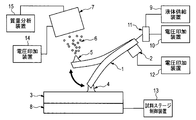
- FIG. 1 is a probe having a flow passage through which liquid passes
- 2 is a vibration providing means for vibrating the probe
- 3 is a substrate
- 4 is a liquid bridge formed between the probe 1 and the substrate 3
- 5 is a Taylor cone
- 6 is a charged fine droplet
- 7 is an ion take-in part having an ion extraction electrode for taking ions into the mass spectrometer
- 8 is a sample stage for supporting the substrate.
- 9 is a liquid supply device for supplying a liquid to the probe 1
- 10 is a voltage application device
- 11 is a conductive channel
- 12 is a voltage application device
- 13 is a sample stage control device
- 14 is a voltage application device
- 15 is mass spectrometry. Device.
- the liquid supplied from the liquid supply device 9 forms a liquid bridge 4 between the substrate 3 and the probe 1. Further, the liquid that contributes to the liquid bridge 4 becomes the micro droplet 6 that is charged by the vibration of the probe 1 and the electric field generated by the voltage application device 10 and the voltage application device 14, thereby taking up the component to be measured as ions. It becomes possible to import the data into the unit 7.
- the probe is a means for applying a liquid onto the substrate, a means for acquiring a substance, a means for transferring a liquid to a suitable position for ionization, and a Taylor cone for ionization. It is a forming means.
- the liquid supply device 9 is a solvent for dissolving the analyte contained in the sample fixed on the substrate 3 or a mixed solution of the analyte and the solvent dissolving the analyte (hereinafter referred to as these solvents). And the confusion solution are simply referred to as liquid).
- the liquid supplied from the liquid supply device 9 is guided to the flow channel inside the probe 1 via the conductive flow channel 11, and at this time, from the voltage application device 10 via the conductive flow channel 11. A voltage is applied to the liquid. Either DC voltage, AC voltage, pulse voltage, or zero volts is applied to the liquid.
- a probe means these generic names, when the whole or a part of the electroconductive flow path 11 is included in the flow path inside the probe 1 or connection piping.
- the probe in the present embodiment is a general term for these. That is, it is sufficient that at least a part of the material forming the probe is conductive. Examples of the conductive material include metals and semiconductors, and any material may be used as long as it has a property of showing a reproducible and constant voltage value when a voltage is applied from a voltage application device. . That is, in this embodiment, the voltage is applied to the liquid by applying a voltage to the conductive portion of the probe.
- Applying a voltage to the probe in this embodiment means that a potential different from the potential of an ion extraction electrode described later is applied to a conductive portion that forms at least a portion of the probe, and a conductive portion that forms at least a portion of the probe It means that an electric field is formed between ion extraction electrodes described later. As long as this electric field is achieved, the voltage applied here may be zero volts.
- the material of the flow path 11 may be a conductive substance, and for example, stainless steel, gold, platinum, or the like can be used.
- connection pipe for connecting the probe 1, the conductive flow path 11 and the liquid supply device 9 for example, a thin tube for supplying a small volume of liquid, such as a thin tube such as a silica capillary or a metal capillary, can be used.
- the electrical conductivity may be any of an insulator, a conductor, and a semiconductor.
- the conductive flow path 11 may be a part of a flow path in which the liquid supplied from the liquid supply device 9 passes through the inside of the probe 1 and is led to the tip of the probe 1 on the side opposite to the liquid supply device 9.
- the position is not particularly limited.
- all or a part of the conductive flow path 11 may be included in the flow path inside the probe 1 or the connection pipe, and as such a configuration, a conductive material such as a stainless steel wire, a tungsten wire, or a platinum wire is used.
- a probe or the like in which an object is inserted into a silica capillary can be used.
- the voltage applied to the conductive channel 11 propagates to the probe 1 and the voltage is applied to the liquid in the channel inside the probe 1. Details of such an embodiment are described in the second embodiment herein.
- the probe 1 is an insulator, the voltage applied to the conductive channel 11 cannot propagate to the probe 1, but the voltage is applied to the liquid flowing in the channel 11, and the liquid is applied to the probe 1. Therefore, even when no voltage is propagated to the probe 1, a voltage is applied to the liquid to charge the liquid.
- the liquid supplied from the liquid supply device 9 is provided from the tip of the probe 1 onto the substrate 3.
- the sample may be immobilized on the substrate in advance, and a specific component as an analyte contained in the sample on the substrate 3 may be dissolved in the solvent supplied from the probe 1, or the analyte A mixed solution in which is mixed with a solvent may be supplied onto the substrate 3.
- the probe 1 further vibrates in the above configuration.
- the vibration of the probe 1 means that the probe 1 moves so that the position of the tip of the probe 1 on the substrate 3 side is spatially displaced.
- the probe bend and vibrate in a direction crossing the axial direction of the probe.
- the probe 1 can be vibrated by applying mechanical vibration from the vibration providing means 2, the spontaneous resonance of the probe 1 may be used as it is without using the vibration supply means 2.
- the natural vibration frequency of the primary mode of a cantilever type object can be expressed by the length, density, cross-sectional area, Young's modulus, and second-order moment of the beam. Since the probe in this embodiment is also similar to a cantilever type probe, the material and size of the probe, the type and volume of the liquid supplied to the probe, and the magnitude of the electric field between the probe and the ion capturing part By adjusting, the natural vibration frequency of the probe can be controlled. In the examples described later, silica is used as the material of the probe, but other materials may be used, for example, silicon, polymer material, metal material can be used, and probes having different material density and Young's modulus can be used. good.
- the vibration supply means 2 may be any object that generates vibration, and for example, a piezo element or a vibration motor can be used.
- the vibration of the probe 1 may be either continuous vibration or intermittent vibration, and the vibration frequency may be either a resonance frequency or a non-resonance frequency.
- the timing of applying a voltage to the liquid and the timing of supplying vibration to the probe 1 can be arbitrarily determined.
- the frequency and amplitude of vibration of the probe 1 can be set to arbitrary values, and may be held at a constant value or may be modulated.
- the frequency of vibration can be arbitrarily adjusted by changing the voltage value or current value output from the voltage application device 12 electrically connected to the vibration providing means 2.
- the magnitude of the amplitude is set so that the formation of the liquid bridge and the generation of ionization are compatible, and it is desirable to change the setting as appropriate when the type of the probe and the magnitude of the electric field are changed.
- two independent vibration providing means 2 are brought into contact with the probe 1 to generate vibrations in directions orthogonal to each other, whereby bending vibration in an arbitrary direction can be given to the probe 1.
- vibrations in directions orthogonal to each other, whereby bending vibration in an arbitrary direction can be given to the probe 1.
- Examples of such types of vibration include uniaxial vibration, rotational motion, and spiral motion.
- uniaxial vibration the probe vibrates in a uniaxial direction at a specific frequency and amplitude.
- the vibration of a cantilever type probe corresponds to this, and the vibration can be approximated by a sine wave.
- the probe vibrates at a specific frequency and amplitude by giving vibrations in biaxial directions perpendicular to each other to the probe. At this time, the vibration can be approximated by combining two sine waves and is known as a Lissajous figure.
- vibration can be stably applied to the probe 1 by sandwiching the probe 1 with a plurality of vibration providing means 2 facing each other.
- the state in which the probe 1 and the substrate 3 are connected via the liquid and the state in which the probe 1 and the substrate 3 are separated can be generated separately.
- a state in which two objects are connected via a liquid is generally called liquid bridge.
- the liquid bridge 4 refers to a state in which the liquid supplied from the probe 1 is in physical contact with at least both the probe 1 and the substrate 3.
- the step of forming an electric field for generating ions between the conductive portion of the probe and the ion extraction electrode is achieved by alternately changing one end of the probe by vibrating. By changing the position of one end of the probe due to vibration, it is possible to set a suitable arrangement relationship in which each of the steps (i) and (ii) is performed.
- the liquid bridge 4 is formed by supplying the liquid from the probe 1 continuously or intermittently.
- the probe 1 may or may not touch the substrate 3.
- the liquid bridge 4 can be formed more stably.
- the liquid that has formed the liquid bridge 4 approaches the ion intake portion 7 having an ion extraction electrode electrically connected to the voltage application device 14.
- the liquid is ionized by the probe 1 due to an electric field between the potential of the liquid itself to which a voltage is applied through the conductive channel 11 and the potential of the ion extraction electrode to which the voltage is applied by the voltage application device 14. It moves to the side surface on the intake portion 7 side to form the Taylor cone 5.
- the side surface means a portion where electrospray is generated.
- a Taylor cone 5 is formed on a continuous surface that forms the major axis direction of the probe. This position depends on the electric field between the ion intake 7 and the liquid, the wettability of the probe 1 with the liquid, and the like. Since it is affected, the Taylor cone 5 may be formed at a position including other surfaces.
- An electric field is increased at the tip of the Taylor cone 5, electrospray is generated from the mixed solution, and minute charged droplets 6 are generated.
- the charged droplets undergo Rayleigh splitting, and ions of specific components can be generated.
- the charged droplets and ions are guided to the ion take-in unit 7 according to the flow of the air current and the electric field.
- the vibration of the probe includes a movement in a direction close to the ion capturing portion 7 so that an electric field around the solution forming the Taylor cone increases.
- Rayleigh splitting refers to a phenomenon in which the charged droplet 6 reaches the Rayleigh limit, and excess charge in the charged droplet is released as a secondary droplet.
- the liquid forms a Taylor cone
- electrospray containing charged droplets is generated from the tip of the Taylor cone
- components contained in the charged droplets are generated as gas phase ions while Rayleigh splitting occurs. It has been known.
- the ion take-in unit 7 is heated to a specific temperature between room temperature and several hundred degrees, and a voltage is further applied. At this time, it is necessary to adjust the voltage applied to the liquid from the voltage application device 10 and the voltage applied to the ion extraction electrode by the voltage application device 14 so that an appropriate electric field is generated so that ions are generated.
- the voltage from the voltage application device 14 any one of a DC voltage, an AC voltage, a pulse voltage, zero volts, or any combination thereof can be used.
- the electric field for generating ions depends on the potential applied to the conductive flow path 11 which is the conductive portion of the probe, the potential of the ion intake portion 7, and the distance between the liquid and the ion intake portion 7. It is prescribed. Therefore, it is necessary to set these so that an appropriate electric field is generated according to the type of the substance or solvent to be ionized.
- the ions are introduced into the mass spectrometer 15 connected to the ion take-in unit 7 through the differential exhaust system, and the mass-to-charge ratio of the ions is measured there.
- the mass spectrometer 15 an arbitrary device such as a quadrupole mass spectrometer, a time-of-flight mass spectrometer, a magnetic field deflection mass spectrometer, an ion trap mass spectrometer, or an ion cyclotron mass spectrometer should be used. Can do.
- a mass spectrum can also be obtained by measuring the correlation between the mass-to-charge ratio of ions (mass number / charge number, hereinafter referred to as m / z) and the amount of ions generated.
- the size of the Taylor cone 5 varies depending on the flow rate of the liquid, the composition of the liquid, the tip shape of the probe 1, the vibration frequency of the probe 1, the magnitude of the electric field, and the like.
- the Taylor cone 5 is very small, its form may not be confirmed with a microscope or the like, but it is sufficient that ions are stably generated.
- the timing of the step of forming the liquid bridge 4 with the liquid and the step of electrospraying at the tip of the Taylor cone and ionizing the substance are separated, Processes are performed at different timings.
- the timing for forming the liquid bridge and the solution in which the measurement target component is dissolved are controlled to be separated from the timing for generating the electrospray.
- electrospray is not generated at the timing of forming the liquid bridge, and at this timing, only the charge is supplied to the liquid, and the release of the charge from the liquid is suppressed.
- a sufficient charge is accumulated in the liquid, and electrospray can be generated efficiently.
- the vibration energy of the probe is applied to the liquid that forms the electrospray, increasing the charge density at the tip of the Taylor cone and promoting the generation of electrospray. It is thought to produce an effect.
- the interaction time between the solid sample surface and the probe is reduced, and there is an effect of suppressing damage to the solid sample surface with large irregularities.
- the probe may cut the sample surface and the surface shape may change.
- the volume of the liquid constituting the liquid bridge 4 can be easily controlled by adjusting the formation time of the liquid bridge 4 by controlling the liquid flow rate, the vibration amplitude and the vibration frequency of the probe 1. it can. Therefore, when supplying the mixed solution in which the analyte is mixed with the solvent in advance from the probe, the amount of the analyte to be ionized can be finely adjusted.
- the size of the region in contact with the liquid bridge 4 can be controlled by adjusting the formation time of the liquid bridge 4. It becomes possible to ionize only the components in a region of an arbitrary size.
- the position of the substrate stage 8 is changed by the sample stage control device 13 so that the coordinates of the ionized position in the sample can be controlled. Furthermore, by associating the coordinates of the ionized position with the obtained mass spectrum, a two-dimensional distribution of the mass spectrum can be obtained.
- Data obtained by this method is three-dimensional data composed of coordinates (X coordinate and Y coordinate) of ionized positions and a mass spectrum. After performing ionization and acquisition of mass spectra at different positions, selecting an ion amount with an arbitrary mass-to-charge ratio and displaying its distribution makes it possible to obtain a mass image for each component, and a specific surface of the sample. The distribution of components can also be captured.
- the sample moving method may be set so that the liquid bridge 4 formed by the probe 1 scans in an arbitrary plane to be measured.
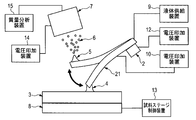
- a voltage may be applied to the liquid via a probe 21 having a flow path through which the liquid passes.
- the probe 21 is electrically connected to the voltage application device 10, and a voltage is applied to the liquid supplied from the liquid supply device 9 via the probe 21.
- applying a voltage to the probe means applying an electric potential different from the electric potential of the ion extraction electrode to a conductive portion that forms at least a part of the probe so that ions can be generated. Is formed between the ion extraction electrode and the probe, and as long as this electric field is achieved, the voltage applied to the conductive site forming at least a portion of the probe may be zero volts.
- the material of the probe 21 may be a conductive substance, and for example, a metal such as stainless steel, gold, or platinum, or a dielectric material such as glass with a metal partially covered can be used.
- a probe 31 that can supply a plurality of types of liquids may be used.
- the probe 31 has a first flow path 32 for supplying a liquid and a second flow path 33 for supplying a liquid.
- a liquid bridge 4 is formed between the first flow path 32 and the substrate 3.
- the liquid exiting the second channel 33 does not form a liquid bridge.
- different potentials can be independently applied to the first liquid flowing in the flow path 32 and the second liquid flowing in the flow path 33 through different conductive flow paths.
- Another type of liquid may flow through the first flow path 32 and the second flow path 33, or the same type of liquid may flow.
- a solvent that dissolves the components on the sample surface is introduced into the first flow path 32, and a solvent that contains a molecular species that reacts with a specific component contained in the first liquid is added to the second channel.
- the specific component can be selectively ionized by introducing it into the flow path 33.
- a liquid for contacting with the sample surface and forming a liquid bridge is introduced into both the first flow path 32 and the second flow path 33.
- the side surface of the probe 31 is always washed with the liquid exiting from the second flow path 33, thereby preventing contamination of the side surface of the probe tip and preventing a reduction in the spatial resolution of the mass image.
- the probe which contains three or more types of flow paths may be used.
- a protrusion made of a metal wire or the like is formed in the vicinity of the tip portion of the probe, thereby forming a Taylor cone and ionizing it. Can also be stabilized.
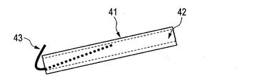
- the probe 41 is formed with a flow path 42 for flowing a liquid.
- the metal wire 43 is inserted into the probe 41 to form a structure in which a part of the metal wire 43 is exposed at the tip portion of the probe 41.
- a metal wire such as platinum is inserted into the flow path 42, and the platinum wire is exposed at the tip portion of the probe 41, and then bent toward the ion intake portion 7 (FIG. 4A).
- the other end of the platinum wire contacts the inner wall portion of the flow path 42 and is processed into a shape that does not easily fall off from the probe 41.
- the liquid in which the liquid bridge is formed between the probe 41 and the substrate 3 moves spontaneously along the metal line portion of the probe 41, so that the Taylor cone is stably formed at the protrusion portion. Is done. In this way, by forming the minute protrusions, the charged liquid can stay at the tip portion of the probe 41 and can be stably ionized.
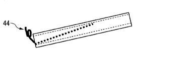
- the protrusion is not necessarily in the form of the metal wire 43, and an arbitrarily bent metal wire 44 (FIG. 4B) or a straight metal wire 45 (FIG. 4C) can also be used. Substances other than metal wires can also be used.
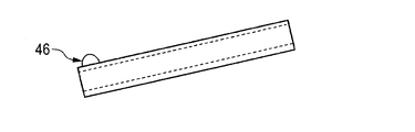
- the protrusion 46 (FIG. 4D) can be formed by installing a polymer material such as an epoxy-based resin at the probe tip.
- the sample to be ionized is not particularly limited.
- organic compounds composed of macromolecules such as lipids, sugars, and proteins are targeted for ionization, according to the method of this embodiment, these substances can be easily soft ionized.
- each ion has a specific mass-to-charge ratio
- only specific ions can be separated by adjusting the electric field around the ions. That is, specific components in the mixture can be extracted and purified.
- a method for separating only specific components there is a method in which a plurality of ion species are introduced into a vacuum chamber, and after separation by an electric field, only specific ion components are accumulated on a substrate in the vacuum chamber. .
- the substrate on which the components are accumulated can be taken out of the vacuum chamber, and the components can be separated from the substrate using an appropriate solvent.
- an object such as an artificial organ can be installed in the vacuum chamber, and the separated ions can be directly applied.
- a method for providing an electric field a quadrupole electrode, an ion trap electrode, and the like can be given.
- a substance such as a protein having an affinity for a specific part of a living body can be separated from a plurality of components contained in a disrupted extract of cultured cells. If the separated specific component is applied to the surface of the substance, the function of the component can be added to the substance. Moreover, if the component which reacts specifically with a specific disease site
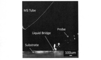
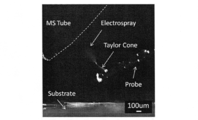
- FIGS. 5A and 5B show the result of observation with a high-speed camera of a state where liquid bridges are formed and a state where ions are generated using the method of the present invention.
- an ion capturing portion MS Tube
- TSQ7000 Thermo Fisher Scientific
- a silica capillary that can supply liquid from the tip portion to the substrate is used in a state of being connected to a metal needle of a syringe, and a voltage is applied through a voltage applying device connected to the metal needle.
- the syringe is fixed to a syringe pump, and a constant flow rate of liquid can be delivered from the syringe to the probe tip.
- a voltage of 3 to 6 kV was applied to the probe.
- the solvent flow rate was 0.15 microliters per minute.
- the angle between the substrate and the probe was about 20 degrees, and the angle between the major axis of the metal tube serving as the ion take-in portion and the substrate was about 40 degrees.
- MS Tube was connected to TSQ7000, and a potential of 37.5 V was applied to the connection portion, and the temperature was set to 300 degrees.
- the probe is vibrated in a spontaneous resonance mode, it is observed that the state closest to the substrate shown in FIG. 5A and the state shown in FIG. 5B that is the farthest from the substrate and close to the MS Tube are alternately taken. It was.
- the spatial electric field around the Taylor cone is mainly affected by the potential provided to the probe, the potential of the MS Tube, and the distance between the MS Tube and the charged liquid.
- the acceleration of the probe becomes maximum.
- the force applied to the charged liquid adhering to the probe in the direction of the MS tube perpendicular to the long axis of the probe is maximized, and the dynamic action causes the formation of the Taylor cone and the formation of microdroplets. It is thought to produce a promoting effect.
- the vibration frequency is about 200 Hertz
- the displacement of the probe at the position where the liquid bridge is formed and the position where the electrospray is formed is about 500 micrometers. It was lost. It was also confirmed that when the probe length was increased, the frequency of vibration decreased.
- the spontaneous resonance of the probe was used, but it was confirmed that the probe vibrates even when the vibrator was brought into contact with a part of the probe. In this way, vibration can be controlled by changing the length of the probe. In addition to this, it is considered that vibration can be controlled by changing each parameter.
- the natural vibration frequency of the first-order mode of a cantilever type object can be expressed by the length, density, cross-sectional area, Young's modulus, and second-order moment of the beam. Since the probe in this embodiment is similar to the cantilever probe, the material and size of the probe, the type and volume of the liquid supplied to the probe, and the magnitude of the electric field between the probe and the MS tube are adjusted. This is because it is considered that the vibration of the probe can be controlled.
- the formation and ionization of the Taylor cone could be stabilized.
- a metal wire such as platinum was inserted into the capillary and the platinum wire was exposed at the tip of the capillary and protruded in the direction of the MS tube, the same experiment was conducted. It was confirmed that the Taylor cone was stably formed by moving spontaneously along the platinum wire portion.
- Example 2 Mass spectrum acquisition and one-dimensional mapping of mouse pancreas slice (mass-to-charge ratio: 50 to 1000) The result at the time of ionizing a biological component using the method of this invention is shown.
- the sample was prepared by slicing mouse pancreatic tissue to a thickness of about 10 micrometers with a cryomicrotome and immobilizing it on a glass substrate.
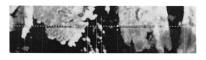
- the form of the sample ionized by the method of the present invention is shown in FIG.
- the pancreatic tissue section is shown with white contrast, and there are five sections on the glass substrate.
- a sample existing on a line segment connecting the two points indicated by the tip of the sample with a straight line was ionized by the method of the present invention.
- the probe vibrated and liquid bridges were intermittently formed on the sample surface and the tip of the probe.
- the sample was set to move uniaxially, and set to move 0.05 mm every 2 seconds.
- a quadrupole mass spectrometer (TSQ7000; Thermo Fisher Scientific) was used as the mass spectrometer.
- the mass to charge ratio to be measured was set to 50 to 1000.
- Other experimental conditions are the same as those described in Example 1.
- Fig. 7 shows the mass spectrum obtained by the measurement.
- m / z corresponding to these fragments was hardly detected.
- the component of the living tissue can be soft ionized under an atmospheric pressure environment by the method of the present invention.
- FIG. 8B shows the ion intensity obtained when the dotted line portion of FIG. 8A, which is an enlarged optical microscope image of the sample shown in FIG. 6, is scanned.
- the horizontal axis represents time
- the vertical axis represents the mass-to-charge ratio
- the ion amount is shown in shades. Since the probe is scanning the sample of FIG. 8A with time, in FIG. 8B, the horizontal axis corresponds to the place where the ions on the sample are generated, and the more white the ions are displayed, the more the ions are displayed. The amount is large.
- 9A and 9B show mass spectra having a mass-to-charge ratio of 1000 to 2000 obtained using the method of the present invention.
- the sample is a mouse pancreatic tissue section.
- the sample and the probe tip were intermittently brought close to each other, and the measurement was performed while confirming whether or not the liquid bridge was formed. In other words, it was confirmed that the formation and disappearance of the liquid bridge were repeated in the state where the liquid bridge was intermittently held without scanning the sample and in the state where the distance between the probe and the sample was separated and the liquid bridge disappeared.
- the change over time of the mass spectrum was measured.
- 9A and 9B show experimental results when each state is measured continuously four times.
- FIG. 9A shows a mass spectrum
- FIG. 9A shows a mass spectrum
- FIG. 9A shows a change in ion intensity with time. From FIG. 9A, it was confirmed that a plurality of ions were generated in a mass to charge ratio range of 1000 to 2000. Next, from the result of FIG. 9B, it was confirmed that the generation and disappearance of these ions correspond to the presence or absence of liquid crosslinking. From this, it can be seen that the components on the surface of the sample are dissolved in the liquid bridge due to the formation of the liquid bridge and then ionized. In addition, the ionic strength decreased with time in the state where the liquid bridge was formed.
Abstract
The purpose of the present invention is to easily carry out soft ionization when ionizing a minutely small amount of a substance in an atmosphere environment. A method for ionizing a substance contained in a liquid, the ionization method being characterized by involving: a step for supplying a liquid from a probe to a substrate and for forming a liquid cross-link between the probe and the substrate by means of the liquid in which the substance is dissolved; a step for vibrating the substrate; and a step for forming an electric field between an ion extraction electrode and the conductive site of the probe with which the liquid is in contact.
Description
本発明は、物質のイオン化方法およびこれを用いた質量分析方法に関する。また、本発明は、物質の抽出方法、精製方法に関する。
The present invention relates to a substance ionization method and a mass spectrometry method using the same. The present invention also relates to a substance extraction method and a purification method.
成分分析法の一つである質量分析法は、試料中の成分をイオン化し、その質量電荷比(質量数/電荷数)を計測する技術である。
Mass spectrometry, one of the component analysis methods, is a technique for ionizing components in a sample and measuring the mass-to-charge ratio (mass number / charge number).
近年、固体試料表面に存在している成分の分布を画像化する技術が開発されている。例えば、特定の成分の分布を質量画像として可視化することで、試料の状況を判断することができる。このような技術の一例として、ガン組織を有する病理検体の質量画像を元に、病理診断の根拠となるデータを示す方法が開発されている。質量画像は、通常、試料表面の複数の測定点で試料をイオン化し、発生したイオン化の質量電荷比をそれぞれの測定点ごとに求め、試料表面の位置とイオンの情報を対応づけることにより取得する。そのため、得られる質量画像の空間分解能を向上するために、試料表面の微小領域をイオン化する技術が求められている。
Recently, a technique for imaging the distribution of components existing on the surface of a solid sample has been developed. For example, the status of the sample can be determined by visualizing the distribution of specific components as a mass image. As an example of such a technique, a method has been developed that shows data as a basis for pathological diagnosis based on a mass image of a pathological specimen having cancer tissue. A mass image is usually obtained by ionizing a sample at a plurality of measurement points on the sample surface, obtaining a mass-to-charge ratio of the generated ionization for each measurement point, and associating the position of the sample surface with ion information. . Therefore, in order to improve the spatial resolution of the obtained mass image, a technique for ionizing a minute region on the sample surface is required.
試料表面の微小領域の成分をイオン化する技術として、これまでに、振動するカンチレバー型プローブを用いて、固体物質表面の成分をイオン化する方法が提案されている(特許文献1、非特許文献1)。この方法では、一端に尖った先端を有し、逆の端部をカンチレバーに固定したプローブを、プローブの尖った先端が試料と質量分析装置のイオン取り込み口の前との間を往復するように運動させる。試料の微小領域に接触して試料の成分が付着したプローブの尖った先端部分に、イオン取り込み口の前で電圧やレーザー光を照射することで、プローブの尖った先端に付着した当該微小領域の成分のみをイオン化することが可能になる。
As a technique for ionizing a component in a minute region on the sample surface, a method for ionizing a component on the surface of a solid substance using a vibrating cantilever probe has been proposed (Patent Document 1, Non-Patent Document 1). . In this method, a probe having a pointed tip at one end and the opposite end fixed to a cantilever is set so that the pointed tip of the probe reciprocates between the sample and the ion intake port of the mass spectrometer. Exercise. By irradiating the pointed tip of the probe, which is in contact with the sample's minute region and adhering to the sample component, with voltage or laser light in front of the ion intake port, the minute region attached to the pointed tip of the probe Only the components can be ionized.
また、固体試料表面の微小領域に溶媒を付与して当該微小領域に存在する成分を溶解し、溶解した成分を大気圧環境下でイオン化する方法が提案されている(非特許文献2)。この方法では、固体試料中の成分を溶解するための溶媒を試料の表面に供給するための第一のキャピラリと、成分が溶媒に溶解した混合溶液をイオン化部分まで移動させるための第二のキャピラリとが用いられている。固体試料の表面に二本のキャピラリが近接した状態で、第一のキャピラリから溶媒が供給されることで、二本のキャピラリの先端部と試料表面との間に液架橋が形成される。この液架橋において固体試料の接触部分のみが溶解された後に、第二のキャピラリに導入される。溶媒には高電圧が印加されており、第二のキャピラリの先端部でイオン化される。この方法を用いることで、微小領域のイオン化が可能となる。また、大気圧環境下でイオン化をすることにより、処理時間の短縮化および装置の小型化が可能となり、特に数多くの試料の分析を行う際に有利である。
Also, a method has been proposed in which a solvent is applied to a minute region on the surface of a solid sample to dissolve components present in the minute region, and the dissolved component is ionized under an atmospheric pressure environment (Non-patent Document 2). In this method, a first capillary for supplying a solvent for dissolving the components in the solid sample to the surface of the sample, and a second capillary for moving the mixed solution in which the components are dissolved in the solvent to the ionization portion And are used. By supplying the solvent from the first capillary while the two capillaries are close to the surface of the solid sample, a liquid bridge is formed between the tips of the two capillaries and the sample surface. In this liquid bridge, only the contact portion of the solid sample is dissolved and then introduced into the second capillary. A high voltage is applied to the solvent and it is ionized at the tip of the second capillary. By using this method, it is possible to ionize a minute region. Further, by performing ionization under an atmospheric pressure environment, the processing time can be shortened and the apparatus can be miniaturized, which is particularly advantageous when many samples are analyzed.
なお、生体組織などの生物由来の材料の質量分析においては、イオン化する際に分子が非選択的に切断されて断片化した場合、成分の特定が困難になるため、生体成分を壊すことなくイオン化するソフトイオン化も求められている。
In mass spectrometry of biological materials such as biological tissue, if molecules are non-selectively cleaved and fragmented during ionization, it becomes difficult to specify the components, so ionization without breaking biological components. Soft ionization is also required.
特許文献1および非特許文献1に開示されている方法では、測定される成分は、原子または少数の原子から構成される分子である。この方法では、脂質・糖・蛋白質などの高分子をイオン化しようとすると、尖ったプローブ先端に高分子の構造を保持したまま付着させ、その後に脱離・ソフトイオン化(分子構造が切断されずにイオン化される)を発生させることが困難であるという課題がある。
In the methods disclosed in Patent Document 1 and Non-Patent Document 1, the component to be measured is an atom or a molecule composed of a small number of atoms. In this method, when trying to ionize macromolecules such as lipids, sugars, and proteins, they are attached to the tip of a sharp probe while retaining the structure of the macromolecule, and then desorption / soft ionization (without breaking the molecular structure). There is a problem that it is difficult to generate (ionized).
非特許文献2に開示されている方法では、二本のキャピラリの先端部の最近接距離よりも小さなサイズの液架橋を作ることが困難であり、イオン化する領域を小さくすることによる空間分解能の向上が困難であるという課題がある。また、この方法では、二本のキャピラリを精度良く合わせて近接させるための仕組みが必要であり、装置を構成する部品点数が増加し、装置自体も複雑なものになるという課題もある。
In the method disclosed in Non-Patent Document 2, it is difficult to form a liquid bridge having a size smaller than the closest distance between the tip ends of two capillaries, and the spatial resolution is improved by reducing the ionization region. There is a problem that is difficult. In addition, this method requires a mechanism for bringing two capillaries close together with high accuracy, increasing the number of parts constituting the apparatus and complicating the apparatus itself.
本発明のイオン化方法は、液体に含まれる物質のイオン化方法であって、(i)プローブから基板上に液体を供給し、該プローブと該基板との間に該物質を含む液体による液架橋を形成する工程と、(ii)前記液体が接する前記プローブの導電性部位とイオン引き出し電極の間で電界を形成する工程と、を有することを特徴とする。
The ionization method of the present invention is a method for ionizing a substance contained in a liquid, and (i) a liquid is supplied from a probe onto a substrate, and liquid crosslinking with the liquid containing the substance is performed between the probe and the substrate. And (ii) forming an electric field between the conductive portion of the probe in contact with the liquid and the ion extraction electrode.
本発明によれば、大気圧環境下で微小な量の物質をイオン化するにあたり、より容易に空間分解能の向上を達成することができるようになる。
According to the present invention, when ionizing a minute amount of a substance under an atmospheric pressure environment, it is possible to more easily improve the spatial resolution.
以下、本発明の方法について図面を示して説明する。本発明を実施する形態の一例を図1に示す。図1において、1は液体が通過する流路を内部に有するプローブ、2はプローブ1を振動させる振動提供手段、3は基板、4はプローブ1と基板3との間に形成された液架橋、5はテイラーコーン、6は帯電した微小液滴、7は質量分析装置にイオンを取り込むためのイオン引き出し電極を有するイオン取込部、8は基板を支持する試料ステージである。9はプローブ1に液体を供給する液体供給装置、10は電圧印加装置、11は導電性の流路、12は電圧印加装置、13は試料ステージ制御装置、14は電圧印加装置、15は質量分析装置である。
Hereinafter, the method of the present invention will be described with reference to the drawings. An example of an embodiment for carrying out the present invention is shown in FIG. In FIG. 1, 1 is a probe having a flow passage through which liquid passes, 2 is a vibration providing means for vibrating the probe 1, 3 is a substrate, 4 is a liquid bridge formed between the probe 1 and the substrate 3, 5 is a Taylor cone, 6 is a charged fine droplet, 7 is an ion take-in part having an ion extraction electrode for taking ions into the mass spectrometer, and 8 is a sample stage for supporting the substrate. 9 is a liquid supply device for supplying a liquid to the probe 1, 10 is a voltage application device, 11 is a conductive channel, 12 is a voltage application device, 13 is a sample stage control device, 14 is a voltage application device, and 15 is mass spectrometry. Device.
本発明においては、液体供給装置9から供給された液体は基板3とプローブ1との間で液架橋4を形成する。さらに、液架橋4に寄与した液体が、プローブ1の振動と電圧印加装置10及び電圧印加装置14による電界とによって帯電した微小液滴6になることにより、測定対象の成分をイオンとしてイオン取込部7に取り込むことが可能となる。
In the present invention, the liquid supplied from the liquid supply device 9 forms a liquid bridge 4 between the substrate 3 and the probe 1. Further, the liquid that contributes to the liquid bridge 4 becomes the micro droplet 6 that is charged by the vibration of the probe 1 and the electric field generated by the voltage application device 10 and the voltage application device 14, thereby taking up the component to be measured as ions. It becomes possible to import the data into the unit 7.
すなわち、本形態においては、プローブが基板上への液体の付与手段であり、物質の取得手段であり、イオン化のための好適な位置への液体の移送手段であり、イオン化のためのテイラーコーンの形成手段となっている。
That is, in this embodiment, the probe is a means for applying a liquid onto the substrate, a means for acquiring a substance, a means for transferring a liquid to a suitable position for ionization, and a Taylor cone for ionization. It is a forming means.
液体供給装置9は、基板3上に固定された試料に含まれる被分析物を溶解するための溶媒又は被分析物と被分析物を溶解している溶媒との混合溶液(以下、これらの溶媒と混同溶液とをあわせて単に液体と記す)を供給する。液体供給装置9から供給された液体は、導電性の流路11を経由してプローブ1内部の流路へと導かれ、その際に、導電性の流路11を介して電圧印加装置10から液体に電圧が印加される。液体には直流電圧、交流電圧、パルス電圧又はゼロボルトのいずれかが印加される。
The liquid supply device 9 is a solvent for dissolving the analyte contained in the sample fixed on the substrate 3 or a mixed solution of the analyte and the solvent dissolving the analyte (hereinafter referred to as these solvents). And the confusion solution are simply referred to as liquid). The liquid supplied from the liquid supply device 9 is guided to the flow channel inside the probe 1 via the conductive flow channel 11, and at this time, from the voltage application device 10 via the conductive flow channel 11. A voltage is applied to the liquid. Either DC voltage, AC voltage, pulse voltage, or zero volts is applied to the liquid.
なお、本実施形態において、プローブとは、プローブ1の内部の流路や接続用配管に導電性の流路11の全部又は一部分が包摂されている場合は、これらの総称を意味する。また、プローブ1の内部の流路や接続用配管に導電性の流路11が包摂されていない場合にも、本実施形態におけるプローブは、広義には、これらの総称を意味する。すなわち、プローブを形成する素材の少なくとも一部分が導電性であればよい。導電性を有する材料には、金属・半導体などが挙げられるが、電圧印加装置から電圧が印加された場合に、再現性のある一定の電圧値を示す性質を有するものであればいかなるものでもよい。つまり、本実施形態において、プローブの導電性部位に電圧を印加することで、液体に電圧を印加している。
In addition, in this embodiment, a probe means these generic names, when the whole or a part of the electroconductive flow path 11 is included in the flow path inside the probe 1 or connection piping. Further, even when the conductive flow path 11 is not included in the flow path inside the probe 1 or the connection pipe, the probe in the present embodiment is a general term for these. That is, it is sufficient that at least a part of the material forming the probe is conductive. Examples of the conductive material include metals and semiconductors, and any material may be used as long as it has a property of showing a reproducible and constant voltage value when a voltage is applied from a voltage application device. . That is, in this embodiment, the voltage is applied to the liquid by applying a voltage to the conductive portion of the probe.
本実施形態でプローブに電圧を印加するとは、後述のイオン引き出し電極の電位とは異なる電位を、プローブの少なくとも一部分を形成する導電性部位に付与し、プローブの少なくとも一部分を形成する導電性部位と後述のイオン引き出し電極の間で、電界を形成することを意味する。この電界が達成される限りにおいて、ここで印加される電圧がゼロボルトであってもよい。流路11の材料は導電性の物質であれば良く、例えばステンレス・金・白金などを用いることができる。
Applying a voltage to the probe in this embodiment means that a potential different from the potential of an ion extraction electrode described later is applied to a conductive portion that forms at least a portion of the probe, and a conductive portion that forms at least a portion of the probe It means that an electric field is formed between ion extraction electrodes described later. As long as this electric field is achieved, the voltage applied here may be zero volts. The material of the flow path 11 may be a conductive substance, and for example, stainless steel, gold, platinum, or the like can be used.
プローブ1、導電性の流路11及び液体供給装置9を接続する接続用配管としては、例えば、シリカキャピラリやメタルキャピラリ等の細管などの、微小体積の液体を供給する細管を利用することでき、その電気伝導性は絶縁体・導電体・半導体のいずれであってもよい。なお、導電性の流路11は、液体供給装置9から供給された液体がプローブ1内部を通り、液体供給装置9とは反対側のプローブ1の先端まで導かれる流路の一部分を構成すればよく、その位置は特に限定されない。例えば、プローブ1の内部の流路や接続用配管に導電性の流路11の全部又は一部分が包摂されていても良く、このような構成として、ステンレス線、タングステン線、白金線などの導電性物体がシリカキャピラリに挿入されたプローブなどを用いることができる。
As a connection pipe for connecting the probe 1, the conductive flow path 11 and the liquid supply device 9, for example, a thin tube for supplying a small volume of liquid, such as a thin tube such as a silica capillary or a metal capillary, can be used. The electrical conductivity may be any of an insulator, a conductor, and a semiconductor. The conductive flow path 11 may be a part of a flow path in which the liquid supplied from the liquid supply device 9 passes through the inside of the probe 1 and is led to the tip of the probe 1 on the side opposite to the liquid supply device 9. Well, the position is not particularly limited. For example, all or a part of the conductive flow path 11 may be included in the flow path inside the probe 1 or the connection pipe, and as such a configuration, a conductive material such as a stainless steel wire, a tungsten wire, or a platinum wire is used. A probe or the like in which an object is inserted into a silica capillary can be used.
プローブ1そのものが導電体の場合、導電性の流路11に印加された電圧がプローブ1に伝播し、プローブ1内部の流路の液体に電圧が印加される。このような実施形態の詳細は、本明細書の第二の実施形態に記載されている。一方、プローブ1が絶縁体の場合、導電性の流路11に印加された電圧はプローブ1に伝播することができないが、流路11に流れる液体に電圧が印加され、その液体がプローブ1に導入されるため、プローブ1に電圧が伝播されていない場合にも、液体に電圧を印加し、液体を帯電させることになる。
When the probe 1 itself is a conductor, the voltage applied to the conductive channel 11 propagates to the probe 1 and the voltage is applied to the liquid in the channel inside the probe 1. Details of such an embodiment are described in the second embodiment herein. On the other hand, when the probe 1 is an insulator, the voltage applied to the conductive channel 11 cannot propagate to the probe 1, but the voltage is applied to the liquid flowing in the channel 11, and the liquid is applied to the probe 1. Therefore, even when no voltage is propagated to the probe 1, a voltage is applied to the liquid to charge the liquid.
液体供給装置9から供給された液体は、プローブ1の先端から基板3上へと提供される。このとき、試料を基板上にあらかじめ固定化しておき、基板3上の試料に含まれる被分析物としての特定の成分をプローブ1から供給された溶媒に溶解させてもよいし、あらかじめ被分析物が溶媒と混合された混合溶液を基板3上に供給してもよい。
The liquid supplied from the liquid supply device 9 is provided from the tip of the probe 1 onto the substrate 3. At this time, the sample may be immobilized on the substrate in advance, and a specific component as an analyte contained in the sample on the substrate 3 may be dissolved in the solvent supplied from the probe 1, or the analyte A mixed solution in which is mixed with a solvent may be supplied onto the substrate 3.
これにより、大気圧環境下で微小な量の物質を高分解能でイオン化することが可能となる。
This makes it possible to ionize a minute amount of substance with high resolution in an atmospheric pressure environment.
本実施形態では、上記構成において、さらにプローブ1が振動する。なお、本発明でプローブ1が振動するとは、プローブ1の基板3側の先端の位置が空間的に変位するようにプローブ1が運動することをいう。特に、プローブの軸方向と交差する方向にプローブを屈曲振動させることが好ましい。振動提供手段2からの機械的な振動を与えることでプローブ1を振動させることができるが、振動供給手段2を利用せずに、プローブ1の自発的な共振をそのまま利用してもよい。
In this embodiment, the probe 1 further vibrates in the above configuration. In the present invention, the vibration of the probe 1 means that the probe 1 moves so that the position of the tip of the probe 1 on the substrate 3 side is spatially displaced. In particular, it is preferable that the probe bend and vibrate in a direction crossing the axial direction of the probe. Although the probe 1 can be vibrated by applying mechanical vibration from the vibration providing means 2, the spontaneous resonance of the probe 1 may be used as it is without using the vibration supply means 2.
一般に、片持ち梁型の物体の1次モードの固有振動周波数は、梁の長さ、密度、断面積、ヤング率、断面二次モーメントにより表現できることが知られている。本実施形態におけるプローブも片持梁型のプローブに類似しているため、プローブの材質、サイズ、プローブに供給する液体の種類と体積、およびプローブとイオン取込部との間の電界の大きさを調整することで、プローブの固有振動周波数を制御することができる。後述の実施例ではプローブの材質としてシリカを用いたが、他の材質でもよく、例えばシリコン、ポリマー材料、金属材料を使用することもでき、材料の密度・ヤング率の異なるプローブを利用しても良い。振動供給手段2は振動を発生させる物体であればよく、例えばピエゾ素子・振動モータなどを用いる事ができる。プローブ1の振動は、連続的振動・断続的振動のいずれであってもよく、振動周波数は共振周波数・非共振周波数のいずれでもよい。液体への電圧を印加するタイミング及び、プローブ1に振動を供給するタイミングは、任意に決定することができる。
In general, it is known that the natural vibration frequency of the primary mode of a cantilever type object can be expressed by the length, density, cross-sectional area, Young's modulus, and second-order moment of the beam. Since the probe in this embodiment is also similar to a cantilever type probe, the material and size of the probe, the type and volume of the liquid supplied to the probe, and the magnitude of the electric field between the probe and the ion capturing part By adjusting, the natural vibration frequency of the probe can be controlled. In the examples described later, silica is used as the material of the probe, but other materials may be used, for example, silicon, polymer material, metal material can be used, and probes having different material density and Young's modulus can be used. good. The vibration supply means 2 may be any object that generates vibration, and for example, a piezo element or a vibration motor can be used. The vibration of the probe 1 may be either continuous vibration or intermittent vibration, and the vibration frequency may be either a resonance frequency or a non-resonance frequency. The timing of applying a voltage to the liquid and the timing of supplying vibration to the probe 1 can be arbitrarily determined.
プローブ1の振動の周波数や振幅は、任意の値に設定することが可能であり、一定値に保持しても良いし、変調をかけても良い。例えば、振動提供手段2に電気的に接続した電圧印加装置12から出力される電圧値または電流値を変更することにより、振動の周波数を任意に調整することができる。また、振幅の大きさは、液架橋の形成とイオン化の発生がそれぞれ両立するように設定され、プローブの種類や電界の大きさを変更した場合には適宜設定を変更することが望ましい。
The frequency and amplitude of vibration of the probe 1 can be set to arbitrary values, and may be held at a constant value or may be modulated. For example, the frequency of vibration can be arbitrarily adjusted by changing the voltage value or current value output from the voltage application device 12 electrically connected to the vibration providing means 2. The magnitude of the amplitude is set so that the formation of the liquid bridge and the generation of ionization are compatible, and it is desirable to change the setting as appropriate when the type of the probe and the magnitude of the electric field are changed.
プローブ1の振動の方向についても、例えばプローブ1に2つの独立した振動提供手段2を接触させ、互いに直交する方向の振動を発生させることにより、任意の方向の屈曲振動をプローブ1に与えることができる。このような振動の種類としては、一軸振動・回転運動・螺旋運動などが挙げられる。一軸振動ではプローブが特定の周波数および振幅で一軸方向に振動する。例えばカンチレバー型のプローブの振動がこれに該当し、振動を正弦波で近似することができる。また、回転運動では、互いに直交する二軸方向の振動をプローブに与えることで、プローブが特定の周波数および振幅で振動する。このとき、振動は2つの正弦波の合成で近似することができ、リサージュ図形として知られている。
Regarding the direction of vibration of the probe 1, for example, two independent vibration providing means 2 are brought into contact with the probe 1 to generate vibrations in directions orthogonal to each other, whereby bending vibration in an arbitrary direction can be given to the probe 1. it can. Examples of such types of vibration include uniaxial vibration, rotational motion, and spiral motion. In uniaxial vibration, the probe vibrates in a uniaxial direction at a specific frequency and amplitude. For example, the vibration of a cantilever type probe corresponds to this, and the vibration can be approximated by a sine wave. In addition, in the rotational motion, the probe vibrates at a specific frequency and amplitude by giving vibrations in biaxial directions perpendicular to each other to the probe. At this time, the vibration can be approximated by combining two sine waves and is known as a Lissajous figure.
なお、プローブ1を対向する複数の振動提供手段2で挟むことで、プローブ1に安定して振動を与えることもできる。
It should be noted that vibration can be stably applied to the probe 1 by sandwiching the probe 1 with a plurality of vibration providing means 2 facing each other.
本実施形態においては、プローブ1が振動することにより、プローブ1と基板3とが液体を介してつながった状態と、プローブ1と基板3が離れた状態を分離して発生させることができる。2つの物体が液体を介してつながった状態は、一般に液架橋と呼ばれる。本実施形態において、液架橋4とは、プローブ1から供給された液体が、少なくとも、プローブ1及び基板3の両方に物理的に接触している状態のことをいう。
In this embodiment, when the probe 1 vibrates, the state in which the probe 1 and the substrate 3 are connected via the liquid and the state in which the probe 1 and the substrate 3 are separated can be generated separately. A state in which two objects are connected via a liquid is generally called liquid bridge. In the present embodiment, the liquid bridge 4 refers to a state in which the liquid supplied from the probe 1 is in physical contact with at least both the probe 1 and the substrate 3.
すなわち、本実施形態においては(i)プローブから基板上に液体を供給し、該プローブと該基板との間に該物質を含む液体による液架橋を形成する工程と、(ii)前記液体が接する前記プローブの導電性部位とイオン引き出し電極の間でイオンを発生させるための電界を形成する工程とが、プローブの一端を振動させることにより、交互に変更して達成されている。
振動によるプローブの一端の位置を異ならせることで、(i)工程と(ii)工程をそれぞれ実施する好適な配置関係に設定することができる。 That is, in the present embodiment, (i) a step of supplying a liquid from the probe onto the substrate and forming a liquid bridge with the liquid containing the substance between the probe and the substrate; and (ii) the liquid is in contact with the substrate. The step of forming an electric field for generating ions between the conductive portion of the probe and the ion extraction electrode is achieved by alternately changing one end of the probe by vibrating.
By changing the position of one end of the probe due to vibration, it is possible to set a suitable arrangement relationship in which each of the steps (i) and (ii) is performed.
プローブ1から連続的または断続的に液体が供給されることで、液架橋4が形成される。液架橋4が形成される際に、プローブ1は基板3に接してもよいし、接しなくてもよい。プローブ1が基板3に接する場合には、液架橋4をより安定して形成することができる。
The liquid bridge 4 is formed by supplying the liquid from the probe 1 continuously or intermittently. When the liquid bridge 4 is formed, the probe 1 may or may not touch the substrate 3. When the probe 1 is in contact with the substrate 3, the liquid bridge 4 can be formed more stably.
振動によりプローブ1が基板3から離れた状態において、液架橋4を形成していた液体は、電圧印加装置14と電気的に接続されたイオン引き出し電極を有するイオン取込部7に近づく。この際に、液体は、導電性の流路11を通じて電圧が印加された液体自身の電位と電圧印加装置14により電圧が印加されるイオン引き出し電極による電位との間の電界により、プローブ1のイオン取込部7側の側面に移動し、テイラーコーン5を形成する。ここで側面とは、エレクトロスプレーが発生する箇所を意味している。図1にはプローブの長軸方向を形成する連続面にテイラーコーン5が形成されているが、この位置はイオン取り込み部7と液体の間の電界、およびプローブ1の液体との濡れ性等により影響を受けるため、これ以外の面を含む位置にテイラーコーン5が形成されても良い。
In a state where the probe 1 is separated from the substrate 3 due to vibration, the liquid that has formed the liquid bridge 4 approaches the ion intake portion 7 having an ion extraction electrode electrically connected to the voltage application device 14. At this time, the liquid is ionized by the probe 1 due to an electric field between the potential of the liquid itself to which a voltage is applied through the conductive channel 11 and the potential of the ion extraction electrode to which the voltage is applied by the voltage application device 14. It moves to the side surface on the intake portion 7 side to form the Taylor cone 5. Here, the side surface means a portion where electrospray is generated. In FIG. 1, a Taylor cone 5 is formed on a continuous surface that forms the major axis direction of the probe. This position depends on the electric field between the ion intake 7 and the liquid, the wettability of the probe 1 with the liquid, and the like. Since it is affected, the Taylor cone 5 may be formed at a position including other surfaces.
テイラーコーン5の先端部分では電界が大きくなり、混合溶液からエレクトロスプレーが発生し、微小な帯電液滴6が発生する。電界の大きさを適当に設定することで、帯電液滴がレイリー分裂を生じ、特定の成分のイオンを発生させることができる。帯電液滴やイオンは気流の流れと電界に従ってイオン取込部7へと導かれる。このとき、テイラーコーンを形成する溶液の周囲の電界が大きくなるように、プローブの振動はイオン取込部7に近接する方向への運動を含むことが好ましい。ここで、レイリー分裂とは帯電液滴6がレイリー極限に達し、帯電液滴中の過剰な電荷が、二次液滴として放出される現象のことをいう。液体がテイラーコーンを形成し、テイラーコーンの先端部分から帯電液滴が含まれるエレクトロスプレーが発生し、レイリー分裂が生じている間に、帯電液滴に含まれる成分が気相イオンとして発生することが知られている。また、エレクトロスプレーが発生するしきい電圧VcはVc=0.863(γd/ε0)0.5 (γ:液体の表面張力、d:液体とイオン引き出し電極間の距離、rc:プローブの流路の開口部の半径、ε0:真空の誘電率)であることが知られている。(J.Mass Spectrom. Soc. Jpn.Vol.58、139-154、2010)。
An electric field is increased at the tip of the Taylor cone 5, electrospray is generated from the mixed solution, and minute charged droplets 6 are generated. By appropriately setting the magnitude of the electric field, the charged droplets undergo Rayleigh splitting, and ions of specific components can be generated. The charged droplets and ions are guided to the ion take-in unit 7 according to the flow of the air current and the electric field. At this time, it is preferable that the vibration of the probe includes a movement in a direction close to the ion capturing portion 7 so that an electric field around the solution forming the Taylor cone increases. Here, Rayleigh splitting refers to a phenomenon in which the charged droplet 6 reaches the Rayleigh limit, and excess charge in the charged droplet is released as a secondary droplet. The liquid forms a Taylor cone, electrospray containing charged droplets is generated from the tip of the Taylor cone, and components contained in the charged droplets are generated as gas phase ions while Rayleigh splitting occurs. It has been known. The threshold voltage Vc generated by electrospray is Vc = 0.863 (γd / ε 0 ) 0.5 (γ: surface tension of liquid, d: distance between liquid and ion extraction electrode, rc: flow of probe It is known that the radius of the opening of the path, ε 0 : dielectric constant of vacuum). (J. Mass Spectrom. Soc. Jpn. Vol. 58, 139-154, 2010).
イオン取込部7は室温から数百度の間の特定の温度に加熱され、さらに電圧が印加されている。このとき、イオンが発生するように適切な電界が生じるように、電圧印加装置10から液体に印加される電圧と電圧印加装置14によりイオン引き出し電極に印加される電圧とを調整する必要がある。電圧印加装置14からの電圧としては、直流電圧、交流電圧、パルス電圧若しくはゼロボルトのいずれか又はそれらの任意の組み合わせを用いることができる。なお、イオンを発生させるための電界は、プローブの導電性部位である導電性の流路11に印加した電位と、イオン取込部7の電位と、液体とイオン取込部7との距離により規定される。そのため、イオン化したい物質や溶媒の種類に従って、適切な電界が生じるように、これらを設定する必要がある。
The ion take-in unit 7 is heated to a specific temperature between room temperature and several hundred degrees, and a voltage is further applied. At this time, it is necessary to adjust the voltage applied to the liquid from the voltage application device 10 and the voltage applied to the ion extraction electrode by the voltage application device 14 so that an appropriate electric field is generated so that ions are generated. As the voltage from the voltage application device 14, any one of a DC voltage, an AC voltage, a pulse voltage, zero volts, or any combination thereof can be used. The electric field for generating ions depends on the potential applied to the conductive flow path 11 which is the conductive portion of the probe, the potential of the ion intake portion 7, and the distance between the liquid and the ion intake portion 7. It is prescribed. Therefore, it is necessary to set these so that an appropriate electric field is generated according to the type of the substance or solvent to be ionized.
その後、イオンはイオン取込部7と接続されている質量分析装置15へ差動排気系を通じて導入され、そこでイオンの質量電荷比が計測される。質量分析装置15としては、四重極型質量分析計、飛行時間型質量分析計、磁場偏向型質量分析計、イオントラップ型質量分析計、イオンサイクロトロン型質量分析計など任意のものを利用することができる。また、イオンの質量電荷比(質量数/電荷数、以下m/zと記す)とイオンの発生量の相関を計測することで、質量スペクトルを得ることもできる。
Thereafter, the ions are introduced into the mass spectrometer 15 connected to the ion take-in unit 7 through the differential exhaust system, and the mass-to-charge ratio of the ions is measured there. As the mass spectrometer 15, an arbitrary device such as a quadrupole mass spectrometer, a time-of-flight mass spectrometer, a magnetic field deflection mass spectrometer, an ion trap mass spectrometer, or an ion cyclotron mass spectrometer should be used. Can do. A mass spectrum can also be obtained by measuring the correlation between the mass-to-charge ratio of ions (mass number / charge number, hereinafter referred to as m / z) and the amount of ions generated.
テイラーコーン5のサイズは液体の流量、液体の組成、プローブ1の先端形状、プローブ1の振動周波数、電界の大きさなどにより変化する。テイラーコーン5が非常に小さい場合、その形態は顕微鏡などで確認されない場合があるが、イオンが安定して発生していればよい。
The size of the Taylor cone 5 varies depending on the flow rate of the liquid, the composition of the liquid, the tip shape of the probe 1, the vibration frequency of the probe 1, the magnitude of the electric field, and the like. When the Taylor cone 5 is very small, its form may not be confirmed with a microscope or the like, but it is sufficient that ions are stably generated.
本実施形態では、振動するプローブを用いることで、液体による液架橋4が形成される工程と、テイラーコーン先端部分でエレクトロスプレーが生じ、物質がイオン化される工程とのタイミングが分離され、それぞれの工程が異なるタイミングで実施される。
In the present embodiment, by using a vibrating probe, the timing of the step of forming the liquid bridge 4 with the liquid and the step of electrospraying at the tip of the Taylor cone and ionizing the substance are separated, Processes are performed at different timings.
エレクトロスプレーの発生において、その時間変化は、エレクトロスプレーが発生した状態とエレクトロスプレーが停止した状態が交互に発生し、その周期はおよそ数百ミリ秒であることが知られている。これは、帯電した液体がテイラーコーンを形成し、エレクトロスプレーを発生するためには、液体中に過剰な電荷密度を供給することが必要であり、一度エレクトロスプレーが発生すると、この過剰な電荷がテイラーコーンから放出され、再びエレクトロスプレーが発生するまでに電荷の供給が必要となるからである(J.Mass Spectrom. Soc. Jpn.Vol.58、139-154、2010)。
In the generation of electrospray, it is known that the time change occurs alternately between the state where electrospray is generated and the state where electrospray is stopped, and the cycle is about several hundred milliseconds. This is because in order for the charged liquid to form a Taylor cone and generate an electrospray, it is necessary to supply an excessive charge density in the liquid. This is because it is necessary to supply electric charges before the electrospray is generated again from the Taylor cone (J. Mass Spectrom. Soc. Jpn. Vol. 58, 139-154, 2010).
本実施形態では、振動するプローブを利用することで、液架橋を形成するタイミングと計測対象の成分が溶解した溶液をエレクトロスプレーの発生を生じるタイミングとを分離するように制御し、従来は困難であった、エレクトロスプレーを発生させるタイミングとその回数の制御が容易になる。このことにより、後述する質量イメージを取得する際に、イオン化される試料の位置におけるエレクトロスプレーの回数を一定に保ち、質量イメージにおけるイオン強度の比較を容易にすることが可能になる。従来のエレクトロスプレーでは、帯電液滴が発生するタイミングと、エレクトロスプレーが停止するタイミングを正確に制御することが困難であるが、プローブを適切に振動させることによりこれらを制御することができるようになった。
In this embodiment, by using a vibrating probe, the timing for forming the liquid bridge and the solution in which the measurement target component is dissolved are controlled to be separated from the timing for generating the electrospray. This makes it easy to control the timing and number of times to generate electrospray. As a result, when acquiring a mass image, which will be described later, it is possible to keep the number of times of electrospray at the position of the sample to be ionized constant and to easily compare the ion intensity in the mass image. In conventional electrospray, it is difficult to accurately control the timing when charged droplets are generated and the timing when electrospray stops, but these can be controlled by appropriately vibrating the probe. became.
さらに、本実施形態では、液架橋を形成するタイミングではエレクトロスプレーが発生されず、このタイミングでは液体には電荷が供給されるだけであり、液体からの電荷の放出は抑制される。このことで、エレクトロスプレーを生じるタイミングでは、液体に十分な電荷が蓄積された状態となり、効率的にエレクトロスプレーを発生させることができる。さらに、本実施形態において、エレクトロスプレーが発生された状態では、プローブ先端部の液体に対して大きな電界が生じ、帯電液滴がイオン取込部に引き込まれる作用が生じていることに加えて、プローブの振動方向がイオンの引き込まれる方向に調整されることで、プローブの振動エネルギーがエレクトロスプレーを形成する液体に付与され、テイラーコーン先端部の電荷密度を上昇し、エレクトロスプレーの発生を促進する効果を生じると考えられる。
Furthermore, in this embodiment, electrospray is not generated at the timing of forming the liquid bridge, and at this timing, only the charge is supplied to the liquid, and the release of the charge from the liquid is suppressed. Thus, at the timing of generating electrospray, a sufficient charge is accumulated in the liquid, and electrospray can be generated efficiently. Furthermore, in the present embodiment, in the state where electrospray is generated, a large electric field is generated with respect to the liquid at the tip of the probe, and in addition to the effect that the charged droplet is drawn into the ion capturing portion, By adjusting the vibration direction of the probe to the direction in which ions are drawn, the vibration energy of the probe is applied to the liquid that forms the electrospray, increasing the charge density at the tip of the Taylor cone and promoting the generation of electrospray. It is thought to produce an effect.
さらに、本実施形態において、試料表面を振動するプローブが走査する場合、固体試料表面とプローブとの相互作用時間が小さくなり、凹凸の大きな固体試料表面へのダメージを抑制する効果がある。振動しないプローブを用いて、凹凸の大きな固体試料を走査した場合、プローブが試料表面を切削し、表面形状が変化してしまう場合がある。
Furthermore, in the present embodiment, when a probe that vibrates the sample surface scans, the interaction time between the solid sample surface and the probe is reduced, and there is an effect of suppressing damage to the solid sample surface with large irregularities. When a solid sample with large irregularities is scanned using a probe that does not vibrate, the probe may cut the sample surface and the surface shape may change.
本実施形態においては、液体の流量やプローブ1の振動振幅や振動周波数を制御して液架橋4の形成時間を調整することで、液架橋4を構成する液体の容量を容易に制御することができる。そのため、あらかじめ被分析物が溶媒と混合された混合溶液をプローブから供給する際は、イオン化する被分析物の量を微細に調節することができる。また、基板3上に試料を固定してプローブから供給する溶媒に溶解するときも、液架橋4の形成時間を調整することで、液架橋4が接する領域の大きさを制御することができ、任意の大きさの領域の成分のみをイオン化することが可能になる。
In this embodiment, the volume of the liquid constituting the liquid bridge 4 can be easily controlled by adjusting the formation time of the liquid bridge 4 by controlling the liquid flow rate, the vibration amplitude and the vibration frequency of the probe 1. it can. Therefore, when supplying the mixed solution in which the analyte is mixed with the solvent in advance from the probe, the amount of the analyte to be ionized can be finely adjusted. In addition, when the sample is fixed on the substrate 3 and dissolved in the solvent supplied from the probe, the size of the region in contact with the liquid bridge 4 can be controlled by adjusting the formation time of the liquid bridge 4. It becomes possible to ionize only the components in a region of an arbitrary size.
また、基板上に試料を固定してイオン化する場合、試料ステージ制御装置13により基板ステージ8の位置を変化させることにより、試料のうちイオン化される位置の座標を制御することができる。さらにイオン化した位置の座標と、得られた質量スペクトルとを対応付けることで、質量スペクトルの二次元分布を得ることができる。この方法で得られるデータは、イオン化された位置の座標(X座標およびY座標)及び質量スペクトルにより構成される3次元データとなる。異なる位置でイオン化及び質量スペクトルの取得を行った後に、任意の質量電荷比のイオン量を選択し、その分布を表示することで、成分ごとの質量イメージを得ることができ、試料表面の特定の成分の分布を捉えることもできる。試料の移動方法は、プローブ1により形成される液架橋4が、測定したい任意の平面内を走査するように設定すればよい。
When the sample is fixed on the substrate for ionization, the position of the substrate stage 8 is changed by the sample stage control device 13 so that the coordinates of the ionized position in the sample can be controlled. Furthermore, by associating the coordinates of the ionized position with the obtained mass spectrum, a two-dimensional distribution of the mass spectrum can be obtained. Data obtained by this method is three-dimensional data composed of coordinates (X coordinate and Y coordinate) of ionized positions and a mass spectrum. After performing ionization and acquisition of mass spectra at different positions, selecting an ion amount with an arbitrary mass-to-charge ratio and displaying its distribution makes it possible to obtain a mass image for each component, and a specific surface of the sample. The distribution of components can also be captured. The sample moving method may be set so that the liquid bridge 4 formed by the probe 1 scans in an arbitrary plane to be measured.
本発明の第二の実施形態において、図2に示すように、液体が通過する流路を内部に有するプローブ21を介して液体に電圧を印加しても良い。このとき、プローブ21は電圧印加装置10と電気的に接続されており、液体供給装置9から供給される液体にプローブ21を介して電圧が印加される。なお、上述の実施形態と同様に、プローブに電圧を印加するとは、イオン引き出し電極による電位とは異なる電位をプローブの少なくとも一部分を形成する導電性部位に付与して、イオンの発生が可能な電界を、イオン引き出し電極とプローブの間に形成することを意味し、この電界が達成される限りにおいて、ここでプローブの少なくとも一部分を形成する導電性部位に印加される電圧がゼロボルトであってもよい。プローブ21の材料は導電性の物質であれば良く、例えばステンレス・金・白金などの金属、または金属が一部分を被覆しているガラスなどの誘電体を用いることができる。
In the second embodiment of the present invention, as shown in FIG. 2, a voltage may be applied to the liquid via a probe 21 having a flow path through which the liquid passes. At this time, the probe 21 is electrically connected to the voltage application device 10, and a voltage is applied to the liquid supplied from the liquid supply device 9 via the probe 21. As in the above-described embodiment, applying a voltage to the probe means applying an electric potential different from the electric potential of the ion extraction electrode to a conductive portion that forms at least a part of the probe so that ions can be generated. Is formed between the ion extraction electrode and the probe, and as long as this electric field is achieved, the voltage applied to the conductive site forming at least a portion of the probe may be zero volts. . The material of the probe 21 may be a conductive substance, and for example, a metal such as stainless steel, gold, or platinum, or a dielectric material such as glass with a metal partially covered can be used.
また、本発明の第三の実施形態において、図3に示すように、複数の種類の液体を供給することができるプローブ31用いても良い。図3において、プローブ31は、液体を供給する第一の流路32及び液体を供給する第二の流路33を有する。第一の流路32と基板3との間には液架橋4が形成される。一方で、第二の流路33の先端部は試料と接触しないように振動の振幅やプローブの角度を調整することで、第二の流路33から出た液体は液架橋を形成しないようにする。なお、この時、流路32を流れる第一の液体及び流路33を流れる第二の液体には、それぞれ異なる導電性の流路を通じて、異なる電位を独立して与えることもできる。
Also, in the third embodiment of the present invention, as shown in FIG. 3, a probe 31 that can supply a plurality of types of liquids may be used. In FIG. 3, the probe 31 has a first flow path 32 for supplying a liquid and a second flow path 33 for supplying a liquid. A liquid bridge 4 is formed between the first flow path 32 and the substrate 3. On the other hand, by adjusting the amplitude of vibration and the angle of the probe so that the tip of the second channel 33 does not come into contact with the sample, the liquid exiting the second channel 33 does not form a liquid bridge. To do. At this time, different potentials can be independently applied to the first liquid flowing in the flow path 32 and the second liquid flowing in the flow path 33 through different conductive flow paths.
第一の流路32及び第二の流路33には、別種類の液体を流してもよいし、同一種類の液体を流してもよい。例えば、別種類の液体を用いる場合、試料表面の成分を溶解する溶媒を第一の流路32に導入し、第一の液体に含まれる特定の成分と反応する分子種を含む溶媒を第二の流路33に導入することで、特定の成分を選択的にイオン化させることができる。
Another type of liquid may flow through the first flow path 32 and the second flow path 33, or the same type of liquid may flow. For example, when another type of liquid is used, a solvent that dissolves the components on the sample surface is introduced into the first flow path 32, and a solvent that contains a molecular species that reacts with a specific component contained in the first liquid is added to the second channel. The specific component can be selectively ionized by introducing it into the flow path 33.
また、同一の液体を用いる場合、例えば、試料表面と接触し、液架橋を形成するための液体を第一の流路32及び第二の流路33の両方に導入する。このとき、プローブ31の側面が第二の流路33から出た液体で常に洗浄されることにより、プローブ先端部分の側面の汚染を防ぎ、質量イメージの空間分解能の低下を防ぐことができる。
Further, when the same liquid is used, for example, a liquid for contacting with the sample surface and forming a liquid bridge is introduced into both the first flow path 32 and the second flow path 33. At this time, the side surface of the probe 31 is always washed with the liquid exiting from the second flow path 33, thereby preventing contamination of the side surface of the probe tip and preventing a reduction in the spatial resolution of the mass image.
なお、ここで示したのは一例であり、上記流路の空間的な位置関係が異なっていても、3種類以上の流路を内包するプローブを用いても良い。
In addition, what was shown here is an example, and even if the spatial positional relationship of the said flow path differs, the probe which contains three or more types of flow paths may be used.
また、本発明の第四の実施形態において、図4A、4B、4C、4Dに示すように、プローブの先端部分の近傍に金属線などによる突起物を形成することにより、テイラーコーンの形成及びイオン化を安定化させることもできる。図4A、4B、4C、4Dにおいて、プローブ41には液体を流すための流路42が形成されている。このとき、プローブ41に金属線43を挿入し、プローブ41の先端部分で金属線43の一部分が露出した構造を形成する。このような構造を形成するためには、例えば、流路42に白金などの金属線を挿入し、プローブ41の先端部分で白金線を露出した上でイオン取込部7の方向に曲げる(図4A)。白金線のもう一方は流路42の内壁部分に接触し、プローブ41からは容易に脱落しない形状に加工されている。この方法を用いると、プローブ41と基板3との間で液架橋を形成した液体は、プローブ41の金属線部分に沿って自発的に移動するため、突起物部分で安定してテイラーコーンが形成される。このように、微小な突起物を形成することで、帯電した液体をプローブ41の先端部分で滞在させることができ、安定してイオン化をすることができる。突起物は必ずしも金属線43のような形態である必要はなく、任意に曲げられた金属線44(図4B)や、直線状の金属線45(図4C)を用いることもできる。金属線以外の物質を利用することもできる。例えばエポキシ系の樹脂などのポリマー材料を、プローブ先端部分に設置することにより、突起物46(図4D)を形成することもできる。
Further, in the fourth embodiment of the present invention, as shown in FIGS. 4A, 4B, 4C, and 4D, a protrusion made of a metal wire or the like is formed in the vicinity of the tip portion of the probe, thereby forming a Taylor cone and ionizing it. Can also be stabilized. 4A, 4B, 4C, and 4D, the probe 41 is formed with a flow path 42 for flowing a liquid. At this time, the metal wire 43 is inserted into the probe 41 to form a structure in which a part of the metal wire 43 is exposed at the tip portion of the probe 41. In order to form such a structure, for example, a metal wire such as platinum is inserted into the flow path 42, and the platinum wire is exposed at the tip portion of the probe 41, and then bent toward the ion intake portion 7 (FIG. 4A). The other end of the platinum wire contacts the inner wall portion of the flow path 42 and is processed into a shape that does not easily fall off from the probe 41. When this method is used, the liquid in which the liquid bridge is formed between the probe 41 and the substrate 3 moves spontaneously along the metal line portion of the probe 41, so that the Taylor cone is stably formed at the protrusion portion. Is done. In this way, by forming the minute protrusions, the charged liquid can stay at the tip portion of the probe 41 and can be stably ionized. The protrusion is not necessarily in the form of the metal wire 43, and an arbitrarily bent metal wire 44 (FIG. 4B) or a straight metal wire 45 (FIG. 4C) can also be used. Substances other than metal wires can also be used. For example, the protrusion 46 (FIG. 4D) can be formed by installing a polymer material such as an epoxy-based resin at the probe tip.
本実施形態においてイオン化の対象となる試料は、特に限定されることはない。脂質・糖・蛋白質などの高分子からなる有機化合物をイオン化の対象とする際には、本実施形態の方法によれば、これらの物質を容易にソフトイオン化することが可能となる。
In the present embodiment, the sample to be ionized is not particularly limited. When organic compounds composed of macromolecules such as lipids, sugars, and proteins are targeted for ionization, according to the method of this embodiment, these substances can be easily soft ionized.
また、イオンはそれぞれ固有の質量電荷比を有しているので、イオンの周囲の電界を調整すれば、特定のイオンのみを分離することができる。すなわち、混合物中の特定の成分を抽出・精製することもできる。
Also, since each ion has a specific mass-to-charge ratio, only specific ions can be separated by adjusting the electric field around the ions. That is, specific components in the mixture can be extracted and purified.
特定の成分のみを分離する方法の一例として、複数のイオン種を真空チャンバ内に導入し、電界による分離を行った後に、特定のイオン成分のみを真空チャンバ内の基板に集積する方法が挙げられる。この方法を用いれば、前記成分が集積された基板を真空チャンバから取り出し、適切な溶媒を用いて基板から当該成分を分離することができる。また、真空チャンバ内に人工臓器などの物体を設置し、分離されたイオンを直接付与することもできる。電界を設ける方法の一例として、四重極型電極やイオントラップ型電極などが挙げられる。
As an example of a method for separating only specific components, there is a method in which a plurality of ion species are introduced into a vacuum chamber, and after separation by an electric field, only specific ion components are accumulated on a substrate in the vacuum chamber. . By using this method, the substrate on which the components are accumulated can be taken out of the vacuum chamber, and the components can be separated from the substrate using an appropriate solvent. In addition, an object such as an artificial organ can be installed in the vacuum chamber, and the separated ions can be directly applied. As an example of a method for providing an electric field, a quadrupole electrode, an ion trap electrode, and the like can be given.
この方法を用いることで、例えば、培養細胞の破砕抽出物に含まれる複数の成分のうち、生体の特定の部位に親和性を有するタンパク質などの物質のみを分離することができる。分離された特定の成分を物質の表面に付与すれば、その成分が有する機能をその物質に付加することも可能になる。また、特定の疾患部位に特異的に反応する成分を薬剤表面に付与すれば、薬効を向上する効果が期待される。また、本発明の方法で分離・精製したタンパク質などの物質を、人工臓器などの生体内で使用される物体の表面に付与すれば、生体内での拒絶反応を抑制する効果も期待される。
By using this method, for example, only a substance such as a protein having an affinity for a specific part of a living body can be separated from a plurality of components contained in a disrupted extract of cultured cells. If the separated specific component is applied to the surface of the substance, the function of the component can be added to the substance. Moreover, if the component which reacts specifically with a specific disease site | part is provided to the chemical | medical agent surface, the effect which improves a pharmaceutical effect is anticipated. In addition, if a substance such as protein separated and purified by the method of the present invention is applied to the surface of an object used in a living body such as an artificial organ, an effect of suppressing rejection in the living body is expected.
以下、本発明の評価方法の実施例について、図を参照しながら詳細に説明する。
Hereinafter, examples of the evaluation method of the present invention will be described in detail with reference to the drawings.
(実施例1)イオン化方法の高速カメラによる観察
本発明の方法を用いて、液架橋が形成された状態および、イオンが発生している状態を高速カメラで観察した結果を図5A、5Bに示す。図5A、5Bのそれぞれにおいて、図1に記載されている、プローブ、基板、質量分析装置にイオンを取り込むためのイオン引き出し電極を有するイオン取込部(MS Tube)が記されている。質量分析装置は四重極型質量分析計である、TSQ7000(サーモフィッシャーサイエンティフィック)を用いた。プローブとして、先端部分から液体を基板に供給することができるシリカキャピラリが、シリンジの金属針と接続された状態で用いられており、金属針に接続された電圧印加装置を通じて電圧が印加される。シリンジはシリンジポンプに固定されており、一定流量の液体をシリンジからプローブ先端部分に送出することができる。基板にはガラスを、混合溶液には水・メタノール・蟻酸の混合物(水:メタノール:蟻酸=498:498:2)を利用した。プローブには3~6kVの電圧を印加した。溶媒の流量は毎分0.15マイクロリットルであった。基板とプローブの角度は約20度、イオン取込部である金属管の長軸と基板の角度は約40度程度であった。MS
TubeはTSQ7000と接続されており、接続部分に37.5Vの電位が印加され、温度が300度に設定された。プローブを自発的な共振モードで振動させると、図5Aに示す、基板に最も近接した状態と、図5Bに示す、基板から最も離れてMS Tubeに近接した状態とを交互に取ることが観察された。 (Example 1) Observation of ionization method with high-speed camera FIGS. 5A and 5B show the result of observation with a high-speed camera of a state where liquid bridges are formed and a state where ions are generated using the method of the present invention. . In each of FIGS. 5A and 5B, an ion capturing portion (MS Tube) having an ion extraction electrode for capturing ions in the probe, the substrate, and the mass spectrometer shown in FIG. 1 is described. As the mass spectrometer, TSQ7000 (Thermo Fisher Scientific), which is a quadrupole mass spectrometer, was used. As a probe, a silica capillary that can supply liquid from the tip portion to the substrate is used in a state of being connected to a metal needle of a syringe, and a voltage is applied through a voltage applying device connected to the metal needle. The syringe is fixed to a syringe pump, and a constant flow rate of liquid can be delivered from the syringe to the probe tip. Glass was used for the substrate, and a mixture of water, methanol, and formic acid (water: methanol: formic acid = 498: 498: 2) was used for the mixed solution. A voltage of 3 to 6 kV was applied to the probe. The solvent flow rate was 0.15 microliters per minute. The angle between the substrate and the probe was about 20 degrees, and the angle between the major axis of the metal tube serving as the ion take-in portion and the substrate was about 40 degrees. MS
Tube was connected to TSQ7000, and a potential of 37.5 V was applied to the connection portion, and the temperature was set to 300 degrees. When the probe is vibrated in a spontaneous resonance mode, it is observed that the state closest to the substrate shown in FIG. 5A and the state shown in FIG. 5B that is the farthest from the substrate and close to the MS Tube are alternately taken. It was.
図5Aの状態においては、プローブと基板の間に液架橋が形成されていることが認められた。一方、図5Bの状態では、液架橋が消失し、プローブの一部分でテイラーコーンが形成され、その先端部分に霧状の液滴が認められた。これはエレクトロスプレーであり、電界により帯電した微小な液滴がテイラーコーンの先端から脱離している状態である。この結果から、帯電した液体がプローブの先端部分から流出し、液体の周囲の空間的な電界の影響を受けて、プローブの先端の側壁部分に移動し、テイラーコーンが形成され、微小液滴となってMS Tubeの方向へ引かれていったと考えられる。テイラーコーンの周囲の空間的な電界は、プローブに提供された電位、MS Tubeの電位及びMS Tubeと帯電した液体との間の距離に主に影響を受ける。これに加えて、振動するプローブがMS-Tubeの近傍で一時的に停止し、速度がゼロになる状態では、プローブの加速度が最大になる。この状態においては、プローブに付着している帯電した液体に、プローブの長軸と直交した、MS Tube方向へかかる力が最大となり、その力学的な作用がテイラーコーンの形成と微小液滴化を促進する効果を生じると考えられる。
In the state shown in FIG. 5A, it was confirmed that a liquid bridge was formed between the probe and the substrate. On the other hand, in the state of FIG. 5B, the liquid bridge disappeared, a Taylor cone was formed in a part of the probe, and a mist-like droplet was observed at the tip part. This is an electrospray in which a minute droplet charged by an electric field is detached from the tip of the Taylor cone. From this result, the charged liquid flows out from the tip of the probe, is affected by the spatial electric field around the liquid, moves to the side wall of the tip of the probe, forms a Taylor cone, It is thought that it was pulled in the direction of MS Tube. The spatial electric field around the Taylor cone is mainly affected by the potential provided to the probe, the potential of the MS Tube, and the distance between the MS Tube and the charged liquid. In addition to this, when the vibrating probe is temporarily stopped near the MS-tube and the velocity becomes zero, the acceleration of the probe becomes maximum. In this state, the force applied to the charged liquid adhering to the probe in the direction of the MS tube perpendicular to the long axis of the probe is maximized, and the dynamic action causes the formation of the Taylor cone and the formation of microdroplets. It is thought to produce a promoting effect.
図5Aの状態において、プローブが基板と接触し、プローブの速度が0になっているときは、プローブ先端の側壁部分の帯電した液体の形は歪み、テイラーコーンは形成されなかった。これは液体に対して、プローブの長軸と直行した、基板方向への力がかかり、テイラーコーンの形成が抑制された結果であると考えられる。
In the state of FIG. 5A, when the probe was in contact with the substrate and the probe speed was 0, the shape of the charged liquid on the side wall of the probe tip was distorted, and the Taylor cone was not formed. This is considered to be the result of applying a force in the direction of the substrate perpendicular to the long axis of the probe to the liquid and suppressing the formation of the Taylor cone.
図5Aの状態と図5Bの状態とが交互に発生している状況において、MS Tubeから取り込んだイオンの質量分析を行った結果、混合溶液の成分に由来するイオンが検出された。このことから、テイラーコーンの先端部分から帯電した微小液滴が放出され、液滴内部の成分がイオン化したと考えられる。このように、振動するプローブを用いることで、液架橋の形成のタイミングと、テイラーコーンの形成のタイミングを分離することができ、テイラーコーンによりイオン化が安定化することが分かった。
In the situation where the state of FIG. 5A and the state of FIG. 5B are alternately generated, as a result of mass analysis of ions taken from MS Tube, ions derived from the components of the mixed solution were detected. From this, it is considered that the charged micro droplet is discharged from the tip portion of the Taylor cone and the components inside the droplet are ionized. Thus, by using the vibrating probe, it was found that the liquid bridge formation timing and the Taylor cone formation timing can be separated, and the ionization is stabilized by the Taylor cone.
次に、振動を高速カメラで観察した結果、振動の周波数は約200ヘルツ程度、液架橋が形成された位置とエレクトロスプレーが形成された位置のプローブの変位量は約500マイクロメートルであると見積もられた。さらにプローブの長さを長くした場合、振動の周波数が低下することも確認された。ここでは、プローブの自発的な共振を利用したが、プローブの一部分に振動子を接触させた場合にも、プローブが振動することが認められた。このように、プローブの長さを変えることで振動を制御することができる。このほかにも、各パラメータを変更することで、振動を制御することができることができると考えられる。一般的に、片持ち梁型の物体の1次モードの固有振動周波数は、梁の長さ、密度、断面積、ヤング率、断面二次モーメントにより表現できることが知られている。本実施形態におけるプローブも片持梁型のプローブに類似しているので、プローブの材質、サイズ、プローブに供給する液体の種類と体積、プローブおよびMS Tubeの間の電界の大きさを調整することで、プローブの振動を制御することができると考えられるからである。
Next, as a result of observing vibration with a high-speed camera, it is estimated that the vibration frequency is about 200 Hertz, and the displacement of the probe at the position where the liquid bridge is formed and the position where the electrospray is formed is about 500 micrometers. It was lost. It was also confirmed that when the probe length was increased, the frequency of vibration decreased. Here, the spontaneous resonance of the probe was used, but it was confirmed that the probe vibrates even when the vibrator was brought into contact with a part of the probe. In this way, vibration can be controlled by changing the length of the probe. In addition to this, it is considered that vibration can be controlled by changing each parameter. In general, it is known that the natural vibration frequency of the first-order mode of a cantilever type object can be expressed by the length, density, cross-sectional area, Young's modulus, and second-order moment of the beam. Since the probe in this embodiment is similar to the cantilever probe, the material and size of the probe, the type and volume of the liquid supplied to the probe, and the magnitude of the electric field between the probe and the MS tube are adjusted. This is because it is considered that the vibration of the probe can be controlled.
また、プローブ先端部分の近傍に突起物を形成することにより、テイラーコーンの形成とイオン化を安定化することもできた。キャピラリに白金などの金属線を挿入し、キャピラリ先端部分で白金線を露出し、MS Tube方向に突出させて、同様の実験を行ったところ、キャピラリ先端部分から流出した帯電した液体が、液架橋を形成した後、白金線部分に沿って自発的に移動し、安定してテイラーコーンが形成される様子が確認された。
Also, by forming a protrusion in the vicinity of the probe tip, the formation and ionization of the Taylor cone could be stabilized. When a metal wire such as platinum was inserted into the capillary and the platinum wire was exposed at the tip of the capillary and protruded in the direction of the MS tube, the same experiment was conducted. It was confirmed that the Taylor cone was stably formed by moving spontaneously along the platinum wire portion.
(実施例2)マウス膵臓切片の質量スペクトル取得と一次元マッピング
(質量電荷比:50から1000)
本発明の方法を用いて、生体成分をイオン化した場合の結果を示す。試料は、マウスの膵臓組織をクライオミクロトームで約10マイクロメートルの厚さに薄切し、ガラス基板上に固定化することで作製した。本発明の方法によりイオン化を行った試料の形態を図6に示す。膵臓組織切片は白いコントラストで示されており、ガラス基板上に5枚の切片が存在している。この試料の矢印の先端部で示されている二点を直線で結ぶ線分上に存在する試料を、本発明の方法でイオン化させた。本実施例では、プローブは振動し、断続的に試料表面とプローブの先端部分に液架橋が形成されていることを確認した。試料は一軸方向に移動するように設定されており、2秒ごとに0.05ミリ移動するように設定された。質量分析装置には四重極型質量分析計(TSQ7000;サーモフィッシャーサイエンティフィック)を用いた。計測する質量電荷比は50から1000に設定された。そのほかの実験条件は実施例1に記載の内容と同様である。 (Example 2) Mass spectrum acquisition and one-dimensional mapping of mouse pancreas slice (mass-to-charge ratio: 50 to 1000)
The result at the time of ionizing a biological component using the method of this invention is shown. The sample was prepared by slicing mouse pancreatic tissue to a thickness of about 10 micrometers with a cryomicrotome and immobilizing it on a glass substrate. The form of the sample ionized by the method of the present invention is shown in FIG. The pancreatic tissue section is shown with white contrast, and there are five sections on the glass substrate. A sample existing on a line segment connecting the two points indicated by the tip of the sample with a straight line was ionized by the method of the present invention. In this example, it was confirmed that the probe vibrated and liquid bridges were intermittently formed on the sample surface and the tip of the probe. The sample was set to move uniaxially, and set to move 0.05 mm every 2 seconds. A quadrupole mass spectrometer (TSQ7000; Thermo Fisher Scientific) was used as the mass spectrometer. The mass to charge ratio to be measured was set to 50 to 1000. Other experimental conditions are the same as those described in Example 1.
図7に測定で得られた質量スペクトルを示す。膵臓組織とガラス基板のみ(コントロール)のそれぞれのスペクトルを比較すると、膵臓組織に特有のイオンが検出されていることが分かった。代表的な膵臓組織のイオン種のリストを表1に示す。この中で、例えばm/z=103.97、146.17はそれぞれ、細胞に含まれているコリン、アセチルコリンの質量に相当し、m/z=500~800の信号は脂質の成分に由来すると考えられる。一方で、これらの断片に相当するm/zはほとんど検出されなかった。このように、本発明の方法で生体組織の成分を大気圧環境下でソフトイオン化できることが確認された。
Fig. 7 shows the mass spectrum obtained by the measurement. When the respective spectra of the pancreatic tissue and the glass substrate alone (control) were compared, it was found that ions specific to the pancreatic tissue were detected. A list of representative pancreatic tissue ionic species is shown in Table 1. Among them, for example, m / z = 103.97 and 146.17 correspond to the masses of choline and acetylcholine contained in the cells, respectively, and the signal of m / z = 500 to 800 is derived from lipid components. Conceivable. On the other hand, m / z corresponding to these fragments was hardly detected. Thus, it was confirmed that the component of the living tissue can be soft ionized under an atmospheric pressure environment by the method of the present invention.

次に、プローブが組織切片上をスキャンしたときの、イオン強度の時間変化を示す。図8Bは、図6で示した試料の光学顕微鏡像を拡大したものである図8Aの点線部分をスキャンしたときに得られたイオン強度である。図8Bにおいて、横軸は時間、縦軸は質量電荷比を示し、イオン量は濃淡で示している。時間の変化と共に、プローブが図8Aの試料上をスキャンしているので、図8Bでは、横軸は試料上のイオンが発生した場所に対応しており、また、白く表示されているところほどイオン量が多いことを示している。以上の結果より、基板上の試料が存在している箇所において、表1に示されたイオンが生成していることがわかった。この結果から、本発明の方法を用いることで、大気圧環境下で固体試料の成分をソフトイオン化し、その一次元分布を捉えられることが確認された。更に、試料表面の成分の二次元分布を得るためには、本発明の方法で一次元分布情報を複数取得し、それらを統合すれば良い。
(質量電荷比:1000から2000) Next, the time change of the ionic strength when the probe scans the tissue section is shown. FIG. 8B shows the ion intensity obtained when the dotted line portion of FIG. 8A, which is an enlarged optical microscope image of the sample shown in FIG. 6, is scanned. In FIG. 8B, the horizontal axis represents time, the vertical axis represents the mass-to-charge ratio, and the ion amount is shown in shades. Since the probe is scanning the sample of FIG. 8A with time, in FIG. 8B, the horizontal axis corresponds to the place where the ions on the sample are generated, and the more white the ions are displayed, the more the ions are displayed. The amount is large. From the above results, it was found that the ions shown in Table 1 were generated at locations where the sample on the substrate was present. From this result, it was confirmed that by using the method of the present invention, the components of the solid sample were soft ionized under an atmospheric pressure environment, and the one-dimensional distribution could be captured. Furthermore, in order to obtain a two-dimensional distribution of components on the sample surface, a plurality of one-dimensional distribution information may be acquired by the method of the present invention and integrated.
(Mass to charge ratio: 1000 to 2000)
図9A、9Bに、本発明の方法を用いて取得した質量電荷比が1000から2000の質量スペクトルを示す。試料はマウスの膵臓組織切片である。ここでは、プローブが振動した状態で、試料とプローブ先端部分とを断続的に近接させ、液架橋が形成されていか否かを確認しながら、測定を行った。すなわち、試料をスキャンさせず、液架橋が断続的に保持された状態と、プローブと試料の距離を離し、液架橋が消失した状態のそれぞれにおいて、液架橋の形成と消失が繰り返されることを確認し、質量スペクトルの経時変化を計測した。図9A、9Bに各々の状態を4回ずつ、連続的に計測した際の実験結果を示す。図9Aには質量スペクトルを、図9Aにはイオン強度の時間変化を示す。図9Aからは、質量電荷比が1000から2000の範囲で複数のイオンが発生していることが確認された。次に、図9Bの結果から、これらのイオンの発生と消失が、液架橋の有無に対応していることが確認された。このことから、液架橋の形成により試料表面の成分が液架橋に溶解し、その後イオン化されていることがわかる。なお、液架橋が形成されている状態で、イオン強度が時間と共に減少したが、これは、同一の場所で液架橋とイオン化が交互に発生している場合、試料表面の成分が順次イオン化し、試料表面の成分の濃度が減少したためであると考えられる。また、ここで示した方法を用いることで、適切な計測時間を決定できると考えられる。
9A and 9B show mass spectra having a mass-to-charge ratio of 1000 to 2000 obtained using the method of the present invention. The sample is a mouse pancreatic tissue section. Here, in the state where the probe vibrated, the sample and the probe tip were intermittently brought close to each other, and the measurement was performed while confirming whether or not the liquid bridge was formed. In other words, it was confirmed that the formation and disappearance of the liquid bridge were repeated in the state where the liquid bridge was intermittently held without scanning the sample and in the state where the distance between the probe and the sample was separated and the liquid bridge disappeared. The change over time of the mass spectrum was measured. 9A and 9B show experimental results when each state is measured continuously four times. FIG. 9A shows a mass spectrum, and FIG. 9A shows a change in ion intensity with time. From FIG. 9A, it was confirmed that a plurality of ions were generated in a mass to charge ratio range of 1000 to 2000. Next, from the result of FIG. 9B, it was confirmed that the generation and disappearance of these ions correspond to the presence or absence of liquid crosslinking. From this, it can be seen that the components on the surface of the sample are dissolved in the liquid bridge due to the formation of the liquid bridge and then ionized. In addition, the ionic strength decreased with time in the state where the liquid bridge was formed. This is because when the liquid bridge and the ionization are alternately generated at the same place, the components on the sample surface are sequentially ionized, This is considered to be because the concentration of the component on the sample surface decreased. Further, it is considered that an appropriate measurement time can be determined by using the method shown here.
この出願は2012年3月1日に出願された日本国特許出願番号2012-045920からの優先権を主張するものであり、その内容を引用してこの出願の一部とするものである。
This application claims priority from Japanese Patent Application No. 2012-045920 filed on March 1, 2012, the contents of which are incorporated herein by reference.
1 プローブ
2 振動提供手段
3 基板
4 液架橋
5 テイラーコーン
6 帯電した微小液滴
7 イオン取込部
8 試料ステージ
9 液体供給装置
10 電圧印加装置
11 導電性の流路
12 電圧印加装置
13 試料ステージ制御装置
14 電圧印加装置
15 質量分析装置
DESCRIPTION OFSYMBOLS 1 Probe 2 Vibration provision means 3 Board | substrate 4 Liquid bridge | crosslinking 5 Taylor cone 6 Charged microdroplet 7 Ion intake part 8 Sample stage 9 Liquid supply apparatus 10 Voltage application apparatus 11 Conductive flow path 12 Voltage application apparatus 13 Sample stage control Device 14 Voltage application device 15 Mass spectrometer
2 振動提供手段
3 基板
4 液架橋
5 テイラーコーン
6 帯電した微小液滴
7 イオン取込部
8 試料ステージ
9 液体供給装置
10 電圧印加装置
11 導電性の流路
12 電圧印加装置
13 試料ステージ制御装置
14 電圧印加装置
15 質量分析装置
DESCRIPTION OF
Claims (16)
- 液体に含まれる物質のイオン化方法であって、
(i)プローブから基板上に液体を供給し、該プローブと該基板との間に該物質を含む液体による液架橋を形成する工程と、
(ii)前記液体が接する前記プローブの導電性部位とイオン引き出し電極の間で電界を形成する工程と、
を有するイオン化方法。 A method for ionizing a substance contained in a liquid,
(I) supplying a liquid from the probe onto the substrate, and forming a liquid bridge between the probe and the substrate by the liquid containing the substance;
(Ii) forming an electric field between a conductive portion of the probe that contacts the liquid and an ion extraction electrode;
An ionization method comprising: - 前記プローブの一端をプローブの軸と交差する方向に振動させる請求項1に記載のイオン化方法。 The ionization method according to claim 1, wherein one end of the probe is vibrated in a direction intersecting with the axis of the probe.
- 前記(i)工程と前記(ii)工程との間では、前記プローブの一端の位置が異なっている請求項1または2に記載のイオン化方法。 The ionization method according to claim 1 or 2, wherein a position of one end of the probe is different between the step (i) and the step (ii).
- 前記(ii)工程において、前記液体は、前記プローブの端部でテイラーコーンを形成する請求項1から3のいずれか1項に記載のイオン化方法。 4. The ionization method according to claim 1, wherein, in the step (ii), the liquid forms a Taylor cone at an end portion of the probe. 5.
- 前記(ii)工程において、前記液体の一部は前記端部から帯電液滴として脱離する請求項1から4のいずれか1項に記載のイオン化方法。 5. The ionization method according to claim 1, wherein, in the step (ii), a part of the liquid is desorbed as a charged droplet from the end portion.
- 前記帯電液滴は前記テイラーコーンから脱離する請求項5に記載のイオン化方法。 The ionization method according to claim 5, wherein the charged droplet is detached from the Taylor cone.
- 前記帯電液滴はレイリー分裂を生じる請求項5または6に記載のイオン化方法。 7. The ionization method according to claim 5, wherein the charged droplet causes Rayleigh splitting.
- 前記プローブは複数の流路を有する請求項1から7のいずれか1項に記載のイオン化方法。 The ionization method according to any one of claims 1 to 7, wherein the probe has a plurality of flow paths.
- 前記プローブは突起物を有する請求項1から8のいずれか1項に記載のイオン化方法。 The ionization method according to any one of claims 1 to 8, wherein the probe has a protrusion.
- 前記突起物を構成する材料は白金を含む請求項9に記載のイオン化方法。 10. The ionization method according to claim 9, wherein the material constituting the protrusion includes platinum.
- 前記物質は前記基板上に固定されており、前記液体は前記液架橋と該基板とが接触する領域で該物質を溶解させることを特徴とする請求項1から10のいずれか1項に記載のイオン化方法。 The said substance is fixed on the said board | substrate, The said liquid dissolves this substance in the area | region where the said liquid bridge and this board | substrate contact, The one of Claim 1-10 characterized by the above-mentioned. Ionization method.
- 前記プローブは前記基板に対して走査することを特徴とする請求項11に記載のイオン化方法。 The ionization method according to claim 11, wherein the probe scans the substrate.
- 請求項1から12のいずれか1項に記載のイオン化方法を利用して前記物質をイオン化し、該イオン化された物質を質量分析計へ導き質量分析を行うことを特徴とする質量分析方法。 A mass spectrometry method comprising ionizing the substance using the ionization method according to any one of claims 1 to 12 and conducting the mass analysis by introducing the ionized substance to a mass spectrometer.
- 請求項1から12のいずれか1項に記載のイオン化方法を利用して前記物質をイオン化し、該イオン化された物質を電界によって前記液体から分離し、前記物質を抽出または精製することを特徴とする物質の抽出または精製方法。 The ionization method according to any one of claims 1 to 12, wherein the substance is ionized, the ionized substance is separated from the liquid by an electric field, and the substance is extracted or purified. To extract or purify substances
- 基板上に液体を供給し、該基板との間に該液体による液架橋を形成することができるプローブと、
イオン引き出し電極と、
前記液体が接する前記プローブの導電性部位と前記イオン引き出し電極との間に電界を形成する電圧印加装置と、を含み、
物質のイオン化装置。 A probe capable of supplying a liquid onto the substrate and forming a liquid bridge with the liquid between the probe and the substrate;
An ion extraction electrode;
A voltage application device that forms an electric field between the conductive portion of the probe that is in contact with the liquid and the ion extraction electrode, and
Material ionizer. - 前記プローブの一端をプローブの軸と交差する方向に振動させる手段を有する請求項15に記載の物質のイオン化装置。
16. The substance ionization apparatus according to claim 15, further comprising means for vibrating one end of the probe in a direction intersecting with an axis of the probe.
Priority Applications (3)
| Application Number | Priority Date | Filing Date | Title |
|---|---|---|---|
| CN201380020208.3A CN104285275B (en) | 2012-03-01 | 2013-02-28 | Ioning method, mass spectrometric analysis method, extracting method and method of purification |
| EP13754423.5A EP2822022B1 (en) | 2012-03-01 | 2013-02-28 | Ionization method, mass spectrometry method, extraction method, and purification method |
| US13/973,305 US9287099B2 (en) | 2012-03-01 | 2013-08-22 | Ionization method, mass spectrometry method, extraction method, and purification method |
Applications Claiming Priority (2)
| Application Number | Priority Date | Filing Date | Title |
|---|---|---|---|
| JP2012045920A JP5955032B2 (en) | 2012-03-01 | 2012-03-01 | Ionization method, mass spectrometry method, extraction method and purification method |
| JP2012-045920 | 2012-03-01 |
Related Child Applications (1)
| Application Number | Title | Priority Date | Filing Date |
|---|---|---|---|
| US13/973,305 Continuation US9287099B2 (en) | 2012-03-01 | 2013-08-22 | Ionization method, mass spectrometry method, extraction method, and purification method |
Publications (1)
| Publication Number | Publication Date |
|---|---|
| WO2013128939A1 true WO2013128939A1 (en) | 2013-09-06 |
Family
ID=49082150
Family Applications (1)
| Application Number | Title | Priority Date | Filing Date |
|---|---|---|---|
| PCT/JP2013/001252 WO2013128939A1 (en) | 2012-03-01 | 2013-02-28 | Ionization method, mass spectrometry method, extraction method, and purification method |
Country Status (5)
| Country | Link |
|---|---|
| US (1) | US9287099B2 (en) |
| EP (1) | EP2822022B1 (en) |
| JP (1) | JP5955032B2 (en) |
| CN (1) | CN104285275B (en) |
| WO (1) | WO2013128939A1 (en) |
Families Citing this family (12)
| Publication number | Priority date | Publication date | Assignee | Title |
|---|---|---|---|---|
| JP5955033B2 (en) * | 2012-03-01 | 2016-07-20 | キヤノン株式会社 | Ionization method, mass spectrometry method, extraction method and purification method |
| US9064680B2 (en) * | 2013-05-01 | 2015-06-23 | Ut-Battelle, Llc | AFM fluid delivery/liquid extraction surface sampling/electrostatic spray cantilever probe |
| JP2015032463A (en) * | 2013-08-02 | 2015-02-16 | キヤノン株式会社 | Mass spectroscope, mass spectrometry, and imaging system |
| JP6339883B2 (en) | 2013-08-02 | 2018-06-06 | キヤノン株式会社 | Ionizer, mass spectrometer having the same, and image creation system |
| US9230787B2 (en) | 2013-08-02 | 2016-01-05 | Canon Kabushiki Kaisha | Ionization apparatus, mass spectrometer including ionization apparatus, and image forming system |
| US10000789B2 (en) * | 2014-06-17 | 2018-06-19 | The Board Of Regents Of The University Of Oklahoma | Cellular probe device, system and analysis method |
| JP2016028228A (en) * | 2014-07-09 | 2016-02-25 | キヤノン株式会社 | Ionizer, mass spectroscope comprising same, image generation system, image display system, and ionization method |
| US9390901B2 (en) * | 2014-10-31 | 2016-07-12 | Ut-Battelle, Llc | System and method for liquid extraction electrospray-assisted sample transfer to solution for chemical analysis |
| JP2016128788A (en) * | 2015-01-09 | 2016-07-14 | キヤノン株式会社 | Probe displacement measuring device, ionization device including the same, mass spectrometer, and information acquisition system |
| MX2019002471A (en) * | 2016-09-02 | 2019-09-18 | Univ Texas | Collection probe and methods for the use thereof. |
| WO2018092284A1 (en) * | 2016-11-18 | 2018-05-24 | 株式会社島津製作所 | Ionization method, ionization apparatus, imaging analysis method, and imaging analysis apparatus |
| WO2021092401A1 (en) * | 2019-11-08 | 2021-05-14 | Abilene Christian University | Identifying and quantifying components in a high-melting-point liquid |
Citations (5)
| Publication number | Priority date | Publication date | Assignee | Title |
|---|---|---|---|---|
| JPH09306417A (en) * | 1996-05-21 | 1997-11-28 | Hamamatsu Photonics Kk | Ionization analyzer |
| JPH10112279A (en) * | 1996-10-07 | 1998-04-28 | Hamamatsu Photonics Kk | Ionization analysis device |
| US6566653B1 (en) | 2002-01-23 | 2003-05-20 | International Business Machines Corporation | Investigation device and method |
| JP2003519889A (en) * | 1999-12-30 | 2003-06-24 | アドビオン バイオサイエンシーズ インコーポレーティッド | Multiple electrospray devices, systems, and methods |
| WO2003065405A1 (en) * | 2002-01-31 | 2003-08-07 | Hitachi High-Technologies Corporation | Electro-spray ionization mass spectrometer and method therefor |
Family Cites Families (4)
| Publication number | Priority date | Publication date | Assignee | Title |
|---|---|---|---|---|
| US5945678A (en) * | 1996-05-21 | 1999-08-31 | Hamamatsu Photonics K.K. | Ionizing analysis apparatus |
| JP4862167B2 (en) * | 2006-04-28 | 2012-01-25 | 国立大学法人山梨大学 | Electrospray ionization method and apparatus |
| CN101464427B (en) * | 2007-12-21 | 2012-07-25 | 清华大学 | Open type atomizing field desorption ionization method and apparatus thereof |
| JP5955033B2 (en) | 2012-03-01 | 2016-07-20 | キヤノン株式会社 | Ionization method, mass spectrometry method, extraction method and purification method |
-
2012
- 2012-03-01 JP JP2012045920A patent/JP5955032B2/en active Active
-
2013
- 2013-02-28 CN CN201380020208.3A patent/CN104285275B/en active Active
- 2013-02-28 EP EP13754423.5A patent/EP2822022B1/en active Active
- 2013-02-28 WO PCT/JP2013/001252 patent/WO2013128939A1/en active Application Filing
- 2013-08-22 US US13/973,305 patent/US9287099B2/en active Active
Patent Citations (5)
| Publication number | Priority date | Publication date | Assignee | Title |
|---|---|---|---|---|
| JPH09306417A (en) * | 1996-05-21 | 1997-11-28 | Hamamatsu Photonics Kk | Ionization analyzer |
| JPH10112279A (en) * | 1996-10-07 | 1998-04-28 | Hamamatsu Photonics Kk | Ionization analysis device |
| JP2003519889A (en) * | 1999-12-30 | 2003-06-24 | アドビオン バイオサイエンシーズ インコーポレーティッド | Multiple electrospray devices, systems, and methods |
| US6566653B1 (en) | 2002-01-23 | 2003-05-20 | International Business Machines Corporation | Investigation device and method |
| WO2003065405A1 (en) * | 2002-01-31 | 2003-08-07 | Hitachi High-Technologies Corporation | Electro-spray ionization mass spectrometer and method therefor |
Non-Patent Citations (5)
| Title |
|---|
| DONG WEON LEE ET AL.: "Switchable cantilever for a time-of-flight scanning force microscope", APPLIED PHYSICS LETTERS, vol. 84, 2004, pages 1558 |
| J. MASS SPECTROM. SOC. JPN., vol. 58, 2010, pages 139 - 154 |
| PATRICK J. ROACH ET AL.: "Nanospray desorption electrospray ionization: an ambient method for liquid extraction surface sampling in mass spectrometry", ANALYST, vol. 135, 2010, pages 2233 - 2236, XP008140056, DOI: doi:10.1039/C0AN00312C |
| PATRICK J. ROACH ET AL.: "Nanospray desorption electrospray ionization: an ambientmethod for liquid extraction surface sampling in mass spectrometry", ANALYST, vol. 135, 2010, pages 2233 - 2236, XP008140056 * |
| See also references of EP2822022A4 |
Also Published As
| Publication number | Publication date |
|---|---|
| CN104285275A (en) | 2015-01-14 |
| US20130341279A1 (en) | 2013-12-26 |
| EP2822022B1 (en) | 2020-07-08 |
| US9287099B2 (en) | 2016-03-15 |
| JP2013181840A (en) | 2013-09-12 |
| EP2822022A4 (en) | 2015-10-07 |
| JP5955032B2 (en) | 2016-07-20 |
| CN104285275B (en) | 2017-04-05 |
| EP2822022A1 (en) | 2015-01-07 |
Similar Documents
| Publication | Publication Date | Title |
|---|---|---|
| JP5955032B2 (en) | Ionization method, mass spectrometry method, extraction method and purification method | |
| JP5955033B2 (en) | Ionization method, mass spectrometry method, extraction method and purification method | |
| US8710436B2 (en) | Ionization device, mass spectrometer including the ionization device, and image generation system including the ionization device | |
| JP6339883B2 (en) | Ionizer, mass spectrometer having the same, and image creation system | |
| JP2009539093A (en) | Method and apparatus for desorption ionization by liquid jet | |
| US9058966B2 (en) | Ionization device, mass spectrometer including ionization device, image display system including mass spectrometer, and analysis method | |
| JP2015032463A (en) | Mass spectroscope, mass spectrometry, and imaging system | |
| JP2014066703A (en) | Ionization device, mass spectroscope with the same, and image formation system | |
| JP2014067710A (en) | Ionization device, mass spectrometer including the ionization device, or image generation system including the mass spectrometer | |
| JP5277509B2 (en) | Electrospray ionization method and apparatus, and analysis method and apparatus | |
| JP2014067709A (en) | Ionization device, mass spectrometer including the ionization device, or image generation system including the mass spectrometer | |
| US9230787B2 (en) | Ionization apparatus, mass spectrometer including ionization apparatus, and image forming system | |
| JP2016143482A (en) | Ionizer, mass spectroscope having the same and image creation system | |
| JP2016128789A (en) | Probe displacement measuring device, ionization device including the same, mass spectrometer, and information acquisition system | |
| JP2016028228A (en) | Ionizer, mass spectroscope comprising same, image generation system, image display system, and ionization method | |
| US11600481B2 (en) | Devices and processes for mass spectrometry utilizing vibrating sharp-edge spray ionization | |
| Taylor | Advanced ultrasonic ambient ionisation sources for mass spectrometry and microdroplet accelerated reactions | |
| JP2017033659A (en) | Ionization device, mass spectrometer with the same and image creation system | |
| TW202131383A (en) | Compact time-of-flight mass analyzer | |
| JP2015052464A (en) | Ionizer, ionization method, mass spectroscope and imaging system | |
| JP2015031585A (en) | Mass spectroscope |
Legal Events
| Date | Code | Title | Description |
|---|---|---|---|
| 121 | Ep: the epo has been informed by wipo that ep was designated in this application |
Ref document number: 13754423 Country of ref document: EP Kind code of ref document: A1 |
|
| NENP | Non-entry into the national phase |
Ref country code: DE |
|
| WWE | Wipo information: entry into national phase |
Ref document number: 2013754423 Country of ref document: EP |