WO2013128933A1 - Ionization method, mass spectrometry method, extraction method, and purification method - Google Patents
Ionization method, mass spectrometry method, extraction method, and purification method Download PDFInfo
- Publication number
- WO2013128933A1 WO2013128933A1 PCT/JP2013/001237 JP2013001237W WO2013128933A1 WO 2013128933 A1 WO2013128933 A1 WO 2013128933A1 JP 2013001237 W JP2013001237 W JP 2013001237W WO 2013128933 A1 WO2013128933 A1 WO 2013128933A1
- Authority
- WO
- WIPO (PCT)
- Prior art keywords
- liquid
- probe
- substrate
- ionization method
- substance
- Prior art date
Links
Images


Classifications
-
- H—ELECTRICITY
- H01—ELECTRIC ELEMENTS
- H01J—ELECTRIC DISCHARGE TUBES OR DISCHARGE LAMPS
- H01J49/00—Particle spectrometers or separator tubes
- H01J49/02—Details
- H01J49/10—Ion sources; Ion guns
- H01J49/16—Ion sources; Ion guns using surface ionisation, e.g. field-, thermionic- or photo-emission
- H01J49/165—Electrospray ionisation
-
- H—ELECTRICITY
- H01—ELECTRIC ELEMENTS
- H01J—ELECTRIC DISCHARGE TUBES OR DISCHARGE LAMPS
- H01J49/00—Particle spectrometers or separator tubes
- H01J49/02—Details
- H01J49/04—Arrangements for introducing or extracting samples to be analysed, e.g. vacuum locks; Arrangements for external adjustment of electron- or ion-optical components
- H01J49/0431—Arrangements for introducing or extracting samples to be analysed, e.g. vacuum locks; Arrangements for external adjustment of electron- or ion-optical components for liquid samples
- H01J49/0454—Arrangements for introducing or extracting samples to be analysed, e.g. vacuum locks; Arrangements for external adjustment of electron- or ion-optical components for liquid samples with means for vaporising using mechanical energy, e.g. by ultrasonic vibrations
Definitions
- the present invention relates to a substance ionization method and a mass spectrometry method using the same.
- the present invention also relates to a substance extraction method and a purification method.
- Mass spectrometry which is one of component analysis methods, is a method of ionizing components in a sample and measuring and analyzing the mass-to-charge ratio (mass number / charge number).
- a technique for imaging the distribution of components existing on the surface of a solid sample has been developed. By visualizing the distribution of specific components as a mass image, the state of the sample can be determined.
- a method has been developed that shows data as a basis for pathological diagnosis based on a mass image of a pathological specimen having cancer tissue.
- a mass image is usually obtained by ionizing a sample at a plurality of measurement points, obtaining a mass-to-charge ratio of the generated ions for each measurement point, and associating the position of the sample surface with ion information. Therefore, in order to improve the spatial resolution of the obtained analysis results, a technique for ionizing a minute region on the sample surface is required.
- Non-Patent Document 1 A method has been proposed in which a solvent is applied to a minute region on the surface of a solid sample to dissolve components present in the minute region, and the dissolved component is ionized under an atmospheric pressure environment.
- a first capillary for providing a solvent for dissolving the components in the solid sample to the surface of the sample, and a second capillary for moving the mixed solution in which the components are dissolved in the solvent to the ionization portion And are used.
- Patent Document 1 a method has been proposed in which components contained therein are ionized under an atmospheric pressure environment by irradiating a surface acoustic wave to the mixed solution in which the sample is dissolved.
- Patent Document 1 a mixed solution in which a sample is dissolved in a solvent is placed on a substrate, and a liquid is atomized by irradiating a surface acoustic wave thereon, and then the sample is ionized.
- Patent Document 1 it is stated that ionization efficiency can be improved by applying a voltage to the mixed solution.
- a technique for detecting biological components as multivalent ions is also required.
- the detection of the component is facilitated even by a detector having a low detectable mass-to-charge ratio by reducing the mass-to-charge ratio by applying a large amount of charge.
- Non-Patent Document 1 since the contact area between the liquid bridge and the solid sample is a region where mass spectrometry is performed, it is necessary to reduce the liquid bridge in order to reduce this area. .
- this method it is difficult to make a liquid bridge having a size smaller than the closest distance between the tips of the two capillaries, and it is difficult to improve the spatial resolution by reducing the ionized region. There is.
- a mechanism for accurately aligning the two capillaries is required, which increases the number of parts constituting the device and complicates the device itself. There is.
- Patent Document 1 uses a mixed solution in which a component to be measured is dissolved in a solvent in advance, and it is difficult to ionize a part of a solid sample.
- this method has a problem that the valence of multiply charged ions is smaller than that of the conventional electrospray method.
- the ionization method of the present invention is a method for ionizing a substance contained in a liquid.
- a liquid is supplied from a probe onto a substrate, and liquid crosslinking with the liquid containing the substance is performed between the probe and the substrate.
- a minute amount of a substance contained in a liquid can be easily ionized under an atmospheric pressure environment.
- the figure explaining 5th embodiment of this invention. The figure showing the result of having observed the vicinity of liquid bridge in the 1st example of the present invention.
- the figure showing the result obtained by the 2nd Example of this invention. The figure showing the result obtained by the 2nd Example of this invention.
- the figure showing the result of having observed the neighborhood of liquid bridge in the 6th example of the present invention The figure showing the result of having observed the neighborhood of liquid bridge in the 6th example of the present invention.
- the figure showing the result of having observed the neighborhood of liquid bridge in the 6th example of the present invention The figure showing the result of having observed the neighborhood of liquid bridge in the 6th example of the present invention.
- FIG. 1 is a substrate
- 2 is a probe having a flow path through which a liquid passes
- 3 is a liquid bridge formed between the substrate 1 and the probe 2
- 4 is an ion for taking ions into the mass spectrometer.
- 5 is a vibration providing means for vibrating the substrate 3
- 6 is a sample stage for supporting the vibration providing means 5 and the probe 2.
- 7 is a current / voltage amplifier
- 8 is a signal generator
- 9 is a liquid supply device for supplying a liquid to the probe 2
- 10 is a voltage application device
- 11 is a conductive channel
- 12 is a sample stage controller
- 13 is a mass.
- 14 is a voltage application device
- 15 is a Taylor cone
- 16 is a charged fine droplet.
- the liquid supplied from the liquid supply device 9 forms the liquid bridge 3 between the substrate 1 and the probe 2. Further, the liquid bridge 3 becomes a charged micro droplet 16 by the vibration of the substrate 1 by the vibration providing means 5 and the potential gradient by the voltage application device 10 and the voltage application device 14, so that the component to be measured is ionized. It becomes possible to take in the ion take-in part 4. That is, in this embodiment, the probe is a means for applying a liquid onto the substrate, is a means for acquiring a substance on the substrate, is a means for transferring the liquid to a suitable position for ionization, and is used for ionization. It is a means of forming Taylor corn.
- the liquid supply device 9 is a solvent for dissolving the analyte contained in the sample fixed on the substrate 3 or a mixed solution of the analyte and the solvent dissolving the analyte (hereinafter referred to as these solvents). And the confusion solution are simply referred to as liquid).
- the liquid supplied from the liquid supply device 9 is guided to the flow channel inside the probe 2 via the conductive flow channel 11, and at that time, from the voltage application device 10 via the conductive flow channel 11. A voltage is applied to the liquid. Either DC voltage, AC voltage, pulse voltage, or zero volts is applied to the liquid.
- a probe means these generic names, when the whole or a part of the electroconductive flow path 11 is included in the flow path inside the probe 2, or connection piping.
- the probe in the present embodiment is a general term for these. That is, it is sufficient that at least a part of the material forming the probe is conductive. Examples of the conductive material include metals and semiconductors, and any material may be used as long as it has a property of showing a reproducible and constant voltage value when a voltage is applied from a voltage application device. . That is, in this embodiment, the voltage is applied to the liquid by applying a voltage to the conductive portion of the probe.
- Applying a voltage to the probe in this embodiment means that a potential different from the potential of an ion extraction electrode described later is applied to a conductive portion that forms at least a portion of the probe, and a conductive portion that forms at least a portion of the probe It means that an electric field is formed between ion extraction electrodes described later. As long as this electric field is achieved, the voltage applied here may be zero volts.
- the material of the flow path 11 may be a conductive substance, and for example, stainless steel, gold, platinum, or the like can be used.
- the electrical conductivity may be any of an insulator, a conductor, and a semiconductor.
- the conductive flow path 11 may be a part of a flow path in which the liquid supplied from the liquid supply device 9 passes through the probe 2 and is led to the tip of the probe 2 on the side opposite to the liquid supply device 9.
- the position is not particularly limited.
- all or a part of the conductive flow path 11 may be included in the flow path inside the probe 2 or the connection pipe.
- a conductive material such as a stainless steel wire, a tungsten wire, or a platinum wire is used.
- a probe or the like in which an object is inserted into a silica capillary can be used.
- the voltage applied to the conductive channel 11 propagates to the probe 2 and the voltage is applied to the liquid in the channel inside the probe 2. Details of such an embodiment are described in the second embodiment herein.
- the probe 2 is an insulator, the voltage applied to the conductive channel 11 cannot propagate to the probe 2, but the voltage is applied to the liquid flowing in the channel 11, and the liquid is applied to the probe 2. Therefore, even when no voltage is propagated to the probe 2, the voltage is applied to the liquid to charge the liquid.
- the liquid supplied from the liquid supply device 9 is provided from the tip of the probe 2 onto the substrate 1.
- the sample may be immobilized on the substrate in advance, and a specific component as the analyte contained in the sample on the substrate 1 may be dissolved in the solvent provided from the probe 2,
- a mixed solution in which is mixed with a solvent may be provided on the substrate 1.
- a plurality of types of liquids may be used.
- the present invention includes a step of ionizing a substance by applying vibration to the substrate 1 in a state where the probe 2 and the substrate 1 are connected via a liquid, and further forming an electric field between the probe 2 and the ion extraction electrode.
- a state in which two objects are connected via a liquid is generally called liquid bridge.
- the liquid bridge 3 refers to a state in which the liquid provided from the probe 2 is in physical contact with at least both the probe 2 and the substrate 1.
- the liquid bridge of the present invention is not limited to the state in which only the substrate 1 and the probe 2 are in contact, and an object other than the substrate 1 and the probe 2 may be in contact with the liquid bridge.
- the liquid provided from the probe 2 is provided on the substrate 1 continuously or intermittently.
- the probe 2 is not necessarily in contact with the substrate 1 but may be in contact with the substrate 2 in order to stably form the liquid bridge 3.
- FIG. 1 shows a state in which the substrate 1 is fixed to the vibration providing means 5, but if the substrate 1 can vibrate and can provide vibration to the liquid bridge 4 by vibration, The substrate 1 and the vibration providing means 5 may be separated.
- the vibration of the substrate 1 may be either continuous vibration or intermittent vibration. It is desirable to adjust the timing at which the voltage is applied to the liquid and the timing at which the substrate 1 is vibrated so that the substrate 1 vibrates when the liquid to which the voltage is applied through the flow path 11 forms the liquid bridge 3.
- the vibration providing device is electrically connected to the current / voltage amplifier 7 and the signal generator 8. By inputting a signal having an arbitrary waveform generated by the signal generator 8 to the current / voltage amplifier 7, A signal can be generated. At that time, by changing the voltage value output from the current / voltage amplifier 7, the amplitude of vibration can be set to an arbitrary value.
- vibration may be always provided, or a vibration state and a non-vibration state may occur alternately.
- the vibration state and the non-vibration state occur alternately, the length of each state can be arbitrarily changed.
- the liquid is intermittently provided on the substrate 1 from the probe 2, it is desirable to change the length of the vibration state and the non-vibration state so that vibration is transmitted to the liquid in which the liquid bridge is formed.
- the liquid forming the liquid bridge 3 is vibrated, and further, due to a potential gradient between the probe to which the voltage is applied and the ion extraction electrode to which the voltage is applied by the voltage application device 14, the ion intake section 4 of the probe 2. It moves to the side surface and forms the Taylor cone 15.
- the potential gradient increases at the tip of the Taylor cone 15, and minute charged droplets 16 are generated from the mixed solution.
- Rayleigh splitting occurs, ions of a specific component are generated from the charged droplets 16, and are guided to the ion take-in unit 4 according to the flow of the air current and the potential gradient.
- the ion take-in unit 4 is heated to a specific temperature between room temperature and several hundred degrees, a voltage is applied, and it is further connected to an exhaust pump. At this time, the voltage applied from the voltage application device 10 to the probe and the voltage applied to the ion extraction electrode by the voltage application device 14 are adjusted so that an appropriate potential gradient is generated so that Rayleigh splitting occurs and ions are generated. There is a need.
- the voltage from the voltage application device 14 any one of a DC voltage, an AC voltage, a pulse voltage, zero volts, or a combination thereof can be used.
- the potential gradient for causing Rayleigh splitting is defined by the potential applied to the probe, the potential of the ion capturing unit 4, and the distance between the liquid and the ion capturing unit 4.
- Rayleigh splitting refers to a phenomenon in which the charged droplet 6 reaches the Rayleigh limit and excessive charges in the charged droplet are released as secondary droplets. It is known that components contained in the charged droplet 6 are generated as gas phase ions during Rayleigh splitting. (J. Mass Spectrom. Soc. Jpn. Vol. 58, 139-154, 2010)
- the distances between the ion take-in unit 4 and the probe 2 and between the ion take-in unit 4 and the substrate 1 can be arbitrarily changed, but it is preferable to satisfy the conditions for stably forming the Taylor cone. Further, it is desirable that the angle of the probe 2 with respect to the substrate 1 is 0 degree or more and 90 degrees or less, and the angle of the ion capturing part 4 with respect to the substrate 1 is 0 degree or more and 90 degrees or less.
- the angle of the probe 2 with respect to the substrate 1 is a large angle formed by the intersection of the plane and the substrate 1 and the line segment of the probe 2 when the plane including the line segment of the probe 2 is orthogonal to the substrate 1.
- the angle of the ion intake 4 with respect to the substrate 1 is the intersection of the plane and the substrate 1 when the plane including the line segment of the ion intake 4 is orthogonal to the substrate 1. It means the size of the angle formed by the line segment of the ion take-in part 4.
- the line segment of the capillary is a line segment parallel to the long axis of the capillary
- the line segment of the ion capturing unit 4 is a line segment parallel to the axis in the direction in which the ion capturing unit 4 captures ions.
- the probe 2 and the ion take-in portion 4 do not necessarily have to be a straight line and may have a curved shape.
- the line segment is the tip portion where the probe 2 is close to the substrate
- the ion take-in A portion that can be approximated as a straight line at the tip portion where the portion 4 is close to the substrate is defined as a line segment.
- the angle of the probe 2 is 20 to 40 degrees and the angle of the ion capturing part 4 is 30 to 50 degrees, but it is not limited to this size. If the conditions are such that the Taylor cone is stably formed at the tip of the capillary, ions are considered to be generated stably.
- the ions are introduced into the mass analysis means connected to the ion take-in unit 4 through the differential exhaust system, and the mass-to-charge ratio of the ions is measured.
- the mass spectrometer a quadrupole mass spectrometer, a time-of-flight mass spectrometer, a magnetic field deflection mass spectrometer, an ion trap mass spectrometer, an ion cyclotron mass spectrometer, or the like can be used.
- a mass spectrum can also be obtained by measuring the correlation between the mass-to-charge ratio of ions (mass number / charge number, hereinafter referred to as m / z) and the amount of ions generated.
- the size of the Taylor cone 15 varies depending on the flow rate of the liquid, the composition of the liquid, the shape of the probe 2, the vibration of the substrate 1, the magnitude of the potential gradient, and the like.
- the Taylor cone 15 is very small, its form may not be confirmed by a microscope or the like, but it is sufficient that ions are stably generated.
- the volume of the liquid constituting the liquid bridge 4 can be easily controlled by adjusting the formation time of the liquid bridge 3 by controlling the flow rate of the liquid and the vibration of the substrate 1. Therefore, when providing a mixed solution in which the analyte is mixed with the solvent in advance from the probe, the amount of the analyte to be ionized can be finely adjusted.
- the formation time of the liquid bridge 3 when the sample is fixed on the substrate 1 and dissolved in the solvent provided from the probe, by adjusting the formation time of the liquid bridge 3, the area where the liquid bridge 3 is in contact is reduced, so that only the components in the micro area are obtained. Can be ionized, so that mass spectrometry imaging with high resolution of biological materials such as cells can be performed.
- the position of the substrate stage 6 is changed by the sample stage control device 12 so that the coordinates of the ionized position in the sample can be controlled.
- a two-dimensional distribution of the mass spectrum can be obtained.
- Data obtained by this method is three-dimensional data composed of coordinates (X coordinate and Y coordinate) of ionized positions and a mass spectrum. After performing ionization and acquisition of mass spectra at different positions, selecting an ion amount with an arbitrary mass-to-charge ratio and displaying its distribution makes it possible to obtain a mass image for each component, and a specific surface of the sample. The distribution of components can also be captured.
- the sample moving method may be set so that the liquid bridge 3 formed by the probe 2 scans in an arbitrary plane to be measured.
- a voltage may be applied to the liquid bridge via a probe having a flow path through which the liquid passes.
- the probe 21 is electrically connected to the voltage application device 10, and a voltage is applied to the liquid supplied from the liquid supply device 9 via the probe 21.
- applying a voltage to the probe means that a potential different from the potential due to the ion extraction electrode is applied to a conductive portion that forms at least a part of the probe, and the generation of ions due to Rayleigh splitting occurs.
- the material of the probe 21 may be a conductive substance, and for example, a metal such as stainless steel, gold, or platinum, or a dielectric material such as glass with a metal partially covered can be used.
- the probe does not have to have a flow path through which the liquid passes, and the liquid from the liquid supply means 9 is provided on the probe surface, Ions may be generated on a part of the surface.
- the liquid supply means 9 can provide a liquid to a part of the probe 31 by an ink jet method, an electrospray method, an air jet spray method, a dropping method or the like, thereby forming the liquid bridge 3 and the Taylor cone 15. it can.
- a liquid voltage may be applied from the probe using the probe as an electrode, or a voltage may be applied to the liquid before providing the liquid to the probe as shown in FIG.
- a probe capable of supplying a plurality of types of liquids may be used.
- the probe 41 has a first flow path 42 for supplying a liquid and a second flow path 43 for supplying a liquid.
- a liquid bridge 3 is formed between the first flow path 42 and the substrate 1.
- the liquid exiting the second channel 43 does not form a liquid bridge. it can.
- different potentials can be independently applied to the first liquid flowing in the flow path 42 and the second liquid flowing in the flow path 43 through different conductive flow paths.
- the first flow path 42 for supplying the liquid and the second flow path 43 for supplying the liquid another type of liquid may be supplied or the same type of liquid may be supplied.
- a solvent that dissolves the component on the sample surface is introduced into the first flow path 42, and a solvent that includes a molecular species that reacts with a specific component is introduced into the second flow path 43.
- a specific component can be selectively ionized.
- a liquid for forming a liquid bridge in contact with the sample surface is introduced into the first channel 42 and the second channel 43.
- the side surface of the probe 41 is always washed with the liquid discharged from the second flow path 43, whereby contamination of the side surface of the probe tip portion can be prevented and a reduction in the spatial resolution of the mass image can be prevented.
- the probe which includes three or more types of flow paths may be used.
- the potential gradient necessary for ionization of the component is adjusted by the potential applied to the probe, the potential of the ion capturing unit 4, and the distance between the liquid and the ion capturing unit 4.
- the invention is not limited to this.
- a mechanism 51 for forming a potential gradient around the liquid may be provided.
- a voltage gradient defined by a voltage applied to the liquid bridge 3, a voltage applied to the electrode 51, and a distance between the liquid bridge 3 and the electrode 51 is used for ionization of components contained in the liquid.
- the electrode 51 may have a ring shape, a mesh shape, a dot shape, a rod shape, or the like.
- the sample to be ionized is not particularly limited.
- organic compounds composed of macromolecules such as lipids, sugars, and proteins are targeted for ionization
- these substances can be easily soft ionized.
- each ion has a specific mass-to-charge ratio
- only specific ions can be separated by adjusting the strength of the external potential gradient. That is, a specific component in the mixture can be extracted and purified. For example, it is possible to separate only a protein having affinity for a specific part of a living body from among a plurality of components contained in a crushed extract of cultured cells, and apply the separated specific component to the surface of a certain substance Then, the function of the component can be added to the substance. Moreover, if the component which reacts specifically with a specific disease site
- a method for separating only specific components there is a method in which a plurality of ion species are introduced into a vacuum chamber, and after separation by a potential gradient, only specific ion components are accumulated on a substrate in the vacuum chamber. It is done. By using this method, the substrate on which the components are accumulated can be taken out of the vacuum chamber, and the components can be separated from the substrate using an appropriate solvent. There is also a method in which an object such as an artificial organ is placed in a vacuum chamber and the separated ions are directly applied.
- a Taylor cone is formed along the protrusion, and ions can be generated more stably.
- the frequency of vibration is set to 100 Hz or more and 1 MHz or less, more charge can be imparted to the component and ionization can be performed. But it will be possible to detect the components.
- the volume of liquid crosslinking can be changed to an arbitrary state, and the size of liquid crosslinking can be controlled.
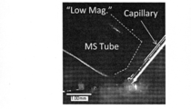
- Example 1 Observation with an ionizer using a high-speed camera The results of observation with a high-speed camera of a state where a liquid bridge is formed and a state where ions are generated using the method of the present invention are shown.
- FIGS. 6A and 6B show the probe, the substrate, and the ion intake unit (MS Tube) described in the chart of FIG.
- 6A and 6B are the results of observing the vicinity of liquid crosslinking at low magnification and high magnification, respectively.
- a silica capillary having an outer diameter of 150 micrometers and an inner diameter of 50 micrometers is used as a probe that is a means for providing a mixed solution, and is connected to a metal needle of a syringe, and a voltage connected to the metal needle. A voltage is applied through the applying device.
- the syringe is fixed to a syringe pump, and a constant flow rate of liquid can be delivered from the syringe to the probe tip.
- the vibration providing means is a piezoelectric element (PZT) having a resonance frequency of 28 kHz
- the substrate is a polytetrafluoroethylene film
- TSQ7000 Thermo Fisher Scientific
- FIG. 6A the distance between the tip of the probe and the MS tube was about 0.5 mm, and the distance between the MS tube and the substrate was about 0.5 mm.
- the angle between the probe of FIG. 6A and the substrate was about 50 degrees, and the angle between the probe of FIG. 6B and the substrate was about 25 degrees.
- the mixed solution flow rate was 0.2 microliters / minute.
- the MS tube was connected to the TSQ7000, and a potential of 37.5 V was applied to the connection portion, and the temperature was set to 250 degrees.
- FIG. 6B the liquid bridge formed between the lower part of the capillary and the substrate was clearly observed. It was also observed that the mixed solution formed a triangular shape at the top of the capillary tip, and a bright contrast region was present on the extension. This is the area where the Taylor cone and microdroplets are generated, respectively, and the mixed solution is electrostatically subjected to the force by the potential gradient between the potential provided to the mixed solution and the potential of the MS tube. It is considered to be a modified one. It is already known that the potential gradient is concentrated at the tip of the Taylor cone, and charged micro droplets are discharged (electrospray method). In this study, formation of a Taylor cone was observed when a voltage of 3 kV or higher was applied to the probe. In FIG. 6A, it was confirmed that similar Taylor cones and microdroplets were generated.
- Example 2 Verification of stable ionization method of insulin mixed solution The result when ionizing a biological component using the method of the present invention is shown.
- the flow rate of the mixed solution was set to 0.2 microliter / minute, and the measurement time was set to 5 minutes.
- a voltage of 3 kV or higher was applied to the probe, human insulin ions were detected.
- Other experimental conditions were the same as those presented in FIG. 6B of Example 1.
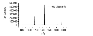
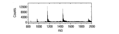
- FIG. 7A shows a mass spectrum of ions when vibration is provided to the substrate, and FIG. 7B shows a case where vibration is not provided.
- Each spectrum is integrated data for 5 minutes, the horizontal axis represents the mass-to-charge ratio (mass number / charge number), and the vertical axis represents the ion count number.
- peaks were observed at 1937, 1453, and 1163 m / z. These correspond to trivalent, tetravalent and pentavalent polyvalent ions, respectively, and it is considered that 3, 4, and 5 hydrogen ions were added to human insulin.
- the pentavalent ion intensity was highest, followed by a decrease in peak intensity in the order of tetravalent and trivalent peaks.
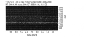
- FIG. 7C shows the change over time in ion intensity when vibration is applied to the substrate
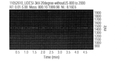
- FIG. 7D shows the change over time in ion intensity when vibration is stopped.
- the horizontal axis represents time
- the vertical axis represents the mass-to-charge ratio
- the amount of ions is shown in shades. That is, in FIG. 7C and FIG. 7D, it shows that the amount of ion is so large that it is displayed white.
- the amount of ions increases at locations corresponding to mass-to-charge ratios of 1937, 1453, and 1163.
- Example 3 Comparison with ESI
- BSA bovine serum albumin mixed solution
- the flow rate of each mixed solution was set to 0.2 microliter / minute, and measurement by this method and ESI method was performed.
- the measurement time of each method was 3 minutes, and the integrated spectra were compared.
- FIG. 8A and B show mass spectra of the human insulin mixed solution.
- FIG. 8A shows the result of this method
- FIG. 8B shows the result of the ESI method.
- the peak intensity at 1163 m / z is the largest, and the most pentavalent multivalent ions are generated. Comparing the intensity of this peak, it was found that 48 times or more ions were detected by using the ionization method of the present invention compared to the ESI method. This is because the distance from the ion generation point to the ion intake port is short, and both the effect of leading more ions to the mass spectrometer and the effect of increasing the amount of ions desorbed from the liquid bridge by vibrations. I believe that.
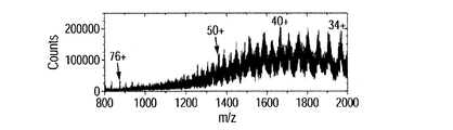
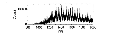
- FIGS. 8C, 8D, 8E, 8F, 8G, and 8H show mass spectra of the BSA mixed solution.
- FIG. 8C shows the result of this method
- FIG. 8D shows the result of the ESI method.
- multivalent ions of BSA were detected.
- the distribution of the peak intensity of multiply charged ions is different for each method.
- the intensity of 40 valent ions is the highest in this method
- the intensity of 48 valent ions is the highest in the ESI method. Comparing each ion intensity, it was found that the 40-valent ion intensity of the present method was about 1.6 times greater than the 48-valent ion of the ESI method.
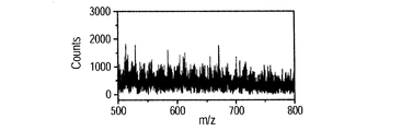
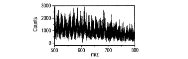
- FIGS. 8E, 8F, and 8G show mass spectra when a BSA mixed solution is used and voltages of 3 kV, 4 kV, and 5 kV are applied to the probe, respectively.
- Other experimental conditions are the same as those presented in FIG. 6B of Example 1.
- a plurality of peaks were detected in the region of 500 to 800 m / z, and the peak intensity increased as the applied voltage was increased.
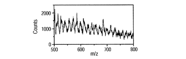
- FIG. 8H shows the result of smoothing processing (moving average of 10 adjacent points) on the spectrum data when 5 kV is applied. Compared with the spectrum of FIG. 8G, a peak was clearly recognized.
- peaks are thought to correspond to multivalent ions of BSA.
- a mechanism capable of imparting more charge than ESI is that cavitation is generated during liquid crosslinking by vibration, and more hydrogen ions are imparted by BSA. It is known that when cavitation occurs in a liquid, high-temperature and high-pressure bubbles are formed. Further, it is known that when a vibration is applied to a mixed solution in which a protein is dissolved, a higher-order structure of the protein is loosened. From this, it is considered that this method loosens the higher order structure of BSA existing in the liquid crosslinking and gives a lot of hydrogen ions to BSA.
- the present method may be able to detect multivalent ions that are difficult to detect by conventional ESI, for example, ions having a valence of 100 or more.
- Example 4 Verification of ionization method of solid insulin The result of examining the method of measuring the component distribution of the solid sample on the substrate is shown.
- the sample was prepared by dropping a human insulin aqueous solution (1 ⁇ M) onto a polytetrafluoroethylene substrate and air-drying it. It was confirmed that white solid crystallites covered the substrate.
- Other experimental conditions are the same as those presented in FIG. 6B of Example 1. While confirming with a microscope that the liquid bridge of the solvent is formed between the tip of the capillary and the substrate and that the Taylor cone is formed, the substrate is moved in a uniaxial direction to generate a mass of generated ions. The time change of the spectrum was measured.
- the frequency of the vibrator fixed on the back surface of the substrate was about 28 kHz, and after the vibration was generated 14000 times, the operation of stopping the vibration in the same time was alternately performed. From observation of high-speed camera and measurement of mass spectrum, liquid bridge is stably formed when vibration is stopped, and ions are stably generated when vibration is generated. It was confirmed.
- Fig. 9A shows the mass spectrum.
- peaks were observed at 1937, 1453, and 1163 m / z. These correspond to trivalent, tetravalent and pentavalent polyvalent ions, respectively, and it is considered that 3, 4, and 5 hydrogen ions were added to human insulin. From this result, it is considered that the solid sample on the substrate was dissolved in the solvent introduced from the capillary and then ionized via the Taylor cone. The distribution of each ion intensity in the spectrum was different from the distribution of peak intensity in Example 3 and Example 4, and the peak intensity decreased in the order of tetravalent, trivalent and pentavalent.
- FIG. 9B shows the time change of the intensity of each multivalent ion detected here.
- the time change of pentavalent, tetravalent, and trivalent ionic strength is shown in order from the top.
- ions were detected only in the period of 0.5 to 2.6 minutes, despite the presence of human insulin solid microcrystals on the entire surface of the substrate. This corresponds to a region where the vibration of the vibrator is generated, and is a result showing that the solid sample is stably ionized by providing vibration to the substrate.
- the substrate was moved in the uniaxial direction while confirming with a microscope that the liquid bridge of the solvent was formed between the tip of the capillary and the substrate, and that the Taylor cone was formed. At this time, adjustment was made so as to pass through all four ultrathin films on the substrate.
- Other experimental conditions are the same as those presented in FIG. 6B of Example 1.
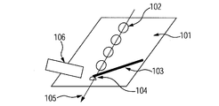
- FIG. 10A shows a diagram showing the moving direction of the sample and the substrate used in the experiment.
- 101 is a substrate
- 102 is an ultrathin film of BSA
- 103 is a capillary
- 104 is a liquid bridge
- 105 is an arrow indicating the moving direction of the substrate
- 106 is a cage for introducing ions into the mass spectrometer.
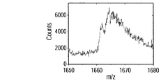
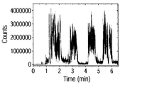
- 10C shows the time change of ions obtained in the region from 1660 to 1680. It was found that 40-valent ions were generated every time the liquid bridge passed through the four BSA thin films. This shows that the distribution of the components of the solid sample can be visualized by using this method.
- the above examples show the results when the vibration frequency is 28 kHz. However, the frequency is not limited to this, and the ion efficiency is better improved if the frequency is 100 Hz to 1 MHz.
- Example 6 Control of size of liquid bridge by vibration amplitude The result of examining the correlation between the amplitude of vibration given to the liquid bridge on the substrate and the size of the liquid bridge is shown.
- the solvent flow rate was 0.3 microliters / minute, and a voltage of 5 kV was applied to the probe.
- the frequency of the vibrator fixed to the back surface of the substrate was about 28 kHz, and the voltages input to the vibrator were 0V, 20V, and 30V (effective values).
- Other experimental conditions are the same as those presented in FIG.
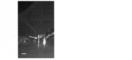
- FIGS. 11A, 11B, and 11C show observation results with a high-speed camera near the liquid bridge.
- 11A, 11B, and 11C in which station bridges are formed between the tip portion of the probe and the substrate, the input voltages correspond to 0V, 20V, and 30V, respectively.
- the scale bar is 100 micrometers. It can be seen that liquid crosslinks are formed at the arrows in each figure.
- Example 1 shows a thin contrast spray in which a diamond knife is incorporated and a method of cutting the capillary with a scriber.
- 11A, 11B, and 11C show the results when a capillary cut with a scraper is used.
- FIG. 6 shows an example when a capillary cut with a capillary cutter is used. It was confirmed that liquid bridge and Taylor cone were formed.
Abstract
The purpose of the present invention is to easily carry out soft ionization when ionizing a minutely small amount of a substance in an atmosphere environment. The present invention pertains to a method for ionizing a substance contained in a liquid, the ionization method being characterized by involving: a step for supplying a liquid from a probe to a substrate and for forming a liquid cross-link between the probe and the substrate by means of the liquid in which the substance is dissolved; a step for vibrating the substrate; and a step for forming an electric field between an ion extraction electrode and the conductive site of the probe with which the liquid is in contact.
Description
本発明は、物質のイオン化方法およびこれを用いた質量分析方法に関する。また、本発明は、物質の抽出方法、精製方法に関する。
The present invention relates to a substance ionization method and a mass spectrometry method using the same. The present invention also relates to a substance extraction method and a purification method.
成分分析法の一つである質量分析法は、試料中の成分をイオン化し、その質量電荷比(質量数/電荷数)を計測、分析する方法である。
Mass spectrometry, which is one of component analysis methods, is a method of ionizing components in a sample and measuring and analyzing the mass-to-charge ratio (mass number / charge number).
近年、固体試料表面に存在する成分の分布を画像化する技術が開発されている。特定の成分の分布を質量画像として可視化することで、試料の状況を判断することができる。このような技術の一例として、ガン組織を有する病理検体の質量画像を元に、病理診断の根拠となるデータを示す方法が開発されている。質量画像は、通常、複数の測定点で試料をイオン化し、発生したイオンの質量電荷比をそれぞれの測定点ごとに求め、試料表面の位置とイオンの情報を対応づけることにより取得する。そのため、得られる分析結果の空間分解能を向上するために、試料表面の微小領域をイオン化する技術が求められている。
In recent years, a technique for imaging the distribution of components existing on the surface of a solid sample has been developed. By visualizing the distribution of specific components as a mass image, the state of the sample can be determined. As an example of such a technique, a method has been developed that shows data as a basis for pathological diagnosis based on a mass image of a pathological specimen having cancer tissue. A mass image is usually obtained by ionizing a sample at a plurality of measurement points, obtaining a mass-to-charge ratio of the generated ions for each measurement point, and associating the position of the sample surface with ion information. Therefore, in order to improve the spatial resolution of the obtained analysis results, a technique for ionizing a minute region on the sample surface is required.
固体試料表面の微小領域に溶媒を付与して当該微小領域に存在する成分を溶解し、溶解した成分を大気圧環境下でイオン化する方法が提案されている(非特許文献1)。この方法では、固体試料中の成分を溶解するための溶媒を試料の表面に提供するための第一のキャピラリと、成分が溶媒に溶解した混合溶液をイオン化部分まで移動させるための第二のキャピラリとが用いられている。固体試料の表面に二本のキャピラリが近接した状態で、第一のキャピラリから溶媒が提供されることで、二本のキャピラリの先端部と試料表面との間に液架橋が形成される。この液架橋において固体試料の接触部分のみが溶解された後に、第二のキャピラリに導入される。溶媒には高電圧が印可されており、第二のキャピラリの先端部でイオン化される。この方法を用いることで、微小領域のイオン化が可能となる。また、大気圧環境下でイオン化をすることにより、計測時間の短縮化および装置の小型化が可能となり、数多くの試料の分析を行う際に有利である。
A method has been proposed in which a solvent is applied to a minute region on the surface of a solid sample to dissolve components present in the minute region, and the dissolved component is ionized under an atmospheric pressure environment (Non-Patent Document 1). In this method, a first capillary for providing a solvent for dissolving the components in the solid sample to the surface of the sample, and a second capillary for moving the mixed solution in which the components are dissolved in the solvent to the ionization portion And are used. By providing the solvent from the first capillary while the two capillaries are close to the surface of the solid sample, a liquid bridge is formed between the tips of the two capillaries and the sample surface. In this liquid bridge, only the contact portion of the solid sample is dissolved and then introduced into the second capillary. A high voltage is applied to the solvent and it is ionized at the tip of the second capillary. By using this method, it is possible to ionize a minute region. Further, by performing ionization under an atmospheric pressure environment, the measurement time can be shortened and the apparatus can be miniaturized, which is advantageous when many samples are analyzed.
また、試料が溶解した混合溶液に表面弾性波を照射することにより、含有する成分を大気圧環境下でイオン化する方法が提案されている(特許文献1)。この方法では、溶媒に試料が溶解している混合溶液を基板上に配置し、そこに表面弾性波を照射することで液体が霧化され、その後試料がイオン化される。さらに、特許文献1によれば、混合溶液に対して電圧を印可することで、イオン化効率を向上できると述べられている。
Also, a method has been proposed in which components contained therein are ionized under an atmospheric pressure environment by irradiating a surface acoustic wave to the mixed solution in which the sample is dissolved (Patent Document 1). In this method, a mixed solution in which a sample is dissolved in a solvent is placed on a substrate, and a liquid is atomized by irradiating a surface acoustic wave thereon, and then the sample is ionized. Furthermore, according to Patent Document 1, it is stated that ionization efficiency can be improved by applying a voltage to the mixed solution.
なお、生体組織などの生物由来の材料の質量分析において、生体成分を多価イオンとして検出する技術も求められている。検出対象となる成分の分子量が比較的大きい場合、多くの電荷を付与することで質量電荷比を小さくすることで、検出可能な質量電荷比が小さい検出器でも成分の検出が容易になる。
In addition, in mass spectrometry of biological materials such as biological tissues, a technique for detecting biological components as multivalent ions is also required. When the molecular weight of a component to be detected is relatively large, the detection of the component is facilitated even by a detector having a low detectable mass-to-charge ratio by reducing the mass-to-charge ratio by applying a large amount of charge.
非特許文献1に開示されている方法では、液架橋と固体試料の接触面積が、質量分析が実施される領域になるので、この面積を小さくするためには、液架橋を小さくする必要がある。しかしながら、この方法では、二本のキャピラリの先端部の最近接距離よりも小さなサイズの液架橋を作ることが困難であり、イオン化する領域を小さくすることによる空間分解能の向上が困難であるという課題がある。さらに、二本のキャピラリを物理的に近接させるためには、これらを精度良く合わせるための仕組みが別途必要になり、装置を構成する部品点数が増加し、装置自体も複雑なものになるという課題がある。
In the method disclosed in Non-Patent Document 1, since the contact area between the liquid bridge and the solid sample is a region where mass spectrometry is performed, it is necessary to reduce the liquid bridge in order to reduce this area. . However, with this method, it is difficult to make a liquid bridge having a size smaller than the closest distance between the tips of the two capillaries, and it is difficult to improve the spatial resolution by reducing the ionized region. There is. Furthermore, in order to physically bring the two capillaries close together, a mechanism for accurately aligning the two capillaries is required, which increases the number of parts constituting the device and complicates the device itself. There is.
特許文献1に開示されている方法は、被測定成分が事前に溶媒に溶解した混合溶液を測定対象としており、固体試料の一部をイオン化することは困難である。また、この方法では多価イオンの価数が従来のエレクトロスプレー法と比較して小さいという問題もある。
The method disclosed in Patent Document 1 uses a mixed solution in which a component to be measured is dissolved in a solvent in advance, and it is difficult to ionize a part of a solid sample. In addition, this method has a problem that the valence of multiply charged ions is smaller than that of the conventional electrospray method.
以上述べたように、大気圧環境下で固体の特定の領域から生体分子などの有機成分を多価イオンとして効率よく検出する方法はいずれの文献にも開示されていない。
As described above, none of the literature discloses a method for efficiently detecting an organic component such as a biomolecule as a polyvalent ion from a specific region of a solid under an atmospheric pressure environment.
本発明のイオン化方法は、液体に含まれる物質のイオン化方法であって、(1)プローブから基板上に液体を供給し、該プローブと該基板との間に該物質を含む液体による液架橋を形成する工程と、(2)前記基板を振動させる工程と、(3)前記液体が接する前記プローブの導電性部位とイオン引き出し電極の間で電界を形成する工程と、を有することを特徴とする。
The ionization method of the present invention is a method for ionizing a substance contained in a liquid. (1) A liquid is supplied from a probe onto a substrate, and liquid crosslinking with the liquid containing the substance is performed between the probe and the substrate. A step of forming, (2) a step of vibrating the substrate, and (3) a step of forming an electric field between a conductive portion of the probe in contact with the liquid and an ion extraction electrode. .
本発明によれば、液体に含まれる微小な量の物質を大気圧環境下で容易にイオン化することができるようになる。
According to the present invention, a minute amount of a substance contained in a liquid can be easily ionized under an atmospheric pressure environment.
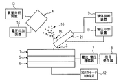
以下、本発明の方法について図面を示して説明する。本発明を実施する形態の一例を図1に示す。図1において、1は基板、2は液体が通過する流路を内部に有するプローブ、3は基板1とプローブ2の間に形成された液架橋、4は質量分析装置にイオンを取り込むためのイオン引き出し電極を有するイオン取込部、5は基板3を振動させる振動提供手段、6は振動提供手段5およびプローブ2を支持する試料ステージを示す。7は電流・電圧増幅器、8は信号発生器、9はプローブ2に液体を提供する液体供給装置、10は電圧印加装置、11は導電性の流路、12は試料ステージ制御器、13は質量分析装置、14は電圧印加装置、15はテイラーコーン、16は帯電した微小液滴である。
Hereinafter, the method of the present invention will be described with reference to the drawings. An example of an embodiment for carrying out the present invention is shown in FIG. In FIG. 1, 1 is a substrate, 2 is a probe having a flow path through which a liquid passes, 3 is a liquid bridge formed between the substrate 1 and the probe 2, and 4 is an ion for taking ions into the mass spectrometer. An ion take-in portion having an extraction electrode, 5 is a vibration providing means for vibrating the substrate 3, and 6 is a sample stage for supporting the vibration providing means 5 and the probe 2. 7 is a current / voltage amplifier, 8 is a signal generator, 9 is a liquid supply device for supplying a liquid to the probe 2, 10 is a voltage application device, 11 is a conductive channel, 12 is a sample stage controller, and 13 is a mass. An analysis device, 14 is a voltage application device, 15 is a Taylor cone, and 16 is a charged fine droplet.
本発明においては、まず、液体供給装置9から供給された液体が基板1とプローブ2との間で液架橋3を形成する。さらに、液架橋3が、振動提供手段5による基板1の振動と電圧印加装置10及び電圧印加装置14による電位勾配とによって、帯電した微小液滴16となることにより、測定対象の成分をイオンとしてイオン取込部4に取り込むことが可能となる。
すなわち、本形態においては、プローブが基板上への液体の付与手段であり、基板上の物質の取得手段であり、イオン化のための好適な位置への液体の移送手段であり、イオン化のためのテイラーコーンの形成手段となっている。 In the present invention, first, the liquid supplied from theliquid supply device 9 forms the liquid bridge 3 between the substrate 1 and the probe 2. Further, the liquid bridge 3 becomes a charged micro droplet 16 by the vibration of the substrate 1 by the vibration providing means 5 and the potential gradient by the voltage application device 10 and the voltage application device 14, so that the component to be measured is ionized. It becomes possible to take in the ion take-in part 4.
That is, in this embodiment, the probe is a means for applying a liquid onto the substrate, is a means for acquiring a substance on the substrate, is a means for transferring the liquid to a suitable position for ionization, and is used for ionization. It is a means of forming Taylor corn.
すなわち、本形態においては、プローブが基板上への液体の付与手段であり、基板上の物質の取得手段であり、イオン化のための好適な位置への液体の移送手段であり、イオン化のためのテイラーコーンの形成手段となっている。 In the present invention, first, the liquid supplied from the
That is, in this embodiment, the probe is a means for applying a liquid onto the substrate, is a means for acquiring a substance on the substrate, is a means for transferring the liquid to a suitable position for ionization, and is used for ionization. It is a means of forming Taylor corn.
液体供給装置9は、基板3上に固定された試料に含まれる被分析物を溶解するための溶媒又は被分析物と被分析物を溶解している溶媒との混合溶液(以下、これらの溶媒と混同溶液とをあわせて単に液体と記す)を供給する。液体供給装置9から供給された液体は、導電性の流路11を経由してプローブ2内部の流路へと導かれ、その際に、導電性の流路11を介して電圧印加装置10から液体に電圧が印加される。液体には直流電圧、交流電圧、パルス電圧又はゼロボルトのいずれかが印加される。
The liquid supply device 9 is a solvent for dissolving the analyte contained in the sample fixed on the substrate 3 or a mixed solution of the analyte and the solvent dissolving the analyte (hereinafter referred to as these solvents). And the confusion solution are simply referred to as liquid). The liquid supplied from the liquid supply device 9 is guided to the flow channel inside the probe 2 via the conductive flow channel 11, and at that time, from the voltage application device 10 via the conductive flow channel 11. A voltage is applied to the liquid. Either DC voltage, AC voltage, pulse voltage, or zero volts is applied to the liquid.
なお、本実施形態において、プローブとは、プローブ2の内部の流路や接続用配管に導電性の流路11の全部又は一部分が包摂されている場合は、これらの総称を意味する。また、プローブ2の内部の流路や接続用配管に導電性の流路11が包摂されていない場合にも、本実施形態におけるプローブは、広義には、これらの総称を意味する。すなわち、プローブを形成する素材の少なくとも一部分が導電性であればよい。導電性を有する材料には、金属・半導体などが挙げられるが、電圧印加装置から電圧が印加された場合に、再現性のある一定の電圧値を示す性質を有するものであればいかなるものでもよい。つまり、本実施形態において、プローブの導電性部位に電圧を印加することで、液体に電圧を印加している。
In addition, in this embodiment, a probe means these generic names, when the whole or a part of the electroconductive flow path 11 is included in the flow path inside the probe 2, or connection piping. Further, even when the conductive flow path 11 is not included in the flow path inside the probe 2 or the connection pipe, the probe in the present embodiment is a general term for these. That is, it is sufficient that at least a part of the material forming the probe is conductive. Examples of the conductive material include metals and semiconductors, and any material may be used as long as it has a property of showing a reproducible and constant voltage value when a voltage is applied from a voltage application device. . That is, in this embodiment, the voltage is applied to the liquid by applying a voltage to the conductive portion of the probe.
本実施形態でプローブに電圧を印加するとは、後述のイオン引き出し電極の電位とは異なる電位を、プローブの少なくとも一部分を形成する導電性部位に付与し、プローブの少なくとも一部分を形成する導電性部位と後述のイオン引き出し電極の間で、電界を形成することを意味する。この電界が達成される限りにおいて、ここで印加される電圧がゼロボルトであってもよい。流路11の材料は導電性の物質であれば良く、例えばステンレス・金・白金などを用いることができる。
Applying a voltage to the probe in this embodiment means that a potential different from the potential of an ion extraction electrode described later is applied to a conductive portion that forms at least a portion of the probe, and a conductive portion that forms at least a portion of the probe It means that an electric field is formed between ion extraction electrodes described later. As long as this electric field is achieved, the voltage applied here may be zero volts. The material of the flow path 11 may be a conductive substance, and for example, stainless steel, gold, platinum, or the like can be used.
プローブ2、導電性の流路11及び液体供給装置9を接続する接続用配管としては、例えば、シリカキャピラリやメタルキャピラリ等の細管などの、微小体積の液体を供給する細管を利用することでき、その電気伝導性は絶縁体・導電体・半導体のいずれであってもよい。なお、導電性の流路11は、液体供給装置9から供給された液体がプローブ2内部を通り、液体供給装置9とは反対側のプローブ2の先端まで導かれる流路の一部分を構成すればよく、その位置は特に限定されない。例えば、プローブ2の内部の流路や接続用配管に導電性の流路11の全部又は一部分が包摂されていても良く、このような構成として、ステンレス線、タングステン線、白金線などの導電性物体がシリカキャピラリに挿入されたプローブなどを用いることができる。
As a connection pipe for connecting the probe 2, the conductive channel 11 and the liquid supply device 9, for example, a thin tube for supplying a small volume of liquid, such as a thin tube such as a silica capillary or a metal capillary, can be used. The electrical conductivity may be any of an insulator, a conductor, and a semiconductor. The conductive flow path 11 may be a part of a flow path in which the liquid supplied from the liquid supply device 9 passes through the probe 2 and is led to the tip of the probe 2 on the side opposite to the liquid supply device 9. Well, the position is not particularly limited. For example, all or a part of the conductive flow path 11 may be included in the flow path inside the probe 2 or the connection pipe. As such a configuration, a conductive material such as a stainless steel wire, a tungsten wire, or a platinum wire is used. A probe or the like in which an object is inserted into a silica capillary can be used.
プローブ2そのものが導電体の場合、導電性の流路11に印加された電圧がプローブ2に伝播し、プローブ2内部の流路の液体に電圧が印加される。このような実施形態の詳細は、本明細書の第二の実施形態に記載されている。一方、プローブ2が絶縁体の場合、導電性の流路11に印加された電圧はプローブ2に伝播することができないが、流路11に流れる液体に電圧が印加され、その液体がプローブ2に導入されるため、プローブ2に電圧が伝播されていない場合にも、液体に電圧を印加し、液体を帯電させることになる。
When the probe 2 itself is a conductor, the voltage applied to the conductive channel 11 propagates to the probe 2 and the voltage is applied to the liquid in the channel inside the probe 2. Details of such an embodiment are described in the second embodiment herein. On the other hand, when the probe 2 is an insulator, the voltage applied to the conductive channel 11 cannot propagate to the probe 2, but the voltage is applied to the liquid flowing in the channel 11, and the liquid is applied to the probe 2. Therefore, even when no voltage is propagated to the probe 2, the voltage is applied to the liquid to charge the liquid.
液体供給装置9から供給された液体は、プローブ2の先端から基板1上へと提供される。このとき、試料を基板上にあらかじめ固定化しておき、基板1上の試料に含まれる被分析物としての特定の成分をプローブ2から提供された溶媒に溶解させてもよいし、あらかじめ被分析物が溶媒と混合された混合溶液を基板1上に提供してもよい。また、複数の種類の液体を用いてもよい。
The liquid supplied from the liquid supply device 9 is provided from the tip of the probe 2 onto the substrate 1. At this time, the sample may be immobilized on the substrate in advance, and a specific component as the analyte contained in the sample on the substrate 1 may be dissolved in the solvent provided from the probe 2, A mixed solution in which is mixed with a solvent may be provided on the substrate 1. A plurality of types of liquids may be used.
本発明は、プローブ2と基板1とが液体を介してつながった状態で基板1に振動を付与し、さらにプローブ2とイオン引き出し電極との間で電界を形成して、物質をイオン化させる工程を有する。2つの物体が液体を介してつながった状態は、一般に液架橋と呼ばれる。本実施形態において、液架橋3とは、プローブ2から提供された液体が、少なくとも、プローブ2及び基板1の両方に物理的に接触している状態のことをいう。なお、本発明の液架橋は基板1及びプローブ2のみに接触している状態に限られるものではなく、液架橋に基板1及びプローブ2以外の物体が接触していても構わない。プローブ2から提供される液体は、連続的または断続的に基板1上に提供される。プローブ2は必ずしも基板1に接触する必要はないが、液架橋3を安定して形成するためには接触していても構わない。
The present invention includes a step of ionizing a substance by applying vibration to the substrate 1 in a state where the probe 2 and the substrate 1 are connected via a liquid, and further forming an electric field between the probe 2 and the ion extraction electrode. Have. A state in which two objects are connected via a liquid is generally called liquid bridge. In the present embodiment, the liquid bridge 3 refers to a state in which the liquid provided from the probe 2 is in physical contact with at least both the probe 2 and the substrate 1. The liquid bridge of the present invention is not limited to the state in which only the substrate 1 and the probe 2 are in contact, and an object other than the substrate 1 and the probe 2 may be in contact with the liquid bridge. The liquid provided from the probe 2 is provided on the substrate 1 continuously or intermittently. The probe 2 is not necessarily in contact with the substrate 1 but may be in contact with the substrate 2 in order to stably form the liquid bridge 3.
すなわち、(1)プローブから基板上に液体を供給し、該プローブと該基板との間に該物質を含む液体による液架橋を形成する工程と、(2)前記基板を振動させる工程と、
(3)前記液体が接する前記プローブの導電性部位とイオン引き出し電極の間で電界を形成する工程と、を有する。
そして、(1)工程、(2)工程および(3)工程を、簡便な構成で同時に行うことができる。 (1) supplying a liquid from the probe onto the substrate and forming a liquid bridge with the liquid containing the substance between the probe and the substrate; (2) vibrating the substrate;
(3) forming an electric field between the conductive portion of the probe in contact with the liquid and the ion extraction electrode.
And (1) process, (2) process, and (3) process can be performed simultaneously with a simple structure.
図1では、基板1は振動提供手段5に支持されており、振動提供手段5から基板1に振動が提供される。図1には、基板1が振動提供手段5に固定化されている状態が示されているが、基板1が振動可能であり、振動することで液架橋4に振動を提供することができれば、基板1と振動提供手段5が離れていてもよい。
In FIG. 1, the substrate 1 is supported by the vibration providing means 5, and vibration is provided from the vibration providing means 5 to the substrate 1. FIG. 1 shows a state in which the substrate 1 is fixed to the vibration providing means 5, but if the substrate 1 can vibrate and can provide vibration to the liquid bridge 4 by vibration, The substrate 1 and the vibration providing means 5 may be separated.
基板1の振動は、連続的振動・断続的振動のいずれであってもよい。流路11を通じて電圧を印加された液体が液架橋3を形成しているときに基板1が振動するよう、液体に電圧を印加するタイミングと基板1を振動させるタイミングを調整することが望ましい。振動提供装置は電流・電圧増幅器7及び信号発生装置8と電気的に接続されており、信号発生装置8で生成した任意の波形の信号を電流・電圧増幅器7に入力することで、高電圧の信号を生成することができる。その際、電流・電圧増幅器7から出力される電圧値を変更することにより、振動の振幅を任意の値にすることができる。
The vibration of the substrate 1 may be either continuous vibration or intermittent vibration. It is desirable to adjust the timing at which the voltage is applied to the liquid and the timing at which the substrate 1 is vibrated so that the substrate 1 vibrates when the liquid to which the voltage is applied through the flow path 11 forms the liquid bridge 3. The vibration providing device is electrically connected to the current / voltage amplifier 7 and the signal generator 8. By inputting a signal having an arbitrary waveform generated by the signal generator 8 to the current / voltage amplifier 7, A signal can be generated. At that time, by changing the voltage value output from the current / voltage amplifier 7, the amplitude of vibration can be set to an arbitrary value.
また、振動は、常に提供してもよいし、振動状態及び非振動状態が交互に生じてもよい。振動状態および非振動状態が交互に生じる場合は、それぞれの状態の長さを任意に変更することができる。ただし、プローブ2から基板1上に断続的に液体を提供する場合は、液架橋を形成した液体に振動が伝わるように振動状態及び非振動状態の長さを変更することが望ましい。
Further, vibration may be always provided, or a vibration state and a non-vibration state may occur alternately. When the vibration state and the non-vibration state occur alternately, the length of each state can be arbitrarily changed. However, when the liquid is intermittently provided on the substrate 1 from the probe 2, it is desirable to change the length of the vibration state and the non-vibration state so that vibration is transmitted to the liquid in which the liquid bridge is formed.
液架橋3を形成する液体は、振動され、さらに、電圧が印可されたプローブと電圧印加装置14により電圧が印加されるイオン引き出し電極との間の電位勾配により、プローブ2のイオン取込部4側の側面に移動し、テイラーコーン15を形成する。テイラーコーン15の先端部分では電位勾配が大きくなり、混合溶液から微小な帯電液滴16が発生する。電位勾配の大きさを適当に設定することで、レイリー分裂が生じ、帯電液滴16から特定の成分のイオンが発生し、気流の流れと電位勾配に従ってイオン取込部4へと導かれる。イオン取込部4は室温から数百度の間の特定の温度に加熱され、電圧が印加され、さらに排気用ポンプと接続されている。このとき、レイリー分裂が生じイオンが発生するように適切な電位勾配が生じるように、電圧印加装置10からプローブに印加される電圧と電圧印加装置14によりイオン引き出し電極に印加される電圧を調整する必要がある。電圧印加装置14からの電圧としては、直流電圧・交流電圧・パルス電圧・ゼロボルトのいずれかもしくはそれらの組み合わせを用いることができる。なお、レイリー分裂が生じるための電位勾配は、プローブに印加した電位と、イオン取込部4の電位と、液体とイオン取込部4との距離により規定される。そのため、イオン化したい物質や溶媒の種類に従って、適切な電位勾配が生じるように、これらを設定する必要がある。ここで、レイリー分裂とは帯電液滴6がレイリー極限に達し、帯電液滴中の過剰な電荷が、二次液滴として放出される現象のことをいう。レイリー分裂が生じている間に、帯電液滴6に含まれる成分が気相イオンとして発生することが知られている。(J.Mass Spectrom. Soc. Jpn.Vol.58、139-154、2010)
The liquid forming the liquid bridge 3 is vibrated, and further, due to a potential gradient between the probe to which the voltage is applied and the ion extraction electrode to which the voltage is applied by the voltage application device 14, the ion intake section 4 of the probe 2. It moves to the side surface and forms the Taylor cone 15. The potential gradient increases at the tip of the Taylor cone 15, and minute charged droplets 16 are generated from the mixed solution. By appropriately setting the magnitude of the potential gradient, Rayleigh splitting occurs, ions of a specific component are generated from the charged droplets 16, and are guided to the ion take-in unit 4 according to the flow of the air current and the potential gradient. The ion take-in unit 4 is heated to a specific temperature between room temperature and several hundred degrees, a voltage is applied, and it is further connected to an exhaust pump. At this time, the voltage applied from the voltage application device 10 to the probe and the voltage applied to the ion extraction electrode by the voltage application device 14 are adjusted so that an appropriate potential gradient is generated so that Rayleigh splitting occurs and ions are generated. There is a need. As the voltage from the voltage application device 14, any one of a DC voltage, an AC voltage, a pulse voltage, zero volts, or a combination thereof can be used. Note that the potential gradient for causing Rayleigh splitting is defined by the potential applied to the probe, the potential of the ion capturing unit 4, and the distance between the liquid and the ion capturing unit 4. Therefore, it is necessary to set these so that an appropriate potential gradient is generated according to the type of the substance or solvent to be ionized. Here, Rayleigh splitting refers to a phenomenon in which the charged droplet 6 reaches the Rayleigh limit and excessive charges in the charged droplet are released as secondary droplets. It is known that components contained in the charged droplet 6 are generated as gas phase ions during Rayleigh splitting. (J. Mass Spectrom. Soc. Jpn. Vol. 58, 139-154, 2010)
イオン取込部4とプローブ2、イオン取込部4と基板1の距離はそれぞれ任意に変更することができるが、テイラーコーンを安定に形成することができるための条件を満たすことが好ましい。また、プローブ2の基板1に対する角度は0度以上90度以下、イオン取込部4の基板1に対する角度は0度以上90度以下であることが望ましい。ここでプローブ2の基板1に対する角度とは、プローブ2の線分を含む平面が基板1に対して直交する場合に、この平面と基板1の交線とプローブ2の線分がなす角の大きさのことをいい、イオン取込部4の基板1に対する角度とは、イオン取込部4の線分を含む平面が基板1に対して直交する場合に、この平面と基板1の交線とイオン取込部4の線分がなす角の大きさのことをいう。キャピラリの線分とはキャピラリの長軸に並行な線分であり、イオン取込部4の線分とはイオン取込部4がイオンを取り込む方向の軸に並行な線分である。プローブ2およびイオン取込部4は必ずしも直線である必要ななく、曲線の形状を有しても構わないが、この場合の線分はプローブ2が基板に近接している先端部分、イオン取込部4が基板に近接している先端部分の、直線であると近似できる部分を線分とすることとする。本発明者の検討によれば、プローブ2の角度は20度から40度、イオン取込部4の角度は30度から50度が適切であったが、この大きさに限定されるものではなく、テイラーコーンがキャピラリ先端部分で安定して形成される条件であれば、イオンは安定して発生すると考えられる。
The distances between the ion take-in unit 4 and the probe 2 and between the ion take-in unit 4 and the substrate 1 can be arbitrarily changed, but it is preferable to satisfy the conditions for stably forming the Taylor cone. Further, it is desirable that the angle of the probe 2 with respect to the substrate 1 is 0 degree or more and 90 degrees or less, and the angle of the ion capturing part 4 with respect to the substrate 1 is 0 degree or more and 90 degrees or less. Here, the angle of the probe 2 with respect to the substrate 1 is a large angle formed by the intersection of the plane and the substrate 1 and the line segment of the probe 2 when the plane including the line segment of the probe 2 is orthogonal to the substrate 1. That is, the angle of the ion intake 4 with respect to the substrate 1 is the intersection of the plane and the substrate 1 when the plane including the line segment of the ion intake 4 is orthogonal to the substrate 1. It means the size of the angle formed by the line segment of the ion take-in part 4. The line segment of the capillary is a line segment parallel to the long axis of the capillary, and the line segment of the ion capturing unit 4 is a line segment parallel to the axis in the direction in which the ion capturing unit 4 captures ions. The probe 2 and the ion take-in portion 4 do not necessarily have to be a straight line and may have a curved shape. In this case, the line segment is the tip portion where the probe 2 is close to the substrate, the ion take-in A portion that can be approximated as a straight line at the tip portion where the portion 4 is close to the substrate is defined as a line segment. According to the study of the present inventor, the angle of the probe 2 is 20 to 40 degrees and the angle of the ion capturing part 4 is 30 to 50 degrees, but it is not limited to this size. If the conditions are such that the Taylor cone is stably formed at the tip of the capillary, ions are considered to be generated stably.
その後、イオンはイオン取込部4と接続されている質量分析手段へ差動排気系を通じて導入され、イオンの質量電荷比が計測される。質量分析装置には四重極型質量分析計、飛行時間型質量分析計、磁場偏向型質量分析計、イオントラップ型質量分析計、イオンサイクロトロン型質量分析計などを利用することができる。また、イオンの質量電荷比(質量数/電荷数、以下m/zと記す)とイオンの発生量の相関を計測することで、質量スペクトルを得ることもできる。
Thereafter, the ions are introduced into the mass analysis means connected to the ion take-in unit 4 through the differential exhaust system, and the mass-to-charge ratio of the ions is measured. As the mass spectrometer, a quadrupole mass spectrometer, a time-of-flight mass spectrometer, a magnetic field deflection mass spectrometer, an ion trap mass spectrometer, an ion cyclotron mass spectrometer, or the like can be used. A mass spectrum can also be obtained by measuring the correlation between the mass-to-charge ratio of ions (mass number / charge number, hereinafter referred to as m / z) and the amount of ions generated.
テイラーコーン15のサイズは液体の流量、液体の組成、プローブ2の形状、基板1の振動、電位勾配の大きさなどにより変化する。テイラーコーン15が非常に小さい場合、その形態は顕微鏡などで確認されない場合があるが、イオンが安定的に発生していればよい。
The size of the Taylor cone 15 varies depending on the flow rate of the liquid, the composition of the liquid, the shape of the probe 2, the vibration of the substrate 1, the magnitude of the potential gradient, and the like. When the Taylor cone 15 is very small, its form may not be confirmed by a microscope or the like, but it is sufficient that ions are stably generated.
本実施形態においては、液体の流量や基板1の振動を制御して液架橋3の形成時間を調整することで、液架橋4を構成する液体の容量を容易に制御することができる。そのため、あらかじめ被分析物が溶媒と混合された混合溶液をプローブから提供する際は、イオン化する被分析物の量を微細に調節することができる。また、基板1上に試料を固定してプローブから提供する溶媒に溶解するときも、液架橋3の形成時間を調整することで、液架橋3が接する領域を小さくして、微小領域の成分のみをイオン化することが可能になるので、細胞等の生体物質の解像度の高い質量分析イメージングが可能となる。
In this embodiment, the volume of the liquid constituting the liquid bridge 4 can be easily controlled by adjusting the formation time of the liquid bridge 3 by controlling the flow rate of the liquid and the vibration of the substrate 1. Therefore, when providing a mixed solution in which the analyte is mixed with the solvent in advance from the probe, the amount of the analyte to be ionized can be finely adjusted. In addition, when the sample is fixed on the substrate 1 and dissolved in the solvent provided from the probe, by adjusting the formation time of the liquid bridge 3, the area where the liquid bridge 3 is in contact is reduced, so that only the components in the micro area are obtained. Can be ionized, so that mass spectrometry imaging with high resolution of biological materials such as cells can be performed.
また、基板上に試料を固定してイオン化する場合、試料ステージ制御装置12により基板ステージ6の位置を変化させることにより、試料のうちイオン化される位置の座標を制御することができる。イオン化された位置の座標と、得られた質量スペクトルとを対応付けることで、質量スペクトルの二次元分布を得ることができる。この方法で得られるデータは、イオン化された位置の座標(X座標およびY座標)及び質量スペクトルにより構成される3次元データとなる。異なる位置でイオン化及び質量スペクトルの取得を行った後に、任意の質量電荷比のイオン量を選択し、その分布を表示することで、成分ごとの質量イメージを得ることができ、試料表面の特定の成分の分布を捉えることもできる。試料の移動方法は、プローブ2により形成される液架橋3が測定したい任意の平面内を走査するように設定すればよい。
When the sample is fixed on the substrate and ionized, the position of the substrate stage 6 is changed by the sample stage control device 12 so that the coordinates of the ionized position in the sample can be controlled. By associating the coordinates of the ionized position with the obtained mass spectrum, a two-dimensional distribution of the mass spectrum can be obtained. Data obtained by this method is three-dimensional data composed of coordinates (X coordinate and Y coordinate) of ionized positions and a mass spectrum. After performing ionization and acquisition of mass spectra at different positions, selecting an ion amount with an arbitrary mass-to-charge ratio and displaying its distribution makes it possible to obtain a mass image for each component, and a specific surface of the sample. The distribution of components can also be captured. The sample moving method may be set so that the liquid bridge 3 formed by the probe 2 scans in an arbitrary plane to be measured.
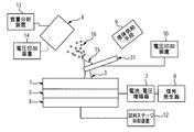
本発明の第二の実施形態において、図2に示すように、液体が通過する流路を内部に有するプローブを介して液架橋に電圧を印加しても良い。このとき、プローブ21は電圧印加装置10と電気的に接続されており、液体供給装置9から供給される液体にプローブ21を介して電圧が印加される。なお、上述の実施形態と同様に、プローブに電圧を印加するとは、イオン引き出し電極による電位とは異なる電位をプローブの少なくとも一部分を形成する導電性部位に付与して、レイリー分裂によるイオンの発生が可能な電界を、イオン引き出し電極とプローブの間に形成することを意味し、この電界が達成される限りにおいて、ここでプローブの少なくとも一部分を形成する導電性部位に印加される電圧がゼロボルトであってもよい。プローブ21の材料は導電性の物質であれば良く、例えばステンレス・金・白金などの金属、または金属が一部分を被覆しているガラスなどの誘電体を用いることができる。
In the second embodiment of the present invention, as shown in FIG. 2, a voltage may be applied to the liquid bridge via a probe having a flow path through which the liquid passes. At this time, the probe 21 is electrically connected to the voltage application device 10, and a voltage is applied to the liquid supplied from the liquid supply device 9 via the probe 21. As in the above-described embodiment, applying a voltage to the probe means that a potential different from the potential due to the ion extraction electrode is applied to a conductive portion that forms at least a part of the probe, and the generation of ions due to Rayleigh splitting occurs. This means that a possible electric field is formed between the ion extraction electrode and the probe, and as long as this electric field is achieved, the voltage applied to the conductive sites forming at least a portion of the probe is zero volts. May be. The material of the probe 21 may be a conductive substance, and for example, a metal such as stainless steel, gold, or platinum, or a dielectric material such as glass with a metal partially covered can be used.
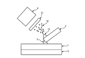
また、本発明の第三の実施形態において、図3に示すように、プローブは液体が通過する流路を内部に有する必要はなく、液体供給手段9からの液体をプローブ表面に提供し、プローブ表面の一部分でイオンを発生させても良い。この形態において、液体供給手段9からは、インクジェット法、エレクトロスプレー法、エアジェット式スプレー法、滴下法などによりプローブ31の一部分に液体を提供し、液架橋3及びテイラーコーン15を形成することができる。なお、図3に示すようにプローブを電極としてプローブから液体電圧を印加してもよいし、図1のようにプローブに液体を提供する前に液体に電圧を印加してもよい。
In the third embodiment of the present invention, as shown in FIG. 3, the probe does not have to have a flow path through which the liquid passes, and the liquid from the liquid supply means 9 is provided on the probe surface, Ions may be generated on a part of the surface. In this embodiment, the liquid supply means 9 can provide a liquid to a part of the probe 31 by an ink jet method, an electrospray method, an air jet spray method, a dropping method or the like, thereby forming the liquid bridge 3 and the Taylor cone 15. it can. As shown in FIG. 3, a liquid voltage may be applied from the probe using the probe as an electrode, or a voltage may be applied to the liquid before providing the liquid to the probe as shown in FIG.
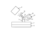
また、本発明の第四の実施形態において、図4に示すように、複数の種類の液体を供給することができるプローブを用いても良い。図4において、プローブ41は、液体を供給する第一の流路42及び液体を供給する第二の流路43を有する。第一の流路42と基板1との間には液架橋3が形成される。一方で、第二の流路43の先端部は試料と接触しないように振動の振幅やプローブの角度を調整することで、第二の流路43から出た液体は液架橋を形成しないようにできる。なお、この時、流路42を流れる第一の液体及び流路43を流れる第二の液体には、それぞれ異なる導電性の流路を通じて、異なる電位を独立して与えることもできる。
In the fourth embodiment of the present invention, as shown in FIG. 4, a probe capable of supplying a plurality of types of liquids may be used. In FIG. 4, the probe 41 has a first flow path 42 for supplying a liquid and a second flow path 43 for supplying a liquid. A liquid bridge 3 is formed between the first flow path 42 and the substrate 1. On the other hand, by adjusting the amplitude of vibration and the angle of the probe so that the tip of the second channel 43 does not come into contact with the sample, the liquid exiting the second channel 43 does not form a liquid bridge. it can. At this time, different potentials can be independently applied to the first liquid flowing in the flow path 42 and the second liquid flowing in the flow path 43 through different conductive flow paths.
液体を供給する第一の流路42及び液体を供給する第二の流路43には、別種類の液体を流してもよいし、同一種類の液体を流してもよい。例えば、別種類の液体を用いる場合、試料表面の成分を溶解する溶媒を第一の流路42に導入し、特定の成分と反応する分子種を含む溶媒を第二の流路43に導入することで、特定の成分を選択的にイオン化させることができる。
In the first flow path 42 for supplying the liquid and the second flow path 43 for supplying the liquid, another type of liquid may be supplied or the same type of liquid may be supplied. For example, when another type of liquid is used, a solvent that dissolves the component on the sample surface is introduced into the first flow path 42, and a solvent that includes a molecular species that reacts with a specific component is introduced into the second flow path 43. Thus, a specific component can be selectively ionized.
また、同一の液体を用いる場合、例えば、試料表面と接触し、液架橋を形成するための液体を第一の流路42及び第二の流路43に導入する。このとき、プローブ41の側面が第二の流路43から出た液体で常に洗浄されることにより、プローブ先端部分の側面の汚染を防ぎ、質量イメージの空間分解能の低下を防ぐことができる。
なお、ここで示したのは一例であり、上記流路の空間的な位置関係が異なっていても、3種類以上の流路を内包するプローブを用いても良い。 When the same liquid is used, for example, a liquid for forming a liquid bridge in contact with the sample surface is introduced into thefirst channel 42 and the second channel 43. At this time, the side surface of the probe 41 is always washed with the liquid discharged from the second flow path 43, whereby contamination of the side surface of the probe tip portion can be prevented and a reduction in the spatial resolution of the mass image can be prevented.
In addition, what was shown here is an example, and even if the spatial positional relationship of the said flow path differs, the probe which includes three or more types of flow paths may be used.
なお、ここで示したのは一例であり、上記流路の空間的な位置関係が異なっていても、3種類以上の流路を内包するプローブを用いても良い。 When the same liquid is used, for example, a liquid for forming a liquid bridge in contact with the sample surface is introduced into the
In addition, what was shown here is an example, and even if the spatial positional relationship of the said flow path differs, the probe which includes three or more types of flow paths may be used.
また、上記実施形態において、成分のイオン化に必要な電位勾配は、プローブに印加した電位と、イオン取込部4の電位と、液体とイオン取込部4の距離により調節しているが、本発明はこれに限られるものではない。本発明の第五の実施形態において、図5に示すように、液体の周囲に電位勾配を形成するための機構51を設けることもできる。本実施形態では、液架橋3に印加された電圧及び電極51に印加された電圧並びに液架橋3と電極51の距離により規定される電位勾配を、液体に含まれる成分のイオン化に用いる。電極51の形状はリング状、メッシュ状、ドット状・ロッド状などを用いることができる。
In the above-described embodiment, the potential gradient necessary for ionization of the component is adjusted by the potential applied to the probe, the potential of the ion capturing unit 4, and the distance between the liquid and the ion capturing unit 4. The invention is not limited to this. In the fifth embodiment of the present invention, as shown in FIG. 5, a mechanism 51 for forming a potential gradient around the liquid may be provided. In the present embodiment, a voltage gradient defined by a voltage applied to the liquid bridge 3, a voltage applied to the electrode 51, and a distance between the liquid bridge 3 and the electrode 51 is used for ionization of components contained in the liquid. The electrode 51 may have a ring shape, a mesh shape, a dot shape, a rod shape, or the like.
本実施形態においてイオン化の対象となる試料は、特に限定されることはない。脂質・糖・蛋白質などの高分子からなる有機化合物をイオン化の対象とする際には、本実施形態の方法によれば、これらの物質を容易にソフトイオン化することが可能となる。
また、本発明によれば、特に有機物を含有する試料中の成分を多価イオンに変換することができる。大きな分子量を有する生体成分に対して、価数の大きな多価イオンを形成することができると、計測可能な質量電荷比が小さい質量分析装置でも、生体成分を検出することができるようになるため、計測に関わるコストを削減できる。 In the present embodiment, the sample to be ionized is not particularly limited. When organic compounds composed of macromolecules such as lipids, sugars, and proteins are targeted for ionization, according to the method of this embodiment, these substances can be easily soft ionized.
Moreover, according to the present invention, it is possible to convert a component in a sample containing an organic substance into a multivalent ion. If multivalent ions with a large valence can be formed for a biological component having a large molecular weight, the biological component can be detected even with a mass spectrometer having a small measurable mass-to-charge ratio. , The cost related to measurement can be reduced.
また、イオンはそれぞれ固有の質量電荷比を有しているので、外部の電位勾配の強度を調整すれば、特定のイオンのみを分離することができる。すなわち、混合物中の特定の成分を抽出・精製することができる。例えば、培養細胞の破砕抽出物に含まれる複数の成分のうち、生体の特定の部位に親和性を有するタンパク質などのみを分離することができ、分離された特定の成分をある物質の表面に付与すれば、その成分の機能をその物質に付加することも可能になる。また、特定の疾患部位に特異的に反応する成分を薬剤表面に付与すれば、薬効を向上する効果が期待される。また、本発明の方法で分離・精製したタンパク質などの物質を、人工臓器などの生体内で使用される物体の表面に付与すれば、生体内での拒絶反応を抑制する効果も期待される。
Also, since each ion has a specific mass-to-charge ratio, only specific ions can be separated by adjusting the strength of the external potential gradient. That is, a specific component in the mixture can be extracted and purified. For example, it is possible to separate only a protein having affinity for a specific part of a living body from among a plurality of components contained in a crushed extract of cultured cells, and apply the separated specific component to the surface of a certain substance Then, the function of the component can be added to the substance. Moreover, if the component which reacts specifically with a specific disease site | part is provided to the chemical | medical agent surface, the effect which improves a pharmaceutical effect is anticipated. In addition, if a substance such as protein separated and purified by the method of the present invention is applied to the surface of an object used in a living body such as an artificial organ, an effect of suppressing rejection in the living body is expected.
特定の成分のみを分離する方法の一例として、複数のイオン種を真空チャンバ内に導入し、電位勾配による分離を行った後に、特定のイオン成分のみを真空チャンバ内の基板に集積する方法が挙げられる。この方法を用いれば、前記成分が集積された基板を真空チャンバから取り出し、適切な溶媒を用いて基板から当該成分を分離することができる。また、真空チャンバ内に人工臓器などの物体を設置し、分離されたイオンを直接付与する方法もある。
As an example of a method for separating only specific components, there is a method in which a plurality of ion species are introduced into a vacuum chamber, and after separation by a potential gradient, only specific ion components are accumulated on a substrate in the vacuum chamber. It is done. By using this method, the substrate on which the components are accumulated can be taken out of the vacuum chamber, and the components can be separated from the substrate using an appropriate solvent. There is also a method in which an object such as an artificial organ is placed in a vacuum chamber and the separated ions are directly applied.
また、プローブ(液体供給手段)の一部分に突起物を設けることで、突起物に沿ってテイラーコーンが形成され、より安定してイオンを発生させることが可能になる。
Also, by providing a protrusion on a part of the probe (liquid supply means), a Taylor cone is formed along the protrusion, and ions can be generated more stably.
また、振動の周波数を100Hz以上1MHz以下にすれば、さらに多くの電荷を成分に付与し、イオン化できるようになり、タンパク質などの大きな分子量の成分に多くの電荷を与えることで、低い電荷質量比でも成分を検出することができるようになる。さらに、振動を液架橋に付与することで、液架橋の体積を任意の状態に変更することができるようになり、液架橋の大きさを制御できるようになる。
In addition, if the frequency of vibration is set to 100 Hz or more and 1 MHz or less, more charge can be imparted to the component and ionization can be performed. But it will be possible to detect the components. Furthermore, by applying vibration to liquid crosslinking, the volume of liquid crosslinking can be changed to an arbitrary state, and the size of liquid crosslinking can be controlled.
以下、本発明の評価方法の実施例について、図を参照しながら詳細に説明する
Hereinafter, embodiments of the evaluation method of the present invention will be described in detail with reference to the drawings.
(実施例1)イオン化装置の高速カメラによる観察
本発明の方法を用いて、液架橋が形成された状態、及びイオンが発生している状態を高速カメラで観察した結果を示す。図1の図表に記載されているプローブ、基板及びイオン取込部(MS Tube)を図6A、6Bに示す。 (Example 1) Observation with an ionizer using a high-speed camera The results of observation with a high-speed camera of a state where a liquid bridge is formed and a state where ions are generated using the method of the present invention are shown. FIGS. 6A and 6B show the probe, the substrate, and the ion intake unit (MS Tube) described in the chart of FIG.
本発明の方法を用いて、液架橋が形成された状態、及びイオンが発生している状態を高速カメラで観察した結果を示す。図1の図表に記載されているプローブ、基板及びイオン取込部(MS Tube)を図6A、6Bに示す。 (Example 1) Observation with an ionizer using a high-speed camera The results of observation with a high-speed camera of a state where a liquid bridge is formed and a state where ions are generated using the method of the present invention are shown. FIGS. 6A and 6B show the probe, the substrate, and the ion intake unit (MS Tube) described in the chart of FIG.
図6A、6Bはそれぞれ低倍率および高倍率で液架橋の近傍を観察した結果である。ここでは混合溶液を提供する手段であるプローブとして外径は150マイクロメートル、内径は50マイクロメートルのシリカキャピラリがシリンジの金属針と接続された状態で用いられており、金属針に接続された電圧印可装置を通じて電圧が印可される。シリンジはシリンジポンプに固定されており、一定流量の液体をシリンジからプローブ先端部分に送出することができる。振動提供手段には共振周波数28kHzの圧電素子(PZT)を、基板にはポリテトラフルオロエチレン膜を、混合溶液には水・メタノール・蟻酸の混合物(水:メタノール:蟻酸=498:498:2)を利用した。質量分析装置は四重極型質量分析計である、TSQ7000(サーモフィッシャーサイエンティフィック)を用いた。図6Aに示されるように、プローブの先端部とMS Tubeとの間の距離は約0.5ミリ、MS Tubeと基板の距離は約0.5ミリであった。図6Aのプローブと基板のなす角は約50度、図6Bのプローブと基板のなす角は約25度であった。混合溶液の流速は0.2マイクロリットル/分であった。MS TubeはTSQ7000と接続されており、接続部分に37.5Vの電位が印加され、温度が250度に設定された。
6A and 6B are the results of observing the vicinity of liquid crosslinking at low magnification and high magnification, respectively. Here, a silica capillary having an outer diameter of 150 micrometers and an inner diameter of 50 micrometers is used as a probe that is a means for providing a mixed solution, and is connected to a metal needle of a syringe, and a voltage connected to the metal needle. A voltage is applied through the applying device. The syringe is fixed to a syringe pump, and a constant flow rate of liquid can be delivered from the syringe to the probe tip. The vibration providing means is a piezoelectric element (PZT) having a resonance frequency of 28 kHz, the substrate is a polytetrafluoroethylene film, and the mixed solution is a mixture of water, methanol, and formic acid (water: methanol: formic acid = 498: 498: 2). Was used. As the mass spectrometer, TSQ7000 (Thermo Fisher Scientific), which is a quadrupole mass spectrometer, was used. As shown in FIG. 6A, the distance between the tip of the probe and the MS tube was about 0.5 mm, and the distance between the MS tube and the substrate was about 0.5 mm. The angle between the probe of FIG. 6A and the substrate was about 50 degrees, and the angle between the probe of FIG. 6B and the substrate was about 25 degrees. The mixed solution flow rate was 0.2 microliters / minute. The MS tube was connected to the TSQ7000, and a potential of 37.5 V was applied to the connection portion, and the temperature was set to 250 degrees.
図6Bにおいて、キャピラリの下部と基板との間に形成された液架橋が明瞭に観察された。また、キャピラリ先端部の上部には混合溶液が三角形の形状を形成しており、その延長上に明るいコントラストの領域が存在していることが観察された。この部分がそれぞれテイラーコーンと微小液滴が発生している領域であり、混合溶液に提供された電位と、MS Tubeの電位との間の電位勾配により、混合溶液が静電的に力を受け、変形したものであると考えられる。テイラーコーンの先端部では電位勾配が集中し、帯電した微小液滴が放出されることが既に知られている(エレクトロスプレー法)。本検討においてはプローブに3kV以上の電圧を印加した場合にテイラーコーンの形成が認められた。図6Aにおいても同様のテイラーコーンおよび微小液滴が発生していることを確認した。
In FIG. 6B, the liquid bridge formed between the lower part of the capillary and the substrate was clearly observed. It was also observed that the mixed solution formed a triangular shape at the top of the capillary tip, and a bright contrast region was present on the extension. This is the area where the Taylor cone and microdroplets are generated, respectively, and the mixed solution is electrostatically subjected to the force by the potential gradient between the potential provided to the mixed solution and the potential of the MS tube. It is considered to be a modified one. It is already known that the potential gradient is concentrated at the tip of the Taylor cone, and charged micro droplets are discharged (electrospray method). In this study, formation of a Taylor cone was observed when a voltage of 3 kV or higher was applied to the probe. In FIG. 6A, it was confirmed that similar Taylor cones and microdroplets were generated.
この状況において、質量分析計による計測の結果、溶媒に由来するイオンが検出された。一方、キャピラリ先端部にテイラーコーンが形成されていない場合には、イオンはほとんど検出されず、検出されたとしてもイオンの発生は不安定であった。したがって、テイラーコーンの先端部分から帯電した微小液滴が放出され、液滴内部の成分がイオン化したと考えられる。このように、テイラーコーンが形成されると安定してイオン化が達成されることが分かった。
In this situation, ions derived from the solvent were detected as a result of measurement by the mass spectrometer. On the other hand, when the Taylor cone was not formed at the capillary tip, almost no ions were detected, and even if detected, the generation of ions was unstable. Therefore, it is considered that the charged micro droplet is discharged from the tip portion of the Taylor cone and the components inside the droplet are ionized. Thus, it was found that ionization was stably achieved when the Taylor cone was formed.
(実施例2)インスリン混合溶液の安定的イオン化法の検証
本発明の方法を用いて、生体成分をイオン化した場合の結果を示す。ヒトインスリン混合溶液(50nM、溶媒の体積比率は、水:メタノール:蟻酸=498:498:2)を、実施例1と同様のプローブを通じて基板に提供した。混合溶液の流速は0.2マイクロリットル/分、計測時間を5分に設定した。プローブに3kV以上の電圧を印加したところ、ヒトインスリンのイオンが検出された。そのほかの実験条件は実施例1の図6Bに提示の内容と同様であった。 (Example 2) Verification of stable ionization method of insulin mixed solution The result when ionizing a biological component using the method of the present invention is shown. A human insulin mixed solution (50 nM, solvent volume ratio: water: methanol: formic acid = 498: 498: 2) was provided to the substrate through the same probe as in Example 1. The flow rate of the mixed solution was set to 0.2 microliter / minute, and the measurement time was set to 5 minutes. When a voltage of 3 kV or higher was applied to the probe, human insulin ions were detected. Other experimental conditions were the same as those presented in FIG. 6B of Example 1.
本発明の方法を用いて、生体成分をイオン化した場合の結果を示す。ヒトインスリン混合溶液(50nM、溶媒の体積比率は、水:メタノール:蟻酸=498:498:2)を、実施例1と同様のプローブを通じて基板に提供した。混合溶液の流速は0.2マイクロリットル/分、計測時間を5分に設定した。プローブに3kV以上の電圧を印加したところ、ヒトインスリンのイオンが検出された。そのほかの実験条件は実施例1の図6Bに提示の内容と同様であった。 (Example 2) Verification of stable ionization method of insulin mixed solution The result when ionizing a biological component using the method of the present invention is shown. A human insulin mixed solution (50 nM, solvent volume ratio: water: methanol: formic acid = 498: 498: 2) was provided to the substrate through the same probe as in Example 1. The flow rate of the mixed solution was set to 0.2 microliter / minute, and the measurement time was set to 5 minutes. When a voltage of 3 kV or higher was applied to the probe, human insulin ions were detected. Other experimental conditions were the same as those presented in FIG. 6B of Example 1.
図7Aには基板に振動を提供した場合、図7Bには振動を提供しなかった場合のイオンの質量スペクトルをそれぞれ示す。各スペクトルは5分間の積算データであり、横軸は質量電荷比(質量数/電荷数)、縦軸がイオンのカウント数である。それぞれの質量スペクトルにおいて、1937、1453、1163m/zにピークが認められた。これらはそれぞれ3価、4価、5価の多価イオンに対応しており、ヒトインスリンに3個、4個、5個の水素イオンが付与したものと考えられる。基板に振動を提供した場合には、5価のイオン強度が最も高く、続いて4価、3価のピークの順にピーク強度が減少した。一方、振動を提供しなかった場合には4価のイオン強度が最も高く、続いて5価、3価の順にピーク強度が減少した。このことは、振動を提供することにより、ヒトインスリンイオンが有する水素イオンの量を増加することができることを示している。
7A shows a mass spectrum of ions when vibration is provided to the substrate, and FIG. 7B shows a case where vibration is not provided. Each spectrum is integrated data for 5 minutes, the horizontal axis represents the mass-to-charge ratio (mass number / charge number), and the vertical axis represents the ion count number. In each mass spectrum, peaks were observed at 1937, 1453, and 1163 m / z. These correspond to trivalent, tetravalent and pentavalent polyvalent ions, respectively, and it is considered that 3, 4, and 5 hydrogen ions were added to human insulin. When vibrations were provided to the substrate, the pentavalent ion intensity was highest, followed by a decrease in peak intensity in the order of tetravalent and trivalent peaks. On the other hand, when no vibration was provided, the tetravalent ionic strength was the highest, and the peak strength subsequently decreased in the order of pentavalent and trivalent. This indicates that the amount of hydrogen ions possessed by human insulin ions can be increased by providing vibration.
さらに、本方法を用いてヒトインスリンのイオンを生成させたときの、イオン強度の時間変化を検討した結果を示す。図7Cは基板に振動を付与した場合のイオン強度の時間変化を、図7Dは振動を停止した場合のイオン強度の時間変化をそれぞれ示す。同図において、横軸は時間、縦軸は質量電荷比を示し、イオン量は濃淡で示している。すなわち、図7Cと図7D中では、白く表示されているところほどイオン量が多いことを示している。振動を付与した場合には、質量電荷比が1937、1453、1163に対応する場所でイオン量が多くなっている。また、同じ質量電荷比でも横軸方向の濃淡の差が小さいことから、時間経過にかかわらず一定の量のイオンが検出されていることがわかる。一方で、振動を付与しなかった場合には、質量電荷比が1937、1453、1163に対応するイオン量は少ない。また、同じ質量電荷比の横軸方向の濃淡の差が大きく、検出されるイオン量の時間変動も大きくなっていることがわかる。このことから、振動を付与することにより、ヒトインスリンのイオンが安定的に生成することがわかった。さらに、得られたイオン量の総量を計測したところ、振動が無い場合と比較して、振動が付与された場合に約15%の増加が認められた。これは、液架橋への振動を付与することで、テイラーコーン先端部からのイオンの生成を促進する効果が発生したためと考えられる。このメカニズムとして、振動が帯電した液架橋を物理的に切断する作用および液架橋を構成する溶液と基板の界面で摩擦が発生し、帯電量が増加する作用が考えられる。
Furthermore, the result of examining the time change of ionic strength when human insulin ions are generated using this method is shown. FIG. 7C shows the change over time in ion intensity when vibration is applied to the substrate, and FIG. 7D shows the change over time in ion intensity when vibration is stopped. In the figure, the horizontal axis represents time, the vertical axis represents the mass-to-charge ratio, and the amount of ions is shown in shades. That is, in FIG. 7C and FIG. 7D, it shows that the amount of ion is so large that it is displayed white. When vibration is applied, the amount of ions increases at locations corresponding to mass-to-charge ratios of 1937, 1453, and 1163. In addition, since the difference in density in the horizontal axis direction is small even at the same mass-to-charge ratio, it can be seen that a certain amount of ions is detected regardless of the passage of time. On the other hand, when vibration is not applied, the amount of ions corresponding to mass-to-charge ratios of 1937, 1453, and 1163 is small. It can also be seen that the difference in density in the horizontal axis direction with the same mass-to-charge ratio is large, and the time variation of the detected ion amount is also large. From this, it was found that by applying vibration, ions of human insulin are stably generated. Further, when the total amount of ions obtained was measured, an increase of about 15% was observed when vibration was applied, compared to the case where there was no vibration. This is presumably because the effect of promoting the generation of ions from the tip of the Taylor cone was generated by applying vibration to the liquid bridge. As this mechanism, an action of physically cutting the liquid bridge charged by vibration and an action of generating friction at the interface between the solution and the substrate constituting the liquid bridge and increasing the charge amount can be considered.
(実施例3)ESIとの比較
本方法と、生体成分のソフトイオン化法として知られているエレクトロスプレーイオン化法(Electro Spray Ionization;ESI)とを比較した結果を次に示す。サンプルには、ヒトインスリン混合溶液(50nM、溶媒の体積比率は、水:メタノール:蟻酸=498:498:2)およびウシ血清アルブミン混合溶液(BSA、500nM、溶媒の体積比率は、水:メタノール:蟻酸=498:498:2)を用いた。各々の混合溶液の流速を0.2マイクロリットル/分とし、本方法およびESI法の計測を行った。各々の方式の計測時間はそれぞれ3分間とし、積算したスペクトルの比較を行った。ESI法の計測には、質量分析装置(TSQ7000、サーモフィッシャーサイエンティフィック社製)に付属のイオン源と、窒素ガス(圧力0.8MPa)を利用した。本方法の実験条件は実施例1の図6Bに提示の内容と同様である。 (Example 3) Comparison with ESI The results of comparison between this method and an electro spray ionization (ESI) method known as a soft ionization method for biological components are shown below. Samples include human insulin mixed solution (50 nM, solvent volume ratio is water: methanol: formic acid = 498: 498: 2) and bovine serum albumin mixed solution (BSA, 500 nM, solvent volume ratio is water: methanol: Formic acid = 498: 498: 2) was used. The flow rate of each mixed solution was set to 0.2 microliter / minute, and measurement by this method and ESI method was performed. The measurement time of each method was 3 minutes, and the integrated spectra were compared. For measurement by the ESI method, an ion source attached to a mass spectrometer (TSQ7000, manufactured by Thermo Fisher Scientific) and nitrogen gas (pressure 0.8 MPa) were used. The experimental conditions of this method are the same as those presented in FIG.
本方法と、生体成分のソフトイオン化法として知られているエレクトロスプレーイオン化法(Electro Spray Ionization;ESI)とを比較した結果を次に示す。サンプルには、ヒトインスリン混合溶液(50nM、溶媒の体積比率は、水:メタノール:蟻酸=498:498:2)およびウシ血清アルブミン混合溶液(BSA、500nM、溶媒の体積比率は、水:メタノール:蟻酸=498:498:2)を用いた。各々の混合溶液の流速を0.2マイクロリットル/分とし、本方法およびESI法の計測を行った。各々の方式の計測時間はそれぞれ3分間とし、積算したスペクトルの比較を行った。ESI法の計測には、質量分析装置(TSQ7000、サーモフィッシャーサイエンティフィック社製)に付属のイオン源と、窒素ガス(圧力0.8MPa)を利用した。本方法の実験条件は実施例1の図6Bに提示の内容と同様である。 (Example 3) Comparison with ESI The results of comparison between this method and an electro spray ionization (ESI) method known as a soft ionization method for biological components are shown below. Samples include human insulin mixed solution (50 nM, solvent volume ratio is water: methanol: formic acid = 498: 498: 2) and bovine serum albumin mixed solution (BSA, 500 nM, solvent volume ratio is water: methanol: Formic acid = 498: 498: 2) was used. The flow rate of each mixed solution was set to 0.2 microliter / minute, and measurement by this method and ESI method was performed. The measurement time of each method was 3 minutes, and the integrated spectra were compared. For measurement by the ESI method, an ion source attached to a mass spectrometer (TSQ7000, manufactured by Thermo Fisher Scientific) and nitrogen gas (pressure 0.8 MPa) were used. The experimental conditions of this method are the same as those presented in FIG.
図8AとBにヒトインスリン混合溶液のマススペクトルを示す。図8Aが本方法の、図8BがESI法の結果を示す。それぞれのスペクトルにおいて、1163m/zのピーク強度が最も大きく、5価の多価イオンが最も多く生成されていることがわかる。このピークの強度を比較すると、本発明のイオン化方法を用いることで、ESI法よりも48倍以上のイオンが検出されることが分かった。これは、イオン発生箇所から、イオン取り込み口までの距離が短く、より多くのイオンが質量分析装置へと導かれる作用および、振動により液架橋から脱離するイオン量を増加させる作用の両方の効果によると考えている。ESI法では発生したイオンのうち、質量分析装置へと導かれないイオンが相当量存在していると考えられる。すなわち、本イオン化方法を用いることで、質量分析装置に導かれないイオンの量を減少させることができ、結果的にイオンの検出感度を向上できたと考えられる。また、図7A、7B、7C、7Dの結果のとおり、振動の付与によりイオンの発生量が増加したと考えられる。
8A and B show mass spectra of the human insulin mixed solution. FIG. 8A shows the result of this method, and FIG. 8B shows the result of the ESI method. In each spectrum, it can be seen that the peak intensity at 1163 m / z is the largest, and the most pentavalent multivalent ions are generated. Comparing the intensity of this peak, it was found that 48 times or more ions were detected by using the ionization method of the present invention compared to the ESI method. This is because the distance from the ion generation point to the ion intake port is short, and both the effect of leading more ions to the mass spectrometer and the effect of increasing the amount of ions desorbed from the liquid bridge by vibrations. I believe that. In the ESI method, it is considered that a considerable amount of ions that are not led to the mass spectrometer exist among the generated ions. That is, it is considered that by using this ionization method, the amount of ions not guided to the mass spectrometer can be reduced, and as a result, the ion detection sensitivity can be improved. In addition, as shown in the results of FIGS. 7A, 7B, 7C, and 7D, it is considered that the amount of ions generated is increased by the application of vibration.
次に、図8C、8D、8E、8F、8G、8HにBSA混合溶液のマススペクトルを示す。図8Cが本方法の、図8DがESI法の結果を示す。それぞれのスペクトルにおいて、BSAの多価イオンが検出された。多価イオンのピーク強度の分布はそれぞれの方法で異なり、本方法では40価イオンが、ESI法では48価イオンの強度が最も大きくなった。それぞれのイオン強度を比較すると、本方法の40価イオン強度がESI法の48価イオンより1.6倍程度大きいことがわかった。これはヒトインスリンの測定結果と同様に、イオン発生箇所からイオン取り込み口までの距離が短く、より多くのイオンが質量分析装置へと導かれた結果であると考えている。また、ESI法では、1000~1300m/zの領域で明瞭なピークが検出されている。一方で、本方法では、800~1000m/zの領域でいくつかのピークが検出され、そのうちひとつは76価イオンに対応していた。このことから本方法を用いることで、ESI法よりも多くの水素イオンをBSA分子に付与できると考えられる。
Next, FIGS. 8C, 8D, 8E, 8F, 8G, and 8H show mass spectra of the BSA mixed solution. FIG. 8C shows the result of this method, and FIG. 8D shows the result of the ESI method. In each spectrum, multivalent ions of BSA were detected. The distribution of the peak intensity of multiply charged ions is different for each method. The intensity of 40 valent ions is the highest in this method, and the intensity of 48 valent ions is the highest in the ESI method. Comparing each ion intensity, it was found that the 40-valent ion intensity of the present method was about 1.6 times greater than the 48-valent ion of the ESI method. Similar to the measurement result of human insulin, this is considered to be the result of a shorter distance from the ion generation site to the ion intake port and more ions being led to the mass spectrometer. In the ESI method, a clear peak is detected in the region of 1000 to 1300 m / z. On the other hand, in this method, several peaks were detected in the region of 800 to 1000 m / z, one of which corresponds to 76 valent ions. From this, it is considered that by using this method, more hydrogen ions can be imparted to the BSA molecule than the ESI method.
次に、本方法のイオン化効率に対する、プローブへの印加電圧の影響を検討した結果を示す。BSA混合溶液を使用し、プローブに3kV、4kV、5kVの電圧を印加した場合のマススペクトルを図8E、F、Gにそれぞれ示す。そのほかの実験条件は実施例1の図6Bに提示の内容と同様である。500~800m/zの領域において複数のピークが検出され、ピーク強度は印加電圧を上げると大きくなった。5kVを印加した場合のスペクトルデータに対して、スムージング処理(隣接した10点の移動平均)をした結果を図8Hに示す。図8Gのスペクトルと比較して、ピークが明瞭に認められた。これらのピークは、BSAの多価イオンに対応していると考えられる。このようにESIよりも多くの電荷を付与できるメカニズムとしては、振動により液架橋中にキャビテーションが発生し、それに付随してBSAにより多くの水素イオンが付与された為であると考えられる。液体中にキャビテーションが発生すると、高温・高圧の気泡が形成されることが知られている。また、タンパク質が溶解した混合溶液中に振動を与えると、タンパク質の高次構造がほぐれることが知られている。このことから、本方法により、液架橋中に存在しているBSAの高次構造がほぐれ、多くの水素イオンがBSAに付与されると考えられる。このように、本方法は、従来のESIでは検出が困難な多価イオン、例えば、100価以上のイオンを検出できる可能性もある。
Next, the results of examining the influence of the voltage applied to the probe on the ionization efficiency of this method are shown. FIGS. 8E, 8F, and 8G show mass spectra when a BSA mixed solution is used and voltages of 3 kV, 4 kV, and 5 kV are applied to the probe, respectively. Other experimental conditions are the same as those presented in FIG. 6B of Example 1. A plurality of peaks were detected in the region of 500 to 800 m / z, and the peak intensity increased as the applied voltage was increased. FIG. 8H shows the result of smoothing processing (moving average of 10 adjacent points) on the spectrum data when 5 kV is applied. Compared with the spectrum of FIG. 8G, a peak was clearly recognized. These peaks are thought to correspond to multivalent ions of BSA. As described above, it is considered that a mechanism capable of imparting more charge than ESI is that cavitation is generated during liquid crosslinking by vibration, and more hydrogen ions are imparted by BSA. It is known that when cavitation occurs in a liquid, high-temperature and high-pressure bubbles are formed. Further, it is known that when a vibration is applied to a mixed solution in which a protein is dissolved, a higher-order structure of the protein is loosened. From this, it is considered that this method loosens the higher order structure of BSA existing in the liquid crosslinking and gives a lot of hydrogen ions to BSA. Thus, the present method may be able to detect multivalent ions that are difficult to detect by conventional ESI, for example, ions having a valence of 100 or more.
(実施例4)固体インスリンのイオン化法の検証
基板上の固体サンプルの成分分布を計測する方法について検討した結果を示す。試料は、ポリテトラフルオロエチレン基板上にヒトインスリン水溶液(1μM)を滴下、風乾することで作製した。基板上に、白色の固体微結晶が基板上を覆っていることを確認した。そのほかの実験条件は実施例1の図6Bに提示の内容と同様である。キャピラリの先端部分と基板との間で溶媒の液架橋が形成されていること、テイラーコーンが形成されていることを、顕微鏡で確認しながら、基板を一軸方向に移動させ、発生したイオンのマススペクトルの時間変化を計測した。基板裏面に固定された振動子の周波数は約28kHzで、振動を14000回発生させた後に、同じ時間で振動を停止する動作を交互に行うように設定した。高速度カメラの観察とマススペクトルの計測から、振動が停止している際には液架橋が安定的に形成されること、また振動が発生している際にはイオンが安定的に発生することを確認した。 (Example 4) Verification of ionization method of solid insulin The result of examining the method of measuring the component distribution of the solid sample on the substrate is shown. The sample was prepared by dropping a human insulin aqueous solution (1 μM) onto a polytetrafluoroethylene substrate and air-drying it. It was confirmed that white solid crystallites covered the substrate. Other experimental conditions are the same as those presented in FIG. 6B of Example 1. While confirming with a microscope that the liquid bridge of the solvent is formed between the tip of the capillary and the substrate and that the Taylor cone is formed, the substrate is moved in a uniaxial direction to generate a mass of generated ions. The time change of the spectrum was measured. The frequency of the vibrator fixed on the back surface of the substrate was about 28 kHz, and after the vibration was generated 14000 times, the operation of stopping the vibration in the same time was alternately performed. From observation of high-speed camera and measurement of mass spectrum, liquid bridge is stably formed when vibration is stopped, and ions are stably generated when vibration is generated. It was confirmed.
基板上の固体サンプルの成分分布を計測する方法について検討した結果を示す。試料は、ポリテトラフルオロエチレン基板上にヒトインスリン水溶液(1μM)を滴下、風乾することで作製した。基板上に、白色の固体微結晶が基板上を覆っていることを確認した。そのほかの実験条件は実施例1の図6Bに提示の内容と同様である。キャピラリの先端部分と基板との間で溶媒の液架橋が形成されていること、テイラーコーンが形成されていることを、顕微鏡で確認しながら、基板を一軸方向に移動させ、発生したイオンのマススペクトルの時間変化を計測した。基板裏面に固定された振動子の周波数は約28kHzで、振動を14000回発生させた後に、同じ時間で振動を停止する動作を交互に行うように設定した。高速度カメラの観察とマススペクトルの計測から、振動が停止している際には液架橋が安定的に形成されること、また振動が発生している際にはイオンが安定的に発生することを確認した。 (Example 4) Verification of ionization method of solid insulin The result of examining the method of measuring the component distribution of the solid sample on the substrate is shown. The sample was prepared by dropping a human insulin aqueous solution (1 μM) onto a polytetrafluoroethylene substrate and air-drying it. It was confirmed that white solid crystallites covered the substrate. Other experimental conditions are the same as those presented in FIG. 6B of Example 1. While confirming with a microscope that the liquid bridge of the solvent is formed between the tip of the capillary and the substrate and that the Taylor cone is formed, the substrate is moved in a uniaxial direction to generate a mass of generated ions. The time change of the spectrum was measured. The frequency of the vibrator fixed on the back surface of the substrate was about 28 kHz, and after the vibration was generated 14000 times, the operation of stopping the vibration in the same time was alternately performed. From observation of high-speed camera and measurement of mass spectrum, liquid bridge is stably formed when vibration is stopped, and ions are stably generated when vibration is generated. It was confirmed.
図9Aにマススペクトルを示す。同図では、1937、1453、1163m/zにピークが認められた。これらはそれぞれ3価、4価、5価の多価イオンに対応しており、ヒトインスリンに3個、4個、5個の水素イオンが付与したものと考えられる。この結果から、基板上の固体試料がキャピラリから導入された溶媒に溶解し、その後テイラーコーンを経由してイオン化したと考えられる。スペクトルにおける各イオン強度の分布は、実施例3および実施例4におけるピーク強度の分布とは異なっており、4価、3価、5価の順にピーク強度が減少した。これは、事前に試料が溶媒に溶解した混合溶媒を用いた場合と比較して、本検討では固体試料が溶媒に溶解しイオン化するまでの時間が短く、ヒトインスリンに付与される水素イオン量が少なくなったためであると考えられる。
Fig. 9A shows the mass spectrum. In the figure, peaks were observed at 1937, 1453, and 1163 m / z. These correspond to trivalent, tetravalent and pentavalent polyvalent ions, respectively, and it is considered that 3, 4, and 5 hydrogen ions were added to human insulin. From this result, it is considered that the solid sample on the substrate was dissolved in the solvent introduced from the capillary and then ionized via the Taylor cone. The distribution of each ion intensity in the spectrum was different from the distribution of peak intensity in Example 3 and Example 4, and the peak intensity decreased in the order of tetravalent, trivalent and pentavalent. Compared to the case of using a mixed solvent in which the sample is dissolved in the solvent in advance, in this study, the time until the solid sample is dissolved in the solvent and ionized is short, and the amount of hydrogen ions given to human insulin is small. This is thought to be due to the decrease.
ここで検出された各々の多価イオンの強度の時間変化を図9Bに示す。上から順に5価、4価、3価のイオン強度の時間変化を示している。用いた試料は基板表面の全面にヒトインスリン固体微結晶が存在しているにもかかわらず、0.5分から2.6分の時間においてのみイオンが検出された。これは、振動子の振動が発生している領域に対応しており、基板に対して振動を提供することで、固体試料が安定的にイオン化することを示す結果である。
FIG. 9B shows the time change of the intensity of each multivalent ion detected here. The time change of pentavalent, tetravalent, and trivalent ionic strength is shown in order from the top. In the sample used, ions were detected only in the period of 0.5 to 2.6 minutes, despite the presence of human insulin solid microcrystals on the entire surface of the substrate. This corresponds to a region where the vibration of the vibrator is generated, and is a result showing that the solid sample is stably ionized by providing vibration to the substrate.
(実施例5)固体BSAのイオン化法の検証
基板上の固体サンプルの成分分布を計測する方法について検討した結果を示す。試料は、ポリテトラフルオロエチレン基板上にBSA水溶液(1μM)を4箇所に滴下し、1分後に各々の余剰の水溶液を吸いとり、風乾することで作製した。基板上に円形の極薄膜が形成されていることを確認した。次に、溶媒(溶媒の体積比率は、水:メタノール:蟻酸=498:498:2)をキャピラリを通じて試料表面に導入した。溶媒の流速は0.3マイクロリットル/分で、プローブに3~5kVの電圧を印加した。キャピラリの先端部分と基板との間で溶媒の液架橋が形成されていること、テイラーコーンが形成されていることを、顕微鏡で確認しながら、基板を一軸方向に移動させた。この際に、基板上の4つの極薄膜をすべて通過するように調整した。そのほかの実験条件は実施例1の図6Bに提示の内容と同様である。 (Example 5) Verification of ionization method of solid BSA The result of examining the method of measuring the component distribution of the solid sample on the substrate is shown. Samples were prepared by dropping a BSA aqueous solution (1 μM) onto four locations on a polytetrafluoroethylene substrate, sucking each excess aqueous solution after 1 minute, and air drying. It was confirmed that a circular ultrathin film was formed on the substrate. Next, a solvent (volume ratio of solvent: water: methanol: formic acid = 498: 498: 2) was introduced to the sample surface through the capillary. The solvent flow rate was 0.3 microliters / minute, and a voltage of 3 to 5 kV was applied to the probe. The substrate was moved in the uniaxial direction while confirming with a microscope that the liquid bridge of the solvent was formed between the tip of the capillary and the substrate, and that the Taylor cone was formed. At this time, adjustment was made so as to pass through all four ultrathin films on the substrate. Other experimental conditions are the same as those presented in FIG. 6B of Example 1.
基板上の固体サンプルの成分分布を計測する方法について検討した結果を示す。試料は、ポリテトラフルオロエチレン基板上にBSA水溶液(1μM)を4箇所に滴下し、1分後に各々の余剰の水溶液を吸いとり、風乾することで作製した。基板上に円形の極薄膜が形成されていることを確認した。次に、溶媒(溶媒の体積比率は、水:メタノール:蟻酸=498:498:2)をキャピラリを通じて試料表面に導入した。溶媒の流速は0.3マイクロリットル/分で、プローブに3~5kVの電圧を印加した。キャピラリの先端部分と基板との間で溶媒の液架橋が形成されていること、テイラーコーンが形成されていることを、顕微鏡で確認しながら、基板を一軸方向に移動させた。この際に、基板上の4つの極薄膜をすべて通過するように調整した。そのほかの実験条件は実施例1の図6Bに提示の内容と同様である。 (Example 5) Verification of ionization method of solid BSA The result of examining the method of measuring the component distribution of the solid sample on the substrate is shown. Samples were prepared by dropping a BSA aqueous solution (1 μM) onto four locations on a polytetrafluoroethylene substrate, sucking each excess aqueous solution after 1 minute, and air drying. It was confirmed that a circular ultrathin film was formed on the substrate. Next, a solvent (volume ratio of solvent: water: methanol: formic acid = 498: 498: 2) was introduced to the sample surface through the capillary. The solvent flow rate was 0.3 microliters / minute, and a voltage of 3 to 5 kV was applied to the probe. The substrate was moved in the uniaxial direction while confirming with a microscope that the liquid bridge of the solvent was formed between the tip of the capillary and the substrate, and that the Taylor cone was formed. At this time, adjustment was made so as to pass through all four ultrathin films on the substrate. Other experimental conditions are the same as those presented in FIG. 6B of Example 1.
図10Aに実験で用いた試料と基板の移動方向を示す図を示す。101は基板、102はBSAの極薄膜、103がキャピラリ、104が液架橋、105が基板の移動方向を示す矢印、106がイオンを質量分析装置に導入するための菅である。基板の振動を14000回発生させた後に、同じ時間で振動を停止する動作を交互に行うように設定された。発生したイオンの質量スペクトルを時間変化と共に計測した。質量スペクトルの計測範囲は1650から1680に設定した。これは40価のイオンのスペクトルが存在する領域に対応している。図10Bに質量スペクトルを示す。1164に最大強度のピークが認められた。この1660から1680の領域で得られたイオンの時間変化を図10Cに示す。4箇所のBSA薄膜を液架橋が通過する毎に、40価イオンが発生していることが分かった。このことから本方法を用いることで、固体試料の成分の分布を可視化することが出来ることがわかる。以上の実施例は、振動の周波数が28kHzの時の結果を示したが、周波数はこれに限られるものではなく、100Hz以上1MHz以下の周波数であればより良くイオン効率が向上される。
FIG. 10A shows a diagram showing the moving direction of the sample and the substrate used in the experiment. 101 is a substrate, 102 is an ultrathin film of BSA, 103 is a capillary, 104 is a liquid bridge, 105 is an arrow indicating the moving direction of the substrate, and 106 is a cage for introducing ions into the mass spectrometer. After generating the vibration of the substrate 14000 times, the operation for stopping the vibration in the same time was alternately performed. The mass spectrum of the generated ions was measured with time. The measurement range of the mass spectrum was set from 1650 to 1680. This corresponds to a region where a spectrum of 40-valent ions exists. FIG. 10B shows the mass spectrum. The maximum intensity peak was observed at 1164. FIG. 10C shows the time change of ions obtained in the region from 1660 to 1680. It was found that 40-valent ions were generated every time the liquid bridge passed through the four BSA thin films. This shows that the distribution of the components of the solid sample can be visualized by using this method. The above examples show the results when the vibration frequency is 28 kHz. However, the frequency is not limited to this, and the ion efficiency is better improved if the frequency is 100 Hz to 1 MHz.
(実施例6)振動振幅による液架橋の大きさの制御
基板上の液架橋に与える振動の振幅と、液架橋の大きさの相関を検討した結果を示す。試料は、ポリテトラフルオロエチレン基板上に溶媒(溶媒の体積比率は、水:メタノール:蟻酸=498:498:2)をキャピラリを通じて試料表面に導入した。溶媒の流速は0.3マイクロリットル/分で、プローブに5kVの電圧を印加した。基板裏面に固定された振動子の周波数は約28kHzで、振動子に入力した電圧は0V、20V、30V(実効値)であった。そのほかの実験条件は実施例1の図6Bに提示の内容と同様である。入力電圧に対して振動の振幅が増加し、実際の振幅はおよそ0.7、1.5マイクロメートル程度であることをレーザー変位計を用いて確認した。図11A、11B、11Cに液架橋近傍の高速カメラによる観察結果を示す。プローブの先端部分と基板の間に駅架橋が形成されている、図11A、11B、11Cはそれぞれ入力電圧が0V、20V、30Vに対応している。スケールバーは100マイクロメートルである。それぞれの図中の矢印部分に液架橋が形成されていることが認められる。また、キャピラリ上部には薄いコントラストのスプレーも認められ、ここからイオンが発生していると考えられ、スプレーの開始点近傍にテイラーコーンが形成されていることが認められた。この観察結果は図6に示す実施例1の結果とは異なり、テイラーコーンの大きさが小さかった。この原因は、キャピラリ先端部分の形状が異なるためであると考えられる。キャピラリの切断方法には、ダイアモンドナイフが組み込まれたキャピラリカッターや、キャピラリにスクライバーで切断する方法が挙げられる。図11A、11B、11Cはスクレイバーで切断したキャピラリを用いた場合の結果であるが、図6ではキャピラリカッターを用いて切断したキャピラリを用いた場合の実施例を示しており、何れの場合においても、液架橋とテイラーコーンが形成されることを確認した。 (Example 6) Control of size of liquid bridge by vibration amplitude The result of examining the correlation between the amplitude of vibration given to the liquid bridge on the substrate and the size of the liquid bridge is shown. For the sample, a solvent (the volume ratio of the solvent was water: methanol: formic acid = 498: 498: 2) was introduced onto the sample surface through a capillary on a polytetrafluoroethylene substrate. The solvent flow rate was 0.3 microliters / minute, and a voltage of 5 kV was applied to the probe. The frequency of the vibrator fixed to the back surface of the substrate was about 28 kHz, and the voltages input to the vibrator were 0V, 20V, and 30V (effective values). Other experimental conditions are the same as those presented in FIG. 6B of Example 1. It was confirmed using a laser displacement meter that the amplitude of vibration increased with respect to the input voltage, and that the actual amplitude was about 0.7 and 1.5 micrometers. FIGS. 11A, 11B, and 11C show observation results with a high-speed camera near the liquid bridge. 11A, 11B, and 11C in which station bridges are formed between the tip portion of the probe and the substrate, the input voltages correspond to 0V, 20V, and 30V, respectively. The scale bar is 100 micrometers. It can be seen that liquid crosslinks are formed at the arrows in each figure. In addition, a thin contrast spray was also observed on the upper part of the capillary, and it was considered that ions were generated from this, and it was confirmed that a Taylor cone was formed in the vicinity of the starting point of the spray. This observation result was different from the result of Example 1 shown in FIG. 6, and the size of the Taylor cone was small. This is probably because the shape of the capillary tip is different. Examples of the capillary cutting method include a capillary cutter in which a diamond knife is incorporated and a method of cutting the capillary with a scriber. 11A, 11B, and 11C show the results when a capillary cut with a scraper is used. FIG. 6 shows an example when a capillary cut with a capillary cutter is used. It was confirmed that liquid bridge and Taylor cone were formed.
基板上の液架橋に与える振動の振幅と、液架橋の大きさの相関を検討した結果を示す。試料は、ポリテトラフルオロエチレン基板上に溶媒(溶媒の体積比率は、水:メタノール:蟻酸=498:498:2)をキャピラリを通じて試料表面に導入した。溶媒の流速は0.3マイクロリットル/分で、プローブに5kVの電圧を印加した。基板裏面に固定された振動子の周波数は約28kHzで、振動子に入力した電圧は0V、20V、30V(実効値)であった。そのほかの実験条件は実施例1の図6Bに提示の内容と同様である。入力電圧に対して振動の振幅が増加し、実際の振幅はおよそ0.7、1.5マイクロメートル程度であることをレーザー変位計を用いて確認した。図11A、11B、11Cに液架橋近傍の高速カメラによる観察結果を示す。プローブの先端部分と基板の間に駅架橋が形成されている、図11A、11B、11Cはそれぞれ入力電圧が0V、20V、30Vに対応している。スケールバーは100マイクロメートルである。それぞれの図中の矢印部分に液架橋が形成されていることが認められる。また、キャピラリ上部には薄いコントラストのスプレーも認められ、ここからイオンが発生していると考えられ、スプレーの開始点近傍にテイラーコーンが形成されていることが認められた。この観察結果は図6に示す実施例1の結果とは異なり、テイラーコーンの大きさが小さかった。この原因は、キャピラリ先端部分の形状が異なるためであると考えられる。キャピラリの切断方法には、ダイアモンドナイフが組み込まれたキャピラリカッターや、キャピラリにスクライバーで切断する方法が挙げられる。図11A、11B、11Cはスクレイバーで切断したキャピラリを用いた場合の結果であるが、図6ではキャピラリカッターを用いて切断したキャピラリを用いた場合の実施例を示しており、何れの場合においても、液架橋とテイラーコーンが形成されることを確認した。 (Example 6) Control of size of liquid bridge by vibration amplitude The result of examining the correlation between the amplitude of vibration given to the liquid bridge on the substrate and the size of the liquid bridge is shown. For the sample, a solvent (the volume ratio of the solvent was water: methanol: formic acid = 498: 498: 2) was introduced onto the sample surface through a capillary on a polytetrafluoroethylene substrate. The solvent flow rate was 0.3 microliters / minute, and a voltage of 5 kV was applied to the probe. The frequency of the vibrator fixed to the back surface of the substrate was about 28 kHz, and the voltages input to the vibrator were 0V, 20V, and 30V (effective values). Other experimental conditions are the same as those presented in FIG. 6B of Example 1. It was confirmed using a laser displacement meter that the amplitude of vibration increased with respect to the input voltage, and that the actual amplitude was about 0.7 and 1.5 micrometers. FIGS. 11A, 11B, and 11C show observation results with a high-speed camera near the liquid bridge. 11A, 11B, and 11C in which station bridges are formed between the tip portion of the probe and the substrate, the input voltages correspond to 0V, 20V, and 30V, respectively. The scale bar is 100 micrometers. It can be seen that liquid crosslinks are formed at the arrows in each figure. In addition, a thin contrast spray was also observed on the upper part of the capillary, and it was considered that ions were generated from this, and it was confirmed that a Taylor cone was formed in the vicinity of the starting point of the spray. This observation result was different from the result of Example 1 shown in FIG. 6, and the size of the Taylor cone was small. This is probably because the shape of the capillary tip is different. Examples of the capillary cutting method include a capillary cutter in which a diamond knife is incorporated and a method of cutting the capillary with a scriber. 11A, 11B, and 11C show the results when a capillary cut with a scraper is used. FIG. 6 shows an example when a capillary cut with a capillary cutter is used. It was confirmed that liquid bridge and Taylor cone were formed.
図11A、11B、11Cを比較した結果、振幅の増加に伴い、液架橋の大きさが減少することが見出された。振動の振幅は、振動のエネルギーと対応していることから、振動エネルギーが液架橋に付与されることで、イオン化の発生量が増加し、液架橋を形成する溶液の体積が減少したためであると考えられる。このように、液架橋に付与する振動エネルギーを制御することで、イオン化を促進する効果に加えて、液架橋の大きさを制御し、イオン化する領域を調整できることが分かった。
As a result of comparing FIGS. 11A, 11B, and 11C, it was found that the size of the liquid bridge decreased as the amplitude increased. Since the amplitude of vibration corresponds to the energy of vibration, the amount of ionization increases and the volume of the solution forming the liquid bridge decreases because vibration energy is applied to the liquid bridge. Conceivable. Thus, it was found that by controlling the vibration energy imparted to the liquid bridge, in addition to the effect of promoting ionization, the size of the liquid bridge can be controlled and the region to be ionized can be adjusted.
この出願は2012年3月1日に出願された日本国特許出願第2012-045922からの優先権を主張するものであり、その内容を引用してこの出願の一部とするものである。
This application claims priority from Japanese Patent Application No. 2012-045922 filed on March 1, 2012, the contents of which are incorporated herein by reference.
1 基板
2 プローブ
3 液架橋
4 イオン取込部
5 振動提供手段
6 試料ステージ
7 電流・電圧増幅器
8 信号発生装置
9 液体供給装置
10 電圧印加装置
11 導電性の流路
12 試料ステージ制御装置
13 質量分析装置
14 電圧印加装置 DESCRIPTION OFSYMBOLS 1 Substrate 2 Probe 3 Liquid bridge 4 Ion intake part 5 Vibration providing means 6 Sample stage 7 Current / voltage amplifier 8 Signal generator 9 Liquid supply device 10 Voltage application device 11 Conductive channel 12 Sample stage control device 13 Mass spectrometry Device 14 Voltage application device
2 プローブ
3 液架橋
4 イオン取込部
5 振動提供手段
6 試料ステージ
7 電流・電圧増幅器
8 信号発生装置
9 液体供給装置
10 電圧印加装置
11 導電性の流路
12 試料ステージ制御装置
13 質量分析装置
14 電圧印加装置 DESCRIPTION OF
Claims (15)
- 液体に含まれる物質のイオン化方法であって、
(1)プローブから基板上に液体を供給し、該プローブと該基板との間に該物質を含む液体による液架橋を形成する工程と、
(2)前記基板を振動させる工程と、
(3)前記液体が接する前記プローブの導電性部位とイオン引き出し電極の間で電界を形成する工程と、
を有することを特徴とするイオン化方法 。 A method for ionizing a substance contained in a liquid,
(1) supplying a liquid from the probe onto the substrate, and forming a liquid bridge with the liquid containing the substance between the probe and the substrate;
(2) vibrating the substrate;
(3) forming an electric field between the conductive portion of the probe that is in contact with the liquid and the ion extraction electrode;
An ionization method characterized by comprising: - 前記(1)工程、前記(2)工程および前記(3)工程は、同時に行われる請求項1に記載のイオン化方法。 The ionization method according to claim 1, wherein the step (1), the step (2), and the step (3) are performed simultaneously.
- 前記液体は、前記プローブの前記液架橋が形成される側の端部でテイラーコーンを形成することを特徴とする請求項1または2に記載のイオン化方法。 3. The ionization method according to claim 1, wherein the liquid forms a Taylor cone at an end of the probe on a side where the liquid bridge is formed.
- 前記(3)工程において、前記液体の一部は前記端部から帯電液滴として脱離する請求項1から3のいずれか1項に記載のイオン化方法。 4. The ionization method according to claim 1, wherein, in the step (3), a part of the liquid is desorbed as a charged droplet from the end portion.
- 前記帯電液滴はテイラーコーンから脱離する請求項4に記載のイオン化方法。 The ionization method according to claim 4, wherein the charged droplets are detached from the Taylor cone.
- 前記帯電液滴はレイリー分裂を生じる請求項4または5に記載のイオン化方法。 6. The ionization method according to claim 4, wherein the charged droplet causes Rayleigh splitting.
- 前記プローブは液体が通過する流路を内部に有する請求項1から6のいずれかに記載のイオン化方法。 7. The ionization method according to claim 1, wherein the probe has a flow path through which a liquid passes.
- 前記プローブは複数の前記流路を有する請求項7に記載のイオン化方法。 The ionization method according to claim 7, wherein the probe has a plurality of the flow paths.
- 前記プローブの表面を通して前記基板に液体を供給する請求項1から6のいずれかに記載のイオン化方法。 The ionization method according to any one of claims 1 to 6, wherein a liquid is supplied to the substrate through the surface of the probe.
- 前記物質は前記基板上に固定されており、前記液体は前記液架橋と該基板とが接触する領域で該物質を溶解させることを特徴とする請求項1から9のいずれか1項に記載のイオン化方法。 The said substance is being fixed on the said board | substrate, The said liquid dissolves this substance in the area | region where the said liquid bridge and this board | substrate contact, The one of Claim 1 to 9 characterized by the above-mentioned. Ionization method.
- 前記プローブは前記基板を走査する請求項1から10のいずれか1項に記載のイオン化方法。 The ionization method according to any one of claims 1 to 10, wherein the probe scans the substrate.
- 前記振動の周波数は100Hz以上1MHz以下である請求項1から11のいずれか1項に記載のイオン化方法。 The ionization method according to any one of claims 1 to 11, wherein a frequency of the vibration is 100 Hz to 1 MHz.
- 請求項1から12のいずれか1項に記載のイオン化方法によってイオン化させた前記物質を質量分析手段に供給し、質量分析を行う質量分析方法。 A mass spectrometry method for performing mass spectrometry by supplying the substance ionized by the ionization method according to any one of claims 1 to 12 to a mass spectrometry means.
- 請求項1から12のいずれか1項に記載のイオン化方法によってイオン化させた前記物質を電位勾配によって前記液体から分離し、前記物質を抽出または精製することを特徴とする物質の抽出または精製方法。 A method for extracting or purifying a substance, wherein the substance ionized by the ionization method according to any one of claims 1 to 12 is separated from the liquid by a potential gradient, and the substance is extracted or purified.
- 基板を振動可能な振動手段と、
該基板上に液体を供給し、該基板との間に該液体による液架橋を形成することができるプローブと、
イオン引き出し電極と、
前記液体が接する前記プローブの導電性部位とイオン引き出し電極の間で電界を形成する、電圧印加装置と、
を含むことを特徴とする物質のイオン化装置。 Vibration means capable of vibrating the substrate;
A probe capable of supplying a liquid onto the substrate and forming a liquid bridge with the liquid with the substrate;
An ion extraction electrode;
A voltage application device that forms an electric field between a conductive portion of the probe that contacts the liquid and an ion extraction electrode;
A device for ionizing a substance, comprising:
Priority Applications (3)
| Application Number | Priority Date | Filing Date | Title |
|---|---|---|---|
| CN201380022088.0A CN104254902A (en) | 2012-03-01 | 2013-02-28 | Ionization method, mass spectrometry method, extraction method, and purification method |
| EP13754786.5A EP2822023A4 (en) | 2012-03-01 | 2013-02-28 | Ionization method, mass spectrometry method, extraction method, and purification method |
| US13/972,063 US9190257B2 (en) | 2012-03-01 | 2013-08-21 | Ionization method, mass spectrometry method, extraction method, and purification method |
Applications Claiming Priority (2)
| Application Number | Priority Date | Filing Date | Title |
|---|---|---|---|
| JP2012-045922 | 2012-03-01 | ||
| JP2012045922A JP5955033B2 (en) | 2012-03-01 | 2012-03-01 | Ionization method, mass spectrometry method, extraction method and purification method |
Related Child Applications (1)
| Application Number | Title | Priority Date | Filing Date |
|---|---|---|---|
| US13/972,063 Continuation US9190257B2 (en) | 2012-03-01 | 2013-08-21 | Ionization method, mass spectrometry method, extraction method, and purification method |
Publications (1)
| Publication Number | Publication Date |
|---|---|
| WO2013128933A1 true WO2013128933A1 (en) | 2013-09-06 |
Family
ID=49082144
Family Applications (1)
| Application Number | Title | Priority Date | Filing Date |
|---|---|---|---|
| PCT/JP2013/001237 WO2013128933A1 (en) | 2012-03-01 | 2013-02-28 | Ionization method, mass spectrometry method, extraction method, and purification method |
Country Status (5)
| Country | Link |
|---|---|
| US (1) | US9190257B2 (en) |
| EP (1) | EP2822023A4 (en) |
| JP (1) | JP5955033B2 (en) |
| CN (1) | CN104254902A (en) |
| WO (1) | WO2013128933A1 (en) |
Families Citing this family (7)
| Publication number | Priority date | Publication date | Assignee | Title |
|---|---|---|---|---|
| JP5955032B2 (en) | 2012-03-01 | 2016-07-20 | キヤノン株式会社 | Ionization method, mass spectrometry method, extraction method and purification method |
| JP6339883B2 (en) | 2013-08-02 | 2018-06-06 | キヤノン株式会社 | Ionizer, mass spectrometer having the same, and image creation system |
| US9230787B2 (en) | 2013-08-02 | 2016-01-05 | Canon Kabushiki Kaisha | Ionization apparatus, mass spectrometer including ionization apparatus, and image forming system |
| US9653276B2 (en) * | 2013-08-07 | 2017-05-16 | DH Technologies Development Pte Ltd. | Enhanced spray formation for liquid samples |
| US9390901B2 (en) * | 2014-10-31 | 2016-07-12 | Ut-Battelle, Llc | System and method for liquid extraction electrospray-assisted sample transfer to solution for chemical analysis |
| GB201522594D0 (en) * | 2015-12-22 | 2016-02-03 | Micromass Ltd | Secondary ultrasonic nebulisation |
| CN108663437B (en) * | 2018-06-19 | 2020-11-27 | 苏州芷宁信息科技有限公司 | Method for rapidly screening subject matter |
Citations (5)
| Publication number | Priority date | Publication date | Assignee | Title |
|---|---|---|---|---|
| JPH09306417A (en) * | 1996-05-21 | 1997-11-28 | Hamamatsu Photonics Kk | Ionization analyzer |
| JP2003130848A (en) * | 2002-07-29 | 2003-05-08 | Hitachi Ltd | Method and apparatus for mass spectrometry of solution |
| JP2003519889A (en) * | 1999-12-30 | 2003-06-24 | アドビオン バイオサイエンシーズ インコーポレーティッド | Multiple electrospray devices, systems, and methods |
| WO2003065405A1 (en) * | 2002-01-31 | 2003-08-07 | Hitachi High-Technologies Corporation | Electro-spray ionization mass spectrometer and method therefor |
| WO2011060369A1 (en) | 2009-11-13 | 2011-05-19 | Goodlett David R | Ions generated by surface acoustic wave device detected by mass spectrometry |
Family Cites Families (17)
| Publication number | Priority date | Publication date | Assignee | Title |
|---|---|---|---|---|
| DE69229914T2 (en) * | 1991-05-21 | 2000-04-20 | Analytica Of Brandford Inc | Process and apparatus for improving the spray ionization of solutes |
| US5945678A (en) | 1996-05-21 | 1999-08-31 | Hamamatsu Photonics K.K. | Ionizing analysis apparatus |
| JPH10112279A (en) | 1996-10-07 | 1998-04-28 | Hamamatsu Photonics Kk | Ionization analysis device |
| US6566653B1 (en) * | 2002-01-23 | 2003-05-20 | International Business Machines Corporation | Investigation device and method |
| US6803566B2 (en) * | 2002-04-16 | 2004-10-12 | Ut-Battelle, Llc | Sampling probe for microarray read out using electrospray mass spectrometry |
| JP4862167B2 (en) * | 2006-04-28 | 2012-01-25 | 国立大学法人山梨大学 | Electrospray ionization method and apparatus |
| CN101464427B (en) * | 2007-12-21 | 2012-07-25 | 清华大学 | Open type atomizing field desorption ionization method and apparatus thereof |
| US20100224013A1 (en) * | 2009-03-05 | 2010-09-09 | Van Berkel Gary J | Method and system for formation and withdrawal of a sample from a surface to be analyzed |
| US8097845B2 (en) * | 2010-03-11 | 2012-01-17 | Battelle Memorial Institute | Focused analyte spray emission apparatus and process for mass spectrometric analysis |
| JP5955032B2 (en) * | 2012-03-01 | 2016-07-20 | キヤノン株式会社 | Ionization method, mass spectrometry method, extraction method and purification method |
| US20140070089A1 (en) * | 2012-09-07 | 2014-03-13 | Canon Kabushiki Kaisha | Ionization device, mass spectrometer including the ionization device, and image generation system including the ionization device |
| US9269557B2 (en) * | 2012-09-07 | 2016-02-23 | Canon Kabushiki Kaisha | Ionization device, mass spectrometer including the ionization device, and image generation system including the ionization device |
| US9058966B2 (en) * | 2012-09-07 | 2015-06-16 | Canon Kabushiki Kaisha | Ionization device, mass spectrometer including ionization device, image display system including mass spectrometer, and analysis method |
| US20140072476A1 (en) * | 2012-09-07 | 2014-03-13 | Canon Kabushiki Kaisha | Ionization device, mass spectrometer including the ionization device, and image generation system |
| US8710436B2 (en) * | 2012-09-07 | 2014-04-29 | Canon Kabushiki Kaisha | Ionization device, mass spectrometer including the ionization device, and image generation system including the ionization device |
| JP6339883B2 (en) * | 2013-08-02 | 2018-06-06 | キヤノン株式会社 | Ionizer, mass spectrometer having the same, and image creation system |
| JP2015032463A (en) * | 2013-08-02 | 2015-02-16 | キヤノン株式会社 | Mass spectroscope, mass spectrometry, and imaging system |
-
2012
- 2012-03-01 JP JP2012045922A patent/JP5955033B2/en active Active
-
2013
- 2013-02-28 CN CN201380022088.0A patent/CN104254902A/en active Pending
- 2013-02-28 WO PCT/JP2013/001237 patent/WO2013128933A1/en active Application Filing
- 2013-02-28 EP EP13754786.5A patent/EP2822023A4/en not_active Withdrawn
- 2013-08-21 US US13/972,063 patent/US9190257B2/en active Active
Patent Citations (5)
| Publication number | Priority date | Publication date | Assignee | Title |
|---|---|---|---|---|
| JPH09306417A (en) * | 1996-05-21 | 1997-11-28 | Hamamatsu Photonics Kk | Ionization analyzer |
| JP2003519889A (en) * | 1999-12-30 | 2003-06-24 | アドビオン バイオサイエンシーズ インコーポレーティッド | Multiple electrospray devices, systems, and methods |
| WO2003065405A1 (en) * | 2002-01-31 | 2003-08-07 | Hitachi High-Technologies Corporation | Electro-spray ionization mass spectrometer and method therefor |
| JP2003130848A (en) * | 2002-07-29 | 2003-05-08 | Hitachi Ltd | Method and apparatus for mass spectrometry of solution |
| WO2011060369A1 (en) | 2009-11-13 | 2011-05-19 | Goodlett David R | Ions generated by surface acoustic wave device detected by mass spectrometry |
Non-Patent Citations (4)
| Title |
|---|
| J. MASS SPECTROM. SOC. JPN., vol. 58, 2010, pages 139 - 154 |
| PATRICK J. ROACH ET AL.: "Nanospray desorption electrospray ionization: an ambient method for liquid extraction surface sampling in mass spectrometry", ANALYST, vol. 135, 2010, pages 2233 - 2236, XP008140056 * |
| PATRICK J. ROACH ET AL.: "Nanospray desorption electrospray ionization: an ambient method for liquid extraction surface sampling in mass spectrometry", ANALYST, vol. 135, 2010, pages 2233 - 2236, XP008140056, DOI: doi:10.1039/C0AN00312C |
| See also references of EP2822023A4 * |
Also Published As
| Publication number | Publication date |
|---|---|
| JP5955033B2 (en) | 2016-07-20 |
| US9190257B2 (en) | 2015-11-17 |
| EP2822023A4 (en) | 2015-10-28 |
| JP2013181841A (en) | 2013-09-12 |
| US20130334030A1 (en) | 2013-12-19 |
| CN104254902A (en) | 2014-12-31 |
| EP2822023A1 (en) | 2015-01-07 |
Similar Documents
| Publication | Publication Date | Title |
|---|---|---|
| JP5955033B2 (en) | Ionization method, mass spectrometry method, extraction method and purification method | |
| JP5955032B2 (en) | Ionization method, mass spectrometry method, extraction method and purification method | |
| US6690004B2 (en) | Method and apparatus for electrospray-augmented high field asymmetric ion mobility spectrometry | |
| JP4862167B2 (en) | Electrospray ionization method and apparatus | |
| JP5034092B2 (en) | Ionization method and apparatus using probe, and analysis method and apparatus | |
| US20160126080A1 (en) | System and method for liquid extraction electrospray-assisted sample transfer to solution for chemical analysis | |
| JP6339883B2 (en) | Ionizer, mass spectrometer having the same, and image creation system | |
| JP2014112107A (en) | Method and device for desorption ionization by fluid injection | |
| JP2014067708A (en) | Ionization device, mass spectrometer including the ionization device, or image generation system including the ionization device | |
| US9058966B2 (en) | Ionization device, mass spectrometer including ionization device, image display system including mass spectrometer, and analysis method | |
| JP2015032463A (en) | Mass spectroscope, mass spectrometry, and imaging system | |
| JP5277509B2 (en) | Electrospray ionization method and apparatus, and analysis method and apparatus | |
| JP2014066703A (en) | Ionization device, mass spectroscope with the same, and image formation system | |
| JP2014067710A (en) | Ionization device, mass spectrometer including the ionization device, or image generation system including the mass spectrometer | |
| JP2014067709A (en) | Ionization device, mass spectrometer including the ionization device, or image generation system including the mass spectrometer | |
| US9230787B2 (en) | Ionization apparatus, mass spectrometer including ionization apparatus, and image forming system | |
| US11600481B2 (en) | Devices and processes for mass spectrometry utilizing vibrating sharp-edge spray ionization | |
| JP2016218070A (en) | Electric field capture, free separation and molecular detection method of 1-cell or ultra-micro molecule | |
| JP2015031585A (en) | Mass spectroscope | |
| JP2015052464A (en) | Ionizer, ionization method, mass spectroscope and imaging system |
Legal Events
| Date | Code | Title | Description |
|---|---|---|---|
| 121 | Ep: the epo has been informed by wipo that ep was designated in this application |
Ref document number: 13754786 Country of ref document: EP Kind code of ref document: A1 |
|
| NENP | Non-entry into the national phase |
Ref country code: DE |
|
| REEP | Request for entry into the european phase |
Ref document number: 2013754786 Country of ref document: EP |
|
| WWE | Wipo information: entry into national phase |
Ref document number: 2013754786 Country of ref document: EP |