WO2013125434A1 - Microphone device - Google Patents
Microphone device Download PDFInfo
- Publication number
- WO2013125434A1 WO2013125434A1 PCT/JP2013/053499 JP2013053499W WO2013125434A1 WO 2013125434 A1 WO2013125434 A1 WO 2013125434A1 JP 2013053499 W JP2013053499 W JP 2013053499W WO 2013125434 A1 WO2013125434 A1 WO 2013125434A1
- Authority
- WO
- WIPO (PCT)
- Prior art keywords
- opening
- microphone device
- microphone
- edge
- distance
- Prior art date
Links
- 230000035945 sensitivity Effects 0.000 claims abstract description 7
- 238000005259 measurement Methods 0.000 description 11
- 230000000052 comparative effect Effects 0.000 description 9
- 238000010586 diagram Methods 0.000 description 9
- 238000000034 method Methods 0.000 description 3
- 238000012360 testing method Methods 0.000 description 3
- 230000007423 decrease Effects 0.000 description 2
- 230000000694 effects Effects 0.000 description 2
- 238000012986 modification Methods 0.000 description 2
- 230000004048 modification Effects 0.000 description 2
- 230000005236 sound signal Effects 0.000 description 2
- 241000258957 Asteroidea Species 0.000 description 1
- 239000012141 concentrate Substances 0.000 description 1
- 238000012937 correction Methods 0.000 description 1
- 238000002474 experimental method Methods 0.000 description 1
- 238000004519 manufacturing process Methods 0.000 description 1
- NJPPVKZQTLUDBO-UHFFFAOYSA-N novaluron Chemical compound C1=C(Cl)C(OC(F)(F)C(OC(F)(F)F)F)=CC=C1NC(=O)NC(=O)C1=C(F)C=CC=C1F NJPPVKZQTLUDBO-UHFFFAOYSA-N 0.000 description 1
- 230000002093 peripheral effect Effects 0.000 description 1
Images


Classifications
-
- H—ELECTRICITY
- H04—ELECTRIC COMMUNICATION TECHNIQUE
- H04R—LOUDSPEAKERS, MICROPHONES, GRAMOPHONE PICK-UPS OR LIKE ACOUSTIC ELECTROMECHANICAL TRANSDUCERS; DEAF-AID SETS; PUBLIC ADDRESS SYSTEMS
- H04R1/00—Details of transducers, loudspeakers or microphones
- H04R1/20—Arrangements for obtaining desired frequency or directional characteristics
- H04R1/22—Arrangements for obtaining desired frequency or directional characteristics for obtaining desired frequency characteristic only
- H04R1/222—Arrangements for obtaining desired frequency or directional characteristics for obtaining desired frequency characteristic only for microphones
-
- H—ELECTRICITY
- H04—ELECTRIC COMMUNICATION TECHNIQUE
- H04R—LOUDSPEAKERS, MICROPHONES, GRAMOPHONE PICK-UPS OR LIKE ACOUSTIC ELECTROMECHANICAL TRANSDUCERS; DEAF-AID SETS; PUBLIC ADDRESS SYSTEMS
- H04R1/00—Details of transducers, loudspeakers or microphones
- H04R1/02—Casings; Cabinets ; Supports therefor; Mountings therein
- H04R1/021—Casings; Cabinets ; Supports therefor; Mountings therein incorporating only one transducer
-
- H—ELECTRICITY
- H04—ELECTRIC COMMUNICATION TECHNIQUE
- H04R—LOUDSPEAKERS, MICROPHONES, GRAMOPHONE PICK-UPS OR LIKE ACOUSTIC ELECTROMECHANICAL TRANSDUCERS; DEAF-AID SETS; PUBLIC ADDRESS SYSTEMS
- H04R1/00—Details of transducers, loudspeakers or microphones
- H04R1/08—Mouthpieces; Microphones; Attachments therefor
- H04R1/083—Special constructions of mouthpieces
-
- H—ELECTRICITY
- H04—ELECTRIC COMMUNICATION TECHNIQUE
- H04R—LOUDSPEAKERS, MICROPHONES, GRAMOPHONE PICK-UPS OR LIKE ACOUSTIC ELECTROMECHANICAL TRANSDUCERS; DEAF-AID SETS; PUBLIC ADDRESS SYSTEMS
- H04R1/00—Details of transducers, loudspeakers or microphones
- H04R1/20—Arrangements for obtaining desired frequency or directional characteristics
- H04R1/32—Arrangements for obtaining desired frequency or directional characteristics for obtaining desired directional characteristic only
- H04R1/34—Arrangements for obtaining desired frequency or directional characteristics for obtaining desired directional characteristic only by using a single transducer with sound reflecting, diffracting, directing or guiding means
- H04R1/342—Arrangements for obtaining desired frequency or directional characteristics for obtaining desired directional characteristic only by using a single transducer with sound reflecting, diffracting, directing or guiding means for microphones
-
- H—ELECTRICITY
- H04—ELECTRIC COMMUNICATION TECHNIQUE
- H04R—LOUDSPEAKERS, MICROPHONES, GRAMOPHONE PICK-UPS OR LIKE ACOUSTIC ELECTROMECHANICAL TRANSDUCERS; DEAF-AID SETS; PUBLIC ADDRESS SYSTEMS
- H04R29/00—Monitoring arrangements; Testing arrangements
- H04R29/004—Monitoring arrangements; Testing arrangements for microphones
Definitions
- the present invention relates to a microphone device that reduces fluctuations in frequency characteristics due to diffracted sound and reflected sound.
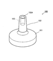
- FIG. 1 is an external view of a microphone device 100 conventionally used for this measurement.
- the microphone device 100 has a housing made up of a disk-shaped base 101 and a neck 102 erected at the center of the base 101.
- An opening 102A is opened at the top of the neck 102, and a microphone unit 103 is built inside the neck 102 toward the opening 102A.
- the microphone device 100 is installed at the listening point, the test sound is emitted from the speaker, and the test sound collected by the microphone device 100 is analyzed, so that the acoustic characteristics of the speaker and the listening room are obtained. Find out.
- the microphone device used for the above measurement is desired to have a flat frequency characteristic.
- the conventional microphone device 100 shown in FIG. 1 generates a diffracted reflection sound due to the edge of the casing base 101 or a reflection sound due to the microphone base 110 when placed on the microphone base 110.
- the sound is picked up by the microphone unit 103 together with the direct sound, and the frequency characteristics become non-flat due to the interference due to the distance difference between the direct sound and the diffracted reflected sound / reflected sound, resulting in an error in the measurement result.
- the diffracted reflected sound is a sound that is reflected on the microphone unit 103 due to the reflected sound from the surface of the microphone device 100 being circulated (diffraction), and the contribution of diffraction from the edge dominates in the characteristic change due to interference. Therefore, it is expressed as “diffracted reflection sound (by edge)”.
- An object of the present invention is to provide a microphone that suppresses changes in frequency characteristics due to diffraction and reflection as much as possible.
- the present invention is a microphone device having a casing having an opening on an upper surface thereof and an omnidirectional microphone unit built in the opening and provided inside the opening, the upper surface of the casing
- the distance from the edge defined as the boundary between the top surface and the side surface or the bottom surface over the entire circumference of the top surface to the opening varies over one-half of the entire circumference of the edge, and from the edge
- the average value of the distance to the opening is a shape shorter than one half of the wavelength of the sound wave in the frequency region where human hearing sensitivity is low.
- the frequency region where the human auditory sensitivity is low may be 10 kHz. Further, the ratio of the longest distance to the shortest distance from the edge to the opening may be doubled or more. Further, the opening may be provided at the center of a circumscribed circle having a planar shape on the upper surface. Furthermore, the planar shape of the upper surface may be a triangle.
- the present invention it is possible to minimize the influence of the diffracted sound and the reflected sound on the frequency characteristics of the sound collected by the microphone unit.
- FIGS. 5A to 5D are diagrams showing the frequency characteristics of the microphone device of the embodiment and the frequency characteristics of a comparative example.
- FIGS. 5A to 5D are diagrams showing the frequency characteristics of the microphone device of the embodiment and the frequency characteristics of a comparative example.
- FIGS. (A)-(C) are diagrams showing modifications of the microphone device to which the present invention is applied.
- FIGS. 4A to 4D are diagrams comparing frequency characteristics of the microphone device shown in FIG. 4 and the microphone device shown in FIG.
- FIG. 4 is an external view of the microphone device 1 according to the embodiment of the present invention.
- the microphone device 1 is used as a measurement microphone for measuring acoustic characteristics of an audio system and a listening room.
- the microphone device 1 includes a housing 2 and a microphone unit 3 built in the housing 2.
- the planar shape of the housing 2 (microphone device 1) is a substantially equilateral triangle, and the overall shape is a shape obtained by vertically cutting a gentle cone in accordance with the planar shape of the substantially equilateral triangle.
- the upper surface 10 of the housing 2 has an opening 11 at the center, and is inclined downward toward the side 13 that is a peripheral edge (edge) with the opening 11 as a vertex.
- the upper surface 10 is a curved surface having the highest middle point 13A closest to the opening 11 and the lowest vertex 13B farthest from the opening 11 with respect to the side 13. Therefore, the side surface 12 formed vertically downward from the side 13 of the upper surface 10 is an arch-shaped plane having the highest central portion, that is, the middle point 13A, and the lowest both ends, that is, the vertex 13B.
- the omnidirectional microphone unit 3 is provided upward in the opening 11.
- the distance of the side (edge) 13 of the upper surface 10 to the opening 11 is not constant. That is, the distance (to the opening 11) gradually changes from the middle point 13A closest to the opening 11 to the farthest vertex 13B, and the distance between the nearest point (middle point 13A) and the farthest point (vertex 13B).
- the distance ratio is about 1: 2.5.
- the planar size of the microphone device 1 is about 2 cm from the center of the opening 11 to the apex 13B, and about 1 cm from the center of the opening 11 to the middle point 13A.
- the height of the microphone 1 is about 1 .5 cm. If the speed of sound is 340 m / sec, 1 cm corresponds to 1/2 of the wavelength ⁇ of a sound wave of 17 kHz.
- the frequency characteristics are improved for the following reasons.
- the human audible range is 20 Hz to 20 kHz.
- the sensitivity of the human ear is high for sounds of 2 kHz to 4 kHz, and this sound range is easy to hear.
- the sensitivity decreases depending on the signal level, so the sound gradually becomes less concerned. For example, in the sound range around 10 kHz, it is difficult to hear and the sound is not bothered. Even if there is an influence of diffracted reflection sound, for example, if it is about 10 kHz or more, it is considered that the influence on hearing is not practical.
- FIG. 5 and 6 (D) are diagrams showing the frequency characteristics of the microphone device 1 shown in FIG.
- FIG. 5 is a diagram showing frequency characteristics when the microphone device 1 is installed in the air
- the conventional microphone device shown in FIG. 1 (FIG. 5 and FIG. 6A) is shown as a comparative example, and the microphone device having a longer neck than the conventional shape shown in FIG. 6 (B)) and the characteristics of the microphone device (FIGS. 5 and 6 (C)) in which the base shape of the pedestal is square and the neck is made longer.
- FIG. 5 shows frequency characteristics when the microphone device 1 is installed in the air
- the frequency characteristics of the audio signal collected by the microphone unit 20 are affected by the casing 2, particularly the edges. 13 is considered to be only the diffraction reflection sound.
- a dip minimum value
- the microphone device 1 according to the embodiment of the present invention shown in FIG. 5 (D) does not have extreme characteristics up and down with respect to sound coming from any angle, and 3 kHz regardless of sound coming from any angle. Since the characteristic above the degree is slightly increased, it can be corrected by a circuit at a later stage, and measurement with high accuracy is possible.
- the characteristic diagram of FIG. 6 is a frequency characteristic when the microphone device 1 is placed on a table as described above, diffraction reflection sound by the side (edge) 13 of the housing 2 and reflection by the table surface. Sound is considered to affect the frequency characteristics.
- the gain (characteristic) of the sound coming from above 20 degrees increases as the frequency increases due to the influence of the reflection from the table, and the screen is blocked by the table.
- the gain of the voice coming from the lower 10 degrees decreases as the frequency increases.
- the frequency characteristic is dip (minimum value: path difference 1 / 2 ⁇ ) due to the path difference between the direct sound and the reflected sound. ), Peak (maximum value: path difference ⁇ ) occurs.
- a dip occurs around 6500 Hz
- a dip occurs near 5000 Hz
- the lower is around 2500 Hz.
- a dip has occurred.
- the microphone device 1 of the embodiment of the present invention shown in FIG. 6D a dip occurs at a frequency of 10,000 Hz or more that has little influence on the audibility, and thus the influence on the adjustment of the hi-fi audio is small.
- the shape of the microphone device 1 shown in FIG. 4 is less affected by the diffracted reflected sound by the side (edge) 13 of the housing 2 and the reflected sound by the base surface than the other comparative columns, and even if it is affected. Easy to correct.
- the shape of the microphone device 1 of the present invention is not limited to that shown in FIG. If the distance from the side 13 of the top surface 10 of the housing 10 to the opening 11 is not constant, or the housing has a short dimension (the difference in path of the diffracted reflected sound from the direct sound is less than 1 / 2 ⁇ of the audible frequency) Well, various shapes are possible as shown in FIG. In FIG. 7A, the planar shape of the casing is a quadrangle (square). The housing of this shape is easy to manufacture and is stable when placed on a table. The thing of FIG. 7 (B) makes the planar shape of a housing
- the housing having this shape has a large distance difference between the nearest point and the farthest point, and can further reduce the influence of the diffraction reflection sound by the edge. Further, in FIG. 6C, the housing is made small enough to accommodate the microphone unit, and three legs are provided so as to fit into the recess 111 of the microphone base 110 in FIG. If it is this shape, the influence of the diffraction reflection sound by a housing
- the microphone device 1 satisfies the following conditions.
- the shape of the top surface is large, that is, the distance difference between the nearest point and the farthest point (distance ratio) so that the distance between the edge (edge) of the top surface of the housing and the microphone unit is not constant over the entire circumference of the edge. ) Is better.
- the overall size should be small, and when the distance to the farthest point is smaller than 1 ⁇ 2 ⁇ of the audible frequency, the interference band becomes a non-audible region, so there is no need to consider the shape.
- the microphone device As in the present invention, when the distance from the side 13 of the upper surface of the housing to the opening 11 varies, it has been confirmed through experiments that there is no problem in hearing if the average value of the distance is about 1 ⁇ 2 of about 10 kHz. It was. As described above, the smaller the microphone device, the better the characteristics. However, the microphone device is not stable without a certain weight for the convenience of drawing out the microphone cable.
- the position of the microphone unit 3 is not changed depending on the placement direction of the microphone device 1.
- the circumscribed circle having a planar shape (bottom shape) is preferably the same size as the circular recess, and the microphone unit 3 (opening 11) is centered on the circumscribed circle.
- FIG. 8 is a diagram comparing the frequency characteristics of the various shapes shown in FIG. 7 between the rectangular shape of the planar shape shown in FIG. 7A and the triangular shape of the planar shape shown in FIG. is there. Both have casings that meet the above conditions, and both show better characteristics than the conventional ones, but have a smaller number of corners and a distance difference (distance ratio) between the nearest and farthest points. It can be seen that the one with a large triangular casing shows better properties. It is considered that the distance ratio between the nearest point and the farthest point is preferably twice (the shape of an equilateral triangle).
- the boundary between the upper surface and the side surface of the microphone device is formed by one line (side (edge) 13), but the R surface is gently chamfered from the upper surface to the side surface.
- a wide ridgeline may be a boundary with a shape that changes to. Further, the boundary may be chamfered at a plurality of corners to form a plurality of strips. In these cases, the R-chamfered ridgeline or band-like range may be considered as an edge. In the case of a shape that gently reaches the bottom surface (without side surfaces) from the top surface, the top surface (bottom surface) contour line (planar shape) may be considered as an edge.
- the distance from each point of the upper surface side (edge) to the opening (microphone unit) (that is, the contour shape of the upper surface) gradually changed constantly, If it is a short section, there may be a portion having the same distance. If the section of the same distance is 1/2 or less of the entire circumference of the edge, it is considered that the effect of the present invention can be obtained.
- the shape of the upper surface is described as a shape in which the distance from the side (edge) of the upper surface to the opening (microphone unit) changes.
- the distance in the opening The base point is described as the center of the opening for convenience.
- the base point of the distance in the opening is not limited to the center of the opening. Any point on the edge portion of the opening may be used as a base point, or an intermediate point between any point on the edge portion and the center portion may be used as a base point. It is good also considering the whole opening part as a base point.
- the measurement microphone device 1 for measuring the acoustic characteristics of the audio system and the listening room has been described.
- the present invention is not limited to the measurement microphone device, and is applied to a recording microphone. May be.
Landscapes
- Physics & Mathematics (AREA)
- Engineering & Computer Science (AREA)
- Acoustics & Sound (AREA)
- Signal Processing (AREA)
- Health & Medical Sciences (AREA)
- Otolaryngology (AREA)
- Details Of Audible-Bandwidth Transducers (AREA)
- Obtaining Desirable Characteristics In Audible-Bandwidth Transducers (AREA)
Abstract
Provided is a microphone, wherein changes in frequency characteristics resulting from diffraction/reflection are minimized. The present invention has: a casing having an opening at the top surface thereof; and an omnidirectional microphone unit built into the casing and provided within the opening. Of the top surface of the casing, the distance to the opening from an edge demarcated as the boundary between the bottom surface or lateral surface and the top surface across the entire perimeter of the top surface changes across at least half of the entire perimeter of the edge, and the average value of the distance from the edge to the opening is configured at a size that is shorter than half of the wavelength of sound of a frequency region at which human auditory sensitivity is low.
Description
この発明は、回折音や反射音による周波数特性の変動を軽減したマイクロホン装置に関する。
The present invention relates to a microphone device that reduces fluctuations in frequency characteristics due to diffracted sound and reflected sound.
スピーカやリスニングルームの音響特性をマイクを用いて測定し、測定結果に基づいてオーディオ信号をイコライズする技術が実用化されており、更にマイクによる測定精度を高める技術も提案されている(例えば、特許文献1参照)。図1は、従来よりこの測定に用いられているマイクロホン装置100の外観図である。このマイクロホン装置100は、円板状の台部101、および、この台部101の中央に立設されたネック102からなる筐体を有している。ネック102の頂部には、開口部102Aが開設されており、このネック102の内部に開口部102Aに向けてマイクロホンユニット103が内蔵されている。上記の測定においては、このマイクロホン装置100をリスニングポイントに設置して、スピーカからテスト音声を放音し、マイクロホン装置100が収音したテスト音声を解析することにより、スピーカやリスニングルームの音響特性を割り出す。
A technique for measuring the acoustic characteristics of speakers and listening rooms using a microphone and equalizing an audio signal based on the measurement result has been put into practical use, and a technique for further improving measurement accuracy using a microphone has also been proposed (for example, patents). Reference 1). FIG. 1 is an external view of a microphone device 100 conventionally used for this measurement. The microphone device 100 has a housing made up of a disk-shaped base 101 and a neck 102 erected at the center of the base 101. An opening 102A is opened at the top of the neck 102, and a microphone unit 103 is built inside the neck 102 toward the opening 102A. In the above measurement, the microphone device 100 is installed at the listening point, the test sound is emitted from the speaker, and the test sound collected by the microphone device 100 is analyzed, so that the acoustic characteristics of the speaker and the listening room are obtained. Find out.
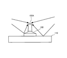
また、図2に示すような、3つの凹部101を有するマイクベース110をリスニングポイントに設置し、マイクロホン装置100を3つの凹部101に順番に載置して、順次テスト音声を収音することにより、リスニングルームの音響特性を三次元的に測定する技術も実用化されている。
In addition, by installing a microphone base 110 having three recesses 101 as shown in FIG. 2 at a listening point, and sequentially placing the microphone device 100 in the three recesses 101 to collect test sounds. In addition, a technique for three-dimensionally measuring the acoustic characteristics of a listening room has been put into practical use.
上記の測定に用いられるマイクロホン装置は、周波数特性がフラットであることが望まれる。しかし、図1に示す従来のマイクロホン装置100は、図3に示すように、筐体台部101のエッジによる回折反射音や、マイクベース110に載置した場合にはマイクベース110による反射音が、直接音とともにマイクロホンユニット103に収音され、直接音と回折反射音・反射音との距離差による干渉によって周波数特性がフラットでなくなり、測定結果に誤差が生じるという問題点があった。ここで、回折反射音とはマイクロホン装置100表面からの反射音が回り込み(回折)によってマイクロホンユニット103に収音される音のことであり、干渉による特性変化においてはエッジからの回折の寄与が支配的なため、以下「(エッジによる)回折反射音」と表現する。
The microphone device used for the above measurement is desired to have a flat frequency characteristic. However, as shown in FIG. 3, the conventional microphone device 100 shown in FIG. 1 generates a diffracted reflection sound due to the edge of the casing base 101 or a reflection sound due to the microphone base 110 when placed on the microphone base 110. The sound is picked up by the microphone unit 103 together with the direct sound, and the frequency characteristics become non-flat due to the interference due to the distance difference between the direct sound and the diffracted reflected sound / reflected sound, resulting in an error in the measurement result. Here, the diffracted reflected sound is a sound that is reflected on the microphone unit 103 due to the reflected sound from the surface of the microphone device 100 being circulated (diffraction), and the contribution of diffraction from the edge dominates in the characteristic change due to interference. Therefore, it is expressed as “diffracted reflection sound (by edge)”.
この発明は、回折や反射による周波数特性の変化を極力抑えたマイクを提供することを目的とする。
An object of the present invention is to provide a microphone that suppresses changes in frequency characteristics due to diffraction and reflection as much as possible.
この発明は、上面に開口部を有する筐体と、該筐体に内蔵され前記開口部の内部に設けられた無指向性のマイクロホンユニットと、を有するマイクロホン装置であって、前記筐体の上面は、該上面の全周にわたって前記上面と側面または底面との境界として画定されるエッジから前記開口部までの距離が、前記エッジの全周の2分の1以上にわたって変動し、前記エッジから前記開口部までの距離の平均値が人間の聴覚感度が低い周波数領域の音波の波長の2分の1よりも短い形状であることを特徴とする。
The present invention is a microphone device having a casing having an opening on an upper surface thereof and an omnidirectional microphone unit built in the opening and provided inside the opening, the upper surface of the casing The distance from the edge defined as the boundary between the top surface and the side surface or the bottom surface over the entire circumference of the top surface to the opening varies over one-half of the entire circumference of the edge, and from the edge The average value of the distance to the opening is a shape shorter than one half of the wavelength of the sound wave in the frequency region where human hearing sensitivity is low.
前記人間の聴覚感度が低い周波数領域は、10kHzでもよい。また、前記エッジから前記開口部までの最長距離と最短距離との比を2倍以上にしてもよい。また、前記開口部を、前記上面の平面形状の外接円の中心に設けてもよい。さらに、前記上面の平面形状を三角形にしてもよい。
The frequency region where the human auditory sensitivity is low may be 10 kHz. Further, the ratio of the longest distance to the shortest distance from the edge to the opening may be doubled or more. Further, the opening may be provided at the center of a circumscribed circle having a planar shape on the upper surface. Furthermore, the planar shape of the upper surface may be a triangle.
この発明によれば、マイクロホンユニットが収音した音声の周波数特性に対する回折音や反射音による影響を最小限に抑えることが可能になる。
According to the present invention, it is possible to minimize the influence of the diffracted sound and the reflected sound on the frequency characteristics of the sound collected by the microphone unit.
図4は、この発明の実施形態であるマイクロホン装置1の外観図である。このマイクロホン装置1は、オーディオシステムおよびリスニングルームの音響特性を測定する測定用マイクとして用いられるものである。マイクロホン装置1は筐体2と筐体2に内蔵されたマイクロホンユニット3を有している。筐体2(マイクロホン装置1)の平面形状は略正三角形であり、全体形状は、なだらかな円錐を、上記略正三角形の平面形状に合わせて垂直に切り落としたような形状になっている。筐体2の上面10は、中央に開口部11を有し、この開口部11を頂点として周縁(エッジ)である辺13に向けて下向きに傾斜している。このため、上面10は、辺13に関しては開口部11から最も近い中点13Aが最も高く、開口部11から最も遠い頂点13Bが最も低い、曲面になっている。したがって、上面10の辺13から下方向に垂直に形成されている側面12は、中央部すなわち中点13Aが最も高く、両端すなわち頂点13Bが最も低くなったアーチ形の平面になっている。
FIG. 4 is an external view of the microphone device 1 according to the embodiment of the present invention. The microphone device 1 is used as a measurement microphone for measuring acoustic characteristics of an audio system and a listening room. The microphone device 1 includes a housing 2 and a microphone unit 3 built in the housing 2. The planar shape of the housing 2 (microphone device 1) is a substantially equilateral triangle, and the overall shape is a shape obtained by vertically cutting a gentle cone in accordance with the planar shape of the substantially equilateral triangle. The upper surface 10 of the housing 2 has an opening 11 at the center, and is inclined downward toward the side 13 that is a peripheral edge (edge) with the opening 11 as a vertex. For this reason, the upper surface 10 is a curved surface having the highest middle point 13A closest to the opening 11 and the lowest vertex 13B farthest from the opening 11 with respect to the side 13. Therefore, the side surface 12 formed vertically downward from the side 13 of the upper surface 10 is an arch-shaped plane having the highest central portion, that is, the middle point 13A, and the lowest both ends, that is, the vertex 13B.
また、開口部11の内部に、無指向性のマイクロホンユニット3が上向きに設けられている。
Further, the omnidirectional microphone unit 3 is provided upward in the opening 11.
このような形状により、開口部11(マイクロホンユニット3)に対する上面10の辺(エッジ)13の距離は一定でなくなっている。すなわち、開口部11に最も近い中点13Aから最も遠い頂点13Bまで徐々に(開口部11までの)距離が変化しており、最近点(中点13A)と最遠点(頂点13B)との距離の比は、1:2.5程度である。
Due to such a shape, the distance of the side (edge) 13 of the upper surface 10 to the opening 11 (microphone unit 3) is not constant. That is, the distance (to the opening 11) gradually changes from the middle point 13A closest to the opening 11 to the farthest vertex 13B, and the distance between the nearest point (middle point 13A) and the farthest point (vertex 13B). The distance ratio is about 1: 2.5.
また、マイクロホン装置1の平面寸法は、開口部11の中央部から頂点13Bまでが約2cm、開口部11の中央部から中点13Aまでが約1cmであり、マイクロホン装置1の高さは約1.5cmである。音速を340m/秒とすると、1cmは17kHzの音波の波長λの1/2に相当する。
The planar size of the microphone device 1 is about 2 cm from the center of the opening 11 to the apex 13B, and about 1 cm from the center of the opening 11 to the middle point 13A. The height of the microphone 1 is about 1 .5 cm. If the speed of sound is 340 m / sec, 1 cm corresponds to 1/2 of the wavelength λ of a sound wave of 17 kHz.
このような形状にすることにより、以下の理由で周波数特性が改善される。
By adopting such a shape, the frequency characteristics are improved for the following reasons.
(1)上面10の辺13の各点から開口部11(マイクロホンユニット3)までの距離が徐々に変化しているため、辺(エッジ)13の各点から回折してマイクロホンユニット3に入射する回折反射音の経路長がそれぞれ異なり、マイクロホンユニット3に入射する直接音に対する干渉による影響が特定の周波数に集中することがない。
(1) Since the distance from each point on the side 13 of the upper surface 10 to the opening 11 (microphone unit 3) gradually changes, the light is diffracted from each point on the side (edge) 13 and enters the microphone unit 3. The path lengths of the diffracted and reflected sounds are different, and the influence of interference on the direct sound incident on the microphone unit 3 does not concentrate on a specific frequency.
(2)筐体の寸法が上記のように短いため、直接音と辺13における回折反射音の経路差が小さく、回折反射音による直接音に対する影響が現れるのが高い周波数帯域(たとえば非可聴帯域)であるため、聴感上の影響が少ない。
一般的に人間の可聴域は20Hzから20kHzとされている。その中でも、2kHzから4kHzの音に対して、人間の耳の感度は高く、この音域は聞き取りやすい。しかし、この音域より高い周波数では、信号レベルによっては感度が低下するため、段々と音が気にならなくなっていき、例えば、10kHz周辺の音域では、聞き取りにくく、音が気にならなくなる。たとえ回折反射音の影響があっても、例えば、約10kHz以上であれば、聴感上の影響は、実用上ないと考えられる。 (2) Since the dimensions of the housing are short as described above, the frequency difference between the direct sound and the diffracted reflected sound at theside 13 is small, and the influence of the diffracted reflected sound on the direct sound is high (for example, an inaudible band). ), It has little effect on hearing.
Generally, the human audible range is 20 Hz to 20 kHz. Among them, the sensitivity of the human ear is high for sounds of 2 kHz to 4 kHz, and this sound range is easy to hear. However, at frequencies higher than this sound range, the sensitivity decreases depending on the signal level, so the sound gradually becomes less concerned. For example, in the sound range around 10 kHz, it is difficult to hear and the sound is not bothered. Even if there is an influence of diffracted reflection sound, for example, if it is about 10 kHz or more, it is considered that the influence on hearing is not practical.
一般的に人間の可聴域は20Hzから20kHzとされている。その中でも、2kHzから4kHzの音に対して、人間の耳の感度は高く、この音域は聞き取りやすい。しかし、この音域より高い周波数では、信号レベルによっては感度が低下するため、段々と音が気にならなくなっていき、例えば、10kHz周辺の音域では、聞き取りにくく、音が気にならなくなる。たとえ回折反射音の影響があっても、例えば、約10kHz以上であれば、聴感上の影響は、実用上ないと考えられる。 (2) Since the dimensions of the housing are short as described above, the frequency difference between the direct sound and the diffracted reflected sound at the
Generally, the human audible range is 20 Hz to 20 kHz. Among them, the sensitivity of the human ear is high for sounds of 2 kHz to 4 kHz, and this sound range is easy to hear. However, at frequencies higher than this sound range, the sensitivity decreases depending on the signal level, so the sound gradually becomes less concerned. For example, in the sound range around 10 kHz, it is difficult to hear and the sound is not bothered. Even if there is an influence of diffracted reflection sound, for example, if it is about 10 kHz or more, it is considered that the influence on hearing is not practical.
図5(D)および図6(D)は、図4に示したマイクロホン装置1の周波数特性を示す図である。図5はマイクロホン装置1を空中に設置した場合の周波数特性を示す図、図6はマイクロホン装置1を(たとえば図3に示したような)台上に載置した場合の周波数特性を示す図である。ともに、水平(θ=0°)、上20度(θ=20°)、および、下10度(θ=-10°)から到来する3方向の音声の周波数特性を示している。なお、これらの図では、対比例として図1に示した従来形状のマイクロホン装置(図5・図6(A))、図1の従来形状よりもネックを長くした形状のマイクロホン装置(図5・図6(B))、および、台座の平面形状が四角形でよりネックを長くした形状のマイクロホン装置(図5・図6(C))の特性を併せて示している。
5 (D) and 6 (D) are diagrams showing the frequency characteristics of the microphone device 1 shown in FIG. FIG. 5 is a diagram showing frequency characteristics when the microphone device 1 is installed in the air, and FIG. 6 is a diagram showing frequency characteristics when the microphone device 1 is placed on a table (for example, as shown in FIG. 3). is there. Both show the frequency characteristics of speech in three directions coming from horizontal (θ = 0 °), upper 20 ° (θ = 20 °), and lower 10 ° (θ = −10 °). In these drawings, the conventional microphone device shown in FIG. 1 (FIG. 5 and FIG. 6A) is shown as a comparative example, and the microphone device having a longer neck than the conventional shape shown in FIG. 6 (B)) and the characteristics of the microphone device (FIGS. 5 and 6 (C)) in which the base shape of the pedestal is square and the neck is made longer.
上述したように図5はマイクロホン装置1を空中に設置した場合の周波数特性であるため、マイクロホンユニット20が収音する音声信号の周波数特性に影響を与えるのは、筐体2特に辺(エッジ)13による回折反射音のみと考えられる。
As described above, since FIG. 5 shows frequency characteristics when the microphone device 1 is installed in the air, the frequency characteristics of the audio signal collected by the microphone unit 20 are affected by the casing 2, particularly the edges. 13 is considered to be only the diffraction reflection sound.
図5(A),(B)の比較例は、ともに、どの角度から到来する音声についても2kHz以上で特性に変化があり、到来角度によってその特性変化が同じ形態でない。また、上20度から到来する音については、10kHz以下の可聴帯域にディップ(極小値)が生じている。また、図5(C)の比較例は、2kHz以上で小さい特性の変化が生じているが全体にフラットに近い。ただし、到来角度によって特性変化がばらついているため、補正は困難である。これに対して、図5(D)に示す本願実施形態のマイクロホン装置1は、どの角度から到来する音声についても極端な特性の上下がないうえに、どの角度から到来する音声であっても3kHz程度より上の特性が若干上昇するという類似した特性を示しているため、後段の回路で補正が可能であり、精度の高い測定が可能である。
In the comparative examples of FIGS. 5 (A) and 5 (B), the characteristics change at 2 kHz or more for voices coming from any angle, and the characteristic changes are not the same depending on the arrival angle. For sounds coming from the upper 20 degrees, a dip (minimum value) occurs in the audible band of 10 kHz or less. Further, in the comparative example of FIG. 5C, although a small characteristic change occurs at 2 kHz or more, the whole is almost flat. However, since the characteristic change varies depending on the arrival angle, correction is difficult. On the other hand, the microphone device 1 according to the embodiment of the present invention shown in FIG. 5 (D) does not have extreme characteristics up and down with respect to sound coming from any angle, and 3 kHz regardless of sound coming from any angle. Since the characteristic above the degree is slightly increased, it can be corrected by a circuit at a later stage, and measurement with high accuracy is possible.
次に、図6の特性図は、上述したように、マイクロホン装置1を台上に載置した場合の周波数特性であるため、筐体2の辺(エッジ)13による回折反射音および台面による反射音が周波数特性に影響を及ぼすと考えられる。
Next, since the characteristic diagram of FIG. 6 is a frequency characteristic when the microphone device 1 is placed on a table as described above, diffraction reflection sound by the side (edge) 13 of the housing 2 and reflection by the table surface. Sound is considered to affect the frequency characteristics.
図6(A)~(D)のどの例においても、台による反射の影響により、周波数が高くなるにつれて上20度から到来する音声の利得(特性)が上昇してゆき、また、台による遮蔽の影響により、周波数が高くなるにつれて下10度から到来する音声の利得が下降してゆく。さらに、上20度から到来する音声は、台で反射した反射音がマイクロホンユニット3に収音されるため、直接音と反射音の経路差によって周波数特性にディップ(極小値:経路差1/2λ)、ピーク(極大値:経路差λ)が生じる。台面とマイクロホンユニットとの距離が長いほど、すなわち、ネックが長いほど、経路差が大きくなり、ピーク、ディップの周波数が低い周波数帯域へシフトする。図6(A)の比較例では6500Hz付近にディップが生じており、図6(B)の比較例では5000Hz付近にディップが生じており、図6(C)の比較例では、より低い2500Hz付近にディップが生じている。これに対して、図6(D)に示す本願実施形態のマイクロホン装置1では、聴感上影響の少ない10000Hz以上の周波数にディップが生じており、ハイファイオーディオの調整に及ぼす影響は少 このように、図4に示したマイクロホン装置1の形状は、他の比較列に比べて筐体2の辺(エッジ)13による回折反射音および台面による反射音の影響を受けにくく、また、影響を受けても補正がしやすい。
In any of the examples shown in FIGS. 6A to 6D, the gain (characteristic) of the sound coming from above 20 degrees increases as the frequency increases due to the influence of the reflection from the table, and the screen is blocked by the table. As a result, the gain of the voice coming from the lower 10 degrees decreases as the frequency increases. Furthermore, since the sound reflected from the stage is picked up by the microphone unit 3 from the upper 20 degrees, the frequency characteristic is dip (minimum value: path difference 1 / 2λ) due to the path difference between the direct sound and the reflected sound. ), Peak (maximum value: path difference λ) occurs. The longer the distance between the base surface and the microphone unit, that is, the longer the neck, the larger the path difference, and the peak and dip frequencies shift to a lower frequency band. In the comparative example of FIG. 6 (A), a dip occurs around 6500 Hz, in the comparative example of FIG. 6 (B), a dip occurs near 5000 Hz, and in the comparative example of FIG. 6 (C), the lower is around 2500 Hz. A dip has occurred. On the other hand, in the microphone device 1 of the embodiment of the present invention shown in FIG. 6D, a dip occurs at a frequency of 10,000 Hz or more that has little influence on the audibility, and thus the influence on the adjustment of the hi-fi audio is small. The shape of the microphone device 1 shown in FIG. 4 is less affected by the diffracted reflected sound by the side (edge) 13 of the housing 2 and the reflected sound by the base surface than the other comparative columns, and even if it is affected. Easy to correct.
なお、本発明のマイクロホン装置1の形状は図4に示したものに限定されない。筐体上面10の辺13から開口部11までの距離が一定でない、若しくは、筐体の寸法が(回折反射音の直接音に対する経路差が可聴周波数の1/2λよりも)短いものであればよく、図7に示すように種々の形状が考えられる。図7(A)のものは、筐体の平面形状を四角形(正方形)にしたものである。この形状の筐体は、製造が容易で台に載置したとき安定する。図7(B)のものは、筐体の平面形状を凹多角形(ヒトデ形)にしたものである。この形状の筐体は、最近点と最遠点との距離差が大きく、エッジによる回折反射音の影響をより低減することができる。また、同図(C)のものは、筐体をマイクロホンユニットが収容できる程度の小さいものにし、図2のマイクベース110の凹部111に嵌まるように3本の脚を設けたものである。この形状であれば、筐体による回折反射音の影響を殆ど無視することができる。
The shape of the microphone device 1 of the present invention is not limited to that shown in FIG. If the distance from the side 13 of the top surface 10 of the housing 10 to the opening 11 is not constant, or the housing has a short dimension (the difference in path of the diffracted reflected sound from the direct sound is less than 1 / 2λ of the audible frequency) Well, various shapes are possible as shown in FIG. In FIG. 7A, the planar shape of the casing is a quadrangle (square). The housing of this shape is easy to manufacture and is stable when placed on a table. The thing of FIG. 7 (B) makes the planar shape of a housing | casing into the concave polygon (starfish shape). The housing having this shape has a large distance difference between the nearest point and the farthest point, and can further reduce the influence of the diffraction reflection sound by the edge. Further, in FIG. 6C, the housing is made small enough to accommodate the microphone unit, and three legs are provided so as to fit into the recess 111 of the microphone base 110 in FIG. If it is this shape, the influence of the diffraction reflection sound by a housing | casing can be disregarded almost.
このように、マイクロホン装置1は以下のような条件を満たすことが望まれる。筐体上面の辺(エッジ)とマイクロホンユニットとの距離がエッジの全周にわたって一定にならないように、上面の形状は出入りの大きい形、すなわち、最近点と最遠点との距離差(距離比)が大きいほうがよい。ただし、全体の大きさは小さいほうがよく、最遠点までの距離が可聴周波数の1/2λよりも小さい場合には干渉帯域が非可聴領域になるため形状を考慮する必要がなくなる。本発明のように筐体上面の辺13から開口部11までの距離が変動する場合は該距離の平均値が10kHz程度の1/2程度であれば聴感上問題がないことが実験により確かめられた。このように、マイクロホン装置は小さいほど特性がよくなるが、マイクケーブルを引き出す都合上ある程度の重量がないと安定しない。
Thus, it is desirable that the microphone device 1 satisfies the following conditions. The shape of the top surface is large, that is, the distance difference between the nearest point and the farthest point (distance ratio) so that the distance between the edge (edge) of the top surface of the housing and the microphone unit is not constant over the entire circumference of the edge. ) Is better. However, the overall size should be small, and when the distance to the farthest point is smaller than ½λ of the audible frequency, the interference band becomes a non-audible region, so there is no need to consider the shape. As in the present invention, when the distance from the side 13 of the upper surface of the housing to the opening 11 varies, it has been confirmed through experiments that there is no problem in hearing if the average value of the distance is about ½ of about 10 kHz. It was. As described above, the smaller the microphone device, the better the characteristics. However, the microphone device is not stable without a certain weight for the convenience of drawing out the microphone cable.
また、図2に示したマイクベース110の円形の凹部111に、マイクロホン装置1を載置して測定を行う場合に、マイクロホン装置1の載置方向によってマイクロホンユニット3の位置が変化しないように、平面形状(底面の形状)の外接円は円形の凹部と同じ大きさであり、且つ、この外接円の中心にマイクロホンユニット3(開口部11)がくるような形状にすることが好ましい。
Further, when the microphone device 1 is placed in the circular recess 111 of the microphone base 110 shown in FIG. 2 and measurement is performed, the position of the microphone unit 3 is not changed depending on the placement direction of the microphone device 1. The circumscribed circle having a planar shape (bottom shape) is preferably the same size as the circular recess, and the microphone unit 3 (opening 11) is centered on the circumscribed circle.
図8は、図7に示した種々の形状のうち同図(A)に示した平面形状が四角形のものと、図4に示した平面形状が三角形のものとの周波数特性を比較した図である。ともに、上記の条件を満たした形状の筐体を有し、両方とも従来のものに比べて良好な特性を示しているが、角数が少なく最近点と最遠点との距離差(距離比)が大きい三角形の筐体を有するもののほうがより良好な特性を示していることが判る。最近点と最遠点との距離比は、2倍(正三角形の形状)であることがより好ましいと考えられる。
FIG. 8 is a diagram comparing the frequency characteristics of the various shapes shown in FIG. 7 between the rectangular shape of the planar shape shown in FIG. 7A and the triangular shape of the planar shape shown in FIG. is there. Both have casings that meet the above conditions, and both show better characteristics than the conventional ones, but have a smaller number of corners and a distance difference (distance ratio) between the nearest and farthest points. It can be seen that the one with a large triangular casing shows better properties. It is considered that the distance ratio between the nearest point and the farthest point is preferably twice (the shape of an equilateral triangle).
図4および図7に示した実施形態では、マイク装置の上面と側面との境界が1本の線状(辺(エッジ)13)で形成されているが、上面から側面へR面取りされてなだらかに変化する形状で幅のある稜線が境界となっていてもよい。また、複数の角で面取りされて境界が複数の帯状になっていてもよい。これらの場合、このR面取りされた稜線状または帯状の幅のある範囲をエッジと考えればよい。また、上面からなだらかに底面に至る(側面のない)形状の場合には、上面(底面)輪郭線(平面形状)をエッジと考えればよい。
In the embodiment shown in FIGS. 4 and 7, the boundary between the upper surface and the side surface of the microphone device is formed by one line (side (edge) 13), but the R surface is gently chamfered from the upper surface to the side surface. A wide ridgeline may be a boundary with a shape that changes to. Further, the boundary may be chamfered at a plurality of corners to form a plurality of strips. In these cases, the R-chamfered ridgeline or band-like range may be considered as an edge. In the case of a shape that gently reaches the bottom surface (without side surfaces) from the top surface, the top surface (bottom surface) contour line (planar shape) may be considered as an edge.
図4および図7に示した実施形態では、上面の辺(エッジ)の各点から開口部(マイクロホンユニット)までの距離(すなわち上面の輪郭形状)が徐々に常に変化する形状であったが、短い区間であれば距離が同じ部分があっても構わない。同じ距離の区間がエッジの全周の1/2以下であれば、本願発明の効果を奏することが可能であると考えられる。
図4および図7に示した実施形態では、上面の形状について、上面の辺(エッジ)から開口部(マイクロホンユニット)までの距離が変化する形状として説明しており、ここでは、開口部における距離の基点は、便宜上、開口部の中心として説明している。しかしながら、本発明の実施形態において、この開口部における距離の基点は、開口部の中心に限定されない。開口部の縁部分のいずれかの点を基点としてもよいし、また、縁部分のいずれかの点と中心部との中間点を基点としてもよい。開口部全体を基点としてもよい。 In the embodiment shown in FIG. 4 and FIG. 7, the distance from each point of the upper surface side (edge) to the opening (microphone unit) (that is, the contour shape of the upper surface) gradually changed constantly, If it is a short section, there may be a portion having the same distance. If the section of the same distance is 1/2 or less of the entire circumference of the edge, it is considered that the effect of the present invention can be obtained.
In the embodiment shown in FIG. 4 and FIG. 7, the shape of the upper surface is described as a shape in which the distance from the side (edge) of the upper surface to the opening (microphone unit) changes. Here, the distance in the opening The base point is described as the center of the opening for convenience. However, in the embodiment of the present invention, the base point of the distance in the opening is not limited to the center of the opening. Any point on the edge portion of the opening may be used as a base point, or an intermediate point between any point on the edge portion and the center portion may be used as a base point. It is good also considering the whole opening part as a base point.
なお、この実施形態は、オーディオシステムおよびリスニングルームの音響特性を測定するための測定用のマイクロホン装置1について説明したが、本発明は測定用のマイクロホン装置に限定されず、録音用のマイクロホンに適用してもよい。
In this embodiment, the measurement microphone device 1 for measuring the acoustic characteristics of the audio system and the listening room has been described. However, the present invention is not limited to the measurement microphone device, and is applied to a recording microphone. May be.
本発明を詳細にまた特定の実施態様を参照して説明したが、本発明の精神と範囲を逸脱することなく様々な変更や修正を加えることができることは当業者にとって明らかである。
本出願は、2012年2月21日出願の日本特許出願(特願2012-034892)および2012年12月10日出願の日本特許出願(特願2012-269546)に基づくものであり、その内容はここに参照として取り込まれる。 Although the present invention has been described in detail and with reference to specific embodiments, it will be apparent to those skilled in the art that various changes and modifications can be made without departing from the spirit and scope of the invention.
This application is based on a Japanese patent application filed on February 21, 2012 (Japanese Patent Application No. 2012-034892) and a Japanese patent application filed on December 10, 2012 (Japanese Patent Application No. 2012-269546). Incorporated herein by reference.
1 マイクロホン装置
2 筐体
3 マイクロホンユニット
11 開口部
13 辺(エッジ)
110 マイクベース
111 凹部 DESCRIPTION OFSYMBOLS 1 Microphone apparatus 2 Case 3 Microphone unit 11 Opening part 13 Side (edge)
110Microphone base 111 Recess
2 筐体
3 マイクロホンユニット
11 開口部
13 辺(エッジ)
110 マイクベース
111 凹部 DESCRIPTION OF
110
Claims (5)
- 上面に開口部を有する筐体と、該筐体に内蔵され前記開口部の内部に設けられた無指向性のマイクロホンユニットと、を有するマイクロホン装置であって、
前記筐体の上面は、該上面の全周にわたって前記上面と側面または底面との境界として画定されるエッジから前記開口部までの距離が、前記エッジの全周の2分の1以上にわたって変動し、前記エッジから前記開口部までの距離の平均値が人間の聴覚感度が低い周波数領域の音波の波長の2分の1よりも短い形状であるマイクロホン装置。 A microphone device having a housing having an opening on an upper surface, and an omnidirectional microphone unit built in the housing and provided inside the opening,
In the upper surface of the casing, the distance from the edge defined as the boundary between the upper surface and the side surface or the bottom surface over the entire circumference of the upper surface and the opening varies over one half or more of the entire circumference of the edge. The microphone device having a shape in which the average value of the distance from the edge to the opening is shorter than one half of the wavelength of the sound wave in the frequency region where human hearing sensitivity is low. - 前記人間の聴覚感度が低い周波数領域は、10kHzである請求項1に記載のマイクロホン装置。 The microphone device according to claim 1, wherein the frequency region where the human auditory sensitivity is low is 10 kHz.
- 前記エッジから前記開口部までの最長距離と最短距離との比が2倍以上である請求項1または請求項2に記載のマイクロホン装置。 The microphone device according to claim 1 or 2, wherein a ratio of a longest distance to a shortest distance from the edge to the opening is twice or more.
- 前記開口部は、前記上面の平面形状の外接円の中心に設けられている請求項1乃至請求項3のいずれかに記載のマイクロホン装置。 The microphone device according to any one of claims 1 to 3, wherein the opening is provided at a center of a circumscribed circle having a planar shape on the upper surface.
- 前記上面は、平面形状が三角形に構成されている請求項1乃至請求項4のいずれかに記載のマイクロホン装置。 The microphone device according to any one of claims 1 to 4, wherein the upper surface has a triangular planar shape.
Priority Applications (3)
| Application Number | Priority Date | Filing Date | Title |
|---|---|---|---|
| CN201380010390.4A CN104145483B (en) | 2012-02-21 | 2013-02-14 | Microphone apparatus |
| EP13752212.4A EP2819427B1 (en) | 2012-02-21 | 2013-02-14 | Microphone device |
| US14/379,938 US9407983B2 (en) | 2012-02-21 | 2013-02-14 | Microphone device |
Applications Claiming Priority (4)
| Application Number | Priority Date | Filing Date | Title |
|---|---|---|---|
| JP2012-034892 | 2012-02-21 | ||
| JP2012034892 | 2012-02-21 | ||
| JP2012-269546 | 2012-12-10 | ||
| JP2012269546A JP5708629B2 (en) | 2012-02-21 | 2012-12-10 | Microphone device |
Publications (1)
| Publication Number | Publication Date |
|---|---|
| WO2013125434A1 true WO2013125434A1 (en) | 2013-08-29 |
Family
ID=49005621
Family Applications (1)
| Application Number | Title | Priority Date | Filing Date |
|---|---|---|---|
| PCT/JP2013/053499 WO2013125434A1 (en) | 2012-02-21 | 2013-02-14 | Microphone device |
Country Status (5)
| Country | Link |
|---|---|
| US (1) | US9407983B2 (en) |
| EP (1) | EP2819427B1 (en) |
| JP (1) | JP5708629B2 (en) |
| CN (1) | CN104145483B (en) |
| WO (1) | WO2013125434A1 (en) |
Families Citing this family (1)
| Publication number | Priority date | Publication date | Assignee | Title |
|---|---|---|---|---|
| US10419850B2 (en) * | 2017-01-18 | 2019-09-17 | Trident Acoustics | Dynamic boundary pressure zone microphone |
Citations (3)
| Publication number | Priority date | Publication date | Assignee | Title |
|---|---|---|---|---|
| JPH0298592U (en) * | 1989-01-25 | 1990-08-06 | ||
| JP2009037143A (en) | 2007-08-03 | 2009-02-19 | Yamaha Corp | Auxiliary appliance for measurement |
| JP2010278988A (en) * | 2009-06-01 | 2010-12-09 | Audio Technica Corp | Boundary microphone and desk-top electro-acoustic transducer |
Family Cites Families (32)
| Publication number | Priority date | Publication date | Assignee | Title |
|---|---|---|---|---|
| GB2101449B (en) * | 1981-06-17 | 1985-03-20 | Rolls Royce | Microphone device for noise measurement |
| JPS5957596A (en) * | 1982-09-27 | 1984-04-03 | Sony Corp | Microphone device |
| DE3926884A1 (en) * | 1989-08-16 | 1991-02-21 | Neumann Gmbh Georg | ELECTROACOUSTIC CONVERTER |
| US5121426A (en) * | 1989-12-22 | 1992-06-09 | At&T Bell Laboratories | Loudspeaking telephone station including directional microphone |
| US6009184A (en) * | 1996-10-08 | 1999-12-28 | Umevoice, Inc. | Noise control device for a boom mounted noise-canceling microphone |
| US5854848A (en) * | 1996-10-08 | 1998-12-29 | Umevoice, Inc. | Noise control device |
| JP3722335B2 (en) * | 1998-02-17 | 2005-11-30 | ヤマハ株式会社 | Reverberation equipment |
| US6285772B1 (en) * | 1999-07-20 | 2001-09-04 | Umevoice, Inc. | Noise control device |
| US6396932B1 (en) * | 1999-07-21 | 2002-05-28 | Umevoice, Inc. | Pluggable noise-controlling apparatus and method |
| US7339605B2 (en) * | 2004-04-16 | 2008-03-04 | Polycom, Inc. | Conference link between a speakerphone and a video conference unit |
| JP2005333180A (en) * | 2004-05-18 | 2005-12-02 | Audio Technica Corp | Boundary microphone |
| US8644525B2 (en) * | 2004-06-02 | 2014-02-04 | Clearone Communications, Inc. | Virtual microphones in electronic conferencing systems |
| JP4521242B2 (en) * | 2004-09-30 | 2010-08-11 | 株式会社オーディオテクニカ | Boundary microphone |
| JP4471818B2 (en) * | 2004-11-17 | 2010-06-02 | 株式会社オーディオテクニカ | Boundary microphone |
| US8130977B2 (en) * | 2005-12-27 | 2012-03-06 | Polycom, Inc. | Cluster of first-order microphones and method of operation for stereo input of videoconferencing system |
| DE102006011155A1 (en) * | 2006-03-10 | 2007-09-13 | Robert Bosch Gmbh | ultrasonic sensor |
| JP2008167175A (en) * | 2006-12-28 | 2008-07-17 | Audio Technica Corp | Boundary microphone |
| JP2008187581A (en) * | 2007-01-31 | 2008-08-14 | Audio Technica Corp | Boundary microphone |
| JP5201656B2 (en) * | 2007-10-16 | 2013-06-05 | 株式会社オーディオテクニカ | Boundary microphone |
| US7787331B2 (en) * | 2008-05-13 | 2010-08-31 | Bbn Technologies, Corp. | Sensor for airborne shooter localization system |
| AU2008359684B2 (en) * | 2008-07-24 | 2014-03-06 | Genelec Oy | Nested compound loudspeaker drive unit |
| JP2010226429A (en) * | 2009-03-24 | 2010-10-07 | Audio Technica Corp | Boundary microphone |
| US8989399B2 (en) * | 2009-04-14 | 2015-03-24 | Lloyd Baggs Innovations, Llc | Reflection cancelling boundary microphones and amplification systems incorporating reflection cancelling boundary microphones |
| JP5432603B2 (en) * | 2009-06-22 | 2014-03-05 | 株式会社オーディオテクニカ | Boundary microphone |
| JP5441540B2 (en) * | 2009-07-22 | 2014-03-12 | 株式会社オーディオテクニカ | Boundary microphone |
| JP5568915B2 (en) * | 2009-07-29 | 2014-08-13 | ヤマハ株式会社 | External device controller |
| JP5534822B2 (en) * | 2010-01-08 | 2014-07-02 | 株式会社オーディオテクニカ | Boundary microphone |
| JP5517154B2 (en) * | 2010-01-25 | 2014-06-11 | 株式会社オーディオテクニカ | Boundary microphone |
| JP5639845B2 (en) * | 2010-10-25 | 2014-12-10 | 株式会社オーディオテクニカ | Boundary microphone |
| US8989815B2 (en) * | 2012-11-24 | 2015-03-24 | Polycom, Inc. | Far field noise suppression for telephony devices |
| US20140211974A1 (en) * | 2013-01-25 | 2014-07-31 | William J Pielsticker | Weatherproof Windscreen for Microphone |
| US9271069B2 (en) * | 2014-01-27 | 2016-02-23 | Revolabs, Inc | Microphone housing arrangement for an audio conference system |
-
2012
- 2012-12-10 JP JP2012269546A patent/JP5708629B2/en active Active
-
2013
- 2013-02-14 US US14/379,938 patent/US9407983B2/en active Active
- 2013-02-14 WO PCT/JP2013/053499 patent/WO2013125434A1/en active Application Filing
- 2013-02-14 CN CN201380010390.4A patent/CN104145483B/en active Active
- 2013-02-14 EP EP13752212.4A patent/EP2819427B1/en active Active
Patent Citations (3)
| Publication number | Priority date | Publication date | Assignee | Title |
|---|---|---|---|---|
| JPH0298592U (en) * | 1989-01-25 | 1990-08-06 | ||
| JP2009037143A (en) | 2007-08-03 | 2009-02-19 | Yamaha Corp | Auxiliary appliance for measurement |
| JP2010278988A (en) * | 2009-06-01 | 2010-12-09 | Audio Technica Corp | Boundary microphone and desk-top electro-acoustic transducer |
Also Published As
| Publication number | Publication date |
|---|---|
| EP2819427A4 (en) | 2015-10-28 |
| JP2013201749A (en) | 2013-10-03 |
| EP2819427A1 (en) | 2014-12-31 |
| JP5708629B2 (en) | 2015-04-30 |
| US20150373438A1 (en) | 2015-12-24 |
| CN104145483A (en) | 2014-11-12 |
| US9407983B2 (en) | 2016-08-02 |
| EP2819427B1 (en) | 2018-01-31 |
| CN104145483B (en) | 2016-02-10 |
Similar Documents
| Publication | Publication Date | Title |
|---|---|---|
| JP6584596B2 (en) | Loudspeaker with reduced audio coloration caused by reflection from the surface | |
| US9961437B2 (en) | Dome shaped microphone array with circularly distributed microphones | |
| US7278513B2 (en) | Internal lens system for loudspeaker waveguides | |
| US8290195B2 (en) | Acoustic radiation pattern adjusting | |
| US9894433B2 (en) | Audio wave guide | |
| US20090226004A1 (en) | Microphone aperture | |
| US20090245535A1 (en) | Loudspeaker Apparatus for Radiating Acoustic Waves in a Hemisphere | |
| US10667044B2 (en) | Diffuser and loudspeaker | |
| WO2013125434A1 (en) | Microphone device | |
| AU2018204500A1 (en) | Loudspeaker | |
| US10341761B2 (en) | Acoustic waveguide for audio speaker | |
| US20180132034A1 (en) | Controlled array loudspeaker | |
| US8379892B1 (en) | Array of high frequency loudspeakers | |
| JPH11262078A (en) | Loudspeaker equipment | |
| WO2023282349A1 (en) | Speaker unit | |
| CN216752072U (en) | Linear array sound box with coaxial loudspeaker and high-pitch horn combination | |
| US20190052956A1 (en) | Planar loudspeaker manifold for improved sound dispersion | |
| KR101754521B1 (en) | A dodecahedron loudspeaker system using a coaxial two way unit | |
| JPS6090499A (en) | Sound collector | |
| CN114422911A (en) | Linear array sound box with coaxial loudspeaker and high-pitch horn combination | |
| CA2832561C (en) | Acoustic panel | |
| JP2020178146A (en) | Ceiling embedded speaker | |
| JP2020178147A (en) | Ceiling embedded speaker |
Legal Events
| Date | Code | Title | Description |
|---|---|---|---|
| 121 | Ep: the epo has been informed by wipo that ep was designated in this application |
Ref document number: 13752212 Country of ref document: EP Kind code of ref document: A1 |
|
| WWE | Wipo information: entry into national phase |
Ref document number: 14379938 Country of ref document: US Ref document number: 2013752212 Country of ref document: EP |
|
| NENP | Non-entry into the national phase |
Ref country code: DE |