WO2013124881A1 - Wireless communication method, wireless communication system, radio station, and radio terminal - Google Patents
Wireless communication method, wireless communication system, radio station, and radio terminal Download PDFInfo
- Publication number
- WO2013124881A1 WO2013124881A1 PCT/JP2012/001127 JP2012001127W WO2013124881A1 WO 2013124881 A1 WO2013124881 A1 WO 2013124881A1 JP 2012001127 W JP2012001127 W JP 2012001127W WO 2013124881 A1 WO2013124881 A1 WO 2013124881A1
- Authority
- WO
- WIPO (PCT)
- Prior art keywords
- node
- wireless terminal
- signal
- information
- wireless
- Prior art date
Links
Images


Classifications
-
- H—ELECTRICITY
- H04—ELECTRIC COMMUNICATION TECHNIQUE
- H04W—WIRELESS COMMUNICATION NETWORKS
- H04W52/00—Power management, e.g. TPC [Transmission Power Control], power saving or power classes
- H04W52/04—TPC
- H04W52/38—TPC being performed in particular situations
- H04W52/50—TPC being performed in particular situations at the moment of starting communication in a multiple access environment
-
- H—ELECTRICITY
- H04—ELECTRIC COMMUNICATION TECHNIQUE
- H04W—WIRELESS COMMUNICATION NETWORKS
- H04W52/00—Power management, e.g. TPC [Transmission Power Control], power saving or power classes
- H04W52/04—TPC
- H04W52/18—TPC being performed according to specific parameters
- H04W52/24—TPC being performed according to specific parameters using SIR [Signal to Interference Ratio] or other wireless path parameters
- H04W52/246—TPC being performed according to specific parameters using SIR [Signal to Interference Ratio] or other wireless path parameters where the output power of a terminal is based on a path parameter calculated in said terminal
-
- H—ELECTRICITY
- H04—ELECTRIC COMMUNICATION TECHNIQUE
- H04W—WIRELESS COMMUNICATION NETWORKS
- H04W76/00—Connection management
- H04W76/10—Connection setup
Definitions
- the present invention relates to a wireless communication method, a wireless communication system, a wireless station, and a wireless terminal.
- next-generation wireless communication technologies have been discussed in order to further increase the speed and capacity of wireless communication in wireless communication systems such as mobile phone systems.
- 3GPP 3rd Generation Partnership Project
- LTE Long Term Evolution
- LTE-A LTE-Advanced
- coordinated multipoint (hereinafter also referred to as CoMP) communication is being studied in order to reduce inter-cell interference and improve received signal strength.
- multipoint cooperative communication a plurality of geographically separated points (hereinafter also referred to as nodes) perform communication in cooperation. Each point corresponds to, for example, a base station, a communication unit, an antenna, or a cell formed by these. Thereby, dynamic adjustment of transmission or reception between multiple points is performed.
- downlink multipoint cooperative communication a method of jointly transmitting a plurality of points to a wireless terminal has been studied.
- uplink multipoint cooperative communication a method of combining signals received at a plurality of points while communicating between the points has been studied.
- the disclosed technology has been made in view of the above, and provides a wireless communication method, a wireless communication system, a wireless station, and a wireless terminal capable of improving transmission control characteristics in multipoint cooperative communication. Objective.
- a wireless communication method disclosed in the present application is a wireless communication including a wireless terminal in which one cell includes a plurality of nodes and capable of cooperative communication with one or more nodes.
- a wireless communication method in a system wherein, in the cell, before establishing a connection with the wireless terminal, information on a reference signal for each node is notified to the wireless terminal, and the wireless terminal refers to the node for each node.
- a signal for establishing the connection is transmitted with a parameter corresponding to the communication quality of each node acquired using information related to the signal.
- FIG. 1 is a diagram illustrating a configuration of a wireless communication system according to the first embodiment.
- FIG. 2 is a functional block diagram showing the configuration of the radio station according to the first embodiment.
- FIG. 3 is a functional block diagram showing the configuration of the wireless terminal according to the first embodiment.
- FIG. 4 is a diagram illustrating a hardware configuration of the radio station according to the first embodiment.
- FIG. 5 is a diagram illustrating a hardware configuration of the wireless terminal according to the first embodiment.
- FIG. 6 is a sequence diagram for explaining the operation of the wireless communication system according to the first embodiment.
- FIG. 7 is a diagram illustrating a configuration of a wireless communication system according to the second embodiment.
- FIG. 8 is a functional block diagram showing a configuration of a radio station according to the second embodiment.
- FIG. 1 is a diagram illustrating a configuration of a wireless communication system according to the first embodiment.
- FIG. 2 is a functional block diagram showing the configuration of the radio station according to the first embodiment.
- FIG. 3
- FIG. 9 is a functional block diagram showing the configuration of the wireless terminal according to the second embodiment.
- FIG. 10 is a sequence diagram for explaining the operation of the wireless communication system according to the second embodiment.
- FIG. 11 is a diagram illustrating an example of control information in the wireless communication system according to the second embodiment.
- FIG. 12 is a flowchart for explaining the operation of the radio communication system according to the third embodiment.
- FIG. 13 is a flowchart for explaining the operation of the wireless communication system according to the fourth embodiment.
- FIG. 14 is a diagram illustrating an example of control information in the wireless communication system according to the fourth embodiment.
- FIG. 15 is a diagram illustrating an example of control information in the wireless communication system according to the fourth embodiment.
- FIG. 16 is a diagram illustrating an example of control information in the wireless communication system according to the fourth embodiment.
- FIG. 17 is a diagram illustrating an example of control information in the wireless communication system according to the fourth embodiment.
- FIG. 1 shows a configuration of a wireless communication system 1 according to the first embodiment.
- the wireless communication system 1 includes a wireless station 4 and wireless terminals 7 and 8.
- the radio station 4 is connected to the host device 3 via a wired connection, and the host device 3 is connected to the network 2 via a wired connection.
- the radio station 4 has a control unit 9 and remote units 5 and 6.
- the control unit 9 can be realized as eNodeB (evolved (Node B), for example.
- the remote units 5 and 6 can be realized as, for example, RRH (Remote Radio Radio Head) included in the eNodeB.
- the control unit 9, the remote unit 5, and the remote unit 6 each have an antenna (point) and are arranged at points separated from each other.
- the control unit 9 and the remote units 5 and 6 correspond to nodes.
- the control unit 9 forms a cell C1, and the remote units 5 and 6 form cover areas R1 and R2 that overlap the cell C1, respectively.
- the wireless terminals 7 and 8 are located in the cell C1. At this time, the wireless terminal 7 is included in the cover area R1.
- the control unit 9 and the remote units 5 and 6 communicate with each other via a wired connection and also perform CoMP communication with the wireless terminals 7 and 8.
- data is transmitted from one or more nodes selected as a set to be used for downlink CoMP communication among the control unit 9 and the remote units 5 and 6 to the radio terminal 7.
- Send the combined
- one or more nodes selected as a set to be used for uplink CoMP communication among the control unit 9 and the remote units 5 and 6 are transmitted from the radio terminal 7. Are received, and the received signal is synthesized between the nodes.
- FIG. 2 is a functional block diagram showing the configuration of the wireless station 4.
- the control unit 9 of the wireless station 4 includes an antenna 10, a transmission unit 11, a reception unit 12, and a control unit 13.
- the remote unit 5 of the wireless station 4 includes an antenna 14, a transmission unit 15, and a reception unit 16.
- the remote unit 6 of the wireless station 4 includes an antenna 17, a transmission unit 18, and a reception unit 19. Prepare. Each of these components is connected so that signals and data can be input and output in one direction or in both directions.
- the constituent parts 14 to 19 of the remote units 5 and 6 are the same as the constituent antennas 14 to 16 of the control unit 9.
- the transmission unit 11 transmits data signals and control signals via the antenna 11.
- the signal to be transmitted includes, for example, information on a reference signal for each cell, information on a reference signal for each node, a reference signal for each cell, a reference signal for each node, and a parameter for setting uplink transmission power.
- the receiving unit 12 receives data signals and control signals transmitted from the wireless terminals 7 and 8 via the antenna 11.
- the received signal includes, for example, a signal for establishing a connection.
- the antenna 11 may be separated for transmission and reception.
- the control unit 13 acquires information and signals from the host device 3 and other wireless stations via a wired connection or a wireless connection.
- the control unit 13 outputs data to be transmitted and control information to the transmission units 11, 15 and 18.
- the control unit 13 inputs received data and control information from the receiving units 12, 16, and 19.
- the control unit 13 notifies the system information in the cell C1.
- the system information is broadcast on a broadcast channel or a shared channel designated by the broadcast channel.
- the system information includes, for example, information related to the reference signal for each cell and information related to the reference signal for each node.
- the control unit 13 causes the transmission units 11, 15, and 18 to transmit a reference signal.
- the transmission unit 11 uses a reference signal for each cell as a reference signal for measuring communication quality, and the transmission units 15 and 18 each use the remote unit 5 as a reference signal for measuring communication quality.
- 6 is used as a reference signal for each node.
- FIG. 3 is a functional block diagram showing the configuration of the wireless terminal 7.
- the wireless terminal 7 includes an antenna 20, a transmission unit 21, a reception unit 22, and a control unit 23. Each of these components is connected so that signals and data can be input and output in one direction or in both directions.
- the functional configuration and hardware configuration of the wireless terminal 8 are the same as the functional configuration and hardware configuration of the wireless terminal 7.
- the transmission unit 21 transmits a data signal and a control signal via the antenna 20.
- the signal to be transmitted includes, for example, a signal for establishing a connection.
- the receiving unit 12 receives the data signal and the control signal transmitted from the wireless terminal via the antenna 20.
- the received signal includes, for example, information on a reference signal for each cell, information on a reference signal for each node, a reference signal for each cell, a reference signal for each node, and a parameter for determining uplink transmission power.
- the antenna 20 may be separated for transmission and reception.
- the control unit 23 outputs data to be transmitted and control information to the transmission unit 21.
- the control unit 23 inputs data and control information received from the receiving unit 22.
- the control unit 23 determines, based on the received information on the reference signal for each cell and the information on the reference signal for each node, from the received signal of the entire reference signal transmitted from the wireless station 4 for each node before connection establishment.
- the reference signal reception level is acquired, and the communication quality for each node is acquired.
- the control unit 23 determines the transmission power of a signal for establishing a connection from the acquired communication quality for each node.
- FIG. 4 is a diagram illustrating a hardware configuration of the wireless station 4.
- the wireless station 4 includes, as hardware components, for example, RF circuits (Radio Frequency) 31, 38, and 42 including antennas 30, 37, and 41 and DSPs (Digital Signal Processors) 32 and 39. , 43, a CPU (Central Processing Unit) 34, memories 33, 35, 40, and 44, and a network IF (Interface) 36.
- the CPU 34 is connected through a network IF 36 such as a switch so that various signals and data can be input and output.
- the memories 33, 35, 40, and 44 include, for example, at least one of RAM (Random Access Memory), ROM (Read Only Memory), and flash memory such as SDRAM (Synchronous Dynamic Random Access Memory). Store the data.
- the transmitters 11, 15, 18 and the receivers 12, 16, 19 are realized by integrated circuits such as RF circuits 31, 38, 42 and DSPs 32, 39, 43, for example.
- the control unit 13 is realized by an integrated circuit such as a CPU 34, for example.
- the control unit 9 corresponds to the components 30 to 36
- the remote unit 5 corresponds to the components 37 to 40
- the remote unit 6 corresponds to the components 41 to 44.
- FIG. 5 is a diagram illustrating a hardware configuration of the wireless terminal 7.
- the wireless terminal 7 includes, as hardware components, an RF circuit 51 including an antenna 50, a CPU 52, and a memory 53, for example.
- RF circuit 51 including an antenna 50
- CPU 52 a CPU 52
- memory 53 for example.
- LCD Liquid Crystal Display
- the memory 53 includes, for example, RAM such as SDRAM, ROM, and flash memory, and stores programs, control information, and data.
- the transmission unit 21 and the reception unit 22 are realized by the RF circuit 51, for example.
- the control unit 23 is realized by an integrated circuit such as a CPU 52, for example.
- FIG. 6 is a sequence diagram for explaining an operation related to connection establishment of the wireless communication system 1.
- the control unit 9, the remote unit 5, and the remote unit 6 of the wireless station 4 are provided as nodes so that CoMP communication is possible.
- the cell identification information is common. That is, the cell identification information is common to the control unit 9 and the remote units 5 and 6. Then, a reference signal for each cell is assigned in association with the cell identification information.
- Cell identification information or the like of the cell C1 is broadcast in the cell C1 as system information, for example.
- the wireless terminal 7 converts the reference signals transmitted from the control unit 9 and the remote units 5 and 6 to the same pattern. Therefore, it cannot be separated for each transmission source, and is received as a synthesized signal. Then, the wireless terminal 7 acquires the communication quality based on the reception level of the combined signal and determines the transmission power. In this case, an appropriate transmission power may not be determined.
- the wireless terminal 7 acquires the communication quality for each node using the reception level of the reference signal for each node. And the radio
- the wireless terminal 7 in order to acquire the reception level separately from the reference signal for each node, it is necessary for the wireless terminal 7 to acquire information regarding the reference signal for each node in advance.
- the wireless terminal 7 periodically transmits information on the reference signal for each node as wireless resource information from a connected wireless station via an individual control channel or data channel. Can be obtained. And it is possible to acquire communication quality for every node using the reception level of the reference signal for every node, and to determine transmission power.
- the wireless terminal 7 cannot acquire information on the reference signal for each node through the individual control channel or data channel as the wireless resource information. For this reason, before the connection is established, the control unit 9 and the remote units 5 and 6 each transmit a common reference signal for each cell. The wireless terminal 7 receives the reference signal transmitted from the control unit 9 and the remote units 5 and 6 as a synthesized signal. Then, the wireless terminal 7 acquires the communication quality based on the reception level of the signal synthesized in this way, and determines the initial transmission power of the signal for establishing the connection. Then, after establishing a communication link with the cell C1, the wireless terminal 7 acquires wireless resource information, and shifts to CoMP communication with a node included in the cell C1.
- the radio terminal 7 is a signal for establishing a connection with a relatively large initial transmission power so that a signal for establishing a connection reaches the entire cell C1 in order to establish a communication link with the cell C1. Is assumed to be sent. Then, for example, there is a risk of interference or contention for the wireless terminal 8 that is located in the cell C1 and tries to establish a connection.
- an operation for establishing a connection is performed as follows.
- the wireless terminal 7 located in the cell C1 is in a state where the connection with the wireless station 4 has not been established, and an operation of establishing a connection between the wireless station 4 and the wireless terminal 7 will be described as an example.
- the radio station 4 broadcasts information on the reference signal for each node in the cell C1 (S1).
- information on the reference signal for each node is included in the system information and is broadcast on a broadcast channel or a shared channel in which radio resources are specified by the broadcast channel.
- the broadcast channel designates a time position, a frequency position, and the like at which system information is transmitted on the shared channel.
- the radio station 4 may transmit system information from the control unit 9 or may transmit it from all of the control unit 9 and the remote units 5 and 6, for example.
- the information on the reference signal for each node includes, for example, information on the reference signal associated with each node included in the cell C1.
- the radio terminal 7 receives information on the reference signal for each node broadcast in the cell C1. Since the information related to the reference signal for each node is broadcast in the cell C1, the wireless terminal 7 located in the cell C1 can acquire the information related to the reference signal for each node before establishing the connection.
- the wireless station 4 transmits a reference signal for each node (S2).
- the reference signal is transmitted using a predetermined radio resource.
- the remote units 5 and 6 of the wireless station 4 transmit reference signals assigned to the remote units 5 and 6, respectively, and the control unit 9 of the wireless station 4 transmits reference signals assigned to the entire cell. May be. Thereby, different reference signals are transmitted between the control unit 9 and the remote units 5 and 6.
- the radio terminal 7 separates the reference signal transmitted from the radio station 4 from the received signal based on the reference signal information for each node, and acquires the reception level of the reference signal for each node.
- the wireless terminal 7 controls transmission parameters when transmitting a signal for establishing a connection based on the information on the reference signal for each node (S3). Specifically, for example, the wireless terminal 7 acquires the path loss for each node based on the reception level of the reference signal for each node, and determines the initial transmission power of the signal for establishing a connection.
- the path loss indicates a transmission loss due to a propagation environment, for example. For example, since the wireless terminal 7 is located in the coverage area R1 of the remote node 5, for example, the initial transmission power assuming that the remote node 5 receives a signal for establishing a connection from the wireless terminal 7. Is determined. At this time, since the initial transmission power is appropriately determined based on the path loss for each node, the subsequent convergence of the ramping of the transmission power becomes quick and the transmission control characteristics are improved.
- the wireless terminal 7 transmits a signal for establishing a connection to the wireless station 4 using the determined transmission parameter (S4).
- the signal for establishing the connection is, for example, a random access signal, and is transmitted through the random access channel using the determined transmission power.
- the radio station 4 receives the transmitted random access signal.
- each of the control unit 9 and the remote units 5 and 6 performs a random access channel reception process, and when a random access signal is received, it is input to the control unit 13.
- the remote unit 5 since the random access signal is transmitted from the wireless terminal 7 with the transmission power assumed to be received at the remote node 5, the remote unit 5 receives the random access signal from the wireless terminal 7, and the control unit 9 and The remote unit 6 does not receive a random access signal from the wireless terminal 7.
- a random access signal from the wireless terminal 8 is appropriately received by the control unit 9 and the remote unit 6.
- the wireless station 4 transmits a response for establishing a connection according to the reception results at the control unit 9 and the remote units 5 and 6 (S5).
- a node for continuing connection establishment is selected from a plurality of nodes, and a response for connection establishment is transmitted for each selected node. You may make it do.
- the wireless terminal 7 receives a response for connection establishment transmitted for each node.
- connection establishment and cooperative communication establishment are completed between the wireless station 4 and the wireless terminal 7 (S6). Thereby, for example, communication of control information and data through the individual channel is performed between the remote unit 5 of the wireless station 4 and the wireless terminal 7.
- FIG. 7 shows a configuration of a wireless communication system 90 according to the second embodiment.
- the wireless communication system 90 includes a wireless station 100 and wireless terminals 103 to 105. Note that, as in the first embodiment, the wireless station 100 is connected to a host device via a wired connection, and the host device is connected to a network via a wired connection.
- the radio station 100 has a control unit 101 and remote units 102A to 102F.
- the control unit 101 can be realized as eNodeB, for example.
- the remote units 102A to 102F can be realized as, for example, RRHs that the eNodeB has.
- the control unit 101 and the remote units 102A to 102F each have an antenna (point) and are arranged at points separated from each other.
- the control unit 101 and the remote units 102A to 102F correspond to nodes.
- the control unit 101 forms a cell C100, and the remote units 102A to 102F form cover areas R102A to R102F that overlap the cell C100, respectively.
- the same cell identification information is assigned to the control unit 101 and each of the remote units 102A to 102F.
- Wireless terminals 103 to 105 are located in cell C100.
- the control unit 101 and the remote units 102A to 102F communicate with each other via a wired connection and perform CoMP communication with the wireless terminals 103 to 105.
- data is transmitted from one or more nodes selected as a set to be used for downlink CoMP communication from the control unit 101 and the remote units 102A to 102F to the wireless terminal 103.
- uplink CoMP communication with the wireless terminal 103 one or more nodes selected as a set to be used for uplink CoMP communication among the control unit 101 and the remote units 102A to 102F are transmitted from the wireless terminal 103.
- the received signal is synthesized between the nodes.
- the wireless terminal 104 performs downlink CoMP communication as a set in which the control unit 101 and the remote units 102C and D are used in downlink CoMP communication. Further, for example, the wireless terminal 105 performs uplink CoMP communication as a set in which the control unit 101 and the remote units 102E and 102F are used in uplink CoMP communication.
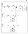
- FIG. 8 is a functional block diagram showing the configuration of the radio station 100.
- the radio station 100 includes an antenna 110, a transmission / reception switching unit 111, a receiving unit 112, and a transmitting unit 113.
- Radio station 100 also includes antennas 114A-F, transmission / reception switching units 115A-F, reception units 116A-F, and transmission units 117A-F.
- the radio station 100 includes a data signal demodulation / decoding unit 118, a control signal demodulation / decoding unit 119, a reception quality calculation unit 120, a channel estimation unit 121, and a scheduler 122.
- the radio station 100 also includes a data signal generation unit 123, a data signal encoding / modulation unit 124, a control signal generation unit 125, a control signal encoding / modulation unit 126, a reference signal generation unit 127, and an allocation arrangement. Part 128.
- Each component 110 to 113, 118 to 128 is included in the control unit 102A to F.
- Each component 114A-F, 115A-F, 116A-F, 117A-F is included in remote units 102A-F.
- Each of these components is connected so that signals and data can be input and output in one direction or in both directions. Further, the details of the respective constituent parts 114A to F, 115A to F, 116A to F, and 117A to F of the remote unit are the same as those of the respective constituent parts 110 to 113 of the control unit.
- the transmission / reception switching unit 111 switches between transmission and reception of the transmission / reception antenna 110.
- the signal output from the transmission unit 113 is transmitted via the antenna 110.
- a signal received via the antenna 110 is input to the reception unit 112.
- the antenna may be separated for transmission and reception. Further, a plurality of antennas may be provided.
- the receiving unit 112 receives an uplink signal via, for example, an uplink data channel or a control channel.
- Channels for receiving signals include PRACH (Physical Random Access CHannel), PUSCH (Physical Uplink Shared CHannel), and PUCCH (Physical Uplink Control CHannel).
- the uplink signal includes a reference signal RS (Reference Signal) for estimating the propagation state, a control signal, and a data signal.
- the control signal includes, for example, a random access signal as a signal for establishing a connection. Random access is a procedure for transmitting data from one wireless communication device (for example, a wireless terminal) to the other wireless communication device (for example, a wireless station) from a state where wireless resources used for data transmission are not allocated. It is.
- the radio station 100 establishes a connection with the radio terminal by receiving the random access signal.
- the channel estimation unit 121 extracts an RS signal included in the uplink signal, estimates a propagation state based on the received RS signal, and calculates a channel estimation value.
- the RS signal includes, for example, DM-RS (DeModulation RS).
- the channel estimation value is input to data signal demodulation / decoding section 118, control signal demodulation / decoding section 119, and reception quality calculation section 120.
- the control signal demodulation / decoding unit 119 uses the channel estimation value to demodulate and decode the control signal included in the uplink signal, and extracts control information. For example, the control signal demodulation / decoding unit 119 extracts a random access preamble from the received random access signal (RACH signal). The control signal demodulation / decoding unit 119 outputs control information related to decoding / demodulation of the data signal among the extracted control information to the data signal demodulation / decoding unit 118. The control signal demodulation / decoding unit 119 outputs control information related to scheduling among the extracted control information to the scheduler 122.
- RACH signal random access signal
- the data signal demodulation / decoding unit 118 demodulates and decodes the data signal included in the uplink signal using the control information and the channel estimation value, and extracts data. For example, decoding is performed using a PUSCH channel estimation value estimated using a reference signal.
- the data signal demodulation / decoding unit 118 outputs ACK (ACKnowledgement) / NACK (Negative ACKnowledgement) to the scheduler 122 as a decoding result of the data signal.
- the reception quality calculation unit 120 calculates reception quality based on the channel estimation value.
- the calculated reception quality is output to the scheduler 122.
- the scheduler 122 outputs a signal generation request to the data signal generation unit 123, the control signal generation unit 125, and the reference signal generation unit 127 using ACK / NACK, control information, reception quality, and the like. Further, the scheduler 122 outputs allocation information to the allocation / arrangement unit 128.
- the data signal generator 123 generates a data signal from the transmission data stored in the transmission buffer or the like based on the data signal generation request.
- the data to be transmitted includes, for example, data notified from the host device and data transferred from other radio stations.
- the data signal encoding / modulation unit 124 encodes and modulates the data signal using a predetermined parameter, and outputs the data signal to the allocation / arrangement unit 128.
- the control signal generator 125 generates a control signal to be transmitted based on the control signal generation request.
- the control signal generation unit 125 generates a random access response RAR (Random Access Response) as a response signal for establishing a connection based on the reception result of the random access signal.
- RAR Random Access Response
- the control signal generation unit 125 generates an MIB (Master Information Block) or an SIB (System Information Block) that stores system information.
- the system information includes, for example, information on reference signals for each cell, information on reference signals for each node, reference signals for each cell, reference signals for each node, and parameters for setting uplink transmission power.
- the control signal encoding / modulating unit 126 encodes and modulates the control signal using a predetermined parameter, and outputs the modulated control signal to the assigning / arranging unit 128.
- the reference signal generation unit 127 generates a reference signal to be transmitted based on the reference signal generation request and outputs the reference signal to the allocation / arrangement unit 128.
- the downlink reference signal includes a reference signal for each cell and a reference signal for each node.
- the downlink reference signal includes, for example, downlink CRS (Cell-specific Reference Signal) and downlink CSI-RS (Channel State Information Reference Signal).
- CSI-RS is used to measure downlink communication quality and can be set for each node.
- the CRS is used for measurement of downlink communication quality and demodulation of downlink signals, and is set in association with cell identification information (cell ID).
- the system information includes, for example, CSI-RS Config information indicating the configuration of CSI-RS as information related to the reference signal for each node.
- the allocation / arrangement unit 128 allocates the generated data signal, control signal, and reference signal to a predetermined radio resource of a predetermined channel based on the allocation information, and arranges the data signal, control signal, and reference signal.
- the data is output to a predetermined transmission unit.
- the allocation / arrangement unit 128 allocates a signal including broadcast information to a broadcast channel PBCH (Physical Broadcast CHannel) or a shared channel PDSCH (Physical Downlink Shared CHannel) in which radio resources are specified by the broadcast channel. Further, the allocation / arrangement unit 128 allocates CRS and CSI-RS to PDCCH (Physical Downlink Control Down CHannel) and E-PDCCH (Enhanced Down-Physical Downlink Control Down CHannel).
- PBCH Physical Broadcast CHannel
- PDSCH Physical Downlink Shared CHannel
- FIG. 9 is a functional block diagram showing the configuration of the wireless terminal 103.
- the wireless terminal 103 includes a transmission / reception antenna 130, a transmission / reception switching unit 131, a reception unit 132, and a transmission unit 133.
- the wireless terminal 103 includes 20, a transmission unit 21, a reception unit 22, and a control unit 23.
- Radio terminal 103 also includes data signal demodulation / decoding section 134, control signal demodulation / decoding section 135, reception quality calculation section 136, and channel estimation section 137.
- the radio terminal 103 also includes a data signal generation unit 138, a control signal generation unit 140, a data signal encoding / modulation unit 139, a control signal encoding / modulation unit 141, a reference signal generation unit 142, and a RACH signal.
- a generation unit 143, a RACH signal encoding / modulation unit 144, an allocation / arrangement unit 145, and a transmission power determination unit 146 are provided. Each of these components is connected so that signals and data can be input and output in one direction or in both directions.
- the functional configuration and hardware configuration of the wireless terminals 104 and 105 are the same as the functional configuration and hardware configuration of the wireless terminal 103.
- the transmission / reception switching unit 131 switches between transmission and reception of the transmission / reception antenna 130.
- a signal output from the transmission unit 133 is transmitted via the antenna 131.
- a signal received via the antenna 130 is input to the reception unit 132.
- the antenna may be separated for transmission and reception. Further, a plurality of antennas may be provided.
- the receiving unit 132 receives a downlink signal via, for example, a downlink data channel or a control channel.
- Channels that receive signals include, for example, PBCH, PDCCH, and PDSCH.
- the downlink signal includes an RS signal for measurement and demodulation, a control signal, and a data signal.
- the control signal includes a signal for establishing synchronization and a response signal for establishing connection.
- the control signal includes MIB and SIB.
- the channel estimation unit 137 extracts an RS signal included in the downlink signal, estimates a propagation state based on the received RS signal, and calculates a channel estimation value.
- the RS signal includes, for example, CRS and CSI-RS.
- the channel estimation value is input to data signal demodulation / decoding section 134, control signal demodulation / decoding section 135, and reception quality calculation section 136.
- the control signal demodulation / decoding unit 135 demodulates and decodes the control signal included in the downlink signal using the channel estimation value, and acquires control information. For example, the control signal demodulation / decoding unit 135 acquires CSI-RS Config information stored in the received SIB. The control signal demodulation / decoding unit 135 outputs control information related to decoding / demodulation of the data signal among the acquired control information to the data signal demodulation / decoding unit 134. Further, the control signal demodulation / decoding unit 135 outputs allocation information regarding allocation / arrangement among the extracted control information to the allocation / arrangement unit 145.
- the data signal demodulation / decoding unit 134 demodulates and decodes the data signal included in the downlink signal using the control information and the channel estimation value, and acquires data.
- the data signal demodulator / decoder 134 outputs ACK (ACKnowledgement) / NACK (Negative ACKnowledgement) to the control signal generator 140 as a result of decoding the data signal.
- the reception quality calculation unit 136 calculates reception quality based on the channel estimation value.
- the reception quality includes, for example, SIR, SINR, RSRP, and RSRQ.
- the calculated reception quality is output to the control signal generation unit 140.
- the data signal generator 138 generates a data signal from transmission data stored in a transmission buffer or the like.
- the data signal encoding / modulation unit 139 encodes and modulates the data signal using a predetermined parameter, and outputs the data signal to the allocation / arrangement unit 145.
- the control signal generator 140 generates a control signal to be transmitted based on ACK / NACK, control information, reception quality, and the like.
- the control signal encoding / modulating unit 141 encodes and modulates the generated control signal using predetermined parameters, and outputs the modulated control signal to the assigning / arranging unit 145.
- the reference signal generation unit 142 generates a reference signal to be transmitted and outputs it to the allocation / arrangement unit 145.
- the RACH signal generation unit 143 selects a random access preamble based on the control information, and generates a RACH (Random Access CHannel) signal as a signal for establishing a connection.
- RACH Random Access CHannel
- the RACH signal encoding / modulating unit 144 encodes and modulates the generated RACH signal and outputs it to the allocation / arrangement unit 145.
- the allocation / arrangement unit 145 allocates and allocates the generated data signal, control signal, reference signal, and RACH signal to a predetermined radio resource of a predetermined channel based on the allocation information, and sends it to the transmission unit 133. Output.
- the allocation / allocation unit 145 allocates signals to, for example, PUSCH, PRACH, and PUCCH as uplink physical channels.
- the transmission power control unit 146 controls uplink transmission power based on control information and reception quality. Specifically, the transmission power control unit 146 calculates a path loss using the reference transmission power notified from the radio station 100 as control information and the reception quality. Then, the transmission power control unit 146 calculates the initial transmission power using the maximum transmission power of the wireless terminal 103, the initial transmission power calculation parameter that is previously notified and acquired from the wireless station 100, and the path loss.
- the hardware configuration of the radio station 100 in the radio communication system 90 according to the second embodiment is the same as the hardware configuration of the radio station 4 of FIG.
- Each component 110 to 113, 114A to F, 115A to F, 116A to F, and 117A to F of the radio station 100 is realized by an integrated circuit such as an antenna, an RF circuit, and a DSP.
- Each component 118 to 128 of the radio station 100 is realized by an integrated circuit such as a CPU, for example.
- the hardware configuration of the wireless terminal 103 in the wireless communication system 90 according to the second embodiment is the same as the hardware configuration of the mobile terminal 7 in FIG.
- Each component 130 to 133 of the wireless terminal 103 is realized by, for example, an antenna, an RF circuit, and a DSP.
- Each component 134 to 145 of the radio station 100 is realized by an integrated circuit such as a CPU, for example.
- FIG. 10 is a sequence diagram for explaining an operation related to connection establishment of the wireless communication system 90.
- the wireless terminal 103 located in the cell C 100 is in a state where connection with the wireless station 100 has not been established, and an operation of establishing connection between the wireless station 100 and the wireless terminal 103 will be described as an example.
- the radio station 103 broadcasts SIB Type 1 to Type 14 as system information in the cell C100 (S11).
- SIB Type 14 is included in SIB Type 14.
- the wireless terminal 103 receives SIB Type 1 to Type 14 broadcast in the cell C1. Since the CSI-RS Config information is broadcasted as SIB TypeSI14 in the cell C100, the wireless terminal 103 located in the cell C100 can acquire the CSI-RS Config information before establishing the connection.
- the CSI-RS ⁇ Config information includes, for example, the number of antenna ports that transmit CSI-RS, CSI-RS signal generation information, reference transmission power corresponding to CSI-RS, and the like.
- the radio station 100 transmits reference signals CSI-RS # 1 to CSI-RS #n associated with each node (S12). Thereby, different RS signals are transmitted between the control unit 101 and the remote units 120A to 120F.
- the remote units 120A to 120F of the radio station 100 transmit reference signals CSI-RS assigned to the remote units 120A to 120F, respectively, and the control unit 101 of the radio station 100 transmits the reference signals CRS assigned to the entire cell. May be sent. Also in this case, the RS signal is different for each node.
- the wireless terminal 103 separates the received signal using the CSI-RS Config information, and acquires the reception quality (reception level for each node) for each node (S13).
- the wireless terminal 14 uses the reception quality of each node, and a reference transmit power P 0 for each node, and calculates the path loss PL C of each node (S14).
- Path loss PL C is calculated for example by the following equation (1).
- PL C (n) P 0 (n)-RSRP (n) (1)
- P 0 (n) the node reference transmission power of n
- RSRP (n) is CSI-RS #n assigned to the node n Reception quality.
- the wireless terminal 103 uses the path loss PL C of each calculation node, calculates the initial transmission power of the random access signal (S15).
- Initial transmission power is determined so as to compensate for example path loss PL C.
- the initial transmission power is calculated based on the following equation (2).
- P PRACH (n) min ⁇ P CMAX, C (i), PREAMBLE_RECEIVED_TARGET_POWER (n) + PL C (n) ⁇ (2)
- P PRACH (n) is the initial transmission power of PRACH from wireless terminal 103 to node n
- P CMAX, C (i) is the maximum transmission power of wireless terminal 103
- PPREAMBLE_RECEIVED_TARGET_POWER (n) is the power target value of node n
- PL C (n) is the path loss of the node n.
- the wireless terminal 103 transmits a random access signal for each node using the calculated PRACH initial transmission power.
- the wireless terminal 103 selects a set of nodes that transmit a random access signal among a plurality of nodes based on CSI-RS Config information and reception quality for each node, and randomly accesses each selected node.
- a signal is transmitted (S16).
- the radio station 100 transmits a random access response RAR in response to the reception of the random access signal by the control unit 101 and the remote units 120A to 120F (S17). Then, the wireless terminal 103 receives a random access response RAR for each node. At this time, the radio station 100 selects a set of nodes for continuing connection establishment from a plurality of nodes according to the reception level of the random access signal received for each node, and connects to each selected node. A response for establishment may be transmitted.
- connection establishment and cooperative communication establishment are completed between the radio station 100 and the radio terminal 103 (S18). Thereby, for example, communication of control information and data via the dedicated channel is performed between the remote unit 102A of the wireless station 100 and the wireless terminal 103.
- FIG. 12 is a flowchart for explaining an operation related to connection establishment of the wireless communication system according to the third embodiment.
- the overall configuration of the wireless communication system according to the third embodiment is the same as the configuration of the wireless communication system 90 of FIG.
- the wireless communication system according to the third embodiment includes a wireless terminal that is not capable of CoMP communication and a second wireless terminal that is not capable of CoMP communication.
- the radio station according to the third embodiment is different from the radio station 100 according to the second embodiment in operations related to the control signal generation unit 125.
- the control signal generator 125 generates a control signal including control information for wireless terminals capable of cooperative communication and control information for wireless terminals not capable of cooperative communication.
- a parameter for calculating the transmission power of a random access signal a parameter PREAMBLE_RECEIVED_TARGET_POWER for wireless terminals that are not capable of CoMP communication and a parameter PREAMBLE_RECEIVED_TARGET_POWER_2 for wireless terminals capable of CoMP communication are included in the control signal.
- PREAMBLE_RECEIVED_TARGET_POWER is included in any of SIB Type # 1 to # 13
- PREAMBLE_RECEIVED_TARGET_POWER_2 is included in SIB Type # 14.
- SIB Type # 14 is a control signal that can be identified by a wireless terminal capable of CoMP communication and cannot be identified by a second wireless terminal that is not capable of CoMP communication.
- the parameter PREAMBLE_RECEIVED_TARGET_POWER is a target value of transmission power, and can be calculated using the following equation (3), for example.
- PREAMBLE_RECEIVED_TARGET_POWER preambleInitialReceivedTargetPower + DELTA_PREAMBLE + (PREAMBLE_TRANSMISSION_COUNTER- 1) * powerRampingStep (3)
- preambleInitialReceivedTargetPower is a parameter that can be set in increments of 2 [dBm], for example, in the range of -120 to -90 [dBm].
- DELTA_PREAMBLE is a parameter depending on the format of the preamble, for example, and can be set in three ways: ⁇ 0, ⁇ 3, 8 ⁇ [dBm].
- PREAMBLE_TRANSMISSION_COUNTER is a preamble transmission counter
- powerRampingStep is a ramping width of transmission power control.
- PREAMBLE_RECEIVED_TARGET_POWER and PREAMBLE_RECEIVED_TARGET_POWER_2 are calculated by setting different values for preambleInitialReceivedTargetPower, for example.
- PREAMBLE_RECEIVED_TARGET_POWER is set to a value adjusted assuming that a path loss is calculated for each cell.
- PREAMBLE_RECEIVED_TARGET_POWER_2 is set to a value assuming that a path loss is calculated for each node.
- PREAMBLE_RECEIVED_TARGET_POWER and PREAMBLE_RECEIVED_TARGET_POWER_2 may be calculated by, for example, a higher-level device and notified to the radio station 100, or may be calculated by the radio station 100.
- radio station 100 of FIG. 9 of the second embodiment Other configurations and operations of the radio station according to the third embodiment are the same as those of the radio station 100 of FIG. 9 of the second embodiment.
- the hardware configuration of the radio station according to the third embodiment is the same as the hardware configuration of the radio station 100 according to the second embodiment.
- the wireless terminal according to the third embodiment is different from the wireless terminal 103 according to the second embodiment in operations related to the control signal demodulation / decoding unit 135 and the transmission power determination unit 146.
- the control signal demodulation / decoding unit 135 demodulates and decodes the SIB, and when SIB Type # 14 is identified, sets PREAMBLE_RECEIVED_TARGET_POWER_2 as a parameter used by the transmission power determination unit 146 instead of PREAMBLE_RECEIVED_TARGET_POWER. When SIB Type # 14 is not identified, PREAMBLE_RECEIVED_TARGET_POWER is set as it is. Then, the transmission power determination unit 146 calculates the initial transmission power of the random access signal by using the set parameter, for example, by the above-described equation (2).
- the second wireless terminal according to the third embodiment is a wireless terminal that is not capable of CoMP communication, and the control signal demodulation / decoding unit does not identify SIB ⁇ Type # 14, and the second wireless terminal establishes connection. Is first executed for each cell.
- Other configurations and operations are the same as those of the wireless terminal 103 of the second embodiment.
- the hardware configuration of the second wireless terminal according to the third embodiment is the same as the hardware configuration of the wireless terminal 103 of the second embodiment.
- FIG. 12 is a flowchart for explaining an operation related to connection establishment of the wireless communication system according to the third embodiment.
- SIB Type # 14 includes PREAMBLE_RECEIVED_TARGET_POWER_2.
- wireless terminal of 3rd Embodiment receives the alerted
- the wireless terminal according to the third embodiment determines whether or not SIB Type 14 has been identified (S31). If the determination result in S31 is YES, the wireless terminal is capable of CoMP communication, and the wireless terminal according to the third embodiment receives CSI RS # 1 to #n as in S12 of FIG. Similarly to S13, the reception level for each node is calculated (S32). Next, the wireless terminal according to the third embodiment sets PREAMBLE_RECEIVED_TARGET_POWER_2 as a parameter for calculating transmission power (S33). In this way, a target value is set assuming that a path loss is calculated for each node.
- the wireless terminal according to the third embodiment calculates a path loss for each node as in S14 of FIG. 10 (S34).
- the wireless terminal according to the third embodiment determines the initial transmission power of the PRACH for each node using PREAMBLE_RECEIVED_TARGET_POWER_2 (S35).
- wireless terminal of 3rd Embodiment transmits PRACH for every node similarly to S16 of FIG. 10 using the determined initial transmission power (S36). Thereby, connection establishment and cooperative communication establishment are performed.
- the second wireless terminal is not capable of CoMP communication, and the second wireless terminal of the third embodiment receives CSI RS # 1 to #n and Considering RS, the reception level is calculated (S37).
- the second wireless terminal according to the third embodiment sets PREAMBLE_RECEIVED_TARGET_POWER as a parameter for calculating transmission power (S38). In this way, a target value adjusted assuming that a path loss is calculated for each cell is set.
- the second wireless terminal of the third embodiment calculates a path loss for each cell (S39).
- wireless terminal of 3rd Embodiment determines the initial transmission power of PRACH for every cell using PREAMBLE_RECEIVED_TARGET_POWER (S40). At this time, by using the adjusted target value, a path loss error can be compensated and a highly accurate value can be calculated. And the 2nd radio
- FIG. 13 is a flowchart for explaining the operation of the wireless communication system according to the fourth embodiment.
- the overall configuration of the wireless communication system according to the fourth embodiment is the same as the configuration of the wireless communication system 90 of FIG.
- the radio station according to the fourth embodiment is different from the radio station 100 according to the second embodiment in operations related to the scheduler 122 and the allocation / arrangement unit 128.
- the radio station transmits radio resource information (RRC signal) as higher layer control information via an individual channel after connection establishment.
- RRC radio resource information
- the scheduler 122 stores an RRC (Radio Resource Control) signal when allocating the RRC signal to the channel.
- RRC Radio Resource Control
- the allocation information is set so that other control information allocated to other spaces is allocated to the space allocated to CSI-RS Config information, and the other control information is repeated.
- the allocation / arrangement unit 128 repeats and arranges other control information for transmission.
- the allocation / arrangement unit 128 allocates other control information to the space allocated to the CSI-RS Config information together with flag information indicating that other control information is being replicated.
- the size of CSI-RS Config information is, for example, about 44 bits.
- radio station 100 of FIG. 9 of the second embodiment Other configurations and operations of the radio station according to the fourth embodiment are the same as those of the radio station 100 of FIG. 9 of the second embodiment.
- the hardware configuration of the radio station according to the fourth embodiment is the same as the hardware configuration of the radio station 100 according to the second embodiment.
- the wireless terminal according to the fourth embodiment is different from the wireless terminal 103 according to the second embodiment in operations related to the control signal demodulation / decoding unit 135.
- the control signal demodulation / decoding unit 135 demodulates and decodes the RRC signal to obtain radio resource information. At this time, control information is acquired based on flag information indicating that repetition is being performed.
- FIG. 13 is a flowchart for explaining the operation of the wireless communication system according to the fourth embodiment.
- SIB Type # 14 including CSI-RS Config information is transmitted from the radio station as in S11 of FIG. 10 of the second embodiment, and connection establishment is executed as in S12 to S18. Connection establishment is complete.
- the radio station of the fourth embodiment determines whether the CSI-RS Config information has been broadcast (S50).
- the radio station according to the fourth embodiment arranges CSI-RS Config information in the RRC signal storage space (S55). Then, the radio station according to the fourth embodiment transmits an RRC signal (S54). Thereby, CSI-RS Config information is notified.
- the radio station of the fourth embodiment selects control information to be repeated (S51).
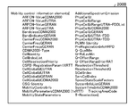
- Lists 200A to 200C in FIGS. 14 to 16 show examples of candidate lists of control signals to which CSI-RS-Config information is assigned and are repeated in space.
- candidate control signals are included in, for example, Radio resource control information information elements, Security control information elements, Mobility control information elements, Measurement information elements, Other information elements, MBMS information elements, etc. Each control signal is mentioned.
- the radio station according to the fourth embodiment selects a control signal to be repeated in the space to which the CSI-RS Config information has been allocated from the control signal candidate list, and sets the control signal in the allocation information.
- the radio station generates flag information indicating that the station is in repetition (S52).
- the radio station stores the selected control signal together with the flag information in the space where the CSI-RS Config information has been assigned (S53).
- the radio station of the fourth embodiment transmits an RRC signal (S54).
- the transmitted RRC signal is received by the radio terminal according to the fourth embodiment, and the replicated control information is acquired based on the flag information.
- the fourth embodiment it is possible to improve transmission control characteristics in a wireless communication system that performs CoMP communication. Furthermore, the reliability of other control signals can be improved by repeating and transmitting other control signals using the RRC signal of the higher layer control information.
- transmission is performed at a later timing than the CSI-RS Config information to the space allocated to the CSI-RS Config information in the space where the radio resource information of the upper layer control information is stored.
- a control signal to be transmitted may be assigned and transmitted.
- a list 210 of FIG. 17 shows an example of a candidate list of control signals transmitted at a timing after the CSI-RS Config information.
- the scheduler 122 selects a control signal to be allocated to the space to which the CSI-RS Config information has been allocated from the control signal candidate list transmitted at a timing later than the CSI-RS Config information, and assigns it to the allocation information. Set.
- the allocation / arrangement unit 128 allocates the selected control signal based on the allocation information, and transmits the selected control signal in the space where the CSI-RS ⁇ Config information has been allocated.
- the allocation / arrangement unit 128 allocates the selected control signal based on the allocation information, and transmits the selected control signal in the space where the CSI-RS ⁇ Config information has been allocated.
- this makes it possible to advance the transmission timing of the selected control signal.
- the wireless communication systems of the first to fourth embodiments can be realized as, for example, an LTE-A system.
- the present invention can also be applied to a wireless communication system using a communication method other than LTE-A.
- the first to fourth embodiments can be applied to mobile terminals such as mobile phones, smartphones, and PDAs (Personal Digital Assistants) as wireless terminals.
- the first to fourth embodiments can be applied to various communication devices that communicate with a base station such as a mobile relay station.
- first to fourth embodiments can be applied to base stations of various scales such as macro base stations and femto base stations as radio stations.
- first to fourth embodiments can be applied to various communication devices that communicate with mobile stations such as relay stations.
- each component of the radio station and radio terminal is not limited to the mode of the first to fourth embodiments, and all or a part thereof can be used for various loads, usage conditions, etc. Accordingly, it may be configured to be functionally or physically distributed / integrated in an arbitrary unit.
- the memory may be connected via a network or a cable as an external device of a wireless station or a wireless terminal.
Landscapes
- Engineering & Computer Science (AREA)
- Computer Networks & Wireless Communication (AREA)
- Signal Processing (AREA)
- Mobile Radio Communication Systems (AREA)
Abstract
The objective of the disclosed technique, which has been contrived in view of the above, is to provide a wireless communication method, a wireless communication system, a radio station and a radio terminal wherein the transmission control characteristic can be improved in coordinated multipoint communication. According to a wireless communication method for use in a wireless communication system in which a single cell includes a plurality of nodes and which has a radio terminal capable of performing coordinated communications with one or more nodes, the cell notifies the radio terminal of information related to a reference signal of each of the plurality of nodes before establishing a connection to the radio terminal, and the radio terminal transmits a signal, which is to be used to establish a connection, by use of a parameter that is in accordance with the communication quality of each of the plurality of nodes acquired by using the information related to the reference signal of each of the plurality of nodes.
Description
本発明は、無線通信方法、無線通信システム、無線局、及び無線端末に関する。
The present invention relates to a wireless communication method, a wireless communication system, a wireless station, and a wireless terminal.
近年、携帯電話システム等の無線通信システムにおいて、無線通信の更なる高速化・大容量化等を図るため、次世代の無線通信技術について議論が行われている。例えば、標準化団体である3GPP(3rd Generation Partnership Project)では、LTE(Long Term Evolution)と呼ばれる通信規格や、LTEの無線通信技術をベースとしたLTE-A(LTE - Advanced)と呼ばれる通信規格が提案されている。
In recent years, next-generation wireless communication technologies have been discussed in order to further increase the speed and capacity of wireless communication in wireless communication systems such as mobile phone systems. For example, 3GPP (3rd Generation Partnership Project), a standardization organization, proposes a communication standard called LTE (Long Term Evolution) and a communication standard called LTE-A (LTE-Advanced) based on LTE wireless communication technology. Has been.
LTE-Aシステム等において、セル間干渉の低減や受信信号強度の改善のため、多地点協調(Coordinated MultiPoint、以下、CoMPともいう。)通信が検討されている。多地点協調通信では、地理的に離れた複数のポイント(以下、ノードともいう。)が協調して通信を行う。各ポイントは、例えば、基地局、通信ユニット、アンテナ或いはこれらにより形成されるセルに相当する。これにより、多地点間での送信あるいは受信のダイナミックな調整が行われる。例えば、下りリンクの多地点協調通信では、複数のポイントから無線端末へ結合送信する方法が検討されている。また、例えば、上りリンクの多地点協調通信では、複数のポイントで受信された信号をポイント間で通信しながら結合処理する方法が検討されている。
In the LTE-A system and the like, coordinated multipoint (hereinafter also referred to as CoMP) communication is being studied in order to reduce inter-cell interference and improve received signal strength. In multipoint cooperative communication, a plurality of geographically separated points (hereinafter also referred to as nodes) perform communication in cooperation. Each point corresponds to, for example, a base station, a communication unit, an antenna, or a cell formed by these. Thereby, dynamic adjustment of transmission or reception between multiple points is performed. For example, in downlink multipoint cooperative communication, a method of jointly transmitting a plurality of points to a wireless terminal has been studied. Also, for example, in uplink multipoint cooperative communication, a method of combining signals received at a plurality of points while communicating between the points has been studied.
しかしながら、多地点協調通信によりポイント間干渉の低減や受信信号強度の改善を実現するためには、制御の遅延やシグナリングの増大の考慮のもとで、ポイント間での適切な調整が必要である。例えば多地点協調通信では、多様な種類の複数のポイントとの間で無線端末が通信を行うことが想定される。このとき、例えば無線端末から各ポイントへの送信パラメータが適切に制御されないと、ポイント間干渉の低減等を阻害する恐れがある。
However, in order to reduce inter-point interference and improve received signal strength through multipoint coordinated communication, appropriate adjustments between points are necessary in consideration of control delay and increased signaling. . For example, in multipoint cooperative communication, it is assumed that a wireless terminal communicates with a plurality of various types of points. At this time, for example, if the transmission parameter from the wireless terminal to each point is not properly controlled, there is a possibility that the reduction of inter-point interference may be hindered.
開示の技術は、上記に鑑みてなされたものであって、多地点協調通信において、送信制御特性を向上することのできる無線通信方法、無線通信システム、無線局、及び無線端末を提供することを目的とする。
The disclosed technology has been made in view of the above, and provides a wireless communication method, a wireless communication system, a wireless station, and a wireless terminal capable of improving transmission control characteristics in multipoint cooperative communication. Objective.
上述した課題を解決し、目的を達成するために、本件の開示する無線通信方法は、1つのセルが複数のノードを含み、1以上のノードとの協調通信が可能な無線端末を有する無線通信システムにおける無線通信方法であって、前記セルで、前記無線端末との接続確立の前に、前記ノード毎の参照信号に関する情報を前記無線端末に通知し、前記無線端末で、前記ノード毎の参照信号に関する情報を用いて取得されるノード毎の通信品質に応じたパラメータで、前記接続確立のための信号を送信する、ことを特徴とする。
In order to solve the above-described problems and achieve the object, a wireless communication method disclosed in the present application is a wireless communication including a wireless terminal in which one cell includes a plurality of nodes and capable of cooperative communication with one or more nodes. A wireless communication method in a system, wherein, in the cell, before establishing a connection with the wireless terminal, information on a reference signal for each node is notified to the wireless terminal, and the wireless terminal refers to the node for each node. A signal for establishing the connection is transmitted with a parameter corresponding to the communication quality of each node acquired using information related to the signal.
本件の開示する無線通信装置の一つの態様によれば、多地点協調通信において、送信制御特性を向上することができるという効果を奏する。
According to one aspect of the wireless communication device disclosed in the present case, there is an effect that transmission control characteristics can be improved in multipoint cooperative communication.
以下に、本件の開示する無線通信方法、無線通信システム、無線局、及び無線端末の実施例を、図面を参照しながら説明する。なお、以下の実施例により本件の開示する無線通信方法、無線通信システム、無線局、及び無線端末が限定されるものではない。
[第1実施形態]
図1は、第1実施形態に係る無線通信システム1の構成を示す。図1に示すように、無線通信システム1は、無線局4と、無線端末7,8とを有する。無線局4は、有線接続を介して上位装置3と接続されており、上位装置3は、有線接続を介してネットワーク2に接続されている。 Embodiments of a wireless communication method, a wireless communication system, a wireless station, and a wireless terminal disclosed herein will be described below with reference to the drawings. Note that the wireless communication method, the wireless communication system, the wireless station, and the wireless terminal disclosed in the present application are not limited by the following embodiments.
[First Embodiment]
FIG. 1 shows a configuration of awireless communication system 1 according to the first embodiment. As shown in FIG. 1, the wireless communication system 1 includes a wireless station 4 and wireless terminals 7 and 8. The radio station 4 is connected to the host device 3 via a wired connection, and the host device 3 is connected to the network 2 via a wired connection.
[第1実施形態]
図1は、第1実施形態に係る無線通信システム1の構成を示す。図1に示すように、無線通信システム1は、無線局4と、無線端末7,8とを有する。無線局4は、有線接続を介して上位装置3と接続されており、上位装置3は、有線接続を介してネットワーク2に接続されている。 Embodiments of a wireless communication method, a wireless communication system, a wireless station, and a wireless terminal disclosed herein will be described below with reference to the drawings. Note that the wireless communication method, the wireless communication system, the wireless station, and the wireless terminal disclosed in the present application are not limited by the following embodiments.
[First Embodiment]
FIG. 1 shows a configuration of a
無線局4は、制御ユニット9と、遠隔ユニット5,6とを有する。制御ユニット9は、例えばeNodeB(evolved Node B)として実現できる。また、遠隔ユニット5,6は、例えばeNodeBが有するRRH(Remote Radio Head)として実現できる。制御ユニット9、遠隔ユニット5、及び遠隔ユニット6はそれぞれアンテナ(ポイント)を有し、互いに離れた地点に配設される。制御ユニット9及び遠隔ユニット5,6がそれぞれノードに相当する。制御ユニット9はセルC1を形成し、遠隔ユニット5,6はそれぞれセルC1と重なるカバーエリアR1,R2を形成している。無線端末7,8は、セルC1に在圏している。このとき、無線端末7はカバーエリアR1に含まれている。
The radio station 4 has a control unit 9 and remote units 5 and 6. The control unit 9 can be realized as eNodeB (evolved (Node B), for example. Further, the remote units 5 and 6 can be realized as, for example, RRH (Remote Radio Radio Head) included in the eNodeB. The control unit 9, the remote unit 5, and the remote unit 6 each have an antenna (point) and are arranged at points separated from each other. The control unit 9 and the remote units 5 and 6 correspond to nodes. The control unit 9 forms a cell C1, and the remote units 5 and 6 form cover areas R1 and R2 that overlap the cell C1, respectively. The wireless terminals 7 and 8 are located in the cell C1. At this time, the wireless terminal 7 is included in the cover area R1.
制御ユニット9及び遠隔ユニット5,6は、有線接続を介して互いに通信を行うと共に、無線端末7,8に対してCoMP通信を行う。例えば、無線端末7との下りリンクのCoMP通信では、制御ユニット9及び遠隔ユニット5,6のうち下りリンクのCoMP通信で使用するセットとして選択される1以上のノードから、無線端末7に、データを結合送信する。また、例えば、無線端末7との上りリンクのCoMP通信では、制御ユニット9及び遠隔ユニット5,6のうち上りリンクのCoMP通信で使用するセットとして選択される1以上のノードで、無線端末7からのデータを受信し、受信信号をノード間で合成する。
The control unit 9 and the remote units 5 and 6 communicate with each other via a wired connection and also perform CoMP communication with the wireless terminals 7 and 8. For example, in downlink CoMP communication with the radio terminal 7, data is transmitted from one or more nodes selected as a set to be used for downlink CoMP communication among the control unit 9 and the remote units 5 and 6 to the radio terminal 7. Send the combined. Further, for example, in uplink CoMP communication with the radio terminal 7, one or more nodes selected as a set to be used for uplink CoMP communication among the control unit 9 and the remote units 5 and 6 are transmitted from the radio terminal 7. Are received, and the received signal is synthesized between the nodes.
図2は、無線局4の構成を示す機能ブロック図である。図2に示すように、無線局4の制御ユニット9は、アンテナ10と、送信部11と、受信部12と、制御部13とを備える。また、無線局4の遠隔ユニット5は、アンテナ14と、送信部15と、受信部16とを備え、無線局4の遠隔ユニット6は、アンテナ17と、送信部18と、受信部19とを備える。これら各構成部分は、一方向又は双方向に、信号やデータの入出力が可能なように接続されている。なお、遠隔ユニット5,6の各構成部分14~19は、制御ユニット9の各構成部分アンテナ14~16と同様である。
FIG. 2 is a functional block diagram showing the configuration of the wireless station 4. As shown in FIG. 2, the control unit 9 of the wireless station 4 includes an antenna 10, a transmission unit 11, a reception unit 12, and a control unit 13. The remote unit 5 of the wireless station 4 includes an antenna 14, a transmission unit 15, and a reception unit 16. The remote unit 6 of the wireless station 4 includes an antenna 17, a transmission unit 18, and a reception unit 19. Prepare. Each of these components is connected so that signals and data can be input and output in one direction or in both directions. The constituent parts 14 to 19 of the remote units 5 and 6 are the same as the constituent antennas 14 to 16 of the control unit 9.
送信部11は、データ信号や制御信号を、アンテナ11を介して送信する。送信する信号は例えば、セル毎の参照信号に関する情報、ノード毎の参照信号に関する情報、セル毎の参照信号、ノード毎の参照信号、及び上り送信電力を設定するためのパラメータを含む。
The transmission unit 11 transmits data signals and control signals via the antenna 11. The signal to be transmitted includes, for example, information on a reference signal for each cell, information on a reference signal for each node, a reference signal for each cell, a reference signal for each node, and a parameter for setting uplink transmission power.
受信部12は、無線端末7,8から送信されたデータ信号や制御信号を、アンテナ11を介して受信する。受信する信号は例えば、接続を確立するための信号を含む。なお、アンテナ11は送信と受信で別体としてもよい。
The receiving unit 12 receives data signals and control signals transmitted from the wireless terminals 7 and 8 via the antenna 11. The received signal includes, for example, a signal for establishing a connection. The antenna 11 may be separated for transmission and reception.
制御部13は、有線接続あるいは無線接続を介して、上位装置3や他の無線局から情報や信号を取得する。制御部13は、送信するデータや制御情報を送信部11,15,18に出力する。制御部13は、受信されるデータや制御情報を受信部12,16,19から入力する。例えば、制御部13は、システム情報をセルC1で報知させる。システム情報は例えば、報知チャネル又は報知チャネルで指定される共有チャネルで報知される。システム情報は例えば、セル毎の参照信号に関する情報、及びノード毎の参照信号に関する情報を含む。また例えば、制御部13は、送信部11,15,18に参照信号を送信させる。このとき、送信部11は、通信品質の測定のための参照信号として、セル毎の参照信号を使用し、送信部15,18はそれぞれ、通信品質の測定のための参照信号として、遠隔ユニット5,6に対応するノード毎の参照信号を使用する。
The control unit 13 acquires information and signals from the host device 3 and other wireless stations via a wired connection or a wireless connection. The control unit 13 outputs data to be transmitted and control information to the transmission units 11, 15 and 18. The control unit 13 inputs received data and control information from the receiving units 12, 16, and 19. For example, the control unit 13 notifies the system information in the cell C1. For example, the system information is broadcast on a broadcast channel or a shared channel designated by the broadcast channel. The system information includes, for example, information related to the reference signal for each cell and information related to the reference signal for each node. For example, the control unit 13 causes the transmission units 11, 15, and 18 to transmit a reference signal. At this time, the transmission unit 11 uses a reference signal for each cell as a reference signal for measuring communication quality, and the transmission units 15 and 18 each use the remote unit 5 as a reference signal for measuring communication quality. , 6 is used as a reference signal for each node.
図3は、無線端末7の構成を示す機能ブロック図である。図3に示すように、無線端末7は、アンテナ20と、送信部21と、受信部22と、制御部23とを備える。これら各構成部分は、一方向又は双方向に、信号やデータの入出力が可能なように接続されている。無線端末8の機能的構成およびハードウェア構成は、無線端末7の機能的構成及びハードウェア構成と同様である。
FIG. 3 is a functional block diagram showing the configuration of the wireless terminal 7. As illustrated in FIG. 3, the wireless terminal 7 includes an antenna 20, a transmission unit 21, a reception unit 22, and a control unit 23. Each of these components is connected so that signals and data can be input and output in one direction or in both directions. The functional configuration and hardware configuration of the wireless terminal 8 are the same as the functional configuration and hardware configuration of the wireless terminal 7.
送信部21は、データ信号や制御信号を、アンテナ20を介して送信する。送信する信号は例えば、接続確立のための信号を含む。
The transmission unit 21 transmits a data signal and a control signal via the antenna 20. The signal to be transmitted includes, for example, a signal for establishing a connection.
受信部12は、無線端末から送信されたデータ信号や制御信号を、アンテナ20を介して受信する。受信する信号は例えば、セル毎の参照信号に関する情報、ノード毎の参照信号に関する情報、セル毎の参照信号、ノード毎の参照信号、および上り送信電力を決めるためのパラメータを含む。なお、アンテナ20は送信と受信で別体としてもよい。
The receiving unit 12 receives the data signal and the control signal transmitted from the wireless terminal via the antenna 20. The received signal includes, for example, information on a reference signal for each cell, information on a reference signal for each node, a reference signal for each cell, a reference signal for each node, and a parameter for determining uplink transmission power. The antenna 20 may be separated for transmission and reception.
制御部23は、送信するデータや制御情報を送信部21に出力する。また、制御部23は、受信部22から受信されるデータや制御情報を入力する。例えば、制御部23は、接続確立前に、受信したセル毎の参照信号に関する情報およびノード毎の参照信号に関する情報に基づいて、無線局4から送信される参照信号全体の受信信号から、ノード毎の参照信号の受信レベルを取得し、ノード毎の通信品質を取得する。制御部23は、取得したノード毎の通信品質から、接続確立のための信号の送信電力を決定する。
The control unit 23 outputs data to be transmitted and control information to the transmission unit 21. In addition, the control unit 23 inputs data and control information received from the receiving unit 22. For example, the control unit 23 determines, based on the received information on the reference signal for each cell and the information on the reference signal for each node, from the received signal of the entire reference signal transmitted from the wireless station 4 for each node before connection establishment. The reference signal reception level is acquired, and the communication quality for each node is acquired. The control unit 23 determines the transmission power of a signal for establishing a connection from the acquired communication quality for each node.
図4は、無線局4のハードウェア構成を示す図である。図4に示すように、無線局4は、ハードウェアの構成要素として、例えばアンテナ30,37,41を備えるRF回路(Radio Frequency)31,38,42と、DSP(Digital Signal Processor)32,39,43と、CPU(Central Processing Unit)34と、メモリ33,35,40,44と、ネットワークIF(Interface)36とを有する。CPU34は、スイッチ等のネットワークIF36を介して各種信号やデータの入出力が可能なように接続されている。メモリ33,35,40,44は、例えばSDRAM(Synchronous Dynamic Random Access Memory)等のRAM(Random Access Memory)、ROM(Read Only Memory)、及びフラッシュメモリの少なくともいずれかを含み、プログラムや制御情報やデータを格納する。送信部11,15,18及び受信部12,16,19は、例えばRF回路31,38,42、及びDSP32,39,43等の集積回路により実現される。制御部13は、例えばCPU34等の集積回路により実現される。なお、制御ユニット9が構成要素30~36に対応し、遠隔ユニット5が構成要素37~40に対応し、遠隔ユニット6が構成要素41~44に対応する。
FIG. 4 is a diagram illustrating a hardware configuration of the wireless station 4. As shown in FIG. 4, the wireless station 4 includes, as hardware components, for example, RF circuits (Radio Frequency) 31, 38, and 42 including antennas 30, 37, and 41 and DSPs (Digital Signal Processors) 32 and 39. , 43, a CPU (Central Processing Unit) 34, memories 33, 35, 40, and 44, and a network IF (Interface) 36. The CPU 34 is connected through a network IF 36 such as a switch so that various signals and data can be input and output. The memories 33, 35, 40, and 44 include, for example, at least one of RAM (Random Access Memory), ROM (Read Only Memory), and flash memory such as SDRAM (Synchronous Dynamic Random Access Memory). Store the data. The transmitters 11, 15, 18 and the receivers 12, 16, 19 are realized by integrated circuits such as RF circuits 31, 38, 42 and DSPs 32, 39, 43, for example. The control unit 13 is realized by an integrated circuit such as a CPU 34, for example. The control unit 9 corresponds to the components 30 to 36, the remote unit 5 corresponds to the components 37 to 40, and the remote unit 6 corresponds to the components 41 to 44.
図5は、無線端末7のハードウェア構成を示す図である。図5に示すように、無線端末7、ハードウェアの構成要素として、例えばアンテナ50を備えるRF回路51と、CPU52と、メモリ53とを有する。さらに、CPU52に接続されるLCD(Liquid Crystal Display)等の表示装置を有してもよい。メモリ53は、例えばSDRAM等のRAM、ROM、及びフラッシュメモリを含み、プログラムや制御情報やデータを格納する。送信部21及び受信部22は、例えばRF回路51により実現される。制御部23は、例えばCPU52等の集積回路により実現される。
FIG. 5 is a diagram illustrating a hardware configuration of the wireless terminal 7. As shown in FIG. 5, the wireless terminal 7 includes, as hardware components, an RF circuit 51 including an antenna 50, a CPU 52, and a memory 53, for example. Furthermore, you may have display apparatuses, such as LCD (Liquid Crystal Display) connected to CPU52. The memory 53 includes, for example, RAM such as SDRAM, ROM, and flash memory, and stores programs, control information, and data. The transmission unit 21 and the reception unit 22 are realized by the RF circuit 51, for example. The control unit 23 is realized by an integrated circuit such as a CPU 52, for example.
次に、第1実施形態における無線通信システム1の動作を説明する。図6は、無線通信システム1の接続確立に関する動作を説明するためのシーケンス図である。
Next, the operation of the wireless communication system 1 in the first embodiment will be described. FIG. 6 is a sequence diagram for explaining an operation related to connection establishment of the wireless communication system 1.
まず前提として、無線通信システム1では、上述のように、無線局4の制御ユニット9、遠隔ユニット5及び遠隔ユニット6が、それぞれノードとしてCoMP通信可能に設けられている。そして、無線局4のセルC1では、セル識別情報は共通となっている。すなわち、制御ユニット9、及び遠隔ユニット5,6で、セル識別情報は共通となっている。そして、セル識別情報に対応づけて、セル毎の参照信号が割り当てられる。セルC1のセル識別情報等は例えばシステム情報としてセルC1で報知されている。
First, as a premise, in the wireless communication system 1, as described above, the control unit 9, the remote unit 5, and the remote unit 6 of the wireless station 4 are provided as nodes so that CoMP communication is possible. And in the cell C1 of the radio station 4, the cell identification information is common. That is, the cell identification information is common to the control unit 9 and the remote units 5 and 6. Then, a reference signal for each cell is assigned in association with the cell identification information. Cell identification information or the like of the cell C1 is broadcast in the cell C1 as system information, for example.
このとき、制御ユニット9及び遠隔ユニット5,6がそれぞれ、セル毎の参照信号を送信すると、無線端末7は、制御ユニット9及び遠隔ユニット5,6から送信された参照信号を、同一のパターンのため送信元毎に分離できず、合成された信号として受信する。そして、無線端末7は、合成された信号の受信レベルに基づいて通信品質を取得し、送信電力を決定することとなる。この場合、適切な送信電力が決定されない恐れがある。
At this time, when the control unit 9 and the remote units 5 and 6 transmit reference signals for each cell, the wireless terminal 7 converts the reference signals transmitted from the control unit 9 and the remote units 5 and 6 to the same pattern. Therefore, it cannot be separated for each transmission source, and is received as a synthesized signal. Then, the wireless terminal 7 acquires the communication quality based on the reception level of the combined signal and determines the transmission power. In this case, an appropriate transmission power may not be determined.
そこで、ノード毎に互いに異なる参照信号を送信することが考えられる。この場合、無線端末7は、ノード毎の参照信号の受信レベルを用いて、ノード毎の通信品質を取得する。そして、無線端末7は、ノード毎の通信品質に基づいて送信電力を決定することで、適切な送信電力が決定される。ただし、このように、ノード毎の参照信号から別々に受信レベルを取得するためには、ノード毎の参照信号に関する情報を予め無線端末7が取得しておく必要がある。
Therefore, it is conceivable to transmit different reference signals for each node. In this case, the wireless terminal 7 acquires the communication quality for each node using the reception level of the reference signal for each node. And the radio | wireless terminal 7 determines appropriate transmission power by determining transmission power based on the communication quality for every node. However, in this way, in order to acquire the reception level separately from the reference signal for each node, it is necessary for the wireless terminal 7 to acquire information regarding the reference signal for each node in advance.
このとき、例えば、通信リンクが確立された状態では、無線端末7は、ノード毎の参照信号に関する情報を、無線リソース情報として個別の制御チャネル又はデータチャネルを介して、接続中の無線局から定期的に取得することができる。そして、ノード毎の参照信号の受信レベルを用いてノード毎に通信品質を取得し、送信電力を決定することが可能である。
At this time, for example, in a state where the communication link is established, the wireless terminal 7 periodically transmits information on the reference signal for each node as wireless resource information from a connected wireless station via an individual control channel or data channel. Can be obtained. And it is possible to acquire communication quality for every node using the reception level of the reference signal for every node, and to determine transmission power.
しかし、通信リンクが確立されていない状態では、無線端末7は、無線リソース情報として個別の制御チャネル又はデータチャネルを介して、ノード毎の参照信号に関する情報を取得することはできない。このため、接続確立前には、制御ユニット9及び遠隔ユニット5,6はそれぞれ、共通するセル毎の参照信号を送信する。無線端末7は、制御ユニット9及び遠隔ユニット5,6から送信された参照信号を、合成された信号として受信する。そして、無線端末7は、このように合成された信号の受信レベルに基づいて通信品質を取得し、接続確立のための信号の初期送信電力を決定する。そして、無線端末7は、セルC1との通信リンクを確立した上で、無線リソース情報を取得し、セルC1に含まれるノードとのCoMP通信へ移行する。
However, in a state where the communication link is not established, the wireless terminal 7 cannot acquire information on the reference signal for each node through the individual control channel or data channel as the wireless resource information. For this reason, before the connection is established, the control unit 9 and the remote units 5 and 6 each transmit a common reference signal for each cell. The wireless terminal 7 receives the reference signal transmitted from the control unit 9 and the remote units 5 and 6 as a synthesized signal. Then, the wireless terminal 7 acquires the communication quality based on the reception level of the signal synthesized in this way, and determines the initial transmission power of the signal for establishing the connection. Then, after establishing a communication link with the cell C1, the wireless terminal 7 acquires wireless resource information, and shifts to CoMP communication with a node included in the cell C1.
この場合、無線端末7は、セルC1との通信リンクを確立するために、セルC1全体へ接続確立のための信号が届くように、比較的大きな初期送信電力で、接続を確立するための信号を送付することが想定される。そうすると、例えばセルC1に在圏し、接続確立しようとする無線端末8にとって、干渉あるいは競合となる恐れがある。
In this case, the radio terminal 7 is a signal for establishing a connection with a relatively large initial transmission power so that a signal for establishing a connection reaches the entire cell C1 in order to establish a communication link with the cell C1. Is assumed to be sent. Then, for example, there is a risk of interference or contention for the wireless terminal 8 that is located in the cell C1 and tries to establish a connection.
そこで、第1実施形態では、以下のように接続確立のための動作が行われる。
Therefore, in the first embodiment, an operation for establishing a connection is performed as follows.
以下の説明では、セルC1内に在圏する無線端末7は、無線局4と接続確立がなされていない状態にあり、無線局4と無線端末7との接続確立の動作を例として説明する。
In the following description, the wireless terminal 7 located in the cell C1 is in a state where the connection with the wireless station 4 has not been established, and an operation of establishing a connection between the wireless station 4 and the wireless terminal 7 will be described as an example.
図6に示すように、無線局4は、ノード毎の参照信号に関する情報をセルC1で報知する(S1)。例えば、ノード毎の参照信号に関する情報は、システム情報に含まれ、報知チャネル、又は報知チャネルにより無線リソースが指定される共有チャネルで報知される。例えば、報知チャネルにより、共有チャネル上でシステム情報が送信される時間位置や周波数位置等が指定される。無線局4は、システム情報を例えば、制御ユニット9から送信してもよいし、制御ユニット9と遠隔ユニット5,6の全てから送信してもよい。ノード毎の参照信号に関する情報は、例えば、セルC1に含まれる各ノードに対応づけられている参照信号に関する情報を含む。無線端末7は、セルC1で報知されるノード毎の参照信号に関する情報を受信する。ノード毎の参照信号に関する情報がセルC1で報知されているので、セルC1に在圏する無線端末7は、接続確立前にノード毎の参照信号に関する情報を取得することができる。
As shown in FIG. 6, the radio station 4 broadcasts information on the reference signal for each node in the cell C1 (S1). For example, information on the reference signal for each node is included in the system information and is broadcast on a broadcast channel or a shared channel in which radio resources are specified by the broadcast channel. For example, the broadcast channel designates a time position, a frequency position, and the like at which system information is transmitted on the shared channel. The radio station 4 may transmit system information from the control unit 9 or may transmit it from all of the control unit 9 and the remote units 5 and 6, for example. The information on the reference signal for each node includes, for example, information on the reference signal associated with each node included in the cell C1. The radio terminal 7 receives information on the reference signal for each node broadcast in the cell C1. Since the information related to the reference signal for each node is broadcast in the cell C1, the wireless terminal 7 located in the cell C1 can acquire the information related to the reference signal for each node before establishing the connection.
次に、無線局4は、ノード毎の参照信号を送信する(S2)。参照信号は、予め定められた無線リソースを用いて送信される。このとき、無線局4の遠隔ユニット5,6はそれぞれ、遠隔ユニット5,6に割り当てられた参照信号を送信し、無線局4の制御ユニット9は、セル全体に割り当てられた参照信号を送信してもよい。これにより、制御ユニット9、及び遠隔ユニット5,6で、互いに異なる参照信号が送信される。無線端末7は、受信信号から、ノード毎の参照信号の情報に基づいて、無線局4から送信された参照信号を分離し、ノード毎の参照信号の受信レベルを取得する。
Next, the wireless station 4 transmits a reference signal for each node (S2). The reference signal is transmitted using a predetermined radio resource. At this time, the remote units 5 and 6 of the wireless station 4 transmit reference signals assigned to the remote units 5 and 6, respectively, and the control unit 9 of the wireless station 4 transmits reference signals assigned to the entire cell. May be. Thereby, different reference signals are transmitted between the control unit 9 and the remote units 5 and 6. The radio terminal 7 separates the reference signal transmitted from the radio station 4 from the received signal based on the reference signal information for each node, and acquires the reception level of the reference signal for each node.
次に、無線端末7は、ノード毎の参照信号に関する情報に基づいて、接続確立のための信号を送信する際の送信パラメータを制御する(S3)。詳細には例えば、無線端末7は、ノード毎の参照信号の受信レベルに基づいて、ノード毎のパスロスを取得し、接続確立のための信号の初期送信電力を決定する。パスロスは例えば、伝搬環境による伝送損失を示す。例えば、無線端末7は、遠隔ノード5のカバーエリアR1に在圏しているので、例えば、無線端末7から、接続確立のための信号が遠隔ノード5で受信されることを想定した初期送信電力が決定される。また、このとき、ノード毎のパスロスにより初期送信電力が適切に決定されるので、その後の送信電力のランピングの収束も迅速となり、送信制御特性が向上される。
Next, the wireless terminal 7 controls transmission parameters when transmitting a signal for establishing a connection based on the information on the reference signal for each node (S3). Specifically, for example, the wireless terminal 7 acquires the path loss for each node based on the reception level of the reference signal for each node, and determines the initial transmission power of the signal for establishing a connection. The path loss indicates a transmission loss due to a propagation environment, for example. For example, since the wireless terminal 7 is located in the coverage area R1 of the remote node 5, for example, the initial transmission power assuming that the remote node 5 receives a signal for establishing a connection from the wireless terminal 7. Is determined. At this time, since the initial transmission power is appropriately determined based on the path loss for each node, the subsequent convergence of the ramping of the transmission power becomes quick and the transmission control characteristics are improved.
次に、無線端末7は、決定された送信パラメータを用いて、接続確立のための信号を無線局4に送信する(S4)。接続確立のための信号は例えば、ランダムアクセス信号であり、決定された送信電力を用いて、ランダムアクセスチャネルを介して送信される。無線局4は、送信されたランダムアクセス信号を受信する。このとき、制御ユニット9、及び遠隔ユニット5,6で、それぞれランダムアクセスチャネルの受信処理が実行され、ランダムアクセス信号が受信された場合、制御部13に入力される。例えば、無線端末7から、遠隔ノード5での受信を想定した送信電力でランダムアクセス信号が送信されているので、遠隔ユニット5が、無線端末7からのランダムアクセス信号を受信し、制御ユニット9及び遠隔ユニット6は、無線端末7からのランダムアクセス信号を受信しない。これにより、例えば無線端末8からのランダムアクセス信号が、制御ユニット9及び遠隔ユニット6で適切に受信される。
Next, the wireless terminal 7 transmits a signal for establishing a connection to the wireless station 4 using the determined transmission parameter (S4). The signal for establishing the connection is, for example, a random access signal, and is transmitted through the random access channel using the determined transmission power. The radio station 4 receives the transmitted random access signal. At this time, each of the control unit 9 and the remote units 5 and 6 performs a random access channel reception process, and when a random access signal is received, it is input to the control unit 13. For example, since the random access signal is transmitted from the wireless terminal 7 with the transmission power assumed to be received at the remote node 5, the remote unit 5 receives the random access signal from the wireless terminal 7, and the control unit 9 and The remote unit 6 does not receive a random access signal from the wireless terminal 7. Thereby, for example, a random access signal from the wireless terminal 8 is appropriately received by the control unit 9 and the remote unit 6.
次に、無線局4は、制御ユニット9、及び遠隔ユニット5,6での受信結果に応じて、接続確立のための応答を送信する(S5)。なお、このとき、ノード毎に受信されたランダムアクセス信号の受信レベルに応じて、複数のノードから、接続確立を継続するノードを選択し、選択したノード毎に、接続確立のための応答を送信するようにしてもよい。無線端末7は、ノード毎に送信される接続確立のための応答を受信する。
Next, the wireless station 4 transmits a response for establishing a connection according to the reception results at the control unit 9 and the remote units 5 and 6 (S5). At this time, according to the reception level of the random access signal received for each node, a node for continuing connection establishment is selected from a plurality of nodes, and a response for connection establishment is transmitted for each selected node. You may make it do. The wireless terminal 7 receives a response for connection establishment transmitted for each node.
次に、無線局4と無線端末7との間で、接続確立および協調通信確立が完了される(S6)。これにより、例えば無線局4の遠隔ユニット5と無線端末7との間で、個別チャネルを介した制御情報やデータの通信が行われる。
Next, connection establishment and cooperative communication establishment are completed between the wireless station 4 and the wireless terminal 7 (S6). Thereby, for example, communication of control information and data through the individual channel is performed between the remote unit 5 of the wireless station 4 and the wireless terminal 7.
以上により、第1実施形態によれば、CoMP通信を行う無線通信システムにおいて、送信制御特性を向上させることができる。
[第2実施形態]
図7は、第2実施形態に係る無線通信システム90の構成を示す。図7に示すように、無線通信システム90は、無線局100と、無線端末103~105とを有する。なお、無線局100は、第1実施形態と同様に、有線接続を介して上位装置と接続されており、上位装置は、有線接続を介してネットワークに接続されている。 As described above, according to the first embodiment, it is possible to improve transmission control characteristics in a wireless communication system that performs CoMP communication.
[Second Embodiment]
FIG. 7 shows a configuration of awireless communication system 90 according to the second embodiment. As shown in FIG. 7, the wireless communication system 90 includes a wireless station 100 and wireless terminals 103 to 105. Note that, as in the first embodiment, the wireless station 100 is connected to a host device via a wired connection, and the host device is connected to a network via a wired connection.
[第2実施形態]
図7は、第2実施形態に係る無線通信システム90の構成を示す。図7に示すように、無線通信システム90は、無線局100と、無線端末103~105とを有する。なお、無線局100は、第1実施形態と同様に、有線接続を介して上位装置と接続されており、上位装置は、有線接続を介してネットワークに接続されている。 As described above, according to the first embodiment, it is possible to improve transmission control characteristics in a wireless communication system that performs CoMP communication.
[Second Embodiment]
FIG. 7 shows a configuration of a
無線局100は、制御ユニット101と、遠隔ユニット102A~102Fとを有する。制御ユニット101は、例えばeNodeBとして実現できる。また、遠隔ユニット102A~102Fは、例えばeNodeBが有するRRHとして実現できる。制御ユニット101及び遠隔ユニット102A~102Fはそれぞれアンテナ(ポイント)を有し、互いに離れた地点に配設される。制御ユニット101及び各遠隔ユニット102A~102Fがそれぞれノードに相当する。制御ユニット101はセルC100を形成し、遠隔ユニット102A~102Fはそれぞれ、セルC100と重なるカバーエリアR102A~R102Fを形成している。制御ユニット101及び各遠隔ユニット102A~102Fには同じセル識別情報が割り当てられる。無線端末103~105は、セルC100に在圏している。
The radio station 100 has a control unit 101 and remote units 102A to 102F. The control unit 101 can be realized as eNodeB, for example. Further, the remote units 102A to 102F can be realized as, for example, RRHs that the eNodeB has. The control unit 101 and the remote units 102A to 102F each have an antenna (point) and are arranged at points separated from each other. The control unit 101 and the remote units 102A to 102F correspond to nodes. The control unit 101 forms a cell C100, and the remote units 102A to 102F form cover areas R102A to R102F that overlap the cell C100, respectively. The same cell identification information is assigned to the control unit 101 and each of the remote units 102A to 102F. Wireless terminals 103 to 105 are located in cell C100.
制御ユニット101及び遠隔ユニット102A~102Fは、有線接続を介して互いに通信を行うと共に、無線端末103~105に対してCoMP通信を行う。例えば、無線端末103との下りリンクのCoMP通信では、制御ユニット101及び遠隔ユニット102A~102Fのうち下りリンクのCoMP通信で使用するセットとして選択される1以上のノードから、無線端末103に、データを結合送信する。また、例えば、無線端末103との上りリンクのCoMP通信では、制御ユニット101及び遠隔ユニット102A~102Fのうち上りリンクのCoMP通信で使用するセットとして選択される1以上のノードで、無線端末103からの信号を受信し、受信した信号をノード間で合成する。図7において、例えば、無線端末104は、制御ユニット101及び遠隔ユニット102C,Dを下りリンクのCoMP通信で使用するセットとして、下りCoMP通信を行う。また、例えば、無線端末105は、制御ユニット101及び遠隔ユニット102E,102Fを上りリンクのCoMP通信で使用するセットとして、上りCoMP通信を行う。
The control unit 101 and the remote units 102A to 102F communicate with each other via a wired connection and perform CoMP communication with the wireless terminals 103 to 105. For example, in downlink CoMP communication with the wireless terminal 103, data is transmitted from one or more nodes selected as a set to be used for downlink CoMP communication from the control unit 101 and the remote units 102A to 102F to the wireless terminal 103. Send the combined. Further, for example, in uplink CoMP communication with the wireless terminal 103, one or more nodes selected as a set to be used for uplink CoMP communication among the control unit 101 and the remote units 102A to 102F are transmitted from the wireless terminal 103. The received signal is synthesized between the nodes. In FIG. 7, for example, the wireless terminal 104 performs downlink CoMP communication as a set in which the control unit 101 and the remote units 102C and D are used in downlink CoMP communication. Further, for example, the wireless terminal 105 performs uplink CoMP communication as a set in which the control unit 101 and the remote units 102E and 102F are used in uplink CoMP communication.
図8は、無線局100の構成を示す機能ブロック図である。図8に示すように、無線局100は、アンテナ110と、送信/受信切替え部111と、受信部112と、送信部113とを備える。また、無線局100は、アンテナ114A~Fと、送信/受信切替え部115A~Fと、受信部116A~Fと、送信部117A~Fとを備える。また、無線局100は、データ信号復調・復号部118と、制御信号復調・復号部119と、受信品質算出部120と、チャネル推定部121と、スケジューラ122とを備える。また、無線局100は、データ信号生成部123と、データ信号符号化・変調部124と、制御信号生成部125と、制御信号符号化・変調部126と、参照信号生成部127と、割当て配置部128とを備える。各構成部分110~113,118~128は、制御ユニット102A~Fに含まれる。各構成部分114A~F、115A~F、116A~F、117A~Fは、遠隔ユニット102A~Fに含まれる。これら各構成部分は、一方向又は双方向に、信号やデータの入出力が可能なように接続されている。また、遠隔ユニットの各構成部分114A~F、115A~F、116A~F、117A~Fの詳細は、制御ユニットの各構成部分110~113と同様である。
FIG. 8 is a functional block diagram showing the configuration of the radio station 100. As illustrated in FIG. 8, the radio station 100 includes an antenna 110, a transmission / reception switching unit 111, a receiving unit 112, and a transmitting unit 113. Radio station 100 also includes antennas 114A-F, transmission / reception switching units 115A-F, reception units 116A-F, and transmission units 117A-F. The radio station 100 includes a data signal demodulation / decoding unit 118, a control signal demodulation / decoding unit 119, a reception quality calculation unit 120, a channel estimation unit 121, and a scheduler 122. The radio station 100 also includes a data signal generation unit 123, a data signal encoding / modulation unit 124, a control signal generation unit 125, a control signal encoding / modulation unit 126, a reference signal generation unit 127, and an allocation arrangement. Part 128. Each component 110 to 113, 118 to 128 is included in the control unit 102A to F. Each component 114A-F, 115A-F, 116A-F, 117A-F is included in remote units 102A-F. Each of these components is connected so that signals and data can be input and output in one direction or in both directions. Further, the details of the respective constituent parts 114A to F, 115A to F, 116A to F, and 117A to F of the remote unit are the same as those of the respective constituent parts 110 to 113 of the control unit.
送信/受信切替え部111は、送信/受信アンテナ110の送信と受信とを切替える。送信の場合、送信部113から出力される信号をアンテナ110を介して送信する。受信の場合、アンテナ110を介して受信される信号を受信部112に入力する。なお、アンテナは送信と受信で別体としてもよい。また、複数のアンテナを備えるものとしてもよい。
The transmission / reception switching unit 111 switches between transmission and reception of the transmission / reception antenna 110. In the case of transmission, the signal output from the transmission unit 113 is transmitted via the antenna 110. In the case of reception, a signal received via the antenna 110 is input to the reception unit 112. The antenna may be separated for transmission and reception. Further, a plurality of antennas may be provided.
受信部112は、例えば上りのデータチャネルや制御チャネルを介して、上り信号を受信する。信号を受信するチャネルは、PRACH(Physical Random Access CHannel)や、PUSCH(Physical Uplink Shared CHannel)やPUCCH(Physical Uplink Control CHannel)を含む。上り信号は、伝搬状態を推定するための参照信号RS(Reference Signal)や、制御信号や、データ信号を含む。制御信号は、接続を確立するための信号として、例えばランダムアクセス信号を含む。ランダムアクセスは、一方の無線通信装置(例えば、無線端末)が、データ送信に用いる無線リソースが割り当てられていない状態から、他方の無線通信装置(例えば、無線局)にデータを送信するための手続きである。無線局100は、ランダムアクセス信号を受信することで、無線端末との接続を確立する。
The receiving unit 112 receives an uplink signal via, for example, an uplink data channel or a control channel. Channels for receiving signals include PRACH (Physical Random Access CHannel), PUSCH (Physical Uplink Shared CHannel), and PUCCH (Physical Uplink Control CHannel). The uplink signal includes a reference signal RS (Reference Signal) for estimating the propagation state, a control signal, and a data signal. The control signal includes, for example, a random access signal as a signal for establishing a connection. Random access is a procedure for transmitting data from one wireless communication device (for example, a wireless terminal) to the other wireless communication device (for example, a wireless station) from a state where wireless resources used for data transmission are not allocated. It is. The radio station 100 establishes a connection with the radio terminal by receiving the random access signal.
チャネル推定部121は、上り信号に含まれるRS信号を抽出し、受信したRS信号に基づいて伝搬状態を推定し、チャネル推定値を算出する。RS信号は、例えばDM-RS(DeModulation RS)を含む。チャネル推定値は、データ信号復調・復号部118と、制御信号復調・復号部119と、受信品質算出部120とに入力される。
The channel estimation unit 121 extracts an RS signal included in the uplink signal, estimates a propagation state based on the received RS signal, and calculates a channel estimation value. The RS signal includes, for example, DM-RS (DeModulation RS). The channel estimation value is input to data signal demodulation / decoding section 118, control signal demodulation / decoding section 119, and reception quality calculation section 120.
制御信号復調・復号部119は、チャネル推定値を用いて、上り信号に含まれる制御信号を復調して復号し、制御情報を抽出する。例えば、制御信号復調・復号部119は、受信されるランダムアクセス信号(RACH信号)から、ランダムアクセスプリアンブルを抽出する。制御信号復調・復号部119は、抽出した制御情報のうち、データ信号の復号・復調に関する制御情報を、データ信号復調・復号部118に出力する。制御信号復調・復号部119は、抽出した制御情報のうち、スケジューリングに関する制御情報を、スケジューラ122に出力する。
The control signal demodulation / decoding unit 119 uses the channel estimation value to demodulate and decode the control signal included in the uplink signal, and extracts control information. For example, the control signal demodulation / decoding unit 119 extracts a random access preamble from the received random access signal (RACH signal). The control signal demodulation / decoding unit 119 outputs control information related to decoding / demodulation of the data signal among the extracted control information to the data signal demodulation / decoding unit 118. The control signal demodulation / decoding unit 119 outputs control information related to scheduling among the extracted control information to the scheduler 122.
データ信号復調・復号部118は、制御情報と、チャネル推定値とを用いて、上り信号に含まれるデータ信号を復調して復号し、データを抽出する。例えば、参照信号を用いて推定されたPUSCHのチャネル推定値を用いて復号される。データ信号復調・復号部118は、データ信号の復号結果として、ACK(ACKnowledgement)/NACK(Negative ACKnowledgement)をスケジューラ122に出力する。
The data signal demodulation / decoding unit 118 demodulates and decodes the data signal included in the uplink signal using the control information and the channel estimation value, and extracts data. For example, decoding is performed using a PUSCH channel estimation value estimated using a reference signal. The data signal demodulation / decoding unit 118 outputs ACK (ACKnowledgement) / NACK (Negative ACKnowledgement) to the scheduler 122 as a decoding result of the data signal.
受信品質算出部120は、チャネル推定値に基づいて、受信品質を算出する。受信品質は、例えば、SIR(Signal to Interference Ratio)、SINR(Signal to Interference and Noise Ratio)、RSRP(Reference Signal Received Power)、RSRQ(Reference Signal Received Power)(=受信電力値/総電力値)を含む。算出した受信品質は、スケジューラ122に出力される。
The reception quality calculation unit 120 calculates reception quality based on the channel estimation value. The reception quality is, for example, SIR (Signal-to-Interference-Ratio), SINR (Signal-to-Interference-and-Noise-Ratio), RSRP (Reference-Signal-Received-Power), RSRQ (Reference-Signal-Received-Power) (= received power value / total power value). Including. The calculated reception quality is output to the scheduler 122.
スケジューラ122は、ACK/NACK、制御情報、受信品質等を用いて、データ信号生成部123、制御信号生成部125、参照信号生成部127に、信号生成要求を出力する。また、スケジューラ122は、割当て・配置部128に割当て情報を出力する。
The scheduler 122 outputs a signal generation request to the data signal generation unit 123, the control signal generation unit 125, and the reference signal generation unit 127 using ACK / NACK, control information, reception quality, and the like. Further, the scheduler 122 outputs allocation information to the allocation / arrangement unit 128.
データ信号生成部123は、データ信号生成要求に基づいて、送信バッファ等に格納された送信データからデータ信号を生成する。送信するデータは、例えば上位装置から通知されるデータや、他の無線局から転送されるデータを含む。
The data signal generator 123 generates a data signal from the transmission data stored in the transmission buffer or the like based on the data signal generation request. The data to be transmitted includes, for example, data notified from the host device and data transferred from other radio stations.
データ信号符号化・変調部124は、予め定められたパラメータを用いて、データ信号を符号化して変調し、割当て・配置部128に出力する。
The data signal encoding / modulation unit 124 encodes and modulates the data signal using a predetermined parameter, and outputs the data signal to the allocation / arrangement unit 128.
制御信号生成部125は、制御信号生成要求に基づいて、送信する制御信号を生成する。制御信号生成部125は、ランダムアクセス信号の受信結果に基づいて、接続を確立するための応答信号として、ランダムアクセス応答RAR(Random Access Response)を生成する。また、制御信号生成部125は、システム情報を格納するMIB(Master Information Block)やSIB(System Information Block)を生成する。システム情報は、例えば、セル毎の参照信号に関する情報、ノード毎の参照信号に関する情報、セル毎の参照信号、ノード毎の参照信号、及び上り送信電力を設定するためのパラメータを含む。
The control signal generator 125 generates a control signal to be transmitted based on the control signal generation request. The control signal generation unit 125 generates a random access response RAR (Random Access Response) as a response signal for establishing a connection based on the reception result of the random access signal. In addition, the control signal generation unit 125 generates an MIB (Master Information Block) or an SIB (System Information Block) that stores system information. The system information includes, for example, information on reference signals for each cell, information on reference signals for each node, reference signals for each cell, reference signals for each node, and parameters for setting uplink transmission power.
制御信号符号化・変調部126は、予め定められたパラメータを用いて、制御信号を符号化して変調し、割当て・配置部128に出力する。
The control signal encoding / modulating unit 126 encodes and modulates the control signal using a predetermined parameter, and outputs the modulated control signal to the assigning / arranging unit 128.
参照信号生成部127は、参照信号生成要求に基づいて、送信する参照信号を生成し、割当て・配置部128に出力する。下りの参照信号は、セル毎の参照信号や、ノード毎の参照信号を含む。下りの参照信号は、例えば下りのCRS(Cell-specific Reference Signal)や下りのCSI-RS(Channel State Information Reference Signal)を含む。CSI-RSは下りの通信品質の測定に用いられ、ノード毎に設定することが可能である。CRSは下りの通信品質の測定や、下りの信号の復調に用いられ、セル識別情報(セルID)に対応付けて設定される。システム情報は、例えば、ノード毎の参照信号に関する情報として、CSI-RSの構成を示すCSI-RS Config情報を含む。
The reference signal generation unit 127 generates a reference signal to be transmitted based on the reference signal generation request and outputs the reference signal to the allocation / arrangement unit 128. The downlink reference signal includes a reference signal for each cell and a reference signal for each node. The downlink reference signal includes, for example, downlink CRS (Cell-specific Reference Signal) and downlink CSI-RS (Channel State Information Reference Signal). CSI-RS is used to measure downlink communication quality and can be set for each node. The CRS is used for measurement of downlink communication quality and demodulation of downlink signals, and is set in association with cell identification information (cell ID). The system information includes, for example, CSI-RS Config information indicating the configuration of CSI-RS as information related to the reference signal for each node.
割当て・配置部128は、割当て情報に基づいて、生成されたデータ信号や、制御信号や、参照信号を、所定のチャネルの所定の無線リソースに割当てて配置し、送信部113,117A~Fのうちの所定の送信部に出力する。割当て・配置部128は、報知情報を含む信号を、報知チャネルPBCH(Physical Broadcast CHannel)や、報知チャネルにより無線リソースが指定される共有チャネルPDSCH(Physical Downlink Shared CHannel)に割当てる。また、割当て・配置部128は、CRSやCSI-RSを、PDCCH(Physical Downlink Control CHannel)やE-PDCCH(Enhanced - Physical Downlink Control CHannel)に割当てる。
The allocation / arrangement unit 128 allocates the generated data signal, control signal, and reference signal to a predetermined radio resource of a predetermined channel based on the allocation information, and arranges the data signal, control signal, and reference signal. The data is output to a predetermined transmission unit. The allocation / arrangement unit 128 allocates a signal including broadcast information to a broadcast channel PBCH (Physical Broadcast CHannel) or a shared channel PDSCH (Physical Downlink Shared CHannel) in which radio resources are specified by the broadcast channel. Further, the allocation / arrangement unit 128 allocates CRS and CSI-RS to PDCCH (Physical Downlink Control Down CHannel) and E-PDCCH (Enhanced Down-Physical Downlink Control Down CHannel).
図9は、無線端末103の構成を示す機能ブロック図である。図9に示すように、無線端末103は、送信/受信アンテナ130と、送信/受信切替え部131と、受信部132と、送信部133とを備える。また、無線端末103は20と、送信部21と、受信部22と、制御部23とを備える。また、無線端末103は、データ信号復調・復号部134と、制御信号復調・復号部135と、受信品質算出部136と、チャネル推定部137とを備える。また、無線端末103は、データ信号生成部138と、制御信号生成部140と、データ信号符号化・変調部139と、制御信号符号化・変調部141と、参照信号生成部142と、RACH信号生成部143と、RACH信号符号化・変調部144と、割当て・配置部145と、送信電力決定部146とを備える。これら各構成部分は、一方向又は双方向に、信号やデータの入出力が可能なように接続されている。無線端末104,105の機能的構成およびハードウェア構成は、無線端末103の機能的構成及びハードウェア構成と同様である。
FIG. 9 is a functional block diagram showing the configuration of the wireless terminal 103. As illustrated in FIG. 9, the wireless terminal 103 includes a transmission / reception antenna 130, a transmission / reception switching unit 131, a reception unit 132, and a transmission unit 133. The wireless terminal 103 includes 20, a transmission unit 21, a reception unit 22, and a control unit 23. Radio terminal 103 also includes data signal demodulation / decoding section 134, control signal demodulation / decoding section 135, reception quality calculation section 136, and channel estimation section 137. The radio terminal 103 also includes a data signal generation unit 138, a control signal generation unit 140, a data signal encoding / modulation unit 139, a control signal encoding / modulation unit 141, a reference signal generation unit 142, and a RACH signal. A generation unit 143, a RACH signal encoding / modulation unit 144, an allocation / arrangement unit 145, and a transmission power determination unit 146 are provided. Each of these components is connected so that signals and data can be input and output in one direction or in both directions. The functional configuration and hardware configuration of the wireless terminals 104 and 105 are the same as the functional configuration and hardware configuration of the wireless terminal 103.
送信/受信切替え部131は、送信/受信アンテナ130の送信と受信とを切替える。送信の場合、送信部133から出力される信号が、アンテナ131を介して送信される。受信の場合、アンテナ130を介して受信される信号を受信部132に入力する。なお、アンテナは送信と受信で別体としてもよい。また、複数のアンテナを備えるものとしてもよい。
The transmission / reception switching unit 131 switches between transmission and reception of the transmission / reception antenna 130. In the case of transmission, a signal output from the transmission unit 133 is transmitted via the antenna 131. In the case of reception, a signal received via the antenna 130 is input to the reception unit 132. The antenna may be separated for transmission and reception. Further, a plurality of antennas may be provided.
受信部132は、例えば下りのデータチャネルや制御チャネルを介して、下り信号を受信する。信号を受信するチャネルは、例えばPBCH、PDCCH、及びPDSCHを含む。また、下り信号は、測定や復調のためのRS信号や、制御信号や、データ信号を含む。制御信号は、同期確立のための信号や、接続確立のための応答信号を含む。また、制御信号は、MIBやSIBを含む。
The receiving unit 132 receives a downlink signal via, for example, a downlink data channel or a control channel. Channels that receive signals include, for example, PBCH, PDCCH, and PDSCH. The downlink signal includes an RS signal for measurement and demodulation, a control signal, and a data signal. The control signal includes a signal for establishing synchronization and a response signal for establishing connection. The control signal includes MIB and SIB.
チャネル推定部137は、下り信号に含まれるRS信号を抽出し、受信したRS信号に基づいて伝搬状態を推定し、チャネル推定値を算出する。RS信号は、例えばCRSやCSI-RSを含む。チャネル推定値は、データ信号復調・復号部134と、制御信号復調・復号部135と、受信品質算出部136とに入力される。
The channel estimation unit 137 extracts an RS signal included in the downlink signal, estimates a propagation state based on the received RS signal, and calculates a channel estimation value. The RS signal includes, for example, CRS and CSI-RS. The channel estimation value is input to data signal demodulation / decoding section 134, control signal demodulation / decoding section 135, and reception quality calculation section 136.
制御信号復調・復号部135は、チャネル推定値を用いて、下り信号に含まれる制御信号を復調して復号し、制御情報を取得する。例えば、制御信号復調・復号部135は、受信されるSIBに格納されているCSI-RS Config情報を取得する。制御信号復調・復号部135は、取得した制御情報のうち、データ信号の復号・復調に関する制御情報を、データ信号復調・復号部134に出力する。また、制御信号復調・復号部135は、抽出した制御情報のうち、割当て・配置に関する割当て情報を割当て・配置部145に出力する。
The control signal demodulation / decoding unit 135 demodulates and decodes the control signal included in the downlink signal using the channel estimation value, and acquires control information. For example, the control signal demodulation / decoding unit 135 acquires CSI-RS Config information stored in the received SIB. The control signal demodulation / decoding unit 135 outputs control information related to decoding / demodulation of the data signal among the acquired control information to the data signal demodulation / decoding unit 134. Further, the control signal demodulation / decoding unit 135 outputs allocation information regarding allocation / arrangement among the extracted control information to the allocation / arrangement unit 145.
データ信号復調・復号部134は、制御情報と、チャネル推定値とを用いて、下り信号に含まれるデータ信号を復調して復号し、データを取得する。データ信号復調・復号部134は、データ信号の復号結果として、ACK(ACKnowledgement)/NACK(Negative ACKnowledgement)を制御信号生成部140に出力する。
The data signal demodulation / decoding unit 134 demodulates and decodes the data signal included in the downlink signal using the control information and the channel estimation value, and acquires data. The data signal demodulator / decoder 134 outputs ACK (ACKnowledgement) / NACK (Negative ACKnowledgement) to the control signal generator 140 as a result of decoding the data signal.
受信品質算出部136は、チャネル推定値に基づいて、受信品質を算出する。受信品質は、例えば、SIR、SINR、RSRP、RSRQを含む。算出した受信品質は、制御信号生成部140に出力される。
The reception quality calculation unit 136 calculates reception quality based on the channel estimation value. The reception quality includes, for example, SIR, SINR, RSRP, and RSRQ. The calculated reception quality is output to the control signal generation unit 140.
データ信号生成部138は、送信バッファ等に格納された送信データからデータ信号を生成する。
The data signal generator 138 generates a data signal from transmission data stored in a transmission buffer or the like.
データ信号符号化・変調部139は、予め定められたパラメータを用いて、データ信号を符号化して変調し、割当て・配置部145に出力する。
The data signal encoding / modulation unit 139 encodes and modulates the data signal using a predetermined parameter, and outputs the data signal to the allocation / arrangement unit 145.
制御信号生成部140は、ACK/NACK、制御情報、受信品質等に基づいて、送信する制御信号を生成する。
The control signal generator 140 generates a control signal to be transmitted based on ACK / NACK, control information, reception quality, and the like.
制御信号符号化・変調部141は、予め定められたパラメータを用いて、生成された制御信号を符号化して変調し、割当て・配置部145に出力する。
The control signal encoding / modulating unit 141 encodes and modulates the generated control signal using predetermined parameters, and outputs the modulated control signal to the assigning / arranging unit 145.
参照信号生成部142は、送信する参照信号を生成し、割当て・配置部145に出力する。
The reference signal generation unit 142 generates a reference signal to be transmitted and outputs it to the allocation / arrangement unit 145.
RACH信号生成部143は、制御情報に基づいて、ランダムアクセスプリアンブルを選択し、接続確立するための信号として、RACH(Random Access CHannel)信号を生成する。
The RACH signal generation unit 143 selects a random access preamble based on the control information, and generates a RACH (Random Access CHannel) signal as a signal for establishing a connection.
RACH信号符号化・変調部144は、生成されたRACH信号を符号化して変調し、割当て・配置部145に出力する。
The RACH signal encoding / modulating unit 144 encodes and modulates the generated RACH signal and outputs it to the allocation / arrangement unit 145.
割当て・配置部145は、割当て情報に基づいて、生成されたデータ信号や、制御信号や、参照信号や、RACH信号を、所定のチャネルの所定の無線リソースに割当てて配置し、送信部133に出力する。割当て・配置部145は、上りの物理チャネルとして、例えばPUSCHやPRACHやPUCCHに信号を割当てる。
The allocation / arrangement unit 145 allocates and allocates the generated data signal, control signal, reference signal, and RACH signal to a predetermined radio resource of a predetermined channel based on the allocation information, and sends it to the transmission unit 133. Output. The allocation / allocation unit 145 allocates signals to, for example, PUSCH, PRACH, and PUCCH as uplink physical channels.
送信電力制御部146は、制御情報や受信品質に基づいて、上りの送信電力を制御する。詳細には、送信電力制御部146は、無線局100から制御情報として通知される基準送信電力と、受信品質とを用いて、パスロスを算出する。そして、送信電力制御部146は、無線端末103の最大送信電力と、予め無線局100から報知されて取得された初期送信電力算出用パラメータと、パスロスとを用いて、初期送信電力を算出する。
The transmission power control unit 146 controls uplink transmission power based on control information and reception quality. Specifically, the transmission power control unit 146 calculates a path loss using the reference transmission power notified from the radio station 100 as control information and the reception quality. Then, the transmission power control unit 146 calculates the initial transmission power using the maximum transmission power of the wireless terminal 103, the initial transmission power calculation parameter that is previously notified and acquired from the wireless station 100, and the path loss.
なお、第2実施形態に係る無線通信システム90における無線局100のハードウェア構成は、図4の無線局4のハードウェア構成と同様である。無線局100の各構成部分110~113,114A~F、115A~F、116A~F、117A~Fは、例えばアンテナ、RF回路、およびDSP等の集積回路により実現される。無線局100の各構成部分118~128は、例えばCPU等の集積回路により実現される。
Note that the hardware configuration of the radio station 100 in the radio communication system 90 according to the second embodiment is the same as the hardware configuration of the radio station 4 of FIG. Each component 110 to 113, 114A to F, 115A to F, 116A to F, and 117A to F of the radio station 100 is realized by an integrated circuit such as an antenna, an RF circuit, and a DSP. Each component 118 to 128 of the radio station 100 is realized by an integrated circuit such as a CPU, for example.
また、第2実施形態に係る無線通信システム90における無線端末103のハードウェア構成は、図6の移動端末7のハードウェア構成と同様である。無線端末103の各構成部分130~133は、例えばアンテナ、RF回路、およびDSPにより実現される。無線局100の各構成部分134~145は、例えばCPU等の集積回路により実現される。
Further, the hardware configuration of the wireless terminal 103 in the wireless communication system 90 according to the second embodiment is the same as the hardware configuration of the mobile terminal 7 in FIG. Each component 130 to 133 of the wireless terminal 103 is realized by, for example, an antenna, an RF circuit, and a DSP. Each component 134 to 145 of the radio station 100 is realized by an integrated circuit such as a CPU, for example.
次に、第2実施形態における無線通信システム90の動作を説明する。図10は、無線通信システム90の接続確立に関する動作を説明するためのシーケンス図である。
Next, the operation of the wireless communication system 90 in the second embodiment will be described. FIG. 10 is a sequence diagram for explaining an operation related to connection establishment of the wireless communication system 90.
以下の説明では、セルC100内に在圏する無線端末103は、無線局100と接続確立がなされていない状態にあり、無線局100と無線端末103との接続確立の動作を例として説明する。
In the following description, the wireless terminal 103 located in the cell C 100 is in a state where connection with the wireless station 100 has not been established, and an operation of establishing connection between the wireless station 100 and the wireless terminal 103 will be described as an example.
図10に示すように、無線局103は、システム情報としてSIB Type 1~Type 14をセルC100で報知する(S11)。例えば、SIB Type 14に、CSI-RS Config情報が含まれる。無線端末103は、セルC1で報知されるSIB Type 1~Type 14を受信する。CSI-RS Config情報がSIB Type 14としてセルC100で報知されているので、セルC100に在圏する無線端末103は、接続確立前にCSI-RS Config情報を取得することができる。CSI-RS Config情報は、図11のリスト150に示すように、例えば、CSI-RSを送信するアンテナポート数、CSI-RS信号の生成情報、CSI-RSに対応する基準送信電力等を含む。
As shown in FIG. 10, the radio station 103 broadcasts SIB Type 1 to Type 14 as system information in the cell C100 (S11). For example, CSI-RS Config information is included in SIB Type 14. The wireless terminal 103 receives SIB Type 1 to Type 14 broadcast in the cell C1. Since the CSI-RS Config information is broadcasted as SIB TypeSI14 in the cell C100, the wireless terminal 103 located in the cell C100 can acquire the CSI-RS Config information before establishing the connection. As shown in the list 150 of FIG. 11, the CSI-RS 情報 Config information includes, for example, the number of antenna ports that transmit CSI-RS, CSI-RS signal generation information, reference transmission power corresponding to CSI-RS, and the like.
次に、無線局100は、各ノードに対応付けられた参照信号CSI-RS #1~CSI-RS #nを送信する(S12)。これにより、制御ユニット101及び遠隔ユニット120A~Fで、互いに異なるRS信号が送信される。なお、無線局100の遠隔ユニット120A~Fはそれぞれ、遠隔ユニット120A~Fに割り当てられた参照信号CSI-RSを送信し、無線局100の制御ユニット101は、セル全体に割り当てられた参照信号CRSを送信してもよい。この場合も、RS信号はノード毎に異なるものとなる。
Next, the radio station 100 transmits reference signals CSI-RS # 1 to CSI-RS #n associated with each node (S12). Thereby, different RS signals are transmitted between the control unit 101 and the remote units 120A to 120F. The remote units 120A to 120F of the radio station 100 transmit reference signals CSI-RS assigned to the remote units 120A to 120F, respectively, and the control unit 101 of the radio station 100 transmits the reference signals CRS assigned to the entire cell. May be sent. Also in this case, the RS signal is different for each node.
次に、無線端末103は、CSI-RS Config情報を用いて受信信号を分離し、ノード毎の受信品質(ノード毎の受信レベル)を取得する(S13)。
Next, the wireless terminal 103 separates the received signal using the CSI-RS Config information, and acquires the reception quality (reception level for each node) for each node (S13).
次に、無線端末14は、ノード毎の受信品質と、ノード毎の基準送信電力P0とを用いて、ノード毎のパスロスPLCを算出する(S14)。パスロスPLCは、例えば下記式(1)により算出される。
Next, the wireless terminal 14 uses the reception quality of each node, and a reference transmit power P 0 for each node, and calculates the path loss PL C of each node (S14). Path loss PL C is calculated for example by the following equation (1).
PLC (n)=P0 (n) - RSRP (n) (1)
式(1)で、PLC (n)はノードnのパスロス、P0 (n) はノードnの基準送信電力、RSRP (n)はノードnに割り当てられたCSI-RS #nから算出される受信品質である。 PL C (n) = P 0 (n)-RSRP (n) (1)
In formula (1), is calculated from the PL C (n) is a node path loss n, P 0 (n) is the node reference transmission power of n, RSRP (n) is CSI-RS #n assigned to the node n Reception quality.
そして、無線端末103は、算出したノード毎のパスロスPLCを用いて、ランダムアクセス信号の初期送信電力を算出する(S15)。初期送信電力は、例えばパスロスPLCを補償するように決定される。具体的には例えば、初期送信電力は、下記式(2)に基づいて算出される。
Then, the wireless terminal 103 uses the path loss PL C of each calculation node, calculates the initial transmission power of the random access signal (S15). Initial transmission power is determined so as to compensate for example path loss PL C. Specifically, for example, the initial transmission power is calculated based on the following equation (2).
PPRACH(n)= min { PCMAX , C (i) , PREAMBLE_RECEIVED_TARGET_POWER (n) + PLC (n) }
(2)
ここで、PPRACH(n) は無線端末103からノードnへのPRACHの初期送信電力、PCMAX , C (i)は無線端末103の最大送信電力、PPREAMBLE_RECEIVED_TARGET_POWER (n)はノードnの電力ターゲット値、PLC (n)はノードnのパスロスである。これにより、PRACHの初期送信電力がノード毎に算出される。 P PRACH (n) = min {P CMAX, C (i), PREAMBLE_RECEIVED_TARGET_POWER (n) + PL C (n)}
(2)
Here, P PRACH (n) is the initial transmission power of PRACH fromwireless terminal 103 to node n, P CMAX, C (i) is the maximum transmission power of wireless terminal 103, and PPREAMBLE_RECEIVED_TARGET_POWER (n) is the power target value of node n , PL C (n) is the path loss of the node n. Thereby, the initial transmission power of PRACH is calculated for every node.
(2)
ここで、PPRACH(n) は無線端末103からノードnへのPRACHの初期送信電力、PCMAX , C (i)は無線端末103の最大送信電力、PPREAMBLE_RECEIVED_TARGET_POWER (n)はノードnの電力ターゲット値、PLC (n)はノードnのパスロスである。これにより、PRACHの初期送信電力がノード毎に算出される。 P PRACH (n) = min {P CMAX, C (i), PREAMBLE_RECEIVED_TARGET_POWER (n) + PL C (n)}
(2)
Here, P PRACH (n) is the initial transmission power of PRACH from
次に、無線端末103は、算出されたPRACH初期送信電力を用いて、ノード毎にランダムアクセス信号を送信する。このとき、無線端末103は、CSI-RS Config情報及びノード毎の受信品質等に基づいて、複数のノードのうちランダムアクセス信号を送信するノードのセットを選択し、選択した各ノードに、ランダムアクセス信号を送信する(S16)。
Next, the wireless terminal 103 transmits a random access signal for each node using the calculated PRACH initial transmission power. At this time, the wireless terminal 103 selects a set of nodes that transmit a random access signal among a plurality of nodes based on CSI-RS Config information and reception quality for each node, and randomly accesses each selected node. A signal is transmitted (S16).
次に、無線局100は、制御ユニット101及び遠隔ユニット120A~Fでのランダムアクセス信号の受信に応じて、ランダムアクセスレスポンスRARを送信する(S17)。そして、無線端末103は、ノード毎のランダムアクセスレスポンスRARを受信する。なお、このとき、無線局100は、ノード毎に受信されたランダムアクセス信号の受信レベルに応じて、複数のノードから、接続確立を継続するノードのセットを選択し、選択した各ノードに、接続確立のための応答を送信するようにしてもよい。
Next, the radio station 100 transmits a random access response RAR in response to the reception of the random access signal by the control unit 101 and the remote units 120A to 120F (S17). Then, the wireless terminal 103 receives a random access response RAR for each node. At this time, the radio station 100 selects a set of nodes for continuing connection establishment from a plurality of nodes according to the reception level of the random access signal received for each node, and connects to each selected node. A response for establishment may be transmitted.
次に、無線局100と無線端末103との間で、接続確立および協調通信確立が完了される(S18)。これにより、例えば無線局100の遠隔ユニット102Aと無線端末103との間で、個別チャネルを介した制御情報やデータの通信が行われる。
Next, connection establishment and cooperative communication establishment are completed between the radio station 100 and the radio terminal 103 (S18). Thereby, for example, communication of control information and data via the dedicated channel is performed between the remote unit 102A of the wireless station 100 and the wireless terminal 103.
以上により、第2実施形態によれば、CoMP通信を行う無線通信システムにおいて、送信制御特性を向上させることができる。
[第3実施形態]
図12は、第3実施形態に係る無線通信システムの接続確立に関する動作を説明するためのフローチャートである。第3実施形態に係る無線通信システムの全体的構成は、図7の無線通信システム90の構成と同様である。なお、第3実施形態に係る無線通信システムでは、CoMP通信可能でない無線端末と、CoMP通信可能でない第2の無線端末とが含まれている。 As described above, according to the second embodiment, it is possible to improve transmission control characteristics in a wireless communication system that performs CoMP communication.
[Third Embodiment]
FIG. 12 is a flowchart for explaining an operation related to connection establishment of the wireless communication system according to the third embodiment. The overall configuration of the wireless communication system according to the third embodiment is the same as the configuration of thewireless communication system 90 of FIG. Note that the wireless communication system according to the third embodiment includes a wireless terminal that is not capable of CoMP communication and a second wireless terminal that is not capable of CoMP communication.
[第3実施形態]
図12は、第3実施形態に係る無線通信システムの接続確立に関する動作を説明するためのフローチャートである。第3実施形態に係る無線通信システムの全体的構成は、図7の無線通信システム90の構成と同様である。なお、第3実施形態に係る無線通信システムでは、CoMP通信可能でない無線端末と、CoMP通信可能でない第2の無線端末とが含まれている。 As described above, according to the second embodiment, it is possible to improve transmission control characteristics in a wireless communication system that performs CoMP communication.
[Third Embodiment]
FIG. 12 is a flowchart for explaining an operation related to connection establishment of the wireless communication system according to the third embodiment. The overall configuration of the wireless communication system according to the third embodiment is the same as the configuration of the
第3実施形態に係る無線局は、第2実施形態の無線局100と、制御信号生成部125に係る動作が相違する。
The radio station according to the third embodiment is different from the radio station 100 according to the second embodiment in operations related to the control signal generation unit 125.
第3実施形態では、制御信号生成部125は、協調通信可能な無線端末向けの制御情報と、協調通信可能でない無線端末向けの制御情報とを含む制御信号を生成する。例えば、ランダムアクセス信号の送信電力を算出する際のパラメータとして、CoMP通信可能でない無線端末向けのパラメータPREAMBLE_RECEIVED_TARGET_POWERと、CoMP通信可能な無線端末向けのパラメータPREAMBLE_RECEIVED_TARGET_POWER_2とが、制御信号にそれぞれ含まれる。例えば、PREAMBLE_RECEIVED_TARGET_POWERは、SIB Type #1~#13のいずれかに含まれ、PREAMBLE_RECEIVED_TARGET_POWER_2は、SIB Type #14に含まれる。SIB Type #14は、CoMP通信可能な無線端末で識別可能で、CoMP通信可能でない第2の無線端末で識別可能でない制御信号である。
In the third embodiment, the control signal generator 125 generates a control signal including control information for wireless terminals capable of cooperative communication and control information for wireless terminals not capable of cooperative communication. For example, as a parameter for calculating the transmission power of a random access signal, a parameter PREAMBLE_RECEIVED_TARGET_POWER for wireless terminals that are not capable of CoMP communication and a parameter PREAMBLE_RECEIVED_TARGET_POWER_2 for wireless terminals capable of CoMP communication are included in the control signal. For example, PREAMBLE_RECEIVED_TARGET_POWER is included in any of SIB Type # 1 to # 13, and PREAMBLE_RECEIVED_TARGET_POWER_2 is included in SIB Type # 14. SIB Type # 14 is a control signal that can be identified by a wireless terminal capable of CoMP communication and cannot be identified by a second wireless terminal that is not capable of CoMP communication.
パラメータPREAMBLE_RECEIVED_TARGET_POWERは、送信電力のターゲット値であり、例えば、次式(3)を用いて算出することができる。
The parameter PREAMBLE_RECEIVED_TARGET_POWER is a target value of transmission power, and can be calculated using the following equation (3), for example.
PREAMBLE_RECEIVED_TARGET_POWER = preambleInitialReceivedTargetPower
+ DELTA_PREAMBLE + (PREAMBLE_TRANSMISSION_COUNTER- 1)* powerRampingStep (3)
ここで、preambleInitialReceivedTargetPowerは例えば、-120~-90[dBm]の範囲で、2[dBm]刻みで設定可能なパラメータである。また、DELTA_PREAMBLEは例えば、プリアンブルのフォーマットに依存するパラメータで、{0、-3、8}[dBm]の3通りに設定可能である。また、PREAMBLE_TRANSMISSION_COUNTERはプリアンブルの送信カウンタ、powerRampingStepは送信電力制御のランピング幅である。 PREAMBLE_RECEIVED_TARGET_POWER = preambleInitialReceivedTargetPower
+ DELTA_PREAMBLE + (PREAMBLE_TRANSMISSION_COUNTER- 1) * powerRampingStep (3)
Here, preambleInitialReceivedTargetPower is a parameter that can be set in increments of 2 [dBm], for example, in the range of -120 to -90 [dBm]. Further, DELTA_PREAMBLE is a parameter depending on the format of the preamble, for example, and can be set in three ways: {0, −3, 8} [dBm]. PREAMBLE_TRANSMISSION_COUNTER is a preamble transmission counter, and powerRampingStep is a ramping width of transmission power control.
PREAMBLE_RECEIVED_TARGET_POWER とPREAMBLE_RECEIVED_TARGET_POWER_2は、例えば、preambleInitialReceivedTargetPowerに異なる値を設定して算出される。PREAMBLE_RECEIVED_TARGET_POWER は、セル毎にパスロスが算出されることを想定して調整した値に設定される。また、PREAMBLE_RECEIVED_TARGET_POWER_2は、ノード毎にパスロスが算出されることを想定した値に設定される。PREAMBLE_RECEIVED_TARGET_POWER及びPREAMBLE_RECEIVED_TARGET_POWER_2は、例えば上位装置で算出されて無線局100に通知されてもよく、無線局100で算出されてもよい。
PREAMBLE_RECEIVED_TARGET_POWER and PREAMBLE_RECEIVED_TARGET_POWER_2 are calculated by setting different values for preambleInitialReceivedTargetPower, for example. PREAMBLE_RECEIVED_TARGET_POWER is set to a value adjusted assuming that a path loss is calculated for each cell. Further, PREAMBLE_RECEIVED_TARGET_POWER_2 is set to a value assuming that a path loss is calculated for each node. PREAMBLE_RECEIVED_TARGET_POWER and PREAMBLE_RECEIVED_TARGET_POWER_2 may be calculated by, for example, a higher-level device and notified to the radio station 100, or may be calculated by the radio station 100.
第3実施形態に係る無線局の他の構成及び動作は、第2実施形態の図9の無線局100の構成と同様である。また、第3実施形態に係る無線局のハードウェア構成は、第2実施形態の無線局100のハードウェア構成と同様である。
Other configurations and operations of the radio station according to the third embodiment are the same as those of the radio station 100 of FIG. 9 of the second embodiment. The hardware configuration of the radio station according to the third embodiment is the same as the hardware configuration of the radio station 100 according to the second embodiment.
また、第3実施形態に係る無線端末は、第2実施形態の無線端末103と、制御信号復調・復号部135及び送信電力決定部146に係る動作が相違する。
In addition, the wireless terminal according to the third embodiment is different from the wireless terminal 103 according to the second embodiment in operations related to the control signal demodulation / decoding unit 135 and the transmission power determination unit 146.
制御信号復調・復号部135は、SIBを復調して復号し、SIB Type #14が識別された場合は、PREAMBLE_RECEIVED_TARGET_POWERの代わりにPREAMBLE_RECEIVED_TARGET_POWER_2を、送信電力決定部146で使用するパラメータとして設定する。SIB Type #14が識別されない場合は、PREAMBLE_RECEIVED_TARGET_POWERがそのまま設定される。そして、送信電力決定部146は、設定されたパラメータを用いて、例えば上述の式(2)により、ランダムアクセス信号の初期送信電力を算出する。
The control signal demodulation / decoding unit 135 demodulates and decodes the SIB, and when SIB Type # 14 is identified, sets PREAMBLE_RECEIVED_TARGET_POWER_2 as a parameter used by the transmission power determination unit 146 instead of PREAMBLE_RECEIVED_TARGET_POWER. When SIB Type # 14 is not identified, PREAMBLE_RECEIVED_TARGET_POWER is set as it is. Then, the transmission power determination unit 146 calculates the initial transmission power of the random access signal by using the set parameter, for example, by the above-described equation (2).
第3実施形態に係る無線端末の他の構成及び動作は、第2実施形態の無線端末103と同様である。また、第3実施形態に係る無線端末のハードウェア構成は、第2実施形態の無線端末103のハードウェア構成と同様である。
Other configurations and operations of the wireless terminal according to the third embodiment are the same as those of the wireless terminal 103 of the second embodiment. Also, the hardware configuration of the wireless terminal according to the third embodiment is the same as the hardware configuration of the wireless terminal 103 of the second embodiment.
また、第3実施形態に係る第2の無線端末は、CoMP通信可能でない無線端末であり、制御信号復調・復号部は、SIB Type #14が識別されず、第2の無線端末では、接続確立はまずセル毎に実行される。その他の構成及び動作は、第2実施形態の無線端末103成と同様である。また、第3実施形態に係る第2の無線端末のハードウェア構成は、第2実施形態の無線端末103のハードウェア構成と同様である。
Further, the second wireless terminal according to the third embodiment is a wireless terminal that is not capable of CoMP communication, and the control signal demodulation / decoding unit does not identify SIB 識別 Type # 14, and the second wireless terminal establishes connection. Is first executed for each cell. Other configurations and operations are the same as those of the wireless terminal 103 of the second embodiment. The hardware configuration of the second wireless terminal according to the third embodiment is the same as the hardware configuration of the wireless terminal 103 of the second embodiment.
次に、第3実施形態における無線通信システムの動作を説明する。図12は、第3実施形態の無線通信システムの接続確立に関する動作を説明するためのフローチャートである。
Next, the operation of the wireless communication system in the third embodiment will be described. FIG. 12 is a flowchart for explaining an operation related to connection establishment of the wireless communication system according to the third embodiment.
まず、第3実施形態の無線局は、第2実施形態の図10のS11と同様に、SIB Type #1 ~SIB Type #14を報知する。SIB Type #14 には、PREAMBLE_RECEIVED_TARGET_POWER_2が含まれている。
First, the radio station of the third embodiment broadcasts SIB Type # 1 to SIB Type # 14, as in S11 of FIG. 10 of the second embodiment. SIB Type # 14 includes PREAMBLE_RECEIVED_TARGET_POWER_2.
そして、図12に示すように、第3実施形態の無線端末は、報知された制御情報を受信する(S30)。第3実施形態の無線端末は、SIB Type 14を識別したか否かを判断する(S31)。S31の判定結果がYESの場合、CoMP通信可能な無線端末であり、第3実施形態の無線端末は、図10のS12と同様に、CSI RS #1~#nを受信して、図10のS13と同様に、ノード毎の受信レベルを算出する(S32)。次に、第3実施形態の無線端末は、PREAMBLE_RECEIVED_TARGET_POWER_2を、送信電力を算出するためのパラメータとして設定する(S33)。このように、ノード毎にパスロスが算出されることを想定したターゲット値が設定される。次に、第3実施形態の無線端末は、図10のS14と同様に、ノード毎のパスロスを算出する(S34)。次に、第3実施形態の無線端末は、PREAMBLE_RECEIVED_TARGET_POWER_2を用いて、ノード毎にPRACHの初期送信電力を決定する(S35)。そして、第3実施形態の無線端末は、決定した初期送信電力を用いて、図10のS16と同様に、ノード毎にPRACHを送信する(S36)。これにより、接続確立および協調通信確立が遂行される。
And as shown in FIG. 12, the radio | wireless terminal of 3rd Embodiment receives the alerted | reported control information (S30). The wireless terminal according to the third embodiment determines whether or not SIB Type 14 has been identified (S31). If the determination result in S31 is YES, the wireless terminal is capable of CoMP communication, and the wireless terminal according to the third embodiment receives CSI RS # 1 to #n as in S12 of FIG. Similarly to S13, the reception level for each node is calculated (S32). Next, the wireless terminal according to the third embodiment sets PREAMBLE_RECEIVED_TARGET_POWER_2 as a parameter for calculating transmission power (S33). In this way, a target value is set assuming that a path loss is calculated for each node. Next, the wireless terminal according to the third embodiment calculates a path loss for each node as in S14 of FIG. 10 (S34). Next, the wireless terminal according to the third embodiment determines the initial transmission power of the PRACH for each node using PREAMBLE_RECEIVED_TARGET_POWER_2 (S35). And the radio | wireless terminal of 3rd Embodiment transmits PRACH for every node similarly to S16 of FIG. 10 using the determined initial transmission power (S36). Thereby, connection establishment and cooperative communication establishment are performed.
一方、S31の判定結果がNOの場合、CoMP通信可能でない第2の無線端末であり、第3実施形態の第2の無線端末は、CSI RS #1~#nを受信して、セル毎のRSとみなして、受信レベルを算出する(S37)。次に、第3実施形態の第2の無線端末は、PREAMBLE_RECEIVED_TARGET_POWERを、送信電力を算出するためのパラメータとして設定する(S38)。このように、セル毎にパスロスが算出されることを想定して調整したターゲット値が設定される。次に、第3実施形態の第2の無線端末は、セル毎のパスロスを算出する(S39)。次に、第3実施形態の第2の無線端末は、PREAMBLE_RECEIVED_TARGET_POWERを用いて、セル毎のPRACHの初期送信電力を決定する(S40)。このとき、調整されたターゲット値を利用することにより、パスロスの誤差を補償し、精度の高い値を算出することができる。そして、第3実施形態の第2の無線端末は、決定した初期送信電力を用いて、セル毎にPRACHを送信する(S41)。これにより、接続確立および協調通信確立が遂行される。このように、CoMP通信可能な無線端末と、CoMP通信可能でない無線端末とが混在する場合でも、送信電力の制御が適切に行われる。
On the other hand, if the determination result in S31 is NO, the second wireless terminal is not capable of CoMP communication, and the second wireless terminal of the third embodiment receives CSI RS # 1 to #n and Considering RS, the reception level is calculated (S37). Next, the second wireless terminal according to the third embodiment sets PREAMBLE_RECEIVED_TARGET_POWER as a parameter for calculating transmission power (S38). In this way, a target value adjusted assuming that a path loss is calculated for each cell is set. Next, the second wireless terminal of the third embodiment calculates a path loss for each cell (S39). Next, the 2nd radio | wireless terminal of 3rd Embodiment determines the initial transmission power of PRACH for every cell using PREAMBLE_RECEIVED_TARGET_POWER (S40). At this time, by using the adjusted target value, a path loss error can be compensated and a highly accurate value can be calculated. And the 2nd radio | wireless terminal of 3rd Embodiment transmits PRACH for every cell using the determined initial transmission power (S41). Thereby, connection establishment and cooperative communication establishment are performed. Thus, even when wireless terminals capable of CoMP communication and wireless terminals not capable of CoMP communication coexist, transmission power control is appropriately performed.
以上により、第3実施形態によれば、CoMP通信を行う無線通信システムにおいて、送信制御特性を向上させることができる。
[第4実施形態]
図13は、第4実施形態に係る無線通信システムの動作を説明するためのフローチャートである。第4実施形態に係る無線通信システムの全体的構成は、図7の無線通信システム90の構成と同様である。 As described above, according to the third embodiment, it is possible to improve transmission control characteristics in a wireless communication system that performs CoMP communication.
[Fourth Embodiment]
FIG. 13 is a flowchart for explaining the operation of the wireless communication system according to the fourth embodiment. The overall configuration of the wireless communication system according to the fourth embodiment is the same as the configuration of thewireless communication system 90 of FIG.
[第4実施形態]
図13は、第4実施形態に係る無線通信システムの動作を説明するためのフローチャートである。第4実施形態に係る無線通信システムの全体的構成は、図7の無線通信システム90の構成と同様である。 As described above, according to the third embodiment, it is possible to improve transmission control characteristics in a wireless communication system that performs CoMP communication.
[Fourth Embodiment]
FIG. 13 is a flowchart for explaining the operation of the wireless communication system according to the fourth embodiment. The overall configuration of the wireless communication system according to the fourth embodiment is the same as the configuration of the
第4実施形態に係る無線局は、第2実施形態の無線局100と、スケジューラ122及び割当て・配置部128に係る動作が相違する。
The radio station according to the fourth embodiment is different from the radio station 100 according to the second embodiment in operations related to the scheduler 122 and the allocation / arrangement unit 128.
第4実施形態の無線局は、接続確立後、上位レイヤ制御情報として、無線リソース情報(RRC信号)を個別のチャネルを介して送信する。このとき、スケジューラ122は、CSI-RS Config情報がセルC1で無線局からシステム情報として報知されている場合には、RRC信号をチャネルに割り当てる際に、RRC(Radio Resource Control)信号が格納されるスペースのうち、CSI-RS Config情報に割り当てられていたスペースに、他のスペースに割り当てられている他の制御情報を割り当て、他の制御情報のレペティションを行うように、割当て情報を設定する。そして、割当て・配置部128は、他の制御情報をレペティションして配置して送信させる。このとき、割当て・配置部128は、他の制御情報をレペティションしていることを示すフラグ情報とともに、他の制御情報を、CSI-RS Config情報に割り当てられていたスペースに割り当てる。CSI-RS Config情報のサイズは、例えば44bit程度である。
The radio station according to the fourth embodiment transmits radio resource information (RRC signal) as higher layer control information via an individual channel after connection establishment. At this time, when the CSI-RS Config information is broadcast as system information from the radio station in the cell C1, the scheduler 122 stores an RRC (Radio Resource Control) signal when allocating the RRC signal to the channel. Of the spaces, the allocation information is set so that other control information allocated to other spaces is allocated to the space allocated to CSI-RS Config information, and the other control information is repeated. Then, the allocation / arrangement unit 128 repeats and arranges other control information for transmission. At this time, the allocation / arrangement unit 128 allocates other control information to the space allocated to the CSI-RS Config information together with flag information indicating that other control information is being replicated. The size of CSI-RS Config information is, for example, about 44 bits.
第4実施形態に係る無線局の他の構成及び動作は、第2実施形態の図9の無線局100と同様である。また、第4実施形態に係る無線局のハードウェア構成は、第2実施形態の無線局100のハードウェア構成と同様である。
Other configurations and operations of the radio station according to the fourth embodiment are the same as those of the radio station 100 of FIG. 9 of the second embodiment. The hardware configuration of the radio station according to the fourth embodiment is the same as the hardware configuration of the radio station 100 according to the second embodiment.
また、第4実施形態に係る無線端末は、第2実施形態の無線端末103と、制御信号復調・復号部135に係る動作が相違する。
In addition, the wireless terminal according to the fourth embodiment is different from the wireless terminal 103 according to the second embodiment in operations related to the control signal demodulation / decoding unit 135.
制御信号復調・復号部135は、RRC信号を復調して復号し、無線リソース情報を取得する。このとき、レペティションしていることを示すフラグ情報に基づいて、制御情報を取得する。
The control signal demodulation / decoding unit 135 demodulates and decodes the RRC signal to obtain radio resource information. At this time, control information is acquired based on flag information indicating that repetition is being performed.
第4実施形態に係る無線端末の他の構成及び動作は、第2実施形態の無線端末103と同様である。また、第4実施形態に係る無線端末のハードウェア構成は、第2実施形態の無線端末103のハードウェア構成と同様である。
Other configurations and operations of the wireless terminal according to the fourth embodiment are the same as those of the wireless terminal 103 according to the second embodiment. Also, the hardware configuration of the wireless terminal according to the fourth embodiment is the same as the hardware configuration of the wireless terminal 103 of the second embodiment.
次に、第4実施形態における無線通信システムの動作を説明する。図13は、第4実施、形態の無線通信システムの動作を説明ためのフローチャートである。以下の説明では、前提として、第2実施形態の図10のS11のように、CSI-RS Config情報を含むSIB Type #14が無線局から送信され、S12~S18のように、接続確立が実行され、接続確立が完了している。
Next, the operation of the wireless communication system in the fourth embodiment will be described. FIG. 13 is a flowchart for explaining the operation of the wireless communication system according to the fourth embodiment. In the following description, as a premise, SIB Type # 14 including CSI-RS Config information is transmitted from the radio station as in S11 of FIG. 10 of the second embodiment, and connection establishment is executed as in S12 to S18. Connection establishment is complete.
このとき、図13に示すように、第4実施形態の無線局は、CSI-RS Config情報を報知済みか判断する(S50)。S50の判断結果がNOの場合、第4実施形態の無線局は、CSI-RS Config情報をRRC信号の格納スペースに配置する(S55)。そして、第4実施形態の無線局は、RRC信号を送信する(S54)。これにより、CSI-RS Config情報が通知される。
At this time, as shown in FIG. 13, the radio station of the fourth embodiment determines whether the CSI-RS Config information has been broadcast (S50). When the determination result in S50 is NO, the radio station according to the fourth embodiment arranges CSI-RS Config information in the RRC signal storage space (S55). Then, the radio station according to the fourth embodiment transmits an RRC signal (S54). Thereby, CSI-RS Config information is notified.
一方、S50の判断結果がYESの場合、第4実施形態の無線局は、レペティションする制御情報を選択する(S51)。図14~16のリスト200A~Cに、CSI-RS Config情報が割り当てられてスペースでレペティションする制御信号の候補リストの一例を示す。リスト200A~Cに示すように、候補となる制御信号として、例えば、Radio resource control information elements、Security control information elements、Mobility control information elements、Measurement information elements、Other information elements、MBMS information elements等に含まれれる各制御信号が挙げられる。例えば、第4実施形態の無線局は、制御信号の候補リストの中から、CSI-RS Config情報が割り当てられていたスペースでレペティションする制御信号を選択し、割当て情報に設定する。
On the other hand, if the determination result in S50 is YES, the radio station of the fourth embodiment selects control information to be repeated (S51). Lists 200A to 200C in FIGS. 14 to 16 show examples of candidate lists of control signals to which CSI-RS-Config information is assigned and are repeated in space. As shown in the list 200A to 200C, candidate control signals are included in, for example, Radio resource control information information elements, Security control information elements, Mobility control information elements, Measurement information elements, Other information elements, MBMS information elements, etc. Each control signal is mentioned. For example, the radio station according to the fourth embodiment selects a control signal to be repeated in the space to which the CSI-RS Config information has been allocated from the control signal candidate list, and sets the control signal in the allocation information.
次に、第4実施形態の無線局は、レペティションしていることを示すフラグ情報を生成する(S52)。
Next, the radio station according to the fourth embodiment generates flag information indicating that the station is in repetition (S52).
次に、第4実施形態の無線局は、選択された制御信号を、フラグ情報とともに、CSI-RS Config情報が割り当てられていたスペースに格納する(S53)。
Next, the radio station according to the fourth embodiment stores the selected control signal together with the flag information in the space where the CSI-RS Config information has been assigned (S53).
そして、第4実施形態の無線局は、RRC信号を送信する(S54)。送信されたRRC信号は、第4実施形態の無線端末で受信され、フラグ情報に基づいて、レペティションされた制御情報が取得される。
And the radio station of the fourth embodiment transmits an RRC signal (S54). The transmitted RRC signal is received by the radio terminal according to the fourth embodiment, and the replicated control information is acquired based on the flag information.
以上により、第4実施形態によれば、CoMP通信を行う無線通信システムにおいて、送信制御特性を向上させることができる。さらに、上位レイヤ制御情報のRRC信号で、他の制御信号をレペティションして送信することで、他の制御信号の信頼度を向上させることができる。
As described above, according to the fourth embodiment, it is possible to improve transmission control characteristics in a wireless communication system that performs CoMP communication. Furthermore, the reliability of other control signals can be improved by repeating and transmitting other control signals using the RRC signal of the higher layer control information.
なお、他の実施形態として、例えば、上位レイヤ制御情報の無線リソース情報が格納されるスペースのうち、CSI-RS Config情報に割り当てられていたスペースに、CSI-RS Config情報より後のタイミングで送信される制御信号を割り当てて送信してもよい。図17のリスト210に、CSI-RS Config情報より後のタイミングで送信される制御信号の候補リストの一例を示す。例えば、スケジューラ122は、CSI-RS Config情報より後のタイミングで送信される制御信号の候補リストの中から、CSI-RS Config情報が割り当てられていたスペースに割り当てる制御信号を選択し、割当て情報に設定する。そして、割当て・配置部128は、割当て情報に基づいて、選択された制御信号を、CSI-RS Config情報が割り当てられていたスペースに割り当てて送信させる。この場合、例えばRRC信号のサイズをCSI-RS Config情報のサイズの分、削減して、上位レイヤ制御情報の送信負荷を低減できる。また、これにより、選択された制御信号について、送信されるタイミングを早めることができる。
As another embodiment, for example, transmission is performed at a later timing than the CSI-RS Config information to the space allocated to the CSI-RS Config information in the space where the radio resource information of the upper layer control information is stored. A control signal to be transmitted may be assigned and transmitted. A list 210 of FIG. 17 shows an example of a candidate list of control signals transmitted at a timing after the CSI-RS Config information. For example, the scheduler 122 selects a control signal to be allocated to the space to which the CSI-RS Config information has been allocated from the control signal candidate list transmitted at a timing later than the CSI-RS Config information, and assigns it to the allocation information. Set. Then, the allocation / arrangement unit 128 allocates the selected control signal based on the allocation information, and transmits the selected control signal in the space where the CSI-RS 送信 Config information has been allocated. In this case, for example, it is possible to reduce the transmission load of the upper layer control information by reducing the size of the RRC signal by the size of the CSI-RS Config information. In addition, this makes it possible to advance the transmission timing of the selected control signal.
また、第1~第4実施形態の無線通信システムは、例えば、LTE-Aシステムとして実現できる。なお、LTE-A以外の通信方式を用いた無線通信システムに適用することも可能である。
Further, the wireless communication systems of the first to fourth embodiments can be realized as, for example, an LTE-A system. Note that the present invention can also be applied to a wireless communication system using a communication method other than LTE-A.
また、第1~第4実施形態は、無線端末として、携帯電話機、スマートフォン、PDA(Personal Digital Assistant)などの携帯端末に適用可能である。また、第1~第4実施形態は、その他、移動中継局など、基地局との間で通信を行う様々な通信機器に対して適用可能である。
Also, the first to fourth embodiments can be applied to mobile terminals such as mobile phones, smartphones, and PDAs (Personal Digital Assistants) as wireless terminals. In addition, the first to fourth embodiments can be applied to various communication devices that communicate with a base station such as a mobile relay station.
また、第1~第4実施形態は、無線局として、マクロ基地局、フェムト基地局など、様々な規模の基地局に適用可能である。また、第1~第4実施形態は、その他、中継局など、移動局との間で通信を行う様々な通信機器に対して適用可能である。
Further, the first to fourth embodiments can be applied to base stations of various scales such as macro base stations and femto base stations as radio stations. In addition, the first to fourth embodiments can be applied to various communication devices that communicate with mobile stations such as relay stations.
また、無線局、無線端末の各構成要素の分散・統合の具体的態様は、第1~第4実施形態の態様に限定されず、その全部又は一部を、各種の負荷や使用状況等に応じて、任意の単位で機能的又は物理的に分散・統合して構成することもできる。例えば、メモリを、無線局、無線端末の外部装置としてネットワークやケーブル経由で接続するようにしてもよい。
Further, the specific mode of distribution / integration of each component of the radio station and radio terminal is not limited to the mode of the first to fourth embodiments, and all or a part thereof can be used for various loads, usage conditions, etc. Accordingly, it may be configured to be functionally or physically distributed / integrated in an arbitrary unit. For example, the memory may be connected via a network or a cable as an external device of a wireless station or a wireless terminal.
1 無線通信システム
2 ネットワーク
3 上位装置
4 無線局
5,6 遠隔ユニット
7,8 無線端末
9 制御ユニット
C1 セル
R1,R2 カバーエリア
10,14,17 アンテナ
11,15,18 送信部
12,16,19 受信部
13 制御部
20 アンテナ
21 送信部
22 受信部
23 制御部
30,37,41 アンテナ
31,38,42 RF回路
32,39,43 DSP
34、39、43 CPU
33,35,40,44 メモリ
36 ネットワークIF
50 アンテナ
51 RF回路
52 CPU
53 メモリ
90 無線通信システム
C100 セル
R100A~F カバーエリア
100 無線局
101 制御ユニット
102A~F 遠隔ユニット
103,104 無線端末
110 送信/受信(Tx/Rx)アンテナ
111 送信/受信(Tx/Rx)切替え部
112 受信部
113 送信部
114A~F 送信/受信(Tx/Rx)アンテナ
115A~F 送信/受信(Tx/Rx)切替え
116A~F 受信部
117A~F 送信部
118 データ信号復調・復号部
119 制御信号復調・復号部
120 受信品質算出部
121 チャネル(CH)推定部
122 スケジューラ
123 データ信号生成部
124 制御信号生成部
125 データ信号符号化・変調部
126 制御信号符号化・変調部
127 参照信号生成部
128 割当て・配置部
130 送信/受信(Tx/Rx)アンテナ
131 送信/受信(Tx/Rx)切替え
132 受信部
133 送信部
134 データ信号復調・復号部
135 制御信号復調・復号部
136 受信品質算出部
137 チャネル推定部
138 データ信号生成部
139 データ信号符号化・変調部
140 制御信号生成部
141 制御信号符号化・変調部
142 参照信号(RS)生成部
143 RACH信号生成部
144 RACH信号符号化・変調部
145 割当て・配置部
146 送信電力決定部 DESCRIPTION OFSYMBOLS 1 Wireless communication system 2 Network 3 High-order apparatus 4 Wireless station 5,6 Remote unit 7,8 Wireless terminal 9 Control unit C1 Cell R1, R2 Cover area 10, 14, 17 Antenna 11, 15, 18 Transmitter 12, 16, 19 Reception unit 13 Control unit 20 Antenna 21 Transmission unit 22 Reception unit 23 Control unit 30, 37, 41 Antenna 31, 38, 42 RF circuit 32, 39, 43 DSP
34, 39, 43 CPU
33, 35, 40, 44Memory 36 Network IF
50Antenna 51 RF circuit 52 CPU
53 Memory 90 Wireless Communication System C100 Cell R100A-F Cover Area 100 Radio Station 101 Control Unit 102A-F Remote Unit 103, 104 Wireless Terminal 110 Transmission / Reception (Tx / Rx) Antenna 111 Transmission / Reception (Tx / Rx) Switching Unit 112 reception unit 113 transmission unit 114A to F transmission / reception (Tx / Rx) antenna 115A to F transmission / reception (Tx / Rx) switching 116A to F reception unit 117A to F transmission unit 118 data signal demodulation / decoding unit 119 control signal Demodulation / decoding unit 120 Reception quality calculation unit 121 Channel (CH) estimation unit 122 Scheduler 123 Data signal generation unit 124 Control signal generation unit 125 Data signal encoding / modulation unit 126 Control signal encoding / modulation unit 127 Reference signal generation unit 128 Allocation / allocation unit 13 Transmission / reception (Tx / Rx) antenna 131 Transmission / reception (Tx / Rx) switching 132 Reception unit 133 Transmission unit 134 Data signal demodulation / decoding unit 135 Control signal demodulation / decoding unit 136 Reception quality calculation unit 137 Channel estimation unit 138 Data Signal generation unit 139 Data signal encoding / modulating unit 140 Control signal generating unit 141 Control signal encoding / modulating unit 142 Reference signal (RS) generating unit 143 RACH signal generating unit 144 RACH signal encoding / modulating unit 145 Allocation / allocation unit 146 Transmission power determination unit
2 ネットワーク
3 上位装置
4 無線局
5,6 遠隔ユニット
7,8 無線端末
9 制御ユニット
C1 セル
R1,R2 カバーエリア
10,14,17 アンテナ
11,15,18 送信部
12,16,19 受信部
13 制御部
20 アンテナ
21 送信部
22 受信部
23 制御部
30,37,41 アンテナ
31,38,42 RF回路
32,39,43 DSP
34、39、43 CPU
33,35,40,44 メモリ
36 ネットワークIF
50 アンテナ
51 RF回路
52 CPU
53 メモリ
90 無線通信システム
C100 セル
R100A~F カバーエリア
100 無線局
101 制御ユニット
102A~F 遠隔ユニット
103,104 無線端末
110 送信/受信(Tx/Rx)アンテナ
111 送信/受信(Tx/Rx)切替え部
112 受信部
113 送信部
114A~F 送信/受信(Tx/Rx)アンテナ
115A~F 送信/受信(Tx/Rx)切替え
116A~F 受信部
117A~F 送信部
118 データ信号復調・復号部
119 制御信号復調・復号部
120 受信品質算出部
121 チャネル(CH)推定部
122 スケジューラ
123 データ信号生成部
124 制御信号生成部
125 データ信号符号化・変調部
126 制御信号符号化・変調部
127 参照信号生成部
128 割当て・配置部
130 送信/受信(Tx/Rx)アンテナ
131 送信/受信(Tx/Rx)切替え
132 受信部
133 送信部
134 データ信号復調・復号部
135 制御信号復調・復号部
136 受信品質算出部
137 チャネル推定部
138 データ信号生成部
139 データ信号符号化・変調部
140 制御信号生成部
141 制御信号符号化・変調部
142 参照信号(RS)生成部
143 RACH信号生成部
144 RACH信号符号化・変調部
145 割当て・配置部
146 送信電力決定部 DESCRIPTION OF
34, 39, 43 CPU
33, 35, 40, 44
50
53 Memory 90 Wireless Communication System C100 Cell R100A-F Cover Area 100 Radio Station 101 Control Unit 102A-F Remote Unit 103, 104 Wireless Terminal 110 Transmission / Reception (Tx / Rx) Antenna 111 Transmission / Reception (Tx / Rx) Switching Unit 112 reception unit 113 transmission unit 114A to F transmission / reception (Tx / Rx) antenna 115A to F transmission / reception (Tx / Rx) switching 116A to F reception unit 117A to F transmission unit 118 data signal demodulation / decoding unit 119 control signal Demodulation / decoding unit 120 Reception quality calculation unit 121 Channel (CH) estimation unit 122 Scheduler 123 Data signal generation unit 124 Control signal generation unit 125 Data signal encoding / modulation unit 126 Control signal encoding / modulation unit 127 Reference signal generation unit 128 Allocation / allocation unit 13 Transmission / reception (Tx / Rx) antenna 131 Transmission / reception (Tx / Rx) switching 132 Reception unit 133 Transmission unit 134 Data signal demodulation / decoding unit 135 Control signal demodulation / decoding unit 136 Reception quality calculation unit 137 Channel estimation unit 138 Data Signal generation unit 139 Data signal encoding / modulating unit 140 Control signal generating unit 141 Control signal encoding / modulating unit 142 Reference signal (RS) generating unit 143 RACH signal generating unit 144 RACH signal encoding / modulating unit 145 Allocation / allocation unit 146 Transmission power determination unit
Claims (14)
- 1つのセルが複数のノードを含み、1以上のノードとの協調通信が可能な無線端末を有する無線通信システムにおける無線通信方法であって、
前記セルで、前記無線端末との接続確立の前に、前記ノード毎の参照信号に関する情報を前記無線端末に通知し、
前記無線端末で、前記ノード毎の参照信号に関する情報を用いて、前記接続確立のための信号を送信する、
ことを特徴とする無線通信方法。 A wireless communication method in a wireless communication system having a wireless terminal in which one cell includes a plurality of nodes and capable of cooperative communication with one or more nodes,
In the cell, before establishing a connection with the wireless terminal, inform the wireless terminal of information on the reference signal for each node,
In the wireless terminal, using the information regarding the reference signal for each node, the signal for establishing the connection is transmitted.
A wireless communication method. - 前記ノード毎の参照信号に関する情報は、報知チャネル又は該報知チャネルにより指定される共用チャネルを介して前記セルで報知される
ことを特徴とする請求項1に記載の無線通信方法。 The radio communication method according to claim 1, wherein information related to the reference signal for each node is broadcast in the cell via a broadcast channel or a shared channel specified by the broadcast channel. - 前記ノード毎の参照信号に関する情報は、MIB(Master Information Block)又はSIB(System Information Block)に格納されて報知される
ことを特徴とする請求項1又は2に記載の無線通信方法。 The wireless communication method according to claim 1 or 2, wherein the information related to the reference signal for each node is stored and notified in a MIB (Master Information Block) or an SIB (System Information Block). - 前記無線端末で、前記ノード毎の参照信号に関する情報を用いて取得されるノード毎の通信品質に応じたパラメータで、前記接続確立のための信号を送信する、
ことを特徴とする請求項1~3のうちいずれかに記載の無線通信方法。 In the wireless terminal, a signal for establishing the connection is transmitted with a parameter corresponding to the communication quality for each node acquired using information on the reference signal for each node.
The wireless communication method according to any one of claims 1 to 3, wherein: - 前記ノード毎の通信品質は、前記ノード毎の参照信号に関する情報を用いて算出される前記ノード毎のパスロスを含む、
ことを特徴とする請求項4に記載の無線通信方法。 The communication quality for each node includes a path loss for each node calculated using information on the reference signal for each node.
The wireless communication method according to claim 4. - 前記パラメータは、前記ノード毎の通信品質に応じて算出される送信電力を含む、
ことを特徴とする請求項4又は5に記載の無線通信方法。 The parameter includes transmission power calculated according to communication quality for each node.
The wireless communication method according to claim 4, wherein the wireless communication method is a wireless communication method. - 前記接続確立のための信号は、ランダムアクセス信号を含み、
前記パラメータは、前記ランダムアクセス信号の送信電力を含む、
ことを特徴とする請求項4~6のうちいずれかに記載の無線通信方法。 The signal for establishing the connection includes a random access signal,
The parameter includes transmission power of the random access signal.
The wireless communication method according to any one of claims 4 to 6, wherein: - 前記無線通信システムは、前記協調通信が可能でない第2の無線端末を有し、
前記送信電力の算出のためのパラメータを、前記無線端末と前記第2の無線端末とで切替え可能に設定する、
ことを特徴とする請求項7に記載の無線通信方法。 The wireless communication system has a second wireless terminal that is not capable of the cooperative communication,
A parameter for calculating the transmission power is set to be switchable between the wireless terminal and the second wireless terminal;
The wireless communication method according to claim 7. - 前記複数のノードのうち少なくとも1つのノードで、受信する前記接続確立のための信号に応じて、前記無線端末と接続確立する、
ことを特徴とする請求項1~8のうちいずれかに記載の無線通信方法。 Establishing a connection with the wireless terminal in response to the received signal for establishing the connection in at least one of the plurality of nodes.
The wireless communication method according to any one of claims 1 to 8, wherein: - 前記接続確立された状態で、前記ノードから前記無線端末に無線リソース制御情報を送信し、
前記無線端末との接続確立前に、前記ノード毎の参照信号に関する情報を前記無線端末に通知している場合に、送信する前記無線リソース制御情報を格納するスペースのうち、前記ノード毎の参照信号に関する情報に割り当てられていたスペースに、前記ノード毎の参照信号に関する情報より後のタイミングで送信される他の制御情報を格納して送信する、
ことを特徴とする請求項9に記載の無線通信方法。 With the connection established, radio resource control information is transmitted from the node to the radio terminal,
The reference signal for each node in the space for storing the radio resource control information to be transmitted when the wireless terminal is notified of the information related to the reference signal for each node before establishing the connection with the wireless terminal. In the space allocated to the information related to, the other control information transmitted at a timing later than the information related to the reference signal for each node is stored and transmitted.
The wireless communication method according to claim 9. - 前記接続確立された状態で、前記ノードから前記無線端末に無線リソース制御情報を送信し、
前記無線端末との接続確立前に、前記ノード毎の参照信号に関する情報を前記無線端末に通知している場合に、送信する前記無線リソース制御情報を格納するスペースのうち、前記ノード毎の参照信号に割り当てられていたスペースに、他の制御情報を繰り返して含めて送信する
ことを特徴とする請求項9に記載の無線通信方法。 With the connection established, radio resource control information is transmitted from the node to the radio terminal,
The reference signal for each node in the space for storing the radio resource control information to be transmitted when the wireless terminal is notified of the information related to the reference signal for each node before establishing the connection with the wireless terminal. The wireless communication method according to claim 9, wherein other control information is repeatedly included in the space allocated to the transmission. - 1つのセルが複数のノードを含み、1以上のノードとの協調通信が可能な無線端末を有する無線通信システムであって、
前記セルで、前記無線端末との接続確立前に、前記ノード毎の参照信号に関する情報を前記無線端末に通知する通知部と、
前記無線端末が、前記ノード毎の参照信号に関する情報を用いて、前記接続確立のための信号を送信する送信部を有する、
ことを特徴とする無線通信システム。 A wireless communication system having a wireless terminal in which one cell includes a plurality of nodes and capable of cooperative communication with one or more nodes,
In the cell, before establishing a connection with the wireless terminal, a notification unit for notifying the wireless terminal of information related to the reference signal for each node;
The wireless terminal includes a transmission unit that transmits a signal for establishing the connection using information on a reference signal for each node.
A wireless communication system. - 1つのセルが複数のノードを含み、1以上のノードとの協調通信が可能な無線端末を有する無線通信システムで用いられる無線局であって、
前記セルで、前記無線端末との接続確立前に、前記ノード毎の参照信号に関する情報を前記無線端末に通知する送信部と、
前記無線端末から、前記ノード毎の参照信号に関する情報を用いて送信される、前記接続確立のための信号を受信する受信部と、を有する
ことを特徴とする無線局。 A radio station used in a radio communication system having a radio terminal in which one cell includes a plurality of nodes and capable of cooperative communication with one or more nodes,
In the cell, before establishing a connection with the wireless terminal, a transmitter for notifying the wireless terminal of information related to a reference signal for each node;
A radio station, comprising: a reception unit that receives a signal for establishing the connection, which is transmitted from the radio terminal using information related to a reference signal for each node. - 1つのセルが複数のノードを含み、1以上のノードとの協調通信が可能な無線端末を有する無線通信システムで用いられる無線端末であって、
前記セルで、前記無線端末との接続確立前に通知される、前記ノード毎の参照信号に関する情報を受信する受信部と、
前記ノード毎の参照信号に関する情報を用いて、前記接続確立のための信号を送信する送信部と、を有する
ことを特徴とする無線端末。 A wireless terminal used in a wireless communication system having a wireless terminal in which one cell includes a plurality of nodes and capable of cooperative communication with one or more nodes,
A receiving unit for receiving information on a reference signal for each node, which is notified before establishing a connection with the wireless terminal in the cell;
A wireless terminal, comprising: a transmission unit that transmits a signal for establishing the connection using information on a reference signal for each node.
Priority Applications (1)
| Application Number | Priority Date | Filing Date | Title |
|---|---|---|---|
| PCT/JP2012/001127 WO2013124881A1 (en) | 2012-02-20 | 2012-02-20 | Wireless communication method, wireless communication system, radio station, and radio terminal |
Applications Claiming Priority (1)
| Application Number | Priority Date | Filing Date | Title |
|---|---|---|---|
| PCT/JP2012/001127 WO2013124881A1 (en) | 2012-02-20 | 2012-02-20 | Wireless communication method, wireless communication system, radio station, and radio terminal |
Publications (1)
| Publication Number | Publication Date |
|---|---|
| WO2013124881A1 true WO2013124881A1 (en) | 2013-08-29 |
Family
ID=49005111
Family Applications (1)
| Application Number | Title | Priority Date | Filing Date |
|---|---|---|---|
| PCT/JP2012/001127 WO2013124881A1 (en) | 2012-02-20 | 2012-02-20 | Wireless communication method, wireless communication system, radio station, and radio terminal |
Country Status (1)
| Country | Link |
|---|---|
| WO (1) | WO2013124881A1 (en) |
Cited By (1)
| Publication number | Priority date | Publication date | Assignee | Title |
|---|---|---|---|---|
| JP2016538764A (en) * | 2013-10-24 | 2016-12-08 | ホアウェイ・テクノロジーズ・カンパニー・リミテッド | Uplink power control method and apparatus |
Citations (3)
| Publication number | Priority date | Publication date | Assignee | Title |
|---|---|---|---|---|
| JP2009213057A (en) * | 2008-03-06 | 2009-09-17 | Panasonic Corp | Radio base station device, radio terminal device, radio relay station device, transmission power control method, radio communication relay method, and radio communication system |
| JP2011146804A (en) * | 2010-01-12 | 2011-07-28 | Sumitomo Electric Ind Ltd | Base station device |
| JP2011530963A (en) * | 2008-08-11 | 2011-12-22 | クゥアルコム・インコーポレイテッド | Method and apparatus for automated parameter adjustment to compensate for self-adjusting transmit power and sensitivity level at Node B |
-
2012
- 2012-02-20 WO PCT/JP2012/001127 patent/WO2013124881A1/en active Application Filing
Patent Citations (3)
| Publication number | Priority date | Publication date | Assignee | Title |
|---|---|---|---|---|
| JP2009213057A (en) * | 2008-03-06 | 2009-09-17 | Panasonic Corp | Radio base station device, radio terminal device, radio relay station device, transmission power control method, radio communication relay method, and radio communication system |
| JP2011530963A (en) * | 2008-08-11 | 2011-12-22 | クゥアルコム・インコーポレイテッド | Method and apparatus for automated parameter adjustment to compensate for self-adjusting transmit power and sensitivity level at Node B |
| JP2011146804A (en) * | 2010-01-12 | 2011-07-28 | Sumitomo Electric Ind Ltd | Base station device |
Non-Patent Citations (2)
| Title |
|---|
| BRUNO CLERCKX ET AL.: "Coordinated multi- point transmission in heterogeneous networks: A distributed antenna system approach", CIRCUITS AND SYSTEMS (MWSCAS), 2011 IEEE 54TH INTERNATIONAL MIDWEST SYMPOSIUM ON, 10 August 2011 (2011-08-10), XP031941570 * |
| MASAYUKI HOSHINO ET AL.: "Tutorial on Coordinated Multi-point Transmission/Reception Techniques for LTE- Advanced", RCS2011-34, TECHNICAL COMMITTEE ON RADIO COMMUNICATION SYSTEMS (RCS), 27 May 2011 (2011-05-27) * |
Cited By (2)
| Publication number | Priority date | Publication date | Assignee | Title |
|---|---|---|---|---|
| JP2016538764A (en) * | 2013-10-24 | 2016-12-08 | ホアウェイ・テクノロジーズ・カンパニー・リミテッド | Uplink power control method and apparatus |
| US10187881B2 (en) | 2013-10-24 | 2019-01-22 | Huawei Technologies Co., Ltd. | Uplink power control method and apparatus |
Similar Documents
| Publication | Publication Date | Title |
|---|---|---|
| US10506577B2 (en) | Systems and methods for adaptive transmissions in a wireless network | |
| US11297521B2 (en) | Determining and sending a measurement result performed per beam | |
| US20210235386A1 (en) | Signal transmission method, related device, and system | |
| US10986586B2 (en) | One method for pathloss estimation | |
| US9504084B2 (en) | Method to support an asymmetric time-division duplex (TDD) configuration in a heterogeneous network (HetNet) | |
| EP2983422B1 (en) | Terminal device, communication method, and integrated circuit | |
| KR101644494B1 (en) | Radio communication method, radio communication system, radio station, and radio terminal | |
| US20150382376A1 (en) | Wireless communication method, wireless communication system, wireless station, and wireless terminal | |
| WO2013140437A1 (en) | Wireless communication method, wireless communication system, wireless station, and wireless terminal | |
| KR20140033773A (en) | Terminal unit, method for estimating uplink channel and communication system | |
| WO2013124881A1 (en) | Wireless communication method, wireless communication system, radio station, and radio terminal | |
| JP5999099B2 (en) | Wireless communication system, wireless communication method, and wireless communication apparatus | |
| US20230199855A1 (en) | Methods of sending ue screaming signal in private networks with local licensed spectrum | |
| WO2014203298A1 (en) | Radio communication method, radio communication system, radio station, and radio terminal | |
| JP2016105653A (en) | Radio communication method, radio communication system, radio station, and radio terminal |
Legal Events
| Date | Code | Title | Description |
|---|---|---|---|
| 121 | Ep: the epo has been informed by wipo that ep was designated in this application |
Ref document number: 12869103 Country of ref document: EP Kind code of ref document: A1 |
|
| NENP | Non-entry into the national phase |
Ref country code: DE |
|
| 122 | Ep: pct application non-entry in european phase |
Ref document number: 12869103 Country of ref document: EP Kind code of ref document: A1 |
|
| NENP | Non-entry into the national phase |
Ref country code: JP |