WO2013121527A1 - Drive device for hybrid vehicle - Google Patents
Drive device for hybrid vehicle Download PDFInfo
- Publication number
- WO2013121527A1 WO2013121527A1 PCT/JP2012/053394 JP2012053394W WO2013121527A1 WO 2013121527 A1 WO2013121527 A1 WO 2013121527A1 JP 2012053394 W JP2012053394 W JP 2012053394W WO 2013121527 A1 WO2013121527 A1 WO 2013121527A1
- Authority
- WO
- WIPO (PCT)
- Prior art keywords
- planetary gear
- gear mechanism
- carrier
- gear
- rotating electrical
- Prior art date
Links
Images


Classifications
-
- B—PERFORMING OPERATIONS; TRANSPORTING
- B60—VEHICLES IN GENERAL
- B60K—ARRANGEMENT OR MOUNTING OF PROPULSION UNITS OR OF TRANSMISSIONS IN VEHICLES; ARRANGEMENT OR MOUNTING OF PLURAL DIVERSE PRIME-MOVERS IN VEHICLES; AUXILIARY DRIVES FOR VEHICLES; INSTRUMENTATION OR DASHBOARDS FOR VEHICLES; ARRANGEMENTS IN CONNECTION WITH COOLING, AIR INTAKE, GAS EXHAUST OR FUEL SUPPLY OF PROPULSION UNITS IN VEHICLES
- B60K6/00—Arrangement or mounting of plural diverse prime-movers for mutual or common propulsion, e.g. hybrid propulsion systems comprising electric motors and internal combustion engines ; Control systems therefor, i.e. systems controlling two or more prime movers, or controlling one of these prime movers and any of the transmission, drive or drive units Informative references: mechanical gearings with secondary electric drive F16H3/72; arrangements for handling mechanical energy structurally associated with the dynamo-electric machine H02K7/00; machines comprising structurally interrelated motor and generator parts H02K51/00; dynamo-electric machines not otherwise provided for in H02K see H02K99/00
- B60K6/20—Arrangement or mounting of plural diverse prime-movers for mutual or common propulsion, e.g. hybrid propulsion systems comprising electric motors and internal combustion engines ; Control systems therefor, i.e. systems controlling two or more prime movers, or controlling one of these prime movers and any of the transmission, drive or drive units Informative references: mechanical gearings with secondary electric drive F16H3/72; arrangements for handling mechanical energy structurally associated with the dynamo-electric machine H02K7/00; machines comprising structurally interrelated motor and generator parts H02K51/00; dynamo-electric machines not otherwise provided for in H02K see H02K99/00 the prime-movers consisting of electric motors and internal combustion engines, e.g. HEVs
- B60K6/22—Arrangement or mounting of plural diverse prime-movers for mutual or common propulsion, e.g. hybrid propulsion systems comprising electric motors and internal combustion engines ; Control systems therefor, i.e. systems controlling two or more prime movers, or controlling one of these prime movers and any of the transmission, drive or drive units Informative references: mechanical gearings with secondary electric drive F16H3/72; arrangements for handling mechanical energy structurally associated with the dynamo-electric machine H02K7/00; machines comprising structurally interrelated motor and generator parts H02K51/00; dynamo-electric machines not otherwise provided for in H02K see H02K99/00 the prime-movers consisting of electric motors and internal combustion engines, e.g. HEVs characterised by apparatus, components or means specially adapted for HEVs
- B60K6/36—Arrangement or mounting of plural diverse prime-movers for mutual or common propulsion, e.g. hybrid propulsion systems comprising electric motors and internal combustion engines ; Control systems therefor, i.e. systems controlling two or more prime movers, or controlling one of these prime movers and any of the transmission, drive or drive units Informative references: mechanical gearings with secondary electric drive F16H3/72; arrangements for handling mechanical energy structurally associated with the dynamo-electric machine H02K7/00; machines comprising structurally interrelated motor and generator parts H02K51/00; dynamo-electric machines not otherwise provided for in H02K see H02K99/00 the prime-movers consisting of electric motors and internal combustion engines, e.g. HEVs characterised by apparatus, components or means specially adapted for HEVs characterised by the transmission gearings
- B60K6/365—Arrangement or mounting of plural diverse prime-movers for mutual or common propulsion, e.g. hybrid propulsion systems comprising electric motors and internal combustion engines ; Control systems therefor, i.e. systems controlling two or more prime movers, or controlling one of these prime movers and any of the transmission, drive or drive units Informative references: mechanical gearings with secondary electric drive F16H3/72; arrangements for handling mechanical energy structurally associated with the dynamo-electric machine H02K7/00; machines comprising structurally interrelated motor and generator parts H02K51/00; dynamo-electric machines not otherwise provided for in H02K see H02K99/00 the prime-movers consisting of electric motors and internal combustion engines, e.g. HEVs characterised by apparatus, components or means specially adapted for HEVs characterised by the transmission gearings with the gears having orbital motion
-
- B—PERFORMING OPERATIONS; TRANSPORTING
- B60—VEHICLES IN GENERAL
- B60K—ARRANGEMENT OR MOUNTING OF PROPULSION UNITS OR OF TRANSMISSIONS IN VEHICLES; ARRANGEMENT OR MOUNTING OF PLURAL DIVERSE PRIME-MOVERS IN VEHICLES; AUXILIARY DRIVES FOR VEHICLES; INSTRUMENTATION OR DASHBOARDS FOR VEHICLES; ARRANGEMENTS IN CONNECTION WITH COOLING, AIR INTAKE, GAS EXHAUST OR FUEL SUPPLY OF PROPULSION UNITS IN VEHICLES
- B60K6/00—Arrangement or mounting of plural diverse prime-movers for mutual or common propulsion, e.g. hybrid propulsion systems comprising electric motors and internal combustion engines ; Control systems therefor, i.e. systems controlling two or more prime movers, or controlling one of these prime movers and any of the transmission, drive or drive units Informative references: mechanical gearings with secondary electric drive F16H3/72; arrangements for handling mechanical energy structurally associated with the dynamo-electric machine H02K7/00; machines comprising structurally interrelated motor and generator parts H02K51/00; dynamo-electric machines not otherwise provided for in H02K see H02K99/00
- B60K6/20—Arrangement or mounting of plural diverse prime-movers for mutual or common propulsion, e.g. hybrid propulsion systems comprising electric motors and internal combustion engines ; Control systems therefor, i.e. systems controlling two or more prime movers, or controlling one of these prime movers and any of the transmission, drive or drive units Informative references: mechanical gearings with secondary electric drive F16H3/72; arrangements for handling mechanical energy structurally associated with the dynamo-electric machine H02K7/00; machines comprising structurally interrelated motor and generator parts H02K51/00; dynamo-electric machines not otherwise provided for in H02K see H02K99/00 the prime-movers consisting of electric motors and internal combustion engines, e.g. HEVs
- B60K6/22—Arrangement or mounting of plural diverse prime-movers for mutual or common propulsion, e.g. hybrid propulsion systems comprising electric motors and internal combustion engines ; Control systems therefor, i.e. systems controlling two or more prime movers, or controlling one of these prime movers and any of the transmission, drive or drive units Informative references: mechanical gearings with secondary electric drive F16H3/72; arrangements for handling mechanical energy structurally associated with the dynamo-electric machine H02K7/00; machines comprising structurally interrelated motor and generator parts H02K51/00; dynamo-electric machines not otherwise provided for in H02K see H02K99/00 the prime-movers consisting of electric motors and internal combustion engines, e.g. HEVs characterised by apparatus, components or means specially adapted for HEVs
- B60K6/38—Arrangement or mounting of plural diverse prime-movers for mutual or common propulsion, e.g. hybrid propulsion systems comprising electric motors and internal combustion engines ; Control systems therefor, i.e. systems controlling two or more prime movers, or controlling one of these prime movers and any of the transmission, drive or drive units Informative references: mechanical gearings with secondary electric drive F16H3/72; arrangements for handling mechanical energy structurally associated with the dynamo-electric machine H02K7/00; machines comprising structurally interrelated motor and generator parts H02K51/00; dynamo-electric machines not otherwise provided for in H02K see H02K99/00 the prime-movers consisting of electric motors and internal combustion engines, e.g. HEVs characterised by apparatus, components or means specially adapted for HEVs characterised by the driveline clutches
- B60K6/387—Actuated clutches, i.e. clutches engaged or disengaged by electric, hydraulic or mechanical actuating means
-
- B—PERFORMING OPERATIONS; TRANSPORTING
- B60—VEHICLES IN GENERAL
- B60K—ARRANGEMENT OR MOUNTING OF PROPULSION UNITS OR OF TRANSMISSIONS IN VEHICLES; ARRANGEMENT OR MOUNTING OF PLURAL DIVERSE PRIME-MOVERS IN VEHICLES; AUXILIARY DRIVES FOR VEHICLES; INSTRUMENTATION OR DASHBOARDS FOR VEHICLES; ARRANGEMENTS IN CONNECTION WITH COOLING, AIR INTAKE, GAS EXHAUST OR FUEL SUPPLY OF PROPULSION UNITS IN VEHICLES
- B60K6/00—Arrangement or mounting of plural diverse prime-movers for mutual or common propulsion, e.g. hybrid propulsion systems comprising electric motors and internal combustion engines ; Control systems therefor, i.e. systems controlling two or more prime movers, or controlling one of these prime movers and any of the transmission, drive or drive units Informative references: mechanical gearings with secondary electric drive F16H3/72; arrangements for handling mechanical energy structurally associated with the dynamo-electric machine H02K7/00; machines comprising structurally interrelated motor and generator parts H02K51/00; dynamo-electric machines not otherwise provided for in H02K see H02K99/00
- B60K6/20—Arrangement or mounting of plural diverse prime-movers for mutual or common propulsion, e.g. hybrid propulsion systems comprising electric motors and internal combustion engines ; Control systems therefor, i.e. systems controlling two or more prime movers, or controlling one of these prime movers and any of the transmission, drive or drive units Informative references: mechanical gearings with secondary electric drive F16H3/72; arrangements for handling mechanical energy structurally associated with the dynamo-electric machine H02K7/00; machines comprising structurally interrelated motor and generator parts H02K51/00; dynamo-electric machines not otherwise provided for in H02K see H02K99/00 the prime-movers consisting of electric motors and internal combustion engines, e.g. HEVs
- B60K6/42—Arrangement or mounting of plural diverse prime-movers for mutual or common propulsion, e.g. hybrid propulsion systems comprising electric motors and internal combustion engines ; Control systems therefor, i.e. systems controlling two or more prime movers, or controlling one of these prime movers and any of the transmission, drive or drive units Informative references: mechanical gearings with secondary electric drive F16H3/72; arrangements for handling mechanical energy structurally associated with the dynamo-electric machine H02K7/00; machines comprising structurally interrelated motor and generator parts H02K51/00; dynamo-electric machines not otherwise provided for in H02K see H02K99/00 the prime-movers consisting of electric motors and internal combustion engines, e.g. HEVs characterised by the architecture of the hybrid electric vehicle
- B60K6/44—Series-parallel type
- B60K6/445—Differential gearing distribution type
-
- B—PERFORMING OPERATIONS; TRANSPORTING
- B60—VEHICLES IN GENERAL
- B60K—ARRANGEMENT OR MOUNTING OF PROPULSION UNITS OR OF TRANSMISSIONS IN VEHICLES; ARRANGEMENT OR MOUNTING OF PLURAL DIVERSE PRIME-MOVERS IN VEHICLES; AUXILIARY DRIVES FOR VEHICLES; INSTRUMENTATION OR DASHBOARDS FOR VEHICLES; ARRANGEMENTS IN CONNECTION WITH COOLING, AIR INTAKE, GAS EXHAUST OR FUEL SUPPLY OF PROPULSION UNITS IN VEHICLES
- B60K6/00—Arrangement or mounting of plural diverse prime-movers for mutual or common propulsion, e.g. hybrid propulsion systems comprising electric motors and internal combustion engines ; Control systems therefor, i.e. systems controlling two or more prime movers, or controlling one of these prime movers and any of the transmission, drive or drive units Informative references: mechanical gearings with secondary electric drive F16H3/72; arrangements for handling mechanical energy structurally associated with the dynamo-electric machine H02K7/00; machines comprising structurally interrelated motor and generator parts H02K51/00; dynamo-electric machines not otherwise provided for in H02K see H02K99/00
- B60K6/20—Arrangement or mounting of plural diverse prime-movers for mutual or common propulsion, e.g. hybrid propulsion systems comprising electric motors and internal combustion engines ; Control systems therefor, i.e. systems controlling two or more prime movers, or controlling one of these prime movers and any of the transmission, drive or drive units Informative references: mechanical gearings with secondary electric drive F16H3/72; arrangements for handling mechanical energy structurally associated with the dynamo-electric machine H02K7/00; machines comprising structurally interrelated motor and generator parts H02K51/00; dynamo-electric machines not otherwise provided for in H02K see H02K99/00 the prime-movers consisting of electric motors and internal combustion engines, e.g. HEVs
- B60K6/22—Arrangement or mounting of plural diverse prime-movers for mutual or common propulsion, e.g. hybrid propulsion systems comprising electric motors and internal combustion engines ; Control systems therefor, i.e. systems controlling two or more prime movers, or controlling one of these prime movers and any of the transmission, drive or drive units Informative references: mechanical gearings with secondary electric drive F16H3/72; arrangements for handling mechanical energy structurally associated with the dynamo-electric machine H02K7/00; machines comprising structurally interrelated motor and generator parts H02K51/00; dynamo-electric machines not otherwise provided for in H02K see H02K99/00 the prime-movers consisting of electric motors and internal combustion engines, e.g. HEVs characterised by apparatus, components or means specially adapted for HEVs
- B60K6/38—Arrangement or mounting of plural diverse prime-movers for mutual or common propulsion, e.g. hybrid propulsion systems comprising electric motors and internal combustion engines ; Control systems therefor, i.e. systems controlling two or more prime movers, or controlling one of these prime movers and any of the transmission, drive or drive units Informative references: mechanical gearings with secondary electric drive F16H3/72; arrangements for handling mechanical energy structurally associated with the dynamo-electric machine H02K7/00; machines comprising structurally interrelated motor and generator parts H02K51/00; dynamo-electric machines not otherwise provided for in H02K see H02K99/00 the prime-movers consisting of electric motors and internal combustion engines, e.g. HEVs characterised by apparatus, components or means specially adapted for HEVs characterised by the driveline clutches
- B60K2006/381—Arrangement or mounting of plural diverse prime-movers for mutual or common propulsion, e.g. hybrid propulsion systems comprising electric motors and internal combustion engines ; Control systems therefor, i.e. systems controlling two or more prime movers, or controlling one of these prime movers and any of the transmission, drive or drive units Informative references: mechanical gearings with secondary electric drive F16H3/72; arrangements for handling mechanical energy structurally associated with the dynamo-electric machine H02K7/00; machines comprising structurally interrelated motor and generator parts H02K51/00; dynamo-electric machines not otherwise provided for in H02K see H02K99/00 the prime-movers consisting of electric motors and internal combustion engines, e.g. HEVs characterised by apparatus, components or means specially adapted for HEVs characterised by the driveline clutches characterized by driveline brakes
-
- F—MECHANICAL ENGINEERING; LIGHTING; HEATING; WEAPONS; BLASTING
- F16—ENGINEERING ELEMENTS AND UNITS; GENERAL MEASURES FOR PRODUCING AND MAINTAINING EFFECTIVE FUNCTIONING OF MACHINES OR INSTALLATIONS; THERMAL INSULATION IN GENERAL
- F16H—GEARING
- F16H37/00—Combinations of mechanical gearings, not provided for in groups F16H1/00 - F16H35/00
- F16H37/02—Combinations of mechanical gearings, not provided for in groups F16H1/00 - F16H35/00 comprising essentially only toothed or friction gearings
- F16H37/06—Combinations of mechanical gearings, not provided for in groups F16H1/00 - F16H35/00 comprising essentially only toothed or friction gearings with a plurality of driving or driven shafts; with arrangements for dividing torque between two or more intermediate shafts
- F16H37/08—Combinations of mechanical gearings, not provided for in groups F16H1/00 - F16H35/00 comprising essentially only toothed or friction gearings with a plurality of driving or driven shafts; with arrangements for dividing torque between two or more intermediate shafts with differential gearing
- F16H37/10—Combinations of mechanical gearings, not provided for in groups F16H1/00 - F16H35/00 comprising essentially only toothed or friction gearings with a plurality of driving or driven shafts; with arrangements for dividing torque between two or more intermediate shafts with differential gearing at both ends of intermediate shafts
- F16H2037/102—Combinations of mechanical gearings, not provided for in groups F16H1/00 - F16H35/00 comprising essentially only toothed or friction gearings with a plurality of driving or driven shafts; with arrangements for dividing torque between two or more intermediate shafts with differential gearing at both ends of intermediate shafts the input or output shaft of the transmission is connected or connectable to two or more differentials
-
- F—MECHANICAL ENGINEERING; LIGHTING; HEATING; WEAPONS; BLASTING
- F16—ENGINEERING ELEMENTS AND UNITS; GENERAL MEASURES FOR PRODUCING AND MAINTAINING EFFECTIVE FUNCTIONING OF MACHINES OR INSTALLATIONS; THERMAL INSULATION IN GENERAL
- F16H—GEARING
- F16H2200/00—Transmissions for multiple ratios
- F16H2200/20—Transmissions using gears with orbital motion
- F16H2200/2002—Transmissions using gears with orbital motion characterised by the number of sets of orbital gears
- F16H2200/2007—Transmissions using gears with orbital motion characterised by the number of sets of orbital gears with two sets of orbital gears
-
- Y—GENERAL TAGGING OF NEW TECHNOLOGICAL DEVELOPMENTS; GENERAL TAGGING OF CROSS-SECTIONAL TECHNOLOGIES SPANNING OVER SEVERAL SECTIONS OF THE IPC; TECHNICAL SUBJECTS COVERED BY FORMER USPC CROSS-REFERENCE ART COLLECTIONS [XRACs] AND DIGESTS
- Y02—TECHNOLOGIES OR APPLICATIONS FOR MITIGATION OR ADAPTATION AGAINST CLIMATE CHANGE
- Y02T—CLIMATE CHANGE MITIGATION TECHNOLOGIES RELATED TO TRANSPORTATION
- Y02T10/00—Road transport of goods or passengers
- Y02T10/60—Other road transportation technologies with climate change mitigation effect
- Y02T10/62—Hybrid vehicles
Definitions
- the present invention relates to a hybrid vehicle drive device.
- Patent Document 1 is provided with a mode switching mechanism that changes the positional relationship among a prime mover, a first motor / generator, a second motor / generator, an output element, and a reaction force element on the nomograph.
- a hybrid drive technology is disclosed.
- a hybrid vehicle drive device having a plurality of travel modes can be simplified.
- a plurality of EV driving modes and a plurality of HV driving modes can be realized by a hybrid vehicle drive device having a simple configuration.
- An object of the present invention is to provide a hybrid vehicle drive device capable of realizing a plurality of travel modes with a simple configuration.
- a drive device for a hybrid vehicle of the present invention includes a first planetary gear mechanism, a second planetary gear mechanism, a clutch, and a brake, and the first sun gear that is a sun gear of the first planetary gear mechanism is a first rotating electrical machine.
- the first ring gear which is the ring gear of the first planetary gear mechanism, is the engine
- the first carrier which is the carrier of the first planetary gear mechanism
- the first rotating element of the second planetary gear mechanism is connected to the second rotating electrical machine
- the third rotating element is connected to the engine and the first ring gear via the clutch.
- the rotating element is a sun gear of the second planetary gear mechanism, and the brake regulates the rotation of the third rotating element.
- the arrangement order of the rotation elements of the first planetary gear mechanism and the second planetary gear mechanism when the clutch is engaged is the first sun gear, The first rotating element, the first carrier and the second rotating element, the first ring gear and the third rotating element in this order, or the first rotating element, the first sun gear, the first carrier and the first It is preferable that the order is the two-rotating element, the first ring gear, and the third rotating element.
- the clutch and the brake are preferably meshing engagement devices.
- the hybrid vehicle drive device further includes a one-way clutch that restricts the rotation of the third rotation element.
- the second planetary gear mechanism is a single pinion type
- the second rotating element is a carrier of the second planetary gear mechanism
- the third rotating element is of the second planetary gear mechanism.
- a ring gear is preferred.
- the second planetary gear mechanism is a double pinion type
- the second rotating element is a ring gear of the second planetary gear mechanism
- the third rotating element is the second planetary gear mechanism. It is preferable that the carrier.
- the hybrid vehicle drive device includes a first planetary gear mechanism, a second planetary gear mechanism, a clutch, and a brake.
- the first sun gear that is the sun gear of the first planetary gear mechanism is in the first rotating electrical machine
- the first ring gear that is the ring gear of the first planetary gear mechanism is in the engine
- the first carrier that is the carrier of the first planetary gear mechanism is
- the second planetary gear mechanism is connected to the second rotating element and the drive wheel, respectively.
- the first rotating element of the second planetary gear mechanism is connected to the second rotating electric machine
- the third rotating element is connected to the engine and the first ring gear via a clutch.
- the first rotating element is a sun gear of the second planetary gear mechanism.
- the brake regulates the rotation of the third rotating element.
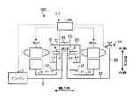
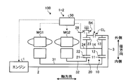
- FIG. 1 is a main part skeleton diagram of a vehicle according to an embodiment.
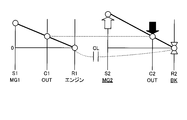
- FIG. 2 is a diagram illustrating an engagement table of the hybrid vehicle drive device according to the embodiment.
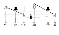
- FIG. 3 is a collinear diagram related to the EV-1 mode.
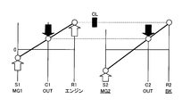
- FIG. 4 is a collinear diagram related to the EV-2 mode.
- FIG. 5 is a collinear diagram related to the HV-1 mode.
- FIG. 6 is a collinear diagram related to the HV-2 mode.
- FIG. 7 is a collinear diagram in the four-element mode.
- FIG. 8 is an explanatory diagram of the theoretical transmission efficiency of the hybrid vehicle drive device according to the embodiment.
- FIG. 9 is a main part skeleton diagram of a vehicle according to a first modification of the embodiment.
- FIG. 9 is a main part skeleton diagram of a vehicle according to a first modification of the embodiment.
- FIG. 10 is a main part skeleton diagram of a vehicle according to a second modification of the embodiment.
- FIG. 11 is a main part skeleton diagram of a vehicle according to a third modification of the embodiment.
- FIG. 12 is a main part skeleton diagram of the vehicle according to the fourth modification example of the embodiment.
- FIG. 1 is a main part skeleton diagram of a vehicle 100 according to an embodiment of the present invention
- FIG. 2 is a diagram showing an engagement table of a hybrid vehicle drive device 1-1 according to the embodiment.
- the hybrid vehicle drive device 1-1 is a hybrid system having two planetary gears, two motors, and a plurality of engagement devices.
- the electric torque converter mode and the four-element planetary are shared. It has a composite split mode coupled in the order of MG1-MG2-output-engine on the diagram.
- the hybrid vehicle drive device 1-1 has one brake and one clutch as an engagement device, and these engagement / non-engagement results in two or more modes during hybrid operation and the number of drive MGs during EV operation. Two different modes can be realized. Further, the hybrid vehicle drive device 1-1 has two mechanical points on the low gear side, so that high transmission efficiency can be desired.
- a vehicle 100 shown in FIG. 1 includes an engine 1, a first planetary gear mechanism 10, a second planetary gear mechanism 20, a first rotating electrical machine MG1, a second rotating electrical machine MG2, a clutch CL, a brake BK, and an ECU 50. Yes.
- the hybrid vehicle drive device 1-1 according to the present embodiment includes the first planetary gear mechanism 10, the second planetary gear mechanism 20, the clutch CL, and the brake BK.
- the hybrid vehicle drive device 1-1 may further include an ECU 50.
- the engine 1 which is an example of the engine converts the combustion energy of the fuel into a rotary motion of the rotary shaft and outputs it.
- the rotating shaft of the engine 1 is connected to the input shaft 2.
- the input shaft 2 is an input shaft of the first planetary gear mechanism 10 and is arranged coaxially with the rotation shaft of the engine 1.
- the torque of the engine 1 is input to the first planetary gear mechanism 10 via the input shaft 2.
- the first planetary gear mechanism 10 is an example of a first differential mechanism.
- the first planetary gear mechanism 10 is a single pinion type and includes a first sun gear 11, a first pinion gear 12, a first ring gear 13, and a first carrier 14.
- the first ring gear 13 is coaxial with the first sun gear 11 and is disposed on the radially outer side of the first sun gear 11.
- the first pinion gear 12 is disposed between the first sun gear 11 and the first ring gear 13 and meshes with the first sun gear 11 and the first ring gear 13, respectively.
- the first pinion gear 12 is rotatably supported by the first carrier 14.
- the rotating shaft 31 of the first rotating electrical machine MG1 is coaxial with the input shaft 2 and is disposed on the radially outer side of the input shaft 2.
- the first sun gear 11 is connected to the rotating shaft 31. That is, the first sun gear 11 is rotatably supported coaxially with the input shaft 2 and is connected to the first rotating electrical machine MG1.
- the first ring gear 13 is connected to the input shaft 2 and rotates integrally with the input shaft 2. That is, the first ring gear 13 is connected to the engine 1 and can rotate integrally with the engine 1.
- the first carrier 14 is connected to the second carrier 24 via the cylindrical member 27.
- the cylindrical member 27 has a cylindrical shape and is disposed on the radially outer side of the first planetary gear mechanism 10 and the second planetary gear mechanism 20.
- the second planetary gear mechanism 20 is an example of a second differential mechanism.
- the second planetary gear mechanism 20 is a single pinion type and includes a second sun gear 21, a second pinion gear 22, a second ring gear 23, and a second carrier 24.
- the second sun gear 21 corresponds to the first rotating element
- the second carrier 24 corresponds to the second rotating element
- the second ring gear 23 corresponds to the third rotating element.
- the second ring gear 23 is coaxial with the second sun gear 21 and is disposed on the radially outer side of the second sun gear 21.
- the second pinion gear 22 is disposed between the second sun gear 21 and the second ring gear 23 and meshes with the second sun gear 21 and the second ring gear 23, respectively.
- the second pinion gear 22 is rotatably supported by the second carrier 24.
- the rotary shaft 25 of the second ring gear 23 is coaxial with the input shaft 2 and is disposed on an extension line of the input shaft 2.
- the rotating shaft 25 is rotatably supported.
- the second sun gear 21 is connected to the rotating shaft 32 of the second rotating electrical machine MG2.
- the rotating shaft 32 of the second rotating electrical machine MG2 is disposed coaxially with the rotating shaft 25 of the second ring gear 23 and on the radially outer side of the rotating shaft 25.
- the first carrier 14, the second carrier 24, and the cylindrical member 27 are rotatably supported on the same axis as the input shaft 2.
- the first pinion gear 12 can rotate (revolve) around the central axis of the input shaft 2 together with the first carrier 14, and is supported by the first carrier 14 to rotate (rotate) around the central axis of the first pinion gear 12. It is possible.
- the second pinion gear 22 can rotate (revolve) around the central axis of the rotation shaft 25 together with the second carrier 24, and is supported by the second carrier 24 to rotate around the central axis of the second pinion gear 22 (rotation). It is possible.
- a counter drive gear 28 is disposed on the outer peripheral surface of the cylindrical member 27.
- the counter drive gear 28 is connected to drive wheels via a gear mechanism including a differential device and a speed reduction mechanism and a drive shaft.
- the counter drive gear 28 is an output gear disposed on the output shafts of the planetary gear mechanisms 10 and 20, and outputs torque output from the first planetary gear mechanism 10 and the second planetary gear mechanism 20 to the drive wheels.
- the first carrier 14 and the second carrier 24 are connected to drive wheels via a counter drive gear 28, a gear mechanism, and a drive shaft.
- the clutch CL is a clutch device that can connect the input shaft 2 and the rotary shaft 25.
- the second ring gear 23 is connected to the engine 1 and the first ring gear 13 via the clutch CL.
- the clutch CL can be, for example, a friction engagement type clutch, but is not limited thereto, and a known clutch device such as a meshing type clutch may be used as the clutch CL.
- a meshed dog clutch or the like is used as the clutch CL, drag loss in the opened state is suppressed.
- the clutch CL is driven or engaged or released by an actuator that is operated by, for example, hydraulic pressure or electromagnetic force. When an electromagnetic actuator is used, a hydraulic circuit is not necessary, and the transaxle can be simplified and reduced in weight.
- the fully engaged clutch CL can connect the input shaft 2 and the rotary shaft 25 and rotate the input shaft 2 and the rotary shaft 25 integrally. That is, the fully engaged clutch CL restricts relative rotation of the engine 1, the first ring gear 13, and the second ring gear 23.
- the opened clutch CL disconnects the input shaft 2 and the rotary shaft 25 and allows relative rotation between the input shaft 2 and the rotary shaft 25. That is, the opened clutch CL allows relative rotation of the engine 1, the first ring gear 13, and the second ring gear 23.
- the clutch CL can be controlled to be in a semi-engaged state.
- the brake BK is a brake device that can regulate the rotation of the second ring gear 23 by engaging it.
- the brake BK has an engagement element disposed on the disk member 26 and an engagement element connected to the vehicle body side, for example, a case that houses the rotating electrical machines MG1, MG2, the planetary gear mechanisms 10, 20, and the like.
- the disk member 26 is a disk-shaped member that protrudes radially outward from the rotation shaft 25 of the second ring gear 23.
- the brake BK may be a friction engagement type clutch device similar to the clutch CL, but is not limited thereto, and a known clutch device such as a dog clutch, for example, a dog clutch may be used as the brake BK. .
- the brake BK is driven or engaged or released by an actuator that is operated by, for example, hydraulic pressure or electromagnetic force.
- the fully engaged brake BK connects the second ring gear 23 and the vehicle body side and can regulate the rotation of the second ring gear 23.
- the released brake BK disconnects the second ring gear 23 from the vehicle body side and allows the second ring gear 23 to rotate. Note that the brake BK can be controlled to a half-engaged state.
- the first rotating electrical machine MG1, the first planetary gear mechanism 10, the counter drive gear 28 and the clutch CL, the second planetary gear mechanism 20, and the second rotation are arranged on the same axis as the rotation axis of the engine 1 in order from the side closer to the engine 1.
- An electric machine MG2 and a brake BK are arranged.
- the first rotating electrical machine MG1 and the second rotating electrical machine MG2 each have a function as a motor (electric motor) and a function as a generator.
- the first rotating electrical machine MG1 and the second rotating electrical machine MG2 are connected to a battery via an inverter.
- the first rotating electrical machine MG1 and the second rotating electrical machine MG2 can convert the electric power supplied from the battery into mechanical power and output it, and are driven by the input power to convert the mechanical power into electric power. Can be converted.
- the electric power generated by the rotating electrical machines MG1 and MG2 can be stored in the battery.
- an AC synchronous motor generator can be used as the first rotating electrical machine MG1 and the second rotating electrical machine MG2.
- the ECU 50 causes the first rotating electrical machine MG1 to function mainly as a rotating electrical machine that takes the reaction force of the engine 1, and causes the second rotating electrical machine MG2 to function mainly as a rotating electrical machine for driving.
- the present invention is not limited to this, and the first rotating electrical machine MG1 may be made to mainly function as a rotating electrical machine for driving and the second rotating electrical machine MG2 may be made to function mainly as a rotating electrical machine for receiving reaction force.
- the vehicle 100 includes an ECU 50.
- the ECU 50 is an electronic control unit having a computer.
- the ECU 50 has a function as a control device that controls each part of the vehicle 100.
- the ECU 50 is connected to the engine 1, the first rotating electrical machine MG1, the second rotating electrical machine MG2, the clutch CL, and the brake BK, and the engine 50, the first rotating electrical machine MG1, the second rotating electrical machine MG2, the clutch CL, and the brake BK. Can be controlled.
- the ECU 50 can control the torque and rotation speed of the engine 1 by fuel injection control, ignition control, electronic throttle control, and the like of the engine 1. Further, the ECU 50 can control the rotation speed and torque of the first rotating electrical machine MG1 and the second rotating electrical machine MG2. Further, the ECU 50 can control the engagement / release state of the clutch CL and the brake BK by controlling the hydraulic pressure supplied to the clutch CL and the brake BK from a hydraulic control device (not shown).
- the ECU 50 has a vehicle speed, an accelerator opening, a rotational speed of the first rotating electrical machine MG1 (hereinafter also simply referred to as “MG1 rotational speed”), and a rotational speed of the second rotating electrical machine MG2 (hereinafter simply referred to as “MG2 rotational speed”). And a sensor for detecting the output shaft speed, the state of the battery, and the like. ECU 50 calculates a required output for vehicle 100 based on information acquired from each sensor, and can control engine 1, rotating electrical machines MG1, MG2, clutch CL, brake BK, and the like.
- FIG. 2 is a view showing an operation engagement table of the hybrid vehicle drive device 1-1 according to the present embodiment.
- the ⁇ marks in the brake BK column and the clutch CL column indicate engagement, and the blank column indicates disengagement.
- the vehicle 100 can selectively execute hybrid (HV) traveling or EV traveling.
- the HV travel is a travel mode in which the vehicle 100 travels using the engine 1 as a power source.
- HV traveling in addition to the engine 1, at least one of the first rotating electrical machine MG1 and the second rotating electrical machine MG2 can be used as a power source.
- EV traveling is a traveling mode in which traveling is performed using at least one of the first rotating electrical machine MG1 and the second rotating electrical machine MG2 as a power source. In EV traveling, it is possible to travel with the engine 1 stopped.
- the hybrid vehicle drive device 1-1 according to the present embodiment has an EV-1 mode and an EV-2 mode as EV travel modes.
- the EV-1 mode is a single motor EV mode in which the vehicle 100 travels using the second rotating electrical machine MG2 as a single power source.
- the EV-2 mode is a dual motor EV mode in which the vehicle 100 can travel using the first rotating electrical machine MG1 and the second rotating electrical machine MG2 as power sources.
- FIG. 3 is a collinear diagram related to the EV-1 mode.
- symbols S1, C1, and R1 indicate the first sun gear 11, the first carrier 14, and the first ring gear 13, respectively.
- Reference numerals S2, C2, and R2 denote the second sun gear 21, the second carrier 24, and the second ring gear 23, respectively.
- the ECU 50 engages the brake BK and releases the clutch CL.
- the rotation of the second ring gear 23 is restricted. Further, since the clutch CL is in the released state, the engine 1, the first ring gear 13, and the second ring gear 23 can be rotated relative to each other.
- the first carrier 14 that is the output element of the first planetary gear mechanism 10 and the second carrier 24 that is the output element of the second planetary gear mechanism 20 are connected to each other and rotate at the same rotational speed.
- the ECU 50 causes the vehicle 100 to travel using the second rotating electrical machine MG2 as a power source.
- the second ring gear 23 whose rotation is restricted functions as a reaction force receiver for the torque of the second rotating electrical machine MG2 (hereinafter also simply referred to as “MG2 torque”), and outputs the MG2 torque from the second carrier 24.
- MG2 torque the torque of the second rotating electrical machine MG2
- the second planetary gear mechanism 20 decelerates the rotation of the second rotating electrical machine MG2 and outputs it from the second carrier 24. That is, the second planetary gear mechanism 20 can amplify and output the MG2 torque.
- the brake BK regulates the rotation of the second ring gear 23
- the reduction ratio at which the second planetary gear mechanism 20 decelerates the rotation of the second rotating electrical machine MG2 is relatively large.
- the degree of deceleration when the second sun gear 21 is fixed is The smallest degree of deceleration when the second ring gear 23 is fixed is the largest. Therefore, in the hybrid vehicle driving device 1-1 according to the present embodiment, the amplification factor of the MG2 torque can be increased, and the shortage of the starting driving force during EV traveling can be suppressed.
- an increase in the size of the second rotating electrical machine MG2 for securing the starting driving force is suppressed.
- the second rotating electrical machine MG2 can be operated at a thermally advantageous operating point.
- the second rotating electrical machine MG2 can output a positive torque from the second carrier 24 by generating a positive torque by outputting a positive torque, thereby generating a driving force in the forward direction in the vehicle 100. Further, the second rotating electrical machine MG2 can output negative torque from the second carrier 24 by outputting negative torque and rotating negatively, and can cause the vehicle 100 to generate a backward driving force.
- the positive rotation is the rotation direction of the first carrier 14 and the second carrier 24 when the vehicle 100 moves forward, and the positive torque indicates the torque in the positive rotation direction.
- the first ring gear 13 connected to the engine 1 stops rotating, and the first sun gear 11 idles.
- regenerative power generation can be performed by the second rotating electrical machine MG2 to generate a braking force.
- FIG. 4 is a collinear diagram related to the EV-2 mode.
- the ECU 50 engages the brake BK and the clutch CL in the EV-2 mode.
- the clutch CL When the clutch CL is in the engaged state, the relative rotation of the engine 1, the first ring gear 13, and the second ring gear 23 is restricted. Further, when the brake BK is in the engaged state, the rotation of the second ring gear 23 is restricted. Accordingly, in the EV-2 mode, the rotation of the engine 1, the first ring gear 13 and the second ring gear 23 is restricted.
- the first ring gear 13 whose rotation is restricted functions as a reaction force receiver for the torque of the first rotating electrical machine MG1 (hereinafter also simply referred to as “MG1 torque”), and outputs the MG1 torque from the first carrier 14.
- the first rotating electrical machine MG1 can output a positive torque from the first carrier 14 by generating a positive torque by outputting a positive torque, thereby causing the vehicle 100 to generate a driving force in the forward direction. Further, the first rotating electrical machine MG1 can output negative torque from the first carrier 14 by outputting negative torque and rotating negatively, and can cause the vehicle 100 to generate a driving force in the reverse direction.
- the second ring gear 23 whose rotation is restricted functions as a reaction force receiver for the MG2 torque, and can output the MG2 torque from the second carrier 24.
- the second rotating electrical machine MG2 can output positive torque from the second carrier 24 by generating positive torque by outputting positive torque, and can generate a driving force in the forward direction in the vehicle 100. Further, the second rotating electrical machine MG2 can output negative torque from the second carrier 24 by outputting negative torque and rotating negatively, and can cause the vehicle 100 to generate a backward driving force.
- the vehicle 100 can travel by generating a travel driving force by at least one of the first rotating electrical machine MG1 and the second rotating electrical machine MG2.
- the first rotating electrical machine MG1 and the second rotating electrical machine MG2 are used as power sources, and the MG1 torque and MG2 torque are output from the counter drive gear 28 to the driving wheels, respectively, to drive the vehicle 100.
- the MG1 torque and MG2 torque are output from the counter drive gear 28 to the driving wheels, respectively, to drive the vehicle 100.
- at least one of the first rotating electrical machine MG1 and the second rotating electrical machine MG2 can be idled or regenerated.
- FIG. 5 is a collinear diagram related to the HV-1 mode.
- the ECU 50 engages the brake BK and releases the clutch CL. Since the brake BK is in the engaged state, the second ring gear 23 functions as a reaction force receiver for the MG2 torque and can output the MG2 torque from the second carrier 24.
- the ECU 50 can cause the first rotating electrical machine MG1 to output torque so that the first rotating electrical machine MG1 functions as a reaction force receiver for the torque of the engine 1 (hereinafter also simply referred to as “engine torque”).
- engine torque The first rotating electrical machine MG1 can output the positive torque output from the engine 1 from the first carrier 14 by outputting the positive torque.
- the first rotating electrical machine MG1 When the first rotating electrical machine MG1 outputs a positive torque and receives a reaction force in a negative rotation state, the first rotating electrical machine MG1 can generate a power and recover a part of the power of the engine 1 as electric power.
- the second rotating electrical machine MG2 can output an assist torque that assists the engine 1 by outputting a positive torque, or can perform regenerative power generation during deceleration.
- the rotation of the engine 1 can be decelerated and output from the first carrier 14 and the degree of deceleration can be controlled by controlling the first rotating electrical machine MG1. That is, the HV-1 mode is an electric torque converter mode capable of amplifying the engine torque by electrical control and outputting it from the first carrier 14 and controlling the amplification degree.
- FIG. 6 is a collinear diagram related to the HV-2 mode.
- the ECU 50 releases the brake BK and engages the clutch CL.
- the brake BK is in the released state
- the second ring gear 23 is allowed to rotate.
- the clutch CL is in the engaged state, the relative rotation between the first ring gear 13 and the second ring gear 23 is restricted, and both can rotate integrally.
- the first rotating electrical machine MG1 can output the engine torque from the first carrier 14 by receiving a reaction force of the engine torque by outputting a positive torque.
- the second rotating electrical machine MG ⁇ b> 2 receives the reaction force of the engine torque by outputting a positive torque, and can output the engine torque from the second carrier 24.
- the reaction force can be applied to the power output from the engine 1 by either the first rotating electrical machine MG1 or the second rotating electrical machine MG2.
- the reaction force of the engine 1 can be received by one or both of the first rotating electrical machine MG1 and the second rotating electrical machine MG2, and can be operated at an efficient operating point, or a restriction such as torque limitation due to heat. Can be relaxed. Therefore, high efficiency of the hybrid vehicle 100 can be achieved.
- the power of the engine 1 is divided into the output shaft and the first rotating electrical machine MG1 using the first planetary gear mechanism 10 as a power split planetary, or the output shaft using the second planetary gear mechanism 20 as a power split planetary. This is a composite split mode in which the power of the engine 1 can also be divided into the second rotating electrical machine MG2.
- the reaction force is preferentially received by the rotary electric machine that can operate efficiently among the first rotary electric machine MG1 and the second rotary electric machine MG2, the efficiency can be improved.
- the necessary reaction force can be satisfied by assisting with regeneration (or output) of the other rotating electrical machine.
- FIG. 7 is a collinear diagram for the 4-element mode, and is a collinear diagram for the EV-2 mode.
- the first ring gear 13 and the second ring gear 23 are coupled to form one rotating element.
- the first planetary gear mechanism 10 and the second planetary gear mechanism 20 include the first sun gear 11, the first carrier 14 and the second carrier 24, the first ring gear 13 and the second ring gear 23, and the second sun gear 21.
- the four rotating elements function as a four-element differential mechanism that rotates while being associated with each other.
- first sun gear 11 first rotating electrical machine MG1
- second sun gear 21 second Rotating electrical machine MG2
- first carrier 14 and second carrier 24 output
- first ring gear 13 engine 1
- second ring gear 23 second ring gear 23
- the first planetary gear mechanism 10 and the second planetary gear mechanism 20 may be configured so that the ring gears 23 are arranged in order.
- the second sun gear is larger than the distance between the axis (S1 axis) indicating the rotation speed of the first sun gear 11 and the axis (C1 axis) indicating the rotation speed of the first carrier 14 in the alignment chart of FIG.
- gear ratios of the planetary gear mechanisms 10 and 20 are determined so that the distance between the axis indicating the rotational speed of 21 (S2 axis) and the axis indicating the rotational speed of the second carrier 24 (C2 axis) is increased. Good.
- the first planetary gear mechanism 10 and the second planetary gear mechanism 20 are each a single pinion type. Accordingly, in the nomographic chart in the four-element mode, the position of the axis indicating the rotation speed of the first sun gear 11 (S1 axis) and the axis indicating the rotation speed of the second sun gear 21 (S2 axis) do not overlap. . This is because, in the collinear diagram of the single pinion type planetary gear mechanism, the position of the shaft indicating the rotation speed of the carrier is more than the center point between the axis indicating the rotation speed of the sun gear and the axis indicating the rotation speed of the ring gear. This is because it is located on the shaft side indicating the rotation speed of the gear.
- At least one of the first planetary gear mechanism 10 and the second planetary gear mechanism 20 is of a double pinion type or the like, so that the S1 axis indicating the rotation speed of the first sun gear 11 and the second sun gear 21 (third It is also possible to overlap the S2 axis indicating the rotation speed of the rotation element).
- the hybrid vehicle drive device 1-1 has two mechanical points in the HV-2 mode, thereby realizing a highly efficient hybrid system. be able to.
- the mechanical point is a mechanical transmission point and a high-efficiency operating point with zero electrical path.
- FIG. 8 is an explanatory diagram of the theoretical transmission efficiency of the hybrid vehicle drive device 1-1 according to this embodiment.
- the horizontal axis represents the transmission ratio
- the vertical axis represents the theoretical transmission efficiency.
- the transmission ratio is a ratio (reduction ratio) of the input side rotational speed to the output side rotational speed of the first planetary gear mechanism 10 and the second planetary gear mechanism 20, for example, the first carrier 14 and the second carrier 24.
- the ratio of the rotation speed of the first ring gear 13 to the rotation speed of On the horizontal axis the left side is the high gear side with a small gear ratio, and the right side is the low gear side with a large gear ratio.
- the theoretical transmission efficiency is 1 when the power input to the planetary gear mechanisms 10 and 20 is all transmitted to the counter drive gear 28 by mechanical transmission without passing through the electric path.
- the broken line 61 is a transmission efficiency line in the HV-1 mode
- the solid line 62 is a transmission efficiency line in the HV-2 mode.
- the transmission efficiency line 61 in the HV-1 mode has the maximum efficiency at the speed ratio ⁇ 1.
- the gear ratio ⁇ 1 is a gear ratio at which the rotation speed of the first rotating electrical machine MG1 (first sun gear 11) is zero. Therefore, at the speed ratio ⁇ 1, an electric path due to the reaction force of the first rotating electrical machine MG1 does not occur, and power can be transmitted from the engine 1 to the counter drive gear 28 only by mechanical power transmission.
- the speed ratio ⁇ 1 is also referred to as “first mechanical transmission speed ratio ⁇ 1”.
- the first machine transmission speed ratio ⁇ 1 is a speed ratio on the underdrive side, that is, a speed ratio larger than the constant speed.
- the transmission efficiency line 62 in the HV-2 mode indicates the transmission efficiency when a reaction force of the engine torque is appropriately received by at least one of the first rotating electrical machine MG1 and the second rotating electrical machine MG2.
- the torque may be shared between the first rotating electrical machine MG1 and the second rotating electrical machine MG2 so that power can be transmitted most efficiently with respect to the gear ratio.
- the transmission efficiency line 62 in the HV-2 mode has a mechanical point at the speed ratio ⁇ 2 in addition to the first mechanical transmission speed ratio ⁇ 1.
- the gear ratio ⁇ 2 is a gear ratio at which the rotation speed of the second rotating electrical machine MG2 (second ring gear 23) is zero. Therefore, at the speed ratio ⁇ 2, an electric path due to the reaction force of the second rotating electrical machine MG2 does not occur, and power can be transmitted from the engine 1 to the counter drive gear 28 only by mechanical power.
- the speed ratio ⁇ 2 is also referred to as “second mechanical transmission speed ratio ⁇ 2”.
- the second machine transmission speed ratio ⁇ 2 is a speed ratio on the low gear side with respect to the first machine transmission speed ratio ⁇ 1.
- the S2 axis indicating the rotation speed of the second sun gear 21 is C1 indicating the rotation speed of the carriers 14 and 24 relative to the S1 axis indicating the rotation speed of the first sun gear 11.
- the relative relationship between the first mechanical transmission speed ratio ⁇ 1 and the second mechanical transmission speed ratio ⁇ 2 is determined according to the gear ratio ⁇ 1 of the first planetary gear mechanism 10 and the gear ratio ⁇ 2 of the second planetary gear mechanism 20.
- the gear ratios ⁇ 1 and ⁇ 2 can be expressed by the following formulas (1) and (2), for example.
- ⁇ 1 number of teeth of first sun gear 11 / number of teeth of first ring gear 13
- ⁇ 2 number of teeth of second sun gear 21 / number of teeth of second ring gear 23 (2)
- the first machine transmission speed ratio ⁇ 1 and the second machine transmission speed ratio ⁇ 2 become closer to each other.
- the first machine transmission speed ratio ⁇ 1 and the second machine transmission speed ratio ⁇ 2 are separated from each other on the alignment chart shown in FIG. 7, the first machine transmission speed ratio ⁇ 1 and the second machine The difference from the transmission speed ratio ⁇ 2 increases.
- the hybrid vehicle drive device 1-1 includes the two HV modes including the HV-2 mode having two mechanical points in the low gear range, and the two rotating electric machines MG1 and MG2.
- Two EV modes including the EV-2 mode for driving can be realized.
- the two HV modes and the two EV modes can be realized with a simple configuration of the two planetary gear mechanisms 10, 20, one clutch CL, and one brake BK.
- the hybrid vehicle drive device 1-1 has two mechanical points on the low gear side with respect to the constant speed (gear ratio 1) in the HV-2 mode, and thus has a high transmission efficiency during low gear operation. Can be realized. Further, the interval between the first machine transmission speed ratio ⁇ 1 and the second machine transmission speed ratio ⁇ 2 tends to be relatively narrow. For example, in the second planetary gear mechanism 20, the first sun gear 21 is the first rotating element, the second carrier 24 is the second rotating element, and the second ring gear 23 is the third rotating element. The interval between the mechanical transmission speed ratio ⁇ 1 and the second mechanical transmission speed ratio ⁇ 2 is reduced. In other words, although the range of the gear ratio for achieving high efficiency is narrow, the gear train can output the driving force with low loss within the range.
- the reaction force of the engine 1 can be received by sharing the torque with one or both of the rotating electrical machines MG1 and MG2. Therefore, it becomes possible to operate the rotating electrical machines MG1 and MG2 at an efficient operating point, and to ease restrictions such as torque limitation due to heat.
- the hybrid vehicle drive device 1-1 has an EV-2 mode that can be driven by two rotating electric machines MG1 and MG2 as an EV travel mode. Therefore, it is possible to generate (or regenerate) the torque by sharing one or both of the rotating electrical machines MG1 and MG2. As a result, it becomes possible to operate the rotating electrical machines MG1 and MG2 at an efficient operating point, and to ease restrictions such as torque limitation due to heat.
- the first planetary gear mechanism 10 and the second planetary gear mechanism 20 are single pinion type planetary gear mechanisms, and therefore, the number of meshing of the gears is small, which is advantageous in terms of loss reduction. . Further, since the output shaft can be arranged at the outermost diameter, there is an advantage that it is easy to adapt to the multi-axis FF structure.
- the planetary gear mechanisms 10 and 20 have the highest rotational speed at the sun gears 11 and 21, it is advantageous in terms of strength such as centrifugal force.
- FIG. 9 is a main part skeleton diagram of a vehicle according to a first modification of the embodiment.
- the hybrid vehicle drive device 1-2 according to the present modification differs from the hybrid vehicle drive device 1-1 of the above embodiment in that electrical parts and mechanical parts are arranged together. .
- the first rotating electrical machine MG1, the second rotating electrical machine MG2, the counter drive gear 28, the second planetary gear mechanism 20 and the brake BK are sequentially arranged from the side closer to the engine 1.
- a clutch CL and a first planetary gear mechanism 10 are disposed.
- a disk member 3 is connected to the end of the input shaft 2 opposite to the engine side.
- the input shaft 2 is connected to the first ring gear 13 via the disk member 3.
- the rotating shaft 31 of the first rotating electrical machine MG1 is hollow and is disposed on the radially outer side of the input shaft 2.
- the rotating shaft 32 of the second rotating electrical machine MG2 is hollow and is disposed on the radially outer side of the rotating shaft 31 of the first rotating electrical machine MG1.
- the brake BK is disposed on the outer side in the radial direction of the second ring gear 23.
- the brake BK regulates the engagement of the rotation of the second ring gear 23.
- the clutch CL connects and disconnects the engine 1, the first ring gear 13, and the second ring gear 23.
- electrical system parts such as the rotating electrical machines MG1 and MG2 and mechanical system parts such as the planetary gear mechanisms 10 and 20, the clutch CL, and the brake BK are arranged together. be able to.
- electrical parts and mechanical parts can be assembled in different cases in different factories. Therefore, the space and weight of parts to be transported can be reduced.
- inspection and initial setting after each assembly can be performed separately at the component stage.
- FIG. 10 is a main part skeleton diagram of a vehicle according to a second modification of the embodiment.
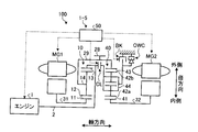
- the hybrid vehicle drive device 1-3 according to this modification is different from the hybrid vehicle drive device 1-1 of the above embodiment in that a one-way clutch OWC is provided.
- the one-way clutch OWC makes it unnecessary to engage the brake BK when starting the EV mode.
- the one-way clutch OWC is arranged in parallel with the brake BK.
- the one-way clutch OWC regulates the rotation of the second ring gear 23.
- the one-way clutch OWC allows the second ring gear 23 to rotate in the positive direction and restricts the rotation in the negative direction.
- the one-way clutch OWC can be a sprag type, for example.
- the inner ring of the one-way clutch OWC is connected to the disc member 26, and the outer ring is connected to the vehicle body side. When the inner ring tries to rotate relative to the outer ring in the negative direction, the sprags mesh with each other to restrict the relative rotation between the inner ring and the outer ring.
- the one-way clutch OWC can function as a reaction force receiver for the MG2 torque in the EV-1 mode.
- a negative torque acts on the second ring gear 23 and the one-way clutch OWC is engaged.
- the one-way clutch OWC functions as a reaction force receiver for the MG2 torque, and can output the MG2 torque from the second carrier 24.
- the hybrid vehicle drive apparatus 1-3 According to the hybrid vehicle drive apparatus 1-3 according to this modification, it is not necessary to engage the brake BK when starting the EV-1 mode. Therefore, the oil pump operation in a stopped state or the like becomes unnecessary, and the control becomes simple and the energy required for driving the electric oil pump is reduced.
- FIG. 11 is a main part skeleton diagram of a vehicle according to a third modification of the embodiment.
- the hybrid vehicle drive apparatus 1-4 according to this modification is different from the hybrid vehicle drive apparatus 1-2 according to the first modification in that a one-way clutch OWC is provided.
- the one-way clutch OWC is arranged in parallel with the brake BK.
- the one-way clutch OWC regulates the rotation of the second ring gear 23.
- the one-way clutch OWC allows the second ring gear 23 to rotate in the positive direction and restricts the rotation in the negative direction.
- the one-way clutch OWC can be a sprag type, for example.
- the inner ring of the one-way clutch OWC is connected to the second ring gear 23, and the outer ring is connected to the vehicle body side. When the inner ring tries to rotate relative to the outer ring in the negative direction, the sprags mesh with each other to restrict the relative rotation between the inner ring and the outer ring.
- the one-way clutch OWC according to the present modification can achieve the same effects as the one-way clutch OWC according to the second modification.
- FIG. 12 is a main part skeleton diagram of the vehicle according to the fourth modification example of the embodiment.
- the hybrid vehicle drive device 1-5 according to this modification differs from the hybrid vehicle drive device 1-3 according to the second modification of the above embodiment in that the second planetary gear mechanism 40 is a double pinion type. It is a point.
- the first planetary gear mechanism 10 may be a double pinion type.
- the second planetary gear mechanism 40 includes a second sun gear 41, an inner second pinion gear 42a, an outer second pinion gear 42b, a second ring gear 43, and a second carrier 44.
- the second ring gear 43 is connected to the first carrier 14 via the cylindrical member 29.
- a counter drive gear 28 is disposed on the outer peripheral surface of the cylindrical member 29.
- the brake BK can regulate the rotation of the second carrier 44.
- the one-way clutch OWC allows positive rotation of the second carrier 44 and restricts negative rotation.
- the inner second pinion gear 42a meshes with the second sun gear 41 and the outer second pinion gear 42b, respectively.
- the outer second pinion gear 42b meshes with the inner second pinion gear 42a and the second ring gear 43, respectively.
- the inner second pinion gear 42 a and the outer second pinion gear 42 b are rotatably supported by the second carrier 44.
- the second carrier 44 is connected to the engine 1 and the first ring gear 13 via the clutch CL.
- the inner second pinion gear 42a and the outer second pinion gear 42b can rotate (revolve) around the central axis of the rotary shaft 32 together with the second carrier 44, and are supported by the second carrier 44 around the respective central axes. Can be rotated (rotated).
- the second sun gear 41 is connected to the rotary shaft 32 of the second rotary electric machine MG2. That is, in the second planetary gear mechanism 40 according to this modification, the second sun gear 41 corresponds to the first rotation element, the second ring gear 43 corresponds to the second rotation element, and the second carrier 44 rotates the third time. Corresponds to the element.
- the collinear diagram in the four-element mode of the hybrid vehicle drive device 1-5 according to this modification, the collinear diagram in the four-element mode of the hybrid vehicle drive device 1-1 according to the embodiment (see FIG. 7). ) And partly different. Specifically, the axis indicating the rotation speed of the second carrier 44 is the rightmost axis, and the axis indicating the rotation speed of the second ring gear 43 is the second axis from the right. That is, the arrangement order of the rotating elements of the first planetary gear mechanism 10 and the second planetary gear mechanism 40 when the clutch CL is engaged is the first sun gear 11, the second sun gear 41, the first The carrier 14, the second ring gear 43, the first ring gear 13, and the second carrier 44 are in this order.
- the position of the shaft indicating the rotational speed of the first sun gear and the rotational speed of the second sun gear 41 There is a case where the position of the axis indicating is switched. That is, the arrangement order of the rotating elements of the first planetary gear mechanism 10 and the second planetary gear mechanism 40 when the clutch CL is engaged is the second sun gear 41, the first sun gear 11, the first The order of the carrier 14, the second ring gear 43, the first ring gear 13, and the second carrier 44 may be used.
- Hybrid vehicle drive system 1 Engine 10 First planetary gear mechanism 11 First sun gear 13 First ring gear 14 First carrier 20, 40 Second Planetary gear mechanism 21, 41 Second sun gear 23, 43 Second ring gear 24, 44 Second carrier 50 ECU 100 vehicle BK brake CL clutch OWC one-way clutch MG1 first rotating electric machine MG2 second rotating electric machine
Landscapes
- Engineering & Computer Science (AREA)
- Chemical & Material Sciences (AREA)
- Combustion & Propulsion (AREA)
- Transportation (AREA)
- Mechanical Engineering (AREA)
- Electric Propulsion And Braking For Vehicles (AREA)
- Hybrid Electric Vehicles (AREA)
Abstract
This drive device comprises a first planetary gear mechanism (10), a second planetary gear mechanism (20), a clutch (CL), and a brake (BK), wherein: a first sun gear (11), which is the sun gear of the first planetary gear mechanism, is connected to a first rotary electric device (MG1); a first ring gear (13), which is the ring gear of the first planetary gear mechanism, is connected to an engine (1); a first carrier (14), which is the carrier of the first planetary gear mechanism, is connected to a second rotary element (24) of the second planetary gear mechanism and to a drive wheel; a first rotary element (21) of the second planetary gear mechanism is connected to a second rotary electric device (MG2); a third rotary element (23) of the second planetary gear mechanism is connected to the engine and the first ring gear via the clutch; the first rotary element is the sun gear of the second planetary gear mechanism; and the brake regulates the rotation of the third rotary element.
Description
本発明は、ハイブリッド車両用駆動装置に関する。
The present invention relates to a hybrid vehicle drive device.
従来、複数の走行モードを有するハイブリッド車両用駆動装置が提案されている。例えば、特許文献1には、共線図上における原動機と第1のモータ・ジェネレータと第2のモータ・ジェネレータと出力要素と反力要素との位置関係を変更するモード切換機構が設けられているハイブリッド駆動装置の技術が開示されている。
Conventionally, hybrid vehicle drive devices having a plurality of travel modes have been proposed. For example, Patent Document 1 is provided with a mode switching mechanism that changes the positional relationship among a prime mover, a first motor / generator, a second motor / generator, an output element, and a reaction force element on the nomograph. A hybrid drive technology is disclosed.
複数の走行モードを有するハイブリッド車両用駆動装置の構成を簡素にできることが望まれている。例えば、簡素な構成のハイブリッド車両用駆動装置によって、複数のEV走行モードと、複数のHV走行モードとを実現できることが望ましい。
It is desired that the configuration of a hybrid vehicle drive device having a plurality of travel modes can be simplified. For example, it is desirable that a plurality of EV driving modes and a plurality of HV driving modes can be realized by a hybrid vehicle drive device having a simple configuration.
本発明の目的は、簡素な構成で複数の走行モードを実現できるハイブリッド車両用駆動装置を提供することである。
An object of the present invention is to provide a hybrid vehicle drive device capable of realizing a plurality of travel modes with a simple configuration.
本発明のハイブリッド車両用駆動装置は、第一遊星歯車機構と、第二遊星歯車機構と、クラッチと、ブレーキとを備え、前記第一遊星歯車機構のサンギアである第一サンギアは第一回転電機に、前記第一遊星歯車機構のリングギアである第一リングギアはエンジンに、前記第一遊星歯車機構のキャリアである第一キャリアは前記第二遊星歯車機構の第二回転要素および駆動輪にそれぞれ接続され、前記第二遊星歯車機構の第一回転要素は第二回転電機に、第三回転要素は前記クラッチを介して前記エンジンおよび前記第一リングギアにそれぞれ接続されており、前記第一回転要素は、前記第二遊星歯車機構のサンギアであり、前記ブレーキは、前記第三回転要素の回転を規制することを特徴とする。
A drive device for a hybrid vehicle of the present invention includes a first planetary gear mechanism, a second planetary gear mechanism, a clutch, and a brake, and the first sun gear that is a sun gear of the first planetary gear mechanism is a first rotating electrical machine. In addition, the first ring gear, which is the ring gear of the first planetary gear mechanism, is the engine, and the first carrier, which is the carrier of the first planetary gear mechanism, is the second rotating element and the drive wheel of the second planetary gear mechanism. The first rotating element of the second planetary gear mechanism is connected to the second rotating electrical machine, and the third rotating element is connected to the engine and the first ring gear via the clutch. The rotating element is a sun gear of the second planetary gear mechanism, and the brake regulates the rotation of the third rotating element.
上記ハイブリッド車両用駆動装置において、前記クラッチが係合しているときの前記第一遊星歯車機構および前記第二遊星歯車機構の各回転要素の共線図における並び順は、前記第一サンギア、前記第一回転要素、前記第一キャリアおよび前記第二回転要素、前記第一リングギアおよび前記第三回転要素の順、あるいは、前記第一回転要素、前記第一サンギア、前記第一キャリアおよび前記第二回転要素、前記第一リングギアおよび前記第三回転要素の順であることが好ましい。
In the hybrid vehicle drive device, the arrangement order of the rotation elements of the first planetary gear mechanism and the second planetary gear mechanism when the clutch is engaged is the first sun gear, The first rotating element, the first carrier and the second rotating element, the first ring gear and the third rotating element in this order, or the first rotating element, the first sun gear, the first carrier and the first It is preferable that the order is the two-rotating element, the first ring gear, and the third rotating element.
上記ハイブリッド車両用駆動装置において、前記クラッチおよび前記ブレーキは、噛合い式の係合装置であることが好ましい。
In the hybrid vehicle drive device, the clutch and the brake are preferably meshing engagement devices.
上記ハイブリッド車両用駆動装置において、更に、前記第三回転要素の回転を規制するワンウェイクラッチを備えることが好ましい。
It is preferable that the hybrid vehicle drive device further includes a one-way clutch that restricts the rotation of the third rotation element.
上記ハイブリッド車両用駆動装置において、前記第二遊星歯車機構は、シングルピニオン式であり、前記第二回転要素は前記第二遊星歯車機構のキャリア、前記第三回転要素は前記第二遊星歯車機構のリングギアであることが好ましい。
In the hybrid vehicle drive device, the second planetary gear mechanism is a single pinion type, the second rotating element is a carrier of the second planetary gear mechanism, and the third rotating element is of the second planetary gear mechanism. A ring gear is preferred.
上記ハイブリッド車両用駆動装置において、前記第二遊星歯車機構は、ダブルピニオン式であり、前記第二回転要素は前記第二遊星歯車機構のリングギア、前記第三回転要素は前記第二遊星歯車機構のキャリアであることが好ましい。
In the hybrid vehicle drive device, the second planetary gear mechanism is a double pinion type, the second rotating element is a ring gear of the second planetary gear mechanism, and the third rotating element is the second planetary gear mechanism. It is preferable that the carrier.
本発明に係るハイブリッド車両用駆動装置は、第一遊星歯車機構と、第二遊星歯車機構と、クラッチと、ブレーキとを備える。第一遊星歯車機構のサンギアである第一サンギアは第一回転電機に、第一遊星歯車機構のリングギアである第一リングギアはエンジンに、第一遊星歯車機構のキャリアである第一キャリアは第二遊星歯車機構の第二回転要素および駆動輪にそれぞれ接続されている。第二遊星歯車機構の第一回転要素は第二回転電機に、第三回転要素はクラッチを介してエンジンおよび第一リングギアにそれぞれ接続されている。第一回転要素は、第二遊星歯車機構のサンギアである。ブレーキは、第三回転要素の回転を規制する。本発明に係るハイブリッド車両用駆動装置によれば、簡素な構成で複数の走行モードを実現できるという効果を奏する。
The hybrid vehicle drive device according to the present invention includes a first planetary gear mechanism, a second planetary gear mechanism, a clutch, and a brake. The first sun gear that is the sun gear of the first planetary gear mechanism is in the first rotating electrical machine, the first ring gear that is the ring gear of the first planetary gear mechanism is in the engine, and the first carrier that is the carrier of the first planetary gear mechanism is The second planetary gear mechanism is connected to the second rotating element and the drive wheel, respectively. The first rotating element of the second planetary gear mechanism is connected to the second rotating electric machine, and the third rotating element is connected to the engine and the first ring gear via a clutch. The first rotating element is a sun gear of the second planetary gear mechanism. The brake regulates the rotation of the third rotating element. According to the hybrid vehicle drive device of the present invention, there is an effect that a plurality of travel modes can be realized with a simple configuration.
以下に、本発明の実施形態に係るハイブリッド車両用駆動装置につき図面を参照しつつ詳細に説明する。なお、この実施形態によりこの発明が限定されるものではない。また、下記の実施形態における構成要素には、当業者が容易に想定できるものあるいは実質的に同一のものが含まれる。
Hereinafter, a hybrid vehicle drive device according to an embodiment of the present invention will be described in detail with reference to the drawings. In addition, this invention is not limited by this embodiment. In addition, constituent elements in the following embodiments include those that can be easily assumed by those skilled in the art or those that are substantially the same.
[実施形態]
図1から図8を参照して、実施形態について説明する。本実施形態は、ハイブリッド車両用駆動装置に関する。図1は、本発明の実施形態に係る車両100の要部スケルトン図、図2は、実施形態に係るハイブリッド車両用駆動装置1-1の係合表を示す図である。 [Embodiment]
The embodiment will be described with reference to FIGS. 1 to 8. The present embodiment relates to a hybrid vehicle drive device. FIG. 1 is a main part skeleton diagram of avehicle 100 according to an embodiment of the present invention, and FIG. 2 is a diagram showing an engagement table of a hybrid vehicle drive device 1-1 according to the embodiment.
図1から図8を参照して、実施形態について説明する。本実施形態は、ハイブリッド車両用駆動装置に関する。図1は、本発明の実施形態に係る車両100の要部スケルトン図、図2は、実施形態に係るハイブリッド車両用駆動装置1-1の係合表を示す図である。 [Embodiment]
The embodiment will be described with reference to FIGS. 1 to 8. The present embodiment relates to a hybrid vehicle drive device. FIG. 1 is a main part skeleton diagram of a
本実施形態に係るハイブリッド車両用駆動装置1-1は、2つのプラネタリギアと、2つのモータと、複数の係合装置とを有するハイブリッドシステムであって、電気トルコンモードと、4要素プラネタリが共線図上でMG1-MG2-出力-エンジンの順に結合された複合スプリットモードとを有する。ハイブリッド車両用駆動装置1-1は、係合装置として1つのブレーキと1つのクラッチを有し、これらの係合/非係合によりハイブリッド時の2以上のモードと、EV時の駆動MG数が異なる2つのモードを実現可能である。また、ハイブリッド車両用駆動装置1-1は、ローギア側に2つのメカニカルポイントを有することで、高い伝達効率を望むことができる。
The hybrid vehicle drive device 1-1 according to the present embodiment is a hybrid system having two planetary gears, two motors, and a plurality of engagement devices. The electric torque converter mode and the four-element planetary are shared. It has a composite split mode coupled in the order of MG1-MG2-output-engine on the diagram. The hybrid vehicle drive device 1-1 has one brake and one clutch as an engagement device, and these engagement / non-engagement results in two or more modes during hybrid operation and the number of drive MGs during EV operation. Two different modes can be realized. Further, the hybrid vehicle drive device 1-1 has two mechanical points on the low gear side, so that high transmission efficiency can be desired.
図1に示す車両100は、エンジン1、第一遊星歯車機構10、第二遊星歯車機構20、第一回転電機MG1、第二回転電機MG2、クラッチCL、ブレーキBKおよびECU50を含んで構成されている。また、本実施形態に係るハイブリッド車両用駆動装置1-1は、第一遊星歯車機構10、第二遊星歯車機構20、クラッチCLおよびブレーキBKを含んで構成されている。ハイブリッド車両用駆動装置1-1は、更に、ECU50を含んで構成されてもよい。
A vehicle 100 shown in FIG. 1 includes an engine 1, a first planetary gear mechanism 10, a second planetary gear mechanism 20, a first rotating electrical machine MG1, a second rotating electrical machine MG2, a clutch CL, a brake BK, and an ECU 50. Yes. The hybrid vehicle drive device 1-1 according to the present embodiment includes the first planetary gear mechanism 10, the second planetary gear mechanism 20, the clutch CL, and the brake BK. The hybrid vehicle drive device 1-1 may further include an ECU 50.
機関の一例であるエンジン1は、燃料の燃焼エネルギーを回転軸の回転運動に変換して出力する。エンジン1の回転軸は、入力軸2と接続されている。入力軸2は、第一遊星歯車機構10の入力軸であり、エンジン1の回転軸と同軸上に配置されている。エンジン1のトルクは、入力軸2を介して第一遊星歯車機構10に入力される。
The engine 1 which is an example of the engine converts the combustion energy of the fuel into a rotary motion of the rotary shaft and outputs it. The rotating shaft of the engine 1 is connected to the input shaft 2. The input shaft 2 is an input shaft of the first planetary gear mechanism 10 and is arranged coaxially with the rotation shaft of the engine 1. The torque of the engine 1 is input to the first planetary gear mechanism 10 via the input shaft 2.
第一遊星歯車機構10は、第一差動機構の一例である。第一遊星歯車機構10は、シングルピニオン式であり、第一サンギア11、第一ピニオンギア12、第一リングギア13および第一キャリア14を有する。
The first planetary gear mechanism 10 is an example of a first differential mechanism. The first planetary gear mechanism 10 is a single pinion type and includes a first sun gear 11, a first pinion gear 12, a first ring gear 13, and a first carrier 14.
第一リングギア13は、第一サンギア11と同軸上であってかつ第一サンギア11の径方向外側に配置されている。第一ピニオンギア12は、第一サンギア11と第一リングギア13との間に配置されており、第一サンギア11および第一リングギア13とそれぞれ噛み合っている。第一ピニオンギア12は、第一キャリア14によって回転自在に支持されている。
The first ring gear 13 is coaxial with the first sun gear 11 and is disposed on the radially outer side of the first sun gear 11. The first pinion gear 12 is disposed between the first sun gear 11 and the first ring gear 13 and meshes with the first sun gear 11 and the first ring gear 13, respectively. The first pinion gear 12 is rotatably supported by the first carrier 14.
第一回転電機MG1の回転軸31は、入力軸2と同軸上であって、かつ入力軸2の径方向外側に配置されている。第一サンギア11は、回転軸31と接続されている。つまり、第一サンギア11は、入力軸2と同軸上に回転自在に支持されており、かつ第一回転電機MG1と接続されている。第一リングギア13は、入力軸2と接続されており、入力軸2と一体回転する。つまり、第一リングギア13は、エンジン1に接続されており、エンジン1と一体回転することができる。第一キャリア14は、円筒部材27を介して第二キャリア24と接続されている。円筒部材27は、円筒形状をなしており、第一遊星歯車機構10および第二遊星歯車機構20の径方向外側に配置されている。
The rotating shaft 31 of the first rotating electrical machine MG1 is coaxial with the input shaft 2 and is disposed on the radially outer side of the input shaft 2. The first sun gear 11 is connected to the rotating shaft 31. That is, the first sun gear 11 is rotatably supported coaxially with the input shaft 2 and is connected to the first rotating electrical machine MG1. The first ring gear 13 is connected to the input shaft 2 and rotates integrally with the input shaft 2. That is, the first ring gear 13 is connected to the engine 1 and can rotate integrally with the engine 1. The first carrier 14 is connected to the second carrier 24 via the cylindrical member 27. The cylindrical member 27 has a cylindrical shape and is disposed on the radially outer side of the first planetary gear mechanism 10 and the second planetary gear mechanism 20.
第二遊星歯車機構20は、第二差動機構の一例である。第二遊星歯車機構20は、シングルピニオン式であり、第二サンギア21、第二ピニオンギア22、第二リングギア23および第二キャリア24を有する。本実施形態では、第二サンギア21が第一回転要素に対応し、第二キャリア24が第二回転要素に対応し、第二リングギア23が第三回転要素に対応している。
The second planetary gear mechanism 20 is an example of a second differential mechanism. The second planetary gear mechanism 20 is a single pinion type and includes a second sun gear 21, a second pinion gear 22, a second ring gear 23, and a second carrier 24. In the present embodiment, the second sun gear 21 corresponds to the first rotating element, the second carrier 24 corresponds to the second rotating element, and the second ring gear 23 corresponds to the third rotating element.
第二リングギア23は、第二サンギア21と同軸上であってかつ第二サンギア21の径方向外側に配置されている。第二ピニオンギア22は、第二サンギア21と第二リングギア23との間に配置されており、第二サンギア21および第二リングギア23とそれぞれ噛み合っている。第二ピニオンギア22は、第二キャリア24によって回転自在に支持されている。
The second ring gear 23 is coaxial with the second sun gear 21 and is disposed on the radially outer side of the second sun gear 21. The second pinion gear 22 is disposed between the second sun gear 21 and the second ring gear 23 and meshes with the second sun gear 21 and the second ring gear 23, respectively. The second pinion gear 22 is rotatably supported by the second carrier 24.
第二リングギア23の回転軸25は、入力軸2と同軸上であってかつ入力軸2の延長線上に配置されている。回転軸25は、回転自在に支持されている。第二サンギア21は、第二回転電機MG2の回転軸32と接続されている。第二回転電機MG2の回転軸32は、第二リングギア23の回転軸25と同軸上であってかつ回転軸25の径方向外側に配置されている。第一キャリア14、第二キャリア24および円筒部材27は、入力軸2と同軸上に回転自在に支持されている。第一ピニオンギア12は、第一キャリア14と共に入力軸2の中心軸線周りに回転(公転)可能であり、かつ第一キャリア14によって支持されて第一ピニオンギア12の中心軸線周りに回転(自転)可能である。第二ピニオンギア22は、第二キャリア24と共に回転軸25の中心軸線周りに回転(公転)可能であり、かつ第二キャリア24によって支持されて第二ピニオンギア22の中心軸線周りに回転(自転)可能である。
The rotary shaft 25 of the second ring gear 23 is coaxial with the input shaft 2 and is disposed on an extension line of the input shaft 2. The rotating shaft 25 is rotatably supported. The second sun gear 21 is connected to the rotating shaft 32 of the second rotating electrical machine MG2. The rotating shaft 32 of the second rotating electrical machine MG2 is disposed coaxially with the rotating shaft 25 of the second ring gear 23 and on the radially outer side of the rotating shaft 25. The first carrier 14, the second carrier 24, and the cylindrical member 27 are rotatably supported on the same axis as the input shaft 2. The first pinion gear 12 can rotate (revolve) around the central axis of the input shaft 2 together with the first carrier 14, and is supported by the first carrier 14 to rotate (rotate) around the central axis of the first pinion gear 12. It is possible. The second pinion gear 22 can rotate (revolve) around the central axis of the rotation shaft 25 together with the second carrier 24, and is supported by the second carrier 24 to rotate around the central axis of the second pinion gear 22 (rotation). It is possible.
円筒部材27の外周面には、カウンタドライブギア28が配置されている。カウンタドライブギア28は、差動装置や減速機構を含むギア機構および駆動軸を介して駆動輪と接続されている。カウンタドライブギア28は、遊星歯車機構10,20の出力軸に配置された出力ギアであり、第一遊星歯車機構10および第二遊星歯車機構20から出力されるトルクを駆動輪に対して出力する。第一キャリア14および第二キャリア24は、カウンタドライブギア28、ギア機構および駆動軸を介して駆動輪と接続されている。
A counter drive gear 28 is disposed on the outer peripheral surface of the cylindrical member 27. The counter drive gear 28 is connected to drive wheels via a gear mechanism including a differential device and a speed reduction mechanism and a drive shaft. The counter drive gear 28 is an output gear disposed on the output shafts of the planetary gear mechanisms 10 and 20, and outputs torque output from the first planetary gear mechanism 10 and the second planetary gear mechanism 20 to the drive wheels. . The first carrier 14 and the second carrier 24 are connected to drive wheels via a counter drive gear 28, a gear mechanism, and a drive shaft.
クラッチCLは、入力軸2と回転軸25とを連結可能なクラッチ装置である。第二リングギア23は、クラッチCLを介してエンジン1および第一リングギア13に接続されている。クラッチCLは、例えば、摩擦係合式のクラッチとすることができるが、これに限らず、噛合い式のクラッチ等の公知のクラッチ装置がクラッチCLとして用いられてもよい。噛合い式のドグクラッチ等をクラッチCLとした場合、開放状態における引き摺り損失が抑制される。クラッチCLは、例えば、油圧や電磁力等により作動するアクチュエータによって駆動されて係合あるいは開放する。電磁式のアクチュエータを用いる場合、油圧回路が不要となり、トランスアクスルの簡略化、軽量化が可能となる。
The clutch CL is a clutch device that can connect the input shaft 2 and the rotary shaft 25. The second ring gear 23 is connected to the engine 1 and the first ring gear 13 via the clutch CL. The clutch CL can be, for example, a friction engagement type clutch, but is not limited thereto, and a known clutch device such as a meshing type clutch may be used as the clutch CL. When a meshed dog clutch or the like is used as the clutch CL, drag loss in the opened state is suppressed. The clutch CL is driven or engaged or released by an actuator that is operated by, for example, hydraulic pressure or electromagnetic force. When an electromagnetic actuator is used, a hydraulic circuit is not necessary, and the transaxle can be simplified and reduced in weight.
完全係合状態のクラッチCLは、入力軸2と回転軸25とを連結し、入力軸2と回転軸25とを一体回転させることができる。つまり、完全係合状態のクラッチCLは、エンジン1および第一リングギア13と、第二リングギア23との相対回転を規制する。一方、開放状態のクラッチCLは、入力軸2と回転軸25とを切り離し、入力軸2と回転軸25との相対回転を許容する。つまり、開放状態のクラッチCLは、エンジン1および第一リングギア13と、第二リングギア23との相対回転を許容する。なお、クラッチCLは、半係合状態に制御可能である。
The fully engaged clutch CL can connect the input shaft 2 and the rotary shaft 25 and rotate the input shaft 2 and the rotary shaft 25 integrally. That is, the fully engaged clutch CL restricts relative rotation of the engine 1, the first ring gear 13, and the second ring gear 23. On the other hand, the opened clutch CL disconnects the input shaft 2 and the rotary shaft 25 and allows relative rotation between the input shaft 2 and the rotary shaft 25. That is, the opened clutch CL allows relative rotation of the engine 1, the first ring gear 13, and the second ring gear 23. The clutch CL can be controlled to be in a semi-engaged state.
ブレーキBKは、第二リングギア23の回転を係合することにより規制することができるブレーキ装置である。ブレーキBKは、円板部材26に配置された係合要素と、車体側、例えば回転電機MG1,MG2および遊星歯車機構10,20等を収容するケースと接続された係合要素とを有する。円板部材26は、第二リングギア23の回転軸25から径方向の外側に突出した円板形状の部材である。ブレーキBKは、クラッチCLと同様の摩擦係合式のクラッチ装置とすることができるが、これに限らず、噛合い式のクラッチ、例えばドグクラッチ等の公知のクラッチ装置がブレーキBKとして用いられてもよい。ブレーキBKは、例えば、油圧や電磁力等により作動するアクチュエータによって駆動されて係合あるいは開放する。
The brake BK is a brake device that can regulate the rotation of the second ring gear 23 by engaging it. The brake BK has an engagement element disposed on the disk member 26 and an engagement element connected to the vehicle body side, for example, a case that houses the rotating electrical machines MG1, MG2, the planetary gear mechanisms 10, 20, and the like. The disk member 26 is a disk-shaped member that protrudes radially outward from the rotation shaft 25 of the second ring gear 23. The brake BK may be a friction engagement type clutch device similar to the clutch CL, but is not limited thereto, and a known clutch device such as a dog clutch, for example, a dog clutch may be used as the brake BK. . The brake BK is driven or engaged or released by an actuator that is operated by, for example, hydraulic pressure or electromagnetic force.
完全係合状態のブレーキBKは、第二リングギア23と車体側とを連結し、第二リングギア23の回転を規制することができる。一方、開放状態のブレーキBKは、第二リングギア23と車体側とを切り離し、第二リングギア23の回転を許容する。なお、ブレーキBKは、半係合状態に制御可能である。
The fully engaged brake BK connects the second ring gear 23 and the vehicle body side and can regulate the rotation of the second ring gear 23. On the other hand, the released brake BK disconnects the second ring gear 23 from the vehicle body side and allows the second ring gear 23 to rotate. Note that the brake BK can be controlled to a half-engaged state.
エンジン1の回転軸と同軸上には、エンジン1に近い側から順に、第一回転電機MG1、第一遊星歯車機構10、カウンタドライブギア28およびクラッチCL、第二遊星歯車機構20、第二回転電機MG2、ブレーキBKが配置されている。
The first rotating electrical machine MG1, the first planetary gear mechanism 10, the counter drive gear 28 and the clutch CL, the second planetary gear mechanism 20, and the second rotation are arranged on the same axis as the rotation axis of the engine 1 in order from the side closer to the engine 1. An electric machine MG2 and a brake BK are arranged.
第一回転電機MG1および第二回転電機MG2は、それぞれモータ(電動機)としての機能と、発電機としての機能とを備えている。第一回転電機MG1および第二回転電機MG2は、インバータを介してバッテリと接続されている。第一回転電機MG1および第二回転電機MG2は、バッテリから供給される電力を機械的な動力に変換して出力することができると共に、入力される動力によって駆動されて機械的な動力を電力に変換することができる。回転電機MG1,MG2によって発電された電力は、バッテリに蓄電可能である。第一回転電機MG1および第二回転電機MG2としては、例えば、交流同期型のモータジェネレータを用いることができる。
The first rotating electrical machine MG1 and the second rotating electrical machine MG2 each have a function as a motor (electric motor) and a function as a generator. The first rotating electrical machine MG1 and the second rotating electrical machine MG2 are connected to a battery via an inverter. The first rotating electrical machine MG1 and the second rotating electrical machine MG2 can convert the electric power supplied from the battery into mechanical power and output it, and are driven by the input power to convert the mechanical power into electric power. Can be converted. The electric power generated by the rotating electrical machines MG1 and MG2 can be stored in the battery. As the first rotating electrical machine MG1 and the second rotating electrical machine MG2, for example, an AC synchronous motor generator can be used.
本実施形態では、ECU50は、第一回転電機MG1を主としてエンジン1の反力を取る回転電機として機能させ、第二回転電機MG2を主として走行駆動用の回転電機として機能させる。なお、これに限らず、第一回転電機MG1を主として走行駆動用の回転電機とし、第二回転電機MG2を主として反力受け用の回転電機として機能させるようにしてもよい。
In the present embodiment, the ECU 50 causes the first rotating electrical machine MG1 to function mainly as a rotating electrical machine that takes the reaction force of the engine 1, and causes the second rotating electrical machine MG2 to function mainly as a rotating electrical machine for driving. However, the present invention is not limited to this, and the first rotating electrical machine MG1 may be made to mainly function as a rotating electrical machine for driving and the second rotating electrical machine MG2 may be made to function mainly as a rotating electrical machine for receiving reaction force.
車両100は、ECU50を備える。ECU50は、コンピュータを有する電子制御ユニットである。ECU50は、車両100の各部を制御する制御装置としての機能を有する。ECU50は、エンジン1、第一回転電機MG1、第二回転電機MG2、クラッチCLおよびブレーキBKと接続されており、エンジン1、第一回転電機MG1、第二回転電機MG2、クラッチCLおよびブレーキBKを制御することができる。
The vehicle 100 includes an ECU 50. The ECU 50 is an electronic control unit having a computer. The ECU 50 has a function as a control device that controls each part of the vehicle 100. The ECU 50 is connected to the engine 1, the first rotating electrical machine MG1, the second rotating electrical machine MG2, the clutch CL, and the brake BK, and the engine 50, the first rotating electrical machine MG1, the second rotating electrical machine MG2, the clutch CL, and the brake BK. Can be controlled.
例えば、ECU50は、エンジン1の燃料噴射制御や点火制御、電子スロットル制御等によってエンジン1のトルクや回転数を制御することができる。また、ECU50は、第一回転電機MG1および第二回転電機MG2の回転数やトルクを制御することができる。また、ECU50は、図示しない油圧制御装置からクラッチCLおよびブレーキBKに対する供給油圧を制御することによってクラッチCLおよびブレーキBKの係合/開放状態を制御することができる。
For example, the ECU 50 can control the torque and rotation speed of the engine 1 by fuel injection control, ignition control, electronic throttle control, and the like of the engine 1. Further, the ECU 50 can control the rotation speed and torque of the first rotating electrical machine MG1 and the second rotating electrical machine MG2. Further, the ECU 50 can control the engagement / release state of the clutch CL and the brake BK by controlling the hydraulic pressure supplied to the clutch CL and the brake BK from a hydraulic control device (not shown).
ECU50には、車速、アクセル開度、第一回転電機MG1の回転数(以下、単に「MG1回転数」とも記載する。)、第二回転電機MG2の回転数(以下、単に「MG2回転数」とも記載する。)、出力軸回転数、バッテリの状態等を検出するセンサが接続されている。ECU50は、各センサから取得する情報に基づいて、車両100に対する要求出力を算出し、エンジン1、回転電機MG1,MG2、クラッチCL、ブレーキBK等を制御することができる。
The ECU 50 has a vehicle speed, an accelerator opening, a rotational speed of the first rotating electrical machine MG1 (hereinafter also simply referred to as “MG1 rotational speed”), and a rotational speed of the second rotating electrical machine MG2 (hereinafter simply referred to as “MG2 rotational speed”). And a sensor for detecting the output shaft speed, the state of the battery, and the like. ECU 50 calculates a required output for vehicle 100 based on information acquired from each sensor, and can control engine 1, rotating electrical machines MG1, MG2, clutch CL, brake BK, and the like.
図2は、本実施形態に係るハイブリッド車両用駆動装置1-1の作動係合表を示す図である。図2の係合表において、ブレーキBKの欄およびクラッチCLの欄の○印は、係合を示し、空欄は開放を示す。車両100では、ハイブリッド(HV)走行あるいはEV走行を選択的に実行可能である。HV走行とは、エンジン1を動力源として車両100を走行させる走行モードである。HV走行では、エンジン1に加えて、第一回転電機MG1あるいは第二回転電機MG2の少なくともいずれか一方を動力源とすることが可能である。
FIG. 2 is a view showing an operation engagement table of the hybrid vehicle drive device 1-1 according to the present embodiment. In the engagement table of FIG. 2, the ◯ marks in the brake BK column and the clutch CL column indicate engagement, and the blank column indicates disengagement. The vehicle 100 can selectively execute hybrid (HV) traveling or EV traveling. The HV travel is a travel mode in which the vehicle 100 travels using the engine 1 as a power source. In HV traveling, in addition to the engine 1, at least one of the first rotating electrical machine MG1 and the second rotating electrical machine MG2 can be used as a power source.
EV走行は、第一回転電機MG1あるいは第二回転電機MG2の少なくともいずれか一方を動力源として走行する走行モードである。EV走行では、エンジン1を停止して走行することが可能である。本実施形態に係るハイブリッド車両用駆動装置1-1は、EV走行モードとして、EV-1モードとEV-2モードとを有する。EV-1モードは、第二回転電機MG2を単独の動力源として車両100を走行させる単独モータEVモードである。EV-2モードは、第一回転電機MG1および第二回転電機MG2を動力源として車両100を走行させることができる両モータEVモードである。
EV traveling is a traveling mode in which traveling is performed using at least one of the first rotating electrical machine MG1 and the second rotating electrical machine MG2 as a power source. In EV traveling, it is possible to travel with the engine 1 stopped. The hybrid vehicle drive device 1-1 according to the present embodiment has an EV-1 mode and an EV-2 mode as EV travel modes. The EV-1 mode is a single motor EV mode in which the vehicle 100 travels using the second rotating electrical machine MG2 as a single power source. The EV-2 mode is a dual motor EV mode in which the vehicle 100 can travel using the first rotating electrical machine MG1 and the second rotating electrical machine MG2 as power sources.
(EV-1モード)
図3は、EV-1モードに係る共線図である。各共線図において、符号S1,C1,R1は、それぞれ第一サンギア11、第一キャリア14、第一リングギア13を示す。また、符号S2,C2,R2は、それぞれ第二サンギア21、第二キャリア24、第二リングギア23を示す。ECU50は、EV-1モードでは、ブレーキBKを係合し、かつクラッチCLを開放する。 (EV-1 mode)
FIG. 3 is a collinear diagram related to the EV-1 mode. In each collinear diagram, symbols S1, C1, and R1 indicate thefirst sun gear 11, the first carrier 14, and the first ring gear 13, respectively. Reference numerals S2, C2, and R2 denote the second sun gear 21, the second carrier 24, and the second ring gear 23, respectively. In the EV-1 mode, the ECU 50 engages the brake BK and releases the clutch CL.
図3は、EV-1モードに係る共線図である。各共線図において、符号S1,C1,R1は、それぞれ第一サンギア11、第一キャリア14、第一リングギア13を示す。また、符号S2,C2,R2は、それぞれ第二サンギア21、第二キャリア24、第二リングギア23を示す。ECU50は、EV-1モードでは、ブレーキBKを係合し、かつクラッチCLを開放する。 (EV-1 mode)
FIG. 3 is a collinear diagram related to the EV-1 mode. In each collinear diagram, symbols S1, C1, and R1 indicate the
ブレーキBKが係合状態であることにより、第二リングギア23の回転が規制される。また、クラッチCLが開放状態であることにより、エンジン1および第一リングギア13と、第二リングギア23とは相対回転可能である。第一遊星歯車機構10の出力要素である第一キャリア14と第二遊星歯車機構20の出力要素である第二キャリア24とは互いに連結されており、同じ回転数で回転する。EV-1モードでは、ECU50は、第二回転電機MG2を動力源として車両100を走行させる。回転が規制された第二リングギア23は、第二回転電機MG2のトルク(以下、単に「MG2トルク」とも記載する。)に対する反力受けとして機能し、MG2トルクを第二キャリア24から出力させることができる。ブレーキBKが係合状態である場合、第二遊星歯車機構20は、第二回転電機MG2の回転を減速して第二キャリア24から出力する。つまり、第二遊星歯車機構20は、MG2トルクを増幅して出力することができる。
When the brake BK is in the engaged state, the rotation of the second ring gear 23 is restricted. Further, since the clutch CL is in the released state, the engine 1, the first ring gear 13, and the second ring gear 23 can be rotated relative to each other. The first carrier 14 that is the output element of the first planetary gear mechanism 10 and the second carrier 24 that is the output element of the second planetary gear mechanism 20 are connected to each other and rotate at the same rotational speed. In the EV-1 mode, the ECU 50 causes the vehicle 100 to travel using the second rotating electrical machine MG2 as a power source. The second ring gear 23 whose rotation is restricted functions as a reaction force receiver for the torque of the second rotating electrical machine MG2 (hereinafter also simply referred to as “MG2 torque”), and outputs the MG2 torque from the second carrier 24. be able to. When the brake BK is in the engaged state, the second planetary gear mechanism 20 decelerates the rotation of the second rotating electrical machine MG2 and outputs it from the second carrier 24. That is, the second planetary gear mechanism 20 can amplify and output the MG2 torque.
本実施形態では、ブレーキBKが第二リングギア23の回転を規制するため、第二遊星歯車機構20が第二回転電機MG2の回転を減速する減速比が比較的大きなものとなる。第二サンギア21、第二キャリア24、第二リングギア23のうち、いずれかの回転を規制して他の回転要素間で回転を減速させる場合、第二サンギア21を固定する場合の減速度合いが最も小さく、第二リングギア23を固定する場合の減速度合いが最も大きくなる。従って、本実施形態に係るハイブリッド車両用駆動装置1-1では、MG2トルクの増幅率を大きなものとすることができ、EV走行時の発進駆動力の不足を抑制することができる。また、発進駆動力を確保するための第二回転電機MG2の大型化が抑制される。また、第二回転電機MG2を熱的に有利な動作点で動作させることができる。
In the present embodiment, since the brake BK regulates the rotation of the second ring gear 23, the reduction ratio at which the second planetary gear mechanism 20 decelerates the rotation of the second rotating electrical machine MG2 is relatively large. Of the second sun gear 21, the second carrier 24, and the second ring gear 23, when the rotation is decelerated between other rotating elements by restricting the rotation, the degree of deceleration when the second sun gear 21 is fixed is The smallest degree of deceleration when the second ring gear 23 is fixed is the largest. Therefore, in the hybrid vehicle driving device 1-1 according to the present embodiment, the amplification factor of the MG2 torque can be increased, and the shortage of the starting driving force during EV traveling can be suppressed. In addition, an increase in the size of the second rotating electrical machine MG2 for securing the starting driving force is suppressed. Further, the second rotating electrical machine MG2 can be operated at a thermally advantageous operating point.
第二回転電機MG2は、正トルクを出力して正回転することにより、第二キャリア24から正トルクを出力させ、車両100に前進方向の駆動力を発生させることができる。また、第二回転電機MG2は、負トルクを出力して負回転することにより、第二キャリア24から負トルクを出力させ、車両100に後進方向の駆動力を発生させることができる。なお、正回転とは、車両100の前進時における第一キャリア14および第二キャリア24の回転方向であり、正トルクとは正回転方向のトルクを示す。EV-1モードでは、例えば、エンジン1と接続された第一リングギア13は回転を停止し、第一サンギア11は空転する。EV-1モードでは、第二回転電機MG2によって回生発電を行って制動力を発生させることも可能である。
The second rotating electrical machine MG2 can output a positive torque from the second carrier 24 by generating a positive torque by outputting a positive torque, thereby generating a driving force in the forward direction in the vehicle 100. Further, the second rotating electrical machine MG2 can output negative torque from the second carrier 24 by outputting negative torque and rotating negatively, and can cause the vehicle 100 to generate a backward driving force. The positive rotation is the rotation direction of the first carrier 14 and the second carrier 24 when the vehicle 100 moves forward, and the positive torque indicates the torque in the positive rotation direction. In the EV-1 mode, for example, the first ring gear 13 connected to the engine 1 stops rotating, and the first sun gear 11 idles. In the EV-1 mode, regenerative power generation can be performed by the second rotating electrical machine MG2 to generate a braking force.
(EV-2モード)
図4は、EV-2モードに係る共線図である。ECU50は、EV-2モードでは、ブレーキBKおよびクラッチCLをそれぞれ係合する。クラッチCLが係合状態であることにより、エンジン1および第一リングギア13と第二リングギア23との相対回転が規制される。また、ブレーキBKが係合状態であることにより、第二リングギア23の回転が規制される。従って、EV-2モードでは、エンジン1、第一リングギア13および第二リングギア23の回転が規制される。 (EV-2 mode)
FIG. 4 is a collinear diagram related to the EV-2 mode. TheECU 50 engages the brake BK and the clutch CL in the EV-2 mode. When the clutch CL is in the engaged state, the relative rotation of the engine 1, the first ring gear 13, and the second ring gear 23 is restricted. Further, when the brake BK is in the engaged state, the rotation of the second ring gear 23 is restricted. Accordingly, in the EV-2 mode, the rotation of the engine 1, the first ring gear 13 and the second ring gear 23 is restricted.
図4は、EV-2モードに係る共線図である。ECU50は、EV-2モードでは、ブレーキBKおよびクラッチCLをそれぞれ係合する。クラッチCLが係合状態であることにより、エンジン1および第一リングギア13と第二リングギア23との相対回転が規制される。また、ブレーキBKが係合状態であることにより、第二リングギア23の回転が規制される。従って、EV-2モードでは、エンジン1、第一リングギア13および第二リングギア23の回転が規制される。 (EV-2 mode)
FIG. 4 is a collinear diagram related to the EV-2 mode. The
回転が規制された第一リングギア13は、第一回転電機MG1のトルク(以下、単に「MG1トルク」とも記載する。)に対する反力受けとして機能し、MG1トルクを第一キャリア14から出力させることができる。第一回転電機MG1は、正トルクを出力して正回転することにより、第一キャリア14から正トルクを出力させ、車両100に前進方向の駆動力を発生させることができる。また、第一回転電機MG1は、負トルクを出力して負回転することにより、第一キャリア14から負トルクを出力させ、車両100に後進方向の駆動力を発生させることができる。
The first ring gear 13 whose rotation is restricted functions as a reaction force receiver for the torque of the first rotating electrical machine MG1 (hereinafter also simply referred to as “MG1 torque”), and outputs the MG1 torque from the first carrier 14. be able to. The first rotating electrical machine MG1 can output a positive torque from the first carrier 14 by generating a positive torque by outputting a positive torque, thereby causing the vehicle 100 to generate a driving force in the forward direction. Further, the first rotating electrical machine MG1 can output negative torque from the first carrier 14 by outputting negative torque and rotating negatively, and can cause the vehicle 100 to generate a driving force in the reverse direction.
回転が規制された第二リングギア23は、MG2トルクに対する反力受けとして機能し、MG2トルクを第二キャリア24から出力させることができる。第二回転電機MG2は、正トルクを出力して正回転することにより、第二キャリア24から正トルクを出力させ、車両100に前進方向の駆動力を発生させることができる。また、第二回転電機MG2は、負トルクを出力して負回転することにより、第二キャリア24から負トルクを出力させ、車両100に後進方向の駆動力を発生させることができる。
The second ring gear 23 whose rotation is restricted functions as a reaction force receiver for the MG2 torque, and can output the MG2 torque from the second carrier 24. The second rotating electrical machine MG2 can output positive torque from the second carrier 24 by generating positive torque by outputting positive torque, and can generate a driving force in the forward direction in the vehicle 100. Further, the second rotating electrical machine MG2 can output negative torque from the second carrier 24 by outputting negative torque and rotating negatively, and can cause the vehicle 100 to generate a backward driving force.
つまり、EV-2モードでは、第一回転電機MG1あるいは第二回転電機MG2の少なくともいずれか一方によって走行駆動力を発生させて車両100を走行させることができる。例えば、EV-2モードでは、第一回転電機MG1および第二回転電機MG2を動力源とし、MG1トルクおよびMG2トルクをそれぞれカウンタドライブギア28から駆動輪に出力して車両100を走行駆動することが可能である。また、EV-2モードでは、第一回転電機MG1あるいは第二回転電機MG2の少なくともいずれか一方を空転させることや回生発電させることが可能である。
That is, in the EV-2 mode, the vehicle 100 can travel by generating a travel driving force by at least one of the first rotating electrical machine MG1 and the second rotating electrical machine MG2. For example, in the EV-2 mode, the first rotating electrical machine MG1 and the second rotating electrical machine MG2 are used as power sources, and the MG1 torque and MG2 torque are output from the counter drive gear 28 to the driving wheels, respectively, to drive the vehicle 100. Is possible. In the EV-2 mode, at least one of the first rotating electrical machine MG1 and the second rotating electrical machine MG2 can be idled or regenerated.
(HV-1モード)
図5は、HV-1モードに係る共線図である。ECU50は、HV-1モードでは、ブレーキBKを係合し、かつクラッチCLを開放する。ブレーキBKが係合状態であることから、第二リングギア23は、MG2トルクに対する反力受けとして機能し、MG2トルクを第二キャリア24から出力させることができる。ECU50は、第一回転電機MG1にトルクを出力させることにより、第一回転電機MG1をエンジン1のトルク(以下、単に「エンジントルク」とも記載する。)に対する反力受けとして機能させることができる。第一回転電機MG1は、正トルクを出力することにより、エンジン1が出力する正トルクを第一キャリア14から出力させることができる。第一回転電機MG1は、負回転の状態で正トルクを出力して反力を受ける場合、発電を行ってエンジン1の動力の一部を電力として回収することができる。 (HV-1 mode)
FIG. 5 is a collinear diagram related to the HV-1 mode. In the HV-1 mode, theECU 50 engages the brake BK and releases the clutch CL. Since the brake BK is in the engaged state, the second ring gear 23 functions as a reaction force receiver for the MG2 torque and can output the MG2 torque from the second carrier 24. The ECU 50 can cause the first rotating electrical machine MG1 to output torque so that the first rotating electrical machine MG1 functions as a reaction force receiver for the torque of the engine 1 (hereinafter also simply referred to as “engine torque”). The first rotating electrical machine MG1 can output the positive torque output from the engine 1 from the first carrier 14 by outputting the positive torque. When the first rotating electrical machine MG1 outputs a positive torque and receives a reaction force in a negative rotation state, the first rotating electrical machine MG1 can generate a power and recover a part of the power of the engine 1 as electric power.
図5は、HV-1モードに係る共線図である。ECU50は、HV-1モードでは、ブレーキBKを係合し、かつクラッチCLを開放する。ブレーキBKが係合状態であることから、第二リングギア23は、MG2トルクに対する反力受けとして機能し、MG2トルクを第二キャリア24から出力させることができる。ECU50は、第一回転電機MG1にトルクを出力させることにより、第一回転電機MG1をエンジン1のトルク(以下、単に「エンジントルク」とも記載する。)に対する反力受けとして機能させることができる。第一回転電機MG1は、正トルクを出力することにより、エンジン1が出力する正トルクを第一キャリア14から出力させることができる。第一回転電機MG1は、負回転の状態で正トルクを出力して反力を受ける場合、発電を行ってエンジン1の動力の一部を電力として回収することができる。 (HV-1 mode)
FIG. 5 is a collinear diagram related to the HV-1 mode. In the HV-1 mode, the
第二回転電機MG2は、HV-1モードにおいて、正トルクを出力してエンジン1をアシストするアシストトルクを出力することや、減速時に回生発電を行うことが可能である。HV-1モードでは、第一回転電機MG1に対する制御により、エンジン1の回転を減速して第一キャリア14から出力させること、およびその減速度合いをコントロールすることができる。つまり、HV-1モードは、電気的な制御によりエンジントルクを増幅して第一キャリア14から出力させること、およびその増幅度をコントロールすることが可能な電気トルコンモードである。
In the HV-1 mode, the second rotating electrical machine MG2 can output an assist torque that assists the engine 1 by outputting a positive torque, or can perform regenerative power generation during deceleration. In the HV-1 mode, the rotation of the engine 1 can be decelerated and output from the first carrier 14 and the degree of deceleration can be controlled by controlling the first rotating electrical machine MG1. That is, the HV-1 mode is an electric torque converter mode capable of amplifying the engine torque by electrical control and outputting it from the first carrier 14 and controlling the amplification degree.
(HV-2モード)
図6は、HV-2モードに係る共線図である。HV-2モードでは、ECU50は、ブレーキBKを開放し、かつクラッチCLを係合する。ブレーキBKが開放状態であることにより、第二リングギア23の回転が許容される。また、クラッチCLが係合状態であることにより、第一リングギア13と第二リングギア23との相対回転が規制され、両者は一体回転することができる。 (HV-2 mode)
FIG. 6 is a collinear diagram related to the HV-2 mode. In the HV-2 mode, theECU 50 releases the brake BK and engages the clutch CL. When the brake BK is in the released state, the second ring gear 23 is allowed to rotate. Further, when the clutch CL is in the engaged state, the relative rotation between the first ring gear 13 and the second ring gear 23 is restricted, and both can rotate integrally.
図6は、HV-2モードに係る共線図である。HV-2モードでは、ECU50は、ブレーキBKを開放し、かつクラッチCLを係合する。ブレーキBKが開放状態であることにより、第二リングギア23の回転が許容される。また、クラッチCLが係合状態であることにより、第一リングギア13と第二リングギア23との相対回転が規制され、両者は一体回転することができる。 (HV-2 mode)
FIG. 6 is a collinear diagram related to the HV-2 mode. In the HV-2 mode, the
HV-2モードでは、第一リングギア13と第二リングギア23とが連結されていることにより、第一回転電機MG1あるいは第二回転電機MG2の少なくともいずれか一方をエンジントルクに対する反力受けとして機能させることができる。例えば、第一回転電機MG1は、正トルクを出力することにより、エンジントルクの反力を受け、エンジントルクを第一キャリア14から出力させることができる。第二回転電機MG2は、正トルクを出力することにより、エンジントルクの反力を受け、エンジントルクを第二キャリア24から出力させることができる。
In the HV-2 mode, since the first ring gear 13 and the second ring gear 23 are connected, at least one of the first rotating electrical machine MG1 and the second rotating electrical machine MG2 is used as a reaction force receiver for the engine torque. Can function. For example, the first rotating electrical machine MG1 can output the engine torque from the first carrier 14 by receiving a reaction force of the engine torque by outputting a positive torque. The second rotating electrical machine MG <b> 2 receives the reaction force of the engine torque by outputting a positive torque, and can output the engine torque from the second carrier 24.
このように、HV-2モードでは、エンジン1の出力する動力に対して、第一回転電機MG1、第二回転電機MG2のいずれによっても反力を受けることができる。エンジン1の反力を第一回転電機MG1あるいは第二回転電機MG2の一方または両方でトルクを分担して受けることが可能となり、効率の良い動作点で動作させたり、熱によるトルク制限等の制約を緩和したりすることが可能となる。よって、ハイブリッド車両100の高効率化が可能となる。HV-2モードは、第一遊星歯車機構10を動力分割プラネタリとして出力軸と第一回転電機MG1とにエンジン1の動力を分割することも、第二遊星歯車機構20を動力分割プラネタリとして出力軸と第二回転電機MG2とにエンジン1の動力を分割することも可能な複合スプリットモードである。
Thus, in the HV-2 mode, the reaction force can be applied to the power output from the engine 1 by either the first rotating electrical machine MG1 or the second rotating electrical machine MG2. The reaction force of the engine 1 can be received by one or both of the first rotating electrical machine MG1 and the second rotating electrical machine MG2, and can be operated at an efficient operating point, or a restriction such as torque limitation due to heat. Can be relaxed. Therefore, high efficiency of the hybrid vehicle 100 can be achieved. In the HV-2 mode, the power of the engine 1 is divided into the output shaft and the first rotating electrical machine MG1 using the first planetary gear mechanism 10 as a power split planetary, or the output shaft using the second planetary gear mechanism 20 as a power split planetary. This is a composite split mode in which the power of the engine 1 can also be divided into the second rotating electrical machine MG2.
例えば、第一回転電機MG1および第二回転電機MG2のうち、効率良く動作できる方の回転電機によって優先的に反力を受けるようにすれば、効率の向上を図ることができる。また、いずれか一方の回転電機において熱によるトルク制限がなされた場合に、他方の回転電機の回生(あるいは出力)によってアシストすることで、必要な反力を満足させることが可能となる。
For example, if the reaction force is preferentially received by the rotary electric machine that can operate efficiently among the first rotary electric machine MG1 and the second rotary electric machine MG2, the efficiency can be improved. In addition, when torque limitation by heat is performed in one of the rotating electrical machines, the necessary reaction force can be satisfied by assisting with regeneration (or output) of the other rotating electrical machine.
図7は、4要素モード時の共線図であり、EV-2モードに係る共線図である。クラッチCLが係合状態である場合、第一リングギア13と第二リングギア23とが結合し、一つの回転要素となる。従って、第一遊星歯車機構10および第二遊星歯車機構20は、第一サンギア11、第一キャリア14および第二キャリア24、第一リングギア13および第二リングギア23、第二サンギア21、の四つの回転要素が互いに関連しながら回転する4要素の差動機構として機能する。
FIG. 7 is a collinear diagram for the 4-element mode, and is a collinear diagram for the EV-2 mode. When the clutch CL is in the engaged state, the first ring gear 13 and the second ring gear 23 are coupled to form one rotating element. Accordingly, the first planetary gear mechanism 10 and the second planetary gear mechanism 20 include the first sun gear 11, the first carrier 14 and the second carrier 24, the first ring gear 13 and the second ring gear 23, and the second sun gear 21. The four rotating elements function as a four-element differential mechanism that rotates while being associated with each other.
クラッチCLが係合しているときの4要素の回転を一つの共線図に示す場合の各要素の並び順は、第一サンギア11(第一回転電機MG1)、第二サンギア21(第二回転電機MG2)、第一キャリア14および第二キャリア24(出力)、第一リングギア13(エンジン1)および第二リングギア23の順である。
When the rotation of the four elements when the clutch CL is engaged is shown in one collinear chart, the arrangement order of the elements is as follows: first sun gear 11 (first rotating electrical machine MG1), second sun gear 21 (second Rotating electrical machine MG2), first carrier 14 and second carrier 24 (output), first ring gear 13 (engine 1) and second ring gear 23 are in this order.
なお、本実施形態の共線図における4要素の並び順に代えて、4要素が、第二サンギア21、第一サンギア11、第一キャリア14および第二キャリア24、第一リングギア13および第二リングギア23の並び順となるように、第一遊星歯車機構10および第二遊星歯車機構20が構成されてもよい。具体的には、図7の共線図における第一サンギア11の回転数を示す軸(S1軸)と第一キャリア14の回転数を示す軸(C1軸)との間隔よりも、第二サンギア21の回転数を示す軸(S2軸)と第二キャリア24の回転数を示す軸(C2軸)との間隔が大きくなるように、各遊星歯車機構10,20のギア比をそれぞれ定めればよい。
In addition, it replaces with the arrangement | sequence order of 4 elements in the alignment chart of this embodiment, and 4 elements are the 2nd sun gear 21, the 1st sun gear 11, the 1st carrier 14, the 2nd carrier 24, the 1st ring gear 13, and the 2nd. The first planetary gear mechanism 10 and the second planetary gear mechanism 20 may be configured so that the ring gears 23 are arranged in order. Specifically, the second sun gear is larger than the distance between the axis (S1 axis) indicating the rotation speed of the first sun gear 11 and the axis (C1 axis) indicating the rotation speed of the first carrier 14 in the alignment chart of FIG. If the gear ratios of the planetary gear mechanisms 10 and 20 are determined so that the distance between the axis indicating the rotational speed of 21 (S2 axis) and the axis indicating the rotational speed of the second carrier 24 (C2 axis) is increased. Good.
本実施形態では、第一遊星歯車機構10および第二遊星歯車機構20がそれぞれシングルピニオン式である。従って、4要素モード時の共線図において、第一サンギア11の回転数を示す軸(S1軸)の位置と、第二サンギア21の回転数を示す軸(S2軸)とが重なることはない。これは、シングルピニオン式の遊星歯車機構の共線図において、キャリアの回転数を示す軸の位置は、サンギアの回転数を示す軸とリングギアの回転数を示す軸との中間点よりもリングギアの回転数を示す軸の側に位置するためである。なお、第一遊星歯車機構10あるいは第二遊星歯車機構20の少なくともいずれか一方をダブルピニオン式とすることなどにより、第一サンギア11の回転数を示すS1軸と、第二サンギア21(第三回転要素)の回転数を示すS2軸とが重なるようにすることもできる。
In the present embodiment, the first planetary gear mechanism 10 and the second planetary gear mechanism 20 are each a single pinion type. Accordingly, in the nomographic chart in the four-element mode, the position of the axis indicating the rotation speed of the first sun gear 11 (S1 axis) and the axis indicating the rotation speed of the second sun gear 21 (S2 axis) do not overlap. . This is because, in the collinear diagram of the single pinion type planetary gear mechanism, the position of the shaft indicating the rotation speed of the carrier is more than the center point between the axis indicating the rotation speed of the sun gear and the axis indicating the rotation speed of the ring gear. This is because it is located on the shaft side indicating the rotation speed of the gear. Note that at least one of the first planetary gear mechanism 10 and the second planetary gear mechanism 20 is of a double pinion type or the like, so that the S1 axis indicating the rotation speed of the first sun gear 11 and the second sun gear 21 (third It is also possible to overlap the S2 axis indicating the rotation speed of the rotation element).
本実施形態に係るハイブリッド車両用駆動装置1-1は、以下に図8を参照して説明するように、HV-2モードにおいて2つのメカニカルポイントを有することで、高効率なハイブリッドシステムを実現することができる。ここで、メカニカルポイントとは、機械伝達ポイントであり、電気パスがゼロの高効率動作点である。
As described below with reference to FIG. 8, the hybrid vehicle drive device 1-1 according to the present embodiment has two mechanical points in the HV-2 mode, thereby realizing a highly efficient hybrid system. be able to. Here, the mechanical point is a mechanical transmission point and a high-efficiency operating point with zero electrical path.
図8は、本実施形態に係るハイブリッド車両用駆動装置1-1の理論伝達効率の説明図である。図8において、横軸は変速比、縦軸は理論伝達効率を示す。ここで、変速比は、第一遊星歯車機構10および第二遊星歯車機構20の出力側回転数に対する入力側回転数の比(減速比)であり、例えば、第一キャリア14および第二キャリア24の回転数に対する第一リングギア13の回転数の比を示す。横軸において、左側が変速比の小さいハイギア側であり、右側が変速比の大きいローギア側となる。理論伝達効率は、遊星歯車機構10,20に入力される動力が電気パスを介さずに機械的な伝達によって全てカウンタドライブギア28に伝達される場合に最大効率1となる。
FIG. 8 is an explanatory diagram of the theoretical transmission efficiency of the hybrid vehicle drive device 1-1 according to this embodiment. In FIG. 8, the horizontal axis represents the transmission ratio, and the vertical axis represents the theoretical transmission efficiency. Here, the transmission ratio is a ratio (reduction ratio) of the input side rotational speed to the output side rotational speed of the first planetary gear mechanism 10 and the second planetary gear mechanism 20, for example, the first carrier 14 and the second carrier 24. The ratio of the rotation speed of the first ring gear 13 to the rotation speed of On the horizontal axis, the left side is the high gear side with a small gear ratio, and the right side is the low gear side with a large gear ratio. The theoretical transmission efficiency is 1 when the power input to the planetary gear mechanisms 10 and 20 is all transmitted to the counter drive gear 28 by mechanical transmission without passing through the electric path.
図8において、破線61は、HV-1モード時の伝達効率線であり、実線62は、HV-2モード時の伝達効率線である。HV-1モード時の伝達効率線61は、変速比γ1において最大効率となる。変速比γ1は、第一回転電機MG1(第一サンギア11)の回転数が0となる変速比である。従って、変速比γ1では、第一回転電機MG1が反力を受けることによる電気パスが発生せず、機械的な動力の伝達のみによってエンジン1からカウンタドライブギア28に動力を伝達することができる。本明細書では、この変速比γ1を「第一機械伝達変速比γ1」とも記載する。第一機械伝達変速比γ1は、アンダードライブ側の変速比、すなわち等速よりも大きな変速比である。
8, the broken line 61 is a transmission efficiency line in the HV-1 mode, and the solid line 62 is a transmission efficiency line in the HV-2 mode. The transmission efficiency line 61 in the HV-1 mode has the maximum efficiency at the speed ratio γ1. The gear ratio γ1 is a gear ratio at which the rotation speed of the first rotating electrical machine MG1 (first sun gear 11) is zero. Therefore, at the speed ratio γ1, an electric path due to the reaction force of the first rotating electrical machine MG1 does not occur, and power can be transmitted from the engine 1 to the counter drive gear 28 only by mechanical power transmission. In the present specification, the speed ratio γ1 is also referred to as “first mechanical transmission speed ratio γ1”. The first machine transmission speed ratio γ1 is a speed ratio on the underdrive side, that is, a speed ratio larger than the constant speed.
HV-2モード時の伝達効率線62は、第一回転電機MG1あるいは第二回転電機MG2の少なくともいずれか一方によって適宜エンジントルクの反力を受ける場合の伝達効率を示す。例えば、変速比に対して最も効率良く動力を伝達できるように、第一回転電機MG1と第二回転電機MG2とでトルクを分担させるようにすればよい。
The transmission efficiency line 62 in the HV-2 mode indicates the transmission efficiency when a reaction force of the engine torque is appropriately received by at least one of the first rotating electrical machine MG1 and the second rotating electrical machine MG2. For example, the torque may be shared between the first rotating electrical machine MG1 and the second rotating electrical machine MG2 so that power can be transmitted most efficiently with respect to the gear ratio.
HV-2モード時の伝達効率線62は、第一機械伝達変速比γ1に加えて変速比γ2にメカニカルポイントを有する。変速比γ2は、第二回転電機MG2(第二リングギア23)の回転数が0となる変速比である。従って、変速比γ2では、第二回転電機MG2が反力を受けることによる電気パスが発生せず、機械的な動力のみによってエンジン1からカウンタドライブギア28に動力を伝達することができる。本明細書では、この変速比γ2を「第二機械伝達変速比γ2」とも記載する。
The transmission efficiency line 62 in the HV-2 mode has a mechanical point at the speed ratio γ2 in addition to the first mechanical transmission speed ratio γ1. The gear ratio γ2 is a gear ratio at which the rotation speed of the second rotating electrical machine MG2 (second ring gear 23) is zero. Therefore, at the speed ratio γ2, an electric path due to the reaction force of the second rotating electrical machine MG2 does not occur, and power can be transmitted from the engine 1 to the counter drive gear 28 only by mechanical power. In the present specification, the speed ratio γ2 is also referred to as “second mechanical transmission speed ratio γ2”.
第二機械伝達変速比γ2は、第一機械伝達変速比γ1よりもローギア側の変速比である。これは、図7に示す共線図において、第一サンギア11の回転数を示すS1軸に対して、第二サンギア21の回転数を示すS2軸がキャリア14,24の回転数を示すC1,C2軸の側にあることによる。第一遊星歯車機構10のギア比ρ1と、第二遊星歯車機構20のギア比ρ2とに応じて、第一機械伝達変速比γ1と第二機械伝達変速比γ2との相対関係が決まる。ここで、ギア比ρ1,ρ2は、例えば、下記式(1)、式(2)で示すものとすることができる。
ρ1=第一サンギア11の歯数/第一リングギア13の歯数…(1)
ρ2=第二サンギア21の歯数/第二リングギア23の歯数…(2) The second machine transmission speed ratio γ2 is a speed ratio on the low gear side with respect to the first machine transmission speed ratio γ1. In the collinear chart shown in FIG. 7, the S2 axis indicating the rotation speed of thesecond sun gear 21 is C1 indicating the rotation speed of the carriers 14 and 24 relative to the S1 axis indicating the rotation speed of the first sun gear 11. By being on the C2 axis side. The relative relationship between the first mechanical transmission speed ratio γ1 and the second mechanical transmission speed ratio γ2 is determined according to the gear ratio ρ1 of the first planetary gear mechanism 10 and the gear ratio ρ2 of the second planetary gear mechanism 20. Here, the gear ratios ρ1 and ρ2 can be expressed by the following formulas (1) and (2), for example.
ρ1 = number of teeth offirst sun gear 11 / number of teeth of first ring gear 13 (1)
ρ2 = number of teeth ofsecond sun gear 21 / number of teeth of second ring gear 23 (2)
ρ1=第一サンギア11の歯数/第一リングギア13の歯数…(1)
ρ2=第二サンギア21の歯数/第二リングギア23の歯数…(2) The second machine transmission speed ratio γ2 is a speed ratio on the low gear side with respect to the first machine transmission speed ratio γ1. In the collinear chart shown in FIG. 7, the S2 axis indicating the rotation speed of the
ρ1 = number of teeth of
ρ2 = number of teeth of
第一遊星歯車機構10のギア比ρ1と、第二遊星歯車機構20のギア比ρ2との関係に応じて、図7に示す共線図上において第一サンギア11の回転数を示すS1軸と第二サンギア21の回転数を示すS2軸とが近づくに従い、第一機械伝達変速比γ1と第二機械伝達変速比γ2とが近い値となる。一方、図7に示す共線図上において第一サンギア11の回転数を示すS1軸と第二サンギア21の回転数を示すS2軸とが離れるに従い、第一機械伝達変速比γ1と第二機械伝達変速比γ2との差が大きくなる。
In accordance with the relationship between the gear ratio ρ1 of the first planetary gear mechanism 10 and the gear ratio ρ2 of the second planetary gear mechanism 20, the S1 axis indicating the rotation speed of the first sun gear 11 on the alignment chart shown in FIG. As the S2 axis indicating the rotation speed of the second sun gear 21 approaches, the first machine transmission speed ratio γ1 and the second machine transmission speed ratio γ2 become closer to each other. On the other hand, as the S1 axis indicating the rotation speed of the first sun gear 11 and the S2 axis indicating the rotation speed of the second sun gear 21 are separated from each other on the alignment chart shown in FIG. 7, the first machine transmission speed ratio γ1 and the second machine The difference from the transmission speed ratio γ2 increases.
以上説明したように、本実施形態に係るハイブリッド車両用駆動装置1-1は、ローギア域に2つのメカニカルポイントを有するHV-2モードを含む2つのHVモードと、2つの回転電機MG1,MG2によって走行駆動するEV-2モードを含む2つのEVモードとを実現できる。また、上記2つのHVモードおよび2つのEVモードを2つの遊星歯車機構10,20と、1つのクラッチCLと1つのブレーキBKという簡素な構成で実現することができる。
As described above, the hybrid vehicle drive device 1-1 according to the present embodiment includes the two HV modes including the HV-2 mode having two mechanical points in the low gear range, and the two rotating electric machines MG1 and MG2. Two EV modes including the EV-2 mode for driving can be realized. Further, the two HV modes and the two EV modes can be realized with a simple configuration of the two planetary gear mechanisms 10, 20, one clutch CL, and one brake BK.
本実施形態に係るハイブリッド車両用駆動装置1-1は、HV-2モードにおいて等速(変速比1)よりもローギア側に2つのメカニカルポイントを持つため、ローギア動作時の伝達効率が高いハイブリッドシステムを実現することができる。また、第一機械伝達変速比γ1と第二機械伝達変速比γ2との間隔は比較的狭いものとなりやすい。例えば、第二遊星歯車機構20において、第二サンギア21を第一回転要素とし、第二キャリア24を第二回転要素とし、第二リングギア23を第三回転要素とした場合よりも、第一機械伝達変速比γ1と第二機械伝達変速比γ2との間隔が小さくなる。つまり、高効率となる変速比の範囲は狭いものの、その範囲内では低損失で駆動力を出力することができるギアトレーンである。
The hybrid vehicle drive device 1-1 according to the present embodiment has two mechanical points on the low gear side with respect to the constant speed (gear ratio 1) in the HV-2 mode, and thus has a high transmission efficiency during low gear operation. Can be realized. Further, the interval between the first machine transmission speed ratio γ1 and the second machine transmission speed ratio γ2 tends to be relatively narrow. For example, in the second planetary gear mechanism 20, the first sun gear 21 is the first rotating element, the second carrier 24 is the second rotating element, and the second ring gear 23 is the third rotating element. The interval between the mechanical transmission speed ratio γ1 and the second mechanical transmission speed ratio γ2 is reduced. In other words, although the range of the gear ratio for achieving high efficiency is narrow, the gear train can output the driving force with low loss within the range.
また、HV-2モードにおいて、エンジン1の反力を回転電機MG1,MG2の一方または両方でトルクを分担して受けることが可能である。よって、回転電機MG1,MG2を効率の良い動作点で動作させたり、熱によるトルク制限等の制約を緩和したりすることが可能となる。
In the HV-2 mode, the reaction force of the engine 1 can be received by sharing the torque with one or both of the rotating electrical machines MG1 and MG2. Therefore, it becomes possible to operate the rotating electrical machines MG1 and MG2 at an efficient operating point, and to ease restrictions such as torque limitation due to heat.
また、ハイブリッド車両用駆動装置1-1は、EV走行モードとして、2つの回転電機MG1,MG2で駆動可能なEV-2モードを有する。よって、回転電機MG1,MG2の一方または両方でトルクを分担して発生(または回生)することが可能となる。これにより、回転電機MG1,MG2を効率の良い動作点で動作させたり、熱によるトルク制限等の制約を緩和したりすることが可能となる。
Further, the hybrid vehicle drive device 1-1 has an EV-2 mode that can be driven by two rotating electric machines MG1 and MG2 as an EV travel mode. Therefore, it is possible to generate (or regenerate) the torque by sharing one or both of the rotating electrical machines MG1 and MG2. As a result, it becomes possible to operate the rotating electrical machines MG1 and MG2 at an efficient operating point, and to ease restrictions such as torque limitation due to heat.
また、ハイブリッド車両用駆動装置1-1は、第一遊星歯車機構10および第二遊星歯車機構20がシングルピニオン式の遊星歯車機構であるため、歯車の噛み合い回数が少なく、損失低減上有利である。また、最外径に出力軸を配置できるため、多軸構成のFF構造に適応しやすいという利点がある。
Further, in the hybrid vehicle drive device 1-1, the first planetary gear mechanism 10 and the second planetary gear mechanism 20 are single pinion type planetary gear mechanisms, and therefore, the number of meshing of the gears is small, which is advantageous in terms of loss reduction. . Further, since the output shaft can be arranged at the outermost diameter, there is an advantage that it is easy to adapt to the multi-axis FF structure.
また、各遊星歯車機構10,20において最高回転となる部位がサンギア11,21となるため、遠心力等の強度上有利である。
In addition, since the planetary gear mechanisms 10 and 20 have the highest rotational speed at the sun gears 11 and 21, it is advantageous in terms of strength such as centrifugal force.
[実施形態の第1変形例]
実施形態の第1変形例について説明する。図9は、実施形態の第1変形例に係る車両の要部スケルトン図である。本変形例に係るハイブリッド車両用駆動装置1-2において、上記実施形態のハイブリッド車両用駆動装置1-1と異なる点は、電気系部品および機械系部品がそれぞれまとめて配置されている点である。 [First Modification of Embodiment]
A first modification of the embodiment will be described. FIG. 9 is a main part skeleton diagram of a vehicle according to a first modification of the embodiment. The hybrid vehicle drive device 1-2 according to the present modification differs from the hybrid vehicle drive device 1-1 of the above embodiment in that electrical parts and mechanical parts are arranged together. .
図9に示すように、エンジン1と同軸上には、エンジン1に近い側から順に、第一回転電機MG1、第二回転電機MG2、カウンタドライブギア28、第二遊星歯車機構20およびブレーキBK、クラッチCL、第一遊星歯車機構10が配置されている。
As shown in FIG. 9, on the same axis as the engine 1, the first rotating electrical machine MG1, the second rotating electrical machine MG2, the counter drive gear 28, the second planetary gear mechanism 20 and the brake BK are sequentially arranged from the side closer to the engine 1. A clutch CL and a first planetary gear mechanism 10 are disposed.
入力軸2におけるエンジン側と反対側の端部には、円板部材3が接続されている。入力軸2は、円板部材3を介して第一リングギア13と接続されている。第一回転電機MG1の回転軸31は、中空であり、入力軸2の径方向外側に配置されている。第二回転電機MG2の回転軸32は、中空であり、第一回転電機MG1の回転軸31の径方向外側に配置されている。
A disk member 3 is connected to the end of the input shaft 2 opposite to the engine side. The input shaft 2 is connected to the first ring gear 13 via the disk member 3. The rotating shaft 31 of the first rotating electrical machine MG1 is hollow and is disposed on the radially outer side of the input shaft 2. The rotating shaft 32 of the second rotating electrical machine MG2 is hollow and is disposed on the radially outer side of the rotating shaft 31 of the first rotating electrical machine MG1.
ブレーキBKは、第二リングギア23の径方向外側に配置されている。ブレーキBKは、第二リングギア23の回転を係合することにより規制する。クラッチCLは、エンジン1および第一リングギア13と第二リングギア23とを断接する。
The brake BK is disposed on the outer side in the radial direction of the second ring gear 23. The brake BK regulates the engagement of the rotation of the second ring gear 23. The clutch CL connects and disconnects the engine 1, the first ring gear 13, and the second ring gear 23.
本変形例に係るハイブリッド車両用駆動装置1-2では、回転電機MG1,MG2等の電気系部品と、遊星歯車機構10,20やクラッチCL、ブレーキBK等の機械系部品をそれぞれまとめて配置することができる。これにより、製造上の利点が生じる。例えば、電気系部品と機械系部品とを別のケースにそれぞれ別の工場でアッセンブリ化することが可能となる。よって、輸送する部品のスペース、重量を低減することができる。また、それぞれの組付け後の検査や初期設定を部品の段階で別々に行うことができる。また、電気系部品搭載の際のクリーンルーム内に機械系部品を持ち込むことが不要となる。これにより、洗浄度をそれぞれの部品で任意に設定することができ、不必要な洗浄を行う必要がなくなるという利点がある。
In the hybrid vehicle drive device 1-2 according to the present modification, electrical system parts such as the rotating electrical machines MG1 and MG2 and mechanical system parts such as the planetary gear mechanisms 10 and 20, the clutch CL, and the brake BK are arranged together. be able to. This creates a manufacturing advantage. For example, electrical parts and mechanical parts can be assembled in different cases in different factories. Therefore, the space and weight of parts to be transported can be reduced. Also, inspection and initial setting after each assembly can be performed separately at the component stage. Moreover, it is not necessary to bring mechanical parts into the clean room when electric parts are mounted. Thereby, the degree of cleaning can be arbitrarily set for each component, and there is an advantage that unnecessary cleaning is not necessary.
[実施形態の第2変形例]
実施形態の第2変形例について説明する。図10は、実施形態の第2変形例に係る車両の要部スケルトン図である。本変形例に係るハイブリッド車両用駆動装置1-3において、上記実施形態のハイブリッド車両用駆動装置1-1と異なる点は、ワンウェイクラッチOWCを備える点である。ワンウェイクラッチOWCによって、EVモードの発進時におけるブレーキBKの係合を不要とすることができる。 [Second Modification of Embodiment]
A second modification of the embodiment will be described. FIG. 10 is a main part skeleton diagram of a vehicle according to a second modification of the embodiment. The hybrid vehicle drive device 1-3 according to this modification is different from the hybrid vehicle drive device 1-1 of the above embodiment in that a one-way clutch OWC is provided. The one-way clutch OWC makes it unnecessary to engage the brake BK when starting the EV mode.
ワンウェイクラッチOWCは、ブレーキBKと並列に配置されている。ワンウェイクラッチOWCは、第二リングギア23の回転を規制するものである。具体的には、ワンウェイクラッチOWCは、第二リングギア23の正方向の回転を許容し、負方向の回転を規制する。ワンウェイクラッチOWCは、例えば、スプラグ式とすることができる。ワンウェイクラッチOWCの内輪は円板部材26に接続されており、外輪は車体側に接続されている。内輪が外輪に対して負方向に相対回転しようとすると、スプラグが噛み合って内輪と外輪との相対回転を規制する。
The one-way clutch OWC is arranged in parallel with the brake BK. The one-way clutch OWC regulates the rotation of the second ring gear 23. Specifically, the one-way clutch OWC allows the second ring gear 23 to rotate in the positive direction and restricts the rotation in the negative direction. The one-way clutch OWC can be a sprag type, for example. The inner ring of the one-way clutch OWC is connected to the disc member 26, and the outer ring is connected to the vehicle body side. When the inner ring tries to rotate relative to the outer ring in the negative direction, the sprags mesh with each other to restrict the relative rotation between the inner ring and the outer ring.
ワンウェイクラッチOWCは、EV-1モードにおいて、MG2トルクに対する反力受けとして機能することができる。発進時に第二回転電機MG2が正トルクを出力すると、第二リングギア23に負トルクが作用してワンウェイクラッチOWCが係合する。これにより、ワンウェイクラッチOWCは、MG2トルクに対する反力受けとして機能し、MG2トルクを第二キャリア24から出力させることができる。
The one-way clutch OWC can function as a reaction force receiver for the MG2 torque in the EV-1 mode. When the second rotating electrical machine MG2 outputs a positive torque at the time of starting, a negative torque acts on the second ring gear 23 and the one-way clutch OWC is engaged. Accordingly, the one-way clutch OWC functions as a reaction force receiver for the MG2 torque, and can output the MG2 torque from the second carrier 24.
本変形例に係るハイブリッド車両用駆動装置1-3によれば、EV-1モードの発進時にブレーキBKの係合が不要となる。よって、停車状態等でのオイルポンプ動作が不要となり、制御が簡便になると同時に電動オイルポンプの駆動に必要なエネルギーが低減される。
According to the hybrid vehicle drive apparatus 1-3 according to this modification, it is not necessary to engage the brake BK when starting the EV-1 mode. Therefore, the oil pump operation in a stopped state or the like becomes unnecessary, and the control becomes simple and the energy required for driving the electric oil pump is reduced.
[実施形態の第3変形例]
実施形態の第3変形例について説明する。図11は、実施形態の第3変形例に係る車両の要部スケルトン図である。本変形例に係るハイブリッド車両用駆動装置1-4において、上記第1変形例のハイブリッド車両用駆動装置1-2と異なる点は、ワンウェイクラッチOWCを備える点である。 [Third Modification of Embodiment]
A third modification of the embodiment will be described. FIG. 11 is a main part skeleton diagram of a vehicle according to a third modification of the embodiment. The hybrid vehicle drive apparatus 1-4 according to this modification is different from the hybrid vehicle drive apparatus 1-2 according to the first modification in that a one-way clutch OWC is provided.
ワンウェイクラッチOWCは、ブレーキBKと並列に配置されている。ワンウェイクラッチOWCは、第二リングギア23の回転を規制するものである。具体的には、ワンウェイクラッチOWCは、第二リングギア23の正方向の回転を許容し、負方向の回転を規制する。ワンウェイクラッチOWCは、例えば、スプラグ式とすることができる。ワンウェイクラッチOWCの内輪は第二リングギア23に接続されており、外輪は車体側に接続されている。内輪が外輪に対して負方向に相対回転しようとすると、スプラグが噛み合って内輪と外輪との相対回転を規制する。
The one-way clutch OWC is arranged in parallel with the brake BK. The one-way clutch OWC regulates the rotation of the second ring gear 23. Specifically, the one-way clutch OWC allows the second ring gear 23 to rotate in the positive direction and restricts the rotation in the negative direction. The one-way clutch OWC can be a sprag type, for example. The inner ring of the one-way clutch OWC is connected to the second ring gear 23, and the outer ring is connected to the vehicle body side. When the inner ring tries to rotate relative to the outer ring in the negative direction, the sprags mesh with each other to restrict the relative rotation between the inner ring and the outer ring.
本変形例に係るワンウェイクラッチOWCは、上記第2変形例に係るワンウェイクラッチOWCと同様の効果を奏することができる。
The one-way clutch OWC according to the present modification can achieve the same effects as the one-way clutch OWC according to the second modification.
[実施形態の第4変形例]
実施形態の第4変形例について説明する。図12は、実施形態の第4変形例に係る車両の要部スケルトン図である。本変形例に係るハイブリッド車両用駆動装置1-5において、上記実施形態の第2変形例に係るハイブリッド車両用駆動装置1-3と異なる点は、第二遊星歯車機構40がダブルピニオン式とされている点である。なお、第二遊星歯車機構40に代えて、あるいは第二遊星歯車機構40に加えて、第一遊星歯車機構10がダブルピニオン式とされてもよい。 [Fourth Modification of Embodiment]
A fourth modification of the embodiment will be described. FIG. 12 is a main part skeleton diagram of the vehicle according to the fourth modification example of the embodiment. The hybrid vehicle drive device 1-5 according to this modification differs from the hybrid vehicle drive device 1-3 according to the second modification of the above embodiment in that the secondplanetary gear mechanism 40 is a double pinion type. It is a point. Instead of the second planetary gear mechanism 40 or in addition to the second planetary gear mechanism 40, the first planetary gear mechanism 10 may be a double pinion type.
実施形態の第4変形例について説明する。図12は、実施形態の第4変形例に係る車両の要部スケルトン図である。本変形例に係るハイブリッド車両用駆動装置1-5において、上記実施形態の第2変形例に係るハイブリッド車両用駆動装置1-3と異なる点は、第二遊星歯車機構40がダブルピニオン式とされている点である。なお、第二遊星歯車機構40に代えて、あるいは第二遊星歯車機構40に加えて、第一遊星歯車機構10がダブルピニオン式とされてもよい。 [Fourth Modification of Embodiment]
A fourth modification of the embodiment will be described. FIG. 12 is a main part skeleton diagram of the vehicle according to the fourth modification example of the embodiment. The hybrid vehicle drive device 1-5 according to this modification differs from the hybrid vehicle drive device 1-3 according to the second modification of the above embodiment in that the second
第二遊星歯車機構40は、第二サンギア41、内側第二ピニオンギア42a、外側第二ピニオンギア42b、第二リングギア43および第二キャリア44を有する。第二リングギア43は、円筒部材29を介して第一キャリア14と接続されている。円筒部材29の外周面には、カウンタドライブギア28が配置されている。ブレーキBKは、第二キャリア44の回転を規制することができる。ワンウェイクラッチOWCは、第二キャリア44の正回転を許容し、負回転を規制する。
The second planetary gear mechanism 40 includes a second sun gear 41, an inner second pinion gear 42a, an outer second pinion gear 42b, a second ring gear 43, and a second carrier 44. The second ring gear 43 is connected to the first carrier 14 via the cylindrical member 29. A counter drive gear 28 is disposed on the outer peripheral surface of the cylindrical member 29. The brake BK can regulate the rotation of the second carrier 44. The one-way clutch OWC allows positive rotation of the second carrier 44 and restricts negative rotation.
内側第二ピニオンギア42aは、第二サンギア41および外側第二ピニオンギア42bとそれぞれ噛み合っている。外側第二ピニオンギア42bは、内側第二ピニオンギア42aおよび第二リングギア43とそれぞれ噛み合っている。内側第二ピニオンギア42aおよび外側第二ピニオンギア42bは、第二キャリア44によって回転自在に支持されている。第二キャリア44は、クラッチCLを介してエンジン1および第一リングギア13と接続されている。内側第二ピニオンギア42aおよび外側第二ピニオンギア42bは、第二キャリア44と共に回転軸32の中心軸線周りに回転(公転)可能であり、かつ第二キャリア44によって支持されてそれぞれの中心軸線周りに回転(自転)可能である。
The inner second pinion gear 42a meshes with the second sun gear 41 and the outer second pinion gear 42b, respectively. The outer second pinion gear 42b meshes with the inner second pinion gear 42a and the second ring gear 43, respectively. The inner second pinion gear 42 a and the outer second pinion gear 42 b are rotatably supported by the second carrier 44. The second carrier 44 is connected to the engine 1 and the first ring gear 13 via the clutch CL. The inner second pinion gear 42a and the outer second pinion gear 42b can rotate (revolve) around the central axis of the rotary shaft 32 together with the second carrier 44, and are supported by the second carrier 44 around the respective central axes. Can be rotated (rotated).
第二サンギア41は、第二回転電機MG2の回転軸32と接続されている。すなわち、本変形例に係る第二遊星歯車機構40では、第二サンギア41が第一回転要素に対応し、第二リングギア43が第二回転要素に対応し、第二キャリア44が第三回転要素に対応している。
The second sun gear 41 is connected to the rotary shaft 32 of the second rotary electric machine MG2. That is, in the second planetary gear mechanism 40 according to this modification, the second sun gear 41 corresponds to the first rotation element, the second ring gear 43 corresponds to the second rotation element, and the second carrier 44 rotates the third time. Corresponds to the element.
本変形例に係るハイブリッド車両用駆動装置1-5の4要素モード時の共線図では、上記実施形態に係るハイブリッド車両用駆動装置1-1の4要素モード時の共線図(図7参照)と一部が異なる。具体的には、第二キャリア44の回転数を示す軸は、最も右側の軸となり、第二リングギア43の回転数を示す軸は、右から2番目の軸となる。つまり、クラッチCLが係合しているときの第一遊星歯車機構10および第二遊星歯車機構40の各回転要素の共線図における並び順は、第一サンギア11、第二サンギア41、第一キャリア14および第二リングギア43、第一リングギア13および第二キャリア44の順となる。
In the collinear diagram in the four-element mode of the hybrid vehicle drive device 1-5 according to this modification, the collinear diagram in the four-element mode of the hybrid vehicle drive device 1-1 according to the embodiment (see FIG. 7). ) And partly different. Specifically, the axis indicating the rotation speed of the second carrier 44 is the rightmost axis, and the axis indicating the rotation speed of the second ring gear 43 is the second axis from the right. That is, the arrangement order of the rotating elements of the first planetary gear mechanism 10 and the second planetary gear mechanism 40 when the clutch CL is engaged is the first sun gear 11, the second sun gear 41, the first The carrier 14, the second ring gear 43, the first ring gear 13, and the second carrier 44 are in this order.
なお、第一遊星歯車機構10のギア比ρ1と、第二遊星歯車機構40のギア比ρ2との関係によっては、第一サンギアの回転数を示す軸の位置と、第二サンギア41の回転数を示す軸の位置とが入れ替わる場合がある。すなわち、クラッチCLが係合しているときの第一遊星歯車機構10および第二遊星歯車機構40の各回転要素の共線図における並び順は、第二サンギア41、第一サンギア11、第一キャリア14および第二リングギア43、第一リングギア13および第二キャリア44の順であってもよい。
Depending on the relationship between the gear ratio ρ1 of the first planetary gear mechanism 10 and the gear ratio ρ2 of the second planetary gear mechanism 40, the position of the shaft indicating the rotational speed of the first sun gear and the rotational speed of the second sun gear 41 There is a case where the position of the axis indicating is switched. That is, the arrangement order of the rotating elements of the first planetary gear mechanism 10 and the second planetary gear mechanism 40 when the clutch CL is engaged is the second sun gear 41, the first sun gear 11, the first The order of the carrier 14, the second ring gear 43, the first ring gear 13, and the second carrier 44 may be used.
上記の実施形態および各変形例に開示された内容は、適宜組み合わせて実行されることができる。
The contents disclosed in the above embodiment and each modification can be executed in appropriate combination.
1-1,1-2,1-3,1-4,1-5 ハイブリッド車両用駆動装置
1 エンジン
10 第一遊星歯車機構
11 第一サンギア
13 第一リングギア
14 第一キャリア
20,40 第二遊星歯車機構
21,41 第二サンギア
23,43 第二リングギア
24,44 第二キャリア
50 ECU
100 車両
BK ブレーキ
CL クラッチ
OWC ワンウェイクラッチ
MG1 第一回転電機
MG2 第二回転電機 1-1, 1-2, 1-3, 1-4, 1-5 Hybridvehicle drive system 1 Engine 10 First planetary gear mechanism 11 First sun gear 13 First ring gear 14 First carrier 20, 40 Second Planetary gear mechanism 21, 41 Second sun gear 23, 43 Second ring gear 24, 44 Second carrier 50 ECU
100 vehicle BK brake CL clutch OWC one-way clutch MG1 first rotating electric machine MG2 second rotating electric machine
1 エンジン
10 第一遊星歯車機構
11 第一サンギア
13 第一リングギア
14 第一キャリア
20,40 第二遊星歯車機構
21,41 第二サンギア
23,43 第二リングギア
24,44 第二キャリア
50 ECU
100 車両
BK ブレーキ
CL クラッチ
OWC ワンウェイクラッチ
MG1 第一回転電機
MG2 第二回転電機 1-1, 1-2, 1-3, 1-4, 1-5 Hybrid
100 vehicle BK brake CL clutch OWC one-way clutch MG1 first rotating electric machine MG2 second rotating electric machine
Claims (6)
- 第一遊星歯車機構と、
第二遊星歯車機構と、
クラッチと、
ブレーキと
を備え、
前記第一遊星歯車機構のサンギアである第一サンギアは第一回転電機に、前記第一遊星歯車機構のリングギアである第一リングギアはエンジンに、前記第一遊星歯車機構のキャリアである第一キャリアは前記第二遊星歯車機構の第二回転要素および駆動輪にそれぞれ接続され、
前記第二遊星歯車機構の第一回転要素は第二回転電機に、第三回転要素は前記クラッチを介して前記エンジンおよび前記第一リングギアにそれぞれ接続されており、
前記第一回転要素は、前記第二遊星歯車機構のサンギアであり、
前記ブレーキは、前記第三回転要素の回転を規制する
ことを特徴とするハイブリッド車両用駆動装置。 A first planetary gear mechanism;
A second planetary gear mechanism;
Clutch,
With brake and
The first sun gear that is the sun gear of the first planetary gear mechanism is the first rotating electric machine, the first ring gear that is the ring gear of the first planetary gear mechanism is the engine, and the first planetary gear mechanism is the carrier of the first planetary gear mechanism. One carrier is connected to the second rotating element and the drive wheel of the second planetary gear mechanism,
The first rotating element of the second planetary gear mechanism is connected to the second rotating electrical machine, and the third rotating element is connected to the engine and the first ring gear via the clutch,
The first rotating element is a sun gear of the second planetary gear mechanism;
The drive for a hybrid vehicle, wherein the brake regulates rotation of the third rotation element. - 前記クラッチが係合しているときの前記第一遊星歯車機構および前記第二遊星歯車機構の各回転要素の共線図における並び順は、前記第一サンギア、前記第一回転要素、前記第一キャリアおよび前記第二回転要素、前記第一リングギアおよび前記第三回転要素の順、あるいは、前記第一回転要素、前記第一サンギア、前記第一キャリアおよび前記第二回転要素、前記第一リングギアおよび前記第三回転要素の順である
請求項1に記載のハイブリッド車両用駆動装置。 The arrangement order of the rotating elements of the first planetary gear mechanism and the second planetary gear mechanism when the clutch is engaged is as follows: the first sun gear, the first rotating element, the first Carrier and second rotating element, first ring gear and third rotating element in this order, or first rotating element, first sun gear, first carrier and second rotating element, first ring The drive device for a hybrid vehicle according to claim 1, which is in the order of a gear and the third rotation element. - 前記クラッチおよび前記ブレーキは、噛合い式の係合装置である
請求項1に記載のハイブリッド車両用駆動装置。 The hybrid vehicle drive device according to claim 1, wherein the clutch and the brake are meshing engagement devices. - 更に、前記第三回転要素の回転を規制するワンウェイクラッチを備える
請求項1に記載のハイブリッド車両用駆動装置。 The hybrid vehicle drive device according to claim 1, further comprising a one-way clutch that restricts rotation of the third rotation element. - 前記第二遊星歯車機構は、シングルピニオン式であり、
前記第二回転要素は前記第二遊星歯車機構のキャリア、前記第三回転要素は前記第二遊星歯車機構のリングギアである
請求項1に記載のハイブリッド車両用駆動装置。 The second planetary gear mechanism is a single pinion type,
The hybrid vehicle drive device according to claim 1, wherein the second rotating element is a carrier of the second planetary gear mechanism, and the third rotating element is a ring gear of the second planetary gear mechanism. - 前記第二遊星歯車機構は、ダブルピニオン式であり、
前記第二回転要素は前記第二遊星歯車機構のリングギア、前記第三回転要素は前記第二遊星歯車機構のキャリアである
請求項1に記載のハイブリッド車両用駆動装置。 The second planetary gear mechanism is a double pinion type,
The hybrid vehicle drive device according to claim 1, wherein the second rotating element is a ring gear of the second planetary gear mechanism, and the third rotating element is a carrier of the second planetary gear mechanism.
Priority Applications (1)
| Application Number | Priority Date | Filing Date | Title |
|---|---|---|---|
| PCT/JP2012/053394 WO2013121527A1 (en) | 2012-02-14 | 2012-02-14 | Drive device for hybrid vehicle |
Applications Claiming Priority (1)
| Application Number | Priority Date | Filing Date | Title |
|---|---|---|---|
| PCT/JP2012/053394 WO2013121527A1 (en) | 2012-02-14 | 2012-02-14 | Drive device for hybrid vehicle |
Publications (1)
| Publication Number | Publication Date |
|---|---|
| WO2013121527A1 true WO2013121527A1 (en) | 2013-08-22 |
Family
ID=48983691
Family Applications (1)
| Application Number | Title | Priority Date | Filing Date |
|---|---|---|---|
| PCT/JP2012/053394 WO2013121527A1 (en) | 2012-02-14 | 2012-02-14 | Drive device for hybrid vehicle |
Country Status (1)
| Country | Link |
|---|---|
| WO (1) | WO2013121527A1 (en) |
Cited By (4)
| Publication number | Priority date | Publication date | Assignee | Title |
|---|---|---|---|---|
| JP2015085906A (en) * | 2013-11-01 | 2015-05-07 | トヨタ自動車株式会社 | Drive device for hybrid vehicle |
| CN106915244A (en) * | 2015-12-25 | 2017-07-04 | 比亚迪股份有限公司 | Power-driven system and the vehicle with the power-driven system |
| WO2019178796A1 (en) * | 2018-03-22 | 2019-09-26 | 浙江吉利控股集团有限公司 | Hybrid power transmission and hybrid power vehicle |
| KR20200052380A (en) * | 2017-09-28 | 2020-05-14 | 더 리젠츠 오브 더 유니버시티 오브 미시건 | Multi-mode power-split hybrid transmission with two planetary gear mechanisms |
Citations (3)
| Publication number | Priority date | Publication date | Assignee | Title |
|---|---|---|---|---|
| JP2005081929A (en) * | 2003-09-05 | 2005-03-31 | Toyota Motor Corp | Power output device and automobile loaded with the same |
| JP2009173282A (en) * | 2009-02-23 | 2009-08-06 | Toyota Motor Corp | Power transmission |
| JP2009248914A (en) * | 2008-04-10 | 2009-10-29 | Toyota Motor Corp | Vehicle, and control method thereof and drive device |
-
2012
- 2012-02-14 WO PCT/JP2012/053394 patent/WO2013121527A1/en active Application Filing
Patent Citations (3)
| Publication number | Priority date | Publication date | Assignee | Title |
|---|---|---|---|---|
| JP2005081929A (en) * | 2003-09-05 | 2005-03-31 | Toyota Motor Corp | Power output device and automobile loaded with the same |
| JP2009248914A (en) * | 2008-04-10 | 2009-10-29 | Toyota Motor Corp | Vehicle, and control method thereof and drive device |
| JP2009173282A (en) * | 2009-02-23 | 2009-08-06 | Toyota Motor Corp | Power transmission |
Cited By (8)
| Publication number | Priority date | Publication date | Assignee | Title |
|---|---|---|---|---|
| JP2015085906A (en) * | 2013-11-01 | 2015-05-07 | トヨタ自動車株式会社 | Drive device for hybrid vehicle |
| CN106915244A (en) * | 2015-12-25 | 2017-07-04 | 比亚迪股份有限公司 | Power-driven system and the vehicle with the power-driven system |
| KR20200052380A (en) * | 2017-09-28 | 2020-05-14 | 더 리젠츠 오브 더 유니버시티 오브 미시건 | Multi-mode power-split hybrid transmission with two planetary gear mechanisms |
| EP3688340A4 (en) * | 2017-09-28 | 2021-09-08 | The Regents of The University of Michigan | Multi-mode power split hybrid transmission with two planetary gear mechanisms |
| KR102631109B1 (en) * | 2017-09-28 | 2024-01-29 | 더 리젠츠 오브 더 유니버시티 오브 미시건 | Multi-mode power-split hybrid transmission with two planetary gear mechanisms |
| WO2019178796A1 (en) * | 2018-03-22 | 2019-09-26 | 浙江吉利控股集团有限公司 | Hybrid power transmission and hybrid power vehicle |
| CN111936335A (en) * | 2018-03-22 | 2020-11-13 | 浙江吉利控股集团有限公司 | Hybrid transmission and hybrid vehicle |
| CN111936335B (en) * | 2018-03-22 | 2022-08-09 | 浙江吉利控股集团有限公司 | Hybrid transmission and hybrid vehicle |
Similar Documents
| Publication | Publication Date | Title |
|---|---|---|
| JP5904214B2 (en) | Hybrid vehicle drive device | |
| JP6451524B2 (en) | Hybrid vehicle drive device | |
| JP5660219B2 (en) | Hybrid vehicle drive device | |
| WO2013014777A1 (en) | Drive device for hybrid vehicle | |
| JP4779935B2 (en) | Hybrid drive unit | |
| JP6114255B2 (en) | Drive control apparatus for hybrid vehicle | |
| WO2013061453A1 (en) | Hybrid vehicle drive device | |
| JP6119561B2 (en) | Hybrid vehicle drive device | |
| US8974338B2 (en) | Two-mode electrically-variable transmission with offset motor and two planetary gear sets | |
| JP5884896B2 (en) | Drive control apparatus for hybrid vehicle | |
| JP5884916B2 (en) | Hybrid vehicle drive device | |
| WO2013145100A1 (en) | Drive control device for a hybrid vehicle | |
| KR101788477B1 (en) | Drive system for hybrid vehicle | |
| WO2013140543A1 (en) | Drive control device for hybrid vehicle | |
| JP5794384B2 (en) | Hybrid vehicle drive device | |
| WO2013145102A1 (en) | Hybrid vehicle drive control device | |
| JP6838575B2 (en) | Drive device for hybrid vehicles | |
| JP2009248825A (en) | Hybrid drive unit | |
| WO2013121527A1 (en) | Drive device for hybrid vehicle | |
| JP2013233877A (en) | Vehicle driving device | |
| WO2013140539A1 (en) | Drive control device for hybrid vehicle | |
| JP2021116821A (en) | Power transmission device | |
| WO2013145098A1 (en) | Hybrid vehicle drive control device | |
| JP2007069632A (en) | Controller for hybrid vehicle | |
| JP2017206213A (en) | Drive unit for vehicle |
Legal Events
| Date | Code | Title | Description |
|---|---|---|---|
| 121 | Ep: the epo has been informed by wipo that ep was designated in this application |
Ref document number: 12868850 Country of ref document: EP Kind code of ref document: A1 |
|
| NENP | Non-entry into the national phase |
Ref country code: DE |
|
| 122 | Ep: pct application non-entry in european phase |
Ref document number: 12868850 Country of ref document: EP Kind code of ref document: A1 |
|
| NENP | Non-entry into the national phase |
Ref country code: JP |