WO2013118582A1 - Container - Google Patents
Container Download PDFInfo
- Publication number
- WO2013118582A1 WO2013118582A1 PCT/JP2013/051393 JP2013051393W WO2013118582A1 WO 2013118582 A1 WO2013118582 A1 WO 2013118582A1 JP 2013051393 W JP2013051393 W JP 2013051393W WO 2013118582 A1 WO2013118582 A1 WO 2013118582A1
- Authority
- WO
- WIPO (PCT)
- Prior art keywords
- nozzle
- cap
- engagement
- tip
- adhesive
- Prior art date
Links
Images


Classifications
-
- B—PERFORMING OPERATIONS; TRANSPORTING
- B05—SPRAYING OR ATOMISING IN GENERAL; APPLYING FLUENT MATERIALS TO SURFACES, IN GENERAL
- B05C—APPARATUS FOR APPLYING FLUENT MATERIALS TO SURFACES, IN GENERAL
- B05C17/00—Hand tools or apparatus using hand held tools, for applying liquids or other fluent materials to, for spreading applied liquids or other fluent materials on, or for partially removing applied liquids or other fluent materials from, surfaces
- B05C17/005—Hand tools or apparatus using hand held tools, for applying liquids or other fluent materials to, for spreading applied liquids or other fluent materials on, or for partially removing applied liquids or other fluent materials from, surfaces for discharging material from a reservoir or container located in or on the hand tool through an outlet orifice by pressure without using surface contacting members like pads or brushes
- B05C17/00583—Hand tools or apparatus using hand held tools, for applying liquids or other fluent materials to, for spreading applied liquids or other fluent materials on, or for partially removing applied liquids or other fluent materials from, surfaces for discharging material from a reservoir or container located in or on the hand tool through an outlet orifice by pressure without using surface contacting members like pads or brushes the container for the material to be dispensed being deformable
-
- B—PERFORMING OPERATIONS; TRANSPORTING
- B65—CONVEYING; PACKING; STORING; HANDLING THIN OR FILAMENTARY MATERIAL
- B65D—CONTAINERS FOR STORAGE OR TRANSPORT OF ARTICLES OR MATERIALS, e.g. BAGS, BARRELS, BOTTLES, BOXES, CANS, CARTONS, CRATES, DRUMS, JARS, TANKS, HOPPERS, FORWARDING CONTAINERS; ACCESSORIES, CLOSURES, OR FITTINGS THEREFOR; PACKAGING ELEMENTS; PACKAGES
- B65D35/00—Pliable tubular containers adapted to be permanently or temporarily deformed to expel contents, e.g. collapsible tubes for toothpaste or other plastic or semi-liquid material; Holders therefor
- B65D35/24—Pliable tubular containers adapted to be permanently or temporarily deformed to expel contents, e.g. collapsible tubes for toothpaste or other plastic or semi-liquid material; Holders therefor with auxiliary devices
- B65D35/28—Pliable tubular containers adapted to be permanently or temporarily deformed to expel contents, e.g. collapsible tubes for toothpaste or other plastic or semi-liquid material; Holders therefor with auxiliary devices for expelling contents
-
- B—PERFORMING OPERATIONS; TRANSPORTING
- B65—CONVEYING; PACKING; STORING; HANDLING THIN OR FILAMENTARY MATERIAL
- B65D—CONTAINERS FOR STORAGE OR TRANSPORT OF ARTICLES OR MATERIALS, e.g. BAGS, BARRELS, BOTTLES, BOXES, CANS, CARTONS, CRATES, DRUMS, JARS, TANKS, HOPPERS, FORWARDING CONTAINERS; ACCESSORIES, CLOSURES, OR FITTINGS THEREFOR; PACKAGING ELEMENTS; PACKAGES
- B65D35/00—Pliable tubular containers adapted to be permanently or temporarily deformed to expel contents, e.g. collapsible tubes for toothpaste or other plastic or semi-liquid material; Holders therefor
- B65D35/24—Pliable tubular containers adapted to be permanently or temporarily deformed to expel contents, e.g. collapsible tubes for toothpaste or other plastic or semi-liquid material; Holders therefor with auxiliary devices
- B65D35/36—Pliable tubular containers adapted to be permanently or temporarily deformed to expel contents, e.g. collapsible tubes for toothpaste or other plastic or semi-liquid material; Holders therefor with auxiliary devices for applying contents to surfaces
- B65D35/38—Nozzles
-
- B—PERFORMING OPERATIONS; TRANSPORTING
- B65—CONVEYING; PACKING; STORING; HANDLING THIN OR FILAMENTARY MATERIAL
- B65D—CONTAINERS FOR STORAGE OR TRANSPORT OF ARTICLES OR MATERIALS, e.g. BAGS, BARRELS, BOTTLES, BOXES, CANS, CARTONS, CRATES, DRUMS, JARS, TANKS, HOPPERS, FORWARDING CONTAINERS; ACCESSORIES, CLOSURES, OR FITTINGS THEREFOR; PACKAGING ELEMENTS; PACKAGES
- B65D83/00—Containers or packages with special means for dispensing contents
- B65D83/0055—Containers or packages provided with a flexible bag or a deformable membrane or diaphragm for expelling the contents
-
- B—PERFORMING OPERATIONS; TRANSPORTING
- B05—SPRAYING OR ATOMISING IN GENERAL; APPLYING FLUENT MATERIALS TO SURFACES, IN GENERAL
- B05B—SPRAYING APPARATUS; ATOMISING APPARATUS; NOZZLES
- B05B11/00—Single-unit hand-held apparatus in which flow of contents is produced by the muscular force of the operator at the moment of use
- B05B11/01—Single-unit hand-held apparatus in which flow of contents is produced by the muscular force of the operator at the moment of use characterised by the means producing the flow
- B05B11/04—Deformable containers producing the flow, e.g. squeeze bottles
- B05B11/048—Deformable containers producing the flow, e.g. squeeze bottles characterised by the container, e.g. this latter being surrounded by an enclosure, or the means for deforming it
Definitions
- the present invention relates to a container having a cap for plugging a container containing an adhesive.
- an object of the present invention is to provide a container having a cap that can hardly be damaged by an adhesive and can stably cover the container body.
- the container according to the present invention is a container comprising a container body having a nozzle for applying an adhesive and a cap attached to the container body, wherein the cap extends from the tip of the nozzle in the longitudinal direction of the nozzle. And a sloped rising surface in which a rising portion where the protruding portion rises is inclined with respect to the longitudinal direction of the nozzle.
- the rising area of the protruding portion is inclined from the axial direction, the area is larger than the cross-sectional area from an angle orthogonal to the axial direction of the protruding portion itself.
- the protruding portion can be raised with a larger area, so that the protruding portion having a particularly high strength at the rising portion can be obtained.
- the above-mentioned protrusion is inserted at the tip of the nozzle with high strength, not only can the tip of the nozzle be suitably capped, but also against what the tip of the nozzle faces in the inclined direction with respect to the longitudinal direction. Can effectively secure the shape of the tip.
- the degree of sealing can be further increased by bringing the inclined rising surface and the tip of the nozzle close to each other.
- the tip of the protruding portion is formed so as to face the inclined direction with respect to the longitudinal direction of the nozzle.
- the tip of the nozzle which is difficult to secure the shape, is formed thinly. Specifically, the tip is set to the tip of the nozzle even when the tip thickness is set to 0.3 mm or less. By inserting, the shape of the nozzle can be effectively secured.
- the present invention it is possible to provide a container having a cap that can hardly be damaged by an adhesive and can stably cover the container body.
- FIG. 12 is a cross-sectional view taken along line AA according to FIG. 11. Operation
- FIG. 25 is a central front sectional view corresponding to FIG. 24.
- FIG. 26 is a central front sectional view corresponding to FIG. 25.
- the center longitudinal cross-sectional view concerning FIG. The figure seen from the II line concerning FIG.
- the center longitudinal cross-sectional view concerning FIG. The figure seen from the III line concerning FIG.
- FIG. 37 is a schematic explanatory diagram according to FIG. 36. Same as above. The figure which shows the modification of the embodiment corresponding to FIG. Same as above. Same as above. The perspective view which concerns on 3rd embodiment of this invention. The front view which concerns on the same embodiment. The other front view. The exploded view. Action
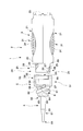
- the container for application which is a container according to the present embodiment is for applying, for example, an adhesive B as an application, and includes a container body 1 for storing the adhesive and a cap for sealing the tip of the container body 1.
- the container body 1 includes a nozzle 6 serving as an application portion of an adhesive B filled in a tube T serving as a sealed portion housed in the housing portion 2 by pressing a push button 3 attached to the housing portion 2 with a finger or the like.
- the adhesive B can be applied to the object from the tip surface 68 of the nozzle 6.
- the tip of the nozzle 6 is sealed by the cap 7, thereby preventing the adhesive B from touching the outside air.
- the specific description of the configuration of the cap 7 will be described later together with the middle cap 5 and the like.
- the tube T includes, for example, a tube main body T1 formed in a state where an aluminum plate formed into a thin plate shape holds the adhesive B hermetically, and an attachment screw portion T2 formed into a male screw shape at one end of the tube main body T1.
- An extraction surface T3 that allows the adhesive B to be extracted to the outside in a state where the aluminum material is torn inside the mounting screw portion T2 by making the aluminum material thin at the one end side of the mounting screw portion T2. have.
- the configuration of the tube T is, for example, an existing one designed to hold the existing adhesive B, liquid or gel chemicals, and the like. That is, the tube T alone can be used as a container.
- the abdomen T4 formed in a planar shape so as to make the front and back surfaces of the tube body T1 face each other is pressed with a finger or the like, so that the applied material, that is, the adhesive B from the portion where the aluminum material of the extraction surface T3 is broken. Can be extracted outside the tube T.
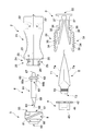
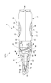
- the container main body 1 includes an inner cap 4 and a nozzle 6 mounted in the housing portion 2 in addition to the housing portion 2, the push button 3 and the nozzle 6. It has a middle cap 5 that is externally fitted to the accommodating portion 2 in a fixed state, and is assembled by appropriately assembling them.
- the cap 7 includes a protrusion 74 that is inserted along the axial direction in which the nozzle 6 extends to the tip of the nozzle 6 in a state where the container body 1 is closed, and the protrusion An inclined rising surface 75 is provided, in which a rising portion where 74 rises is inclined with respect to the axis of the nozzle 6 extending.
- the configuration of the cap 7 will be described in detail later.
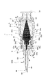
- the housing portion 2 is integrally molded of resin, for example, and has a so-called halved structure that is symmetrically molded via a resin hinge provided on the base end side opposite to the tip end where the nozzle 6 is positioned. Is. That is, the accommodating part 2 is hold
- the housing portion 2 is formed by opening a position corresponding to the center in both the longitudinal direction and the width direction so that the push button 3 can be exposed, and a groove for holding the push button 3 on the inner surface side and in the vicinity of the proximal end.
- the middle cap mounting portion 24 includes an engagement guide portion 25 to be described later, a separation guide portion 201 for separating the middle cap 5 at the time of sorting and discarding, and a separation guide portion 202 for guiding the separation guide portion to the separation guide portion. It is what has.
- the disengagement guide portion 201 is a groove extending in the longitudinal direction of the middle cap attachment portion 24 provided in the vicinity of the engagement guide portion 25.
- the disengagement guiding portion 202 is a rounded surface obtained by processing the surface from the engagement guide portion 25 to the disengagement guide portion 201 into a curved surface.
- the press button 3 has a symmetrical shape integrally formed of, for example, an elastic resin.
- the button main body 31 that is directly pressed by the user and the tube main body T1 that is pressed by the button main body 31 in detail.
- the pressing plate 32 that can press the flat abdomen T4 from one side and the other side with uniform strength, and the paired button body 31 and pressing plate 32 can be operated by the elasticity of the resin.
- a base end portion 33 that is exposed on the base end side of the housing portion 2. More specifically, the button main body 31 is curved at the proximal end side of the operation portion 34 and the operation portion 34 formed in an uneven shape in which a plurality of ribs are arranged at equal intervals so that a finger or the like can be easily picked without slipping.
- the pressing plate 32 protrudes in the opposite direction from the vicinity of the distal end portion, and the transmission rib 35 that can come into contact with the button main body 31 at the protruding end portion and the other end of the tube T at the proximal end portion are sandwiched and are preferential because they are thin.
- a sandwiching hinge 37 that can be curved.
- the push button 3 forms a pair of button main bodies 31 attached to the accommodating portion 2 that accommodates the tube T, and presses the button main body 31. It has a pressing plate 32 that forms a pair that is pressed and is in close contact with the abdomen T4 of the tube T.
- the pressing plate 32 presses the abdomen T4 of the tube T in a planar shape from the other end side, which is the opposite side of the extraction surface T3, to the one end side, which is the extraction surface T3 side.
- the tube T is sequentially pressed in a planar shape from the other end side toward one end side where the extraction surface T3 is provided.
- the adhesive B which is the contents in the tube T is stably extracted without waste.
- the contact position between the transmission rib 35 provided on the pressing plate 32 and the button main body 31 during the pressing operation slightly changes from the other end side to the one end side. Thereby, even if it is a tube with few remaining amount of adhesives B as shown in FIG.
- the inner cap 4 is for fixing the tube T inside the housing portion 2, and is inserted into the female screw portion 41 screwed to the mounting screw portion T 2 of the tube T and the inner cap mounting portion 23 of the housing portion 2. And a nozzle contact portion 43 that contacts the nozzle 6 and positions the nozzle 6 in the longitudinal direction.
- irregularities are formed on the outer peripheral surface of the mounting flange 42 so that the inner cap 4 can be smoothly screwed to the tube T. Further, the unevenness of the outer peripheral surface is engaged with a projection (not shown) provided on the inner surface of the inner cap mounting portion 23 when accommodated in the inner cap mounting portion 23, and prohibits relative rotation during mounting.
- the middle cap 5 is provided with a liquid dripping prevention part 50 at the tip, and can effectively avoid the problem that the adhesive B spilled from the nozzle 6 falls.
- the inner cap 5 forms an uneven knurl 5a (FIG. 11) on a part of the surface, and an outer fitting portion 51 that can cover the inner cap mounting portion 23 of the housing portion 2 from the outside, and a surface described later.
- the screw portion 8 screwed into the cap 7, the nozzle mounting portion 53 having the positioning groove 57 for fixing the nozzle 6 in the axial direction, And an opening (not shown) in which a part of the fitting portion 51 is opened.
- the outer fitting portion 51 has a rotation engagement claw 55 that can be engaged with the middle cap mounting portion 24 inward.
- the rotation engaging claw 55 is extended in the circumferential direction by appropriately cutting out the resin material, and protrudes inward at the tip of the extending portion 58, with respect to the middle cap mounting portion 24.
- an engagement end 59 for direct engagement.
- the nozzle 6 is integrally formed of a transparent or translucent resin so that the presence or absence of the internal adhesive B can be easily understood.
- the nozzle 6 includes a nozzle main body 61 that is exposed from the housing portion 2, a mounted portion 62 that is attached to the middle cap 5, and an extraction pipe 63 that extracts the adhesive B on the proximal side of the mounted portion 62. And have.
- the nozzle body 61 has an inclined tip portion 64 that forms a tip surface 68 by notching the tip end side in an inclined direction, and a tapered portion 69 formed so that the outer diameter gradually decreases until reaching the inclined tip portion 64. is doing.
- the mounted portion 62 includes a flange 65 positioned in the longitudinal direction of the middle cap 5, two large and small positioning ribs 66 a and 66 b that prohibit rotation around the axis and determine a relative angle with respect to the middle cap 5.
- the inclined tip portion 64 of the nozzle 6 forms a tip surface 68 by cutting the nozzle body 61 in an oblique direction.
- Such a front end surface 68 presents an obliquely flat cut surface in the nozzle body 61.
- the nozzle 6 makes the front-end
- variety of the adhesive agent B can be changed arbitrarily.
- the nozzle 6 has a directional shape.
- tip part 64 is set to 0.3 mm or less, and the amount of the adhesive agent B apply
- the container body 1 engages the accommodating portion 2 and the nozzle 6 with the nozzle 6 and the inner cap 5 being unable to apply the adhesive B.
- the first engaging position (P) and the nozzle 6 in which the accommodating portion 2 and the nozzle 6 have a predetermined direction from the first engaging position (P) apply the adhesive B.
- the housing portion 2 and the nozzle 6 can be engaged with each other at a second engagement position (Q) to be engaged so as not to be relatively movable in the obtained state, and the second engagement position (P) can be engaged with the second from the first engagement position (P).
- An engagement guide portion 25 that can guide the operation to the engagement position (Q), a disengagement guide portion 201 that can disengage the nozzle 6 and the middle cap 5 from the storage portion 2, and the second engagement position (Q). And a detachment guide part 202 for guiding the operation from the detachment guide part 201 to the detachment guide part 201. .
- the engagement guide portion 25 is provided in the middle cap attachment portion 24 of the housing portion 2, and the engagement guide portion 25 has a nozzle attachment portion 53 that can attach the nozzle 6 in a non-rotatable manner.
- the nozzle 6 is indirectly positioned to the first engagement position (P) and the second engagement position (Q) by engaging and guiding the rotary engagement claw 55 provided on the nozzle.
- the engagement guide portion 25 includes an introduction guide groove 26 for inserting the engagement end 59 and a first position for indirectly positioning the nozzle 6 at the first engagement position (P).
- the nozzle 6 is guided from the first engagement position (P) to the second engagement position (Q), so that the orientation of the nozzle 6 is suitable for use.
- a series of operations for setting the container body 1 to be usable while positioning the tube 6 and an operation for removing the nozzle 6 from the container 2 together with the middle cap 5 for separating and discarding the tube T will be described.
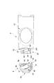
- FIG. 10 shows a mode in which the middle cap 5 to which the nozzle 6 is fixed is introduced toward the housing portion 2.
- the middle cap 5 is mounted in the cap 7 in such an operation. More specifically, the engagement end 59 of the rotation engagement claw 55 in the middle cap 5 is aligned with a position where it can be inserted into the introduction guide groove 26.
- the engagement end 59 is further moved to the base end side along the introduction guide groove 26 from this state, the engagement end 59 is fitted into the first engagement hole 27 and the first engagement position (P) is set.
- the base end of the nozzle 6, that is, the through end 67 of the extraction pipe 63 is separated from the extraction surface T3 of the tube T, so that the adhesive B can be injected into the nozzle 6. There is no state.
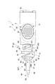
- the middle cap 5 is screw-fed so as to rotate the engagement end 59 along the rotation guide groove 28, the penetration end 67 passes through the extraction surface T3 and is inserted into the tube T while rotating.
- the screw feeding operation is performed so as to rotate 90 ° from the first engagement position (P)
- the engagement end 59 is inserted into the second engagement hole 29 as shown in FIG.
- the engagement end 59 is fitted deeply into the second engagement hole 29, so that the engagement cannot be released unless the external force greatly exceeds the normal operation force.
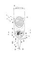
- a series of operations up to here are performed through the cap 7. Therefore, in a state where the engagement end 59 is fitted in the second engagement hole 29, the cap positioning portion 70 abuts against the cap stopper 20 of the housing portion, and further rotation is prohibited.
- the positioning rib 66 of the nozzle 6 is fitted in the positioning groove 57 and the rotation operation is prohibited, and the flange 65 contacts the nozzle contact portion 43 and the operation in the extending direction of the nozzle 6 is also prohibited.
- the nozzle 6 is indirectly fixed to the accommodating portion 2 at the second engagement position (Q).
- the tip surface 68 of the nozzle 6 is in the same direction as the direction in which the button main body 31 of the push button 3 attached to the accommodating portion 2 is exposed. That is, the direction in which the operation unit 34 is exposed matches the direction in which the tip surface 68 of the nozzle 6 faces. Therefore, the direction in which the abdomen T4 and the operation unit 34 of the tube body T1 are exposed matches the direction in which the tip surface 68 of the nozzle 6 faces. That is, the pressing operation of the tube T and the visual recognition of the discharge of the adhesive B from the distal end surface 68 are facilitated. Thereby, the user can easily recognize the direction of the distal end surface 68 from the direction in which the button body 31 is pressed.
- a detachment structure in which the middle cap 5 can be detached from the accommodating portion 2 is adopted. That is, the middle cap 5 can be removed from the housing portion 2 by further rotating the middle cap 5 from the second engagement position (Q). Such an operation is performed without using the cap 7, such as picking the knurl 5 a provided on the middle cap 5 with a finger.
- a detachment structure is not limited to the detachment of the middle cap 5 from the housing portion 2, and can be applied to other applications.
- the present embodiment it is a to-be-removed element formed so that the middle cap 5 that is the disengaging element can be further disengaged from the second engaging position (Q) that is the engaging position by operating the middle cap 5.
- a separation guide portion 201 formed in the housing portion 2 and a separation guide portion 202 for guiding the engagement guide portion 201 to the separation guide portion 201 are provided. More specifically, when the knurling 5a provided on the surface of the middle cap 5 is picked and rotated further from the second engagement position (Q) shown in FIGS. 11 and 12, the state shown in FIG. Become. In this state, the engagement end 59 comes out of the second engagement hole 29 and is guided to the separation guide portion 202 so as to substantially contact the groove-shaped separation guide portion 201 extending to the upper end of the middle cap mounting portion 24. Take the position that can be removed.
- the middle cap 5 when the middle cap 5 is pulled from a state where the engaging end 59 is in contact with the separation guide portion 201 having a groove shape, the middle cap 5 can be detached from the housing portion 2 with a small force as shown in FIG. And the used tube T is taken out from the accommodating part 2 which removed the middle cap 5.
- the above-described detachment structure with the middle cap 5 as the detachable element and the accommodating portion 2 as the detachable element can be adopted as the structure of other various assembled products.
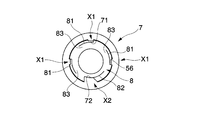
- the screw portion 8 includes a first screw groove 81 that is a single screw groove provided on the surface of the middle cap 5, and a second screw groove 82 that is deeper than the first screw groove 81 and has a larger width dimension.
- a step portion 83 provided at a portion other than the start end portion of the second screw groove including the start end portion of the first screw groove 81, and a step provided near the end of the second screw groove 82.
- an overpass portion 84 which is The second screw groove 82 is a single groove formed at a position where the angular phase is 180 ° different from that of the first screw groove.
- the ride-over portion 84 is When the second convex portion (not shown) of the cap 7 is exceeded, a click feeling is given to the user to let the user know that the second convex portion is approaching the end of the operation.
- the step portion 83 is a portion formed so that the outer diameter of the first end portion of the first screw groove 81 is increased by the difference in depth between the first screw groove 81 and the second screw groove 82. When the second convex portion comes into contact with the step portion 83, screwing of the cap 7 to the screw portion 8 is prohibited.
- the cap 7 is screwed so as to cover the front end side of the container body 1 so as to cover the nozzle 6.
- the cap 7 is formed, for example, by integral molding of a resin, and includes a first convex portion 71 and a second convex portion (not shown) formed by protruding the resin on the inner surface side, and an edge portion at the base end side edge portion.
- a positioning portion 70 formed in a step shape, four sliding contact ribs 73 extending in the longitudinal direction in the vicinity of the distal end inside the cap 7 and capable of slidingly contacting the outer surface of the nozzle 6, and the proximal end from the inner surface of the distal end portion of the cap 7. It has a protruding portion 74 that protrudes in a cylindrical shape toward the side and can be inserted into the nozzle 6, and an inclined rising surface 75 that is a bottom surface on which the protruding portion 74 rises.
- the 1st convex part 71 is the 1986
- a second convex part (not shown) is formed at a position facing the first convex part 71, and corresponds to the depth dimension and the width dimension in which the second screw groove 82 is formed, that is, the first convex part.
- the positioning unit 70 can effectively hold the end position (Q1) by contacting the container body 1 side at the end position (Q1).
- the positioning portion 70 abuts against the cap 7 stopper provided in the housing portion, not the middle cap 7 in the container body 1. As a result, even if the user screws the cap 7 with a strong force, the acting force does not affect the middle cap 5.
- the sliding contact ribs 73 are provided at four equal intervals in the circumferential direction inside the cap 7, and the end positions (Q 1) are formed by inclining the tips according to the angle of the taper portion of the nozzle 6. It is slidably contacted with the taper part at the time of screwing up to, and plays the role of scraping off the adhesive B adhering to the taper part.
- the protrusion 74 is inserted so as to plug the inclined tip portion without a gap at the end position (Q1), so that the adhesive B in the nozzle 6 comes into contact with the outside air and is fixed at the end position (Q1). This is to avoid this.
- the projecting portion 74 has an inclined end 74a formed so as to face the forward / backward direction of the screwing, that is, the direction of the axis from the tip portion inside the cap 7 in an inclined direction. Due to the inclined end 74 a, the projecting portion 74 is configured not to interfere with the shape of the inclined tip end portion 64 of the nozzle 6.
- screwing always starts from a start position (P1) that is at a single relative position, regardless of the direction in which the user rotates the cap 7. Similarly, screwing ends at a single end position (Q1).
- the second convex portion rotates while being blocked by the step portion 83.
- the step portion 83 is also formed at the starting end of the first screw groove 81, the second convex portion is not erroneously inserted into the first screw groove 81.
- the 1st convex part 71 and the 2nd convex part enter in the 1st thread groove and the 2nd thread groove 82, it is the starting position (P1) shown in FIG. 15, and screwing is started from here.
- the protrusion 74 is in a state in which the inclined end 74a faces the front of the drawing, and has not yet contacted the inclined tip 64.
- the first convex portion 71 and the second convex portion proceed through the first screw groove 81 and the second screw groove 82, respectively, as shown in FIG.
- the tip surface 68 of the nozzle 6 facing diagonally upward and the inclined end 74a of the projecting portion 74 facing diagonally downward face each other, and The contact is slightly made, and the insertion of the inclined end 74a into the inclined tip portion 64 starts from here.
- the inclined tip portion 64 is set to have a thin material thickness of 0.3 mm, there may be some distortion and bending from the state shown in the figure, but the protrusion 74 is inserted to Bending will be corrected.
- the 1st convex part 71 and the 2nd convex part advance the inside of the 1st thread groove 81 and the 2nd thread groove 82, and rotate 180 degrees from the start position (P1), the cap 7 is the end position (Q1 shown in FIG. 17).
- the end position (Q1) of the cap 7 the first convex portion 71 and the second convex portion do not contact the terminal ends of the first screw groove 81 and the second screw groove 82.
- the tip surface 68 is in a state of being in close proximity to the inclined rising surface 75 and is in a state facing the back in the orientation illustration of the inclined end 74a, that is, the direction of the tip surface 68 has a 90 ° phase. It is in a different state.
- tip part 64 is made small, and the influence on the protrusion part 74 by the adhesive agent B at the time of opening the cap 7 is suppressed to the minimum.
- the rising area of the protrusion 74 is inclined from the axial direction, specifically, from the virtual plane orthogonal to the axial direction. Therefore, the area is larger than the cross-sectional area from the angle orthogonal to the axial direction of the protrusion 74 itself. As a result, the protruding portion 74 can be raised with a larger area, and the strength of the rising portion is particularly high. Thereby, the cap 7 which can hardly be damaged by the adhesive B and can stably cover the container main body 1, that is, the inclined tip portion 64 of the nozzle 6, is realized.
- the inclined tip portion 64 of the nozzle 6 is applied. Secure positioning of the protrusion 74 is ensured.
- the tip of the protrusion 74 is formed as an inclined end, so that it can be smoothly inserted into the inclined tip 64 while avoiding interference with the nozzle 6 during screwing.
- the protrusion 74 is formed into a thin wall that is difficult to secure the shape as in the same embodiment by realizing easy and reliable insertion of the protrusion 74 into the inclined tip 64. Even with respect to the inclined tip portion 64 set to 0.3 mm or less, the shape of the inclined tip portion 64 is effectively secured by inserting the protruding portion 74 easily and reliably.
- the container for application is, for example, for applying an adhesive B as an application, and includes a container body 1 that contains the adhesive and a cap 7 that seals the tip of the container body 1.
- the container body 1 includes a nozzle 6 serving as an application portion of an adhesive B filled in a tube T serving as a sealed portion housed in the housing portion 2 by pressing a push button 3 attached to the housing portion 2 with a finger or the like.
- the adhesive B can be applied to the object from the tip surface 68 of the nozzle 6.
- the tip of the nozzle 6 is sealed by the cap 7 as shown in FIG. 20, thereby preventing the adhesive B from touching the outside air.
- the specific description of the configuration of the cap 7 will be described later together with the middle cap 5 and the like.
- the tube T includes, for example, a tube main body T1 formed in a state where an aluminum plate formed into a thin plate shape holds the adhesive B hermetically, and an attachment screw portion T2 formed into a male screw shape at one end of the tube main body T1.
- An extraction surface T3 that allows the adhesive B to be extracted to the outside in a state where the aluminum material is torn inside the mounting screw portion T2 by making the aluminum material thin at the one end side of the mounting screw portion T2. have.
- the configuration of the tube T is, for example, an existing one designed to hold the existing adhesive B, liquid or gel chemicals, and the like. That is, the tube T alone can be used as a container.
- the abdomen T4 formed in a planar shape so as to make the front and back surfaces of the tube body T1 face each other is pressed with a finger or the like, so that the applied material, that is, the adhesive B from the portion where the aluminum material of the extraction surface T3 is broken. Can be extracted outside the tube T.
- the container body 1 includes, as its constituent parts, an inner cap 4 and a nozzle 6 mounted in the housing portion 2 in addition to the housing portion 2, the push button 3 and the nozzle 6. It has a middle cap 5 that is externally fitted to the accommodating portion 2 in a fixed state, and is assembled by appropriately assembling them.
- the container main body 1 is configured to apply the adhesive B accommodated in the accommodating part 2 that accommodates the adhesive B and has a directionality to the object.
- a container body 1 having a nozzle 6 formed with an inclined tip 64 having a directivity and attached to the housing portion 2, wherein the nozzle 6 cannot apply the adhesive B.
- the first engaging position (P) for engaging the accommodating portion 2 and the nozzle 6, and the accommodating portion 2 and the nozzle 6 have a predetermined direction from each other from the first engaging position (P). None and the second engaging position (Q) in which the nozzle 6 can be applied with the adhesive B so that the nozzle 6 can be applied with the adhesive B, the housing portion 2 and the nozzle 6 can be engaged with each other. Movement from one engagement position (P) to the second engagement position (Q) And characterized by being provided with an engaging guide portion 25 that can guide the.
- the screwing structure X applied to the container main body 1 and the cap 7 includes the first screw groove 81 provided in the container main body 1 that is a member to be screwed, and the first screw groove.
- the container body 1 and the cap 7 are provided on a cap 7 that can be screwed onto a container body that can be inserted, and the container body 1 and the cap 7 are rotated relative to each other from a start position (P1) that forms a predetermined relative angle.
- a first threaded portion X1 having a first convex portion 71 provided for screwing at an end position (Q1) forming an angle, and a recess deeper than the first screw groove 81 are provided in the container body 1.
- the second screw groove 82 and the second convex portion 72 provided on the cap 7 so as to be inserted and screwed only into the predetermined second screw groove 82 and not to be inserted into the first screw groove 81 are provided. It has the 2nd screwing part X2 which has. The screw structure X will be described in detail later.
- the housing portion 2 is integrally molded of resin, for example, and has a so-called halved structure that is symmetrically molded via a resin hinge provided on the base end side opposite to the tip end where the nozzle 6 is positioned. Is. That is, the accommodating part 2 is hold
- the housing portion 2 is formed by opening a position corresponding to the center in both the longitudinal direction and the width direction so that the push button 3 can be exposed, and a groove for holding the push button 3 on the inner surface side and in the vicinity of the proximal end.
- a button mounting portion 22 an inner cap mounting portion 23 that is a groove for holding the inner cap 4 on the inner surface side and in the vicinity of the tip, and a middle cap mounting portion 24 to which the middle cap 5 can be fitted.
- this outer cap attaching part 24 has the engagement guide part 25 which concerns on this embodiment, The detailed structure of the said engagement guide part 25 is explained in full detail behind.
- the press button 3 has a symmetrical shape integrally formed of, for example, an elastic resin.
- the button main body 31 that is directly pressed by the user and the tube main body T1 that is pressed by the button main body 31 in detail.
- the pressing plate 32 that can press the flat abdomen T4 from one side and the other side with uniform strength, and the paired button body 31 and pressing plate 32 can be operated by the elasticity of the resin.
- a base end portion 33 that is exposed on the base end side of the housing portion 2.
- the button main body 31 is close to the operation portion 34 formed in a concavo-convex shape in which a plurality of ribs are arranged at equal intervals so that a finger or the like can be easily picked without slipping, and the proximal end side of the operation portion 34. It has a transmission rib 35 that protrudes in the direction and can come into contact with the pressing plate 32 at the protruding end.
- the inner cap 4 is for fixing the tube T inside the housing portion 2, and is inserted into the female screw portion 41 screwed to the mounting screw portion T 2 of the tube T and the inner cap mounting portion 23 of the housing portion 2. And a nozzle contact portion 43 that contacts the nozzle 6 and positions the nozzle 6 in the longitudinal direction.
- irregularities are formed on the outer peripheral surface of the mounting flange 42 so that the inner cap 4 can be smoothly screwed to the tube T.
- the middle cap 5 is provided with a liquid dripping prevention part 50 at the tip, and can effectively avoid the problem that the adhesive B spilled from the nozzle 6 falls.
- this inner cap 5 forms the external fitting part 51 which can cover the inner cap attaching part 23 of the accommodating part 2 from the outer side, and the 1st thread groove 81 and the 2nd thread groove 82 which are the thread surfaces 56 which are mentioned later on the surface.
- the screw portion 8 screwed to the cap 7, the nozzle mounting portion 53 having the positioning groove 57 for fixing the nozzle 6 in the axial direction, and the opening portion 54 in which a part of the outer fitting portion 51 is opened. have.
- the outer fitting portion 51 has a rotation engagement claw 55 that can be engaged with the middle cap mounting portion 24 inward.
- the rotation engaging claw 55 is extended in the circumferential direction by appropriately cutting out the resin material, and protrudes inward at the tip of the extending portion 58, with respect to the middle cap mounting portion 24. And an engagement end 59 for direct engagement.
- a specific configuration of the screw portion 8 will be described in detail later.
- the nozzle 6 is integrally formed of a transparent or translucent resin so that the presence or absence of the internal adhesive B can be easily understood.
- the nozzle 6 includes a nozzle main body 61 that is exposed from the housing portion 2, a mounted portion 62 that is attached to the middle cap 5, and an extraction pipe 63 that extracts the adhesive B on the proximal side of the mounted portion 62. And have.
- the nozzle body 61 has an inclined tip portion 64 that forms a tip surface 68 by notching the tip end side in the inclined direction, and a tapered portion 69 that is formed so that the outer diameter gradually decreases until reaching the inclined tip portion. ing.
- the mounted portion 62 has a flange 65 positioned in the longitudinal direction with respect to the middle cap 5 and a protruding positioning rib 66 for prohibiting rotation around the axis.
- the inclined tip portion 64 of the nozzle 6 forms a tip surface 68 by cutting the nozzle body 61 in an oblique direction.
- Such a front end surface 68 presents an obliquely flat cut surface in the nozzle body 61.
- the nozzle 6 makes the front-end
- the container main body 1 has the first engagement position (P) in which the nozzle 6 is engaged with the housing portion 2 and the nozzle 6 in a state where the adhesive B cannot be applied. And the accommodating portion 2 and the nozzle 6 from the first engagement position (P) are engaged with each other so that the nozzle 6 can apply the adhesive B in a state in which the nozzle 6 has a predetermined direction.
- the accommodating portion 2 and the nozzle 6 can be engaged with each other at the second engagement position (Q), and the operation from the first engagement position (P) to the second engagement position (Q) is performed. It is provided with the engagement guide part 25 which can guide.
- the engagement guide portion 25 is provided in the outer cap attachment portion 24 of the housing portion 2, and the engagement guide portion 25 has the nozzle cap portion 53 that can attach the nozzle 6 in a non-rotatable manner.
- the nozzle 6 is indirectly positioned to the first engagement position (P) and the second engagement position (Q) by engaging and guiding the rotary engagement claw 55 provided on the nozzle.
- the engagement guide portion 25 includes an introduction guide groove 26 for inserting the engagement end 59 and a first position for indirectly positioning the nozzle 6 at the first engagement position (P).
- the rotation guide groove 28 that is a groove continuous from the first engagement hole 27 in the screw feeding direction, and the engagement end 59 is positioned so as not to move by being guided by the rotation guide groove 28.
- a second engagement hole 29 for indirectly fixing the nozzle 6 to the second engagement position (Q).
- the nozzle 6 is guided from the first engagement position (P) to the second engagement position (Q) so that the orientation of the nozzle 6 is suitable for use.
- a series of operations for setting the container main body 1 in a usable state while positioning to the position will be described.
- FIG. 23 shows a mode in which the middle cap 5 to which the nozzle 6 is fixed is introduced toward the housing portion 2. Specifically, the engagement end 59 of the rotation engagement claw 55 is adjusted to a position where it can be inserted into the introduction guide groove 26. When the engagement end 59 is further moved to the proximal end side along the introduction guide groove 26 from this state, the first engagement position (P) shown in FIGS. 25 and 27 is taken. In this first engagement position (P), the base end of the nozzle 6, that is, the through end 67 of the extraction pipe 63 is separated from the extraction surface T3 of the tube T, so that the adhesive B can be injected into the nozzle 6. There is no state.
- the middle cap 5 when the middle cap 5 is screw-fed so as to rotate the engagement end 59 along the rotation guide groove 28 from the state shown in FIG. 25, the penetration end 67 passes through the extraction surface T3 while rotating through the tube T. Is inserted.
- the screw feeding operation when the screw feeding operation is performed so as to rotate 90 ° from the first engagement position (P), the engagement end 59 is inserted into the second engagement hole 29 as shown in FIGS. Is done. In this state, the engagement end 59 is fitted deeply into the second engagement hole 29, so that the engagement cannot be released unless the external force greatly exceeds the normal operation force.
- the positioning rib 66 of the nozzle 6 is fitted in the positioning groove 57 and the rotation operation is prohibited, and the flange 65 contacts the nozzle contact portion 43 and the operation in the extending direction of the nozzle 6 is also prohibited.
- the nozzle 6 is indirectly fixed to the accommodating portion 2 at the second engagement position (Q).
- the front end surface 68 of the nozzle 6 has faced the same direction as the direction which the button main body 31 of the press button 3 attached to the accommodating part 2 exposes. . That is, the direction in which the operation unit 34 is exposed matches the direction in which the tip surface 68 of the nozzle 6 faces. Therefore, the direction in which the abdomen T4 and the operation unit 34 of the tube body T1 are exposed matches the direction in which the tip surface 68 of the nozzle 6 faces. That is, the pressing operation of the tube T and the visual recognition of the discharge of the adhesive B from the distal end surface 68 are facilitated. Accordingly, the user can easily recognize the direction of the distal end surface 68 from the direction in which the button body 31 is pressed, and can apply the adhesive B in a state in which the user can easily grasp it.
- the screwing structure X is realized by the screw portion 8 and the cap X provided in the middle cap 5.
- the screw portion 8 includes a first screw groove 81 that is a single screw groove provided on the surface of the middle cap 5, and a second screw groove 82 that is deeper than the first screw groove 81 and has a larger width dimension.
- a step portion 83 provided at a portion other than the start end portion of the second screw groove including the start end portion of the first screw groove 81, and a step provided near the end of the second screw groove 82.
- an overpass portion 84 which is The second screw groove 82 is a single groove formed at a position where the angular phase is 180 ° different from that of the first screw groove.
- the ride-over portion 84 is When the second convex portion 72 is exceeded, a click feeling is given to the user, so that the second convex portion 72 is approaching the end of the operation.
- the step portion 83 is a portion formed so that the outer diameter of the first end portion of the first screw groove 81 is increased by the difference in depth between the first screw groove 81 and the second screw groove 82. When the second convex portion 72 comes into contact with the step portion 83, screwing of the cap 7 to the screw portion 8 is prohibited.
- the cap 7 is screwed so as to cover the front end side of the container body 1 so as to cover the nozzle 6.
- the cap 7 is formed by integral molding of resin, for example, and includes a first convex portion 71 and a second convex portion 72 formed by protruding the resin on the inner surface side, and a stepped shape at the edge at the base end side edge.
- the formed positioning portion 70 for example, four sliding contact ribs 73 that extend in the longitudinal direction in the vicinity of the distal end inside the cap 7 and can come into sliding contact with the outer surface of the nozzle 6, and toward the proximal end side from the inner surface of the distal end portion of the cap 7.
- the 1st convex part 71 is the protrusion protruded in the substantially rectangular shape corresponding to the depth dimension and width dimension in which said 1st screw groove 81 is formed.
- the second convex part 72 is formed at a position facing the first convex part 71, and corresponds to the depth dimension and the width dimension in which the second screw groove 82 is formed, that is, from the first convex part 71. Furthermore, by projecting into a rectangular shape having a large projecting dimension and projecting area, the second thread groove 82 can be inserted without rattling.
- the positioning unit 70 can effectively hold the end position (Q1) by contacting the container body 1 side at the end position (Q1).
- the positioning portion 70 abuts against the cap stopper 20 provided in the housing portion, not the middle cap 7 in the container body 1.
- the sliding contact ribs 73 are provided at four equal intervals in the circumferential direction inside the cap 7, and the end positions (Q 1) are formed by inclining the tips according to the angle of the taper portion of the nozzle 6. It is slidably contacted with the taper part at the time of screwing up to, and plays the role of scraping off the adhesive B adhering to the taper part.
- the insertion rib 74 is inserted so as to plug the inclined tip portion without a gap at the end position (Q1), so that the adhesive B in the nozzle 6 comes into contact with the outside air and is fixed at the end position (Q1). This is to avoid this.
- the first screw groove 81 and the first convex portion 71 described above constitute the first threaded portion X1 of the present embodiment
- the second screw groove 82 and the second convex portion 72 are the present embodiment.
- the 2nd screwing part X2 is comprised.
- the second convex portion 72 is blocked by the step portion 83 as shown in FIG. Rotate in the state.
- the step portion 83 is also formed at the starting end of the first screw groove 81, the second convex portion 72 is not erroneously inserted into the first screw groove 81.
- the 2nd convex part 72 has started the 2nd thread groove 82, it is a start position (P1) shown in FIG. 36, and screwing is started from here.
- the first convex portion 71 is also inserted into the first screw groove 81.
- the first convex portion 71 and the second convex portion 72 advance in the first screw groove 81 and the second screw groove 82, respectively, as shown in the upper and middle stages of FIGS. .
- the 1st convex part 71 and the 2nd convex part 72 advance in the 1st thread groove 81 and the 2nd thread groove 82, and rotate 180 degrees from the start position (P1), the cap 7 is positioned in the end position (Q1). Is done.
- the first convex portion 71 and the second convex portion 72 are not in contact with the terminal ends of the first screw groove 81 and the second screw groove 82 at the end position (Q1).
- the positioning part 70 provided at a location different from the second convex part 72 abuts not the screw part but the cap stopper 20 provided on the container 2 side of the container body 1.
- the container body 1 applies the adhesive B accommodated in the accommodating part 2 that accommodates the adhesive B and has the directionality, and the adhesive B accommodated in the accommodating part 2 to the object.
- the container 2 and the nozzle 6 can be engaged with each other at a second engagement position (Q) in which the nozzle 6 can be applied with the adhesive B so that the nozzle 6 can be applied without relative movement. From the first engagement position (P) to the second engagement position (Q) And characterized by being provided with an engaging guide portion 25 that can guide the operation.
- the container body 1 according to the present embodiment can be stored, shipped, transported, etc., as long as the nozzle 6 is engaged with a desired position, that is, the first engagement position (P). It is possible to maintain a state in which the adhesive B, which is a coating material, cannot be leaked or applied by mistake.
- the guide can be accurately guided from the first engagement position (P) to the second engagement position (Q) by the engagement guide portion 25, the user can easily use the container body 1.
- the adhesive agent B can be apply
- the relative movement between the accommodating portion 2 and the nozzle 6 is prohibited at the second engagement position (Q), the user can suitably perform the application work.
- the engagement guide portion 25 is rotated relative to the nozzle 6 and the storage portion 2. It is assumed that the second engagement position (Q) is guided by performing a screw feeding operation.
- the inclined tip portion 64 of the nozzle 6 is positioned according to the orientation of the accommodating portion 2, so that the user can easily adjust the orientation of the nozzle 6 and suitably apply the adhesive B. It is said.
- the accommodating part 2 accommodates the adhesive B by accommodating the tube T in which the adhesive B is sealed, and the base end of the nozzle 6 at the second engagement position (Q). It is assumed that the extraction tube 63 located in can be inserted into the tube T.
- a button that can supply the adhesive B to the nozzle 6 when the storage portion 2 is pressed.
- the direction of the nozzle 6 and the supply amount of the adhesive B can be freely adjusted by aligning the direction of the inclined tip 64 in the direction in which the button is exposed from the housing 2. It has become.
- the screwing structure X applied to the container main body 1 and the cap 7 includes the first screw groove 81 provided in the container main body 1 that is a member to be screwed, and the first screw groove.
- a cap 7 that is a screwed body that can be screwed into the container main body 1 that can be inserted is relatively rotated from a start position (P) that forms a predetermined relative angle.
- a first threaded portion X1 having a first convex portion 71 provided to be screwed in an end state (Q) having a relative angle, and a recess deeper than the first screw groove 81, are formed in the container body 1.
- the second screw groove 82 provided and the second protrusion 72 provided in the cap 7 so as to be inserted and screwed only into the predetermined second screw groove 82 and not to be inserted into the first screw groove 81. It has the 2nd screwing part X2 which has.
- the 2nd convex part 72 becomes a structure which can be inserted only in the predetermined
- the length dimension of the second convex portion 72 protruding in the inner direction of the cap 7 is set.
- the first convex portion 71 is set to be larger than the length dimension from which the first convex portion 71 protrudes, and the width dimension of the second thread groove 82 and the dimension of the second convex portion 72 corresponding to the width dimension are set to the first thread groove 81. It is set larger than the width dimension.
- the step 83 is provided at the insertion end for inserting the first convex portion at the start position (P1) in the first thread groove 81, the second convex portion 72 interferes with the first thread groove 81.
- the cap 7 and the container body 1 are smoothly rotated relatively until the second screw groove 82 is reached without causing the user to feel uncomfortable when the second convex portion 72 passes through the first screw groove 81. There is no.
- first screwing portion X1 and the second screwing portion X2 are provided at positions that face each other in order to achieve both a simple configuration and accurate screwing. Further, the first screwing portion X1 and the second screwing portion X2 are opposed to each other, that is, the 180 ° angle phase is varied to effectively avoid a partial strength variation.
- a positioning portion 70 for positioning the container body 1 and the cap 7 at the end position (Q1) at a position different from the first screwing portion X1 and the second screwing portion X2 Even if an acting force in the direction of further screwing is applied from the end position (Q1), it is effectively avoided that unnecessary force is applied to the first screwing portion X1 and the second screwing portion X2.
- FIG. 41 shows the first threaded portion X1 and the second threaded portion X2 provided at the same angle phase as in the above embodiment, but the size of the inner surface of the cap 7 from which the first convex portion 71 projects is shown in FIG. The same ⁇ as that of the biconvex portion 72 is set. Even if it is such, there exists an effect
- first screwing portions X1 are provided, that is, two and three.
- the second convex portion 72 can enter the first thread groove 81 as in the above embodiment. Therefore, the second protrusion 72 can be inserted into the second screw groove 82 at the exact start position (P1) as in the above embodiment. That is, in the screwing structure X according to the present embodiment, the number and arrangement of the first screwing portions X1 can be variously changed.
- the container main body 10 is flat in the direction of the front end surface 68 of the nozzle 6 and the direction of the button main body 31a exposed from the accommodating portion 2 at the second engagement position (Q) as in the above embodiment.
- the engagement guide portion 25a has the second engagement in the direction in which the nozzle 6 and the accommodating portion 2 are joined from the first engagement position (P). A mode of guiding to the matching position (Q) is applied.
- the configuration of the container body 10 will be mainly described in the configuration different from the above embodiment.
- the inner cap 4, the nozzle 6, the tube T, and the cap 7 have substantially the same configuration as that of the above embodiment, and thus detailed description thereof is omitted.
- the housing portion 2 has a substantially halved structure having a button hole 21, a button attachment portion 22, and an inner cap attachment portion 23 similar to the above embodiment, but the outer cap attachment portion 24a is an inner cap attachment portion.
- the push button 3 includes a pair of button main bodies 31a that are operatively connected to the base end portion 33.
- An operation portion 34a that can be directly operated by the button main body 31a and a tube main body directly on the back side of the operation portion 34a. It has a pressing surface 32a that can uniformly press the abdominal part T4 of T1, and the configuration of the pressing plate 32 in the above embodiment is omitted.
- the middle cap 5 has a configuration similar to that of the above embodiment with respect to the cover stopper 52 and the nozzle mounting portion 53, but the configuration of the opening 54 is omitted. And it has the insertion part 51a for mounting
- the insertion portion 51a has a total of four pressing engagement claws 55a protruding from the cover stopper 52 to the proximal end side.
- the pressing engagement claws 55a include an extension portion 58a extending to the proximal end side, It has an engagement end 59a that engages with the engagement guide portion 25a at the tip of the extension portion 58a.
- the engagement guide portion 25a is provided with the first engagement position (P) so as to facilitate the accurate positioning of the accommodating portion 2 and the nozzle 6 at the second engagement position (Q). ) To the second engagement position (Q) along the direction in which the nozzle 6 and the accommodating portion 2 are joined is applied.
- the engagement guide portion 25a is a first engagement hole for inserting the engagement end 59a and indirectly positioning the nozzle 6 at the first engagement position (P).
- a pressing guide groove 28a that is a groove that continues linearly from the first engagement hole 27a, and the engagement end 59a that is guided by the pressing guide groove 28a is positioned so as to be immovable.
- a second engagement hole 29a that is indirectly fixed to the second engagement position (Q).
- the nozzle 6 is guided from the first engagement position (P) to the second engagement position (Q), so that the orientation of the nozzle 6 is suitable for use.
- a series of operations for setting the container main body 10 to be usable while positioning to the position will be described.
- FIG. 48 shows a mode in which the middle cap 5 to which the nozzle 6 is fixed is introduced toward the housing portion 2. Specifically, the engagement end 59a of the press engagement claw 55a is engaged with the first engagement hole 27a which is the first engagement position (P). In this first engagement position (P), the base end of the nozzle 6, that is, the through end 67 of the extraction pipe 63 is separated from the extraction surface T3 of the tube T, so that the adhesive B can be injected into the nozzle 6. There is no state.
- the positioning rib 66 of the nozzle 6 is fitted in the positioning groove 57 and the rotation operation is prohibited, and the flange 65 contacts the nozzle contact portion 43 and the operation in the extending direction of the nozzle 6 is also prohibited.
- the nozzle 6 is indirectly fixed to the accommodating portion 2 at the second engagement position (Q).
- the front end surface 68 of the nozzle 6 is in the state which faced the same direction as the direction which the button main body 31a of the press button 3 attached to the accommodating part 2 exposes. . Thereby, the user can apply the adhesive B in a state in which the direction of the front end surface 68 can be easily grasped from the direction in which the button body 31a is pressed.
- the nozzle 6 is preferably positioned to the second engagement position (Q). Ten comfortable uses are guaranteed.
- the aspect in which the cap is mounted by screwing back and forth is disclosed, but of course, the aspect in which the cap is inserted along the axial direction may be used.
- the specific aspect of a nozzle, a tube, or a press button is not limited to the thing of the said embodiment, The thing of various aspects including an existing thing is applicable.
- the present invention can be used as a container having a cap for plugging a container containing an adhesive.
Abstract
A cap (7) for an application container, which is a container relating to the present invention, is characterized by comprising: a protrusion (74) which is a rib inserted in the front end of a nozzle (6) along the axial direction while the container body (1) is closed by the cap, the axial direction being the direction in which the nozzle (6) extends; and a sloped rising plane (75) on which a rising portion from which the protrusion (74) rises is provided so as to be tilted relative to the direction in which the nozzle (6) extends. As a result of this configuration, the sloped front end section (64) of the nozzle can be stably closed by the cap in such a manner that the sloped front end section (64) is less likely to be damaged by an adhesive agent (B).
Description
本発明は、接着剤入りの容器に栓をするためのキャップを有した容器に関するものである。
The present invention relates to a container having a cap for plugging a container containing an adhesive.
従来、接着剤入りの容器本体と、容器本体を蓋止するためのキャップとを有する容器が種々提案されている。このようなもののうち、容器本体内で接着剤が硬化してしまうことを有効に回避するため、キャップで蓋止したときに接着剤が外気に触れることを避ける目的で、キャップの内面に突出部を設け、当該突出部をキャップ装着時に容器の先端に挿入させ、キャップを取付けた状態では接着剤が当該突出部によって外気に触れることを回避し得るという態様も提案されている。特にこのようなキャップは,容器の先端側に特殊な形状を有したノズルを配しているものに対しても有効であると思われる(例えば、特許文献1参照)。
Conventionally, various containers having a container body containing an adhesive and a cap for closing the container body have been proposed. Of these, in order to effectively avoid the adhesive from being hardened in the container body, a protruding portion is formed on the inner surface of the cap in order to prevent the adhesive from touching the outside air when the cap is closed with the cap. There is also proposed a mode in which the protrusion is inserted into the tip of the container when the cap is attached, and the adhesive can be prevented from touching the outside air by the protrusion when the cap is attached. In particular, such a cap seems to be effective even for a container in which a nozzle having a special shape is arranged on the tip side of the container (see, for example, Patent Document 1).
しかしながら、上記特許文献1のようなものであっても、キャップをする前の段階において既に外気に触れている接着剤に対してキャップに設けた突出部が触れる場合、接着剤が突出部に触れた状態で硬化が始まってしまうことも起こり得る。そうなると、次なる使用時にキャップを容器本体から取り外す際に突出部が接着剤から離れられず、その結果、突出部がキャップから離脱してしまうといった不具合が起こることも考えられる。
However, even if it is like the said patent document 1, when the protrusion part provided in the cap touches the adhesive agent which has already touched external air in the step before capping, an adhesive agent touches a protrusion part. Curing may begin in the wet state. In that case, when the cap is removed from the container main body in the next use, there is a possibility that the protrusion is not separated from the adhesive, and as a result, the protrusion is detached from the cap.
本発明は、このような不具合に着目したものであり、接着剤によって損傷し難く安定して容器本体を蓋止し得るキャップを有した容器を提供することを目的としている。
The present invention pays attention to such inconveniences, and an object of the present invention is to provide a container having a cap that can hardly be damaged by an adhesive and can stably cover the container body.
本発明は、このような目的を達成するために、次のような手段を講じたものである。
In the present invention, the following means are taken in order to achieve such an object.
すなわち本発明に係る容器は、接着剤を塗布するノズルを有する容器本体と、この容器本体に装着するキャップとを具備する容器であって、前記キャップが、前記ノズルの先端から前記ノズルの長手方向に沿って挿入される突出部と、当該突出部が立ち上がる立ち上がり箇所を前記ノズルの長手方向に対し傾斜して設けた傾斜立ち上がり面とを具備することを特徴とする。
That is, the container according to the present invention is a container comprising a container body having a nozzle for applying an adhesive and a cap attached to the container body, wherein the cap extends from the tip of the nozzle in the longitudinal direction of the nozzle. And a sloped rising surface in which a rising portion where the protruding portion rises is inclined with respect to the longitudinal direction of the nozzle.
このようなものであれば、突出部の立ち上がり面積は軸線方向から傾斜しているので突出部自体の軸線方向に直交する角度からの断面積よりも大きな面積となる。その結果突出部をより大きな面積で立ち上がらせることができるので、特に立ち上がり箇所の強度の高い突出部とすることができる。その結果、接着剤によって損傷し難く安定して容器本体を蓋止し得るキャップを有した容器を提供することが可能となる。
In such a case, since the rising area of the protruding portion is inclined from the axial direction, the area is larger than the cross-sectional area from an angle orthogonal to the axial direction of the protruding portion itself. As a result, the protruding portion can be raised with a larger area, so that the protruding portion having a particularly high strength at the rising portion can be obtained. As a result, it is possible to provide a container having a cap that is hard to be damaged by the adhesive and can stably cover the container body.
上記の突出部は高い強度をもってノズルの先端に挿入しているので、単にノズルの先端を好適に蓋止し得るのみならず、ノズルの先端が長手方向に対し傾斜方向に面するものに対しては、先端の形状を有効に担保し得る。
Since the above-mentioned protrusion is inserted at the tip of the nozzle with high strength, not only can the tip of the nozzle be suitably capped, but also against what the tip of the nozzle faces in the inclined direction with respect to the longitudinal direction. Can effectively secure the shape of the tip.
そしてノズルの先端を傾斜させたものに対しては、傾斜立ち上がり面及びノズルの先端とを近接させることで、より密閉度合いを高くすることができる。
And for the case where the tip of the nozzle is inclined, the degree of sealing can be further increased by bringing the inclined rising surface and the tip of the nozzle close to each other.
ノズルの先端に対する突出部の確実な位置決めを担保するためには、容器本体に対し、螺合により装着するものであることが望ましい。
¡In order to ensure the reliable positioning of the protruding portion with respect to the tip of the nozzle, it is desirable that it is attached to the container body by screwing.
また、ノズルの形状に干渉せずに挿入させやすい突出部の形状として、突出部の先端が前記ノズルの長手方向に対し傾斜方向に面するように形成しているものが好ましい。
Further, as the shape of the protruding portion that is easy to insert without interfering with the shape of the nozzle, it is preferable that the tip of the protruding portion is formed so as to face the inclined direction with respect to the longitudinal direction of the nozzle.
また、形状の担保が難しいとされるノズルの先端が薄肉に形成されている、詳細には先端の厚みが0.3mm以下に設定されているものに対しても、突出部をノズルの先端に挿入することでノズルの形状を有効に担保し得る。
In addition, the tip of the nozzle, which is difficult to secure the shape, is formed thinly. Specifically, the tip is set to the tip of the nozzle even when the tip thickness is set to 0.3 mm or less. By inserting, the shape of the nozzle can be effectively secured.
本発明によれば、接着剤によって損傷し難く安定して容器本体を蓋止し得るキャップを有した容器を提供することができる。
According to the present invention, it is possible to provide a container having a cap that can hardly be damaged by an adhesive and can stably cover the container body.
<第一実施形態>
以下、本発明の第一実施形態について図1~図17を参照して説明する。 <First embodiment>
A first embodiment of the present invention will be described below with reference to FIGS.
以下、本発明の第一実施形態について図1~図17を参照して説明する。 <First embodiment>
A first embodiment of the present invention will be described below with reference to FIGS.
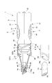
本実施形態に係る容器たる塗布用容器は、例えば塗布物としての接着剤Bを塗布するためのものであり、接着剤を収容する容器本体1と容器本体1の先端を封止するためのキャップ7とを有している。この容器本体1は、収容部2に取付けられた押圧ボタン3を指などで押圧することにより収容部2内に収容された密閉部たるチューブTに充填された接着剤Bが塗布部たるノズル6へと押し出され、当該ノズル6の先端面68から接着剤Bを対象物へ塗布し得るものである。この塗布用容器は、使用しない状態では図3に示すように、キャップ7によりノズル6の先端が密閉されることにより、接着剤Bが外気に触れることを回避した状態となるものである。このキャップ7の構成についての具体的な記載は中キャップ5等とともに後に詳述する。
The container for application which is a container according to the present embodiment is for applying, for example, an adhesive B as an application, and includes a container body 1 for storing the adhesive and a cap for sealing the tip of the container body 1. 7. The container body 1 includes a nozzle 6 serving as an application portion of an adhesive B filled in a tube T serving as a sealed portion housed in the housing portion 2 by pressing a push button 3 attached to the housing portion 2 with a finger or the like. The adhesive B can be applied to the object from the tip surface 68 of the nozzle 6. When the coating container is not in use, as shown in FIG. 3, the tip of the nozzle 6 is sealed by the cap 7, thereby preventing the adhesive B from touching the outside air. The specific description of the configuration of the cap 7 will be described later together with the middle cap 5 and the like.
またチューブTは、例えば薄板状に成形されたアルミ板が接着剤Bを密閉保持した状態で成形されたチューブ本体T1と、チューブ本体T1の一端側で雄ねじ状に成形された取付ねじ部T2と、取付ねじ部T2のさらに一端側においてアルミ素材を薄く構成することにより、取付ねじ部T2に囲まれた内側でアルミ素材が破られた状態で接着剤Bを外部へ抽出させ得る抽出面T3とを有している。当該チューブTの構成としては、例えば既存の接着剤Bや液状またはゲル状の薬品等を保持するために考案された既存のものである。すなわち、チューブTはそれ単体でも容器として使用され得るものである。その場合、チューブ本体T1の表面に表裏をなすよう平面状にそれぞれ形成された腹部T4が指等で押圧されることにより、抽出面T3のアルミ素材が破られた箇所から塗布物つまり接着剤BがチューブT外部へ抽出され得る。
The tube T includes, for example, a tube main body T1 formed in a state where an aluminum plate formed into a thin plate shape holds the adhesive B hermetically, and an attachment screw portion T2 formed into a male screw shape at one end of the tube main body T1. An extraction surface T3 that allows the adhesive B to be extracted to the outside in a state where the aluminum material is torn inside the mounting screw portion T2 by making the aluminum material thin at the one end side of the mounting screw portion T2. have. The configuration of the tube T is, for example, an existing one designed to hold the existing adhesive B, liquid or gel chemicals, and the like. That is, the tube T alone can be used as a container. In that case, the abdomen T4 formed in a planar shape so as to make the front and back surfaces of the tube body T1 face each other is pressed with a finger or the like, so that the applied material, that is, the adhesive B from the portion where the aluminum material of the extraction surface T3 is broken. Can be extracted outside the tube T.
そしてこの容器本体1は、図4に示すように、その構成部品として、上記の収容部2、押圧ボタン3及びノズル6の他、収容部2内に装着される内キャップ4と、ノズル6を固定した状態で収容部2に外嵌する中キャップ5とを有し、これらを適宜組み立てることによってなるものである。
As shown in FIG. 4, the container main body 1 includes an inner cap 4 and a nozzle 6 mounted in the housing portion 2 in addition to the housing portion 2, the push button 3 and the nozzle 6. It has a middle cap 5 that is externally fitted to the accommodating portion 2 in a fixed state, and is assembled by appropriately assembling them.
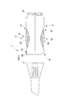
ここで、本実施形態に係るキャップ7は、容器本体1を蓋止めした状態で前記ノズル6の先端へ前記ノズル6の延出する軸線方向に沿って挿入される突出部74と、当該突出部74が立ち上がる立ち上がり箇所を前記ノズル6の延出する軸線に対し傾斜して設けた傾斜立ち上がり面75とを具備することを特徴とする。当該キャップ7の構成については後に詳述する。
Here, the cap 7 according to the present embodiment includes a protrusion 74 that is inserted along the axial direction in which the nozzle 6 extends to the tip of the nozzle 6 in a state where the container body 1 is closed, and the protrusion An inclined rising surface 75 is provided, in which a rising portion where 74 rises is inclined with respect to the axis of the nozzle 6 extending. The configuration of the cap 7 will be described in detail later.
以下、容器本体1の各部の構成並びにキャップ7の構成について順次説明する。
Hereinafter, the configuration of each part of the container body 1 and the configuration of the cap 7 will be sequentially described.
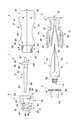
収容部2は、例えば樹脂により一体成型されたもので、ノズル6を位置付けた先端とは反対である基端側に設けられた樹脂ヒンジを介して対称に成型された、所謂半割構造をなすものである。つまり収容部2は収容する他の構成要素を樹脂ヒンジを介して挟み込む態様で保持している。この収容部2は、長手方向、幅方向共に中心に当たる位置を開口させて形成し押圧ボタン3を表出させ得るボタン穴21と、押圧ボタン3を内面側且つ基端近傍で挟持するための溝であるボタン取付部22と、内キャップ4を内面側且つ先端近傍で挟持するための溝である内キャップ取付部23と、中キャップ5を外嵌させ得る中キャップ取付部24とを有している。そしてこの中キャップ取付部24が、後述する係合案内部25と、分別廃棄の際に中キャップ5を離脱させるための離脱案内部201と、当該離脱案内部へと誘導する離脱誘導部202とを有しているものである。離脱案内部201とは、係合案内部25近傍に設けた中キャップ取付部24の長手方向に延びる溝である。離脱誘導部202とは、係合案内部25から離脱案内部201に至る表面を曲面状に加工したアール面である。
The housing portion 2 is integrally molded of resin, for example, and has a so-called halved structure that is symmetrically molded via a resin hinge provided on the base end side opposite to the tip end where the nozzle 6 is positioned. Is. That is, the accommodating part 2 is hold | maintained in the aspect which pinches | interposes the other component to accommodate via a resin hinge. The housing portion 2 is formed by opening a position corresponding to the center in both the longitudinal direction and the width direction so that the push button 3 can be exposed, and a groove for holding the push button 3 on the inner surface side and in the vicinity of the proximal end. A button mounting portion 22, an inner cap mounting portion 23 that is a groove for holding the inner cap 4 on the inner surface side and in the vicinity of the tip, and a middle cap mounting portion 24 to which the middle cap 5 can be fitted. Yes. The middle cap mounting portion 24 includes an engagement guide portion 25 to be described later, a separation guide portion 201 for separating the middle cap 5 at the time of sorting and discarding, and a separation guide portion 202 for guiding the separation guide portion to the separation guide portion. It is what has. The disengagement guide portion 201 is a groove extending in the longitudinal direction of the middle cap attachment portion 24 provided in the vicinity of the engagement guide portion 25. The disengagement guiding portion 202 is a rounded surface obtained by processing the surface from the engagement guide portion 25 to the disengagement guide portion 201 into a curved surface.
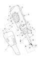
押圧ボタン3は、例えば弾性を有する樹脂によって一体成形された対称形状をなすもので、使用者に直接押圧されるボタン本体31と、このボタン本体31に押圧されてチューブ本体T1の、詳細には平面状をなす腹部T4を一方の面、他方の面からともに均一な強さで押圧することができる押圧板32と、これら対をなすボタン本体31と押圧板32とを樹脂の弾性により動作可能に保持し、収容部2の基端側で表出する基端部33とを有している。ボタン本体31は、具体的に説明すると、指等が滑らず摘みやすいように複数のリブを等間隔に配置する凹凸形状に形成された操作部34と、操作部34の基端側において湾曲した薄肉状のヒンジ部36とを有している。押圧板32は、先端部分近傍から相反する方向に突出し、突出した端部でボタン本体31に当接し得る伝達リブ35と、基端部においてチューブTの他端を挟持するとともに薄肉である故に優先的に湾曲し得る挟持ヒンジ37とを有している。
The press button 3 has a symmetrical shape integrally formed of, for example, an elastic resin. The button main body 31 that is directly pressed by the user and the tube main body T1 that is pressed by the button main body 31 in detail. The pressing plate 32 that can press the flat abdomen T4 from one side and the other side with uniform strength, and the paired button body 31 and pressing plate 32 can be operated by the elasticity of the resin. And a base end portion 33 that is exposed on the base end side of the housing portion 2. More specifically, the button main body 31 is curved at the proximal end side of the operation portion 34 and the operation portion 34 formed in an uneven shape in which a plurality of ribs are arranged at equal intervals so that a finger or the like can be easily picked without slipping. And a thin hinge 36. The pressing plate 32 protrudes in the opposite direction from the vicinity of the distal end portion, and the transmission rib 35 that can come into contact with the button main body 31 at the protruding end portion and the other end of the tube T at the proximal end portion are sandwiched and are preferential because they are thin. And a sandwiching hinge 37 that can be curved.
しかして本実施形態に係る押圧ボタン3は、図5乃至図7に示すように、チューブTを収容した収容部2に取付けた対をなすボタン本体31と、このボタン本体31を押圧することにより押圧されるとともにチューブTの腹部T4に密着して挟み込んでなる対をなす押圧板32とを有している。そしてこの押圧板32がが、チューブTの腹部T4を抽出面T3の反対側である他端部側から抽出面T3側である一端部側へ向けて面状に押圧してなる。これにより、図6に示すように使用者が操作部34を点状に押圧してもチューブTは他端側から抽出面T3を設けた一端側へ向けて面状に順次押圧されていく。これにより、チューブT内の内容物である接着剤Bは無駄なく安定して抽出されていく。特に本実施形態では、押圧する動作において押圧板32に設けた伝達リブ35とボタン本体31との接触位置が他端側から一端側へ僅かながら変化している。これにより、図7に示すような接着剤Bの残り量が少ないチューブに対しても確実に面状に押圧し接着剤を抽出することができる。
Thus, the push button 3 according to the present embodiment, as shown in FIG. 5 to FIG. 7, forms a pair of button main bodies 31 attached to the accommodating portion 2 that accommodates the tube T, and presses the button main body 31. It has a pressing plate 32 that forms a pair that is pressed and is in close contact with the abdomen T4 of the tube T. The pressing plate 32 presses the abdomen T4 of the tube T in a planar shape from the other end side, which is the opposite side of the extraction surface T3, to the one end side, which is the extraction surface T3 side. Thereby, as shown in FIG. 6, even if the user presses the operating portion 34 in a dot shape, the tube T is sequentially pressed in a planar shape from the other end side toward one end side where the extraction surface T3 is provided. Thereby, the adhesive B which is the contents in the tube T is stably extracted without waste. In particular, in the present embodiment, the contact position between the transmission rib 35 provided on the pressing plate 32 and the button main body 31 during the pressing operation slightly changes from the other end side to the one end side. Thereby, even if it is a tube with few remaining amount of adhesives B as shown in FIG.
内キャップ4は、チューブTを収容部2の内部に固定するためのものであり、チューブTの取付ねじ部T2にねじ止めする雌ねじ部41と、収容部2の内キャップ取付部23に挿入される被取付フランジ42と、ノズル6に当接してノズル6の長手方向の位置決めをなすノズル当接部43とを有している。なお本実施形態では、内キャップ4のチューブTに対するねじ止めを円滑に行わせるよう、被取付フランジ42の外周面に凹凸を形成している。またこの外周面の凹凸が、内キャップ取付部23に収容された際に内キャップ取付部23の内面に設けられた図示しない突起に係り合い、装着時の相対回転を禁止している。
The inner cap 4 is for fixing the tube T inside the housing portion 2, and is inserted into the female screw portion 41 screwed to the mounting screw portion T 2 of the tube T and the inner cap mounting portion 23 of the housing portion 2. And a nozzle contact portion 43 that contacts the nozzle 6 and positions the nozzle 6 in the longitudinal direction. In the present embodiment, irregularities are formed on the outer peripheral surface of the mounting flange 42 so that the inner cap 4 can be smoothly screwed to the tube T. Further, the unevenness of the outer peripheral surface is engaged with a projection (not shown) provided on the inner surface of the inner cap mounting portion 23 when accommodated in the inner cap mounting portion 23, and prohibits relative rotation during mounting.
中キャップ5は、先端部に液だれ防止部50を設けてノズル6からこぼれた接着剤Bが落下してしまう不具合を有効に回避し得るものである。そしてこの中キャップ5は、表面の一部に凹凸状のローレット5a(図11)を形成するとともに、収容部2の内キャップ取付部23を外側から覆い得る外嵌部51と、表面に後述する第一ねじ溝81及び第二ねじ溝82を形成することによりキャップ7に螺着されるねじ部8と、ノズル6を軸方向に固定するための位置決め溝57を有するノズル取付部53と、外嵌部51の一部を開口させた開口部(図示せず)とを有している。外嵌部51は、本実施形態では内側へ向けて中キャップ取付部24に対し係合し得る回転係合爪55を有している。この回転係合爪55は、樹脂素材を適宜切り欠くことによって円周方向に延出させた延出部58と、延出部58の先端において内側に突出させ、中キャップ取付部24に対して直接係り合わせるための係合端59とを有している。ねじ部8の具体的な構成については後に詳述する。
The middle cap 5 is provided with a liquid dripping prevention part 50 at the tip, and can effectively avoid the problem that the adhesive B spilled from the nozzle 6 falls. The inner cap 5 forms an uneven knurl 5a (FIG. 11) on a part of the surface, and an outer fitting portion 51 that can cover the inner cap mounting portion 23 of the housing portion 2 from the outside, and a surface described later. By forming the first screw groove 81 and the second screw groove 82, the screw portion 8 screwed into the cap 7, the nozzle mounting portion 53 having the positioning groove 57 for fixing the nozzle 6 in the axial direction, And an opening (not shown) in which a part of the fitting portion 51 is opened. In the present embodiment, the outer fitting portion 51 has a rotation engagement claw 55 that can be engaged with the middle cap mounting portion 24 inward. The rotation engaging claw 55 is extended in the circumferential direction by appropriately cutting out the resin material, and protrudes inward at the tip of the extending portion 58, with respect to the middle cap mounting portion 24. And an engagement end 59 for direct engagement. A specific configuration of the screw portion 8 will be described in detail later.
ノズル6は、図8に示すように、内部の接着剤Bの有無がわかり易い様に透明又は半透明の樹脂によって一体成形されたものである。ノズル6は、収容部2から表出するノズル本体61と、中キャップ5に対して取付けられる被取付部62と、この被取付部62よりも基端側で接着剤Bを抽出する抽出管63とを有している。ノズル本体61は、先端側を傾斜方向に切り欠くことにより先端面68を形成する傾斜先端部64と、傾斜先端部64に至るまでに漸次外径が小さくなるよう形成したテーパ部69とを有している。被取付部62は中キャップ5に長手方向に位置決めされるフランジ65と、軸心廻りの回転を禁止するとともに中キャップ5に対する相対角度を決定するために突出した大小2つの位置決めリブ66a、66bとを有している。ここで、ノズル6の傾斜先端部64は、ノズル本体61を斜め方向に切断して先端面68を形成している。斯かる先端面68はノズル本体61に斜め平面状である切り口を呈している。これによりノズル6は、対象物に対する向きを異ならせることで対象物に対する接触面積を異ならせ得る先端形状をなす。これにより、接着剤Bの塗布幅を任意に変更し得る。つまりノズル6は方向性を有した形状をなす。また本実施形態では、傾斜先端部64を構成する素材の厚みを、0.3mm以下に設定することで、傾斜先端部64から塗布される接着剤Bの量をごく微量なものとして、所望の微細な箇所への接着剤Bの塗布を正確に実現し得るものとしている。すなわち、このノズル6は塗布幅を変更し得るのみならず、先端面68を上方に向けた状態では所望の箇所への点状の塗布をも可能となっている。
As shown in FIG. 8, the nozzle 6 is integrally formed of a transparent or translucent resin so that the presence or absence of the internal adhesive B can be easily understood. The nozzle 6 includes a nozzle main body 61 that is exposed from the housing portion 2, a mounted portion 62 that is attached to the middle cap 5, and an extraction pipe 63 that extracts the adhesive B on the proximal side of the mounted portion 62. And have. The nozzle body 61 has an inclined tip portion 64 that forms a tip surface 68 by notching the tip end side in an inclined direction, and a tapered portion 69 formed so that the outer diameter gradually decreases until reaching the inclined tip portion 64. is doing. The mounted portion 62 includes a flange 65 positioned in the longitudinal direction of the middle cap 5, two large and small positioning ribs 66 a and 66 b that prohibit rotation around the axis and determine a relative angle with respect to the middle cap 5. have. Here, the inclined tip portion 64 of the nozzle 6 forms a tip surface 68 by cutting the nozzle body 61 in an oblique direction. Such a front end surface 68 presents an obliquely flat cut surface in the nozzle body 61. Thereby, the nozzle 6 makes the front-end | tip shape which can vary the contact area with respect to a target object by changing the direction with respect to a target object. Thereby, the application | coating width | variety of the adhesive agent B can be changed arbitrarily. That is, the nozzle 6 has a directional shape. Moreover, in this embodiment, the thickness of the material which comprises the inclination front-end | tip part 64 is set to 0.3 mm or less, and the amount of the adhesive agent B apply | coated from the inclination front-end | tip part 64 can be made into a very trace amount, and desired It is assumed that the adhesive B can be accurately applied to a minute portion. That is, the nozzle 6 not only can change the application width, but can also apply dot-like application to a desired location when the front end surface 68 is directed upward.
本実施形態に係る容器本体1は、特に図9に示すように、前記ノズル6及び中キャップ5が前記接着剤Bを塗布し得ない状態で前記収容部2及び前記ノズル6とを係合させる第一の係合位置(P)と、当該第一の係合位置(P)から前記収容部2及び前記ノズル6が互いに所定の方向性をなした前記ノズル6が前記接着剤Bを塗布し得る状態で相対移動不能に係合させる第二の係合位置(Q)とで前記収容部2及び前記ノズル6を係合させ得るとともに前記第一の係合位置(P)から前記第二の係合位置(Q)への動作を案内し得る係合案内部25と、収容部2からノズル6及び中キャップ5を離脱させ得る離脱案内部201と、前記第二の係合位置(Q)からこの離脱案内部201までの動作を誘導する離脱誘導部202とを具備してなる。
As shown in FIG. 9 in particular, the container body 1 according to the present embodiment engages the accommodating portion 2 and the nozzle 6 with the nozzle 6 and the inner cap 5 being unable to apply the adhesive B. The first engaging position (P) and the nozzle 6 in which the accommodating portion 2 and the nozzle 6 have a predetermined direction from the first engaging position (P) apply the adhesive B. The housing portion 2 and the nozzle 6 can be engaged with each other at a second engagement position (Q) to be engaged so as not to be relatively movable in the obtained state, and the second engagement position (P) can be engaged with the second from the first engagement position (P). An engagement guide portion 25 that can guide the operation to the engagement position (Q), a disengagement guide portion 201 that can disengage the nozzle 6 and the middle cap 5 from the storage portion 2, and the second engagement position (Q). And a detachment guide part 202 for guiding the operation from the detachment guide part 201 to the detachment guide part 201. .
本実施形態では係合案内部25を、収容部2の中キャップ取付部24に設けるとともに、この係合案内部25は、ノズル6を回転不能に取付得るノズル取付部53を有した中キャップ5に設けた回転係合爪55に対し係合及び案内することにより、ノズル6を第一の係合位置(P)及び第二の係合位置(Q)へと間接的に位置決めしている。この係合案内部25は、特に図9に示すように、係合端59を挿入させるための導入案内溝26と、第一の係合位置(P)にノズル6を間接的に位置決めする第一係合穴27と、この第一係合穴27からねじ送り方向に連続する溝である回転案内溝28と、この回転案内溝28に案内されて係合端59を移動不能に位置決めすることによりノズル6を第二の係合位置(Q)に間接的に固定する第二係合穴29とを有している。
In the present embodiment, the engagement guide portion 25 is provided in the middle cap attachment portion 24 of the housing portion 2, and the engagement guide portion 25 has a nozzle attachment portion 53 that can attach the nozzle 6 in a non-rotatable manner. The nozzle 6 is indirectly positioned to the first engagement position (P) and the second engagement position (Q) by engaging and guiding the rotary engagement claw 55 provided on the nozzle. As shown in FIG. 9 in particular, the engagement guide portion 25 includes an introduction guide groove 26 for inserting the engagement end 59 and a first position for indirectly positioning the nozzle 6 at the first engagement position (P). One engagement hole 27, a rotation guide groove 28 which is a groove continuous in the screw feed direction from the first engagement hole 27, and the engagement end 59 is positioned so as to be immovable while being guided by the rotation guide groove 28. And the second engagement hole 29 for indirectly fixing the nozzle 6 to the second engagement position (Q).
続いて図10乃至図14を参照しつつ、ノズル6を第一の係合位置(P)から第二の係合位置(Q)へ案内することにより、ノズル6の向きを使用に際し好適な位置へ位置決めしつつ容器本体1を使用可能な状態とする一連の動作と、例えばチューブTの分別廃棄のために収容部2からノズル6を中キャップ5もろとも取り外す動作とについて説明する。
Next, referring to FIGS. 10 to 14, the nozzle 6 is guided from the first engagement position (P) to the second engagement position (Q), so that the orientation of the nozzle 6 is suitable for use. A series of operations for setting the container body 1 to be usable while positioning the tube 6 and an operation for removing the nozzle 6 from the container 2 together with the middle cap 5 for separating and discarding the tube T will be described.
まず図10では、ノズル6を固定した中キャップ5を収容部2へ向けて導入する際の態様を示している。実際には斯かる動作において中キャップ5はキャップ7内に装着された状態で行われる。具体的に説明すると、中キャップ5における回転係合爪55の係合端59を、導入案内溝26に挿入し得る位置に合わせる。そしてこの状態からさらに係合端59を導入案内溝26に沿って基端側へ動作させると、第一係合穴27へと係合端59が嵌り、第一の係合位置(P)をとる。この第一の係合位置(P)では、ノズル6の基端すなわち抽出管63の貫通端67はチューブTの抽出面T3から離間しているため、接着剤Bをノズル6内へ注入させ得ない状態となっている。そして、係合端59を回転案内溝28に沿って回転させるように中キャップ5をねじ送り動作させると貫通端67が回転しながら抽出面T3を貫通しチューブT内部へ挿入される。そして本実施形態では第一の係合位置(P)から90°回転する様ねじ送り動作を行ったところで、図11の通り第二係合穴29に係合端59が挿入される。この状態では係合端59は第二係合穴29に深く嵌ることにより、通常の操作力を大きく上回る外力によらなければ当該係り合いは解除され得なくなっている。また上述の通りここまでの一連の動作はキャップ7を介して行われる。それ故に係合端59が第2係合穴29に嵌った状態ではキャップの位置決め部70は収容部のキャップ止め部20に当接してそれ以上の回転が禁止される。そして同図の状態ではノズル6は位置決めリブ66が位置決め溝57に嵌り回転動作が禁止されている上、フランジ65がノズル当接部43に当接してノズル6の延出方向の動作も禁止されることにより、ノズル6は収容部2に対し、間接的に第二の係合位置(Q)で固定された状態となっている。
First, FIG. 10 shows a mode in which the middle cap 5 to which the nozzle 6 is fixed is introduced toward the housing portion 2. Actually, the middle cap 5 is mounted in the cap 7 in such an operation. More specifically, the engagement end 59 of the rotation engagement claw 55 in the middle cap 5 is aligned with a position where it can be inserted into the introduction guide groove 26. When the engagement end 59 is further moved to the base end side along the introduction guide groove 26 from this state, the engagement end 59 is fitted into the first engagement hole 27 and the first engagement position (P) is set. Take. In this first engagement position (P), the base end of the nozzle 6, that is, the through end 67 of the extraction pipe 63 is separated from the extraction surface T3 of the tube T, so that the adhesive B can be injected into the nozzle 6. There is no state. Then, when the middle cap 5 is screw-fed so as to rotate the engagement end 59 along the rotation guide groove 28, the penetration end 67 passes through the extraction surface T3 and is inserted into the tube T while rotating. In this embodiment, when the screw feeding operation is performed so as to rotate 90 ° from the first engagement position (P), the engagement end 59 is inserted into the second engagement hole 29 as shown in FIG. In this state, the engagement end 59 is fitted deeply into the second engagement hole 29, so that the engagement cannot be released unless the external force greatly exceeds the normal operation force. As described above, a series of operations up to here are performed through the cap 7. Therefore, in a state where the engagement end 59 is fitted in the second engagement hole 29, the cap positioning portion 70 abuts against the cap stopper 20 of the housing portion, and further rotation is prohibited. In the state shown in the figure, the positioning rib 66 of the nozzle 6 is fitted in the positioning groove 57 and the rotation operation is prohibited, and the flange 65 contacts the nozzle contact portion 43 and the operation in the extending direction of the nozzle 6 is also prohibited. As a result, the nozzle 6 is indirectly fixed to the accommodating portion 2 at the second engagement position (Q).
第二の係合位置(Q)では、ノズル6の先端面68は収容部2に取付けられた押圧ボタン3のボタン本体31が表出する向きと同じ向きを向いた状態となっている。すなわち操作部34が表出する向きと、ノズル6の先端面68が臨む向きとが一致する。よって、チューブ本体T1の腹部T4及び操作部34が表出する向きと、ノズル6の先端面68が臨む向きとが一致することになる。つまり、チューブTの押圧操作と先端面68からの接着剤Bの吐出の視認とが容易となる。これにより、使用者はボタン本体31を押圧する向きから先端面68の向きを容易に認識し得る。
In the second engagement position (Q), the tip surface 68 of the nozzle 6 is in the same direction as the direction in which the button main body 31 of the push button 3 attached to the accommodating portion 2 is exposed. That is, the direction in which the operation unit 34 is exposed matches the direction in which the tip surface 68 of the nozzle 6 faces. Therefore, the direction in which the abdomen T4 and the operation unit 34 of the tube body T1 are exposed matches the direction in which the tip surface 68 of the nozzle 6 faces. That is, the pressing operation of the tube T and the visual recognition of the discharge of the adhesive B from the distal end surface 68 are facilitated. Thereby, the user can easily recognize the direction of the distal end surface 68 from the direction in which the button body 31 is pressed.
しかして本実施形態では、中キャップ5が収容部2から離脱し得る離脱構造を採用している。すなわち、この第二の係合位置(Q)からさらに中キャップ5を回転させることによって、中キャップ5を収容部2から取り外すことが可能である。斯かる作業はキャップ7を用いず、中キャップ5に設けられたローレット5aを指で摘む等して行われる。なお、このような離脱構造は、中キャップ5の収容部2からの離脱に限られず、他への応用が可能である。
However, in the present embodiment, a detachment structure in which the middle cap 5 can be detached from the accommodating portion 2 is adopted. That is, the middle cap 5 can be removed from the housing portion 2 by further rotating the middle cap 5 from the second engagement position (Q). Such an operation is performed without using the cap 7, such as picking the knurl 5 a provided on the middle cap 5 with a finger. Such a detachment structure is not limited to the detachment of the middle cap 5 from the housing portion 2, and can be applied to other applications.
すなわち本実施形態では、係合位置たる第二の係合位置(Q)からさらに離脱要素である中キャップ5を動作させることにより当該中キャップ5を離脱し得るように形成した、被離脱要素たる収容部2に形成した離脱案内部201と、係合位置からこの離脱案内部201へと誘導する離脱誘導部202とを有している。具体的に説明すると、図11及び図12に示した第二の係合位置(Q)から、中キャップ5表面に設けたローレット5aを摘む等してさらに回転させると図13に示した状態となる。この状態では、係合端59は第二の係合穴29から脱出し、離脱誘導部202に誘導されることにより中キャップ取付部24の上端まで延びる溝状の離脱案内部201へと略接した離脱可能位置をとる。
In other words, in the present embodiment, it is a to-be-removed element formed so that the middle cap 5 that is the disengaging element can be further disengaged from the second engaging position (Q) that is the engaging position by operating the middle cap 5. A separation guide portion 201 formed in the housing portion 2 and a separation guide portion 202 for guiding the engagement guide portion 201 to the separation guide portion 201 are provided. More specifically, when the knurling 5a provided on the surface of the middle cap 5 is picked and rotated further from the second engagement position (Q) shown in FIGS. 11 and 12, the state shown in FIG. Become. In this state, the engagement end 59 comes out of the second engagement hole 29 and is guided to the separation guide portion 202 so as to substantially contact the groove-shaped separation guide portion 201 extending to the upper end of the middle cap mounting portion 24. Take the position that can be removed.
そして係合端59を溝形状をなす離脱案内部201に接した状態から中キャップ5を引っ張ると、図14に示すように、小さい力で中キャップ5を収容部2から離脱させることができる。そして中キャップ5を取り外した収容部2から使い切ったチューブTを取り出す。つまりアルミ製のチューブTは樹脂からなる他の部品とは別に廃棄することができる。以上に説明した、離脱要素たる中キャップ5及び被離脱要素たる収容部2による離脱構造は、他の種々の組立製品の構造として採用することができる。
Then, when the middle cap 5 is pulled from a state where the engaging end 59 is in contact with the separation guide portion 201 having a groove shape, the middle cap 5 can be detached from the housing portion 2 with a small force as shown in FIG. And the used tube T is taken out from the accommodating part 2 which removed the middle cap 5. FIG. That is, the aluminum tube T can be discarded separately from other parts made of resin. The above-described detachment structure with the middle cap 5 as the detachable element and the accommodating portion 2 as the detachable element can be adopted as the structure of other various assembled products.
ねじ部8は、中キャップ5表面に設けられた単一のねじ溝である第一ねじ溝81と、この第一ねじ溝81よりも深く、幅寸法も大きく形成された第二ねじ溝82と、中キャップ5の表面において、第一ねじ溝81の始端部分を含む、第二ねじ溝の始端部分以外の部分に設けられた段部83と、第二ねじ溝82の終端付近に設けた段差である乗り越え部84とを有している。第二ねじ溝82は、第一ねじ溝に対して角度位相を180°異ならせた位置に形成された単一の溝であり、終端付近に乗り越え部84を設けることで、この乗り越え部84をキャップ7の第二凸部(図示せず)が超えたときに使用者にクリック感を与え、当該第二凸部が動作終端付近にさしかかったことを知らしめるようになっている。段部83は、第一ねじ溝81の始端部分において外径を第一ねじ溝81と第二ねじ溝82との深さ寸法の差だけ径が大きくなるように形成した箇所である。この段部83に第二凸部が当接することで、キャップ7のねじ部8に対する螺合が禁止される。
The screw portion 8 includes a first screw groove 81 that is a single screw groove provided on the surface of the middle cap 5, and a second screw groove 82 that is deeper than the first screw groove 81 and has a larger width dimension. In the surface of the middle cap 5, a step portion 83 provided at a portion other than the start end portion of the second screw groove including the start end portion of the first screw groove 81, and a step provided near the end of the second screw groove 82. And an overpass portion 84 which is The second screw groove 82 is a single groove formed at a position where the angular phase is 180 ° different from that of the first screw groove. By providing the ride-over portion 84 near the end, the ride-over portion 84 is When the second convex portion (not shown) of the cap 7 is exceeded, a click feeling is given to the user to let the user know that the second convex portion is approaching the end of the operation. The step portion 83 is a portion formed so that the outer diameter of the first end portion of the first screw groove 81 is increased by the difference in depth between the first screw groove 81 and the second screw groove 82. When the second convex portion comes into contact with the step portion 83, screwing of the cap 7 to the screw portion 8 is prohibited.
一方キャップ7は、図15乃至図17に示すように、ノズル6を覆い得るように容器本体1の先端側を覆うべく螺着するものである。このキャップ7は例えば樹脂の一体成形によってなるものであり、内面側に樹脂を突出させて形成した第一凸部71及び第二凸部(図示せず)と、基端側縁部において縁部に段差状に形成された位置決め部70と、キャップ7内部の先端付近において長手方向に延びノズル6の外面に摺接し得る例えば4本の摺接リブ73と、キャップ7の先端部内面から基端側へ向けて円筒状に突出しノズル6内部に挿入され得る突出部74と、突出部74の立ち上がる底面である傾斜立ち上がり面75とを有している。
On the other hand, as shown in FIGS. 15 to 17, the cap 7 is screwed so as to cover the front end side of the container body 1 so as to cover the nozzle 6. The cap 7 is formed, for example, by integral molding of a resin, and includes a first convex portion 71 and a second convex portion (not shown) formed by protruding the resin on the inner surface side, and an edge portion at the base end side edge portion. A positioning portion 70 formed in a step shape, four sliding contact ribs 73 extending in the longitudinal direction in the vicinity of the distal end inside the cap 7 and capable of slidingly contacting the outer surface of the nozzle 6, and the proximal end from the inner surface of the distal end portion of the cap 7. It has a protruding portion 74 that protrudes in a cylindrical shape toward the side and can be inserted into the nozzle 6, and an inclined rising surface 75 that is a bottom surface on which the protruding portion 74 rises.
第一凸部71は、上記の第一ねじ溝81が形成される深さ寸法及び幅寸法に対応させた概略矩形状に突出させた突起である。第二凸部(図示せず)は、上記第一凸部71に対面する位置に形成され、上記の第二ねじ溝82が形成された深さ寸法及び幅寸法に対応する寸法、すなわち第一凸部71よりも大きい突出寸法及び突出面積を有する矩形状に突出することで、第二ねじ溝82に対しがたつき無く挿入され得るものである。位置決め部70は、終了位置(Q1)で容器本体1側に当接することにより、当該終了位置(Q1)を有効に保持し得るものである。この位置決め部70は容器本体1における中キャップ7ではなく収容部に設けたキャップ7止め部に対して当接する。これにより使用者が強い力でキャップ7を締めようと螺合させてもその作用力が中キャップ5に影響する事がない。摺接リブ73は、キャップ7内部の周方向において等間隔に4箇所設けられたリブであり、先端をノズル6のテーパ部の角度に応じて傾斜させて形成することで、終了位置(Q1)に至るまでの螺合時にテーパ部に摺接し、テーパ部に付着した接着剤Bを掻き取る役目を果たすものである。突出部74は、終了位置(Q1)において傾斜先端部に隙間無く栓をするように挿入されることで、終了位置(Q1)でノズル6内の接着剤Bが外気に触れて固着してしまうことを回避するためのものである。そしてこの突出部74は、キャップ7内部の先端部分から螺合進退方向つまり軸線の方向に対し傾斜方向に面するように形成した傾斜端74aを有している。この傾斜端74aにより、突出部74はノズル6の傾斜先端部64の形状に干渉し難い構成となっている。
The 1st convex part 71 is the processus | protrusion protruded in the substantially rectangular shape corresponding to the depth dimension and width dimension in which said 1st thread groove 81 is formed. A second convex part (not shown) is formed at a position facing the first convex part 71, and corresponds to the depth dimension and the width dimension in which the second screw groove 82 is formed, that is, the first convex part. By projecting into a rectangular shape having a larger projecting dimension and projecting area than the convex portion 71, the second screw groove 82 can be inserted without rattling. The positioning unit 70 can effectively hold the end position (Q1) by contacting the container body 1 side at the end position (Q1). The positioning portion 70 abuts against the cap 7 stopper provided in the housing portion, not the middle cap 7 in the container body 1. As a result, even if the user screws the cap 7 with a strong force, the acting force does not affect the middle cap 5. The sliding contact ribs 73 are provided at four equal intervals in the circumferential direction inside the cap 7, and the end positions (Q 1) are formed by inclining the tips according to the angle of the taper portion of the nozzle 6. It is slidably contacted with the taper part at the time of screwing up to, and plays the role of scraping off the adhesive B adhering to the taper part. The protrusion 74 is inserted so as to plug the inclined tip portion without a gap at the end position (Q1), so that the adhesive B in the nozzle 6 comes into contact with the outside air and is fixed at the end position (Q1). This is to avoid this. The projecting portion 74 has an inclined end 74a formed so as to face the forward / backward direction of the screwing, that is, the direction of the axis from the tip portion inside the cap 7 in an inclined direction. Due to the inclined end 74 a, the projecting portion 74 is configured not to interfere with the shape of the inclined tip end portion 64 of the nozzle 6.
そして本実施形態では、図15~図17に示すように、使用者がキャップ7をどのような向きから回転させても、必ず単一の相対位置にある開始位置(P1)から螺合が始まり、同じく単一の終了位置(Q1)で螺合が終了するようになっている。
In this embodiment, as shown in FIGS. 15 to 17, screwing always starts from a start position (P1) that is at a single relative position, regardless of the direction in which the user rotates the cap 7. Similarly, screwing ends at a single end position (Q1).
先ず、使用者がキャップ7を締めるべく任意の向きをなすキャップ7でノズル6を覆い、ねじ送り操作を開始する場合、第二凸部は段部83に阻まれた状態で回転する。勿論この段部83は第一ねじ溝81の始端にも形成されているため、第二凸部が誤って第一ねじ溝81に挿入されることは無い。そして第一凸部71、第二凸部が第一ねじ溝、第二ねじ溝82の内に入ったときが図15に示す開始位置(P1)であり、ここから螺合が開始される。このときには突出部74は傾斜端を74aを図示手前に向けた状態であり、まだ傾斜先端部64に接していない。そしてキャップ7の回転を続けると、図16に示すように第一凸部71、第二凸部がそれぞれ第一ねじ溝81、第二ねじ溝82内を進んでゆく。同図に示すように開始位置(P1)から90°キャップをねじ込んだ状態では斜め上方を向いたノズル6の先端面68と、斜め下方を向いた突出部74の傾斜端74aとがそれぞれ向かい合い且つ僅かながら接した状態となっており、ここから傾斜端74aの傾斜先端部64への挿入が始まる。ここで傾斜先端部64は素材の厚みを0.3mmという薄肉に設定しているため図示の状態から若干のゆがみ、曲がりが生じている場合があるが、突出部74が挿入されることで当該曲がり等を矯正されていくことになる。そして第一凸部71、第二凸部が第一ねじ溝81、第二ねじ溝82内を進み、開始位置(P1)から180°回転したとき、キャップ7は図17に示す終了位置(Q1)で位置決めされる。ここで当該キャップ7は終了位置(Q1)において第一凸部71、第二凸部が第一ねじ溝81、第二ねじ溝82の終端に当接するのではない。つまり第一凸部71及び第二凸部とは別の箇所に設けた位置決め部70がねじ部8ではなく、容器本体1の収容部側に設けたキャップ止め部20に当接する。これにより、使用者が強い操作力でキャップ7を操作したとしても当該操作力がねじ部8、ひいては中キャップ7に影響することを有効に回避している。またこのとき、先端面68はちょうど傾斜立ち上がり面75に密着するかごく近接した状態となるとともに、傾斜端74aの向き図示で奥方に面した状態、すなわち先端面68の向きとは90°位相が異なった状態となっている。これにより、突出部74と傾斜先端部64との接触面積を小さくし、キャップ7を開ける際の接着剤Bによる突出部74への影響を最小限に抑えている。
First, when the user covers the nozzle 6 with the cap 7 in an arbitrary direction so as to tighten the cap 7 and starts the screw feeding operation, the second convex portion rotates while being blocked by the step portion 83. Of course, since the step portion 83 is also formed at the starting end of the first screw groove 81, the second convex portion is not erroneously inserted into the first screw groove 81. And when the 1st convex part 71 and the 2nd convex part enter in the 1st thread groove and the 2nd thread groove 82, it is the starting position (P1) shown in FIG. 15, and screwing is started from here. At this time, the protrusion 74 is in a state in which the inclined end 74a faces the front of the drawing, and has not yet contacted the inclined tip 64. As the cap 7 continues to rotate, the first convex portion 71 and the second convex portion proceed through the first screw groove 81 and the second screw groove 82, respectively, as shown in FIG. As shown in the figure, when the 90 ° cap is screwed from the start position (P1), the tip surface 68 of the nozzle 6 facing diagonally upward and the inclined end 74a of the projecting portion 74 facing diagonally downward face each other, and The contact is slightly made, and the insertion of the inclined end 74a into the inclined tip portion 64 starts from here. Here, since the inclined tip portion 64 is set to have a thin material thickness of 0.3 mm, there may be some distortion and bending from the state shown in the figure, but the protrusion 74 is inserted to Bending will be corrected. And when the 1st convex part 71 and the 2nd convex part advance the inside of the 1st thread groove 81 and the 2nd thread groove 82, and rotate 180 degrees from the start position (P1), the cap 7 is the end position (Q1 shown in FIG. 17). ). Here, at the end position (Q1) of the cap 7, the first convex portion 71 and the second convex portion do not contact the terminal ends of the first screw groove 81 and the second screw groove 82. That is, the positioning portion 70 provided at a location different from the first convex portion 71 and the second convex portion abuts not the screw portion 8 but the cap stopper portion 20 provided on the container portion 1 side. Thereby, even if the user operates the cap 7 with a strong operating force, it is effectively avoided that the operating force affects the screw portion 8 and thus the middle cap 7. Further, at this time, the tip surface 68 is in a state of being in close proximity to the inclined rising surface 75 and is in a state facing the back in the orientation illustration of the inclined end 74a, that is, the direction of the tip surface 68 has a 90 ° phase. It is in a different state. Thereby, the contact area of the protrusion part 74 and the inclination front-end | tip part 64 is made small, and the influence on the protrusion part 74 by the adhesive agent B at the time of opening the cap 7 is suppressed to the minimum.
以上のような構成とすることにより、本実施形態に係るキャップ7は、突出部74の立ち上がり面積は軸線方向から傾斜している、詳細には軸線方向に直交する仮想の平面から傾斜しているので突出部74自体の軸線方向に直交する角度からの断面積よりも大きな面積となる。その結果突出部74をより大きな面積で立ち上がらせることができ、特に立ち上がり箇所の強度の高いものとなっている。これにより、接着剤Bによって損傷し難く安定して容器本体1つまりノズル6の傾斜先端部64を蓋止し得るキャップ7を実現している。
With the configuration as described above, in the cap 7 according to this embodiment, the rising area of the protrusion 74 is inclined from the axial direction, specifically, from the virtual plane orthogonal to the axial direction. Therefore, the area is larger than the cross-sectional area from the angle orthogonal to the axial direction of the protrusion 74 itself. As a result, the protruding portion 74 can be raised with a larger area, and the strength of the rising portion is particularly high. Thereby, the cap 7 which can hardly be damaged by the adhesive B and can stably cover the container main body 1, that is, the inclined tip portion 64 of the nozzle 6, is realized.
本実施形態の突出部74は高い強度をもってノズル6の先端に挿入しているので、特にノズル6において薄肉に形成された傾斜先端部64の形状も有効に担保している。
Since the projecting portion 74 of this embodiment is inserted at the tip of the nozzle 6 with high strength, the shape of the inclined tip portion 64 formed thin in the nozzle 6 is effectively secured.
また本実施形態ではねじ部に設けた第一ねじ溝81、第一凸部71、第二ねじ溝82、第二凸部による螺合構造を適用することにより、ノズル6の傾斜先端部64に対する突出部74の確実な位置決めを担保している。
Further, in the present embodiment, by applying a screwed structure by the first screw groove 81, the first convex portion 71, the second screw groove 82, and the second convex portion provided in the screw portion, the inclined tip portion 64 of the nozzle 6 is applied. Secure positioning of the protrusion 74 is ensured.
特に本実施形態では突出部74の先端を傾斜端として形成することで、螺合時のノズル6への干渉を回避しながら、スムーズに傾斜先端部64に挿入させやすくしている。
Particularly in this embodiment, the tip of the protrusion 74 is formed as an inclined end, so that it can be smoothly inserted into the inclined tip 64 while avoiding interference with the nozzle 6 during screwing.
そして上述の通り突出部74を傾斜先端部64へ容易且つ確実な挿入を実現することにより、同実施形態の如く形状の担保が難しいとされる薄肉に形成された、詳細には先端の厚みが0.3mm以下に設定されている傾斜先端部64に対しても、容易且つ確実に突出部74を挿入することで当該傾斜先端部64の形状を有効に担保している。
As described above, the protrusion 74 is formed into a thin wall that is difficult to secure the shape as in the same embodiment by realizing easy and reliable insertion of the protrusion 74 into the inclined tip 64. Even with respect to the inclined tip portion 64 set to 0.3 mm or less, the shape of the inclined tip portion 64 is effectively secured by inserting the protruding portion 74 easily and reliably.
<第二実施形態>
以下、本発明の第二実施形態について図18~図40を参照して説明する。 <Second embodiment>
Hereinafter, a second embodiment of the present invention will be described with reference to FIGS.
以下、本発明の第二実施形態について図18~図40を参照して説明する。 <Second embodiment>
Hereinafter, a second embodiment of the present invention will be described with reference to FIGS.
本実施形態に係る塗布用容器は、例えば塗布物としての接着剤Bを塗布するためのものであり、接着剤を収容する容器本体1と容器本体1の先端を封止するためのキャップ7とを有している。この容器本体1は、収容部2に取付けられた押圧ボタン3を指などで押圧することにより収容部2内に収容された密閉部たるチューブTに充填された接着剤Bが塗布部たるノズル6へと押し出され、当該ノズル6の先端面68から接着剤Bを対象物へ塗布し得るものである。この塗布用容器は、使用しない状態では図20に示すように、キャップ7によりノズル6の先端が密閉されることにより、接着剤Bが外気に触れることを回避した状態となるものである。このキャップ7の構成についての具体的な記載は中キャップ5等とともに後に詳述する。
The container for application according to the present embodiment is, for example, for applying an adhesive B as an application, and includes a container body 1 that contains the adhesive and a cap 7 that seals the tip of the container body 1. have. The container body 1 includes a nozzle 6 serving as an application portion of an adhesive B filled in a tube T serving as a sealed portion housed in the housing portion 2 by pressing a push button 3 attached to the housing portion 2 with a finger or the like. The adhesive B can be applied to the object from the tip surface 68 of the nozzle 6. When the coating container is not used, the tip of the nozzle 6 is sealed by the cap 7 as shown in FIG. 20, thereby preventing the adhesive B from touching the outside air. The specific description of the configuration of the cap 7 will be described later together with the middle cap 5 and the like.
またチューブTは、例えば薄板状に成形されたアルミ板が接着剤Bを密閉保持した状態で成形されたチューブ本体T1と、チューブ本体T1の一端側で雄ねじ状に成形された取付ねじ部T2と、取付ねじ部T2のさらに一端側においてアルミ素材を薄く構成することにより、取付ねじ部T2に囲まれた内側でアルミ素材が破られた状態で接着剤Bを外部へ抽出させ得る抽出面T3とを有している。当該チューブTの構成としては、例えば既存の接着剤Bや液状またはゲル状の薬品等を保持するために考案された既存のものである。すなわち、チューブTはそれ単体でも容器として使用され得るものである。その場合、チューブ本体T1の表面に表裏をなすよう平面状にそれぞれ形成された腹部T4が指等で押圧されることにより、抽出面T3のアルミ素材が破られた箇所から塗布物つまり接着剤BがチューブT外部へ抽出され得る。
The tube T includes, for example, a tube main body T1 formed in a state where an aluminum plate formed into a thin plate shape holds the adhesive B hermetically, and an attachment screw portion T2 formed into a male screw shape at one end of the tube main body T1. An extraction surface T3 that allows the adhesive B to be extracted to the outside in a state where the aluminum material is torn inside the mounting screw portion T2 by making the aluminum material thin at the one end side of the mounting screw portion T2. have. The configuration of the tube T is, for example, an existing one designed to hold the existing adhesive B, liquid or gel chemicals, and the like. That is, the tube T alone can be used as a container. In that case, the abdomen T4 formed in a planar shape so as to make the front and back surfaces of the tube body T1 face each other is pressed with a finger or the like, so that the applied material, that is, the adhesive B from the portion where the aluminum material of the extraction surface T3 is broken. Can be extracted outside the tube T.
そしてこの容器本体1は、図21に示すように、その構成部品として、上記の収容部2、押圧ボタン3及びノズル6の他、収容部2内に装着される内キャップ4と、ノズル6を固定した状態で収容部2に外嵌する中キャップ5とを有し、これらを適宜組み立てることによってなるものである。
As shown in FIG. 21, the container body 1 includes, as its constituent parts, an inner cap 4 and a nozzle 6 mounted in the housing portion 2 in addition to the housing portion 2, the push button 3 and the nozzle 6. It has a middle cap 5 that is externally fitted to the accommodating portion 2 in a fixed state, and is assembled by appropriately assembling them.
ここで、本実施形態に係る容器本体1は、接着剤Bを収容し方向性を有する形状をなす収容部2と、当該収容部2に収容された接着剤Bを対象物に対し塗布するように前記収容部2に取付けられるものであり方向性を有する傾斜先端部64を形成したノズル6とを有する容器本体1であって、前記ノズル6が前記接着剤Bを塗布し得ない状態で前記収容部2及び前記ノズル6とを係合させる前記第一の係合位置(P)と、当該第一の係合位置(P)から前記収容部2及び前記ノズル6が互いに所定の方向性をなし且つ前記ノズル6が前記接着剤Bを塗布し得る状態で相対移動不能に係合させる第二の係合位置(Q)とで前記収容部2及び前記ノズル6を係合させ得るとともに前記第一の係合位置(P)から前記第二の係合位置(Q)への動作を案内し得る係合案内部25を具備してなることを特徴とする。
Here, the container main body 1 according to the present embodiment is configured to apply the adhesive B accommodated in the accommodating part 2 that accommodates the adhesive B and has a directionality to the object. A container body 1 having a nozzle 6 formed with an inclined tip 64 having a directivity and attached to the housing portion 2, wherein the nozzle 6 cannot apply the adhesive B. The first engaging position (P) for engaging the accommodating portion 2 and the nozzle 6, and the accommodating portion 2 and the nozzle 6 have a predetermined direction from each other from the first engaging position (P). None and the second engaging position (Q) in which the nozzle 6 can be applied with the adhesive B so that the nozzle 6 can be applied with the adhesive B, the housing portion 2 and the nozzle 6 can be engaged with each other. Movement from one engagement position (P) to the second engagement position (Q) And characterized by being provided with an engaging guide portion 25 that can guide the.
また、本実施形態に係る容器本体1とキャップ7とに適用される螺着構造Xは、被螺着体たる容器本体1に設けられた第一ねじ溝81、及び、当該第一ねじ溝に挿入され得る容器本体に対し螺合し得る螺着体たるキャップ7に設けられこれら容器本体1及びキャップ7を所定の一の相対角度をなす開始位置(P1)から相対的に回転させ所定の相対角度をなす終了位置(Q1)で螺着させるために設けられた第一凸部71を有する第一螺合部X1と、第一ねじ溝81よりも深い寸法で凹ませて容器本体1に設けた第二ねじ溝82、及び、所定の第二ねじ溝82にのみ挿入され螺合し得るとともに前記第一ねじ溝81には挿入し得ないようにキャップ7に設けた第二凸部72を有する第二螺合部X2とを具備することを特徴とする。当該螺着構造Xについては後に詳述する。
Moreover, the screwing structure X applied to the container main body 1 and the cap 7 according to the present embodiment includes the first screw groove 81 provided in the container main body 1 that is a member to be screwed, and the first screw groove. The container body 1 and the cap 7 are provided on a cap 7 that can be screwed onto a container body that can be inserted, and the container body 1 and the cap 7 are rotated relative to each other from a start position (P1) that forms a predetermined relative angle. A first threaded portion X1 having a first convex portion 71 provided for screwing at an end position (Q1) forming an angle, and a recess deeper than the first screw groove 81 are provided in the container body 1. The second screw groove 82 and the second convex portion 72 provided on the cap 7 so as to be inserted and screwed only into the predetermined second screw groove 82 and not to be inserted into the first screw groove 81 are provided. It has the 2nd screwing part X2 which has. The screw structure X will be described in detail later.
以下、容器本体1の各部の構成並びにキャップ7の構成について順次説明する。
Hereinafter, the configuration of each part of the container body 1 and the configuration of the cap 7 will be sequentially described.
収容部2は、例えば樹脂により一体成型されたもので、ノズル6を位置付けた先端とは反対である基端側に設けられた樹脂ヒンジを介して対称に成型された、所謂半割構造をなすものである。つまり収容部2は収容する他の構成要素を樹脂ヒンジを介して挟み込む態様で保持している。この収容部2は、長手方向、幅方向共に中心に当たる位置を開口させて形成し押圧ボタン3を表出させ得るボタン穴21と、押圧ボタン3を内面側且つ基端近傍で挟持するための溝であるボタン取付部22と、内キャップ4を内面側且つ先端近傍で挟持するための溝である内キャップ取付部23と、中キャップ5を外嵌させ得る中キャップ取付部24とを有している。そしてこの外キャップ取付部24が、本実施形態に係る係合案内部25を有しているものであるが、当該係合案内部25の具体的な構成については後に詳述する。
The housing portion 2 is integrally molded of resin, for example, and has a so-called halved structure that is symmetrically molded via a resin hinge provided on the base end side opposite to the tip end where the nozzle 6 is positioned. Is. That is, the accommodating part 2 is hold | maintained in the aspect which pinches | interposes the other component to accommodate via a resin hinge. The housing portion 2 is formed by opening a position corresponding to the center in both the longitudinal direction and the width direction so that the push button 3 can be exposed, and a groove for holding the push button 3 on the inner surface side and in the vicinity of the proximal end. A button mounting portion 22, an inner cap mounting portion 23 that is a groove for holding the inner cap 4 on the inner surface side and in the vicinity of the tip, and a middle cap mounting portion 24 to which the middle cap 5 can be fitted. Yes. And this outer cap attaching part 24 has the engagement guide part 25 which concerns on this embodiment, The detailed structure of the said engagement guide part 25 is explained in full detail behind.
押圧ボタン3は、例えば弾性を有する樹脂によって一体成形された対称形状をなすもので、使用者に直接押圧されるボタン本体31と、このボタン本体31に押圧されてチューブ本体T1の、詳細には平面状をなす腹部T4を一方の面、他方の面からともに均一な強さで押圧することができる押圧板32と、これら対をなすボタン本体31と押圧板32とを樹脂の弾性により動作可能に保持し、収容部2の基端側で表出する基端部33とを有している。ボタン本体31は、具体的に説明すると、指等が滑らず摘みやすいように複数のリブを等間隔に配置する凹凸形状に形成された操作部34と、操作部34の基端側から相寄る方向に突出し、突出した端部で押圧板32に当接し得る伝達リブ35とを有している。
The press button 3 has a symmetrical shape integrally formed of, for example, an elastic resin. The button main body 31 that is directly pressed by the user and the tube main body T1 that is pressed by the button main body 31 in detail. The pressing plate 32 that can press the flat abdomen T4 from one side and the other side with uniform strength, and the paired button body 31 and pressing plate 32 can be operated by the elasticity of the resin. And a base end portion 33 that is exposed on the base end side of the housing portion 2. More specifically, the button main body 31 is close to the operation portion 34 formed in a concavo-convex shape in which a plurality of ribs are arranged at equal intervals so that a finger or the like can be easily picked without slipping, and the proximal end side of the operation portion 34. It has a transmission rib 35 that protrudes in the direction and can come into contact with the pressing plate 32 at the protruding end.
内キャップ4は、チューブTを収容部2の内部に固定するためのものであり、チューブTの取付ねじ部T2にねじ止めする雌ねじ部41と、収容部2の内キャップ取付部23に挿入される被取付フランジ42と、ノズル6に当接してノズル6の長手方向の位置決めをなすノズル当接部43とを有している。なお本実施形態では、内キャップ4のチューブTに対するねじ止めを円滑に行わせるよう、被取付フランジ42の外周面に凹凸を形成している。
The inner cap 4 is for fixing the tube T inside the housing portion 2, and is inserted into the female screw portion 41 screwed to the mounting screw portion T 2 of the tube T and the inner cap mounting portion 23 of the housing portion 2. And a nozzle contact portion 43 that contacts the nozzle 6 and positions the nozzle 6 in the longitudinal direction. In the present embodiment, irregularities are formed on the outer peripheral surface of the mounting flange 42 so that the inner cap 4 can be smoothly screwed to the tube T.
中キャップ5は、先端部に液だれ防止部50を設けてノズル6からこぼれた接着剤Bが落下してしまう不具合を有効に回避し得るものである。そしてこの中キャップ5は、収容部2の内キャップ取付部23を外側から覆い得る外嵌部51と、表面にねじ面56である後述する第一ねじ溝81及び第二ねじ溝82を形成することによりキャップ7に螺着されるねじ部8と、ノズル6を軸方向に固定するための位置決め溝57を有するノズル取付部53と、外嵌部51の一部を開口させた開口部54とを有している。外嵌部51は、本実施形態では内側へ向けて中キャップ取付部24に対し係合し得る回転係合爪55を有している。この回転係合爪55は、樹脂素材を適宜切り欠くことによって円周方向に延出させた延出部58と、延出部58の先端において内側に突出させ、中キャップ取付部24に対して直接係り合わせるための係合端59とを有している。ねじ部8の具体的な構成については後に詳述する。
The middle cap 5 is provided with a liquid dripping prevention part 50 at the tip, and can effectively avoid the problem that the adhesive B spilled from the nozzle 6 falls. And this inner cap 5 forms the external fitting part 51 which can cover the inner cap attaching part 23 of the accommodating part 2 from the outer side, and the 1st thread groove 81 and the 2nd thread groove 82 which are the thread surfaces 56 which are mentioned later on the surface. Accordingly, the screw portion 8 screwed to the cap 7, the nozzle mounting portion 53 having the positioning groove 57 for fixing the nozzle 6 in the axial direction, and the opening portion 54 in which a part of the outer fitting portion 51 is opened. have. In the present embodiment, the outer fitting portion 51 has a rotation engagement claw 55 that can be engaged with the middle cap mounting portion 24 inward. The rotation engaging claw 55 is extended in the circumferential direction by appropriately cutting out the resin material, and protrudes inward at the tip of the extending portion 58, with respect to the middle cap mounting portion 24. And an engagement end 59 for direct engagement. A specific configuration of the screw portion 8 will be described in detail later.
ノズル6は、内部の接着剤Bの有無がわかり易い様に透明又は半透明の樹脂によって一体成形されたものである。ノズル6は、収容部2から表出するノズル本体61と、中キャップ5に対して取付けられる被取付部62と、この被取付部62よりも基端側で接着剤Bを抽出する抽出管63とを有している。ノズル本体61は、先端側を傾斜方向に切り欠くことにより先端面68を形成する傾斜先端部64と、傾斜先端部に至るまでに漸次外径が小さくなるよう形成したテーパ部69とを有している。被取付部62は中キャップ5に長手方向に位置決めされるフランジ65と、軸心廻りの回転を禁止するために突出した位置決めリブ66とを有している。ここで、ノズル6の傾斜先端部64は、ノズル本体61を斜め方向に切断して先端面68を形成している。斯かる先端面68はノズル本体61に斜め平面状である切り口を呈している。これによりノズル6は、対象物に対する向きを異ならせることで対象物に対する接触面積を異ならせ得る先端形状をなす。つまりノズル6は方向性を有した形状をなす。
The nozzle 6 is integrally formed of a transparent or translucent resin so that the presence or absence of the internal adhesive B can be easily understood. The nozzle 6 includes a nozzle main body 61 that is exposed from the housing portion 2, a mounted portion 62 that is attached to the middle cap 5, and an extraction pipe 63 that extracts the adhesive B on the proximal side of the mounted portion 62. And have. The nozzle body 61 has an inclined tip portion 64 that forms a tip surface 68 by notching the tip end side in the inclined direction, and a tapered portion 69 that is formed so that the outer diameter gradually decreases until reaching the inclined tip portion. ing. The mounted portion 62 has a flange 65 positioned in the longitudinal direction with respect to the middle cap 5 and a protruding positioning rib 66 for prohibiting rotation around the axis. Here, the inclined tip portion 64 of the nozzle 6 forms a tip surface 68 by cutting the nozzle body 61 in an oblique direction. Such a front end surface 68 presents an obliquely flat cut surface in the nozzle body 61. Thereby, the nozzle 6 makes the front-end | tip shape which can vary the contact area with respect to a target object by changing the direction with respect to a target object. That is, the nozzle 6 has a directional shape.
しかして本実施形態に係る容器本体1は、前記ノズル6が前記接着剤Bを塗布し得ない状態で前記収容部2及び前記ノズル6とを係合させる前記第一の係合位置(P)と、当該第一の係合位置(P)から前記収容部2及び前記ノズル6が互いに所定の方向性をなした前記ノズル6が前記接着剤Bを塗布し得る状態で相対移動不能に係合させる第二の係合位置(Q)とで前記収容部2及び前記ノズル6を係合させ得るとともに前記第一の係合位置(P)から前記第二の係合位置(Q)への動作を案内し得る係合案内部25を具備してなる。
Therefore, the container main body 1 according to the present embodiment has the first engagement position (P) in which the nozzle 6 is engaged with the housing portion 2 and the nozzle 6 in a state where the adhesive B cannot be applied. And the accommodating portion 2 and the nozzle 6 from the first engagement position (P) are engaged with each other so that the nozzle 6 can apply the adhesive B in a state in which the nozzle 6 has a predetermined direction. The accommodating portion 2 and the nozzle 6 can be engaged with each other at the second engagement position (Q), and the operation from the first engagement position (P) to the second engagement position (Q) is performed. It is provided with the engagement guide part 25 which can guide.
本実施形態では係合案内部25を、収容部2の外キャップ取付部24に設けるとともに、この係合案内部25は、ノズル6を回転不能に取付得るノズル取付部53を有した中キャップ5に設けた回転係合爪55に対し係合及び案内することにより、ノズル6を第一の係合位置(P)及び第二の係合位置(Q)へと間接的に位置決めしている。
In the present embodiment, the engagement guide portion 25 is provided in the outer cap attachment portion 24 of the housing portion 2, and the engagement guide portion 25 has the nozzle cap portion 53 that can attach the nozzle 6 in a non-rotatable manner. The nozzle 6 is indirectly positioned to the first engagement position (P) and the second engagement position (Q) by engaging and guiding the rotary engagement claw 55 provided on the nozzle.
係合案内部25は、特に図22に示すように、係合端59を挿入させるための導入案内溝26と、第一の係合位置(P)にノズル6を間接的に位置決めする第一係合穴27と、この第一係合穴27からねじ送り方向に連続する溝である回転案内溝28と、この回転案内溝28に案内されて係合端59を移動不能に位置決めすることによりノズル6を第二の係合位置(Q)に間接的に固定する第二係合穴29とを有している。
As shown in FIG. 22 in particular, the engagement guide portion 25 includes an introduction guide groove 26 for inserting the engagement end 59 and a first position for indirectly positioning the nozzle 6 at the first engagement position (P). By engaging the engagement hole 27, the rotation guide groove 28 that is a groove continuous from the first engagement hole 27 in the screw feeding direction, and the engagement end 59 is positioned so as not to move by being guided by the rotation guide groove 28. And a second engagement hole 29 for indirectly fixing the nozzle 6 to the second engagement position (Q).
ここで図23~図27を参照しつつ、ノズル6を第一の係合位置(P)から第二の係合位置(Q)へ案内することにより、ノズル6の向きを使用に際し好適な位置へ位置決めしつつ容器本体1を使用可能な状態とする一連の動作について説明する。
Here, referring to FIGS. 23 to 27, the nozzle 6 is guided from the first engagement position (P) to the second engagement position (Q) so that the orientation of the nozzle 6 is suitable for use. A series of operations for setting the container main body 1 in a usable state while positioning to the position will be described.
まず図23では、ノズル6を固定した中キャップ5を収容部2へ向けて導入する際の態様を示している。具体的には、回転係合爪55の係合端59を、導入案内溝26に挿入し得る位置に合わせる。そしてこの状態からさらに係合端59を導入案内溝26に沿って基端側へ動作させると、図25及び図27に示す第一の係合位置(P)をとる。この第一の係合位置(P)では、ノズル6の基端すなわち抽出管63の貫通端67はチューブTの抽出面T3から離間しているため、接着剤Bをノズル6内へ注入させ得ない状態となっている。
First, FIG. 23 shows a mode in which the middle cap 5 to which the nozzle 6 is fixed is introduced toward the housing portion 2. Specifically, the engagement end 59 of the rotation engagement claw 55 is adjusted to a position where it can be inserted into the introduction guide groove 26. When the engagement end 59 is further moved to the proximal end side along the introduction guide groove 26 from this state, the first engagement position (P) shown in FIGS. 25 and 27 is taken. In this first engagement position (P), the base end of the nozzle 6, that is, the through end 67 of the extraction pipe 63 is separated from the extraction surface T3 of the tube T, so that the adhesive B can be injected into the nozzle 6. There is no state.
ここで、図25に示す状態から係合端59を回転案内溝28にそって回転させるように中キャップ5をねじ送り動作させると貫通端67が回転しながら抽出面T3を貫通しチューブT内部へ挿入される。そして本実施形態では第一の係合位置(P)から90°回転する様ねじ送り動作を行ったところで、図25及び図27に示すような第二係合穴29に係合端59が挿入される。この状態では係合端59は第二係合穴29に深く嵌ることにより、通常の操作力を大きく上回る外力によらなければ当該係り合いは解除され得なくなっている。そして同図の状態ではノズル6は位置決めリブ66が位置決め溝57に嵌り回転動作が禁止されている上、フランジ65がノズル当接部43に当接してノズル6の延出方向の動作も禁止されることにより、ノズル6は収容部2に対し、間接的に第二の係合位置(Q)で固定された状態となっている。
Here, when the middle cap 5 is screw-fed so as to rotate the engagement end 59 along the rotation guide groove 28 from the state shown in FIG. 25, the penetration end 67 passes through the extraction surface T3 while rotating through the tube T. Is inserted. In this embodiment, when the screw feeding operation is performed so as to rotate 90 ° from the first engagement position (P), the engagement end 59 is inserted into the second engagement hole 29 as shown in FIGS. Is done. In this state, the engagement end 59 is fitted deeply into the second engagement hole 29, so that the engagement cannot be released unless the external force greatly exceeds the normal operation force. In the state shown in the figure, the positioning rib 66 of the nozzle 6 is fitted in the positioning groove 57 and the rotation operation is prohibited, and the flange 65 contacts the nozzle contact portion 43 and the operation in the extending direction of the nozzle 6 is also prohibited. As a result, the nozzle 6 is indirectly fixed to the accommodating portion 2 at the second engagement position (Q).
そしてこの第二の係合位置(Q)では、ノズル6の先端面68は収容部2に取付けられた押圧ボタン3のボタン本体31が表出する向きと同じ向きを向いた状態となっている。すなわち操作部34が表出する向きと、ノズル6の先端面68が臨む向きとが一致する。よって、チューブ本体T1の腹部T4及び操作部34が表出する向きと、ノズル6の先端面68が臨む向きとが一致することになる。つまり、チューブTの押圧操作と先端面68からの接着剤Bの吐出の視認とが容易となる。これにより、使用者はボタン本体31を押圧する向きから先端面68の向きを容易に認識し得るとともに、感覚的に把握しやすい状態で接着剤Bを塗布し得る。
And in this 2nd engagement position (Q), the front end surface 68 of the nozzle 6 has faced the same direction as the direction which the button main body 31 of the press button 3 attached to the accommodating part 2 exposes. . That is, the direction in which the operation unit 34 is exposed matches the direction in which the tip surface 68 of the nozzle 6 faces. Therefore, the direction in which the abdomen T4 and the operation unit 34 of the tube body T1 are exposed matches the direction in which the tip surface 68 of the nozzle 6 faces. That is, the pressing operation of the tube T and the visual recognition of the discharge of the adhesive B from the distal end surface 68 are facilitated. Accordingly, the user can easily recognize the direction of the distal end surface 68 from the direction in which the button body 31 is pressed, and can apply the adhesive B in a state in which the user can easily grasp it.
しかして本実施形態では、図28乃至図40に示すように、中キャップ5に設けられたねじ部8とキャップXとによって、螺着構造Xを実現している。
However, in this embodiment, as shown in FIGS. 28 to 40, the screwing structure X is realized by the screw portion 8 and the cap X provided in the middle cap 5.
ねじ部8は、中キャップ5表面に設けられた単一のねじ溝である第一ねじ溝81と、この第一ねじ溝81よりも深く、幅寸法も大きく形成された第二ねじ溝82と、中キャップ5の表面において、第一ねじ溝81の始端部分を含む、第二ねじ溝の始端部分以外の部分に設けられた段部83と、第二ねじ溝82の終端付近に設けた段差である乗り越え部84とを有している。第二ねじ溝82は、第一ねじ溝に対して角度位相を180°異ならせた位置に形成された単一の溝であり、終端付近に乗り越え部84を設けることで、この乗り越え部84を第二凸部72が超えたときに使用者にクリック感を与え、当該第二凸部72が動作終端付近にさしかかったことを知らしめるようになっている。段部83は、第一ねじ溝81の始端部分において外径を第一ねじ溝81と第二ねじ溝82との深さ寸法の差だけ径が大きくなるように形成した箇所である。この段部83に第二凸部72が当接することで、キャップ7のねじ部8に対する螺合が禁止される。
The screw portion 8 includes a first screw groove 81 that is a single screw groove provided on the surface of the middle cap 5, and a second screw groove 82 that is deeper than the first screw groove 81 and has a larger width dimension. In the surface of the middle cap 5, a step portion 83 provided at a portion other than the start end portion of the second screw groove including the start end portion of the first screw groove 81, and a step provided near the end of the second screw groove 82. And an overpass portion 84 which is The second screw groove 82 is a single groove formed at a position where the angular phase is 180 ° different from that of the first screw groove. By providing the ride-over portion 84 near the end, the ride-over portion 84 is When the second convex portion 72 is exceeded, a click feeling is given to the user, so that the second convex portion 72 is approaching the end of the operation. The step portion 83 is a portion formed so that the outer diameter of the first end portion of the first screw groove 81 is increased by the difference in depth between the first screw groove 81 and the second screw groove 82. When the second convex portion 72 comes into contact with the step portion 83, screwing of the cap 7 to the screw portion 8 is prohibited.
一方キャップ7は、図28及び図36乃至図38に示すように、ノズル6を覆い得るように容器本体1の先端側を覆うべく螺着するものである。このキャップ7は例えば樹脂の一体成形によってなるものであり、内面側に樹脂を突出させて形成した第一凸部71及び第二凸部72と、基端側縁部において縁部に段差状に形成された位置決め部70と、キャップ7内部の先端付近において長手方向に延びノズル6の外面に摺接し得る例えば4本の摺接リブ73と、キャップ7の先端部内面から基端側へ向けて円筒状に突出しノズル6内部に挿入され得る挿入リブ74とを有している。第一凸部71は、上記の第一ねじ溝81が形成される深さ寸法及び幅寸法に対応させた概略矩形状に突出させた突起である。第二凸部72は、上記第一凸部71に対面する位置に形成され、上記の第二ねじ溝82が形成された深さ寸法及び幅寸法に対応する寸法、すなわち第一凸部71よりも大きい突出寸法及び突出面積を有する矩形状に突出することで、第二ねじ溝82に対しがたつき無く挿入され得るものである。位置決め部70は、終了位置(Q1)で容器本体1側に当接することにより、当該終了位置(Q1)を有効に保持し得るものである。この位置決め部70は容器本体1における中キャップ7ではなく収容部に設けたキャップ止め部20に対して当接する。これにより使用者が強い力でキャップ7を締めようと螺合させてもその作用力が中キャップ7に影響する事がない。摺接リブ73は、キャップ7内部の周方向において等間隔に4箇所設けられたリブであり、先端をノズル6のテーパ部の角度に応じて傾斜させて形成することで、終了位置(Q1)に至るまでの螺合時にテーパ部に摺接し、テーパ部に付着した接着剤Bを掻き取る役目を果たすものである。挿入リブ74は、終了位置(Q1)において傾斜先端部に隙間無く栓をするように挿入されることで、終了位置(Q1)でノズル6内の接着剤Bが外気に触れて固着してしまうことを回避するためのものである。
On the other hand, as shown in FIGS. 28 and 36 to 38, the cap 7 is screwed so as to cover the front end side of the container body 1 so as to cover the nozzle 6. The cap 7 is formed by integral molding of resin, for example, and includes a first convex portion 71 and a second convex portion 72 formed by protruding the resin on the inner surface side, and a stepped shape at the edge at the base end side edge. The formed positioning portion 70, for example, four sliding contact ribs 73 that extend in the longitudinal direction in the vicinity of the distal end inside the cap 7 and can come into sliding contact with the outer surface of the nozzle 6, and toward the proximal end side from the inner surface of the distal end portion of the cap 7. It has an insertion rib 74 that protrudes in a cylindrical shape and can be inserted into the nozzle 6. The 1st convex part 71 is the protrusion protruded in the substantially rectangular shape corresponding to the depth dimension and width dimension in which said 1st screw groove 81 is formed. The second convex part 72 is formed at a position facing the first convex part 71, and corresponds to the depth dimension and the width dimension in which the second screw groove 82 is formed, that is, from the first convex part 71. Furthermore, by projecting into a rectangular shape having a large projecting dimension and projecting area, the second thread groove 82 can be inserted without rattling. The positioning unit 70 can effectively hold the end position (Q1) by contacting the container body 1 side at the end position (Q1). The positioning portion 70 abuts against the cap stopper 20 provided in the housing portion, not the middle cap 7 in the container body 1. As a result, even if the user is screwed to tighten the cap 7 with a strong force, the acting force does not affect the middle cap 7. The sliding contact ribs 73 are provided at four equal intervals in the circumferential direction inside the cap 7, and the end positions (Q 1) are formed by inclining the tips according to the angle of the taper portion of the nozzle 6. It is slidably contacted with the taper part at the time of screwing up to, and plays the role of scraping off the adhesive B adhering to the taper part. The insertion rib 74 is inserted so as to plug the inclined tip portion without a gap at the end position (Q1), so that the adhesive B in the nozzle 6 comes into contact with the outside air and is fixed at the end position (Q1). This is to avoid this.
そして本実施形態では、上述した第一ねじ溝81及び第一凸部71が本実施形態の第一螺合部X1を構成するとともに、第二ねじ溝82及び第二凸部72が本実施形態の第二螺合部X2を構成している。これにより、図36~図40に示すように、使用者がキャップ7をどのような向きから回転させても、必ず単一の相対位置にある開始位置(P1)から螺合が始まり、同じく単一の終了位置(Q1)で螺合が終了するようになっている。なお図39及び図40は、ねじ部及びキャップ7の内面側を、螺合する進退方向から見た模式的な図である。
In the present embodiment, the first screw groove 81 and the first convex portion 71 described above constitute the first threaded portion X1 of the present embodiment, and the second screw groove 82 and the second convex portion 72 are the present embodiment. The 2nd screwing part X2 is comprised. As a result, as shown in FIGS. 36 to 40, no matter what direction the user rotates the cap 7, the screwing always starts from the start position (P1) at the single relative position. The screwing ends at one end position (Q1). 39 and 40 are schematic views of the threaded portion and the inner surface side of the cap 7 as seen from the advancing / retreating direction in which they are screwed together.
先ず、使用者がキャップ7を締めるべく任意の向きをなすキャップ7でノズル6を覆い、ねじ送り操作を開始する場合、図39に示すように、第二凸部72は段部83に阻まれた状態で回転する。勿論この段部83は第一ねじ溝81の始端にも形成されているため、第二凸部72が誤って第一ねじ溝81に挿入されることは無い。そして第二凸部72が第二ねじ溝82の始端したときが図36に示す開始位置(P1)であり、ここから螺合が開始される。そして開始位置(P1)では同じく第一凸部71も第一ねじ溝81に挿入される。そしてキャップ7の回転を続けると、図37、図40上段及び中段に示すように第一凸部71、第二凸部72がそれぞれ第一ねじ溝81、第二ねじ溝82内を進んでゆく。そして第一凸部71、第二凸部72が第一ねじ溝81、第二ねじ溝82内を進み、開始位置(P1)から180°回転したとき、キャップ7は終了位置(Q1)で位置決めされる。ここで当該キャップ7は終了位置(Q1)において第一凸部71、第二凸部72が第一ねじ溝81、第二ねじ溝82の終端に当接するのではなく、第一凸部71及び第二凸部72とは別の箇所に設けた位置決め部70がねじ部ではなく、容器本体1の収容部2側に設けたキャップ止め部20に当接する。これにより、使用者が強い操作力でキャップ7を操作したとしても当該操作力がねじ部8、ひいては中キャップ7に影響することを有効に回避している。さらに、第二凸部72は第二ねじ溝72の終端近傍にさしかかると乗り越え部84を超えることで使用者にはクリック感が与えられ、これにより使用者が動作終端において無駄に力を加えることを有効に回避している。
First, when the user covers the nozzle 6 with the cap 7 in an arbitrary direction to tighten the cap 7 and starts the screw feeding operation, the second convex portion 72 is blocked by the step portion 83 as shown in FIG. Rotate in the state. Of course, since the step portion 83 is also formed at the starting end of the first screw groove 81, the second convex portion 72 is not erroneously inserted into the first screw groove 81. And when the 2nd convex part 72 has started the 2nd thread groove 82, it is a start position (P1) shown in FIG. 36, and screwing is started from here. At the start position (P1), the first convex portion 71 is also inserted into the first screw groove 81. If the rotation of the cap 7 is continued, the first convex portion 71 and the second convex portion 72 advance in the first screw groove 81 and the second screw groove 82, respectively, as shown in the upper and middle stages of FIGS. . And when the 1st convex part 71 and the 2nd convex part 72 advance in the 1st thread groove 81 and the 2nd thread groove 82, and rotate 180 degrees from the start position (P1), the cap 7 is positioned in the end position (Q1). Is done. Here, in the cap 7, the first convex portion 71 and the second convex portion 72 are not in contact with the terminal ends of the first screw groove 81 and the second screw groove 82 at the end position (Q1). The positioning part 70 provided at a location different from the second convex part 72 abuts not the screw part but the cap stopper 20 provided on the container 2 side of the container body 1. Thereby, even if the user operates the cap 7 with a strong operating force, it is effectively avoided that the operating force affects the screw portion 8 and thus the middle cap 7. Furthermore, when the second convex portion 72 reaches the vicinity of the end of the second screw groove 72, the user is given a feeling of clicking by exceeding the overpass portion 84, thereby causing the user to apply unnecessary force at the operation end. Is effectively avoided.
以上のように、本実施形態に係る容器本体1は、接着剤Bを収容し方向性を有する形状をなす収容部2と、当該収容部2に収容された接着剤Bを対象物に対し塗布するように前記収容部2に取付けられるものであり方向性を有する傾斜先端部64を形成したノズル6とを有する容器本体1であって、前記ノズル6が前記接着剤Bを塗布し得ない状態で前記収容部2及び前記ノズル6とを係合させる前記第一の係合位置(P)と、当該第一の係合位置(P)から前記収容部2及び前記ノズル6が互いに所定の方向性をなし且つ前記ノズル6が前記接着剤Bを塗布し得る状態で相対移動不能に係合させる第二の係合位置(Q)とで前記収容部2及び前記ノズル6を係合させ得るとともに前記第一の係合位置(P)から前記第二の係合位置(Q)への動作を案内し得る係合案内部25を具備してなることを特徴とする。
As described above, the container body 1 according to the present embodiment applies the adhesive B accommodated in the accommodating part 2 that accommodates the adhesive B and has the directionality, and the adhesive B accommodated in the accommodating part 2 to the object. The container body 1 having the nozzle 6 with the inclined tip 64 having a directivity attached to the storage portion 2, and the nozzle 6 cannot apply the adhesive B. The first engaging position (P) for engaging the accommodating portion 2 and the nozzle 6 with each other, and the accommodating portion 2 and the nozzle 6 from each other in a predetermined direction from the first engaging position (P). The container 2 and the nozzle 6 can be engaged with each other at a second engagement position (Q) in which the nozzle 6 can be applied with the adhesive B so that the nozzle 6 can be applied without relative movement. From the first engagement position (P) to the second engagement position (Q) And characterized by being provided with an engaging guide portion 25 that can guide the operation.
このようにすることにより、本実施形態に係る容器本体1は、ノズル6を所望の位置つまり第一の係合位置(P)へと係合させておけば、保管時や出荷・搬送時等に塗布物たる接着剤Bが誤って漏出したり塗布されたりし得ない状態を維持することができる。加えて当該第一の係合位置(P)からは係合案内部25により、第二の係合位置(Q)へ正確に案内し得るので、使用者は容易に容器本体1を使用し得る状態へとすることができる。そして第二の係合位置(Q)で係合させた状態であれば、塗布部を容器本体に対し所望の位置で係合させた状態で接着剤Bを安定して塗布し得る。また第二の係合位置(Q)では収容部2とノズル6との相対移動が禁止されているので、使用者は塗布作業を好適に行うことができる。
By doing so, the container body 1 according to the present embodiment can be stored, shipped, transported, etc., as long as the nozzle 6 is engaged with a desired position, that is, the first engagement position (P). It is possible to maintain a state in which the adhesive B, which is a coating material, cannot be leaked or applied by mistake. In addition, since the guide can be accurately guided from the first engagement position (P) to the second engagement position (Q) by the engagement guide portion 25, the user can easily use the container body 1. To the state. And if it is the state engaged at the 2nd engagement position (Q), the adhesive agent B can be apply | coated stably in the state which engaged the application part with the container main body in the desired position. In addition, since the relative movement between the accommodating portion 2 and the nozzle 6 is prohibited at the second engagement position (Q), the user can suitably perform the application work.
第二の係合位置(Q)への正確な案内を簡単な動作で実現するために本実施形態では、係合案内部25が、前記ノズル6と前記収容部2と相対的に回転させながらねじ送り動作をすることにより前記第二の係合位置(Q)へ案内されるものとしている。
In this embodiment, in order to realize accurate guidance to the second engagement position (Q) with a simple operation, the engagement guide portion 25 is rotated relative to the nozzle 6 and the storage portion 2. It is assumed that the second engagement position (Q) is guided by performing a screw feeding operation.
また本実施形態ではノズル6の傾斜先端部64を収容部2の向きに応じて位置決めすることで、使用者がノズル6の向きを容易に調整して、好適に接着剤Bを塗布し得るものとしている。
Further, in this embodiment, the inclined tip portion 64 of the nozzle 6 is positioned according to the orientation of the accommodating portion 2, so that the user can easily adjust the orientation of the nozzle 6 and suitably apply the adhesive B. It is said.
第一の係合位置(P)での接着剤Bの塗布を確実に禁止するとともに、第二の係合位置(Q)での接着剤Bの塗布を確実なものとする為に本実施形態では、収容部2が、前記接着剤Bを密閉したチューブTを収容することにより前記接着剤Bを収容したものであるとともに、前記第二の係合位置(Q)で前記ノズル6の基端にある抽出管63が前記チューブTの内部に挿入され得るものとしている。
In order to reliably prohibit the application of the adhesive B at the first engagement position (P) and to ensure the application of the adhesive B at the second engagement position (Q). Then, the accommodating part 2 accommodates the adhesive B by accommodating the tube T in which the adhesive B is sealed, and the base end of the nozzle 6 at the second engagement position (Q). It is assumed that the extraction tube 63 located in can be inserted into the tube T.
また、使用者の操作によって所望の量やタイミングで接着剤Bを塗布し得る態様として本実施形態では、収容部2が、押圧操作されることにより前記接着剤Bをノズル6へ供給し得るボタンを取付けたものであり、当該ボタンが前記収容部2から表出する方向に傾斜先端部64の向きを合わせることで、ノズル6の向きと接着剤Bの供給量を自在に調整し得るものとなっている。
Further, in this embodiment, as a mode in which the adhesive B can be applied at a desired amount and timing by a user's operation, a button that can supply the adhesive B to the nozzle 6 when the storage portion 2 is pressed. The direction of the nozzle 6 and the supply amount of the adhesive B can be freely adjusted by aligning the direction of the inclined tip 64 in the direction in which the button is exposed from the housing 2. It has become.
また本実施形態に係る、容器本体1とキャップ7とに適用される螺着構造Xは、被螺着体たる容器本体1に設けられた第一ねじ溝81、及び、当該第一ねじ溝に挿入され得る容器本体1に対し螺合し得る螺着体たるキャップ7に設けられこれら容器本体1及びキャップ7を所定の一の相対角度をなす開始位置(P)から相対的に回転させ所定の相対角度をなす終了状態(Q)で螺着させるために設けられた第一凸部71を有する第一螺合部X1と、第一ねじ溝81よりも深い寸法で凹ませて容器本体1に設けた第二ねじ溝82、及び、所定の第二ねじ溝82にのみ挿入され螺合し得るとともに前記第一ねじ溝81には挿入し得ないようにキャップ7に設けた第二凸部72を有する第二螺合部X2とを具備することを特徴とする。このようにすることにより、第二凸部72は所定の第二ねじ溝82にのみ挿入され得る構成となり、誤って違う向きでの螺合が開始されることを有効に回避している。これにより、所定の相対位置で常に正確な螺着を実現することができる。
Moreover, the screwing structure X applied to the container main body 1 and the cap 7 according to the present embodiment includes the first screw groove 81 provided in the container main body 1 that is a member to be screwed, and the first screw groove. A cap 7 that is a screwed body that can be screwed into the container main body 1 that can be inserted is relatively rotated from a start position (P) that forms a predetermined relative angle. A first threaded portion X1 having a first convex portion 71 provided to be screwed in an end state (Q) having a relative angle, and a recess deeper than the first screw groove 81, are formed in the container body 1. The second screw groove 82 provided and the second protrusion 72 provided in the cap 7 so as to be inserted and screwed only into the predetermined second screw groove 82 and not to be inserted into the first screw groove 81. It has the 2nd screwing part X2 which has. By doing in this way, the 2nd convex part 72 becomes a structure which can be inserted only in the predetermined | prescribed 2nd thread groove 82, and it avoids effectively starting the screwing in a different direction accidentally. Thereby, accurate screwing can always be realized at a predetermined relative position.
第二凸部72が第一ねじ溝81に誤って挿入されてしまう不具合をより有効に回避するために本実施形態では、第二凸部72におけるキャップ7の内側方向に突出する長さ寸法を第一凸部71が突出する長さ寸法よりも大きく設定するとともに、前記第二ねじ溝82の幅寸法及び当該幅寸法に対応する第二凸部72の寸法を、前記第一ねじ溝81の幅寸法よりも大きく設定している。
In this embodiment, in order to more effectively avoid the problem that the second convex portion 72 is erroneously inserted into the first screw groove 81, the length dimension of the second convex portion 72 protruding in the inner direction of the cap 7 is set. The first convex portion 71 is set to be larger than the length dimension from which the first convex portion 71 protrudes, and the width dimension of the second thread groove 82 and the dimension of the second convex portion 72 corresponding to the width dimension are set to the first thread groove 81. It is set larger than the width dimension.
さらに、第一ねじ溝81において開始位置(P1)で第一の凸部を挿入させる挿入端に段部83を設けたものとしているので、第二凸部72が第一ねじ溝81に干渉せずに第二ねじ溝82に到達するまで、キャップ7及び容器本体1をスムーズに相対回動させ、使用者に第二凸部72が第一ねじ溝81を通過する際に違和感を覚えさせることが無い。
Furthermore, since the step 83 is provided at the insertion end for inserting the first convex portion at the start position (P1) in the first thread groove 81, the second convex portion 72 interferes with the first thread groove 81. The cap 7 and the container body 1 are smoothly rotated relatively until the second screw groove 82 is reached without causing the user to feel uncomfortable when the second convex portion 72 passes through the first screw groove 81. There is no.
そして単純な構成と正確な螺合とを両立するために本実施形態では、第一螺合部X1及び前記第二螺合部X2を一つずつ、正対させる位置に設けている。また第一螺合部X1、第二螺合部X2を正対させて、つまり180°角度位相を異ならせて部分的な強度のばらつきを有効に回避している。
In this embodiment, the first screwing portion X1 and the second screwing portion X2 are provided at positions that face each other in order to achieve both a simple configuration and accurate screwing. Further, the first screwing portion X1 and the second screwing portion X2 are opposed to each other, that is, the 180 ° angle phase is varied to effectively avoid a partial strength variation.
特に本実施形態では、容器本体1及びキャップ7を終了位置(Q1)で位置決めする位置決め部70を、前記第一螺合部X1及び前記第二螺合部X2とは異なる位置に設けることで、終了位置(Q1)からさらに螺合を進める方向の作用力が掛かっても第一螺合部X1及び第二螺合部X2に不要な力が掛かってしまうことを有効に回避している。
Particularly in the present embodiment, by providing a positioning portion 70 for positioning the container body 1 and the cap 7 at the end position (Q1) at a position different from the first screwing portion X1 and the second screwing portion X2, Even if an acting force in the direction of further screwing is applied from the end position (Q1), it is effectively avoided that unnecessary force is applied to the first screwing portion X1 and the second screwing portion X2.
ここまで、本発明の実施形態について説明したが、各部の具体的な構成は、上述した実施形態のみに限定されるものではない。
So far, the embodiment of the present invention has been described, but the specific configuration of each part is not limited to the above-described embodiment alone.
<変形例>
以下に、本実施形態の各変形例について詳述する。当該各変形例について、上記実施形態の構成要素に相当するものに対しては同じ符号を付すとともに、その詳細な説明を省略する。 <Modification>
Below, each modification of this embodiment is explained in full detail. In each of the modified examples, components corresponding to the constituent elements of the embodiment are given the same reference numerals, and detailed descriptions thereof are omitted.
図41は、上記実施形態と同じ角度位相で第一螺合部X1及び第二螺合部X2を設けたものであるが、第一凸部71の突出するキャップ7の内面における大きさを第二凸部72のそれと同じαに設定したものである。この様なものであっても、上記実施形態同様の作用並びに効果を奏する。すなわち本実施形態の第一螺合部X1及び第二螺合部X2は第一凸部71及び第二凸部72の突出する高さ並びに第一ねじ溝81及び第二ねじ溝82の深さ寸法さえ異ならせておけば良い。
FIG. 41 shows the first threaded portion X1 and the second threaded portion X2 provided at the same angle phase as in the above embodiment, but the size of the inner surface of the cap 7 from which the first convex portion 71 projects is shown in FIG. The same α as that of the biconvex portion 72 is set. Even if it is such, there exists an effect | action and effect similar to the said embodiment. That is, the first threaded portion X1 and the second threaded portion X2 of the present embodiment are the height at which the first convex portion 71 and the second convex portion 72 protrude, and the depth of the first thread groove 81 and the second thread groove 82. Even the dimensions should be different.
図42及び図43は、第一螺合部X1を複数、つまり2つ及び3つ設けた態様を示している。この場合、一の第一凸部71が対応する第一ねじ溝81以外の第一ねじ溝81に到達しても、第二凸部72が上記実施形態同様第一ねじ溝81に侵入し得ないために侵入できず、やはり上記実施形態同様に第二凸部72が第二ねじ溝82に挿入し得る正確な開始位置(P1)で螺合が始まるようになっている。すなわち本実施形態に係る螺着構造Xは第一螺合部X1の数や配置は種々変更し得る。
42 and 43 show a mode in which a plurality of first screwing portions X1 are provided, that is, two and three. In this case, even if one first convex portion 71 reaches the first thread groove 81 other than the corresponding first thread groove 81, the second convex portion 72 can enter the first thread groove 81 as in the above embodiment. Therefore, the second protrusion 72 can be inserted into the second screw groove 82 at the exact start position (P1) as in the above embodiment. That is, in the screwing structure X according to the present embodiment, the number and arrangement of the first screwing portions X1 can be variously changed.
<第三実施形態>
以下、本発明の第三実施形態について図44~図51に示して説明する。同実施形態において、上記各実施形態における構成要素に相当するものについては同じ符号を付すとともに、その詳細な説明を省略する。 <Third embodiment>
Hereinafter, a third embodiment of the present invention will be described with reference to FIGS. In the same embodiment, components corresponding to the components in each of the above embodiments are given the same reference numerals, and detailed description thereof is omitted.
本実施形態に係る容器本体10は、上記実施形態に同じく第二の係合位置(Q)でノズル6の先端面68の向きと、収容部2から表出するボタン本体31aの向きとを平面視同じ向きを向くようにしたものであるが、係合案内部25aが、前記第一の係合位置(P)から前記ノズル6と前記収容部2とを接合させる方向に前記第二の係合位置(Q)へ案内する態様を適用している。
The container main body 10 according to the present embodiment is flat in the direction of the front end surface 68 of the nozzle 6 and the direction of the button main body 31a exposed from the accommodating portion 2 at the second engagement position (Q) as in the above embodiment. The engagement guide portion 25a has the second engagement in the direction in which the nozzle 6 and the accommodating portion 2 are joined from the first engagement position (P). A mode of guiding to the matching position (Q) is applied.
以下、当該容器本体10の構成について、上記実施形態とは異なる構成を主として説明する。なお同実施形態では、内キャップ4、ノズル6及びチューブT、キャップ7については上記実施形態と略同様の構成をなすため、その詳細な説明は省略する。
Hereinafter, the configuration of the container body 10 will be mainly described in the configuration different from the above embodiment. In this embodiment, the inner cap 4, the nozzle 6, the tube T, and the cap 7 have substantially the same configuration as that of the above embodiment, and thus detailed description thereof is omitted.
収容部2は、上記実施形態同様のボタン穴21、ボタン取付部22、内キャップ取付部23を有している概略半割構造をなすものであるが、外キャップ取付部24aは内キャップ取付部23同様、収容部2内に挿入されるものとし、さらに収容部2の先端側には前記の半割部分同士を係止させ得る係止部を設けている。
The housing portion 2 has a substantially halved structure having a button hole 21, a button attachment portion 22, and an inner cap attachment portion 23 similar to the above embodiment, but the outer cap attachment portion 24a is an inner cap attachment portion. Like 23, it shall insert in the accommodating part 2, and also provided in the front end side of the accommodating part 2 the latching | locking part which can latch the said halved parts.
押圧ボタン3は、対をなすボタン本体31aが基端部33に動作可能に接続されたものであり、ボタン本体31aが直接操作され得る操作部34aとこの操作部34aの裏面側で直接チューブ本体T1の腹部T4を均一に押圧し得る押圧面32aとを有するものとし、上記実施形態における押圧板32の構成が省略されたものとしている。
The push button 3 includes a pair of button main bodies 31a that are operatively connected to the base end portion 33. An operation portion 34a that can be directly operated by the button main body 31a and a tube main body directly on the back side of the operation portion 34a. It has a pressing surface 32a that can uniformly press the abdominal part T4 of T1, and the configuration of the pressing plate 32 in the above embodiment is omitted.
中キャップ5は、カバー止め部52、ノズル取付部53については上記実施形態同様の構成をなすものであるが、開口部54の構成を省略したものとしている。そして、外キャップ取付部24aに装着されるための挿入部51aを有している。この挿入部51aは、カバー止め部52から基端側に突出させた計4本の押圧係合爪55aを有する、この押圧係合爪55aは、基端側へ延伸する延出部58aと、延出部58aの先端で係合案内部25aに係り合う係合端59aとを有している。本実施形態では、第二の係合位置(Q)での収容部2及びノズル6の正確な位置決めを実現し易くするよう、前記係合案内部25aが、前記第一の係合位置(P)から前記ノズル6と前記収容部2とを接合させる方向に沿って前記第二の係合位置(Q)へ案内する態様を適用している。
The middle cap 5 has a configuration similar to that of the above embodiment with respect to the cover stopper 52 and the nozzle mounting portion 53, but the configuration of the opening 54 is omitted. And it has the insertion part 51a for mounting | wearing with the outer cap attaching part 24a. The insertion portion 51a has a total of four pressing engagement claws 55a protruding from the cover stopper 52 to the proximal end side. The pressing engagement claws 55a include an extension portion 58a extending to the proximal end side, It has an engagement end 59a that engages with the engagement guide portion 25a at the tip of the extension portion 58a. In the present embodiment, the engagement guide portion 25a is provided with the first engagement position (P) so as to facilitate the accurate positioning of the accommodating portion 2 and the nozzle 6 at the second engagement position (Q). ) To the second engagement position (Q) along the direction in which the nozzle 6 and the accommodating portion 2 are joined is applied.
係合案内部25aは、特に図44、図47等に示すように、係合端59aを挿入させて第一の係合位置(P)にノズル6を間接的に位置決めする第一係合穴27aと、この第一係合穴27aから直線方向に連続する溝である押圧案内溝28aと、この押圧案内溝28aに案内されて係合端59aを移動不能に位置決めすることによりノズル6を第二の係合位置(Q)に間接的に固定する第二係合穴29aとを有している。
As shown in FIGS. 44, 47 and the like, the engagement guide portion 25a is a first engagement hole for inserting the engagement end 59a and indirectly positioning the nozzle 6 at the first engagement position (P). 27a, a pressing guide groove 28a that is a groove that continues linearly from the first engagement hole 27a, and the engagement end 59a that is guided by the pressing guide groove 28a is positioned so as to be immovable. And a second engagement hole 29a that is indirectly fixed to the second engagement position (Q).
ここで図48~図51を参照しつつ、ノズル6を第一の係合位置(P)から第二の係合位置(Q)へ案内することにより、ノズル6の向きを使用に際し好適な位置へ位置決めしつつ容器本体10を使用可能な状態とする一連の動作について説明する。
48 to 51, the nozzle 6 is guided from the first engagement position (P) to the second engagement position (Q), so that the orientation of the nozzle 6 is suitable for use. A series of operations for setting the container main body 10 to be usable while positioning to the position will be described.
まず図48では、ノズル6を固定した中キャップ5を収容部2へ向けて導入する際の態様を示している。具体的には、押圧係合爪55aの係合端59aを、第一の係合位置(P)である第一係合穴27aに係合させる。この第一の係合位置(P)では、ノズル6の基端すなわち抽出管63の貫通端67はチューブTの抽出面T3から離間しているため、接着剤Bをノズル6内へ注入させ得ない状態となっている。
First, FIG. 48 shows a mode in which the middle cap 5 to which the nozzle 6 is fixed is introduced toward the housing portion 2. Specifically, the engagement end 59a of the press engagement claw 55a is engaged with the first engagement hole 27a which is the first engagement position (P). In this first engagement position (P), the base end of the nozzle 6, that is, the through end 67 of the extraction pipe 63 is separated from the extraction surface T3 of the tube T, so that the adhesive B can be injected into the nozzle 6. There is no state.
ここで、図48に示す状態から係合端59aを押圧案内溝28aに沿って接合動作させると貫通端67が回転せずに抽出面T3を貫通しチューブT内部へ挿入される。そして本実施形態では中キャップ5を動作終端まで動作させたところで、図49及び図51に示すような第二係合穴29aに係合端59aが挿入される。この状態では係合端59aは第二係合穴29aに深く嵌ることにより、通常の操作力を大きく上回る外力によらなければ当該係り合いは解除され得なくなっている。そして同図の状態ではノズル6は位置決めリブ66が位置決め溝57に嵌り回転動作が禁止されている上、フランジ65がノズル当接部43に当接してノズル6の延出方向の動作も禁止されることにより、ノズル6は収容部2に対し、間接的に第二の係合位置(Q)で固定された状態となっている。
48, when the engaging end 59a is joined along the pressing guide groove 28a from the state shown in FIG. 48, the through end 67 does not rotate but penetrates the extraction surface T3 and is inserted into the tube T. In this embodiment, when the middle cap 5 is moved to the operation end, the engagement end 59a is inserted into the second engagement hole 29a as shown in FIGS. In this state, the engagement end 59a is deeply fitted into the second engagement hole 29a, so that the engagement cannot be released unless the external force greatly exceeds the normal operation force. In the state shown in the figure, the positioning rib 66 of the nozzle 6 is fitted in the positioning groove 57 and the rotation operation is prohibited, and the flange 65 contacts the nozzle contact portion 43 and the operation in the extending direction of the nozzle 6 is also prohibited. As a result, the nozzle 6 is indirectly fixed to the accommodating portion 2 at the second engagement position (Q).
そしてこの第二の係合位置(Q)では、ノズル6の先端面68は収容部2に取付けられた押圧ボタン3のボタン本体31aが表出する向きと同じ向きを向いた状態となっている。これにより、使用者はボタン本体31aを押圧する向きから先端面68の向きを感覚的に把握しやすい状態で接着剤Bを塗布し得る。
And in this 2nd engagement position (Q), the front end surface 68 of the nozzle 6 is in the state which faced the same direction as the direction which the button main body 31a of the press button 3 attached to the accommodating part 2 exposes. . Thereby, the user can apply the adhesive B in a state in which the direction of the front end surface 68 can be easily grasped from the direction in which the button body 31a is pressed.
このように、押圧動作により第二の係合位置(Q)とするものであってもノズル6は好適に第二の係合位置(Q)へと位置決めされ、上記実施形態同様に、容器本体10の快適な使用が担保される。
As described above, even when the second engagement position (Q) is set by the pressing operation, the nozzle 6 is preferably positioned to the second engagement position (Q). Ten comfortable uses are guaranteed.
以上、本発明の実施形態について説明したが、各部の具体的な構成は、上述した実施形態のみに限定されるものではなく、本発明の趣旨を逸脱しない範囲で種々変形が可能である。
Although the embodiment of the present invention has been described above, the specific configuration of each part is not limited to the above-described embodiment, and various modifications can be made without departing from the spirit of the present invention.
例えば、上記実施形態では螺合進退によってキャップを装着する態様を開示したが、勿論、軸心方向にそってキャップを挿入する態様であってもよい。またノズルやチューブ、或いは押圧ボタンの具体的な態様は上記実施形態のものに限定されることはなく、既存のものを含め、種々の態様のものを適用することができる。
For example, in the above-described embodiment, the aspect in which the cap is mounted by screwing back and forth is disclosed, but of course, the aspect in which the cap is inserted along the axial direction may be used. Moreover, the specific aspect of a nozzle, a tube, or a press button is not limited to the thing of the said embodiment, The thing of various aspects including an existing thing is applicable.
その他、各部の具体的構成についても上記実施形態に限られるものではなく、本発明の趣旨を逸脱しない範囲で種々変形が可能である。
In addition, the specific configuration of each part is not limited to the above embodiment, and various modifications can be made without departing from the gist of the present invention.
本発明は接着剤入りの容器に栓をするためのキャップを有する容器として利用することができる。
The present invention can be used as a container having a cap for plugging a container containing an adhesive.
1…容器本体
6…ノズル
7…キャップ
74…突出部
75…傾斜立ち上がり面
B…接着剤 DESCRIPTION OFSYMBOLS 1 ... Container main body 6 ... Nozzle 7 ... Cap 74 ... Projection part 75 ... Inclined rising surface B ... Adhesive
6…ノズル
7…キャップ
74…突出部
75…傾斜立ち上がり面
B…接着剤 DESCRIPTION OF
Claims (7)
- 接着剤を塗布するノズルを有する容器本体と、この容器本体に装着するキャップとを具備する容器であって、
前記キャップが、前記ノズルの先端から前記ノズルの長手方向に沿って挿入される突出部と、当該突出部が立ち上がる立ち上がり箇所を前記ノズルの長手方向に対し傾斜して設けた傾斜立ち上がり面とを具備することを特徴とする容器。 A container comprising a container body having a nozzle for applying an adhesive and a cap attached to the container body,
The cap includes a protrusion that is inserted from the tip of the nozzle along the longitudinal direction of the nozzle, and an inclined rising surface in which a rising portion where the protrusion rises is inclined with respect to the longitudinal direction of the nozzle. A container characterized by. - 前記ノズルの先端が長手方向に対し傾斜方向に面するよう形成している請求項1記載の容器。 The container according to claim 1, wherein the tip of the nozzle is formed so as to face an inclined direction with respect to the longitudinal direction.
- 前記傾斜立ち上がり面と前記ノズルの先端とが近接し得る請求項2記載の容器。 The container according to claim 2, wherein the inclined rising surface and the tip of the nozzle can be close to each other.
- 前記容器本体に対し、螺合により装着するものである請求項1、2又は3記載の容器。 The container according to claim 1, 2, or 3, which is attached to the container body by screwing.
- 前記突出部の先端が前記ノズルの長手方向に対し傾斜方向に面するように形成している請求項1、2、3又は4記載の容器。 The container according to claim 1, 2, 3, or 4, wherein a tip of the protruding portion is formed so as to face an inclined direction with respect to a longitudinal direction of the nozzle.
- ノズルの先端が薄肉に形成されている請求項1、2、3、4又は5記載の容器。 The container according to claim 1, 2, 3, 4, or 5, wherein the tip of the nozzle is formed thin.
- 前記ノズルの先端の厚みが0.3mm以下に設定されている請求項6記載の容器。 The container according to claim 6, wherein a thickness of a tip of the nozzle is set to 0.3 mm or less.
Applications Claiming Priority (6)
| Application Number | Priority Date | Filing Date | Title |
|---|---|---|---|
| JP2012025388A JP2013159392A (en) | 2012-02-08 | 2012-02-08 | Container for applying |
| JP2012-025388 | 2012-02-08 | ||
| JP2012096624A JP2013224160A (en) | 2012-04-20 | 2012-04-20 | Container |
| JP2012-096624 | 2012-04-20 | ||
| JP2012-096625 | 2012-04-20 | ||
| JP2012096625A JP2013224161A (en) | 2012-04-20 | 2012-04-20 | Thread engagement structure |
Publications (1)
| Publication Number | Publication Date |
|---|---|
| WO2013118582A1 true WO2013118582A1 (en) | 2013-08-15 |
Family
ID=48947349
Family Applications (1)
| Application Number | Title | Priority Date | Filing Date |
|---|---|---|---|
| PCT/JP2013/051393 WO2013118582A1 (en) | 2012-02-08 | 2013-01-24 | Container |
Country Status (2)
| Country | Link |
|---|---|
| TW (1) | TW201348085A (en) |
| WO (1) | WO2013118582A1 (en) |
Cited By (6)
| Publication number | Priority date | Publication date | Assignee | Title |
|---|---|---|---|---|
| WO2017140724A1 (en) * | 2016-02-18 | 2017-08-24 | Henkel Ag & Co. Kgaa | Device for applying adhesive and/or sealant |
| EP3666674A1 (en) * | 2018-12-14 | 2020-06-17 | The Gorilla Glue Company LLC | Tool for dispensing viscous material from a deformable tube |
| USD918295S1 (en) | 2018-12-14 | 2021-05-04 | The Gorilla Glue Company Llc | Dispenser for adhesive |
| USD950645S1 (en) | 2019-11-27 | 2022-05-03 | The Gorilla Glue Company Llc | Dispenser |
| US11407563B2 (en) | 2019-11-27 | 2022-08-09 | The Gorilla Glue Company Llc | Devices and systems for dispensing material |
| KR102564677B1 (en) | 2023-02-21 | 2023-08-08 | 주식회사 원진포리머 | Device for pressing out a meterial from a tube |
Families Citing this family (1)
| Publication number | Priority date | Publication date | Assignee | Title |
|---|---|---|---|---|
| US10939897B2 (en) | 2019-02-21 | 2021-03-09 | GeneJet Biotech Co., Ltd. | Hand-held adhesive deliver apparatus |
Citations (3)
| Publication number | Priority date | Publication date | Assignee | Title |
|---|---|---|---|---|
| US4090647A (en) * | 1976-07-21 | 1978-05-23 | Dunning Belford O | Applicator container |
| JPS6429158U (en) * | 1987-08-14 | 1989-02-21 | ||
| JPH08506311A (en) * | 1994-03-11 | 1996-07-09 | ロックタイト コーポレイション | A new container for instant adhesives |
-
2013
- 2013-01-24 WO PCT/JP2013/051393 patent/WO2013118582A1/en active Application Filing
- 2013-02-04 TW TW102104207A patent/TW201348085A/en unknown
Patent Citations (3)
| Publication number | Priority date | Publication date | Assignee | Title |
|---|---|---|---|---|
| US4090647A (en) * | 1976-07-21 | 1978-05-23 | Dunning Belford O | Applicator container |
| JPS6429158U (en) * | 1987-08-14 | 1989-02-21 | ||
| JPH08506311A (en) * | 1994-03-11 | 1996-07-09 | ロックタイト コーポレイション | A new container for instant adhesives |
Cited By (10)
| Publication number | Priority date | Publication date | Assignee | Title |
|---|---|---|---|---|
| WO2017140724A1 (en) * | 2016-02-18 | 2017-08-24 | Henkel Ag & Co. Kgaa | Device for applying adhesive and/or sealant |
| KR20180113504A (en) * | 2016-02-18 | 2018-10-16 | 헨켈 아게 운트 코. 카게아아 | Devices for applying adhesives and / or sealants |
| US11383265B2 (en) | 2016-02-18 | 2022-07-12 | Henkel Ag & Co. Kgaa | Device for applying adhesive and/or sealant |
| KR102621212B1 (en) | 2016-02-18 | 2024-01-04 | 헨켈 아게 운트 코. 카게아아 | Device for applying adhesives and/or sealants |
| EP3666674A1 (en) * | 2018-12-14 | 2020-06-17 | The Gorilla Glue Company LLC | Tool for dispensing viscous material from a deformable tube |
| USD918295S1 (en) | 2018-12-14 | 2021-05-04 | The Gorilla Glue Company Llc | Dispenser for adhesive |
| US11261018B2 (en) | 2018-12-14 | 2022-03-01 | The Gorilla Glue Company Llc | Tool for dispensing viscous material from a deformable tube |
| USD950645S1 (en) | 2019-11-27 | 2022-05-03 | The Gorilla Glue Company Llc | Dispenser |
| US11407563B2 (en) | 2019-11-27 | 2022-08-09 | The Gorilla Glue Company Llc | Devices and systems for dispensing material |
| KR102564677B1 (en) | 2023-02-21 | 2023-08-08 | 주식회사 원진포리머 | Device for pressing out a meterial from a tube |
Also Published As
| Publication number | Publication date |
|---|---|
| TW201348085A (en) | 2013-12-01 |
Similar Documents
| Publication | Publication Date | Title |
|---|---|---|
| WO2013118582A1 (en) | Container | |
| JP6067142B2 (en) | Cosmetic container cap | |
| JP6102936B2 (en) | Application products | |
| JP5695485B2 (en) | Syringe | |
| US8834158B2 (en) | Screw syringe as well as a syringe barrel and female part for a screw syringe | |
| KR20090118992A (en) | Propelling container | |
| EP1968751A1 (en) | Dispensing device for single use | |
| JP2012500753A (en) | Connector for discharge device | |
| US8529519B2 (en) | Tight-sealing cap for liquid drug-expelling part | |
| JP2018140788A (en) | Refilling container | |
| JP6444221B2 (en) | Delamination container | |
| JP6540001B2 (en) | Coating container | |
| US20220305486A1 (en) | Blood collection tube holder and blood collection kit | |
| JP2013224160A (en) | Container | |
| JP5695484B2 (en) | Syringe | |
| JP2013159392A (en) | Container for applying | |
| JP2013224161A (en) | Thread engagement structure | |
| JP2010100303A (en) | Container with air ventilating function | |
| JP5587584B2 (en) | Container for fluid extrusion | |
| JP6540002B2 (en) | Coating container | |
| US20110272439A1 (en) | Discharge structure for a liquid container | |
| CA2736396A1 (en) | Reusable sealing apparatus for containers of extractable material | |
| JP2011142945A (en) | Liquid applicator | |
| JP6086545B2 (en) | Catheter connector | |
| US20190090613A1 (en) | Cosmetic applicator having side control button |
Legal Events
| Date | Code | Title | Description |
|---|---|---|---|
| 121 | Ep: the epo has been informed by wipo that ep was designated in this application |
Ref document number: 13746999 Country of ref document: EP Kind code of ref document: A1 |
|
| NENP | Non-entry into the national phase |
Ref country code: DE |
|
| 122 | Ep: pct application non-entry in european phase |
Ref document number: 13746999 Country of ref document: EP Kind code of ref document: A1 |