WO2013114659A1 - Device for supplying cell electrode - Google Patents
Device for supplying cell electrode Download PDFInfo
- Publication number
- WO2013114659A1 WO2013114659A1 PCT/JP2012/072692 JP2012072692W WO2013114659A1 WO 2013114659 A1 WO2013114659 A1 WO 2013114659A1 JP 2012072692 W JP2012072692 W JP 2012072692W WO 2013114659 A1 WO2013114659 A1 WO 2013114659A1
- Authority
- WO
- WIPO (PCT)
- Prior art keywords
- electrode
- electrodes
- supply device
- brush
- magazine
- Prior art date
Links
Images


Classifications
-
- B—PERFORMING OPERATIONS; TRANSPORTING
- B65—CONVEYING; PACKING; STORING; HANDLING THIN OR FILAMENTARY MATERIAL
- B65H—HANDLING THIN OR FILAMENTARY MATERIAL, e.g. SHEETS, WEBS, CABLES
- B65H3/00—Separating articles from piles
- B65H3/08—Separating articles from piles using pneumatic force
- B65H3/0808—Suction grippers
- B65H3/0816—Suction grippers separating from the top of pile
-
- B—PERFORMING OPERATIONS; TRANSPORTING
- B65—CONVEYING; PACKING; STORING; HANDLING THIN OR FILAMENTARY MATERIAL
- B65H—HANDLING THIN OR FILAMENTARY MATERIAL, e.g. SHEETS, WEBS, CABLES
- B65H3/00—Separating articles from piles
- B65H3/46—Supplementary devices or measures to assist separation or prevent double feed
- B65H3/56—Elements, e.g. scrapers, fingers, needles, brushes, acting on separated article or on edge of the pile
-
- H—ELECTRICITY
- H01—ELECTRIC ELEMENTS
- H01M—PROCESSES OR MEANS, e.g. BATTERIES, FOR THE DIRECT CONVERSION OF CHEMICAL ENERGY INTO ELECTRICAL ENERGY
- H01M10/00—Secondary cells; Manufacture thereof
- H01M10/04—Construction or manufacture in general
- H01M10/0404—Machines for assembling batteries
-
- H—ELECTRICITY
- H01—ELECTRIC ELEMENTS
- H01M—PROCESSES OR MEANS, e.g. BATTERIES, FOR THE DIRECT CONVERSION OF CHEMICAL ENERGY INTO ELECTRICAL ENERGY
- H01M10/00—Secondary cells; Manufacture thereof
- H01M10/05—Accumulators with non-aqueous electrolyte
- H01M10/052—Li-accumulators
- H01M10/0525—Rocking-chair batteries, i.e. batteries with lithium insertion or intercalation in both electrodes; Lithium-ion batteries
-
- H—ELECTRICITY
- H01—ELECTRIC ELEMENTS
- H01M—PROCESSES OR MEANS, e.g. BATTERIES, FOR THE DIRECT CONVERSION OF CHEMICAL ENERGY INTO ELECTRICAL ENERGY
- H01M4/00—Electrodes
- H01M4/02—Electrodes composed of, or comprising, active material
- H01M4/13—Electrodes for accumulators with non-aqueous electrolyte, e.g. for lithium-accumulators; Processes of manufacture thereof
- H01M4/139—Processes of manufacture
-
- B—PERFORMING OPERATIONS; TRANSPORTING
- B65—CONVEYING; PACKING; STORING; HANDLING THIN OR FILAMENTARY MATERIAL
- B65H—HANDLING THIN OR FILAMENTARY MATERIAL, e.g. SHEETS, WEBS, CABLES
- B65H2404/00—Parts for transporting or guiding the handled material
- B65H2404/50—Surface of the elements in contact with the forwarded or guided material
- B65H2404/56—Flexible surface
- B65H2404/561—Bristles, brushes
-
- Y—GENERAL TAGGING OF NEW TECHNOLOGICAL DEVELOPMENTS; GENERAL TAGGING OF CROSS-SECTIONAL TECHNOLOGIES SPANNING OVER SEVERAL SECTIONS OF THE IPC; TECHNICAL SUBJECTS COVERED BY FORMER USPC CROSS-REFERENCE ART COLLECTIONS [XRACs] AND DIGESTS
- Y02—TECHNOLOGIES OR APPLICATIONS FOR MITIGATION OR ADAPTATION AGAINST CLIMATE CHANGE
- Y02E—REDUCTION OF GREENHOUSE GAS [GHG] EMISSIONS, RELATED TO ENERGY GENERATION, TRANSMISSION OR DISTRIBUTION
- Y02E60/00—Enabling technologies; Technologies with a potential or indirect contribution to GHG emissions mitigation
- Y02E60/10—Energy storage using batteries
-
- Y—GENERAL TAGGING OF NEW TECHNOLOGICAL DEVELOPMENTS; GENERAL TAGGING OF CROSS-SECTIONAL TECHNOLOGIES SPANNING OVER SEVERAL SECTIONS OF THE IPC; TECHNICAL SUBJECTS COVERED BY FORMER USPC CROSS-REFERENCE ART COLLECTIONS [XRACs] AND DIGESTS
- Y02—TECHNOLOGIES OR APPLICATIONS FOR MITIGATION OR ADAPTATION AGAINST CLIMATE CHANGE
- Y02P—CLIMATE CHANGE MITIGATION TECHNOLOGIES IN THE PRODUCTION OR PROCESSING OF GOODS
- Y02P70/00—Climate change mitigation technologies in the production process for final industrial or consumer products
- Y02P70/50—Manufacturing or production processes characterised by the final manufactured product
Landscapes
- Engineering & Computer Science (AREA)
- Chemical & Material Sciences (AREA)
- Manufacturing & Machinery (AREA)
- Chemical Kinetics & Catalysis (AREA)
- Electrochemistry (AREA)
- General Chemical & Material Sciences (AREA)
- Mechanical Engineering (AREA)
- Materials Engineering (AREA)
- Battery Electrode And Active Subsutance (AREA)
- Sheets, Magazines, And Separation Thereof (AREA)
- Secondary Cells (AREA)
Abstract
A supply device (10) has a magazine (11), a vacuum hand (15), and a brush (13). The magazine (11) accommodates stacked plate-shaped electrodes (20) and has an opening (11a) on the top end. The vacuum hand (15) vacuum-chucks the electrodes (20) and removes them through the opening (11a). The brush (13) contacts the outer edge of the electrodes (20). The vacuum hand (15) raises and lowers the vacuum-chucked electrodes (20) a plurality of times, and thereby rubs the outer edge of the electrodes (20) against the brush. Tightly adhering pairs of electrodes (20) are thereby separated, and single electrodes (20) can be removed by the vacuum hand (15). At the same time, burrs on the outer edge of the electrode (20) are rubbed off by the brush (13).
Description
本発明は二次電池等の電極を製造ラインに供給するための供給装置に関する。
The present invention relates to a supply device for supplying an electrode such as a secondary battery to a production line.
近年、民生用の携帯電話機やポータブル電子機器、携帯情報端末などの急速な小型軽量化及び多機能化に伴い、その電源である電池について、小型軽量、高エネルギー密度、長期間繰り返し充放電可能などの条件を満たす二次電池が要求されている。これらの要求を満たす二次電池として、他の二次電池に比べてエネルギー密度が高いリチウムイオン二次電池が最も有望視されている。そして、より優れたリチウムイオン二次電池を開発すべく、様々な研究開発が行われている。
In recent years, along with the rapid miniaturization and multi-functionalization of consumer mobile phones, portable electronic devices, personal digital assistants, etc., the battery that is the power source is small and light, high energy density, and can be repeatedly charged and discharged for a long time. There is a demand for a secondary battery that satisfies the following conditions. As a secondary battery that satisfies these requirements, a lithium ion secondary battery having a higher energy density than other secondary batteries is considered most promising. Various researches and developments have been conducted to develop better lithium ion secondary batteries.
また、地球温暖化等の環境問題を踏まえて、太陽光発電システムや風力発電システム等で用いる電力貯蔵システムにリチウムイオン二次電池が利用されるようになってきている。さらに、CO2削減やエネルギー問題への対策として、低燃費で低排気ガスのハイブリッド自動車(HEV:Hybrid Electric Vehicle)や電気自動車(EV:Electric Vehicle)の普及に期待が高まっており、車載用電池をターゲットにしたリチウムイオン二次電池の開発及び製品化も進んでいる。
In addition, in consideration of environmental problems such as global warming, lithium ion secondary batteries have been used in power storage systems used in solar power generation systems, wind power generation systems, and the like. Furthermore, as a measure against CO 2 reduction and energy problems, there is an increasing expectation for the spread of hybrid vehicles (HEVs) and electric vehicles (EVs) with low fuel consumption and low exhaust gas. Development and commercialization of lithium-ion secondary batteries targeting the above are also in progress.
このように、リチウムイオン二次電池は、携帯機器のみならず、大型の動力用としての需要も高まっている。リチウムイオン二次電池を動力用や電力貯蔵システムで用いる場合、長時間の放電を可能にするために大容量化する必要があり、サイズも大きくなる。電池のサイズが大きくなるとそれに合わせて電極のサイズも大きくなり、電池の製造ラインにおいて電極を供給する供給装置もそれに対応したものが必要となる。
Thus, the demand for lithium ion secondary batteries not only for portable devices but also for large-scale power is increasing. When a lithium ion secondary battery is used for power or in an electric power storage system, it is necessary to increase the capacity and to increase the size in order to enable long-time discharge. As the size of the battery increases, the size of the electrode increases accordingly, and a supply device for supplying the electrode in the battery production line is also required.
通常、電極の供給装置はマガジンに積み重ねられている薄板状の電極をバキュームハンドで1枚ずつ取り出し、製造ラインに供給するようになっている。ここで、特に電極のサイズが大きい場合に顕著になる問題として、マガジンから電極が複数枚同時に取り出されるという問題がある。電極が複数枚重なって取り出される原因としては、電極製造時に発生するバリによる密着や、平滑な面どうしが密着することにある。
Usually, the electrode supply device is designed to take out the thin plate electrodes stacked in the magazine one by one with a vacuum hand and supply them to the production line. Here, there is a problem that a plurality of electrodes are taken out from the magazine at the same time, particularly as a problem when the electrode size is large. The reason why a plurality of electrodes are taken out by overlapping each other is due to close contact caused by burrs generated during the manufacture of the electrodes, and smooth surfaces.
この問題を解決するために、例えば特許文献1には、マガジンの上端開口部に一対の爪を備えた電池用電極の供給装置が開示されている。そして、これら爪がマガジンからバキュームハンドにより電極が取り出される際、電極の外縁に引っ掛かり、その2枚取り出しを阻止すると記されている。
In order to solve this problem, for example, Patent Document 1 discloses a battery electrode supply device having a pair of claws at the upper end opening of a magazine. When the electrodes are taken out from the magazine by a vacuum hand, these claws are caught on the outer edge of the electrodes, and the two pieces are prevented from being taken out.
しかしながら、特許文献1の構成では、電極の2枚取り出しを防止するために電極に対する爪の付勢を強くすると電極に傷を付けるおそれがある。一方、電極に傷が付かないように電極に対する爪の付勢を弱くすると、電極が複数枚重なったまま爪を通過するおそれがある。そして、電極が複数枚重なったまま一度爪を通過してしまうと、複数枚の取り出しを阻止することはできない。
However, in the configuration of Patent Document 1, if the urging of the nail against the electrode is increased in order to prevent two electrodes from being taken out, the electrode may be damaged. On the other hand, if the urging of the nail against the electrode is weakened so that the electrode is not damaged, there is a possibility that a plurality of electrodes may pass through the nail while overlapping. Then, once a plurality of electrodes overlap each other and pass through the nail, the removal of the plurality of sheets cannot be prevented.
また、特許文献1の構成では、電極製造時に発生するバリについては触れられていない。バリが残ったままの電極が使用されると、電池として使用する際にデンドライト析出や短絡といった不具合が生じるおそれがある。
Further, in the configuration of Patent Document 1, no mention is made of burrs that occur during electrode manufacturing. When an electrode with burrs remaining is used, there is a possibility that problems such as dendrite precipitation and short circuit may occur when used as a battery.
本発明は、電極に傷を付けることなく、電極のバリを取りながらマガジンから電極を1枚ずつ取り出すことができる電池用電極の供給装置を提供することを目的とする。
An object of the present invention is to provide a battery electrode supply device that can take out electrodes one by one from a magazine while removing burrs on the electrodes without damaging the electrodes.
上記目的を達成するために本発明の電池用電極の供給装置は、上端に開口部を有し、板状の電極を積み重ねて収容するマガジンと、前記開口部から前記電極を吸着して取り出すバキュームハンドと、少なくとも前記電極を取り出す際に電極の外縁に接触する規制部とを備え、前記規制部は、ブラシ又は前記電極の外縁と略平行に並設された複数の突条部であることを特徴とする。
In order to achieve the above object, a battery electrode supply device according to the present invention comprises a magazine having an opening at the upper end, and stacking and storing plate-like electrodes, and a vacuum that adsorbs and takes out the electrode from the opening. A hand and at least a restricting portion that contacts an outer edge of the electrode when the electrode is taken out, and the restricting portion is a brush or a plurality of protrusions arranged substantially parallel to the outer edge of the electrode. Features.
この構成によると、バキュームハンドで電極を取り出す際に電極が必ず規制部でさばかれる。
に よ る According to this configuration, the electrode is always covered by the restricting part when the electrode is taken out with the vacuum hand.
上記の電池用電極の供給装置において、前記開口部近傍に設けられた又は前記開口部近傍から前記マガジンの下端まで設けられた枠体を備え、該枠体の内側に前記規制部が設けられることが好ましい。
In the battery electrode supply device described above, a frame body provided near the opening or from the vicinity of the opening to the lower end of the magazine is provided, and the regulation portion is provided inside the frame. Is preferred.
また上記の電池用電極の供給装置において、前記電極は端子部を除いて活物質層を有し、前記規制部は、前記端子部を除く前記電極の外縁全てに接触することが好ましい。
In the battery electrode supply device, it is preferable that the electrode has an active material layer except for the terminal portion, and the restricting portion contacts all outer edges of the electrode except for the terminal portion.
また上記の電池用電極の供給装置において、前記マガジンは、前記電極を位置決めするガイドシャフトを有することが好ましい。
In the battery electrode supply device, the magazine preferably includes a guide shaft for positioning the electrode.
また上記の電池用電極の供給装置において、前記マガジンは、前記電極を積載して昇降するステージを有することが好ましい。
In the battery electrode supply apparatus, it is preferable that the magazine has a stage for loading and lowering the electrodes.
また上記の電池用電極の供給装置において、前記バキュームハンドは前記電極を吸着後に複数回昇降し、該昇降時に前記電極が前記規制部に接触するようにしてもよい。
In the battery electrode supply apparatus, the vacuum hand may be moved up and down a plurality of times after adsorbing the electrode, and the electrode may be in contact with the restricting portion during the movement.
本発明によると、電池用電極の供給装置に規制部を設けることにより、電極に傷を付けることなく、電極のバリを取りながらマガジンから電極を1枚ずつ取り出すことができる。
According to the present invention, by providing the regulating portion in the battery electrode supply device, the electrodes can be taken out one by one from the magazine while removing the burr of the electrodes without damaging the electrodes.
以下では、二次電池の電極を用いて説明するが、本発明の供給装置は他の電池の電極の供給装置にも適用可能である。図1は、本発明の一実施形態の電池用電極の供給装置の斜視図であり、図2は、図1のA-A線断面図、図3は電極の断面図である。
Hereinafter, the description will be made using the electrode of the secondary battery, but the supply device of the present invention is also applicable to the supply device of the other battery electrode. FIG. 1 is a perspective view of a battery electrode supply device according to an embodiment of the present invention, FIG. 2 is a cross-sectional view taken along line AA of FIG. 1, and FIG. 3 is a cross-sectional view of the electrode.
電池用電極の供給装置10は、マガジン11と、枠体12と、規制部であるブラシ13と、台座14と、バキュームハンド15とを備えている。
The battery electrode supply device 10 includes a magazine 11, a frame body 12, a brush 13 as a restricting portion, a pedestal 14, and a vacuum hand 15.
マガジン11は、板状の電極20を積み重ねて収容する部材であり、電極20を位置決めする6本のガイドシャフト16と、電極20を積載して昇降するステージ17とを有する。また、マガジン11は、その上端にガイドシャフト16の上端で囲まれて形成された開口部11aを有する。
The magazine 11 is a member that stacks and accommodates plate-like electrodes 20, and includes six guide shafts 16 that position the electrodes 20 and a stage 17 that carries the electrodes 20 and moves up and down. The magazine 11 has an opening 11 a formed at the upper end thereof surrounded by the upper end of the guide shaft 16.
ガイドシャフト16は、台座14から上方に延びる円柱状の部材であり、電極20の端子部を除く電極20の外縁である3辺にそれぞれ2本ずつ接触するように設けられている。電極20をそれぞれのガイドシャフト16に接触するように積み重ねることで、マガジン11内で電極20が位置決めされる。
The guide shaft 16 is a columnar member extending upward from the pedestal 14 and is provided so as to come into contact with two sides each of the three sides which are outer edges of the electrode 20 excluding the terminal portion of the electrode 20. By stacking the electrodes 20 so as to be in contact with the respective guide shafts 16, the electrodes 20 are positioned in the magazine 11.
なお、ガイドシャフト16は、円柱状に限定されず、角柱状、板状など、積み重ねられた電極20の側面(外縁)の上下方向に沿って配設される形状であればよい。また、ガイドシャフト16の数に限定はなく、少なくとも、端子部を除く電極20の隣り合う何れかの2辺にそれぞれ1つずつ設ければ、位置決めの効果が得られる。なお、ガイドシャフト16は必須の構成ではなく、枠体12を支持する他の部材を用いてもよい。
The guide shaft 16 is not limited to a columnar shape, and may be any shape such as a prismatic shape or a plate shape that is disposed along the vertical direction of the side surface (outer edge) of the stacked electrodes 20. Further, the number of guide shafts 16 is not limited, and at least one positioning shaft can be obtained by providing each one on any two adjacent sides of the electrode 20 excluding the terminal portion. The guide shaft 16 is not an essential component, and other members that support the frame body 12 may be used.
ステージ17は、エレベーター(不図示)によって支持され、マガジン11内を昇降することができる。ステージ17の最上昇位置は枠体12の下端までである。そして、マガジン11から電極20が取り出されることに応じてステージ17が上昇し、最上段の電極20が常に同じ高さに保たれる。これにより、バキュームハンド15は常に一定の動作を行うことでマガジン11から電極20を取り出すことができるとともに、製造ラインに電極20を供給するスピードも一定に保つことができる。なお、ステージ17は必須の構成ではなく、例えば、台座14に電極20を積載するようにしてもよい。
The stage 17 is supported by an elevator (not shown) and can move up and down in the magazine 11. The most elevated position of the stage 17 is up to the lower end of the frame body 12. Then, as the electrode 20 is taken out from the magazine 11, the stage 17 rises, and the uppermost electrode 20 is always kept at the same height. Thus, the vacuum hand 15 can always take out the electrode 20 from the magazine 11 by performing a constant operation, and can also keep the speed at which the electrode 20 is supplied to the production line. Note that the stage 17 is not an essential component, and for example, the electrode 20 may be loaded on the pedestal 14.
枠体12は、矩形の額縁状であり、開口部11aの近傍、つまりガイドシャフト16の上端付近を囲むように設けられる。枠体12の厚みはガイドシャフト16の長さを超えない範囲で設計することができるが、薄すぎると十分な量のブラシ13を設けることができないので、数cm以上の厚みであることが好ましい。なお、枠体12はコ字型でもよく、その場合、電極20の端子部側が開口される。なお、枠体12は必須の構成ではない。
The frame body 12 has a rectangular frame shape, and is provided so as to surround the vicinity of the opening 11a, that is, the vicinity of the upper end of the guide shaft 16. The thickness of the frame body 12 can be designed in a range not exceeding the length of the guide shaft 16, but if it is too thin, a sufficient amount of the brush 13 cannot be provided. . The frame 12 may be U-shaped, and in that case, the terminal portion side of the electrode 20 is opened. The frame 12 is not an essential configuration.
ブラシ13は、枠体12の内側に電極20の側面へ突出するように設けられ、少なくとも電極20を取り出す際に電極20の外縁に接触し、密着している電極20どうしをさばく役割を有している。図1では、ブラシ13は電極20の端子部を除く電極20の外縁全てに接触するように設けられている。なおブラシ13は、必ずしも電極20の端子部を除く電極20の外縁全てに接触する必要はなく、電極20の端子部を除く電極20の外縁の一部に接触する位置に設けた場合でも本発明の効果は得られる。また、ブラシ13は枠体13以外の部材に設けるようにしてもよい。
The brush 13 is provided on the inner side of the frame 12 so as to protrude to the side surface of the electrode 20, and at least when the electrode 20 is taken out, it contacts the outer edge of the electrode 20 and has a role of separating the electrodes 20 that are in close contact with each other. ing. In FIG. 1, the brush 13 is provided so as to be in contact with all the outer edges of the electrode 20 except the terminal portion of the electrode 20. Note that the brush 13 does not necessarily need to be in contact with all the outer edges of the electrode 20 except for the terminal portion of the electrode 20, and even in the case where the brush 13 is provided at a position in contact with a part of the outer edge of the electrode 20 except for the terminal portion of the electrode 20 The effect is obtained. Further, the brush 13 may be provided on a member other than the frame body 13.
電極20の端子部側にブラシ13を設けないのは、後述するように、電極20の端子部は軟らかいので、端子部をブラシ13でさばいても電極20どうしの密着を解消することはできないからである。
The reason why the brush 13 is not provided on the terminal portion side of the electrode 20 is that the terminal portion of the electrode 20 is soft, as will be described later, so that even if the terminal portion is covered with the brush 13, the adhesion between the electrodes 20 cannot be eliminated. It is.
ブラシ13の材料としては、ポリエステルなどの樹脂を用いることができ、静電気対策の観点からは導電性ポリエステルを用いることが好ましい。導電性の材料を用いた場合はブラシ13をアース接地する。ブラシ13の電極20と重なる部分の長さは、短すぎると付勢が弱く電極の複数枚の取り出しを防止できず、長すぎると付勢が強く1枚も取り出すことができないので、10~20mm程度とすることが望ましい。
As the material of the brush 13, a resin such as polyester can be used, and it is preferable to use conductive polyester from the viewpoint of countermeasures against static electricity. When a conductive material is used, the brush 13 is grounded. If the length of the portion of the brush 13 that overlaps the electrode 20 is too short, the biasing is weak and the removal of a plurality of electrodes cannot be prevented, and if it is too long, the biasing is strong and one cannot be removed. It is desirable to set the degree.
電極20はその製法上、ロール状の電極を型で打ち抜いたりスリットしたりして作製するので、その端面にバリが生じやすい。このバリは電極20表面の活物質であり、電池として使用する際にデンドライト析出や短絡といった不具合を発生する原因となる。上記のブラシ13によれば、このバリも同時に取り除くことができる。電極20でバリが生じやすい箇所がわかっていれば、その箇所にブラシ13を配置することで効果的にバリを除去できる。
Since the electrode 20 is manufactured by punching or slitting a roll electrode with a mold, burrs are likely to occur on the end surface. The burr is an active material on the surface of the electrode 20 and causes problems such as dendrite precipitation and short circuit when used as a battery. According to the brush 13, the burrs can be removed at the same time. If a location where burrs are likely to occur in the electrode 20 is known, the burrs can be effectively removed by arranging the brush 13 at that location.
台座14は、供給装置10の土台であり、マガジン11を安定して支持できる大きさと重量を有する部材である。
The pedestal 14 is a base of the supply device 10 and is a member having a size and a weight that can stably support the magazine 11.
バキュームハンド15は、マガジン11の上方から下降し、開口部11aから最上段の電極20を吸着して取り出し、製造ラインへ電極20を供給する装置である。バキュームハンド15は、図1では1つしか図示していないが、電極20の大きさに応じて複数用いてもよい。
The vacuum hand 15 is a device that descends from above the magazine 11, sucks and takes out the uppermost electrode 20 from the opening 11a, and supplies the electrode 20 to the production line. Although only one vacuum hand 15 is shown in FIG. 1, a plurality of vacuum hands 15 may be used depending on the size of the electrode 20.
図3に示すように、電極20は、端子部21aを除いて集電体21の両面に活物質層22を有する。例えば、積層型のリチウムイオン二次電池の電極(正極、負極)の一例について説明する。
As shown in FIG. 3, the electrode 20 has an active material layer 22 on both surfaces of the current collector 21 except for the terminal portion 21a. For example, an example of electrodes (positive electrode and negative electrode) of a stacked lithium ion secondary battery will be described.
正極は、正極集電体の両面に、正極活物質層が坦時された構成を有している。正極集電体は、正極活物質層の集電を行う機能を有している。この正極集電体は、例えば、アルミニウム、チタンなどの金属箔、またはこれらの合金からなる合金箔から構成されており、約1~500μm(例えば約20μm)の厚みを有している。なお、正極集電体としてはアルミニウムが好ましく、その厚みは20μm以下であることが好ましい。また、樹脂の上に金属を被覆した集電体も用いることができる。
The positive electrode has a structure in which a positive electrode active material layer is supported on both sides of a positive electrode current collector. The positive electrode current collector has a function of collecting current from the positive electrode active material layer. The positive electrode current collector is made of, for example, a metal foil such as aluminum or titanium, or an alloy foil made of an alloy of these, and has a thickness of about 1 to 500 μm (for example, about 20 μm). In addition, as a positive electrode electrical power collector, aluminum is preferable and it is preferable that the thickness is 20 micrometers or less. A current collector in which a metal is coated on a resin can also be used.
また、上記正極集電体は、箔状以外に、フィルム状、シート状、ネット状、パンチ又はエキスパンドされたもの、ラス体、多孔質体、発泡体、繊維群の形成体などの形状であってもよい。
In addition to the foil shape, the positive electrode current collector has a film shape, a sheet shape, a net shape, a punched or expanded shape, a lath body, a porous body, a foamed body, a formed body of fiber groups, and the like. May be.
正極活物質層は、リチウムイオンを吸蔵・放出し得る正極活物質を含んで構成されている。正極活物質としては、例えば、リチウムを含有した酸化物が挙げられる。具体的には、LiCoO2、LiFeO2、LiMnO2、LiMn2O4、及び、これら酸化物中の遷移金属を一部他の金属元素で置換した化合物などが挙げられる。中でも、通常の使用において、正極が保有するリチウム量の80%以上を電池反応に利用し得るものを正極活物質に用いるのが好ましい。
The positive electrode active material layer includes a positive electrode active material capable of inserting and extracting lithium ions. As a positive electrode active material, the oxide containing lithium is mentioned, for example. Specific examples include LiCoO 2 , LiFeO 2 , LiMnO 2 , LiMn 2 O 4 , and compounds in which transition metals in these oxides are partially substituted with other metal elements. Among these, in a normal use, it is preferable to use a material that can utilize 80% or more of the amount of lithium held by the positive electrode for the battery reaction.
このような正極活物質としては、例えば、LiMn2O4のようなスピネル構造を有する化合物や、LiMPO4(Mは、Co、Ni、Mn、Feから選択される少なくとも1種以上の元素)で表されるオリビン構造を有する化合物などが挙げられる。中でも、Mn及びFeの少なくとも一方を含む正極活物質がコストの観点から好ましい。さらに、安全性及び充電電圧の観点からは、LiFePO4を用いるのが好ましい。LiFePO4は、全ての酸素(O)が強固な共有結合によって燐(P)と結合しているため、温度上昇による酸素の放出が起こりにくい。そのため、安全性に優れている。
Examples of such a positive electrode active material include a compound having a spinel structure such as LiMn 2 O 4 and LiMPO 4 (M is at least one element selected from Co, Ni, Mn, and Fe). Examples thereof include compounds having an olivine structure. Among these, a positive electrode active material containing at least one of Mn and Fe is preferable from the viewpoint of cost. Furthermore, it is preferable to use LiFePO 4 from the viewpoint of safety and charging voltage. In LiFePO 4 , since all oxygen (O) is bonded to phosphorus (P) by a strong covalent bond, release of oxygen due to a temperature rise hardly occurs. Therefore, it is excellent in safety.
なお、上記正極活物質層の厚みは、20μm~2mm程度が好ましく、50μm~1mm程度がより好ましい。
In addition, the thickness of the positive electrode active material layer is preferably about 20 μm to 2 mm, and more preferably about 50 μm to 1 mm.
また、上記正極活物質層は、正極活物質を少なくとも含んでいれば、その構成は特に制限されるものではない。例えば、正極活物質層は、正極活物質以外に、導電材、増粘材、結着材などの他の材料を含んでいてもよい。
The configuration of the positive electrode active material layer is not particularly limited as long as it includes at least the positive electrode active material. For example, the positive electrode active material layer may include other materials such as a conductive material, a thickener, and a binder in addition to the positive electrode active material.
上記した正極は、例えば、正極活物質、導電材、増粘材及び結着材を混合し、適当な溶剤を加えてペースト状の正極合剤としたものを、正極集電体の表面に塗布乾燥し、必要に応じて電極密度を高めるべく圧縮して形成される。
The positive electrode described above is, for example, a mixture of a positive electrode active material, a conductive material, a thickener and a binder, and an appropriate solvent added to form a paste-like positive electrode mixture on the surface of the positive electrode current collector. Dried and compressed to increase electrode density as needed.
また上記正極は、平面的に見て矩形形状を有している。短手方向の幅は、例えば、約150mmとされており、長手方向の長さは、例えば、約320mmとされている。また、正極活物質層の塗布領域(形成領域)は、正極集電体の短手方向の幅と同じ、例えば、約150mmとされており、長手方向の長さは、例えば、約300mmとされている。
Further, the positive electrode has a rectangular shape when seen in a plan view. The width in the short direction is, for example, about 150 mm, and the length in the longitudinal direction is, for example, about 320 mm. The application area (formation area) of the positive electrode active material layer is the same as the width of the positive electrode current collector in the short direction, for example, about 150 mm, and the length in the longitudinal direction is, for example, about 300 mm. ing.
これにより上記正極は、長手方向の一端に、正極活物質層が形成されずに正極集電体の表面が露出された集電体露出部である端子部を有している。この端子部には、外部に電流を取り出すための、集電リード(不図示)が電気的に接続される。
Thus, the positive electrode has, at one end in the longitudinal direction, a terminal portion that is a current collector exposed portion where the surface of the positive electrode current collector is exposed without forming the positive electrode active material layer. A current collecting lead (not shown) for extracting a current to the outside is electrically connected to the terminal portion.
一方、負極は、負極集電体の両面に負極活物質層が担持された構成を有している。
負極集電体は、負極活物質層の集電を行う機能を有している。この負極集電体は、例えば、銅、ニッケル、ステンレス鋼、鉄、ニッケルメッキ層などの金属箔、又は、これらの合金からなる合金箔から構成されており、約1μm~約100μm(例えば約16μm)の厚みを有している。なお、負極集電体は、銅又はステンレス鋼からなる金属箔が好ましく、その厚みは、4μm以上20μm以下であるのが好ましい。また、樹脂の上に金属を被覆した集電体も用いることができる。 On the other hand, the negative electrode has a configuration in which a negative electrode active material layer is supported on both surfaces of a negative electrode current collector.
The negative electrode current collector has a function of collecting current from the negative electrode active material layer. The negative electrode current collector is made of, for example, a metal foil such as copper, nickel, stainless steel, iron, or a nickel plating layer, or an alloy foil made of these alloys, and has a thickness of about 1 μm to about 100 μm (for example, about 16 μm). ). The negative electrode current collector is preferably a metal foil made of copper or stainless steel, and the thickness is preferably 4 μm or more and 20 μm or less. A current collector in which a metal is coated on a resin can also be used.
また、上記負極集電体は、箔状以外に、フィルム状、シート状、ネット状、パンチ又はエキスパンドされたもの、ラス体、多孔質体、発泡体、繊維群の形成体などの形状であってもよい。
In addition to the foil shape, the negative electrode current collector has a film shape, a sheet shape, a net shape, a punched or expanded shape, a lath body, a porous body, a foamed body, a formed body of fiber groups, and the like. May be.
負極活物質層は、リチウムイオンを吸蔵・放出し得る負極活物質を含んで構成されている。負極活物質としては、例えば、リチウムを含む物質、あるいは、リチウムの吸蔵・放出が可能な物質からなる。また、高エネルギー密度電池を構成するためには、リチウムの吸蔵/放出する電位が金属リチウムの析出/溶解電位に近いものが好ましい。その典型例としては、粒子状(鱗片状、塊状、繊維状、ウィスカー状、球状、粉砕粒子状など)の天然黒鉛もしくは人造黒鉛が挙げられる。
The negative electrode active material layer includes a negative electrode active material that can occlude and release lithium ions. As the negative electrode active material, for example, a material containing lithium or a material capable of occluding and releasing lithium is used. Further, in order to constitute a high energy density battery, it is preferable that the potential for insertion / extraction of lithium is close to the deposition / dissolution potential of metallic lithium. Typical examples thereof include particulate natural graphite or artificial graphite (scale-like, lump-like, fibrous, whisker-like, spherical, pulverized particle-like, etc.).
なお、負極活物質として、メソカーボンマイクロビーズ、メソフェーズピッチ粉末、等方性ピッチ粉末などを黒鉛化して得られる人造黒鉛を使用してもよい。また、非晶質炭素を表面付着させた黒鉛粒子を使用することもできる。さらに、リチウム遷移金属酸化物、リチウム遷移金属窒化物、遷移金属酸化物及び酸化シリコンなども使用可能である。リチウム遷移金属酸化物としては、例えば、Li4Ti5O12に代表されるチタン酸リチウムを使用すると、負極の劣化が少なくなるため、電池の長寿命化を図ることが可能となる。
As the negative electrode active material, artificial graphite obtained by graphitizing mesocarbon microbeads, mesophase pitch powder, isotropic pitch powder, or the like may be used. Further, graphite particles having amorphous carbon attached to the surface can also be used. Furthermore, lithium transition metal oxides, lithium transition metal nitrides, transition metal oxides, silicon oxides, and the like can also be used. As the lithium transition metal oxide, for example, when lithium titanate typified by Li 4 Ti 5 O 12 is used, the deterioration of the negative electrode is reduced, so that the life of the battery can be extended.
なお、上記負極活物質層の厚みは、20μm~2mm程度が好ましく、50μm~1mm程度がより好ましい。
In addition, the thickness of the negative electrode active material layer is preferably about 20 μm to 2 mm, and more preferably about 50 μm to 1 mm.
また、上記負極活物質層は、負極活物質を少なくとも含んでいれば、その構成は特に制限されるものではない。例えば、負極活物質層は、負極活物質以外に、導電材、増粘材、結着材などの他の材料を含んでいてもよい。
Further, the structure of the negative electrode active material layer is not particularly limited as long as it includes at least the negative electrode active material. For example, the negative electrode active material layer may include other materials such as a conductive material, a thickener, and a binder in addition to the negative electrode active material.
上記した負極は、例えば、負極活物質、導電材、増粘材及び結着材を混合し、適当な溶剤を加えてペースト状の負極合剤としたものを、負極集電体の表面に塗布乾燥し、必要に応じて電極密度を高めるべく圧縮して形成される。
The negative electrode described above is, for example, a mixture of a negative electrode active material, a conductive material, a thickener, and a binder, and an appropriate solvent added to form a paste-like negative electrode mixture on the surface of the negative electrode current collector. Dried and compressed to increase electrode density as needed.
また上記負極は、平面的に見て矩形形状を有している。また、上記負極は、正極よりも大きい平面積に形成されている。上記負極は、短手方向の幅が、正極の幅よりも大きい、例えば、約154mmとされており、長手方向の長さが、正極の長さより長い、例えば、約324mmとされている。
Further, the negative electrode has a rectangular shape when seen in a plan view. Moreover, the said negative electrode is formed in the plane area larger than a positive electrode. The negative electrode has a width in the short side direction larger than that of the positive electrode, for example, about 154 mm, and a length in the longitudinal direction longer than that of the positive electrode, for example, about 324 mm.
また、負極活物質層の塗布領域(形成領域)は、短手方向の幅が、負極集電体の幅と同じ、例えば、約154mmとされており、長手方向の長さが、例えば、約304mmとされている。このため、塗布領域に形成された負極活物質層は、平面的に見て、矩形形状に形成されている。
Further, the negative electrode active material layer application region (formation region) has a width in the short direction equal to the width of the negative electrode current collector, for example, about 154 mm, and a length in the longitudinal direction is, for example, about It is set to 304 mm. For this reason, the negative electrode active material layer formed in the application region is formed in a rectangular shape when seen in a plan view.
これにより上記負極は、正極と同様、長手方向の一端に、負極活物質層が形成されずに負極集電体の表面が露出された集電体露出部である端子部を有している。この端子部には、外部に電流を取り出すための、集電リード(不図示)が電気的に接続される。
Thus, like the positive electrode, the negative electrode has, at one end in the longitudinal direction, a terminal portion that is a current collector exposed portion where the surface of the negative electrode current collector is exposed without forming the negative electrode active material layer. A current collecting lead (not shown) for extracting a current to the outside is electrically connected to the terminal portion.
次に、供給装置10の動作について説明する。ステージ17の移動により、少なくとも最上段の電極20がブラシ13に接触した状態に保たれるか、最上段の電極20がブラシ13の下方に位置した状態に保たれる。この状態でバキュームハンド15が下降して最上段の電極20の上面に吸着する。この後、バキュームハンド15が上昇し、吸着した電極20をマガジン11の開口部11a、つまり枠体12から取り出す。このとき、電極20はその外縁がブラシ13の付勢力に抗しながらブラシ13に下側から接触し、ブラシ13を押しのけながら枠体12内を通過する。これにより、電極20が複数枚吸着していた場合、持ち上げられた複数枚の電極20はブラシ13の付勢力によって分離され、最上段の電極20のみが傷が付くことなく取り出される。同時に、ブラシ13によって電極20のバリも除去される。
Next, the operation of the supply device 10 will be described. By the movement of the stage 17, at least the uppermost electrode 20 is kept in contact with the brush 13, or the uppermost electrode 20 is kept below the brush 13. In this state, the vacuum hand 15 descends and is attracted to the upper surface of the uppermost electrode 20. Thereafter, the vacuum hand 15 is raised, and the attracted electrode 20 is taken out from the opening 11 a of the magazine 11, that is, the frame body 12. At this time, the outer edge of the electrode 20 comes into contact with the brush 13 from below while resisting the urging force of the brush 13, and passes through the frame 12 while pushing the brush 13 away. Thereby, when a plurality of electrodes 20 are adsorbed, the plurality of lifted electrodes 20 are separated by the urging force of the brush 13, and only the uppermost electrode 20 is taken out without being damaged. At the same time, the burr of the electrode 20 is also removed by the brush 13.
なお、バキュームハンド15は電極20を吸着後に枠体12内を含む位置で複数回昇降し、該昇降時に電極20がブラシ13に接触するようにしてもよい。これにより、電極20の分離をより確実にし、バリ取りの効果も向上する。
The vacuum hand 15 may be moved up and down a plurality of times at a position including the inside of the frame 12 after attracting the electrode 20, and the electrode 20 may come into contact with the brush 13 during the lifting and lowering. Thereby, the separation of the electrode 20 is further ensured, and the effect of deburring is also improved.
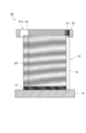
次に、本発明の電池用電極の供給装置の他の実施形態について説明する。図4は、本発明の一実施形態の電池用電極の供給装置30の斜視図である。図1と同じ部材には同符号を付し、その詳細な説明を省略する。
Next, another embodiment of the battery electrode supply device of the present invention will be described. FIG. 4 is a perspective view of the battery electrode supply device 30 according to an embodiment of the present invention. The same members as those in FIG. 1 are denoted by the same reference numerals, and detailed description thereof is omitted.
電池用電極の供給装置30は、マガジン31が枠体32で囲まれて構成されている点で上記の供給装置10と異なる。図4ではガイドシャフト16を設けていないが、設けてもよい。枠体32は、マガジン31の開口部31aからマガジン31の下端まで設けられた平断面コ字型の部材である。枠体32の側面の開口面から電極20をマガジン31に供給することができる。その際、電極の端子部を開口面側に配置する。なお、その開口面に扉を設け、電極20をマガジン31に供給する際に開閉するようにしてもよい。
The battery electrode supply device 30 is different from the above-described supply device 10 in that the magazine 31 is surrounded by a frame 32. Although the guide shaft 16 is not provided in FIG. 4, it may be provided. The frame 32 is a U-shaped member with a flat cross section provided from the opening 31 a of the magazine 31 to the lower end of the magazine 31. The electrode 20 can be supplied to the magazine 31 from the opening on the side surface of the frame 32. In that case, the terminal part of an electrode is arrange | positioned at the opening surface side. A door may be provided on the opening surface, and the door may be opened and closed when the electrode 20 is supplied to the magazine 31.
ブラシ33は、枠体32の内側に電極20の側面へ突出するように設けられ、少なくとも電極20を取り出す際に電極20の外縁に接触し、密着している電極20どうしをさばく役割を有している。図4では、ブラシ33は積み上げられた電極20の端子部を除く電極20の外縁全てに接触するように設けられている。すなわち、ブラシ33は枠体32の上端から下端まで設けられている。なおブラシ33は、必ずしも電極20の端子部を除く電極20の外縁全てに接触する必要はなく、電極20の端子部を除く電極20の外縁の一部に接触する位置に設けた場合でも本発明の効果は得られる。ブラシ33の材料や長さは、上記のブラシ33と同様とすることができる。
The brush 33 is provided inside the frame body 32 so as to protrude to the side surface of the electrode 20, and has a role of touching the outer edges of the electrode 20 at least when the electrode 20 is taken out and separating the electrodes 20 that are in close contact with each other. ing. In FIG. 4, the brush 33 is provided in contact with all the outer edges of the electrode 20 except for the terminal portions of the stacked electrodes 20. That is, the brush 33 is provided from the upper end to the lower end of the frame body 32. Note that the brush 33 is not necessarily in contact with the entire outer edge of the electrode 20 except for the terminal portion of the electrode 20, and the present invention is provided even when the brush 33 is provided at a position in contact with a part of the outer edge of the electrode 20 except for the terminal portion of the electrode 20. The effect is obtained. The material and length of the brush 33 can be the same as those of the brush 33 described above.
供給装置30の動作としては、ステージ17の移動により、最上段の電極20が定位置に保たれる。この状態でバキュームハンド15が下降して最上段の電極20の上面に吸着する。この後、バキュームハンド15が上昇し、吸着した電極20をマガジン31の開口部31a、つまり枠体32から取り出す。このとき、電極20はその外縁がブラシ33の付勢力に抗しながらブラシ33に接触し、ブラシ33を押しのけながら枠体12内を通過する。これにより、電極20が複数枚吸着していた場合、持ち上げられた複数枚の電極20はブラシ33の付勢力によって分離され、最上段の電極20のみが傷が付くことなく取り出される。同時に、ブラシ33によって電極20のバリも除去される。また、電極20のバリはステージ17の移動時にも除去される。
As the operation of the supply device 30, the uppermost electrode 20 is maintained at a fixed position by the movement of the stage 17. In this state, the vacuum hand 15 descends and is attracted to the upper surface of the uppermost electrode 20. Thereafter, the vacuum hand 15 is raised, and the attracted electrode 20 is taken out from the opening 31 a of the magazine 31, that is, the frame body 32. At this time, the outer edge of the electrode 20 contacts the brush 33 while resisting the urging force of the brush 33, and passes through the frame 12 while pushing the brush 33 away. Thus, when a plurality of electrodes 20 are adsorbed, the plurality of lifted electrodes 20 are separated by the urging force of the brush 33, and only the uppermost electrode 20 is taken out without being damaged. At the same time, the burr of the electrode 20 is also removed by the brush 33. Further, the burr of the electrode 20 is removed when the stage 17 is moved.
なお、供給装置10と同様に、バキュームハンド15は電極20を吸着後に枠体32内で複数回昇降し、該昇降時に電極20がブラシ13に接触するようにしてもよい。これにより、電極20の分離をより確実にし、バリ取りの効果も向上する。
Note that, similarly to the supply device 10, the vacuum hand 15 may move up and down a plurality of times within the frame 32 after attracting the electrode 20, and the electrode 20 may come into contact with the brush 13 during the lifting and lowering. Thereby, the separation of the electrode 20 is further ensured, and the effect of deburring is also improved.
次に、本発明の電池用電極の供給装置のさらに他の実施形態について説明する。図5は、本発明の一実施形態の電池用電極の供給装置40の断面図である。図2と同じ部材には同符号を付し、その詳細な説明を省略する。
Next, still another embodiment of the battery electrode supply device of the present invention will be described. FIG. 5 is a cross-sectional view of the battery electrode supply device 40 according to an embodiment of the present invention. The same members as those in FIG. 2 are denoted by the same reference numerals, and detailed description thereof is omitted.
電池用電極の供給装置40は、規制部としてブラシ13の代わりに突条部43を用いている点で上記の供給装置10と異なる。突条部43は、電極20の外縁と略平行に複数並設されている。突条部43は、三角柱の部材であり、1つの頂辺が電極20の側面へ突出するように、枠体12の内側に水平に複数段設けられている。換言すれば、複数の突条部43が並設されていることにより、凹凸による溝が形成されているとも言える。そして、突条部43は少なくとも電極20を取り出す際に電極20の外縁に接触し、密着している電極20どうしをさばく役割を有している。
The battery electrode supply device 40 is different from the above-described supply device 10 in that a protruding portion 43 is used instead of the brush 13 as a regulating portion. A plurality of protrusions 43 are arranged in parallel with the outer edge of the electrode 20. The protrusion 43 is a triangular prism member, and is provided in a plurality of stages horizontally on the inner side of the frame body 12 so that one top side protrudes to the side surface of the electrode 20. In other words, it can be said that a plurality of protrusions 43 are arranged side by side, so that grooves due to irregularities are formed. And the protrusion 43 has a role which contacts the outer edge of the electrode 20 at the time of taking out the electrode 20 at least, and discriminates the electrodes 20 which are closely_contact | adhered.
なお、突条部43の断面形状は三角形に限らず、四角形等の多角形や先端が円弧状となった形状などでもよい。また突条部43は少なくとも2以上並設されていればよいが、その数が多いほど効果が大きい。
The cross-sectional shape of the protrusion 43 is not limited to a triangle, but may be a polygon such as a quadrangle or a shape whose tip is an arc. Moreover, although the protrusion part 43 should just be arranged at least 2 or more in parallel, an effect is so large that the number is large.
図5では、突条部43は電極20の端子部を除く電極20の外縁全てに接触するように設けられている。なお突条部43は、必ずしも電極20の端子部を除く電極20の外縁全てに接触する必要はなく、電極20の端子部を除く電極20の外縁の一部に接触する位置に設けた場合でも本発明の効果は得られる。突条部43の材料や突出の長さは、上記のブラシ13と同様とすることができる。
In FIG. 5, the protrusion 43 is provided so as to be in contact with all the outer edges of the electrode 20 except for the terminal portion of the electrode 20. The protrusion 43 does not necessarily need to be in contact with the entire outer edge of the electrode 20 except for the terminal portion of the electrode 20, and even when provided at a position in contact with a part of the outer edge of the electrode 20 except for the terminal portion of the electrode 20. The effect of the present invention can be obtained. The material of the protrusion 43 and the length of the protrusion can be the same as those of the brush 13 described above.
供給装置40の動作としては、ステージ17の移動により、少なくとも最上段の電極20が突条部43に接触した状態に保たれるか、最上段の電極20が突条部43の下方に位置した状態に保たれる。この状態でバキュームハンド15が下降して最上段の電極20の上面に吸着する。この後、バキュームハンド15が上昇し、吸着した電極20をマガジン41の開口部41a、つまり枠体12から取り出す。このとき、電極20はその外縁が突条部43の付勢力に抗しながら突条部43に下側から接触し、突条部43を押しのけながら枠体12内を通過する。これにより、電極20が複数枚吸着していた場合、持ち上げられた複数枚の電極20は突条部43の付勢力によって分離され、最上段の電極20のみが傷が付くことなく取り出される。同時に、突条部43によって電極20のバリも除去される。
As the operation of the supply device 40, at least the uppermost electrode 20 is kept in contact with the ridge 43 by the movement of the stage 17, or the uppermost electrode 20 is positioned below the ridge 43. Kept in a state. In this state, the vacuum hand 15 descends and is attracted to the upper surface of the uppermost electrode 20. Thereafter, the vacuum hand 15 is raised, and the attracted electrode 20 is taken out from the opening 41 a of the magazine 41, that is, the frame body 12. At this time, the outer edge of the electrode 20 comes into contact with the protrusion 43 from below while resisting the urging force of the protrusion 43, and passes through the frame 12 while pushing the protrusion 43 away. Thereby, when a plurality of electrodes 20 are adsorbed, the plurality of lifted electrodes 20 are separated by the urging force of the protrusion 43, and only the uppermost electrode 20 is taken out without being damaged. At the same time, the burrs of the electrode 20 are also removed by the protrusions 43.
なお、バキュームハンド15は電極20を吸着後に枠体12内を含む位置で複数回昇降し、該昇降時に電極20が突条部43に接触するようにしてもよい。これにより、電極20の分離をより確実にし、バリ取りの効果も向上する。
The vacuum hand 15 may be moved up and down a plurality of times at a position including the inside of the frame 12 after the electrode 20 is sucked, and the electrode 20 may contact the protrusion 43 during the lifting and lowering. Thereby, the separation of the electrode 20 is further ensured, and the effect of deburring is also improved.
本発明は、二次電池をはじめとする各種電池の電極を製造ラインに供給するための供給装置に利用することができる。
The present invention can be used for a supply device for supplying electrodes of various batteries including a secondary battery to a production line.
10、30、40 電池用電極の供給装置
11、31、41 マガジン
11a、31a、41a 開口部
12、32 枠体
13、33 ブラシ
15 バキュームハンド
16 ガイドシャフト
17 ステージ
20 電極
43 突条部 10, 30, 40 Battery electrode supply device 11, 31, 41 Magazine 11a, 31a, 41a Opening 12, 32 Frame 13, 33 Brush 15 Vacuum hand 16 Guide shaft 17 Stage 20 Electrode 43 Projection
11、31、41 マガジン
11a、31a、41a 開口部
12、32 枠体
13、33 ブラシ
15 バキュームハンド
16 ガイドシャフト
17 ステージ
20 電極
43 突条部 10, 30, 40 Battery
Claims (6)
- 上端に開口部を有し、板状の電極を積み重ねて収容するマガジンと、
前記開口部から前記電極を吸着して取り出すバキュームハンドと、
少なくとも前記電極を取り出す際に電極の外縁に接触する規制部とを備え、
前記規制部は、ブラシ又は前記電極の外縁と略平行に並設された複数の突条部であることを特徴とする電池用電極の供給装置。 A magazine having an opening at the upper end and stacking and accommodating plate-like electrodes;
A vacuum hand that sucks and takes out the electrode from the opening;
Comprising at least a regulating portion that contacts an outer edge of the electrode when the electrode is taken out,
The battery electrode supply device according to claim 1, wherein the restricting portion is a brush or a plurality of protrusions arranged substantially parallel to an outer edge of the electrode. - 前記開口部近傍に設けられた又は前記開口部近傍から前記マガジンの下端まで設けられた枠体を備え、
該枠体の内側に前記規制部が設けられたことを特徴とする請求項1記載の電池用電極の供給装置。 A frame provided in the vicinity of the opening or provided from the vicinity of the opening to the lower end of the magazine;
The battery electrode supply device according to claim 1, wherein the restriction portion is provided inside the frame. - 前記電極は端子部を除いて活物質層を有し、
前記規制部は、前記端子部を除く前記電極の外縁全てに接触することを特徴とする請求項1又は2記載の電池用電極の供給装置。 The electrode has an active material layer excluding the terminal portion,
The battery electrode supply device according to claim 1, wherein the restricting portion contacts all outer edges of the electrode except the terminal portion. - 前記マガジンは、前記電極を位置決めするガイドシャフトを有することを特徴とする請求項1~3の何れかに記載の電池用電極の供給装置。 4. The battery electrode supply device according to claim 1, wherein the magazine has a guide shaft for positioning the electrode.
- 前記マガジンは、前記電極を積載して昇降するステージを有することを特徴とする請求項1~4の何れかに記載の電池用電極の供給装置。 The battery electrode supply device according to any one of claims 1 to 4, wherein the magazine has a stage for loading and lowering the electrode.
- 前記バキュームハンドは前記電極を吸着後に複数回昇降し、該昇降時に前記電極が前記規制部に接触することを特徴とする請求項1~5の何れかに記載の電池用電極の供給装置。 The battery electrode supply device according to any one of claims 1 to 5, wherein the vacuum hand moves up and down a plurality of times after adsorbing the electrode, and the electrode comes into contact with the restricting portion during the raising and lowering.
Applications Claiming Priority (2)
| Application Number | Priority Date | Filing Date | Title |
|---|---|---|---|
| JP2012016902A JP2013157197A (en) | 2012-01-30 | 2012-01-30 | Feeding device of electrode for battery |
| JP2012-016902 | 2012-01-30 |
Publications (1)
| Publication Number | Publication Date |
|---|---|
| WO2013114659A1 true WO2013114659A1 (en) | 2013-08-08 |
Family
ID=48904727
Family Applications (1)
| Application Number | Title | Priority Date | Filing Date |
|---|---|---|---|
| PCT/JP2012/072692 WO2013114659A1 (en) | 2012-01-30 | 2012-09-06 | Device for supplying cell electrode |
Country Status (2)
| Country | Link |
|---|---|
| JP (1) | JP2013157197A (en) |
| WO (1) | WO2013114659A1 (en) |
Cited By (4)
| Publication number | Priority date | Publication date | Assignee | Title |
|---|---|---|---|---|
| CN103601014A (en) * | 2013-11-20 | 2014-02-26 | 合肥凯邦电机有限公司 | Feeding device of wave washers |
| WO2016002798A1 (en) * | 2014-06-30 | 2016-01-07 | エリーパワー株式会社 | Apparatus for supplying electrode plate of secondary cell, and method for controlling said apparatus |
| CN111816931A (en) * | 2019-11-29 | 2020-10-23 | 合肥国轩高科动力能源有限公司 | Continuous production device for laminated batteries |
| CN114148756A (en) * | 2022-02-08 | 2022-03-08 | 徐州申通木业有限公司 | Automatic feeding machine for plate production and manufacturing |
Families Citing this family (5)
| Publication number | Priority date | Publication date | Assignee | Title |
|---|---|---|---|---|
| JP6344159B2 (en) * | 2014-09-01 | 2018-06-20 | 株式会社豊田自動織機 | Method for manufacturing electrode assembly |
| JP6544195B2 (en) * | 2015-10-23 | 2019-07-17 | 株式会社村田製作所 | Electrode foil conveying apparatus and laminated battery manufacturing apparatus |
| JP6819850B2 (en) * | 2016-06-01 | 2021-01-27 | 大日本印刷株式会社 | Sheet paper lifting device and sheet sheet lifting method |
| KR101818076B1 (en) | 2016-08-04 | 2018-01-12 | 안혁 | Magazine for Stacking Secondary Battery Cell |
| CN106429431A (en) * | 2016-10-19 | 2017-02-22 | 无锡百立德自动化有限公司 | Pole piece feeding device of lithium battery cell piece stacking machine |
Citations (3)
| Publication number | Priority date | Publication date | Assignee | Title |
|---|---|---|---|---|
| JPS5719243A (en) * | 1980-07-10 | 1982-02-01 | Iwatsu Electric Co Ltd | Automatic paper feeder for duplicator |
| JPS6439334U (en) * | 1987-09-02 | 1989-03-09 | ||
| JP2001313065A (en) * | 2000-05-01 | 2001-11-09 | Toshiba Battery Co Ltd | Feeder of electrode sheet for cell |
-
2012
- 2012-01-30 JP JP2012016902A patent/JP2013157197A/en active Pending
- 2012-09-06 WO PCT/JP2012/072692 patent/WO2013114659A1/en active Application Filing
Patent Citations (3)
| Publication number | Priority date | Publication date | Assignee | Title |
|---|---|---|---|---|
| JPS5719243A (en) * | 1980-07-10 | 1982-02-01 | Iwatsu Electric Co Ltd | Automatic paper feeder for duplicator |
| JPS6439334U (en) * | 1987-09-02 | 1989-03-09 | ||
| JP2001313065A (en) * | 2000-05-01 | 2001-11-09 | Toshiba Battery Co Ltd | Feeder of electrode sheet for cell |
Cited By (7)
| Publication number | Priority date | Publication date | Assignee | Title |
|---|---|---|---|---|
| CN103601014A (en) * | 2013-11-20 | 2014-02-26 | 合肥凯邦电机有限公司 | Feeding device of wave washers |
| CN103601014B (en) * | 2013-11-20 | 2016-08-24 | 合肥凯邦电机有限公司 | The discharging device of wave washer |
| WO2016002798A1 (en) * | 2014-06-30 | 2016-01-07 | エリーパワー株式会社 | Apparatus for supplying electrode plate of secondary cell, and method for controlling said apparatus |
| TWI645594B (en) * | 2014-06-30 | 2018-12-21 | 日商艾利電力能源有限公司 | Supply device for electrode plate of secondary battery and control method thereof |
| CN111816931A (en) * | 2019-11-29 | 2020-10-23 | 合肥国轩高科动力能源有限公司 | Continuous production device for laminated batteries |
| CN111816931B (en) * | 2019-11-29 | 2022-09-13 | 合肥国轩高科动力能源有限公司 | Continuous production device for laminated batteries |
| CN114148756A (en) * | 2022-02-08 | 2022-03-08 | 徐州申通木业有限公司 | Automatic feeding machine for plate production and manufacturing |
Also Published As
| Publication number | Publication date |
|---|---|
| JP2013157197A (en) | 2013-08-15 |
Similar Documents
| Publication | Publication Date | Title |
|---|---|---|
| WO2013114659A1 (en) | Device for supplying cell electrode | |
| KR101389609B1 (en) | Lithium secondary battery and use thereof | |
| JP4893254B2 (en) | Lithium secondary battery manufacturing method and lithium secondary battery | |
| EP2680361A1 (en) | Jelly roll-type electrode assembly with active material pattern-coated thereon, and secondary battery having same | |
| JP2011204660A (en) | Lithium secondary battery | |
| CN101150183A (en) | A coiling lithium secondary battery | |
| JP2011070976A (en) | Lithium ion secondary battery, vehicle, and battery loading equipment | |
| CN104412438A (en) | Secondary cell | |
| WO2022198682A1 (en) | Electrode assembly, battery cell, battery, and method and device for manufacturing electrode assembly | |
| EP3614477A1 (en) | Electrode assembly and battery comprising same | |
| US20020094478A1 (en) | Electrode with flag-shaped tab | |
| KR101773103B1 (en) | Electrode, a method for preparing the same, electrode prepared using the same and secondary battery containing the same | |
| KR102363963B1 (en) | Lithium secondary battery | |
| KR101610431B1 (en) | Electrode assembly of jelly roll type and secondary battery comprising the same | |
| CN116072817B (en) | Electrochemical device and electricity using device | |
| JP2011222128A (en) | Secondary battery | |
| JP2023509174A (en) | battery cells, batteries and electronic devices | |
| US20230021075A1 (en) | Battery cell, method and system for manufacturing same, battery, and electrical device | |
| US9356294B2 (en) | Secondary battery including collectors with pores and manufacturing method thereof | |
| KR101520345B1 (en) | Three dimensional electrode assembly and manufacturing method of the same | |
| JP6050954B2 (en) | Nonaqueous electrolyte secondary battery | |
| CN114730961B (en) | Electrochemical device and electric equipment | |
| US20160049651A1 (en) | Negative electrode for nonaqueous electrolyte secondary battery and nonaqueous electrolyte secondary battery | |
| KR101431726B1 (en) | Electrode Assembly of Improved Safety And Secondary Battery with the Same | |
| JP2023541131A (en) | Electrode assemblies, battery cells, batteries, and methods and devices for manufacturing electrode assemblies |
Legal Events
| Date | Code | Title | Description |
|---|---|---|---|
| 121 | Ep: the epo has been informed by wipo that ep was designated in this application |
Ref document number: 12867134 Country of ref document: EP Kind code of ref document: A1 |
|
| NENP | Non-entry into the national phase |
Ref country code: DE |
|
| 122 | Ep: pct application non-entry in european phase |
Ref document number: 12867134 Country of ref document: EP Kind code of ref document: A1 |