WO2013111288A1 - Vehicle control device - Google Patents
Vehicle control device Download PDFInfo
- Publication number
- WO2013111288A1 WO2013111288A1 PCT/JP2012/051568 JP2012051568W WO2013111288A1 WO 2013111288 A1 WO2013111288 A1 WO 2013111288A1 JP 2012051568 W JP2012051568 W JP 2012051568W WO 2013111288 A1 WO2013111288 A1 WO 2013111288A1
- Authority
- WO
- WIPO (PCT)
- Prior art keywords
- vehicle
- collision prevention
- unit
- control device
- sensor
- Prior art date
Links
Images

Classifications
-
- B—PERFORMING OPERATIONS; TRANSPORTING
- B60—VEHICLES IN GENERAL
- B60T—VEHICLE BRAKE CONTROL SYSTEMS OR PARTS THEREOF; BRAKE CONTROL SYSTEMS OR PARTS THEREOF, IN GENERAL; ARRANGEMENT OF BRAKING ELEMENTS ON VEHICLES IN GENERAL; PORTABLE DEVICES FOR PREVENTING UNWANTED MOVEMENT OF VEHICLES; VEHICLE MODIFICATIONS TO FACILITATE COOLING OF BRAKES
- B60T7/00—Brake-action initiating means
- B60T7/12—Brake-action initiating means for automatic initiation; for initiation not subject to will of driver or passenger
-
- G—PHYSICS
- G08—SIGNALLING
- G08G—TRAFFIC CONTROL SYSTEMS
- G08G1/00—Traffic control systems for road vehicles
- G08G1/16—Anti-collision systems
-
- B—PERFORMING OPERATIONS; TRANSPORTING
- B60—VEHICLES IN GENERAL
- B60R—VEHICLES, VEHICLE FITTINGS, OR VEHICLE PARTS, NOT OTHERWISE PROVIDED FOR
- B60R21/00—Arrangements or fittings on vehicles for protecting or preventing injuries to occupants or pedestrians in case of accidents or other traffic risks
-
- B—PERFORMING OPERATIONS; TRANSPORTING
- B60—VEHICLES IN GENERAL
- B60T—VEHICLE BRAKE CONTROL SYSTEMS OR PARTS THEREOF; BRAKE CONTROL SYSTEMS OR PARTS THEREOF, IN GENERAL; ARRANGEMENT OF BRAKING ELEMENTS ON VEHICLES IN GENERAL; PORTABLE DEVICES FOR PREVENTING UNWANTED MOVEMENT OF VEHICLES; VEHICLE MODIFICATIONS TO FACILITATE COOLING OF BRAKES
- B60T7/00—Brake-action initiating means
- B60T7/12—Brake-action initiating means for automatic initiation; for initiation not subject to will of driver or passenger
- B60T7/22—Brake-action initiating means for automatic initiation; for initiation not subject to will of driver or passenger initiated by contact of vehicle, e.g. bumper, with an external object, e.g. another vehicle, or by means of contactless obstacle detectors mounted on the vehicle
-
- B—PERFORMING OPERATIONS; TRANSPORTING
- B60—VEHICLES IN GENERAL
- B60T—VEHICLE BRAKE CONTROL SYSTEMS OR PARTS THEREOF; BRAKE CONTROL SYSTEMS OR PARTS THEREOF, IN GENERAL; ARRANGEMENT OF BRAKING ELEMENTS ON VEHICLES IN GENERAL; PORTABLE DEVICES FOR PREVENTING UNWANTED MOVEMENT OF VEHICLES; VEHICLE MODIFICATIONS TO FACILITATE COOLING OF BRAKES
- B60T8/00—Arrangements for adjusting wheel-braking force to meet varying vehicular or ground-surface conditions, e.g. limiting or varying distribution of braking force
- B60T8/17—Using electrical or electronic regulation means to control braking
- B60T8/1755—Brake regulation specially adapted to control the stability of the vehicle, e.g. taking into account yaw rate or transverse acceleration in a curve
- B60T8/17558—Brake regulation specially adapted to control the stability of the vehicle, e.g. taking into account yaw rate or transverse acceleration in a curve specially adapted for collision avoidance or collision mitigation
-
- G—PHYSICS
- G08—SIGNALLING
- G08G—TRAFFIC CONTROL SYSTEMS
- G08G1/00—Traffic control systems for road vehicles
- G08G1/16—Anti-collision systems
- G08G1/165—Anti-collision systems for passive traffic, e.g. including static obstacles, trees
-
- G—PHYSICS
- G08—SIGNALLING
- G08G—TRAFFIC CONTROL SYSTEMS
- G08G1/00—Traffic control systems for road vehicles
- G08G1/16—Anti-collision systems
- G08G1/166—Anti-collision systems for active traffic, e.g. moving vehicles, pedestrians, bikes
-
- B—PERFORMING OPERATIONS; TRANSPORTING
- B60—VEHICLES IN GENERAL
- B60T—VEHICLE BRAKE CONTROL SYSTEMS OR PARTS THEREOF; BRAKE CONTROL SYSTEMS OR PARTS THEREOF, IN GENERAL; ARRANGEMENT OF BRAKING ELEMENTS ON VEHICLES IN GENERAL; PORTABLE DEVICES FOR PREVENTING UNWANTED MOVEMENT OF VEHICLES; VEHICLE MODIFICATIONS TO FACILITATE COOLING OF BRAKES
- B60T2201/00—Particular use of vehicle brake systems; Special systems using also the brakes; Special software modules within the brake system controller
- B60T2201/02—Active or adaptive cruise control system; Distance control
- B60T2201/022—Collision avoidance systems
Definitions
- the present invention relates to a vehicle control device including a collision prevention device.
- a vehicle control device including a collision prevention device that performs a collision prevention operation is known.
- the collision prevention device is controlled so that the collision prevention operation is less likely to occur when the vehicle is taking a turning behavior.
- a technique for avoiding a situation in which a curved roadside object such as a guardrail is erroneously detected as an obstacle is disclosed.
- the operation of the collision prevention device may be suppressed when it is not necessary, for example, when the vehicle decelerates during straight running.
- the conventional vehicle control device there is room for improvement in the accuracy of the determination as to whether or not the operation of the collision prevention device should be suppressed.
- an object of the present invention is to provide a vehicle control device that improves the accuracy of the determination as to whether or not the operation of the collision prevention device should be suppressed.
- a vehicle control device that has solved the above problems includes a collision prevention unit that performs a collision prevention operation between a vehicle and an object around the vehicle, and the collision prevention unit operates when a turning behavior of the vehicle is detected.
- the vehicle control device for suppressing the collision includes a control unit that controls the operation of the collision prevention unit so that the operation of the collision prevention unit is not suppressed when the vehicle decelerates.
- the control unit controls the collision prevention unit so as not to suppress the operation of the collision prevention unit. For this reason, the yaw rate fluctuates as the vehicle decelerates, and even if this is detected as a turning behavior, the collision prevention operation is not easily performed. Therefore, it is possible to avoid a situation in which the operation of the collision prevention unit is suppressed when it is not necessary, so that it is possible to improve the accuracy of the determination as to whether or not to suppress the operation of the collision prevention device.
- the control unit controls the operation of the collision prevention unit so as not to suppress the operation of the collision prevention unit when the deceleration of the vehicle is equal to or higher than a reference value.
- the collision prevention unit does not easily operate, and unnecessary operation suppression associated with deceleration can be avoided.
- the control unit controls the operation of the collision prevention unit so as not to suppress the operation of the collision prevention unit when the brake of the vehicle is operated. According to the present invention, when the brake is operated, the collision prevention operation is not easily performed, and thus unnecessary operation suppression can be avoided with a simple configuration.
- the vehicle control device further includes a deceleration unit that automatically decelerates the vehicle, and the control unit prevents collision so as not to suppress the operation of the collision prevention unit when the deceleration unit decelerates the vehicle. It is preferable to control the operation of the unit. According to the present invention, even if a safety system such as a PCS (Pre-crashsafety system) that performs collision avoidance control is installed, it is not difficult to perform the collision prevention operation during deceleration. It is possible to further improve the accuracy of determination as to whether or not to suppress the operation of the collision prevention device by avoiding the suppression.
- a safety system such as a PCS (Pre-crashsafety system) that performs collision avoidance control
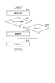
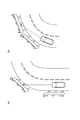
- FIG. 1 It is a block diagram which shows the vehicle control apparatus which concerns on embodiment of this invention. It is a flowchart which shows the obstruction determination process performed by the vehicle control apparatus shown in FIG. It is a figure for demonstrating the condition where the action suppression of a collision prevention part is performed.
- the vehicle control device 1 As shown in FIG. 1, the vehicle control device 1 according to the present embodiment is mounted on a vehicle 100 and detects information around the vehicle 100, a traveling state of the vehicle 100, and the like, and detects a collision with an object around the vehicle 100. PCS function to prevent.
- the vehicle control device 1 includes a collision prevention unit 82 that performs a collision prevention operation between the vehicle 100 and an object around the vehicle 100, and suppresses the operation of the collision prevention unit 82 when a turning behavior of the vehicle 100 is detected. It is. Further, the vehicle control device 1 includes a control unit 84 that controls the operation of the collision prevention unit 82 so as not to suppress the operation of the collision prevention unit 82 when the vehicle 100 decelerates.
- the collision prevention unit 82 and the control unit 84 are mounted on, for example, an ECU (Electronic Control Unit) 8.
- the vehicle control apparatus 1 is comprised including the millimeter wave sensor 2, the vehicle sensor 3, and ECU8, for example.
- the millimeter wave sensor 2 functions as a radar detection unit that receives a reflected wave of the emitted electromagnetic wave and acquires detection points on objects around the vehicle 100.
- the millimeter wave sensor 2 is attached to the front and side of the vehicle 100, scans the front and side of the vehicle 100 with electromagnetic waves in the millimeter wave band, and reflects the electromagnetic wave reflected on the surface of an object existing around the vehicle 100. Receive. Thereby, the millimeter wave sensor 2 recognizes the target as an electromagnetic wave reflection point.
- the millimeter wave sensor 2 also acquires target information (radar target information) from millimeter wave transmission / reception data.
- the radar target information is, for example, the lateral position of the target, the distance between the vehicle 100 and the target, and the relative speed between the vehicle 100 and the target.
- the millimeter wave sensor 2 is connected to the ECU 8, and radar target information acquired by the millimeter wave sensor 2 is input to the ECU 8.
- the vehicle sensor 3 functions as a traveling state detection unit that detects the traveling state of the vehicle 100.
- the vehicle sensor 3 includes, for example, a brake sensor 31, a speed sensor 32, an acceleration sensor 33, and a yaw rate sensor 34.
- the vehicle sensor 3 is connected to the ECU 8, and the traveling state of the vehicle 100 acquired by the vehicle sensor 3 is input to the ECU 8.
- the brake sensor 31 has a function of detecting whether or not the brake pedal has been operated by the driver of the vehicle 100.
- the brake sensor 31 detects the operation state of the brake pedal by the driver, and transmits the detected operation state of the brake pedal to the ECU 8 as a brake signal.
- the speed sensor 32 has a function of detecting the speed of the vehicle 100 and is provided, for example, on a wheel of the vehicle 100. For example, the speed sensor 32 detects the rotational speed of the wheel and calculates the vehicle speed of the vehicle 100 from the rotational speed. The speed sensor 32 transmits the detected vehicle speed of the vehicle 100 to the ECU 8.
- the acceleration sensor 33 has a function of detecting the degree of acceleration and deceleration of the vehicle 100.
- the acceleration sensor 33 is provided in the front part of the vehicle 100, for example, and detects the longitudinal acceleration / deceleration and the lateral acceleration / deceleration of the vehicle 100.
- the acceleration sensor 33 transmits the detected acceleration / deceleration to the ECU 8.
- the yaw rate sensor 34 has a function of detecting the yaw rate of the vehicle 100.
- the yaw rate sensor 34 transmits the detected yaw rate to the ECU 8 as a yaw rate signal.
- the ECU 8 determines whether or not there is an obstacle around the vehicle 100 from each information acquired by the millimeter wave sensor 2 and the vehicle sensor 3, and the collision prevention operation when it is determined that the obstacle exists.
- a PCS function is provided.
- the ECU 8 is a computer including, for example, a CPU (Central Processing Unit) and a memory such as a ROM (Read Only Memory) and a RAM (Random Access Memory), and includes an input signal circuit, an output signal circuit, and a power supply circuit. Composed. In the ECU 8, for example, an application stored in the ROM is loaded into the RAM and executed by the CPU.
- a conventional vehicle control device will be described as a comparative example of the vehicle control device 1 of the present embodiment.
- the conventional collision prevention operation for example, when the vehicle is positioned at the entrance of the curve as shown in FIG. 3 (a), and the vehicle is about to run on the curve, or as shown in FIG. 3 (b), When traveling on a curve, a roadside object such as a guardrail may be erroneously detected as an obstacle.
- the operation of the collision prevention device is suppressed so that the collision prevention operation is difficult to be performed when the vehicle is taking a turning behavior.
- the vehicle control apparatus has a problem that the operation of the unnecessary collision prevention apparatus is suppressed.
- the ECU 8 includes an obstacle determination unit 81, a collision prevention unit 82, a turning behavior detection unit 83, a control unit 84, and a speed reduction unit 85.
- the control unit 84 controls the operation of the collision prevention unit 82 so as not to suppress the operation of the collision prevention unit 82 during vehicle deceleration.
- the obstacle determination unit 81, the collision prevention unit 82, the turning behavior detection unit 83, the control unit 84, and the speed reduction unit 85 are not built in the same ECU 8 as described above, but are built in different ECUs. It may be.
- the obstacle determination unit 81 detects an object around the vehicle 100 from the information acquired by the millimeter wave sensor 2 and determines whether there is an obstacle around the vehicle 100 using the traveling state acquired by the vehicle sensor 3. To do. Specifically, the obstacle determination unit 81 calculates the collision risk between the vehicle 100 and an object around the vehicle 100 using the information acquired by the millimeter wave sensor 2 and the vehicle sensor 3. It is determined that there is an obstacle when it is equal to or greater than a predetermined threshold. As information acquired by the millimeter wave sensor 2, for example, the lateral position of an object around the vehicle 100 can be used. In this case, when the lateral position detected by the millimeter wave sensor 2 is less than a predetermined threshold value, It is determined that there is an object, and it is determined that there is no obstacle when it is equal to or greater than the threshold.
- the collision prevention unit 82 performs a collision prevention operation between the vehicle 100 and an object around the vehicle 100.
- the collision prevention unit 82 outputs an alarm to the driver of the vehicle 100, for example, when the obstacle determination unit 81 determines that an obstacle exists around the vehicle 100.
- Examples of the collision prevention operation performed by the collision prevention unit 82 include deceleration of the vehicle 100 by the deceleration unit 85 and winding of the seat belt.
- the turning behavior detection unit 83 has a function of detecting the turning behavior of the vehicle 100.
- the turning behavior detection unit 83 detects the turning behavior based on the traveling state of the vehicle 100 acquired by the vehicle sensor 3. Specifically, for example, when the vehicle 100 turns and the yaw rate detected by the yaw rate sensor 34 exceeds a predetermined value, the turning behavior detection unit 83 detects the turning as the turning behavior.
- the control unit 84 controls the operation of the collision prevention unit 82, and controls the collision prevention unit 82 so as not to suppress the operation of the collision prevention unit 82 when the vehicle 100 decelerates. Specifically, the control unit 84 sets the determination threshold value of the obstacle determination unit 81 so that the collision prevention unit 82 becomes difficult to operate when the turning behavior is detected, and the collision prevention is performed when the vehicle 100 is decelerated.
- the determination threshold value of the obstacle determination unit 81 is changed so that the unit 82 can be easily operated.
- the control unit 84 decreases the determination threshold when detecting the turning behavior so that it is difficult to determine that there is an obstacle, and increases the determination threshold when the vehicle 100 decelerates.
- the operation of the collision prevention unit 82 is controlled so that it is easy to determine that there is an obstacle.
- control unit 84 controls the operation of the collision prevention unit 82 so as not to suppress the operation of the collision prevention unit 82 when the brake of the vehicle 100 is operated.
- the brake operation of the vehicle 100 here may be a driver's brake operation detected by the brake sensor 31 or a brake operation that is automatically executed.
- the deceleration unit 85 has a function of automatically decelerating the vehicle 100.
- the deceleration unit 85 functions as part of the PCS collision prevention operation, and decelerates the vehicle 100 when the obstacle determination unit 81 determines that an obstacle is present.
- the process shown in FIG. 2 is executed by the ECU 8 and is an obstacle determination process for determining whether there is an obstacle around the vehicle 100.
- This obstacle determination process is repeatedly executed at regular intervals while the vehicle 100 is traveling, for example.
- step S10 (hereinafter referred to as “S10”, the same applies to other steps), various information reading processing is executed. Specifically, the detection results of the millimeter wave sensor 2 and the vehicle sensor 3 are transmitted to the ECU 8 and stored in the memory of the ECU 8. After the process of S10 is completed, the process proceeds to S12.
- a brake operation determination process for determining whether or not the brake is operating is executed. Specifically, it is determined whether or not automatic braking by the deceleration unit 85 is operating. Here, when it determines with it not operating, it transfers to S14, and when it determines with it operating, it transfers to S16. Note that, in S12, instead of determining whether or not the automatic brake by the speed reduction unit 85 is operating, it may be determined whether or not a brake operation is being performed by the driver of the vehicle 100.
- a deceleration determination process for determining whether or not the deceleration of the vehicle 100 is greater than or equal to a reference value is executed. Specifically, the ECU 8 detects the deceleration of the vehicle 100 based on the detection result of the acceleration sensor 33, and it is determined whether or not the deceleration of the vehicle 100 is equal to or greater than the threshold value A. If it is determined that the threshold value A is equal to or greater than the threshold value A, the process proceeds to S16.
- the value of the threshold A is not particularly limited, but can be set to, for example, 0.3 [G]. Further, the value of the threshold A may be appropriately determined from the relationship among the deceleration of the vehicle 100, the pitching angle, and the vertical angle of the millimeter wave, for example.
- a threshold setting process by the control unit 84 is executed. Specifically, the control unit 84 sets a threshold value so that the collision prevention operation of the collision prevention unit 82 is easily performed.
- the control unit 84 sets a higher threshold, and the threshold, for example, ⁇ 0.5 [m] is changed to ⁇ 1.0 [m]. Is done.
- the threshold value By changing the threshold value, it is easy to determine whether there is an obstacle and to perform the collision prevention operation of the collision prevention unit 82.
- the process proceeds to S18.
- the obstacle determination unit 81 executes an obstacle presence / absence determination process. Specifically, the obstacle determination unit 81 compares the detection results of the millimeter wave sensor 2 and the vehicle sensor 3 with the above threshold value to determine the presence or absence of an obstacle. For example, when the obstacle is determined based on the lateral position, the obstacle determining unit 81 determines that there is an obstacle when the lateral position of the object around the vehicle 100 is equal to or less than the threshold, and the lateral position is less than the threshold. When it is larger, it is judged that there is no obstacle.
- the collision prevention operation of the collision prevention unit 82 is executed.
- the deceleration of the vehicle 100 by the deceleration unit 85 For example, the deceleration of the vehicle 100 by the deceleration unit 85, a warning to the driver of the vehicle 100, or the winding of the seat belt, etc. Done. In this way, a series of processing ends after finishing the processing of S18.
- the collision prevention unit 82 that performs the collision prevention operation between the vehicle 100 and the objects around the vehicle 100 is provided, and the operation of the collision prevention unit 82 is detected when the turning behavior of the vehicle 100 is detected.
- the vehicle control device 1 for suppressing the collision is provided with a control unit 84 that controls the operation of the collision prevention unit 82 so as not to suppress the operation of the collision prevention unit 82 when the vehicle 100 decelerates.
- the vehicle control device 1 of the present embodiment controls the operation of the collision prevention unit so that the collision prevention operation is not easily performed when the vehicle 100 is decelerated. For this reason, in the case where it fluctuates with deceleration and is detected as a turning behavior, the suppression of the operation of the collision prevention unit 82 is alleviated. Therefore, it is possible to avoid a situation in which the operation of the collision prevention unit 82 is suppressed when it is not necessary, such as when the vehicle 100 is decelerated. Can be improved.
- the control unit 84 operates the collision prevention unit 82 so as not to suppress the operation of the collision prevention unit 82 when the deceleration of the vehicle 100 is equal to or greater than the threshold A.
- the control part 84 which performs control is provided. Therefore, when the deceleration of the vehicle 100 is greater than or equal to the threshold A, the suppression of the operation of the collision prevention unit 82 is alleviated, so that unnecessary suppression of the operation can be avoided.
- the control unit 84 controls the operation of the collision prevention unit 82 so as not to suppress the operation of the collision prevention unit 82 when the brake of the vehicle 100 is operated. Therefore, since the suppression of the operation of the collision prevention unit 82 is alleviated when the brake is operated, unnecessary suppression of the operation can be avoided with a simple configuration.
- the speed reduction unit 85 that automatically decelerates the vehicle 100 is provided, and the control unit 84 includes a collision prevention unit 82 when the speed reduction unit 85 decelerates the vehicle 100.
- the operation control of the collision prevention unit 82 is performed so as not to suppress the operation of. Therefore, even when a safety system such as PCS that performs collision avoidance control is installed, unnecessary operation suppression can be avoided because the collision prevention operation does not become difficult during deceleration.
- embodiment mentioned above demonstrates embodiment of the vehicle control apparatus which concerns on this invention, and the vehicle control apparatus which concerns on this invention is not limited to what was described in this embodiment.
- the vehicle control device according to the present invention may be modified from the vehicle control device according to the present embodiment or applied to other devices without changing the gist described in each claim.
- the determination as to whether the PCS brake is operating and the determination as to whether the deceleration of the vehicle 100 is greater than or equal to the threshold A may be executed.
- the obstacle determination is performed so that the control unit 84 can easily perform the collision prevention operation of the collision prevention unit 82.
- the example of changing the determination threshold value of the unit 81 has been described.
- the technique for facilitating the collision prevention operation is not limited to this.
- the determination threshold value may be calculated each time based on at least one of the deceleration of the vehicle 100 and the brake operation status of the vehicle 100, and the threshold value may be set dynamically. In this way, the operation control of the collision prevention unit 82 can be performed with higher accuracy.
- the example using the millimeter wave sensor 2 has been described.
- a sensor having a different wavelength band such as a sensor using a microwave or a submillimeter wave may be used.
- Any sensor can be used as a substitute for the millimeter wave sensor 2 as long as it can measure the positional relationship between the vehicle 100 and an object around the vehicle 100.
- SYMBOLS 1 Vehicle control apparatus, 2 ... Millimeter wave sensor, 3 ... Vehicle sensor, 8 ... ECU, 31 ... Brake sensor, 32 ... Speed sensor, 33 ... Acceleration sensor, 34 ... Yaw rate sensor, 81 ... Obstacle determination part, 82 ... Collision prevention unit, 83 ... turning behavior detection unit, 84 ... control unit, 85 ... deceleration unit, 100 ... vehicle, A ... threshold.
Abstract
Description
Claims (4)
- 車両と前記車両の周囲の物体との衝突予防動作を行う衝突防止部を備え、前記車両の旋回挙動が検出された場合に前記衝突防止部の作動を抑制する車両制御装置において、
前記車両が減速した場合に前記衝突防止部の作動を抑制しないように前記衝突防止部の作動制御を行う制御部を備える車両制御装置。 In a vehicle control device comprising a collision prevention unit that performs a collision prevention operation between a vehicle and an object around the vehicle, and suppressing the operation of the collision prevention unit when a turning behavior of the vehicle is detected,
A vehicle control device provided with a control part which controls operation of the collision prevention part so that operation of the collision prevention part is not controlled when the vehicle decelerates. - 前記制御部は、前記車両の減速度が基準値以上である場合に前記衝突防止部の作動を抑制しないように前記衝突防止部の作動制御を行う、
請求項1に記載の車両制御装置。 The control unit performs operation control of the collision prevention unit so as not to suppress the operation of the collision prevention unit when the deceleration of the vehicle is equal to or higher than a reference value.
The vehicle control device according to claim 1. - 前記制御部は、前記車両のブレーキが作動した場合に前記衝突防止部の作動を抑制しないように前記衝突防止部の作動制御を行う、
請求項1又は2に記載の車両制御装置。 The control unit performs operation control of the collision prevention unit so as not to suppress the operation of the collision prevention unit when a brake of the vehicle is operated.
The vehicle control device according to claim 1 or 2. - 自動的に前記車両を減速させる減速部を備え、
前記制御部は、前記減速部が前記車両を減速させている場合に前記衝突防止部の作動を抑制しないように前記衝突防止部の作動制御を行う、
請求項1~3のいずれか1項に記載の車両制御装置。 A decelerating portion for automatically decelerating the vehicle;
The control unit performs operation control of the collision prevention unit so as not to suppress the operation of the collision prevention unit when the speed reduction unit decelerates the vehicle.
The vehicle control device according to any one of claims 1 to 3.
Priority Applications (9)
| Application Number | Priority Date | Filing Date | Title |
|---|---|---|---|
| JP2013555050A JP5673863B2 (en) | 2012-01-25 | 2012-01-25 | Vehicle control device |
| AU2012367639A AU2012367639A1 (en) | 2012-01-25 | 2012-01-25 | Vehicle control device |
| BR112014018014A BR112014018014A8 (en) | 2012-01-25 | 2012-01-25 | VEHICLE CONTROLLER |
| EP12866819.1A EP2808854B1 (en) | 2012-01-25 | 2012-01-25 | Vehicle control device |
| KR1020147020745A KR20140107605A (en) | 2012-01-25 | 2012-01-25 | Vehicle control device |
| CN201280067817.XA CN104067328B (en) | 2012-01-25 | 2012-01-25 | Vehicle control device |
| RU2014130230/11A RU2581897C2 (en) | 2012-01-25 | 2012-01-25 | Device for vehicle control |
| US14/372,859 US9522656B2 (en) | 2012-01-25 | 2012-01-25 | Vehicle controller |
| PCT/JP2012/051568 WO2013111288A1 (en) | 2012-01-25 | 2012-01-25 | Vehicle control device |
Applications Claiming Priority (1)
| Application Number | Priority Date | Filing Date | Title |
|---|---|---|---|
| PCT/JP2012/051568 WO2013111288A1 (en) | 2012-01-25 | 2012-01-25 | Vehicle control device |
Publications (1)
| Publication Number | Publication Date |
|---|---|
| WO2013111288A1 true WO2013111288A1 (en) | 2013-08-01 |
Family
ID=48873059
Family Applications (1)
| Application Number | Title | Priority Date | Filing Date |
|---|---|---|---|
| PCT/JP2012/051568 WO2013111288A1 (en) | 2012-01-25 | 2012-01-25 | Vehicle control device |
Country Status (9)
| Country | Link |
|---|---|
| US (1) | US9522656B2 (en) |
| EP (1) | EP2808854B1 (en) |
| JP (1) | JP5673863B2 (en) |
| KR (1) | KR20140107605A (en) |
| CN (1) | CN104067328B (en) |
| AU (1) | AU2012367639A1 (en) |
| BR (1) | BR112014018014A8 (en) |
| RU (1) | RU2581897C2 (en) |
| WO (1) | WO2013111288A1 (en) |
Cited By (2)
| Publication number | Priority date | Publication date | Assignee | Title |
|---|---|---|---|---|
| JP2018095112A (en) * | 2016-12-14 | 2018-06-21 | 株式会社Soken | Deceleration control device and deceleration control method |
| US10854081B2 (en) | 2015-12-25 | 2020-12-01 | Denso Corporation | Driving assistance device and driving assistance method |
Families Citing this family (2)
| Publication number | Priority date | Publication date | Assignee | Title |
|---|---|---|---|---|
| US10137893B2 (en) * | 2016-09-26 | 2018-11-27 | Keith J. Hanna | Combining driver alertness with advanced driver assistance systems (ADAS) |
| CN108922245B (en) * | 2018-07-06 | 2021-03-09 | 北京中交华安科技有限公司 | Early warning method and system for road section with poor sight distance |
Citations (8)
| Publication number | Priority date | Publication date | Assignee | Title |
|---|---|---|---|---|
| JPH07296298A (en) * | 1994-04-20 | 1995-11-10 | Nippondenso Co Ltd | Warning device for distance between vihicles |
| JP2000198402A (en) | 1999-01-05 | 2000-07-18 | Sumitomo Electric Ind Ltd | Object detector |
| JP2000298800A (en) | 1999-04-13 | 2000-10-24 | Takata Corp | Device measuring distance between vehicles and collision warning device |
| JP2008018832A (en) | 2006-07-12 | 2008-01-31 | Fuji Heavy Ind Ltd | Vehicle motion controller |
| JP2008174055A (en) * | 2007-01-17 | 2008-07-31 | Mitsubishi Electric Corp | Occupant crash protection device |
| JP2008293438A (en) * | 2007-05-28 | 2008-12-04 | Toyota Motor Corp | Collision preventive device |
| JP2010015450A (en) | 2008-07-04 | 2010-01-21 | Toyota Motor Corp | Collision-avoiding system |
| WO2011125168A1 (en) * | 2010-04-05 | 2011-10-13 | トヨタ自動車株式会社 | Vehicle collision judgment device |
Family Cites Families (12)
| Publication number | Priority date | Publication date | Assignee | Title |
|---|---|---|---|---|
| US5631639A (en) * | 1994-04-20 | 1997-05-20 | Nippondenso Co., Ltd. | Collision alarm system for automotive vehicle |
| JP2002019490A (en) | 2000-07-06 | 2002-01-23 | Nissan Motor Co Ltd | Reduction gear of vehicle |
| EP1412930B1 (en) | 2001-07-11 | 2008-03-26 | Robert Bosch Gmbh | Method and device for automatically triggering deceleration of a vehicle |
| US7099759B2 (en) * | 2004-03-30 | 2006-08-29 | General Motors Corporation | Method and apparatus for estimating steering behavior for integrated chassis control |
| JP4391304B2 (en) * | 2004-04-23 | 2009-12-24 | 日産自動車株式会社 | Deceleration control device |
| JP4067541B2 (en) * | 2005-07-04 | 2008-03-26 | トヨタ自動車株式会社 | Vehicle control device and vehicle vibration control method |
| RU2305641C1 (en) * | 2005-11-29 | 2007-09-10 | РЯЗАНСКИЙ ВОЕННЫЙ АВТОМОБИЛЬНЫЙ ИНСТИТУТ им. генерала армии В.П. Дубынина | Automatic device to prevent collision of vehicles |
| JP4169065B2 (en) * | 2006-02-13 | 2008-10-22 | 株式会社デンソー | Vehicle control device |
| JP4222398B2 (en) * | 2006-09-21 | 2009-02-12 | 株式会社デンソー | Vehicle collision determination device |
| JP4595932B2 (en) * | 2006-12-08 | 2010-12-08 | トヨタ自動車株式会社 | Vehicle control device |
| EP2130193A2 (en) * | 2007-02-26 | 2009-12-09 | Toyota Jidosha Kabushiki Kaisha | Inter-vehicle communication system and method for indicating speed and deceleration |
| JP5258862B2 (en) * | 2010-10-19 | 2013-08-07 | キヤノン株式会社 | Image forming apparatus |
-
2012
- 2012-01-25 BR BR112014018014A patent/BR112014018014A8/en not_active IP Right Cessation
- 2012-01-25 EP EP12866819.1A patent/EP2808854B1/en active Active
- 2012-01-25 JP JP2013555050A patent/JP5673863B2/en active Active
- 2012-01-25 US US14/372,859 patent/US9522656B2/en active Active
- 2012-01-25 AU AU2012367639A patent/AU2012367639A1/en not_active Abandoned
- 2012-01-25 WO PCT/JP2012/051568 patent/WO2013111288A1/en active Application Filing
- 2012-01-25 RU RU2014130230/11A patent/RU2581897C2/en not_active IP Right Cessation
- 2012-01-25 KR KR1020147020745A patent/KR20140107605A/en not_active Application Discontinuation
- 2012-01-25 CN CN201280067817.XA patent/CN104067328B/en active Active
Patent Citations (8)
| Publication number | Priority date | Publication date | Assignee | Title |
|---|---|---|---|---|
| JPH07296298A (en) * | 1994-04-20 | 1995-11-10 | Nippondenso Co Ltd | Warning device for distance between vihicles |
| JP2000198402A (en) | 1999-01-05 | 2000-07-18 | Sumitomo Electric Ind Ltd | Object detector |
| JP2000298800A (en) | 1999-04-13 | 2000-10-24 | Takata Corp | Device measuring distance between vehicles and collision warning device |
| JP2008018832A (en) | 2006-07-12 | 2008-01-31 | Fuji Heavy Ind Ltd | Vehicle motion controller |
| JP2008174055A (en) * | 2007-01-17 | 2008-07-31 | Mitsubishi Electric Corp | Occupant crash protection device |
| JP2008293438A (en) * | 2007-05-28 | 2008-12-04 | Toyota Motor Corp | Collision preventive device |
| JP2010015450A (en) | 2008-07-04 | 2010-01-21 | Toyota Motor Corp | Collision-avoiding system |
| WO2011125168A1 (en) * | 2010-04-05 | 2011-10-13 | トヨタ自動車株式会社 | Vehicle collision judgment device |
Non-Patent Citations (1)
| Title |
|---|
| See also references of EP2808854A4 |
Cited By (2)
| Publication number | Priority date | Publication date | Assignee | Title |
|---|---|---|---|---|
| US10854081B2 (en) | 2015-12-25 | 2020-12-01 | Denso Corporation | Driving assistance device and driving assistance method |
| JP2018095112A (en) * | 2016-12-14 | 2018-06-21 | 株式会社Soken | Deceleration control device and deceleration control method |
Also Published As
| Publication number | Publication date |
|---|---|
| CN104067328A (en) | 2014-09-24 |
| AU2012367639A1 (en) | 2014-08-14 |
| US20140336917A1 (en) | 2014-11-13 |
| KR20140107605A (en) | 2014-09-04 |
| CN104067328B (en) | 2017-04-26 |
| EP2808854A4 (en) | 2015-06-10 |
| US9522656B2 (en) | 2016-12-20 |
| BR112014018014A8 (en) | 2017-07-11 |
| BR112014018014A2 (en) | 2017-06-20 |
| RU2581897C2 (en) | 2016-04-20 |
| JP5673863B2 (en) | 2015-02-18 |
| RU2014130230A (en) | 2016-03-20 |
| EP2808854B1 (en) | 2018-04-11 |
| JPWO2013111288A1 (en) | 2015-05-11 |
| EP2808854A1 (en) | 2014-12-03 |
Similar Documents
| Publication | Publication Date | Title |
|---|---|---|
| US10967857B2 (en) | Driving support device and driving support method | |
| JP5387531B2 (en) | Driving support device | |
| US10745008B2 (en) | Driving support device and driving support method | |
| WO2017104773A1 (en) | Moving body control device and moving body control method | |
| JP2014229067A (en) | Crash buffer | |
| JP6740970B2 (en) | Driving support device | |
| JP2007317018A (en) | Collision determination device | |
| US20190061750A1 (en) | Collision mitigation control device | |
| US20210114590A1 (en) | Collision determination device | |
| JP2008181200A (en) | Collision damage reduction system | |
| JP5904270B2 (en) | Vehicle travel control device | |
| JP5673863B2 (en) | Vehicle control device | |
| JP4894637B2 (en) | Braking assist device for vehicle | |
| US10814841B2 (en) | Driving support control apparatus and driving support control method of controlling vehicle braking | |
| JP6610093B2 (en) | Braking force control device and braking force control method | |
| US10850730B2 (en) | Crossing determination apparatus | |
| JP5190776B2 (en) | On-vehicle radar device and radio wave interference prevention program | |
| JP6521688B2 (en) | Driving support device | |
| JP7381419B2 (en) | Object detection device and object detection method | |
| AU2015227543A1 (en) | Vehicle control device | |
| US20230003875A1 (en) | Apparatus for collision warning and vehicle including the same | |
| JP6631097B2 (en) | Braking force control device and braking force control method | |
| JPWO2014033840A1 (en) | Vehicle braking device |
Legal Events
| Date | Code | Title | Description |
|---|---|---|---|
| 121 | Ep: the epo has been informed by wipo that ep was designated in this application |
Ref document number: 12866819 Country of ref document: EP Kind code of ref document: A1 |
|
| ENP | Entry into the national phase |
Ref document number: 2013555050 Country of ref document: JP Kind code of ref document: A |
|
| WWE | Wipo information: entry into national phase |
Ref document number: 14372859 Country of ref document: US |
|
| WWE | Wipo information: entry into national phase |
Ref document number: 2012866819 Country of ref document: EP |
|
| ENP | Entry into the national phase |
Ref document number: 20147020745 Country of ref document: KR Kind code of ref document: A |
|
| NENP | Non-entry into the national phase |
Ref country code: DE |
|
| ENP | Entry into the national phase |
Ref document number: 2012367639 Country of ref document: AU Date of ref document: 20120125 Kind code of ref document: A |
|
| ENP | Entry into the national phase |
Ref document number: 2014130230 Country of ref document: RU Kind code of ref document: A |
|
| REG | Reference to national code |
Ref country code: BR Ref legal event code: B01A Ref document number: 112014018014 Country of ref document: BR |
|
| ENP | Entry into the national phase |
Ref document number: 112014018014 Country of ref document: BR Kind code of ref document: A2 Effective date: 20140722 |