WO2013108531A1 - Receiving device, receiving method, and electronic device - Google Patents
Receiving device, receiving method, and electronic device Download PDFInfo
- Publication number
- WO2013108531A1 WO2013108531A1 PCT/JP2012/082730 JP2012082730W WO2013108531A1 WO 2013108531 A1 WO2013108531 A1 WO 2013108531A1 JP 2012082730 W JP2012082730 W JP 2012082730W WO 2013108531 A1 WO2013108531 A1 WO 2013108531A1
- Authority
- WO
- WIPO (PCT)
- Prior art keywords
- image data
- information
- graphics
- eye image
- disparity
- Prior art date
Links
- 238000000034 method Methods 0.000 title claims description 63
- 230000005540 biological transmission Effects 0.000 claims description 107
- 238000012545 processing Methods 0.000 claims description 56
- 238000005192 partition Methods 0.000 abstract description 70
- GJWAPAVRQYYSTK-UHFFFAOYSA-N [(dimethyl-$l^{3}-silanyl)amino]-dimethylsilicon Chemical compound C[Si](C)N[Si](C)C GJWAPAVRQYYSTK-UHFFFAOYSA-N 0.000 description 22
- 238000005516 engineering process Methods 0.000 description 19
- 238000009877 rendering Methods 0.000 description 14
- 238000010586 diagram Methods 0.000 description 11
- 239000000284 extract Substances 0.000 description 6
- 238000003780 insertion Methods 0.000 description 6
- 230000037431 insertion Effects 0.000 description 6
- 230000007175 bidirectional communication Effects 0.000 description 4
- 238000003860 storage Methods 0.000 description 4
- 208000031509 superficial epidermolytic ichthyosis Diseases 0.000 description 4
- 239000002699 waste material Substances 0.000 description 4
- 102100037812 Medium-wave-sensitive opsin 1 Human genes 0.000 description 3
- 230000006854 communication Effects 0.000 description 3
- 238000004891 communication Methods 0.000 description 3
- 238000009826 distribution Methods 0.000 description 3
- 238000000605 extraction Methods 0.000 description 3
- 230000001360 synchronised effect Effects 0.000 description 3
- 230000007704 transition Effects 0.000 description 3
- 230000001419 dependent effect Effects 0.000 description 2
- 230000000630 rising effect Effects 0.000 description 2
- 101100243456 Arabidopsis thaliana PES2 gene Proteins 0.000 description 1
- 101001073193 Homo sapiens Pescadillo homolog Proteins 0.000 description 1
- 101100294638 Neosartorya fumigata (strain ATCC MYA-4609 / Af293 / CBS 101355 / FGSC A1100) NRPS8 gene Proteins 0.000 description 1
- 102100035816 Pescadillo homolog Human genes 0.000 description 1
- 101100243457 Saccharomyces cerevisiae (strain ATCC 204508 / S288c) PES4 gene Proteins 0.000 description 1
- 244000309464 bull Species 0.000 description 1
- 238000001514 detection method Methods 0.000 description 1
- 238000004519 manufacturing process Methods 0.000 description 1
- 238000012986 modification Methods 0.000 description 1
- 230000004048 modification Effects 0.000 description 1
- 238000012856 packing Methods 0.000 description 1
- 230000004044 response Effects 0.000 description 1
- 238000013341 scale-up Methods 0.000 description 1
- 230000011218 segmentation Effects 0.000 description 1
- 238000012546 transfer Methods 0.000 description 1
Images


Classifications
-
- H—ELECTRICITY
- H04—ELECTRIC COMMUNICATION TECHNIQUE
- H04N—PICTORIAL COMMUNICATION, e.g. TELEVISION
- H04N13/00—Stereoscopic video systems; Multi-view video systems; Details thereof
- H04N13/10—Processing, recording or transmission of stereoscopic or multi-view image signals
- H04N13/106—Processing image signals
- H04N13/128—Adjusting depth or disparity
-
- G—PHYSICS
- G09—EDUCATION; CRYPTOGRAPHY; DISPLAY; ADVERTISING; SEALS
- G09G—ARRANGEMENTS OR CIRCUITS FOR CONTROL OF INDICATING DEVICES USING STATIC MEANS TO PRESENT VARIABLE INFORMATION
- G09G5/00—Control arrangements or circuits for visual indicators common to cathode-ray tube indicators and other visual indicators
- G09G5/003—Details of a display terminal, the details relating to the control arrangement of the display terminal and to the interfaces thereto
- G09G5/006—Details of the interface to the display terminal
-
- H—ELECTRICITY
- H04—ELECTRIC COMMUNICATION TECHNIQUE
- H04N—PICTORIAL COMMUNICATION, e.g. TELEVISION
- H04N13/00—Stereoscopic video systems; Multi-view video systems; Details thereof
- H04N13/10—Processing, recording or transmission of stereoscopic or multi-view image signals
- H04N13/106—Processing image signals
- H04N13/161—Encoding, multiplexing or demultiplexing different image signal components
-
- H—ELECTRICITY
- H04—ELECTRIC COMMUNICATION TECHNIQUE
- H04N—PICTORIAL COMMUNICATION, e.g. TELEVISION
- H04N13/00—Stereoscopic video systems; Multi-view video systems; Details thereof
- H04N13/10—Processing, recording or transmission of stereoscopic or multi-view image signals
- H04N13/106—Processing image signals
- H04N13/172—Processing image signals image signals comprising non-image signal components, e.g. headers or format information
- H04N13/178—Metadata, e.g. disparity information
-
- H—ELECTRICITY
- H04—ELECTRIC COMMUNICATION TECHNIQUE
- H04N—PICTORIAL COMMUNICATION, e.g. TELEVISION
- H04N13/00—Stereoscopic video systems; Multi-view video systems; Details thereof
- H04N13/10—Processing, recording or transmission of stereoscopic or multi-view image signals
- H04N13/106—Processing image signals
- H04N13/172—Processing image signals image signals comprising non-image signal components, e.g. headers or format information
- H04N13/183—On-screen display [OSD] information, e.g. subtitles or menus
-
- H—ELECTRICITY
- H04—ELECTRIC COMMUNICATION TECHNIQUE
- H04N—PICTORIAL COMMUNICATION, e.g. TELEVISION
- H04N13/00—Stereoscopic video systems; Multi-view video systems; Details thereof
- H04N13/10—Processing, recording or transmission of stereoscopic or multi-view image signals
- H04N13/194—Transmission of image signals
-
- H—ELECTRICITY
- H04—ELECTRIC COMMUNICATION TECHNIQUE
- H04N—PICTORIAL COMMUNICATION, e.g. TELEVISION
- H04N21/00—Selective content distribution, e.g. interactive television or video on demand [VOD]
- H04N21/20—Servers specifically adapted for the distribution of content, e.g. VOD servers; Operations thereof
- H04N21/23—Processing of content or additional data; Elementary server operations; Server middleware
- H04N21/236—Assembling of a multiplex stream, e.g. transport stream, by combining a video stream with other content or additional data, e.g. inserting a URL [Uniform Resource Locator] into a video stream, multiplexing software data into a video stream; Remultiplexing of multiplex streams; Insertion of stuffing bits into the multiplex stream, e.g. to obtain a constant bit-rate; Assembling of a packetised elementary stream
- H04N21/23614—Multiplexing of additional data and video streams
-
- H—ELECTRICITY
- H04—ELECTRIC COMMUNICATION TECHNIQUE
- H04N—PICTORIAL COMMUNICATION, e.g. TELEVISION
- H04N21/00—Selective content distribution, e.g. interactive television or video on demand [VOD]
- H04N21/40—Client devices specifically adapted for the reception of or interaction with content, e.g. set-top-box [STB]; Operations thereof
- H04N21/43—Processing of content or additional data, e.g. demultiplexing additional data from a digital video stream; Elementary client operations, e.g. monitoring of home network or synchronising decoder's clock; Client middleware
- H04N21/434—Disassembling of a multiplex stream, e.g. demultiplexing audio and video streams, extraction of additional data from a video stream; Remultiplexing of multiplex streams; Extraction or processing of SI; Disassembling of packetised elementary stream
- H04N21/4348—Demultiplexing of additional data and video streams
-
- H—ELECTRICITY
- H04—ELECTRIC COMMUNICATION TECHNIQUE
- H04N—PICTORIAL COMMUNICATION, e.g. TELEVISION
- H04N21/00—Selective content distribution, e.g. interactive television or video on demand [VOD]
- H04N21/40—Client devices specifically adapted for the reception of or interaction with content, e.g. set-top-box [STB]; Operations thereof
- H04N21/43—Processing of content or additional data, e.g. demultiplexing additional data from a digital video stream; Elementary client operations, e.g. monitoring of home network or synchronising decoder's clock; Client middleware
- H04N21/436—Interfacing a local distribution network, e.g. communicating with another STB or one or more peripheral devices inside the home
- H04N21/4363—Adapting the video or multiplex stream to a specific local network, e.g. a IEEE 1394 or Bluetooth® network
- H04N21/43632—Adapting the video or multiplex stream to a specific local network, e.g. a IEEE 1394 or Bluetooth® network involving a wired protocol, e.g. IEEE 1394
- H04N21/43635—HDMI
-
- H—ELECTRICITY
- H04—ELECTRIC COMMUNICATION TECHNIQUE
- H04N—PICTORIAL COMMUNICATION, e.g. TELEVISION
- H04N21/00—Selective content distribution, e.g. interactive television or video on demand [VOD]
- H04N21/80—Generation or processing of content or additional data by content creator independently of the distribution process; Content per se
- H04N21/81—Monomedia components thereof
- H04N21/816—Monomedia components thereof involving special video data, e.g 3D video
-
- G—PHYSICS
- G09—EDUCATION; CRYPTOGRAPHY; DISPLAY; ADVERTISING; SEALS
- G09G—ARRANGEMENTS OR CIRCUITS FOR CONTROL OF INDICATING DEVICES USING STATIC MEANS TO PRESENT VARIABLE INFORMATION
- G09G2340/00—Aspects of display data processing
- G09G2340/12—Overlay of images, i.e. displayed pixel being the result of switching between the corresponding input pixels
-
- G—PHYSICS
- G09—EDUCATION; CRYPTOGRAPHY; DISPLAY; ADVERTISING; SEALS
- G09G—ARRANGEMENTS OR CIRCUITS FOR CONTROL OF INDICATING DEVICES USING STATIC MEANS TO PRESENT VARIABLE INFORMATION
- G09G2370/00—Aspects of data communication
- G09G2370/04—Exchange of auxiliary data, i.e. other than image data, between monitor and graphics controller
-
- G—PHYSICS
- G09—EDUCATION; CRYPTOGRAPHY; DISPLAY; ADVERTISING; SEALS
- G09G—ARRANGEMENTS OR CIRCUITS FOR CONTROL OF INDICATING DEVICES USING STATIC MEANS TO PRESENT VARIABLE INFORMATION
- G09G2370/00—Aspects of data communication
- G09G2370/12—Use of DVI or HDMI protocol in interfaces along the display data pipeline
-
- G—PHYSICS
- G09—EDUCATION; CRYPTOGRAPHY; DISPLAY; ADVERTISING; SEALS
- G09G—ARRANGEMENTS OR CIRCUITS FOR CONTROL OF INDICATING DEVICES USING STATIC MEANS TO PRESENT VARIABLE INFORMATION
- G09G3/00—Control arrangements or circuits, of interest only in connection with visual indicators other than cathode-ray tubes
- G09G3/001—Control arrangements or circuits, of interest only in connection with visual indicators other than cathode-ray tubes using specific devices not provided for in groups G09G3/02 - G09G3/36, e.g. using an intermediate record carrier such as a film slide; Projection systems; Display of non-alphanumerical information, solely or in combination with alphanumerical information, e.g. digital display on projected diapositive as background
- G09G3/003—Control arrangements or circuits, of interest only in connection with visual indicators other than cathode-ray tubes using specific devices not provided for in groups G09G3/02 - G09G3/36, e.g. using an intermediate record carrier such as a film slide; Projection systems; Display of non-alphanumerical information, solely or in combination with alphanumerical information, e.g. digital display on projected diapositive as background to produce spatial visual effects
-
- G—PHYSICS
- G09—EDUCATION; CRYPTOGRAPHY; DISPLAY; ADVERTISING; SEALS
- G09G—ARRANGEMENTS OR CIRCUITS FOR CONTROL OF INDICATING DEVICES USING STATIC MEANS TO PRESENT VARIABLE INFORMATION
- G09G5/00—Control arrangements or circuits for visual indicators common to cathode-ray tube indicators and other visual indicators
- G09G5/003—Details of a display terminal, the details relating to the control arrangement of the display terminal and to the interfaces thereto
-
- G—PHYSICS
- G09—EDUCATION; CRYPTOGRAPHY; DISPLAY; ADVERTISING; SEALS
- G09G—ARRANGEMENTS OR CIRCUITS FOR CONTROL OF INDICATING DEVICES USING STATIC MEANS TO PRESENT VARIABLE INFORMATION
- G09G5/00—Control arrangements or circuits for visual indicators common to cathode-ray tube indicators and other visual indicators
- G09G5/36—Control arrangements or circuits for visual indicators common to cathode-ray tube indicators and other visual indicators characterised by the display of a graphic pattern, e.g. using an all-points-addressable [APA] memory
- G09G5/37—Details of the operation on graphic patterns
- G09G5/377—Details of the operation on graphic patterns for mixing or overlaying two or more graphic patterns
-
- H—ELECTRICITY
- H04—ELECTRIC COMMUNICATION TECHNIQUE
- H04N—PICTORIAL COMMUNICATION, e.g. TELEVISION
- H04N13/00—Stereoscopic video systems; Multi-view video systems; Details thereof
- H04N2013/0074—Stereoscopic image analysis
- H04N2013/0081—Depth or disparity estimation from stereoscopic image signals
-
- H—ELECTRICITY
- H04—ELECTRIC COMMUNICATION TECHNIQUE
- H04N—PICTORIAL COMMUNICATION, e.g. TELEVISION
- H04N13/00—Stereoscopic video systems; Multi-view video systems; Details thereof
- H04N2013/0074—Stereoscopic image analysis
- H04N2013/0092—Image segmentation from stereoscopic image signals
Definitions
- the present technology relates to a receiving device, a receiving method, and an electronic device, and more particularly, to a receiving device or the like that can satisfactorily display graphics superimposed on a stereoscopic image.
- Patent Document 1 proposes a transmission method using a television broadcast radio wave of stereoscopic image data.
- left-eye image data and right-eye image data constituting a stereoscopic image are transmitted, and stereoscopic image display using binocular parallax is performed in the television receiver.
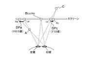
- FIG. 48 shows the relationship between the display position of the left and right images of an object (object) on the screen and the playback position of the stereoscopic image in stereoscopic image display using binocular parallax.
- object object
- FIG. 48 shows the relationship between the display position of the left and right images of an object (object) on the screen and the playback position of the stereoscopic image in stereoscopic image display using binocular parallax.
- the right and left lines of sight intersect on the screen surface. It becomes on the surface.
- the left image Lc is shifted to the left side and the right image Rc is shifted to the right side, the right and left lines of sight intersect at the back of the screen surface.
- the playback position is behind the screen.
- the viewer recognizes the perspective of the stereoscopic image using binocular parallax.
- Graphics that are superimposed and displayed on an image in a television receiver or the like are also expected to be rendered in conjunction with stereoscopic image display not only in two-dimensional space but also in three-dimensional depth.
- OSD On-Screen Display
- parallax adjustment is performed according to the perspective of each object in the image and the consistency of perspective is maintained.
- the purpose of this technology is to be able to satisfactorily control the depth of graphics superimposed on a stereoscopic image.
- An image data receiving unit for receiving a container in a predetermined format including a video stream;
- the video stream is obtained by encoding left-eye image data and right-eye image data constituting a stereoscopic image,
- disparity information on the other of one of the left eye image and the right eye image acquired corresponding to each of a predetermined number of divided areas of the picture display screen is inserted.
- An information acquisition unit that acquires the left-eye image data and right-eye image data from the video stream included in the container, and acquires disparity information for each divided region of each picture of the image data;
- the left-eye image data and right-eye image data acquired by the information acquisition unit and the disparity information are associated with each other and transmitted to an external device.
- a container of a predetermined format including a video stream is received by the image data receiving unit.
- the container may be a transport stream (MPEG-2 TS) adopted in the digital broadcasting standard.
- the container may be MP4 used for Internet distribution or the like, or a container of other formats.
- This video stream is obtained by encoding left-eye image data and right-eye image data constituting a stereoscopic image. Also, in this video stream, disparity information on the other of one of the left eye image and the right eye image acquired corresponding to each of a predetermined number of divided areas of the picture display screen is inserted for each picture of the image data. Yes.
- the information acquisition unit acquires left-eye image data and right-eye image data from the video stream included in the container, and acquires disparity information for each divided region of each picture of the image data.
- the left eye image data and right eye image data acquired by the information acquisition unit and the parallax information are associated with each other and transmitted to the external device by the transmission unit.
- the transmission unit transmits image data to an external device by a differential signal using a predetermined number of channels, and transmits the parallax information to the external device by inserting the parallax information during a blanking period of the image data.
- the transmission unit inserts disparity information into an information packet of a predetermined format arranged in the blanking period of the image data.
- the transmission unit distributes the disparity information for the plurality of pictures for each single picture, and
- the disparity information may be sequentially transmitted in units of pictures. In this case, even when the transmission band for transmitting the disparity information for each picture is small, the disparity information for each picture can be transmitted to the external device.
- the transmission unit has a first mode in which disparity information for a single picture is sequentially transmitted in units of a single picture, or a second mode in which disparity information for a plurality of pictures is sequentially transmitted in units of a plurality of pictures. , May be selectable.
- the first mode or the second mode can be selected according to the transmission band for transmitting the disparity information for each picture or the processing capability of the external device, and the transmission of the disparity information to the external device is good. Can be performed.
- identification information indicating whether the transmission is the transmission in the first mode or the transmission in the second mode is added to the disparity information.
- the external device can easily grasp whether the transmission is in the first mode or the second mode based on the identification information, and appropriately obtains the disparity information of each picture of the image data. Can be performed.
- the left-eye image data and right-eye image data acquired from the video stream included in the receiving container, and the disparity information are associated with each other and transmitted to the external device. For this reason, in the external device, it is possible to satisfactorily control the depth of the graphics superimposed and displayed on the stereoscopic image based on the parallax information.
- the transmission unit may be configured to transmit identification information indicating whether or not disparity information is transmitted to an external device in association with each picture of the image data. For example, as described above, when disparity information is inserted and transmitted in an information packet of a predetermined format arranged in a blanking period of image data, identification information indicating whether or not disparity information is transmitted is included in this information packet. Inserted. In this case, when disparity information for a plurality of pictures is transmitted in a unit of a plurality of pictures, the external device can easily determine the picture timing without disparity information transmission by this identification information, and waste of reception processing is eliminated. The load can be reduced.
- an image data processing unit that performs superimposition processing of subtitles or graphics to which parallax is added to the left eye image data and right eye image data acquired by the information acquisition unit, and an information acquisition unit
- a disparity information updating unit that updates the disparity information for each divided region of each picture of the image data acquired in step 305 according to the superimposition of the caption or graphics on the image, and the transmission unit is obtained by the image data processing unit.
- the left-eye image data and right-eye image data thus obtained may be associated with the parallax information updated by the parallax information updating unit and transmitted to an external device.
- the updated disparity information is transmitted to the external device. Based on the above, it is possible to satisfactorily control the depth of graphics superimposed and displayed on a stereoscopic image.
- a receiving unit that receives, from an external device, left-eye image data and right-eye image data constituting a stereoscopic image, and disparity information for each divided region of each picture of the image data;
- a graphics data generator for generating graphics data for displaying graphics on an image; Using the received image data and the disparity information and the generated graphics data, the graphics to be superimposed on the left eye image and the right eye image have a disparity corresponding to the display position of the graphics for each picture.
- an image data processing unit that obtains data of a left eye image on which the graphics are superimposed and data of a right eye image on which the graphics are superimposed.
- the reception unit receives left-eye image data and right-eye image data constituting a stereoscopic image, and parallax information for each divided region of each picture of the image data from an external device.
- the graphics data generating unit generates graphics data for displaying graphics on the image.
- This graphics is, for example, graphics such as OSD or application, or EPG information indicating service contents.
- the received image data and disparity information and the generated graphics data are used by the image data processing unit to obtain left eye image data and right eye image data on which graphics are superimposed.
- the disparity corresponding to the display position of the graphics is added to the graphics superimposed on the left-eye image and the right-eye image for each picture, so that the data and graphics of the left-eye image on which the graphics are superimposed are Data of the superimposed right eye image is obtained.
- the image data processing unit uses disparity information selected from disparity information of a predetermined number of divided regions corresponding to the display position of graphics, for example, optimal disparity information such as a minimum value, and gives disparity to the graphics. Is done.
- the depth control of the graphics that are superimposed and displayed on the stereoscopic image is performed based on the parallax information transmitted from the external device.
- the disparity information transmitted from the external device corresponds to each picture of the image data, and the graphics depth control can be performed with good picture (frame) accuracy.
- the disparity information of each picture sent from the external device is disparity information for each divided region of the picture display screen, and the depth control of graphics can be performed favorably according to the display position of the graphics. .
- Still another concept of this technology is A transmission unit that transmits image data to an external device using a differential signal with a predetermined number of channels,
- the transmitter is In an electronic device that inserts identification information indicating whether or not information to be referred to by the external device is included in the information packet in an information packet of a predetermined format arranged in a blanking period for each picture of the image data is there.
- image data is transmitted to an external device by a differential signal through a predetermined number of channels by the transmission unit. Then, in the transmission unit, identification information indicating whether or not information to be referred to by the external device is included in the information packet is inserted into the information packet in a predetermined format arranged in the blanking period for each picture of the image data. Is done.
- the information packet is a vendor specific info frame of HDMI (High-Definition Multimedia Interface).
- the image data is left eye image data and right eye image data constituting a stereoscopic image, and the information to be referred to is the other parallax with respect to one of the left eye image and the right eye image corresponding to the image data.
- Information is a vendor specific info frame of HDMI (High-Definition Multimedia Interface).
- identification information indicating whether or not information to be referred to by an external device is included in an information packet arranged in a blanking period for each picture of image data is inserted.
- the external device can easily determine the information packet that does not include the information to be referred to based on the identification information, and can eliminate the waste of the information extraction process from the information packet and reduce the processing load. Become.
- a receiver that receives image data from an external device by a differential signal using a predetermined number of channels, Identification information indicating whether or not information to be referred to is included in the information packet is inserted into the information packet of a predetermined format arranged in the blanking period for each picture of the image data, When the identification information indicates that information to be referred to is included in the information packet, the information to be referred to is extracted from the information packet, and the received image data is converted based on the information to be referred to.
- the electronic apparatus further includes an image data processing unit to process.
- the image data is received from the external device by a differential signal using a predetermined number of channels by the receiving unit.
- Identification information indicating whether or not information to be referred to is included in the information packet is inserted in an information packet of a predetermined format arranged in the blanking period for each picture of the image data.
- the information packet is an HDMI vendor specific info frame.
- the image data is left eye image data and right eye image data constituting a stereoscopic image, and the information to be referred to is the other parallax with respect to one of the left eye image and the right eye image corresponding to the image data.
- Information is included in the information packet.
- the image data processing unit When the image data processing unit indicates that the identification information includes information to be referred to in the information packet, the information to be referred to is extracted from the information packet, and the received image is based on the information to be referred to. Data is processed. It is possible to eliminate waste of information extraction processing from information packets and reduce processing load.
- FIG. 11 is a diagram illustrating a structure example of VS_Info when the mode is a single picture mode and the divided region is “16”.
- FIG. 10 is a diagram illustrating a structure example of VS_Info in a double picture mode when a divided region is “16”. It is a figure which shows roughly the case where a picture unit reception and single picture mode transmission are performed.
- FIG. 1 shows a configuration example of an image transmission / reception system 10 as an embodiment.
- the image transmission / reception system 10 includes a broadcasting station 100, a set top box (STB) 200, and a television receiver 300 as a monitor.
- the set top box 200 and the television receiver (TV) 300 are connected via an HDMI (High Definition Multimedia Interface) cable 400.
- HDMI High Definition Multimedia Interface
- the broadcasting station 100 transmits a transport stream TS as a container on a broadcast wave.
- This transport stream TS includes a video stream obtained by encoding left-eye image data and right-eye image data constituting a stereoscopic image.
- left eye image data and right eye image data are transmitted by one video stream.
- the left eye image data and the right eye image data are interleaved, configured as side-by-side or top-and-bottom image data, and included in one video stream.
- the left eye image data and the right eye image data are each transmitted by separate video streams.
- the left-eye image data is included in the MVC base view stream
- the right-eye image data is included in the MVC non-base view stream.
- the other disparity information (Disparity data) with respect to one of the left eye image and the right eye image acquired for each picture of the image data is inserted.
- the disparity information for each picture includes division information of the picture display screen and disparity information of each divided region (Partition).
- this disparity information is obtained as a negative value (see DPa in FIG. 48).
- this disparity information is obtained as a positive value (see DPc in FIG. 48).
- the disparity information of each divided region is acquired by performing a downsizing process on the disparity information for each block (Block).
- FIG. 2 shows an example of disparity information (disparity vector) for each block.
- FIG. 3 shows an example of a method for generating disparity information in units of blocks.
- disparity information indicating the right eye view (Right-View) is obtained from the left eye view (Left-View).
- a pixel block (parallax detection block) such as 4 * 4, 8 * 8, or 16 * 16 is set in the picture of the left eye view.
- the left-eye view picture is the detected image
- the right-eye view picture is the reference image
- the sum of absolute differences between pixels is minimized for each block of the left-eye view picture.
- a block search of the picture of the right eye view is performed to obtain disparity data.
- the parallax information DPn of the Nth block is obtained by block search so that the sum of absolute differences in the Nth block is minimized, for example, as shown in the following equation (1).
- Dj represents a pixel value in the right-eye view picture
- Di represents a pixel value in the left-eye view picture.
- DPn min ( ⁇ abs (differ (Dj-Di)) (1)
- FIG. 4 shows an example of the downsizing process.
- FIG. 4A shows disparity information for each block obtained as described above.
- disparity information for each group (Group ⁇ ⁇ Of Block) is obtained.
- a group corresponds to an upper layer of a block and is obtained by grouping a plurality of adjacent blocks together.
- each group is composed of four blocks bounded by a broken line frame. Then, the disparity vector of each group is obtained, for example, by selecting the disparity information having the minimum value from the disparity information of all blocks in the group.
- disparity information for each partition is obtained based on the disparity vector for each group.
- the partition is an upper layer of the group and is obtained by grouping a plurality of adjacent groups together.
- each partition is configured by two groups bounded by a broken line frame.
- the disparity information of each partition is obtained, for example, by selecting the disparity information having the minimum value from the disparity information of all groups in the partition.
- disparity information for the entire picture (entire image) located in the highest layer is obtained.
- the entire picture includes four partitions that are bounded by a broken line frame.
- the disparity information for the entire picture is obtained, for example, by selecting the minimum value of disparity information from the disparity information for all partitions included in the entire picture.
- the picture display screen is divided based on the division information, and the parallax information of each divided area is acquired as described above. In this case, the picture display screen is divided so as not to cross the coding block boundary.
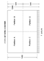
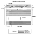
- FIG. 5 shows a detailed example of division of the picture display screen. This example is an example of a 1920 * 1080 pixel format, and is divided into two parts horizontally and vertically, and four divided regions of Partition A, Partition , B, Partition C, and Partition2D are obtained.
- On the transmission side since encoding is performed for each 16 ⁇ 16 block, 8 lines of blank data are added, and encoding is performed as image data of 1920 pixels * 1088 lines. Therefore, the vertical direction is divided into two based on 1088 lines.
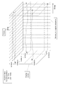
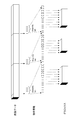
- FIG. 6 schematically shows a transition example of the parallax information of each divided region.
- This example is an example in which there are 16 divided areas from Partition 0 to 15 Partition 15 respectively, which are divided into 4 parts horizontally and vertically.
- the value of each parallax information includes a case where the value changes with time (D0, D3, D9) and a case where the value is fixed (D15).
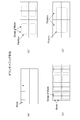
- FIG. 7A shows an example of synchronizing with picture encoding, that is, an example of inserting disparity information into a video stream in units of pictures. In this example, there is little delay when transmitting image data, and it is suitable for live broadcasting for transmitting image data captured by a camera.
- FIG. 7B shows an example of synchronizing with an I picture (Intra picture) or GOP (Group Of Pictures) of encoded video, that is, an example in which disparity information is inserted into a video stream in units of GOPs.
- I picture Intra picture
- GOP Group Of Pictures
- the delay in transmitting image data is larger than in the example of FIG. 7A.
- FIG. 7C shows an example of synchronizing with a video scene, that is, an example of inserting disparity information into a video stream in units of scenes.
- FIGS. 7A to 7C are examples, and insertion in other units may be considered.
- identification information for identifying whether or not disparity information is inserted into the video stream is inserted into the layer of the transport stream TS.
- This identification information is inserted, for example, under the program map table (PMT: Program Map Table) included in the transport stream TS or under the event information table (EIT: Event Information Table).
- PMT Program Map Table
- EIT Event Information Table
- FIG. 8 illustrates a configuration example of the transmission data generation unit 110 that generates the above-described transport stream TS in the broadcast station 100.
- the transmission data generation unit 110 includes image data output units 111L and 111R, scalers 112L and 112R, a video encoder 113, a multiplexer 114, and a parallax data generation unit 115. Further, the transmission data generation unit 110 includes a subtitle data output unit 116, a subtitle encoder 117, an audio data output unit 118, and an audio encoder 119.
- the image data output units 111L and 111R output left-eye image data VL and right-eye image data VR constituting a stereoscopic image, respectively.
- the image data output units 111L and 111R include, for example, a camera that captures an image of a subject and outputs image data, or an image data reading unit that reads and outputs image data from a storage medium.
- the image data VL and VR are, for example, 1920 * 1080 full HD size image data.
- Scalers 112L and 112R perform scaling processing in the horizontal direction and the vertical direction as necessary on the image data VL and VR, respectively. For example, when transmitting side-by-side or top-and-bottom image data in order to transmit the image data VL and VR in one video stream, the horizontal or vertical direction is 1 ⁇ 2. Scale down to output. Further, for example, when the image data VL and VR are transmitted as separate video streams such as an MVC base view stream and a non-base view stream, the image data VL and VR are not subjected to scaling processing. Is output as is.
- the video encoder 113 encodes the left-eye image data and the right-eye image data output from the scalers 112L and 112R, for example, MPEG4-AVC (MVC), MPEG2 video, or HEVC (High-Efficiency-Video Coding). To obtain encoded video data. Further, the video encoder 113 generates a video stream including the encoded data by a stream formatter (not shown) provided in the subsequent stage. In this case, the video encoder 113 generates one or two video streams (video elementary streams) including encoded video data of left eye image data and right eye image data.
- MVC MPEG4-AVC
- HEVC High-Efficiency-Video Coding
- the parallax data generation unit 115 generates parallax information for each picture (frame) based on the left eye image data VL and the right eye image data VR output from the image data output units 111L and 111R.
- the disparity data generation unit 115 acquires disparity information for each block (Block) as described above for each picture.
- the parallax data generation unit 115 reads out and acquires parallax information for each block from the storage medium together with the image data. Is also possible.
- the disparity information generation unit 115 performs a downsizing process on disparity information for each block (Block) based on, for example, the division information of the picture display screen given by a user operation, and the disparity of each divided region (Partition) Generate information.
- the video encoder 113 inserts the disparity information for each picture generated by the disparity data generation unit 115 into the video stream.
- the disparity information for each picture includes division information of the picture display screen and disparity information of each divided region.
- disparity information for each picture is inserted into the video stream in units of pictures or units of GOP (see FIG. 7). Note that the left-eye image data and the right-eye image data may be inserted only into one of the video streams in order to be transmitted as separate video data.
- the subtitle data output unit 116 outputs subtitle (caption) data to be superimposed on the image.
- the subtitle data output unit 116 is configured by, for example, a personal computer.
- the subtitle encoder 117 generates a subtitle stream (subtitle elementary stream) including the subtitle data output from the subtitle data output unit 116.
- the subtitle encoder 117 refers to the disparity information for each block generated by the disparity data generation unit 115, and adds disparity information corresponding to the display position of the subtitle to the subtitle data. That is, the subtitle data included in the subtitle stream has disparity information corresponding to the display position of the subtitle.
- the audio data output unit 118 outputs audio data corresponding to the image data.
- the audio data output unit 118 is configured by, for example, a microphone or an audio data reading unit that reads and outputs audio data from a storage medium.
- the audio encoder 119 performs encoding such as MPEG-2Audio or AAC on the audio data output from the audio data output unit 118, and generates an audio stream (audio elementary stream).
- the multiplexer 114 converts each elementary stream generated by the video encoder 113, the subtitle encoder 117, and the audio encoder 119 into PES packets and multiplexes them to generate a transport stream TS.
- PTS Presentation Time Stamp
- PES Packetized Elementary Stream
- the multiplexer 114 inserts the identification information described above into the layer of the transport stream TS.
- This identification information is information for identifying whether or not disparity information is inserted in the video stream.
- This identification information is inserted, for example, under the program map table (PMT: Program Map Table) included in the transport stream TS or under the event information table (EIT: Event Information Table).
- PMT Program Map Table
- EIT Event Information Table
- the operation of the transmission data generation unit 110 shown in FIG. 8 will be briefly described.
- the left eye image data VL and the right eye image data VR constituting the stereoscopic image output from the image data output units 111L and 111R are supplied to the scalers 112L and 112R, respectively.
- the scalers 112L and 112R horizontal and vertical scaling processes are performed on the image data VL and VR, as necessary.
- the left eye image data and right eye image data output from the scalers 112L and 112R are supplied to the video encoder 113.
- the video encoder 113 performs encoding such as MPEG4-AVC (MVC), MPEG2 video, HEVC or the like on the left eye image data and the right eye image data to obtain encoded video data. Further, in the video encoder 113, a video stream including the encoded data is generated by a stream formatter provided in the subsequent stage. In this case, one or two video streams including encoded video data of left eye image data and right eye image data are generated.
- MVC MPEG4-AVC
- MPEG2 video MPEG2 video
- HEVC High Efficiency Video Coding
- the left eye image data VL and the right eye image data VR constituting the stereoscopic image output from the image data output units 111L and 111R are supplied to the parallax data generation unit 115.
- parallax data generation unit 115 parallax information is generated for each picture (frame) based on the left eye image data VL and the right eye image data VR.
- the disparity data generating unit 115 acquires disparity information for each block (Block) for each picture.
- the disparity data generation unit 115 further performs downsizing processing on the disparity information for each block (Block) based on, for example, the division information of the picture display screen given by a user operation, so that each divided region ( Partition) disparity information is generated.
- the disparity information for each picture generated by the disparity data generation unit 115 (including the division information of the picture display screen) is supplied to the video encoder 113.
- disparity information for each picture is inserted into the video stream.
- the disparity information for each picture is inserted into the video stream in units of pictures or units of GOP.
- the subtitle data output unit 116 outputs subtitle (caption) data to be superimposed on the image.
- This subtitle data is supplied to the subtitle encoder 117.
- a subtitle stream including subtitle data is generated.
- the subtitle encoder 117 refers to the disparity information for each block generated by the disparity data generation unit 115, and disparity information corresponding to the display position is added to the subtitle data.
- the audio data output unit 118 outputs audio data corresponding to the image data.
- This audio data is supplied to the audio encoder 119.
- the audio encoder 119 performs encoding such as MPEG-2Audio or AAC on the audio data, and generates an audio stream.
- the video stream obtained by the video encoder 113, the subtitle stream obtained by the subtitle encoder 117, and the audio stream obtained by the audio encoder 119 are respectively supplied to the multiplexer 114.
- the multiplexer 114 the elementary streams supplied from each encoder are converted into PES packets and multiplexed to generate a transport stream TS. In this case, a PTS is inserted into each PES header for synchronous reproduction on the receiving side. Also, in the multiplexer 114, identification information for identifying whether or not disparity information is inserted into the video stream is inserted under the PMT or the EIT.
- FIG. 9 illustrates a configuration example of the transport stream TS.
- left eye image data and right eye image data are transmitted in separate video streams. That is, the PES packet “video PES1” of the video stream in which the left eye image data is encoded and the PES packet “video PES2” of the video stream in which the right eye image data is encoded are included. Also, in this configuration example, the subtitle stream PES packet “subtitle PES3” in which subtitle data (including disparity information) is encoded and the audio stream PES packet “audio PES4” in which audio data is encoded are included. It is.
- depth information for graphics (depth_information_for_graphics ()) including disparity information for each picture is inserted.
- this depth information for graphics is inserted into the user data area of each picture of the video stream.
- this depth information for graphics is inserted into the user data area of the first picture in the GOP of the video stream.
- the depth information for graphics is shown to be inserted into both of the two video streams, but may be inserted into only one video stream.
- the transport stream TS includes a PMT (Program Map Table) as PSI (Program Specific Information). This PSI is information describing to which program each elementary stream included in the transport stream TS belongs.
- the transport stream TS includes an EIT (Event Information Table) as SI (Serviced Information) for managing each event.
- the identification information indicating whether or not disparity information is inserted in the video stream described above is described in, for example, a descriptor inserted under the video elementary loop of the program map table.
- the descriptor is, for example, an existing AVC video descriptor (AVC video descriptor) or MVC extension descriptor (MVC_extension_descriptor), or a newly defined graphics depth info descriptor (graphics_depth_info_descriptor). Note that the graphics depth info descriptor may be inserted under the EIT as shown by the broken line.
- FIG. 10A shows a structural example (Syntax) of an AVC video descriptor (AVC video descriptor) in which identification information is described.
- AVC video descriptor AVC video descriptor
- This descriptor can be applied when the video is in the MPEG4-AVC frame compatible format.
- This descriptor itself is already H.264. H.264 / AVC standard.
- 1-bit flag information of “graphics_depth_info_not_existed_flag [0]” is newly defined in this descriptor.
- This flag information is obtained by inserting depth information for graphics (depth_information_for_graphics ()) including disparity information for each picture into the corresponding video stream, as shown in the specified content (semantics) of FIG. 10B. Indicates whether or not. When this flag information is “0”, it indicates that it is inserted. On the other hand, when this flag information is “1”, it indicates that it is not inserted.
- FIG. 11A shows a structural example (Syntax) of an MVC extension descriptor (MVC extension descriptor) in which identification information is described.
- MVC extension descriptor MVC extension descriptor
- This descriptor can be applied when the video is in the MPEG4-AVCAnex H MVC format.
- This descriptor itself is already H.264. H.264 / AVC standard.
- 1-bit flag information of “graphics_depth_info_not_existed_flag” is newly defined in this descriptor.
- This flag information is obtained by inserting depth information for graphics (depth_information_for_graphics ()) including disparity information for each picture into the corresponding video stream, as shown in the specified content (semantics) of FIG. 11B. Indicates whether or not. When this flag information is “0”, it indicates that it is inserted. On the other hand, when this flag information is “1”, it indicates that it is not inserted.
- FIG. 12A shows a structural example (Syntax) of the graphics depth info descriptor (graphics_depth_info_descriptor).
- the 8-bit field of “descriptor_tag” indicates that this descriptor is “graphics_depth_info_descriptor”.
- the 8-bit field of “descriptor_length” indicates the number of subsequent data bytes. In this descriptor, 1-bit flag information of “graphics_depth_info_not_existed_flag” is described.
- This flag information is obtained by inserting depth information for graphics (depth_information_for_graphics ()) including disparity information for each picture into the corresponding video stream, as shown in the specified content (semantics) of FIG. Indicates whether or not. When this flag information is “0”, it indicates that it is inserted. On the other hand, when this flag information is “1”, it indicates that it is not inserted.
- depth information for graphics depth_information_for_graphics ()
- disparity information for each picture is inserted into the user data area of the video stream.
- FIG. 13A shows the top access unit of a GOP (Group Of Pictures), and FIG. 13B shows an access unit other than the top of the GOP.
- depth_information_for_graphicsgraphicSEI message is inserted only in the first access unit of the GOP.
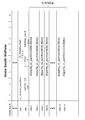
- FIG. 14A shows a structural example (Syntax) of “depth_information_for_graphics SEI message”. “Uuid_iso_iec_11578” has a UUID value indicated by “ISO / IEC 11578: 1996 Annex A.”. “Depth_information_for_graphics_data ()” is inserted in the field of “user_data_payload_byte”.
- FIG. 14B illustrates a structure example (Syntax) of “depth_information_for_graphics_data ()”. In this, depth information for graphics (depth_information_for_graphics ()) is inserted. “Userdata_id” is an identifier of “depth_information_for_graphics ()” indicated by unsigned 16 bits.
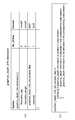
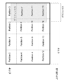
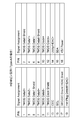
- FIG. 15 shows a structure example (Syntax) of “depth_information_for_graphics ()” when disparity information for each picture is inserted in units of pictures.
- FIG. 16 shows the contents (Semantics) of main information in the structural example shown in FIG.
- “3-bit field of“ partition_type ” indicates the partition type of the picture display screen. “000” indicates no division, “001” indicates that the horizontal and vertical are divided into two equal parts, and “010” indicates that the horizontal and vertical are divided into four equal parts.
- the 8-bit field of “disparity_in_partition” indicates representative disparity information (representative disparity value) of each partition area (Partition). In many cases, this is the minimum value of the disparity information of the corresponding area.
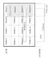
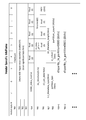
- FIG. 18 shows a structure example (Syntax) of “depth_information_for_graphics ()” when a plurality of pictures are encoded together, such as when disparity information for each picture is inserted in GOP units.
- FIG. 19 shows the contents (Semantics) of main information in the structural example shown in FIG.
- the 6-bit field “picture_count” indicates the number of pictures.
- This “depth_information_for_graphics ()” includes “disparity_in_partition” of each partition area (Partition) for the number of pictures.
- FIG. 20A illustrates a structure example (Syntax) of “user_data ()”.
- a 32-bit field of “user_data_start_code” is a start code of user data (user_data), and is a fixed value of “0x000001B2”.
- the 32-bit field following this start code is an identifier for identifying the contents of user data.
- it is “depth_information_for_graphics_data_identifier”, and it is possible to identify that the user data is “depth_information_for_graphics_data”.
- “depth_information_for_graphics_data ()” is inserted.
- FIG. 20B shows a structural example (Syntax) of “depth_information_for_graphics_data ()”. In this, “depth_information_for_graphics ()” is inserted (see FIGS. 15 and 18).
- disparity information insertion into a video stream when the encoding method is AVC or MPEG2 video has been described. Although detailed description is omitted, disparity information can be inserted into a video stream with a similar structure even in an encoding method having another similar structure, such as HEVC.
- the set top box 200 receives the transport stream TS transmitted from the broadcast station 100 on the broadcast wave. Further, the set top box 200 decodes the video stream included in the transport stream TS, and generates left eye image data and right eye image data constituting a stereoscopic image. Further, the set top box 200 extracts disparity information for each picture of the image data inserted in the video stream.
- the set-top box 200 uses the image data, the parallax information, and the graphics data to display the left-eye image data and the right-eye image data on which the graphics are superimposed. obtain.
- the set-top box 200 assigns a parallax corresponding to the display position of the graphics to the graphics superimposed on the left-eye image and the right-eye image for each picture, and data of the left-eye image on which the graphics are superimposed. And right eye image data on which graphics are superimposed.
- FIG. 21 shows the concept of graphics depth control using disparity information.
- the parallax information is a negative value
- parallax is given so that the left-eye display graphics are shifted to the right side and the right-eye display graphics are shifted to the left side on the screen.
- the graphics display position is in front of the screen.
- the parallax information is a positive value
- the parallax is given so that the left-eye display graphics are shifted to the left side and the right-eye display graphics are shifted to the right side on the screen.
- the graphics display position is behind the screen.
- the set-top box 200 can accurately control the depth of graphics using disparity information using disparity information that matches the display timing of graphics.
- FIG. 22 shows an example in which disparity information is inserted in units of pictures in the video stream.
- disparity information is sequentially acquired at the picture timing of image data.
- disparity information suitable for the display timing of graphics is used, and appropriate disparity is given to the graphics.
- FIG. 23 shows an example in which disparity information is inserted into the video stream in units of GOPs.
- Information (disparity information set) is acquired collectively.
- displaying graphics (STB graphics)
- disparity information suitable for the display timing of graphics is used, and appropriate disparity is given to the graphics.
- “Side View” in FIG. 24A shows a display example of subtitles and OSD graphics on an image.
- This display example is an example in which subtitles and graphics are superimposed on an image composed of a background, a foreground object, and a foreground object.
- “Top View” in FIG. 24B indicates the perspective of the background, the middle scene object, the foreground object, the caption, and the graphics.
- the subtitles and graphics indicate that they are recognized as being in front of the object corresponding to the display position.
- an appropriate parallax is given to the graphics so that the graphics are recognized in front of the caption.
- FIG. 25 shows a configuration example of the set top box 200.
- the set top box 200 includes a container buffer 211, a demultiplexer 212, a coded buffer 213, a video decoder 214, a decoded buffer 215, a scaler 216, and a superimposing unit 217.
- the set top box 200 includes a disparity information buffer 218, a set top box (STB) graphics generation unit 219, a depth control unit 220, and a graphics buffer 221.
- the set top box 200 also includes a coded buffer 231, a subtitle decoder 232, a pixel buffer 233, a subtitle parallax information buffer 234, and a subtitle display control unit 235.
- the set top box 200 includes a coded buffer 241, an audio decoder 242, an audio buffer 243, a channel mixing unit 244, and an HDMI transmission unit 251.
- the container buffer 211 temporarily stores a transport stream TS received by a digital tuner or the like (not shown).
- the transport stream TS includes a video stream, a subtitle stream, and an audio stream.
- As the video stream one or two video streams obtained by encoding the left eye image data and the right eye image data are included.
- left eye image data and right eye image data may be sent in separate video streams, such as an MVC base view stream and a non-base view stream, respectively.
- the demultiplexer 212 extracts video, subtitle, and audio streams from the transport stream TS temporarily stored in the container buffer 211. Further, the demultiplexer 212 extracts identification information (flag information of “graphics_depth_info_not_existed_flag”) indicating whether or not disparity information is inserted into the video stream from the transport stream TS, and sends it to a control unit (CPU) (not shown). send. Under the control of the control unit (CPU), the video decoder 214 acquires disparity information from the video stream as described later when the identification information indicates insertion of disparity information.
- the coded buffer 213 temporarily stores the video stream extracted by the demultiplexer 212.
- the video decoder 214 performs decoding processing on the video stream stored in the coded buffer 213 to obtain left eye image data and right eye image data.
- the video decoder 214 acquires disparity information for each picture of image data inserted in the video stream.
- the disparity information of each picture includes partition information of the picture display screen and disparity information (disparity) of each partition region (Partition).
- the decoded buffer 215 temporarily stores the left eye image data and right eye image data acquired by the video decoder 214.
- the disparity information buffer 218 temporarily stores disparity information for each picture of the image data acquired by the video decoder 214.
- the scaler 216 performs scaling processing in the horizontal direction and the vertical direction on the left eye image data and right eye image data output from the decoded buffer 215 as necessary. For example, when left-eye image data and right-eye image data are sent as a single video stream as side-by-side or top-and-bottom image data, the horizontal or vertical direction is doubled. Scale up to output. Also, for example, when the left-eye image data and the right-eye image data are respectively sent as separate video streams such as an MVC base view stream and a non-base view stream, without performing a scaling process, The left eye image data and right eye image data are output as they are.
- the coded buffer 231 temporarily stores the subtitle stream extracted by the demultiplexer 212.
- the subtitle decoder 232 performs a process reverse to that of the subtitle encoder 117 (see FIG. 8) of the transmission data generation unit 110 described above. That is, the subtitle decoder 232 performs a decoding process on the subtitle stream stored in the coded buffer 231 to obtain subtitle data.
- the subtitle data includes bitmap data of the subtitle (subtitle), display position information “Subtitle rendering position (x2, y2)” of the subtitle, and parallax information “Subtitle disparity” of the subtitle (subtitle). .
- the pixel buffer 233 temporarily stores the subtitle (caption) bitmap data obtained by the subtitle decoder 232 and the subtitle (caption) display position information “Subtitlexrendering position (x2, y2)”.
- the subtitle disparity information buffer 234 temporarily stores the subtitle (caption) disparity information “Subtitle disparity” obtained by the subtitle decoder 232.
- the subtitle display control unit 235 uses the subtitle (caption) bitmap data, the display position information and the parallax information of the subtitle (caption), and the subtitles for the left eye display and the right eye display to which the parallax is added. Generate bitmap data “Subtitle data”.
- the set top box (STB) graphics generation unit 219 generates graphics data such as OSD, application, or EPG. This graphics data includes graphics bitmap data “Graphics data” and display position information “Graphics rendering position (x1, y1)” of the graphics.
- the graphics buffer 221 temporarily stores the graphics bitmap data “Graphics data” generated by the set-top box graphics generation unit 219.
- the superimposing unit 217 superimposes the left eye display data and the right eye display subtitle bitmap data “Subtitle data” generated by the subtitle display control unit 235 on the left eye image data and the right eye image data, respectively.
- the superimposing unit 217 superimposes the graphics bitmap data “Graphics data” stored in the graphics buffer 221 on the left eye image data and the right eye image data, respectively.
- the graphics bitmap data “Graphics data” superimposed on each of the left eye image data and the right eye image data is given parallax by the depth control unit 220 described later.
- the superimposing unit 217 overwrites the graphics data on the subtitle data.
- the depth control unit 220 gives disparity to the graphics bitmap data “Graphics data” superimposed on each of the left eye image data and the right eye image data. Therefore, the depth control unit 220 generates graphics display position information “Rendering position” for left-eye display and right-eye display for each picture of image data, and graphics bitmap data stored in the graphics buffer 221. Shift control of the superimposition position on the left eye image data and right eye image data of “Graphics data” is performed.
- the depth control unit 220 generates display position information “Rendering position” using the following information. That is, the depth control unit 220 uses disparity information (Disparity) of each divided region (Partition) for each picture of image data stored in the disparity information buffer 218. Also, the depth control unit 220 uses the display position information “Subtitle rendering position (x2, y2)” of the subtitle (caption) stored in the pixel buffer 233.
- the depth control unit 220 uses the subtitle (subtitle) disparity information “Subtitle disparity” stored in the subtitle disparity information buffer 234. Further, the depth control unit 220 uses the display position information “Graphics rendering position (x1, y1)” generated by the set top box graphics generation unit 219. In addition, the depth control unit 220 uses identification information indicating whether or not disparity information is inserted in the video stream.
- the depth control unit 220 updates the disparity information for each divided region of each picture of the image data stored in the disparity information buffer 218 according to the superimposition of the caption or graphics on the image.
- the depth control unit 220 assigns the value of the disparity information (Disparity) of the divided region (Partition) corresponding to the display position of the subtitle (caption) and the display position of the graphics, for example, the disparity addition of the subtitle (caption) or graphics To the value of the disparity information (Disparity) used in
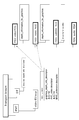
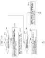
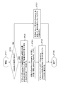
- FIGS. 27 and 28 show an example of the procedure of the control process of the depth control unit 220.
- the depth control unit 220 executes this control process for each picture (frame) that performs graphics display.
- the depth control unit 220 starts control processing in step ST1. Thereafter, in step ST2, it is determined based on the identification information whether there is insertion of disparity information for graphics in the video stream.
- step ST3 When the disparity information is inserted into the video stream, the depth control unit 220 proceeds to the process of step ST3. In this step ST3, all the divided regions (partitions) including the coordinates for overlaying (overlaying) graphics are inspected. In step ST4, the depth control unit 220 compares the disparity information (disparity) of the target divided region (partition), selects an optimum value, for example, the minimum value, and sets the value of the graphics disparity information (disparity). (Graphics_disparity).
- step ST5 the depth control unit 220 proceeds to the process of step ST5.
- the depth control unit 220 determines whether there is a subtitle stream (Subtitle stream) having disparity information (disparity).
- the depth control unit 220 determines the value (subtitle_disparity) of the subtitle disparity information (disparity) and the value of the disparity information for graphics. Compare with (graphics_disparity). Note that the value of graphics disparity information (graphics_disparity) is, for example, “0” when no graphics disparity information (disparity) is inserted into the video stream.
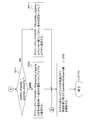
- step ST7 the depth control unit 220 determines whether or not the condition “subtitle_disparity> (graphics_disparity) is satisfied.
- the depth control unit 220 determines in step ST8 that the graphics buffer For the graphics bitmap data “Graphics data” stored in 221, for the left-eye display in which the display position is shifted by using a value equivalent to the value (graphics_disparity) of the disparity information for graphics (graphics_disparity)
- Graphics bitmap data for right-eye display is obtained and superimposed on left-eye image data and right-eye image data, respectively.
- step ST9 the depth control unit 220 updates the value of the disparity information (disparity) of the divided region (Partition) corresponding to the screen position on which the subtitle or graphics is superimposed.
- the depth control unit 220 ends the control process in step ST10 after the process in step ST9.
- the depth control unit 220 uses the subtitle disparity information (disparity) for the graphics bitmap data “Graphics data” stored in the graphics buffer 221 in step ST10. Is used to obtain graphics bitmap data for left-eye display and right-eye display whose display positions are shifted, and are superimposed on the left-eye image data and right-eye image data, respectively.
- the depth control unit 220 goes through the process of step ST9 and ends the control process in step ST10.
- step ST5 the depth control unit 220 proceeds to the process of step ST12.
- step ST12 the depth control unit 220 uses the value of graphics disparity information (graphics_disparity) obtained in step ST4 or the value of disparity information (disparity) calculated by the set top box 200, Performs graphics depth control.
- the depth control unit 220 sets the value of graphics disparity information (graphics_disparity) or the calculated value of disparity information (disparity) for graphics bitmap data “Graphics data” stored in the graphics buffer 221. In this way, graphics bitmap data for left-eye display and right-eye display whose display positions are shifted are obtained and superimposed on left-eye image data and right-eye image data, respectively.
- the depth control unit 220 finishes the control process in step ST10 after performing the process in step ST9 after the process in step ST12.
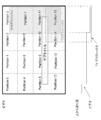
- FIG. 29 shows an example of graphics depth control in the set-top box 200.
- graphics STB graphics
- Partition 2, 3, 6, 7, 10, 11, 14, 15 Parallax is added to the left-eye display graphics and the right-eye display graphics.
- the graphics are displayed in front of the image (video) objects of these eight divided areas.
- FIG. 30 also shows an example of graphics depth control in the set-top box 200.
- graphics STB graphics
- the parallax is given to the left-eye display graphics and the right-eye display graphics.
- the graphics are displayed in front of the image (video) object of these eight divided areas and further in front of the subtitle (caption).
- the subtitle (caption) is also based on the image (video) object of the four divided regions (Partition 8, 9, 10, 11) corresponding to the display position of the subtitle based on the disparity information of the subtitle (caption). It will be displayed in the foreground.
- the disparity information update processing in the case of the depth control example in FIG. 30 is performed as follows, for example. That is, first, the disparity information (Disparity) values of the four divided regions (Partition 8, 9, 10, 11) corresponding to the display position of the subtitle are the disparity information values (subtitle_disparity) ). After that, the value of the disparity information (Disparity) of the eight divided regions (Partition2, 3, 6, 7, 10, 11, 14, 15) is updated with the disparity information value (graphics_disparity) used to add the disparity to the graphics. Is done.
- the coded buffer 241 temporarily stores the audio stream extracted by the demultiplexer 212.
- the audio decoder 242 performs processing opposite to that of the audio encoder 119 (see FIG. 8) of the transmission data generation unit 110 described above. That is, the audio decoder 242 performs decoding processing on the audio stream stored in the coded buffer 241 to obtain decoded audio data.
- the audio buffer 243 temporarily stores audio data obtained by the audio decoder 242.
- the channel mixing unit 244 generates and outputs audio data of each channel for realizing, for example, 5.1ch surround with respect to the audio data stored in the audio buffer 243.
- reading of information (data) from the decoded buffer 215, the disparity information buffer 218, the pixel buffer 233, the subtitle disparity information buffer 234, and the audio buffer 243 is performed based on the PTS, and transfer synchronization is taken.
- the HDMI transmission unit 251 transmits the left-eye image data and the right-eye image data obtained by performing the subtitle and graphics superimposition processing in the superimposition unit 217 and the channels obtained in the channel mixing unit 244 by communication conforming to HDMI.
- the HDMI sink device which is the television receiver 300 in this embodiment.
- the left eye image data obtained by the superimposing unit 217 is data of a left eye image on which a subtitle (caption) for displaying the left eye and STB graphics are superimposed.
- the right eye image data obtained by the superimposing unit 217 is data of a right eye image on which a subtitle (caption) for displaying the right eye and STB graphics are superimposed.
- the HDMI transmission unit 251 transmits the disparity information (Disparity) for each divided region of each picture of the image data updated by the depth control unit 220 to the television receiver 300 through the HDMI interface.
- the disparity information is inserted and transmitted during the blanking period of the image data. Details of the HDMI transmission unit 251 will be described later.
- the transport stream TS received by a digital tuner or the like is temporarily stored in the container buffer 211.
- the transport stream TS includes a video stream, a subtitle stream, and an audio stream.
- the video stream includes one or two video streams obtained by encoding the left eye image data and the right eye image data.
- the demultiplexer 212 extracts video, subtitle, and audio streams from the transport stream TS temporarily stored in the container buffer 211. Further, the demultiplexer 212 extracts identification information (flag information of “graphics_depth_info_not_existed_flag”) indicating whether or not disparity information is inserted in the video stream from the transport stream TS, and sends it to a control unit (CPU) (not shown). Sent.
- the video stream extracted by the demultiplexer 212 is supplied to the coded buffer 213 and temporarily stored.
- the video decoder 214 then decodes the video stream stored in the coded buffer 213 to obtain left eye image data and right eye image data.
- the left eye image data and right eye image data are temporarily stored in the decoded buffer 215.
- the video decoder 214 acquires disparity information for each picture of the image data inserted in the video stream. This disparity information is temporarily stored in the disparity information buffer 218.
- the scaler 216 performs horizontal and vertical scaling processing on the left eye image data and right eye image data output from the decoded buffer 215 as necessary. From this scaler 216, for example, left-eye image data and right-eye image data having a full HD size of 1920 * 1080 are obtained. The left eye image data and right eye image data are supplied to the superimposing unit 217.
- the subtitle stream extracted by the demultiplexer 212 is supplied to the coded buffer 231 and temporarily stored.
- the subtitle decoder 232 decodes the subtitle stream stored in the coded buffer 231 to obtain subtitle data.
- the subtitle data includes bitmap data of the subtitle (subtitle), display position information “Subtitle rendering position (x2, y2)” of the subtitle, and parallax information “Subtitle disparity” of the subtitle (subtitle). .
- the subtitle (caption) bitmap data obtained by the subtitle decoder 232 and the subtitle (caption) display position information “Subtitlexrendering position (x2, y2)” are temporarily stored in the pixel buffer 233. Also, the subtitle disparity information “Subtitle disparity” obtained by the subtitle decoder 232 is temporarily stored in the subtitle disparity information buffer 234.
- the subtitle display control unit 235 uses the subtitle (caption) bitmap data, the display position information and the parallax information of the subtitle (caption), and the subtitles for the left eye display and the right eye display to which the parallax is added.
- Bitmap data “Subtitle data” is generated.
- the left-eye display and right-eye display subtitle bitmap data “Subtitle ⁇ data” generated in this way is supplied to the superimposing unit 217 and is superimposed on the left-eye image data and the right-eye image data, respectively.
- the set top box (STB) graphics generation unit 219 generates graphics data such as OSD, application, or EPG.
- the graphics data includes graphics bitmap data “Graphics data” and display position information “Graphics rendering position (x1, y1)” of the graphics.
- the graphics buffer 221 temporarily stores graphics data generated by the set top box (STB) graphics generation unit 219.
- the graphics bitmap data “Graphics data” stored in the graphics buffer 221 is superimposed on the left eye image data and the right eye image data.
- the graphics bitmap data “Graphics data” superimposed on each of the left-eye image data and the right-eye image data is given disparity by the depth control unit 220 based on disparity information corresponding to the display position of the graphics. Is done.
- the superimposing unit 217 overwrites the graphics data on the subtitle data.
- the superimposing unit 217 obtains left-eye image data in which the left-eye display subtitle (caption) and STB graphics are superimposed, and the right-eye display subtitle (caption) and STB graphics are superimposed on the right eye. Image data is obtained.
- the left eye image data and right eye image data are supplied to the HDMI transmission unit 251.
- the audio stream extracted by the demultiplexer 212 is supplied to the coded buffer 241 and temporarily stored.
- the audio decoder 242 decodes the audio stream stored in the coded buffer 241 to obtain decoded audio data.
- This audio data is supplied to the channel mixing unit 244 via the audio buffer 243.
- the channel mixing unit 244 generates audio data for each channel for realizing, for example, 5.1ch surround with respect to the audio data.
- the audio data is supplied to the HDMI transmission unit 251.
- the disparity information for each divided region of each picture of the image data stored in the disparity information buffer 218 is updated according to the superimposition of the caption or graphics on the image.
- the value of the disparity information (Disparity) of the divided region (Partition) corresponding to the display position of the subtitle (caption) and the display position of the graphics is, for example, the disparity information used to add the disparity of the subtitle (caption) or graphics. Updated to (Disparity) value.
- the updated parallax information is supplied to the HDMI transmission unit 251.
- the HDMI transmission unit 251 left-eye image data, right-eye image data, audio data, and further, disparity information (Disparity) for each divided region of each picture of the image data is transmitted to the television receiver 300 through HDMI-compliant communication.
- the disparity information is transmitted by being inserted into an information packet arranged in the blanking period of the image data, in this embodiment, an HDMI vendor specific info frame (HDMI-Vendor-Specific InfoFrame).
- the television receiver 300 divides each picture of left-eye image data, right-eye image data, audio data, and image data sent from the set-top box 200 via the HDMI cable 400. Each piece of disparity information (Disparity) is received.
- Disarity disparity information
- the television receiver 300 uses the image data, the parallax information, and the graphics data to display the left-eye image data and the right-eye image data on which the graphics are superimposed. obtain.
- the television receiver 300 assigns, for each picture, a parallax corresponding to the display position of the graphics to the graphics superimposed on the left-eye image and the right-eye image, and data of the left-eye image on which the graphics are superimposed. And right eye image data on which graphics are superimposed.
- FIG. 31 illustrates a configuration example of the HDMI input system of the television receiver 300.
- the television receiver 300 includes an HDMI receiving unit 311, a scaler 312, a superimposing unit 313, a depth control unit 314, a graphics buffer 315, a television (TV) graphics generation unit 316, and an audio processing unit 317.
- the HDMI receiving unit 311 receives audio data from left eye image data and right eye image data constituting a stereoscopic image from an HDMI source device, in this embodiment, the set top box 200, through communication conforming to HDMI. . Further, the HDMI receiving unit 311 receives disparity information (Disparity) for each divided region of each picture of the image data from the set top box 200 via the HDMI interface. Details of the HDMI receiving unit 311 will be described later.
- the scaler 312 performs a scaling process on the left eye image data and the right eye image data received by the HDMI receiving unit 311 as necessary. For example, the scaler 312 matches the size of the left eye image data and right eye image data with the display size.
- a television (TV) graphics generation unit 316 generates graphics data such as an OSD, an application, or an EPG. This graphics data includes graphics bitmap data “Graphics data” and display position information “Graphics rendering position (x1, y1)” of the graphics.
- the graphics buffer 315 temporarily stores graphics bitmap data “Graphics data” generated by the television graphics generation unit 316.
- the superimposing unit 313 superimposes graphics bitmap data “Graphics data” stored in the graphics buffer 315 on the left-eye image data and the right-eye image data, respectively.
- the graphics bitmap data “Graphics data” superimposed on each of the left eye image data and the right eye image data is given parallax by the depth control unit 314 described later.
- the depth control unit 314 gives disparity to the graphics bitmap data “Graphics data” superimposed on each of the left eye image data and the right eye image data. Therefore, the depth control unit 314 generates the display position information “Rendering position” of the left-eye display and right-eye display graphics for each picture of the image data, and the graphics bitmap data stored in the graphics buffer 315 Shift control of the superimposition position on the left eye image data and right eye image data of “Graphics data” is performed.
- the depth control unit 314 generates display position information “Rendering position” using the following information as illustrated in FIG. 32. That is, the depth control unit 314 uses the disparity information (Disparity) of each divided region (Partition) for each picture of the image data received by the HDMI receiving unit 311. Further, the depth control unit 314 uses the display position information “Graphics rendering position (x1, y1)” generated by the television graphics generation unit 316. Further, the depth control unit 314 uses reception information indicating whether or not the parallax information is received by the HDMI reception unit 311.
- step ST21 the depth control unit 314 starts control processing.
- step ST22 based on the received information, the HDMI receiving unit 311 determines whether or not there is reception of the disparity information for graphics.
- the HDMI receiving unit 311 extracts the disparity information from the packet and uses it when the identification information of “PRTY” of the HDMI Vendor Specific InfoFrame packet described later indicates the presence of disparity information as information to be referred to. Prepare. In this case, the received information is “received”.
- step ST23 When receiving disparity information (disparity), the depth control unit 314 proceeds to the process of step ST23.
- step ST23 all the divided regions (partitions) including the coordinates for overlaying (overlaying) graphics are inspected.
- step ST24 the depth control unit 314 compares the disparity information (disparity) of the target divided region (partition), selects an optimum value, for example, the minimum value, and sets the value of the graphics disparity information (disparity). (Graphics_disparity).
- the depth control unit 314 has a value equivalent to the value (graphics_disparity) of the graphics disparity information (disparity) for the graphics bitmap data “Graphics data” stored in the graphics buffer 315. Is used to obtain graphics bitmap data for left-eye display and right-eye display whose display positions are shifted, and are superimposed on left-eye image data and right-eye image data, respectively.
- the depth control unit 314 ends the control process in step ST26 after the process in step ST25.
- the depth control unit 314 When no disparity information (disparity) is received in step ST22, the depth control unit 314 performs the television receiver 300 on the graphics bitmap data “Graphics data” stored in the graphics buffer 315 in step ST27. Is used to obtain graphics bitmap data for left-eye display and right-eye display whose display positions are shifted, and the left-eye image data and right-eye image data, respectively. Superimpose on.
- the depth control unit 314 ends the control process in step ST26 after the process in step ST27.
- FIG. 34 shows an example of graphics depth control in the television receiver 300.
- graphics for left-eye display and right-eye display are based on disparity information of the minimum value among the disparity information of the four right-side divided regions (Partitions 10, 11, 14, and 15). Parallax is added to the graphics for use.
- the TV graphics is displayed in front of the image (video) objects of these four divided areas.
- the subtitle (caption) and STB graphics are already superimposed on the image (video) in the set top box 200.
- the HDMI receiving unit 311 left-eye image data, right-eye image data, audio data, and further, disparity information (Disparity) for each divided region of each picture of the image data is set by the set-top box 200. Received from.
- the left eye image data and right eye image data received by the HDMI receiving unit 311 are supplied to the superimposing unit 313 after being scaled as necessary by the scaler 312.
- the television TV) graphics generator 316 generates graphics data such as an OSD or application, or an EPG.
- the graphics data includes graphics bitmap data “Graphics data” and display position information “Graphics rendering position (x1, y1)” of the graphics.
- the graphics buffer 315 the graphics data generated by the television graphics generation unit 315 is temporarily stored.
- the graphics bitmap data “Graphics data” stored in the graphics buffer 315 is superimposed on the left eye image data and the right eye image data.
- the graphics bitmap data “Graphics data” superimposed on each of the left eye image data and the right eye image data is given disparity by the depth control unit 314 based on the disparity information corresponding to the display position of the graphics. Is done.
- the TV graphics generation unit 316 generates the disparity information (Disparity) of each divided region (Partition) for each picture of the image data received by the HDMI reception unit 311.
- Graphics display position information “Graphics rendering position (x1, y1)” is used.
- the superimposing unit 313 obtains left-eye image data on which left-eye display TV graphics are superimposed, and right-eye image data on which right-eye display TV graphics are superimposed. These image data are sent to a processing unit for stereoscopic image display, and stereoscopic image display is performed.
- the audio data of each channel received by the HDMI receiving unit 311 is supplied to the speaker via the audio processing unit 317 that adjusts the sound quality and volume, and the audio is output in accordance with the stereoscopic image display.
- FIG. 35 illustrates a configuration example of the HDMI transmission unit 251 of the set-top box 200 and the HDMI reception unit 311 of the television receiver 300 in the image transmission / reception system 10 of FIG.
- the HDMI transmission unit 251 transmits a differential signal corresponding to pixel data of an uncompressed image for one screen in an effective image section (hereinafter, also referred to as an active video section as appropriate) using a plurality of channels.
- the effective image section is a section obtained by removing the horizontal blanking section and the vertical blanking section from the section from one vertical synchronization signal to the next vertical synchronization signal.
- the HDMI transmission unit 251 receives a differential signal corresponding to at least audio data, control data, and other auxiliary data associated with an image on a plurality of channels in a horizontal blanking interval or a vertical blanking interval. Transmit to the unit 311 in one direction.
- the transmission channels of the HDMI system including the HDMI transmission unit 251 and the HDMI reception unit 311 include the following transmission channels. That is, three TMDS channels # 0 to ## as transmission channels for serially transmitting pixel data and audio data in one direction in synchronization with the pixel clock from the HDMI transmitting unit 251 to the HDMI receiving unit 311. There are two. There is also a TMDS clock channel as a transmission channel for transmitting a pixel clock.
- the HDMI transmission unit 251 has an HDMI transmitter 81.
- the transmitter 81 converts, for example, pixel data of an uncompressed image into a corresponding differential signal, and is connected via the HDMI cable 400 with three TMDS channels # 0, # 1, and # 2 that are a plurality of channels. Serial transmission in one direction to the HDMI receiving unit 311.
- the transmitter 81 converts audio data accompanying uncompressed images, further necessary control data and other auxiliary data, etc. into corresponding differential signals, and converts them into three TMDS channels # 0, # 1, #. 2 serially transmits to the HDMI receiving unit 311 in one direction.
- the transmitter 81 transmits the pixel clock synchronized with the pixel data transmitted through the three TMDS channels # 0, # 1, and # 2 to the HDMI receiving unit 311 connected via the HDMI cable 400 using the TMDS clock channel. Send.
- the HDMI receiving unit 311 receives a differential signal corresponding to pixel data transmitted in one direction from the HDMI transmitting unit 251 through a plurality of channels in the active video section. Further, the HDMI receiving unit 311 receives differential signals corresponding to audio data and control data transmitted in one direction from the HDMI transmitting unit 251 through a plurality of channels in a horizontal blanking interval or a vertical blanking interval. Receive.
- the HDMI receiving unit 311 has an HDMI receiver 82.
- This HDMI receiver 82 uses TMDS channels # 0, # 1, and # 2 to transmit a differential signal corresponding to pixel data and a difference corresponding to audio data and control data transmitted from the HDMI transmission unit 251 in one direction. Receive a motion signal. In this case, reception is performed in synchronization with the pixel clock transmitted from the HDMI transmission unit 251 through the TMDS clock channel.
- the transmission channels of the HDMI system include transmission channels called DDC (Display Data Channel) 83 and CEC line 84 in addition to the above-described TMDS channels # 0 to # 2 and the TMDS clock channel.
- the DDC 83 includes two signal lines (not shown) included in the HDMI cable 400.
- the DDC 83 is used by the HDMI transmission unit 251 to read E-EDID (Enhanced Extended Display Identification Data) from the HDMI reception unit 311.
- E-EDID Enhanced Extended Display Identification Data
- the HDMI receiving unit 311 has an EDID ROM (Read Only Memory) 85 that stores E-EDID, which is performance information related to its performance (Configuration / capability), in addition to the HDMI receiver 81.
- E-EDID ROM Read Only Memory
- the HDMI transmission unit 251 reads E-EDID from the HDMI reception unit 311 connected via the HDMI cable 400 via the DDC 83.
- the HDMI transmission unit 251 sends the read E-EDID to the control unit (CPU).
- the control unit (CPU) can recognize the performance setting of the HDMI receiving unit 311 based on the E-EDID. For example, the control unit (CPU) determines whether the television receiver 300 having the HDMI receiving unit 311 can handle stereoscopic image data, and if so, what TMDS transmission data structure can be supported. recognize.
- the CEC line 84 is made up of one signal line (not shown) included in the HDMI cable 400, and is used for bidirectional communication of control data between the HDMI transmission unit 251 and the HDMI reception unit 311.
- the CEC line 84 constitutes a control data line.
- the HDMI cable 400 includes a line (HPD line) 86 connected to a pin called HPD (Hot Plug Detect).
- HPD line 86 is also used as a HEAC-line constituting a bidirectional communication path.
- the HDMI cable 400 includes a line (power line) 87 used for supplying power from the source device to the sink device.
- the HDMI cable 400 includes a utility line 88.
- the utility line 88 is also used as a HEAC + line constituting a bidirectional communication path.
- FIG. 36 shows an example of the structure of TMDS transmission data.
- FIG. 36 shows sections of various transmission data when image data of horizontal ⁇ vertical 1920 pixels ⁇ 1080 lines is transmitted in TMDS channels # 0, # 1, and # 2.
- Video Field In a video field (Video Field) in which transmission data is transmitted through the three TMDS channels # 0, # 1, and # 2 of HDMI, there are three types of sections according to the type of transmission data. These three types of sections are a video data period (Video Data period), a data island period (Data Island period), and a control period (Control period).
- the video field period is a period from the rising edge (active edge) of a certain vertical synchronizing signal to the rising edge of the next vertical synchronizing signal.
- This video field section is divided into a horizontal blanking period (horizontal blanking), a vertical blanking period (vertical blanking), and an active video section (Active Video).
- This active video section is a section obtained by removing the horizontal blanking period and the vertical blanking period from the video field section.
- the video data section is assigned to the active video section.
- 1920 pixels (pixels) ⁇ 1080 lines of effective pixel (Active pixel) data constituting uncompressed image data for one screen is transmitted.
- Data island section and control section are assigned to horizontal blanking period and vertical blanking period.
- auxiliary data (Auxiliary data) is transmitted. That is, the data island period is assigned to a part of the horizontal blanking period and the vertical blanking period.
- audio data packets which are data not related to control, of auxiliary data are transmitted.
- the control section is assigned to other parts of the horizontal blanking period and the vertical blanking period.
- this control period for example, vertical synchronization signals, horizontal synchronization signals, control packets, and the like, which are data related to control, of auxiliary data are transmitted.
- FIG. 37 shows an example of the pin arrangement of the HDMI terminal.
- the pin arrangement shown in FIG. 37 is called type A (type-A).
- TMDS Data # i + and TMDS Data # i ⁇ which are differential signals of TMDS channel #i, are transmitted by two lines which are differential lines. These two lines consist of pins assigned TMDS Data # i + (pin numbers 1, 4, and 7) and pins assigned TMDS Data # i- (pin numbers 3, 6, and 7). 9 pin).
- the CEC line 84 through which the CEC signal, which is control data, is transmitted is connected to a pin whose pin number is 13.
- a line for transmitting an SDA (Serial Data) signal such as E-EDID is connected to a pin having a pin number of 16.
- a line through which an SCL (Serial Clock) signal, which is a clock signal used for synchronization during transmission and reception of the SDA signal, is connected to a pin having a pin number of 15.
- the above-described DDC 83 includes a line for transmitting the SDA signal and a line for transmitting the SCL signal.
- the HPD line (HEAC-line) 86 for the source device to detect the connection of the sink device is connected to a pin having a pin number of 19.
- the utility line (HEAC + line) 88 is connected to a pin having a pin number of 14.
- the line 87 for supplying power is connected to a pin having a pin number of 18.
- “3D_Metadata_type” is defined as unused, for example, “001”, and disparity information (Disparity) of each divided region (Partition) is designated.
- FIG. 38 shows an example of the packet structure of HDMI “Vendor” Specific “InfoFrame”. Since this HDMI Vendor Specific InfoFrame is defined in CEA-861-D, detailed description is omitted.
- FIG. 39 shows the contents of main information in the packet structure example shown in FIG.
- 3 bits information “HDMI_Video_Format” indicating the type of image data is arranged from the 7th bit to the 5th bit of the 4th byte (PB4).
- the 3-bit information is “010”.
- 4-bit information “3D_Structure” indicating the TMDS transmission data structure is arranged from the 7th bit to the 4th bit of the 5th byte (PB5). For example, in the case of the frame packing method, this 4-bit information is “0000”.
- 3D_Meta_present is arranged in the third bit of the fifth byte (PB5) and Vendor Specific InfoFrame extension is specified, this one bit is set to “1”. Further, “3D_Metadata_type” is arranged from the 7th bit to the 5th bit of the 7th byte (PB7). When disparity information (Disparity) of each divided region (Partition) is designated, this 3-bit information is unused, for example, “001”.
- 3D_Metadata_length is arranged from the 4th byte to the 0th byte of the 7th byte (PB7).
- This 5-bit information indicates the size of disparity information (Disparity) of each divided region (Partition).
- the value of “3D_Metadata_length” takes a value of 0x00 to 0x1F, and the value obtained by adding 2 represents the overall size of the disparity information (Disparity) after this field. For example, “00000” represents 2 (in decimal), and “11111” represents 33 (in decimal).
- 1-bit identification information of “PRTY” is arranged in the 0th bit of the 6th byte (PB6). This identification information indicates whether or not the information to be referred to by the HDMI sink side, here, disparity information (Disparity) is included in this VS_Info. “1” indicates that information to be referred to by the HDMI sink is necessarily included. “0” indicates that the information to be referred to by the HDMI sink is not necessarily included.
- the television receiver 300 in this embodiment refers to the VS_Info IV without checking “3D_Metadata_type” or less. Whether or not information to be included is included can be determined. Therefore, in the HDMI sink, extraction processing of information to be referred to from VS_Info can be performed without waste using this identification information, and the processing load can be reduced.
- partition_type is arranged from the seventh bit to the fifth bit of the eighth byte (PB8).
- This 3-bit information indicates the division type of the display screen of the target picture. “000” indicates no division, “001” indicates that the horizontal and vertical are divided into two equal parts, and “010” indicates that the horizontal and vertical are divided into four equal parts.
- 1-bit identification information of “d_picture” is arranged in the fourth bit of the eighth byte (PB8). This identification information indicates whether it is a single picture or a double picture. “0” indicates a single picture, that is, a mode for transmitting one picture as disparity information (Disparity) of each divided region (Partition). “1” indicates a double picture, that is, a mode in which two pictures are transmitted as disparity information (Disparity) of each divided region (Partition).
- Partition_count is arranged from the 3rd bit to the 0th bit of the 8th byte (PB8).
- This 4-bit information indicates the total number of partition areas (Partitions), and is a value dependent on the above-mentioned “partition_type”. For example, “0000” indicates the total number “1”, and “1111” indicates the total number “16”.
- disparity information (Disparity) of each divided region (Partition) for one picture or two pictures is sequentially arranged. That is, the 8-bit information “disparity_in_partition” indicates representative disparity information (representative disparity value) of each partition area (Partition).
- the set-top box 200 acquires disparity information for one picture at the timing of each picture in the image data (see FIG. 22). Further, as described above, when the disparity information is inserted into the video stream in units of GOPs, the set top box 200 disparity information (disparity information set) of each picture in the GOP at the start timing of the GOP of the image data. Are collectively acquired (see FIG. 23).
- the set-top box 200 is either a single picture or a double picture based on, for example, negotiation with the television receiver 300 using the CEC line 84 or setting in the EDIDROM 85. Any mode can be selected. In this case, the set-top box 200 can select a mode according to the transmission band for transmitting disparity information for each picture, the processing capability of the set-top box 200 or the television receiver 300, and the like. It becomes possible to transmit the disparity information to the satisfactorily.
- FIG. 42 illustrates a case where the set-top box 200 acquires disparity information for one picture at the timing of each picture in the image data, and sequentially transmits the disparity information for each picture to the television receiver 300 in the single picture mode.
- the set-top box 200 acquires disparity information for one picture at the timing of each picture of the image data, and sequentially transmits the disparity information of each picture to the television receiver 300 in the double picture mode.
- the case is shown schematically.
- the set top box 200 collectively acquires disparity information of each picture in the GOP at the start timing of the GOP of the image data, and the television receiver 300 uses the single picture mode to acquire each picture.
- the case where parallax information is transmitted sequentially is schematically shown.
- FIG. 45 shows that the set top box 200 collectively acquires disparity information of each picture in the GOP at the start timing of the GOP of the image data, and the television receiver 300 uses the double picture mode to acquire each picture.
- the case where parallax information is transmitted sequentially is schematically shown.
- the set-top box 200 has been described so that it can arbitrarily select a single picture mode or a double picture mode.
- the disparity information of each picture in the GOP when acquired collectively at the start timing of the GOP of the image data, it may be transmitted in the single picture mode.
- the disparity information of each picture in the GOP is distributed for each single picture, and the disparity information for each single picture is sequentially transmitted in units of pictures (see FIG. 44).
- the transmission band for transmitting the disparity information for each picture is small, the disparity information of each picture can be transmitted to the television receiver 300 satisfactorily.
- the set top box 200 can select a single picture mode or a double picture mode.
- the mode of a plurality of pictures is used instead of the mode of double pictures, and the number of pictures can be arbitrarily selected.
- the number of modes that can be selected is three or more is also conceivable. In that case, the number of partitions can be changed to an appropriate number on the HDMI source side so that transmission can be performed in a given band.
- the set-top box 200 includes the left-eye image data and right-eye image data acquired from the video stream included in the transport stream TS, disparity information, Are associated with each other and transmitted to the television receiver 300 as a monitor through the HDMI interface. Therefore, in the television receiver 300, it is possible to satisfactorily control the depth of graphics that are superimposed and displayed on a stereoscopic image based on the parallax information.
- the set-top box 200 updates the received disparity information when the superimposition processing is performed on the subtitle (caption) to which the parallax is added and the graphics image. Then, the updated parallax information is transmitted to the television receiver 300 as a monitor. Therefore, in the television receiver 300, even when the subtitle (caption) and graphics images that are given parallax in the set-top box 200 are superimposed on the images, a stereoscopic image is converted based on the parallax information. It is possible to satisfactorily control the depth of graphics that are displayed in a superimposed manner.
- the television receiver 300 as a monitor performs depth control of graphics superimposed on a stereoscopic image based on parallax information transmitted from the set top box 200.
- the disparity information sent from the set top box 200 corresponds to each picture of the image data, and the depth control of graphics can be performed with good picture (frame) accuracy.
- the disparity information of each picture sent from the set-top box 200 is disparity information for each divided region of the picture display screen, and the graphics depth control is favorably performed according to the display position of the graphics. Can do.
- the image transmission / reception system 10 includes the broadcasting station 100, the set-top box 200, and the television receiver 300.
- an image transmission / reception system 10A including a broadcasting station 100 and a television receiver 300A is also conceivable.
- FIG. 47 shows a configuration example of the television receiver 300A.
- the television (TV) graphics generation unit 219A is the same as the set top box (STB) graphics generation unit 219 of the set top box 200 of FIG. 25, and generates graphics data such as OSD, application, or EPG.
- the superimposing unit 217 obtains left-eye image data on which the left-eye display subtitle (caption) and graphics are superimposed, and the right-eye display subtitle (caption) and graphics on the right-eye image on which graphics are superimposed. Data is obtained. These image data are sent to a processing unit for stereoscopic image display, and stereoscopic image display is performed. Also, the channel mixing unit 244 generates audio data for each channel for realizing, for example, 5.1ch surround with respect to the audio data. This audio data is supplied to, for example, a speaker, and audio output is performed in accordance with the stereoscopic image display.
- the rest of the television receiver 300A shown in FIG. 47 is configured in the same manner as the set-top box 200 in FIG. 25 and operates in the same manner.
- the set-top box 200 and the television receiver 300 are connected by an HDMI digital interface.
- the present technology can be similarly applied even when these are connected by a digital interface similar to the HDMI digital interface (including wireless as well as wired).
- a method of using HDMI “Vendor” specific “InfoFrame” has been described as a method of transmitting disparity information from the set-top box 200 to the television receiver 300.
- a method using an active space (Active Space), and transmission through a bidirectional communication path composed of an HPD line 86 (HEAC ⁇ line) and a utility line 88 (HEAC + line) may be considered.
- the source device may be a disc player such as a BD or a DVD, or a game machine
- the sink device may be a monitor device or a projector device.
- the container is a transport stream (MPEG-2 TS)
- MPEG-2 TS transport stream
- the present technology can be similarly applied to a system configured to be distributed to receiving terminals using a network such as the Internet.
- the Internet distribution it is often distributed in a container of MP4 or other formats.
- containers of various formats such as transport stream (MPEG-2 TS) adopted in the digital broadcasting standard and MP4 used in Internet distribution correspond to the container.
- MPEG-2 TS transport stream
- MP4 used in Internet distribution
- a method for supplying one service content is divided into a plurality of parts and each is performed in a different transmission form, that is, one view is transmission by radio waves, and the other view ( This is also the case when view) is transmission over the Internet.
- This technique can also take the following structures.
- An image data receiving unit that receives a container of a predetermined format including a video stream, The video stream is obtained by encoding left-eye image data and right-eye image data constituting a stereoscopic image, In the video stream, for each picture of the image data, disparity information on the other of one of the left eye image and the right eye image acquired corresponding to each of a predetermined number of divided areas of the picture display screen is inserted.
- An information acquisition unit that acquires the left-eye image data and right-eye image data from the video stream included in the container, and acquires disparity information for each divided region of each picture of the image data;
- a receiving apparatus comprising: a transmission unit that associates the left-eye image data and right-eye image data acquired by the information acquisition unit with the parallax information and transmits the information to an external device.
- the transmission unit When the information acquisition unit acquires disparity information for a plurality of pictures for each unit of a plurality of pictures, The receiving device according to (1), wherein the disparity information for the plurality of pictures is distributed for each single picture, and the disparity information for each single picture is sequentially transmitted in units of pictures.
- the transmission unit has a first mode in which disparity information for a single picture is sequentially transmitted in units of a single picture, or a second mode in which disparity information for a plurality of pictures is sequentially transmitted in units of a plurality of pictures.
- the receiving device according to (1), wherein the receiving device is selectable.
- the disparity information transmitted by the transmitter is added with identification information indicating whether the transmission is in the first mode or the transmission in the second mode.
- Receiver (5)
- the transmission unit transmits identification information indicating whether or not disparity information is transmitted in association with each picture of the image data to the external device. Receiver device.
- An image data processing unit that performs a superimposition process of subtitles or graphics to which parallax is added to the left eye image data and right eye image data acquired by the information acquisition unit;
- a disparity information updating unit that updates the disparity information for each divided region of each picture of the image data acquired by the information acquisition unit according to the superimposition of the subtitles or graphics on the image;
- the transmission unit associates the left-eye image data and right-eye image data obtained by the image data processing unit with the parallax information updated by the parallax information update unit, and transmits the association to the external device.
- the receiving device according to any one of (1) to (5).
- the image data processing unit The reception according to (6), wherein disparity information is given to the graphics using disparity information selected from disparity information of a predetermined number of divided regions corresponding to the display positions of the graphics acquired by the information acquisition unit. apparatus.
- the transmission unit The image data is transmitted to the external device by a differential signal using a predetermined number of channels, The receiving device according to any one of (1) to (7), wherein the disparity information is transmitted to the external device by inserting the disparity information during a blanking period of the image data.
- the transmission unit The receiving device according to (8), wherein the disparity information is inserted into an information packet having a predetermined format arranged in a blanking period of the image data.
- (10) comprising an image data receiving step of receiving a container of a predetermined format including a video stream;
- the video stream is obtained by encoding left-eye image data and right-eye image data constituting a stereoscopic image,
- disparity information on the other of one of the left eye image and the right eye image acquired corresponding to each of a predetermined number of divided areas of the picture display screen is inserted.
- a receiving method comprising: a transmitting step of transmitting the acquired left eye image data and right eye image data, and the parallax information to an external device.
- a receiving unit that receives, from an external device, left-eye image data and right-eye image data constituting a stereoscopic image, and disparity information for each divided region of each picture of the image data;
- a graphics data generator for generating graphics data for displaying graphics on an image; Using the received image data and the disparity information and the generated graphics data, the graphics to be superimposed on the left eye image and the right eye image have a disparity corresponding to the display position of the graphics for each picture.
- a receiving apparatus comprising: an image data processing unit that provides left eye image data on which the graphics are superimposed and right eye image data on which the graphics are superimposed.
- the image data processing unit The receiving device according to (11), wherein disparity information is given to the graphics using disparity information selected from disparity information of a predetermined number of divided regions corresponding to the graphics display position.
- a receiving method comprising: an image data processing step for providing data of a left eye image on which the graphics are superimposed and data on a right eye image on which the graphics are superimposed.
- a transmission unit that transmits the image data to an external device using a differential signal through a predetermined number of channels,
- the transmitter is An electronic device that inserts identification information indicating whether or not information to be referred to by the external device is included in an information packet in an information packet of a predetermined format arranged in a blanking period for each picture of the image data.
- the image data is left eye image data and right eye image data constituting a stereoscopic image
- the electronic device according to (14), wherein the information to be referred to is parallax information of the other of the left eye image and the right eye image corresponding to the image data.
- Identification information indicating whether or not information to be referred to is included in the information packet is inserted into the information packet of a predetermined format arranged in the blanking period for each picture of the image data, When the identification information indicates that information to be referred to is included in the information packet, the information to be referred to is extracted from the information packet, and the received image data is converted based on the information to be referred to.
- An electronic device further comprising an image data processing unit for processing.
- the main feature of the present technology is that the left-eye image data and right-eye image data acquired from the video stream included in the transport stream are associated with the disparity information for each divided region of each picture, and the HDMI interface
- the monitor television receiver
- Coded buffer 232 ... Subtitle decoder 233 ... Pixel buffer 234 ... Subtitle parallax information buffer 235 ... Subtitle Display control unit 241 ; Coded buffer 242 ... Audio decoder 243 ... Audio buffer 244 ... Channel mixing unit 251 ... HDMI transmission unit 300, 300A ... TV receiver 311 ... HDMI reception Unit 312 ... scaler 313 ... superposition unit 314 ... depth control unit 315 ... graphics buffer 316 ... television (TV) graphics generation unit 317 ... audio processing unit 400 ... HDMI Bull
Abstract
Description
ビデオストリームを含む所定フォーマットのコンテナを受信する画像データ受信部を備え、
上記ビデオストリームは、立体画像を構成する左眼画像データおよび右眼画像データが符号化されて得られたものであり、
上記ビデオストリームには、上記画像データのピクチャ毎に、ピクチャ表示画面の所定数の分割領域にそれぞれ対応して取得された左眼画像および右眼画像の一方に対する他方の視差情報が挿入されており、
上記コンテナに含まれるビデオストリームから、上記左眼画像データおよび右眼画像データを取得すると共に、該画像データの各ピクチャの分割領域毎の視差情報を取得する情報取得部と、
上記情報取得部で取得された上記左眼画像データおよび右眼画像データと、上記視差情報とを、対応付けて、外部機器に送信する送信部とを備える
受信装置にある。 The concept of this technology is
An image data receiving unit for receiving a container in a predetermined format including a video stream;
The video stream is obtained by encoding left-eye image data and right-eye image data constituting a stereoscopic image,
In the video stream, for each picture of the image data, disparity information on the other of one of the left eye image and the right eye image acquired corresponding to each of a predetermined number of divided areas of the picture display screen is inserted. ,
An information acquisition unit that acquires the left-eye image data and right-eye image data from the video stream included in the container, and acquires disparity information for each divided region of each picture of the image data;
The left-eye image data and right-eye image data acquired by the information acquisition unit and the disparity information are associated with each other and transmitted to an external device.
立体画像を構成する左眼画像データおよび右眼画像データと、該画像データの各ピクチャの分割領域毎の視差情報を、外部機器から受信する受信部と、
画像上にグラフィクスを表示するためのグラフィクスデータを発生するグラフィクスデータ発生部と、
上記受信された上記画像データおよび上記視差情報と、上記発生されたグラフィクスデータを用い、左眼画像および右眼画像に重畳する上記グラフィクスに、ピクチャ毎に、該グラフィクスの表示位置に対応した視差を付与し、上記グラフィクスが重畳された左眼画像のデータおよび上記グラフィクスが重畳された右眼画像のデータを得る画像データ処理部とを備える
受信装置にある。 Other concepts of this technology are
A receiving unit that receives, from an external device, left-eye image data and right-eye image data constituting a stereoscopic image, and disparity information for each divided region of each picture of the image data;
A graphics data generator for generating graphics data for displaying graphics on an image;
Using the received image data and the disparity information and the generated graphics data, the graphics to be superimposed on the left eye image and the right eye image have a disparity corresponding to the display position of the graphics for each picture. And an image data processing unit that obtains data of a left eye image on which the graphics are superimposed and data of a right eye image on which the graphics are superimposed.
画像データを、所定数のチャネルで、差動信号により、外部機器に送信する送信部を備え、
上記送信部は、
上記画像データのピクチャ毎のブランキング期間に配置される所定フォーマットの情報パケットに、該情報パケットに上記外部機器で参照すべき情報が含まれているか否かを示す識別情報を挿入する
電子機器にある。 Still another concept of this technology is
A transmission unit that transmits image data to an external device using a differential signal with a predetermined number of channels,
The transmitter is
In an electronic device that inserts identification information indicating whether or not information to be referred to by the external device is included in the information packet in an information packet of a predetermined format arranged in a blanking period for each picture of the image data is there.
画像データを、所定数のチャネルで、差動信号により、外部機器から受信する受信部を備え、
上記画像データのピクチャ毎のブランキング期間に配置される所定フォーマットの情報パケットに、該情報パケットに参照すべき情報が含まれているか否かを示す識別情報が挿入されており、
上記識別情報が情報パケットに参照すべき情報が含まれていることを示すとき、上記情報パケットから上記参照すべき情報を抽出し、該参照すべき情報に基づいて、上記受信された画像データを処理する画像データ処理部をさらに備える
電子機器にある。 Another concept of this technology is
A receiver that receives image data from an external device by a differential signal using a predetermined number of channels,
Identification information indicating whether or not information to be referred to is included in the information packet is inserted into the information packet of a predetermined format arranged in the blanking period for each picture of the image data,
When the identification information indicates that information to be referred to is included in the information packet, the information to be referred to is extracted from the information packet, and the received image data is converted based on the information to be referred to. The electronic apparatus further includes an image data processing unit to process.
1.実施の形態
2.変形例 Hereinafter, modes for carrying out the invention (hereinafter referred to as “embodiments”) will be described. The description will be given in the following order.
1.
[画像送受信システム]
図1は、実施の形態としての画像送受信システム10の構成例を示している。この画像送受信システム10は、放送局100と、セットトップボックス(STB)200と、モニタとしてのテレビ受信機300を有している。セットトップボックス200およびテレビ受信機(TV)300は、HDMI(High Definition Multimedia Interface)ケーブル400を介して接続されている。 <1. Embodiment>
[Image transmission / reception system]
FIG. 1 shows a configuration example of an image transmission /
放送局100は、コンテナとしてのトランスポートストリームTSを放送波に載せて送信する。このトランスポートストリームTSには、立体画像を構成する左眼画像データおよび右眼画像データが符号化されて得られたビデオストリームが含まれる。例えば、左眼画像データおよび右眼画像データは、1つのビデオストリームにより伝送される。この場合、例えば、左眼画像データおよび右眼画像データは、インターリーブ処理され、サイド・バイ・サイド方式あるいはトップ・アンド・ボトム方式の画像データとして構成され、1つのビデオストリームに含まれる。 "Broadcasting station description"
The
DPn = min ( Σ abs( differ (Dj - Di))) ・・・(1) That is, the parallax information DPn of the Nth block is obtained by block search so that the sum of absolute differences in the Nth block is minimized, for example, as shown in the following equation (1). In the equation (1), Dj represents a pixel value in the right-eye view picture, and Di represents a pixel value in the left-eye view picture.
DPn = min (Σ abs (differ (Dj-Di))) (1)
図8は、放送局100において、上述したトランスポートストリームTSを生成する送信データ生成部110の構成例を示している。この送信データ生成部110は、画像データ出力部111L,111Rと、スケーラ112L,112Rと、ビデオエンコーダ113と、マルチプレクサ114と、視差データ生成部115を有している。また、この送信データ生成部110は、サブタイトルデータ出力部116と、サブタイトルエンコーダ117と、音声データ出力部118と、オーディオエンコーダ119を有している。 "Configuration example of transmission data generator"
FIG. 8 illustrates a configuration example of the transmission
図9は、トランスポートストリームTSの構成例を示している。この構成例では、左眼画像データおよび右眼画像データがそれぞれ別個のビデオストリームで伝送される例を示している。すなわち、左眼画像データが符号化されているビデオストリームのPESパケット「video PES1」および右眼画像データが符号化されているビデオストリームのPESパケット「video PES2」が含まれている。また、この構成例では、サブタイトルデータ(視差情報を含む)が符号化されているサブタイトルストリームのPESパケット「subtitle PES3」および音声データが符号化されているオーディオストリームのPESパケット「audio PES4」が含まれている。 [Identification information, structure of disparity information, TS configuration]
FIG. 9 illustrates a configuration example of the transport stream TS. In this configuration example, left eye image data and right eye image data are transmitted in separate video streams. That is, the PES packet “video PES1” of the video stream in which the left eye image data is encoded and the PES packet “video PES2” of the video stream in which the right eye image data is encoded are included. Also, in this configuration example, the subtitle stream PES packet “subtitle PES3” in which subtitle data (including disparity information) is encoded and the audio stream PES packet “audio PES4” in which audio data is encoded are included. It is.
セットトップボックス200は、放送局100から放送波に載せて送られてくるトランスポートストリームTSを受信する。また、セットトップボックス200は、このトランスポートストリームTSに含まれるビデオストリームをデコードして、立体画像を構成する左眼画像データおよび右眼画像データを生成する。また、セットトップボックス200は、ビデオストリームに挿入されている、画像データのピクチャ毎の視差情報を抽出する。 "Description of Set Top Box"
The set
図25は、セットトップボックス200の構成例を示している。セットトップボックス200は、コンテナバッファ211と、デマルチプレクサ212と、コーデッドバッファ213と、ビデオデコーダ214と、デコーデッドバッファ215と、スケーラ216と、重畳部217を有している。 “Configuration example of set-top box”
FIG. 25 shows a configuration example of the set
図1に戻って、テレビ受信機300は、セットトップボックス200からHDMIケーブル400を介して送られてくる左眼画像データおよび右眼画像データ、音声データ、さらには画像データの各ピクチャの分割領域毎の視差情報(Disparity)を受信する。 [Description of TV receiver]
Returning to FIG. 1, the
図31は、テレビ受信機300のHDMI入力系の構成例を示している。テレビ受信機300は、HDMI受信部311と、スケーラ312と、重畳部313と、奥行き制御部314と、グラフィクスバッファ315と、テレビ(TV)グラフィクス発生部316と、オーディオ処理部317を有している。 [Configuration example of TV receiver]
FIG. 31 illustrates a configuration example of the HDMI input system of the
図35は、図1の画像送受信システム10における、セットトップボックス200のHDMI送信部251と、テレビ受信機300のHDMI受信部311の構成例を示している。 [Configuration Example of HDMI Transmitter and HDMI Receiver]
FIG. 35 illustrates a configuration example of the
画像データのピクチャ毎の各分割領域(Partition)の視差情報(Disparity)を、HDMIインタフェースで送受信する方法について説明する。この方法として、画像データのブランキング期間に配置される情報パケット、例えば、HDMI・ベンダー・スペシフィック・インフォフレーム(VS_Info:HDMI Vendor Specific InfoFrame)を利用する方法が考えられる。 [Transmission / reception method of disparity information in HDMI]
A method of transmitting / receiving disparity information (Disparity) of each divided region (Partition) for each picture of image data using the HDMI interface will be described. As this method, a method of using an information packet arranged in a blanking period of image data, for example, an HDMI vendor specific info frame (VS_Info: HDMI Vendor Specific InfoFrame) is conceivable.
なお、上述実施の形態においては、画像送受信システム10が、放送局100、セットトップボックス200およびテレビ受信機300で構成されているものを示した。しかし、図46に示すように、放送局100およびテレビ受信機300Aで構成される画像送受信システム10Aも考えられる。 <2. Modification>
In the above-described embodiment, the image transmission /
(1)ビデオストリームを含む所定フォーマットのコンテナを受信する画像データ受信部を備え、
上記ビデオストリームは、立体画像を構成する左眼画像データおよび右眼画像データが符号化されて得られたものであり、
上記ビデオストリームには、上記画像データのピクチャ毎に、ピクチャ表示画面の所定数の分割領域にそれぞれ対応して取得された左眼画像および右眼画像の一方に対する他方の視差情報が挿入されており、
上記コンテナに含まれるビデオストリームから、上記左眼画像データおよび右眼画像データを取得すると共に、該画像データの各ピクチャの分割領域毎の視差情報を取得する情報取得部と、
上記情報取得部で取得された上記左眼画像データおよび右眼画像データと、上記視差情報とを、対応付けて、外部機器に送信する送信部とを備える
受信装置。
(2)上記送信部は、
上記情報取得部で複数ピクチャの単位毎に該複数ピクチャ分の視差情報が取得されるとき、
上記複数ピクチャ分の視差情報を単一ピクチャ分ずつに振り分け、各単一ピクチャ分の視差情報をピクチャ単位で順次送信する
前記(1)に記載の受信装置。
(3)上記送信部は、単一ピクチャ単位で単一ピクチャ分の視差情報を順次送信する第1のモード、または、複数ピクチャ単位で複数ピクチャ分の視差情報を順次送信する第2のモードが、選択可能とされている
前記(1)に記載の受信装置。
(4)上記送信部が送信する上記視差情報には、上記第1のモードの送信であるか上記第2のモードの送信であるかを示す識別情報が付加されている
前記(3)に記載の受信装置。
(5)上記送信部は、上記画像データの各ピクチャに関連付けて、視差情報の送信の有無を示す識別情報を、上記外部機器に送信する
前記(1)から(4)のいずれかに記載の受信装置。
(6)上記情報取得部で取得された上記左眼画像データおよび右眼画像データに対して、視差が付与された字幕あるいはグラフィクスの重畳処理を行う画像データ処理部と、
上記情報取得部で取得された上記画像データの各ピクチャの分割領域毎の視差情報を、上記字幕あるいはグラフィクスの画像への重畳に応じて更新する視差情報更新部とをさらに備え、
上記送信部は、画像データ処理部で得られた左眼画像データおよび右眼画像データと、上記視差情報更新部で更新された上記視差情報とを、対応付けて、上記外部機器に送信する
前記(1)から(5)のいずれかに記載の受信装置。
(7)上記画像データ処理部は、
上記情報取得部で取得された上記グラフィクスの表示位置に対応した所定数の分割領域の視差情報から選択された視差情報を使用して、該グラフィクスに視差を付与する
前記(6)に記載の受信装置。
(8)上記送信部は、
上記画像データを、所定数のチャネルで、差動信号により、上記外部機器に送信し、
上記画像データのブランキング期間に上記視差情報を挿入することで、該視差情報を上記外部機器に送信する
前記(1)から(7)のいずれかに記載の受信装置。
(9)上記送信部は、
上記画像データのブランキング期間に配置される所定フォーマットの情報パケットに、上記視差情報を挿入する
前記(8)に記載の受信装置。
(10)ビデオストリームを含む所定フォーマットのコンテナを受信する画像データ受信ステップを備え、
上記ビデオストリームは、立体画像を構成する左眼画像データおよび右眼画像データが符号化されて得られたものであり、
上記ビデオストリームには、上記画像データのピクチャ毎に、ピクチャ表示画面の所定数の分割領域にそれぞれ対応して取得された左眼画像および右眼画像の一方に対する他方の視差情報が挿入されており、
上記コンテナに含まれるビデオストリームから、上記左眼画像データおよび右眼画像データを取得すると共に、該画像データの各ピクチャの分割領域毎の視差情報を取得する情報取得ステップと、
上記取得された上記左眼画像データおよび右眼画像データと、上記視差情報とを、外部機器に送信する送信ステップとを備える
受信方法。
(11)立体画像を構成する左眼画像データおよび右眼画像データと、該画像データの各ピクチャの分割領域毎の視差情報を、外部機器から受信する受信部と、
画像上にグラフィクスを表示するためのグラフィクスデータを発生するグラフィクスデータ発生部と、
上記受信された上記画像データおよび上記視差情報と、上記発生されたグラフィクスデータを用い、左眼画像および右眼画像に重畳する上記グラフィクスに、ピクチャ毎に、該グラフィクスの表示位置に対応した視差を付与し、上記グラフィクスが重畳された左眼画像のデータおよび上記グラフィクスが重畳された右眼画像のデータを得る画像データ処理部とを備える
受信装置。
(12)上記画像データ処理部は、
上記グラフィクスの表示位置に対応した所定数の分割領域の視差情報から選択された視差情報を使用して、該グラフィクスに視差を付与する
前記(11)に記載の受信装置。
(13)立体画像を構成する左眼画像データおよび右眼画像データと、該画像データの各ピクチャの分割領域毎の視差情報を、外部機器から受信する受信ステップと、
画像上にグラフィクスを表示するためのグラフィクスデータを発生するグラフィクスデータ発生ステップと、
上記受信された上記画像データおよび上記視差情報と、上記発生されたグラフィクスデータを用い、左眼画像および右眼画像に重畳する上記グラフィクスに、ピクチャ毎に、該グラフィクスの表示位置に対応した視差を付与し、上記グラフィクスが重畳された左眼画像のデータおよび上記グラフィクスが重畳された右眼画像のデータを得る画像データ処理ステップとを備える
受信方法。
(14)画像データを、所定数のチャネルで、差動信号により、外部機器に送信する送信部を備え、
上記送信部は、
上記画像データのピクチャ毎のブランキング期間に配置される所定フォーマットの情報パケットに、該情報パケットに上記外部機器で参照すべき情報が含まれているか否かを示す識別情報を挿入する
電子機器。
(15)上記画像データは、立体画像を構成する左眼画像データおよび右眼画像データであり、
上記参照すべき情報は、上記画像データに対応した、左眼画像および右眼画像の一方に対する他方の視差情報である
前記(14)に記載の電子機器。
(16)画像データを、所定数のチャネルで、差動信号により、外部機器から受信する受信部を備え、
上記画像データのピクチャ毎のブランキング期間に配置される所定フォーマットの情報パケットに、該情報パケットに参照すべき情報が含まれているか否かを示す識別情報が挿入されており、
上記識別情報が情報パケットに参照すべき情報が含まれていることを示すとき、上記情報パケットから上記参照すべき情報を抽出し、該参照すべき情報に基づいて、上記受信された画像データを処理する画像データ処理部をさらに備える
電子機器。 Moreover, this technique can also take the following structures.
(1) An image data receiving unit that receives a container of a predetermined format including a video stream,
The video stream is obtained by encoding left-eye image data and right-eye image data constituting a stereoscopic image,
In the video stream, for each picture of the image data, disparity information on the other of one of the left eye image and the right eye image acquired corresponding to each of a predetermined number of divided areas of the picture display screen is inserted. ,
An information acquisition unit that acquires the left-eye image data and right-eye image data from the video stream included in the container, and acquires disparity information for each divided region of each picture of the image data;
A receiving apparatus comprising: a transmission unit that associates the left-eye image data and right-eye image data acquired by the information acquisition unit with the parallax information and transmits the information to an external device.
(2) The transmission unit
When the information acquisition unit acquires disparity information for a plurality of pictures for each unit of a plurality of pictures,
The receiving device according to (1), wherein the disparity information for the plurality of pictures is distributed for each single picture, and the disparity information for each single picture is sequentially transmitted in units of pictures.
(3) The transmission unit has a first mode in which disparity information for a single picture is sequentially transmitted in units of a single picture, or a second mode in which disparity information for a plurality of pictures is sequentially transmitted in units of a plurality of pictures. The receiving device according to (1), wherein the receiving device is selectable.
(4) The disparity information transmitted by the transmitter is added with identification information indicating whether the transmission is in the first mode or the transmission in the second mode. Receiver.
(5) The transmission unit transmits identification information indicating whether or not disparity information is transmitted in association with each picture of the image data to the external device. Receiver device.
(6) An image data processing unit that performs a superimposition process of subtitles or graphics to which parallax is added to the left eye image data and right eye image data acquired by the information acquisition unit;
A disparity information updating unit that updates the disparity information for each divided region of each picture of the image data acquired by the information acquisition unit according to the superimposition of the subtitles or graphics on the image;
The transmission unit associates the left-eye image data and right-eye image data obtained by the image data processing unit with the parallax information updated by the parallax information update unit, and transmits the association to the external device. The receiving device according to any one of (1) to (5).
(7) The image data processing unit
The reception according to (6), wherein disparity information is given to the graphics using disparity information selected from disparity information of a predetermined number of divided regions corresponding to the display positions of the graphics acquired by the information acquisition unit. apparatus.
(8) The transmission unit
The image data is transmitted to the external device by a differential signal using a predetermined number of channels,
The receiving device according to any one of (1) to (7), wherein the disparity information is transmitted to the external device by inserting the disparity information during a blanking period of the image data.
(9) The transmission unit
The receiving device according to (8), wherein the disparity information is inserted into an information packet having a predetermined format arranged in a blanking period of the image data.
(10) comprising an image data receiving step of receiving a container of a predetermined format including a video stream;
The video stream is obtained by encoding left-eye image data and right-eye image data constituting a stereoscopic image,
In the video stream, for each picture of the image data, disparity information on the other of one of the left eye image and the right eye image acquired corresponding to each of a predetermined number of divided areas of the picture display screen is inserted. ,
An information acquisition step of acquiring the left eye image data and right eye image data from the video stream included in the container, and acquiring disparity information for each divided region of each picture of the image data;
A receiving method comprising: a transmitting step of transmitting the acquired left eye image data and right eye image data, and the parallax information to an external device.
(11) a receiving unit that receives, from an external device, left-eye image data and right-eye image data constituting a stereoscopic image, and disparity information for each divided region of each picture of the image data;
A graphics data generator for generating graphics data for displaying graphics on an image;
Using the received image data and the disparity information and the generated graphics data, the graphics to be superimposed on the left eye image and the right eye image have a disparity corresponding to the display position of the graphics for each picture. A receiving apparatus comprising: an image data processing unit that provides left eye image data on which the graphics are superimposed and right eye image data on which the graphics are superimposed.
(12) The image data processing unit
The receiving device according to (11), wherein disparity information is given to the graphics using disparity information selected from disparity information of a predetermined number of divided regions corresponding to the graphics display position.
(13) a reception step of receiving, from an external device, left-eye image data and right-eye image data constituting a stereoscopic image, and disparity information for each divided region of each picture of the image data;
A graphics data generation step for generating graphics data for displaying graphics on an image;
Using the received image data and the parallax information and the generated graphics data, the graphics to be superimposed on the left eye image and the right eye image have a parallax corresponding to the display position of the graphics for each picture. A receiving method comprising: an image data processing step for providing data of a left eye image on which the graphics are superimposed and data on a right eye image on which the graphics are superimposed.
(14) A transmission unit that transmits the image data to an external device using a differential signal through a predetermined number of channels,
The transmitter is
An electronic device that inserts identification information indicating whether or not information to be referred to by the external device is included in an information packet in an information packet of a predetermined format arranged in a blanking period for each picture of the image data.
(15) The image data is left eye image data and right eye image data constituting a stereoscopic image,
The electronic device according to (14), wherein the information to be referred to is parallax information of the other of the left eye image and the right eye image corresponding to the image data.
(16) Provided with a receiving unit that receives image data from an external device by a differential signal using a predetermined number of channels,
Identification information indicating whether or not information to be referred to is included in the information packet is inserted into the information packet of a predetermined format arranged in the blanking period for each picture of the image data,
When the identification information indicates that information to be referred to is included in the information packet, the information to be referred to is extracted from the information packet, and the received image data is converted based on the information to be referred to. An electronic device further comprising an image data processing unit for processing.
100・・・放送局
111L,111R・・・画像データ出力部
112L,112・・・スケーラ
113・・・ビデオエンコーダ
114・・・マルチプレクサ
115・・・視差データ生成部
116・・・サブタイトルデータ出力部
117・・・サブタイトルエンコーダ
118・・・音声データ出力部
119・・・オーディオエンコーダ
200・・・セットトップボックス
211・・・コンテナバッファ
212・・・デマルチプレクサ
213・・・コーデッドバッファ
214・・・ビデオデコーダ
215・・・デコーデッドバッファ
216・・・スケーラ
217・・・重畳部
218・・・視差情報バッファ
219・・・セットトップボックス(STB)グラフィクスバッファ
219A・・・テレビ(TV)グラフィクスバッファ
220・・・奥行き制御部
221・・・グラフィクスバッファ
231・・・コーデッドバッファ
232・・・サブタイトルデコーダ
233・・・ピクセルバッファ
234・・・サブタイトル視差情報バッファ
235・・・サブタイトル表示制御部
241・・・コーデッドバッファ
242・・・オーディオデコーダ
243・・・オーディオバッファ
244・・・チャネルミキシング部
251・・・HDMI送信部
300,300A・・・テレビ受信機
311・・・HDMI受信部
312・・・スケーラ
313・・・重畳部
314・・・奥行き制御部
315・・・グラフィクスバッファ
316・・・テレビ(TV)グラフィクス発生部
317・・・オーディオ処理部
400・・・HDMIケーブル DESCRIPTION OF
Claims (16)
- ビデオストリームを含む所定フォーマットのコンテナを受信する画像データ受信部を備え、
上記ビデオストリームは、立体画像を構成する左眼画像データおよび右眼画像データが符号化されて得られたものであり、
上記ビデオストリームには、上記画像データのピクチャ毎に、ピクチャ表示画面の所定数の分割領域にそれぞれ対応して取得された左眼画像および右眼画像の一方に対する他方の視差情報が挿入されており、
上記コンテナに含まれるビデオストリームから、上記左眼画像データおよび右眼画像データを取得すると共に、該画像データの各ピクチャの分割領域毎の視差情報を取得する情報取得部と、
上記情報取得部で取得された上記左眼画像データおよび右眼画像データと、上記視差情報とを、対応付けて、外部機器に送信する送信部とを備える
受信装置。 An image data receiving unit for receiving a container in a predetermined format including a video stream;
The video stream is obtained by encoding left-eye image data and right-eye image data constituting a stereoscopic image,
In the video stream, for each picture of the image data, disparity information on the other of one of the left eye image and the right eye image acquired corresponding to each of a predetermined number of divided areas of the picture display screen is inserted. ,
An information acquisition unit that acquires the left-eye image data and right-eye image data from the video stream included in the container, and acquires disparity information for each divided region of each picture of the image data;
A receiving apparatus comprising: a transmission unit that associates the left-eye image data and right-eye image data acquired by the information acquisition unit with the parallax information and transmits the information to an external device. - 上記送信部は、
上記情報取得部で複数ピクチャの単位毎に該複数ピクチャ分の視差情報が取得されるとき、
上記複数ピクチャ分の視差情報を単一ピクチャ分ずつに振り分け、各単一ピクチャ分の視差情報をピクチャ単位で順次送信する
請求項1に記載の受信装置。 The transmitter is
When the information acquisition unit acquires disparity information for a plurality of pictures for each unit of a plurality of pictures,
The receiving apparatus according to claim 1, wherein the disparity information for the plurality of pictures is distributed for each single picture, and the disparity information for each single picture is sequentially transmitted in units of pictures. - 上記送信部は、単一ピクチャ単位で単一ピクチャ分の視差情報を順次送信する第1のモード、または、複数ピクチャ単位で複数ピクチャ分の視差情報を順次送信する第2のモードが、選択可能とされている
請求項1に記載の受信装置。 The transmission unit can select a first mode for sequentially transmitting disparity information for a single picture in units of a single picture, or a second mode for sequentially transmitting disparity information for a plurality of pictures in units of a plurality of pictures. The receiving device according to claim 1. - 上記送信部が送信する上記視差情報には、上記第1のモードの送信であるか上記第2のモードの送信であるかを示す識別情報が付加されている
請求項3に記載の受信装置。 The receiving apparatus according to claim 3, wherein identification information indicating whether the transmission is in the first mode or the transmission in the second mode is added to the disparity information transmitted by the transmission unit. - 上記送信部は、上記画像データの各ピクチャに関連付けて、視差情報の送信の有無を示す識別情報を、上記外部機器に送信する
請求項1に記載の受信装置。 The receiving device according to claim 1, wherein the transmitting unit transmits identification information indicating whether or not disparity information is transmitted in association with each picture of the image data to the external device. - 上記情報取得部で取得された上記左眼画像データおよび右眼画像データに対して、視差が付与された字幕あるいはグラフィクスの重畳処理を行う画像データ処理部と、
上記情報取得部で取得された上記画像データの各ピクチャの分割領域毎の視差情報を、上記字幕あるいはグラフィクスの画像への重畳に応じて更新する視差情報更新部とをさらに備え、
上記送信部は、画像データ処理部で得られた左眼画像データおよび右眼画像データと、上記視差情報更新部で更新された上記視差情報とを、対応付けて、上記外部機器に送信する
請求項1に記載の受信装置。 An image data processing unit that performs superimposition processing of subtitles or graphics with parallax on the left-eye image data and right-eye image data acquired by the information acquisition unit;
A disparity information updating unit that updates the disparity information for each divided region of each picture of the image data acquired by the information acquisition unit according to the superimposition of the subtitles or graphics on the image;
The transmission unit associates the left eye image data and right eye image data obtained by the image data processing unit with the parallax information updated by the parallax information update unit, and transmits the associated data to the external device. Item 4. The receiving device according to Item 1. - 上記画像データ処理部は、
上記情報取得部で取得された上記グラフィクスの表示位置に対応した所定数の分割領域の視差情報から選択された視差情報を使用して、該グラフィクスに視差を付与する
請求項6に記載の受信装置。 The image data processing unit
The receiving device according to claim 6, wherein disparity is given to the graphics using disparity information selected from disparity information of a predetermined number of divided regions corresponding to the display positions of the graphics acquired by the information acquisition unit. . - 上記送信部は、
上記画像データを、所定数のチャネルで、差動信号により、上記外部機器に送信し、
上記画像データのブランキング期間に上記視差情報を挿入することで、該視差情報を上記外部機器に送信する
請求項1に記載の受信装置。 The transmitter is
The image data is transmitted to the external device by a differential signal using a predetermined number of channels,
The receiving device according to claim 1, wherein the disparity information is transmitted to the external device by inserting the disparity information in a blanking period of the image data. - 上記送信部は、
上記画像データのブランキング期間に配置される所定フォーマットの情報パケットに、上記視差情報を挿入する
請求項8に記載の受信装置。 The transmitter is
The receiving apparatus according to claim 8, wherein the disparity information is inserted into an information packet having a predetermined format arranged in a blanking period of the image data. - ビデオストリームを含む所定フォーマットのコンテナを受信する画像データ受信ステップを備え、
上記ビデオストリームは、立体画像を構成する左眼画像データおよび右眼画像データが符号化されて得られたものであり、
上記ビデオストリームには、上記画像データのピクチャ毎に、ピクチャ表示画面の所定数の分割領域にそれぞれ対応して取得された左眼画像および右眼画像の一方に対する他方の視差情報が挿入されており、
上記コンテナに含まれるビデオストリームから、上記左眼画像データおよび右眼画像データを取得すると共に、該画像データの各ピクチャの分割領域毎の視差情報を取得する情報取得ステップと、
上記取得された上記左眼画像データおよび右眼画像データと、上記視差情報とを、外部機器に送信する送信ステップとを備える
受信方法。 An image data receiving step of receiving a container of a predetermined format including a video stream;
The video stream is obtained by encoding left-eye image data and right-eye image data constituting a stereoscopic image,
In the video stream, for each picture of the image data, disparity information on the other of one of the left eye image and the right eye image acquired corresponding to each of a predetermined number of divided areas of the picture display screen is inserted. ,
An information acquisition step of acquiring the left eye image data and right eye image data from the video stream included in the container, and acquiring disparity information for each divided region of each picture of the image data;
A receiving method comprising: a transmitting step of transmitting the acquired left eye image data and right eye image data, and the parallax information to an external device. - 立体画像を構成する左眼画像データおよび右眼画像データと、該画像データの各ピクチャの分割領域毎の視差情報を、外部機器から受信する受信部と、
画像上にグラフィクスを表示するためのグラフィクスデータを発生するグラフィクスデータ発生部と、
上記受信された上記画像データおよび上記視差情報と、上記発生されたグラフィクスデータを用い、左眼画像および右眼画像に重畳する上記グラフィクスに、ピクチャ毎に、該グラフィクスの表示位置に対応した視差を付与し、上記グラフィクスが重畳された左眼画像のデータおよび上記グラフィクスが重畳された右眼画像のデータを得る画像データ処理部とを備える
受信装置。 A receiving unit that receives, from an external device, left-eye image data and right-eye image data constituting a stereoscopic image, and disparity information for each divided region of each picture of the image data;
A graphics data generator for generating graphics data for displaying graphics on an image;
Using the received image data and the disparity information and the generated graphics data, the graphics to be superimposed on the left eye image and the right eye image have a disparity corresponding to the display position of the graphics for each picture. A receiving apparatus comprising: an image data processing unit that provides left eye image data on which the graphics are superimposed and right eye image data on which the graphics are superimposed. - 上記画像データ処理部は、
上記グラフィクスの表示位置に対応した所定数の分割領域の視差情報から選択された視差情報を使用して、該グラフィクスに視差を付与する
請求項11に記載の受信装置。 The image data processing unit
The receiving device according to claim 11, wherein disparity is given to the graphics using disparity information selected from disparity information of a predetermined number of divided regions corresponding to the display position of the graphics. - 立体画像を構成する左眼画像データおよび右眼画像データと、該画像データの各ピクチャの分割領域毎の視差情報を、外部機器から受信する受信ステップと、
画像上にグラフィクスを表示するためのグラフィクスデータを発生するグラフィクスデータ発生ステップと、
上記受信された上記画像データおよび上記視差情報と、上記発生されたグラフィクスデータを用い、左眼画像および右眼画像に重畳する上記グラフィクスに、ピクチャ毎に、該グラフィクスの表示位置に対応した視差を付与し、上記グラフィクスが重畳された左眼画像のデータおよび上記グラフィクスが重畳された右眼画像のデータを得る画像データ処理ステップとを備える
受信方法。 A receiving step of receiving, from an external device, left-eye image data and right-eye image data constituting a stereoscopic image, and disparity information for each divided region of each picture of the image data;
A graphics data generation step for generating graphics data for displaying graphics on an image;
Using the received image data and the disparity information and the generated graphics data, the graphics to be superimposed on the left eye image and the right eye image have a disparity corresponding to the display position of the graphics for each picture. A receiving method comprising: an image data processing step for providing data of a left eye image on which the graphics are superimposed and data on a right eye image on which the graphics are superimposed. - 画像データを、所定数のチャネルで、差動信号により、外部機器に送信する送信部を備え、
上記送信部は、
上記画像データのピクチャ毎のブランキング期間に配置される所定フォーマットの情報パケットに、該情報パケットに上記外部機器で参照すべき情報が含まれているか否かを示す識別情報を挿入する
電子機器。 A transmission unit that transmits image data to an external device using a differential signal with a predetermined number of channels,
The transmitter is
An electronic device that inserts identification information indicating whether or not information to be referred to by the external device is included in the information packet in an information packet of a predetermined format arranged in a blanking period for each picture of the image data. - 上記画像データは、立体画像を構成する左眼画像データおよび右眼画像データであり、
上記参照すべき情報は、上記画像データに対応した、左眼画像および右眼画像の一方に対する他方の視差情報である
請求項14に記載の電子機器。 The image data is left eye image data and right eye image data constituting a stereoscopic image,
The electronic apparatus according to claim 14, wherein the information to be referred to is parallax information of the other of the left eye image and the right eye image corresponding to the image data. - 画像データを、所定数のチャネルで、差動信号により、外部機器から受信する受信部を備え、
上記画像データのピクチャ毎のブランキング期間に配置される所定フォーマットの情報パケットに、該情報パケットに参照すべき情報が含まれているか否かを示す識別情報が挿入されており、
上記識別情報が情報パケットに参照すべき情報が含まれていることを示すとき、上記情報パケットから上記参照すべき情報を抽出し、該参照すべき情報に基づいて、上記受信された画像データを処理する画像データ処理部をさらに備える
電子機器。 A receiver that receives image data from an external device by a differential signal using a predetermined number of channels,
Identification information indicating whether or not information to be referred to is included in the information packet is inserted into the information packet of a predetermined format arranged in the blanking period for each picture of the image data,
When the identification information indicates that information to be referred to is included in the information packet, the information to be referred to is extracted from the information packet, and the received image data is converted based on the information to be referred to. An electronic device further comprising an image data processing unit for processing.
Priority Applications (2)
| Application Number | Priority Date | Filing Date | Title |
|---|---|---|---|
| EP12865731.9A EP2675174A4 (en) | 2012-01-19 | 2012-12-18 | Receiving device, receiving method, and electronic device |
| US14/004,544 US20140063187A1 (en) | 2012-01-19 | 2012-12-18 | Reception device, reception method, and electronic device |
Applications Claiming Priority (2)
| Application Number | Priority Date | Filing Date | Title |
|---|---|---|---|
| JP2012-009504 | 2012-01-19 | ||
| JP2012009504 | 2012-01-19 |
Publications (1)
| Publication Number | Publication Date |
|---|---|
| WO2013108531A1 true WO2013108531A1 (en) | 2013-07-25 |
Family
ID=48798968
Family Applications (1)
| Application Number | Title | Priority Date | Filing Date |
|---|---|---|---|
| PCT/JP2012/082730 WO2013108531A1 (en) | 2012-01-19 | 2012-12-18 | Receiving device, receiving method, and electronic device |
Country Status (4)
| Country | Link |
|---|---|
| US (1) | US20140063187A1 (en) |
| EP (1) | EP2675174A4 (en) |
| JP (1) | JPWO2013108531A1 (en) |
| WO (1) | WO2013108531A1 (en) |
Cited By (2)
| Publication number | Priority date | Publication date | Assignee | Title |
|---|---|---|---|---|
| JPWO2017002602A1 (en) * | 2015-06-30 | 2018-04-12 | ソニー株式会社 | Receiving device, receiving method, transmitting device, and transmitting method |
| JPWO2017130804A1 (en) * | 2016-01-26 | 2018-11-15 | ソニー株式会社 | Receiving device, receiving method and transmitting device |
Families Citing this family (10)
| Publication number | Priority date | Publication date | Assignee | Title |
|---|---|---|---|---|
| TWI536803B (en) * | 2014-05-19 | 2016-06-01 | 緯創資通股份有限公司 | 3d image determination method and system |
| US20160277751A1 (en) * | 2015-03-19 | 2016-09-22 | Patrick J. Sweeney | Packaging/mux and unpackaging/demux of geometric data together with video data |
| TWI728061B (en) * | 2016-03-15 | 2021-05-21 | 日商新力股份有限公司 | Sending device and receiving device |
| US11375284B2 (en) * | 2016-07-15 | 2022-06-28 | Koninklijke Kpn N.V. | Streaming virtual reality video |
| EP3535644B1 (en) | 2016-11-04 | 2023-02-22 | Koninklijke KPN N.V. | Streaming virtual reality video |
| KR102249191B1 (en) * | 2016-11-30 | 2021-05-10 | 삼성전자주식회사 | Electronic device, controlling method thereof and display system comprising electronic device and a plurality of display apparatus |
| TWI672677B (en) * | 2017-03-31 | 2019-09-21 | 鈺立微電子股份有限公司 | Depth map generation device for merging multiple depth maps |
| US20210006769A1 (en) * | 2018-04-19 | 2021-01-07 | Sony Corporation | Reception device, reception method, transmission device, and transmission method |
| CN112055264B (en) * | 2019-06-06 | 2022-11-01 | 舜宇光学(浙江)研究院有限公司 | Video data splitting method and system, electronic equipment and computing system |
| US11523185B2 (en) | 2019-06-19 | 2022-12-06 | Koninklijke Kpn N.V. | Rendering video stream in sub-area of visible display area |
Citations (4)
| Publication number | Priority date | Publication date | Assignee | Title |
|---|---|---|---|---|
| JP2005006114A (en) | 2003-06-12 | 2005-01-06 | Sharp Corp | Broadcast data transmission device, broadcast data transmitting method, and broadcast data reception device |
| JP2011166757A (en) * | 2010-01-15 | 2011-08-25 | Sony Corp | Transmitting apparatus, transmitting method, and receiving apparatus |
| JP2011234113A (en) * | 2010-04-27 | 2011-11-17 | Sony Corp | Transmitting apparatus, transmitting method, receiving apparatus and receiving method |
| JP2011239169A (en) * | 2010-05-10 | 2011-11-24 | Sony Corp | Stereo-image-data transmitting apparatus, stereo-image-data transmitting method, stereo-image-data receiving apparatus, and stereo-image-data receiving method |
Family Cites Families (7)
| Publication number | Priority date | Publication date | Assignee | Title |
|---|---|---|---|---|
| JP5082209B2 (en) * | 2005-06-27 | 2012-11-28 | 株式会社日立製作所 | Transmission device, reception device, and video signal transmission / reception system |
| US8427469B2 (en) * | 2008-10-10 | 2013-04-23 | Lg Electronics Inc. | Receiving system and method of processing data |
| BRPI1005146A2 (en) * | 2009-01-20 | 2018-02-20 | Koninl Philips Electronics Nv | three-dimensional image data transfer method [3d], 3d generating device for transferring three-dimensional image data [3d] to a 3d display device and 3d display signal for transferring three-dimensional image data [3d] to a 3d display device |
| JP5446913B2 (en) * | 2009-06-29 | 2014-03-19 | ソニー株式会社 | Stereoscopic image data transmitting apparatus and stereoscopic image data transmitting method |
| JP5407968B2 (en) * | 2009-06-29 | 2014-02-05 | ソニー株式会社 | Stereoscopic image data transmitting apparatus and stereoscopic image data receiving apparatus |
| US10021377B2 (en) * | 2009-07-27 | 2018-07-10 | Koninklijke Philips N.V. | Combining 3D video and auxiliary data that is provided when not reveived |
| JPWO2013105401A1 (en) * | 2012-01-13 | 2015-05-11 | ソニー株式会社 | Transmitting apparatus, transmitting method, receiving apparatus, and receiving method |
-
2012
- 2012-12-18 WO PCT/JP2012/082730 patent/WO2013108531A1/en active Application Filing
- 2012-12-18 EP EP12865731.9A patent/EP2675174A4/en not_active Withdrawn
- 2012-12-18 US US14/004,544 patent/US20140063187A1/en not_active Abandoned
- 2012-12-18 JP JP2013554213A patent/JPWO2013108531A1/en active Pending
Patent Citations (4)
| Publication number | Priority date | Publication date | Assignee | Title |
|---|---|---|---|---|
| JP2005006114A (en) | 2003-06-12 | 2005-01-06 | Sharp Corp | Broadcast data transmission device, broadcast data transmitting method, and broadcast data reception device |
| JP2011166757A (en) * | 2010-01-15 | 2011-08-25 | Sony Corp | Transmitting apparatus, transmitting method, and receiving apparatus |
| JP2011234113A (en) * | 2010-04-27 | 2011-11-17 | Sony Corp | Transmitting apparatus, transmitting method, receiving apparatus and receiving method |
| JP2011239169A (en) * | 2010-05-10 | 2011-11-24 | Sony Corp | Stereo-image-data transmitting apparatus, stereo-image-data transmitting method, stereo-image-data receiving apparatus, and stereo-image-data receiving method |
Non-Patent Citations (1)
| Title |
|---|
| See also references of EP2675174A4 |
Cited By (2)
| Publication number | Priority date | Publication date | Assignee | Title |
|---|---|---|---|---|
| JPWO2017002602A1 (en) * | 2015-06-30 | 2018-04-12 | ソニー株式会社 | Receiving device, receiving method, transmitting device, and transmitting method |
| JPWO2017130804A1 (en) * | 2016-01-26 | 2018-11-15 | ソニー株式会社 | Receiving device, receiving method and transmitting device |
Also Published As
| Publication number | Publication date |
|---|---|
| EP2675174A4 (en) | 2015-05-06 |
| US20140063187A1 (en) | 2014-03-06 |
| JPWO2013108531A1 (en) | 2015-05-11 |
| EP2675174A1 (en) | 2013-12-18 |
Similar Documents
| Publication | Publication Date | Title |
|---|---|---|
| JP6406327B2 (en) | Receiving apparatus and receiving method | |
| JP6365697B2 (en) | Receiving apparatus and receiving method | |
| WO2013108531A1 (en) | Receiving device, receiving method, and electronic device | |
| EP2451170A1 (en) | Stereoscopic image data transmitter and method for transmitting stereoscopic image data | |
| TWI437873B (en) | Three-dimensional image data transmission method, three-dimensional image data transmission method, three-dimensional image data receiving method | |
| WO2013105401A1 (en) | Transmission device, transmission method, receiving device, and receiving method | |
| US20110141233A1 (en) | Three-dimensional image data transmission device, three-dimensional image data transmission method, three-dimensional image data reception device, and three-dimensional image data reception method | |
| JP5633259B2 (en) | Stereo image data transmitting device, stereo image data transmitting method, and stereo image data receiving device | |
| WO2014050447A1 (en) | Transmission device, transmission method, reception device and reception method | |
| WO2012063675A1 (en) | Stereoscopic image data transmission device, stereoscopic image data transmission method, and stereoscopic image data reception device |
Legal Events
| Date | Code | Title | Description |
|---|---|---|---|
| ENP | Entry into the national phase |
Ref document number: 2013554213 Country of ref document: JP Kind code of ref document: A |
|
| WWE | Wipo information: entry into national phase |
Ref document number: 2012865731 Country of ref document: EP |
|
| WWE | Wipo information: entry into national phase |
Ref document number: 14004544 Country of ref document: US |
|
| 121 | Ep: the epo has been informed by wipo that ep was designated in this application |
Ref document number: 12865731 Country of ref document: EP Kind code of ref document: A1 |
|
| NENP | Non-entry into the national phase |
Ref country code: DE |