WO2013105583A1 - X-ray computed tomography device (x-ray ct device) using successive approximation - Google Patents
X-ray computed tomography device (x-ray ct device) using successive approximation Download PDFInfo
- Publication number
- WO2013105583A1 WO2013105583A1 PCT/JP2013/050240 JP2013050240W WO2013105583A1 WO 2013105583 A1 WO2013105583 A1 WO 2013105583A1 JP 2013050240 W JP2013050240 W JP 2013050240W WO 2013105583 A1 WO2013105583 A1 WO 2013105583A1
- Authority
- WO
- WIPO (PCT)
- Prior art keywords
- angle
- computed tomography
- ray computed
- projection data
- tomography apparatus
- Prior art date
Links
Images


Classifications
-
- G—PHYSICS
- G06—COMPUTING; CALCULATING OR COUNTING
- G06T—IMAGE DATA PROCESSING OR GENERATION, IN GENERAL
- G06T11/00—2D [Two Dimensional] image generation
- G06T11/003—Reconstruction from projections, e.g. tomography
- G06T11/006—Inverse problem, transformation from projection-space into object-space, e.g. transform methods, back-projection, algebraic methods
-
- G—PHYSICS
- G06—COMPUTING; CALCULATING OR COUNTING
- G06T—IMAGE DATA PROCESSING OR GENERATION, IN GENERAL
- G06T2211/00—Image generation
- G06T2211/40—Computed tomography
- G06T2211/416—Exact reconstruction
-
- G—PHYSICS
- G06—COMPUTING; CALCULATING OR COUNTING
- G06T—IMAGE DATA PROCESSING OR GENERATION, IN GENERAL
- G06T2211/00—Image generation
- G06T2211/40—Computed tomography
- G06T2211/424—Iterative
Definitions
- ART algebraic reconstruction
- SART simultaneous number reconstruction
- OS-SART ordered subset simultaneous number reconstruction
- ⁇ Sequential algorithms have been developed by various groups for volume image reconstruction, including total variation (TV) minimizing successive approximation algorithms.
- the successive approximation method (IR) further includes an algebraic reconstruction method (ART), a contemporaneous number reconstruction method (SART), or an ordered subset contemporaneous number reconstruction method (OS-SART).
- IR filtered back projection
- the prior art has attempted to improve the spatial resolution in both the IR method and the FBP method.
- the conventional FBP method applies a sharp convolution kernel with high frequency boost (FBP-HR) to improve spatial resolution, thereby providing a finite focal spot size, finite detector cell size, detector
- FBP-HR high frequency boost
- IR does not have the concept of a reconstruction kernel, but it can still improve image resolution and image noise.
- the IR method according to the prior art improves the spatial resolution by using specific noise compensation means.
- One prior art IR method uses an enlarged voxel footprint in the forward model, but removes any undesired overshoot or undershoot artifacts resulting from the use of the enlarged voxel.
- a band suppression filter designed as described above is used in combination.
- Another approach in the prior art is to model a spatially varying voxel footprint using a library of point spread functions.
- the object is to provide an X-ray computed tomography apparatus capable of improving noise suppression and spatial resolution in the successive approximation method.
- the X-ray computed tomography apparatus forward-projects a captured image generated from first projection data based on imaging or the updated captured image, and corresponds to at least one light beam direction.
- Forward projection means for generating projection data
- filter processing means for performing filter processing on the second projection data corresponding to the at least one light ray direction using at least one angle-variable low-pass filter
- the first And calculating means for calculating a difference between the first projection data and the second projection data after the filtering process, and an updating means for updating the captured image using the difference.
- FIG. 3 is a diagram illustrating specific characteristics of an exemplary focal point in relation to image pixels and detectors according to this embodiment.
- FBP-ST standard kernel
- FIG 5 shows the spatial resolution of the same predetermined stripe at a specific exposure when using a sharp convolution kernel with high frequency boost (FBP-HR).
- FBP-HR sharp convolution kernel with high frequency boost
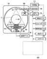
- FIG. 1 an embodiment of a multi-slice X-ray CT apparatus or scanner is shown and includes a gantry 100 and other devices or units.
- the gantry 100 is shown as viewed from the side, and further includes an X-ray tube 101, an annular frame 102, and a multi-row or two-dimensional array type X-ray detector 103.
- the X-ray tube 101 and the X-ray detector 103 are installed on an annular frame 102 that is supported so as to be rotatable about a rotation axis RA in a diametrical direction crossing the subject S.
- the rotating unit 107 rotates the frame 102 at a high speed of about 0.4 seconds / rotation while the subject S moves along the axis RA in the direction toward the back of the drawing or in the direction coming out of the drawing.
- the multi-slice X-ray CT apparatus further includes a high voltage generator 109 that generates X-rays in the X-ray tube 101 by applying a tube voltage to the X-ray tube 101 through the slip ring 108. X-rays are emitted toward the subject S, and the cross-sectional area of the subject is represented by a circle.
- the X-ray detector 103 is disposed on the opposite side of the X-ray tube 101 across the subject S, and detects X-rays emitted so as to be transmitted through the subject S.
- the X-ray CT apparatus or scanner further includes other devices that process the detected signals from the X-ray detector 103.
- a data acquisition circuit or data acquisition system (DAS) 104 converts the signal output from the X-ray detector 103 for each channel into a voltage signal, amplifies it, and further converts it into a digital signal.
- DAS data acquisition system
- X-ray detector 103 and DAS 104 are configured to process a predetermined total number of projections (TPPR) per revolution. This is at most 900 TPPR, between 900 TPPR and 1800 TPPR, and between 900 TPPR and 3600 TPPR.
- the data described above is sent to the preprocessing device 106 installed in the console outside the gantry 100 via the non-contact data transmitter 105.
- the preprocessing device 106 performs specific corrections such as sensitivity correction on the raw data.
- the storage device 112 stores the resulting data. This data is also called projection data in the stage immediately before the reconstruction process.
- the storage device 112 is connected to the system controller 110 via the data / control bus, but the reconstruction device 114, the display device 116, the input device 115, and the scan plan support apparatus 200 are the same.
- the scan plan support apparatus 200 includes a function of creating a scan plan by supporting an image engineer.
- the embodiment of the reconfiguration device 114 further includes various software and hardware components.
- the reconstruction device 114 of the CT apparatus effectively improves the spatial resolution using a successive approximation method.
- the reconstruction device 114 in this embodiment performs a total variation successive approximation (TVIR) algorithm.
- TVIR total variation successive approximation
- This algorithm performs an ordered subset contemporaneous reconstruction (OS-SART) step and a TV minimization step on the projection data. These two steps are implemented sequentially in the main loop where a large number of iterations are defined.
- an ordered subset contemporaneous reconstruction is performed on the projection data.
- Projection data is grouped into a predetermined number of subsets N, each having a specific number of views.
- each subset is, in one embodiment, processed sequentially. In another embodiment, these multiple subsets may be processed in parallel by utilizing a specific microprocessor, such as a plurality of central processing units (CPUs) or graphics processing units (GPUs). .
- CPUs central processing units
- GPUs graphics processing units
- the reconstruction device 114 further performs two important operations. That is, for each subset N, the embodiment of the reconstruction device 114 reprojects the image volume to form calculated projection data. The normalized difference between the measured projection data and the calculated projection data is then backprojected to reconstruct the updated image volume. More particularly, an embodiment of the reconstruction device 114 reprojects the image volume by using a ray-tracing method in which none of the system matrix coefficients are cached. Further, some embodiments of the reconstruction device 114 reproject all the rays in a subset at the same time, which is optionally implemented in parallel.
- an embodiment of the reconstruction device 114 uses pixel driven methods to backproject all of the normalized difference projection data in a subset to obtain the desired updated image volume.
- this operation is also optionally implemented in parallel. By applying these operations to all the subsets N, one OS-SART step is completed.
- This implementation and other implementations are optionally included within the scope of the present X-ray CT apparatus as set forth in the appended claims.
- an embodiment of the reconstruction device 114 optionally searches the positive step size using a line search strategy so that the target function of the current image volume is previously Make sure that the image volume is smaller than the target function.
- the total variation (TV) minimization step is optional in implementing this embodiment.
- the present embodiment further includes various software modules and hardware components for substantially improving the spatial resolution of the computed tomography image using a predetermined filter while the image is sequentially approximated.
- the resolution improvement device 117 of the CT apparatus effectively improves the spatial resolution.
- the resolution enhancement device 117 is operatively connected to other software modules and / or system components such as the storage device 112, the reconstruction device 114, the display device 116, and the input device 115 via a data / control bus.
- the resolution improvement device 117 does not necessarily perform the resolution function and / or related tasks alone in other embodiments.
- the resolution improving device 117 substantially improves the spatial resolution using a spatially varying low-pass filter that is also angle sensitive.
- the resolution improvement device 117 can optionally be part of another device, such as the reconstruction device 114.
- the reconstruction device 114 further includes a successive approximation unit (IR) 118 and a blur kernel 119.
- the blur kernel 119 substantially improves the spatial resolution as the successive approximation unit 118 sequentially approximates the image.
- the blur kernel 119 uses a spatially varying low-pass filter that is also angle sensitive to substantially improve the spatial resolution.
- step S100 image evaluation (captured image based on projection data (first projection data) obtained by imaging (measurement)) is acquired using a predetermined CT scanner system.
- step S110 the image evaluation is forward projected using at least a single ray to generate reprojection data.
- the exemplary forward projection in step S110 optionally considers a combination of system optics.
- the system optics here include focal spot size, detector size, and image voxel size. Image voxel size is not scaled in an exemplary process that substantially improves spatial resolution when sequentially approximating an image according to this embodiment.
- step S120 at least one predetermined angle variation low-pass filter is applied to the reprojection data to generate processed data.
- the angle-variable low-pass filter is a low-pass filter that fluctuates a filter coefficient (filter characteristic) according to the fan angle.
- step S130 the processed data of step S120 (projection data acquired by forward projection (second projection data)) and the measurement data used in step S100 (projection data acquired by imaging (first projection data) )) Is determined.
- step S140 the image evaluation is updated based on the difference determined in step S130, and an updated image is generated.
- step S150 the updated image is used as the image evaluation in step S110, and the predetermined number of times or until a predetermined condition is satisfied, step S110 to step S140. Is repeated. That is, step S150 determines whether the exemplary IR process according to this embodiment continues or ends the iteration.
- the system optics blur is overestimated to sharpen the image in certain situations.
- the IR acts as a deconvolution and substantially overcomes the limits of system optics such as focal spot size and detector element size. That is, the system blur kernel is simulated in forward projection to improve spatial resolution. According to the exemplary IR process, the image is substantially improved in spatial resolution by applying at least an angular variation low pass filter to the reprojection data in step S120 to generate processed data.
- the angle varying low-pass filter in step S120 is an example of a system blur kernel and optionally includes other additional variable components such as distance and angle combinations that affect the characteristics of the low-pass filter. Details of the angle variation low-pass filter in step S120 will be described later in relation to other drawings.
- the above-described exemplary IR process that substantially improves the spatial resolution according to the present embodiment, such as imaging of a computed tomography angiogram (CTA) of the lungs and coronary arteries where high-precision spatial resolution is required Improve diagnostic value in clinical CT applications.
- CTA computed tomography angiogram
- the focal spot FS and the detector array DET are arranged at specific positions with respect to the image pixel IP in the field of view FOV.
- the focal spot FS is projected as a relatively narrow strip or width dsx on the detector DET, as indicated by an angled dashed line.
- the focal spot FS is projected as a relatively long strip dsy on the detector DET, as indicated by the solid line passing through the image pixel IP at another angle.
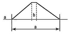
- FIG. 5 the particular characteristics of an example of an angle-dependent spatially varying low-pass filter according to this embodiment are shown.
- the characteristics of this angle-dependent spatially varying low-pass filter are explained in relation to the exemplary focal spot for the image pixel and detector shown in FIG.
- the characteristics of this angle-dependent spatially varying low-pass filter are characterized by a base a and a plateau b, which define the blur kernel size.
- the base a is the range of the filter as shown by the arrows pointing to both sides
- the plateau b is a partial area at the maximum value of the filter as shown by a pair of dashed lines
- it can be expressed by the following formulas (1) and (2).
- D is the distance between the focal spot FS and the detector DET
- S is the size of the effective source at a particular angle ⁇ .
- ⁇ is the channel angle.
- dsx is 1 mm and dsy is 7 mm.
- ⁇ sx is the distance from the focal spot.
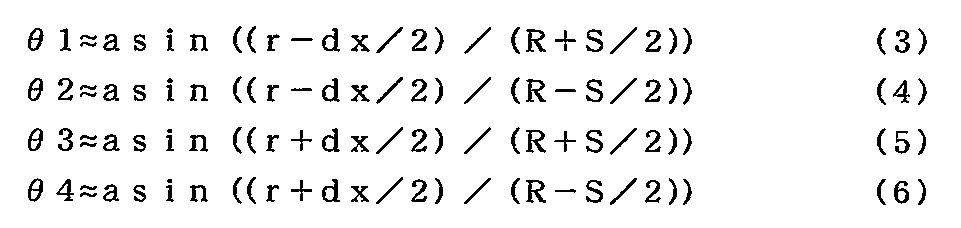
- the pixel is determined by ( ⁇ sx, ⁇ ). Further, ⁇ 1, ⁇ 2, ⁇ 3, and ⁇ 4 can be expressed by the following equations (3) to (6), respectively.
- r R
- and dx FOV / Nx.
- r is the distance from the isocenter (center of the field of view FOV) to the center of the image pixel IP
- dx is the size of the image pixel IP.
- R is the distance from the center of the field of view FOV to the center of the focal spot FS.
- the angular variability blur kernel is calculated based on the true geometry of the focal spot, such as spread or slope.
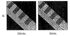
- FIGS. 6A to 6C the effect of an exemplary low-pass filter with angle-dependent spatial variation in the successive approximation method according to this embodiment is compared with other reconstruction methods.
- FBP filtered back projection
- FIG. 6A shows the spatial resolution of a given stripe at a specific exposure (300 milliamps / second (mAs) and 90 mAs) using a standard kernel (FBP-ST).
- FIG. 1 shows the spatial resolution of a given stripe at a specific exposure (300 milliamps / second (mAs) and 90 mAs) using a standard kernel (FBP-ST).
- FIG. 6B shows the spatial resolution of the same predetermined stripe at a specific exposure (300 mAs and 90 mAs) using a sharp convolution kernel (FBP-HR) with high frequency boost.
- FIG. 6C shows the spatial resolution of the same predetermined stripe at a specific exposure (300 mAs and 90 mAs) using an exemplary low pass filter with angle-dependent spatial variation in the successive approximation (IR) method according to this embodiment. Show. Between FIG. 6A and FIG. 6B, the resolution is substantially improved, but the noise level also appears to increase. On the other hand, as shown in FIG.
- the spatial resolution of the same predetermined stripe is substantially equal in both exposures.
- the use of the exemplary low pass filter with spatial variability that is angle-dependent spatial variability in the successive approximation method according to the present embodiment substantially improves the spatial resolution and substantially lowers the noise level at 300 mAs. ing.
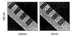
- FIGS. 7A and 7B the effect of an exemplary low-pass filter with angle-dependent spatial variation in the successive approximation method according to the present embodiment is shown using clinical data.
- FIG. 7A shows the spatial resolution of a lung image using the filtered back projection (FBP) method.
- FIG. 7B shows the spatial resolution of the same lung image using an exemplary low pass filter with angle-dependent spatial variation in the successive approximation (IR) method according to this embodiment.
- FBP filtered back projection
- FIG. 7B shows the spatial resolution of the same lung image using an exemplary low pass filter with angle-dependent spatial variation in the successive approximation (IR) method according to this embodiment.
- the spatial resolution is substantially improved by an exemplary low-pass filter with angle-dependent spatial variation in the successive approximation method according to this embodiment, as indicated by the circle.
- the noise level is substantially reduced.
- FIGS. 8A and 8B the effect of an exemplary low-pass filter with angle-dependent spatial variation in the successive approximation method according to this embodiment is compared with other reconstruction methods.
- the spatial resolution is improved by using a sharp convolution kernel (FBP-HR) with a high frequency boost instead of using the standard kernel (FBP-ST).
- FIG. 8A shows an exemplary low-pass filter with a standard kernel (FBP-ST), a sharp convolution kernel (FBP-HR) with high frequency boost, and angle-dependent spatial variation in the successive approximation (IR) method according to the present embodiment.
- the noise level in a predetermined exposure range when the spatial resolution is improved is shown.
- FBP-ST has the lowest noise level over the entire exposure range, but the spatial resolution is also lower compared to other methods.
- the level of spatial resolution in the reconstructed image is substantially improved, but the noise level is also high throughout the exposure range.
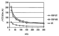
- FIG. 8B shows an example low-pass filter with a standard kernel (FBP-ST), a sharp convolution kernel (FBP-HR) with high frequency boost, and angle-dependent spatial variation in the successive approximation (IR) method according to the present embodiment.
- FBP-ST has the lowest modulation to noise ratio over the entire exposure range, but also has a lower spatial resolution compared to other methods.
- Both the FBP-HR method and the IR method have substantially improved the level of spatial resolution in the reconstructed image, but the modulation value-to-noise ratio is also high throughout the exposure range.
- the IR method according to the present embodiment has a substantially higher modulation-to-noise ratio occurring in the entire exposure range than in the FBP-HR method. Becomes clear.
- the low-pass filter that varies the filter coefficient according to the fan angle is used as the variable-angle low-pass filter.
- a low-pass filter with variable angle a low-pass filter that varies the filter coefficient according to the cone angle, or a low-pass filter that varies the filter coefficient according to at least one of the cone angle and the fan angle.
- a filter may be employed.
Landscapes
- Physics & Mathematics (AREA)
- Engineering & Computer Science (AREA)
- General Physics & Mathematics (AREA)
- Theoretical Computer Science (AREA)
- Algebra (AREA)
- Mathematical Analysis (AREA)
- Mathematical Optimization (AREA)
- Mathematical Physics (AREA)
- Pure & Applied Mathematics (AREA)
- Apparatus For Radiation Diagnosis (AREA)
- Image Processing (AREA)
Abstract
Provided is an X-ray computed tomography image-capturing device in which spatial resolution and noise suppression in successive approximation can be improved. This X-ray computed tomography image-capturing device comprises: a forward projection means that subjects a captured image created from first projection data based on image capturing, or the captured image that has been updated, to forward projection, and creates second projection data corresponding to at least one light-beam direction; a filter processing means that executes filter processing on the second projection data, which corresponds to said at least one light-beam direction, by using at least one angle-fluctuating low-pass filter; a calculating means that calculates the difference between the first projection data and the filter-processed second projection data; and an updating means that updates the captured image by using said difference.
Description
画像処理方法およびシステムに関し、より詳細には、代数再構成法(ART)、同時代数再構成法(SART)およびオーダードサブセット同時代数再構成法(OS-SART)などの逐次近似法への特定のローパスフィルタの応用に関する。
More specifically for image processing methods and systems, specific to successive approximation methods such as algebraic reconstruction (ART), simultaneous number reconstruction (SART) and ordered subset simultaneous number reconstruction (OS-SART) It relates to the application of low-pass filter.
ボリューム画像の再構成のために、逐次アルゴリズムが様々なグループによって開発されており、これには、全変動(TV)最小化逐次近似アルゴリズムが含まれる。逐次近似法(IR)には、更に、代数再構成法(ART)、同時代数再構成法(SART)またはオーダードサブセット同時代数再構成法(OS-SART)が含まれる。
¡Sequential algorithms have been developed by various groups for volume image reconstruction, including total variation (TV) minimizing successive approximation algorithms. The successive approximation method (IR) further includes an algebraic reconstruction method (ART), a contemporaneous number reconstruction method (SART), or an ordered subset contemporaneous number reconstruction method (OS-SART).
X線コンピュータ断層撮影(CT)では、従来型のフィルタ補正逆投影法(FBP)よりも画像の質の特定の特徴を改善するために、逐次近似法(IR)が幾分かの注目を集めてきた。IRは、計算の複雑さを管理可能な範囲に維持しながら、減衰線積分を正確に評価するフォワードモデルに基づく。他方で、FBPは、再構成カーネルに基づく。
In X-ray computed tomography (CT), successive approximation (IR) has received some attention to improve certain features of image quality over conventional filtered back projection (FBP). I came. IR is based on a forward model that accurately evaluates the attenuation line integral while maintaining computational complexity within a manageable range. On the other hand, FBP is based on a reconstructed kernel.
従来技術は、IR法およびFBP法の両方において空間解像度の改善を試みてきた。従来型のFBP法には、空間解像度を改善するために、高周波ブーストを伴うシャープな畳み込みカーネル(FBP-HR)を適用することにより、有限のフォーカルスポットサイズ、有限の検出器セルサイズ、検出器のクロストークおよび方位ブラーなど、画像化システムにおける空間的ブラーリングファクタを除去するという方法が存在する。IRは、再構成カーネルという概念を有していないが、画像解像度と画像ノイズとを依然として改善することができる。
The prior art has attempted to improve the spatial resolution in both the IR method and the FBP method. The conventional FBP method applies a sharp convolution kernel with high frequency boost (FBP-HR) to improve spatial resolution, thereby providing a finite focal spot size, finite detector cell size, detector There are methods to remove spatial blurring factors in imaging systems, such as crosstalk and orientation blur. IR does not have the concept of a reconstruction kernel, but it can still improve image resolution and image noise.
従来技術によるIR法は、特定のノイズ補償手段を用いて空間解像度を向上させる。従来技術によるあるIR法では、フォワードモデルにおいて、拡大されたボクセルフットプリントを用いるが、その際に、拡大されたボクセルの使用に起因して生じるいかなる不所望のオーバーシュートまたはアンダーシュートアーティファクトも除去するように設計された帯域抑制フィルタを組み合わせて用いている。従来技術による別のアプローチとして、点拡がり関数のライブラリを用いて、空間的に変動するボクセルフットプリントをモデル化している。
The IR method according to the prior art improves the spatial resolution by using specific noise compensation means. One prior art IR method uses an enlarged voxel footprint in the forward model, but removes any undesired overshoot or undershoot artifacts resulting from the use of the enlarged voxel. A band suppression filter designed as described above is used in combination. Another approach in the prior art is to model a spatially varying voxel footprint using a library of point spread functions.
上述したような従来技術による努力にもかかわらず、逐次近似法におけるノイズ抑制と空間解像度の改善との間には、依然としてトレードオフの関係が存在する。
Despite the efforts of the prior art as described above, there is still a trade-off between noise suppression and spatial resolution improvement in the successive approximation method.
目的は、逐次近似法におけるノイズ抑制と空間解像度とを改善することができるX線コンピュータ断層撮像装置を提供することである。
The object is to provide an X-ray computed tomography apparatus capable of improving noise suppression and spatial resolution in the successive approximation method.
本実施形態に係るX線コンピュータ断層撮像装置は、撮像に基づく第1の投影データから生成された撮像画像或いは更新された前記撮像画像を順投影し、少なくとも一つの光線方向に対応する第2の投影データを生成する順投影手段と、少なくとも1つの角度変動的なローパスフィルタを用いて、前記少なくとも一つの光線方向に対応する第2の投影データにフィルタ処理を実行するフィルタ処理手段と、前記第1の投影データと前記フィルタ処理後の第2の投影データとの差分を計算する計算手段と、前記差分を用いて前記撮像画像を更新する更新手段と、を具備するものである。
The X-ray computed tomography apparatus according to the present embodiment forward-projects a captured image generated from first projection data based on imaging or the updated captured image, and corresponds to at least one light beam direction. Forward projection means for generating projection data, filter processing means for performing filter processing on the second projection data corresponding to the at least one light ray direction using at least one angle-variable low-pass filter, and the first And calculating means for calculating a difference between the first projection data and the second projection data after the filtering process, and an updating means for updating the captured image using the difference.
以下、図面を参照しながら本実施形態に係わるX線CT装置を説明する。以下の説明において、複数の図面を通じて同様の参照番号が用いられている場合には、対応する構造を示すものとする。特に図1を参照すると、マルチスライスX線CT装置またはスキャナの実施形態が示されており、ガントリ100とそれ以外のデバイスまたはユニットとが含まれる。ガントリ100は、側面から見た様子が示されていて、X線管101と、環状フレーム102と、マルチローまたは2次元配列タイプのX線検出器103とを更に含む。X線管101とX線検出器103とは、被験者Sを横断する直径方向に、回転軸RAを中心として回転可能であるようにサポートされている環状フレーム102の上に設置されている。回転ユニット107は、被験者Sが軸RAに沿って図面の奥の方向にまたは図面から出てくる方向に移動する間、0.4秒/回転程度の高速度でフレーム102を回転させる。
Hereinafter, the X-ray CT apparatus according to the present embodiment will be described with reference to the drawings. In the following description, like reference numerals are used to indicate corresponding structures throughout the drawings. With particular reference to FIG. 1, an embodiment of a multi-slice X-ray CT apparatus or scanner is shown and includes a gantry 100 and other devices or units. The gantry 100 is shown as viewed from the side, and further includes an X-ray tube 101, an annular frame 102, and a multi-row or two-dimensional array type X-ray detector 103. The X-ray tube 101 and the X-ray detector 103 are installed on an annular frame 102 that is supported so as to be rotatable about a rotation axis RA in a diametrical direction crossing the subject S. The rotating unit 107 rotates the frame 102 at a high speed of about 0.4 seconds / rotation while the subject S moves along the axis RA in the direction toward the back of the drawing or in the direction coming out of the drawing.
マルチスライスX線CT装置は、更に、スリップリング108を通じてX線管101に管電圧を与えることによりX線管101にX線を発生させる高電圧発生器109を含む。X線は、被験者Sに向かって放射され、被験者の断面積は円によって表されている。X線検出器103は、被験者Sを横断してX線管101の反対側に配置され、被験者Sを通過して送信されるように放射されるX線を検出する。
The multi-slice X-ray CT apparatus further includes a high voltage generator 109 that generates X-rays in the X-ray tube 101 by applying a tube voltage to the X-ray tube 101 through the slip ring 108. X-rays are emitted toward the subject S, and the cross-sectional area of the subject is represented by a circle. The X-ray detector 103 is disposed on the opposite side of the X-ray tube 101 across the subject S, and detects X-rays emitted so as to be transmitted through the subject S.
更に図1を参照すると、X線CT装置またはスキャナは、X線検出器103からの検出された信号を処理する他のデバイスを更に含む。データ取得回路またはデータ取得システム(DAS)104は、それぞれのチャネルに対してX線検出器103から出力される信号を、電圧信号に変換し、それを増幅し、更にそれをデジタル信号に変換する。X線検出器103とDAS104とは、1回転当たり所定の総数の投影(TPPR)を処理するように構成されている。これは、高々900TPPR、900TPPRから1800TPPRまでの間、および900TPPRから3600TPPRまでの間である。
Still referring to FIG. 1, the X-ray CT apparatus or scanner further includes other devices that process the detected signals from the X-ray detector 103. A data acquisition circuit or data acquisition system (DAS) 104 converts the signal output from the X-ray detector 103 for each channel into a voltage signal, amplifies it, and further converts it into a digital signal. . X-ray detector 103 and DAS 104 are configured to process a predetermined total number of projections (TPPR) per revolution. This is at most 900 TPPR, between 900 TPPR and 1800 TPPR, and between 900 TPPR and 3600 TPPR.
上述したデータは、非接触データ送信機105を介して、ガントリ100の外部のコンソールの中に設置されている前処理デバイス106に送られる。前処理デバイス106は、生データに対して感度訂正など特定の訂正を実行する。次に、ストレージデバイス112が、結果として得られるデータを記憶する。このデータは、再構成処理の直前の段階において、投影データとも呼ばれる。ストレージデバイス112は、データ/コントロールバスを介してシステムコントローラ110に接続されるが、再構成デバイス114、表示デバイス116、入力デバイス115、そしてスキャンプランサポート装置200も同様である。スキャンプランサポート装置200は、画像担当技術者をサポートしてスキャンプランを作成する機能を含む。
The data described above is sent to the preprocessing device 106 installed in the console outside the gantry 100 via the non-contact data transmitter 105. The preprocessing device 106 performs specific corrections such as sensitivity correction on the raw data. Next, the storage device 112 stores the resulting data. This data is also called projection data in the stage immediately before the reconstruction process. The storage device 112 is connected to the system controller 110 via the data / control bus, but the reconstruction device 114, the display device 116, the input device 115, and the scan plan support apparatus 200 are the same. The scan plan support apparatus 200 includes a function of creating a scan plan by supporting an image engineer.
再構成デバイス114の実施形態は、様々なソフトウェアコンポーネントとハードウェアコンポーネントとを更に含む。一態様によれば、CT装置の再構成デバイス114は、逐次近似法を用いて空間解像度を効果的に改善する。ある実施形態では、本実施形態における再構成デバイス114は、全変動逐次近似(TVIR)アルゴリズムを実行する。このアルゴリズムは、オーダードサブセット同時代数再構成法(OS-SART)のステップと、TV最小化ステップとを、投影データに対して実行する。これら2つのステップは、多数回の反復が定められているメインループにおいてシーケンシャルに実装される。
The embodiment of the reconfiguration device 114 further includes various software and hardware components. According to one aspect, the reconstruction device 114 of the CT apparatus effectively improves the spatial resolution using a successive approximation method. In certain embodiments, the reconstruction device 114 in this embodiment performs a total variation successive approximation (TVIR) algorithm. This algorithm performs an ordered subset contemporaneous reconstruction (OS-SART) step and a TV minimization step on the projection data. These two steps are implemented sequentially in the main loop where a large number of iterations are defined.
TV最小化ステップの前に、再構成デバイス114の実施形態において、オーダードサブセット同時代数再構成法(OS-SART)が、投影データに対して実行される。投影データは、それぞれが特定の数のビューを有する所定の数の部分集合(サブセット)Nにグループ分けされる。オーダードサブセット同時代数再構成法(OS-SART)の間に、それぞれの部分集合は、ある実施形態では、シーケンシャルに処理される。別の実施形態では、これらの複数の部分集合を、複数の中央演算装置(CPU)やグラフィクス演算装置(GPU)などの特定のマイクロプロセッサを利用することにより、パラレルに処理することも可能である。
Prior to the TV minimization step, in the embodiment of the reconstruction device 114, an ordered subset contemporaneous reconstruction (OS-SART) is performed on the projection data. Projection data is grouped into a predetermined number of subsets N, each having a specific number of views. During the ordered subset contemporaneous reconstruction (OS-SART), each subset is, in one embodiment, processed sequentially. In another embodiment, these multiple subsets may be processed in parallel by utilizing a specific microprocessor, such as a plurality of central processing units (CPUs) or graphics processing units (GPUs). .
オーダードサブセット同時代数再構成法(OS-SART)の間に、再構成デバイス114は、2つの重要な動作を更に実行する。すなわち、それぞれの部分集合Nに対し、再構成デバイス114の実施形態は、画像ボリュームを再投影し、計算された投影データを形成する。そして、測定された投影データと計算された投影データとの間の正規化された差を逆投影して、更新された画像ボリュームを再構成する。更に詳細には、再構成デバイス114のある実施形態では、システム行列の係数がどれもキャッシュされないレイトレーシング(ray tracing)法を用いることにより、画像ボリュームを再投影する。更に、再構成デバイス114のある実施形態では、ある部分集合の中のすべてのレイを同時に再投影するが、これは、任意選択でパラレルに実装される。逆投影においては、再構成デバイス114のある実施形態では、ピクセル駆動法を用いて、ある部分集合の中の正規化された差投影データのすべてを逆投影して、所望の更新された画像ボリュームを形成する。再構成デバイス114はある部分集合の中のすべてのレイの和すなわち差投影データを逆投影して画像ボリュームを形成するので、この動作もまた、任意選択でパラレルに実装される。これらの動作が、すべての部分集合Nに対して適用されることにより、OS-SARTのステップが1つ終了する。この実装形態とそれ以外の実装形態とが、任意選択で、添付の特許請求の範囲に記載された本X線CT装置の範囲に含まれる。
During the ordered subset contemporaneous reconstruction (OS-SART), the reconstruction device 114 further performs two important operations. That is, for each subset N, the embodiment of the reconstruction device 114 reprojects the image volume to form calculated projection data. The normalized difference between the measured projection data and the calculated projection data is then backprojected to reconstruct the updated image volume. More particularly, an embodiment of the reconstruction device 114 reprojects the image volume by using a ray-tracing method in which none of the system matrix coefficients are cached. Further, some embodiments of the reconstruction device 114 reproject all the rays in a subset at the same time, which is optionally implemented in parallel. In backprojection, an embodiment of the reconstruction device 114 uses pixel driven methods to backproject all of the normalized difference projection data in a subset to obtain the desired updated image volume. Form. Since the reconstruction device 114 backprojects the sum or difference projection data of all rays in a subset to form an image volume, this operation is also optionally implemented in parallel. By applying these operations to all the subsets N, one OS-SART step is completed. This implementation and other implementations are optionally included within the scope of the present X-ray CT apparatus as set forth in the appended claims.
全変動(TV)最小化ステップでは、再構成デバイス114の実施形態は、任意選択で、ラインサーチ戦略を用いて正のステップサイズをサーチすることにより、現在の画像ボリュームの目的となる関数が以前の画像ボリュームの目的となる関数よりも小さいことを確認する。全変動(TV)最小化ステップは、本実施形態を実現する場合において、オプションである。
In a total variation (TV) minimization step, an embodiment of the reconstruction device 114 optionally searches the positive step size using a line search strategy so that the target function of the current image volume is previously Make sure that the image volume is smaller than the target function. The total variation (TV) minimization step is optional in implementing this embodiment.
本実施形態には、更に、画像が逐次近似されている間に所定のフィルタを用いてコンピュータ断層撮影画像の空間解像度を実質的に改善するための様々なソフトウェアモジュールやハードウェアコンポーネントが含まれる。一態様によれば、CT装置の解像度改善デバイス117が、空間解像度を効果的に改善する。ある実施形態では、解像度改善デバイス117は、ストレージデバイス112、再構成デバイス114、表示デバイス116および入力デバイス115など、他のソフトウェアモジュールおよび/またはシステムコンポーネントとデータ/コントロールバスを介して動作的に接続されている。このように、解像度改善デバイス117は、他の実施形態において解像度機能および/またはそれに関連するタスクを必ずしも単独で実行しているとは限らない。より詳細には後述するが、解像度改善デバイス117は、角度感知性でもある空間変動ローパスフィルタを用いて、空間解像度を実質的に改善する。
The present embodiment further includes various software modules and hardware components for substantially improving the spatial resolution of the computed tomography image using a predetermined filter while the image is sequentially approximated. According to one aspect, the resolution improvement device 117 of the CT apparatus effectively improves the spatial resolution. In some embodiments, the resolution enhancement device 117 is operatively connected to other software modules and / or system components such as the storage device 112, the reconstruction device 114, the display device 116, and the input device 115 via a data / control bus. Has been. Thus, the resolution improvement device 117 does not necessarily perform the resolution function and / or related tasks alone in other embodiments. As will be described in more detail below, the resolution improving device 117 substantially improves the spatial resolution using a spatially varying low-pass filter that is also angle sensitive.
図2を参照すると、解像度改善デバイス117は、任意選択で、再構成デバイス114などの他のデバイスの一部とすることも可能である。再構成デバイス114は、別個の解像度改善デバイス117を有する代わりに、逐次近似ユニット(IR)118とブラーカーネル119とを更に含む。本質的には、ブラーカーネル119は、逐次近似ユニット118が画像を逐次近似する際に、空間解像度を実質的に改善する。更なる詳細については後述するが、ブラーカーネル119は、角度感知性でもある空間変動的なローパスフィルタを用いて、空間解像度を実質的に改善する。
Referring to FIG. 2, the resolution improvement device 117 can optionally be part of another device, such as the reconstruction device 114. Instead of having a separate resolution improvement device 117, the reconstruction device 114 further includes a successive approximation unit (IR) 118 and a blur kernel 119. In essence, the blur kernel 119 substantially improves the spatial resolution as the successive approximation unit 118 sequentially approximates the image. As described in more detail below, the blur kernel 119 uses a spatially varying low-pass filter that is also angle sensitive to substantially improve the spatial resolution.
次に図3を参照すると、フローチャートが、本実施形態により画像を逐次近似する際に空間解像度を実質的に改善するプロセスに含まれる複数のステップを示している。この例示的なプロセスでは、空間変動し角度感知性も有するローパスフィルタを適用することによって、画像が逐次近似される際に、空間解像度が実質的に改善される。ステップS100では、所定のCTスキャナシステムを用いて、画像評価(撮像(測定)によって得られた投影データ(第1の投影データ)に基づく撮像画像)が取得される。ステップS110では、この画像評価が、少なくとも単一の光線を用いて順投影され、再投影データが生成される。ステップS110における例示的な順投影により、任意選択で、システムオプティクス(system optics)の組み合わせが考慮される。たとえば、ここでのシステムオプティクスには、フォーカルスポットサイズと、検出器サイズと、画像ボクセルサイズとが含まれる。画像ボクセルサイズは、本実施形態により画像を逐次近似する際に空間解像度を実質的に改善する例示的なプロセスでは、拡大されない。
Referring now to FIG. 3, a flowchart illustrates the steps involved in the process of substantially improving the spatial resolution when sequentially approximating an image according to this embodiment. In this exemplary process, the spatial resolution is substantially improved as the image is approximated sequentially by applying a low pass filter that is spatially varying and also angle sensitive. In step S100, image evaluation (captured image based on projection data (first projection data) obtained by imaging (measurement)) is acquired using a predetermined CT scanner system. In step S110, the image evaluation is forward projected using at least a single ray to generate reprojection data. The exemplary forward projection in step S110 optionally considers a combination of system optics. For example, the system optics here include focal spot size, detector size, and image voxel size. Image voxel size is not scaled in an exemplary process that substantially improves spatial resolution when sequentially approximating an image according to this embodiment.
ステップS120では、少なくとも一つの所定の角度変動ローパスフィルタが再投影データに適用され、処理済みデータが生成される。ここで、角度可変的なローパスフィルタとは、ファン角に応じてフィルタ係数(フィルタ特性)を変動させるローパスフィルタである。ステップS130では、ステップS120の処理済みデータ(順投影によって取得された投影データ(第2の投影データ))とステップS100で用いられた測定データ(撮像によって取得された投影データ(第1の投影データ))との間の差が決定される。結果的に、ステップS140において、ステップS130で決定された差に基づいて画像評価が更新され、更新された画像が生成される。本実施形態による例示的なIRプロセスでは、ステップS150において、この更新された画像をステップS110における画像評価として用いて、所定の回数だけ、または、所定の条件が満たされるまで、ステップS110からステップS140までが反復される。すなわち、ステップS150は、本実施形態による例示的なIRプロセスが反復を継続するのかまたは終了するのかを決定する。
In step S120, at least one predetermined angle variation low-pass filter is applied to the reprojection data to generate processed data. Here, the angle-variable low-pass filter is a low-pass filter that fluctuates a filter coefficient (filter characteristic) according to the fan angle. In step S130, the processed data of step S120 (projection data acquired by forward projection (second projection data)) and the measurement data used in step S100 (projection data acquired by imaging (first projection data) )) Is determined. As a result, in step S140, the image evaluation is updated based on the difference determined in step S130, and an updated image is generated. In the exemplary IR process according to the present embodiment, in step S150, the updated image is used as the image evaluation in step S110, and the predetermined number of times or until a predetermined condition is satisfied, step S110 to step S140. Is repeated. That is, step S150 determines whether the exemplary IR process according to this embodiment continues or ends the iteration.
更に図3を参照すると、システムオプティクスブラーが、特定の状況において画像を先鋭化するために過剰評価される。IRはデコンボリューションとして機能し、フォーカルスポットサイズや検出器の要素サイズなどのシステムオプティクスの限界を実質的に克服する。すなわち、システムブラーカーネルは、空間解像度を改善するために順投影においてシミュレーションがなされる。例示的なIRプロセスによれば、画像は、ステップS120において少なくとも角度変動ローパスフィルタを再投影データに適用して処理済みデータを生成することにより、空間解像度が実質的に改善される。ステップS120における角度変動ローパスフィルタは、システムブラーカーネルの一例であり、任意選択で、ローパスフィルタの特性に影響を与える距離と角度との組み合わせなど他の追加的な可変成分を含む。ステップS120の角度変動ローパスフィルタの詳細は、他の図面との関係で後述する。結果として、本実施形態による空間解像度を実質的に改善する上述の例示的なIRプロセスは、高精度の空間解像度が必要とされる肺や冠動脈のコンピュータ断層血管造影図(CTA)の画像化などの臨床的なCTの応用において、診断のための値を改善する。
Still referring to FIG. 3, the system optics blur is overestimated to sharpen the image in certain situations. The IR acts as a deconvolution and substantially overcomes the limits of system optics such as focal spot size and detector element size. That is, the system blur kernel is simulated in forward projection to improve spatial resolution. According to the exemplary IR process, the image is substantially improved in spatial resolution by applying at least an angular variation low pass filter to the reprojection data in step S120 to generate processed data. The angle varying low-pass filter in step S120 is an example of a system blur kernel and optionally includes other additional variable components such as distance and angle combinations that affect the characteristics of the low-pass filter. Details of the angle variation low-pass filter in step S120 will be described later in relation to other drawings. As a result, the above-described exemplary IR process that substantially improves the spatial resolution according to the present embodiment, such as imaging of a computed tomography angiogram (CTA) of the lungs and coronary arteries where high-precision spatial resolution is required Improve diagnostic value in clinical CT applications.
次に図4を参照すると、本実施形態による、画像ピクセルと検出器とに関係する例示的なフォーカルスポットの特定の特性が、図に示されている。フォーカルスポットFSと検出器配列DETとが、視野FOVにおける画像ピクセルIPに対する特定の位置に配置されている。フォーカルスポットFSは、ある角度の破線によって示されているように、検出器DET上の比較的幅の狭いストリップまたは幅dsxとして、投影される。他方で、フォーカルスポットFSは、別の角度で画像ピクセルIPを通過する実線によって示されているように、検出器DET上の比較的長いストリップdsyとして、投影される。
Referring now to FIG. 4, the particular characteristics of an exemplary focal spot related to image pixels and detectors according to this embodiment are shown in the figure. The focal spot FS and the detector array DET are arranged at specific positions with respect to the image pixel IP in the field of view FOV. The focal spot FS is projected as a relatively narrow strip or width dsx on the detector DET, as indicated by an angled dashed line. On the other hand, the focal spot FS is projected as a relatively long strip dsy on the detector DET, as indicated by the solid line passing through the image pixel IP at another angle.
次に図5を参照すると、本実施形態による角度依存的空間変動的なローパスフィルタの一例の特定の特性が図に示されている。この角度依存的空間変動的なローパスフィルタの特性が、図4に示されている画像ピクセルと検出器とに関する例示的なフォーカルスポットとの関係で説明される。この角度依存的空間変動的なローパスフィルタの特性は、ベースaとプラトーbとによって特徴付けられ、これらがブラーカーネルサイズを定義する。ベースaは両側に向けられた矢印によって示されているようにフィルタの範囲(レンジ)であり、プラトーbは1対の破線によって示されているようにフィルタの最大値における部分的な領域であり、例えば以下の式(1)、(2)で表すことができる。
Referring now to FIG. 5, the particular characteristics of an example of an angle-dependent spatially varying low-pass filter according to this embodiment are shown. The characteristics of this angle-dependent spatially varying low-pass filter are explained in relation to the exemplary focal spot for the image pixel and detector shown in FIG. The characteristics of this angle-dependent spatially varying low-pass filter are characterized by a base a and a plateau b, which define the blur kernel size. The base a is the range of the filter as shown by the arrows pointing to both sides, and the plateau b is a partial area at the maximum value of the filter as shown by a pair of dashed lines For example, it can be expressed by the following formulas (1) and (2).
a=(D-S/2)θ4-(D+S/2)θ1 (1)
b=(D-S/2)θ3-(D+S/2)θ2 (if b<0,set b=0) (2)
ここで、図4に示されているように、DはフォーカルスポットFSと検出器DETとの間の距離であり、Sは特定の角度γにおける有効ソースのサイズである。γはチャネル角度である。Sは、S=dsxcosγ+dsy|sinγ|によって与えられる。たとえば、dsxは1mmであり、dsyは7mmである。中心は、(∠sx=Rcosγ)によって近似される。ここで、∠sxはフォーカルスポットからの距離である。ピクセルは、(∠sx,γ)によって決定される。また、θ1、θ2、θ3、θ4は、それぞれ次の式(3)~(6)で表すことができる。
a = (DS−2) θ4− (D + S / 2) θ1 (1)
b = (DS−2) θ3− (D + S / 2) θ2 (if b <0, set b = 0) (2)
Here, as shown in FIG. 4, D is the distance between the focal spot FS and the detector DET, and S is the size of the effective source at a particular angle γ. γ is the channel angle. S is given by S = dsxcos γ + dsy | sin γ |. For example, dsx is 1 mm and dsy is 7 mm. The center is approximated by (∠sx = Rcosγ). Here, ∠sx is the distance from the focal spot. The pixel is determined by (∠sx, γ). Further, θ1, θ2, θ3, and θ4 can be expressed by the following equations (3) to (6), respectively.
b=(D-S/2)θ3-(D+S/2)θ2 (if b<0,set b=0) (2)
ここで、図4に示されているように、DはフォーカルスポットFSと検出器DETとの間の距離であり、Sは特定の角度γにおける有効ソースのサイズである。γはチャネル角度である。Sは、S=dsxcosγ+dsy|sinγ|によって与えられる。たとえば、dsxは1mmであり、dsyは7mmである。中心は、(∠sx=Rcosγ)によって近似される。ここで、∠sxはフォーカルスポットからの距離である。ピクセルは、(∠sx,γ)によって決定される。また、θ1、θ2、θ3、θ4は、それぞれ次の式(3)~(6)で表すことができる。
b = (DS−2) θ3− (D + S / 2) θ2 (if b <0, set b = 0) (2)
Here, as shown in FIG. 4, D is the distance between the focal spot FS and the detector DET, and S is the size of the effective source at a particular angle γ. γ is the channel angle. S is given by S = dsxcos γ + dsy | sin γ |. For example, dsx is 1 mm and dsy is 7 mm. The center is approximated by (∠sx = Rcosγ). Here, ∠sx is the distance from the focal spot. The pixel is determined by (∠sx, γ). Further, θ1, θ2, θ3, and θ4 can be expressed by the following equations (3) to (6), respectively.
ここで、r=R|sinγ|であり、dx=FOV/Nxである。図4に示されているように、rはアイソセンタ(視野FOVの中心)から画像ピクセルIPの中心までの距離であり、dxは画像ピクセルIPのサイズである。やはり図4に示されているように、Rは視野FOVの中心からフォーカルスポットFSの中心までの距離である。上述の数式(1)から(6)までに見られるように、角度依存的空間変動的な例示的なローパスフィルタの効果は、本実施形態による角度を含む空間変数に従属する。上述した近似とは対照的に、別の実施形態では、角度変動性のブラーカーネルは、拡がりや傾斜などフォーカルスポットの真の幾何学的性質(geometry)に基づいて計算される。
Here, r = R | sinγ | and dx = FOV / Nx. As shown in FIG. 4, r is the distance from the isocenter (center of the field of view FOV) to the center of the image pixel IP, and dx is the size of the image pixel IP. As also shown in FIG. 4, R is the distance from the center of the field of view FOV to the center of the focal spot FS. As can be seen from Equations (1) to (6) above, the effect of the exemplary low-pass filter with angle-dependent spatial variation depends on the spatial variable including the angle according to the present embodiment. In contrast to the approximations described above, in another embodiment, the angular variability blur kernel is calculated based on the true geometry of the focal spot, such as spread or slope.
次に図6Aから6Cを参照すると、本実施形態による逐次近似法における角度依存的空間変動的な例示的なローパスフィルタの効果が、他の再構成法と比較されている。従来型のフィルタ補正逆投影(FBP)法では、標準カーネル(FBP-ST)を用いる代わりに高周波ブーストを伴うシャープな畳み込みカーネル(FBP-HR)を用いることにより、空間解像度が改善される。図6Aは、標準カーネル(FBP-ST)を用いた特定の露光(300ミリアンペア/秒(mAs)および90mAs)における所定のストライプの空間解像度を示している。図6Bは、高周波ブーストを伴うシャープな畳み込みカーネル(FBP-HR)を用いた特定の露光(300mAsおよび90mAs)における同じ所定のストライプの空間解像度を示している。最後に、図6Cは、本実施形態による逐次近似(IR)法において角度依存的空間変動的な例示的なローパスフィルタを用いた特定の露光(300mAsおよび90mAs)における同じ所定のストライプの空間解像度を示している。図6Aと図6Bとの間では、解像度が実質的に改善されているが、ノイズレベルもまた増加しているように見える。他方で、図6Cに示されているように、本実施形態による逐次近似法において角度依存的空間変動的な例示的なローパスフィルタを用いると、両方の露光において同じ所定のストライプの空間解像度が実質的に改善されている。特に、本実施形態による逐次近似法において角度依存的空間変動的な空間変動性の例示的なローパスフィルタを用いると空間解像度が実質的に改善されると共に、300mAsにおいてノイズレベルが実質的により低くなっている。
Referring now to FIGS. 6A to 6C, the effect of an exemplary low-pass filter with angle-dependent spatial variation in the successive approximation method according to this embodiment is compared with other reconstruction methods. In the conventional filtered back projection (FBP) method, spatial resolution is improved by using a sharp convolution kernel (FBP-HR) with a high frequency boost instead of using the standard kernel (FBP-ST). FIG. 6A shows the spatial resolution of a given stripe at a specific exposure (300 milliamps / second (mAs) and 90 mAs) using a standard kernel (FBP-ST). FIG. 6B shows the spatial resolution of the same predetermined stripe at a specific exposure (300 mAs and 90 mAs) using a sharp convolution kernel (FBP-HR) with high frequency boost. Finally, FIG. 6C shows the spatial resolution of the same predetermined stripe at a specific exposure (300 mAs and 90 mAs) using an exemplary low pass filter with angle-dependent spatial variation in the successive approximation (IR) method according to this embodiment. Show. Between FIG. 6A and FIG. 6B, the resolution is substantially improved, but the noise level also appears to increase. On the other hand, as shown in FIG. 6C, using the exemplary low-pass filter with angle-dependent spatial variation in the successive approximation method according to the present embodiment, the spatial resolution of the same predetermined stripe is substantially equal in both exposures. Has been improved. In particular, the use of the exemplary low pass filter with spatial variability that is angle-dependent spatial variability in the successive approximation method according to the present embodiment substantially improves the spatial resolution and substantially lowers the noise level at 300 mAs. ing.
次に図7Aおよび図7Bを参照すると、本実施形態による逐次近似法における角度依存的空間変動的な例示的なローパスフィルタの効果が、臨床データを用いて示されている。図7Aは、フィルタ補正逆投影(FBP)法を用いた肺の画像の空間解像度を示している。図7Bは、本実施形態による逐次近似(IR)法において角度依存的空間変動的な例示的なローパスフィルタを用いた同じ肺の画像の空間解像度を示している。肺の画像の特定の領域においては、円によって示されているように、本実施形態による逐次近似法における角度依存的空間変動的な例示的なローパスフィルタによって空間解像度が実質的に改善されると共に、ノイズレベルが実質的に低下している。
Referring now to FIGS. 7A and 7B, the effect of an exemplary low-pass filter with angle-dependent spatial variation in the successive approximation method according to the present embodiment is shown using clinical data. FIG. 7A shows the spatial resolution of a lung image using the filtered back projection (FBP) method. FIG. 7B shows the spatial resolution of the same lung image using an exemplary low pass filter with angle-dependent spatial variation in the successive approximation (IR) method according to this embodiment. In a particular region of the lung image, the spatial resolution is substantially improved by an exemplary low-pass filter with angle-dependent spatial variation in the successive approximation method according to this embodiment, as indicated by the circle. The noise level is substantially reduced.
次に図8Aおよび図8Bを参照すると、本実施形態による逐次近似法における角度依存的空間変動的な例示的なローパスフィルタの効果が、他の再構成法と比較されている。従来型のフィルタ補正逆投影(FBP)法では、標準カーネル(FBP-ST)を用いる代わりに高周波ブーストを伴うシャープな畳み込みカーネル(FBP-HR)を用いることにより、空間解像度が改善される。図8Aは、標準カーネル(FBP-ST)と高周波ブーストを伴うシャープな畳み込みカーネル(FBP-HR)と本実施形態による逐次近似(IR)法における角度依存的空間変動的な例示的なローパスフィルタとの間で、空間解像度が改善される場合の所定の露光範囲でのノイズレベルを示している。FBP-STは、露光範囲の全体でノイズレベルが最低であるが、空間解像度も他の方法と比較するとより低くなっている。FBP-HR法とIR法は、共に、再構成された画像における空間解像度のレベルが実質的に改善されているが、露光範囲の全体でノイズレベルも高くなっている。FBP-HR法とIR法とを比較することにより、本実施形態によるIR法は、FBP-HR法の場合よりも、露光範囲の全体において生じるノイズレベルが低くなっていることが明らかになる。
Referring now to FIGS. 8A and 8B, the effect of an exemplary low-pass filter with angle-dependent spatial variation in the successive approximation method according to this embodiment is compared with other reconstruction methods. In the conventional filtered back projection (FBP) method, the spatial resolution is improved by using a sharp convolution kernel (FBP-HR) with a high frequency boost instead of using the standard kernel (FBP-ST). FIG. 8A shows an exemplary low-pass filter with a standard kernel (FBP-ST), a sharp convolution kernel (FBP-HR) with high frequency boost, and angle-dependent spatial variation in the successive approximation (IR) method according to the present embodiment. The noise level in a predetermined exposure range when the spatial resolution is improved is shown. FBP-ST has the lowest noise level over the entire exposure range, but the spatial resolution is also lower compared to other methods. In both the FBP-HR method and the IR method, the level of spatial resolution in the reconstructed image is substantially improved, but the noise level is also high throughout the exposure range. By comparing the FBP-HR method and the IR method, it becomes clear that the noise level generated in the entire exposure range is lower in the IR method according to the present embodiment than in the FBP-HR method.
図8Bは、標準カーネル(FBP-ST)と高周波ブーストを伴うシャープな畳み込みカーネル(FBP-HR)と本実施形態による逐次近似(IR)法における角度依存的空間変動的な例示的なローパスフィルタとの間で、空間解像度が改善される場合の所定の露光範囲での変調対ノイズ比を示している。FBP-STは、他の方法と比較すると、露光範囲の全体で変調対ノイズ比が最低であるが、空間解像度もまた低い。FBP-HR法とIR法は、共に、再構成された画像における空間解像度のレベルが実質的に改善されているが、露光範囲の全体で変調値対ノイズ比も高くなっている。FBP-HR法とIR法とを比較することにより、本実施形態によるIR法は、FBP-HR法の場合よりも、露光範囲の全体において生じる変調対ノイズ比が実質的に高くなっていることが明らかになる。
FIG. 8B shows an example low-pass filter with a standard kernel (FBP-ST), a sharp convolution kernel (FBP-HR) with high frequency boost, and angle-dependent spatial variation in the successive approximation (IR) method according to the present embodiment. The modulation-to-noise ratio in a predetermined exposure range when the spatial resolution is improved is shown. FBP-ST has the lowest modulation to noise ratio over the entire exposure range, but also has a lower spatial resolution compared to other methods. Both the FBP-HR method and the IR method have substantially improved the level of spatial resolution in the reconstructed image, but the modulation value-to-noise ratio is also high throughout the exposure range. By comparing the FBP-HR method with the IR method, the IR method according to the present embodiment has a substantially higher modulation-to-noise ratio occurring in the entire exposure range than in the FBP-HR method. Becomes clear.
なお、上記実施形態では、角度可変的なローパスフィルタとして、ファン角に応じてフィルタ係数を変動させるローパスフィルタを用いる場合を例示した。しかしながら、当該例に拘泥されず、例えば、角度可変的なローパスフィルタとして、コーン角に応じてフィルタ係数を変動させるローパスフィルタ、或いはコーン角及びファン角の少なくとも一方に応じてフィルタ係数を変動させるローパスフィルタを採用するようにしてもよい。
In the above-described embodiment, the case where the low-pass filter that varies the filter coefficient according to the fan angle is used as the variable-angle low-pass filter. However, without being limited to this example, for example, as a low-pass filter with variable angle, a low-pass filter that varies the filter coefficient according to the cone angle, or a low-pass filter that varies the filter coefficient according to at least one of the cone angle and the fan angle. A filter may be employed.
しかし、本実施形態の多くの特徴や効果について本実施形態の構成および機能の詳細と共に以上で説明してきたが、本開示は説明目的であるに過ぎず、細部、特に構成要素の形状や大きさや配列に関して、また、ソフトウェアやハードウェアや両者の組み合わせによる実装形態に関して変更がなされたとしても、それらの変化は、特許請求の範囲の記載において用いられている用語の広く一般的な意味によって示される全範囲に関し、本発明の原理の範囲に含まれることを理解されたい。
However, although many features and effects of the present embodiment have been described above together with the details of the configuration and functions of the present embodiment, the present disclosure is for illustrative purposes only, and details, particularly the shape and size of the components Even if changes are made to the arrangement and to the implementation by software, hardware or a combination of both, such changes are indicated by the broad and general meaning of the terms used in the claims. It should be understood that the entire scope is within the scope of the principles of the present invention.
Claims (11)
- 撮像に基づく第1の投影データから生成された撮像画像或いは更新された前記撮像画像を順投影し、少なくとも一つの光線方向に対応する第2の投影データを生成する順投影手段と、
少なくとも1つの角度変動的なローパスフィルタを用いて、前記少なくとも一つの光線方向に対応する第2の投影データにフィルタ処理を実行するフィルタ処理手段と、
前記第1の投影データと前記フィルタ処理後の第2の投影データとの差分を計算する計算手段と、
前記差分を用いて前記撮像画像を更新する更新手段と、
を具備することを特徴とするX線コンピュータ断層撮像装置。 Forward projection means for forwardly projecting the captured image generated from the first projection data based on imaging or the updated captured image, and generating second projection data corresponding to at least one light beam direction;
Filter processing means for performing filter processing on the second projection data corresponding to the at least one light beam direction using at least one angle-variable low-pass filter;
Calculation means for calculating a difference between the first projection data and the second projection data after the filtering;
Updating means for updating the captured image using the difference;
An X-ray computed tomography apparatus comprising: - 前記角度変動的なローパスフィルタは、ファン角に応じてフィルタ係数を変動させることを特徴とする請求項1記載のX線コンピュータ断層撮像装置。 The X-ray computed tomography apparatus according to claim 1, wherein the angle-variable low-pass filter varies a filter coefficient according to a fan angle.
- 前記角度変動的なローパスフィルタは、コーン角に応じてフィルタ係数を変動させることを特徴とする請求項1又は2記載のX線コンピュータ断層撮像装置。 The X-ray computed tomography apparatus according to claim 1 or 2, wherein the angle-variable low-pass filter varies a filter coefficient according to a cone angle.
- 前記角度変動的なローパスフィルタは、フォーカルスポットサイズと検出器サイズと画像ユニットサイズとの組み合わせに基づく角度変動的なブラーカーネルを有することを特徴とする請求項1乃至3のうちいずれか一項記載のX線コンピュータ断層撮像装置。 The angle-variable low-pass filter includes an angle-variable blur kernel based on a combination of a focal spot size, a detector size, and an image unit size. X-ray computed tomography apparatus.
- 前記フィルタ処理手段は、前記ブラーカーネルを制御して臨床的に所望の空間解像度を取得することを特徴とする請求項4記載のX線コンピュータ断層撮像装置。 5. The X-ray computed tomography apparatus according to claim 4, wherein the filter processing means controls the blur kernel to acquire a clinically desired spatial resolution.
- 前記撮像に基づく第1の投影データから生成された撮像画像は、フィルタ補正逆投影によって生成され、
前記フィルタ処理手段は、前記撮像に基づく第1の投影データから生成された撮像画像の解像度に基づいて、前記ブラーカーネルを制御することを特徴とする請求項5記載のX線コンピュータ断層撮像装置。 The captured image generated from the first projection data based on the imaging is generated by filtered back projection,
6. The X-ray computed tomography apparatus according to claim 5, wherein the filter processing unit controls the blur kernel based on a resolution of a captured image generated from the first projection data based on the imaging. - 前記フィルタ処理手段は、近似されたフォーカルスポットの幾何学的性質に基づいて計算された前記ブラーカーネルを用いることを特徴とする請求項4記載のX線コンピュータ断層撮像装置。 5. The X-ray computed tomography apparatus according to claim 4, wherein the filter processing unit uses the blur kernel calculated based on the geometric property of the approximated focal spot.
- 近似されたフォーカルスポットの幾何学的性質は、現実の延長されたフットプリントを伴うフォーカルスポットに基づいて計算されることを特徴とする請求項7記載のX線コンピュータ断層撮像装置。 The X-ray computed tomography apparatus according to claim 7, wherein the geometric property of the approximated focal spot is calculated based on the focal spot with an actual extended footprint.
- 前記フィルタ処理手段は、次の式(1)、(2)のベースaとプラトーbとを用いて決定された前記角度変動的なブラーカーネルのサイズを利用するものであって、
a=(D-S/2)θ4-(D+S/2)θ1 (1)
b=(D-S/2)θ3-(D+S/2)θ2 (if b<0,set b=0) (2)
ここで、Dはフォーカルスポットと検出器との間の距離であり、Sは所定の角度における有効ソースサイズであり、θ1からθ4までは、次の式(3)、(4)、(5)、(6)で与えられ、

a = (DS−2) θ4− (D + S / 2) θ1 (1)
b = (DS−2) θ3− (D + S / 2) θ2 (if b <0, set b = 0) (2)
Here, D is the distance between the focal spot and the detector, S is the effective source size at a predetermined angle, and from θ1 to θ4, the following equations (3), (4), (5) , (6)
- 前記フィルタ処理手段は、フォーカルスポットの真の幾何学的性質に基づいて計算された前記角度変動的なブラーカーネルを用いることを特徴とする請求項4記載のX線コンピュータ断層撮像装置。 5. The X-ray computed tomography apparatus according to claim 4, wherein the filtering means uses the angle-variable blur kernel calculated based on a true geometric property of a focal spot.
- 前記更新手段は、前記撮像画像を更新すると共に正規化することを特徴とする請求項1乃至8のうちいずれか一項記載のX線コンピュータ断層撮像装置。 The X-ray computed tomography apparatus according to any one of claims 1 to 8, wherein the updating unit updates and normalizes the captured image.
Priority Applications (2)
| Application Number | Priority Date | Filing Date | Title |
|---|---|---|---|
| EP13736045.9A EP2803320A4 (en) | 2012-01-10 | 2013-01-09 | X-ray computed tomography device (x-ray ct device) using successive approximation |
| CN201380005108.3A CN104039233B (en) | 2012-01-10 | 2013-01-09 | Use the X-ray computed tomograohy apparatus (X ray CT device) of iterative approximation |
Applications Claiming Priority (2)
| Application Number | Priority Date | Filing Date | Title |
|---|---|---|---|
| US13/347,398 | 2012-01-10 | ||
| US13/347,398 US8837797B2 (en) | 2012-01-10 | 2012-01-10 | Spatial resolution improvement in computer tomography (CT) using iterative reconstruction |
Publications (1)
| Publication Number | Publication Date |
|---|---|
| WO2013105583A1 true WO2013105583A1 (en) | 2013-07-18 |
Family
ID=48743968
Family Applications (1)
| Application Number | Title | Priority Date | Filing Date |
|---|---|---|---|
| PCT/JP2013/050240 WO2013105583A1 (en) | 2012-01-10 | 2013-01-09 | X-ray computed tomography device (x-ray ct device) using successive approximation |
Country Status (5)
| Country | Link |
|---|---|
| US (1) | US8837797B2 (en) |
| EP (1) | EP2803320A4 (en) |
| JP (1) | JP6062250B2 (en) |
| CN (1) | CN104039233B (en) |
| WO (1) | WO2013105583A1 (en) |
Cited By (5)
| Publication number | Priority date | Publication date | Assignee | Title |
|---|---|---|---|---|
| JP2016198504A (en) * | 2015-04-08 | 2016-12-01 | 株式会社東芝 | Image generation device, x-ray computer tomography device and image generation method |
| JP2018110714A (en) * | 2017-01-12 | 2018-07-19 | オムロン株式会社 | Image processing device and image processing method |
| WO2019230740A1 (en) * | 2018-05-28 | 2019-12-05 | 国立研究開発法人理化学研究所 | Method and device for acquiring tomographic image data by oversampling, and control program |
| US11375964B2 (en) | 2018-05-28 | 2022-07-05 | Riken | Acquisition method, acquisition device, and control program for tomographic image data by means of angular offset |
| WO2022158575A1 (en) | 2021-01-21 | 2022-07-28 | 国立研究開発法人理化学研究所 | System, method, and program for tomographic imaging, and recording medium in which program is recorded |
Families Citing this family (4)
| Publication number | Priority date | Publication date | Assignee | Title |
|---|---|---|---|---|
| US8885903B2 (en) * | 2011-11-16 | 2014-11-11 | General Electric Company | Method and apparatus for statistical iterative reconstruction |
| JP6161003B2 (en) * | 2013-11-11 | 2017-07-12 | 東芝Itコントロールシステム株式会社 | Program, reconstruction apparatus and tomography apparatus |
| CN104408753B (en) * | 2014-10-27 | 2017-04-12 | 浙江大学 | Self-adaptive iteration scattering correction method of cone beam CT |
| JP7046543B2 (en) * | 2017-09-27 | 2022-04-04 | 浜松ホトニクス株式会社 | Tomographic imaging device and tomographic imaging method |
Citations (3)
| Publication number | Priority date | Publication date | Assignee | Title |
|---|---|---|---|---|
| JP2009510400A (en) * | 2005-09-26 | 2009-03-12 | コーニンクレッカ フィリップス エレクトロニクス エヌ ヴィ | System, method and image processor for iterative image reconstruction with enhanced noise suppression filtering function |
| WO2010016425A1 (en) * | 2008-08-07 | 2010-02-11 | 株式会社 日立メディコ | X-ray ct image formation method and x-ray ct device using same |
| WO2011122613A1 (en) * | 2010-03-30 | 2011-10-06 | 株式会社 日立メディコ | Reconstruction computing device, reconstruction computing method, and x-ray ct device |
Family Cites Families (13)
| Publication number | Priority date | Publication date | Assignee | Title |
|---|---|---|---|---|
| JPS6385480A (en) * | 1986-09-30 | 1988-04-15 | Shimadzu Corp | Projecting device |
| US6917663B2 (en) * | 2003-06-16 | 2005-07-12 | Kabushiki Kaisha Toshiba | Cone-beam reconstruction apparatus and computed tomography apparatus |
| JP4535795B2 (en) * | 2004-07-12 | 2010-09-01 | ジーイー・メディカル・システムズ・グローバル・テクノロジー・カンパニー・エルエルシー | Image processing apparatus and X-ray CT system |
| US7424088B2 (en) * | 2004-09-29 | 2008-09-09 | Kabushiki Kaisha Toshiba | Image reconstruction method using Hilbert transform |
| US7251306B2 (en) * | 2004-11-17 | 2007-07-31 | General Electric Company | Methods, apparatus, and software to facilitate iterative reconstruction of images |
| CN1640361A (en) * | 2005-01-06 | 2005-07-20 | 东南大学 | Positive computerized tomography restoration method for multi-phase horizontal set |
| US7583780B2 (en) * | 2006-06-22 | 2009-09-01 | General Electric Company | Systems and methods for improving a resolution of an image |
| US8655033B2 (en) | 2009-10-28 | 2014-02-18 | General Electric Company | Iterative reconstruction |
| US20110164031A1 (en) * | 2010-01-06 | 2011-07-07 | Kabushiki Kaisha Toshiba | Novel implementation of total variation (tv) minimization iterative reconstruction algorithm suitable for parallel computation |
| US8478013B2 (en) * | 2010-05-25 | 2013-07-02 | Kabushiki Kaisha Toshiba | Automatic motion map generation in helical CT |
| US8615118B2 (en) * | 2010-05-28 | 2013-12-24 | The University Of Maryland, Baltimore | Techniques for tomographic image by background subtraction |
| JP2013536601A (en) * | 2010-06-21 | 2013-09-19 | アイマックス コーポレイション | Double stack projection |
| US8903150B2 (en) * | 2011-07-31 | 2014-12-02 | Varian Medical Systems, Inc. | Filtration imaging enhancement method and system |
-
2012
- 2012-01-10 US US13/347,398 patent/US8837797B2/en active Active
-
2013
- 2013-01-09 CN CN201380005108.3A patent/CN104039233B/en active Active
- 2013-01-09 WO PCT/JP2013/050240 patent/WO2013105583A1/en active Application Filing
- 2013-01-09 EP EP13736045.9A patent/EP2803320A4/en not_active Withdrawn
- 2013-01-10 JP JP2013002456A patent/JP6062250B2/en active Active
Patent Citations (3)
| Publication number | Priority date | Publication date | Assignee | Title |
|---|---|---|---|---|
| JP2009510400A (en) * | 2005-09-26 | 2009-03-12 | コーニンクレッカ フィリップス エレクトロニクス エヌ ヴィ | System, method and image processor for iterative image reconstruction with enhanced noise suppression filtering function |
| WO2010016425A1 (en) * | 2008-08-07 | 2010-02-11 | 株式会社 日立メディコ | X-ray ct image formation method and x-ray ct device using same |
| WO2011122613A1 (en) * | 2010-03-30 | 2011-10-06 | 株式会社 日立メディコ | Reconstruction computing device, reconstruction computing method, and x-ray ct device |
Cited By (12)
| Publication number | Priority date | Publication date | Assignee | Title |
|---|---|---|---|---|
| JP2016198504A (en) * | 2015-04-08 | 2016-12-01 | 株式会社東芝 | Image generation device, x-ray computer tomography device and image generation method |
| JP7187131B2 (en) | 2015-04-08 | 2022-12-12 | キヤノンメディカルシステムズ株式会社 | Image generation device, X-ray computed tomography device and image generation method |
| JP2018110714A (en) * | 2017-01-12 | 2018-07-19 | オムロン株式会社 | Image processing device and image processing method |
| WO2018131252A1 (en) * | 2017-01-12 | 2018-07-19 | オムロン株式会社 | Image processing device, image processing method, and program |
| CN109890294A (en) * | 2017-01-12 | 2019-06-14 | 欧姆龙株式会社 | Image processing apparatus, image processing method and program |
| US10964003B2 (en) | 2017-01-12 | 2021-03-30 | Omron Corporation | Image processing apparatus, image processing method, and program |
| WO2019230740A1 (en) * | 2018-05-28 | 2019-12-05 | 国立研究開発法人理化学研究所 | Method and device for acquiring tomographic image data by oversampling, and control program |
| JPWO2019230740A1 (en) * | 2018-05-28 | 2021-08-26 | 国立研究開発法人理化学研究所 | Tomographic image data acquisition method by oversampling, acquisition device, and control program |
| US11307153B2 (en) | 2018-05-28 | 2022-04-19 | Riken | Method and device for acquiring tomographic image data by oversampling, and control program |
| US11375964B2 (en) | 2018-05-28 | 2022-07-05 | Riken | Acquisition method, acquisition device, and control program for tomographic image data by means of angular offset |
| JP7236110B2 (en) | 2018-05-28 | 2023-03-09 | 国立研究開発法人理化学研究所 | Acquisition method of tomographic image data by oversampling, acquisition device, and control program |
| WO2022158575A1 (en) | 2021-01-21 | 2022-07-28 | 国立研究開発法人理化学研究所 | System, method, and program for tomographic imaging, and recording medium in which program is recorded |
Also Published As
| Publication number | Publication date |
|---|---|
| CN104039233A (en) | 2014-09-10 |
| EP2803320A4 (en) | 2016-08-03 |
| CN104039233B (en) | 2016-10-12 |
| US20130177225A1 (en) | 2013-07-11 |
| EP2803320A1 (en) | 2014-11-19 |
| JP6062250B2 (en) | 2017-01-18 |
| US8837797B2 (en) | 2014-09-16 |
| JP2013141608A (en) | 2013-07-22 |
Similar Documents
| Publication | Publication Date | Title |
|---|---|---|
| JP6062250B2 (en) | X-ray computed tomography (X-ray CT) using the successive approximation method | |
| JP6208271B2 (en) | Medical image processing device | |
| JP6956505B2 (en) | Image processing device, X-ray CT device and image processing method | |
| JP6139092B2 (en) | X-ray CT apparatus and system | |
| US8625870B2 (en) | Method and system for supplementing detail image in successive multi-scale reconstruction | |
| EP2504811A2 (en) | Enhanced image data/dose reduction | |
| US9025838B2 (en) | Apparatus and method for hybrid reconstruction of an object from projection data | |
| CN105118039B (en) | Realize the method and system that pyramidal CT image is rebuild | |
| JP2013085965A (en) | Method and system for substantially reducing artifact in circular cone beam computer tomography (ct) | |
| US11238625B2 (en) | Imaging system extended field-of-view | |
| JP6222813B2 (en) | X-ray computed tomography apparatus, image processing apparatus and image processing method | |
| KR102234138B1 (en) | Image processing apparatus, image processing method and program | |
| JP6505513B2 (en) | X-ray computed tomography imaging apparatus and medical image processing apparatus | |
| CN111795949B (en) | Anti-scatter imaging method and device | |
| US6973157B2 (en) | Method and apparatus for weighted backprojection reconstruction in 3D X-ray imaging | |
| CN110073412B (en) | Image noise estimation using alternating negatives | |
| JP7187131B2 (en) | Image generation device, X-ray computed tomography device and image generation method | |
| JP4387758B2 (en) | SPECT apparatus and SPECT image reconstruction method | |
| JP2016039902A (en) | X-ray computer tomographic apparatus and medical image processing apparatus | |
| US11967005B2 (en) | Cone beam artifact correction for gated imaging | |
| US10902647B2 (en) | System for iteratively reconstructing computed tomography images through three domains |
Legal Events
| Date | Code | Title | Description |
|---|---|---|---|
| 121 | Ep: the epo has been informed by wipo that ep was designated in this application |
Ref document number: 13736045 Country of ref document: EP Kind code of ref document: A1 |
|
| NENP | Non-entry into the national phase |
Ref country code: DE |
|
| WWE | Wipo information: entry into national phase |
Ref document number: 2013736045 Country of ref document: EP |
|
| NENP | Non-entry into the national phase |
Ref country code: JP |