WO2013105453A1 - Method for operating flash vessel - Google Patents
Method for operating flash vessel Download PDFInfo
- Publication number
- WO2013105453A1 WO2013105453A1 PCT/JP2012/083947 JP2012083947W WO2013105453A1 WO 2013105453 A1 WO2013105453 A1 WO 2013105453A1 JP 2012083947 W JP2012083947 W JP 2012083947W WO 2013105453 A1 WO2013105453 A1 WO 2013105453A1
- Authority
- WO
- WIPO (PCT)
- Prior art keywords
- slurry
- liquid level
- flash vessel
- leaching
- detected
- Prior art date
Links
Images


Classifications
-
- C—CHEMISTRY; METALLURGY
- C22—METALLURGY; FERROUS OR NON-FERROUS ALLOYS; TREATMENT OF ALLOYS OR NON-FERROUS METALS
- C22B—PRODUCTION AND REFINING OF METALS; PRETREATMENT OF RAW MATERIALS
- C22B23/00—Obtaining nickel or cobalt
- C22B23/04—Obtaining nickel or cobalt by wet processes
- C22B23/0407—Leaching processes
- C22B23/0415—Leaching processes with acids or salt solutions except ammonium salts solutions
-
- C—CHEMISTRY; METALLURGY
- C22—METALLURGY; FERROUS OR NON-FERROUS ALLOYS; TREATMENT OF ALLOYS OR NON-FERROUS METALS
- C22B—PRODUCTION AND REFINING OF METALS; PRETREATMENT OF RAW MATERIALS
- C22B3/00—Extraction of metal compounds from ores or concentrates by wet processes
- C22B3/02—Apparatus therefor
-
- B—PERFORMING OPERATIONS; TRANSPORTING
- B01—PHYSICAL OR CHEMICAL PROCESSES OR APPARATUS IN GENERAL
- B01J—CHEMICAL OR PHYSICAL PROCESSES, e.g. CATALYSIS OR COLLOID CHEMISTRY; THEIR RELEVANT APPARATUS
- B01J3/00—Processes of utilising sub-atmospheric or super-atmospheric pressure to effect chemical or physical change of matter; Apparatus therefor
- B01J3/04—Pressure vessels, e.g. autoclaves
-
- B—PERFORMING OPERATIONS; TRANSPORTING
- B01—PHYSICAL OR CHEMICAL PROCESSES OR APPARATUS IN GENERAL
- B01J—CHEMICAL OR PHYSICAL PROCESSES, e.g. CATALYSIS OR COLLOID CHEMISTRY; THEIR RELEVANT APPARATUS
- B01J4/00—Feed or outlet devices; Feed or outlet control devices
- B01J4/008—Feed or outlet control devices
-
- C—CHEMISTRY; METALLURGY
- C22—METALLURGY; FERROUS OR NON-FERROUS ALLOYS; TREATMENT OF ALLOYS OR NON-FERROUS METALS
- C22B—PRODUCTION AND REFINING OF METALS; PRETREATMENT OF RAW MATERIALS
- C22B3/00—Extraction of metal compounds from ores or concentrates by wet processes
- C22B3/04—Extraction of metal compounds from ores or concentrates by wet processes by leaching
-
- B—PERFORMING OPERATIONS; TRANSPORTING
- B01—PHYSICAL OR CHEMICAL PROCESSES OR APPARATUS IN GENERAL
- B01J—CHEMICAL OR PHYSICAL PROCESSES, e.g. CATALYSIS OR COLLOID CHEMISTRY; THEIR RELEVANT APPARATUS
- B01J2219/00—Chemical, physical or physico-chemical processes in general; Their relevant apparatus
- B01J2219/00049—Controlling or regulating processes
- B01J2219/00182—Controlling or regulating processes controlling the level of reactants in the reactor vessel
-
- Y—GENERAL TAGGING OF NEW TECHNOLOGICAL DEVELOPMENTS; GENERAL TAGGING OF CROSS-SECTIONAL TECHNOLOGIES SPANNING OVER SEVERAL SECTIONS OF THE IPC; TECHNICAL SUBJECTS COVERED BY FORMER USPC CROSS-REFERENCE ART COLLECTIONS [XRACs] AND DIGESTS
- Y02—TECHNOLOGIES OR APPLICATIONS FOR MITIGATION OR ADAPTATION AGAINST CLIMATE CHANGE
- Y02P—CLIMATE CHANGE MITIGATION TECHNOLOGIES IN THE PRODUCTION OR PROCESSING OF GOODS
- Y02P10/00—Technologies related to metal processing
- Y02P10/20—Recycling
Definitions
- the present invention relates to a method for operating a flash vessel, and more specifically, a flash vessel (temperature-decreasing pressure reduction) in which raw slurry is leached in an autoclave (high-pressure reaction vessel) at high temperature and high pressure, and then the leached slurry is cooled to room temperature and normal pressure.
- the present invention relates to a method for operating a flash vessel in a high pressure acid leaching process including a container.
- iron as the main impurity is leached in the form of hematite (Fe 2 O 3 ) by controlling the oxidation-reduction potential and temperature of the leaching solution in the pressure leaching reactor in the leaching step.
- nickel and cobalt can be leached selectively with respect to iron, so that there is a very great merit.
- a high-pressure acid leaching method using an autoclave is adopted as a hydrometallurgical method of nickel oxide ore, and the raw slurry is leached under high temperature and high pressure in an autoclave, and then the leached slurry is cooled and depressurized.
- the high-pressure acid leaching process including, usually, the liquid level measurement in the flash vessel is measured by a sensor directly attached to the flash vessel container.
- the flash vessel 100 includes a cylindrical body portion 101 having a bottom, and a slurry is applied to a ceiling portion 102 where the upper portion of the body portion 101 is closed.
- An inlet 103 and a steam outlet 105 are provided, and a slurry outlet 104 is provided in the body 101.
- the slurry charging inlet 103 is provided with a slurry charging pipe 113 for charging the leached slurry (hereinafter simply referred to as “slurry”) lowered to a predetermined temperature and a predetermined pressure into the flash vessel 100.
- a slurry discharge pipe 114 for discharging the slurry charged in the flash vessel 100 is connected to the rally discharge port 104, and a flash vessel 105 is connected to the steam discharge port 105 as the slurry is charged.
- a steam discharge pipe 115 for collecting steam generated in 100 is connected.
- a slurry discharge valve 116 is installed in the slurry discharge pipe 114 connected to the slurry discharge port 104.
- the leached slurry that has been lowered to a predetermined temperature and a predetermined pressure (hereinafter, simply referred to as “slurry”) is charged through the slurry inlet 103, and the flash vessel 100 is filled with the slurry.
- the charged slurry is discharged from the slurry discharge port 104, and the steam generated as the slurry is charged is discharged from the vapor discharge port 105.
- the liquid level measurement result in the flash vessel measured by the liquid level sensors 120A and 120B is used.
- the slurry discharge valve When the liquid level is measured by the upper and lower liquid level sensors 120A and 120B, when the liquid level rises and the liquid level sensor 120A installed at the upper limit of the liquid level detects the liquid level, the slurry discharge valve The slurry is discharged when 116 is opened and the slurry staying in the flash vessel 100 is discharged, and when the liquid level is lowered and the liquid level sensor 120B installed at the lower limit of the liquid level cannot detect the liquid level. The valve 116 is closed and the discharge of the slurry from the flash vessel 100 is stopped. As a result, the slurry liquid level in the flash vessel 100 is controlled between the upper limit and the lower limit.
- the discharge amount of the slurry staying in the flash vessel 100 is increased by increasing the valve opening of the slurry discharge valve 116. Further, when the liquid level becomes lower than the control liquid level, the discharge of the slurry from the flash vessel 100 is suppressed by decreasing the valve opening degree of the slurry discharge valve 116.
- the leaching reaction in the high-pressure acid leaching step is controlled not only by temperature but also by leaching reaction control factors (pH, oxidation-reduction potential) by the leaching agent.
- leaching reaction control factors pH, oxidation-reduction potential
- the pressure in the autoclave is not directly controlled because it is performed at the oxidation-reduction potential in the leachate, and is not necessarily stable during the leaching operation or It is not constant and varies depending on the amount of chlorine gas injected by controlling the redox potential.
- the pressure in the autoclave is due to the saturated vapor pressure accompanying the temperature.
- a high-pressure acid leaching method using an autoclave has been adopted as a wet smelting method for nickel oxide ore.
- an ore slurry containing ore having a predetermined slurry concentration of 2 mm or less is prepared using a pulverization facility and a sieving facility.
- the ore slurry is then supplied to the high pressure acid leaching process.
- the ore slurry is heated and boosted stepwise by a preheater (temperature rising and pressure increasing equipment), and then supplied to the autoclave.
- a preheater temperature rising and pressure increasing equipment
- the leaching slurry is supplied from the autoclave to a flash vessel that lowers and lowers the temperature of the leached slurry to room temperature and normal pressure, and the temperature is lowered and lowered stepwise. Then, it is separated into a leaching residue and a leachate through a pre-neutralization step for neutralizing free sulfuric acid in the leachate, a solid-liquid separation step composed of a multi-stage thickener, and the like.
- the adoption of the flash vessel in the high-pressure acid leaching step fills the gap in operating conditions between the autoclave and the next step in the high-pressure acid leaching step. That is, as the leaching condition of the autoclave, a temperature of about 200 to 300 ° C. is usually selected in order to obtain a high leaching rate of nickel and cobalt.
- the subsequent pre-neutralization step or solid-liquid separation step is usually operated under conditions of atmospheric pressure from the viewpoint of safety and economy. Therefore, in the flash vessel, the temperature is lowered and lowered while recovering the pressurized steam stepwise from the high-temperature and high-pressure slurry after leaching.
- piping for supplying the leaching slurry from the autoclave to the flash vessel piping for supplying the recovered steam to the preheater of the ore slurry, and raising or raising the ore slurry stepwise.
- the pipes, etc. are equipped with extremely expensive pipes made of materials and structures that can withstand high temperatures and pressures, and each facility can be shortened as much as possible according to the overall cost requirements including material costs. Proper placement has been done. For this reason, the leach slurry is transferred from the autoclave to the first stage flash vessel and then to the next stage flash vessel.
- the leaching slurry contains sulfuric acid, which takes into account the durability and cost of the transfer equipment.
- the first stage flash vessel is used for the autoclave. It is installed in a place that hits a height of about 25-35m above.
- the pressurized steam recovered in stages from the high-temperature and high-pressure slurry after the leaching is supplied from each stage of the flash vessel to a preheater having the same temperature and pressure.
- a very expensive pipe made of a material and a structure for withstanding high-temperature and high-pressure pressurized steam is provided.
- the liquid level level is insufficiently controlled as an estimated cause. That is, the slurry is charged into a flash vessel after leaching at high temperature and high pressure, and when the water vapor is generated, the surface of the slurry is not flat. It is considered that the control of the liquid level is insufficient.
- a flash vessel for lowering and lowering the temperature of the slurry after leaching the raw slurry at high temperature and high pressure with an autoclave is a large-sized
- it is a flash vessel applied to a strongly acidic slurry, it is technically difficult to install a viewing window, so it is practically impossible to visually observe it, and it can only be estimated as described above. .
- the liquid level sensor 120A installed at the upper limit of the liquid level cannot be detected due to the fluctuation of the liquid level, and the slurry discharge valve 126 is detected. Since the liquid level control is not performed, the operation in the state where the liquid level in the flash vessel 100 is high is continued, and the acidic slurry is taken away together with the recovered steam to the preheater, and is recovered by the acidic slurry. There is a possibility that corrosion of the steam discharge pipe 104 may proceed. Further, even if the actual liquid level is low, the liquid level sensor 120B installed at the lower limit of the liquid level cannot be detected in the same manner, and the liquid level control by the slurry discharge valve 116 is not performed.
- the actual liquid level becomes lower than that of the slurry discharge pipe 114, and the vapor in the flash vessel 100 is discharged together with the discharged slurry from the slurry discharge pipe 114 to the next flash vessel, and the slurry flow rate in the discharge pipe temporarily increases.
- the slurry discharge pipe 114 and the valve are damaged, the amount of steam flowing from the next-stage flash tank to the recovery steam pipe temporarily increases, the carry-over of acidic slurry increases, and the flow rate increases. There is a possibility that corrosion and wear of the recovered steam pipe may progress due to the increase.
- Patent Document 2 describes a technique for concentrating a slurry of organic sludge, in which a liquid level in a flash vessel is detected so that the liquid level of the concentrated liquid is always positioned in the information from the discharge port.
- a liquid level in a flash vessel is detected so that the liquid level of the concentrated liquid is always positioned in the information from the discharge port.
- Patent Document 3 describes a technique for controlling refrigerant charge into the system using at least one sensor that detects the level of liquid refrigerant in a flash vessel used in a refrigerant vapor compression system.
- it is a technique that can be used when the liquid surface is flat, such as a float type sensor or an ultrasonic sensor, and is difficult to apply to the above problems.
- JP 2010-059489 A Japanese Patent Laid-Open No. 10-080700 Special table 2009-524797
- the object of the present invention is to provide a high-pressure acid leaching process including a flash vessel for leaching a raw slurry under high temperature and high pressure in an autoclave and then lowering and lowering the temperature of the leached slurry to room temperature and normal pressure in view of the above-mentioned problems of the prior art.
- the valve can be opened and closed with a margin. It is an object of the present invention to provide a method for operating a flash vessel that can reduce troubles in a steam discharge pipe, a slurry discharge pipe, and a slurry discharge valve by performing control.
- the inventors of the present invention have disclosed a flash vessel in a high pressure acid leaching process including a flash vessel in which raw slurry is leached in an autoclave under high temperature and high pressure, and then the leached slurry is cooled down to room temperature and normal pressure.
- the predetermined value of the control liquid level of the slurry liquid level in the flash vessel is set to the height from the slurry discharge port and from the control liquid level position to the top of the flash vessel column.
- the inventors have found that it is possible to reduce troubles in the steam discharge pipe, the slurry discharge pipe, and the slurry discharge valve by defining the relationship between the height and the value of the diameter, and the present invention has been completed.
- the present invention is a flash vessel operating method in a high-pressure acid leaching process including a flash vessel in which raw slurry is leached under high temperature and high pressure in an autoclave, and then the leached slurry is cooled to room temperature and normal pressure.
- H1 the height from the discharge port to the management liquid level position
- H2 the height from the management liquid level position to the top of the flash vessel tower
- D the diameter of the flash vessel
- the slurry liquid level detected by the at least one liquid level sensor at the management liquid level position and the slurry discharge valve installed on the slurry discharge pipe led out from the flash vessel is raised. Is opened when the liquid level sensor detects, and when the liquid level sensor detects the falling slurry liquid level, the liquid level sensor is closed.
- the liquid level in the still water tower whose lower part is communicated with the liquid phase space in the flash vessel and the upper part is communicated with the gas phase space is defined as the management liquid level position.
- the slurry discharge valve installed on the slurry discharge pipe led out from the flash vessel the liquid level in the hydrostatic tower rising above It opens when the surface sensor detects, and closes when the liquid level sensor detects the liquid level in the still water tower that has descended.
- the raw material slurry is a nickel oxide ore slurry
- the leached slurry obtained by leaching the nickel oxide ore slurry with sulfuric acid is lowered to a normal temperature and a normal pressure. It can be a feature.
- the liquid level of the flash vessel in the high pressure acid leaching process including the flash vessel in which the raw slurry is leached in an autoclave under high temperature and high pressure, and then the leached slurry is cooled down to room temperature and normal pressure.
- the predetermined value of the control liquid level of the slurry liquid level in the flash vessel was set to the height from the slurry discharge port, and the height and diameter from the control liquid level position to the top of the flash vessel column.
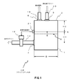
- the present invention is applied to a flash vessel 10 having a structure as shown in FIG.
- the flash vessel 10 is a flash vessel in a high pressure acid leaching process in which a raw material slurry is leached in an autoclave under high temperature and high pressure, and then the leached slurry is cooled down to room temperature and normal pressure. And a slurry charging port 3 and a steam discharge port 5 are provided in the ceiling portion 2 where the upper portion of the barrel portion 1 is closed, and a slurry discharge port 4 is provided in the barrel portion 1.
- the slurry charging inlet 3 is connected to a slurry charging pipe 13 for charging the leached slurry, which has been lowered to a predetermined temperature and a predetermined pressure, into the flash vessel 10.
- a slurry discharge pipe 14 for discharging the slurry charged in the flash vessel 10 is connected, and the steam generated in the flash vessel 10 as the slurry is charged is collected in the vapor outlet 5.
- a steam discharge pipe 15 is connected.
- a slurry discharge valve 16 is installed in the slurry discharge pipe 14 connected to the slurry discharge port 4.
- the leached slurry lowered to a predetermined temperature and a predetermined pressure is charged through the slurry charging port 3, and the slurry charged in the flash vessel 10 is loaded into the slurry discharge port 4. Further, the steam generated from the charging of the slurry is discharged from the steam discharge port 5.
- the flash vessel 10 has a height H1 from the slurry discharge port 4 to the management liquid level position S, a height H2 from the management liquid level position S to the top of the flash vessel column, and a diameter of the flash vessel 10.
- D 0.35D ⁇ H1 ⁇ 0.45D 0.75D ⁇ H2 ⁇ 0.85D As at least one liquid level sensor 21 that detects the slurry liquid level 8 at the management liquid level position S is provided.
- the liquid level in the flash vessel 10 is set to an appropriate level by controlling the valve opening degree of the slurry discharge valve 16 according to the liquid level measurement result by the liquid level sensor 21. Kept.
- the flash vessel 10 is a flash vessel in a high-pressure acid leaching process in which the raw slurry is leached in an autoclave under high temperature and high pressure, and then the leached slurry is cooled down to room temperature and normal pressure.
- the flash vessel 10 is operated as follows.
- the height from the slurry discharge port 4 to the management liquid level position S is H1
- the height from the management liquid level position to the top of the flash vessel column is H2
- the diameter of the flash vessel 10 is D.
- at least one liquid level sensor 21 detects the slurry liquid level 8 at the management liquid level position S, and lifts the slurry discharge valve 16 installed on the slurry discharge pipe 14 led out from the flash vessel 10.
- the slurry level 8 is opened when the liquid level sensor 21 detects it, and is closed when the level sensor 21 detects the falling slurry level 8.
- the slurry liquid level in the flash vessel 10 can be controlled within an appropriate range. That is, the situation where the steam flows into the slurry discharge pipe 14 side is less likely to occur, thereby reducing the problem of damage to the slurry discharge valve 16.
- the raw material slurry is nickel oxide ore slurry
- this flash vessel 10 the leached slurry obtained by leaching the nickel oxide ore slurry with sulfuric acid is charged, and the charged slurry is cooled to room temperature and normal pressure.
- the slurry liquid level 8 is detected by the liquid level sensor 21 at the management liquid level position S, and the slurry discharge installed on the slurry discharge pipe 14 led out from the flash vessel 10.
- the valve 16 is opened when the liquid level sensor 21 detects the rising slurry liquid level 8 and is closed when the liquid level sensor 21 detects the falling slurry liquid level 21. No need for skilled workers who can detect the liquid level inside.
- the liquid level sensor 21 is not particularly limited except that an appropriate detection signal is transmitted. However, the liquid level sensor 21 provided at the control liquid level position S of the flash vessel 10 has risen. If a signal for opening the valve is sent to the slurry discharge valve 16 when a surface is detected, and a signal for closing the valve is sent to the slurry discharge valve 16 when a descending liquid level is detected, the operation is performed. This is preferable because it can be automated.
- the raw material slurry is not particularly limited, and raw materials containing various metal compounds used when leaching a desired metal by a high pressure acid leaching method, for example, metals, sulfides, oxides, For example, ore slurry made of nickel oxide ore is preferable.
- the high pressure acid leaching step is not particularly limited, but in addition to an autoclave and a flash vessel, a preheater that raises and raises the temperature of the ore slurry employed in a general high pressure acid leaching method stepwise. Is included.
- the autoclave is not particularly limited, and a vertical or horizontal pressure vessel heated by blowing external air or pressurized steam is used.
- the lash vessel 10 is not particularly limited, and a multistage type is used.
- the pre-heater is not particularly limited, but a multistage counter-current direct heating heat exchanger is used. At this time, water vapor is used as a heating medium.
- the steam generated by a general method such as a boiler may be used as the steam, but the steam generated in the flash vessel that gradually cools and depressurizes the leach slurry discharged from the autoclave is recovered. It is preferable to circulate and use.
- the high pressure acid leaching method of the nickel oxide ore includes ore processing step P1, high pressure acid leaching step P2, solid-liquid separation step P3, neutralization step P4, dezincification step P5 and nickel / cobalt sulfide.
- Process P6 is included.
- step P1 large blocks, gangue, tree roots, and the like are removed from the nickel oxide ore to prepare an ore slurry having a predetermined slurry concentration.
- the ore slurry transferred from the ore processing step is preheated with a preheater, and the preheated ore slurry is leached with sulfuric acid under high temperature and high pressure while blowing high pressure air and high pressure steam.
- the temperature and pressure of the high temperature and high pressure leaching slurry are lowered by the flash vessel 10.
- the leaching slurry is subjected to solid-liquid separation to obtain a leaching solution and a leaching residue.
- a nickel / cobalt mixed sulfide is obtained from the leachate by a sulfide precipitation method.
- the nickel oxide ore is mainly a so-called laterite ore such as limonite or saprolite ore.
- the nickel content of the laterite ore is usually 0.5 to 2.0% by mass, and is contained as a hydroxide or siliceous clay (magnesium silicate) mineral.
- the iron content is 20 to 50% by mass and is mainly in the form of trivalent hydroxide (goethite, FeOOH), but partly divalent iron is contained in the siliceous clay. .
- the slurry concentration of the ore slurry produced in the ore treatment step P1 is not particularly limited because it depends greatly on the properties of the nickel oxide ore to be treated.
- the higher the slurry concentration of the leaching slurry Preferably, it is usually adjusted to 20 to 50% by mass. That is, when the slurry concentration of the leaching slurry is less than 20% by mass, a large facility is required to obtain the same residence time in each step including the leaching step, and the amount of acid added also increases to adjust the residual acid concentration. .
- the nickel concentration of the obtained leachate becomes low, which ultimately causes a decrease in the actual yield.
- Examples of practical equipment for the high-pressure acid leaching step P2 include, for example, a three-stage preheater, an autoclave, and a three-stage flash vessel.
- a cylindrical container having a flash vessel 10 with a diameter of about 4 to 6 m and a height of about 10 to 12 m is installed vertically.
- the slurry introduced into the first-stage flash vessel is, for example, 200 to 270 ° C., and the pressure is, for example, 1.8 to 5.8 MPaG.
- the flash vessel 10 used in the high pressure acid leaching step P2 is operated as follows, for example.
- the diameter D of the flash vessel 10 is 5.0 m
- the height H1 from the slurry discharge port 4 to the management liquid level position S is: 0.35D ⁇ H1 ⁇ 0.45D
- the height H2 from the control liquid level S to the top of the flash vessel tower is 0.75D ⁇ H2 ⁇ 0.85D It is set to 4.0 m that satisfies the following condition.
- the liquid level sensor 21 detects the liquid level 8 at the liquid level position S, and the liquid level sensor 21 is connected to the slurry discharge valve 16 installed on the slurry discharge pipe 14 led out from the flash vessel 10. Is opened when the slurry liquid level 8 rising is detected, and closed when the liquid level sensor 21 detects the falling slurry liquid level 8.
- Example 1 A practical plant for nickel oxide ore, including examples of practical equipment for the high-pressure acid leaching process described above, was used.
- the leaching slurry prepared by adjusting the ore slurry shown in Table 1 to about 245 ° C. and about 4 MPaG at the outlet of the autoclave is charged into the first-stage flash vessel, and then sequentially into the second-stage and third-stage flash vessels.
- the operation of transferring and lowering the leach slurry to normal pressure was carried out for 6 months.
- Example 1 The same operation as in Example 1 was performed with a conventional facility that does not have a hydrostatic tower, instead of the practical facility example of the high-pressure acid leaching process described above.
- the height from the slurry discharge port 4 to the management liquid level position S is H1
- the height from the management liquid level position S to the top of the flash vessel column is H1.
- the diameter of the flash vessel is D, 0.35D ⁇ H1 ⁇ 0.45D 0.75D ⁇ H2 ⁇ 0.85D
- the single liquid level sensor 21 detects the slurry liquid level 8 at the control liquid level position S, and the slurry discharge valve 16 installed on the slurry discharge pipe 14 led out from the flash vessel 10 is raised.
- the slurry liquid level 8 is opened when the liquid level sensor 21 detects it and closed when the liquid level sensor 21 detects the descending slurry liquid level 8.
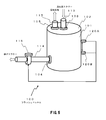
- the flash shown in FIG. As in the vessel 10A, the position above the control liquid level position S by 0.3D to 0.4D, for example, is the slurry upper limit position Ha, and from the control liquid level position S by only 0.2D to 0.3D, for example.
- the lower position is defined as the slurry lower limit position Hb, and the slurry liquid is respectively detected by the liquid level sensor at the slurry upper limit position Ha and the slurry lower limit position Hb. 8, and when the liquid level sensor 21 ⁇ / b> A detects the rising slurry liquid level 8 at the slurry upper limit position Ha, the slurry discharge valve 16 installed on the slurry discharge pipe 14 led out from the flash vessel 10 is detected.
- the slurry liquid level 8 that has fallen down may be closed when the liquid level sensor 21B detects it at the slurry lower limit position Hb.
- the flash vessel 10A shown in FIG. 3 is provided with two liquid level sensors 21A and 21B in the flash vessel 10 shown in FIG. 1, and the same components are denoted by the same reference numerals, Detailed description is omitted.
- the slurry liquid level 8 is detected by the liquid level sensors 21A and 21B at the slurry upper limit position Ha and the slurry lower limit position Hb set above and below the management liquid level position S, and the slurry discharge valve 16 is controlled to be opened and closed.
- the slurry liquid level in the flash vessel 10A can be stably controlled within an appropriate range.
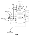
- a hydrostatic tower 20 having a lower portion communicating with the liquid phase space in the flash vessel 10B and an upper portion communicating with the gas phase space is provided. Is detected by at least one upper limit liquid level sensor 21A installed at the same level as the management liquid level position S, and the slurry discharge valve 16 installed on the slurry discharge pipe led out from the flash vessel is The liquid level in the still water tower 20 that has risen is opened when the liquid level sensor 21A detects the liquid level, and the liquid level in the still water tower 20 that has been lowered is closed when the lower limit liquid level sensor 21B detects it. You may do it.
- the flash vessel 10B shown in FIG. 4 is provided with a hydrostatic tower 20 including two liquid level sensors 21A and 21B in the flash vessel 10A shown in FIG. 3, and the same components are denoted by the same reference numerals. A detailed description thereof will be omitted.
- the flash vessel 10B shown in FIG. 4 includes a hydrostatic tower 20 having a lower portion communicating with a liquid phase space in the flash vessel 10B and an upper portion communicating with a gas phase space.
- the lower part of the hydrostatic tower 20 is connected to an arbitrary position on the slurry discharge pipe 14 from the connection point with the flash vessel 10B to the slurry discharge valve 16, and the lower part of the hydrostatic tower 20 is connected to the steam discharge pipe 15.
- the upper part of the hydrostatic tower 20 is connected to an arbitrary position above.
- the lower part of the hydrostatic tower 20 having a diameter of 250 mm is connected to a position where the slurry is connected to the flash vessel 10B on the slurry discharge pipe 14 and an intermediate position (position about 50 cm from the connection position) between the slurry discharge valve 16 and steam.
- the upper part of the water tower 20 having a diameter of 250 mm was connected to a position of about 50 cm from the connection point with the flash vessel 10 on the discharge pipe 15.
- an upper limit liquid level sensor 21A is installed at the same level as the slurry upper limit position Ha
- a lower limit liquid level sensor 21B is installed at the same level as the slurry lower limit position Hb. did.
- the diameter of the hydrostatic tower 20 is 250 mm
- the diameter D of the main body of the flash vessel 10B is about 5 m, which is 1/20 of the diameter.
- the diameter of the hydrostatic tower 20 is not particularly limited, but the diameter A of the hydrostatic tower 20 is 1/100 ⁇ B ⁇ A ⁇ 1/5 compared with the diameter B of the main body of the flash vessel 10B. A range is preferable. If it is too wide, there is a concern that the investment cost will increase and the slurry will stay in the hydrostatic tower 20, and if it is too narrow, it will be susceptible to the fluctuation of the liquid level, and the slurry may be easily clogged by the slurry.
- the hydrostatic tower 20 is installed at the same level as the predetermined liquid level upper limit of the liquid phase space and detects at least one upper liquid level sensor 21A for detecting the rising liquid level in the hydrostatic tower 20. And at least one lower limit liquid level sensor 21B for detecting the liquid level in the still water tower 20 which is installed at the same level as the predetermined lower limit of the liquid level in the liquid phase space.
- the valve opening degree of the slurry discharge valve 16 is controlled in accordance with the liquid level measurement result by the liquid level sensors 21A and 21B provided in the hydrostatic tower 20, so that the inside of the flash vessel 10 The liquid level is maintained at an appropriate level.
- the flash vessel 10B is a flash vessel in a high pressure acid leaching process in which the raw slurry is leached under high temperature and high pressure by an autoclave, and then the temperature of the leached slurry is lowered to normal temperature and pressure, and is operated as follows.
- the valve is turned on when the upper liquid level sensor 21A detects the rising liquid level.
- a signal for opening is sent to the slurry discharge valve 16, and the slurry discharge valve 16 is opened, thereby transferring the slurry in the flash vessel 10B to the next step.
- the slurry liquid level in the flash vessel 10B is lowered, and when the lower liquid level sensor 21B detects the lowered liquid level, the slurry is discharged.
- the slurry liquid level in the flash vessel 10 starts to rise again. By repeating this procedure, operation can be performed continuously.
- the level of the slurry liquid in the flash vessel 10B can be more stably controlled to an appropriate range, and the situation where steam flows into the slurry discharge pipe 14 side is less likely to occur, thereby The problem of damage to the slurry discharge valve 16 is reduced.
Abstract
Description
0.35D≦H1≦0.45D
0.75D≦H2≦0.85D
として、上記管理液面位置において、少なくとも1つの液面センサーにより、スラリー液面を検出し、上記フラッシュベッセルから導出されたスラリー排出管上に設置されたスラリー排出バルブを、上昇してきたスラリー液面を上記液面センサーが検知した際に開放し、降下してきたスラリー液面を上記液面センサーが検知した際に閉鎖することを特徴とする。 That is, the present invention is a flash vessel operating method in a high-pressure acid leaching process including a flash vessel in which raw slurry is leached under high temperature and high pressure in an autoclave, and then the leached slurry is cooled to room temperature and normal pressure. When the height from the discharge port to the management liquid level position is H1, the height from the management liquid level position to the top of the flash vessel tower is H2, and the diameter of the flash vessel is D,
0.35D ≦ H1 ≦ 0.45D
0.75D ≦ H2 ≦ 0.85D
As the slurry liquid level, the slurry liquid level detected by the at least one liquid level sensor at the management liquid level position and the slurry discharge valve installed on the slurry discharge pipe led out from the flash vessel is raised. Is opened when the liquid level sensor detects, and when the liquid level sensor detects the falling slurry liquid level, the liquid level sensor is closed.
0.35D≦H1≦0.45D
0.75D≦H2≦0.85D
として、上記管理液面位置Sにおいてスラリー液面8を検出する少なくとも1つの液面センサー21を備える。 The
0.35D ≦ H1 ≦ 0.45D
0.75D ≦ H2 ≦ 0.85D
As at least one
0.35D≦H1≦0.45D
0.75D≦H2≦0.85D
として、少なくとも1つの液面センサー21により、上記管理液面位置Sにおいてスラリー液面8を検出し、上記フラッシュベッセル10から導出されたスラリー排出管14上に設置されたスラリー排出バルブ16を、上昇してきたスラリー液面8を上記液面センサー21が検知した際に開放し、降下してきたスラリー液面8を上記液面センサー21が検知した際に閉鎖する。 That is, in this
0.35D ≦ H1 ≦ 0.45D
0.75D ≦ H2 ≦ 0.85D
As a result, at least one
0.35D≦H1≦0.45D
なる条件を満たす2.0mにされており、また、上記管理液面位置Sからフラッシュベッセル塔頂までの高さH2は、
0.75D≦H2≦0.85D
なる条件を満たす4.0mにされている。 That is, the diameter D of the
0.35D ≦ H1 ≦ 0.45D
The height H2 from the control liquid level S to the top of the flash vessel tower is
0.75D ≦ H2 ≦ 0.85D
It is set to 4.0 m that satisfies the following condition.

前述した高圧酸浸出工程の実用設備例を含む、ニッケル酸化鉱石の実用プラントを用いた。 Example 1
A practical plant for nickel oxide ore, including examples of practical equipment for the high-pressure acid leaching process described above, was used.
前述した高圧酸浸出工程の実用設備例ではなく、静水塔を備えない従来の設備で実施例1と同様の操業を行なった。 (Comparative Example 1)
The same operation as in Example 1 was performed with a conventional facility that does not have a hydrostatic tower, instead of the practical facility example of the high-pressure acid leaching process described above.
0.35D≦H1≦0.45D
0.75D≦H2≦0.85D
として、1つの液面センサー21により、上記管理液面位置Sにおいてスラリー液面8を検出し、上記フラッシュベッセル10から導出されたスラリー排出管14上に設置されたスラリー排出バルブ16を、上昇してきたスラリー液面8を上記液面センサー21が検知した際に開放し、降下してきたスラリー液面8を上記液面センサー21が検知した際に閉鎖するようにしたが、例えば図3に示すフラッシュベッセル10Aのように、上記管理液面位置Sから例えば0.3D~0.4Dだけ上方の位置をスラリー上限位置Haとし、また、上記管理液面位置Sから例えば0.2D~0.3Dだけ下方の位置をスラリー下限位置Hbとして、上記スラリー上限位置Haとスラリー下限位置Hbにおいて、それぞれ液面センサーによりスラリー液面8を検出し、上記フラッシュベッセル10から導出されたスラリー排出管14上に設置されたスラリー排出バルブ16を、上昇してきたスラリー液面8を上記スラリー上限位置Haにおいて液面センサー21Aが検知した際に開放し、降下してきたスラリー液面8をスラリー下限位置Hbにおいて上記液面センサー21Bが検知した際に閉鎖するようにしてもよい。 Here, in the embodiment of the operation method of the
0.35D ≦ H1 ≦ 0.45D
0.75D ≦ H2 ≦ 0.85D
As a result, the single
Claims (3)
- 原料スラリーをオートクレーブで高温高圧下に浸出し、次いで浸出後のスラリーを常温常圧まで降温降圧するフラッシュベッセルを含む高圧酸浸出工程におけるフラッシュベッセルの運転方法であって、
スラリー排出口から管理液面位置までの高さをH1、上記管理液面位置からフラッシュベッセル塔頂までの高さをH2、フラッシュベッセルの直径をDとした時に、
0.35D≦H1≦0.45D
0.75D≦H2≦0.85D
として、上記管理液面位置において、少なくとも1つの液面センサーにより、スラリー液面を検出し、
上記フラッシュベッセルから導出されたスラリー排出管上に設置されたスラリー排出バルブを、上昇してきたスラリー液面を上記液位センサーが検知した際に開放し、降下してきたスラリー液面を上記液面センサーが検知した際に閉鎖することを特徴とするフラッシュベッセルの運転方法。 A method for operating a flash vessel in a high-pressure acid leaching process including a flash vessel for leaching a raw material slurry under high temperature and high pressure in an autoclave, and then lowering and lowering the temperature of the leached slurry to room temperature and normal pressure,
When the height from the slurry discharge port to the management liquid level position is H1, the height from the management liquid level position to the top of the flash vessel tower is H2, and the diameter of the flash vessel is D,
0.35D ≦ H1 ≦ 0.45D
0.75D ≦ H2 ≦ 0.85D
As described above, at the management liquid level position, the slurry liquid level is detected by at least one liquid level sensor,
The slurry discharge valve installed on the slurry discharge pipe led out from the flash vessel is opened when the rising liquid level of the slurry is detected by the liquid level sensor, and the lowered liquid level of the slurry is detected by the liquid level sensor. A method of operating a flash vessel, which is closed when detected. - 上記フラッシュベッセル内の液相空間に下部が連通され、気相空間に上部が連通された静水塔内の液面を、上記管理液面位置と同水準の位置に設置された少なくとも1つの液位センサーにより検出し、
上記フラッシュベッセルから導出されたスラリー排出管上に設置されたスラリー排出バルブを、上昇してきた上記静水塔内の液面を上記液面センサーが検知した際に開放し、降下してきた上記静水塔内の液面を上記液面センサーが検知した際に閉鎖することを特徴とする請求項1記載のフラッシュベッセルの運転方法。 At least one liquid level installed at the same level as the control liquid level in the liquid level in the still water tower whose lower part is connected to the liquid phase space in the flash vessel and whose upper part is connected to the gas phase space. Detected by the sensor,
The slurry discharge valve installed on the slurry discharge pipe led out from the flash vessel is opened when the liquid level sensor detects the liquid level in the rising still water tower, and the inside of the still water tower has been lowered. 2. The method of operating a flash vessel according to claim 1, wherein the liquid level is closed when detected by the liquid level sensor. - 上記原料スラリーはニッケル酸化鉱石スラリーであり、該ニッケル酸化鉱石スラリーを硫酸で浸出した浸出後のスラリーを常温常圧まで降温降圧することを特徴とする請求項1又は請求項2に記載のフラッシュベッセルの運転方法。 The flash vessel according to claim 1 or 2, wherein the raw material slurry is a nickel oxide ore slurry, and the temperature of the leached slurry obtained by leaching the nickel oxide ore slurry with sulfuric acid is lowered to normal temperature and pressure. Driving method.
Priority Applications (7)
| Application Number | Priority Date | Filing Date | Title |
|---|---|---|---|
| AU2012365088A AU2012365088B2 (en) | 2012-01-13 | 2012-12-27 | Method for operating flash vessel |
| CA2862800A CA2862800A1 (en) | 2012-01-13 | 2012-12-27 | Method for operating flash vessel |
| JP2013528452A JP5482970B2 (en) | 2012-01-13 | 2012-12-27 | How to operate the flash vessel |
| CN201280066736.8A CN104039992B (en) | 2012-01-13 | 2012-12-27 | The method of operation of flasher |
| US14/370,841 US9896740B2 (en) | 2012-01-13 | 2012-12-27 | Method for operating flash vessel |
| EP12864964.7A EP2803738B1 (en) | 2012-01-13 | 2012-12-27 | Method for operating flash vessel |
| PH12014501593A PH12014501593A1 (en) | 2012-01-13 | 2014-07-10 | Method for operating flash vessel |
Applications Claiming Priority (2)
| Application Number | Priority Date | Filing Date | Title |
|---|---|---|---|
| JP2012-005441 | 2012-01-13 | ||
| JP2012005441 | 2012-01-13 |
Publications (1)
| Publication Number | Publication Date |
|---|---|
| WO2013105453A1 true WO2013105453A1 (en) | 2013-07-18 |
Family
ID=48781409
Family Applications (1)
| Application Number | Title | Priority Date | Filing Date |
|---|---|---|---|
| PCT/JP2012/083947 WO2013105453A1 (en) | 2012-01-13 | 2012-12-27 | Method for operating flash vessel |
Country Status (8)
| Country | Link |
|---|---|
| US (1) | US9896740B2 (en) |
| EP (1) | EP2803738B1 (en) |
| JP (2) | JP5482970B2 (en) |
| CN (1) | CN104039992B (en) |
| AU (1) | AU2012365088B2 (en) |
| CA (1) | CA2862800A1 (en) |
| PH (1) | PH12014501593A1 (en) |
| WO (1) | WO2013105453A1 (en) |
Cited By (2)
| Publication number | Priority date | Publication date | Assignee | Title |
|---|---|---|---|---|
| JP2016003360A (en) * | 2014-06-17 | 2016-01-12 | 住友金属鉱山株式会社 | Production method of nickel sulfate solution |
| US11001507B2 (en) | 2018-02-01 | 2021-05-11 | Korea Zinc Co., Ltd. | Method of recovering iron from zinc sulphate solution |
Families Citing this family (2)
| Publication number | Priority date | Publication date | Assignee | Title |
|---|---|---|---|---|
| EP2803739B1 (en) * | 2012-01-13 | 2018-03-14 | Sumitomo Metal Mining Co., Ltd. | Flash vessel and method for operating same |
| JP6661936B2 (en) * | 2015-09-25 | 2020-03-11 | 住友金属鉱山株式会社 | Nickel oxide ore hydro smelting method, leaching equipment |
Citations (5)
| Publication number | Priority date | Publication date | Assignee | Title |
|---|---|---|---|---|
| JPH1080700A (en) | 1996-05-31 | 1998-03-31 | Takeo Terada | Method for producing concentrated solution from organic sludge slurry solution and treatment of organic sludge |
| JP2009524797A (en) | 2006-09-29 | 2009-07-02 | キャリア コーポレイション | Refrigerant vapor compression system with flash tank receiver |
| JP2010031341A (en) * | 2008-07-31 | 2010-02-12 | Sumitomo Metal Mining Co Ltd | Hydrometallurgical process for nickel oxide ore |
| JP2010059489A (en) | 2008-09-04 | 2010-03-18 | Sumitomo Metal Mining Co Ltd | Pressure adjustment method for autoclave |
| JP2010164223A (en) * | 2009-01-14 | 2010-07-29 | Kobe Steel Ltd | Steam generator |
Family Cites Families (5)
| Publication number | Priority date | Publication date | Assignee | Title |
|---|---|---|---|---|
| US5052426A (en) * | 1991-01-16 | 1991-10-01 | The United States Of America As Represented By The United States Department Of Energy | System for pressure letdown of abrasive slurries |
| JPH09218072A (en) * | 1996-02-13 | 1997-08-19 | Yamaha Motor Co Ltd | Liquid level sensor |
| EP1330555A4 (en) * | 2000-09-15 | 2005-08-31 | Commw Scient Ind Res Org | Solvent extraction process for recovering nickel and cobalt from leach solutions |
| CN100417629C (en) * | 2006-04-13 | 2008-09-10 | 四川大学 | Phosphor ammonium slurry reaction-concentration evaporator disposal method |
| AU2009353875B2 (en) * | 2009-10-08 | 2014-02-06 | Hatch Ltd. | Flash tube and flash vessel configuration for pressure letdown |
-
2012
- 2012-12-27 JP JP2013528452A patent/JP5482970B2/en active Active
- 2012-12-27 CA CA2862800A patent/CA2862800A1/en not_active Abandoned
- 2012-12-27 EP EP12864964.7A patent/EP2803738B1/en not_active Not-in-force
- 2012-12-27 CN CN201280066736.8A patent/CN104039992B/en not_active Expired - Fee Related
- 2012-12-27 AU AU2012365088A patent/AU2012365088B2/en active Active
- 2012-12-27 WO PCT/JP2012/083947 patent/WO2013105453A1/en active Application Filing
- 2012-12-27 US US14/370,841 patent/US9896740B2/en not_active Expired - Fee Related
-
2014
- 2014-02-03 JP JP2014018327A patent/JP5534121B1/en active Active
- 2014-07-10 PH PH12014501593A patent/PH12014501593A1/en unknown
Patent Citations (5)
| Publication number | Priority date | Publication date | Assignee | Title |
|---|---|---|---|---|
| JPH1080700A (en) | 1996-05-31 | 1998-03-31 | Takeo Terada | Method for producing concentrated solution from organic sludge slurry solution and treatment of organic sludge |
| JP2009524797A (en) | 2006-09-29 | 2009-07-02 | キャリア コーポレイション | Refrigerant vapor compression system with flash tank receiver |
| JP2010031341A (en) * | 2008-07-31 | 2010-02-12 | Sumitomo Metal Mining Co Ltd | Hydrometallurgical process for nickel oxide ore |
| JP2010059489A (en) | 2008-09-04 | 2010-03-18 | Sumitomo Metal Mining Co Ltd | Pressure adjustment method for autoclave |
| JP2010164223A (en) * | 2009-01-14 | 2010-07-29 | Kobe Steel Ltd | Steam generator |
Non-Patent Citations (1)
| Title |
|---|
| See also references of EP2803738A4 |
Cited By (2)
| Publication number | Priority date | Publication date | Assignee | Title |
|---|---|---|---|---|
| JP2016003360A (en) * | 2014-06-17 | 2016-01-12 | 住友金属鉱山株式会社 | Production method of nickel sulfate solution |
| US11001507B2 (en) | 2018-02-01 | 2021-05-11 | Korea Zinc Co., Ltd. | Method of recovering iron from zinc sulphate solution |
Also Published As
| Publication number | Publication date |
|---|---|
| EP2803738B1 (en) | 2019-04-17 |
| AU2012365088B2 (en) | 2016-11-03 |
| AU2012365088A1 (en) | 2014-07-31 |
| PH12014501593B1 (en) | 2014-10-08 |
| CA2862800A1 (en) | 2013-07-18 |
| JP5534121B1 (en) | 2014-06-25 |
| CN104039992A (en) | 2014-09-10 |
| US20150044112A1 (en) | 2015-02-12 |
| JPWO2013105453A1 (en) | 2015-05-11 |
| JP5482970B2 (en) | 2014-05-07 |
| PH12014501593A1 (en) | 2014-10-08 |
| EP2803738A1 (en) | 2014-11-19 |
| US9896740B2 (en) | 2018-02-20 |
| CN104039992B (en) | 2016-04-06 |
| EP2803738A4 (en) | 2015-07-15 |
| JP2014148751A (en) | 2014-08-21 |
Similar Documents
| Publication | Publication Date | Title |
|---|---|---|
| JP5768918B2 (en) | How to operate the flash vessel | |
| JP5332418B2 (en) | Autoclave pressure adjustment method | |
| JP5287010B2 (en) | Method for hydrometallizing nickel oxide ore | |
| JP6135609B2 (en) | How to blow gas into the autoclave | |
| JP5534121B1 (en) | How to operate the flash vessel | |
| JP6799160B2 (en) | How to recover iron from zinc sulphate solution | |
| AU2016330874B2 (en) | Method for manufacturing nickel powder, and method for operating reaction facility | |
| JP2019214010A (en) | Clogging prevention method of transfer piping system of nickel oxide ore slurry | |
| JP7298126B2 (en) | Nickel Oxide Ore Autoclave Equipment | |
| EP3394301B1 (en) | Removal of gypsum from leach solution | |
| JP7226181B2 (en) | Hydrogen sulfide gas abatement equipment | |
| JP7230699B2 (en) | Seal water supply device for shaft sealing of stirrer of high-temperature and high-pressure vessel | |
| CN117083397A (en) | System and method for regulating and controlling Al precipitation amount in high-pressure acid leaching process of laterite-nickel ore | |
| JP2020132945A (en) | Sulfurization apparatus, and operation method thereof |
Legal Events
| Date | Code | Title | Description |
|---|---|---|---|
| WWE | Wipo information: entry into national phase |
Ref document number: 201280066736.8 Country of ref document: CN |
|
| ENP | Entry into the national phase |
Ref document number: 2013528452 Country of ref document: JP Kind code of ref document: A |
|
| 121 | Ep: the epo has been informed by wipo that ep was designated in this application |
Ref document number: 12864964 Country of ref document: EP Kind code of ref document: A1 |
|
| DPE1 | Request for preliminary examination filed after expiration of 19th month from priority date (pct application filed from 20040101) | ||
| WWE | Wipo information: entry into national phase |
Ref document number: 14370841 Country of ref document: US |
|
| ENP | Entry into the national phase |
Ref document number: 2862800 Country of ref document: CA |
|
| WWE | Wipo information: entry into national phase |
Ref document number: 12014501593 Country of ref document: PH |
|
| ENP | Entry into the national phase |
Ref document number: 2012365088 Country of ref document: AU Date of ref document: 20121227 Kind code of ref document: A |
|
| WWE | Wipo information: entry into national phase |
Ref document number: 2012864964 Country of ref document: EP |
|
| NENP | Non-entry into the national phase |
Ref country code: DE |