WO2013105367A1 - 画像データの復号方法、画像データの復号装置、画像データの符号化方法、及び画像データの符号化装置 - Google Patents
画像データの復号方法、画像データの復号装置、画像データの符号化方法、及び画像データの符号化装置 Download PDFInfo
- Publication number
- WO2013105367A1 WO2013105367A1 PCT/JP2012/081630 JP2012081630W WO2013105367A1 WO 2013105367 A1 WO2013105367 A1 WO 2013105367A1 JP 2012081630 W JP2012081630 W JP 2012081630W WO 2013105367 A1 WO2013105367 A1 WO 2013105367A1
- Authority
- WO
- WIPO (PCT)
- Prior art keywords
- transform
- frequency conversion
- inverse
- prediction
- information
- Prior art date
- Legal status (The legal status is an assumption and is not a legal conclusion. Google has not performed a legal analysis and makes no representation as to the accuracy of the status listed.)
- Ceased
Links
Images






Classifications
-
- H—ELECTRICITY
- H04—ELECTRIC COMMUNICATION TECHNIQUE
- H04N—PICTORIAL COMMUNICATION, e.g. TELEVISION
- H04N19/00—Methods or arrangements for coding, decoding, compressing or decompressing digital video signals
- H04N19/10—Methods or arrangements for coding, decoding, compressing or decompressing digital video signals using adaptive coding
- H04N19/102—Methods or arrangements for coding, decoding, compressing or decompressing digital video signals using adaptive coding characterised by the element, parameter or selection affected or controlled by the adaptive coding
- H04N19/12—Selection from among a plurality of transforms or standards, e.g. selection between discrete cosine transform [DCT] and sub-band transform or selection between H.263 and H.264
-
- H—ELECTRICITY
- H04—ELECTRIC COMMUNICATION TECHNIQUE
- H04N—PICTORIAL COMMUNICATION, e.g. TELEVISION
- H04N19/00—Methods or arrangements for coding, decoding, compressing or decompressing digital video signals
- H04N19/10—Methods or arrangements for coding, decoding, compressing or decompressing digital video signals using adaptive coding
- H04N19/134—Methods or arrangements for coding, decoding, compressing or decompressing digital video signals using adaptive coding characterised by the element, parameter or criterion affecting or controlling the adaptive coding
- H04N19/136—Incoming video signal characteristics or properties
- H04N19/137—Motion inside a coding unit, e.g. average field, frame or block difference
- H04N19/139—Analysis of motion vectors, e.g. their magnitude, direction, variance or reliability
-
- H—ELECTRICITY
- H04—ELECTRIC COMMUNICATION TECHNIQUE
- H04N—PICTORIAL COMMUNICATION, e.g. TELEVISION
- H04N19/00—Methods or arrangements for coding, decoding, compressing or decompressing digital video signals
- H04N19/10—Methods or arrangements for coding, decoding, compressing or decompressing digital video signals using adaptive coding
- H04N19/134—Methods or arrangements for coding, decoding, compressing or decompressing digital video signals using adaptive coding characterised by the element, parameter or criterion affecting or controlling the adaptive coding
- H04N19/157—Assigned coding mode, i.e. the coding mode being predefined or preselected to be further used for selection of another element or parameter
- H04N19/159—Prediction type, e.g. intra-frame, inter-frame or bidirectional frame prediction
-
- H—ELECTRICITY
- H04—ELECTRIC COMMUNICATION TECHNIQUE
- H04N—PICTORIAL COMMUNICATION, e.g. TELEVISION
- H04N19/00—Methods or arrangements for coding, decoding, compressing or decompressing digital video signals
- H04N19/10—Methods or arrangements for coding, decoding, compressing or decompressing digital video signals using adaptive coding
- H04N19/169—Methods or arrangements for coding, decoding, compressing or decompressing digital video signals using adaptive coding characterised by the coding unit, i.e. the structural portion or semantic portion of the video signal being the object or the subject of the adaptive coding
- H04N19/17—Methods or arrangements for coding, decoding, compressing or decompressing digital video signals using adaptive coding characterised by the coding unit, i.e. the structural portion or semantic portion of the video signal being the object or the subject of the adaptive coding the unit being an image region, e.g. an object
- H04N19/176—Methods or arrangements for coding, decoding, compressing or decompressing digital video signals using adaptive coding characterised by the coding unit, i.e. the structural portion or semantic portion of the video signal being the object or the subject of the adaptive coding the unit being an image region, e.g. an object the region being a block, e.g. a macroblock
Definitions
- the present invention relates to a decoding method, a decoding device, an encoding method, and an encoding device for moving image data, and more particularly to frequency conversion in intra prediction, for example, a mobile phone, a navigation system, a DVD / HDD / BD recorder.
- the present invention relates to a technology that is effective when applied to an apparatus that performs moving image encoding / decoding, such as a digital video camera, a digital camera, a digital TV, and a telephone conference system.
- H.264 standardized by MPEG (Moving Picture Experts Group), ITU-T (International Telecommunication Union, Telecommunication standardization sector), etc.
- An encoding method represented by the H.264 standard is widely used.
- predictive encoding is employed to reduce the code amount.
- a difference between an image (predicted image) predicted by a certain method and the original image is encoded.
- a decoded image is obtained by adding a difference to the predicted image.
- Patent Document 1 for generating a predicted image.
- a predicted image is generated by designating a reference position in the same screen by a vector. Further, an unprocessed region (unprocessed region) is obtained by interpolating a region included in the reference range that has not yet been encoded / decoded (hereinafter referred to as an unencoded / decoded region) using a multiplication vector such as a prediction vector. A decrease in encoding efficiency when a range including a large amount of (encoding / decoding area) is referred to is suppressed.
- the difference between the predicted image and the original image is divided into blocks of N pixels ⁇ N lines (N is a natural number), DCT (Discrete Cosine Transform) or DST (Discrete Sine Transform: Frequency conversion such as discrete sine conversion is performed.
- N is a natural number
- DCT Discrete Cosine Transform
- DST Discrete Sine Transform: Frequency conversion such as discrete sine conversion is performed.
- the frequency conversion is described in H.264.
- processing is performed with integer precision that simplifies the processing by combining the quantization of the subsequent processing in units obtained by dividing an image into 4 pixels ⁇ 4 lines or units divided into 8 pixels ⁇ 8 lines. Since the error between the predicted image and the original image tends to be uniformly distributed, when DCT is performed, data concentrates on the upper left (low frequency) side of the matrix of calculation results.
- the pixel area data can be decoded by performing the inverse transformation.
- Patent Document 2 in view of the fact that frequency conversion in the horizontal and vertical directions is not necessarily optimal, conversion that does not depend on the prediction direction of the prediction mode and conversion that depends on the prediction mode are switched.
- the orthogonal transformation along is performed. If the prediction direction is diagonal, matrix conversion for frequency conversion is performed on the pixel columns in the block in the diagonal direction.
- Patent Document 3 describes an invention in which DCT and DST are selectively used according to the interpolation prediction direction. That is, a block that is predicted to be interpolated in the vertical direction uses DST in the vertical direction and DCT in the horizontal direction, and a block that is predicted to be interpolated in the horizontal direction is DST in the horizontal direction, depending on the prediction direction of the prediction block. In the vertical direction, encoding and decoding are performed using DCT.
- Patent Document 2 that performs orthogonal transformation along the prediction direction solves the data dispersion on the high frequency side in the repetitive portion copied corresponding to the unprocessed area. I can't.
- An object of the present invention is to realize high frequency conversion efficiency regardless of the existence form of the unprocessed area in the prediction block.
- a plurality of inverse frequency transform methods in which the bias position of the low frequency component of the frequency transform result differs according to the direction of the predicted block with respect to the processing target block and the degree of overlap for example, Inverse frequency transform is performed using a method selected from IDCT (Inverse Discrete Cosine Transform) and IDST (Inverse Discrete Sine Transform).
- IDCT Inverse Discrete Cosine Transform
- IDST Inverse Discrete Sine Transform
- a plurality of frequency conversion methods for example, DCT and DST, in which the bias positions of the low frequency components of the frequency conversion result are different depending on the direction of the prediction block with respect to the processing target block and the degree of overlap.
- Frequency conversion is performed using a method selected from The direction of the prediction block and the degree of overlap are equivalent to or correlated with the prediction vector.
- the overlapping part of the processing target block and the prediction block is an undecoded area / uncoded area. Since the portion is subjected to data interpolation and difference information is added or used to generate difference information, the inverse frequency conversion result / frequency conversion result for the difference information of that portion is dispersed into high frequency components. Depending on the size of the overlapping portion, the degree of dispersion of the frequency conversion result to the high frequency differs. In addition, the copy direction of data used for interpolation of the unprocessed portion is considered to correlate with the direction of the prediction block.
- the presence / absence and number of repetition patterns for interpolation depend on the direction and degree of overlap of the prediction block with respect to the processing target block, which is used for determining the conversion method, that is, the direction and size of the prediction vector. Therefore, by dynamically selecting a conversion method according to the direction of the prediction block with respect to the processing target block and the degree of overlap, for example, when the dispersion of the frequency conversion result in the high frequency in the DST increases, the low value in the DCT It is possible to obtain a relationship in which the value of the high frequency is large and the value of the high range is small.
- FIG. 1 is a block diagram illustrating an image data decoding apparatus according to an embodiment.
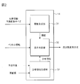
- FIG. 2 is a block diagram illustrating an example of the frequency conversion determination unit.
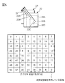
- FIG. 3 is an explanatory diagram illustrating a first example of the positional relationship between the reference position and the prediction block.
- FIG. 4 is an explanatory diagram illustrating a second example of the positional relationship between the reference position and the prediction block.
- FIG. 5 is an explanatory diagram showing a third example of the positional relationship between the reference position and the prediction block.
- 6 is an explanatory diagram illustrating a conversion method according to the size of the unprocessed area and the direction of the repeated pattern.
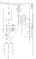
- FIG. 7 is a block diagram illustrating an image data encoding apparatus according to another embodiment.
- FIG. 7 is a block diagram illustrating an image data encoding apparatus according to another embodiment.
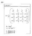
- FIG. 8 is an explanatory view illustrating a two-dimensional DCT transformation matrix and a matrix arithmetic expression.
- FIG. 9 is an explanatory diagram illustrating a two-dimensional DST conversion matrix and a matrix arithmetic expression.
- FIG. 10 is an explanatory diagram illustrating the distribution of pixel values in one dimension.
- FIG. 11 is a waveform diagram showing the result of one-dimensional DCT performed on the distribution of FIG.
- FIG. 12 is a waveform diagram showing the result of performing one-dimensional DST on the distribution of FIG.
- the image data decoding method includes the following processing.
- a data stream (10) including frequency conversion information subjected to frequency conversion and quantization on difference information between an image block and a prediction block and information for specifying the prediction block is input (11).
- processing. (13)
- the transform process is selected from a plurality of inverse frequency transform methods in which the bias position of the low frequency component of the frequency transform result is different according to the direction of the prediction block with respect to the decoding target block and the degree of overlap (14) Is used to perform inverse frequency conversion.
- the overlapping part of the decoding target block and the prediction block is an undecoded area. Since the portion is subjected to data interpolation and difference information is added, the result of DCT for the difference information of that portion is dispersed into high frequency components. Depending on the size of the overlapping portion, the degree of dispersion of the DCT result to the high frequency differs. In addition, the copy direction of data used for interpolation of the unprocessed portion is considered to correlate with the direction of the prediction block. In short, the presence / absence and number of repetition patterns for interpolation depend on the direction and degree of overlap of the prediction block with respect to the decoding target block, that is, the direction and size of the prediction vector, which are used for determining the conversion method.
- the variance of the frequency transform result in the high frequency in DST increases, and in DCT, the low frequency value is When the value of the high frequency is large and small, DCT inverse frequency conversion can be performed.
- the variance of the frequency conversion result in the DCT increases in the high band and the low band value increases in the DST and the high band value decreases, the reverse frequency conversion of the DST can be performed. As a result, the frequency conversion efficiency can be expected to be improved regardless of the form of the unprocessed region in the prediction block.
- the copy direction of the data used for interpolation of the unprocessed portion correlates with the direction of the prediction block, and the presence / absence and number of repetition patterns for interpolation are comparable to the degree of overlap.
- a preferred example is the use of size.
- the inverse frequency transform method selected by the transform process in item 2 is an inverse discrete cosine transform or an inverse discrete sine transform.
- inverse discrete cosine transform and inverse discrete sine transform are preferable examples.
- the inverse frequency conversion method performs X-direction inverse frequency conversion on a two-dimensional distribution of frequency conversion information in the X direction and the Y direction, and reverses the Y direction with respect to the result of the X direction inverse frequency conversion.
- This is a method of performing inverse frequency conversion on a two-dimensional distribution by performing frequency conversion.
- a method of selecting from the following four methods can be adopted as the inverse frequency conversion method. That is, the first direction of the prediction vector is in a predetermined quadrant, and the absolute value of the magnitude of the Y direction component and the absolute value of the X direction component of the prediction vector are each greater than the corresponding predetermined threshold value. When the condition is satisfied, inverse discrete cosine transform is performed in both the X direction and the Y direction.
- An image data decoding apparatus (1) has the following configuration.
- An extraction unit (11) that extracts, from a data stream (10), frequency conversion information obtained by performing frequency conversion and quantization on difference information between an image block and a prediction block and information for specifying the prediction block.
- a prediction information generation unit (13) that acquires information on a prediction block based on the extracted information for specifying the prediction block.
- the inverse frequency transform method used for the inverse frequency transform is selected from among a plurality of inverse frequency transform methods having different bias positions of the low frequency components of the frequency transform result.
- Transformers (15, 16) that inverse-quantize the extracted frequency transform information and perform inverse frequency transform using the inverse frequency transform method selected by the determination unit.
- An adder (17) that adds the difference information subjected to inverse frequency conversion to the obtained prediction block information and reproduces the image data.
- the determination unit determines the direction of the prediction block and the degree of overlap based on prediction vector information which is one piece of information for specifying the prediction block.
- the inverse frequency transform method selected by the determination unit is inverse discrete cosine transform or inverse discrete sine transform.
- the transform unit performs an X-direction inverse frequency transform on the two-dimensional distribution of frequency transform information in the X direction and the Y direction, and a Y-direction inverse frequency transform is performed on the result of the X-direction inverse frequency transform.
- inverse frequency conversion is performed on the two-dimensional distribution.
- the method of item 4 can be easily realized.
- the determination unit performs the following selection. That is, the first direction of the prediction vector is in a predetermined quadrant, and the absolute value of the magnitude of the Y direction component and the absolute value of the X direction component of the prediction vector are each greater than the corresponding predetermined threshold value. When the condition is satisfied, the inverse discrete cosine transform is selected in both the X direction and the Y direction.
- the method of item 5 can be easily realized.
- the determination unit performs the following selection. That is, the first direction of the prediction vector is in a predetermined quadrant, and the absolute value of the magnitude of the Y direction component and the absolute value of the X direction component of the prediction vector are each greater than the corresponding predetermined threshold value. When the condition is satisfied, the inverse discrete cosine transform is selected in both the X direction and the Y direction. When the first condition is not satisfied, the inverse discrete sine transform is selected in both the X direction and the Y direction.
- the method of item 6 can be easily realized.
- the image data encoding method includes the following processing.
- the conversion process uses a method selected from a plurality of wave number conversion methods in which the bias position of the low frequency component of the frequency conversion result is different according to the direction of the prediction block with respect to the encoding target block and the degree of overlap. Perform frequency conversion.
- the overlapping part between the encoding target block and the prediction block is an unencoded area. Since the portion is subjected to data interpolation to generate difference information, the DCT result for the difference information of that portion is dispersed into high frequency components. Depending on the size of the overlapping portion, the degree of dispersion of the DCT result to the high frequency differs. In addition, the copy direction of data used for interpolation of the unprocessed portion is considered to correlate with the direction of the prediction block. In short, the presence / absence and the number of repetition patterns for interpolation depend on the direction and degree of overlap of the prediction block with respect to the encoding target block, that is, the direction and size of the prediction vector, which are used for determination of the conversion method.
- the frequency conversion can be performed so that the value of the high frequency is large and the value of the high frequency is small.
- the frequency conversion can be performed in the DST so that the low frequency value is large and the high frequency value is small.
- the copy direction of the data used for interpolation of the unprocessed portion correlates with the direction of the prediction block, and the presence / absence and number of repetition patterns for interpolation are comparable to the degree of overlap.
- a preferred example is the use of size.
- the frequency conversion method selected in the conversion process is discrete cosine transform or discrete sine transform.
- the frequency conversion method performs X-direction frequency conversion on the X-direction pixel distribution with respect to the two-dimensional distribution of pixels in the X-direction and Y-direction, and performs the Y-direction on the result of the X-direction frequency conversion. By performing the frequency conversion, the frequency conversion for the two-dimensional distribution is performed.
- a method of selecting from the following four methods can be adopted as the frequency conversion method. That is, the first direction of the prediction vector is in a predetermined quadrant, and the absolute value of the magnitude of the Y direction component and the absolute value of the X direction component of the prediction vector are each greater than the corresponding predetermined threshold value. When the condition is satisfied, discrete cosine transform is performed in both the X direction and the Y direction.
- an image data encoding apparatus has the following configuration.
- a prediction unit (48, 49) that determines a prediction block similar to the encoding target block and generates information for specifying a prediction block for the encoding target block.
- a determination unit that selects a frequency conversion method to be used for frequency conversion from among a plurality of frequency conversion methods having different bias positions of low-frequency components in the frequency conversion result according to the direction of the prediction block with respect to the encoding target block and the degree of overlap. (50).
- a transform unit (41, 42) that performs frequency transform on the difference information between the encoding target block and the prediction block by the frequency transform method selected by the determination unit and performs quantization to generate frequency transform information.
- a synthesis unit (43) that generates a data stream including the frequency conversion information and information for specifying the prediction block.
- the determination unit determines the direction of the prediction block and the degree of overlap based on prediction vector information and prediction block size, which is one piece of information for specifying the prediction block.
- the frequency conversion method selected by the determination unit is discrete cosine transform or discrete sine transform.
- the method of item 15 can be easily realized.
- the conversion unit performs an X-direction frequency conversion on the X-direction pixel distribution with respect to a two-dimensional distribution of pixels in the X-direction and the Y-direction, and performs a Y-direction frequency on the result of the X-direction frequency conversion.
- the frequency conversion for the two-dimensional distribution is performed.
- the method of item 16 can be easily realized.
- the determination unit performs the following selection. That is, the first direction of the prediction vector is in a predetermined quadrant, and the absolute value of the magnitude of the Y direction component and the absolute value of the X direction component of the prediction vector are each greater than the corresponding predetermined threshold value. When the condition is satisfied, the discrete cosine transform is selected in both the X direction and the Y direction.
- the determination unit performs the following selection. That is, the first direction of the prediction vector is in a predetermined quadrant, and the absolute value of the magnitude of the Y direction component and the absolute value of the X direction component of the prediction vector are each greater than the corresponding predetermined threshold value. When the condition is satisfied, the discrete cosine transform is selected in both the X direction and the Y direction. When the first condition is not satisfied, the discrete sine transform is selected in both the X direction and the Y direction.
- the method of item 18 can be easily realized.
- DCT or DST is selected as a plurality of frequency conversion methods with different bias positions of the low frequency components of the frequency conversion result.
- IDCT is employed as the inverse frequency transform corresponding to DCT
- IDST is employed as the inverse frequency transform corresponding to DST.
- FIG. 8 illustrates a two-dimensional DCT transformation matrix and a matrix arithmetic expression in the case of 4 ⁇ 4.
- FIG. 9 illustrates a two-dimensional DST conversion matrix and matrix arithmetic expression in the case of 4 ⁇ 4.
- a T and B T mean transposed matrices.
- the computation for obtaining the matrix X by performing DCT on the two-dimensional pixel block is, for example, DCT (horizontal direction DCT) in the horizontal direction (for example, X direction) and DCT (vertical direction DCT) in the vertical direction (for example, Y direction). It is assumed that it is divided into two.
- DCT horizontal DCT
- DCT vertical DCT
- the matrix calculation of DST in the horizontal and vertical directions is performed in the same manner.
- the reverse frequency conversion for the frequency conversion data subjected to the DCT (DST) in the horizontal and vertical directions is performed in the horizontal direction IDCT and the vertical direction IDCT (horizontal direction IDST and vertical direction IDST).
- DCT and DST are the same in that they are expressed by a linear combination of trigonometric functions. However, since the phases are different, the coefficient value at each frequency is Different. This will be described in more detail.
- a pattern with a very high correlation between adjacent data for example, a plane pattern of the same color
- a pattern with a very low spatial frequency for example, a white and black staggered pattern
- (Lattice pattern) is grasped as a pattern having a high spatial frequency. The spatial frequency is relatively low even for patterns with gentle changes such as natural landscape patterns.
- Frequency conversion is a process of converting the correlation of pixel data into a frequency relationship. 8 and 9, the frequency conversion result has a low-frequency component and a high-frequency component, and in DCT and DST, the lower frequency component is on the left side in the horizontal direction and the upper side in the vertical direction. For natural images, etc., there is a tendency that the error between the prediction pattern and the original pattern tends to be uniformly distributed. Therefore, by performing DCT and DST, data is concentrated on the upper left (low frequency) side of the calculation result matrix. . Therefore, by transmitting only the upper left data to the decoding side, it is possible to represent an image with a small amount of data while suppressing deterioration in image quality.
- the pixel area data is decoded by performing inverse transformation.
- DCT and DST have different data distributions after conversion, and the difference will be described below with an example. If all the target pixels have the same value, the result of performing DCT concentrates all data on the lowest frequency component, but the result of performing DST also disperses data on the high frequency side.
- the frequency is lower than that of the DST. Data is not concentrated on the side, and data is distributed on the high frequency side.
- the results of performing DCT and DST on this distribution are as shown in FIGS. 11 and 12, respectively.
- the result of DST has a smaller amplitude of the high frequency component than the result of DCT.
- the frequency conversion method is selected so that components dispersed on the high frequency side are brought closer to the low frequency side.
- the frequency conversion method is selected in the horizontal direction and the vertical direction based on the direction in which data is acquired and the size of the area to be interpolated.
- the result of the DST is smaller in the amplitude of the high frequency component than the result of the DCT. That is, by selectively using DCT and DST, the low frequency component is large and the high frequency component is small, so that the coding efficiency can be improved.
- FIG. 1 shows an example of an image data decoding apparatus.
- the decoding device 1 shown in the figure is not particularly limited.
- the present invention is applied to a moving image encoding / decoding device or a moving image decoding device such as a mobile phone or a navigation system that complies with the H.264 standard encoding / decoding method, and is a semiconductor integrated for data processing represented by a microcomputer. Built on the circuit.
- the decoding apparatus 1 described below is realized by software executed by a central processing unit (CPU) or an accelerator for image processing and hardware specialized for predetermined data processing.
- the configuration of the decoding device is exemplified by functional blocks as function realizing means.
- the decoding device 1 is an extraction unit that extracts, from the data stream 10, frequency conversion information obtained by performing frequency conversion and quantization on difference information between an image block and a prediction block and information for specifying the prediction block.
- Bitstream decoding unit 11 For example, the bit stream decoding unit 11 performs variable length decoding on the bit stream 10 to extract data.
- a prediction image generation unit 13 serving as a prediction information generation unit that acquires information on a prediction block by referring to decoded image data from the frame memory 12 based on prediction vector information for specifying the extracted prediction block.
- an inverse frequency conversion method used for inverse frequency conversion is selected from among a plurality of inverse frequency conversion methods in which the bias position of the low frequency component of the frequency conversion result is different according to the direction of the prediction block with respect to the decoding target block and the degree of overlap. It has the frequency conversion determination part 14 as a determination part to select.
- the frequency conversion information extracted by the bit stream decoding unit 11 is inversely quantized by the inverse quantization unit 15.
- the inversely quantized frequency conversion information is subjected to inverse frequency conversion by the inverse frequency conversion unit 16 by the inverse frequency conversion method selected by the frequency conversion determination unit 14.
- the difference information subjected to inverse frequency conversion is added to the obtained prediction block information by the adder circuit 17, and the data of the decoding target block is reproduced. Image data in units of frames is reproduced by repeating the operation in units of blocks.
- the block such as the prediction block has a size of 4 ⁇ 4 pixels or 8 ⁇ 8 pixels.
- the direction of the prediction block and the degree of overlap with respect to the decoding target block are determined based on prediction vector information and prediction block size, which is one piece of information for specifying the prediction block.
- an 8 ⁇ 8 block size is taken as an example
- 20 is a processing target block such as a decoding target block
- 21 is a prediction block
- 22 is a prediction vector.
- FIG. 4 shows an example of a case where there is a small overlap, and 20A of the decoding target block 20 is copied from the portion indicated by the prediction vector 22A multiplied by the prediction vector 22, and prediction data is interpolated. That is, in FIG. 4, the region 20A is interpolated by repeating the same data as the data of region numbers 0 to 3, 8 to 11, 16 to 19, and 24 to 27. Therefore, there are two repetitive areas in the block subjected to inverse frequency conversion.
- FIG. 5 shows an example in the case where there is a large overlap, and 20A of the decoding target block 20 is copied from the portion indicated by the prediction vector 22A multiplied by the prediction vector 22, and the prediction data is interpolated. That is, in FIG. 5, the prediction data is interpolated by repeating the same data as the data of region numbers 0 to 5, 8 to 13, 16 to 17, 24 to 25, 32 to 33, and 40 to 41 in the region 20A. . 20B of the decoding target block 20 is copied from the portion indicated by the prediction vector 22B multiplied by the prediction vector 22, and prediction data is interpolated. That is, in FIG. 5, the region 20B is interpolated by repeating the same data as the data of region numbers 0 to 3, 8 to 11, 16 to 17, and 24 to 25.
- the region 20C of the decoding target block 20 is copied from the portion indicated by the prediction vector 22C multiplied by the prediction vector 22, and the prediction data is interpolated. That is, in FIG. 5, the region 20C is interpolated by repeating the same data as the data of region numbers 0 to 1 and 8 to 9. Therefore, there are four repetition regions in the block subjected to inverse frequency conversion. As the repeated pattern by interpolation increases, the correlation with the adjacent data decreases and the gentle change of the pattern is lost. In short, the degree of dispersion of the spatial frequency to the high frequency side increases.
- FIG. 6 exemplifies the form of the inverse frequency transform method that can be selected according to the direction of the prediction block with respect to the decoding target block and the degree of overlap.
- the reverse frequency conversion method is selected from the following four methods.
- 22 is a prediction vector
- 20 is a processing target block
- 20A is an unprocessed block.
- the processing target block 20 is described as a decoding target block
- the unprocessed block is described as an undecoded block.
- the direction of the prediction vector 22 faces a predetermined quadrant, and a predetermined threshold value corresponding to each of the absolute value of the vertical direction component and the absolute value of the horizontal direction component of the prediction vector.
- inverse discrete cosine transform is performed in both the horizontal direction and the vertical direction.
- the predetermined quadrant is, for example, the vertical direction from the undecoded region to the decoding region (vertical vector is a negative value), and the horizontal direction from the undecoded region to the decoding region (horizontal vector is a negative value).
- the in-screen decoding process in-screen encoding process
- the direction and the left direction are directions toward a predetermined quadrant.
- the fact that the absolute value of the vertical direction component and the absolute value of the horizontal direction component of the prediction vector are each greater than the corresponding predetermined threshold means that at least the prediction block does not overlap the processing target block.
- the decoding target area does not include a repetition area for interpolation. DCT may be performed in both the horizontal and vertical directions.
- the first condition is not satisfied, and the ratio of the magnitude of the absolute value of the horizontal component to the magnitude of the vertical component of the prediction vector is smaller than a predetermined threshold (that is, the prediction vector).
- a predetermined threshold that is, the prediction vector.
- the second condition is satisfied, the inverse discrete cosine transform is performed in the horizontal direction and the inverse discrete sine transform is performed in the vertical direction.
- the case where the second condition is satisfied corresponds to the case where the prediction block overlaps the processing target block and the vertical direction component is larger than the horizontal direction component of the prediction vector by the magnification defined by the threshold. is there. Interpolation for the overlapped portion is performed by data referenced from the prediction block by a vector multiplied by the prediction vector at that time.
- the direction of the repeated pattern by interpolation is also substantially vertical. Therefore, the conversion value (DCT coefficient) is not dispersed in the high frequency region in the horizontal DCT, but the conversion value (DCT coefficient) is easily dispersed in the high frequency region in the vertical DCT. Therefore, in that case, compression efficiency can be increased by performing discrete cosine transform in the horizontal direction and performing discrete sine transform in the vertical direction. Accordingly, in the decoding process, the inverse discrete cosine transform may be performed in the horizontal direction and the inverse discrete sine transform may be performed in the vertical direction.
- the ratio of the absolute value of the horizontal direction component to the size of the vertical direction component of the prediction vector is larger than a predetermined threshold value (ie, the prediction vector).
- a predetermined threshold value ie, the prediction vector.
- the third condition corresponds to the case where the prediction block overlaps the processing target block and the horizontal direction component is larger than the vertical direction component of the prediction vector by the magnification defined by the threshold. is there.
- Interpolation for the overlapped portion is performed by data referenced from the prediction block by a vector multiplied by the prediction vector at that time. This means that the direction of the repeated pattern by interpolation is also substantially horizontal.
- the conversion value (DCT coefficient) is not dispersed in the high frequency region in the DCT in the vertical direction, but the conversion value (DCT coefficient) is easily dispersed in the high frequency region in the DCT in the horizontal direction. Therefore, in that case, compression efficiency can be increased by performing discrete cosine transform in the vertical direction and performing discrete sine transform in the horizontal direction. Accordingly, in the decoding process, the inverse discrete cosine transform may be performed in the vertical direction and the inverse discrete sine transform may be performed in the horizontal direction.
- the fourth aspect performs inverse discrete sine transform in both the horizontal direction and the vertical direction when none of the first to third conditions is satisfied.
- the prediction block overlaps the processing target block and the direction of the prediction vector is not substantially vertical as in the second aspect, as in the third aspect. This is a case where it is not substantially horizontal.
- the interpolation for the overlapping portion is performed by data that is referenced from both the horizontal and vertical directions of the prediction block by a vector obtained by multiplying the prediction vector at that time. This means that the direction of the repeated pattern by interpolation is substantially both in the horizontal direction and the vertical direction. Therefore, in DCT, the conversion value (DCT coefficient) is easily dispersed in the high frequency region in both the horizontal direction and the vertical direction. Therefore, in that case, the compression efficiency can be increased by performing discrete sine transform in both the horizontal direction and the vertical direction. Accordingly, in the decoding process, inverse discrete sine transform may be performed in both the horizontal direction and the vertical direction.
- the inverse frequency conversion process it is possible to perform the inverse frequency conversion while suppressing the dispersion of the high frequency components in the horizontal direction and the vertical direction. Further, whether the high-frequency component to be suppressed is in the horizontal direction or the vertical direction is determined easily by comparing the size of the prediction vector with the threshold value.
- the selection mode of the inverse frequency conversion method is not limited to the four modes in FIG. Although not particularly illustrated, two modes of IDCT and IDST may be provided for each of the water and the vertical direction. That is, the first direction of the prediction vector is in a predetermined quadrant, and the absolute value of the magnitude of the vertical direction component and the absolute value of the horizontal direction component of the prediction vector are each greater than the corresponding predetermined threshold value.
- inverse discrete cosine transform is performed in both the horizontal direction and the vertical direction.
- inverse discrete sine transform is performed in both the horizontal direction and the vertical direction. According to this, although compression efficiency may fall compared with the selection mode of FIG. 6, simplification of processing can be promoted.
- FIG. 2 shows a specific example of the frequency conversion determination unit 14.
- the frequency conversion determination unit 14 that determines the frequency conversion method includes a condition determination unit 30, a threshold generation unit 31, and a distribution information generation unit 32.
- the threshold determination unit 31 generates a threshold for determining the direction and the degree of overlap based on the size and position information of the predicted image.
- the size of the prediction image means the pixel size of the prediction block such as 8 ⁇ 8.
- the position information means, for example, position information of the prediction block with respect to the frame. This position information may be obtained from, for example, address information given to the frame memory 12 by the predicted image generation unit 13 to access the data of the predicted image, and information on the start address and end address of the access.
- the condition determination unit 30 inputs a prediction vector, compares the size and direction with the threshold value, and determines which conversion method of FIG. 6 is used, for example.
- the discrimination result is given to the inverse frequency converter 16 as a frequency conversion method.
- the distribution information generation unit 32 is a circuit block that is employed in a frequency conversion determination unit of an encoding device described later. This is a circuit that determines the error distribution of the predicted image with respect to the original image, and provides error distribution information to the condition determination unit 30.
- the condition determining unit 30 can optimize the selection of the frequency conversion form represented by FIG. 6 by using not only the prediction vector but also the error distribution information.
- the decoding method executed by the image data decoding apparatus 1 is as follows. That is, the bitstream decoding unit 11 generates a data stream including frequency conversion information that has been subjected to frequency conversion and quantization on difference information between an image block and a prediction block and information for specifying the prediction block. Perform the input process. This is performed by the process prediction image generation unit 13 that acquires information on the prediction block based on the information for specifying the prediction block extracted from the input data stream.
- the inverse quantization unit 15 and the inverse frequency transform unit 16 perform transform processing for performing inverse quantization and inverse frequency transform on the frequency transform information extracted from the input data stream.
- the adding unit 17 performs a process of reproducing the image data by adding the difference information subjected to the inverse quantization and the inverse frequency transform to the acquired prediction block information.
- the conversion process is performed by the frequency conversion determination unit 14 from among a plurality of inverse frequency conversion methods in which the bias position of the low frequency component of the frequency conversion result is different depending on the direction of the prediction block with respect to the decoding target block and the degree of overlap. This is done using the selected method.
- FIG. 7 shows an example of an image data encoding apparatus.
- the encoding device 2 shown in the figure is not particularly limited.
- the present invention is applied to a moving image encoding / decoding device such as a mobile phone or a navigation system or a moving image encoding device that complies with the H.264 standard encoding / decoding method, and is a data processing semiconductor represented by a microcomputer. It is configured to be mounted on an integrated circuit.
- the encoding device 2 described below is realized by software executed by a central processing unit (CPU) or an accelerator for image processing and hardware specialized for predetermined data processing.
- CPU central processing unit
- FIG. 7 the configuration of the encoding device is exemplified by functional blocks as function realizing means.
- the image data of the original image is input after being divided into blocks to be encoded.
- the difference between the input image signal and the prediction signal is obtained by the difference circuit 40 for each pixel, the difference information is frequency-converted by the frequency conversion unit 41, and the converted frequency conversion information is quantized by the quantization unit 42. Is done.
- the quantized frequency conversion information is variable length encoded by the bit stream encoding unit 43 and output as a data stream.
- the frequency conversion information quantized by the quantization unit 42 is inversely converted into the difference information by the inverse quantization unit 44 and the inverse frequency conversion unit 45.
- the inversely converted difference information is added to the prediction signal for each pixel by the adding unit 46, and the same image signal (local decoded image) as that obtained by the decoding device 1 is obtained.
- the local decoded image is written in the frame memory 47 and used for the subsequent prediction signal generation processing.
- the prediction signal is generated by the prediction image generation unit 48 as an image signal of the prediction block.
- prediction information generated by the prediction information generation unit 49 based on the image signal of the original image is used.
- the prediction information is, for example, a prediction vector, and its generation method is already known, and detailed description thereof is omitted here.
- the predicted image generation unit 48 obtains pixel data of the prediction block corresponding to the prediction vector from the data of the local decoded image in the frame memory 47 and gives it to the adding unit 40 and the subtracting unit 46.
- the prediction image generation unit 48 and the prediction information generation unit 49 constitute a prediction unit that determines a prediction block similar to the encoding target block and generates information for specifying the prediction block for the encoding target block.
- the frequency conversion determination unit 50 uses a frequency used for frequency conversion from among a plurality of frequency conversion methods in which the bias position of the low frequency component of the frequency conversion result differs according to the direction of the prediction block with respect to the encoding target block and the degree of overlap.
- a determination unit for selecting a conversion method is configured.
- the frequency conversion determination unit 50 is a circuit block that determines the determination mode described above based on FIGS. 2 and 6 and the like, and is a circuit equivalent to 14 for frequency conversion determination in the decoding device 1. As described above, the frequency conversion determination unit 50 is different from the frequency conversion determination unit 14 in that the distribution information generation unit 32 is provided.
- the frequency conversion unit 41 uses the conversion method determined by the frequency conversion determination unit 50 to perform DCT and DST frequency conversion for each of the horizontal direction and the vertical direction, for example, according to the aspect illustrated in FIG. Since the specific mode has already been described, detailed description thereof is omitted here.
- the decoding apparatus may select the inverse frequency conversion method using the determination result as it is.
- the determination result of the frequency conversion determination unit 50 must be included in the bit stream, so that the data compression efficiency is lowered.
- the frequency conversion unit 41 and the quantization unit 42 perform frequency conversion and quantization on the difference information between the encoding target block and the prediction block by the frequency conversion method selected by the frequency conversion determination unit 50.
- This is an example of a conversion unit that generates frequency conversion information.
- the bit stream encoding unit 43 is an example of a synthesis unit that generates a data stream including the frequency conversion information and information for specifying the prediction block.
- the encoding method executed by the image data encoding device 2 is as follows. That is, the prediction information generation unit 49 and the prediction image generation unit 48 perform processing for determining a prediction block similar to the encoding target block and generating information for specifying the prediction block for the encoding target block.
- the frequency conversion unit 41 performs frequency conversion on the difference information between the encoding target block and the prediction block, and the quantization unit 42 performs quantization to perform conversion processing for generating frequency conversion information.
- the bit stream encoding unit 43 generates a data stream including the frequency conversion information and information for specifying the prediction block.
- the conversion process is selected by the frequency conversion determination unit 50 from a plurality of wave number conversion methods with different bias positions of the low frequency components of the frequency conversion result according to the direction of the prediction block with respect to the encoding target block and the degree of overlap. Frequency conversion is performed using the method described above.
- the frequency conversion efficiency can be expected to be improved regardless of the form of the unprocessed region in the prediction block.
- selectable frequency conversion methods are not limited to DCT and DST, and may be other frequency conversion methods such as DWT (Discrete Wavelet Transform).
- DWT Discrete Wavelet Transform
- interpolation method for the unprocessed region is not limited to the method referred to by the multiplication vector of the prediction vector described in Patent Document 1. You may copy it repeatedly from its surroundings.
- the selection method of frequency conversion is not limited to the conversion method of the above-described four modes or two modes, and can be appropriately changed.
- the present invention is not limited to the decoding device 1 and the coding device 2 described above, and relates to frequency conversion in intra prediction, for example, mobile phones, navigation systems, DVD / HDD / BD recorders, digital video cameras, digital cameras, digital televisions.
- the present invention can be widely applied to apparatuses and methods for performing video encoding / decoding such as a telephone conference system.
- the present invention relates to a decoding method, a decoding device, an encoding method, and an encoding device for moving image data.
- the present invention relates to frequency conversion in intra-screen prediction and is widely applied to a technique for encoding / decoding moving images. Can do.
Landscapes
- Engineering & Computer Science (AREA)
- Multimedia (AREA)
- Signal Processing (AREA)
- Physics & Mathematics (AREA)
- Discrete Mathematics (AREA)
- General Physics & Mathematics (AREA)
- Compression Or Coding Systems Of Tv Signals (AREA)
Abstract
予測ブロック内にある未処理領域の存在形態に拘わらず高い周波数変換効率を実現する。 画面内予測を用いた画像データの復号に際して、処理対象ブロックに対する予測ブロックの方向と重なり度合に応じて、周波数変換結果の低域周波数成分の偏り位置が相違する複数の逆周波数変換方法例えばIDCT,IDSTの中から選択した方法を用いて逆周波数変換を行う。画像データの符号化に際しても同様に、処理対象ブロックに対する予測ブロックの方向と重なり度合に応じて、周波数変換結果の低域周波数成分の偏り位置が相違する複数の周波数変換方法例えばDCT,DSTの中から選択した方法を用いて周波数変換を行う。予測ブロックの方向と重なり度合は予測ベクトルと等価若しくは相関する。
Description
本発明は、動画の画像データに対する復号方法、復号装置、符号化方法、及び符号化装置に係り、特に、画面内予測における周波数変換に関し、例えば、携帯電話、ナビゲーションシステム、DVD/HDD/BDレコーダ、デジタルビデオカメラ、デジタルカメラ、デジタルテレビ、電話会議システムなどの動画像符号化/復号を行うものに適用して有効な技術に関する。
現在,動画像符号化復号分野の技術では、MPEG(Moving Picture Experts Group)、ITU-T(International Telecommunication Union、Telecommunication standardization sector)等が規格化したH.264規格に代表される符号化方式が広く使用されている。これらの符号化方式では、符号量を削減するために予測符号化が採用されている。符号化の際には、ある方法で予測した画像(予測画像)と元の画像の差分を符号化する。逆に、復号時には、予測画像に差分を加えることで復号画像を得る。予測画像の生成には、特許文献1で示される方法などがある。特許文献1の手法では、ベクトルによって同一画面内の参照位置を指定することで予測画像の生成を行う。また、参照範囲に含まれるまだ符号化/復号が終わってない領域(以降,未符号化/復号領域と呼称する)を予測ベクトルなどの逓倍のベクトルを用いて補間することで未処理領域(未符号化/復号領域)が多く含まれる範囲を参照した場合における符号化効率の低下を抑制している。
差分を符号化する際には、予測画像と原画像の差分をN画素×Nラインのブロック(Nは自然数)に分割し、DCT (Discrete Cosine Transform:離散コサイン変換)やDST(Discrete Sine Transform:離散サイン変換)等の周波数変換を行う。周波数変換は、H.264規格では、画像を4画素×4ラインに分割した単位、若しくは8画素×8ラインに分割した単位で、後段処理の量子化と組み合わせることで処理を簡略化した整数精度で行われている。予測画像と元画像の誤差は一様に分布している傾向があるため、DCTを行った場合には、演算結果の行列の左上(低周波)側にデータが集中する。そのため、左上のデータのみを復号側に伝送することで画質の劣化を抑制しつつ、少ないデータ量で画像を表現可能となる。復号側では、その逆変換を行うことで、画素領域のデータを復号することができる。
特許文献2には、水平及び垂直方向の周波数変換が必ずしも最適ではないことに鑑みて、予測モードの予測方向に依存しない変換と依存する変換とを切り換えるものとし、依存する場合には予測方向に沿った直交変換を行うものとする。予測方向が斜めであれば、当該斜め方向のブロック内の画素列に対して周波数変換の行列演算を行うようにするものである。
特許文献3には、内挿予測方向に応じてDCTとDSTを使い分ける発明が記載される。すなわち、予測ブロックの内挿予測方向に応じて、垂直方向に内挿予測されたブロックは垂直方向ではDST、水平方向ではDCTを用い、水平方向に内挿予測されたブロックは、水平方向ではDST、垂直方向ではDCTを用いて、符号化及び復号を行なうものとする。
特許文献1で提案されている予測画像の作成方法を用いた場合、予測ブロックとして参照する位置に応じて予測ブロック内に未処理領域が存在することになればその部分には予測ベクトルの逓倍のベクトルで参照される繰り返しパタンが生じることになる。特に未処理領域が多く含まれるほど多くの繰り返しが生じる。画素が繰り返しコピーされるため、その部分で空間相関性が失われる。このような場合における予測画像と原画像の誤差の分布は、一様ではなく、空間相関性が失われるに従って、徐々に誤差が増加していく傾向にある。この差分に対してDCTを行うと、低周波側にデータが集中せず、高周波側にもデータが分散する。そのため、低周波成分のみを復号側に送ると、画質の劣化が生じるということが問題となる。逆に,画質を維持するために全ての成分を復号側に送ると、データ量の増加が問題となる。
この問題点に対して、予測方向に沿った直交変換を行う特許文献2の技術を適用したのでは、未処理領域に対応してコピーされた繰り返し部分での高周波側へのデータ分散を解決することができない。
また、特許文献3の如く、内挿予測方向においてDST、その直交方向においてDCTを行って直交変換による周波数変換を行う技術が提供されていても、それをどう適用すれば、未処理領域に対応してコピーされた繰り返し部分での高周波側へのデータ分散を解決することができるかは明らかではない。
このように、上述の先行技術文献を参照しても、予測ブロック内に未符号化領域(復号の場合には未復号領域)が存在する場合には、それを補間したときその部分で顕在化する高周波側へのデータ分散を解決することができなかった。
本発明の目的は、予測ブロック内にある未処理領域の存在形態に拘わらず高い周波数変換効率を実現することにある。
本発明の前記並びにその他の目的と新規な特徴は本明細書の記述及び添付図面から明らかになるであろう。
本願において開示される発明のうち代表的なものの概要を簡単に説明すれば下記の通りである。
すなわち、画面内予測を用いた画像データの復号に際して、処理対象ブロックに対する予測ブロックの方向と重なり度合に応じて、周波数変換結果の低域周波数成分の偏り位置が相違する複数の逆周波数変換方法例えばIDCT(Inverse Discrete Cosine Transform:逆離散コサイン変換),IDST(Inverse Discrete Sine Transform:逆離散サイン変換)の中から選択した方法を用いて逆周波数変換を行う。画像データの符号化に際しても同様に、処理対象ブロックに対する予測ブロックの方向と重なり度合に応じて、周波数変換結果の低域周波数成分の偏り位置が相違する複数の周波数変換方法例えばDCT,DSTの中から選択した方法を用いて周波数変換を行う。予測ブロックの方向と重なり度合は予測ベクトルと等価若しくは相関する。
処理対象ブロックと予測ブロックとの重なり部分は未復号領域/未符号化領域である。その部分はデータ補間されて差分情報が加算され或いは差分情報の生成に利用されるから、その部分の差分情報に対する逆周波数変換結果/周波数変換結果は高域周波数成分に分散することになる。この重なり部分の大きさによって周波数変換結果の高域への分散の程度が異なる。また、未処理部分の補間に用いるデータのコピー方向は予測ブロックの方向と相関すると考えられる。要するに、補間のための繰り返しパタンの有無や回数を、変換方法の判定に利用する、処理対象ブロックに対する予測ブロックの方向と重なり度合、即ち、予測ベクトルの向き及び大きさに依存する。したがって、処理対象ブロックに対する予測ブロックの方向と重なり度合に応じてダイナミックに変換方法を選択することによって、例えば、DSTにおいて周波数変換結果の高域への分散が大きくなる場合、DCTでは低域の値が大きく高域の値が小さくなる関係を得ることができる。逆に、DCTにおいて周波数変換結果の高域への分散が大きくなる場合、DSTでは低域の値が大きく高域の値が小さくなる関係を得ることができる。これにより、予測ブロック内にどのような形態で未処理領域が存在する場合にも周波数変換効率の向上を期待できるようになる。
本願において開示される発明のうち代表的なものによって得られる効果を簡単に説明すれば下記のとおりである。
すなわち、予測ブロック内にある未処理領域の存在形態に拘わらず高い周波数変換効率を実現することができる。
1.実施の形態の概要
先ず、本願において開示される発明の代表的な実施の形態について概要を説明する。代表的な実施の形態についての概要説明で括弧を付して参照する図面中の参照符号はそれが付された構成要素の概念に含まれるものを例示するに過ぎない。
先ず、本願において開示される発明の代表的な実施の形態について概要を説明する。代表的な実施の形態についての概要説明で括弧を付して参照する図面中の参照符号はそれが付された構成要素の概念に含まれるものを例示するに過ぎない。
〔1〕<復号対象ブロックに対する予測ブロックの配置に応じて逆周波数変換方法を選択>
代表的な実施の形態に係る画像データの復号方法は以下の処理を含む。画像ブロックと予測ブロックとの差分情報に対して周波数変換と量子化が行われた周波数変換情報と前記予測ブロックを特定するための情報が含まれているデータストリーム(10)を入力する(11)処理。入力したデータストリームから抽出した前記予測ブロックを特定するための情報に基づいて予測ブロックの情報を取得する(13)処理。入力したデータストリームから抽出した周波数変換情報に逆量子化(15)と逆周波数変換(16)とを行う変換処理。前記取得した予測ブロックの情報に逆量子化と逆周波数変換が行われた差分情報を加算して(17)画像データを再生する処理。前記変換処理は、復号対象ブロックに対する予測ブロックの方向と重なり度合に応じて、周波数変換結果の低域周波数成分の偏り位置が相違する複数の逆周波数変換方法の中から選択された(14)方法を用いて逆周波数変換を行う。
代表的な実施の形態に係る画像データの復号方法は以下の処理を含む。画像ブロックと予測ブロックとの差分情報に対して周波数変換と量子化が行われた周波数変換情報と前記予測ブロックを特定するための情報が含まれているデータストリーム(10)を入力する(11)処理。入力したデータストリームから抽出した前記予測ブロックを特定するための情報に基づいて予測ブロックの情報を取得する(13)処理。入力したデータストリームから抽出した周波数変換情報に逆量子化(15)と逆周波数変換(16)とを行う変換処理。前記取得した予測ブロックの情報に逆量子化と逆周波数変換が行われた差分情報を加算して(17)画像データを再生する処理。前記変換処理は、復号対象ブロックに対する予測ブロックの方向と重なり度合に応じて、周波数変換結果の低域周波数成分の偏り位置が相違する複数の逆周波数変換方法の中から選択された(14)方法を用いて逆周波数変換を行う。
復号対象ブロックと予測ブロックとの重なり部分は未復号領域である。その部分はデータ補間されて差分情報が加算されるから、その部分の差分情報に対するDCTの結果は高域周波数成分に分散することになる。この重なり部分の大きさによってDCTの結果の高域への分散の程度が異なる。また、未処理部分の補間に用いるデータのコピー方向は予測ブロックの方向と相関すると考えられる。要するに、補間のための繰り返しパタンの有無や回数を、変換方法の判定に利用する、復号対象ブロックに対する予測ブロックの方向と重なり度合、即ち、予測ベクトルの向き及び大きさに依存する。したがって、復号対象ブロックに対する予測ブロックの方向と重なり度合に応じてダイナミックに変換方法を選択することによって、例えば、DSTにおいて周波数変換結果の高域への分散が大きくなり、DCTでは低域の値が大きく高域の値が小さくなった場合には、DCTの逆周波数変換を行うことができる。逆に、DCTにおいて周波数変換結果の高域への分散が大きくなり、DSTでは低域の値が大きく高域の値が小さくなった場合には、DSTの逆周波数変換を行うことができる。これにより、予測ブロック内にどのような形態で未処理領域が存在する場合にも周波数変換効率の向上を期待できるようになる。
〔2〕<予測ベクトル情報などに基づく予測ブロックの配置を判別>
項1における前記変換処理において、前記予測ブロックを特定するための情報のひとつである予測ベクトル情報及び予測ブロックサイズに基づいて予測ブロックの方向と重なり度合を判別する。
項1における前記変換処理において、前記予測ブロックを特定するための情報のひとつである予測ベクトル情報及び予測ブロックサイズに基づいて予測ブロックの方向と重なり度合を判別する。
未処理部分の補間に用いるデータのコピー方向は予測ブロックの方向と相関し、補間のための繰り返しパタンの有無や回数などは重なり度合に匹敵し、それを判別するのに予測ベクトル情報及び予測ブロックサイズを用いることが好適例である。
〔3〕<IDST又はIDCT>
項2において前記変換処理で選択する逆周波数変換方法は、逆離散コサイン変換又は逆離散サイン変換である。
項2において前記変換処理で選択する逆周波数変換方法は、逆離散コサイン変換又は逆離散サイン変換である。
周波数変換情報としてのDCT係数値とDST係数値は同じ周波数成分であってその値の大小は相反する関係にあるから、周波数変換結果の低域周波数成分の偏り位置が相違する複数の逆周波数変換方法として、逆離散コサイン変換及び逆離散サイン変換は好適例である。
〔4〕<X方向とY方向の>
項3において、前記逆周波数変換方法は、X方向とY方向の周波数変換情報の2次元分布に対して、X方向逆周波数変換を行い、そのX方向逆周波数変換の結果に対してY方向逆周波数変換を行うことによって、2次元分布に対する逆周波数変換を行う方法である。
項3において、前記逆周波数変換方法は、X方向とY方向の周波数変換情報の2次元分布に対して、X方向逆周波数変換を行い、そのX方向逆周波数変換の結果に対してY方向逆周波数変換を行うことによって、2次元分布に対する逆周波数変換を行う方法である。
これによれば、逆周波数演算が容易である。
〔5〕<X,Y方向毎にIDCT,IDSTの4態様>
項4において、前記逆周波数変換方法として以下の4通りから選択する方法を採用することができる。すなわち、前記予測ベクトルの向きが所定の象限を向き、且つ、前記予測ベクトルのY方向成分の大きさの絶対値とX方向成分の絶対値との夫々が対応する所定の閾値よりも大きい第1条件を満足するときは、X方向とY方向の双方で逆離散コサイン変換を行う。前記第1条件を満足せず、且つ、前記予測ベクトルのY方向成分の大きさに対するX方向成分の絶対値の大きさの割合が所定の閾値よりも小さい第2条件を満足するときは、X方向で逆離散コサイン変換を行い、Y方向で逆離散サイン変換を行う。前記第1条件を満足せず、且つ、前記予測ベクトルのY方向成分の大きさに対するX方向成分の絶対値の大きさの割合が所定の閾値以上であるという第3条件を満足するときは、X方向で逆離散サイン変換を行い、Y方向で逆離散コサイン変換を行う。前記第1条件乃至第3条件の何れも満足しないときは、X方向とY方向の双方で逆離散サイン変換を行う。
項4において、前記逆周波数変換方法として以下の4通りから選択する方法を採用することができる。すなわち、前記予測ベクトルの向きが所定の象限を向き、且つ、前記予測ベクトルのY方向成分の大きさの絶対値とX方向成分の絶対値との夫々が対応する所定の閾値よりも大きい第1条件を満足するときは、X方向とY方向の双方で逆離散コサイン変換を行う。前記第1条件を満足せず、且つ、前記予測ベクトルのY方向成分の大きさに対するX方向成分の絶対値の大きさの割合が所定の閾値よりも小さい第2条件を満足するときは、X方向で逆離散コサイン変換を行い、Y方向で逆離散サイン変換を行う。前記第1条件を満足せず、且つ、前記予測ベクトルのY方向成分の大きさに対するX方向成分の絶対値の大きさの割合が所定の閾値以上であるという第3条件を満足するときは、X方向で逆離散サイン変換を行い、Y方向で逆離散コサイン変換を行う。前記第1条件乃至第3条件の何れも満足しないときは、X方向とY方向の双方で逆離散サイン変換を行う。
これによれば、X方向とY方向別に高域周波数成分の分散を抑えて逆周波数変換を行うことができる。更に、抑えるべき高周波成分をX方向とY方向の何れとするかは、予測ベクトルの大きさを閾値と比べて判別するから、その判別が容易になる。
〔6〕<X,Y方向毎にIDCT,IDSTの2態様>
項4において、前記逆周波数変換方法として以下の2通りから選択する方法を採用することができる。すなわち、前記予測ベクトルの向きが所定の象限を向き、且つ、前記予測ベクトルのY方向成分の大きさの絶対値とX方向成分の絶対値との夫々が対応する所定の閾値よりも大きい第1条件を満足するときは、X方向とY方向の双方で逆離散コサイン変換を行う。前記第1条件を満足しないとき、X方向とY方向の双方で逆離散サイン変換を行う。
項4において、前記逆周波数変換方法として以下の2通りから選択する方法を採用することができる。すなわち、前記予測ベクトルの向きが所定の象限を向き、且つ、前記予測ベクトルのY方向成分の大きさの絶対値とX方向成分の絶対値との夫々が対応する所定の閾値よりも大きい第1条件を満足するときは、X方向とY方向の双方で逆離散コサイン変換を行う。前記第1条件を満足しないとき、X方向とY方向の双方で逆離散サイン変換を行う。
これによれば、項5よりも圧縮効率が落ちる場合はあるが処理の簡素化が促進される。
〔7〕<復号対象ブロックに対する予測ブロックの配置に応じて逆周波数変換方法を選択>
別の実施の形態に係る画像データの復号装置(1)は以下の構成を備える。画像ブロックと予測ブロックとの差分情報に対して周波数変換と量子化が行われた周波数変換情報と前記予測ブロックを特定するための情報とをデータストリーム(10)から抽出する抽出部(11)。抽出された前記予測ブロックを特定するための情報に基づいて予測ブロックの情報を取得する予測情報生成部(13)。復号対象ブロックに対する予測ブロックの方向と重なり度合に応じて、周波数変換結果の低域周波数成分の偏り位置が相違する複数の逆周波数変換方法の中から逆周波数変換に用いる逆周波数変換方法を選択する判定部(14)。抽出された周波数変換情報を逆量子化し、前記判定部が選択した逆周波数変換方法によって逆周波数変換を行う変換部(15,16)。前記取得された予測ブロックの情報に逆周波数変換された差分情報を加算して画像データを再生する加算部(17)。
別の実施の形態に係る画像データの復号装置(1)は以下の構成を備える。画像ブロックと予測ブロックとの差分情報に対して周波数変換と量子化が行われた周波数変換情報と前記予測ブロックを特定するための情報とをデータストリーム(10)から抽出する抽出部(11)。抽出された前記予測ブロックを特定するための情報に基づいて予測ブロックの情報を取得する予測情報生成部(13)。復号対象ブロックに対する予測ブロックの方向と重なり度合に応じて、周波数変換結果の低域周波数成分の偏り位置が相違する複数の逆周波数変換方法の中から逆周波数変換に用いる逆周波数変換方法を選択する判定部(14)。抽出された周波数変換情報を逆量子化し、前記判定部が選択した逆周波数変換方法によって逆周波数変換を行う変換部(15,16)。前記取得された予測ブロックの情報に逆周波数変換された差分情報を加算して画像データを再生する加算部(17)。
これによれば項1の方法を容易に実現することができる。
〔8〕<予測ベクトル情報などに基づく予測ブロックの配置を判別>
項7におきて、前記判定部は、前記予測ブロックを特定するための情報のひとつである予測ベクトル情報に基づいて予測ブロックの方向と重なり度合を判別する。
項7におきて、前記判定部は、前記予測ブロックを特定するための情報のひとつである予測ベクトル情報に基づいて予測ブロックの方向と重なり度合を判別する。
これによれば項2の方法を容易に実現することができる。
〔9〕<IDST又はIDCT>
項8において、前記判定部が選択する逆周波数変換方法は、逆離散コサイン変換又は逆離散サイン変換である。
項8において、前記判定部が選択する逆周波数変換方法は、逆離散コサイン変換又は逆離散サイン変換である。
これによれば項3の方法を容易に実現することができる。
〔10〕<X方向とY方向の>
項9において、前記変換部は、X方向とY方向の周波数変換情報の2次元分布に対して、X方向逆周波数変換を行い、そのX方向逆周波数変換の結果に対してY方向逆周波数変換を行うことによって、2次元分布に対する逆周波数変換を行う。
項9において、前記変換部は、X方向とY方向の周波数変換情報の2次元分布に対して、X方向逆周波数変換を行い、そのX方向逆周波数変換の結果に対してY方向逆周波数変換を行うことによって、2次元分布に対する逆周波数変換を行う。
これによれば項4の方法を容易に実現することができる。
〔11〕<X,Y方向毎にIDCT,IDSTの4態様>
項10において、前記判定部は以下の選択を行う。すなわち、前記予測ベクトルの向きが所定の象限を向き、且つ、前記予測ベクトルのY方向成分の大きさの絶対値とX方向成分の絶対値との夫々が対応する所定の閾値よりも大きい第1条件を満足するときは、X方向とY方向の双方で逆離散コサイン変換を選択する。前記第1条件を満足せず、且つ、前記予測ベクトルのY方向成分の大きさに対するX方向成分の絶対値の大きさの割合が所定の閾値よりも小さい第2条件を満足するときは、X方向で逆離散コサイン変換を行い、Y方向で逆離散サイン変換を選択する。前記第1条件を満足せず、且つ、前記予測ベクトルのY方向成分の大きさに対するX方向成分の絶対値の大きさの割合が所定の閾値以上であるという第3条件を満足するときは、X方向で逆離散サイン変換を行い、Y方向で逆離散コサイン変換を選択する。前記第1条件乃至第3条件の何れも満足しないときは、X方向とY方向の双方で逆離散サイン変換を選択する。
項10において、前記判定部は以下の選択を行う。すなわち、前記予測ベクトルの向きが所定の象限を向き、且つ、前記予測ベクトルのY方向成分の大きさの絶対値とX方向成分の絶対値との夫々が対応する所定の閾値よりも大きい第1条件を満足するときは、X方向とY方向の双方で逆離散コサイン変換を選択する。前記第1条件を満足せず、且つ、前記予測ベクトルのY方向成分の大きさに対するX方向成分の絶対値の大きさの割合が所定の閾値よりも小さい第2条件を満足するときは、X方向で逆離散コサイン変換を行い、Y方向で逆離散サイン変換を選択する。前記第1条件を満足せず、且つ、前記予測ベクトルのY方向成分の大きさに対するX方向成分の絶対値の大きさの割合が所定の閾値以上であるという第3条件を満足するときは、X方向で逆離散サイン変換を行い、Y方向で逆離散コサイン変換を選択する。前記第1条件乃至第3条件の何れも満足しないときは、X方向とY方向の双方で逆離散サイン変換を選択する。
これによれば項5の方法を容易に実現することができる。
〔12〕<X,Y方向毎にIDCT,IDSTの2態様>
項10において、前記判定部は以下の選択を行う。すなわち、前記予測ベクトルの向きが所定の象限を向き、且つ、前記予測ベクトルのY方向成分の大きさの絶対値とX方向成分の絶対値との夫々が対応する所定の閾値よりも大きい第1条件を満足するときは、X方向とY方向の双方で逆離散コサイン変換を選択する。前記第1条件を満足しないとき、X方向とY方向の双方で逆離散サイン変換を選択する。
項10において、前記判定部は以下の選択を行う。すなわち、前記予測ベクトルの向きが所定の象限を向き、且つ、前記予測ベクトルのY方向成分の大きさの絶対値とX方向成分の絶対値との夫々が対応する所定の閾値よりも大きい第1条件を満足するときは、X方向とY方向の双方で逆離散コサイン変換を選択する。前記第1条件を満足しないとき、X方向とY方向の双方で逆離散サイン変換を選択する。
これによれば項6の方法を容易に実現することができる。
〔13〕<符号化対象ブロックに対する予測ブロックの配置に応じて周波数変換方法を選択>
更に別の実施の形態に係る画像データの符号化方法は以下の処理を含む。符号化対象ブロックに類似する予測ブロックを決めると共に符号化対象ブロックに対する予測ブロックを特定するための情報を生成する(48,49)処理。符号化対象ブロックと予測ブロックとの差分情報に対して周波数変換(41)と量子化(42)を行って周波数変換情報を生成する変換処理。前記周波数変換情報と前記予測ブロックを特定するための情報が含まれているデータストリームを生成する(43)処理。前記変換処理は、符号化対象ブロックに対する予測ブロックの方向と重なり度合に応じて、周波数変換結果の低域周波数成分の偏り位置が相違する複数の波数変換方法の中から選択された方法を用いて周波数変換を行う。
更に別の実施の形態に係る画像データの符号化方法は以下の処理を含む。符号化対象ブロックに類似する予測ブロックを決めると共に符号化対象ブロックに対する予測ブロックを特定するための情報を生成する(48,49)処理。符号化対象ブロックと予測ブロックとの差分情報に対して周波数変換(41)と量子化(42)を行って周波数変換情報を生成する変換処理。前記周波数変換情報と前記予測ブロックを特定するための情報が含まれているデータストリームを生成する(43)処理。前記変換処理は、符号化対象ブロックに対する予測ブロックの方向と重なり度合に応じて、周波数変換結果の低域周波数成分の偏り位置が相違する複数の波数変換方法の中から選択された方法を用いて周波数変換を行う。
符号化対象ブロックと予測ブロックとの重なり部分は未符号化領域である。その部分はデータ補間されて差分情報が生成されるから、その部分の差分情報に対するDCTの結果は高域周波数成分に分散することになる。この重なり部分の大きさによってDCTの結果の高域への分散の程度が異なる。また、未処理部分の補間に用いるデータのコピー方向は予測ブロックの方向と相関すると考えられる。要するに、補間のための繰り返しパタンの有無や回数を、変換方法の判定に利用する、符号化対象ブロックに対する予測ブロックの方向と重なり度合、即ち、予測ベクトルの向き及び大きさに依存する。したがって、符号化対象ブロックに対する予測ブロックの方向と重なり度合に応じてダイナミックに変換方法を選択することによって、例えばDSTにおいて周波数変換結果の高域への分散が大きくなる場合にDCTでは低域の値が大きく高域の値が小さくなるように周波数変換を行うことができる。逆に、DCTにおいて周波数変換結果の高域への分散が大きくなる場合にDSTでは低域の値が大きく高域の値が小さくなるように周波数変換を行うことができる。これにより、予測ブロック内にどのような形態で未処理領域が存在する場合にも周波数変換効率の向上を期待できるようになる。
〔14〕<予測ベクトル情報などに基づく予測ブロックの配置を判別>
項13の前記変換処理において、前記予測ブロックを特定するための情報のひとつである予測ベクトル情報及び予測ブロックサイズに基づいて予測ブロックの方向と重なり度合を判別する。
項13の前記変換処理において、前記予測ブロックを特定するための情報のひとつである予測ベクトル情報及び予測ブロックサイズに基づいて予測ブロックの方向と重なり度合を判別する。
未処理部分の補間に用いるデータのコピー方向は予測ブロックの方向と相関し、補間のための繰り返しパタンの有無や回数などは重なり度合に匹敵し、それを判別するのに予測ベクトル情報及び予測ブロックサイズを用いることが好適例である。
〔15〕<DST又はDCT>
項14において、前記変換処理で選択する周波数変換方法は、離散コサイン変換又は離散サイン変換である。
項14において、前記変換処理で選択する周波数変換方法は、離散コサイン変換又は離散サイン変換である。
周波数変換情報としてのDCT係数値とDST係数値は同じ周波数成分であってその値の大小は相反する関係にあるから、周波数変換結果の低域周波数成分の偏り位置が相違する複数の周波数変換方法として、離散コサイン変換及び離散サイン変換は好適例である。
〔16〕<X方向とY方向の>
項15において、前記周波数変換方法は、X方向とY方向の画素の2次元分布に対して、X方向の画素分布に対するX方向周波数変換を行い、そのX方向周波数変換の結果に対してY方向周波数変換を行うことによって、2次元分布に対する周波数変換を行う。
項15において、前記周波数変換方法は、X方向とY方向の画素の2次元分布に対して、X方向の画素分布に対するX方向周波数変換を行い、そのX方向周波数変換の結果に対してY方向周波数変換を行うことによって、2次元分布に対する周波数変換を行う。
これによれば、周波数演算が容易である。
〔17〕<X,Y方向毎にDCT,DSTの4態様>
項16において前記周波数変換方法として以下の4通りから選択する方法を採用することができる。すなわち、前記予測ベクトルの向きが所定の象限を向き、且つ、前記予測ベクトルのY方向成分の大きさの絶対値とX方向成分の絶対値との夫々が対応する所定の閾値よりも大きい第1条件を満足するときは、X方向とY方向の双方で離散コサイン変換を行う。前記第1条件を満足せず、且つ、前記予測ベクトルのY方向成分の大きさに対するX方向成分の絶対値の大きさの割合が所定の閾値よりも小さい第2条件を満足するときは、X方向で離散コサイン変換を行い、Y方向で離散サイン変換を行う。前記第1条件を満足せず、且つ、前記予測ベクトルのY方向成分の大きさに対するX方向成分の絶対値の大きさの割合が所定の閾値以上であるという第3条件を満足するときは、X方向で離散サイン変換を行い、Y方向で離散コサイン変換を行う。前記第1条件乃至第3条件の何れも満足しないときは、X方向とY方向の双方で離散サイン変換を行う。
項16において前記周波数変換方法として以下の4通りから選択する方法を採用することができる。すなわち、前記予測ベクトルの向きが所定の象限を向き、且つ、前記予測ベクトルのY方向成分の大きさの絶対値とX方向成分の絶対値との夫々が対応する所定の閾値よりも大きい第1条件を満足するときは、X方向とY方向の双方で離散コサイン変換を行う。前記第1条件を満足せず、且つ、前記予測ベクトルのY方向成分の大きさに対するX方向成分の絶対値の大きさの割合が所定の閾値よりも小さい第2条件を満足するときは、X方向で離散コサイン変換を行い、Y方向で離散サイン変換を行う。前記第1条件を満足せず、且つ、前記予測ベクトルのY方向成分の大きさに対するX方向成分の絶対値の大きさの割合が所定の閾値以上であるという第3条件を満足するときは、X方向で離散サイン変換を行い、Y方向で離散コサイン変換を行う。前記第1条件乃至第3条件の何れも満足しないときは、X方向とY方向の双方で離散サイン変換を行う。
これによれば、X方向とY方向別に高域周波数成分の分散を抑えて周波数変換を行うことができる。更に、抑えるべき高周波成分をX方向とY方向の何れとするかは、予測ベクトルの大きさを閾値と比べて判別するから、その判別が容易になる。
〔18〕<X,Y方向毎にDCT,DSTの2態様>
項16において、前記逆周波数変換方法として以下の2通りから選択する方法を採用することができる。すなわち、前記予測ベクトルの向きが所定の象限を向き、且つ、前記予測ベクトルのY方向成分の大きさの絶対値とX方向成分の絶対値との夫々が対応する所定の閾値よりも大きい第1条件を満足するときは、X方向とY方向の双方で離散コサイン変換を行う。前記第1条件を満足しないとき、X方向とY方向の双方で離散サイン変換を行う。
項16において、前記逆周波数変換方法として以下の2通りから選択する方法を採用することができる。すなわち、前記予測ベクトルの向きが所定の象限を向き、且つ、前記予測ベクトルのY方向成分の大きさの絶対値とX方向成分の絶対値との夫々が対応する所定の閾値よりも大きい第1条件を満足するときは、X方向とY方向の双方で離散コサイン変換を行う。前記第1条件を満足しないとき、X方向とY方向の双方で離散サイン変換を行う。
これによれば、項17よりも圧縮効率が落ちる場合はあるが処理の簡素化が促進される。
〔19〕<符号化対象ブロックに対する予測ブロックの配置応じて周波数変換方法を選択>
更に別の実施の形態に係る画像データの符号化装置は以下の構成を備える。符号化対象ブロックに類似する予測ブロックを決めると共に符号化対象ブロックに対する予測ブロックを特定するための情報を生成する予測部(48,49)。符号化対象ブロックに対する予測ブロックの方向と重なり度合に応じて、周波数変換結果の低域周波数成分の偏り位置が相違する複数の周波数変換方法の中から周波数変換に用いる周波数変換方法を選択する判定部(50)。符号化対象ブロックと予測ブロックとの差分情報に対し、前記判定部が選択した周波数変換方法によって周波数変換を行うと共に量子化を行って周波数変換情報を生成する変換部(41,42)。前記周波数変換情報と前記予測ブロックを特定するための情報が含まれているデータストリームを生成する合成部(43)。
更に別の実施の形態に係る画像データの符号化装置は以下の構成を備える。符号化対象ブロックに類似する予測ブロックを決めると共に符号化対象ブロックに対する予測ブロックを特定するための情報を生成する予測部(48,49)。符号化対象ブロックに対する予測ブロックの方向と重なり度合に応じて、周波数変換結果の低域周波数成分の偏り位置が相違する複数の周波数変換方法の中から周波数変換に用いる周波数変換方法を選択する判定部(50)。符号化対象ブロックと予測ブロックとの差分情報に対し、前記判定部が選択した周波数変換方法によって周波数変換を行うと共に量子化を行って周波数変換情報を生成する変換部(41,42)。前記周波数変換情報と前記予測ブロックを特定するための情報が含まれているデータストリームを生成する合成部(43)。
これによれば項13の方法を容易に実現することができる。
〔20〕<予測ベクトル情報などに基づく予測ブロックの配置を判別>
項19において、前記判定部、前記予測ブロックを特定するための情報のひとつである予測ベクトル情報及び予測ブロックサイズに基づいて予測ブロックの方向と重なり度合を判別する。
項19において、前記判定部、前記予測ブロックを特定するための情報のひとつである予測ベクトル情報及び予測ブロックサイズに基づいて予測ブロックの方向と重なり度合を判別する。
これによれば項14の方法を容易に実現することができる。
〔21〕<DST又はDCT>
項20において、前記判定部が選択する周波数変換方法は、離散コサイン変換又は離散サイン変換である。
項20において、前記判定部が選択する周波数変換方法は、離散コサイン変換又は離散サイン変換である。
これによれば項15の方法を容易に実現することができる。
〔22〕<X方向とY方向の>
項21において、前記変換部は、X方向とY方向の画素の2次元分布に対して、X方向の画素分布に対するX方向周波数変換を行い、そのX方向周波数変換の結果に対してY方向周波数変換を行うことによって、2次元分布に対する周波数変換を行う。
項21において、前記変換部は、X方向とY方向の画素の2次元分布に対して、X方向の画素分布に対するX方向周波数変換を行い、そのX方向周波数変換の結果に対してY方向周波数変換を行うことによって、2次元分布に対する周波数変換を行う。
これによれば項16の方法を容易に実現することができる。
〔23〕<X,Y方向毎にDCT,DSTの4態様>
項22において前記判定部は以下の選択を行う。すなわち、前記予測ベクトルの向きが所定の象限を向き、且つ、前記予測ベクトルのY方向成分の大きさの絶対値とX方向成分の絶対値との夫々が対応する所定の閾値よりも大きい第1条件を満足するときは、X方向とY方向の双方で離散コサイン変換を選択する。前記第1条件を満足せず、且つ、前記予測ベクトルのY方向成分の大きさに対するX方向成分の絶対値の大きさの割合が所定の閾値よりも小さい第2条件を満足するときは、X方向で離散コサイン変換を行い、Y方向で離散サイン変換を選択する。前記第1条件を満足せず、且つ、前記予測ベクトルのY方向成分の大きさに対するX方向成分の絶対値の大きさの割合が所定の閾値以上であるという第3条件を満足するときは、X方向で離散サイン変換を行い、Y方向で離散コサイン変換を選択する。前記第1条件乃至第3条件の何れも満足しないときは、X方向とY方向の双方で離散サイン変換を選択する。
項22において前記判定部は以下の選択を行う。すなわち、前記予測ベクトルの向きが所定の象限を向き、且つ、前記予測ベクトルのY方向成分の大きさの絶対値とX方向成分の絶対値との夫々が対応する所定の閾値よりも大きい第1条件を満足するときは、X方向とY方向の双方で離散コサイン変換を選択する。前記第1条件を満足せず、且つ、前記予測ベクトルのY方向成分の大きさに対するX方向成分の絶対値の大きさの割合が所定の閾値よりも小さい第2条件を満足するときは、X方向で離散コサイン変換を行い、Y方向で離散サイン変換を選択する。前記第1条件を満足せず、且つ、前記予測ベクトルのY方向成分の大きさに対するX方向成分の絶対値の大きさの割合が所定の閾値以上であるという第3条件を満足するときは、X方向で離散サイン変換を行い、Y方向で離散コサイン変換を選択する。前記第1条件乃至第3条件の何れも満足しないときは、X方向とY方向の双方で離散サイン変換を選択する。
これによれば項17の方法を容易に実現することができる。
〔24〕<X,Y方向毎にDCT,DSTの2態様>
項22において、前記判定部は以下の選択を行う。すなわち、前記予測ベクトルの向きが所定の象限を向き、且つ、前記予測ベクトルのY方向成分の大きさの絶対値とX方向成分の絶対値との夫々が対応する所定の閾値よりも大きい第1条件を満足するときは、X方向とY方向の双方で離散コサイン変換を選択する。前記第1条件を満足しないとき、X方向とY方向の双方で離散サイン変換を選択する。
項22において、前記判定部は以下の選択を行う。すなわち、前記予測ベクトルの向きが所定の象限を向き、且つ、前記予測ベクトルのY方向成分の大きさの絶対値とX方向成分の絶対値との夫々が対応する所定の閾値よりも大きい第1条件を満足するときは、X方向とY方向の双方で離散コサイン変換を選択する。前記第1条件を満足しないとき、X方向とY方向の双方で離散サイン変換を選択する。
これによれば項18の方法を容易に実現することができる。
2.実施の形態の詳細
実施の形態について更に詳述する。
実施の形態について更に詳述する。
≪周波数変換方法の選択的な切り換え≫
以下の実施の形態で説明する復号装置において採用される逆周波数変換方法及び符号化装置で採用される周波数変換方法について予め説明する。
以下の実施の形態で説明する復号装置において採用される逆周波数変換方法及び符号化装置で採用される周波数変換方法について予め説明する。
ここでは、周波数変換結果の低域周波数成分の偏り位置が相違する複数の周波数変換方法として、例えばDCT又はDSTを選択する。DCTに対応する逆周波数変換としてIDCTを、DSTに対応する逆周波数変換としてIDSTを採用する。
図8は4×4の場合における2次元DCTの変換行列と行列演算式が例示される。図9は4×4の場合における2次元DSTの変換行列と行列演算式が例示される。変換行列A,Bに対してAT,BTは転置行列を意味する。2次元の画素ブロックにDCTを行って行列Xを得るための演算は、例えば水平方向(例えばX方向)のDCT(水平方向DCT)と垂直方向(例えばY方向)のDCT(垂直方向DCT)とに分けて行われているものとする。更に詳しくは、例えば、4×4の2次元分布の画素のブロックを想定したとき、水平方向の4画素単位で画素データに対して変換行列Aを用いたDCT(水平方向DCT)を行い、その後に、水平方向DCTの変換結果に対して垂直方向の4画素単位で変換行列Aを用いたDCT(垂直方向DCT)を行う。水平垂直方向のDSTの行列演算も同様にして行われる。水平垂直方向に分けてDCT(DST)が行われた周波数変換データに対する逆周波数変換も同様に水平方向IDCT、垂直方向IDCT(水平方向IDST、垂直方向IDST)が行われることになる。
図8及び図9の変換行列A,Bから明らかなように、DCTとDSTは三角関数の一次結合で表現される点では同様であるが、位相が異なるため、各周波数での係数の値が異なる。更に詳しく説明する。周波数変換では、隣接データ間の相関がきわめて高いパタン(例えば同じ色のプレーンパターン)は空間周波数が非常に低いパタンとして把握し、逆に隣接データ間の相関が低いパタン(例えば白と黒の千鳥格子パターン)は空間周波数が高いパタンとして把握する。自然風景のパタンなどのなだらかな変化のパタンについても空間周波数は比較的低い。周波数変換は画素データの相関を周波数の関係に変換する処理である。図8及び図9の変換行列の演算式からも明らかなように、周波数変換結果は低周波成分と高周波成分を持ち、DCT、DSTでは水平方向左側ほど且つ垂直方向上側ほど低周波成分となる。自然画像などについては予測パタンと元画パタンの誤差が一様に分布している傾向があるため、DCT、DSTを行うことで、演算結果の行列の左上(低周波)側にデータが集中する。そのため、左上のデータのみを復号側に伝送することで画質の劣化を抑制しつつ、少ないデータ量で画像を表現可能となる。復号側では、逆変換を行うことで、画素領域のデータを復号する。DCTとDSTでは変換後のデータ分布が異なり、その違いを以下に例を挙げて説明する。対象の全画素が同一値を持つ場合、DCTを行った結果は全データが最も低周波の成分に集中するが、DSTを行った結果は高周波側にもデータが分散する。一方、画素領域にて、左側から右側,または上側から下側,または左上側から右下側に対して、段階的に変化するパタンに対してDCTを行った場合、DSTと比較して低周波側にデータが集中せず、高周波側にデータが分散する。例えば、一次元上において画素の値の分布が図10のように分布している場合に、この分布に対してDCTおよびDSTを行った結果は、それぞれ図11、図12のようになる。図11、12から明らかなように、DCTを行った結果に比べDSTを行った結果の方が高周波成分の振幅が小さい。
符号化側では高周波成分を削除した低周波成分を符号化データに用いることによって符号化効率を向上させることができる。したがって、必要なデータ成分が高周波側に分散しているとき、そのまま高周波成分を削除してしまうと再生画像が劣化してしまう。以下で説明する実施の形態では、高周波側に分散する成分を低周波側に寄せるように周波数変換方法の選択を行う。特に、予測ブロックが未処理ブロックに重なっているとき重なり部分をその周囲パタンで補間するような場合に誤差成分が大きくなって周波数変換データの成分が高周波側に分散する場合に着目したとき、補間データを取得してくる方向及び補間する領域の大きさに基づいて、水平方向と垂直方向で周波数変換方法を選択しようとするものである。
例えば、図11、12の場合では、DCTを行った結果に比べDSTを行った結果の方が高周波成分の振幅が小さい。つまり、DCT、DSTを選択的に用いることで低周波成分が大きく、高周波成分が小さくなって、符号化効率が改善可能になる。
≪復号装置≫
図1には画像データの復号装置の一例が示される。同図に示される復号装置1は、特に制限されないが、H.264規格の符号化復号方式に準拠する、携帯電話やナビゲーションシステムなどの動画象符号化復号装置若しくは動画象復号装置に適用されるものであって、マイクロコンピュータに代表されるデータ処理用の半導体集積回路に搭載されて構成される。以下に説明する復号装置1は中央処理装置(CPU)や画像処理用のアクセラレータが実行するソフトウェア及び所定のデータ処理に特化されたハードウェアによって実現される。図1では、復号装置の構成を機能実現手段としての機能ブロックによってその構成を例示する。
図1には画像データの復号装置の一例が示される。同図に示される復号装置1は、特に制限されないが、H.264規格の符号化復号方式に準拠する、携帯電話やナビゲーションシステムなどの動画象符号化復号装置若しくは動画象復号装置に適用されるものであって、マイクロコンピュータに代表されるデータ処理用の半導体集積回路に搭載されて構成される。以下に説明する復号装置1は中央処理装置(CPU)や画像処理用のアクセラレータが実行するソフトウェア及び所定のデータ処理に特化されたハードウェアによって実現される。図1では、復号装置の構成を機能実現手段としての機能ブロックによってその構成を例示する。
復号装置1は、画像ブロックと予測ブロックとの差分情報に対して周波数変換と量子化が行われた周波数変換情報と前記予測ブロックを特定するための情報とをデータストリーム10から抽出する抽出部としてのビットストリーム復号部11を有する。ビットストリーム復号部11は例えばビットストリーム10に対して可変長復号を行ってデータを抽出する。
抽出された前記予測ブロックを特定するための予測ベクトル情報などに基づいてフレームメモリ12から復号済の画像データを参照して予測ブロックの情報を取得する予測情報生成部としての予測画像生成部13を有する。
また、復号対象ブロックに対する予測ブロックの方向と重なり度合に応じて、周波数変換結果の低域周波数成分の偏り位置が相違する複数の逆周波数変換方法の中から逆周波数変換に用いる逆周波数変換方法を選択する判定部としての周波数変換判定部14を有する。
前記ビットストリーム復号部11で抽出された周波数変換情報は逆量子化部15で逆量子化される。逆量子化された周波数変換情報は、前記周波数変換判定部14が選択した逆周波数変換方法によって逆周波数変換部16で逆周波数変換される。逆周波数変換された差分情報は加算回路17で前記取得された予測ブロックの情報に加算され、当該復号対象ブロックのデータが再生される。ブロック単位の操作を繰り返してフレーム単位の画像データが再生される。
予測ブロックなどのブロックは4×4画素又は8×8画素などのサイズとされる。
前記周波数判定部14において、復号対象ブロックに対する予測ブロックの方向と重なり度合の判定は、前記予測ブロックを特定するための情報のひとつである予測ベクトル情報及び予測ブロックサイズに基づいて行う。
処理対象ブロックに対する予測ブロックの方向と重なり度合についての代表的な態様は図3乃至図5に例示される。ここでは8×8のブロックサイズを一例としてあり、20は復号対象ブロックなどの処理対象ブロック、21は予測ブロック、22は予測ベクトルである。
図3は重なりなしを例示する。
これに対して図4は小さな重なりを有する場合の例であり、復号対象ブロック20の20Aは、予測ベクトル22の逓倍の予測ベクトル22Aで指し示される部分からコピーして予測データが補間される。すなわち、図4において、20Aの領域は、領域番号0~3、8~11、16~19、24~27のデータと同じデータの繰り返しによって補間される。したがって、逆周波数変換されるブロックには2回の繰り返し領域意が存在していることになる。
図5は大きな重なりを有する場合の例であり、復号対象ブロック20の20Aは、予測ベクトル22の逓倍の予測ベクトル22Aで指し示される部分からコピーして予測データが補間される。すなわち、図5において、20Aの領域は、領域番号0~5、8~13、16~17、24~25、32~33、40~41のデータと同じデータの繰り返しによって予測データが補間される。復号対象ブロック20の20Bは、予測ベクトル22の逓倍の予測ベクトル22Bで指し示される部分からコピーして予測データが補間される。すなわち、図5において、20Bの領域は、領域番号0~3、8~11、16~17、24~25のデータと同じデータの繰り返しによって補間される。復号対象ブロック20の20Cは、予測ベクトル22の逓倍の予測ベクトル22Cで指し示される部分からコピーして予測データが補間される。すなわち、図5において、20Cの領域は、領域番号0~1、8~9のデータと同じデータの繰り返しによって補間される。したがって、逆周波数変換されるブロックには4回の繰り返し領域が存在していることになる。補間による繰り返しパタンが多くなるほど隣接データとの相関が少なくなってパタンのなだらかな変化が失われる。要するに空間周波数は高域側に分散する度合が増す。
図6には復号対象ブロックに対する予測ブロックの方向と重なり度合に応じて選択可能な逆周波数変換方法の形態について例示される。
図6では前記逆周波数変換方法として以下の4通りから選択する。22は予測ベクトル、20は処理対象ブロック、20Aは未処理ブロックである。ここでは処理対象ブロック20を復号対象ブロックとし、未処理ブロックを未復号ブロックとして説明する。
第1の態様は、前記予測ベクトル22の向きが所定の象限を向き、且つ、前記予測ベクトルの垂直方向成分の大きさの絶対値と水平方向成分の絶対値との夫々が対応する所定の閾値よりも大きい第1条件を満足するとき、水平方向と垂直方向の双方で逆離散コサイン変換を行う。所定の象限とは、例えば垂直方向が未復号領域から復号領域に向き(垂直方向のベクトルが負の値)、水平方向が未復号領域から復号領域に向く(水平方向のベクトルが負の値)方向である。更に具体的に説明すれば、図6紙面の左上方向から右下方向に向けて処理対象ブロックを移動させながら画面内復号処理(画面内符号化処理)を進めていくとすると、紙面上で上方向及び左方向が所定象限に向く方向である。前記予測ベクトルの垂直方向成分の大きさの絶対値と水平方向成分の絶対値との夫々が対応する所定の閾値よりも大きいとは、少なくとも予測ブロックが処理対象ブロックに重ならないということである。第1条件を満足するときは復号対象領域には補間のための、繰り返し領域が含まれない。水平及び垂直方向共にDCTを行えばよい。
第2態様は、前記第1条件を満足せず、且つ、前記予測ベクトルの垂直方向成分の大きさに対する水平方向成分の絶対値の大きさの割合が所定の閾値よりも小さい(すなわち、予測ベクトルは前記閾値規定される誤差の範囲で実質的に垂直方向である)第2条件を満足するときは、水平方向で逆離散コサイン変換を行い、垂直方向で逆離散サイン変換を行う。第2条件を満足する場合とは、予測ブロックが処理対象ブロックに重なり、且つ、予測ベクトルの水平方向成分に比べて垂直方向成分が前記閾値で規定される倍率分だけ大きいことに相当するものである。重なり部分に対する補間は、その時の予測ベクトルの逓倍のベクトルによって予測ブロックから参照されるデータによって行われる。このことは、補間による繰り返しパタンの向きも実質的に垂直方向であることを意味する。したがって、水平方向のDCTでは変換値(DCT係数)が高周波領域に分散しないが、垂直方向のDCTでは変換値(DCT係数)が高周波領域に分散しやすくなる。したがって、その場合には水平方向で離散コサイン変換を行い、垂直方向で離散サイン変換を行うことによって、圧縮効率を高くすることができる。それに合わせて復号処理では水平方向で逆離散コサイン変換を行い、垂直方向で逆離散サイン変換を行えばよい。
第3態様は、前記第1条件を満足せず、且つ、前記予測ベクトルの垂直方向成分の大きさに対する水平方向成分の絶対値の大きさの割合が所定の閾値よりも大きい(すなわち、予測ベクトルは前記閾値規定される誤差の範囲で実質的に水平方向である)第3条件を満足するときは、水平方向で逆離散サイン変換を行い、垂直方向で逆離散コサイン変換を行う。第3条件を満足する場合とは、予測ブロックが処理対象ブロックに重なり、且つ、予測ベクトルの垂直方向成分に比べて水平方向成分が前記閾値で規定される倍率分だけ大きいことに相当するものである。重なり部分に対する補間は、その時の予測ベクトルの逓倍のベクトルによって予測ブロックから参照されるデータによって行われる。このことは、補間による繰り返しパタンの向きも実質的に水平方向であることを意味する。したがって、垂直方向のDCTでは変換値(DCT係数)が高周波領域に分散しないが、水平方向のDCTでは変換値(DCT係数)が高周波領域に分散しやすくなる。したがって、その場合には垂直方向で離散コサイン変換を行い、水平方向で離散サイン変換を行うことによって、圧縮効率を高くすることができる。それに合わせて復号処理では垂直方向で逆離散コサイン変換を行い、水平方向で逆離散サイン変換を行えばよい。
第4態様は、前記第1条件乃至第3条件の何れも満足しないときは、水平方向と垂直方向の双方で逆離散サイン変換を行う。前記第1条件乃至第3条件の何れも満足しないときは、予測ブロックが処理対象ブロックに重なり、且つ、予測ベクトルの向きが第2態様のような実質的垂直でもなければ、第3態様のような実質的水平でもない場合である。更に、重なり部分に対する補間は、その時の予測ベクトルの逓倍のベクトルによって予測ブロックの水平及び垂直方向の双方から参照されるデータによって行われる。このことは、補間による繰り返しパタンの向きも実質的に水平方向及び垂直方向の双方であることを意味する。したがって、DCTでは水平方向及び垂直方向の何れにおいても変換値(DCT係数)が高周波領域に分散しやすくなる。したがって、その場合には水平方向及び垂直方向の双方で離散サイン変換を行うことによって、圧縮効率を高くすることができる。それに合わせて復号処理では水平方向及び垂直方向の双方で逆離散サイン変換を行えばよい。
この4態様による逆周波数変換処理によれば、水平方向と垂直方向別に高域周波数成分の分散を抑えて逆周波数変換を行うことができる。更に、抑えるべき高周波成分を水平方向と垂直方向の何れとするかは、予測ベクトルの大きさを閾値と比べて判別するから、その判別が容易である。
前記逆周波数変換方法の選択形態は図6の4態様に限定されない。特に図示はしないが、水方及び垂直方向毎にIDCT、IDSTの2態様としてもよい。すなわち、前記予測ベクトルの向きが所定の象限を向き、且つ、前記予測ベクトルの垂直方向成分の大きさの絶対値と水平方向成分の絶対値との夫々が対応する所定の閾値よりも大きい第1条件を満足するときは、水平方向と垂直方向の双方で逆離散コサイン変換を行う。前記第1条件を満足しないとき、水平方向と垂直方向の双方で逆離散サイン変換を行う。これによれば、図6の選択態様に比べて圧縮効率が落ちる場合はあるが処理の簡素化を促進することができる。
図2には周波数変換判定部14の具体例が示される。上記周波数変換方法を判定する周波数変換判定部14は条件判定部30、閾値生成部31及び分布情報生成部32を有する。閾値判定部31は予測画像のサイズ及び位置情報などに基づいて前記方向と重なり度合の判定のための閾値を生成する。予測画像のサイズは8×8のような予測ブロックの画素サイズを意味する。位置情報は例えばフレームに対する予測ブロックの位置情報を意味する。この位置情報は例えば予測画像生成部13が予測画像のデータをアクセスするためにフレームメモリ12に与えるアドレス情報、そのアクセスのスタートアドレス及びエンドアドレスの情報から取得すればよい。条件判定部30は予測ベクトルを入力し、その大きさと向きを前記閾値と比べて、例えば図6のどの変換方法を採用するかを判別する。判別結果は周波数変換方式として逆周波数変換部16に与えられる。図2において分布情報生成部32は後述する符号化装置の周波数変換判定部に採用される回路ブロックである。これは、元画像に対する予測画像の誤差の分布を判定する回路であり、誤差の分布情報を条件判定部30に与える。条件判定部30は、予測ベクトルだけでなく、誤差の分布情報も併用することによって、図6に代表される周波数変換形態の選択の適正化を図ることができる。
以上の説明から明らかなように、画像データの復号装置1が実行する復号方法は以下の通りである。すなわち、画像ブロックと予測ブロックとの差分情報に対して周波数変換と量子化が行われた周波数変換情報と前記予測ブロックを特定するための情報が含まれているデータストリームをビットストリーム復号部11が入力する処理を行う。入力したデータストリームから抽出した前記予測ブロックを特定するための情報に基づいて予測ブロックの情報を取得する処理予測画像生成部13が行う。入力したデータストリームから抽出した周波数変換情報に逆量子化と逆周波数変換とを行う変換処理を逆量子化部15及び逆周波数変換部16が行う。前記取得した予測ブロックの情報に逆量子化と逆周波数変換が行われた差分情報を加算して画像データを再生する処理を加算部17が行う。前記変換処理は、周波数変換判定部14が、復号対象ブロックに対する予測ブロックの方向と重なり度合に応じて、周波数変換結果の低域周波数成分の偏り位置が相違する複数の逆周波数変換方法の中から選択した方法を用いて行われる。
前述したように、この方法を採用することにより、復号対象ブロックに対する予測ブロックの方向と重なり度合に応じてダイナミックに変換方法を選択することによって、例えば、DSTにおいて周波数変換結果の高域への分散が大きくなり、DCTでは低域の値が大きく高域の値が小さくなった場合には、DCTの逆周波数変換を行うことができる。逆に、DCTにおいて周波数変換結果の高域への分散が大きくなり、DSTでは低域の値が大きく高域の値が小さくなった場合には、DSTの逆周波数変換を行うことができる。したがって、予測ブロック内にどのような形態で未処理領域が存在する場合にも周波数変換効率の向上を期待できるようになる。
≪符号化装置≫
図7には画像データの符号化装置の一例が示される。同図に示される符号化装置2は、特に制限されないが、H.264規格の符号化復号方式に準拠する、携帯電話やナビゲーションシステムなどの動画象符号化復号装置若しくは動画象符号化装置に適用されるものであって、マイクロコンピュータに代表されるデータ処理用の半導体集積回路に搭載されて構成される。以下に説明する符号化装置2は中央処理装置(CPU)や画像処理用のアクセラレータが実行するソフトウェア及び所定のデータ処理に特化されたハードウェアによって実現される。図7では、符号化装置の構成を機能実現手段としての機能ブロックによってその構成を例示する。
図7には画像データの符号化装置の一例が示される。同図に示される符号化装置2は、特に制限されないが、H.264規格の符号化復号方式に準拠する、携帯電話やナビゲーションシステムなどの動画象符号化復号装置若しくは動画象符号化装置に適用されるものであって、マイクロコンピュータに代表されるデータ処理用の半導体集積回路に搭載されて構成される。以下に説明する符号化装置2は中央処理装置(CPU)や画像処理用のアクセラレータが実行するソフトウェア及び所定のデータ処理に特化されたハードウェアによって実現される。図7では、符号化装置の構成を機能実現手段としての機能ブロックによってその構成を例示する。
元画像の画像データは符号化対象ブロックに分割され入力される。入力された画像信号は、差分回路40で予測信号と画素毎に差分がとられ、その差分情報が周波数変換部41で周波数変換され、変換された周波数変換情報意が量子化部42で量子化される。量子化された周波数変換情報はビットストリーム符号化部43で可変長符号化され、データストリームとして出力される。これと共に、量子化部42で量子化された周波数変換情報は逆量子化部44及び逆周波数変換部45にて前記差分情報に逆変換される。逆変換された差分情報は加算部46で前記予測信号と画素毎に加算され、復号装置1で得られるものと同一の画像信号(ローカルデコード画像)が得られる。ローカルデコード画像はフレームメモリ47に書き込まれ、以降の予測信号の生成処理に用いる。
予測信号は予測ブロックの画像信号として予測画像生成部48で生成される。その生成には予測情報生成部49が元画像の画像信号に基づいて生成した予測情報を利用する。予測情報は例えば予測ベクトルであり、その生成方法については既に公知であり、ここではその詳細な説明は省略する。予測画像生成部48は予測ベクトルに応じた予測ブロックの画素データをフレームメモリ47内のローカルデコード画像のデータから取得して加算部40及び減算部46に与える。
上記予測画像生成部48及び予測情報生成部49は、符号化対象ブロックに類似する予測ブロックを決めると共に符号化対象ブロックに対する予測ブロックを特定するための情報を生成する予測部を構成する。
周波数変換判定部50は、符号化対象ブロックに対する予測ブロックの方向と重なり度合に応じて、周波数変換結果の低域周波数成分の偏り位置が相違する複数の周波数変換方法の中から周波数変換に用いる周波数変換方法を選択する判定部を構成する。この周波数変換判定部50は図2及び図6などに基づいて先に説明した判定態様を判別する回路ブロックであり、復号装置1における周波数変換判定に14と等価の回路である。前述の如く、周波数変換判定部50は分布情報生成部32を備える点が周波数変換判定部14と相違される。周波数変換部41は周波数変換判定部50で判定された変換方法を用いて、例えば図6に例示される態様にしたがって、水平方向及び垂直方向別にDCT、DSTの周波数変換を行う。その具体的な態様については既に説明したからここではその詳細を重ねて説明することを省略する。
ここでは特に、周波数変換判定部50の判定結果をビットストリーム符号化部43で符号化して復号装置に供給する構成を示している。この場合、復号装置は当該判定結果をそのまま利用して逆周波数変換方法を選択するようにしてもよい。但しその場合には周波数変換判定部50の判定結果をビットストリームに含めなければならないからデータ圧縮効率は低下することになる。
なお、周波数変換部41及び量子化部42は、符号化対象ブロックと予測ブロックとの差分情報に対し、前記周波数変換判定部50が選択した周波数変換方法によって周波数変換を行うと共に量子化を行って周波数変換情報を生成する変換部の一例とされる。ビットストリーム符号化部43は、前記周波数変換情報と前記予測ブロックを特定するための情報が含まれているデータストリームを生成する合成部の一例とされる。
符号化装置2の説明から明らかなように、画像データの符号化装置2が実行する符号化方法は以下の通りである。すなわち、予測情報生成部49及び予測画像生成部48により、符号化対象ブロックに類似する予測ブロックを決めると共に符号化対象ブロックに対する予測ブロックを特定するための情報を生成する処理を行う。符号化対象ブロックと予測ブロックとの差分情報に対して周波数変換部41で周波数変換を行い、量子化部42で量子化を行って、周波数変換情報を生成する変換処理を行う。前記周波数変換情報と前記予測ブロックを特定するための情報が含まれているデータストリームをビットストリーム符号化部43で生成する処理を行う。前記変換処理は、符号化対象ブロックに対する予測ブロックの方向と重なり度合に応じて、周波数変換結果の低域周波数成分の偏り位置が相違する複数の波数変換方法の中から周波数変換判定部50が選択した方法を用いて周波数変換を行う。
この方法によれば、符号化対象ブロックに対する予測ブロックの方向と重なり度合に応じてダイナミックに変換方法を選択することによって、例えばDSTにおいて周波数変換結果の高域への分散が大きくなる場合にDCTでは低域の値が大きく高域の値が小さくなるように周波数変換を行うことができる。逆に、DCTにおいて周波数変換結果の高域への分散が大きくなる場合にDSTでは低域の値が大きく高域の値が小さくなるように周波数変換を行うことができる。これにより、予測ブロック内にどのような形態で未処理領域が存在する場合にも周波数変換効率の向上を期待できるようになる。
以上本発明者によってなされた発明を実施形態に基づいて具体的に説明したが、本発明はそれに限定されるものではなく、その要旨を逸脱しない範囲において種々変更可能であることは言うまでもない。
例えば、選択可能な周波数変換方法はDCTとDSTに限定されず、DWT(Discrete Wavelet Transform:離散ウェーブレット変換)などのその他の周波数変換方法であってもよい。
また、未処理領域に対する補間方法は特許文献1に記載される予測ベクトルの逓倍ベクトルによって参照する手法に限定されない。その周囲から繰り返しコピーしてもよい。
また、水平方向及び垂直方向毎にDCTとDSTを用いる場合にも周波数変換の選択形態として前記4態様又は2態様の変換方法に限定されず、適宜変更可能である。
本発明は、上記復号装置1及び符号化装置2に限定されず、画面内予測における周波数変換に関し、例えば、携帯電話、ナビゲーションシステム、DVD/HDD/BDレコーダ、デジタルビデオカメラ、デジタルカメラ、デジタルテレビ、電話会議システムなどの動画像符号化/復号を行う装置や方法に広く適用することができる。
本発明は、動画の画像データに対する復号方法、復号装置、符号化方法、及び符号化装置に係り、特に、画面内予測における周波数変換に関し、動画像符号化/復号を行う技術に広く適用することができる。
1 復号装置
2 符号化装置
10 データストリーム
11 ビットストリーム復号部
12 フレームメモリ
13 予測画像生成部
14 周波数変換判定部
15 逆量子化部
16 逆周波数変換部
17 加算回路
20 復号対象ブロックなどの処理対象ブロック
21 予測ブロック
22 予測ベクトル
30 条件判定部
31 閾値生成部
32 分布情報生成部
40 差分回路
41 周波数変換部
42 量子化部
43 ビットストリーム符号化部
44 逆量子化部
45 逆周波数変換部
46 加算部
47 フレームメモリ
48 予測画像生成部
49 予測情報生成部
50 周波数変換判定部
2 符号化装置
10 データストリーム
11 ビットストリーム復号部
12 フレームメモリ
13 予測画像生成部
14 周波数変換判定部
15 逆量子化部
16 逆周波数変換部
17 加算回路
20 復号対象ブロックなどの処理対象ブロック
21 予測ブロック
22 予測ベクトル
30 条件判定部
31 閾値生成部
32 分布情報生成部
40 差分回路
41 周波数変換部
42 量子化部
43 ビットストリーム符号化部
44 逆量子化部
45 逆周波数変換部
46 加算部
47 フレームメモリ
48 予測画像生成部
49 予測情報生成部
50 周波数変換判定部
Claims (24)
- 画像ブロックと予測ブロックとの差分情報に対して周波数変換と量子化が行われた周波数変換情報と前記予測ブロックを特定するための情報が含まれているデータストリームを入力する処理と、
入力したデータストリームから抽出した前記予測ブロックを特定するための情報に基づいて予測ブロックの情報を取得する処理と、
入力したデータストリームから抽出した周波数変換情報に逆量子化と逆周波数変換とを行う変換処理と、
前記取得した予測ブロックの情報に逆量子化と逆周波数変換が行われた差分情報を加算して画像データを再生する処理と、を含む画像データの復号方法であって、
前記変換処理は、復号対象ブロックに対する予測ブロックの方向と重なり度合に応じて、周波数変換結果の低域周波数成分の偏り位置が相違する複数の逆周波数変換方法の中から選択された方法を用いて逆周波数変換を行う、画像データの復号方法。 - 前記変換処理において、前記予測ブロックを特定するための情報のひとつである予測ベクトル情報及び予測ブロックサイズに基づいて予測ブロックの方向と重なり度合を判別する、請求項1記載の画像データの復号方法。
- 前記変換処理で選択する逆周波数変換方法は、逆離散コサイン変換又は逆離散サイン変換である、請求項2記載の画像データの復号方法。
- 前記逆周波数変換方法は、X方向とY方向の周波数変換情報の2次元分布に対して、X方向逆周波数変換を行い、そのX方向逆周波数変換の結果に対してY方向逆周波数変換を行うことによって、2次元分布に対する逆周波数変換を行う方法である、請求項3記載の画像データの復号方法。
- 前記逆周波数変換方法は、前記予測ベクトルの向きが所定の象限を向き、且つ、前記予測ベクトルのY方向成分の大きさの絶対値とX方向成分の絶対値との夫々が対応する所定の閾値よりも大きい第1条件を満足するときは、X方向とY方向の双方で逆離散コサイン変換を行い、
前記第1条件を満足せず、且つ、前記予測ベクトルのY方向成分の大きさに対するX方向成分の絶対値の大きさの割合が所定の閾値よりも小さい第2条件を満足するときは、X方向で逆離散コサイン変換を行い、Y方向で逆離散サイン変換を行い、
前記第1条件を満足せず、且つ、前記予測ベクトルのY方向成分の大きさに対するX方向成分の絶対値の大きさの割合が所定の閾値以上であるという第3条件を満足するときは、X方向で逆離散サイン変換を行い、Y方向で逆離散コサイン変換を行い、
前記第1条件乃至第3条件の何れも満足しないときは、X方向とY方向の双方で逆離散サイン変換を行う方法である、請求項4記載の画像データの復号方法。 - 前記逆周波数変換方法は、前記予測ベクトルの向きが所定の象限を向き、且つ、前記予測ベクトルのY方向成分の大きさの絶対値とX方向成分の絶対値との夫々が対応する所定の閾値よりも大きい第1条件を満足するときは、X方向とY方向の双方で逆離散コサイン変換を行い、
前記第1条件を満足しないとき、X方向とY方向の双方で逆離散サイン変換を行う方法である、請求項4記載の画像データの復号方法。 - 画像ブロックと予測ブロックとの差分情報に対して周波数変換と量子化が行われた周波数変換情報と前記予測ブロックを特定するための情報とをデータストリームから抽出する抽出部と、
抽出された前記予測ブロックを特定するための情報に基づいて予測ブロックの情報を取得する予測情報生成部と、
復号対象ブロックに対する予測ブロックの方向と重なり度合に応じて、周波数変換結果の低域周波数成分の偏り位置が相違する複数の逆周波数変換方法の中から逆周波数変換に用いる逆周波数変換方法を選択する判定部と、
抽出された周波数変換情報を逆量子化し、前記判定部が選択した逆周波数変換方法によって逆周波数変換を行う変換部と、
前記取得された予測ブロックの情報に逆周波数変換された差分情報を加算して画像データを再生する加算部、を含む画像データの復号装置。 - 前記判定部は、前記予測ブロックを特定するための情報のひとつである予測ベクトル情報に基づいて予測ブロックの方向と重なり度合を判別する、請求項7記載の画像データの復号装置。
- 前記判定部が選択する逆周波数変換方法は、逆離散コサイン変換又は逆離散サイン変換である、請求項8記載の画像データの復号装置。
- 前記変換部は、X方向とY方向の周波数変換除法の2次元分布に対して、X方向逆周波数変換を行い、そのX方向逆周波数変換の結果に対してY方向逆周波数変換を行うことによって、2次元分布に対する逆周波数変換を行う、請求項9記載の画像データの復号装置。
- 前記判定部は、前記予測ベクトルの向きが所定の象限を向き、且つ、前記予測ベクトルのY方向成分の大きさの絶対値とX方向成分の絶対値との夫々が対応する所定の閾値よりも大きい第1条件を満足するときは、X方向とY方向の双方で逆離散コサイン変換を選択し、
前記第1条件を満足せず、且つ、前記予測ベクトルのY方向成分の大きさに対するX方向成分の絶対値の大きさの割合が所定の閾値よりも小さい第2条件を満足するときは、X方向で逆離散コサイン変換を行い、Y方向で逆離散サイン変換を選択し、
前記第1条件を満足せず、且つ、前記予測ベクトルのY方向成分の大きさに対するX方向成分の絶対値の大きさの割合が所定の閾値以上であるという第3条件を満足するときは、X方向で逆離散サイン変換を行い、Y方向で逆離散コサイン変換を選択し、
前記第1条件乃至第3条件の何れも満足しないときは、X方向とY方向の双方で逆離散サイン変換を選択する、請求項10記載の画像データの復号装置。 - 前記判定部は、前記予測ベクトルの向きが所定の象限を向き、且つ、前記予測ベクトルのY方向成分の大きさの絶対値とX方向成分の絶対値との夫々が対応する所定の閾値よりも大きい第1条件を満足するときは、X方向とY方向の双方で逆離散コサイン変換を選択し、
前記第1条件を満足しないとき、X方向とY方向の双方で逆離散サイン変換を選択する、請求項10記載の画像データの復号装置。 - 符号化対象ブロックに類似する予測ブロックを決めると共に符号化対象ブロックに対する予測ブロックを特定するための情報を生成する処理と、
符号化対象ブロックと予測ブロックとの差分情報に対して周波数変換と量子化を行って周波数変換情報を生成する変換処理と、
前記周波数変換情報と前記予測ブロックを特定するための情報が含まれているデータストリームを生成する処理と、を含む画像データの符号化方法であって、
前記変換処理は、符号化対象ブロックに対する予測ブロックの方向と重なり度合に応じて、周波数変換結果の低域周波数成分の偏り位置が相違する複数の波数変換方法の中から選択された方法を用いて周波数変換を行う、画像データの符号化方法。 - 前記変換処理において、前記予測ブロックを特定するための情報のひとつである予測ベクトル情報及び予測ブロックサイズに基づいて予測ブロックの方向と重なり度合を判別する、請求項13記載の画像データの符号化方法。
- 前記変換処理で選択する周波数変換方法は、離散コサイン変換又は離散サイン変換である、請求項14記載の画像データの符号化方法。
- 前記周波数変換方法は、X方向とY方向の画素の2次元分布に対して、X方向の画素分布に対するX方向周波数変換を行い、そのX方向周波数変換の結果に対してY方向周波数変換を行うことによって、2次元分布に対する周波数変換を行う、請求項15記載の画像データの符号化方法。
- 前記周波数変換方法は、前記予測ベクトルの向きが所定の象限を向き、且つ、前記予測ベクトルのY方向成分の大きさの絶対値とX方向成分の絶対値との夫々が対応する所定の閾値よりも大きい第1条件を満足するときは、X方向とY方向の双方で離散コサイン変換を行い、
前記第1条件を満足せず、且つ、前記予測ベクトルのY方向成分の大きさに対するX方向成分の絶対値の大きさの割合が所定の閾値よりも小さい第2条件を満足するときは、X方向で離散コサイン変換を行い、Y方向で離散サイン変換を行い、
前記第1条件を満足せず、且つ、前記予測ベクトルのY方向成分の大きさに対するX方向成分の絶対値の大きさの割合が所定の閾値以上であるという第3条件を満足するときは、X方向で離散サイン変換を行い、Y方向で離散コサイン変換を行い、
前記第1条件乃至第3条件の何れも満足しないときは、X方向とY方向の双方で離散サイン変換を行う、請求項16記載の画像データの符号化方法。 - 前記周波数変換方法は、前記予測ベクトルの向きが所定の象限を向き、且つ、前記予測ベクトルのY方向成分の大きさの絶対値とX方向成分の絶対値との夫々が対応する所定の閾値よりも大きい第1条件を満足するときは、X方向とY方向の双方で離散コサイン変換を行い、
前記第1条件を満足しないとき、X方向とY方向の双方で離散サイン変換を行う、請求項16記載の画像データの符号化方法。 - 符号化対象ブロックに類似する予測ブロックを決めると共に符号化対象ブロックに対する予測ブロックを特定するための情報を生成する予測部と、
符号化対象ブロックに対する予測ブロックの方向と重なり度合に応じて、周波数変換結果の低域周波数成分の偏り位置が相違する複数の周波数変換方法の中から周波数変換に用いる周波数変換方法を選択する判定部と、
符号化対象ブロックと予測ブロックとの差分情報に対し、前記判定部が選択した周波数変換方法によって周波数変換を行うと共に量子化を行って周波数変換情報を生成する変換部と、
前記周波数変換情報と前記予測ブロックを特定するための情報が含まれているデータストリームを生成する合成部、を含む画像データの符号化装置。 - 前記判定部、前記予測ブロックを特定するための情報のひとつである予測ベクトル情報及び予測ブロックサイズに基づいて予測ブロックの方向と重なり度合を判別する、請求項19記載の画像データの符号化装置。
- 前記判定部が選択する周波数変換方法は、離散コサイン変換又は離散サイン変換である、請求項20記載の画像データの符号化装置。
- 前記変換部は、X方向とY方向の画素の2次元分布に対して、X方向の画素分布に対するX方向周波数変換を行い、そのX方向周波数変換の結果に対してY方向周波数変換を行うことによって、2次元分布に対する周波数変換を行う、請求項21記載の画像データの符号化装置。
- 前記判定部は、前記予測ベクトルの向きが所定の象限を向き、且つ、前記予測ベクトルのY方向成分の大きさの絶対値とX方向成分の絶対値との夫々が対応する所定の閾値よりも大きい第1条件を満足するときは、X方向とY方向の双方で離散コサイン変換を選択し、
前記第1条件を満足せず、且つ、前記予測ベクトルのY方向成分の大きさに対するX方向成分の絶対値の大きさの割合が所定の閾値よりも小さい第2条件を満足するときは、X方向で離散コサイン変換を行い、Y方向で離散サイン変換を選択し、
前記第1条件を満足せず、且つ、前記予測ベクトルのY方向成分の大きさに対するX方向成分の絶対値の大きさの割合が所定の閾値以上であるという第3条件を満足するときは、X方向で離散サイン変換を行い、Y方向で離散コサイン変換を選択し、
前記第1条件乃至第3条件の何れも満足しないときは、X方向とY方向の双方で離散サイン変換を選択する、請求項22記載の画像データの符号化装置。 - 前記判定部は、前記予測ベクトルの向きが所定の象限を向き、且つ、前記予測ベクトルのY方向成分の大きさの絶対値とX方向成分の絶対値との夫々が対応する所定の閾値よりも大きい第1条件を満足するときは、X方向とY方向の双方で離散コサイン変換を選択し、
前記第1条件を満足しないとき、X方向とY方向の双方で離散サイン変換を選択する、請求項22記載の画像データの符号化方法。
Applications Claiming Priority (2)
| Application Number | Priority Date | Filing Date | Title |
|---|---|---|---|
| JP2012004790A JP2015057871A (ja) | 2012-01-13 | 2012-01-13 | 画像データの復号方法、画像データの復号装置、画像データの符号化方法、及び画像データの符号化装置 |
| JP2012-004790 | 2012-01-13 |
Publications (1)
| Publication Number | Publication Date |
|---|---|
| WO2013105367A1 true WO2013105367A1 (ja) | 2013-07-18 |
Family
ID=48781328
Family Applications (1)
| Application Number | Title | Priority Date | Filing Date |
|---|---|---|---|
| PCT/JP2012/081630 Ceased WO2013105367A1 (ja) | 2012-01-13 | 2012-12-06 | 画像データの復号方法、画像データの復号装置、画像データの符号化方法、及び画像データの符号化装置 |
Country Status (3)
| Country | Link |
|---|---|
| JP (1) | JP2015057871A (ja) |
| TW (1) | TW201334560A (ja) |
| WO (1) | WO2013105367A1 (ja) |
Citations (4)
| Publication number | Priority date | Publication date | Assignee | Title |
|---|---|---|---|---|
| JP2003204550A (ja) * | 2002-01-07 | 2003-07-18 | Mitsubishi Electric Corp | 動画像符号化装置および動画像復号装置 |
| WO2010082231A1 (ja) * | 2009-01-15 | 2010-07-22 | ルネサスエレクトロニクス株式会社 | 画像処理装置、デコード方法、フレーム内復号装置、フレーム内復号方法、及びフレーム内符号化装置 |
| WO2011056140A1 (en) * | 2009-11-05 | 2011-05-12 | Telefonaktiebolaget Lm Ericsson (Publ) | Prediction of pixels in image coding |
| WO2011145328A1 (ja) * | 2010-05-18 | 2011-11-24 | パナソニック株式会社 | 画像復号方法、画像符号化方法、画像復号装置および画像符号化装置 |
-
2012
- 2012-01-13 JP JP2012004790A patent/JP2015057871A/ja active Pending
- 2012-12-06 WO PCT/JP2012/081630 patent/WO2013105367A1/ja not_active Ceased
- 2012-12-24 TW TW101149541A patent/TW201334560A/zh unknown
Patent Citations (4)
| Publication number | Priority date | Publication date | Assignee | Title |
|---|---|---|---|---|
| JP2003204550A (ja) * | 2002-01-07 | 2003-07-18 | Mitsubishi Electric Corp | 動画像符号化装置および動画像復号装置 |
| WO2010082231A1 (ja) * | 2009-01-15 | 2010-07-22 | ルネサスエレクトロニクス株式会社 | 画像処理装置、デコード方法、フレーム内復号装置、フレーム内復号方法、及びフレーム内符号化装置 |
| WO2011056140A1 (en) * | 2009-11-05 | 2011-05-12 | Telefonaktiebolaget Lm Ericsson (Publ) | Prediction of pixels in image coding |
| WO2011145328A1 (ja) * | 2010-05-18 | 2011-11-24 | パナソニック株式会社 | 画像復号方法、画像符号化方法、画像復号装置および画像符号化装置 |
Also Published As
| Publication number | Publication date |
|---|---|
| TW201334560A (zh) | 2013-08-16 |
| JP2015057871A (ja) | 2015-03-26 |
Similar Documents
| Publication | Publication Date | Title |
|---|---|---|
| KR102820911B1 (ko) | 영상 정보 부호화 방법 및 복호화 방법 | |
| KR102635983B1 (ko) | 스킵 모드를 이용한 영상 복호화 방법 및 이러한 방법을 사용하는 장치 | |
| US10567791B2 (en) | Video coding / decoding with sub-block transform sizes and adaptive deblock filtering | |
| JP6091584B2 (ja) | 画像符号化装置、画像復号装置、画像符号化方法、画像復号方法および符号化データ | |
| TWI621353B (zh) | 視訊解碼方法 | |
| TWI711301B (zh) | 視頻解碼方法、電腦軟體、機器可讀取非暫態儲存媒體、編碼設備、視頻解碼設備以及視頻捕獲、顯示、傳輸、接收及/或儲存設備 | |
| JP6535744B2 (ja) | 画像符号化装置、画像復号化装置、及びこれらのプログラム | |
| US20140233646A1 (en) | Methods, apparatuses, and programs for encoding and decoding picture | |
| CN110622515A (zh) | 定向帧内预测代码化 | |
| TW202232955A (zh) | 對參考像素進行上採樣以用於視頻譯碼中的幀內預測 | |
| RU2518932C2 (ru) | Уменьшенное рассогласование коэффициентов усиления постоянной состовляющей (dc) и dc-утечки при обработке преобразования с перекрытием | |
| KR100922376B1 (ko) | 블록변환 영역에서 영상 이미지의 영상 특성에 따라 선택한보간 필터를 사용하여 영상 이미지의 크기를 변경하는방법 | |
| WO2013105367A1 (ja) | 画像データの復号方法、画像データの復号装置、画像データの符号化方法、及び画像データの符号化装置 | |
| EP2887667A1 (en) | Coding of high dynamic range images | |
| KR20040027047A (ko) | 예측 스캐닝을 이용한 영상 부호화/복호화 방법 및 장치 | |
| JP2006074520A (ja) | 動きベクトル検出装置 | |
| HK40121690A (zh) | 基於矩阵的内预测 | |
| JP2008219360A (ja) | 予測符号化装置 | |
| JP2019161595A (ja) | 動画像の符号化装置および方法、復号装置および方法ならびに符号化/復号システム | |
| JP2021190718A (ja) | 画像符号化装置、画像復号装置及びこれらのプログラム | |
| HK40068681B (zh) | 基於矩阵的内预测 | |
| JP2014236403A (ja) | 映像符号化装置及び映像符号化方法 |
Legal Events
| Date | Code | Title | Description |
|---|---|---|---|
| 121 | Ep: the epo has been informed by wipo that ep was designated in this application |
Ref document number: 12864716 Country of ref document: EP Kind code of ref document: A1 |
|
| NENP | Non-entry into the national phase |
Ref country code: DE |
|
| 122 | Ep: pct application non-entry in european phase |
Ref document number: 12864716 Country of ref document: EP Kind code of ref document: A1 |
|
| NENP | Non-entry into the national phase |
Ref country code: JP |