WO2013105271A1 - 画像処理装置、画像処理管理装置、端末および画像処理方法 - Google Patents
画像処理装置、画像処理管理装置、端末および画像処理方法 Download PDFInfo
- Publication number
- WO2013105271A1 WO2013105271A1 PCT/JP2012/050639 JP2012050639W WO2013105271A1 WO 2013105271 A1 WO2013105271 A1 WO 2013105271A1 JP 2012050639 W JP2012050639 W JP 2012050639W WO 2013105271 A1 WO2013105271 A1 WO 2013105271A1
- Authority
- WO
- WIPO (PCT)
- Prior art keywords
- reachable
- reachable range
- information
- image processing
- amount
- Prior art date
- Legal status (The legal status is an assumption and is not a legal conclusion. Google has not performed a legal analysis and makes no representation as to the accuracy of the status listed.)
- Ceased
Links
Images

















Classifications
-
- G—PHYSICS
- G01—MEASURING; TESTING
- G01C—MEASURING DISTANCES, LEVELS OR BEARINGS; SURVEYING; NAVIGATION; GYROSCOPIC INSTRUMENTS; PHOTOGRAMMETRY OR VIDEOGRAMMETRY
- G01C21/00—Navigation; Navigational instruments not provided for in groups G01C1/00 - G01C19/00
- G01C21/26—Navigation; Navigational instruments not provided for in groups G01C1/00 - G01C19/00 specially adapted for navigation in a road network
- G01C21/34—Route searching; Route guidance
- G01C21/3453—Special cost functions, i.e. other than distance or default speed limit of road segments
- G01C21/3469—Fuel consumption; Energy use; Emission aspects
-
- G—PHYSICS
- G01—MEASURING; TESTING
- G01C—MEASURING DISTANCES, LEVELS OR BEARINGS; SURVEYING; NAVIGATION; GYROSCOPIC INSTRUMENTS; PHOTOGRAMMETRY OR VIDEOGRAMMETRY
- G01C21/00—Navigation; Navigational instruments not provided for in groups G01C1/00 - G01C19/00
- G01C21/26—Navigation; Navigational instruments not provided for in groups G01C1/00 - G01C19/00 specially adapted for navigation in a road network
- G01C21/34—Route searching; Route guidance
- G01C21/36—Input/output arrangements for on-board computers
- G01C21/3697—Output of additional, non-guidance related information, e.g. low fuel level
Definitions
- the present invention relates to an image processing device, an image processing management device, a terminal, and an image processing method that generate a reachable range of a moving body based on a residual energy amount of the moving body.
- the use of the present invention is not limited to the image processing device, the image processing management device, the terminal, and the image processing method.
- Patent Document 1 a processing device that generates a reachable range of a mobile object based on the current location of the mobile object is known (for example, see Patent Document 1 below).
- Patent Document 1 all directions on the map are radially divided around the current location of the moving object, and the reachable intersection that is farthest from the current location of the moving object is obtained as a map information node for each divided region.
- a beige curve obtained by connecting a plurality of acquired nodes is displayed as the reachable range of the moving object.
- a processing device that generates a reachable range from the current location of the moving body on each road based on the remaining battery capacity and power consumption of the moving body is known (for example, see Patent Document 2 below).
- the power consumption of the mobile body is calculated on a plurality of roads connected to the current location of the mobile body, and the travelable distance of the mobile body on each road based on the remaining battery capacity and the power consumption of the mobile body Is calculated.
- a set of line segments obtained by acquiring the current location of the mobile body and a plurality of reachable locations of the mobile body that are separated from the current location by a travelable distance as nodes of map information and connecting the plurality of nodes Is displayed as the reachable range of the moving object.
- an image processing apparatus is an image processing apparatus that processes information relating to a reachable range of a moving body, and relates to a current position of the moving body. Based on information, information on the amount of energy held by the mobile body, and an estimated energy consumption amount indicating the amount of energy consumed when the mobile body travels in a predetermined section, a plurality of reachable areas of the mobile body are determined.
- An enlargement / reduction means for enlarging or reducing the outline of the reachable range based on the enlargement / reduction ratio, and an outline of the reachable range enlarged or reduced by the enlargement / reduction means. Characterized in that it comprises a display control means for displaying on the device.
- An image processing management apparatus is an image processing management apparatus for processing information relating to a reachable range of a mobile object, wherein the information relating to the current position of the mobile object and the energy held by the mobile object
- Receiving means for receiving information relating to the amount, information relating to changes in the operating state of the equipment provided in the moving body, information relating to the current position of the moving body, information relating to the amount of energy held by the moving body, and
- a reachable range calculating means for calculating a reachable range including a plurality of reachable areas of the mobile body based on an estimated energy consumption amount indicating an energy amount consumed when the mobile body travels in a predetermined section;
- scaling means for enlarging or reducing the contour of the reachable range on the basis of the enlarged shrinkage, characterized in that it comprises a transmitting means for transmitting the contour of
- a terminal is a terminal that processes information relating to a reachable range of a mobile object, information relating to a current position of the mobile object, information relating to an energy amount possessed by the mobile object, and Transmitting means for transmitting information on changes in the operating state of the equipment provided in the moving body, information on the current position of the moving body transmitted by the transmitting means, and energy amount held by the moving body Calculating a reachable range including a plurality of reachable areas of the mobile body based on the information and an estimated energy consumption amount indicating an energy amount consumed when the mobile body travels in a predetermined section; When the operating state of the equipment provided in the equipment changes, the scaling ratio corresponding to the change in the amount of energy consumed by the equipment is calculated, and the scaling ratio is calculated.
- An image processing method is an image processing method of an image processing apparatus for processing information relating to a reachable range of a moving object, wherein the information relating to the current position of the moving object is stored in the moving object.
- a reachable range including a plurality of reachable areas of the mobile body is calculated based on information on the energy amount to be performed and an estimated energy consumption amount indicating an energy amount consumed when the mobile body travels in a predetermined section
- FIG. 1 is a block diagram of an example of a functional configuration of the image processing apparatus according to the first embodiment.
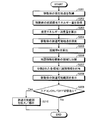
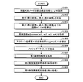
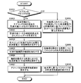
- FIG. 2 is a flowchart illustrating an example of an image processing procedure performed by the image processing apparatus.
- FIG. 3 is a schematic diagram showing the change of the reachable range by switching the air conditioner.
- FIG. 4 is a block diagram illustrating an example of a hardware configuration of the navigation device.
- FIG. 5A is an explanatory diagram schematically illustrating an example of reachable point search by the navigation device.
- FIG. 5B is an explanatory diagram schematically illustrating an example of reachable point search by the navigation device.
- FIG. 5C is an explanatory diagram schematically illustrating an example of reachable point search by the navigation device.
- FIG. 5A is an explanatory diagram schematically illustrating an example of reachable point search by the navigation device.
- FIG. 5B is an explanatory diagram schematically illustrating an example of reachable point search by the navigation device.
- FIG. 5C is an explanatory diagram
- FIG. 5-4 is an explanatory diagram schematically illustrating an example of reachable point search by the navigation device.
- FIG. 6A is an explanatory diagram of an example of reachable point search by the navigation device.
- FIG. 6B is an explanatory diagram of another example of the reachable point search by the navigation device.
- FIG. 7 is an explanatory diagram of an example showing the reachable point by the navigation device in longitude-latitude.
- FIG. 8 is an explanatory diagram of an example showing the reachable points by the navigation device as mesh data.
- FIG. 9 is an explanatory diagram illustrating an example of cloning processing by the navigation device.
- FIG. 10 is an explanatory diagram showing an example of the opening process by the navigation device.
- FIG. 11 is an explanatory diagram schematically illustrating an example of vehicle reachable range extraction by the navigation device.
- FIG. 12 is an explanatory diagram schematically illustrating an example of mesh data after the reachable range of the vehicle is extracted by the navigation device.
- FIG. 13 is an explanatory diagram schematically illustrating another example of vehicle reachable range extraction by the navigation device.
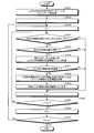
- FIG. 14 is a flowchart illustrating an example of an image processing procedure performed by the navigation device.
- FIG. 15 is a flowchart illustrating an example of a procedure of estimated power consumption calculation processing by the navigation device.
- FIG. 16A is a flowchart of an example of a procedure of reachable point search processing by the navigation device (part 1).
- FIG. 16-2 is a flowchart of an example of a procedure of reachable point search processing by the navigation device (part 2).
- FIG. 17 is a flowchart illustrating an example of a procedure of identification information addition processing by the navigation device.
- FIG. 18 is a flowchart illustrating an example of a procedure of first identification information change processing by the navigation device.
- FIG. 19A is a flowchart of an example of a reachable range contour extraction process performed by the navigation device (part 1).
- FIG. 19-2 is a flowchart of an example of a procedure of reachable range contour extraction processing by the navigation device (part 2).
- FIG. 20 is an explanatory diagram schematically illustrating an example of acceleration applied to a vehicle traveling on a road having a gradient.
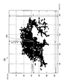
- FIG. 21 is an explanatory diagram illustrating an example of a display example after the reachable point search process by the navigation device.
- FIG. 22-1 is an explanatory diagram illustrating an example of a display example after the identification information providing process by the navigation device.
- FIG. 22-2 is an explanatory diagram showing an example of a display example after the first identification information changing process by the navigation device.
- FIG. 23 is an explanatory diagram illustrating an example of a display example after the cloning process (expansion) by the navigation device.
- FIG. 24 is an explanatory diagram illustrating an example of a display example after the cloning process (reduction) by the navigation device.
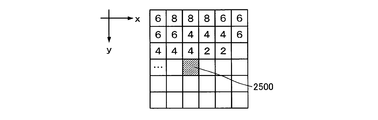
- FIG. 25A is a chart of power consumption stored as information on each node.
- FIG. 25A is a chart of power consumption stored as information on each node.
- FIG. 25-2 is a chart showing the required time stored as information of each node.
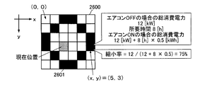
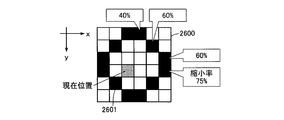
- FIG. 26 is a diagram for explaining a specific example of calculation of the reduction ratio.
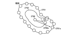
- FIG. 27A is a diagram for explaining image processing for reducing the reachable range (No. 1).
- FIG. 27B is a diagram for explaining image processing for reducing the reachable range (part 2).
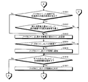
- FIG. 28 is a flowchart showing a procedure for reducing the reachable range.
- FIG. 29 is a diagram illustrating a specific example of calculation of the enlargement ratio.
- FIG. 30 is a flowchart illustrating a procedure for expanding the reachable range.
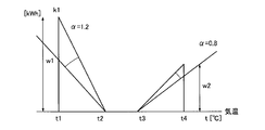
- FIG. 31 is a chart for explaining setting of the fuel consumption coefficient in consideration of temperature dependency.
- FIG. 32 is a chart for explaining the setting of the fuel consumption coefficient corresponding to the energy consumption due to the difference between air conditioning cooling and heating.
- FIG. 33 is a diagram for explaining the reachable range for each set temperature.
- FIG. 34 is a flowchart showing a procedure for changing the reachable range by changing the set temperature of the air conditioner.
- FIG. 35 is a block diagram of an example of a functional configuration of the image processing system according to the second embodiment.
- FIG. 36 is a block diagram of an example of a functional configuration of the image processing system according to the third embodiment.
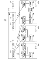
- FIG. 37 is an explanatory diagram of an example of a system configuration of the image processing apparatus according to the second embodiment.
- FIG. 1 is a block diagram of an example of a functional configuration of the image processing apparatus according to the first embodiment.
- the image processing apparatus 100 according to the first embodiment generates a reachable range of the moving object based on the reachable point of the moving object searched based on the remaining energy amount of the moving object and causes the display unit 110 to display the reachable range.
- the image processing apparatus 100 includes an acquisition unit 101, a calculation unit 102, a search unit 103, a division unit 104, a grant unit 105, a contour data calculation unit 106, an enlargement / reduction unit 107, and a display control unit 108.
- the energy is energy based on electricity in the case of an EV (Electric Vehicle) vehicle, for example, and in the case of HV (Hybrid Vehicle) vehicle, PHV (Plug-in Hybrid Vehicle) vehicle, etc.
- energy is energy based on electricity and the like, for example, hydrogen or a fossil fuel that becomes a hydrogen raw material (hereinafter, EV vehicle, HV vehicle, PHV vehicle, and fuel cell vehicle are simply “ EV car ").
- the energy is energy based on, for example, gasoline, light oil, gas, etc., for example, in the case of a gasoline vehicle, a diesel vehicle or the like (hereinafter simply referred to as “gasoline vehicle”).
- the residual energy is, for example, energy remaining in a fuel tank, a battery, a high-pressure tank, or the like of the moving body, and is energy that can be used for the subsequent traveling of the moving body.
- the acquisition unit 101 acquires information on the current location of the mobile object on which the image processing apparatus 100 is mounted and information on the initial stored energy amount that is the amount of energy held by the mobile object at the current location of the mobile object. Specifically, the acquisition unit 101 acquires information (position information) about the current location by calculating the current position of the device using, for example, GPS information received from a GPS satellite.
- the acquisition unit 101 determines the remaining energy amount of the moving body managed by an electronic control unit (ECU: Electronic Control Unit) via an in-vehicle communication network that operates according to a communication protocol such as CAN (Controller Area Network). , Get the initial amount of energy.
- ECU Electronic Control Unit
- CAN Controller Area Network
- the acquisition unit 101 may acquire information on the speed of the moving body, traffic jam information, and moving body information.
- the information regarding the speed of the moving body is the speed and acceleration of the moving body.
- the acquisition part 101 may acquire the information regarding a road from the map information memorize
- the information on the road is, for example, a running resistance generated in the moving body due to the road type, road gradient, road surface condition, and the like.
- the acquisition unit 101 acquires information on the operating state (change in energy consumption) of a device that is mounted on a moving body and consumes relatively large energy. For example, the energy consumed by the air conditioner is large, and the reachable range of the moving body varies greatly depending on whether the air conditioner is on or off.
- the energy consumed by the air conditioner is included in the first information (described later) when calculating the energy consumption.
- the acquisition unit 101 acquires the ON / OFF switching state of the air conditioner, the outside air temperature, the set temperature, etc. (air conditioner ON / OFF information) as information related to the change in energy consumed by the air conditioner.
- the outside air temperature can be detected using a temperature sensor, and the set temperature can be acquired from the air conditioner.
- the calculation unit 102 calculates an estimated energy consumption that is energy consumed when the moving body travels in a predetermined section.
- the predetermined section is, for example, a section (hereinafter referred to as “link”) connecting one predetermined point on the road (hereinafter referred to as “node”) and another node adjacent to the one node.
- the node may be, for example, an intersection or a stand, or a connection point between links separated by a predetermined distance.
- the nodes and links constitute map information stored in the storage unit.
- the map information includes, for example, vector data in which intersections (points), roads (lines and curves), regions (surfaces), colors for displaying these, and the like are digitized.
- the calculation unit 102 estimates an estimated energy consumption amount in a predetermined section based on a consumption energy estimation formula including the first information, the second information, and the third information. More specifically, the calculation unit 102 estimates an estimated energy consumption amount in a predetermined section based on information on the speed of the moving body and the moving body information.
- the moving body information is information that causes a change in the amount of energy consumed or recovered during traveling of the moving body, such as the weight of the moving body (including the number of passengers and the weight of the loaded luggage) and the weight of the rotating body.
- the calculation unit 102 may estimate the estimated energy consumption amount in the predetermined section based on the consumption energy estimation formula further including the fourth information.
- the energy consumption estimation formula is an estimation formula for estimating the energy consumption of the moving body in a predetermined section.
- the energy consumption estimation formula is a polynomial including first information, second information, and third information, which are different factors that increase or decrease the energy consumption. Further, when the road gradient is clear, fourth information is further added to the energy consumption estimation formula. Detailed description of the energy consumption estimation formula will be described later.
- the first information is information related to energy consumed by the equipment provided on the moving object. Moreover, it is the information regarding the energy consumed at the time of driving
- the first information is the amount of energy consumed due to factors not related to the traveling of the moving object. More specifically, the first information is the amount of energy consumed by equipment such as an air conditioner, a car audio, a headlight, a winker, and a brake pump provided in the moving body.
- equipment such as an air conditioner, a car audio, a headlight, a winker, and a brake pump provided in the moving body.
- the second information is information related to energy consumed and recovered during acceleration / deceleration of the moving body.
- the time of acceleration / deceleration of the moving body is a traveling state in which the speed of the moving body changes with time.
- the time of acceleration / deceleration of the moving body is a traveling state in which the speed of the moving body changes within a predetermined time.
- the predetermined time is a time interval at regular intervals, for example, per unit time.
- the recovered energy is, for example, electric power charged in a battery when the mobile body is traveling.
- the recovered energy is, for example, fuel that can be saved by reducing (fuel cut) the consumed fuel.
- the third information is information related to energy consumed by the resistance generated when the mobile object is traveling.
- the traveling time of the moving body is a traveling state where the speed of the moving body is constant, accelerated or decelerated within a predetermined time.
- the resistance generated when the mobile body travels is a factor that changes the travel state of the mobile body when the mobile body travels. Specifically, the resistance generated when the mobile body travels is various resistances generated in the mobile body due to weather conditions, road conditions, vehicle conditions, and the like.
- the resistance generated in the moving body due to the weather condition is, for example, air resistance due to weather changes such as rain and wind.
- the resistance generated in the moving body according to the road condition is road resistance due to road gradient, pavement state of road surface, water on the road surface, and the like.
- the resistance generated in the moving body depending on the vehicle condition is a load resistance applied to the moving body due to tire air pressure, number of passengers, loaded weight, and the like.
- the third information is energy consumption when the moving body is driven at a constant speed, acceleration or deceleration while receiving air resistance, road resistance, and load resistance. More specifically, the third information is consumed when the moving body travels at a constant speed, acceleration or deceleration, for example, air resistance generated in the moving body due to the head wind or road surface resistance received from a road that is not paved. Energy consumption.
- the fourth information is information related to energy consumed and recovered by a change in altitude where the moving object is located.
- the change in altitude at which the moving body is located is a state in which the altitude at which the moving body is located changes over time.
- the change in altitude at which the moving body is located is a traveling state in which the altitude changes when the moving body travels on a sloped road within a predetermined time.
- the fourth information is additional information that can be obtained when the road gradient in the predetermined section is clear, thereby improving the estimation accuracy of energy consumption.
- the calculation unit 102 calculates the energy consumption amount when the air conditioner is turned on with respect to the information on the change in the energy consumed constantly (air conditioner ON / OFF information) acquired by the acquisition unit 101. Then, an enlargement / reduction ratio (reduction ratio or enlargement ratio) indicating the degree (ratio) of change in the amount of energy when the air conditioner is ON and when the air conditioner is OFF is obtained. For example, if the air conditioner is OFF during the search, the energy consumption when the air conditioner is assumed to be on is estimated based on the energy consumption in the state where there is no power consumption by the air conditioner, and the expansion / contraction rate that is the ratio of these is calculated. Ask. In this case, it is assumed that the air conditioner consumes constant power when it is turned on.
- the search unit 103 is based on the map information stored in the storage unit, the current location and initial stored energy amount of the mobile object acquired by the acquisition unit 101, and the estimated energy consumption calculated by the calculation unit 102. Search for a plurality of reachable points that can be reached from the current point.
- the search unit 103 starts from the current location of the mobile object, and in a predetermined section connecting predetermined points on the route from the mobile object. A predetermined point and a predetermined section are searched so that the total of the estimated energy consumption is minimized. Then, the search unit 103 moves the mobile unit to a predetermined point where the total estimated energy consumption amount is within the range of the initial stored energy amount of the mobile unit in all routes that can move from the current point of the mobile unit.
- the search unit 103 starts from the current location of the mobile object as a starting point, all links that can be moved from the current location of the mobile object, nodes that connect to these links, and all that can be moved from these nodes. , And all the nodes and links that can be reached by the moving object.
- the search unit 103 each time the search unit 103 searches for a new link, the search unit 103 accumulates the estimated energy consumption of the route to which the one link is connected, and the accumulated energy consumption is minimized. Search for a node connected to the link and a plurality of links connected to this node.
- the search unit 103 estimates the estimated energy consumption from the current location of the mobile body to the node among the plurality of links connected to the node.
- the estimated energy consumption of the relevant node is calculated using the estimated energy consumption of the link with a small amount of accumulation.
- the search unit 103 sets all the nodes whose accumulated energy consumption amount is within the range of the initial stored energy amount of the mobile object, respectively. Search as a reachable point.
- it is possible to calculate the correct total of the estimated energy consumption of the node.
- the search unit 103 may search for a reachable point by excluding a predetermined section in which movement of the mobile object is prohibited from candidates for searching for a reachable point of the mobile object.
- the predetermined section in which the movement of the moving body is prohibited is, for example, a link that is one-way reverse running, or a link that is a passage-prohibited section due to time restrictions or seasonal restrictions.
- the time restriction is, for example, that traffic is prohibited in a certain time zone by being set as a school road or an event.
- the seasonal restriction is, for example, that traffic is prohibited due to heavy rain or heavy snow.
- the search unit 103 selects another predetermined section as a mobile object.
- the reachable point may be searched for by removing it from the candidates for searching for the reachable point.
- the importance of the predetermined section is, for example, a road type.
- the road type is a type of road that can be distinguished by differences in road conditions such as legal speed, road gradient, road width, and presence / absence of signals.
- the road type is a narrow street that passes through a general national road, a highway, a general road, an urban area, or the like.
- a narrow street is, for example, a road defined in the Building Standard Law with a width of less than 4 meters in an urban area.
- the search unit 103 moves all the areas constituting one bridge or one tunnel of the map information divided by the dividing unit 104. It is preferable to search for a reachable point of the moving body so as to be included in the reachable range of the body. Specifically, for example, when the entrance of one bridge or one tunnel is a reachable point of the mobile object, the search unit 103 is located on one bridge or one tunnel from the entrance of the one bridge or one tunnel toward the exit. You may search the said reachable point so that several reachable points may be searched.
- the entrance of one bridge or one tunnel is the starting point of one bridge or one tunnel on the side close to the current position of the moving object.
- the search unit 103 When the search unit 103 performs a search, the air conditioner is in the ON or OFF state, and the search is performed in either state. If you search when the air conditioner is ON, the reachable point will be shorter due to the amount of energy consumed by the air conditioner. On the other hand, if you search when the air conditioner is OFF, there will be no energy consumed by the air conditioner. The point becomes longer.
- the search unit 103 does not search again even when the air conditioner is switched ON / OFF. That is, based on the reachable point obtained by searching once, the movable range of the moving body (contour data) to be described later is expanded by the expansion / contraction unit 107 corresponding to the ON / OFF of the air conditioner. Alternatively, reduction image processing is performed. Although details will be described later, when the air conditioner is turned on after displaying the movable range by the search when the air conditioner is OFF, the movable range is reduced, and after displaying the movable range by the search when the air conditioner is ON, the air conditioner When it is turned off, the movable range is expanded.
- the dividing unit 104 divides the map information into a plurality of areas. Specifically, the dividing unit 104 divides the map information into a plurality of rectangles based on a reachable point farthest from the current point of the mobile object among a plurality of reachable points of the mobile object searched by the search unit 103. It is divided into shape areas and converted into mesh data of m ⁇ m dots, for example.
- the m ⁇ m dot mesh data is handled as raster data (image data) to which identification information is added by the adding unit 105 described later. Note that each m of m ⁇ m dots may be the same numerical value or a different numerical value.
- the dividing unit 104 extracts the maximum longitude, the minimum longitude, the maximum latitude, and the minimum latitude, and calculates the distance from the current position of the moving object. Then, the dividing unit 104 divides the map information into a plurality of areas, for example, by dividing the size of one area when the reachable point farthest from the current position of the moving object and the current position of the moving object are equally divided into n.
- the map information is divided into mesh data of m ⁇ m dots.
- the assigning unit 105 assigns identification information for identifying whether or not the mobile body can reach each of the plurality of areas divided by the dividing unit 104 based on the plurality of reachable points searched by the search unit 103. To do. Specifically, when the reachable point of the moving object is included in one area divided by the dividing unit 104, the granting unit 105 can reach the one area to identify that the moving object is reachable. The identification information is assigned. After that, when the reachable point of the moving object is not included in the one area divided by the dividing unit 104, the assigning unit 105 identifies that the moving object cannot reach the one area. The identification information is assigned.
- the assigning unit 105 assigns reachable identification information “1” or unreachable identification information “0” to each area of the mesh data divided into m ⁇ m. It is converted into mesh data of two-dimensional matrix data in rows and m columns.
- the dividing unit 104 and the assigning unit 105 divide the map information in this way, convert it into mesh data of 2D matrix data of m rows and m columns, and handle it as binarized raster data.
- the grant unit 105 includes a first change unit and a second change unit that perform identification information change processing on a plurality of areas divided by the division unit 104. Specifically, the adding unit 105 treats mesh data obtained by dividing the map information by the first changing unit and the second changing unit as binarized raster data, and performs a cloning process (a reduction process after the expansion process). Process). Further, the granting unit 105 may perform an opening process (a process of performing an expansion process after the reduction process) by the first changing unit and the second changing unit.
- the first changing unit can reach the identification information of the one area when the identification information that can reach another area adjacent to the one area to which the identification information is given is given. Change to identification information (expansion process). More specifically, the first changing unit is any one of the other regions adjacent to the left, bottom, bottom, bottom right, right, top right, top, top left, and left of one rectangular region. If “1”, which is identification information that can reach the area, is assigned, the identification information of the one area is changed to “1”.
- the one region Is changed to unreachable identification information (reduction processing).
- the second changing unit is any one of the other regions adjacent to each other in the eight directions of lower left, lower, lower right, right, upper right, upper, upper left, and left of one rectangular region. If “0”, which is identification information that cannot reach the area, is assigned, the identification information of the one area is changed to “0”.
- the expansion process by the first changing unit and the reduction process by the second changing unit are performed the same number of times.
- the granting unit 105 can reach the area including the reachable point, which is the point where the moving body can reach from the current point, among the plurality of areas divided by the dividing unit 104. Reachable identification information for identifying this is given to make the movable body reachable. Thereafter, the assigning unit 105 assigns reachable identification information to a region adjacent to the region to which reachable identification information is assigned, and the identification information of each region so that no missing point is generated in the reachable range of the moving object. To change.
- the reachable identification information for identifying that the reachable unit 105 is reachable is assigned to the divided map information corresponding to the entrance and exit of one bridge or one tunnel of the map information
- Reachable identification means is assigned to the divided map information corresponding to all areas constituting one bridge or one tunnel.
- the granting unit 105 corresponds to the entrance of one bridge or one tunnel, for example, when the reachable identification information is given to each area corresponding to the entrance and exit of one bridge or one tunnel, respectively. Identification information that can reach all areas where the moving body can move from the area to the area corresponding to the exit is given.
- the assigning unit 105 has identification information “1” that is reachable to each region corresponding to the entrance and exit of one bridge or one tunnel before the expansion processing by the first changing unit, for example. All areas located on the section connecting the area corresponding to the entrance and exit of one bridge or tunnel when there is a defect point on one bridge or tunnel when given Is changed to “1”.
- the section connecting the area corresponding to the entrance of one bridge or tunnel and the area corresponding to the exit may be a section corresponding to a road including a plurality of curves, or a single straight road. It may be a section.
- the acquisition unit 101, the calculation unit 102, the search unit 103, the division unit 104, the grant unit 105, and the contour data calculation unit 106 constitute a reachable range calculation unit 109.
- the reachable range calculation unit 109 includes information on the current position of the moving body, information on the amount of energy held by the moving body, information on changes in the operating state of the equipment included in the moving body, A reachable range including a plurality of reachable areas of the moving body is calculated based on an estimated energy consumption amount indicating an energy amount consumed when traveling.
- the contour data calculation unit 106 calculates the contour data of the contour of the reachable range given by the grant unit 105.
- the outer contour of the reachable range is calculated by connecting the outermost contour to which the reachable identification information “1” is assigned.
- the contour of the reachable range of the mobile object can be calculated using, for example, a Freeman chain code.
- the contour data calculation unit 106 outputs the chain code value (sequence) for each identification information for the reachable range.
- the enlargement / reduction unit 107 enlarges or reduces the area of the reachable range of the moving object indicated by the outline data calculated by the outline data calculation unit 106, that is, the identification information of the area to which the identification information is given.
- the reachable range is enlarged or reduced when the air conditioner is switched ON / OFF.
- the enlargement / reduction unit 107 reduces the reachable range.
- the expansion / contraction unit 107 expands the reachable range.
- the ratio at which the reachable range is enlarged or reduced is determined based on the enlargement / reduction ratio output by the calculation unit 102.
- the display control unit 108 causes the display unit 110 to display the reachable range of the mobile object together with the map information based on the identification information of the area to which the identification information is given by the granting unit 105. Specifically, the display control unit 108 converts mesh data, which is a plurality of image data to which identification information has been added by the adding unit 105, into vector data, and displays it on the display unit 110 together with the map information stored in the storage unit.
- the display control unit 108 extracts the contour of the reachable range of the moving object calculated by the contour data calculation unit 106 and causes the display unit 110 to display the contour that has been enlarged or reduced by the enlargement / reduction unit 107. .
- FIG. 2 is a flowchart illustrating an example of an image processing procedure performed by the image processing apparatus.
- the image processing apparatus 100 first uses the acquisition unit 101 to obtain information on the current location of the moving object and information on the initial amount of energy held by the moving object at the current location of the moving object. Are acquired (steps S201 and S202). At this time, the image processing apparatus 100 may also acquire moving body information.
- the calculation unit 102 calculates an estimated energy consumption that is energy consumed when the moving body travels in a predetermined section (step S203). At this time, the image processing apparatus 100 calculates estimated energy consumption amounts in a plurality of predetermined sections connecting predetermined points on the path of the moving body.
- the image processing apparatus 100 uses the search unit 103 based on the map information stored in the storage unit and the initial stored energy amount and the estimated energy consumption amount acquired in steps S202 and S203. A reachable point is searched (step S204).
- the expansion / contraction rate K with respect to the reachable range corresponding to the difference in energy consumption due to ON / OFF of the air conditioner is calculated (step S205).
- the image processing apparatus 100 uses the dividing unit 104 to divide the map information made up of vector data into a plurality of regions and convert it into mesh data made up of raster data (step S206).
- the image processing apparatus 100 assigns reachable identification information to each of the plurality of regions divided in step S206 based on the plurality of reachable points searched in step S204 (step S207).
- the image processing apparatus 100 causes the display control unit 108 to display the reachable range of the moving object on the display unit 110 based on the identification information of the plurality of areas to which the identification information is assigned in step S207 (step S208).
- step S209 After the reachable range of the moving object is displayed by the above one-time search, it is determined whether the air conditioner has been switched ON / OFF (step S209). If switching of the air conditioner ON / OFF is not detected by the acquisition unit 101 (step S209: No), the above processing is terminated, but when the air conditioner is switched after one search and display of the reachable range (step S209) (S209: Yes), the reachable range of the moving body being displayed is enlarged or reduced in accordance with ON / OFF of the air conditioner (step S210), and the above processing is terminated.
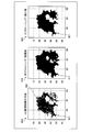
- Fig. 3 is a schematic diagram showing the change of the reachable range by switching the air conditioner.
- (A) when the air conditioner is switched on after the reachable range 301 is displayed in the state where the air conditioner is OFF during the search by the search unit 103, the reachable range 301 is changed to the reduced range 302.
- (B) when the air conditioner is switched off after the reachable range 303 is displayed with the air conditioner turned on during the search by the search unit 103, the reachable range 303 is changed to the enlarged range 304. To do. This enlargement / reduction change is performed, for example, based on the current location of the moving object included in the reachable range.
- the expansion / contraction rate is the ratio of energy consumption by the air conditioner when the air conditioner is ON and OFF.
- the reachable range 301 based on the accumulated energy consumption (total power consumption) when searching when the air conditioner is OFF is reduced to the reduced range 302 when the air conditioner is ON.
- Total power consumption (air conditioner ON) total power consumption (air conditioner OFF) + required time x fuel efficiency factor k1 It becomes.
- Reduction rate at this time represented by total power consumption (air conditioner OFF) / total power consumption (air conditioner ON).
- the reachable range 303 based on the accumulated energy consumption (total power consumption) when the search is performed when the air conditioner is ON is changed to the expanded range 304 when the air conditioner is OFF.
- Total power consumption (air conditioner OFF) total power consumption (air conditioner ON)-required time x fuel efficiency coefficient k1 It becomes.
- the expansion ratio at this time is expressed as: total power consumption (air conditioner ON) / total power consumption (air conditioner OFF).
- the image processing apparatus 100 divides the map information into a plurality of areas, searches whether each moving area can be reached, and moves each moving area to each area.
- the reachable identification information for identifying that is reachable is given.
- the image processing apparatus 100 generates a reachable range of the moving object based on the region to which reachable identification information is assigned. For this reason, the image processing apparatus 100 can generate the reachable range of the moving object in a state excluding areas where the moving object cannot travel, such as the sea, lakes, and mountain ranges. Therefore, the image processing apparatus 100 can accurately display the reachable range of the moving object.
- the image processing apparatus 100 converts a plurality of areas obtained by dividing the map information into image data, assigns each reachable identification information to the plurality of areas, and then performs an expansion process of cloning. For this reason, the image processing apparatus 100 can remove missing points within the reachable range of the moving object.
- the image processing apparatus 100 converts a plurality of areas obtained by dividing the map information into image data, assigns each reachable identification information to the plurality of areas, and then performs an opening reduction process. For this reason, the image processing apparatus 100 can remove isolated points in the reachable range of the moving object.
- the image processing apparatus 100 can remove missing points and isolated points in the reachable range of the moving body, and therefore, the travelable range of the moving body can be displayed on a two-dimensional smooth surface in an easy-to-read manner. it can.
- the image processing apparatus 100 also extracts the outline of mesh data generated by dividing the map information into a plurality of regions. For this reason, the image processing apparatus 100 can display the outline of the reachable range of the moving object smoothly.
- the image processing apparatus 100 narrows down the road for searching for the reachable point of the moving object, and searches for the reachable point of the moving object. For this reason, the image processing apparatus 100 can reduce the processing amount at the time of searching the reachable point of a moving body. Even if the number of reachable reachable points is reduced by narrowing down the road to search for the reachable points of the mobile object, the expansion process of cloning is performed as described above, so that the reachable range of the mobile object is within the reachable range. The resulting defect point can be removed. Therefore, the image processing apparatus 100 can reduce the processing amount for generating the reachable range of the moving object. In addition, the image processing apparatus 100 can display the travelable range of the moving object in a two-dimensional smooth manner so that it can be easily seen.
- the reachable range to be displayed is expanded or reduced based on the operating state of a device that is installed in a moving body such as an air conditioner and consumes relatively large energy.
- a device that is installed in a moving body such as an air conditioner and consumes relatively large energy.
- Example 1 of the present invention will be described.
- the navigation apparatus 400 mounted on a vehicle as the image processing apparatus 100 will be described using the navigation apparatus 400 mounted on a vehicle as the image processing apparatus 100.
- FIG. 4 is a block diagram illustrating an example of a hardware configuration of the navigation device.
- a navigation device 400 includes a CPU 401, ROM 402, RAM 403, magnetic disk drive 404, magnetic disk 405, optical disk drive 406, optical disk 407, audio I / F (interface) 408, microphone 409, speaker 410, input device 411, A video I / F 412, a display 413, a camera 414, a communication I / F 415, a GPS unit 416, and various sensors 417 are provided.
- Each component 401 to 417 is connected by a bus 420.
- the CPU 401 is responsible for overall control of the navigation device 400.
- the ROM 402 stores programs such as a boot program, an estimated energy consumption calculation program, a reachable point search program, an identification information addition program, and a map data display program.
- the RAM 403 is used as a work area for the CPU 401. That is, the CPU 401 controls the entire navigation device 400 by executing various programs recorded in the ROM 402 while using the RAM 403 as a work area.
- an estimated energy consumption in a link connecting one node and an adjacent node is calculated based on an energy consumption estimation formula for calculating an estimated energy consumption of the vehicle.
- the reachable point search program a plurality of points (nodes) that can be reached with the remaining energy amount at the current point of the vehicle are searched based on the estimated energy consumption calculated in the estimation program.
- identification information providing program identification information for identifying that the vehicle is reachable is provided to a plurality of areas obtained by dividing the map information based on the plurality of reachable points searched in the search program.
- the reachable range of the vehicle is displayed on the display 413 based on the plurality of areas to which the identification information is given by the identification information giving program.
- the magnetic disk drive 404 controls the reading / writing of the data with respect to the magnetic disk 405 according to control of CPU401.
- the magnetic disk 405 records data written under the control of the magnetic disk drive 404.
- an HD hard disk
- FD flexible disk
- the optical disk drive 406 controls reading / writing of data with respect to the optical disk 407 according to the control of the CPU 401.
- the optical disc 407 is a detachable recording medium from which data is read according to the control of the optical disc drive 406.
- a writable recording medium can be used as the optical disc 407.
- an MO, a memory card, or the like can be used as a removable recording medium.
- Examples of information recorded on the magnetic disk 405 and the optical disk 407 include map data, vehicle information, road information, travel history, and the like. Map data is used when searching for a reachable point of a vehicle in a car navigation system or when displaying a reachable range of a vehicle. Background data representing features (features) such as buildings, rivers, the ground surface, This is vector data including road shape data that expresses the shape of the road by links and nodes.
- the voice I / F 408 is connected to a microphone 409 for voice input and a speaker 410 for voice output.
- the sound received by the microphone 409 is A / D converted in the sound I / F 408.
- the microphones 409 are installed, for example, in a dashboard portion of the vehicle, and the number thereof may be singular or plural. From the speaker 410, a sound obtained by D / A converting a predetermined sound signal in the sound I / F 408 is output.
- the input device 411 may be a remote controller having a plurality of keys for inputting characters, numerical values, various instructions, a keyboard, a touch panel, and the like.
- the input device 411 may be realized by any one form of a remote control, a keyboard, and a touch panel, but may be realized by a plurality of forms.
- the video I / F 412 is connected to the display 413.
- the video I / F 412 is output from, for example, a graphic controller that controls the entire display 413, a buffer memory such as a VRAM (Video RAM) that temporarily records image information that can be displayed immediately, and a graphic controller.
- a control IC for controlling the display 413 based on the image data to be processed.
- the display 413 displays icons, cursors, menus, windows, or various data such as characters and images.
- a TFT liquid crystal display, an organic EL display, or the like can be used as the display 413.
- the camera 414 captures images inside or outside the vehicle.
- the image may be either a still image or a moving image.
- the outside of the vehicle is photographed by the camera 414, and the photographed image is analyzed by the CPU 401, or a recording medium such as the magnetic disk 405 or the optical disk 407 via the image I / F 412. Or output to
- the communication I / F 415 is connected to the network via wireless and functions as an interface between the navigation device 400 and the CPU 401.
- Communication networks that function as networks include in-vehicle communication networks such as CAN and LIN (Local Interconnect Network), public line networks and mobile phone networks, DSRC (Dedicated Short Range Communication), LAN, and WAN.
- the communication I / F 415 is, for example, a public line connection module, an ETC (non-stop automatic fee payment system) unit, an FM tuner, a VICS (Vehicle Information and Communication System) (registered trademark) / beacon receiver, or the like.
- the GPS unit 416 receives radio waves from GPS satellites and outputs information indicating the current position of the vehicle.
- the output information of the GPS unit 416 is used when the CPU 401 calculates the current position of the vehicle together with output values of various sensors 417 described later.
- the information indicating the current position is information for specifying one point on the map data, such as latitude / longitude and altitude.
- Various sensors 417 output information for determining the position and behavior of the vehicle, such as a vehicle speed sensor, an acceleration sensor, an angular velocity sensor, and a tilt sensor.
- the output values of the various sensors 417 are used by the CPU 401 to calculate the current position of the vehicle and the amount of change in speed and direction.
- the CPU 401 executes a predetermined program using programs and data recorded in the ROM 402, RAM 403, magnetic disk 405, optical disk 407, etc. in 400, and realizes its function by controlling each part in the navigation device 400.
- the navigation apparatus 400 of the present embodiment calculates the estimated energy consumption of the vehicle on which the own apparatus is mounted.
- the navigation device 400 may be any one or more of energy consumption estimation formulas including first information, second information, and third information based on, for example, speed, acceleration, and vehicle gradient. Is used to calculate the estimated energy consumption of the vehicle in a predetermined section.
- the predetermined section is a link connecting one node (for example, an intersection) on the road and another node adjacent to the one node.
- the navigation device 400 determines whether the vehicle is linked based on traffic jam information provided by the probe, traffic jam prediction data acquired via a server, link length or road type stored in the storage device, and the like. The travel time required to finish driving is calculated. Then, navigation device 400 calculates an estimated energy consumption amount per unit time using any one of the following energy consumption estimation formulas (1) to (4), and the vehicle travels the link for the travel time. Calculate the estimated energy consumption when finishing.
- the energy consumption estimation formula shown in the above equation (1) is a theoretical formula for estimating the energy consumption per unit time during acceleration and traveling.
- ⁇ is the net thermal efficiency and ⁇ is the total transmission efficiency.
- is negative is expressed by the above equation (2).
- the energy consumption estimation formula shown in the above equation (2) is a theoretical formula for estimating the energy consumption per unit time during deceleration.
- the energy consumption estimation formula per unit time during acceleration / deceleration and travel is expressed by the product of travel resistance, travel distance, net motor efficiency, and transmission efficiency.
- the first term on the right side is the energy consumption (first information) consumed by the equipment provided in the moving body.
- the second term on the right side is the energy consumption (fourth information) due to the gradient component and the energy consumption (third information) due to the rolling resistance component.
- the third term on the right side is energy consumption (third information) due to the air resistance component.
- the fourth term on the right side of the equation (1) is the energy consumption (second information) by the acceleration component.
- the fourth term on the right side of equation (2) is the energy consumption (second information) due to the deceleration component.
- is positive, that is, the empirical formula for calculating the estimated energy consumption per unit time during acceleration and traveling is (3) It is expressed by a formula.
- is negative, that is, the empirical formula for calculating the estimated energy consumption per unit time during deceleration is the following formula (4): It is represented by
- the coefficients a1 and a2 are constants set according to the vehicle situation.
- the coefficient k1 is a variable based on the amount of energy consumed during traveling and stopping including acceleration / deceleration.
- the coefficients k2 and k3 are variables based on the energy consumption during traveling including acceleration / deceleration. Further, the speed V and the acceleration A are set, and other variables are the same as the above formulas (1) and (2).
- the first term on the right side corresponds to the first term on the right side of the above equations (1) and (2).
- the coefficient k1 corresponds to the fuel efficiency coefficient k1 described above.
- the second term on the right side is the energy of the gradient resistance component in the second term on the right side and the acceleration in the fourth term on the right side in the formulas (1) and (2). It corresponds to the energy of the resistance component.
- the third term on the right side corresponds to the energy of the rolling resistance component in the second term on the right side and the energy of the air resistance component in the third term on the right side in the above equations (1) and (2).
- ⁇ in the second term on the right side of the equation (4) is the amount of potential energy and kinetic energy recovered (hereinafter referred to as “recovery rate”).
- the navigation device 400 calculates the travel time required for the vehicle to travel the link as described above, and calculates the average speed and average acceleration when the vehicle travels the link. Then, the navigation device 400 uses the average speed and average acceleration of the vehicle at the link, and the vehicle travels on the link in the travel time based on the consumption energy estimation equation shown in the following equation (5) or (6). You may calculate the estimated energy consumption at the time of finishing.
- the consumption energy estimation formula shown in the above formula (5) is a theoretical formula for calculating the estimated energy consumption at the link when the altitude difference ⁇ h of the link on which the vehicle travels is positive.
- the case where the altitude difference ⁇ h is positive is a case where the vehicle is traveling uphill.
- the energy consumption estimation formula shown in the above equation (6) is a theoretical formula for calculating an estimated energy consumption amount in the link when the altitude difference ⁇ h of the link on which the vehicle travels is negative.
- the case where the altitude difference ⁇ h is negative is a case where the vehicle is traveling downhill.
- the first term on the right side is the energy consumption (first information) consumed by the equipment provided in the moving body.
- the second term on the right side is the energy consumption (second information) by the acceleration resistance.
- the third term on the right side is energy consumption consumed as potential energy (fourth information).
- the fourth term on the right side is the energy consumption (third information) due to the air resistance and rolling resistance (running resistance) received per unit area.
- the recovery rate ⁇ used in the above equations (1) to (6) will be described.
- the energy consumption amount P acc of the acceleration component is calculated from the total energy consumption amount (left side) of the link from the energy at idling. This is obtained by subtracting the amount of consumption (first term on the right side) and the amount of energy consumed by the running resistance (fourth term on the right side), and is expressed by the following equation (7).
- the recovery rate ⁇ is about 0.7 to 0.9 for EV vehicles, about 0.6 to 0.8 for HV vehicles, and about 0.2 to 0.3 for gasoline vehicles.
- the recovery rate of the gasoline vehicle is a ratio of energy required for acceleration and energy recovered for deceleration.
- the navigation device 400 searches for a plurality of nodes that can be reached from the current location of the vehicle on which the device is mounted as reachable locations of the vehicle. Specifically, the navigation apparatus 400 calculates the estimated energy consumption in the link using any one or more of the energy consumption estimation formulas shown in the above formulas (1) to (6). Then, the navigation apparatus 400 searches for a reachable node of the vehicle so that the cumulative total of estimated energy consumption in the link is minimized, and sets it as a reachable point. Below, an example of the reachable point search by the navigation apparatus 400 is demonstrated.
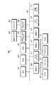
- FIGS. 5-1 to 5-4 are explanatory diagrams schematically showing an example of reachable point search by the navigation device 400.
- FIG. In FIGS. 5-1 to 5-4 nodes (for example, intersections) of map data are indicated by circles, and links (predetermined sections on the road) connecting adjacent nodes are indicated by line segments (FIGS. 6-1, 6). Similarly, nodes and links are shown for -2.
- the navigation device 400 first searches for the link L1_1 closest to the current location 500 of the vehicle. Then, navigation device 400 searches for node N1_1 connected to link L1_1 and adds it to a node candidate for searching for a reachable point (hereinafter simply referred to as “node candidate”).
- the navigation apparatus 400 calculates an estimated energy consumption amount in the link L1_1 that connects the current location 500 of the vehicle and the node N1_1 that is a node candidate using the energy consumption estimation formula. Then, the navigation device 500 writes the estimated energy consumption 3wh in the link L1_1 to the storage device (magnetic disk 405 or optical disk 407) in association with the node N1_1, for example.
- the storage device magnetic disk 405 or optical disk 407
- the navigation apparatus 400 searches for all links L2_1, L2_2, and L2_3 connected to the node N1_1 and searches for reachable points (hereinafter simply referred to as “links”). "Candidate”).
- the navigation apparatus 400 calculates the estimated energy consumption amount in the link L2_1 using the consumption energy estimation formula.
- the navigation device 400 writes the accumulated energy amount 7wh obtained by accumulating the estimated energy consumption amount 4wh in the link L2_1 and the estimated energy consumption amount 3wh in the link L1_1 to the storage device in association with the node N2_1 connected to the link L2_1 (hereinafter referred to as the storage device). , “Set cumulative energy amount to node”).
- the navigation apparatus 400 calculates the estimated energy consumption in the links L2_2 and L2_3, respectively, using the energy consumption estimation formula as in the case of the link L2_1. Then, the navigation apparatus 400 sets the accumulated energy amount 8wh obtained by accumulating the estimated energy consumption amount 5wh in the link L2_2 and the estimated energy consumption amount 3wh in the link L1_1 in the node N2_2 connected to the link L2_2.
- the navigation device 400 sets the accumulated energy amount 6wh obtained by accumulating the estimated energy consumption amount 3wh in the link L2_3 and the estimated energy consumption amount 3wh in the link L1_1 to the node N2_3 connected to the link L2_3. At this time, if the node for which the cumulative energy amount is set is not a node candidate, navigation device 400 adds the node to the node candidate.
- the navigation apparatus 400 includes all links L3_1, L3_2_1 connected to the node N2_1, all links L3_2_2, L3_3, L3_4 connected to the node N2_2, and links connected to the node N2_3.
- L3_5 is searched for as a link candidate.
- the navigation apparatus 400 calculates the estimated energy consumption in the links L3_1 to L3_5 using the consumption energy estimation formula.
- the navigation apparatus 400 accumulates the estimated energy consumption 4wh in the link L3_1 to the accumulated energy amount 7wh set in the node N2_1, and sets the accumulated energy amount 11wh in the node N3_1 connected to the link L3_1.
- the navigation apparatus 400 sets the cumulative energy amounts 13wh, 12wh, and 10wh in the nodes N3_3 to N3_5 connected to the links L3_3 to L3_5, respectively, in the links L3_3 to L3_5 as in the case of the link L3_1.
- the navigation apparatus 400 accumulates the estimated energy consumption 5wh in the link L3_3 to the accumulated energy amount 8wh set in the node N2_2, and sets the accumulated energy amount 13wh in the node N3_3.
- the navigation device 400 accumulates the estimated energy consumption 4wh in the link L_3_4 to the accumulated energy amount 8wh set in the node N2_2, and sets the accumulated energy amount 12wh in the node N3_4.
- the navigation device 400 accumulates the estimated energy consumption 4wh in the link L3_5 to the accumulated energy amount 6wh set in the node N2_3, and sets the accumulated energy amount 10wh in the node N3_5.
- the navigation device 400 includes the cumulative energy amount in a plurality of routes from the vehicle current point 500 to the one node N3_2.
- the minimum accumulated energy amount 10wh is set in the one node N3_2.
- the navigation device 400 When there are a plurality of nodes in the same hierarchy from the current location 500 of the vehicle, such as the above-described nodes N2_1 to N2_3, the navigation device 400, for example, from a link connected to a node having the low cumulative energy amount among the nodes at the same level.
- the estimated energy consumption and the cumulative energy amount are calculated in order.
- navigation device 400 calculates an estimated energy consumption amount for each link connected to each node in the order of node N2_3, node N2_1, and node N2_2, and accumulates the accumulated energy amount for each node.
- the navigation device 400 continues to accumulate the accumulated energy amount as described above from the nodes N3_1 to N3_5 to the deeper level nodes. Then, the navigation device 400 extracts all nodes set with a cumulative energy amount equal to or less than a preset designated energy amount as reachable points of the vehicle, and obtains longitude / latitude information of the nodes extracted as reachable points. Write to the storage device in association with each node.
- the navigation device 400 when the designated energy amount is 10wh, the navigation device 400, as shown by a hatched circle in FIG. 5-4, is a node N1_1 to which a cumulative energy amount of 10wh or less is set. N2_1, N2_2, N2_3, N3_2, and N3_5 are extracted as reachable points of the vehicle.
- the designated energy amount set in advance is, for example, the remaining energy amount (initial stored energy amount) at the current point 500 of the vehicle.
- the map data 540 composed of the current location 500 of the vehicle and a plurality of nodes and links shown in FIG. 5-4 is an example for explaining the reachable location search, and the navigation device 400 is actually shown in FIG. As shown in FIG. 1, more nodes and links are searched in a wider range than the map data 540 shown in FIG. 5-4.
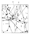
- FIG. 6A is an explanatory diagram showing an example of reachable point search by the navigation device 400.
- search the total energy amount in all nodes on each road in detail. can do.
- the estimated energy consumption of approximately 2 million links in Japan is calculated and accumulated, and the information processing amount of the navigation device 400 becomes enormous.
- the navigation apparatus 400 may narrow down the road which searches for the reachable point of a mobile body based on the importance of a link etc., for example.
- FIG. 6B is an explanatory diagram showing another example of the reachable point search by the navigation device 400.
- the navigation device 400 calculates the cumulative energy amount on all roads (excluding narrow streets) around the current point 500 of the vehicle, and only high-importance roads are within a certain distance away. To calculate the total energy.
- the number of nodes and the number of links searched by the navigation device 400 can be reduced, and the information processing amount of the navigation device 400 can be reduced. Therefore, the processing speed of the navigation device 400 can be improved.
- the navigation device 400 divides the map data stored in the storage device based on the reachable point searched as described above. Specifically, the navigation device 400 converts map data composed of vector data into, for example, 64 ⁇ 64 dot mesh data (X, Y), and converts the map data into raster data (image data).
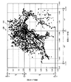
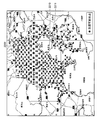
- FIG. 7 is an explanatory diagram of an example in which a reachable point by the navigation device 400 is indicated by longitude-latitude.
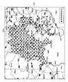
- FIG. 8 is an explanatory diagram of an example in which a reachable point by the navigation device 400 is indicated by mesh data.
- FIG. 7 illustrates, for example, longitude and latitude information (x, y) of reachable points searched for as shown in FIGS. 6-1 and 6-2 in absolute coordinates.
- FIG. 8 illustrates screen data of 64 ⁇ 64 dot mesh data (X, Y) to which identification information is given based on reachable points.
- the navigation apparatus 400 first generates longitude / latitude information (x, y) having a point group 700 in absolute coordinates based on the longitude x and latitude y of each of a plurality of reachable points. .
- the origin (0, 0) of the longitude / latitude information (x, y) is at the lower left of FIG.
- the navigation apparatus 400 calculates the distances w1 and w2 from the longitude ofx of the current point 500 of the vehicle to the maximum longitude x_max and the minimum longitude x_min of the reachable point farthest in the longitude x direction.
- the navigation device 400 calculates the distances w3 and w4 from the latitude of the current location 500 of the vehicle to the maximum latitude y_max and the minimum latitude y_min of the reachable point farthest in the direction of the latitude y.
- the current location 500 of the vehicle is composed of mesh data (X, Y) of m ⁇ m dots.
- the navigation device 400 converts the longitude / latitude information (x, y) into the mesh data (X, Y), it gives identification information to each area of the mesh data (X, Y), and m lines m It is converted into mesh data of two-dimensional matrix data (Y, X) of columns.
- the navigation device 400 can be identified to identify that the vehicle can reach the one area. For example, “1” is given as the identification information (in FIG. 8, one dot is drawn in black, for example).
- the navigation device 400 cannot reach that one area that the vehicle cannot reach. For example, “0” is given as the identification information (in FIG. 8, one dot is drawn in white, for example).
- the navigation device 400 converts the map data into binarized map data of m rows and m columns of two-dimensional matrix data (Y, X) each having identification information added to each region obtained by dividing the map data.
- Each area of the mesh data is represented by a rectangular area within a certain range. Specifically, as shown in FIG. 8, for example, mesh data (X, Y) of m ⁇ m dots in which a point group 700 of a plurality of reachable points is drawn in black is generated. The origin (0, 0) of the mesh data (X, Y) is at the upper left.
- the navigation apparatus 400 of the present embodiment changes the identification information given to each area of the m ⁇ m dot mesh data (X, Y) divided as described above. Specifically, the navigation apparatus 400 performs a cloning process (a process of performing a reduction process after the expansion process) on mesh data of m-dimensional data and m-dimensional two-dimensional matrix data (Y, X).
- a cloning process a process of performing a reduction process after the expansion process
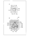
- FIG. 9 is an explanatory diagram showing an example of the cloning process by the navigation device.
- (A) to (C) are mesh data of two-dimensional matrix data (Y, X) of m rows and m columns in which identification information is assigned to each region.
- (A) shows the mesh data 900 to which the identification information is given for the first time after the map data division processing. That is, the mesh data 900 shown in (A) is the same as the mesh data shown in FIG.
- (B) shows the mesh data 910 after the cloning process (expansion) is performed on the mesh data 900 shown in (A).
- (C) shows the mesh data 920 after the cloning process (reduction) is performed on the mesh data 910 shown in (B).
- the vehicle reachable ranges 901, 911, and 921 generated by the plurality of regions to which reachable identification information is assigned are blacked out. Show.
- a missing point 902 (a white background in the reachable range 901 that is hatched) that is an unreachable region included in the reachable range 901 of the vehicle. Part) has occurred.
- the missing point 902 is a node that becomes a reachable point when a road for searching for a node and a link is narrowed down to reduce the load of the reachable point search process by the navigation device 400. This occurs when the number is reduced.
- the navigation apparatus 400 performs an expansion process of cloning on the mesh data 900 after the identification information is added.
- the identification information of one area adjacent to the area to which reachable identification information is assigned in the mesh data 900 after the identification information is given is changed to reachable identification information.
- the missing portion 902 generated in the reachable range 901 of the vehicle before the expansion process (after the identification information is given) disappears.
- the identification information of all areas adjacent to the outermost area of the reachable range 901 of the vehicle before the expansion process is changed to reachable identification information.
- the outer periphery of the reachable range 911 of the vehicle after the expansion process is one dot at a time so as to surround the outer periphery of each outermost area of the reachable range 901 of the vehicle before the expansion process every time the expansion process is performed. spread.
- the navigation device 400 performs a cloning reduction process on the mesh data 910.
- the identification information of one area adjacent to the area to which the unreachable identification information is assigned in the mesh data 910 after the expansion process is changed to the unreachable identification information.
- each area on the outermost periphery of the reachable range 911 of the vehicle after the expansion process becomes an area that cannot be reached by one dot every time the reduction process is performed, and the reachable range 911 of the vehicle after the expansion process is reached.
- the outer circumference shrinks.
- the outer periphery of the reachable range 921 of the vehicle after the reduction process is substantially the same as the outer periphery of the reachable range 901 of the vehicle before the expansion process.
- Navigation device 400 performs the above-described expansion process and reduction process the same number of times. Specifically, when the expansion process is performed twice, the subsequent reduction process is also performed twice. By equalizing the number of times of the expansion process and the reduction process, the identification information of almost all areas in the outer periphery of the reachable range of the vehicle that has been changed to the identification information that can be reached by the expansion process is restored to the original information by the reduction process. It can be changed to unreachable identification information. In this way, the navigation device 400 can remove the missing point 902 within the reachable range of the vehicle and generate the reachable range 921 of the vehicle that can clearly display the outer periphery.
- the navigation device 400 performs an opening process (a process of performing an expansion process after the reduction process) on the mesh data of the two-dimensional matrix data (Y, X), and generates a vehicle reachable range in which the outer periphery can be clearly displayed. May be.
- the navigation apparatus 400 performs an opening process as follows.
- FIG. 10 is an explanatory diagram showing an example of the opening process by the navigation device.
- FIGS. 10A to 10C are mesh data of two-dimensional matrix data (Y, X) of m rows and m columns in which identification information is assigned to each region.
- FIG. 10A shows mesh data 1000 after identification information is given.
- FIG. 10B shows mesh data 1010 after the opening process (reduction) with respect to FIG.
- FIG. 10C shows mesh data 1020 after the opening process (expansion) with respect to FIG.
- the vehicle reachable ranges 1001, 1011 and 1021 generated by a plurality of regions to which reachable identification information is assigned are blackened. Shown in a filled state.
- the mesh data 1000 after the identification information is added is opened.
- the isolated point 1002 can be removed.
- the navigation apparatus 400 performs an opening reduction process on the mesh data 1000 after the identification information is given.
- the identification information of one area adjacent to the area to which the unreachable identification information is added in the mesh data 1000 after the identification information is added is changed to the unreachable identification information.
- the isolated point 1002 generated in the reachable range 1001 of the vehicle before the reduction process (after the identification information is given) is removed.
- each area of the outermost periphery of the reachable range 1001 of the vehicle after the identification information is added becomes an area that cannot be reached by one dot every time the reduction process is performed, and the reachable range of the vehicle after the identification information is given
- the outer periphery of 1001 shrinks. Further, the isolated point 1002 generated in the reachable range 1001 of the vehicle after the identification information is given is removed.
- the navigation device 400 performs an opening expansion process on the mesh data 1010.
- the identification information of one area adjacent to the area to which the unreachable identification information is added in the mesh data 1010 after the reduction process is changed to the reachable identification information.
- the outer periphery of the reachable range 1021 of the vehicle after the expansion process is one dot at a time so as to surround the outer periphery of each outermost region of the reachable range 1011 of the vehicle after the reduction process every time the expansion process is performed. spread.
- the navigation device 400 performs the expansion process and the reduction process the same number of times as in the cloning process.
- the outer periphery of the reachable range 1011 of the vehicle shrunk by the reduction process is expanded, and the outer periphery of the vehicle reachable range 1021 after the reduction process is expanded before the reduction process.
- the navigation device 400 can generate the vehicle reachable range 1021 in which the isolated point 1002 does not occur and the outer periphery can be clearly displayed.
- the navigation device 400 of this embodiment extracts the contour of the reachable range of the vehicle based on the identification information given to the mesh data of the two-dimensional matrix data (Y, X) of m rows and m columns. Specifically, the navigation apparatus 400 extracts the outline of the reachable range of the vehicle using, for example, a Freeman chain code. More specifically, the navigation apparatus 400 extracts the outline of the reachable range of the vehicle as follows.
- FIG. 11 is an explanatory diagram schematically showing an example of vehicle reachable range extraction by the navigation device.
- FIG. 12 is an explanatory diagram schematically showing an example of mesh data after the vehicle reachable range is extracted by the navigation device.
- FIG. 11A shows numbers indicating the adjacent directions of the regions 1110 to 1117 adjacent to the region 1100 (hereinafter referred to as “direction index (chain code)”) and eight-direction arrows corresponding to the direction index.
- FIG. 11B shows mesh data 1120 of two-dimensional matrix data (Y, X) of h rows and h columns as an example.
- the areas 1121 to 1134 to which reachable identification information is assigned and the areas to which reachable identification information is enclosed surrounded by the areas 1121 to 1134 are illustrated by hatching.
- the direction index indicates the direction in which the line segment of the unit length is facing.
- the coordinates corresponding to the direction index are (X + dx, Y + dy).
- the direction index in the direction from the region 1100 toward the region 1110 adjacent to the lower left is “0”.
- the direction index in the direction from the region 1100 to the adjacent region 1111 is “1”.
- the direction index in the direction from the region 1100 toward the region 1112 adjacent to the lower right is “2”.
- the direction index in the direction from the region 1100 toward the region 1113 adjacent to the right is “3”.
- the direction index in the direction from the region 1100 toward the region 1114 adjacent to the upper right is “4”.
- the direction index in the direction from the region 1100 toward the adjacent region 1115 is “5”.
- the direction index in the direction from the region 1100 toward the region 1116 adjacent to the upper left is “6”.
- the direction index in the direction from the region 1100 toward the region 1117 adjacent to the left is “7”.
- the navigation device 400 searches the area to which the reachable identification information “1” adjacent to the area 1100 is assigned in the counterclockwise direction. In addition, the navigation device 400 determines the search start point of the area to which the reachable identification information adjacent to the area 1100 is assigned based on the previous direction index. Specifically, when the direction index from another area toward area 1100 is “0”, navigation device 400 has an area adjacent to the left of area 1100, that is, an area adjacent in the direction of direction index “7”. The search starts from 1117.
- the navigation device 400 is adjacent to the lower left, lower, lower right, right, upper right, upper left of the region 1100.
- the search is started from the matching regions, that is, the regions 1110 to 1116 adjacent in the directions of the direction indices “0”, “1”, “2”, “3”, “4”, “5”, “6”, respectively.
- the navigation apparatus 400 detects the reachable identification information “1” from any one of the areas 1110 to 1117 from the area 1100, the areas 1110 to 1117 in which the reachable identification information “1” is detected.
- the direction indices “0” to “7” corresponding to are written in the storage device in association with the area 1100.
- the navigation device 400 extracts the outline of the reachable range of the vehicle as follows. As shown in FIG. 11 (B), the navigation apparatus 400 first identifies identification that can be reached in units of rows from the region of the a row and the a column of the mesh data 1120 of the two-dimensional matrix data (Y, X) of the h row and the h column. Search for an area to which information is assigned.
- the navigation device 400 Since unreachable identification information is assigned to all the regions in the a-th row of the mesh data 1120, the navigation device 400 next changes the b-row and h-column regions from the b-row and a-column regions of the mesh data 1120. Search for identification information that can be reached toward the area. Then, after detecting the reachable identification information in the area 1121 in the b row and e column of the mesh data 1120, the navigation device 400 moves counterclockwise from the area 1121 in the b row and e column of the mesh data 1120, and reaches the reachable range of the vehicle. The region having the reachable identification information that becomes the outline of is searched.
- the navigation apparatus 400 since the navigation apparatus 400 has already searched for the area of b rows and d columns adjacent to the left of the area 1121, first, the identification that can be reached counterclockwise from the area 1122 adjacent to the lower left of the area 1121. Search whether there is an area having information. Then, the navigation device 400 detects the reachable identification information of the region 1122 and stores the direction index “0” in the direction from the region 1121 to the region 1122 in association with the region 1121 in the storage device.
- the navigation device 400 since the navigation device 400 has the previous direction index “0”, whether or not there is a region having reachable identification information counterclockwise from the region of c rows and c columns adjacent to the left of the region 1122. Search for.
- the navigation device 400 detects the reachable identification information of the adjacent region 1123 at the lower left of the region 1122, and stores the direction index “0” in the direction from the region 1122 to the region 1123 in association with the previous direction index. Store in the device.
- the navigation device 400 determines a search start point based on the previous direction index, and uses the direction index as a process for searching for whether there is an area having identification information that can be reached counterclockwise from the search start point. The process is repeated until the corresponding arrow returns to the area 1121. Specifically, navigation device 400 searches whether there is a region having reachable identification information counterclockwise from the region adjacent to the left of region 1122, and searches for the region 1124 adjacent to the lower left of region 1123. The reachable identification information is detected, and the direction index “1” is stored in the storage device in association with the previous direction index.
- the navigation device 400 searches for an area having identification information that can be reached counterclockwise from the search start point, and an area having reachable identification information 1124 to 1134 are sequentially detected. Then, every time the direction index is acquired, the navigation device 400 stores the direction index in association with the previous direction index.
- the navigation device 400 searches whether there is an area having reachable identification information in the counterclockwise direction from the area of row b and column f adjacent to the upper right of the area 1134, and the area adjacent to the area 1134.
- the reachable identification information 1121 is detected, and the direction index “5” is stored in the storage device in association with the previous direction index.
- the direction index “0” ⁇ “0” ⁇ “1” ⁇ “0” ⁇ “2” ⁇ “3” ⁇ “4” ⁇ “3” ⁇ “2” ⁇ “5” ⁇ “5” ⁇ “6” ⁇ “6” ⁇ “5” is stored in this order.
- the navigation device 400 sequentially searches the areas 1122 to 1134 having the reachable identification information adjacent to the area 1121 in the counterclockwise direction from the first detected area 1121 to acquire the direction index. Then, the navigation device 400 fills one region in the direction corresponding to the direction index from the region 1121, thereby, as shown in FIG. 12, the contour 1201 of the reachable range of the vehicle and the portion 1202 surrounded by the contour 1201 The mesh data having the reachable range 1200 of the vehicle is generated.
- the navigation device 400 may extract the outline of the reachable range of the vehicle based on the longitude and latitude information of the mesh data of the two-dimensional matrix data (Y, X) to which reachable identification information is assigned.
- the navigation apparatus 400 extracts the outline of the reachable range of the vehicle as follows.
- FIG. 13 is an explanatory diagram schematically showing another example of vehicle reachable range extraction by the navigation device.
- the mesh data 1300 of the two-dimensional matrix data (Y, X) of d rows and h columns as shown in FIG. 13 will be described as an example.
- the navigation device 400 searches the mesh data 1300 for the region to which the reachable identification information “1” is assigned. Specifically, the navigation device 400 first searches for identification information “1” that can be reached from the area of the a row and the a column to the area of the a row and the h column.
- the navigation device 400 Since unreachable identification information “0” is assigned to all the regions in the a-th row of the mesh data 1300, the navigation device 400 next moves the region from the b-th row to the b-th column. A region having identification information “1” that can be reached is searched. Then, the navigation apparatus 400 acquires the minimum longitude px1 and the minimum latitude py1 (upper left coordinates of the area 1301) of the area 1301 in the b row and c column having the reachable identification information “1”.
- the navigation apparatus 400 searches for an area having identification information “1” that can be reached from the area of b rows and d columns toward the area of b rows and h columns. Then, the navigation device 400 searches for a boundary between the area having the reachable identification information “1” and the area having the reachable identification information “0”, and b rows having the reachable identification information “1”.
- the maximum longitude px2 and the maximum latitude py2 (lower right coordinates of the region 1302) of the region 1302 in the f column are acquired.
- the navigation device 400 has a rectangular area whose apexes are the upper left coordinates (px1, py1) of the area 1301 of b rows and c columns and the lower right coordinates (px2, py2) of the area 1302 of b rows and f columns. Fill.
- the navigation device 400 searches the mesh data 1300 for the identification information “1” that can be reached from the b row g column to the b row h column area and further from the c row a column to the c row h column.
- the navigation apparatus 400 acquires the minimum longitude px3 and the minimum latitude py3 (upper left coordinates of the area 1303) of the area 1303 in the c row and d column having the reachable identification information “1”.
- the navigation device 400 searches for an area having identification information “1” that can be reached from the area of the c row and the e column toward the area of the c row and the h column. Then, the navigation device 400 searches for a boundary between the area having the reachable identification information “1” and the area having the reachable identification information “0”, and the c row having the reachable identification information “1”.
- the maximum longitude px4 and the maximum latitude py4 (lower right coordinates of the region 1304) of the region 1304 in the f column are acquired.
- the navigation device 400 has a rectangular area whose apexes are the upper left coordinates (px3, py3) of the area 1303 of c rows and d columns and the lower right coordinates (px4, py4) of the area 1304 of c rows and f columns. Fill.
- the navigation apparatus 400 searches for an area having identification information “1” that can be reached from the area of the c row and the g column to the area of the c row and the h column and further from the d row and the a column to the d row and the h column. .
- the navigation device 400 ends the process because the unreachable identification information “0” is assigned to all the areas from the c row and g column areas to the d row and h column.
- the reachable range of the vehicle and the reachable range of the vehicle are set.
- the contour can be acquired.
- the navigation device 400 generates the reachable range of the moving object based on the reachable node of the moving object searched based on the remaining energy amount of the vehicle, and causes the display 413 to display the reachable range.
- the navigation device 400 is mounted on an EV car will be described as an example.
- FIG. 14 is a flowchart showing an example of the procedure of image processing by the navigation device.
- the navigation apparatus 400 first acquires the current location (ofx, ofy) of the vehicle on which the navigation apparatus 400 is mounted, for example, via the communication I / F 415 (step S1401).
- the navigation apparatus 400 acquires the initial stored energy amount of the vehicle at the current location (ofx, ofy) of the vehicle, for example, via the communication I / F 415 (step S1402).
- the navigation apparatus 400 performs a reachable node search process (step S1403).
- the navigation apparatus 400 performs mesh data generation and identification information addition processing (step S1404).
- the navigation apparatus 400 extracts the outline of the reachable range of the vehicle (step S1405).
- the navigation device 400 displays the reachable range of the vehicle on the display 413 (step S1406).
- the reachable range of the moving object is displayed by the above one-time search, it is determined whether the air conditioner has been switched on / off (step S1407). If switching of the air conditioner ON / OFF is not detected (step S1407: No), the above process is terminated.
- the reachable range of the displayed moving body is enlarged or reduced in accordance with ON / OFF of the air conditioner ( In step S1408), the process ends.
- FIG. 15 is a flowchart illustrating an example of a procedure of estimated power consumption calculation processing by the navigation device. In the flowchart illustrated in FIG. 15, the process is performed in the reachable node search process in step S1403 described above.
- the navigation apparatus 400 first acquires traffic jam information such as probe data and traffic jam prediction data via the communication I / F 415 (step S1501). Next, the navigation apparatus 400 acquires the length of the link and the road type of the link (step S1502).
- the navigation device 400 calculates the travel time of the link based on the information acquired in steps S1501 and S1502 (step S1503).
- the travel time of the link is the time required for the vehicle to finish traveling on the link.
- the navigation apparatus 400 calculates the average link speed based on the information acquired in steps S1501 to S1503 (step S1504).
- the average speed of the link is an average speed when the vehicle travels on the link.
- the navigation device 400 acquires the altitude data of the link (step S1505).
- the navigation apparatus 400 acquires vehicle setting information (step S1506).
- the navigation device 400 uses the energy consumption estimation formula of any one of the above-described formulas (1) to (6) based on the information acquired in steps S1501 to S1506 to estimate the consumption at the link.
- the amount of power is calculated (step S1507), the total power consumed until reaching each node, and the required time are stored in association with each node (step S1508), and the processing according to this flowchart ends.
- FIGS. 16A and 16B are flowcharts illustrating an example of the procedure of reachable point search processing by the navigation device.
- the navigation apparatus 400 adds the node N (i) _j connected to the link L (i) _j closest to the search start point to the node candidates (step S1601).
- the search start point is the current point (ofx, ofy) of the vehicle acquired in step S1401 described above.
- the variables i and j are arbitrary numerical values.
- a link and a node closest to the search start point are a link L (1) _j and a node N (1) _j, respectively, and are further connected to the node N (1) _j.
- the variable j1 is an arbitrary numerical value and means that a plurality of links or nodes exist in the same hierarchy.
- the navigation apparatus 400 determines whether there are one or more node candidates (step S1602).
- step S1602 Yes
- the navigation apparatus 400 selects a node candidate having the minimum cumulative power consumption from the current point of the vehicle to the node candidate (step S1603). For example, the following processing will be described assuming that the navigation device 400 selects the node N (i) _j as the node candidate.
- the navigation apparatus 400 determines whether or not the cumulative power consumption from the current point of the vehicle to the node N (i) _j is less than or equal to the specified energy amount (step S1604).
- the designated energy amount is, for example, the remaining energy amount of the vehicle at the current location of the vehicle.
- the navigation apparatus 400 extracts all the links L (i + 1) _j connected to the node N (i) _j (step S1605).
- the navigation apparatus 400 selects one link L (i + 1) _j among the links L (i + 1) _j extracted in step S1605 (step S1606).
- the navigation apparatus 400 performs candidate determination processing for determining whether or not the one link L (i + 1) _j selected in step S1606 is a link candidate (steps S1607 and S1608).
- the navigation apparatus 400 performs a power consumption calculation process for the one link L (i + 1) _j (step S1609).
- the navigation apparatus 400 calculates the cumulative power consumption W (i + 1) _j up to the node N (i + 1) _j connected to the one link L (i + 1) _j (step S1610).
- the navigation apparatus 400 determines whether there is another processed route connected to the node N (i + 1) _j (step S1611).
- step S1611 If there is another route that has been processed (step S1611: Yes), the navigation apparatus 400 determines that the cumulative power consumption W (i + 1) _j from the current point of the vehicle to the node N (i + 1) _j is the cumulative amount of the other route. It is determined whether it is smaller than the power consumption (step S1612). When the accumulated power consumption is smaller than the other route (step S1612: Yes), the navigation device 400 causes the node N (i + 1) _j to accumulate the accumulated power consumption W from the current point of the vehicle to the node N (i + 1) _j. (I + 1) _j is set (step S1613).
- step S1611 when there is no other processed route (step S1611: No), the navigation apparatus 400 proceeds to step S1613.
- the navigation apparatus 400 determines whether or not the node N (i + 1) _j is a node candidate (step S1614). If it is not a node candidate (step S1614: No), the navigation apparatus 400 adds the node N (i + 1) _j to the node candidate (step S1615).
- step S1608 When one link L (i + 1) _j is not a link candidate (step S1608: No), the accumulated power consumption W (i + 1) _j from the current point of the vehicle to the node N (i + 1) _j is on another route. If the node N (i + 1) _j is a node candidate (step S1614: Yes), the navigation device 400 proceeds to step S1616.
- the navigation apparatus 400 determines whether or not the candidate determination process for all links L (i + 1) _j has been completed (step S1616).
- the candidate determination process for all links L (i + 1) _j is completed (step S1616: Yes)
- the node N (i) _j is excluded from the node candidates (step S1617), and the process returns to step S1602.
- the navigation apparatus 400 selects a node candidate having the minimum cumulative power consumption from the current location of the vehicle from the node candidates (step S1603).
- the node candidate selected in step S1603 is set as the next node N (i) _j, and the processes in and after step S1604 are performed.
- step S1616: No when the candidate determination process for all links L (i + 1) _j is not completed (step S1616: No), the process returns to step S1606.
- the navigation device 400 again selects another link L (i + 1) _j connected to the node N (i) _j, and the candidate determination process for all the links L (i + 1) _j connected to the same node candidate is performed.
- step S1616: Yes the processes from step S1607 to step S1615 are repeated.
- step S1602 If there is no one or more node candidates (step S1602: No), the cumulative power consumption from the current point of the vehicle to the node N (i) _j is larger than the specified energy amount (step S1604: No), the navigation device In step 400, the process according to the flowchart ends.
- FIG. 17 is a flowchart illustrating an example of a procedure of identification information addition processing by the navigation device.
- the flowchart in FIG. 17 is processing performed in step S1404 described above.
- the navigation apparatus 400 first acquires longitude / latitude information (x, y) of a reachable node (searchable point) (step S1801). Next, the navigation apparatus 400 acquires the maximum longitude x_max, the minimum longitude x_min, the maximum latitude y_max, and the minimum latitude y_min (step S1802).
- the navigation apparatus 400 determines the distance w1 from the current vehicle location (ofx, ofy) acquired in step S1401 to the maximum longitude x_max, the distance w2 to the minimum longitude x_min, the distance w3 to the maximum latitude y_max, and the minimum latitude.
- a distance w4 to y_min is calculated (step S1803).
- the navigation apparatus 400 converts the map data from the absolute coordinate system to the screen coordinate system using the magnification mag calculated in step S1805, and generates mesh data (X, Y) of m ⁇ m dots (step S1806). ).
- step S1806 the navigation device 400 adds reachable identification information to the mesh data (X, Y) including the reachable node, and cannot reach the mesh data (X, Y) that does not include the reachable node.
- the identification information is assigned.
- the navigation apparatus 400 removes the missing point of the mesh data (X, Y) corresponding to a bridge or a tunnel by performing a 1st identification information change process (step S1807).
- the navigation device 400 performs a second identification information change process (step S1808).
- the navigation apparatus 400 performs a third identification information change process (step S1809), and ends the process according to this flowchart.
- the second identification information changing process is a cloning expansion process.
- the third identification information change process is a cloning reduction process.
- the second identification information change process (step S1808) and the third identification information change process (step S1809) are performed after the first identification information change process (step S1807).
- the first identification information change process (step S1807) may be performed.
- FIG. 18 is a flowchart illustrating an example of a procedure of first identification information change processing by the navigation device.
- the flowchart in FIG. 18 is an example of the process performed in step S1807 described above. Specifically, when the identification information of each area corresponding to the entrance and exit of the bridge or tunnel is reachable identification information, the navigation device 400 detects the missing point generated in the area corresponding to the bridge or tunnel. Remove.
- the navigation apparatus 400 first acquires mesh data of two-dimensional matrix data of my rows and mx columns (step S1811). Next, the navigation apparatus 400 substitutes 1 for the variables i and j in order to search for the identification information of the region of i row and j column of the mesh data (steps S1812 and S1813). Next, the navigation apparatus 400 determines whether or not the area in the i-th row and j-th column of the mesh data is a bridge or tunnel entrance / exit (step S1814).
- the navigation apparatus 400 determines whether or not the identification information of the i-th row and j-th column region of the mesh data is “1”. (Step S1815). When the identification information of the area of i row and j column is “1” (step S1815: Yes), the navigation device 400 corresponds to the area of the i row and j column of the mesh data and the area of the other entrance of the bridge or tunnel Position (i1, j1) is acquired (step S1816).
- the navigation apparatus 400 determines whether or not the identification information of the area in the i1 row and j1 column of the mesh data is “1” (step S1817).
- the identification information of the area of i1 row j1 column is “1” (step S1817: Yes)
- the navigation apparatus 400 has all the sections on the section connecting the i row j column area and the i1 row j1 column area.
- the position information of the area is acquired (step S1818).
- the navigation apparatus 400 changes the identification information of each area acquired in step S1818 to “1” (step S1819). As a result, the missing point generated in the region corresponding to the bridge or tunnel connecting the region of i row and j column and the region of i1 row and j1 column is removed.
- the navigation apparatus 400 may advance to step S1820 without performing the process of step S1819, when the identification information of each area
- step S1814 when the region of i row and j column is not the entrance of the bridge or tunnel (step S1814: No), when the identification information of the region of i row and j column is not “1” (step S1815: No), and i1 row j1 If the identification information of the row area is not “1” (step S1817: NO), the navigation apparatus 400 proceeds to step S1820.
- the navigation apparatus 400 adds 1 to the variable j (step S1820), and determines whether the variable j exceeds the mx column (step S1821). If the variable j does not exceed the mx column (step S1821: No), the navigation apparatus 400 returns to step S1814 and repeats the subsequent processing. On the other hand, when the variable j exceeds the mx column (step S1821: Yes), the navigation apparatus 400 adds 1 to the variable i (step S1822), and determines whether the variable i exceeds the my row. (Step S1823).
- step S1823: No If the variable i does not exceed the my line (step S1823: No), the navigation device 400 returns to step S1813, and after substituting 1 for the variable j, the subsequent processing is repeated. On the other hand, when the variable i exceeds the my line (step S1823: Yes), the navigation apparatus 400 ends the process according to this flowchart. Thereby, the navigation apparatus 400 can remove all missing points on the bridge or tunnel included in the mesh data of the two-dimensional matrix data of my rows and mx columns.
- the navigation apparatus 400 determines again whether or not the region of the column i1 and j1 acquired as the other entrance / exit of the bridge or tunnel in step S1816 is the other entrance / exit of the bridge or tunnel (processing in step S1814). ) Is not necessary. Thereby, the navigation apparatus 400 can reduce the processing amount of a 1st identification information change process.
- FIGS. 19A and 19B are flowcharts illustrating an example of the procedure of the reachable range outline extraction process by the navigation device.
- the flowcharts of FIGS. 19A and 19B are an example of the process performed in step S1405 described above.
- the outline of reachable range outline extraction in the navigation apparatus 400 described above is the reachable range outline extraction process shown in the second part. is there.
- the navigation apparatus 400 first acquires mesh data of two-dimensional matrix data of my rows and mx columns (step S1901). Next, the navigation apparatus 400 acquires longitude / latitude information of each area of the mesh data acquired in step S1901 (step S1902).
- the navigation device 400 initializes the variable i and adds 1 to the variable i in order to search the identification information of the area of the i-th row and j-th column of the mesh data (steps S1903 and S1904).
- the navigation apparatus 400 determines whether or not the variable i exceeds the my row (step S1905).
- step S1905 When the variable i does not exceed the my line (step S1905: No), the navigation apparatus 400 initializes the variable j and adds 1 to the variable j (steps S1906 and S1907). Next, the navigation apparatus 400 determines whether or not the variable j exceeds the mx column (step S1908).
- the navigation apparatus 400 determines whether or not the identification information of the area of the i-th row and j-th column of the mesh data is “1” (step S1909). . If the identification information of the i-th row and j-th column region is “1” (step S1909: Yes), the navigation apparatus 400 acquires the upper left coordinates (px1, py1) of the i-th row and j-th column region of the mesh data (step S1909). S1910).
- the upper left coordinates (px1, py1) of the region of i row and j column are the minimum longitude px1 and the minimum latitude py1 of the region of i row and j column.
- the navigation apparatus 400 determines whether or not the variable j exceeds the mx column (step S1911).
- the navigation apparatus 400 acquires the lower right coordinates (px2, py2) of the region of the i row and j column of the mesh data (step S1912).
- the lower right coordinates (px2, py2) of the area of i row and j column are the maximum longitude px2 and the maximum latitude py2 of the area of i row and j column.
- the navigation device 400 sets the upper left coordinates (px1, py1) acquired in step S1910 and the lower right coordinates (px2, py2) acquired in step S1912 in the map data (step S1916). Then, the navigation device 400 fills a rectangular area having the upper left coordinates (px1, py1) and the lower right coordinates (px2, py2) as opposed vertices (step S1917), returns to step S1904, and repeats the subsequent processing. Do it.
- step S1911 when the variable j does not exceed the mx column (step S1911: Yes), the navigation apparatus 400 adds 1 to the variable j (step S1913), and the identification information of the region of the i-th row and j-th column of the mesh data is “ It is determined whether it is “1” (step S1914).
- step S1914 When the identification information of the i-th row and j-th column area is not “1” (step S1914: No), the navigation apparatus 400 acquires the lower right coordinates (px2, py2) of the i-th row j ⁇ 1 column region of the mesh data. (Step S1915), the process after step S1916 is performed.
- step S1914: Yes If the identification information of the area of i row and j column is “1” (step S1914: Yes), the process returns to step S1911, and the subsequent processing is repeated. If the variable i exceeds the my line (step S1905: Yes), the navigation device 400 ends the process according to this flowchart. When the variable j exceeds the mx column (step S1908: Yes), the process returns to step S1904, and the subsequent processing is repeated.
- FIG. 20 is an explanatory diagram schematically illustrating an example of acceleration applied to a vehicle traveling on a road having a gradient.
- the second term on the right side of the above equation (1) indicates the acceleration A accompanying the traveling of the vehicle and the combined acceleration C of the traveling direction component B of the gravitational acceleration g. Yes.
- the distance D of the section in which the vehicle travels is defined as the travel time T and the travel speed V.
- the error between the estimated power consumption and the actual power consumption is small in the region where the road gradient ⁇ is small, but is estimated in the region where the road gradient ⁇ is large.
- An error between the estimated power consumption and the actual power consumption increases. For this reason, in the navigation apparatus 400, estimation accuracy improves by estimating the fuel consumption in consideration of the road gradient, that is, the fourth information.
- the slope of the road on which the vehicle travels can be known using, for example, an inclinometer mounted on the navigation device 400. Further, when the inclinometer is not mounted on the navigation device 400, for example, road gradient information included in the map data can be used.
- traveling resistance generated in the vehicle will be described.
- the navigation device 400 calculates the running resistance by the following equation (11), for example.
- traveling resistance is generated in a moving body during acceleration or traveling due to road type, road gradient, road surface condition, and the like.
- FIG. 21 is an explanatory diagram illustrating an example of a display example after the reachable point search process by the navigation device.
- FIG. 22-1 is an explanatory diagram illustrating an example of a display example after the identification information providing process by the navigation device.
- FIG. 22-2 is an explanatory diagram showing an example of a display example after the first identification information changing process by the navigation device.
- FIG. 23 is an explanatory diagram showing an example of a display example after the cloning process (expansion) by the navigation device.
- FIG. 24 is an explanatory diagram illustrating an example of a display example after the cloning process (reduction) by the navigation device.
- the display 413 displays reachable points of a plurality of vehicles searched by the navigation device 400 together with the map data.
- the state of the display 413 illustrated in FIG. 21 is an example of information displayed on the display when the reachable point search process is performed by the navigation device 400. Specifically, this is a state in which the process of step S1403 of FIG. 14 has been performed.
- the map data is divided into a plurality of areas by the navigation device 400, and identification information indicating whether each area is reachable or unreachable is given based on the reachable point, as shown in FIG.
- the display 413 displays a reachable range 2200 of the vehicle based on reachable identification information. At this stage, there is a missing point that is an unreachable region within the reachable range 2200 of the vehicle.
- the vehicle reachable range 2200 includes, for example, areas corresponding to both entrances and exits of the Tokyo Bay Crossing Road (Tokyo Bay Aqua Line: registered trademark) 2210 that crosses Tokyo Bay. However, the vehicle reachable range 2200 includes only one region 2211 out of all the regions on the Tokyo Bay crossing road 2210.
- the first identification information changing process is performed by the navigation device 400, so that the missing points on the Tokyo Bay crossing road are removed as shown in FIG. 22-2, and the display 413 is displayed on the Tokyo Bay crossing road 2210.
- the reachable range 2220 including the entire area 2221 is displayed.
- the expansion processing of cloning is performed by the navigation device 400, thereby generating a reachable range 2300 of the vehicle from which the missing points are removed, as shown in FIG.
- the entire area 2221 on the Tokyo Bay crossing road is already included in the reachable range 2220 by the first identification information change process, the entire area 2310 on the Tokyo Bay crossing road is The vehicle reachable range 2300 is obtained.
- the reduction processing of cloning is performed by the navigation device 400, so that the outer periphery of the vehicle reachable range 2400 is substantially the same as the outer periphery of the vehicle reachable range 2200 before the cloning is performed, as shown in FIG. It becomes the size of.
- the boundary of all areas 2310 on the Tokyo Bay crossing road in FIG. 23 and the boundary of all areas 2410 on the Tokyo Bay crossing road in FIG. 24 are displayed as boundaries depending on the mesh data. It is displayed at the boundary of diagonal lines for easy.
- the outline of the reachable range 2400 of the vehicle can be displayed smoothly.
- the reachable range 2400 of the vehicle is displayed with a two-dimensional smooth surface 2402. Even after the cloning reduction process, the entire area 2410 on the Tokyo Bay crossing road is displayed as the vehicle reachable range 2400 or its outline 2401.
- FIG. 25-1 is a chart showing power consumption stored as information on each node
- FIG. 25-2 is a chart showing required time stored as information on each node.
- the map information is divided into mesh-like areas, and the accumulated energy consumption (total power consumption) [kWh] required to reach each area from the current position 2500 is stored.
- the required time [h] required to reach each area from the current position 2500 is also stored in the same manner.
- this mesh also stores the corresponding latitude and longitude on the map, and the above-described expansion / reduction processing and contour extraction processing are performed.
- the reduction ratio is used when the air conditioner is OFF when searching and the air conditioner is turned ON after the reachable range is displayed. This reduction ratio is based on the total power consumption and the required time stored in a mesh shape for all contour regions (pixels) x and y, and the following processing is performed when the air conditioner is switched from OFF to ON. .
- FIG. 26 is a diagram for explaining a specific example of calculation of the reduction ratio.
- An outline 2601 of the reachable range is described on the map information 2600 of the mesh.
- FIGS. 27A and 27B are diagrams for explaining image processing when the reachable range is reduced. As shown in FIG. 27A, for each area (pixel) of the outline 2601 of the reachable range on the map information 2600, the total power consumption when the air conditioner is OFF, the required time, and the total power consumption after the air conditioner is ON. The reduction rate is calculated based on
- the pixel 2702a after the distance from the current position 2700 to the pixel 2701a having the reduction rate of 75% is changed according to the reduction rate is set as the reachable range when the air conditioner is ON. Then, each pixel on the reachable range 2701 is changed in accordance with the respective reduction rate, and the reachable range when the air conditioner is ON is obtained. Thereby, the change of the reachable range with high accuracy in view of the time required to each pixel and the total power consumption can be obtained in a short time.
- FIG. 28 is a flowchart showing a procedure for reducing the reachable range. The entire process from search to display is shown. First, at the time of searching, the operating state of the air conditioner is detected (step S2801). If it is in the OFF state (step S2801: OFF), the search unit 103 searches all reachable nodes when the air conditioner is OFF based on the energy consumption calculated by the calculation unit 102 (step S2802).
- the dividing unit 104 creates mesh data from the latitude and longitude point sequences of reachable nodes (step S2803). Based on the reachable node information searched by the search unit 103, the dividing unit 104 stores the total power consumption required to reach each mesh and the time required from the current position (step S2804).
- the contour data calculation unit 106 extracts the contour of the reachable range of the moving object from the mesh data using the identification information given by the grant unit 105 (step S2805). Then, the total power consumption and the required time in the area (pixel) constituting the contour of the mesh data are stored (step S2806). Then, the display control unit 108 displays the reachable range on the display unit 110 in an amoeba shape with the current position as the approximate center (step S2807), and ends the above processing.
- step S2801 when the air conditioner is switched off after searching, the process of steps S2801 to S2807 is performed and the reachable range is displayed on the display unit 110 (step S2801). : ON), the following processing is performed.
- the calculation unit 102 obtains a change in power consumption when the air conditioner is turned on based on the total power consumption stored in advance and the required time from the mesh on each contour of the reachable range (step S2808).
- the calculation unit 102 obtains a reduction rate from the center for each pixel constituting each contour (step S2809).
- the enlargement / reduction unit 107 reduces the reachable range based on the calculated reduction rate.
- the reduced reachable range is displayed on the display unit 110 by the display control unit 108 (step S2810), and the above processing ends.
- the processing time (Tsearch) during the search from step S2802 to step S2807 takes about 20 seconds, but the reduction processing time (Tmesh) from step S2808 to step S2810 can be about 1 sec. In this way, even when the air conditioner is turned on after the search and the process of reducing the reachable range is necessary, the search is not necessary again, and the reachable range is reduced by image processing, so the processing time is shortened. You can do it in time.
- the enlargement ratio is used when the air conditioner is ON during the search and the air conditioner is turned OFF after the reachable range is displayed.
- This enlargement ratio is the following processing when the air conditioner is switched from ON to OFF based on the total power consumption and the required time stored in a mesh shape for all contour regions (pixels) x and y. .
- FIG. 29 is a diagram illustrating a specific example of calculation of the enlargement ratio.
- An outline 2601 of the reachable range is described on the map information 2600 of the mesh.
- the region of pixel (x, y) (5, 3) when the fuel efficiency coefficient k1 is 0.5, the total power consumption when the air conditioner is ON is 12 [kW], and the required time is 8 [h]. And In this case, the total power consumption after the air conditioner is turned off is 12 [kW] ⁇ 8 [h] ⁇ 0.5 [kWh].
- FIG. 30 is a flowchart showing a procedure for expanding the reachable range. The entire process from search to display is shown.
- the operating state of the air conditioner is detected (step S3001). If it is in the ON state (step S3001: ON), the search unit 103 searches all reachable nodes when the air conditioner is ON based on the energy consumption calculated by the calculation unit 102 (step S3002).
- the dividing unit 104 creates mesh data from the latitude and longitude point sequences of reachable nodes (step S3003). Based on the reachable node information searched by the search unit 103, the dividing unit 104 stores the total power consumption required to reach each mesh and the time required from the current position (step S3004).
- the contour data calculation unit 106 extracts the contour of the reachable range of the moving object from the mesh data using the identification information given by the grant unit 105 (step S3005). Then, the total power consumption and the required time in the area (pixel) constituting the contour of the mesh data are stored (step S3006). Then, the display control unit 108 displays the reachable range on the display unit 110 in an amoeba shape with the current position as the approximate center (step S3007), and ends the above processing.
- step S3001 when the air conditioner is turned on at the time of the search and the air conditioner is switched to OFF after performing the processing of step S3001 to step S3007 and displaying the reachable range on the display unit 110 (step S3001). : OFF), the following processing is performed.
- the calculation unit 102 obtains a change in power consumption when the air conditioner is turned off based on the total power consumption stored in advance and the required time from the mesh on each contour of the reachable range (step S3008).
- the calculation unit 102 obtains an enlargement rate from the center for each pixel constituting each contour (step S3009). Then, the enlargement / reduction unit 107 expands the reachable range based on the calculated enlargement rate. The enlarged reachable range is displayed on the display unit 110 by the display control unit 108 (step S3010), and the above processing is terminated.
- the processing time (Tsearch) at the time of searching in steps S3002 to S3007 takes about 20 seconds, but the reduction processing time (Tmesh) in steps S3008 to S3010 is about 1 sec.
- search is not necessary again, and the reachable range is expanded by image processing, so the processing time is shortened. You can do it in time.
- FIG. 31 is a chart for explaining setting of the fuel consumption coefficient in consideration of temperature dependency.
- the variable is one outside air temperature
- FIG. 32 is a chart for explaining the setting of the fuel consumption coefficient corresponding to the energy consumption due to the difference between air conditioning cooling and heating. More specifically, the fuel efficiency coefficient k1 is as follows. k1 ⁇
- the difference between the set temperature and the outside air temperature is the same for both cooling and heating.
- the outside air temperature during heating is 18 [° C.]
- the set temperature is 28 ° C. (difference 10 [° C.])
- the outside air temperature during cooling is 35 [° C.]
- the set temperature is 25 ° C. (difference 10). [° C.]).
- the degree of change of the fuel efficiency coefficient k1 can be set by using ⁇ which is different between cooling and heating operations as shown in the figure (in the example shown, 1.2 during heating and 0.8 during cooling). This makes it possible to obtain a more accurate fuel efficiency coefficient including the difference in energy consumption during cooling and heating of the air conditioner.
- FIG. 33 is a diagram for explaining the reachable range for each set temperature.
- FIG. 34 is a flowchart showing a procedure for changing the reachable range by changing the set temperature of the air conditioner.
- a processing example corresponding to FIG. 33 will be described in which the reachable range is reduced when the air conditioner is OFF during the search and the subsequent air conditioner is turned ON at a predetermined set temperature.
- step S3401 the operating state of the air conditioner is detected (step S3401). If it is in the OFF state (step S3401: OFF), the search unit 103 searches all reachable nodes when the air conditioner is OFF based on the energy consumption calculated by the calculation unit 102 (step S3402).
- the dividing unit 104 creates mesh data from the latitude and longitude point sequences of reachable nodes (step S3403).
- the dividing unit 104 stores the total power consumption required to reach each mesh and the time required from the current position based on the reachable node information searched by the search unit 103.
- the contour data calculation unit 106 extracts the contour of the reachable range of the moving object from the mesh data using the identification information given by the grant unit 105 (step S3404). And the total power consumption and required time in the area
- the display control unit 108 displays the reachable range on the display unit 110 in an amoeba shape with the current position as the approximate center (step S3405), and ends the above processing.
- step S3401 when the air conditioner is switched off after searching, the process of steps S3401 to S3405 is performed and the reachable range is displayed on the display unit 110 (step S3401). : ON), the following processing is performed.
- the acquisition unit 101 acquires the set temperature of the air conditioner (step S3406), and thereafter performs processing for each of the set temperatures A to C of the air conditioner.
- the calculation unit 102 turns on the air conditioner based on the total power consumption and the required time stored in advance from the mesh on each contour of the reachable range, the outside air temperature, and the set temperature A of the air conditioner.
- a change in power consumption is determined in the case of (step S3407).
- the calculation unit 102 obtains a reduction rate from the center for each pixel constituting each contour (step S3408).
- the enlargement / reduction unit 107 reduces the reachable range based on the calculated reduction rate.
- the reduced reachable range is displayed on the display unit 110 by the display control unit 108 (step S3409), and the above processing ends.
- the calculation unit 102 turns on the air conditioner based on the total power consumption and the required time, the outside air temperature, and the set temperature B of the air conditioner that are stored in advance from the mesh on each contour of the reachable range. A change in power consumption in the case of setting is obtained (step S3410).
- the calculation unit 102 obtains a reduction rate from the center for each pixel constituting each contour (step S3411).
- the enlargement / reduction unit 107 reduces the reachable range based on the calculated reduction rate.
- the reduced reachable range is displayed on the display unit 110 by the display control unit 108 (step S3412), and the above processing ends.
- the calculation unit 102 turns on the air conditioner based on the total power consumption and the required time, the outside air temperature, and the set temperature C of the air conditioner that are stored in advance from the mesh on each contour of the reachable range. A change in power consumption in the case of setting is obtained (step S3413).
- the calculation unit 102 obtains a reduction rate from the center for each pixel constituting each contour (step S3414).
- the enlargement / reduction unit 107 reduces the reachable range based on the calculated reduction rate.
- the reduced reachable range is displayed on the display unit 110 by the display control unit 108 (step S3415), and the above processing ends.
- the processing time (Tsearch) at the time of searching in steps S3402 to S3405 takes about 20 seconds, but the set temperatures A to C after the air conditioner is switched on (steps S3407 to S3409, steps S3410 to S3412, and step S3413).
- Step S3415) Another reduction processing time (Tmesh) is about 1 sec. In this way, even when the air conditioner is turned on at a predetermined set temperature after the search and the process of reducing the reachable range is necessary, the search is not required again, and the reachable range is reduced by image processing.
- the processing time can be shortened. Not only the above processing example, but also when the air conditioner at the time of search is ON and the air conditioner is switched OFF after the search, the necessary reachable range expansion process can be easily performed.
- the map information is divided into a plurality of areas, and it is searched whether or not each mobile area can reach each area, and each mobile area can reach or reach each area. Reachable or unreachable identification information for identifying the impossibility is given. And the navigation apparatus 400 produces
- the navigation device 400 converts a plurality of areas obtained by dividing the map information into image data, and assigns identification information indicating that each of the plurality of areas is reachable or unreachable, and then performs an expansion process of cloning. For this reason, the navigation apparatus 400 can remove the missing point within the reachable range of the moving body.
- the navigation device 400 converts a plurality of areas obtained by dividing the map information into image data, and assigns identification information indicating that each of the plurality of areas is reachable or unreachable, and then performs an opening reduction process. For this reason, the navigation apparatus 400 can remove the isolated points in the reachable range of the moving object.
- the navigation device 400 can remove missing points or isolated points from the reachable range of the moving body, and thus can display the travelable range of the moving body on a two-dimensional smooth surface and in an easy-to-read manner. . Further, the navigation device 400 extracts the outline of mesh data generated by dividing the map information into a plurality of regions. For this reason, the navigation apparatus 400 can display the outline of the reachable range of a moving body smoothly.
- the navigation device 400 narrows down the road for searching for the reachable point of the moving object, and searches for the reachable point of the moving object. For this reason, the navigation apparatus 400 can reduce the processing amount at the time of searching the reachable point of a moving body. Even if the number of reachable reachable points is reduced by narrowing down the road to search for the reachable points of the mobile object, the expansion process of cloning is performed as described above, so that the reachable range of the mobile object is within the reachable range. The resulting defect point can be removed. Therefore, the navigation apparatus 400 can reduce the processing amount for detecting the reachable range of a mobile body. In addition, the navigation device 400 can display the travelable range of the moving body in a two-dimensional smooth surface in an easy-to-see manner.
- the reachable range can be easily changed.
- the energy consumption from the current position of the moving object and the required time are stored together with the latitude and longitude, and the outline of the reachable range based on the ON / OFF switching of the air conditioner
- the amount of energy consumed and the required time are read out, and the reachable range is expanded or reduced by image processing.
- the reachable range can be changed by image processing corresponding to the outside air temperature and the set temperature of the air conditioner, and the reachable range can be changed more finely according to the energy consumed by the air conditioner.
- FIG. 35 is a block diagram of an example of a functional configuration of the image processing system according to the second embodiment.
- a functional configuration of the image processing system 3500 according to the second embodiment will be described.
- An image processing system 3500 according to the second embodiment includes a server 3510 and a terminal 3520.
- An image processing system 3500 according to the second embodiment includes a server 3510 and a terminal 3520 having the functions of the image processing apparatus 100 according to the first embodiment.
- the server 3510 generates information to be displayed on the display unit 110 by the terminal 3520 mounted on the mobile object. Specifically, the server 3510 detects information related to the reachable range of the moving object and transmits the information to the terminal 3520.
- the terminal 3520 may be mounted on a mobile object, may be used as a mobile terminal in the mobile object, or may be used outside the mobile object as a mobile terminal. Terminal 3520 receives information regarding the reachable range of the moving object from server 3510.
- the server 3510 includes a calculation unit 102, a search unit 103, a division unit 104, a grant unit 105, a contour data calculation unit 106, an enlargement / reduction unit 107, a server reception unit 3511, and a server transmission unit 3512.
- the terminal 3520 includes an acquisition unit 101, a display control unit 108, a terminal reception unit 3521, and a terminal transmission unit 3522.
- the server reception unit 3511 receives information transmitted from the terminal 3520. Specifically, for example, the server reception unit 3511 receives information regarding a mobile unit from a terminal 3520 connected to a communication network such as a public line network, a mobile phone network, DSRC, LAN, and WAN via a radio.
- the information regarding the moving body is information regarding the current position of the moving body and information regarding the initial amount of energy that is the amount of energy held by the moving body at the current position of the moving body.
- Information received by the server reception unit 3511 is information referred to by the calculation unit 102.
- the server transmission unit 3512 uses the plurality of areas obtained by dividing the map information to which the reachable identification information for identifying that the moving body is reachable by the assigning unit 105 as a reachable range of the moving body as a terminal 3520. Specifically, for example, the server transmission unit 3512 transmits information to a terminal 3520 connected to a communication network such as a public line network, a mobile phone network, a DSRC, a LAN, and a WAN via a radio.
- a communication network such as a public line network, a mobile phone network, a DSRC, a LAN, and a WAN via a radio.
- Terminal 3520 is connected to server 3510 in a communicable state via, for example, an information communication network of a mobile terminal or a communication unit (not shown) provided in its own device.
- terminal receiving unit 3521 receives information from server 3510. Specifically, the terminal receiving unit 3521 divides the map information, which is divided into a plurality of regions, and each region is provided with identification information that is reachable or unreachable based on the reachable point of the mobile object. Receive. More specifically, for example, the terminal reception unit 3521 receives information from a server 3510 connected to a communication network such as a public line network, a mobile phone network, DSRC, LAN, and WAN via a wireless connection.
- a communication network such as a public line network, a mobile phone network, DSRC, LAN, and WAN via a wireless connection.
- the terminal transmission unit 3522 transmits information regarding the moving object acquired by the acquisition unit 101 to the server 3510. Specifically, for example, the terminal transmission unit 3522 transmits information related to the mobile unit to a server 3510 that is connected to a communication network such as a public line network, a mobile phone network, DSRC, LAN, and WAN via a radio.
- a communication network such as a public line network, a mobile phone network, DSRC, LAN, and WAN via a radio.
- Image processing by the image processing system 3500 includes estimated energy consumption calculation processing, reachable point search processing, identification information addition processing, contour data calculation, and enlargement / reduction processing among the image processing performed by the image processing apparatus 100 according to the first embodiment. It is performed by the server 3510. Specifically, in the flowchart of FIG. 2, the terminal 3520 performs the process of step S ⁇ b> 201 and transmits the information acquired in step S ⁇ b> 201 to the server 3510.
- the server 3510 receives information from the terminal 3520.
- the server 3510 performs steps S202 to S207 based on the information received from the terminal 3520, and transmits the information acquired in step S207 to the terminal 3520.
- the terminal 3520 receives information from the server 3510.
- Terminal 3520 performs step S208 based on the information received from server 3510.
- the terminal 3520 determines the process of step S209, and if the air conditioner is not switched, the process according to this flowchart is terminated. If the air conditioner is switched, the process of step S210 is performed, and the process according to this flowchart is terminated.
- the image processing system 3500 and the image processing method according to the second embodiment can obtain the same effects as those of the image processing apparatus 100 and the image processing method according to the first embodiment.
- FIG. 36 is a block diagram of an example of a functional configuration of the image processing system according to the third embodiment.
- a functional configuration of the image processing system 3600 according to the third embodiment will be described.
- An image processing system 3600 according to the third embodiment includes a first server 3610, a second server 3620, a third server 3630, and a terminal 3640.
- the first server 3610 has the function of the calculation unit 102 of the image processing apparatus 100 of the first embodiment
- the second server 3620 has the function of the search unit 103 of the image processing apparatus 100 of the first embodiment.
- the third server 3630 includes the functions of the dividing unit 104, the adding unit 105, the contour data calculating unit 106, and the enlargement / reduction unit 107 of the image processing apparatus 100 according to the first embodiment, and the acquisition of the image processing apparatus 100 according to the first embodiment.
- the terminal 3640 includes the functions of the unit 101 and the display control unit 108.
- the terminal 3640 has the same configuration as the terminal 3520 of the second embodiment. Specifically, the terminal 3640 includes an acquisition unit 101, a display control unit 108, a terminal reception unit 3641, and a terminal transmission unit 3642. Terminal reception unit 3641 has the same configuration as terminal reception unit 3521 of the second embodiment. Terminal transmission unit 3642 has the same configuration as terminal transmission unit 3522 of the second embodiment.
- the first server 3610 includes a calculation unit 102, a first server reception unit 3611, and a first server transmission unit 3612.
- the second server 3620 includes a search unit 103, a second server reception unit 3621, and a second server transmission unit 3622.
- the third server 3630 includes a dividing unit 104, a granting unit 105, a contour data calculating unit 106, an expansion / contraction unit 107, a third server receiving unit 3631, and a third server transmitting unit 3632.
- the first server reception unit 3611 receives the information transmitted from the terminal 3640. Specifically, for example, the first server reception unit 3611 receives information from the terminal transmission unit 3642 of the terminal 3640 that is wirelessly connected to a communication network such as a public line network, a mobile phone network, DSRC, LAN, and WAN. Receive.
- the information received by the first server reception unit 3611 is information referred to by the calculation unit 102.
- the first server transmission unit 3612 transmits the information calculated by the calculation unit 102 to the second server reception unit 3621. Specifically, the first server transmission unit 3612 transmits information to a second server reception unit 3621 connected to a public network, a mobile phone network, a communication network such as a DSRC, a LAN, and a WAN via a radio. Alternatively, the information may be transmitted to the second server reception unit 3621 connected by wire.
- the second server reception unit 3621 receives the information transmitted by the terminal transmission unit 3642 and the first server transmission unit 3612.
- the second server reception unit 3621 includes a first server transmission unit 3612 and a terminal transmission unit that are wirelessly connected to a communication network such as a public line network, a mobile phone network, DSRC, LAN, and WAN.
- Information from 3642 is received.
- the second server reception unit 3621 may receive information from the first server transmission unit 3612 connected by wire.
- the information received by the second server reception unit 3621 is information referred to by the search unit 103.
- the second server transmission unit 3622 transmits the information searched by the search unit 103 to the third server reception unit 3631. Specifically, for example, the second server transmission unit 3622 transmits information to a third server reception unit 3631 that is connected to a communication network such as a public line network, a mobile phone network, DSRC, LAN, and WAN via a radio. Alternatively, the information may be transmitted to the third server reception unit 3631 connected by wire.
- a communication network such as a public line network, a mobile phone network, DSRC, LAN, and WAN via a radio.
- the information may be transmitted to the third server reception unit 3631 connected by wire.
- the third server reception unit 3631 receives the information transmitted by the terminal transmission unit 3642 and the second server transmission unit 3622.
- the third server reception unit 3631 includes a second server transmission unit 3622 and a terminal transmission unit that are wirelessly connected to a communication network such as a public line network, a mobile phone network, DSRC, LAN, and WAN.
- Information from 3642 may be received.
- the third server reception unit 3631 may receive information from the second server transmission unit 3622 connected by wire.
- Information received by the second server reception unit 3621 is information referred to by the division unit 104.
- the third server transmission unit 3632 transmits the information generated by the grant unit 105 to the terminal reception unit 3641. Specifically, for example, the third server transmission unit 3632 transmits information to a terminal reception unit 3641 that is connected to a communication network such as a public line network, a mobile phone network, DSRC, LAN, and WAN via a radio.
- a communication network such as a public line network, a mobile phone network, DSRC, LAN, and WAN via a radio.
- the first server 3610 performs estimated energy consumption calculation processing
- the second server 3620 performs reachable point search processing.
- the third server 3630 performs the identification information adding process.
- the terminal 3640 performs the process of step S201 and transmits the information acquired in step S201 to the first server 3610.
- the first server 3610 receives information from the terminal 3640.
- the first server 3610 performs the processing of steps S202 and S203 based on the information received from the terminal 3640, and transmits the information calculated in step S203 to the second server 3620.
- the second server 3620 receives information from the first server 3610.
- the second server 3620 performs the process of step S204 based on the information received from the first server 3610, and transmits the information searched in step S204 to the third server 3630.
- the third server 3630 receives information from the second server 3620.
- the third server 3630 performs the processing of step S206 to step S207 based on the information from the second server 3620, and transmits the information generated in step S208 to the terminal 3640.
- the terminal 3640 receives information from the third server 3630. Then, the terminal 3640 performs step S208 based on the information received from the third server 3630.
- the terminal 3640 determines the process of step S209. If the air conditioner is not switched, the process according to this flowchart is terminated. If the air conditioner is switched, the process of step S210 is performed, and the process according to this flowchart is terminated.
- the image processing system 3600 and the image processing method according to the third embodiment can obtain the same effects as the image processing apparatus 100 and the image processing method according to the first embodiment.
- FIG. 37 is an explanatory diagram of an example of a system configuration of the image processing apparatus according to the second embodiment.
- the image processing system 3700 includes a navigation device 3710, a server 3720, and a network 3740 that are mounted on the vehicle 3730.
- Navigation device 3710 is mounted on vehicle 3730.
- the navigation device 3710 transmits information on the current location of the vehicle and information on the initial stored energy amount to the server 3720.
- the navigation device 3710 displays the information received from the server 3720 on the display and notifies the user.
- Server 3720 receives information on the current location of the vehicle and information on the initial stored energy amount from navigation device 3710.
- Server 3720 generates information related to the reachable range of vehicle 3730 based on the received vehicle information.
- the hardware configuration of the server 3720 and the navigation device 3710 is the same as the hardware configuration of the navigation device 400 of the first embodiment. Further, the navigation device 3710 only needs to have a hardware configuration corresponding to a function of transmitting vehicle information to the server 3720 and a function of receiving information from the server 3720 and notifying the user.
- the image processing system 3700 uses the navigation device 3710 mounted on the vehicle as the terminal 3640 of the third embodiment, and the functional configuration of the server 3720 is distributed to the first to third servers 3610 to 3630 of the third embodiment. It is good.
- the image processing method described in the present embodiment can be realized by executing a program prepared in advance on a computer such as a personal computer or a workstation.
- This program is recorded on a computer-readable recording medium such as a hard disk, a flexible disk, a CD-ROM, an MO, and a DVD, and is executed by being read from the recording medium by the computer.
- the program may be a transmission medium that can be distributed via a network such as the Internet.
Landscapes
- Engineering & Computer Science (AREA)
- Radar, Positioning & Navigation (AREA)
- Remote Sensing (AREA)
- Automation & Control Theory (AREA)
- Physics & Mathematics (AREA)
- General Physics & Mathematics (AREA)
- Navigation (AREA)
Description
この発明は、移動体の残存エネルギー量に基づいて移動体の到達可能範囲を生成する画像処理装置、画像処理管理装置、端末および画像処理方法に関する。ただし、この発明の利用は、画像処理装置、画像処理管理装置、端末および画像処理方法に限らない。
従来、移動体の現在地点に基づいて、移動体の到達可能範囲を生成する処理装置が知られている(たとえば、下記特許文献1参照。)。下記特許文献1では、移動体の現在地点を中心に地図上の全方位を放射状に分割し、分割領域ごとに移動体の現在地点から最も遠い到達可能な交差点を地図情報のノードとして取得する。そして、取得した複数のノードを結んで得られるベジュ曲線を移動体の到達可能範囲として表示している。
また、移動体のバッテリー残容量および電力消費量に基づいて、各道路における移動体の現在地点からの到達可能範囲を生成する処理装置が知られている(たとえば、下記特許文献2参照。)。下記特許文献2では、移動体の現在地点に接続する複数の道路において移動体の電力消費量を算出し、移動体のバッテリー残容量および電力消費量に基づいて各道路における移動体の走行可能距離を算出する。そして、移動体の現在地点と、当該現在地点から走行可能距離だけ離れた移動体の複数の到達可能地点とを地図情報のノードとして取得し、複数のノードを結んで得られる線分の集合体を移動体の到達可能範囲として表示している。
しかしながら、上述した特許文献1の技術では、移動体の現在地点を中心に各方位における移動体から最も遠い到達地点のみを取得しているので、移動体の到達可能範囲の輪郭しか得られない。このため、移動体の現在地点と移動体から最も遠い到達地点との間に、海や湖など移動体が走行することのできない領域が含まれていたとしても、この移動体が走行することのできない領域を除外して移動体の到達可能範囲を取得することができないという問題点が一例として挙げられる。
また、上述した特許文献2の技術では、移動体の到達可能範囲として道路のみを取得しているので、道路以外の範囲を移動体の到達可能範囲に含めることができない。また、移動体の到達可能範囲が移動体の走行可能な道路に沿った線分の集合体で表示されるので、到達可能範囲の輪郭を取得することができない。このため、移動体の到達可能範囲を見やすく、かつ漏れなく表示することが困難であるという問題点が一例として挙げられる。
また、特許文献1,2のいずれにおいても、移動体が消費するエネルギーの変化があると、移動体の到達範囲が変化することになるため、再度探索をおこなって消費エネルギー、および到達可能範囲を再計算する等の処理が必要となった。たとえば、移動体に備えられた装備品としてエアコンがあり、このエアコンのON/OFFにより消費するエネルギー量が変化するため、エアコンのON/OFFごとに再計算が必要となるという問題点が一例として挙げられる。
上述した課題を解決し、目的を達成するため、請求項1の発明にかかる画像処理装置は、移動体の到達可能範囲に関する情報を処理する画像処理装置であって、前記移動体の現在位置に関する情報、前記移動体が保有するエネルギー量に関する情報、および、前記移動体が所定区間を走行する際に消費するエネルギー量を示す推定エネルギー消費量に基づき、前記移動体の複数の到達可能な領域を含む到達可能範囲を算出する到達可能範囲算出手段と、前記移動体に備えられた装備品の動作状態が変化したとき、当該装備品が消費するエネルギー量の変化分に対応した拡縮率を算出し、当該拡縮率に基づき前記到達可能範囲の輪郭を拡大または縮小させる拡縮手段と、前記拡縮手段により拡大または縮小された前記到達可能範囲の輪郭を表示手段に表示させる表示制御手段と、を備えることを特徴とする。
また、請求項5の発明にかかる画像処理管理装置は、移動体の到達可能範囲に関する情報を処理する画像処理管理装置であって、前記移動体の現在位置に関する情報、前記移動体が保有するエネルギー量に関する情報、および、前記移動体に備えられた装備品の動作状態の変化に関する情報を受信する受信手段と、前記移動体の現在位置に関する情報、前記移動体が保有するエネルギー量に関する情報、および、前記移動体が所定区間を走行する際に消費するエネルギー量を示す推定エネルギー消費量に基づき、前記移動体の複数の到達可能な領域を含む到達可能範囲を算出する到達可能範囲算出手段と、前記移動体に備えられた装備品の動作状態が変化したとき、当該装備品が消費するエネルギー量の変化分に対応した拡縮率を算出し、当該拡縮率に基づき前記到達可能範囲の輪郭を拡大または縮小させる拡縮手段と、前記拡縮手段により拡大または縮小された前記到達可能範囲の輪郭を送信する送信手段と、を備えることを特徴とする。
また、請求項6の発明にかかる端末は、移動体の到達可能範囲に関する情報を処理する端末であって、前記移動体の現在位置に関する情報、前記移動体が保有するエネルギー量に関する情報、および、前記移動体に備えられた装備品の動作状態の変化に関する情報を送信する送信手段と、前記送信手段により送信された前記移動体の現在位置に関する情報、および、前記移動体が保有するエネルギー量に関する情報、および、前記移動体が所定区間を走行する際に消費するエネルギー量を示す推定エネルギー消費量に基づき、前記移動体の複数の到達可能な領域を含む到達可能範囲を算出し、前記移動体に備えられた装備品の動作状態が変化したとき、当該装備品が消費するエネルギー量の変化分に対応した拡縮率を算出し、当該拡縮率に基づき拡大または縮小された前記到達可能範囲の輪郭を受信する受信手段と、前記受信手段により受信された拡大または縮小された前記到達可能範囲の輪郭を表示手段に表示させる表示制御手段と、を備えることを特徴とする。
また、請求項7の発明にかかる画像処理方法は、移動体の到達可能範囲に関する情報を処理する画像処理装置の画像処理方法であって、前記移動体の現在位置に関する情報、前記移動体が保有するエネルギー量に関する情報、および、前記移動体が所定区間を走行する際に消費するエネルギー量を示す推定エネルギー消費量に基づき、前記移動体の複数の到達可能な領域を含む到達可能範囲を算出する到達可能範囲算出工程と、前記移動体に備えられた装備品の動作状態が変化したとき、当該装備品が消費するエネルギー量の変化分に対応した拡縮率を算出し、当該拡縮率に基づき前記到達可能範囲の輪郭を拡大または縮小させる拡縮工程と、前記拡縮工程により拡大または縮小された前記到達可能範囲の輪郭を表示手段に表示させる表示制御工程と、を含むことを特徴とする。
以下に添付図面を参照して、この発明にかかる画像処理装置、画像処理管理装置、端末および画像処理方法の好適な実施の形態を詳細に説明する。
(実施の形態1)
図1は、実施の形態1にかかる画像処理装置の機能的構成の一例を示すブロック図である。実施の形態1にかかる画像処理装置100は、移動体の残存エネルギー量に基づいて探索された移動体の到達可能地点に基づいて移動体の到達可能範囲を生成し表示部110に表示させる。また、画像処理装置100は、取得部101、算出部102、探索部103、分割部104、付与部105、輪郭データ算出部106、拡縮部107、表示制御部108によって構成される。
図1は、実施の形態1にかかる画像処理装置の機能的構成の一例を示すブロック図である。実施の形態1にかかる画像処理装置100は、移動体の残存エネルギー量に基づいて探索された移動体の到達可能地点に基づいて移動体の到達可能範囲を生成し表示部110に表示させる。また、画像処理装置100は、取得部101、算出部102、探索部103、分割部104、付与部105、輪郭データ算出部106、拡縮部107、表示制御部108によって構成される。
ここで、エネルギーとは、たとえば、EV(Electric Vehicle)車などの場合、電気などに基づくエネルギーであり、HV(Hybrid Vehicle)車、PHV(Plug-in Hybrid Vehicle)車などの場合は電気などに基づくエネルギーおよび、たとえばガソリンや軽油、ガスなどに基づくエネルギーである。また、エネルギーとは、たとえば燃料電池車の場合、電気などに基づくエネルギーおよび、たとえば水素や水素原料になる化石燃料などである(以下、EV車、HV車、PHV車、燃料電池車は単に「EV車」という)。また、エネルギーとは、たとえば、ガソリン車、ディーゼル車など(以下、単に「ガソリン車」という)の場合、たとえば、ガソリンや軽油、ガスなどに基づくエネルギーである。たとえば残存エネルギーとは、たとえば、移動体の燃料タンクやバッテリー内、高圧タンクなどに残っているエネルギーであり、後の移動体の走行に用いることのできるエネルギーである。
取得部101は、画像処理装置100を搭載した移動体の現在地点に関する情報や、移動体の現在地点において当該移動体が保有するエネルギー量である初期保有エネルギー量に関する情報を取得する。具体的には、取得部101は、たとえば、GPS衛星から受信したGPS情報などを用いて、自装置の現在位置を算出することによって現在地点に関する情報(位置情報)を取得する。
また、取得部101は、たとえば、CAN(Controller Area Network)など通信プロトコルによって動作する車内通信網を介して、エレクトロニックコントロールユニット(ECU:Electronic Control Unit)によって管理されている移動体の残存エネルギー量を、初期保有エネルギー量として取得する。
取得部101は、移動体の速度に関する情報や、渋滞情報、移動体情報を取得してもよい。移動体の速度に関する情報とは、移動体の速度、加速度である。また、取得部101は、たとえば、記憶部(不図示)に記憶された地図情報から道路に関する情報を取得してもよいし、傾斜センサなどから道路勾配などを取得してもよい。道路に関する情報とは、たとえば、道路種別や、道路勾配、路面状況などにより移動体に生じる走行抵抗である。
また、この取得部101は、移動体に装備され比較的大きなエネルギーを消費する装置の動作状態(エネルギー消費量の変化)の情報を取得する。たとえば、エアコンが消費するエネルギーは大きいものであり、エアコンのON/OFFにより移動体の到達可能範囲が大きく変動する。このエアコンが消費するエネルギーは、エネルギー消費量の算出時の第一情報(後述する)に含まれる。そして、取得部101は、エアコンが消費するエネルギーの変化に関する情報として、エアコンのON/OFFの切り替え状態、外気温度、設定温度等(エアコンON/OFF情報)などを取得する。外気温度は温度センサを用いて検出でき、設定温度はエアコン装置から取得できる。
算出部102は、移動体が所定区間を走行する際に消費するエネルギーである推定エネルギー消費量を算出する。所定区間とは、たとえば、道路上の一の所定地点(以下、「ノード」とする)と当該一のノードに隣り合う他のノードとを結ぶ区間(以下、「リンク」とする)である。ノードとは、たとえば、交差点やスタンドであってもよいし、所定の距離で区切られたリンク間の接続地点であってもよい。ノードおよびリンクは、記憶部に記憶された地図情報を構成する。地図情報は、たとえば、交差点(点)、道路(線や曲線)、領域(面)やこれらを表示する色などを数値化したベクタデータで構成される。
具体的には、算出部102は、第一情報と、第二情報と、第三情報と、を含む消費エネルギー推定式に基づいて、所定区間における推定エネルギー消費量を推定する。より具体的には、算出部102は、移動体の速度に関する情報や移動体情報に基づいて、所定区間における推定エネルギー消費量を推定する。移動体情報とは、移動体の重量(乗車人数や積載荷物による重量も含む)、回転体の重量など、移動体走行時に消費または回収されるエネルギー量を変化させる要因となる情報である。なお、道路勾配が明らかな場合、算出部102は、さらに第四情報を加えた消費エネルギー推定式に基づいて、所定区間における推定エネルギー消費量を推定してもよい。
消費エネルギー推定式とは、所定区間における移動体のエネルギー消費量を推定する推定式である。具体的には、消費エネルギー推定式は、エネルギー消費量を増減させる異なる要因である第一情報、第二情報および第三情報を含む多項式である。また、道路勾配が明らかな場合、消費エネルギー推定式には、さらに第四情報が加えられる。消費エネルギー推定式についての詳細な説明は後述する。
第一情報は、移動体に備えられた装備品により消費されるエネルギーに関する情報である。また、移動体の加減速時を含む走行時および停止時に消費されるエネルギーに関する情報である。
具体的には、第一情報は移動体の走行に関係しない要因で消費されるエネルギー量である。より具体的には、第一情報は移動体に備えられたエアコン、カーオーディオ、ヘッドライト、ウインカー、ブレーキポンプなどの装備品によって消費されるエネルギー量である。
第二情報は、移動体の加減速時に消費および回収されるエネルギーに関する情報である。移動体の加減速時とは、移動体の速度が時間的に変化している走行状態である。具体的には、移動体の加減速時とは、所定時間内において、移動体の速度が変化する走行状態である。所定時間とは、一定間隔の時間の区切りであり、たとえば、単位時間当たりなどである。回収されるエネルギーとは、EV車の場合、たとえば、移動体の走行時にバッテリーに充電される電力である。また、回収されるエネルギーとは、ガソリン車の場合、たとえば、消費される燃料を低減(燃料カット)し節約することのできる燃料である。
第三情報は、移動体の走行時に生じる抵抗により消費されるエネルギーに関する情報である。移動体の走行時とは、所定時間内において、移動体の速度が一定、加速もしくは減速している走行状態である。移動体の走行時に生じる抵抗とは、移動体の走行時に移動体の走行状態を変化させる要因である。具体的には、移動体の走行時に生じる抵抗とは、気象状況、道路状況、車両状況などにより移動体に生じる各種抵抗である。
気象状況により移動体に生じる抵抗とは、たとえば、雨、風などの気象変化による空気抵抗である。道路状況により移動体に生じる抵抗とは、道路勾配、路面の舗装状態、路面上の水などによる路面抵抗である。車両状況により移動体に生じる抵抗とは、タイヤの空気圧、乗車人数、積載重量などにより移動体にかかる負荷抵抗である。
具体的には、第三情報は、空気抵抗や路面抵抗、負荷抵抗を受けた状態で、移動体を一定速度、加速もしくは減速で走行させたときのエネルギー消費量である。より具体的には、第三情報は、たとえば、向かい風により移動体に生じる空気抵抗や、舗装されていない道路から受ける路面抵抗などを、移動体が一定速度、加速もしくは減速で走行するときに消費されるエネルギー消費量である。
第四情報は、移動体が位置する高度の変化により消費および回収されるエネルギーに関する情報である。移動体が位置する高度の変化とは、移動体の位置する高度が時間的に変化している状態である。具体的には、移動体が位置する高度の変化とは、所定時間内において、移動体が勾配のある道路を走行することにより高度が変化する走行状態である。
また、第四情報は、所定区間内における道路勾配が明らかな場合に求めることができる付加的な情報であり、これによりエネルギー消費量の推定精度を向上することができる。なお、道路の傾斜が不明な場合、または計算を簡略化する場合、移動体が位置する高度の変化はないものとして、後述する消費エネルギー推定式における道路勾配θ=0としてエネルギー消費量を推定することができる。
また、算出部102は、取得部101により取得した定常的に消費するエネルギーの変化の情報(エアコンON/OFF情報)については、このエアコンON時のエネルギー消費量を算出する。そして、エアコンのON時と、エアコンのOFF時のエネルギー量の変化の度合い(比率)を示す拡縮率(縮小率あるいは拡大率)を求める。たとえば、探索時にエアコンがOFFであれば、このエアコンによる電力消費がない状態でのエネルギー消費量に基づき、エアコンがONと仮定したときのエネルギー消費量を推定し、これらの比率である拡縮率を求める。この場合、エアコンはON時に一定な電力を消費するものとする。なお、外気温度や設定温度の変更によりエアコンが消費するエネルギー消費量は異なってくるため、この点については、拡縮率算出のパラメータを増やして変更するようになっている。この拡縮率は拡縮部107に出力される。
探索部103は、記憶部に記憶された地図情報、取得部101によって取得された移動体の現在地点および初期保有エネルギー量、ならびに算出部102によって算出された推定エネルギー消費量に基づいて、移動体が現在地点から到達可能な地点である複数の到達可能地点を探索する。
具体的には、探索部103は、移動体の現在地点から移動可能なすべての経路において、それぞれ、移動体の現在地点を始点とし、移動体からの経路上の所定地点どうしを結ぶ所定区間における推定エネルギー消費量の累計が最小となるように所定地点および所定区間を探索する。そして、探索部103は、移動体の現在地点から移動可能なすべての経路において、それぞれ、推定エネルギー消費量の累計が移動体の現時点での初期保有エネルギー量の範囲内にある所定地点を移動体の到達可能地点とする。
より具体的には、探索部103は、移動体の現在地点を始点として、移動体の現在地点から移動可能なすべてのリンク、これらのリンクにそれぞれ接続するノード、これらのノードから移動可能なすべてのリンクと、移動体の到達可能なすべてのノードおよびリンクを順に探索する。このとき、探索部103は、新たな一のリンクを探索するごとに、一のリンクが接続する経路の推定エネルギー消費量を累計し、推定エネルギー消費量の累計が最小となるように当該一のリンクに接続するノードおよびこのノードに接続する複数のリンクを探索する。
たとえば、探索部103は、当該一のリンクおよび他のリンクが同一のノードに接続されている場合、このノードに接続する複数のリンクのうち、移動体の現在地点から当該ノードまでの推定エネルギー消費量の累計の少ないリンクの推定エネルギー消費量を使って当該ノードの推定エネルギー消費量の累計を算出する。そして、探索部103は、探索されたノードおよびリンクで構成される複数の経路において、それぞれ、推定エネルギー消費量の累計が移動体の初期保有エネルギー量の範囲内にあるすべてのノードを移動体の到達可能地点として探索する。このように推定エネルギー消費量の少ないリンクの推定エネルギー消費量を使うことにより、当該ノードの推定エネルギー消費量の正しい累計を算出することができる。
また、探索部103は、移動体の移動が禁止された所定区間を、移動体の到達可能地点を探索するための候補から除いて当該到達可能地点を探索してもよい。移動体の移動が禁止された所定区間とは、たとえば、一方通行の逆走となるリンク、時間規制や季節規制により通行禁止区間となるリンクである。時間規制とは、たとえば、通学路や行事などに設定されることにより、ある時間帯で通行が禁止されることである。季節規制とは、たとえば、大雨や大雪などにより通行が禁止されることである。
探索部103は、複数の所定区間のうち、一の所定区間の次に選択する他の所定区間の重要度が当該一の所定区間の重要度よりも低い場合、他の所定区間を、移動体の到達可能地点を探索するための候補から除いて当該到達可能地点を探索してもよい。所定区間の重要度とは、たとえば、道路種別などである。道路種別とは、法定速度や、道路の勾配、道路幅、信号の有無などの道路状態の違いにより区別することのできる道路の種類である。具体的には、道路種別とは、一般国道、高速道路、一般道路、市街地などを通る細街路などである。細街路とは、たとえば、市街地内にある幅員4メートル未満の建築基準法に規定された道路である。
さらに、探索部103は、一の橋または一のトンネルの入口および出口が移動体の到達可能地点となる場合、分割部104によって分割される地図情報の一の橋または一のトンネルを構成するすべての領域が移動体の到達可能範囲に含まれるように移動体の到達可能地点を探索するのが好ましい。具体的には、探索部103は、たとえば、一の橋または一のトンネルの入口が移動体の到達可能地点となる場合、一の橋または一のトンネルの入口から出口に向かって、一の橋または一のトンネル上に複数の到達可能地点が探索されるように当該到達可能地点を探索してもよい。一の橋または一のトンネルの入口とは、一の橋または一のトンネルの、移動体の現在地点に近い側の始点である。
そして、この探索部103が探索をおこなう際には、エアコンはONまたはOFF状態であり、いずれかの状態で探索をおこなうことになる。エアコンがONのときに探索すれば、エアコンにより消費するエネルギー量により到達可能地点が短くなる一方、エアコンがOFFのときに探索すればエアコンにより消費するエネルギー量がないため、ON時に比べて到達可能地点が長くなる。
この探索部103は、エアコンがON/OFFで切り替わったときでも再度探索をおこなわない。すなわち、一度探索することにより得た到達可能地点に基づき、後述する移動体の移動可能範囲(輪郭データ)の表示について、拡縮部107により、エアコンのON/OFFに対応して移動可能範囲を拡大あるいは縮小する画像処理をおこなうようになっている。なお、詳細は後述するが、エアコンOFF時の探索により移動可能範囲を表示した後にエアコンがONになったときには移動可能範囲を縮小し、エアコンON時の探索により移動可能範囲を表示した後にエアコンがOFFになったときには移動可能範囲を拡大するようになっている。
分割部104は、地図情報を複数の領域に分割する。具体的には、分割部104は、探索部103によって探索された移動体の複数の到達可能地点のうち、移動体の現在地点から最も離れた到達可能地点に基づいて、地図情報を複数の矩形状の領域に分割し、たとえばm×mドットのメッシュデータに変換する。m×mドットのメッシュデータは、後述する付与部105によって識別情報が付与されたラスタデータ(画像データ)として扱われる。なお、m×mドットのそれぞれのmは同じ数値でも構わないし、異なる数値でも構わない。
より具体的には、分割部104は、最大経度、最小経度、最大緯度、最小緯度を抽出し移動体の現在地点からの距離を算出する。そして、分割部104は、たとえば、移動体の現在地点から最も遠い到達可能地点と移動体の現在地点とをn等分したときの一の領域の大きさを、地図情報を複数の領域に分割したときの一の領域の大きさとし、地図情報をm×mドットのメッシュデータに分割する。このとき、メッシュデータの周辺のたとえば4ドット分を空白にするために、n=(m/2)-4とする。
付与部105は、探索部103によって探索された複数の到達可能地点に基づいて、分割部104によって分割された複数の領域にそれぞれ移動体が到達可能であるか否かを識別する識別情報を付与する。具体的には、付与部105は、分割部104によって分割された一の領域に移動体の到達可能地点が含まれる場合、その一の領域に移動体が到達可能であることを識別する到達可能の識別情報を付与する。その後、付与部105は、分割部104によって分割された一の領域に移動体の到達可能地点が含まれない場合、その一の領域に移動体が到達不可能であることを識別する到達不可能の識別情報を付与する。
より具体的には、付与部105は、m×mに分割されたメッシュデータの各領域に、到達可能の識別情報「1」または到達不可能の識別情報「0」を付与することで、m行m列の2次元行列データのメッシュデータに変換する。分割部104および付与部105は、このように地図情報を分割してm行m列の2次元行列データのメッシュデータに変換し、2値化されたラスタデータとして扱う。
付与部105は、分割部104によって分割された複数の領域に対して識別情報の変更処理をおこなう第1変更部および第2変更部を備える。具体的には、付与部105は、第1変更部および第2変更部によって、地図情報が分割されてなるメッシュデータを2値化されたラスタデータとして扱い、クローニング処理(膨張処理後に縮小処理をおこなう処理)をおこなう。また、付与部105は、第1変更部および第2変更部によって、オープニング処理(縮小処理後に膨張処理をおこなう処理)をおこなってもよい。
具体的には、第1変更部は、識別情報が付与された一の領域に隣り合う他の領域に到達可能の識別情報が付与されている場合、当該一の領域の識別情報を到達可能の識別情報に変更する(膨張処理)。より具体的には、第1変更部は、矩形状の一の領域の、左下、下、右下、右、右上、上、左上、左の8方向に隣り合う他の領域のうちのいずれかの領域に到達可能の識別情報である「1」が付与されている場合、当該一の領域の識別情報を「1」に変更する。
第2変更部は、第1変更部による識別情報の変更後、識別情報が付与された一の領域に隣り合う他の領域に到達不可能の識別情報が付与されている場合、当該一の領域の識別情報を到達不可能の識別情報に変更する(縮小処理)。より具体的には、第2変更部は、矩形状の一の領域の、左下、下、右下、右、右上、上、左上、左の8方向に隣り合う他の領域のうちのいずれかの領域に到達不可能の識別情報である「0」が付与されている場合、当該一の領域の識別情報を「0」に変更する。第1変更部による膨張処理と、第2変更部による縮小処理は、同じ回数ずつおこなう。
このように、付与部105は、分割部104によって分割された複数の領域のうち、移動体が現在地点から到達可能な地点である到達可能地点を含む領域に、当該移動体が到達可能であることを識別する到達可能の識別情報を付与して当該移動体の到達可能範囲とする。その後、付与部105は、到達可能の識別情報を付与した領域に隣り合う領域にも到達可能の識別情報を付与し、移動体の到達可能範囲に欠損点が生じないように各領域の識別情報を変更する。
また、付与部105は、地図情報の一の橋または一のトンネルの入口および出口に相当する分割された地図情報に、到達可能であることを識別する到達可能の識別情報が付与されている場合、当該一の橋または当該一のトンネルを構成するすべての領域に相当する分割された地図情報に、到達可能の識別手段を付与する。具体的には、付与部105は、たとえば、一の橋または一のトンネルの入口および出口に相当する各領域にそれぞれ到達可能の識別情報が付与されている場合、一の橋または一のトンネルの入口に相当する領域から出口に相当する領域に至るまでに移動体が移動可能な全領域に到達可能の識別情報を付与する。
より具体的には、付与部105は、たとえば、第1変更部による膨張処理前に、一の橋または一のトンネルの入口および出口に相当する各領域にそれぞれ到達可能の識別情報である「1」が付与されている場合で、一の橋または一のトンネル上に欠損点が生じているときに、一の橋または一のトンネルの入口に相当する領域と出口に相当する領域とを結ぶ区間上に位置する全領域の識別情報を「1」に変更する。一の橋または一のトンネルの入口に相当する領域と出口に相当する領域とを結ぶ区間とは、複数のカーブを含む道路に相当する区間であってもよいし、一本の直線状の道路に相当する区間であってもよい。
取得部101、算出部102、探索部103、分割部104、付与部105、輪郭データ算出部106は、到達可能範囲算出部109を構成している。到達可能範囲算出部109は、移動体の現在位置に関する情報、移動体が保有するエネルギー量に関する情報、および、移動体に備えられた装備品の動作状態の変化に関する情報、移動体が所定区間を走行する際に消費するエネルギー量を示す推定エネルギー消費量に基づき、移動体の複数の到達可能な領域を含む到達可能範囲を算出する。
輪郭データ算出部106は、付与部105よって付与された到達可能範囲の輪郭の輪郭データを算出する。たとえば、到達可能な識別情報「1」が付与されている最も外側の輪郭をつなぐことにより、到達可能範囲の外輪郭を算出する。移動体の到達可能範囲の輪郭は、たとえば、フリーマンのチェインコードを用いて算出することができる。輪郭データ算出部106は、到達可能範囲について、各識別情報ごとのチェインコードの値(数列)を出力する。
拡縮部107は、輪郭データ算出部106によって算出された輪郭データ、すなわち、識別情報が付与された領域の識別情報が示す移動体の到達可能範囲の領域を拡大あるいは縮小する。この到達可能範囲の拡大あるいは縮小は、エアコンがON/OFFに切り替わったときに実行される。上述したが、エアコンOFF時に探索部103が探索をおこない到達可能範囲を表示した後にエアコンがONになったときには、拡縮部107は、到達可能範囲を縮小する。エアコンON時に探索部103が探索をおこない到達可能範囲を表示した後にエアコンがOFFになったときには、拡縮部107は、到達可能範囲を拡大する。この到達可能範囲の拡大または縮小する比率は、算出部102が出力する拡縮率に基づきおこなう。
表示制御部108は、付与部105によって識別情報が付与された領域の識別情報に基づいて、移動体の到達可能範囲を地図情報とともに表示部110に表示させる。具体的には、表示制御部108は、付与部105によって識別情報が付与された複数の画像データであるメッシュデータをベクタデータに変換し、記憶部に記憶された地図情報とともに表示部110に表示させる。
より具体的には、表示制御部108は、輪郭データ算出部106により算出された移動体の到達可能範囲の輪郭を抽出し、拡縮部107により拡縮された後の輪郭を表示部110に表示させる。
つぎに、画像処理装置100による画像処理について説明する。図2は、画像処理装置による画像処理の手順の一例を示すフローチャートである。図2のフローチャートにおいて、画像処理装置100は、まず、取得部101によって、移動体の現在地点に関する情報、および、移動体の現在地点において移動体が保有するエネルギー量である初期保有エネルギー量に関する情報、を取得する(ステップS201,S202)。このとき、画像処理装置100は、移動体情報も取得してもよい。
そして、画像処理装置100は、算出部102によって、移動体が所定区間を走行する際に消費するエネルギーである推定エネルギー消費量を算出する(ステップS203)。このとき、画像処理装置100は、移動体の経路上の所定地点どうしを結ぶ複数の所定区間における推定エネルギー消費量をそれぞれ算出する。
つぎに、画像処理装置100は、探索部103によって、記憶部に記憶された地図情報と、ステップS202,S203において取得した初期保有エネルギー量および推定エネルギー消費量とに基づいて、移動体の複数の到達可能地点を探索する(ステップS204)。
この探索の際、エアコンのON/OFFによるエネルギー消費量の違いに対応した到達可能範囲に対する拡縮率Kを算出しておく(ステップS205)。
つぎに、画像処理装置100は、分割部104によって、ベクタデータからなる地図情報を複数の領域に分割し、ラスタデータからなるメッシュデータに変換する(ステップS206)。つぎに、画像処理装置100は、ステップS204において探索した複数の到達可能地点に基づいて、ステップS206において分割した複数の領域にそれぞれ、付与部105によって到達可能の識別情報を付与する(ステップS207)。その後、画像処理装置100は、ステップS207において識別情報を付与した複数の領域の識別情報に基づいて、表示制御部108によって移動体の到達可能範囲を表示部110に表示させる(ステップS208)。
以上の1回の探索による移動体の到達可能範囲の表示後には、エアコンのON/OFFの切り替えがあったかを判断する(ステップS209)。取得部101によりエアコンON/OFFの切り替えが検出されなければ(ステップS209:No)、以上の処理を終了するが、1回の探索および到達可能範囲の表示後にエアコンの切り替えがあったときには(ステップS209:Yes)、表示している移動体の到達可能範囲をエアコンのON/OFFに対応して拡大または縮小し(ステップS210)、以上の処理を終了する。
図3は、エアコンの切り替えによる到達可能範囲の変更を示す概要図である。(A)に示すように、探索部103による探索時にエアコンがOFFの状態で到達可能範囲301を表示後に、エアコンがONに切り替えられたときには、この到達可能範囲301を縮小範囲302に変更する。また、(B)に示すように、探索部103による探索時にエアコンがONの状態で到達可能範囲303を表示後に、エアコンがOFFに切り替えられたときには、この到達可能範囲303を拡大範囲304に変更する。この拡大縮小の変更は、たとえば、到達可能範囲に含まれる移動体の現在地点を基準としておこなう。
拡縮率は、エアコンがONとOFFの場合それぞれにおけるエアコンによるエネルギー消費量の割合である。図3の(A)に示すように、エアコンがOFFのときに探索をおこなった場合の積算したエネルギー消費量(総消費電力)に基づく到達可能範囲301は、エアコンON時に縮小範囲302に縮小されることになる。この場合、
総消費電力(エアコンON)=総消費電力(エアコンOFF)+所要時間×燃費係数k1
となる。
このときの縮小率=総消費電力(エアコンOFF)/総消費電力(エアコンON)で表される。
総消費電力(エアコンON)=総消費電力(エアコンOFF)+所要時間×燃費係数k1
となる。
このときの縮小率=総消費電力(エアコンOFF)/総消費電力(エアコンON)で表される。
一方、図3の(B)に示すように、エアコンがONのときに探索をおこなった場合の積算したエネルギー消費量(総消費電力)に基づく到達可能範囲303は、エアコンOFF時に拡大範囲304に拡大されることになる。この場合、
総消費電力(エアコンOFF)=総消費電力(エアコンON)-所要時間×燃費係数k1
となる。
このときの拡大率=総消費電力(エアコンON)/総消費電力(エアコンOFF)で表される。
総消費電力(エアコンOFF)=総消費電力(エアコンON)-所要時間×燃費係数k1
となる。
このときの拡大率=総消費電力(エアコンON)/総消費電力(エアコンOFF)で表される。
以上説明したように、実施の形態1にかかる画像処理装置100は、地図情報を複数の領域に分割して各領域ごとに移動体が到達可能か否かを探索し、各領域にそれぞれ移動体が到達可能であることを識別する到達可能の識別情報を付与する。そして、画像処理装置100は、到達可能の識別情報が付与された領域に基づいて移動体の到達可能範囲を生成する。このため、画像処理装置100は、海や湖、山脈など移動体の走行不可能な領域を除いた状態で移動体の到達可能範囲を生成することができる。したがって、画像処理装置100は、移動体の到達可能範囲を正確に表示することができる。
また、画像処理装置100は、地図情報を分割した複数の領域を画像データに変換し、当該複数の領域にそれぞれ到達可能の識別情報を付与した後、クローニングの膨張処理をおこなう。このため、画像処理装置100は、移動体の到達可能範囲内の欠損点を除去することができる。
また、画像処理装置100は、地図情報を分割した複数の領域を画像データに変換し、当該複数の領域にそれぞれ到達可能の識別情報を付与した後、オープニングの縮小処理をおこなう。このため、画像処理装置100は、移動体の到達可能範囲の孤立点を除去することができる。
このように、画像処理装置100は、移動体の到達可能範囲の欠損点や孤立点を除去することができるので、移動体の走行可能範囲を2次元のなめらかな面でかつ見やすく表示することができる。また、画像処理装置100は、地図情報を複数の領域に分割して生成したメッシュデータの輪郭を抽出する。このため、画像処理装置100は、移動体の到達可能範囲の輪郭をなめらかに表示することができる。
また、画像処理装置100は、移動体の到達可能地点を探索する道路を絞り込んで、移動体の到達可能地点を探索する。このため、画像処理装置100は、移動体の到達可能地点を探索する際の処理量を低減することができる。移動体の到達可能地点を探索する道路を絞り込むことで、探索可能な到達可能地点が少なくなったとしても、上述したようにクローニングの膨張処理がおこなわれることにより、移動体の到達可能範囲内に生じる欠損点を除去することができる。したがって、画像処理装置100は、移動体の到達可能範囲を生成するための処理量を低減することができる。また、画像処理装置100は、移動体の走行可能範囲を2次元のなめらかな面で見やすく表示することができる。
また、エアコン等移動体に装備され比較的大きなエネルギーを消費する装置の動作状態に基づいて、表示する到達可能範囲を拡大または縮小する処理をおこなう。これにより、探索部103による探索時後に、エアコンの動作状態がON/OFFで切り替えられても、再探索をすることなく、すでに表示している到達可能範囲を簡単な処理で変更することができ、処理時間および処理量を軽減できる。
以下に、本発明の実施例1について説明する。本実施例では、車両に搭載されるナビゲーション装置400を画像処理装置100として、本発明を適用した場合の一例について説明する。
(ナビゲーション装置400のハードウェア構成)
つぎに、ナビゲーション装置400のハードウェア構成について説明する。図4は、ナビゲーション装置のハードウェア構成の一例を示すブロック図である。図4において、ナビゲーション装置400は、CPU401、ROM402、RAM403、磁気ディスクドライブ404、磁気ディスク405、光ディスクドライブ406、光ディスク407、音声I/F(インターフェース)408、マイク409、スピーカ410、入力デバイス411、映像I/F412、ディスプレイ413、カメラ414、通信I/F415、GPSユニット416、各種センサ417を備えている。各構成部401~417は、バス420によってそれぞれ接続されている。
つぎに、ナビゲーション装置400のハードウェア構成について説明する。図4は、ナビゲーション装置のハードウェア構成の一例を示すブロック図である。図4において、ナビゲーション装置400は、CPU401、ROM402、RAM403、磁気ディスクドライブ404、磁気ディスク405、光ディスクドライブ406、光ディスク407、音声I/F(インターフェース)408、マイク409、スピーカ410、入力デバイス411、映像I/F412、ディスプレイ413、カメラ414、通信I/F415、GPSユニット416、各種センサ417を備えている。各構成部401~417は、バス420によってそれぞれ接続されている。
CPU401は、ナビゲーション装置400の全体の制御を司る。ROM402は、ブートプログラム、推定エネルギー消費量算出プログラム、到達可能地点探索プログラム、識別情報付与プログラム、地図データ表示プログラムなどのプログラムを記録している。RAM403は、CPU401のワークエリアとして使用される。すなわち、CPU401は、RAM403をワークエリアとして使用しながら、ROM402に記録された各種プログラムを実行することによって、ナビゲーション装置400の全体の制御を司る。
推定エネルギー消費量算出プログラムでは、車両の推定エネルギー消費量を算出する消費エネルギー推定式に基づいて、一のノードと隣り合うノードとを結ぶリンクにおける推定エネルギー消費量を算出する。到達可能地点探索プログラムでは、推定プログラムにおいて算出された推定エネルギー消費量に基づいて、車両の現在地点での残存エネルギー量で到達可能な複数の地点(ノード)が探索される。識別情報付与プログラムでは、探索プログラムにおいて探索された複数の到達可能地点に基づいて、地図情報を分割した複数の領域に、車両が到達可能であることを識別する識別情報が付与される。地図データ表示プログラムでは、識別情報付与プログラムによって識別情報が付与された複数の領域に基づいて、車両の到達可能範囲をディスプレイ413に表示させる。
磁気ディスクドライブ404は、CPU401の制御にしたがって磁気ディスク405に対するデータの読み取り/書き込みを制御する。磁気ディスク405は、磁気ディスクドライブ404の制御で書き込まれたデータを記録する。磁気ディスク405としては、たとえば、HD(ハードディスク)やFD(フレキシブルディスク)を用いることができる。
また、光ディスクドライブ406は、CPU401の制御にしたがって光ディスク407に対するデータの読み取り/書き込みを制御する。光ディスク407は、光ディスクドライブ406の制御にしたがってデータが読み出される着脱自在な記録媒体である。光ディスク407は、書き込み可能な記録媒体を利用することもできる。着脱可能な記録媒体として、光ディスク407のほか、MO、メモリカードなどを用いることができる。
磁気ディスク405および光ディスク407に記録される情報の一例としては、地図データ、車両情報、道路情報、走行履歴などが挙げられる。地図データは、カーナビゲーションシステムにおいて車両の到達可能地点を探索するときや、車両の到達可能範囲を表示するときに用いられ、建物、河川、地表面などの地物(フィーチャ)を表す背景データ、道路の形状をリンクやノードなどで表す道路形状データなどを含むベクタデータである。
音声I/F408は、音声入力用のマイク409および音声出力用のスピーカ410に接続される。マイク409に受音された音声は、音声I/F408内でA/D変換される。マイク409は、たとえば、車両のダッシュボード部などに設置され、その数は単数でも複数でもよい。スピーカ410からは、所定の音声信号を音声I/F408内でD/A変換した音声が出力される。
入力デバイス411は、文字、数値、各種指示などの入力のための複数のキーを備えたリモコン、キーボード、タッチパネルなどが挙げられる。入力デバイス411は、リモコン、キーボード、タッチパネルのうちいずれか一つの形態によって実現されてもよいが、複数の形態によって実現することも可能である。
映像I/F412は、ディスプレイ413に接続される。映像I/F412は、具体的には、たとえば、ディスプレイ413全体を制御するグラフィックコントローラと、即時表示可能な画像情報を一時的に記録するVRAM(Video RAM)などのバッファメモリと、グラフィックコントローラから出力される画像データに基づいてディスプレイ413を制御する制御ICなどによって構成される。
ディスプレイ413には、アイコン、カーソル、メニュー、ウインドウ、あるいは文字や画像などの各種データが表示される。ディスプレイ413としては、たとえば、TFT液晶ディスプレイ、有機ELディスプレイなどを用いることができる。
カメラ414は、車両内部あるいは外部の映像を撮影する。映像は静止画あるいは動画のどちらでもよく、たとえば、カメラ414によって車両外部を撮影し、撮影した画像をCPU401において画像解析したり、映像I/F412を介して磁気ディスク405や光ディスク407などの記録媒体に出力したりする。
通信I/F415は、無線を介してネットワークに接続され、ナビゲーション装置400およびCPU401のインターフェースとして機能する。ネットワークとして機能する通信網には、CANやLIN(Local Interconnect Network)などの車内通信網や、公衆回線網や携帯電話網、DSRC(Dedicated Short Range Communication)、LAN、WANなどがある。通信I/F415は、たとえば、公衆回線用接続モジュールやETC(ノンストップ自動料金支払いシステム)ユニット、FMチューナー、VICS(Vehicle Information and Communication System)(登録商標)/ビーコンレシーバなどである。
GPSユニット416は、GPS衛星からの電波を受信し、車両の現在位置を示す情報を出力する。GPSユニット416の出力情報は、後述する各種センサ417の出力値とともに、CPU401による車両の現在位置の算出に際して利用される。現在位置を示す情報は、たとえば、緯度・経度、高度などの、地図データ上の1点を特定する情報である。
各種センサ417は、車速センサ、加速度センサ、角速度センサ、傾斜センサなどの、車両の位置や挙動を判断するための情報を出力する。各種センサ417の出力値は、CPU401による車両の現在位置の算出や、速度や方位の変化量の算出に用いられる。
図1に示した画像処理装置100の取得部101、算出部102、探索部103、分割部104、付与部105、輪郭データ算出部106、拡縮部107、表示制御部108は、上述したナビゲーション装置400におけるROM402、RAM403、磁気ディスク405、光ディスク407などに記録されたプログラムやデータを用いて、CPU401が所定のプログラムを実行し、ナビゲーション装置400における各部を制御することによってその機能を実現する。
(ナビゲーション装置400による推定エネルギー消費量算出の概要)
本実施例のナビゲーション装置400は、自装置が搭載された車両の推定エネルギー消費量を算出する。具体的には、ナビゲーション装置400は、たとえば、速度、加速度、車両の勾配に基づいて、第一情報と、第二情報と、第三情報と、を含む消費エネルギー推定式のいずれか一つ以上の式を用いて、所定区間における車両の推定エネルギー消費量を算出する。所定区間とは、道路上の一のノード(たとえば交差点)と当該一のノードに隣り合う他のノードとを結ぶリンクである。
本実施例のナビゲーション装置400は、自装置が搭載された車両の推定エネルギー消費量を算出する。具体的には、ナビゲーション装置400は、たとえば、速度、加速度、車両の勾配に基づいて、第一情報と、第二情報と、第三情報と、を含む消費エネルギー推定式のいずれか一つ以上の式を用いて、所定区間における車両の推定エネルギー消費量を算出する。所定区間とは、道路上の一のノード(たとえば交差点)と当該一のノードに隣り合う他のノードとを結ぶリンクである。
より具体的には、ナビゲーション装置400は、プローブで提供される渋滞情報や、サーバを介して取得した渋滞予測データ、記憶装置に記憶されたリンクの長さや道路種別などに基づいて、車両がリンクを走行し終わるのに要する旅行時間を算出する。そして、ナビゲーション装置400は、次の(1)式~(4)式に示す消費エネルギー推定式のいずれかを用いて単位時間当たりの推定エネルギー消費量を算出し、車両がリンクを旅行時間で走行し終える際の推定エネルギー消費量を算出する。


上記(1)式に示す消費エネルギー推定式は、加速時および走行時における単位時間当たりの消費エネルギーを推定する理論式である。ここで、εは正味熱効率、ηは総伝達効率である。移動体の加速度αと道路勾配θから重力の加速度gとの合計を合成加速度|α|とすると、合成加速度|α|が負の場合の消費エネルギー推定式は、上記(2)式で表される。すなわち、上記(2)式に示す消費エネルギー推定式は、減速時における単位時間当たりの消費エネルギーを推定する理論式である。このように、加減速時および走行時における単位時間当たりの消費エネルギー推定式は、走行抵抗と走行距離と正味モータ効率と伝達効率との積で表される。
上記(1)式および(2)式において、右辺第1項は、移動体に備えられた装備品により消費されるエネルギー消費量(第一情報)である。右辺第2項は、勾配成分によるエネルギー消費量(第四情報)および転がり抵抗成分によるエネルギー消費量(第三情報)である。右辺第3項は、空気抵抗成分によるエネルギー消費量(第三情報)である。また、(1)式の右辺第4項は、加速成分によるエネルギー消費量(第二情報)である。(2)式の右辺第4項は、減速成分によるエネルギー消費量(第二情報)である。
上記(1)式および(2)式では、モータ効率と駆動効率は一定と見なしている。しかし、実際には、モータ効率および駆動効率はモータ回転数やトルクの影響により変動する。そこで、次の(3)式および(4)式に単位時間当たりの消費エネルギーを推定する実証式を示す。
合成加速度|α+g・sinθ|が正の場合の推定エネルギー消費量を算出する実証式、すなわち、加速時および走行時における単位時間当たりの推定エネルギー消費量を算出する実証式は、次の(3)式で表される。また、合成加速度|α+g・sinθ|が負の場合の推定エネルギー消費量を算出する実証式、すなわち、減速時における単位時間当たりの推定エネルギー消費量を算出する実証式は、次の(4)式で表される。


上記(3)式および(4)式において、係数a1,a2は、車両状況などに応じて設定される常数である。係数k1は、加減速時を含む走行時および停止時におけるエネルギー消費量に基づく変数である。係数k2,k3は、加減速時を含む走行時におけるエネルギー消費量に基づく変数である。また、速度V、加速度Aとしており、その他の変数は、上記(1)式および(2)式と同様である。右辺第1項は、上記(1)式および(2)式の右辺第1項に相当する。係数k1は前述した燃費係数k1に相当する。
また、上記(3)式および(4)式において、右辺第2項は、上記(1)式および(2)式の、右辺第2項の勾配抵抗成分のエネルギーと、右辺第4項の加速度抵抗成分のエネルギーとに相当する。右辺第3項は、上記(1)式および(2)式の、右辺第2項の転がり抵抗成分のエネルギーと、右辺第3項の空気抵抗成分のエネルギーに相当する。(4)式の右辺第2項のβは、位置エネルギーと運動エネルギーの回収分(以下、「回収率」とする)である。
また、ナビゲーション装置400は、上述したように車両がリンクを走行するのに要する旅行時間を算出し、車両がリンクを走行するときの平均速度および平均加速度を算出する。そして、ナビゲーション装置400は、リンクにおける車両の平均速度および平均加速度を用いて、次の(5)式または(6)式に示す消費エネルギー推定式に基づいて、車両がリンクを旅行時間で走行し終える際の推定エネルギー消費量を算出してもよい。


上記(5)式に示す消費エネルギー推定式は、車両が走行するリンクの高度差Δhが正の場合の、リンクにおける推定エネルギー消費量を算出する理論式である。高度差Δhが正の場合とは、車両が上り坂を走行している場合である。上記(6)式に示す消費エネルギー推定式は、車両が走行するリンクの高度差Δhが負の場合の、リンクにおける推定エネルギー消費量を算出する理論式である。高度差Δhが負の場合とは、車両が下り坂を走行している場合である。高度差がない場合は、上記(5)式に示す消費エネルギー推定式を用いるのが好ましい。
上記(5)式および(6)式において、右辺第1項は、移動体に備えられた装備品により消費されるエネルギー消費量(第一情報)である。右辺第2項は、加速抵抗によるエネルギー消費量(第二情報)である。右辺第3項は、位置エネルギーとして消費されるエネルギー消費量である(第四情報)。右辺第4項は、単位面積当たりに受ける空気抵抗および転がり抵抗(走行抵抗)によるエネルギー消費量(第三情報)である。
ナビゲーション装置400は、道路勾配が明らかでない場合、上記(1)式~(6)式に示す消費エネルギー推定式の道路勾配θ=0として車両の推定エネルギー消費量を算出してもよい。
つぎに、上記(1)式~(6)式で用いる回収率βについて説明する。上記(5)式において、右辺第2項をリンクにおける加速成分のエネルギー消費量Paccとすると、加速成分のエネルギー消費量Paccは、リンクにおける全エネルギー消費量(左辺)から、アイドリング時のエネルギー消費量(右辺第1項)と走行抵抗によるエネルギー消費量(右辺第4項)を減じたものであり、次の(7)式で表される。

なお、上記(7)式では、車両は道路勾配θの影響を受けていないこととする(θ=0)。すなわち、上記(5)式の右辺第3項をゼロとする。そして、上記(7)式を上記(5)式に代入することで、次の(8)式に示す回収率βの算出式を得ることができる。

回収率βは、EV車では0.7~0.9程度であり、HV車では0.6~0.8程度であり、ガソリン車では0.2~0.3程度である。なお、ガソリン車の回収率とは、加速時に要するエネルギーと減速時に回収するエネルギーとの割合である。
(ナビゲーション装置400における到達可能地点探索の概要)
本実施例のナビゲーション装置400は、自装置が搭載された車両の現在地点から到達可能な複数のノードを車両の到達可能地点として探索する。具体的には、ナビゲーション装置400は、上記(1)~(6)式に示す消費エネルギー推定式のいずれか一つ以上を用いてリンクにおける推定エネルギー消費量を算出する。そして、ナビゲーション装置400は、リンクにおける推定エネルギー消費量の累計が最小となるように車両の到達可能なノードを探索し到達可能地点とする。以下に、ナビゲーション装置400による到達可能地点探索の一例について説明する。
本実施例のナビゲーション装置400は、自装置が搭載された車両の現在地点から到達可能な複数のノードを車両の到達可能地点として探索する。具体的には、ナビゲーション装置400は、上記(1)~(6)式に示す消費エネルギー推定式のいずれか一つ以上を用いてリンクにおける推定エネルギー消費量を算出する。そして、ナビゲーション装置400は、リンクにおける推定エネルギー消費量の累計が最小となるように車両の到達可能なノードを探索し到達可能地点とする。以下に、ナビゲーション装置400による到達可能地点探索の一例について説明する。
図5-1~図5-4は、ナビゲーション装置400による到達可能地点探索の一例について模式的に示す説明図である。図5-1~図5-4では、地図データのノード(たとえば交差点)を丸印とし、隣り合うノードどうしを結ぶリンク(道路上の所定区間)を線分で示す(図6-1,6-2についても同様にノードおよびリンクを図示)。
図5-1に示すように、ナビゲーション装置400は、まず、車両の現在地点500から最も近いリンクL1_1を探索する。そして、ナビゲーション装置400は、リンクL1_1に接続するノードN1_1を探索し、到達可能地点を探索するためのノード候補(以下、単に「ノード候補」という)に追加する。
つぎに、ナビゲーション装置400は、消費エネルギー推定式を用いて、車両の現在地点500とノード候補としたノードN1_1とを結ぶリンクL1_1における推定エネルギー消費量を算出する。そして、ナビゲーション装置500は、リンクL1_1における推定エネルギー消費量3whを、たとえばノードN1_1に関連付けて記憶装置(磁気ディスク405や光ディスク407)に書き出す。
つぎに、図5-2に示すように、ナビゲーション装置400は、ノードN1_1に接続するすべてのリンクL2_1,L2_2,L2_3を探索し、到達可能地点を探索するためのリンク候補(以下、単に「リンク候補」という)とする。つぎに、ナビゲーション装置400は、消費エネルギー推定式を用いて、リンクL2_1における推定エネルギー消費量を算出する。
そして、ナビゲーション装置400は、リンクL2_1における推定エネルギー消費量4whとリンクL1_1における推定エネルギー消費量3whとを累計した累計エネルギー量7whを、リンクL2_1に接続するノードN2_1に関連付けて記憶装置に書き出す(以下、「累計エネルギー量をノードに設定」とする)。
さらに、ナビゲーション装置400は、リンクL2_1の場合と同様に、消費エネルギー推定式を用いて、リンクL2_2,L2_3における推定エネルギー消費量をそれぞれ算出する。そして、ナビゲーション装置400は、リンクL2_2における推定エネルギー消費量5whとリンクL1_1における推定エネルギー消費量3whとを累計した累計エネルギー量8whを、リンクL2_2に接続するノードN2_2に設定する。
また、ナビゲーション装置400は、リンクL2_3における推定エネルギー消費量3whとリンクL1_1における推定エネルギー消費量3whとを累計した累計エネルギー量6whを、リンクL2_3に接続するノードN2_3に設定する。このとき、ナビゲーション装置400は、累計エネルギー量を設定したノードがノード候補でない場合には、そのノードをノード候補に追加する。
つぎに、図5-3に示すように、ナビゲーション装置400は、ノードN2_1に接続するすべてのリンクL3_1,L3_2_1、ノードN2_2に接続するすべてのリンクL3_2_2,L3_3,L3_4、およびノードN2_3に接続するリンクL3_5を探索し、リンク候補とする。つぎに、ナビゲーション装置400は、消費エネルギー推定式を用いて、リンクL3_1~リンクL3_5における推定エネルギー消費量を算出する。
そして、ナビゲーション装置400は、リンクL3_1における推定エネルギー消費量4whをノードN2_1に設定した累計エネルギー量7whに累計し、リンクL3_1に接続するノードN3_1に累計エネルギー量11whを設定する。また、ナビゲーション装置400は、リンクL3_3~L3_5においてもリンクL3_1の場合と同様に、各リンクL3_3~L3_5にそれぞれ接続するノードN3_3~N3_5に累計エネルギー量13wh,12wh,10whを設定する。
具体的には、ナビゲーション装置400は、リンクL3_3における推定エネルギー消費量5whをノードN2_2に設定した累計エネルギー量8whに累計し、ノードN3_3に累計エネルギー量13whを設定する。ナビゲーション装置400は、リンクL_3_4における推定エネルギー消費量4whをノードN2_2に設定した累計エネルギー量8whに累計し、ノードN3_4に累計エネルギー量12whを設定する。ナビゲーション装置400は、リンクL3_5における推定エネルギー消費量4whをノードN2_3に設定した累計エネルギー量6whに累計し、ノードN3_5に累計エネルギー量10whを設定する。
一方、ナビゲーション装置400は、ノードN3_2のように一のノードに複数のリンクL3_2_1,L3_2_2が接続する場合には、車両の現在地点500から一のノードN3_2までの複数の経路における累計エネルギー量のうち、最小の累計エネルギー量10whを当該一のノードN3_2に設定する。
具体的には、ナビゲーション装置400は、リンクL3_2_1における推定エネルギー消費量4whをノード2_1に設定した累計エネルギー量7whに累計し(=累計エネルギー量11wh)、リンクL3_2_2における推定エネルギー消費量2whをノード2_2に設定した累計エネルギー量8whに累計する(=累計エネルギー量10wh)。そして、ナビゲーション装置400は、車両の現在地点500からリンクL3_2_1までの経路の累計エネルギー量11whと、車両の現在地点500からリンクL3_2_2までの経路の累計エネルギー量10whとを比較し、最小の累計エネルギー量となるリンクL3_2_2側の経路の累計エネルギー量10whをノードN3_2に設定する。
ナビゲーション装置400は、上述したノードN2_1~N2_3のように車両の現在地点500から同一階層のノードが複数存在する場合、たとえば、同一レベルのノードのうち、累計エネルギー量が少ないノードに接続するリンクから順に推定エネルギー消費量および累計エネルギー量を算出する。具体的には、ナビゲーション装置400は、ノードN2_3、ノードN2_1、ノードN2_2の順に、各ノードに接続するリンクにおける推定エネルギー消費量をそれぞれ算出し、各ノードにおける累計エネルギー量に累計する。このように、推定エネルギー消費量および累計エネルギー量を算出するノードの順番を特定することにより、残存エネルギー量で到達可能な範囲を効率的に算出することができる。
その後、ナビゲーション装置400は、ノードN3_1~N3_5からさらに深い階層のノードへと、上述したような累計エネルギー量の累計を続けていく。そして、ナビゲーション装置400は、予め設定された指定エネルギー量以下の累計エネルギー量が設定されたすべてのノードを、車両の到達可能地点として抽出し、到達可能地点として抽出されたノードの経度緯度情報をそれぞれのノードに関連付けて記憶装置に書き出す。
具体的には、たとえば指定エネルギー量を10whとした場合、図5-4に斜線で塗りつぶされた丸印で示すように、ナビゲーション装置400は、10wh以下の累計エネルギー量が設定されたノードN1_1,N2_1,N2_2,N2_3,N3_2,N3_5を車両の到達可能地点として抽出する。予め設定された指定エネルギー量とは、たとえば、車両の現在地点500での残存エネルギー量(初期保有エネルギー量)である。
図5-4に示す車両の現在地点500と複数のノードおよびリンクとで構成された地図データ540は到達可能地点探索を説明するための一例であり、ナビゲーション装置400は、実際には図6-1に示すように図5-4に示す地図データ540よりも広い範囲でさらに多くのノードおよびリンクを探索する。
図6-1は、ナビゲーション装置400による到達可能地点探索の一例について示す説明図である。上述したようにすべての道路(細街路を除く)について累計エネルギー量を算出し続けていく場合、図6-1に示すように、各道路のすべてのノードにおける累計エネルギー量を漏れなく詳細に探索することができる。しかし、日本全国で約200万個のリンクにおける推定エネルギー消費量を算出し累計することとなり、ナビゲーション装置400の情報処理量が膨大となる。このため、ナビゲーション装置400は、たとえばリンクの重要度などに基づいて、移動体の到達可能地点を探索する道路を絞り込んでもよい。
図6-2は、ナビゲーション装置400による到達可能地点探索の別の一例について示す説明図である。具体的には、ナビゲーション装置400は、たとえば、車両の現在地点500周辺ではすべての道路(細街路を除く)において累計エネルギー量を算出し、ある一定距離以上離れた範囲では重要度の高い道路のみで累計エネルギー量を算出する。これにより、図6-2に示すように、ナビゲーション装置400によって探索されるノード数およびリンク数を減少させることができ、ナビゲーション装置400の情報処理量を低減させることができる。したがって、ナビゲーション装置400の処理速度を向上することができる。
(ナビゲーション装置400における地図データ分割の概要)
本実施例のナビゲーション装置400は、上述したように探索された到達可能地点に基づいて、記憶装置に記憶された地図データを分割する。具体的には、ナビゲーション装置400は、ベクタデータで構成される地図データを、たとえば64×64ドットのメッシュデータ(X,Y)に変換し、地図データをラスタデータ(画像データ)にする。
本実施例のナビゲーション装置400は、上述したように探索された到達可能地点に基づいて、記憶装置に記憶された地図データを分割する。具体的には、ナビゲーション装置400は、ベクタデータで構成される地図データを、たとえば64×64ドットのメッシュデータ(X,Y)に変換し、地図データをラスタデータ(画像データ)にする。
図7は、ナビゲーション装置400による到達可能地点を経度-緯度で示す一例の説明図である。また、図8は、ナビゲーション装置400による到達可能地点をメッシュデータで示す一例の説明図である。図7には、たとえば図6-1,図6-2に示すように探索された到達可能地点の経度緯度情報(x,y)を絶対座標で図示している。図8には、到達可能地点に基づいて識別情報が付与された64×64ドットのメッシュデータ(X,Y)をスクリーン座標で図示している。
図7に示すように、ナビゲーション装置400は、まず、複数の到達可能地点のそれぞれの経度x、緯度yに基づいて、絶対座標で点群700を有する経度緯度情報(x,y)を生成する。経度緯度情報(x,y)の原点(0,0)は図7の左下である。そして、ナビゲーション装置400は、車両の現在地点500の経度ofxから経度x方向に最も離れた到達可能地点の最大経度x_max、最小経度x_minまで距離w1,w2を算出する。また、ナビゲーション装置400は、車両の現在地点500の緯度ofyから緯度y方向に最も離れた到達可能地点の最大緯度y_max、最小緯度y_minまで距離w3,w4を算出する。
つぎに、ナビゲーション装置400は、車両の現在地点500からの距離w1~w4のうち、最も距離のある、車両の現在地点500から最小経度x_minまでの距離w2(以下、w5=max(w1,w2,w3,w4)とする)のn分の1の長さがメッシュデータ(X,Y)の矩形状の一要素の1辺の長さとなるように、複数の到達可能地点を含む地図データを、たとえばm×mドット(たとえば64×64ドット)のメッシュデータ(X,Y)に変換する。
具体的には、ナビゲーション装置400は、1メッシュと経度緯度の大きさとの比を倍率mag=w5/nとし、経度緯度情報(x,y)とメッシュデータ(X,Y)とが次の(9)式,(10)式を満たすように、経度緯度情報(x,y)をメッシュデータ(X,Y)に変換する。
X=(x-ofx)/mag ・・・(9)
Y=(y-ofy)/mag ・・・(10)
経度緯度情報(x,y)をメッシュデータ(X,Y)に変換することにより、図7に示すように、車両の現在地点500は、m×mドットのメッシュデータ(X,Y)で構成される矩形状の画像データの中心となり、車両の現在地点500のメッシュデータ(X,Y)はX軸方向、Y軸方向ともに等しく、X=Y=m/2=n+4となる。また、メッシュデータ(X,Y)の周辺のたとえば4ドット分を空白にするためにn=(m/2)-4とする。そして、ナビゲーション装置400は、経度緯度情報(x,y)をメッシュデータ(X,Y)に変換するときに、メッシュデータ(X,Y)の各領域にそれぞれ識別情報を付与し、m行m列の2次元行列データ(Y,X)のメッシュデータに変換する。
具体的には、ナビゲーション装置400は、メッシュデータ(X,Y)の一の領域に車両の到達可能地点が含まれる場合、当該一の領域に車両が到達可能であることを識別する到達可能の識別情報として、たとえば「1」を付与する(図8では1ドットをたとえば黒色で描画)。一方、ナビゲーション装置400は、メッシュデータ(X,Y)の一の領域に車両の到達可能地点が含まれない場合、当該の一の領域に車両が到達不可能であることを識別する到達不可能の識別情報として、たとえば「0」を付与する(図8では1ドットをたとえば白色で描画)。
このように、ナビゲーション装置400は、地図データを分割した各領域にそれぞれ識別情報を付与したm行m列の2次元行列データ(Y,X)のメッシュデータに変換し、地図データを2値化されたラスタデータとして扱う。メッシュデータの各領域は、それぞれ一定範囲の矩形状の領域であらわされる。具体的には、図8に示すように、たとえば、複数の到達可能地点の点群700が黒色で描画されたm×mドットのメッシュデータ(X,Y)が生成される。メッシュデータ(X,Y)の原点(0,0)は左上である。
(ナビゲーション装置400における識別情報付与の概要・その1)
本実施例のナビゲーション装置400は、上述したように分割されたm×mドットのメッシュデータ(X,Y)のそれぞれの領域に付与された識別情報を変更する。具体的には、ナビゲーション装置400は、m行m列の2次元行列データ(Y,X)のメッシュデータに対してクローニング処理(膨張処理後に縮小処理をおこなう処理)をおこなう。
本実施例のナビゲーション装置400は、上述したように分割されたm×mドットのメッシュデータ(X,Y)のそれぞれの領域に付与された識別情報を変更する。具体的には、ナビゲーション装置400は、m行m列の2次元行列データ(Y,X)のメッシュデータに対してクローニング処理(膨張処理後に縮小処理をおこなう処理)をおこなう。
図9は、ナビゲーション装置によるクローニング処理の一例を示す説明図である。(A)~(C)は、各領域にそれぞれ識別情報が付与されたm行m列の2次元行列データ(Y,X)のメッシュデータである。(A)には、地図データの分割処理後、はじめて識別情報が付与されたメッシュデータ900を示す。すなわち、(A)に示すメッシュデータ900は、図8に示すメッシュデータと同一である。
また、(B)には、(A)に示すメッシュデータ900に対してクローニング処理(膨張)をおこなった後のメッシュデータ910を示す。(C)には、(B)に示すメッシュデータ910に対してクローニング処理(縮小)をおこなった後のメッシュデータ920を示す。(A)~(C)に示すメッシュデータ900,910,920において、到達可能の識別情報が付与された複数の領域によって生成される車両の到達可能範囲901,911,921を黒く塗りつぶした状態で示す。
(A)に示すように、識別情報付与後のメッシュデータ900には、車両の到達可能範囲901内に含まれる到達不可能な領域からなる欠損点902(ハッチングされた到達可能範囲901内の白地部分)が生じている。欠損点902は、たとえば、図6-2に示すようにナビゲーション装置400による到達可能地点探索処理の負荷を低減させるためにノードおよびリンクを探索する道路を絞り込んだ場合に、到達可能地点となるノード数が少なくなることにより生じる。
つぎに、(B)に示すように、ナビゲーション装置400は、識別情報付与後のメッシュデータ900に対してクローニングの膨張処理をおこなう。クローニングの膨張処理では、識別情報付与後のメッシュデータ900の、到達可能の識別情報が付与されている領域に隣り合う一の領域の識別情報が、到達可能の識別情報に変更される。これにより、膨張処理前(識別情報付与後)の車両の到達可能範囲901内に生じていた欠損部902が消滅する。
また、膨張処理前の車両の到達可能範囲901の最外周の領域に隣り合うすべての領域の識別情報が、到達可能な識別情報に変更される。このため、膨張処理後の車両の到達可能範囲911の外周は、膨張処理をおこなうごとに、膨張処理前の車両の到達可能範囲901の最外周の各領域の外周を囲むように1ドット分ずつ広がる。
その後、(C)に示すように、ナビゲーション装置400は、メッシュデータ910に対してクローニングの縮小処理をおこなう。クローニングの縮小処理では、膨張処理後のメッシュデータ910の、到達不可能の識別情報が付与されている領域に隣り合う一の領域の識別情報が、到達不可能の識別情報に変更される。
このため、膨張処理後の車両の到達可能範囲911の最外周の各領域が、縮小処理がおこなわれるごとに1ドット分ずつ到達不可能な領域となり、膨張処理後の車両の到達可能範囲911の外周が縮まる。これにより、縮小処理後の車両の到達可能範囲921の外周は、膨張処理前の車両の到達可能範囲901の外周とほぼ同様となる。
ナビゲーション装置400は、上述した膨張処理および縮小処理は同じ回数ずつおこなう。具体的には、膨張処理が2回おこなわれた場合、その後の縮小処理も2回おこなわれる。膨張処理と縮小処理との処理回数を等しくすることで、膨張処理によって到達可能の識別情報に変更された車両の到達可能範囲の外周部分のほぼすべての領域の識別情報を、縮小処理によって元の到達不可能の識別情報に変更することができる。このようにして、ナビゲーション装置400は、車両の到達可能範囲内の欠損点902を除去し、かつ外周を明瞭に表示可能な車両の到達可能範囲921を生成することができる。
(ナビゲーション装置400における識別情報付与の概要・その2)
ナビゲーション装置400は、2次元行列データ(Y,X)のメッシュデータに対してオープニング処理(縮小処理後に膨張処理をおこなう処理)をおこない、外周を明瞭に表示可能な車両の到達可能範囲を生成してもよい。具体的には、ナビゲーション装置400は、次のようにオープニング処理をおこなう。
ナビゲーション装置400は、2次元行列データ(Y,X)のメッシュデータに対してオープニング処理(縮小処理後に膨張処理をおこなう処理)をおこない、外周を明瞭に表示可能な車両の到達可能範囲を生成してもよい。具体的には、ナビゲーション装置400は、次のようにオープニング処理をおこなう。
図10は、ナビゲーション装置によるオープニング処理の一例を示す説明図である。図10(A)~図10(C)は、各領域にそれぞれ識別情報が付与されたm行m列の2次元行列データ(Y,X)のメッシュデータである。図10(A)には、識別情報付与後のメッシュデータ1000を示す。図10(B)には、図10(A)に対するオープニング処理(縮小)後のメッシュデータ1010を示す。また、図10(C)には、図10(B)に対するオープニング処理(膨張)後のメッシュデータ1020を示す。図10(A)~図10(C)に示すメッシュデータ1000,1010,1020において、到達可能の識別情報が付与された複数の領域によって生成される車両の到達可能範囲1001,1011,1021を黒く塗りつぶした状態で示す。
図10(A)に示すように、識別情報付与後のメッシュデータ1000における車両の到達可能範囲1001の外周に孤立点1002が多く生じている場合、識別情報付与後のメッシュデータ1000に対してオープニング処理をおこなうことで、孤立点1002を除去することができる。具体的には、図10(B)に示すように、ナビゲーション装置400は、識別情報付与後のメッシュデータ1000に対してオープニングの縮小処理をおこなう。
オープニングの縮小処理では、識別情報付与後のメッシュデータ1000の、到達不可能の識別情報が付与されている領域に隣り合う一の領域の識別情報が、到達不可能の識別情報に変更される。これにより、縮小処理前(識別情報付与後)の車両の到達可能範囲1001内に生じていた孤立点1002が除去される。
このため、識別情報付与後の車両の到達可能範囲1001の最外周の各領域が、縮小処理がおこなわれるごとに1ドット分ずつ到達不可能な領域となり、識別情報付与後の車両の到達可能範囲1001の外周が縮まる。また、識別情報付与後の車両の到達可能範囲1001に生じていた孤立点1002が除去される。
その後、図10(C)に示すように、ナビゲーション装置400は、メッシュデータ1010に対してオープニングの膨張処理をおこなう。オープニングの膨張処理では、縮小処理後のメッシュデータ1010の、到達不可能の識別情報が付与されている領域に隣り合う一の領域の識別情報が、到達可能の識別情報に変更される。このため、膨張処理後の車両の到達可能範囲1021の外周は、膨張処理をおこなうごとに、縮小処理後の車両の到達可能範囲1011の最外周の各領域の外周を囲むように1ドット分ずつ広がる。
ナビゲーション装置400は、オープニング処理においても、クローニング処理と同様に膨張処理および縮小処理は同じ回数ずつおこなう。このように膨張処理と縮小処理との処理回数を等しくすることで、縮小処理によって縮まった車両の到達可能範囲1011の外周を広げ、縮小処理後の車両の到達可能範囲1021の外周を縮小処理前の車両の到達可能範囲1001の外周に戻すことができる。このようにして、ナビゲーション装置400は、孤立点1002が生じず、かつ外周を明瞭に表示可能な車両の到達可能範囲1021を生成することができる。
(ナビゲーション装置400における到達可能範囲の輪郭抽出の概要・その1)
本実施例のナビゲーション装置400は、m行m列の2次元行列データ(Y,X)のメッシュデータに付与された識別情報に基づいて、車両の到達可能範囲の輪郭を抽出する。具体的には、ナビゲーション装置400は、たとえば、フリーマンのチェインコードを用いて車両の到達可能範囲の輪郭を抽出する。より具体的には、ナビゲーション装置400は、次のように車両の到達可能範囲の輪郭を抽出する。
本実施例のナビゲーション装置400は、m行m列の2次元行列データ(Y,X)のメッシュデータに付与された識別情報に基づいて、車両の到達可能範囲の輪郭を抽出する。具体的には、ナビゲーション装置400は、たとえば、フリーマンのチェインコードを用いて車両の到達可能範囲の輪郭を抽出する。より具体的には、ナビゲーション装置400は、次のように車両の到達可能範囲の輪郭を抽出する。
図11は、ナビゲーション装置による車両の到達可能範囲抽出の一例を模式的に示す説明図である。また、図12は、ナビゲーション装置による車両の到達可能範囲抽出後のメッシュデータの一例を模式的に示す説明図である。図11(A)には、領域1100に隣り合う領域1110~1117の隣接方向を示す数字(以下、「方向指数(チェインコード)」という)と、方向指数に対応する8方向の矢印とを示す。図11(B)には、h行h列の2次元行列データ(Y,X)のメッシュデータ1120を一例として示す。また、図11(B)には、到達可能の識別情報が付与された領域1121~1134および当該領域1121~1134に囲まれた到達可能の識別情報が付与された領域をハッチングで図示する。
方向指数は、単位長さの線分の向いている方向を示す。メッシュデータ(X,Y)において、方向指数に対応する座標は、(X+dx,Y+dy)となる。具体的には、図11(A)に示すように、領域1100から左下に隣り合う領域1110へ向かう方向の方向指数は「0」である。領域1100から下に隣り合う領域1111へ向かう方向の方向指数は「1」である。領域1100から右下に隣り合う領域1112へ向かう方向の方向指数は「2」である。
また、領域1100から右に隣り合う領域1113へ向かう方向の方向指数は「3」である。領域1100から右上に隣り合う領域1114へ向かう方向の方向指数は「4」である。領域1100から上に隣り合う領域1115へ向かう方向の方向指数は「5」である。領域1100から左上に隣り合う領域1116へ向かう方向の方向指数は「6」である。領域1100から左に隣り合う領域1117へ向かう方向の方向指数は「7」である。
ナビゲーション装置400は、領域1100に隣り合う到達可能の識別情報「1」が付与された領域を左回りに検索する。また、ナビゲーション装置400は、領域1100に隣り合う到達可能の識別情報が付与された領域の検索開始点を、前回の方向指数に基づいて決定する。具体的には、ナビゲーション装置400は、他の領域から領域1100へ向かう方向指数が「0」であった場合、領域1100の左に隣り合う領域、すなわち方向指数「7」の方向に隣り合う領域1117から検索を開始する。
同様に、ナビゲーション装置400は、他の領域から領域1100へ向かう方向指数が「1」~「7」であった場合、領域1100の左下、下、右下、右、右上、上、左上に隣り合う領域、すなわちそれぞれ方向指数「0」、「1」、「2」、「3」、「4」、「5」、「6」の方向に隣り合う領域1110~1116から検索を開始する。そして、ナビゲーション装置400は、領域1100から各領域1110~1117のいずれか一の領域から到達可能の識別情報「1」を検出した場合、到達可能の識別情報「1」を検出した領域1110~1117に対応する方向指数「0」~「7」を、領域1100に関連付けて記憶装置に書き込む。
具体的には、ナビゲーション装置400は、次のように車両の到達可能範囲の輪郭を抽出する。図11(B)に示すように、ナビゲーション装置400は、まず、h行h列の2次元行列データ(Y,X)のメッシュデータ1120のa行a列の領域から行単位で到達可能の識別情報が付与された領域を検索する。
メッシュデータ1120のa行目のすべての領域には到達不可能の識別情報が付与されているので、つぎに、ナビゲーション装置400は、メッシュデータ1120のb行a列の領域からb行h列の領域に向かって到達可能の識別情報を検索する。そして、ナビゲーション装置400は、メッシュデータ1120のb行e列の領域1121において到達可能の識別情報を検出した後、メッシュデータ1120のb行e列の領域1121から左回りに、車両の到達可能範囲の輪郭となる到達可能の識別情報を有する領域を検索する。
具体的には、ナビゲーション装置400は、領域1121の左に隣り合うb行d列の領域はすでに検索済みのため、まず、領域1121の左下に隣り合う領域1122から左回りに、到達可能の識別情報を有する領域があるか否かを検索する。そして、ナビゲーション装置400は、領域1122の到達可能の識別情報を検出し、領域1121から領域1122へ向かう方向の方向指数「0」を、領域1121に関連付けて記憶装置に記憶する。
つぎに、ナビゲーション装置400は、前回の方向指数「0」であるため、領域1122の左に隣り合うc行c列の領域から左回りに、到達可能の識別情報を有する領域があるか否かを検索する。そして、ナビゲーション装置400は、領域1122の左下に隣り合う領域1123の到達可能の識別情報を検出し、領域1122から領域1123へ向かう方向の方向指数「0」を、前回の方向指数に関連付けて記憶装置に記憶する。
以降、ナビゲーション装置400は、前回の方向指数に基づいて検索開始点を決定し、検索開始点から左回りに到達可能の識別情報を有する領域があるか否かを検索する処理を、方向指数に対応する矢印が領域1121に戻ってくるまで繰り返しおこなう。具体的には、ナビゲーション装置400は、領域1122の左に隣り合う領域から左回りに、到達可能の識別情報を有する領域があるか否かを検索し、領域1123の左下に隣り合う領域1124の到達可能の識別情報を検出して、方向指数「1」を前回の方向指数に関連付けて記憶装置に記憶する。
同様に、ナビゲーション装置400は、前回の方向指数に基づいて検索開始点を決定した後、検索開始点から左回りに到達可能の識別情報を有する領域を検索し、到達可能の識別情報を有する領域1124~1134を順次検出する。そして、ナビゲーション装置400は、方向指数を取得するごとに前回の方向指数に関連付けて記憶装置に記憶する。
その後、ナビゲーション装置400は、領域1134の右上に隣り合うb行f列の領域から左回りに、到達可能の識別情報を有する領域があるか否かを検索し、領域1134の上に隣り合う領域1121の到達可能の識別情報を検出して、方向指数「5」を前回の方向指数に関連付けて記憶装置に記憶する。これにより、記憶装置には、方向指数「0」→「0」→「1」→「0」→「2」→「3」→「4」→「3」→「2」→「5」→「5」→「6」→「6」→「5」がこの順で記憶される。
このようにナビゲーション装置400は、最初に検出した領域1121から、当該領域1121に隣り合う到達可能の識別情報を有する領域1122~1134を左回りに順次検索し方向指数を取得する。そして、ナビゲーション装置400は、領域1121から方向指数に対応する方向の一の領域を塗りつぶすことで、図12に示すように、車両の到達可能範囲の輪郭1201および当該輪郭1201に囲まれた部分1202からなる車両の到達可能範囲1200を有するメッシュデータを生成する。
(ナビゲーション装置400における到達可能範囲の輪郭抽出の概要・その2)
本実施例のナビゲーション装置400による車両の到達可能範囲抽出の別の一例について説明する。ナビゲーション装置400は、たとえば、到達可能の識別情報が付与された2次元行列データ(Y,X)のメッシュデータの経度緯度情報に基づいて、車両の到達可能範囲の輪郭を抽出してもよい。具体的には、ナビゲーション装置400は、次のように車両の到達可能範囲の輪郭を抽出する。
本実施例のナビゲーション装置400による車両の到達可能範囲抽出の別の一例について説明する。ナビゲーション装置400は、たとえば、到達可能の識別情報が付与された2次元行列データ(Y,X)のメッシュデータの経度緯度情報に基づいて、車両の到達可能範囲の輪郭を抽出してもよい。具体的には、ナビゲーション装置400は、次のように車両の到達可能範囲の輪郭を抽出する。
図13は、ナビゲーション装置による車両の到達可能範囲抽出の別の一例について模式的に示す説明図である。図13に示すようなd行h列の2次元行列データ(Y,X)のメッシュデータ1300を例に説明する。ナビゲーション装置400は、メッシュデータ1300の、到達可能の識別情報「1」が付与された領域を検索する。具体的には、ナビゲーション装置400は、まず、a行a列の領域からa行h列の領域に向かって到達可能の識別情報「1」を検索する。
メッシュデータ1300のa行目のすべての領域には到達不可能の識別情報「0」が付与されているので、つぎに、ナビゲーション装置400は、b行a列の領域からb行h列の領域に向かって到達可能の識別情報「1」を有する領域を検索する。そして、ナビゲーション装置400は、到達可能の識別情報「1」を有するb行c列の領域1301の最小経度px1、最小緯度py1(領域1301の左上座標)を取得する。
つぎに、ナビゲーション装置400は、b行d列の領域からb行h列の領域に向かって到達可能の識別情報「1」を有する領域を検索する。そして、ナビゲーション装置400は、到達可能の識別情報「1」を有する領域と、到達可能の識別情報「0」を有する領域との境界を検索し、到達可能の識別情報「1」を有するb行f列の領域1302の最大経度px2、最大緯度py2(領域1302の右下座標)を取得する。
つぎに、ナビゲーション装置400は、b行c列の領域1301の左上座標(px1,py1)と、b行f列の領域1302の右下座標(px2,py2)とを対向する頂点とする矩形領域を塗りつぶす。
つぎに、ナビゲーション装置400は、メッシュデータ1300のb行g列からb行h列の領域へ、さらにc行a列からc行h列に向かって到達可能の識別情報「1」を検索する。そして、ナビゲーション装置400は、到達可能の識別情報「1」を有するc行d列の領域1303の最小経度px3、最小緯度py3(領域1303の左上座標)を取得する。
つぎに、ナビゲーション装置400は、c行e列の領域からc行h列の領域に向かって到達可能の識別情報「1」を有する領域を検索する。そして、ナビゲーション装置400は、到達可能の識別情報「1」を有する領域と、到達可能の識別情報「0」を有する領域との境界を検索し、到達可能の識別情報「1」を有するc行f列の領域1304の最大経度px4、最大緯度py4(領域1304の右下座標)を取得する。
つぎに、ナビゲーション装置400は、c行d列の領域1303の左上座標(px3,py3)と、c行f列の領域1304の右下座標(px4,py4)とを対向する頂点とする矩形領域を塗りつぶす。
その後、ナビゲーション装置400は、c行g列の領域からc行h列の領域へ、さらにさらにd行a列からd行h列に向かって到達可能の識別情報「1」を有する領域を検索する。ナビゲーション装置400は、c行g列の領域からd行h列までのすべての領域には到達不可能の識別情報「0」が付与されているので、処理を終了する。
このように、2次元行列データ(Y,X)のメッシュデータ1300の各行ごとに、到達可能の識別情報「1」を有する領域を塗りつぶすことにより、車両の到達可能範囲および車両の到達可能範囲の輪郭を取得することができる。
(ナビゲーション装置400における画像処理)
上述のように、ナビゲーション装置400は、車両の残存エネルギー量に基づいて探索された移動体の到達可能なノードに基づいて移動体の到達可能範囲を生成しディスプレイ413に表示させる。以下、たとえば、ナビゲーション装置400がEV車に搭載されている場合を例に説明する。
上述のように、ナビゲーション装置400は、車両の残存エネルギー量に基づいて探索された移動体の到達可能なノードに基づいて移動体の到達可能範囲を生成しディスプレイ413に表示させる。以下、たとえば、ナビゲーション装置400がEV車に搭載されている場合を例に説明する。
図14は、ナビゲーション装置による画像処理の手順の一例を示すフローチャートである。図14のフローチャートにおいて、ナビゲーション装置400は、まず、たとえば、通信I/F415を介して、自装置が搭載された車両の現在地点(ofx,ofy)を取得する(ステップS1401)。つぎに、ナビゲーション装置400は、たとえば、通信I/F415を介して、車両の現在地点(ofx,ofy)における車両の初期保有エネルギー量を取得する(ステップS1402)。
つぎに、ナビゲーション装置400は、到達可能ノード探索処理をおこなう(ステップS1403)。つぎに、ナビゲーション装置400は、メッシュデータ生成および識別情報付与処理をおこなう(ステップS1404)。つぎに、ナビゲーション装置400は、車両の到達可能範囲の輪郭を抽出する(ステップS1405)。その後、ナビゲーション装置400は、ディスプレイ413に車両の到達可能範囲を表示する(ステップS1406)。以上の1回の探索による移動体の到達可能範囲の表示後には、エアコンのON/OFFの切り替えがあったかを判断する(ステップS1407)。エアコンON/OFFの切り替えが検出されなければ(ステップS1407:No)、以上の処理を終了する。1回の探索および到達可能範囲の表示後にエアコンの切り替えがあったときには(ステップS1407:Yes)、表示している移動体の到達可能範囲をエアコンのON/OFFに対応して拡大または縮小し(ステップS1408)、処理を終了する。
(ナビゲーション装置400における推定消費電力量算出処理)
つぎに、ナビゲーション装置400による推定消費電力量算出処理について説明する。図15は、ナビゲーション装置による推定消費電力量算出処理の手順の一例を示すフローチャートである。図15に示すフローチャートでは、上述したステップS1403の到達可能ノード探索処理でおこなう処理である。
つぎに、ナビゲーション装置400による推定消費電力量算出処理について説明する。図15は、ナビゲーション装置による推定消費電力量算出処理の手順の一例を示すフローチャートである。図15に示すフローチャートでは、上述したステップS1403の到達可能ノード探索処理でおこなう処理である。
図15のフローチャートにおいて、ナビゲーション装置400は、まず、通信I/F415を介して、プルーブデータなどの渋滞情報や渋滞予測データを取得する(ステップS1501)。つぎに、ナビゲーション装置400は、リンクの長さや、リンクの道路種別を取得する(ステップS1502)。
つぎに、ナビゲーション装置400は、ステップS1501,S1502で取得した情報に基づいて、リンクの旅行時間を算出する(ステップS1503)。リンクの旅行時間とは、車両がリンクを走行し終わるのに要する時間である。つぎに、ナビゲーション装置400は、ステップS1501~S1503で取得した情報に基づいて、リンクの平均速度を算出する(ステップS1504)。リンクの平均速度とは、車両がリンクを走行する際の平均速度である。
つぎに、ナビゲーション装置400は、リンクの標高データを取得する(ステップS1505)。つぎに、ナビゲーション装置400は、車両の設定情報を取得する(ステップS1506)。つぎに、ナビゲーション装置400は、ステップS1501~S1506で取得した情報に基づいて、上述した(1)式~(6)式のいずれか1つ以上の消費エネルギー推定式を用いて、リンクにおける推定消費電力量を算出し(ステップS1507)、各ノードに到達するまでに消費する総消費電力と、所要時間とを各ノードに対応付けて記憶し(ステップS1508)、本フローチャートによる処理を終了する。
(ナビゲーション装置400における到達可能地点探索処理)
つぎに、ナビゲーション装置400による到達可能地点探索処理について説明する。図16-1,16-2は、ナビゲーション装置による到達可能地点探索処理の手順の一例を示すフローチャートである。図16-1,16-2のフローチャートにおいて、ナビゲーション装置400は、探索始点に最も近いリンクL(i)_jに接続するノードN(i)_jをノード候補に追加する(ステップS1601)。探索始点とは、上述したステップS1401で取得した車両の現在地点(ofx,ofy)である。
つぎに、ナビゲーション装置400による到達可能地点探索処理について説明する。図16-1,16-2は、ナビゲーション装置による到達可能地点探索処理の手順の一例を示すフローチャートである。図16-1,16-2のフローチャートにおいて、ナビゲーション装置400は、探索始点に最も近いリンクL(i)_jに接続するノードN(i)_jをノード候補に追加する(ステップS1601)。探索始点とは、上述したステップS1401で取得した車両の現在地点(ofx,ofy)である。
変数i,jは、任意の数値であり、たとえば、探索始点に最も近いリンクおよびノードをそれぞれリンクL(1)_jおよびノードN(1)_jとし、さらに、ノードN(1)_jに接続するリンクをリンクL(2)_j、リンクL(2)_jに接続するノードをノードN(2)_jとしていけばよい(j=1,2、・・・,j1)。変数j1は、任意の数値であり、同一の階層に複数のリンクまたはノードが存在することを意味する。
つぎに、ナビゲーション装置400は、ノード候補が1つ以上あるか否かを判断する(ステップS1602)。ノード候補が1つ以上ある場合(ステップS1602:Yes)、ナビゲーション装置400は、車両の現在地点からノード候補までの累計消費電力量が最小なノード候補を選択する(ステップS1603)。たとえば、ナビゲーション装置400がノード候補としてノードN(i)_jを選択したとして以降の処理を説明する。
つぎに、ナビゲーション装置400は、車両の現在地点からノードN(i)_jまでの累計消費電力量が指定エネルギー量以下か否かを判断する(ステップS1604)。指定エネルギー量とは、たとえば、車両の現在地点における車両の残存エネルギー量である。指定エネルギー量以下である場合(ステップS1604:Yes)、ナビゲーション装置400は、ノードN(i)_jに接続するすべてのリンクL(i+1)_jを抽出する(ステップS1605)。
つぎに、ナビゲーション装置400は、ステップS1605において抽出したリンクL(i+1)_jのうち、一のリンクL(i+1)_jを選択する(ステップS1606)。つぎに、ナビゲーション装置400は、ステップS1606において選択した一のリンクL(i+1)_jをリンク候補とするか否かを判断する候補判断処理をおこなう(ステップS1607,S1608)。
一のリンクL(i+1)_jをリンク候補とする場合(ステップS1608:Yes)、ナビゲーション装置400は、一のリンクL(i+1)_jでの消費電力量算出処理をおこなう(ステップS1609)。つぎに、ナビゲーション装置400は、一のリンクL(i+1)_jに接続するノードN(i+1)_jまでの累計消費電力量W(i+1)_jを算出する(ステップS1610)。つぎに、ナビゲーション装置400は、ノードN(i+1)_jに接続する処理済みの他の経路があるか否かを判断する(ステップS1611)。
処理済みの他の経路がある場合(ステップS1611:Yes)、ナビゲーション装置400は、車両の現在地点からノードN(i+1)_jまでの累計消費電力量W(i+1)_jが他の経路での累計消費電力量よりも小さいか否かを判断する(ステップS1612)。他の経路での累計消費電力量よりも小さい場合(ステップS1612:Yes)、ナビゲーション装置400は、ノードN(i+1)_jに車両の現在地点からノードN(i+1)_jまでの累計消費電力量W(i+1)_jを設定する(ステップS1613)。
一方、処理済みの他の経路がない場合(ステップS1611:No)、ナビゲーション装置400は、ステップS1613に進む。つぎに、ナビゲーション装置400は、ノードN(i+1)_jがノード候補であるか否かを判断する(ステップS1614)。ノード候補でない場合(ステップS1614:No)、ナビゲーション装置400は、ノードN(i+1)_jをノード候補に追加する(ステップS1615)。
また、一のリンクL(i+1)_jをリンク候補としない場合(ステップS1608:No)、車両の現在地点からノードN(i+1)_jまでの累計消費電力量W(i+1)_jが他の経路での累計消費電力量以上である場合(ステップS1612:No)、ノードN(i+1)_jがノード候補である場合(ステップS1614:Yes)、ナビゲーション装置400は、ステップS1616へ進む。
つぎに、ナビゲーション装置400は、すべてのリンクL(i+1)_jの候補判断処理が終了したか否かを判断する(ステップS1616)。すべてのリンクL(i+1)_jの候補判断処理が終了した場合(ステップS1616:Yes)、ノードN(i)_jをノード候補から外した後(ステップS1617)、ステップS1602へ戻る。そして、ナビゲーション装置400は、ノード候補が1つ以上ある場合(ステップS1602:Yes)、ノード候補の中から、車両の現在地点からの累計消費電力量が最小なノード候補を選択し(ステップS1603)、ステップS1603において選択したノード候補を次のノードN(i)_jとしてステップS1604以降の処理をおこなう。
一方、すべてのリンクL(i+1)_jの候補判断処理が終了していない場合(ステップS1616:No)、ステップS1606へ戻る。そして、ナビゲーション装置400は、再度、ノードN(i)_jに接続する他のリンクL(i+1)_jを選択し、同一のノード候補に接続するすべてのリンクL(i+1)_jの候補判断処理が終了するまで(ステップS1616:Yes)、ステップS1607からステップS1615までの処理を繰り返しおこなう。また、ノード候補が1つ以上ない場合(ステップS1602:No)、車両の現在地点からノードN(i)_jまでの累計消費電力量が指定エネルギー量より大きい場合(ステップS1604:No)、ナビゲーション装置400は、本フローチャートによる処理を終了する。
(ナビゲーション装置400における識別情報付与処理)
つぎに、ナビゲーション装置400による識別情報付与処理について説明する。図17は、ナビゲーション装置による識別情報付与処理の手順の一例を示すフローチャートである。図17のフローチャートは、上述したステップS1404でおこなう処理である。
つぎに、ナビゲーション装置400による識別情報付与処理について説明する。図17は、ナビゲーション装置による識別情報付与処理の手順の一例を示すフローチャートである。図17のフローチャートは、上述したステップS1404でおこなう処理である。
図17のフローチャートにおいて、ナビゲーション装置400は、まず、到達可能なノード(探索可能地点)の経度緯度情報(x,y)を取得する(ステップS1801)。つぎに、ナビゲーション装置400は、最大経度x_max、最小経度x_min、最大緯度y_max、最小緯度y_minを取得する(ステップS1802)。
つぎに、ナビゲーション装置400は、ステップS1401で取得した車両の現在地点(ofx,ofy)から、最大経度x_maxまでの距離w1、最小経度x_minまでの距離w2、最大緯度y_maxまでの距離w3、最小緯度y_minまでの距離w4をそれぞれ算出する(ステップS1803)。つぎに、ナビゲーション装置400は、距離w1~w4のうちの最も長い距離w5=max(w1,w2,w3,w4)を取得する(ステップS1804)。
つぎに、ナビゲーション装置400は、記憶装置に記憶された地図データを絶対座標系からスクリーン座標系へ変換するための倍率mag=w5/nを算出する(ステップS1805)。つぎに、ナビゲーション装置400は、ステップS1805において算出した倍率magを用いて地図データを絶対座標系からスクリーン座標系へ変換し、m×mドットのメッシュデータ(X,Y)を生成する(ステップS1806)。
ナビゲーション装置400は、ステップS1806において、到達可能なノードを含むメッシュデータ(X,Y)に到達可能の識別情報を付与し、到達可能なノードを含まないメッシュデータ(X,Y)に到達不可能の識別情報を付与する。そして、ナビゲーション装置400は、第1識別情報変更処理をおこなうことで、橋またはトンネルに相当するメッシュデータ(X,Y)の欠損点を除去する(ステップS1807)。
つぎに、ナビゲーション装置400は、第2識別情報変更処理をおこなう(ステップS1808)。つぎに、ナビゲーション装置400は、第3識別情報変更処理をおこない(ステップS1809)、本フローチャートによる処理を終了する。第2識別情報変更処理は、クローニングの膨張処理である。第3識別情報変更処理は、クローニングの縮小処理である。なお、本フローチャートでは、第1識別情報変更処理(ステップS1807)の後で第2識別情報変更処理(ステップS1808)と第3識別情報変更処理(ステップS1809)を行っているが、第2識別情報変更処理(ステップS1808)と第3識別情報変更処理(ステップS1809)の後で、第1識別情報変更処理(ステップS1807)を行ってもよい。
(ナビゲーション装置400における第1識別情報変更処理)
つぎに、ナビゲーション装置400による第1識別情報変更処理について説明する。図18は、ナビゲーション装置による第1識別情報変更処理の手順の一例を示すフローチャートである。図18のフローチャートは、上述したステップS1807でおこなう処理の一例である。具体的には、ナビゲーション装置400は、橋またはトンネルの入口および出口に相当する各領域の識別情報が到達可能の識別情報である場合に、橋またはトンネルに相当する領域に生じている欠損点を除去する。
つぎに、ナビゲーション装置400による第1識別情報変更処理について説明する。図18は、ナビゲーション装置による第1識別情報変更処理の手順の一例を示すフローチャートである。図18のフローチャートは、上述したステップS1807でおこなう処理の一例である。具体的には、ナビゲーション装置400は、橋またはトンネルの入口および出口に相当する各領域の識別情報が到達可能の識別情報である場合に、橋またはトンネルに相当する領域に生じている欠損点を除去する。
図18のフローチャートにおいて、ナビゲーション装置400は、まず、my行mx列の2次元行列データのメッシュデータを取得する(ステップS1811)。つぎに、ナビゲーション装置400は、メッシュデータのi行j列の領域の識別情報を検索するために、変数i,jに1を代入する(ステップS1812,S1813)。つぎに、ナビゲーション装置400は、メッシュデータのi行j列の領域が橋またはトンネルの出入り口であるか否かを判断する(ステップS1814)。
i行j列の領域が橋またはトンネルの出入り口である場合(ステップS1814:Yes)、ナビゲーション装置400は、メッシュデータのi行j列の領域の識別情報が「1」であるか否かを判断する(ステップS1815)。i行j列の領域の識別情報が「1」である場合(ステップS1815:Yes)、ナビゲーション装置400は、メッシュデータのi行j列の領域に対応する、橋またはトンネルの他方の出入り口の領域の位置(i1,j1)を取得する(ステップS1816)。
つぎに、ナビゲーション装置400は、メッシュデータのi1行j1列の領域の識別情報が「1」であるか否かを判断する(ステップS1817)。i1行j1列の領域の識別情報が「1」である場合(ステップS1817:Yes)、ナビゲーション装置400は、i行j列の領域とi1行j1列の領域とを結ぶ区間上にあるすべての領域の位置情報を取得する(ステップS1818)。
つぎに、ナビゲーション装置400は、ステップS1818において取得した各領域の識別情報を「1」に変更する(ステップS1819)。これにより、i行j列の領域とi1行j1列の領域とを結ぶ橋またはトンネルに相当する領域に生じている欠損点が除去される。ナビゲーション装置400は、ステップS1818において取得した各領域の識別情報がすべて「1」であった場合に、ステップS1819の処理をおこなわずにステップS1820へ進んでもよい。
また、i行j列の領域が橋またはトンネルの出入り口でない場合(ステップS1814:No)、i行j列の領域の識別情報が「1」でない場合(ステップS1815:No)、および、i1行j1列の領域の識別情報が「1」でない場合(ステップS1817:No)、ナビゲーション装置400は、ステップS1820に進む。
つぎに、ナビゲーション装置400は、変数jに1を加算し(ステップS1820)、変数jがmx列を超えているか否かを判断する(ステップS1821)。変数jがmx列を超えていない場合(ステップS1821:No)、ナビゲーション装置400は、ステップS1814に戻り、以降の処理を繰り返しおこなう。一方、変数jがmx列を超えている場合(ステップS1821:Yes)、ナビゲーション装置400は、変数iに1を加算し(ステップS1822)、変数iがmy行を超えているか否かを判断する(ステップS1823)。
変数iがmy行を超えていない場合(ステップS1823:No)、ナビゲーション装置400は、ステップS1813に戻り、変数jに1を代入した後、以降の処理を繰り返しおこなう。一方、変数iがmy行を超えている場合(ステップS1823:Yes)、ナビゲーション装置400は、本フローチャートによる処理を終了する。これにより、ナビゲーション装置400は、my行mx列の2次元行列データのメッシュデータに含まれる橋またはトンネル上のすべての欠損点を除去することができる。
また、ナビゲーション装置400は、ステップS1816において橋またはトンネルの他方の出入り口として取得されたi1行j1列の領域について、再度、橋またはトンネルの他方の出入り口であるか否かの判断(ステップS1814の処理)をおこなわなくてもよい。これにより、ナビゲーション装置400は、第1識別情報変更処理の処理量を低減させることができる。
(ナビゲーション装置400における到達可能範囲輪郭抽出処理)
つぎに、ナビゲーション装置400による識別情報付与処理について説明する。図19-1,19-2は、ナビゲーション装置による到達可能範囲輪郭抽出処理の手順の一例を示すフローチャートである。図19-1,19-2のフローチャートは、上述したステップS1405でおこなう処理の一例であり、上述したナビゲーション装置400における到達可能範囲の輪郭抽出の概要・その2に示す到達可能範囲輪郭抽出処理である。
つぎに、ナビゲーション装置400による識別情報付与処理について説明する。図19-1,19-2は、ナビゲーション装置による到達可能範囲輪郭抽出処理の手順の一例を示すフローチャートである。図19-1,19-2のフローチャートは、上述したステップS1405でおこなう処理の一例であり、上述したナビゲーション装置400における到達可能範囲の輪郭抽出の概要・その2に示す到達可能範囲輪郭抽出処理である。
図19-1,19-2のフローチャートにおいて、ナビゲーション装置400は、まず、my行mx列の2次元行列データのメッシュデータを取得する(ステップS1901)。つぎに、ナビゲーション装置400は、ステップS1901で取得したメッシュデータの各領域の経度緯度情報を取得する(ステップS1902)。
つぎに、ナビゲーション装置400は、メッシュデータのi行j列の領域の識別情報を検索するために、変数iを初期化し、変数iに1を加算する(ステップS1903,S1904)。つぎに、ナビゲーション装置400は、変数iがmy行を超えているか否かを判断する(ステップS1905)。
変数iがmy行を超えていない場合(ステップS1905:No)、ナビゲーション装置400は、変数jを初期化し、変数jに1を加算する(ステップS1906,S1907)。つぎに、ナビゲーション装置400は、変数jがmx列を超えているか否かを判断する(ステップS1908)。
変数jがmx列を超えていない場合(ステップS1908:No)、ナビゲーション装置400は、メッシュデータのi行j列の領域の識別情報が「1」であるか否かを判断する(ステップS1909)。i行j列の領域の識別情報が「1」である場合(ステップS1909:Yes)、ナビゲーション装置400は、メッシュデータのi行j列の領域の左上座標(px1,py1)を取得する(ステップS1910)。i行j列の領域の左上座標(px1,py1)とは、i行j列の領域の最小経度px1、最小緯度py1である。i行j列の領域の識別情報が「1」でない場合(ステップS1909:No)、ステップS1907に戻る。
つぎに、ナビゲーション装置400は、変数jがmx列を超えていないか否かを判断する(ステップS1911)。変数jがmx列を超えている場合(ステップS1911:No)、ナビゲーション装置400は、メッシュデータのi行j列の領域の右下座標(px2,py2)を取得する(ステップS1912)。i行j列の領域の右下座標(px2,py2)とは、i行j列の領域の最大経度px2、最大緯度py2である。
つぎに、ナビゲーション装置400は、ステップS1910において取得した左上座標(px1,py1)と、ステップS1912において取得した右下座標(px2,py2)とを地図データに設定する(ステップS1916)。そして、ナビゲーション装置400は、左上座標(px1,py1)と、右下座標(px2,py2)とを対向する頂点とする矩形領域を塗りつぶし(ステップS1917)、ステップS1904に戻り、以降の処理を繰り返しおこなう。
一方、変数jがmx列を超えていない場合(ステップS1911:Yes)、ナビゲーション装置400は、変数jに1を加算し(ステップS1913)、メッシュデータのi行j列の領域の識別情報が「1」であるか否かを判断する(ステップS1914)。i行j列の領域の識別情報が「1」でない場合(ステップS1914:No)、ナビゲーション装置400は、メッシュデータのi行j-1列の領域の右下座標(px2,py2)を取得し(ステップS1915)、ステップS1916以降の処理をおこなう。
また、i行j列の領域の識別情報が「1」である場合(ステップS1914:Yes)、ステップS1911に戻り、以降の処理を繰り返しおこなう。そして、変数iがmy行を超えている場合(ステップS1905:Yes)、ナビゲーション装置400は、本フローチャートによる処理を終了する。変数jがmx列を超えている場合(ステップS1908:Yes)、ステップS1904に戻り、以降の処理を繰り返しおこなう。
(道路勾配について)
つぎに、上記(1)式~(6)式の右辺に変数として用いられる道路勾配θについて説明する。図20は、勾配がある道路を走行する車両にかかる加速度の一例を模式的に示した説明図である。図20に示すように、道路勾配がθの坂道を走行する車両には、車両の走行に伴う加速度A(=dx/dt)と、重力加速度gの進行方向成分B(=g・sinθ)がかかる。たとえば、上記(1)式を例に説明すると、上記(1)式の右辺第2項は、この車両の走行に伴う加速度Aと、重力加速度gの進行方向成分Bの合成加速度Cを示している。また、車両が走行する区間の距離Dとし、走行時間Tとし、走行速度Vとする。
つぎに、上記(1)式~(6)式の右辺に変数として用いられる道路勾配θについて説明する。図20は、勾配がある道路を走行する車両にかかる加速度の一例を模式的に示した説明図である。図20に示すように、道路勾配がθの坂道を走行する車両には、車両の走行に伴う加速度A(=dx/dt)と、重力加速度gの進行方向成分B(=g・sinθ)がかかる。たとえば、上記(1)式を例に説明すると、上記(1)式の右辺第2項は、この車両の走行に伴う加速度Aと、重力加速度gの進行方向成分Bの合成加速度Cを示している。また、車両が走行する区間の距離Dとし、走行時間Tとし、走行速度Vとする。
道路勾配θを考慮せずに電力消費量の推定を行った場合、道路勾配θが小さい領域では推定消費電力量と実際の消費電力量との誤差が小さいが、道路勾配θが大きい領域では推定した推定消費電力量と実際の消費電力量との誤差が大きくなってしまう。このため、ナビゲーション装置400では、道路勾配、すなわち第四情報を考慮して燃費の推定をおこなうことで推定精度が向上する。
車両が走行する道路の勾配は、たとえば、ナビゲーション装置400に搭載された傾斜計を用いて知ることができる。また、ナビゲーション装置400に傾斜計が搭載されていない場合は、たとえば、地図データに含まれる道路の勾配情報を用いることができる。
(走行抵抗について)
つぎに、車両に生じる走行抵抗について説明する。ナビゲーション装置400は、たとえば、次の(11)式により走行抵抗を算出する。一般的に、走行抵抗は、道路種別や、道路勾配、路面状況などにより、加速時や走行時に移動体に生じる。
つぎに、車両に生じる走行抵抗について説明する。ナビゲーション装置400は、たとえば、次の(11)式により走行抵抗を算出する。一般的に、走行抵抗は、道路種別や、道路勾配、路面状況などにより、加速時や走行時に移動体に生じる。
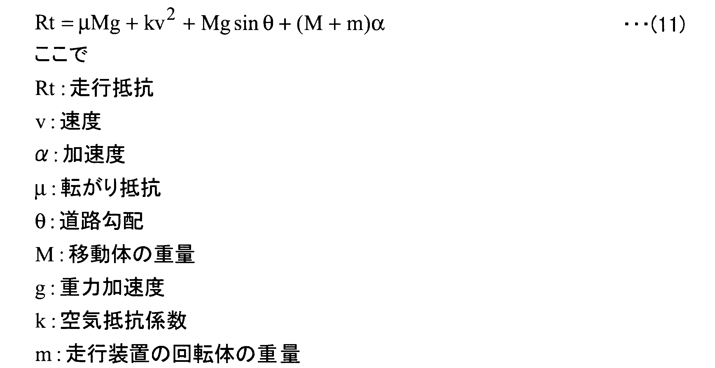
(ナビゲーション装置によるクローニング処理後の表示例)
つぎに、ナビゲーション装置によるクローニング処理後の表示例について説明する。図21は、ナビゲーション装置による到達可能地点探索処理後の表示例の一例について示す説明図である。図22-1は、ナビゲーション装置による識別情報付与処理後の表示例の一例について示す説明図である。図22-2は、ナビゲーション装置による第1識別情報変更処理後の表示例の一例について示す説明図である。また、図23は、ナビゲーション装置によるクローニング処理(膨張)後の表示例の一例について示す説明図である。図24は、ナビゲーション装置によるクローニング処理(縮小)後の表示例の一例について示す説明図である。
つぎに、ナビゲーション装置によるクローニング処理後の表示例について説明する。図21は、ナビゲーション装置による到達可能地点探索処理後の表示例の一例について示す説明図である。図22-1は、ナビゲーション装置による識別情報付与処理後の表示例の一例について示す説明図である。図22-2は、ナビゲーション装置による第1識別情報変更処理後の表示例の一例について示す説明図である。また、図23は、ナビゲーション装置によるクローニング処理(膨張)後の表示例の一例について示す説明図である。図24は、ナビゲーション装置によるクローニング処理(縮小)後の表示例の一例について示す説明図である。
図21に示すように、たとえば、ディスプレイ413には、地図データとともに、ナビゲーション装置400によって探索された複数の車両の到達可能地点が表示される。図21に示すディスプレイ413の状態は、ナビゲーション装置400によって到達可能地点探索処理がおこなわれたときの、ディスプレイに表示される情報の一例である。具体的には、図14のステップS1403の処理がおこなわれた状態である。
つぎに、ナビゲーション装置400によって地図データが複数の領域に分割され、到達可能地点に基づいて各領域に到達可能または到達不可能の識別情報が付与されることで、図22-1に示すように、ディスプレイ413には、到達可能の識別情報に基づく車両の到達可能範囲2200が表示される。この段階では、車両の到達可能範囲2200内に、到達不可能な領域からなる欠損点が生じている。
また、車両の到達可能範囲2200内には、たとえば、東京湾を横断する東京湾横断道路(東京湾アクアライン:登録商標)2210の両出入り口に相当する領域が含まれる。しかし、車両の到達可能範囲2200内には、東京湾横断道路2210上の全領域のうち、一の領域2211しか含まれていない。つぎに、ナビゲーション装置400によって第1識別情報変更処理がおこなわれることにより、図22-2に示すように東京湾横断道路上の欠損点が除去され、ディスプレイ413には、東京湾横断道路2210上の全領域2221が含まれた到達可能範囲2220が表示される。
つぎに、ナビゲーション装置400によってクローニングの膨張処理がおこなわれることにより、図23に示すように、欠損点の除去された車両の到達可能範囲2300が生成される。また、すでに、第1識別情報変更処理によって東京湾横断道路上の全領域2221が到達可能範囲2220に含まれているため、クローニングの膨張処理後においても、東京湾横断道路上の全領域2310は、車両の到達可能範囲2300となる。その後、ナビゲーション装置400によってクローニングの縮小処理がおこなわれることにより、図24に示すように、車両の到達可能範囲2400の外周は、クローニングがおこなわれる前の車両の到達可能範囲2200の外周とほぼ同様の大きさとなる。なお、図23の東京湾横断道路上の全領域2310の境界および図24の東京湾横断道路上の全領域2410の夫々の境界は、メッシュデータに依存した境界の表示となるが、ここでは分かりやすいように斜め線の境界で表示している。
そして、ナビゲーション装置400によって車両の到達可能範囲2400の輪郭2401を抽出することで、車両の到達可能範囲2400の輪郭をなめらかに表示することができる。また、クローニングによって欠損点を除去しているため、車両の到達可能範囲2400は、2次元のなめらかな面2402で表示される。また、クローニング縮小処理後においても、東京湾横断道路上の全領域2410は、車両の到達可能範囲2400またはその輪郭2401として表示される。
(到達可能範囲の拡縮の処理について)
つぎに、上記一連のエネルギー消費量算出、探索および画像処理により到達可能範囲を表示処理した後における到達可能範囲の拡縮の画像処理について説明する。上述したように、移動体に搭載されるエアコンの動作状態により移動体の到達可能範囲を変更する必要がある。
つぎに、上記一連のエネルギー消費量算出、探索および画像処理により到達可能範囲を表示処理した後における到達可能範囲の拡縮の画像処理について説明する。上述したように、移動体に搭載されるエアコンの動作状態により移動体の到達可能範囲を変更する必要がある。
図25-1は、各ノードの情報として記憶される消費電力を示す図表、図25-2は、各ノードの情報として記憶される所要時間を示す図表である。図25-1に示すように、地図情報をメッシュ状の領域に区切り、現在位置2500から各領域に到達するまでに必要なエネルギー消費量の積算(総消費電力)[kWh]が記憶される。また、図25-2に示すように、現在位置2500から各領域に到達するまでに必要な所用時間[h]についても同様に記憶される。このメッシュには、上述したように地図上で対応する緯度経度についても記憶されており、上述した膨張・縮小処理や輪郭抽出処理がおこなわれる。
(到達可能範囲の縮小の処理について)
つぎに、縮小率について説明する。拡縮率のうち、縮小率は、探索時にエアコンがOFFであり、到達可能範囲の表示後にエアコンがONに切り替わったときに用いられる。この縮小率は、すべての輪郭上の領域(画素)x,yについて、メッシュ状に記憶されている総消費電力および所要時間に基づき、エアコンがOFFからONに切り替わったときに以下の処理をおこなう。
つぎに、縮小率について説明する。拡縮率のうち、縮小率は、探索時にエアコンがOFFであり、到達可能範囲の表示後にエアコンがONに切り替わったときに用いられる。この縮小率は、すべての輪郭上の領域(画素)x,yについて、メッシュ状に記憶されている総消費電力および所要時間に基づき、エアコンがOFFからONに切り替わったときに以下の処理をおこなう。
・燃費係数k1を求める。
・画素(x,y)に到達するまでの総消費電力(Poff(x,y))[kW]と、所要時間I(x,y)[h]をメッシュの地図情報から読み出す。
・エアコンがOFFからONに切り替わったときの消費電力変化ΔP(x,y)[kW]=k1×I(x,y)により求める。
・エアコンがONの場合の総消費電力Pon=Poff+ΔP
ここで、総消費電力(on)=総消費電力(off)+所要時間×燃費係数k1となる。そして、画素(x,y)の縮小率s(x,y)=Poff(x,y)/Pon(x,y)として計算する。
・画素(x,y)に到達するまでの総消費電力(Poff(x,y))[kW]と、所要時間I(x,y)[h]をメッシュの地図情報から読み出す。
・エアコンがOFFからONに切り替わったときの消費電力変化ΔP(x,y)[kW]=k1×I(x,y)により求める。
・エアコンがONの場合の総消費電力Pon=Poff+ΔP
ここで、総消費電力(on)=総消費電力(off)+所要時間×燃費係数k1となる。そして、画素(x,y)の縮小率s(x,y)=Poff(x,y)/Pon(x,y)として計算する。
図26は、縮小率の算出の具体例を説明する図である。メッシュの地図情報2600上に到達可能範囲の輪郭2601を記載してある。燃費係数k1を0.5としたときの画素(x,y)=(5,3)の領域について、エアコンOFFの場合の総消費電力が12[kW]、所要時間が8[h]であるとする。この場合、エアコンがONになった後の総消費電力は12[kW]+8[h]×0.5[kWh]となる。
これにより、縮小率は、12/(12+8×0.5)=75%となる。
これにより、縮小率は、12/(12+8×0.5)=75%となる。
図27-1および図27-2は、到達可能範囲を縮小する際の画像処理を説明する図である。図27-1に示すように、地図情報2600上の到達可能範囲の輪郭2601の領域(画素)それぞれについて、エアコンOFFの場合の総消費電力、所要時間およびエアコンONになった後の総消費電力に基づき縮小率を算出する。
図27-2に示すように、現在位置2700から縮小率75%の画素2701aまでの距離を、縮小率に応じて変化させた後の画素2702aをエアコンONの場合の到達可能範囲とする。そして、到達可能範囲2701上の画素それぞれについて、それぞれの縮小率に応じて変化させ、エアコンONの場合の到達可能範囲を求める。これにより、それぞれの画素までの所要時間や総消費電力を鑑みた精度の高い到達可能範囲の変化を短時間で求めることができる。
図28は、到達可能範囲を縮小する手順を示すフローチャートである。探索時から表示までの全体処理を示している。はじめに、探索時には、エアコンの動作状態を検出する(ステップS2801)。OFF状態であれば(ステップS2801:OFF)、探索部103は、算出部102により算出されたエネルギー消費量に基づき、エアコンがOFFの場合の到達可能なノードを全て探索する(ステップS2802)。
つぎに、分割部104により、到達可能なノードの緯度経度点列からメッシュデータを作成する(ステップS2803)。この分割部104は、探索部103により探索された到達可能ノードの情報に基づき、各メッシュに到達するのに必要な総消費電力と、現在位置からの所要時間を保存する(ステップS2804)。つぎに、輪郭データ算出部106は、付与部105により付与された識別情報を用いてメッシュデータのなかから移動体の到達可能範囲の輪郭を抽出する(ステップS2805)。そして、メッシュデータの輪郭を構成する領域(画素)における総消費電力と所要時間を保存する(ステップS2806)。そして、表示制御部108は、到達可能範囲を表示部110に現在位置を略中心としてアメーバ状に表示し(ステップS2807)、以上の処理を終了する。
以上のように、探索時にエアコンがOFFの状態であり、ステップS2801~ステップS2807の処理をおこなって到達可能範囲を表示部110に表示した後に、エアコンがONに切り替えられた場合には(ステップS2801:ON)、以下の処理をおこなう。はじめに、算出部102は、到達可能範囲の各輪郭上のメッシュから予め保存しておいた総消費電力と所要時間に基づいてエアコンをONにした場合の消費電力変化を求める(ステップS2808)。
つぎに、算出部102は、各輪郭を構成する画素について中心からの縮小率をそれぞれ求める(ステップS2809)。そして、拡縮部107は、算出された縮小率に基づいて到達可能範囲を縮小する。縮小された到達可能範囲は、表示制御部108により表示部110に表示され(ステップS2810)、以上の処理を終了する。
ステップS2802~ステップS2807の探索時の処理時間(Tsearch)は、20sec程度かかるが、ステップS2808~ステップS2810の縮小の処理時間(Tmesh)は、1sec程度で済む。このように、探索後にエアコンがONになり、到達可能範囲を縮小する処理が必要な場合であっても、再度の探索を不要にでき画像処理により到達可能範囲を縮小するため、処理時間を短時間にできるようになる。
(到達可能範囲の拡大の処理について)
つぎに、拡大率について説明する。拡縮率のうち、拡大率は、探索時にエアコンがONであり、到達可能範囲の表示後にエアコンがOFFに切り替わったときに用いられる。この拡大率は、すべての輪郭上の領域(画素)x,yについて、メッシュ状に記憶されている総消費電力および所要時間に基づき、エアコンがONからOFFに切り替わったときに以下の処理をおこなう。
つぎに、拡大率について説明する。拡縮率のうち、拡大率は、探索時にエアコンがONであり、到達可能範囲の表示後にエアコンがOFFに切り替わったときに用いられる。この拡大率は、すべての輪郭上の領域(画素)x,yについて、メッシュ状に記憶されている総消費電力および所要時間に基づき、エアコンがONからOFFに切り替わったときに以下の処理をおこなう。
・燃費係数k1を求める。
・画素(x,y)に到達するまでの総消費電力(Pon(x,y))[kW]と、所要時間I(x,y)[h]をメッシュの地図情報から読み出す。
・エアコンがONからOFFに切り替わったときの消費電力変化ΔP(x,y)[kW]=k1×I(x,y)により求める。
・エアコンがOFFの場合の総消費電力Poff=Pon-ΔP
ここで、総消費電力(on)=総消費電力(off)+所要時間×燃費係数k1となる。そして、画素(x,y)の拡大率s(x,y)=Pon(x,y)/Poff(x,y)として計算する。
・画素(x,y)に到達するまでの総消費電力(Pon(x,y))[kW]と、所要時間I(x,y)[h]をメッシュの地図情報から読み出す。
・エアコンがONからOFFに切り替わったときの消費電力変化ΔP(x,y)[kW]=k1×I(x,y)により求める。
・エアコンがOFFの場合の総消費電力Poff=Pon-ΔP
ここで、総消費電力(on)=総消費電力(off)+所要時間×燃費係数k1となる。そして、画素(x,y)の拡大率s(x,y)=Pon(x,y)/Poff(x,y)として計算する。
図29は、拡大率の算出の具体例を説明する図である。メッシュの地図情報2600上に到達可能範囲の輪郭2601を記載してある。燃費係数k1を0.5としたときの画素(x,y)=(5,3)の領域について、エアコンONの場合の総消費電力が12[kW]、所要時間が8[h]であるとする。この場合、エアコンがOFFになった後の総消費電力は12[kW]-8[h]×0.5[kWh]となる。
これにより、拡大率は、12/(12-8×0.5)=150%となる。
これにより、拡大率は、12/(12-8×0.5)=150%となる。
図30は、到達可能範囲を拡大する手順を示すフローチャートである。探索時から表示までの全体処理を示している。はじめに、探索時には、エアコンの動作状態を検出する(ステップS3001)。ON状態であれば(ステップS3001:ON)、探索部103は、算出部102により算出されたエネルギー消費量に基づき、エアコンがONの場合の到達可能なノードを全て探索する(ステップS3002)。
つぎに、分割部104により、到達可能なノードの緯度経度点列からメッシュデータを作成する(ステップS3003)。この分割部104は、探索部103により探索された到達可能ノードの情報に基づき、各メッシュに到達するのに必要な総消費電力と、現在位置からの所要時間を保存する(ステップS3004)。つぎに、輪郭データ算出部106は、付与部105により付与された識別情報を用いてメッシュデータのなかから移動体の到達可能範囲の輪郭を抽出する(ステップS3005)。そして、メッシュデータの輪郭を構成する領域(画素)における総消費電力と所要時間を保存する(ステップS3006)。そして、表示制御部108は、到達可能範囲を表示部110に現在位置を略中心としてアメーバ状に表示し(ステップS3007)、以上の処理を終了する。
以上のように、探索時にエアコンがONの状態であり、ステップS3001~ステップS3007の処理をおこなって到達可能範囲を表示部110に表示した後に、エアコンがOFFに切り替えられた場合には(ステップS3001:OFF)、以下の処理をおこなう。はじめに、算出部102は、到達可能範囲の各輪郭上のメッシュから予め保存しておいた総消費電力と所要時間に基づいてエアコンをOFFにした場合の消費電力変化を求める(ステップS3008)。
つぎに、算出部102は、各輪郭を構成する画素について中心からの拡大率をそれぞれ求める(ステップS3009)。そして、拡縮部107は、算出された拡大率に基づいて到達可能範囲を拡大する。拡大された到達可能範囲は、表示制御部108により表示部110に表示され(ステップS3010)、以上の処理を終了する。
ステップS3002~ステップS3007の探索時の処理時間(Tsearch)は、20sec程度かかるが、ステップS3008~ステップS3010の縮小の処理時間(Tmesh)は、1sec程度で済む。このように、探索後にエアコンがOFFになり、到達可能範囲を拡大する処理が必要な場合であっても、再度の探索を不要にでき画像処理により到達可能範囲を拡大するため、処理時間を短時間にできるようになる。
(外気温度を考慮した燃費係数について)
エアコンが消費するエネルギー消費量は、必要とする温度(移動体室内)に対して外気温度が高い/あるいは低いほど増加する。一般的に、燃費係数k1は、温度依存性がある。このため、上述した燃費係数k1について、
k1(t,T(t))のパラメータを用いる。
(t:外気温度[℃]、T:設定温度[℃])。
これにより、温度変化に対応して、エアコンのエネルギー消費量をより正確に求め、到達可能範囲に反映できるようになる。
エアコンが消費するエネルギー消費量は、必要とする温度(移動体室内)に対して外気温度が高い/あるいは低いほど増加する。一般的に、燃費係数k1は、温度依存性がある。このため、上述した燃費係数k1について、
k1(t,T(t))のパラメータを用いる。
(t:外気温度[℃]、T:設定温度[℃])。
これにより、温度変化に対応して、エアコンのエネルギー消費量をより正確に求め、到達可能範囲に反映できるようになる。
図31は、温度依存性を考慮した燃費係数の設定を説明する図表である。図示の例では、変数は1個の外気温度、定数は6個(t1~t4,w1,w2)であり、
外気温度がt<t1の場合 t=t1
t>t4の場合 t=t4とする。
初期値k1=0
t<t2の場合 k1=(t2-t)×w1/(t2-t1)
t>t3の場合 k1=(t-t3)×w2/(t4-t3)
とする。
(たとえば、定数t1=0,t2=10,t3=20,t4=35[℃]、w1=4,w2=2[kWh])
外気温度がt<t1の場合 t=t1
t>t4の場合 t=t4とする。
初期値k1=0
t<t2の場合 k1=(t2-t)×w1/(t2-t1)
t>t3の場合 k1=(t-t3)×w2/(t4-t3)
とする。
(たとえば、定数t1=0,t2=10,t3=20,t4=35[℃]、w1=4,w2=2[kWh])
図32は、エアコンの冷房と暖房の違いによるエネルギー消費量に対応した燃費係数の設定を説明する図表である。上記の燃費係数k1は、より具体的には、
k1∝|t-T|×α
(α:エアコン動作の冷房/暖房の違いを表すパラメータ)
で表すことができる。
k1∝|t-T|×α
(α:エアコン動作の冷房/暖房の違いを表すパラメータ)
で表すことができる。
設定温度と外気温度との差が冷房と暖房のいずれでも同じであったとする。図示の例では、暖房時の外気温度が18[℃]、設定温度が28℃(差10[℃])であり、冷房時の外気温度が35[℃]、設定温度が25℃(差10[℃])とした。このように、冷房時と暖房時の差がいずれも同じ10[℃]であったとしても、エアコンの燃費係数k1の変化の度合いは冷房よりも暖房で動作したときの方が大きくなる。この燃費係数k1の変化の度合いは図示のように冷房と暖房動作時で異なるα(図示の例では、暖房時1.2,冷房時0.8)を用いて設定することができる。これにより、エアコンの冷房時と暖房時のエネルギー消費量の違いを含めて、より正確な燃費係数を求めることができるようになる。
(異なる設定温度ごとの到達可能範囲について)
上述した移動体の到達可能範囲は、さらに、エアコンの設定温度(すなわち、外気温度との差)に異なってくる。図33は、設定温度ごとの到達可能範囲を説明する図である。(A)に示すエアコンOFF時の到達可能範囲2701を基準として考えると、(B)に示すように、エアコンがONに切り替えられ、設定温度Ta[℃]の縮小範囲2702は、
Pon=Poff+k1(t,Ta)で表される。
また、(C)に示すように、エアコンがONに切り替えられ、設定温度Tb[℃]の縮小範囲2702は、
Pon=Poff+k1(t,Tb)で表される。
また、(D)に示すように、エアコンがONに切り替えられ、設定温度Tc[℃]の縮小範囲2702は、
Pon=Poff+k1(t,Tc)で表される。
上述した移動体の到達可能範囲は、さらに、エアコンの設定温度(すなわち、外気温度との差)に異なってくる。図33は、設定温度ごとの到達可能範囲を説明する図である。(A)に示すエアコンOFF時の到達可能範囲2701を基準として考えると、(B)に示すように、エアコンがONに切り替えられ、設定温度Ta[℃]の縮小範囲2702は、
Pon=Poff+k1(t,Ta)で表される。
また、(C)に示すように、エアコンがONに切り替えられ、設定温度Tb[℃]の縮小範囲2702は、
Pon=Poff+k1(t,Tb)で表される。
また、(D)に示すように、エアコンがONに切り替えられ、設定温度Tc[℃]の縮小範囲2702は、
Pon=Poff+k1(t,Tc)で表される。
このように、温度依存の縮小率s(t,T)=Poff/Ponにより簡単に求めることができる。
図34は、エアコンの設定温度の変更により到達可能範囲を変更する手順を示すフローチャートである。図33に対応する処理例であり、探索時にエアコンがOFFであり、その後のエアコンが所定の設定温度でONに切り替わったときに到達可能範囲を縮小する例を説明する。
はじめに、探索時には、エアコンの動作状態を検出する(ステップS3401)。OFF状態であれば(ステップS3401:OFF)、探索部103は、算出部102により算出されたエネルギー消費量に基づき、エアコンがOFFの場合の到達可能なノードを全て探索する(ステップS3402)。
つぎに、分割部104により、到達可能なノードの緯度経度点列からメッシュデータを作成する(ステップS3403)。この分割部104は、探索部103により探索された到達可能ノードの情報に基づき、各メッシュに到達するのに必要な総消費電力と、現在位置からの所要時間を保存する。つぎに、輪郭データ算出部106は、付与部105により付与された識別情報を用いてメッシュデータのなかから移動体の到達可能範囲の輪郭を抽出する(ステップS3404)。そして、メッシュデータの輪郭を構成する領域(画素)における総消費電力と所要時間を保存する。この後、表示制御部108は、到達可能範囲を表示部110に現在位置を略中心としてアメーバ状に表示し(ステップS3405)、以上の処理を終了する。
以上のように、探索時にエアコンがOFFの状態であり、ステップS3401~ステップS3405の処理をおこなって到達可能範囲を表示部110に表示した後に、エアコンがONに切り替えられた場合には(ステップS3401:ON)、以下の処理をおこなう。はじめに、取得部101は、エアコンの設定温度を取得し(ステップS3406)、以下、エアコンの設定温度A~C別の処理をおこなう。
設定温度Aの場合には、算出部102は、到達可能範囲の各輪郭上のメッシュから予め保存しておいた総消費電力と所要時間、外気温度とエアコンの設定温度Aに基づいてエアコンをONにした場合の消費電力変化を求める(ステップS3407)。
つぎに、算出部102は、各輪郭を構成する画素について中心からの縮小率をそれぞれ求める(ステップS3408)。そして、拡縮部107は、算出された縮小率に基づいて到達可能範囲を縮小する。縮小された到達可能範囲は、図33の(B)に示すように、表示制御部108により表示部110に表示され(ステップS3409)、以上の処理を終了する。
設定温度Bの場合には、算出部102は、到達可能範囲の各輪郭上のメッシュから予め保存しておいた総消費電力と所要時間、外気温度とエアコンの設定温度Bに基づいてエアコンをONにした場合の消費電力変化を求める(ステップS3410)。
つぎに、算出部102は、各輪郭を構成する画素について中心からの縮小率をそれぞれ求める(ステップS3411)。そして、拡縮部107は、算出された縮小率に基づいて到達可能範囲を縮小する。縮小された到達可能範囲は、図33の(C)に示すように、表示制御部108により表示部110に表示され(ステップS3412)、以上の処理を終了する。
設定温度Cの場合には、算出部102は、到達可能範囲の各輪郭上のメッシュから予め保存しておいた総消費電力と所要時間、外気温度とエアコンの設定温度Cに基づいてエアコンをONにした場合の消費電力変化を求める(ステップS3413)。
つぎに、算出部102は、各輪郭を構成する画素について中心からの縮小率をそれぞれ求める(ステップS3414)。そして、拡縮部107は、算出された縮小率に基づいて到達可能範囲を縮小する。縮小された到達可能範囲は、図33の(D)に示すように、表示制御部108により表示部110に表示され(ステップS3415)、以上の処理を終了する。
ステップS3402~ステップS3405の探索時の処理時間(Tsearch)は、20sec程度かかるが、エアコンがONに切り替えられた後の設定温度A~C(ステップS3407~ステップS3409、ステップS3410~ステップS3412、ステップS3413~ステップS3415)別の縮小の処理時間(Tmesh)は、1sec程度で済む。このように、探索後にエアコンが所定の設定温度でONになり、到達可能範囲を縮小する処理が必要な場合であっても、再度の探索を不要にでき画像処理により到達可能範囲を縮小するため、処理時間を短時間にできるようになる。上記の処理例に限らず、探索時のエアコンがONであり、探索後にエアコンがOFFに切り替わったときにおいても、必要な到達可能範囲の拡大処理を同様に簡単におこなうことができる。
以上説明したように、ナビゲーション装置400によれば、地図情報を複数の領域に分割して各領域ごとに移動体が到達可能か否かを探索し、各領域にそれぞれ移動体が到達可能または到達不可能であることを識別する到達可能または到達不可能の識別情報を付与する。そして、ナビゲーション装置400は、到達可能の識別情報が付与された領域に基づいて、移動体の到達可能範囲を生成する。このため、ナビゲーション装置400は、海や湖、山脈など移動体の走行不可能な領域を除いた状態で移動体の到達可能範囲を生成することができる。したがって、画像処理装置100は、移動体の到達可能範囲を正確に表示することができる。
また、ナビゲーション装置400は、地図情報を分割した複数の領域を画像データに変換し、当該複数の領域にそれぞれ到達可能または到達不可能の識別情報を付与した後、クローニングの膨張処理をおこなう。このため、ナビゲーション装置400は、移動体の到達可能範囲内の欠損点を除去することができる。
また、ナビゲーション装置400は、地図情報を分割した複数の領域を画像データに変換し、当該複数の領域にそれぞれ到達可能または到達不可能の識別情報を付与した後、オープニングの縮小処理をおこなう。このため、ナビゲーション装置400は、移動体の到達可能範囲の孤立点を除去することができる。
このように、ナビゲーション装置400は、移動体の到達可能範囲の欠損点や孤立点を除去することができるので、移動体の走行可能範囲を2次元のなめらかな面でかつ見やすく表示することができる。また、ナビゲーション装置400は、地図情報を複数の領域に分割して生成したメッシュデータの輪郭を抽出する。このため、ナビゲーション装置400は、移動体の到達可能範囲の輪郭をなめらかに表示することができる。
また、ナビゲーション装置400は、移動体の到達可能地点を探索する道路を絞り込んで、移動体の到達可能地点を探索する。このため、ナビゲーション装置400は、移動体の到達可能地点を探索する際の処理量を低減することができる。移動体の到達可能地点を探索する道路を絞り込むことで、探索可能な到達可能地点が少なくなったとしても、上述したようにクローニングの膨張処理がおこなわれることにより、移動体の到達可能範囲内に生じる欠損点を除去することができる。したがって、ナビゲーション装置400は、移動体の到達可能範囲を検出するための処理量を低減することができる。また、ナビゲーション装置400は、移動体の走行可能範囲を2次元のなめらかな面で見やすく表示することができる。
そして、探索による到達可能範囲の表示後に、移動体に備えられた装備品により消費されるエネルギー、特にエアコン等の消費電力が大きい装備品の動作の切り替え(ON/OFF)があった場合でも、到達可能範囲を簡単に変更することができるようになる。そして、探索時にメッシュの地図情報の各領域には、緯度経度とともに、移動体の現在位置からのエネルギー消費量と所要時間を記憶し、エアコンのON/OFFの切り替えに基づいて到達可能範囲の輪郭の領域のエネルギー消費量と所要時間を読み出し、画像処理により到達可能範囲を拡大または縮小するようにしている。これにより、探索後のエアコンの動作状態が切り替わっても、再探索をおこなう必要がなく、簡単な画像処理で短時間に変更後の到達可能範囲を表示できるようになる。
また、外気温度とエアコンの設定温度に対応して画像処理により到達可能範囲を変更することができ、エアコンが消費するエネルギーに対応して到達可能範囲をより細かく変更できるようになる。
(実施の形態2)
図35は、実施の形態2にかかる画像処理システムの機能的構成の一例を示すブロック図である。実施の形態2にかかる画像処理システム3500の機能的構成について説明する。実施の形態2にかかる画像処理システム3500は、サーバ3510、端末3520によって構成される。実施の形態2にかかる画像処理システム3500は、実施の形態1の画像処理装置100の機能をサーバ3510および端末3520に備える。
図35は、実施の形態2にかかる画像処理システムの機能的構成の一例を示すブロック図である。実施の形態2にかかる画像処理システム3500の機能的構成について説明する。実施の形態2にかかる画像処理システム3500は、サーバ3510、端末3520によって構成される。実施の形態2にかかる画像処理システム3500は、実施の形態1の画像処理装置100の機能をサーバ3510および端末3520に備える。
サーバ3510は、移動体に搭載された端末3520によって表示部110に表示させる情報を生成する。具体的には、サーバ3510は、移動体の到達可能範囲に関する情報を検出し端末3520に送信する。端末3520は、移動体に搭載されても構わないし、携帯端末として移動体のなかで利用されても構わないし、携帯端末として移動体の外で利用されても構わない。そして、端末3520は、サーバ3510から移動体の到達可能範囲に関する情報を受信する。
図35において、サーバ3510は、算出部102、探索部103、分割部104、付与部105、輪郭データ算出部106、拡縮部107、サーバ受信部3511、サーバ送信部3512によって構成される。端末3520は、取得部101、表示制御部108、端末受信部3521、端末送信部3522によって構成される。なお、図35に示す画像処理システム3500においては、図1に示した画像処理装置100と同一の構成部に同一の符号を付し、説明を省略する。
サーバ3510において、サーバ受信部3511は、端末3520から送信された情報を受信する。具体的には、たとえば、サーバ受信部3511は、公衆回線網や携帯電話網、DSRC、LAN、WANなどの通信網に無線を介して接続された端末3520からの移動体に関する情報を受信する。移動体に関する情報とは、移動体の現在地点に関する情報、および、移動体の現在地点において移動体が保有するエネルギー量である初期保有エネルギー量に関する情報である。サーバ受信部3511によって受信された情報は、算出部102で参照される情報である。
サーバ送信部3512は、付与部105によって移動体が到達可能であることを識別する到達可能の識別情報が付与された地図情報が分割されてなる複数の領域を移動体の到達可能範囲として、端末3520に送信する。具体的には、たとえば、サーバ送信部3512は、公衆回線網や携帯電話網、DSRC、LAN、WANなどの通信網に無線を介して接続された端末3520に情報を送信する。
端末3520は、たとえば、携帯端末の情報通信網や自装置に備えられた通信部(不図示)を介して通信可能な状態で、サーバ3510と接続されている。
端末3520において、端末受信部3521は、サーバ3510からの情報を受信する。具体的には、端末受信部3521は、複数の領域に分割され、かつ当該領域のそれぞれに、移動体の到達可能地点に基づいて到達可能または到達不可能の識別情報が付与された地図情報を受信する。より具体的には、たとえば、端末受信部3521は、公衆回線網や携帯電話網、DSRC、LAN、WANなどの通信網に無線を介して接続されたサーバ3510から情報を受信する。
端末送信部3522は、取得部101に取得された移動体に関する情報をサーバ3510に送信する。具体的には、たとえば、端末送信部3522は、公衆回線網や携帯電話網、DSRC、LAN、WANなどの通信網に無線を介して接続されたサーバ3510に移動体に関する情報を送信する。
つぎに、実施の形態2にかかる画像処理システム3500による画像処理について説明する。画像処理システム3500による画像処理は、実施の形態1にかかる画像処理装置100とほぼ同一であるため、図2のフローチャートを利用して実施の形態1との差異について説明する。
画像処理システム3500による画像処理は、実施の形態1にかかる画像処理装置100による画像処理のうち、推定エネルギー消費量算出処理、到達可能地点探索処理、識別情報付与処理、輪郭データ算出,拡縮処理をサーバ3510がおこなう。具体的には、図2のフローチャートにおいて、端末3520は、ステップS201の処理をおこない、ステップS201で取得した情報をサーバ3510に送信する。
つぎに、サーバ3510は、端末3520からの情報を受信する。つぎに、サーバ3510は、端末3520から受信した情報に基づいてステップS202~S207の処理をおこない、ステップS207で取得した情報を端末3520に送信する。つぎに、端末3520は、サーバ3510からの情報を受信する。そして、端末3520は、サーバ3510から受信した情報に基づいてステップS208をおこなう。
そして、端末3520では、ステップS209の処理を判断し、エアコンの切り替えがなければ本フローチャートによる処理を終了し、エアコンの切り替えがあればステップS210の処理をおこない、本フローチャートによる処理を終了する。
以上説明したように、実施の形態2にかかる画像処理システム3500および画像処理方法は、実施の形態1にかかる画像処理装置100および画像処理方法と同様の効果を得ることができる。
(実施の形態3)
図36は、実施の形態3にかかる画像処理システムの機能的構成の一例を示すブロック図である。実施の形態3にかかる画像処理システム3600の機能的構成について説明する。実施の形態3にかかる画像処理システム3600は、第1サーバ3610、第2サーバ3620、第3サーバ3630、端末3640によって構成される。画像処理システム3600は、実施の形態1の画像処理装置100の算出部102の機能を第1サーバ3610が備え、実施の形態1の画像処理装置100の探索部103の機能を第2サーバ3620が備え、実施の形態1の画像処理装置100の分割部104、付与部105、輪郭データ算出部106、拡縮部107の機能を第3サーバ3630が備え、実施の形態1の画像処理装置100の取得部101および表示制御部108の機能を端末3640が備える。
図36は、実施の形態3にかかる画像処理システムの機能的構成の一例を示すブロック図である。実施の形態3にかかる画像処理システム3600の機能的構成について説明する。実施の形態3にかかる画像処理システム3600は、第1サーバ3610、第2サーバ3620、第3サーバ3630、端末3640によって構成される。画像処理システム3600は、実施の形態1の画像処理装置100の算出部102の機能を第1サーバ3610が備え、実施の形態1の画像処理装置100の探索部103の機能を第2サーバ3620が備え、実施の形態1の画像処理装置100の分割部104、付与部105、輪郭データ算出部106、拡縮部107の機能を第3サーバ3630が備え、実施の形態1の画像処理装置100の取得部101および表示制御部108の機能を端末3640が備える。
図36において、端末3640は、実施の形態2の端末3520と同様の構成を有する。具体的には、端末3640は、取得部101、表示制御部108、端末受信部3641、端末送信部3642によって構成される。端末受信部3641は、実施の形態2の端末受信部3521と同様の構成を有する。端末送信部3642は、実施の形態2の端末送信部3522と同様の構成を有する。第1サーバ3610は、算出部102、第1サーバ受信部3611、第1サーバ送信部3612、によって構成される。
第2サーバ3620は、探索部103、第2サーバ受信部3621、第2サーバ送信部3622、によって構成される。第3サーバ3630は、分割部104、付与部105、輪郭データ算出部106、拡縮部107、第3サーバ受信部3631、第3サーバ送信部3632、によって構成される。図36に示す画像処理システム3600においては、図1に示した画像処理装置100および図35に示した画像処理システム3500と同一の構成部に同一の符号を付し、説明を省略する。
第1サーバ3610において、第1サーバ受信部3611は、端末3640から送信された情報を受信する。具体的には、たとえば、第1サーバ受信部3611は、公衆回線網や携帯電話網、DSRC、LAN、WANなどの通信網に無線を介して接続された端末3640の端末送信部3642からの情報を受信する。第1サーバ受信部3611によって受信された情報は、算出部102で参照される情報である。
第1サーバ送信部3612は、算出部102によって算出された情報を第2サーバ受信部3621に送信する。具体的には、第1サーバ送信部3612は、公衆回線網や携帯電話網、DSRC、LAN、WANなどの通信網に無線を介して接続された第2サーバ受信部3621に情報を送信してもよいし、有線で接続された第2サーバ受信部3621に情報を送信してもよい。
第2サーバ3620において、第2サーバ受信部3621は、端末送信部3642および第1サーバ送信部3612によって送信された情報を受信する。具体的には、たとえば、第2サーバ受信部3621は、公衆回線網や携帯電話網、DSRC、LAN、WANなどの通信網に無線を介して接続された第1サーバ送信部3612および端末送信部3642からの情報を受信する。第2サーバ受信部3621は、有線で接続された第1サーバ送信部3612からの情報を受信してもよい。第2サーバ受信部3621によって受信された情報は、探索部103で参照される情報である。
第2サーバ送信部3622は、探索部103によって探索された情報を第3サーバ受信部3631に送信する。具体的には、たとえば、第2サーバ送信部3622は、公衆回線網や携帯電話網、DSRC、LAN、WANなどの通信網に無線を介して接続された第3サーバ受信部3631に情報を送信してもよいし、有線で接続された第3サーバ受信部3631に情報を送信してもよい。
第3サーバ3630において、第3サーバ受信部3631は、端末送信部3642および第2サーバ送信部3622によって送信された情報を受信する。具体的には、たとえば、第3サーバ受信部3631は、公衆回線網や携帯電話網、DSRC、LAN、WANなどの通信網に無線を介して接続された第2サーバ送信部3622および端末送信部3642からの情報を受信してもよい。第3サーバ受信部3631は、有線で接続された第2サーバ送信部3622からの情報を受信してもよい。第2サーバ受信部3621によって受信された情報は、分割部104で参照される情報である。
第3サーバ送信部3632は、付与部105によって生成された情報を端末受信部3641に送信する。具体的には、たとえば、第3サーバ送信部3632は、公衆回線網や携帯電話網、DSRC、LAN、WANなどの通信網に無線を介して接続された端末受信部3641に情報を送信する。
つぎに、実施の形態3にかかる画像処理システム3600による画像処理について説明する。画像処理システム3600による画像処理は、実施の形態1にかかる画像処理装置100とほぼ同一であるため、図2のフローチャートを利用して実施の形態1との差異について説明する。
画像処理システム3600による画像処理は、実施の形態1にかかる画像処理装置100による画像処理のうち、推定エネルギー消費量算出処理を第1サーバ3610がおこない、到達可能地点探索処理を第2サーバ3620がおこない、識別情報付与処理を第3サーバ3630がおこなう。図2のフローチャートにおいて、端末3640は、ステップS201の処理をおこない、ステップS201で取得した情報を第1サーバ3610に送信する。
つぎに、第1サーバ3610は、端末3640からの情報を受信する。つぎに、第1サーバ3610は、端末3640から受信した情報に基づいてステップS202,S203の処理をおこない、ステップS203で算出した情報を第2サーバ3620に送信する。つぎに、第2サーバ3620は、第1サーバ3610からの情報を受信する。つぎに、第2サーバ3620は、第1サーバ3610から受信した情報に基づいてステップS204の処理をおこない、ステップS204で探索した情報を第3サーバ3630に送信する。
つぎに、第3サーバ3630は、第2サーバ3620からの情報を受信する。つぎに、第3サーバ3630は、第2サーバ3620からの情報に基づいてステップS206~ステップS207の処理をおこない、ステップS208で生成した情報を端末3640に送信する。つぎに、端末3640は、第3サーバ3630からの情報を受信する。そして、端末3640は、第3サーバ3630から受信した情報に基づいてステップS208をおこなう。
そして、端末3640では、ステップS209の処理を判断し、エアコンの切り替えがなければ本フローチャートによる処理を終了し、エアコンの切り替えがあればステップS210の処理をおこない、本フローチャートによる処理を終了する。
以上説明したように、実施の形態3にかかる画像処理システム3600および画像処理方法は、実施の形態1にかかる画像処理装置100および画像処理方法と同様の効果を得ることができる。
以下に、本発明の実施例2について説明する。図37は、実施例2にかかる画像処理装置のシステム構成の一例を示す説明図である。本実施例2では、車両に搭載されたナビゲーション装置3710を端末3520とし、サーバ3720をサーバ3510とする画像処理システム3700において、本発明を適用した場合の一例について説明する。画像処理システム3700は、車両3730に搭載されたナビゲーション装置3710、サーバ3720、ネットワーク3740によって構成される。
ナビゲーション装置3710は、車両3730に搭載されている。ナビゲーション装置3710は、サーバ3720に車両の現在地点の情報および初期保有エネルギー量に関する情報を送信する。また、ナビゲーション装置3710は、サーバ3720から受信した情報をディスプレイに表示してユーザに報知する。サーバ3720は、ナビゲーション装置3710から車両の現在地点の情報および初期保有エネルギー量に関する情報を受信する。サーバ3720は、受信した車両情報に基づいて、車両3730の到達可能範囲に関する情報を生成する。
サーバ3720およびナビゲーション装置3710のハードウェア構成は、実施例1のナビゲーション装置400のハードウェア構成と同一である。また、ナビゲーション装置3710は、車両情報をサーバ3720に送信する機能と、サーバ3720からの情報を受信してユーザに報知する機能に該当するハードウェア構成のみを備えていればよい。
また、画像処理システム3700は、車両に搭載されたナビゲーション装置3710を実施の形態3の端末3640とし、サーバ3720の機能構成を実施の形態3の第1~3サーバ3610~3630に分散させた構成としてもよい。
なお、本実施の形態で説明した画像処理方法は、予め用意されたプログラムをパーソナル・コンピュータやワークステーションなどのコンピュータで実行することにより実現することができる。このプログラムは、ハードディスク、フレキシブルディスク、CD-ROM、MO、DVDなどのコンピュータで読み取り可能な記録媒体に記録され、コンピュータによって記録媒体から読み出されることによって実行される。またこのプログラムは、インターネットなどのネットワークを介して配布することが可能な伝送媒体であってもよい。
100 画像処理装置
101 取得部
102 算出部
103 探索部
104 分割部
105 付与部
106 輪郭データ算出部
107 拡縮部
108 表示制御部
110 表示部
101 取得部
102 算出部
103 探索部
104 分割部
105 付与部
106 輪郭データ算出部
107 拡縮部
108 表示制御部
110 表示部
Claims (7)
- 移動体の到達可能範囲に関する情報を処理する画像処理装置であって、
前記移動体の現在位置に関する情報、前記移動体が保有するエネルギー量に関する情報、および、前記移動体が所定区間を走行する際に消費するエネルギー量を示す推定エネルギー消費量に基づき、前記移動体の複数の到達可能な領域を含む到達可能範囲を算出する到達可能範囲算出手段と、
前記移動体に備えられた装備品の動作状態が変化したとき、当該装備品が消費するエネルギー量の変化分に対応した拡縮率を算出し、当該拡縮率に基づき前記到達可能範囲の輪郭を拡大または縮小させる拡縮手段と、
前記拡縮手段により拡大または縮小された前記到達可能範囲の輪郭を表示手段に表示させる表示制御手段と、
を備えることを特徴とする画像処理装置。 - 前記到達可能範囲算出手段は、前記移動体の複数の到達可能な領域ごとに現在位置から当該領域までの推定エネルギー消費量の総和および所要時間を求めて記憶する記憶手段を備えることを特徴とする請求項1に記載の画像処理装置。
- 前記拡縮手段は、前記到達可能範囲の輪郭に対応する各領域へ記憶された推定エネルギー消費量の総和および所要時間を前記記憶手段より抽出し、抽出された前記推定エネルギー消費量の総和および所要時間に基づき、前記到達可能範囲の輪郭を拡大または縮小させることを特徴とする請求項2に記載の画像処理装置。
- 前記装備品はエアコンであり、
前記拡縮手段は、前記エアコンの電源のONとOFFの切り替え、外気温度および設定温度に基づき消費するエネルギー量の推定される変化分に基づき、前記到達可能範囲の輪郭を拡大または縮小させることを特徴とする請求項1に記載の画像処理装置。 - 移動体の到達可能範囲に関する情報を処理する画像処理管理装置であって、
前記移動体の現在位置に関する情報、前記移動体が保有するエネルギー量に関する情報、および、前記移動体に備えられた装備品の動作状態の変化に関する情報を受信する受信手段と、
前記移動体の現在位置に関する情報、前記移動体が保有するエネルギー量に関する情報、および、前記移動体が所定区間を走行する際に消費するエネルギー量を示す推定エネルギー消費量に基づき、前記移動体の複数の到達可能な領域を含む到達可能範囲を算出する到達可能範囲算出手段と、
前記移動体に備えられた装備品の動作状態が変化したとき、当該装備品が消費するエネルギー量の変化分に対応した拡縮率を算出し、当該拡縮率に基づき前記到達可能範囲の輪郭を拡大または縮小させる拡縮手段と、
前記拡縮手段により拡大または縮小された前記到達可能範囲の輪郭を送信する送信手段と、
を備えることを特徴とする画像処理管理装置。 - 移動体の到達可能範囲に関する情報を処理する端末であって、
前記移動体の現在位置に関する情報、前記移動体が保有するエネルギー量に関する情報、および、前記移動体に備えられた装備品の動作状態の変化に関する情報を送信する送信手段と、
前記送信手段により送信された前記移動体の現在位置に関する情報、および、前記移動体が保有するエネルギー量に関する情報、および、前記移動体が所定区間を走行する際に消費するエネルギー量を示す推定エネルギー消費量に基づき、前記移動体の複数の到達可能な領域を含む到達可能範囲を算出し、前記移動体に備えられた装備品の動作状態が変化したとき、当該装備品が消費するエネルギー量の変化分に対応した拡縮率を算出し、当該拡縮率に基づき拡大または縮小された前記到達可能範囲の輪郭を受信する受信手段と、
前記受信手段により受信された拡大または縮小された前記到達可能範囲の輪郭を表示手段に表示させる表示制御手段と、
を備えることを特徴とする端末。 - 移動体の到達可能範囲に関する情報を処理する画像処理装置の画像処理方法であって、
前記移動体の現在位置に関する情報、前記移動体が保有するエネルギー量に関する情報、および、前記移動体が所定区間を走行する際に消費するエネルギー量を示す推定エネルギー消費量に基づき、前記移動体の複数の到達可能な領域を含む到達可能範囲を算出する到達可能範囲算出工程と、
前記移動体に備えられた装備品の動作状態が変化したとき、当該装備品が消費するエネルギー量の変化分に対応した拡縮率を算出し、当該拡縮率に基づき前記到達可能範囲の輪郭を拡大または縮小させる拡縮工程と、
前記拡縮工程により拡大または縮小された前記到達可能範囲の輪郭を表示手段に表示させる表示制御工程と、
を含むことを特徴とする画像処理方法。
Priority Applications (1)
| Application Number | Priority Date | Filing Date | Title |
|---|---|---|---|
| PCT/JP2012/050639 WO2013105271A1 (ja) | 2012-01-13 | 2012-01-13 | 画像処理装置、画像処理管理装置、端末および画像処理方法 |
Applications Claiming Priority (1)
| Application Number | Priority Date | Filing Date | Title |
|---|---|---|---|
| PCT/JP2012/050639 WO2013105271A1 (ja) | 2012-01-13 | 2012-01-13 | 画像処理装置、画像処理管理装置、端末および画像処理方法 |
Publications (1)
| Publication Number | Publication Date |
|---|---|
| WO2013105271A1 true WO2013105271A1 (ja) | 2013-07-18 |
Family
ID=48781241
Family Applications (1)
| Application Number | Title | Priority Date | Filing Date |
|---|---|---|---|
| PCT/JP2012/050639 Ceased WO2013105271A1 (ja) | 2012-01-13 | 2012-01-13 | 画像処理装置、画像処理管理装置、端末および画像処理方法 |
Country Status (1)
| Country | Link |
|---|---|
| WO (1) | WO2013105271A1 (ja) |
Cited By (2)
| Publication number | Priority date | Publication date | Assignee | Title |
|---|---|---|---|---|
| WO2021151278A1 (zh) * | 2020-05-28 | 2021-08-05 | 平安科技(深圳)有限公司 | 基于人工智能的车辆定损方法、装置、电子设备及介质 |
| CN116010722A (zh) * | 2022-12-26 | 2023-04-25 | 北京大学 | 一种基于网格时空知识图谱的动态多目标时空问题的查询方法 |
Citations (3)
| Publication number | Priority date | Publication date | Assignee | Title |
|---|---|---|---|---|
| JP2010139386A (ja) * | 2008-12-11 | 2010-06-24 | Aisin Aw Co Ltd | 車載用表示制御装置、車載用表示制御方法および車載用表示制御プログラム |
| JP2010226795A (ja) * | 2009-03-19 | 2010-10-07 | Fuji Heavy Ind Ltd | 電気自動車の制御装置 |
| JP2011217509A (ja) * | 2010-03-31 | 2011-10-27 | Nissan Motor Co Ltd | 電気自動車用表示装置及び表示方法 |
-
2012
- 2012-01-13 WO PCT/JP2012/050639 patent/WO2013105271A1/ja not_active Ceased
Patent Citations (3)
| Publication number | Priority date | Publication date | Assignee | Title |
|---|---|---|---|---|
| JP2010139386A (ja) * | 2008-12-11 | 2010-06-24 | Aisin Aw Co Ltd | 車載用表示制御装置、車載用表示制御方法および車載用表示制御プログラム |
| JP2010226795A (ja) * | 2009-03-19 | 2010-10-07 | Fuji Heavy Ind Ltd | 電気自動車の制御装置 |
| JP2011217509A (ja) * | 2010-03-31 | 2011-10-27 | Nissan Motor Co Ltd | 電気自動車用表示装置及び表示方法 |
Cited By (3)
| Publication number | Priority date | Publication date | Assignee | Title |
|---|---|---|---|---|
| WO2021151278A1 (zh) * | 2020-05-28 | 2021-08-05 | 平安科技(深圳)有限公司 | 基于人工智能的车辆定损方法、装置、电子设备及介质 |
| CN116010722A (zh) * | 2022-12-26 | 2023-04-25 | 北京大学 | 一种基于网格时空知识图谱的动态多目标时空问题的查询方法 |
| CN116010722B (zh) * | 2022-12-26 | 2025-11-21 | 北京大学 | 一种基于网格时空知识图谱的动态多目标时空问题的查询方法 |
Similar Documents
| Publication | Publication Date | Title |
|---|---|---|
| CN103748432B (zh) | 图像处理装置、图像处理管理装置、终端、处理装置以及图像处理方法 | |
| JP2025129219A (ja) | 到達可能範囲算出装置、到達可能範囲算出方法および到達可能範囲算出プログラム | |
| WO2013105271A1 (ja) | 画像処理装置、画像処理管理装置、端末および画像処理方法 | |
| CN112985447B (zh) | 信息处理装置、信息处理系统、存储介质及信息处理方法 | |
| JP6058756B2 (ja) | 画像処理装置および画像処理方法 | |
| JP6047651B2 (ja) | 画像処理装置および画像処理方法 | |
| WO2013125019A1 (ja) | 画像処理装置および画像処理方法 | |
| JP5819445B2 (ja) | 画像処理装置、画像処理管理装置、端末および画像処理方法 | |
| CN104321621A (zh) | 图像处理装置和图像处理方法 | |
| JP2016006695A (ja) | 補充設備検索装置、補充設備検索方法および補充設備検索プログラム | |
| JP5619288B2 (ja) | 画像処理装置、画像処理管理装置、端末、処理装置および画像処理方法 | |
| JP5816705B2 (ja) | 画像処理装置、画像処理管理装置、端末、画像処理方法およびデータ構造 | |
| WO2014045432A1 (ja) | 画像処理装置および画像処理方法 | |
| JP2019212314A (ja) | 到達可能範囲算出装置、到達可能範囲算出方法および到達可能範囲算出プログラム | |
| WO2013114579A1 (ja) | 画像処理装置、画像処理方法および画像処理プログラム | |
| JPWO2014016948A1 (ja) | 画像処理装置、画像処理方法および画像処理プログラム | |
| JPWO2013125019A1 (ja) | 画像処理装置および画像処理方法 | |
| JP2019049569A (ja) | 画像処理装置、画像処理方法および画像処理プログラム | |
| WO2014080506A1 (ja) | 表示制御装置、表示制御方法、表示制御プログラム、表示制御システム、表示制御サーバおよび端末 | |
| JP2017227652A (ja) | 画像処理装置、画像処理方法および画像処理プログラム | |
| JP2018032414A (ja) | 到達可能範囲算出装置、到達可能範囲算出方法および到達可能範囲算出プログラム | |
| JP2017187498A (ja) | 画像処理装置、画像処理方法および画像処理プログラム | |
| JP2025065281A (ja) | 画像処理装置、画像処理方法および画像処理プログラム | |
| WO2014038026A1 (ja) | 画像処理装置および画像処理方法 | |
| WO2014068685A1 (ja) | 表示制御装置、サーバ装置、表示制御方法、表示制御プログラムおよび記録媒体 |
Legal Events
| Date | Code | Title | Description |
|---|---|---|---|
| 121 | Ep: the epo has been informed by wipo that ep was designated in this application |
Ref document number: 12864695 Country of ref document: EP Kind code of ref document: A1 |
|
| NENP | Non-entry into the national phase |
Ref country code: DE |
|
| 122 | Ep: pct application non-entry in european phase |
Ref document number: 12864695 Country of ref document: EP Kind code of ref document: A1 |
|
| NENP | Non-entry into the national phase |
Ref country code: JP |