WO2013104828A1 - A vibration tolerant accelaration sensor structure - Google Patents
A vibration tolerant accelaration sensor structure Download PDFInfo
- Publication number
- WO2013104828A1 WO2013104828A1 PCT/FI2013/050025 FI2013050025W WO2013104828A1 WO 2013104828 A1 WO2013104828 A1 WO 2013104828A1 FI 2013050025 W FI2013050025 W FI 2013050025W WO 2013104828 A1 WO2013104828 A1 WO 2013104828A1
- Authority
- WO
- WIPO (PCT)
- Prior art keywords
- mems structure
- spring
- side arm
- seismic mass
- anchor
- Prior art date
Links
Classifications
-
- G—PHYSICS
- G01—MEASURING; TESTING
- G01P—MEASURING LINEAR OR ANGULAR SPEED, ACCELERATION, DECELERATION, OR SHOCK; INDICATING PRESENCE, ABSENCE, OR DIRECTION, OF MOVEMENT
- G01P15/00—Measuring acceleration; Measuring deceleration; Measuring shock, i.e. sudden change of acceleration
- G01P15/02—Measuring acceleration; Measuring deceleration; Measuring shock, i.e. sudden change of acceleration by making use of inertia forces using solid seismic masses
- G01P15/08—Measuring acceleration; Measuring deceleration; Measuring shock, i.e. sudden change of acceleration by making use of inertia forces using solid seismic masses with conversion into electric or magnetic values
- G01P15/125—Measuring acceleration; Measuring deceleration; Measuring shock, i.e. sudden change of acceleration by making use of inertia forces using solid seismic masses with conversion into electric or magnetic values by capacitive pick-up
-
- G—PHYSICS
- G01—MEASURING; TESTING
- G01P—MEASURING LINEAR OR ANGULAR SPEED, ACCELERATION, DECELERATION, OR SHOCK; INDICATING PRESENCE, ABSENCE, OR DIRECTION, OF MOVEMENT
- G01P15/00—Measuring acceleration; Measuring deceleration; Measuring shock, i.e. sudden change of acceleration
- G01P15/02—Measuring acceleration; Measuring deceleration; Measuring shock, i.e. sudden change of acceleration by making use of inertia forces using solid seismic masses
- G01P15/08—Measuring acceleration; Measuring deceleration; Measuring shock, i.e. sudden change of acceleration by making use of inertia forces using solid seismic masses with conversion into electric or magnetic values
- G01P2015/0805—Measuring acceleration; Measuring deceleration; Measuring shock, i.e. sudden change of acceleration by making use of inertia forces using solid seismic masses with conversion into electric or magnetic values being provided with a particular type of spring-mass-system for defining the displacement of a seismic mass due to an external acceleration
- G01P2015/0822—Measuring acceleration; Measuring deceleration; Measuring shock, i.e. sudden change of acceleration by making use of inertia forces using solid seismic masses with conversion into electric or magnetic values being provided with a particular type of spring-mass-system for defining the displacement of a seismic mass due to an external acceleration for defining out-of-plane movement of the mass
- G01P2015/0825—Measuring acceleration; Measuring deceleration; Measuring shock, i.e. sudden change of acceleration by making use of inertia forces using solid seismic masses with conversion into electric or magnetic values being provided with a particular type of spring-mass-system for defining the displacement of a seismic mass due to an external acceleration for defining out-of-plane movement of the mass for one single degree of freedom of movement of the mass
- G01P2015/0831—Measuring acceleration; Measuring deceleration; Measuring shock, i.e. sudden change of acceleration by making use of inertia forces using solid seismic masses with conversion into electric or magnetic values being provided with a particular type of spring-mass-system for defining the displacement of a seismic mass due to an external acceleration for defining out-of-plane movement of the mass for one single degree of freedom of movement of the mass the mass being of the paddle type having the pivot axis between the longitudinal ends of the mass, e.g. see-saw configuration
Definitions
- the invention in general relates to MEMS (Micro-Electro-Mechanical-Systems) technologies, but more specifically to an improved MEMS structure as defined in the preamble of the independent claim.
- the invention relates also to an accelerator sensor, an acceleration sensor matrix, a device and a system including the improved MEMS structure.
- Sensing acceleration of a body to provide a signal that depends on the kinetic state of said body under the influence of the acting forces is a widely applied way to detect movement and orientations of the body.
- various sensors can be used, but MEMS structures are suitable for many applications because of their small size.
- MEMS structures are suitable for many applications because of their small size.
- the increasing demand has made it possible to develop better and better structures for purposes encountered in many fields, for example such that relate to vehicles, domestic electronics, clothes, shoes, to mention a few applied fields in which patent classes may comprise MEMS related acceleration sensors.
- MEMS structures to measure acceleration or the related forces also need to appropriately control error signals.
- error signals may be caused by sudden transient forces, but also by periodic forces that are superposed from various components, among which there may be transients.
- the desired signal may drown into noise, or vibrations in the structure may become very strong.
- the operation of the MEMS component may thus be disturbed, or reasonable interpretation of the signals by means of signal processing may become, if not completely impossible, very slow and tedious.
- One type of MEMS structures comprise a planar sensing element that is supported by a rotational spring and is thereby arranged to pivot around an axis of rotation.
- the mechanical element supports electrodes, which move along the pivoting in a see-saw or "teeter-totter” kind of movement along the pivoting of the mechanical element.
- Static sensing electrodes are arranged to interact with the moving electrodes, and output signals are generated from the changing capacitances between the moving electrodes and the static electrodes.
- Figure 1 illustrates schematically a pivoting mechanical element according to known techniques.
- the planar mechanical element comprises a seismic mass 100, and springs 101, 102 that support the seismic mass to an anchor 103 that may be fixed to a body, the movements of which are to be detected.
- the springs 101, 102 are anchored so that the seismic mass 100 surrounds the suspending springs illustrated as black straight lines.
- the structure of Figure 1 is a standard well- working structure as such.
- the structures are newer ideal; the seismic mass surrounds the anchor that is in the middle or essentially in the middle of the surrounding seismic mass, and the seismic mass is connected to the anchor by the springs that may or may not have exactly the specific alignment shown in Figure 1.
- the seismic mass may thus vibrate in other directions than the desired ones.
- the desired movement direction may be around the X-axis locally indicated in Figure 1, which means that movements in Y and Z-directions, according to the respective indications, are typically not wanted. However, such may be present to some extent. Any resulting instability may be annoying for the operation in applications that use MEMS acceleration sensors for measuring force, movement or the change in either of these.
- the structure can vibrate mechanically in several directions, and transients as well as relatively small vibrations may unwantedly be connected to the seismic mass to cause errors.
- the movement may also interfere with the desired signal so that it is harder to distinguish the signal from error, i.e. the mode of the vibration is not clean.
- the structure as such may suffer from multi-modality of the vibrations, which may be an unwanted property for certain applications, although it may be wanted in some others.
- the object of the present invention is to provide a solution so as to overcome, or to alleviate at least one of the prior art disadvantages.
- the objects of the present invention are achieved with MEMS structure according to the characterizing portion of claim 1.
- the objects of the present invention are further achieved with an accelerator sensor, an acceleration sensor matrix, a device and a system according to the characterizing portions of the other independent claims.
- the preferred embodiments of the invention are disclosed in the dependent claims. In the following, embodiments will be described in greater detail with reference to accompanying drawings. Same reference numerals may be used in similar parts or objects, but are not necessarily mutually identical as a skilled man in the art understands from the context.
- Figure 1 illustrates schematically a pivoting mechanical element according to known techniques
- Figure 2 illustrates en embodiment of a sensor structure configuration
- Figures 3A and 3B illustrate sensor structure embodiments where the springs are supported to a single anchor
- FIG. 4 illustrates an embodiment where capacitive detection of the motion is implemented with two different mass-portions Zl and Z2;
- Figure 5 illustrates an embodiment where elements Zl, Z2 are supported to pivot around a same axis of rotation
- Figure 6 illustrates a further advantageous embodiment of a sensor structure with an additional support structure
- Figure 7 illustrates an embodiment of a 3d acceleration sensor
- Figure 8 illustrates embodiments of sensor matrix, a device, an arrangement, and a system according to the invention.
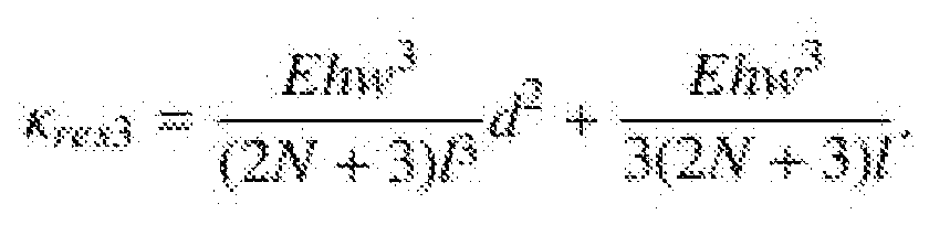
- the associated resonance frequency f res and moment of inertia J depend on the distance of the seismic mass from the axis of rotation.
- the dependency may be estimated with
- K res corresponds to the spring constant of a parasitic rotation mode, / the moment of inertia, w the width of the rotating seismic mass, / the length of the seismic mass and r the distance of the axis of rotation from a parallel axis passing through the center of the seismic mass.
- the spring constant K res of the parasitic mode can be estimated with y-direction spring constant k y of a rotated meander spring; where d is the distance from the end of the spring to the axis of rotation of the parasitic mode.
- k y may be estimated as: where E is the elastic modulus, h is thickness, w is width and / is length of the spring. N is the number of meanders in the spring.
- the spring constant of the measurement mode can be estimated with
- G is the shear modulus of the spring material.
- the ratio of the resonance modes of the measurement mode and the parasitic mode may thus be estimated as:
- equation (3) When distance d is small (approaches zero), equation (3) must be complemented with a correction term:
- the block chart of Figure 2 illustrates a simplified sensor structure configuration with a seismic mass 3 suspended by a spring structure 2, 4, 5, 6 to the anchor 1.
- the spring structure extends from the seismic mass 3 to the anchor 1, and at least part of the spring structure is formed by a side arm 4 that extends in the spring structure in a direction parallel to the axis of rotation of the seismic mass and is attached to one end of the spring.
- the mode of the parasitic resonances can be significantly increased, and thus effectively isolated from the measured modes by increasing the parameter d of equation (8).
- Said side arm 4 and the shoulder means 6 are attached to the spring 2 and the seismic mass 3, so that the shoulder means 6 with the side arm 4 so designed makes the structure stiffer against unwanted modes of vibrations.
- just one combination of side arm 4 and shoulder means 6 is shown in Figure 2, a skilled man in the art understands that at least two sets of side arms and/or shoulder means can be used for making the structure even stiffer against unwanted vibrations.
- this may be achieved with a first set of dimensions of said side arm 4 and/or shoulder means 6 and in another embodiment variant with a second set of dimensions of said side arm 4 and/or shoulder means 6.
- said first and second set of dimensions may be parameterized in a similar manner, and in another embodiment said first and second set of dimensions may be parameterized differently, to kill different modes of unwanted vibrations.
- the second set of shoulder means 6 and side arm 4 may be attached to the seismic mass symmetrically in respect of the first pair, and in another embodiment non-symmetrically.
- the shoulder means 6 may be directed away from the side arm, for example to an opposite direction, as shown with the shoulder means 6 in Figure 2.
- the shoulder means 6 and the side arm 4 may be integrated into one structure, making the shape of L to resemble the shape of J.
- the spring 2 may be integrated into the spring structure, as a thinner part of the integrated structure.
- the symmetrically attached sets 4,6 can be differently dimensioned for their mechanical length, width and thickness (not denoted in the figure) to yield a spring constant that characterizes the stiffening of the spring structure 2,4,6, to clean the measured vibration from unwanted vibration modes.
- the side arm 4 extends into a lever arm that transfers the parasitic rotational movement axis further away from the end of the spring.
- the momentum thus increases and the spring structure more effectively resists vibrations in unwanted directions.
- the longer the side arm the more effectively the first parasitic mode can be increased and thereby separated from the signal generating vibration mode.
- the springs must be aligned with the axis of rotation of the seismic mass, so the role of the shoulder means is to connect the side arm to the end of the spring, when the anchoring does not allow the side arm to be aligned with the spring.
- the shoulder means are dimensioned to extend only to a distance that allows movement of the side arm without touching the anchor 1.
- Figures 3A and 3B illustrate further embodiments of sensor structures and different anchoring mechanisms with embodiments where the springs are supported to a single anchor 1.
- the side arm 4 extends between the pivoting seismic mass and the end of the spring, as in Figure 2, and the shoulder means 6 is used to turn from the side arm 4 to other direction, perpendicular to it, for attaching the spring 2 to the side arm 4, so to form a stiffening spring structure 2, 4, 6.
- the anchor is an elongated element that extends along the axis of rotation and inside the seismic mass 3.
- Figure 3B illustrates an alternative embodiment, where the anchoring allows the side arm to be aligned with the springs such that the shoulder means 6 is not necessary.
- the distance between parasitic rotational movement axis and the end of a spring 2 may be increased by fixing one end of the side arm 4 to the anchor 1 and the other end to the spring, as shown in Figure 3B.
- one end of the side arm may be fixed to the anchor and the other to the end of the spring 2.
- the dashed side arm 4 and the dashed spring 2 in the other side of the anchor 1 illustrate that the elements are mutually optional in their respective embodiments.
- a sensor structure of Figure 3B may comprise two side arms, symmetrically set in respect to opposite sides of the anchor 1.
- the side arm configurations in different siders of the anchor may also be mutually different.
- single side 4 arm constructions can be used, wherein on one side of the anchor is side arm and on the other side a spring 2.
- Figure 4 illustrates an embodiment where capacitive detection of the motion is implemented with two different seismic masses Zl and Z2.
- elements Zl and Z2 may be implemented as differential structures and be arranged to a specific symmetry to implement a double differential detection structure.
- the term differential in the context of these embodiments means that, for example, a differential operation comprises a diminishing first quantity at a first location and an increasing second quantity at a second location coupled so that said diminishing and increasing occur because of the same operation. In differential detection both the first quantity and the second quantity are used to generate detection results of the operation.
- An example of such a structure is a capacitor pair that has two electrodes, each in a potential, and a common electrode in a ground potential.
- the electrodes may be arranged so that when the two electrodes pivot around an axis the distance of these electrodes to the common ground electrode changes, one capacitance increases and the other decreases.
- Such construction is achieved when the mechanical coupling is made with a rigid object that is common to the two pivoting electrodes.
- double differential in the context of these embodiments means that, for example, there is another differentially coupled pair of quantities, third quantity at a third location and an increasing fourth quantity at a fourth location that behave the same way as explained in the context of differential for the first quantity at a first location and a increasing second quantity at a second location, but with a phase sift in respect to the pair of first quantity and second quantity.
- double differential detection the first quantity, the second quantity, the third quantity and the fourth quantity are used in pairs to generate detection results of the operation.
- the elements Zl and Z2 are supported to a single anchor, each with a respective spring structure to provide separate axes of rotation.
- the first and second quantities of double differential detection refer to capacitances created by electrodes on a moving element Zl, and third and fourth quantities of double differential detection refer to capacitances created by electrodes on a moving element Z2.
- At least one of the springs of at least one of the seismic masses is connected to the seismic mass via a spring support structure that comprises a side arm 4, and a shoulder means 6.
- the element illustrated with dashing illustrates that the other spring may be an ordinary spring, or may comprise a further side arm that extends along the spring to further stiffen the spring support structure, as disclosed in Figure 3B.
- Figure 5 illustrates a further embodiment, where the elements Zl, Z2 are supported via the spring structure to three anchors (each denoted with 1) and pivot around a same axis of rotation aligned with the springs (each denoted with 2).
- the elements Zl, Z2 may be applied in combination to implement double differential detection.
- a structure that comprises a side arm 4 and a shoulder means 6.
- the side arm and the shoulder means are integral parts of the pivoting elements Zl, Z2.
- the side arm 4 extends advantageously in the direction of the spring 2, i.e. parallel to the axis of rotation, and the shoulder means 6 extend to a direction away from the spring 2, preferably perpendicular to the spring 2.
- the structure of Figure 5 is stiff in other directions than the measured rotation and effectively eliminates unwanted modes of vibration during detection of the measured rotation.
- the side arm and the shoulder means of one element Zl of the double differential detection is nested into the dimensions of the other element Z2 of the double differential detection, and vice versa. The advantage of the extended spring structure is therefore achieved with minimal use of space in the plane of the elements.
- FIG. 6 illustrates a further advantageous embodiment of a symmetric see-saw type of sensor structure, implemented with elements Zl and Z2 for double differential detection, as described above.
- the elements Zl, Z2 are supported via a spring structure to a single anchor 1, and are arranged to pivot around a same axis of rotation aligned with springs 2.
- each of the elements Zl again comprises a side arm 4 and a shoulder means 6, with which the distance between the center of the seismic mass of elements and the ends of the springs 2 that support the elements is increased, and the structure is made more rigid in directions of unwanted vibrations.
- the springs 2 are supported to the anchor 1 with an elongate spring support 7 that extends outward of the anchoring point and provides a static point of suspension to the springs along the axis of rotation.
- Figure 7 illustrates an embodiment of a 3d acceleration sensor that may comprise any of the see-saw type of MEMS structures described above.
- the sensor may comprise also X- and/or Y-direction detection cells, which can be implemented in a way well known to a person skilled in the art of MEMS sensors.
- the two seismic masses Zl and Z2 are also applicable for double differential detection with a configuration where the seismic masses are extended in the plane of the elements. Such configuration intensifies the movement and thereby improves sensitivity of the detection.
- Figure 8 illustrates different kind of embodiments that may comprise any of the see- saw type of MEMS structures described above.
- Letter S denotes a sensor or a sensor structure.
- Letter M denotes a sensor matrix that comprises a sensor or the sensor structure as embodied.
- Letter D denotes a device that comprises a sensor or a sensor matrix as embodied. Although exemplary four sensors are indicated, three sensor in one position and one sensor in another that is different than first said position, as an example, the number of sensors or their type is not limited only to the indicated example. The number and/or position of the sensor matrixes in the device are neither limited to the shown example only.
- the letter combination Ar denotes an arrangement or a system that comprises at least one of the embodied sensor structures in the device D, and/or a device G according to an embodiment of the invention.
- the exceptional position of the letters S and M in some embodiments illustrates to a skilled man in the art that the sensor structures in various embodiments can be operated independently on the true position of the master device, whose acceleration is monitored with the sensor structure comprising cells and/or flip-flops in the sensor S.
Landscapes
- Physics & Mathematics (AREA)
- General Physics & Mathematics (AREA)
- Measurement Of Mechanical Vibrations Or Ultrasonic Waves (AREA)
- Pressure Sensors (AREA)
- Geophysics And Detection Of Objects (AREA)
- Gyroscopes (AREA)
Abstract
Description


Claims
Priority Applications (6)
| Application Number | Priority Date | Filing Date | Title |
|---|---|---|---|
| CA2860505A CA2860505A1 (en) | 2012-01-12 | 2013-01-11 | A vibration tolerant accelaration sensor structure |
| KR1020147022222A KR101944235B1 (en) | 2012-01-12 | 2013-01-11 | A vibration tolerant accelaration sensor structure |
| SG11201403699XA SG11201403699XA (en) | 2012-01-12 | 2013-01-11 | A vibration tolerant accelaration sensor structure |
| CN201380014121.5A CN104204815B (en) | 2012-01-12 | 2013-01-11 | A vibration tolerant acceleration sensor structure |
| JP2014551658A JP6143789B2 (en) | 2012-01-12 | 2013-01-11 | Vibration-resistant acceleration sensor structure |
| EP13736230.7A EP2802883B1 (en) | 2012-01-12 | 2013-01-11 | A vibration tolerant accelaration sensor structure |
Applications Claiming Priority (2)
| Application Number | Priority Date | Filing Date | Title |
|---|---|---|---|
| FI20125035 | 2012-01-12 | ||
| FI20125035 | 2012-01-12 |
Publications (1)
| Publication Number | Publication Date |
|---|---|
| WO2013104828A1 true WO2013104828A1 (en) | 2013-07-18 |
Family
ID=48781083
Family Applications (1)
| Application Number | Title | Priority Date | Filing Date |
|---|---|---|---|
| PCT/FI2013/050025 WO2013104828A1 (en) | 2012-01-12 | 2013-01-11 | A vibration tolerant accelaration sensor structure |
Country Status (9)
| Country | Link |
|---|---|
| US (1) | US9366690B2 (en) |
| EP (1) | EP2802883B1 (en) |
| JP (1) | JP6143789B2 (en) |
| KR (1) | KR101944235B1 (en) |
| CN (1) | CN104204815B (en) |
| CA (1) | CA2860505A1 (en) |
| SG (1) | SG11201403699XA (en) |
| TW (1) | TWI607956B (en) |
| WO (1) | WO2013104828A1 (en) |
Cited By (3)
| Publication number | Priority date | Publication date | Assignee | Title |
|---|---|---|---|---|
| EP3151018A1 (en) * | 2015-09-29 | 2017-04-05 | NXP USA, Inc. | Mems sensor with reduced cross-axis sensitivity |
| WO2019152075A3 (en) * | 2017-11-30 | 2019-10-17 | Invensense, Inc. | Asymmetric out-of-plane accelerometer |
| US11867714B2 (en) | 2021-07-05 | 2024-01-09 | Murata Manufacturing Co., Ltd. | Accelerometer with two seesaws |
Families Citing this family (10)
| Publication number | Priority date | Publication date | Assignee | Title |
|---|---|---|---|---|
| FI127000B (en) * | 2015-06-26 | 2017-09-15 | Murata Manufacturing Co | MEMS sensor |
| KR101915954B1 (en) * | 2016-06-29 | 2018-11-08 | 주식회사 신성씨앤티 | MEMS based 3-axis accelerometer |
| US10126129B2 (en) | 2016-07-11 | 2018-11-13 | Nxp Usa, Inc. | Vibration and shock robust gyroscope |
| DE102016220510A1 (en) | 2016-10-19 | 2018-04-19 | Robert Bosch Gmbh | Micromechanical z-accelerometer |
| DE102017218595A1 (en) | 2016-10-19 | 2018-04-19 | Robert Bosch Gmbh | Micromechanical spring for a sensor element |
| US10759656B2 (en) * | 2017-09-29 | 2020-09-01 | Apple Inc. | MEMS sensor with dual pendulous proof masses |
| JP6870761B2 (en) * | 2019-05-15 | 2021-05-12 | 株式会社村田製作所 | Robust Z-axis accelerometer |
| JP2021006794A (en) | 2019-06-28 | 2021-01-21 | セイコーエプソン株式会社 | Inertial sensor, electronic apparatus, and movable body |
| EP4116718A1 (en) * | 2021-07-05 | 2023-01-11 | Murata Manufacturing Co., Ltd. | Seesaw accelerometer |
| CN114487482B (en) * | 2022-01-14 | 2024-08-16 | 瑞声开泰科技(武汉)有限公司 | Acceleration sensor |
Citations (4)
| Publication number | Priority date | Publication date | Assignee | Title |
|---|---|---|---|---|
| US20060185433A1 (en) * | 2005-02-18 | 2006-08-24 | Honeywell International, Inc. | MEMS teeter-totter accelerometer having reduced non-linearty |
| US20090223277A1 (en) * | 2008-03-05 | 2009-09-10 | Colibrys Sa | Vibrating gyroscope with quadrature signals reduction |
| US20100107763A1 (en) * | 2008-10-30 | 2010-05-06 | Freescale Semiconductor, Inc. | Transducer with decoupled sensing in mutually orthogonal directions |
| US20100147073A1 (en) * | 2008-12-16 | 2010-06-17 | Honeywell International Inc. | Systems and methods for an inertial sensor suspension that minimizes proof mass rotation |
Family Cites Families (17)
| Publication number | Priority date | Publication date | Assignee | Title |
|---|---|---|---|---|
| US6860151B2 (en) * | 2003-02-07 | 2005-03-01 | Honeywell International Inc. | Methods and systems for controlling movement within MEMS structures |
| US6843127B1 (en) * | 2003-07-30 | 2005-01-18 | Motorola, Inc. | Flexible vibratory micro-electromechanical device |
| US7240552B2 (en) | 2005-06-06 | 2007-07-10 | Bei Technologies, Inc. | Torsional rate sensor with momentum balance and mode decoupling |
| FR2898884B1 (en) * | 2006-03-27 | 2008-05-02 | Commissariat Energie Atomique | INERTIAL MICRO-SENSOR RESONANT TO VARIABLE THICKNESS PRODUCED IN SURFACE TECHNOLOGIES |
| US8413509B2 (en) * | 2008-04-14 | 2013-04-09 | Freescale Semiconductor, Inc. | Spring member for use in a microelectromechanical systems sensor |
| FI122397B (en) | 2008-04-16 | 2011-12-30 | Vti Technologies Oy | A vibrating micromechanical angular velocity sensor |
| US8499629B2 (en) * | 2008-10-10 | 2013-08-06 | Honeywell International Inc. | Mounting system for torsional suspension of a MEMS device |
| FI20095201A0 (en) | 2009-03-02 | 2009-03-02 | Vti Technologies Oy | Oscillating micromechanical angular velocity sensor |
| JP2010210424A (en) * | 2009-03-10 | 2010-09-24 | Panasonic Electric Works Co Ltd | Acceleration sensor |
| US8256290B2 (en) * | 2009-03-17 | 2012-09-04 | Minyao Mao | Tri-axis angular rate sensor |
| WO2010138717A1 (en) | 2009-05-27 | 2010-12-02 | King Abdullah University Of Science And Technology | Mems mass spring damper systems using an out-of-plane suspension scheme |
| US8307710B2 (en) | 2009-07-09 | 2012-11-13 | Honeywell International Inc. | Translational mass in-plane MEMS accelerometer |
| ITTO20090597A1 (en) * | 2009-07-31 | 2011-02-01 | St Microelectronics Srl | Z AXIS MICROELETTROMECHANICAL DETECTION STRUCTURE WITH REDUCED THERMAL DERIVATIONS |
| IT1395419B1 (en) | 2009-09-07 | 2012-09-14 | Milano Politecnico | ACCONEROMETER RESONATING MEMS WITH IMPROVED ELECTRIC CHARACTERISTICS |
| FR2957414B1 (en) | 2010-03-15 | 2012-09-28 | Commissariat Energie Atomique | FORCE SENSOR WITH REDUCED NOISE |
| US8516886B2 (en) * | 2010-04-30 | 2013-08-27 | Qualcomm Mems Technologies, Inc. | Micromachined piezoelectric X-Axis gyroscope |
| US8839670B2 (en) * | 2010-11-24 | 2014-09-23 | Invensense, Inc. | Anchor-tilt cancelling accelerometer |
-
2013
- 2013-01-11 CN CN201380014121.5A patent/CN104204815B/en active Active
- 2013-01-11 CA CA2860505A patent/CA2860505A1/en not_active Abandoned
- 2013-01-11 TW TW102101076A patent/TWI607956B/en active
- 2013-01-11 EP EP13736230.7A patent/EP2802883B1/en active Active
- 2013-01-11 WO PCT/FI2013/050025 patent/WO2013104828A1/en active Application Filing
- 2013-01-11 US US13/739,220 patent/US9366690B2/en active Active
- 2013-01-11 SG SG11201403699XA patent/SG11201403699XA/en unknown
- 2013-01-11 KR KR1020147022222A patent/KR101944235B1/en active IP Right Grant
- 2013-01-11 JP JP2014551658A patent/JP6143789B2/en active Active
Patent Citations (4)
| Publication number | Priority date | Publication date | Assignee | Title |
|---|---|---|---|---|
| US20060185433A1 (en) * | 2005-02-18 | 2006-08-24 | Honeywell International, Inc. | MEMS teeter-totter accelerometer having reduced non-linearty |
| US20090223277A1 (en) * | 2008-03-05 | 2009-09-10 | Colibrys Sa | Vibrating gyroscope with quadrature signals reduction |
| US20100107763A1 (en) * | 2008-10-30 | 2010-05-06 | Freescale Semiconductor, Inc. | Transducer with decoupled sensing in mutually orthogonal directions |
| US20100147073A1 (en) * | 2008-12-16 | 2010-06-17 | Honeywell International Inc. | Systems and methods for an inertial sensor suspension that minimizes proof mass rotation |
Non-Patent Citations (1)
| Title |
|---|
| See also references of EP2802883A4 * |
Cited By (4)
| Publication number | Priority date | Publication date | Assignee | Title |
|---|---|---|---|---|
| EP3151018A1 (en) * | 2015-09-29 | 2017-04-05 | NXP USA, Inc. | Mems sensor with reduced cross-axis sensitivity |
| WO2019152075A3 (en) * | 2017-11-30 | 2019-10-17 | Invensense, Inc. | Asymmetric out-of-plane accelerometer |
| US10732196B2 (en) | 2017-11-30 | 2020-08-04 | Invensense, Inc. | Asymmetric out-of-plane accelerometer |
| US11867714B2 (en) | 2021-07-05 | 2024-01-09 | Murata Manufacturing Co., Ltd. | Accelerometer with two seesaws |
Also Published As
| Publication number | Publication date |
|---|---|
| JP2015509189A (en) | 2015-03-26 |
| CN104204815B (en) | 2017-05-17 |
| KR101944235B1 (en) | 2019-01-31 |
| CN104204815A (en) | 2014-12-10 |
| EP2802883A4 (en) | 2015-08-05 |
| EP2802883B1 (en) | 2016-07-13 |
| EP2802883A1 (en) | 2014-11-19 |
| TWI607956B (en) | 2017-12-11 |
| JP6143789B2 (en) | 2017-06-07 |
| CA2860505A1 (en) | 2013-07-18 |
| KR20140111031A (en) | 2014-09-17 |
| US20130192362A1 (en) | 2013-08-01 |
| TW201339082A (en) | 2013-10-01 |
| US9366690B2 (en) | 2016-06-14 |
| SG11201403699XA (en) | 2014-07-30 |
Similar Documents
| Publication | Publication Date | Title |
|---|---|---|
| US9366690B2 (en) | Vibration tolerant acceleration sensor structure | |
| US9279825B2 (en) | Acceleration sensor structure and use thereof | |
| US9452921B2 (en) | Gyroscope structure and gyroscope | |
| US9239339B2 (en) | Acceleration sensor and method for operating an acceleration sensor | |
| KR101699573B1 (en) | Double-axial, impact-resistant yaw rate sensor comprising nested, linearly oscillating seismic elements | |
| US10330476B2 (en) | Angular rate sensor with in-phase motion suppression structure | |
| US20150330783A1 (en) | Systems and methods for mems gyroscope shock robustness | |
| CN107771287B (en) | MEMS sensor | |
| CN101443629A (en) | Rate-of-rotation sensor having a coupling bar | |
| JP6583547B2 (en) | Improved microelectromechanical accelerometer | |
| US11105828B2 (en) | Microelectromechanical device for out-of-plane motion detection | |
| CN108020686B (en) | MEMS triaxial accelerometer with improved configuration | |
| US20130239679A1 (en) | Three-axis gyroscope | |
| US11846509B2 (en) | Three-axis rotation rate sensor including a substrate and a double rotor | |
| CN112703406A (en) | Z-axis accelerometer with improved sensitivity | |
| JP2018531377A6 (en) | Improved microelectromechanical accelerometer | |
| CN112485470A (en) | Low noise multi-axis MEMS accelerometer | |
| US20190033341A1 (en) | Mems-based three-axis acceleration sensor | |
| TWI663403B (en) | Capacitive micromechanical accelerometer and method for performing a self-test in the same | |
| CN109761184B (en) | Micromechanical Z inertial sensor and method for manufacturing same | |
| US10598686B2 (en) | Micromechanical z-acceleration sensor |
Legal Events
| Date | Code | Title | Description |
|---|---|---|---|
| 121 | Ep: the epo has been informed by wipo that ep was designated in this application |
Ref document number: 13736230 Country of ref document: EP Kind code of ref document: A1 |
|
| ENP | Entry into the national phase |
Ref document number: 2860505 Country of ref document: CA |
|
| ENP | Entry into the national phase |
Ref document number: 2014551658 Country of ref document: JP Kind code of ref document: A |
|
| NENP | Non-entry into the national phase |
Ref country code: DE |
|
| REEP | Request for entry into the european phase |
Ref document number: 2013736230 Country of ref document: EP |
|
| WWE | Wipo information: entry into national phase |
Ref document number: 2013736230 Country of ref document: EP |
|
| ENP | Entry into the national phase |
Ref document number: 20147022222 Country of ref document: KR Kind code of ref document: A |