WO2013104229A1 - 跨层排水冲厕系统 - Google Patents
跨层排水冲厕系统 Download PDFInfo
- Publication number
- WO2013104229A1 WO2013104229A1 PCT/CN2012/086418 CN2012086418W WO2013104229A1 WO 2013104229 A1 WO2013104229 A1 WO 2013104229A1 CN 2012086418 W CN2012086418 W CN 2012086418W WO 2013104229 A1 WO2013104229 A1 WO 2013104229A1
- Authority
- WO
- WIPO (PCT)
- Prior art keywords
- pipe
- drainage
- floor
- washing
- flushing
- Prior art date
Links
Images

Classifications
-
- E—FIXED CONSTRUCTIONS
- E03—WATER SUPPLY; SEWERAGE
- E03C—DOMESTIC PLUMBING INSTALLATIONS FOR FRESH WATER OR WASTE WATER; SINKS
- E03C1/00—Domestic plumbing installations for fresh water or waste water; Sinks
- E03C1/12—Plumbing installations for waste water; Basins or fountains connected thereto; Sinks
- E03C1/122—Pipe-line systems for waste water in building
Definitions
- the invention relates generally to an indoor drainage system for a multi-storey residential building and other civil buildings, in particular to a cross-layer drainage flushing system.
- the households on this floor collect the domestic wastewater of the residents on the floor or the upper floors.
- the waste water is purified, disinfected and stored in the container.
- the container is placed or mounted.
- the wastewater is pumped or self-flowing into the toilet tank.
- This technical container Squeezing the indoor space, the operating system is complicated, and it is easy to pollute the indoor environment and it is difficult to popularize.
- toilets and squatting pans are used in the toilets of civil buildings.
- the water consumption is about 9 liters per person. 6 liters of water is a water-saving toilet. According to the principle of siphonic toilets, it is difficult to make new breakthroughs. Although the water toilet has reduced the amount of flushing water to a certain extent, the amount of water saved is limited.
- the object of the present invention is to provide a cross-layer drainage flushing in order to overcome the above-mentioned deficiencies.
- the object of the invention is achieved by a technical solution: a cross-layer drainage flushing system comprising: a spacer type sitting Toilet, drainage main riser, drainage auxiliary riser, tee, P-type trap, flushing drainage pipe, washing drainage pipe, washing drainage pipe, vent pipe; domestic wastewater of each floor
- the flushing drainage horizontal pipe is connected to the drainage main riser under the floor
- the floor drain, bathtub and mop pool on the previous floor are connected to the washing and draining trunk pipe, the washing and draining trunk pipe is connected to the drainage auxiliary riser, and the drainage auxiliary riser is connected to the tee of the floor through the lower layer.
- the three links are connected to the toilet in turn.
- P-type trap, flushing and draining main pipe, drainage main riser; washing tank and washing pool on this floor are connected to the washing and draining trunk pipe, and the washing and draining horizontal pipe is connected horizontally to the floor of the three-way, three-way Connect the toilet, P-type trap, and rush Dry horizontal drainage pipe, the drainage of the main riser.
- the two ends of the flushing and draining pipe are respectively connected to the floor, that is, the main drainage pipe under the plate, and the P-type water trap, and the connection method is a figure-shaped and T-shaped type, and the P-type water trap is a doorless type, water
- the sealing part is provided with an anti-condensation device; the P-type trap has a three-way and a baffle type toilet in turn.
- the washing and draining horizontal pipe is provided with a sweeping port at the beginning; the washing and draining pipe is provided with a branching venting pipe, and the branching venting pipe is connected with the total venting pipe; the end of the washing and draining horizontal pipe is provided with an elbow to connect the drainage auxiliary riser, and the drainage auxiliary riser Downstream through the floor slab to connect the short pipe, the short pipe connects the three-way middle mouth.
- the horizontal position of the washing and draining horizontal pipe is between the washing and draining horizontal pipe and the bottom of the plate; the top of the washing and draining pipe is provided with a branching venting pipe, the branching venting pipe is extended to the roof; the washing and draining pipe is horizontally drained The cleaning end is provided at the beginning; the end of the washing and draining pipe is horizontally connected to the short pipe, and the short pipe is connected to the middle of the tee.
- the drainage main riser is provided with three-way on each floor, the three-way middle mouth is connected with the rushing drainage horizontally-main pipe; the rushing drainage horizontal-drying pipe is connected with the P-type water trap or the S-type water trap; the drainage main riser single floor Establish a pipe inspection port; the lower pipe of the main drainage pipe connects the outdoor well.
- the two ends of the drainage auxiliary riser respectively communicate with the floor short pipe and the washing drainage horizontal pipe on the upper floor; the drainage auxiliary pipe establishes a pipe inspection port layer by layer.
- the upper vent pipe has a pipe top extending to the top roof, and the lower pipe mouth is connected to the atmosphere; the total vent pipe is provided with three links on each floor, and the three-way middle port is connected with the branch vent pipe; the height of the three-way middle port is higher than the sanitary floor of the floor Sanitary ware.
- the short pipe ends are respectively connected with the three-way and the drainage auxiliary riser; the short pipe section is provided with a three-way, the middle of the three-way pipe is horizontal or vertical, and the washing and draining drainage horizontal pipe is connected.
- the lower nozzle of the three-way is connected with the pipe section of the upper pipe of the P-type trap; the middle of the three-way is connected with the short pipe, the axial rotation is three-way, corresponding to the connection of the drainage auxiliary pipe; the upper pipe of the three-way pipe is connected with the pipe section Baffle type toilet.
- the partition plate of the baffle type toilet is a double-layer plate, and the two-layer plate is elastically connected; the baffle is hinged to the rectangular drain pipe through the through shaft; the pin is supported by the sliding bracket of the pin and slides back and forth, and the pin movement is controlled back and forth.
- the partition is opened or closed and is electrically or manually controlled.
- the cross-layer drainage flushing system of the invention has the remarkable water-saving effect, is simple and effective, and does not consume energy. No pollution, no blockage, low cost of engineering implementation, one investment will always benefit, no investment, can get rid of the high cost, energy consumption, cumbersome operation, easy pollution, popularization difficulties No operation or management is required.
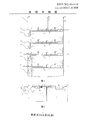
- Figure 1 is a perspective view of the drainage pipe of the present invention
- Figure 2 is a plan view of the drainage pipe
- Figure 3 is a structural view of a bulkhead type toilet.
- A is the toilet and the bathroom C is the kitchen B is the floor
- 24 is a rectangular drain pipe fixing bracket
- 26 is a sliding bracket for the pin
- a cross-layer drainage flushing system as shown in FIG. 1 and FIG. 2, includes: the toilet bowl 3 is a baffle type toilet, and the domestic wastewater of each floor is drained by a flushing draining pipe 9, washing and draining horizontally.
- the toilet bowl 3, the P-type trap 16, the flushing drain pipe 9, and the drain main riser 1 are connected.
- the two ends of the flushing and draining trunk pipe 9 respectively communicate with the drainage main riser 1 and the P type trap 16 , and the connection method is a single-shaped and T-shaped, and the P-type water trap 16 is a doorless type, and the water seal
- the anti-condensation device is arranged at the position; the upper nozzle of the P-type trap 16 is connected to the tee 17 and the baffle type toilet 3 in sequence.
- the washing and draining horizontal pipe 10 is provided with a cleaning port 13 at the beginning, the washing and draining pipe 10 is provided with a branching venting pipe 15, the branching venting pipe 15 is connected with the total venting pipe 14, and the end of the washing and draining horizontal pipe 10 is provided with an elbow connecting drainage pair.
- the riser 2, the drainage auxiliary riser 2 descends through the floor to connect the short pipe 18, and the short pipe 18 communicates with the middle of the tee 17 port.
- the horizontal position of the washing and draining horizontal pipe 11 is between the washing and draining pipe 10 and the bottom of the plate; the top of the washing and draining pipe 11 is provided with a branching pipe 15 and the branching pipe 15 is extended to the roof;
- the cleaning outlet 13 is provided at the beginning of the trough drainage main pipe 11; the end of the washing drainage main pipe 11 is horizontally connected to the short pipe 18, and the short pipe 18 is connected to the middle of the tee 17 port.
- the drainage main riser 1 is provided with a three-way on each floor, the three-way middle mouth is connected to the rushing drainage horizontally-drying pipe 9; the rushing drainage horizontal-drying pipe 9 is connected to the P-type water trap 16 or the S-type water trap;
- the pipe inspection port is set up on the single floor of the riser 1; the lower pipe of the main drainage pipe 1 is connected to the outdoor well.
- the two ends of the drainage auxiliary riser 2 respectively communicate with the short pipe 18 and the washing and draining horizontal pipe 10; the drainage auxiliary pipe 2 establishes the pipe inspection port 12 layer by layer.
- the upper vent pipe 14 has a pipe top extending to the top roof, and the lower pipe mouth is connected to the atmosphere; the total vent pipe 14 is provided with a tee on each floor, and the three-way middle port is connected to the branch vent pipe 15, and the height of the three-way middle port is higher than Floor sanitary ware.
- the short pipe 18 is respectively connected with the three-way 17 and the drainage auxiliary riser 2; the short pipe 18 is provided with a three-way pipe, and the middle of the three-way pipe is horizontal or vertical, and communicates with the washing and draining main pipe 11.
- the lower nozzle of the three-way 17 is connected with the pipe section of the upper pipe of the P-type trap 16; the middle of the three-way 17 is connected with the short pipe 18, and the three-way 17 is axially rotated, corresponding to the connection of the drainage auxiliary pipe 2; 17
- the upper pipe mouth is provided with a pipe section connected to the bulkhead type toilet 3.
- the partition plate 20 of the baffle type toilet 3 is a double-layer plate, and the two-layer plate is elastically connected; the partition plate 20 is hinged with the rectangular drain pipe 21 through the through shaft 27; the pin 22 passes through the sliding bracket 25 of the pin and 26 supports and slides back and forth, and the pin 22 moves forward and backward to control the partition 20 to be opened or closed, and is electrically or manually controlled.
- the process of draining and flushing is: (1) After the toilet is closed, the toilet partition is opened, and the sewage in the toilet bowl is gravity-dropped into the water seal of the P-type trap, and the toilet is washed with one liter of water. In the pool, when the toilet partition is closed, the remaining part of the water is 0.47 liters, which remains on the partition to form a water purification seal. (2) The sewage that falls into the P-type trap is made up of 1.5 liters of the volume of the water-sealed product and is mixed and dispersed in the water seal. (3) The washing water discharge on the upper floor and the floor is entered into the pipe water seal through the drainage auxiliary riser and the washing drainage pipe.
- the gravity water formed by the cross-layer drainage acts on the sewage and sewage remaining in the pipe water seal.
- the pipe water seal is the only passage for the washing water discharge, which can maintain sufficient water head and water volume to replace the sewage and dirt stored in the water seal of the pipeline to ensure the automatic and orderly operation of the system. "People sit on the top and the water flows down” can sum up the full meaning of the drainage and flushing. People will enjoy a new feeling when they are going to the toilet.
- the working condition of the bulkhead type toilet 3 is such that a small amount of clean water is stored in the sealed state on the partition plate 20, and the pin 22 presses the lower plate of the partition plate 20, and the elastic structure between the plates is pressed.
- the plate and the upper plate extrude the nozzle gasket 23 to achieve a sealing effect, and the front and rear sliding of the driving pin control the opening and closing of the partition plate 20.
- the baffle type toilet has structurally eliminated the water sealing device of the whole water trap, and uses a pipeline type P-type trap to be a water sealing device underneath, and the sewage dirt is dropped to the P type by gravity. The bottom of the water bend. At this time, under the toilet partition is a 70 cm deep pipe hole. It can be visually observed that the washing water from the floor and the upper floor flows through the tee into the P-type trap, and the gravity water flows through the bottom seal of the P-type trap. Entrain sewage dirt into the main drain pipe.
- the washing water is further distributed into two lines of washing and draining pipe and washing and draining pipe, and two water sources are adopted.
- the experiment proves that the height of the water head is 0.9 m, the wastewater is 8 liters, the diameter of the irrigation pipe is 50 mm, and the P-type trap is connected in a word.
- the washing and draining pipe is arranged, and the sanitary ware washing pool and the washing tank of the high head are selected to be connected with each other, thereby making up for the defect that the top and middle floors are empty without waste water source and waste water source, and the cross-layer drainage is improved.
- the theory and method of flushing is improved.
- the experiment proves that the water-saving effect of the cross-layer drainage flushing system of the invention is remarkable, simple and effective, no energy consumption, no pollution, no pipe blocking, low cost of engineering implementation, one-time investment for permanent benefit, and getting rid of the current flushing method.
- the utility model has the advantages of high cost, high energy consumption, cumbersome operation, easy pollution, difficulty in popularization, and no operation and management.
- the cross-layer drainage and flushing system of the invention has remarkable water-saving effect, and the method for water-saving and pollution-reducing is simple and effective, does not consume energy, does not pollute, does not block the pipe, does not require operation and management, and is low in engineering cost, and involves construction. Drainage pipes and fittings are standardized products commonly used in the market.
- the same type of toilets manufactured by the principle of baffle type toilets can be used in the system instead of one-time installation or retrofit installation, which will benefit permanently from the current flushing method. There are high cost, high energy consumption, cumbersome operation, easy pollution, and difficult to spread.
- the cross-deck drainage flushing system is a common drainage pipe system that automatically flushes the sewage of the next floor by using the washing water discharged from the top layer to the first layer in layers, which is an integral part of the main building, and the household can benefit freely or paidly. There is no interest relationship between the households.
Abstract
一种跨层排水冲厕系统,包括:隔板式坐便器(3)、排水主立管(1)、排水副立管(2)、三通(17)、P型存水弯(16)、冲便排水横干管(9)、洗涤排水横干管(10)、洗槽排水横干管(11)、透气管(14、15);各楼层的生活废水通过冲便排水横干管(9)、洗涤排水横干管(10)、洗槽排水横干管(11)与排水主立管(1)连通;冲便排水横干管(9)在本楼层即楼板下连通排水主立管(1);上一楼层的地漏(5)、浴缸(6)、拖布池(7)连通洗涤排水横干管(10),洗涤排水横干管(10)连通排水副立管(2),排水副立管(2)下行跨层连通本楼层的三通(17);三通(17)依次连通坐便器(3)、P型存水弯(16)、冲便排水横干管(9)、排水主立管(1);本楼层的洗槽(8)、洗漱池(4)连通洗槽排水横干管(11),洗槽排水横干管(11)水平连通本楼层的三通(17),三通(17)依次连通坐便器(3)、P型存水弯(16)、冲便排水横干管(19)、排水主立管(1)。
Description
技术领域
本发明主要涉及多层住宅建筑及其它民用建筑的室内排水系统,具体是一种跨层排水冲厕系统。
背景技术
近来年,我国城镇化进程加快,加剧了水资源的消耗,由于水资源短缺,不断出现很多节水冲厕的方式方法,主要有中水回用冲厕技术,废水存储冲厕技术和节水坐便器技术等。
1、中水回用冲厕技术
中水回用冲厕在我国已推广应用十年,中水就地制取或异地配送都需要很高的设备和管线投资,需要占用一定量的土地,需要不间断的管理运营成本,还时而因污水处理的深度欠缺伴有异味,遭遇用户排斥,推广难度较大。
2、废水存储冲厕技术
本楼层住户收集本楼层或上楼层住户的生活废水,废水经过净化,消毒处理后存放在容器内,容器落地或是挂装,废水通过泵送或自流的方式进入坐便器水箱,这项技术容器挤占室内空间,运行系统繁杂,容易污染室内环境,难以普及。
3、节水坐便器技术
目前民用建筑的卫生间多采用坐便器和蹲便器,耗水量为一人次9升左右,6升水即为节水型坐便器,根据虹吸式坐便器的制作原理,很难再有新的突破,节水坐便器虽然在一定程度上减少了冲厕水量,但节水量有限。
为了解决上述问题,本发明人于2006年申请专利号为ZL200620001920.6的实用新型专利,但是该专利技术据实际需求尚有不足之处:1、排水冲厕的顶层设计空缺;2、排水冲厕在中间楼层空居时,其下一楼层的住户会因此而中断使用。
发明内容
本发明目的在于:为了克服上述的不足之处,提供了一种跨层排水冲厕本发明目的是通过这样的技术方案实现的:一种跨层排水冲厕系统,它包括:隔板式坐便器、排水主立管、排水副立管、三通、P型存水弯、冲便排水横干管、洗涤排水横干管、洗槽排水横干管、透气管;各楼层的生活废水通过冲便排水横干管、洗涤排水横干管、洗槽排水横干管分层分流跨层连通排水主立管;所述的冲便排水横干管在本楼层即板下连通排水主立管;上一楼层的地漏、浴缸、拖布池连通洗涤排水横干管,洗涤排水横干管连通排水副立管,排水副立管下行跨层连通本楼层的三通;三通依次连通坐便器、P型存水弯、冲便排水横干管、排水主立管;本楼层的洗槽、洗漱池连通洗槽排水横干管,洗槽排水横干管水平连通本楼层的三通,三通依次连通坐便器、P型存水弯、冲便排水横干管、排水主立管。
所述的冲便排水横干管两端分别连通本楼层即板下排水主立管、P型存水弯,连通方法为一字形和T字型,P型存水弯为无门型,水封部位设置防结露装置;P型存水弯上管口依次连通三通、隔板式坐便器。
所述的洗涤排水横干管始端设清扫口;洗涤排水横干管设分支透气管,分支透气管连通总透气管;洗涤排水横干管末端设弯头连通排水副立管,排水副立管下行穿过本层楼板连通短管,短管连通三通中口。
所述的洗槽排水横干管水平位置在洗涤排水横干管与板底之间;洗槽排水横干管顶层干管设分支透气管,分支透气管伸顶屋面;洗槽排水横干管始端设清扫口;洗槽排水横干管末端水平连通短管,短管连通三通中口。
所述的排水主立管各楼层设三通,三通中口连通冲便排水横干管;冲便排水横干管连通P型存水弯或S型存水弯;排水主立管单数楼层设立管检查口;排水主立管下管口连通室外窨井。
所述的排水副立管两端分别连通本楼层即板下短管、上一楼层的洗涤排水横干管;排水副立管逐层设立管检查口。
所述的总透气管上管口伸顶屋面,下管口与大气连通;总透气管各楼层设三通,三通中口连通分支透气管;三通中口的高度高于所在楼层的卫生洁具。
所述的短管两端分别连通三通、排水副立管;短管管段设三通,三通中口呈水平或垂直,连通洗槽排水横干管。
所述的三通下管口与P型存水弯上管口设管段连通;三通中口连通短管,轴向转动三通,对应排水副立管连通;三通上管口设管段连通隔板式坐便器。
所述的隔板式坐便器的隔板为双层板,双层板间为弹性连通;隔板通过通轴与矩形排水管铰接;销钉通过销钉的滑动支架支撑并前后滑动,销钉前后运动控制隔板开启或关闭,采用电动或手动控制。
本发明跨层排水冲厕系统,具有节水效果显著,简单实效,不用耗能源
,不污染,不堵管,以工程化实施造价低廉,一次投资永远受益,不复加投资,可摆脱目前冲厕方法上存在的成本高,耗能,烦琐操作,易污染,普及难的困境,不需要操作和管理。
下面结合附图和实施例对本发明进一步说明:
附图说明
附图1:是本发明排水管道透视图;
附图2:是排水管道平面图;
附图3:是隔板式坐便器结构图。
编号说明
A为厕所和卫生间 C为厨房 B为楼板
1 为排水主立管 2 为排水副立管 3 为隔板式坐便器
4 为洗漱池 5 为地漏 6 为浴缸
7 为拖布池 8 为洗槽 9 为冲便排水横干管
10 为洗涤排水横干管 11 为洗槽排水横干管
12 为副立管检查口 13 为排水干管清扫口
14 为总透气管 15 为各楼层的分支透气管
16 为P型存水弯 17 为三通
18 为短管 19 为透气管帽
20 为隔板 21 为矩型排水管
22 为销钉 23 为圆形密封垫
24 为矩形排水管固定支架 25、26 为销钉的滑动支架
27 为通轴
具体实施方式
下面结合附图和实施例,对本发明的具体实施方式作进一步详细描述。以下实施例用于说明本发明,但不用来限制本发明的范围。
一种跨层排水冲厕系统,如附图1、附图2所示,它包括:坐便器3为隔板式坐便器,各楼层的生活废水通过冲便排水横干管9、洗涤排水横干管10、洗槽排水横干管11、分层分流跨层连通排水主立管1;所述的冲便排水横干管9连通排水主立管1;地漏5、浴缸6、拖布池7连通洗涤排水横干管10,洗涤排水横干管10连通排水副立管2,排水副立管2逐层下行连通三通17、三通17依次连通坐便器3、P型存水弯16、冲便排水横干管9、排水主立管1;洗槽8、洗漱池4、连通洗槽排水横干管11,洗槽排水横干管11逐层水平连通三通17、三通17依次连通坐便器3、P型存水弯16、冲便排水横干管9、排水主立管1。
所述的冲便排水横干管9两端分别连通排水主立管1、P型存水弯16,连通方法为一字形和T字型,P型存水弯16为无门型,水封部位设置防结露装置;P型存水弯16的上管口依次连通三通17,隔板式坐便器3。
所述的洗涤排水横干管10始端设清扫口13,洗涤排水横干管10设分支透气管15,分支透气管15连通总透气管14,洗涤排水横干管10末端设弯头连通排水副立管2,排水副立管2下行穿过楼板连通短管18,短管18连通三通17中口。
所述的洗槽排水横干管11水平位置在洗涤排水横干管10与板底之间;洗槽排水横干管11顶层干管设分支透气管15,分支透气管15伸顶屋面;洗槽排水横干管11始端设清扫口13;洗槽排水横干管11末端水平联通短管18,短管18连通三通17中口。
所述的排水主立管1各楼层设三通,三通中口连通冲便排水横干管9;冲便排水横干管9连通P型存水弯16或S型存水弯;排水主立管1单数楼层设立管检查口;排水主立管1下管口连通室外窨井。
所述的排水副立管2两端分别连通短管18、洗涤排水横干管10;排水副立管2逐层设立管检查口12。
所述的总透气管14上管口伸顶屋面,下管口与大气连通;总透气管14各楼层设三通,三通中口连通分支透气管15,三通中口的高度高于所在楼层的卫生洁具。
所述的短管18两端分别连通三通17、排水副立管2;短管18管段设三通,三通中口呈水平或垂直,连通洗槽排水横干管11。
所述的三通17下管口与P型存水弯16上管口设管段连通;三通17中口连通短管18,轴向转动三通17,对应排水副立管2连通;三通17上管口设管段连通隔板式坐便器3。
所述的隔板式坐便器3的隔板20为双层板,双层板间为弹性连通;隔板20通过通轴27与矩型排水管21铰接;销钉22通过销钉的滑动支架25和26支撑并前后滑动,销钉22前后运动控制隔板20开启或关闭,采用电动或手动控制。
排水冲厕的流程是:(1)如厕后,坐便器隔板开启,坐便池里的污水污物利用重力下落到P型存水弯的水封里,同时以一升水涮洗坐便池,在坐便器隔板关闭时,剩余部分水量国标为0.47升,存留于隔板上形成净水水封。(2)下落到P型存水弯里的污水污物利用管道水封的容积现产品为1.5升存留并在水封里水混散化。(3)上楼层和本楼层的洗涤水排放,通过排水副立管和洗槽排水横干管进入管道水封,此时跨层排水形成的重力水流作用于管道水封里存留的污水污物,直接的自动的夹带污水污物进入排水主立管。其间管道水封作为洗涤水排放的唯一通道,可以保持充足的水头和水量不间断的置换管道水封里存留的污水污物,保证系统自动,有序的运行。“人在上边坐,水在下边流”可以形象的概括排水冲厕的全部内涵,人们在如厕时会享有一种全新的感受。
如附图3所示:隔板式坐便器3的工作状况,平时隔板20上面存蓄少量净水处于密封状态,销钉22挤压隔板20的下板,板间的弹性结构挤压上板,上板挤压管口密封垫23,达到密封效果,驱动销钉的前后滑动控制隔板20的开启和关闭。
所述的隔板式坐便器,从结构上取消了整体存水弯管的水封装置,在其下方利用管道式P型存水弯为水封装置,污水污物利用重力下落到P型存水弯底部。此时,坐便器隔板下方是一个70厘米深的管洞,可以目测来自本楼层和上楼层的洗涤水流经三通进入P型存水弯,重力水流通过P型存水弯底部水封,夹带污水污物进入排水主立管。杜绝污染:(1)本楼层坐便器隔板关闭后,隔板上面存蓄净水,与P型存水弯管道水封合并,形成双重水封,消除了来自排水主立管方向的污染。(2)本楼层和上一楼层的其他卫生洁具都具有各自的水封装置,国际为5厘米水深,在与洗涤排水横干管和洗槽排水横干管连通后,两条横干管又与总透气管连通,引导污染排除到室外,双重作用消除了来自P型存水弯管道水封方向的污染。
针对顶层没有解决废水水源和中间楼层空居时废水水源中断的缺陷,现在系统中进一步将洗涤水分配为洗涤排水横干管和洗槽排水横干管两条管线,两路水源,采取跨层连通和水平连通并存的配管方法。其状态是:生活废水流经管道水封的总量相同,其中,水平连通的洗槽排水横干管的水头高度在常规设计时可达到一米,且实际应用时废水水量由住户本身自行掌控,实验证明:水头高度0.9米,废水8升,灌水管直径50毫米,P型存水弯一字连通,将硬质大狗粪便400克,放入充水的管道水封里,废水连续灌注,效果是,所有狗便即被冲离,冲离后进入横管超过1米。据此,设置洗槽排水横干管,并选择高水头的卫生洁具洗漱池和洗槽与其连通,弥补了顶层和中间楼层空居时没有废水水源和废水水源中断的缺陷,完善了跨层排水冲厕的理论和方法。
实验证明:本发明跨层排水冲厕系统节水效果显著,简单实效,不用耗能,不污染,不堵管,以工程化实施造价低廉,一次性投资永久受益,摆脱了目前冲厕方法上存在成本高,耗能多,烦琐操作,易污染,普及难的困境,不需要操作和管理。
工业实用性
本发明跨层排水冲厕系统节水效果显著,节水减污的方法简单实效,不用耗能,不污染,不堵管,不需要操作和管理,以工程化实施造价低廉,施工中所涉及的排水管材、管件为市场通用的标准化产品,以隔板式坐便器的原理制造的相同类型的坐便器可以替代应用于系统中,一次性安装或改造安装将永久受益,摆脱了目前冲厕方法上存在成本高,耗能多,烦琐操作,易污染,普及难的困境。跨层排水冲厕系统是利用顶层向首层依次跨层排放的洗涤水逐层自动冲洗下一楼层坐便污水污物的公用排水管道系统,是主体建筑的组成部分,住户可以无偿或有偿受益,住户之间没有利益关系。
Claims (1)
- 权 利 要 求 书1、一种跨层排水冲厕系统,它包括:隔板式坐便器(3)、排水主立管(1)、排水副立管(2)、三通(17)、P型存水弯(16)、冲便排水横干管(9)、洗涤排水横干管(10)、洗槽排水横干管(11)、透气管(14)、(15);其特征在于:各楼层的生活废水通过冲便排水横干管(9)、洗涤排水横干管(10)、洗槽排水横干管(11)分层分流跨层连通排水主立管(1);所述的冲便排水横干管(9)在本楼层即板下连通排水主立管(1);上一楼层的地漏(5)、浴缸(6)、拖布池(7)连通洗涤排水横干管(10),洗涤排水横干管(10)连通排水副立管(2),排水副立管(2)下行跨层连通本楼层的三通(17);三通(17)依次连通坐便器(3)、P型存水弯(16)、冲便排水横干管(9)、排水主立管(1);本楼层的洗槽(8)、洗漱池(4)连通洗槽排水横干管(11),洗槽排水横干管(11)水平连通本楼层的三通(17),三通(17)依次连通坐便器(3)、P型存水弯(16)、冲便排水横干管(9)、排水主立管(1)。2、如权利要求1所述的跨层排水冲厕系统,其特征在于:所述的冲便排水横干管(9)两端分别连通本楼层即板下的排水主立管(1)、P型存水弯(16),连通方法为一字形和T字型,P型存水弯(16)为无门型,水封部位设置防结露装置;P型存水弯(16)上管口依次连通三通(17)、隔板式坐便器(3)。3、如权利要求1所述的跨层排水冲厕系统,其特征在于:所述的洗涤排水横干管(10)始端设清扫口(13);洗涤排水横干管(10)设分支透气管(15),分支透气管(15)连通总透气管(14);洗涤排水横干管(10)末端设弯头连通排水副立管(2),排水副立管(2)下行穿过本层楼板连通短管(18),短管(18)连通三通(17)中口。4、如权利要求3所述的跨层排水冲厕系统,其特征在于:所述的洗槽排水横干管(11)水平位置在洗涤排水横干管(10)与板底之间;洗槽排水横干管(11)顶层干管设分支透气管(15),分支透气管(15)伸顶屋面;洗槽排水横干管(11)始端设清扫口(13);洗槽排水横干管(11)末端水平连通短管(18),短管(18)连通三通(17)中口。5、如权利要求1所述的跨层排水冲厕系统,其特征在于:所述的排水主立管(1)各楼层设三通,三通中口连通冲便排水横干管(9);冲便排水横干管(9)连通P型存水弯(16)或S型存水弯;排水主立管(1)单数楼层设立管检查口;排水主立管(1)下管口连通室外窨井。6、如权利要求3所述的跨层排水冲厕系统,其特征在于:所述的排水副立管(2)两端分别连通本楼层即板下短管(18)、上一楼层的洗涤排水横干管(10);排水副立管(2)逐层设立管检查口(12)。7、如权利要求1所述的跨层排水冲厕系统,其特征在于:所述的总透气管(14)上管口伸顶屋面,下管口与大气连通;总透气管(14)各楼层设三通,三通中口连通分支透气管(15);三通中口的高度高于所在楼层的卫生洁具。8、如权利要求3所述的跨层排水冲厕系统,其特征在于:所述的短管(18)两端分别连通三通(17)、排水副立管(2);短管(18)管段设三通,三通中口呈水平或垂直,连通洗槽排水横干管(11)。9、如权利要求3所述的跨层排水冲厕系统,其特征在于:所述的三通(17)下管口与P型存水弯(16)上管口设管段连通;三通(17)中口连通短管(18),轴向转动三通(17),对应排水副立管(2)连通;三通(17)上管口设管段连通隔板式坐便器(3)。10、如权利要求1所述的跨层排水冲厕系统,其特征在于:所述的隔板式坐便器(3)的隔板(20)为双层板,双层板间为弹性连通;隔板(20)通过通轴(27)与矩形排水管(21)铰接;销钉(22)通过销钉的滑动支架(25)和(26)支撑并前后滑动,销钉(22)前后运动控制隔板(20)开启或关闭,采用电动或手动控制。
Applications Claiming Priority (2)
| Application Number | Priority Date | Filing Date | Title |
|---|---|---|---|
| CN 201220008603 CN202519751U (zh) | 2012-01-10 | 2012-01-10 | 跨层排水冲厕系统 |
| CN201220008603.2 | 2012-01-10 |
Publications (1)
| Publication Number | Publication Date |
|---|---|
| WO2013104229A1 true WO2013104229A1 (zh) | 2013-07-18 |
Family
ID=47102706
Family Applications (1)
| Application Number | Title | Priority Date | Filing Date |
|---|---|---|---|
| PCT/CN2012/086418 WO2013104229A1 (zh) | 2012-01-10 | 2012-12-12 | 跨层排水冲厕系统 |
Country Status (2)
| Country | Link |
|---|---|
| CN (1) | CN202519751U (zh) |
| WO (1) | WO2013104229A1 (zh) |
Cited By (3)
| Publication number | Priority date | Publication date | Assignee | Title |
|---|---|---|---|---|
| CN104455723A (zh) * | 2014-12-04 | 2015-03-25 | 陕西建工第三建设集团有限公司 | 建筑管道卡箍连接排水系统支管组合预置安装施工方法 |
| CN104631575A (zh) * | 2015-01-29 | 2015-05-20 | 姬永岭 | 一种家庭用综合水回收利用系统 |
| CN104712020A (zh) * | 2015-01-29 | 2015-06-17 | 姬永岭 | 一种家庭适用的水回收再利用系统 |
Families Citing this family (2)
| Publication number | Priority date | Publication date | Assignee | Title |
|---|---|---|---|---|
| CN202519751U (zh) * | 2012-01-10 | 2012-11-07 | 李继昌 | 跨层排水冲厕系统 |
| CN103882920B (zh) * | 2014-03-28 | 2016-01-20 | 郑应钱 | 浴室排水跨层冲厕系统 |
Citations (6)
| Publication number | Priority date | Publication date | Assignee | Title |
|---|---|---|---|---|
| US4839927A (en) * | 1986-11-14 | 1989-06-20 | Nishihara Engineering Company, Ltd. | Drainage system in multi-story building |
| JP2005113559A (ja) * | 2003-10-09 | 2005-04-28 | Tsurumi Mfg Co Ltd | 排水圧送設備および方式 |
| CN2823353Y (zh) * | 2006-01-25 | 2006-10-04 | 李继昌 | 一种位能水跨层利用取代中水的排水系统 |
| CN200958230Y (zh) * | 2006-10-21 | 2007-10-10 | 王智廉 | 楼宇节水系统 |
| CN201538995U (zh) * | 2009-11-17 | 2010-08-04 | 金高电实业有限公司 | 排水管的结构 |
| CN202519751U (zh) * | 2012-01-10 | 2012-11-07 | 李继昌 | 跨层排水冲厕系统 |
-
2012
- 2012-01-10 CN CN 201220008603 patent/CN202519751U/zh not_active Expired - Lifetime
- 2012-12-12 WO PCT/CN2012/086418 patent/WO2013104229A1/zh active Application Filing
Patent Citations (6)
| Publication number | Priority date | Publication date | Assignee | Title |
|---|---|---|---|---|
| US4839927A (en) * | 1986-11-14 | 1989-06-20 | Nishihara Engineering Company, Ltd. | Drainage system in multi-story building |
| JP2005113559A (ja) * | 2003-10-09 | 2005-04-28 | Tsurumi Mfg Co Ltd | 排水圧送設備および方式 |
| CN2823353Y (zh) * | 2006-01-25 | 2006-10-04 | 李继昌 | 一种位能水跨层利用取代中水的排水系统 |
| CN200958230Y (zh) * | 2006-10-21 | 2007-10-10 | 王智廉 | 楼宇节水系统 |
| CN201538995U (zh) * | 2009-11-17 | 2010-08-04 | 金高电实业有限公司 | 排水管的结构 |
| CN202519751U (zh) * | 2012-01-10 | 2012-11-07 | 李继昌 | 跨层排水冲厕系统 |
Cited By (3)
| Publication number | Priority date | Publication date | Assignee | Title |
|---|---|---|---|---|
| CN104455723A (zh) * | 2014-12-04 | 2015-03-25 | 陕西建工第三建设集团有限公司 | 建筑管道卡箍连接排水系统支管组合预置安装施工方法 |
| CN104631575A (zh) * | 2015-01-29 | 2015-05-20 | 姬永岭 | 一种家庭用综合水回收利用系统 |
| CN104712020A (zh) * | 2015-01-29 | 2015-06-17 | 姬永岭 | 一种家庭适用的水回收再利用系统 |
Also Published As
| Publication number | Publication date |
|---|---|
| CN202519751U (zh) | 2012-11-07 |
Similar Documents
| Publication | Publication Date | Title |
|---|---|---|
| CN201050093Y (zh) | 一种厨卫模块化同层侧排水装置 | |
| CN202298789U (zh) | 自动节水系统装置 | |
| WO2013104229A1 (zh) | 跨层排水冲厕系统 | |
| CN201474010U (zh) | 接力式楼房净化节水器 | |
| CN213741482U (zh) | 水封防臭、同层清洁地漏装置 | |
| CN105756142B (zh) | 一种楼宇二次水双流三路自洁冲厕系统 | |
| CN201598683U (zh) | 一种建筑同层排水清污分流安装系统 | |
| CN202544035U (zh) | 一种浴室水循环节水冲厕系统 | |
| CN207727649U (zh) | 一种卫生间用节水设备 | |
| CN101881039B (zh) | 节水型室内排水系统 | |
| CN2823353Y (zh) | 一种位能水跨层利用取代中水的排水系统 | |
| CN201050094Y (zh) | 一种厨卫模块化同层侧排水节水装置 | |
| CN201187074Y (zh) | 公共宿舍废水利用系统 | |
| CN202730871U (zh) | 一水多用节水系统 | |
| CN201305868Y (zh) | 屋面雨水零能耗利用装置 | |
| CN201297045Y (zh) | 生活洗刷废水无能耗回用住宅 | |
| CN206034542U (zh) | 无动力节水型排水系统 | |
| CN101012660B (zh) | 民用建筑下沉式卫生间区域、污水回用节水装置 | |
| CN2685407Y (zh) | 卫生间里洗浴和洗涤废水的二次利用装置 | |
| CN215166175U (zh) | 一种卫生间排水管道系统及同层排水卫生间 | |
| CN201386303Y (zh) | 节水型室内排水系统 | |
| CN202347600U (zh) | 卫生间污水的分流与再利用装置 | |
| CN220080157U (zh) | 一种别墅卫生间废水再利用结构 | |
| CN212271113U (zh) | 一种卫浴排污节水系统 | |
| CN214695905U (zh) | 一种解决返臭的卫生间排水系统 |
Legal Events
| Date | Code | Title | Description |
|---|---|---|---|
| 121 | Ep: the epo has been informed by wipo that ep was designated in this application |
Ref document number: 12865211 Country of ref document: EP Kind code of ref document: A1 |
|
| DPE1 | Request for preliminary examination filed after expiration of 19th month from priority date (pct application filed from 20040101) | ||
| NENP | Non-entry into the national phase |
Ref country code: DE |
|
| 122 | Ep: pct application non-entry in european phase |
Ref document number: 12865211 Country of ref document: EP Kind code of ref document: A1 |