WO2013100670A1 - 연료전지 스택용 엔드플레이트 - Google Patents
연료전지 스택용 엔드플레이트 Download PDFInfo
- Publication number
- WO2013100670A1 WO2013100670A1 PCT/KR2012/011642 KR2012011642W WO2013100670A1 WO 2013100670 A1 WO2013100670 A1 WO 2013100670A1 KR 2012011642 W KR2012011642 W KR 2012011642W WO 2013100670 A1 WO2013100670 A1 WO 2013100670A1
- Authority
- WO
- WIPO (PCT)
- Prior art keywords
- end plate
- fastener
- fuel cell
- cell stack
- quick
- Prior art date
- Legal status (The legal status is an assumption and is not a legal conclusion. Google has not performed a legal analysis and makes no representation as to the accuracy of the status listed.)
- Ceased
Links
Images

Classifications
-
- H—ELECTRICITY
- H01—ELECTRIC ELEMENTS
- H01M—PROCESSES OR MEANS, e.g. BATTERIES, FOR THE DIRECT CONVERSION OF CHEMICAL ENERGY INTO ELECTRICAL ENERGY
- H01M8/00—Fuel cells; Manufacture thereof
- H01M8/24—Grouping of fuel cells, e.g. stacking of fuel cells
- H01M8/2465—Details of groupings of fuel cells
-
- H—ELECTRICITY
- H01—ELECTRIC ELEMENTS
- H01M—PROCESSES OR MEANS, e.g. BATTERIES, FOR THE DIRECT CONVERSION OF CHEMICAL ENERGY INTO ELECTRICAL ENERGY
- H01M8/00—Fuel cells; Manufacture thereof
- H01M8/10—Fuel cells with solid electrolytes
-
- H—ELECTRICITY
- H01—ELECTRIC ELEMENTS
- H01M—PROCESSES OR MEANS, e.g. BATTERIES, FOR THE DIRECT CONVERSION OF CHEMICAL ENERGY INTO ELECTRICAL ENERGY
- H01M8/00—Fuel cells; Manufacture thereof
- H01M8/02—Details
- H01M8/0202—Collectors; Separators, e.g. bipolar separators; Interconnectors
- H01M8/0247—Collectors; Separators, e.g. bipolar separators; Interconnectors characterised by the form
-
- H—ELECTRICITY
- H01—ELECTRIC ELEMENTS
- H01M—PROCESSES OR MEANS, e.g. BATTERIES, FOR THE DIRECT CONVERSION OF CHEMICAL ENERGY INTO ELECTRICAL ENERGY
- H01M8/00—Fuel cells; Manufacture thereof
- H01M8/24—Grouping of fuel cells, e.g. stacking of fuel cells
-
- H—ELECTRICITY
- H01—ELECTRIC ELEMENTS
- H01M—PROCESSES OR MEANS, e.g. BATTERIES, FOR THE DIRECT CONVERSION OF CHEMICAL ENERGY INTO ELECTRICAL ENERGY
- H01M8/00—Fuel cells; Manufacture thereof
- H01M8/24—Grouping of fuel cells, e.g. stacking of fuel cells
- H01M8/2465—Details of groupings of fuel cells
- H01M8/247—Arrangements for tightening a stack, for accommodation of a stack in a tank or for assembling different tanks
- H01M8/248—Means for compression of the fuel cell stacks
-
- Y—GENERAL TAGGING OF NEW TECHNOLOGICAL DEVELOPMENTS; GENERAL TAGGING OF CROSS-SECTIONAL TECHNOLOGIES SPANNING OVER SEVERAL SECTIONS OF THE IPC; TECHNICAL SUBJECTS COVERED BY FORMER USPC CROSS-REFERENCE ART COLLECTIONS [XRACs] AND DIGESTS
- Y02—TECHNOLOGIES OR APPLICATIONS FOR MITIGATION OR ADAPTATION AGAINST CLIMATE CHANGE
- Y02E—REDUCTION OF GREENHOUSE GAS [GHG] EMISSIONS, RELATED TO ENERGY GENERATION, TRANSMISSION OR DISTRIBUTION
- Y02E60/00—Enabling technologies; Technologies with a potential or indirect contribution to GHG emissions mitigation
- Y02E60/30—Hydrogen technology
- Y02E60/50—Fuel cells
Definitions
- the present invention relates to an end plate for a fuel cell stack, and more particularly, a groove having a predetermined area is formed in the center of the outer surface of the end plate so that the surface pressure is uniformly distributed during thermal deformation, and a hole is formed around the outer surface of the groove. ), And after the pipe is connected using a quick fastener, a fastener is used to fix a plurality of quick fasteners to the end plate.
- Polymer Electrolyte Membrane Fuel Cells is a device that generates electricity by generating water by electrochemically reacting hydrogen and oxygen. It has higher efficiency, higher current density and higher power density than other types of fuel cells. In addition, due to the advantages of having a short start-up time and fast response to load changes, it can be applied to various fields such as a power source of a pollution-free vehicle, self-power generation, mobile and military power sources.
- each configuration of the fuel cell stack will be briefly described as follows.
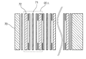
- an electrode membrane (MEA: Membrane-Electrode Assembly), which is a main component, is located at the innermost side, and the electrode membrane 71 includes a solid polymer electrolyte membrane capable of moving hydrogen cations. And a catalyst layer coated on both surfaces of the electrolyte membrane such that hydrogen and oxygen can react, that is, a cathode and an anode.
- a gas diffusion layer (GDL), a gasket, and the like are stacked on an outer portion of the electrode layer 71, that is, on an outer portion where the cathode and the anode are located, and fuel is provided on the outer side of the gas diffusion layer 72.
- GDL gas diffusion layer
- a gasket and the like are stacked on an outer portion of the electrode layer 71, that is, on an outer portion where the cathode and the anode are located, and fuel is provided on the outer side of the gas diffusion layer 72.
- Separator formed with a flow field is formed to supply and discharge the water generated by the reaction, the outer end is coupled to the metal end plate 70 for supporting each of the above components .
- oxidation of hydrogen proceeds to generate hydrogen ions (Proton) and electrons (Electron), and the generated hydrogen ions and electrons are moved to the cathode through the electrolyte membrane and the separator, respectively.
- the cathode generates water through an electrochemical reaction involving hydrogen ions, electrons, and oxygen in the air, which are moved from the anode, and generates electrical energy from the flow of electrons.
- the end plate functions to support the respective components so that even surface pressure is maintained in the stack. Maintaining the even surface pressure is related to preventing leakage of fluid in the stack and reducing electrical contact resistance between cells. This is an important factor in determining stack performance.
- Conventional end plate fastening method adopts a method of fastening the end plate 100 disposed on both ends using a long bolt 110, which is a long wire screw as shown in the accompanying FIG. Since the end plate 100 is a plastic material, the metal reinforcement 120 is added to the uniform distribution of pressure.
- the first intake port 101, the second intake port 102, and the exhaust port 103 are made of a screw thread so that the connector b is fastened, connected to the connector b, and then integrated. Thereafter, the first intake port 101, the second intake port 102, and the exhaust port 103 are connected to pipes using a quick fastener (a).
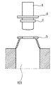
- FIG. 2 is a cross-sectional view showing a structure in which a quick fastener (a) is connected to a conventional exhaust port.
- the exhaust port 103 of the end plate 100 is fixed by a screw thread to insert a quick fastener having an O-ring gasket (c) in the connector (b) integrated.
- the metal reinforcing member 120 is manufactured by machining, additional processing cost is generated, and the weight of the end plate 100 is increased to increase the weight of the entire stack.
- the end plate 100 adopts a thread processing method through machining, there is a problem that the manufacturing cost is increased and, in general, it takes time for mounting the six connectors (b) and is not suitable for mass production. .
- the present invention has been made to solve the problems of the prior art as described above, an object of the present invention, in particular, by forming a predetermined groove on the outer surface of the end plate so that the surface pressure is uniformly distributed, fastening of the quick fastener It is to provide an end plate for a fuel cell stack to facilitate the uniformity of the clamping pressure.
- the outer surface of the end plate is formed with a recess of a predetermined area in the center so that the surface pressure is uniformly distributed during thermal deformation.
- a hole is formed around the groove, and after the pipe is connected using the quick fastener, a plurality of quick fasteners are fixed to the end plate by fasteners.
- the fastener is formed with a flow path hole in the center so that the quick fastener protrudes, and both ends of the fastener are fastened to the rear surface of the end plate.
- the hole is inserted into the bottom of the quick fastener.
- the groove having a predetermined area formed on the outer surface of the end plate does not incur a cost due to the processing of the metal reinforcement, and has an effect of preventing the weight increase of the stack due to the metal reinforcement.
- the connector is manufactured and not molded due to the fastener, so that the work is time-saving and efficient assembly is effective for mass production.
- FIG. 1 is an exemplary view showing a fastening method of an end plate for a conventional fuel cell stack.
- FIG. 2 is a cross-sectional view showing a structure in which a quick fastener (a) is connected to a conventional exhaust port.
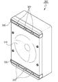
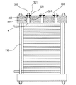
- Figure 3 is a front perspective view for showing the fuel cell stack end plate according to an embodiment of the present invention.
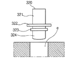
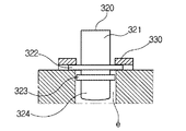
- Figure 4 is a cross-sectional view showing that the quick fastener 320 according to an embodiment of the present invention is inserted into the flow path, fixed by the fastener 330.
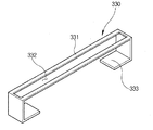
- FIG 5 is an exemplary view showing a plurality of quick fasteners 320 are fixed by the fastener 330 according to an embodiment of the present invention.
- Figure 6 is a cross-sectional view showing a cross section of the fuel cell stack end plate according to an embodiment of the present invention.
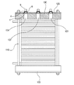
- FIG. 7 is a cross-sectional view showing each configuration of a fuel cell stack.
- FIG 3 is a front perspective view illustrating an end plate for a fuel cell stack according to an exemplary embodiment of the present invention.
- a groove 310 having a predetermined area is recessed in a central portion such that the surface pressure is uniformly distributed during thermal deformation.
- Holes for inserting a plurality of quick fasteners 320 are formed in the outer surface of the groove 310 formed as described above, and after the pipes are connected using the quick fasteners 320, two fasteners 330 are formed. Is used to secure the plurality of quick fasteners 320 to the endplate 300.
- Each fastener 330 is formed in the center of the flow path hole so that the quick fastener 320 protrudes, both ends of the fastener 330 is formed to be caught on the back of the end plate.
- the fastener 330 may fix the plurality of quick fasteners 320 arranged in a straight shape on the end plate 300.
- FIG. 4 is a cross-sectional view showing that the quick fastener 320 according to an embodiment of the present invention is inserted into the flow path and fixed by the fastener 330.
- the quick fastener 320 is inserted into the flow path (e) formed for the inlet or exhaust port. At this time, since the sealing portion 322 of the quick fastener 320 is larger in diameter than the flow path e, only the lower end of the sealing portion 322 is inserted.
- the end plate 300 does not include the connector b for connection with the quick fastener 320.
- the quick fastener 320 when the quick fastener 320 is inserted into the end plate 300, the quick fastener 320 is fixed using the fastener 330.
- the fastener 330 is fastened in a state where the quick fastener 320 is inserted.
- the fastener 330 is fastened after all of the quick fasteners 320 provided in the three intake and exhaust holes are inserted, with reference to FIG. 4 (b).
- the fastener 330 is formed with a flow path hole so that the upper fastener 321 of the quick fastener 320 protrudes. Accordingly, the fastener 330 protrudes the upper fastener 321 to the upper end of the end plate 300 and compresses and covers the seal 322 of the quick fastener 320 so that the quick fastener 320 is positioned on the end plate 300. It is fastened to be fixed to.
- the quick fastener 320 inserted and fixed by the fastener 330 is fixed in the state where only the upper fastener 321 protrudes, and gas is leaked to the outside by the sealing part 322 and the O-ring gasket 323. This can prevent the situation.
- FIG 5 is an exemplary view showing that a plurality of quick fasteners 320 are fixed by the clamp 330 according to an embodiment of the present invention.
- the fastener 330 has a sealing portion 322 of the quick fastener 320 positioned at the top of the end plate 300 at left and right sides of the passage hole 332.
- the fixing part 331 is fixed.
- both ends of the clamp 330 is provided with a latch portion 333 to be fixed to the rear surface of the end plate (300).
- FIG. 6 is a cross-sectional view illustrating a cross section of an end plate for a fuel cell stack according to an exemplary embodiment of the present invention.
- Fastening method of the end plate 300 for a fuel cell stack is a long bolt 110 is a long wire screw end plate 300 disposed at both ends as shown in FIG. Adopt the method of tightening.
- the end plate 300 has a groove 310 having a predetermined area in the center portion as shown in FIG. 3 so that the surface pressure is uniformly distributed during thermal deformation for uniform distribution of pressure.
- the lower end of the sealing portion 322 of the quick fastener 320 is inserted into the plurality of flow paths e so that the sealing portion 322 and the upper fastener 321 protrude.
- the fixing part 331 of the fixing clamp 330 is fixed by pressing both ends of the sealing part 322 while the latching parts 333 formed at both ends of the fixing clamp 330 are caught on the rear surface of the end plate 300. 330).
- the end plate 300 can remove the metal reinforcement by the groove having a predetermined area formed on the outer surface.
- end plate 300 is advantageous for mass production by removing a plurality of connectors provided in advance due to the fastener 330.
Landscapes
- Life Sciences & Earth Sciences (AREA)
- Engineering & Computer Science (AREA)
- Manufacturing & Machinery (AREA)
- Sustainable Development (AREA)
- Sustainable Energy (AREA)
- Chemical & Material Sciences (AREA)
- Chemical Kinetics & Catalysis (AREA)
- Electrochemistry (AREA)
- General Chemical & Material Sciences (AREA)
- Fuel Cell (AREA)
Description
본 발명은 연료전지 스택용 엔드플레이트에 관한 것으로서 더욱 상세하게는 열변형시 면압이 균일하게 분포되도록 엔드플레이트 외부면의 중앙부에 소정 면적의 홈이 함몰 형성하고, 홈의 외부면 주위에 홀(hole)을 성형하며, 퀵 패스너를 이용하여 배관이 연결된 후, 고정쇠가 사용되어 다수의 퀵 패스너를 엔드플레이트에 고정하는 연료전지 스택용 엔드플레이트에 관한 것이다.
고분자 전해질 연료전지(Polyer Electrolyte Membrane Fuel Cells)는 수소와 산소를 전기화학적으로 반응시켜 물을 생성하면서 전기를 발생시키는 장치로서, 다른 형태의 연료전지에 비해 효율이 높고, 전류밀도 및 출력밀도가 크며, 또한 시동 시간이 짧고 부하 변화에 빠른 응답 특성을 갖는 장점으로 인하여, 무공해 차량의 동력원, 자가 발전용, 이동용 및 군사용 전원 등 다양한 분야에 응용될 수 있다.
첨부한 도 7을 참고로 연료전지 스택의 각 구성을 간략하게 살펴보면 다음과 같다.
상기 연료전지 스택에서, 가장 안쪽에 주요 구성 부품인 전극막(MEA: Membrane-Electrode Assembly)이 위치하는데, 이 전극막(71)은 수소 양이온(Proton)을 이동시켜 줄 수 있는 고체 고분자 전해질막과, 이 전해질막 양면에 수소와 산소가 반응할 수 있도록 도포된 촉매층, 즉 캐소드 및 애노드로 구성되어 있다.
또한, 상기 전극막(71)의 바깥 부분, 즉 캐소드 및 애노드가 위치한 바깥 부분에 가스확산층(GDL: Gas Diffusion Layer), 가스켓 등이 적층되며 위치하고, 상기 가스확산층(72)의 바깥 쪽에는 연료를 공급하고 반응에 의해 발생된 물을 배출하도록 유로(Flow Field)가 형성된 분리판(Separator)이 위치하며, 가장 바깥쪽에는 상기한 각 구성들을 지지하기 위한 금속재질의 엔드플레이트(70)가 결합된다.
따라서, 연료전지의 애노드에서는 수소의 산화반응이 진행되어 수소이온(Proton)과 전자(Electron)가 발생하며, 이때 생성된 수소이온과 전자는 각각 전해질막과 분리판을 통하여 캐소드극으로 이동하게 된다.
이때, 캐소드극에서는 애노드극으로부터 이동한 수소이온과 전자, 공기중의 산소가 참여하는 전기화학반응을 통하여 물을 생성하며, 이러한 전자의 흐름으로부터 전기에너지를 생성하게 된다.
이러한 연료전지 스택에 있어서, 엔드플레이트는 스택내에서 고른 면압이 유지되도록 각 구성들을 지지하는 기능을 하는 바, 고른 면압을 유지하는 것은 스택내 유체의 누설 방지, 셀간 전기 접촉저항의 감소와 관련하여 스택 성능을 좌우하는 중요한 인자이다.
기존의 엔드플레이트 체결 방식은 첨부한 도 1에 도시된 바와 같이 양단부에 배치된 엔드플레이트(100)를 긴 전선나사인 장볼트(110)를 이용하여 체결하는 방식을 채택한다. 여기서 엔드플레이트(100)는 플라스틱 재질이기 때문에 압력의 균일한 분포를 위해서 금속 보강재(120)을 추가한다. 그리고 제1 흡기구(101), 제2 흡기구(102), 및 배기구(103)는 커넥터(b)가 체결되도록 나사선을 만들어 커넥터(b)와 연결한 후 일체화 시킨다. 그 후 제1 흡기구(101), 제2 흡기구(102), 및 배기구(103)는 퀵 패스너(Quick Fastner)(a)가 이용되어 배관이 연결한다.
도 2는 종래의 배기구에 퀵 패스너(a)가 연결되는 구조를 보여주는 단면도이다.
도 2(a)를 참조하면, 엔드플레이트(100)의 배기구(103)가 나사선에 의해 고정되어 일체화된 커넥터(b)에 O링 게스킷(c)을 구비하는 퀵 패스너를 삽입한다.
종래에는 금속 보강재(120)를 기계 가공하여 제작하기 때문에 추가 가공비용이 발생하고, 엔드플레이트(100)의 중량이 증가하여 스택 전체의 중량이 증가한다는 문제점이 있었다.
또한, 엔드플레이트(100)에 기계 가공을 통한 나사선 가공방식을 채택하면 제작비용의 증가는 물론, 일반적으로 6개의 커넥터(b)를 장착하는 작업에 시간이 소요되어 대량생산에 부적합하다는 문제점도 있었다.
그리고 각각의 흡기구(101, 102)와 배기구(103)에 퀵 패스너를 사용하는 경우 커넥터(b) 연결에 필요한 작업시간을 절감할 수는 있지만, 커넥터(b)의 돌출에 의해 파손에 취약하고 커넥터(b)와 일체형으로 성형되기 때문에 커넥터(b) 한 개의 파손일지라도 엔드플레이트(100) 전체를 교체해야 한다는 문제점이 있었다.
이에, 연료전지 스택용 엔드플레이트에 추가되는 금속 보강재(120)를 제거하고, 커넥터(b)의 연결을 용이하게 하며, 체결압력의 균일한 유지로 인한 파손을 미연에 방지하는 방안이 요구된다.
본 발명은 상술한 바와 같은 종래기술의 문제점을 해결하기 위해 안출된 것으로서, 본 발명의 목적은, 특히 엔드플레이트의 외부면에 소정의 홈을 성형하여 면압이 균일하게 분포되도록 하고, 퀵 패스너의 체결을 용이하게 하여 체결압력의 균일한 유지가 가능한 위한 연료전지 스택용 엔드플레이트를 제공하는 것이다.
이를 위해 본 발명에 따르는 연료전지 스택용 엔드플레이트는, 엔드플레이트의 외부면은 열변형시 면압이 균일하게 분포되도록 중앙부에 소정 면적의 홈이 함몰 형성된다.
홈은 주위에 홀(hole)이 성형되고, 퀵 패스너를 이용하여 배관이 연결된 후, 고정쇠에 의해 다수의 퀵 패스너가 엔드플레이트에 고정된다.
고정쇠는 퀵 패스너가 돌출하도록 중앙에 유로 홀이 형성되며, 고정쇠의 양단은 엔드플레이트의 배면에 걸리도록 형성된다.
홀(hole)은 퀵 패스너의 하단이 삽입된다.
본 발명에 따르면 엔드플레이트의 외부면에 형성되는 소정의 면적을 갖는 홈에 의해 금속 보강재의 가공으로 인한 비용이 발생하지 않고, 금속 보강재로 인한 스택의 무게증가를 방지하는 효과가 있다.
또한, 본 발명에 따르면 고정쇠로 인해 커넥터를 제조하고 성형하지 않기 때문에 작업에 시간이 절감되고 효율적인 조립으로 인해 대량생산에 효율적이라는 효과도 있다.
도 1은 종래의 연료전지 스택용 엔드플레이트의 체결방식을 보여주는 예시도.
도 2는 종래의 배기구에 퀵 패스너(a)가 연결되는 구조를 보여주는 단면도.
도 3은 본 발명의 일 실시 예에 따르는 연료전지 스택용 엔드플레이트를 보여주기 위한 정면 사시도.
도 4는 본 발명의 일 실시 예에 따르는 퀵 패스너(320)가 유로에 삽입되어, 고정쇠(330)에 의해 고정되는 것을 보여주는 단면도.
도 5는 본 발명의 일 실시 예에 따르는 고정쇠(330)에 의해 다수의 퀵 패스너(320)가 고정되는 것을 보여주는 예시도.
도 6은 본 발명의 일 실시 예에 따르는 연료전지 스택용 엔드플레이트의 단면을 보여주는 단면도.
도 7은 연료전지 스택의 각 구성을 보여주는 단면도.
이하에서는 첨부된 도면들을 참조하여 본 발명의 실시 예에 따른 연료전지 스택용 엔드플레이트를 상세히 설명한다.
도 3 내지 도 6의 동일 부재에 대해서는 동일한 도면 번호를 기재하였다.
아울러, 본 발명을 설명함에 있어서, 관련된 공지 기능 혹은 구성에 대한 구체적인 설명이 본 발명의 요지를 불필요하게 흐릴 수 있다고 판단된 경우 그 상세한 설명은 생략한다.
도 3은 본 발명의 일 실시 예에 따르는 연료전지 스택용 엔드플레이트를 보여주기 위한 정면 사시도이다.
본 발명에 따르는 연료전지 스택용 엔드플레이트(300)는 열변형시 면압이 균일하게 분포되도록 중앙부에 소정 면적을 갖는 홈(310)이 함몰 형성된다.
이와 같이 형성되는 홈(310)의 외부면에는 다수의 퀵 패스너(320)가 삽입되기 위한 홀(hole)이 형성되고, 퀵 패스너(320)를 이용하여 배관이 연결된 후, 두 개의 고정쇠(330)가 사용되어 다수의 퀵 패스너(320)를 엔드플레이트(300)에 고정시킨다.
각각의 고정쇠(330)는 퀵 패스너(320)가 돌출하도록 중앙에 유로 홀이 성형되며, 고정쇠(330)의 양단은 상기 엔드플레이트의 배면에 걸리도록 형성된다.
따라서, 고정쇠(330)는 일자 형태로 배치된 다수의 퀵 패스너(320)를 엔드플레이트(300) 상에 고정할 수 있다.
도 4는 본 발명의 일 실시 예에 따르는 퀵 패스너(320)가 유로에 삽입되어, 고정쇠(330)에 의해 고정되는 것을 보여주는 단면도이다.
도 4(a)를 참조하면, 퀵 패스너(320)는 흡기구 또는 배기구를 위해 형성된 유로(e)에 삽입된다. 이 때, 퀵 패스너(320)의 밀봉부(322)는 유로(e)보다 지름이 크기 때문에 밀봉부(322)의 하단만이 삽입된다.
이와 같이 퀵 패스너(320)가 유로(e)에 삽입됨에 따라, 엔드플레이트(300)는 퀵 패스너(320)와의 연결을 위해 커넥터(b)를 구비하지 않는다.
이 경우, 퀵 패스너(320)가 엔드플레이트(300)의 내부에 삽입되면, 고정쇠(330)를 이용하여 퀵 패스너(320)를 고정시킨다.
도 4(b)를 참조하면, 퀵 패스너(320)가 삽입된 상태에서 고정쇠(330)를 체결한다. 고정쇠(330)는 도 4(b)를 참조하여, 모두 합쳐 3개의 흡배기구에 구비된 퀵 패스너(320)가 모두 삽입된 후에 체결된다. 이 때 고정쇠(330)는 퀵 패스너(320)의 상단 패스너(321)가 돌출할 수 있도록 유로 홀이 형성되어 있다. 따라서 고정쇠(330)는 상단 패스너(321)를 엔드플레이트(300)의 상단에 돌출시키고 퀵 패스너(320)의 밀봉부(322)를 압착하여 덮음으로써 퀵 패스너(320)가 엔드플레이트(300) 상에 고정되도록 체결된다. 그러면 밀봉부(322)의 하단에 구비된 O링 게스킷(323)과 하단 패스너(324)가 모두 엔드플레이트(300)의 내부에 삽입된 채로 고정된다. 이때 고정쇠(330)의 양단은 엔드플레이트(300)의 배면에 걸려 고정되는 걸쇠형태로 형성된다.
이와 같이 고정쇠(330)에 의해 삽입 고정된 퀵 패스너(320)는 상단 패스너(321)만 돌출된 상태에서 고정되고, 밀봉부(322)와 O링 게스킷(323)에 의해 가스가 외부로 유출되는 상황을 방지할 수 있다.
도 5는 본 발명의 일 실시 예에 따르는 고정쇠(330)에 의해 다수의 퀵 패스너(320)가 고정되는 것을 보여주는 예시도이다.
도 5를 참조하면, 본 발명의 일 실시 예에 따르는 고정쇠(330)는 엔드플레이트(300)의 상단에 위치하는 퀵 패스너(320)의 밀봉부(322)를 유로홀(332)의 좌우에 형성된 고정부(331)로 고정한다. 이 때 고정쇠(330)의 양단은 엔드플레이트(300)의 배면에 걸려 고정시킬 수 있도록 걸쇠부(333)를 구비한다.
도 6은 본 발명의 일 실시 예에 따르는 연료전지 스택용 엔드플레이트의 단면을 보여주는 단면도이다.
본 발명의 일 실시 예에 따르는 연료전지 스택용 엔드플레이트(300)의 체결 방식은 첨부한 도 6에 도시된 바와 같이 양단부에 배치된 엔드플레이트(300)를 긴 전선나사인 장볼트(110)를 이용하여 체결하는 방식을 채택한다. 여기서 엔드플레이트(300)는 압력의 균일 분포를 위해서 열변형시 면압이 균일하게 분포되도록 도 3에 도시한 바와 같이 중앙부에 소정 면적을 갖는 홈(310)이 형성되어 있다.
다수의 유로(e)에는 각각의 퀵 패스너(320)의 밀봉부(322) 하단이 삽입되어 밀봉부(322)와 상단 패스너(321)가 돌출한다. 이때 고정쇠(330)의 고정부(331)는 밀봉부(322)의 양단을 압착하여 고정하면서 고정쇠(330)의 양단에 형성된 걸쇠부(333)가 엔드플레이트(300)의 배면에 걸림으로써 고정쇠(330)를 고정한다.
따라서 본 발명의 일 실시 예에 따르는 엔드플레이트(300)는 외부면에 형성되는 소정의 면적을 갖는 홈에 의해 금속 보강재를 제거할 수 있다.
그리고, 본 발명의 일 실시 예에 따르는 엔드플레이트(300)는 고정쇠(330)로 인해 기존에 구비된 다수의 커넥터를 제거하여 대량생산에 유리하다.
이상에서는 본 발명의 바람직한 실시 예에 대하여 도시하고 설명하였지만, 본 발명은 상술한 특정의 실시 예에 한정되지 아니하며, 청구범위에서 청구하는 본 발명의 요지를 벗어남이 없이 당해 발명이 속하는 기술분야에서 통상의 지식을 가진자에 의해 다양한 변형실시가 가능한 것은 물론이고, 이러한 변형실시들은 본 발명의 기술적 사상이나 전망으로부터 개별적으로 이해되어져서는 안될 것이다.
* 부호의 설명 *
310: 홈 320: 퀵 패스너
330: 고정쇠 331: 고정부
332: 유로홀 333: 걸쇠부
Claims (4)
- 연료전지 스택용 엔드플레이트에 있어서,상기 엔드플레이트의 외부면은 열변형시 면압이 균일하게 분포되도록 중앙부에 소정 면적의 홈이 함몰 형성되는 것을 특징으로 하는 연료전지 스택용 엔드플레이트.
- 제 1항에 있어서, 상기 홈은주위에 홀(hole)이 성형되고, 퀵 패스너를 이용하여 배관이 연결된 후, 고정쇠에 의해 다수의 퀵 패스너가 엔드플레이트에 고정되는 것을 특징으로 하는 연료전지 스택용 엔드플레이트.
- 제 2항에 있어서, 상기 고정쇠는상기 퀵 패스너가 돌출하도록 중앙에 유로 홀이 형성되며, 상기 고정쇠의 양단은 상기 엔드플레이트의 배면에 걸리도록 형성되는 것을 특징으로 하는 연료전지 스택용 엔드플레이트
- 제 2항에 있어서, 상기 홀(hole)은퀵 패스너의 하단이 삽입되는 것을 특징으로 하는 연료전지 스택용 엔드플레이트.
Applications Claiming Priority (2)
| Application Number | Priority Date | Filing Date | Title |
|---|---|---|---|
| KR1020110146416A KR101357880B1 (ko) | 2011-12-29 | 2011-12-29 | 연료전지 스택용 엔드플레이트 |
| KR10-2011-0146416 | 2011-12-29 |
Publications (1)
| Publication Number | Publication Date |
|---|---|
| WO2013100670A1 true WO2013100670A1 (ko) | 2013-07-04 |
Family
ID=48698011
Family Applications (1)
| Application Number | Title | Priority Date | Filing Date |
|---|---|---|---|
| PCT/KR2012/011642 Ceased WO2013100670A1 (ko) | 2011-12-29 | 2012-12-27 | 연료전지 스택용 엔드플레이트 |
Country Status (2)
| Country | Link |
|---|---|
| KR (1) | KR101357880B1 (ko) |
| WO (1) | WO2013100670A1 (ko) |
Citations (5)
| Publication number | Priority date | Publication date | Assignee | Title |
|---|---|---|---|---|
| JP2002063930A (ja) * | 2000-08-14 | 2002-02-28 | Sony Corp | 燃料電池のスタック構造 |
| US20060194094A1 (en) * | 2003-02-23 | 2006-08-31 | Joerg Evertz | End plate for a stack of fuel cells |
| KR20090087628A (ko) * | 2008-02-13 | 2009-08-18 | 한국과학기술원 | 연료전지 스택용 엔드플레이트 및 그 제조방법 |
| KR20090110608A (ko) * | 2008-04-18 | 2009-10-22 | 한국기계연구원 | 연료전지 |
| KR20110040487A (ko) * | 2009-10-14 | 2011-04-20 | 현대자동차주식회사 | 체결장치 및 이를 포함하는 연료 전지 스택 |
-
2011
- 2011-12-29 KR KR1020110146416A patent/KR101357880B1/ko not_active Expired - Fee Related
-
2012
- 2012-12-27 WO PCT/KR2012/011642 patent/WO2013100670A1/ko not_active Ceased
Patent Citations (5)
| Publication number | Priority date | Publication date | Assignee | Title |
|---|---|---|---|---|
| JP2002063930A (ja) * | 2000-08-14 | 2002-02-28 | Sony Corp | 燃料電池のスタック構造 |
| US20060194094A1 (en) * | 2003-02-23 | 2006-08-31 | Joerg Evertz | End plate for a stack of fuel cells |
| KR20090087628A (ko) * | 2008-02-13 | 2009-08-18 | 한국과학기술원 | 연료전지 스택용 엔드플레이트 및 그 제조방법 |
| KR20090110608A (ko) * | 2008-04-18 | 2009-10-22 | 한국기계연구원 | 연료전지 |
| KR20110040487A (ko) * | 2009-10-14 | 2011-04-20 | 현대자동차주식회사 | 체결장치 및 이를 포함하는 연료 전지 스택 |
Also Published As
| Publication number | Publication date |
|---|---|
| KR101357880B1 (ko) | 2014-02-05 |
| KR20130077615A (ko) | 2013-07-09 |
Similar Documents
| Publication | Publication Date | Title |
|---|---|---|
| US10297854B2 (en) | Fuel cell stack | |
| CN111293331B (zh) | 具有加热单元的燃料电池 | |
| CA2522702C (en) | Fuel cell | |
| US20150118587A1 (en) | Fuel cell stack including dummy cell | |
| CN115101772B (zh) | 一种用于固体氧化物燃料电池电堆模组的气流分配装置 | |
| CN113793944A (zh) | 燃料电池夹具及测试装置 | |
| WO2013077488A1 (ko) | 고분자 전해질 연료전지용 분리판 및 이것을 이용한 고분자 전해질 연료전지 | |
| US7494737B2 (en) | Fuel cell having manifold apertures and cover plates | |
| KR100954432B1 (ko) | 가스켓 일체형 전류 집전체를 구비한 연료전지 스택 | |
| EP1685621B1 (en) | Multi-cell fuel layer and system | |
| CN112864410B (zh) | 一种燃料电池及燃料电池发电系统 | |
| KR100778634B1 (ko) | 연료 전지, 연료 전지용 분리판 및 이를 구비하는 연료전지 스택 | |
| WO2011090246A1 (ko) | 보조유동유로를 가지는 연료전지용 분리판 | |
| WO2018143610A1 (ko) | 연료전지 스택 | |
| WO2013100554A1 (ko) | 분기유로를 이용한 연료전지 스택 | |
| WO2013100670A1 (ko) | 연료전지 스택용 엔드플레이트 | |
| KR20210139071A (ko) | 연료전지용 엔드플레이트 | |
| WO2020209533A1 (ko) | 연료전지 스택의 분산형 체결 구조 | |
| CN217034181U (zh) | 一种燃料电池测试用进出气结构 | |
| WO2017146359A1 (ko) | 연료전지 분리판 및 이를 갖는 연료전지 스택 | |
| CN213278135U (zh) | 一种质子交换膜燃料电池流道 | |
| US11791491B2 (en) | Fuel cell | |
| KR100751881B1 (ko) | 연료전지 스택 | |
| CN117334981A (zh) | 燃料电池 | |
| EP3590144B1 (en) | Novel modular electrochemical cell and stack design |
Legal Events
| Date | Code | Title | Description |
|---|---|---|---|
| 121 | Ep: the epo has been informed by wipo that ep was designated in this application |
Ref document number: 12863453 Country of ref document: EP Kind code of ref document: A1 |
|
| NENP | Non-entry into the national phase |
Ref country code: DE |
|
| 122 | Ep: pct application non-entry in european phase |
Ref document number: 12863453 Country of ref document: EP Kind code of ref document: A1 |