WO2013100305A1 - 토네이도형 풍력발전장치 - Google Patents
토네이도형 풍력발전장치 Download PDFInfo
- Publication number
- WO2013100305A1 WO2013100305A1 PCT/KR2012/006763 KR2012006763W WO2013100305A1 WO 2013100305 A1 WO2013100305 A1 WO 2013100305A1 KR 2012006763 W KR2012006763 W KR 2012006763W WO 2013100305 A1 WO2013100305 A1 WO 2013100305A1
- Authority
- WO
- WIPO (PCT)
- Prior art keywords
- plate
- fixed
- guide
- rotating
- shaft
- Prior art date
Links
- 238000010248 power generation Methods 0.000 claims abstract description 31
- 230000006698 induction Effects 0.000 claims description 11
- 230000002093 peripheral effect Effects 0.000 claims description 5
- 238000000034 method Methods 0.000 claims description 4
- 238000004891 communication Methods 0.000 claims description 3
- 230000000149 penetrating effect Effects 0.000 claims description 3
- 230000015572 biosynthetic process Effects 0.000 claims description 2
- 230000008878 coupling Effects 0.000 claims description 2
- 238000010168 coupling process Methods 0.000 claims description 2
- 238000005859 coupling reaction Methods 0.000 claims description 2
- 230000000630 rising effect Effects 0.000 abstract description 2
- 238000004519 manufacturing process Methods 0.000 description 4
- 239000000446 fuel Substances 0.000 description 3
- 238000009434 installation Methods 0.000 description 3
- 230000004308 accommodation Effects 0.000 description 2
- 239000012530 fluid Substances 0.000 description 2
- 239000002803 fossil fuel Substances 0.000 description 2
- OKTJSMMVPCPJKN-UHFFFAOYSA-N Carbon Chemical compound [C] OKTJSMMVPCPJKN-UHFFFAOYSA-N 0.000 description 1
- 238000007664 blowing Methods 0.000 description 1
- 229910052799 carbon Inorganic materials 0.000 description 1
- 238000010276 construction Methods 0.000 description 1
- 238000001816 cooling Methods 0.000 description 1
- 235000012489 doughnuts Nutrition 0.000 description 1
- 230000000694 effects Effects 0.000 description 1
- 239000000463 material Substances 0.000 description 1
- 239000003758 nuclear fuel Substances 0.000 description 1
- 239000002699 waste material Substances 0.000 description 1
- 238000003466 welding Methods 0.000 description 1
Images


Classifications
-
- F—MECHANICAL ENGINEERING; LIGHTING; HEATING; WEAPONS; BLASTING
- F03—MACHINES OR ENGINES FOR LIQUIDS; WIND, SPRING, OR WEIGHT MOTORS; PRODUCING MECHANICAL POWER OR A REACTIVE PROPULSIVE THRUST, NOT OTHERWISE PROVIDED FOR
- F03D—WIND MOTORS
- F03D3/00—Wind motors with rotation axis substantially perpendicular to the air flow entering the rotor
- F03D3/04—Wind motors with rotation axis substantially perpendicular to the air flow entering the rotor having stationary wind-guiding means, e.g. with shrouds or channels
- F03D3/0436—Wind motors with rotation axis substantially perpendicular to the air flow entering the rotor having stationary wind-guiding means, e.g. with shrouds or channels for shielding one side of the rotor
- F03D3/0445—Wind motors with rotation axis substantially perpendicular to the air flow entering the rotor having stationary wind-guiding means, e.g. with shrouds or channels for shielding one side of the rotor the shield being fixed with respect to the wind motor
- F03D3/0463—Wind motors with rotation axis substantially perpendicular to the air flow entering the rotor having stationary wind-guiding means, e.g. with shrouds or channels for shielding one side of the rotor the shield being fixed with respect to the wind motor with converging inlets, i.e. the shield intercepting an area greater than the effective rotor area
-
- F—MECHANICAL ENGINEERING; LIGHTING; HEATING; WEAPONS; BLASTING
- F03—MACHINES OR ENGINES FOR LIQUIDS; WIND, SPRING, OR WEIGHT MOTORS; PRODUCING MECHANICAL POWER OR A REACTIVE PROPULSIVE THRUST, NOT OTHERWISE PROVIDED FOR
- F03D—WIND MOTORS
- F03D3/00—Wind motors with rotation axis substantially perpendicular to the air flow entering the rotor
- F03D3/02—Wind motors with rotation axis substantially perpendicular to the air flow entering the rotor having a plurality of rotors
-
- F—MECHANICAL ENGINEERING; LIGHTING; HEATING; WEAPONS; BLASTING
- F03—MACHINES OR ENGINES FOR LIQUIDS; WIND, SPRING, OR WEIGHT MOTORS; PRODUCING MECHANICAL POWER OR A REACTIVE PROPULSIVE THRUST, NOT OTHERWISE PROVIDED FOR
- F03D—WIND MOTORS
- F03D3/00—Wind motors with rotation axis substantially perpendicular to the air flow entering the rotor
- F03D3/04—Wind motors with rotation axis substantially perpendicular to the air flow entering the rotor having stationary wind-guiding means, e.g. with shrouds or channels
- F03D3/0427—Wind motors with rotation axis substantially perpendicular to the air flow entering the rotor having stationary wind-guiding means, e.g. with shrouds or channels with converging inlets, i.e. the guiding means intercepting an area greater than the effective rotor area
-
- F—MECHANICAL ENGINEERING; LIGHTING; HEATING; WEAPONS; BLASTING
- F03—MACHINES OR ENGINES FOR LIQUIDS; WIND, SPRING, OR WEIGHT MOTORS; PRODUCING MECHANICAL POWER OR A REACTIVE PROPULSIVE THRUST, NOT OTHERWISE PROVIDED FOR
- F03D—WIND MOTORS
- F03D9/00—Adaptations of wind motors for special use; Combinations of wind motors with apparatus driven thereby; Wind motors specially adapted for installation in particular locations
- F03D9/20—Wind motors characterised by the driven apparatus
- F03D9/25—Wind motors characterised by the driven apparatus the apparatus being an electrical generator
-
- F—MECHANICAL ENGINEERING; LIGHTING; HEATING; WEAPONS; BLASTING
- F05—INDEXING SCHEMES RELATING TO ENGINES OR PUMPS IN VARIOUS SUBCLASSES OF CLASSES F01-F04
- F05B—INDEXING SCHEME RELATING TO WIND, SPRING, WEIGHT, INERTIA OR LIKE MOTORS, TO MACHINES OR ENGINES FOR LIQUIDS COVERED BY SUBCLASSES F03B, F03D AND F03G
- F05B2240/00—Components
- F05B2240/20—Rotors
- F05B2240/21—Rotors for wind turbines
- F05B2240/211—Rotors for wind turbines with vertical axis
-
- Y—GENERAL TAGGING OF NEW TECHNOLOGICAL DEVELOPMENTS; GENERAL TAGGING OF CROSS-SECTIONAL TECHNOLOGIES SPANNING OVER SEVERAL SECTIONS OF THE IPC; TECHNICAL SUBJECTS COVERED BY FORMER USPC CROSS-REFERENCE ART COLLECTIONS [XRACs] AND DIGESTS
- Y02—TECHNOLOGIES OR APPLICATIONS FOR MITIGATION OR ADAPTATION AGAINST CLIMATE CHANGE
- Y02B—CLIMATE CHANGE MITIGATION TECHNOLOGIES RELATED TO BUILDINGS, e.g. HOUSING, HOUSE APPLIANCES OR RELATED END-USER APPLICATIONS
- Y02B10/00—Integration of renewable energy sources in buildings
- Y02B10/30—Wind power
-
- Y—GENERAL TAGGING OF NEW TECHNOLOGICAL DEVELOPMENTS; GENERAL TAGGING OF CROSS-SECTIONAL TECHNOLOGIES SPANNING OVER SEVERAL SECTIONS OF THE IPC; TECHNICAL SUBJECTS COVERED BY FORMER USPC CROSS-REFERENCE ART COLLECTIONS [XRACs] AND DIGESTS
- Y02—TECHNOLOGIES OR APPLICATIONS FOR MITIGATION OR ADAPTATION AGAINST CLIMATE CHANGE
- Y02E—REDUCTION OF GREENHOUSE GAS [GHG] EMISSIONS, RELATED TO ENERGY GENERATION, TRANSMISSION OR DISTRIBUTION
- Y02E10/00—Energy generation through renewable energy sources
- Y02E10/70—Wind energy
- Y02E10/74—Wind turbines with rotation axis perpendicular to the wind direction
-
- Y—GENERAL TAGGING OF NEW TECHNOLOGICAL DEVELOPMENTS; GENERAL TAGGING OF CROSS-SECTIONAL TECHNOLOGIES SPANNING OVER SEVERAL SECTIONS OF THE IPC; TECHNICAL SUBJECTS COVERED BY FORMER USPC CROSS-REFERENCE ART COLLECTIONS [XRACs] AND DIGESTS
- Y02—TECHNOLOGIES OR APPLICATIONS FOR MITIGATION OR ADAPTATION AGAINST CLIMATE CHANGE
- Y02E—REDUCTION OF GREENHOUSE GAS [GHG] EMISSIONS, RELATED TO ENERGY GENERATION, TRANSMISSION OR DISTRIBUTION
- Y02E70/00—Other energy conversion or management systems reducing GHG emissions
- Y02E70/30—Systems combining energy storage with energy generation of non-fossil origin
Definitions
- the present invention relates to a tornado-type wind turbine, and more particularly, the central blade is rotated by the wind pressure rising while the wind flowing into the main body from the top, the bottom, and the bottom, respectively, causes the whirlwind on the outer circumference.
- the central blade is rotated by the wind pressure rising while the wind flowing into the main body from the top, the bottom, and the bottom, respectively, causes the whirlwind on the outer circumference.
- wind power generation is the next generation pollution-free resource that consumes no fuel because the natural resource is wind.
- wind power generation has a limitation in that it must be installed in a location where the amount of wind is particularly high in order to obtain a sufficient amount of wind power required for power generation.
- the wind power generation unit itself is very large and the amount of power generated by this unit is not so large, there is a difficulty that requires a very large area to install the wind power generation facilities.
- the present invention is to solve the above problems, the present invention allows the wind to be sucked through the bottom while allowing the wind to flow from the bottom and top of the outer circumference at the same time, so that the turbo function by the whirlwind flow inside, even by a small amount of wind
- the main purpose is to provide a wind power generator that can exhibit a strong power generation efficiency while having a.
- the present invention can produce a sufficient amount of power generation as the size that can be installed by the rooftop or factory self-generation system of the city buildings or apartments, so that the wind power generator that is easier to construct and install without being limited to the installation site or area There is another purpose to provide.
- the present invention has yet another object to provide a wind power generator having a very economical energy production efficiency because it is possible to produce a sufficient amount of power generation at a low cost.
- the wind power generator of the present invention allows the generator accommodation port to be seated at the center of the upper surface of the support plate provided at the upper portion of the support frame provided at a predetermined height, and along a predetermined radius to the outside of the generator accommodation port.
- a plurality of poles to be provided as a constant height, the upper end of the poles and the support portion is fixed to the fixing plate;
- the tubular connector is connected to be integrally connected so as to extend downward, the lower end of the connecting tube is coupled to the internal gear, the inner peripheral surface of the internal gear of the drive gear for fixing the drive gear to be engaged with the internal gear
- the inclined upper surface of the rotating plate is provided with a plurality of guide plates for guiding the lower portion to be spaced apart by a predetermined angle so that the wind flows upward from the outside, the upper surface of the guide plate ring-shaped cover plate
- One end is connected in communication with the other end to form a lower guide hole for extending the outer diameter to the outside, the upper surface of the lower body is joined to the plate forming a guide sphere of a predetermined pitch to one side of the plate surface, the plate
- the first rotating shaft which is fixed to the first and second shaft upper body fixed to the bottom surface and the center of the upper surface of the rotary plate, respectively, is coupled to the lower generator to the lower end is received and fixed to the generator receiving port, the lower
- the first rotation shaft in the body may be rotated horizontally by the outside air introduced through the lower intake portion and the lower guide hole.
- a first power generation unit configured to axially fix the upper rotating blade to be locked;
- the lower end of the upper body having the same cylindrical shape as the lower body and the guide groove in a spiral shape of a constant pitch extending to the guide groove of the lower body to the outside of the main surface to be seated and fixed to the top of the diaphragm, the upper
- the lower end of the body is connected to the guide groove so that one end is connected to the other end to form an upper guide hole for extending the outer diameter to the outside, the upper open upper portion of the upper body to be covered by the coupling of the cap plate while the upper portion
- An exhaust port is formed at one side of the main surface, and a second rotating shaft configured to simultaneously be fixed to the third and fourth shaft upper bodies fixed to the bottom of the cap plate and the center of the upper surface of the diaphragm, respectively, has an upper end of the cap plate.
- the connecting tube of the rotating part has a diameter smaller than that of the rail groove of the fixed plate, while vertically penetrating the fixed plate so that the direction of the lower guide hole and the upper guide hole is changed along the rail groove of the fixed plate. desirable.
- the diaphragm of the present invention is to be made of a laminated structure of two plates, the lower and upper rotary blades are formed with a plurality of wings radially around the axis fixing portion through which the first and second rotation shafts respectively, The outer ends of the wings are close to the inner circumferential surface of the lower body and the upper body, and each wing is to be provided to rotate only in one direction by the outside air wind flowing through the lower intake and lower guide port and the upper guide port. desirable.
- the present invention generates energy through environmentally friendly natural wind, and not only makes a significant contribution to the recent reduction of carbon emissions, but also makes it possible to eco-friendly replace a large proportion of future production energy.
- the energy production according to the present invention can minimize the cost required for energy production, thereby providing an advantage of significantly reducing the energy use burden.
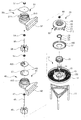
- FIG. 1 is an exploded perspective view showing an embodiment of a wind power generator according to the present invention
- FIG. 2 is a perspective view of the combined wind power generator according to the present invention
- FIG. 3 is a side cross-sectional view of FIG.
- FIG. 4 is a side view showing an inflow path of wind according to the present invention.
- FIG. 5 is a front view illustrating a state in which wind is eccentrically introduced into the lower body and the upper body through the lower guide hole and the upper guide hole according to the present invention
- FIG. 6 is a cross-sectional view taken along the line A-A of FIG.
- FIG. 7 is a cross-sectional view taken along line B-B of FIG.
- FIG. 9 is a plan view of a wind turbine generator according to the present invention.
- fixing part 11 supporting frame
- pole pole 16 fixed plate
- FIG. 1 is an exploded perspective view showing an embodiment of a wind turbine according to the present invention
- Figure 2 is a combined perspective view of the wind turbine according to the present invention
- Figure 3 is a side cross-sectional view of FIG.
- the present invention comprises a fixed part 10, a rotating part 20, a lower intake part 30, a first power generating part 40, and a second power generating part 50.
- the fixing part 10 of the present invention is composed of a combination of the support frame 11 and the support plate 12 and the generator receiving port 13, the lower generator 14, the pole pole 15, and the fixing plate 16.
- the support frame 11 is composed of a combination of a plurality of vertical pedestals having a predetermined height at a predetermined interval and horizontal holders for fixing these vertical pedestals interconnected at the top.
- Such support frame 11 is provided to support the present invention from the ground to a height raised to a certain height.
- the support plate 12 is a plate-like configuration to be seated and fixed to the upper portion of the support frame 11, the plurality of holes 120 to be vertically penetrated to the plate surface to be formed at a predetermined interval so that the wind can be introduced from the bottom More preferred.
- Generator receiver 13 is a generator protection configuration to be fixed to the center of the support plate 12 while the generator 14 is fixed to the inside to be protected from the outside.
- the pole pole 15 of the fixed portion 10 is configured as a rod or tube made of a predetermined height, the height of the upper end of the pole pole 15 is located above the height of the generator receiver 13, the generator receiver 13 A plurality of configurations to be provided uniformly at regular intervals on the concentric circles from the outside of).
- the fixing plate 16 is a configuration of a flat bottom is fixed on the top of the plurality of poles 15, so that the fixing plate 16 is formed to have a larger outer diameter than the diameter of the poles (15).
- the rotating part 20 of the present invention is composed of a rotating plate 21, the connecting pipe 22 and the internal gear 23, the drive gear 24 and the drive motor 25.
- the rotating plate 21 is configured to be rotatable in the upper portion of the fixing plate 16, the bottom surface is provided with a plurality of wheels 210 at regular intervals in a predetermined radius, these wheels 210 are fixed plate 16 It is provided to enable the rotational movement along the circular rail groove 160 formed on the upper surface of the).
- the rotating plate 21 is formed so that the upper surface is inclined upward at an angle from the outer end to the center, the position of the wheels 210 provided at a predetermined radius on the bottom of the rotating plate 21 is provided with a plurality of wheels 210 Rather than extending a certain height in a small radius rather than the tubular connector 22 is integrally connected.
- the fixing plate 16 provided below the rotating plate 21 is most preferably formed such that the plate surface penetrates downward so that the connecting pipe 22 vertically penetrates with a larger diameter than the connecting pipe 22.
- the internal gear 23 is to be coupled to the lower end of the connection pipe 22, and at one side of the internal gear 23 to be provided with a drive gear 24 to be engaged with the internal gear 23 on the inner peripheral surface of the drive at this time
- the gear 24 is fixed to the front end of the drive shaft 250 of the drive motor 25 fixedly coupled to the generator receiving port (13).
- the drive plate 24 can be rotated at an angle required by the rotating plate 21 by driving the drive gear 24.
- the drive gear 24 is automatically or manually driven by a signal transmitted according to the wind blowing direction. Be sure to
- the drive gear 24 may be driven in one direction, but it is more preferable to be driven in both directions.
- Lower intake portion 30 of the present invention is composed of a combination of the plurality of guide plates 31 and the ring-shaped cover plate 32, the plurality of guide plates 31 so that the plate surface is bent at a certain curvature
- the guide plate 31 is provided in a shape that is vertically erected at a predetermined height, such that the guide plate 31 is bonded to each other along the inclined top surface of the rotary plate 21 while the guide plate 31 between the predetermined angled configuration To be equipped.
- each guide plate 31 is formed only up to a predetermined diameter in the center, and these guide plates 31 allow the ring-shaped cover plate 32 to be integrally coupled to the top surface.
- the guide plates 31 are formed such that the upper end portion is inclined at an angle from the outer end portion to the inner end portion like the lower end portion, and the ring-shaped cover plate 32 is integrally coupled to the upper end portions of the guide plates 31.
- the outer end of the cover plate 32 is coupled to the same position as the outer end of the guide plate 31, the inner end is most preferably formed to be shorter than the guide plate (31).
- the first power generation unit 40 of the present invention is configured to combine the cylindrical lower body 41 and the diaphragm 43, the second shaft upper body 44, the first rotating shaft 45 and the lower rotating blade 46. .
- the lower body 41 of the first power generation unit 40 is configured to have a cylindrical shape with a predetermined height, such that the main surface of the lower body 41 is protruded outward so that the guide groove 410 is inwardly spiral in a predetermined pitch. To be shaped.
- the lower end of the lower body 41 is seated and fixed to the ring-shaped cover plate 32, the other end is to be connected to the guide groove 410 to the lower end side main surface so as to communicate with the other end to expand the outer diameter to the outside Induction port 42 is formed.
- the lower guide hole 42 is formed so that the other end of the inlet is formed so that the center is located on the same horizontal line as the center of the lower body 41, the lower body 41 is formed at the eccentric position from the inlet to one side
- the one end is connected to the guide groove 410 of the wind flows through the lower guide port 42 so as to flow upward along the guide groove 410 of the lower body 41 in the spiral direction.
- the lower guide hole 42 extends the inner diameter of the inlet end portion to a width close to the diameter of the lower body 41, and the wind pressure of the wind guided into the inside while the inner diameter from the inlet to the guide groove 410 side is greatly reduced. To increase gradually.
- the diaphragm 43 of the first power generation unit 40 is configured to cover the upper end of the lower body 41 which is open upward, and forms a top surface of the lower body 41 while the plate surface of the lower body 41
- the flat plate is formed in the guide groove 430 of a constant pitch to communicate with the guide groove 410, the plate surface vertically penetrates along the pitch of the guide groove 410 and at the same time allow the wind to flow along the guide groove 410. It is the composition.
- the diaphragm 43 is most preferably such that the outer diameter is made of the same size and shape as the upper end of the lower body 41, this diaphragm 43 may be made of one flat plate, as shown in the figure 2 It can also be provided with the structure which laminated
- the plates are bolted and fastened along the periphery, and the lower plate may be firmly connected to the upper end of the lower body 41 by welding or the like. Most preferred.
- the shaft portion (33, 44, 47) is a configuration that is formed in a donut shape of a predetermined diameter connected to the upper portion to communicate with each other, as seen through the enlarged view of Figure 3, the fluid (L) at a predetermined height on the outer peripheral side Is to be filled, the fluid (L) is provided with a float (F), the float (F) is configured so that the upper end is integrally connected.
- the shafts are fixed to the center of the rotating plate 21 together with the bottom of the upper plate 43 of the lower body 41, and each of the shafts 33 and 44 is perpendicular to the lower generator 14. To be located on the concentric circle.
- both ends of the first rotating shaft 45 are axially coupled to the lower generator 14 by penetrating the first shaft upper body 33 on the rotating plate 21 together with the second shaft upper body 44 on the diaphragm 43 side.
- the first shaft 45 is axially fixed to the connecting plate P between the mouth portions F of the diaphragm 43 and penetrates through the first shaft upper body 33 on the rotating plate 21 side.
- the lower end portion of the first rotary shaft 45 is to be fixed to the lower generator 14 already accommodated in the generator receiving port 13 to be fixed to the shaft connecting plate (P) of 33.
- the lower rotating blade 46 is fixed to the first rotating shaft 45 in the lower body 41, and the lower rotating blade 46 is centered on the shaft fixing portion through which the first rotating shaft 45 penetrates.
- a plurality of wings are formed radially, the wings at this time are formed so that the outer end is formed to a length close to the inner peripheral surface of the lower body 41, each wing is through the lower intake portion 30 and the lower guide port 42
- the first rotating shaft 45 is rotated while being strongly horizontally rotated by the incoming air wind.
- the second power generation unit 50 includes an upper body 51, an upper guide hole 52, a cap plate 53, a fourth shaft upper body 54, a second rotating shaft 55, an upper rotating blade 56, and an upper portion. It is a structure comprised as the generator 57.
- the upper body 51 is configured in the same cylindrical shape as the lower body 41, the main surface of the upper body 51 to protrude to the outside so that the guide groove 510 is formed in a spiral of a predetermined pitch inward. .
- the guide groove 510 of the upper body 51 is made of a configuration that is continuously connected to the guide sphere 430 formed in the diaphragm 43 from the guide groove 410 of the lower body 41.
- the upper body 51 is fixed to the lower end is seated on the upper end of the diaphragm 43, the upper guide hole 52 so that one end is in communication with the guide groove 510 on one side of the lower end side of the upper body 51. ) Is connected, and the other end is extended to the outside while the outer end is formed side by side in the same direction and size on the same vertical line as the outer end of the lower guide port 42 described above.
- the upper guide hole 52 is also connected to the guide groove 510 at an eccentrically biased position while the end portion of the outer side is centered on the same horizontal line as the upper body 51.
- the upper end of the main surface corresponding to the lower end of the main surface forming the upper induction port 52 is opened to one side so that the exhaust port 511 is formed, the exhaust port 511 is formed in a direction corresponding to the upper induction port 52
- the cap plate 53 is coupled to the upper end of the upper body 51 to open upward of the main surface on which the exhaust port 511 is formed so as to be covered.
- the fourth shaft upper body 54 is coupled to the center of the bottom of the cap plate 53 covering the upper end of the upper body 51, and the upper surface of the cap plate 53 corresponding to the fourth shaft upper body 54. Allow the generator 57 to be fixed.
- An upper rotary blade 56 having the same shape and size as the lower rotary blade 46 provided in the first power generating unit 40 is axially coupled to the second rotary shaft 55 arranged in the upper body 51.
- the upper rotary blade 56 provided inside the upper body 51 rotates with the wind introduced from the side through the upper guide hole 52 together with the wind flowing through the guide hole 430 of the diaphragm 43. Do it.
- Figure 4 is a side view showing the inflow path of the wind according to the present invention
- Figure 5 is a front view showing a state in which the wind is eccentrically introduced into the lower body and the upper body through the lower guide port and the upper guide port according to the present invention.
- 6 is a cross-sectional view taken along line AA of FIG. 5
- FIG. 7 is a cross-sectional view taken along line BB of FIG. 5
- FIG. 8 is a cross-sectional view taken along line CC of FIG. 5
- FIG. 9 is a plan view of the wind power generator according to the present invention. .
- the present invention is more preferably to be installed in the same manner as the cooling tower on the roof of public buildings such as buildings or apartments.
- the inflow of outside air through the lower intake part 30 is guided between the guide plates 31 from the outside, and is led to the side of the center on the inclined upward slope of the rotating plate 21.
- the lower body 41 of the induction groove 410 inside the air at a high speed to hit the whirlwind.
- the lower rotating blades 46 fixed to the first rotating shaft 45 in the lower body 41 are rotated by the flow pressure of the air, and the first rotating shaft is rotated by the lower rotating blades 46. As the 45 rotates, power is transmitted to the lower generator 14 through the lower end of the first rotation shaft 45.
- the air flowing along the guide groove 410 of the lower body 41 is guide grooves formed in the upper body 51 on the upper side through the guide hole 430 formed in the diaphragm 43 on the upper lower body 41.
- the outside air flows into the guide groove 510 through the upper guide hole 52 formed at the lower surface of the lower surface of the upper body 51 and flows into the guide groove 510. Air flow becomes more powerful.
- the more powerful wind pressure causes the upper rotary blade 56 axially coupled to the inside of the upper body 51 to rotate, and at the same time, the second rotary shaft 55 rotates while the second rotary shaft 55 supporting the upper rotary blade 56 rotates.
- the upper generator 57 which was axially coupled above the upper body 51 of 55, is operated.
- Air flowing along the guide groove 510 of the upper body 51 is discharged through the exhaust port 511 to be formed on one main surface in the opposite direction to the upper guide port 52 of the upper end.
- the power generation in this way enables self-power generation in public buildings where the present invention is installed, and when such self-powered public buildings increase, management difficulties or power outages occur due to power shortages, even when power demand increases rapidly. You can prevent it.
Landscapes
- Engineering & Computer Science (AREA)
- Life Sciences & Earth Sciences (AREA)
- Sustainable Development (AREA)
- Sustainable Energy (AREA)
- Chemical & Material Sciences (AREA)
- Combustion & Propulsion (AREA)
- Mechanical Engineering (AREA)
- General Engineering & Computer Science (AREA)
- Power Engineering (AREA)
- Wind Motors (AREA)
Abstract
본 발명은 토네이도형 풍력발전장치에 관한 것으로서, 즉 일정 높이로 구비되는 지지부와; 상기 지지부의 상부에서 회전판의 저면으로 형성되는 연결관의 하단부에는 구동 모터에 의해 회전하는 내접 기어가 구비되는 회전부와; 상기 회전판의 상부에서 외측방으로부터 내부로 상향 외기가 유입되도록 하는 하부 흡기부와; 상기 하부 흡기부와 하부 유도구를 통해 유입되는 외기가 소용돌이 형상으로 유동하는 풍압에 의해 하부 발전기가 발전하도록 하는 제1 발전부와; 상기 제1 발전부와 상부 유도구를 통해 유입되는 외기가 소용돌이 형상으로 유동하는 풍압에 의해 상부 발전기가 발전하도록 하는 제2 발전부에 의해 공공건물의 옥상 등에서도 안정적으로 전력을 공급받을 수 있도록 하는 특징이 있다.
Description
본 발명은 토네이도형 풍력발전장치에 관한 것으로서, 보다 상세하게는 본체의 내부로 상부와 하부 및 저부로부터 각각 내부로 유입되는 바람이 외주면을 타고 회오리를 일으키면서 상승되는 풍압에 의해 중앙의 블레이드가 회전되게 하므로서 이 블레이드의 회전력에 의해 발전이 이루어지도록 하므로서 내부로 유입되는 바람의 터보 성능에 의해 발전 효율이 더욱 향상되게 하므로서 설치 장소에 구애받지 않고 도심의 공공건물에서도 자가 발전이 가능하도록 하는 토네이도형 풍력발전장치에 관한 것이다.
일반적으로 원자력이나 화력 등의 발전설비는 핵연료봉이나 화석연료를 사용하므로서 발전 효율은 대단히 높일 수 있으나 연료를 사용한 이후의 폐기물 처리문제와 함께 화석연료의 유한성 때문에 이를 대체할 수 있는 발전 방식이 매우 활발하게 연구되고 있다.
특히 최근 불거지고 있는 원자력 발전소의 안전 문제가 전세계적으로 이슈화되면서 발전설비의 친환경적인 연료 사용이 매우 심각하게 검토되고 있다.
이러한 친환경 발전설비 중 풍력발전은 연료가 바람인 천연 자원이므로 연료의 소모가 전혀 없는 차세대 무공해 자원이다.
다만 풍력발전은 발전에 필요한 충분한 양의 풍력을 얻기 위해서 특별히 풍량이 많은 위치에 설치해야 하는 한계가 있다.
또한 각 단위당 풍력 발전설비 자체도 그 규모가 매우 크고 이 설비에서 발전되는 발전량도 그리 크지 않아 풍력발전설비를 설치하는 데에는 대단히 큰 면적이 요구되는 어려움이 있다.
따라서 일부는 육상에 건설되고 있기는 하나 설치면적을 확보하는 어려움이 많아 최근에는 해상에 설치되도록 하는 추세이며, 다만 이러한 풍력 발전설비는 건설비가 막대하게 소요되는 비경제적인 문제가 있다.
이에 본 발명은 상기한 문제점을 해결하기 위한 것으로서, 본 발명은 바람을 외주면의 하부와 상부로부터 동시에 유입되게 하면서 저부를 통해서도 흡입되도록 하여 비록 적은 양의 바람에 의해서도 내부에서의 회오리 유동에 의해 터보 기능을 갖도록 하므로서 강력한 발전 효율을 발휘할 수 있도록 하는 풍력발전장치를 제공하는데 주된 목적이 있다.
또한 본 발명은 도시의 건물이나 아파트 옥상 또는 공장의 자가발전 시스템으로 설치가 가능한 정도의 사이즈로서 충분한 발전량을 생산할 수가 있으므로 설치 장소나 면적에 제한을 받지 않고 보다 시공과 설치가 용이한 풍력발전장치를 제공하는데 다른 목적이 있다.
특히 본 발명은 적은 비용에 의해서도 충분한 발전량 생산이 가능하므로 대단히 경제적인 에너지 생산 효율을 갖는 풍력발전장치를 제공하는데 또 다른 목적이 있다.
상기한 목적 달성을 위하여 본 발명의 풍력발전장치는, 일정 높이로 구비되는 받침틀의 상부에 구비되는 받침판의 상부면 중앙에는 발전기 수용구가 안착되도록 하고, 상기 발전기 수용구의 외측으로 일정 반경을 따라 일정한 높이로서 복수의 폴대가 구비되도록 하며, 상기 폴대들의 상단부에는 고정판이 안착 고정되는 지지부와; 상기 고정판의 상부면에 형성되는 원형의 레일홈을 따라 이동이 가능하도록 복수의 바퀴가 저부에 고정되는 회전판의 상부면은 외측단부로부터 중앙으로 일정 각도 상향 경사지도록 하고, 상기 회전판의 저면에는 일정 높이를 하향 연장되도록 관형상의 연결관이 일체로 연결되도록 하며, 상기 연결관의 하단부에는 내접 기어가 결합되도록 하고, 상기 내접 기어의 내주면 일측에는 상기 내접 기어와 치합되도록 하는 구동 기어를 축고정하는 구동 모터가 상기 발전기 수용구에 고정 결합되도록 구비되는 회전부와; 상기 회전판의 경사진 상부면에는 하단부가 접합되도록 하면서 일정 각도가 이격되도록 하여 외부로부터 바람이 내부로 상향 유입되도록 안내하는 복수의 가이드판들을 구비하고, 상기 가이드판들의 상단면에는 링형상의 커버 플레이트가 일체로 결합되는 하부 흡기부와; 원통형상이면서 주면의 외측으로는 일정 피치의 나선형상으로 유도홈을 형성한 하부 바디의 하단부가 상기 커버 플레이트의 상단면에 안착 고정되며, 상기 하부 바디의 하단부에는 유도홈의 형성 방향으로 유도홈에 일단이 연통 가능하게 연결되면서 타단은 외측으로 외경이 확장되도록 하는 하부 유도구를 형성하고, 상기 하부 바디의 상단면에는 평판의 판면 일측으로 일정 피치의 가이드구를 형성한 격판이 접합되며, 상기 격판의 저면과 상기 회전판의 상부면 중앙에 각각 고정시킨 제1,2 축부상체에 동시에 축고정되도록 한 제1 회전축은 하단부가 상기 발전기 수용구에 수용되어 고정되도록 한 하부 발전기에 축결합되고, 상기 하부 바디 내의 상기 제1 회전축에는 상기 하부 흡기부와 상기 하부 유도구를 통해 유입되는 외기에 의해 수평 회전하도록 하는 상부 회전 블레이드가 축고정되도록 하는 제1 발전부와; 상기 하부 바디와 동일한 원통형상이면서 주면의 외측으로는 상기 하부 바디의 유도홈에 연장되는 일정 피치의 나선형상으로 유도홈을 형성한 상부 바디의 하단부가 상기 격판의 상부에 안착 고정되도록 하고, 상기 상부 바디의 하단부에는 유도홈에 일단이 연통 가능하게 연결되면서 타단은 외측으로 외경이 확장되도록 하는 상부 유도구를 형성하며, 상기 상부 바디의 상향 개방된 상단부는 캡 플레이트의 결합에 의해 커버되도록 하면서 상단부의 주면 일측으로는 배기구가 형성되도록 하고, 상기 캡 플레이트의 저면과 상기 격판의 상부면 중앙에 각각 고정시킨 제3,4 축부상체에 동시에 축고정되도록 한 제2 회전축은 상단부가 상기 캡 플레이트의 상부면에 구비되는 상부 발전기에 축결합되며, 상기 상부 바디 내의 상기 제2 회전축에는 상기 하부 바디와 상기 상부 유도구를 통해 유입되는 외기에 의해 수평 회전하도록 하는 상부 회전 블레이드가 축고정되도록 하는 제2 발전부의 결합으로 이루어지는 구성이다.
상기의 구성에서 상기 회전부의 상기 연결관은 직경이 상기 고정판의 레일홈보다는 작게 형성되도록 하면서 상기 고정판을 수직 관통하여 상기 고정판의 레일홈을 따라 상기 하부 유도구와 상부 유도구의 방향이 전환되도록 하는 것이 보다 바람직하다.
또한 본 발명의 격판은 2개의 판재를 적층시킨 구성으로 이루어지도록 하며, 상기 하부 및 상부 회전 블레이드는 제1,2 회전축이 각각 관통하는 축고정 부위를 중심으로 복수의 날개들이 방사상으로 형성되고, 상기 날개들의 외측단부는 상기 하부 바디와 상부 바디의 내주면에 근접하도록 하며, 각 날개는 상기 하부 흡기부와 하부 유도구 및 상부 유도구를 통해 유입되는 외기 바람에 의해 일방향으로만 회전하도록 구비하는 것이 가장 바람직하다.
상기한 구성에 따른 본 발명의 풍력발전장치를 통해 비교적 적은 용량의 바람에 의해서도 충분한 양의 발전이 가능하도록 하면서 공공건물의 옥상 등에도 손쉽게 설치할 수 있도록 하므로서 자가 발전을 통해서 에너지 부족을 해결할 수 있도록 한다.
또한 본 발명은 친환경적인 자연의 바람을 통해 에너지를 생성하므로서 최근의 탄소 배출량 저감에도 획기적인 기여를 할 뿐만 아니라 향후 생산 에너지 중 많은 비중을 친환경적으로 대체할 수 있도록 한다.
특히 본 발명에 따른 에너지 생산은 에너지 생산에 소요되는 비용을 최소화할 수가 있으므로 에너지 사용 부담을 대폭적으로 절감할 수 있도록 하는 이점을 제공하게 된다.
도 1은 본 발명에 따른 풍력발전장치의 실시예를 도시한 분해 사시도,
도 2는 본 발명에 따른 풍력발전장치의 결합 사시도,
도 3은 도 2의 측단면도,
도 4는 본 발명에 따른 바람의 유입 경로를 도시한 측면도,
도 5는 본 발명에 따라 하부 유도구와 상부 유도구를 통해 하부 바디와 상부 바디로 편심되게 바람이 유입되는 상태를 도시한 정면도,
도 6은 도 5의 A-A선 평단면도,
도 7은 도 5의 B-B선 평단면도,
도 8은 도 5의 C-C선 평단면도,
도 9는 본 발명에 따른 풍력발전장치의 평면도.
* 부호의 설명
10 : 고정부 11 : 받침틀
12 : 받침판 120 : 홀
13 : 발전기 수용구 14 : 발전기
15 : 폴대 16 : 고정판
160 : 레일홈 20 : 회전부
21 :회전판 210 : 바퀴
22 : 연결관 23 : 내접 기어
24 : 구동 기어 25 : 구동모터
30 : 하부 흡기부 31 : 가이드판
32 : 커버 플레이트 33 : 제1 축부상체
40 : 제1 발전부 41 : 하부 바디
410 : 유도홈 42 : 하부 유도구
43 : 격판 430 : 가이드구
44 : 제2 축부상체 45 : 제1 회전축
46 : 하부 회전 블레이드 47 : 제3 축부상체
50 : 제2 발전부 51 : 상부 바디
510 : 유도홈 511 : 배기구
52 : 상부 유도구 53 : 캡 플레이트
54 : 제4 축부상체 55 : 제2 회전축
56 : 상부 회전 블레이드 57 : 발전기
이에 본 발명에 따른 바람직한 실시예를 첨부한 도면을 참조하여 보다 상세하게 설명하면 다음과 같다.
도 1은 본 발명에 따른 풍력발전장치의 실시예를 도시한 분해 사시도이고, 도 2는 본 발명에 따른 풍력발전장치의 결합 사시도이며, 도 3은 도 2의 측단면도이다.
도시한 바와 같이 본 발명은 고정부(10)와 회전부(20)와 하부 흡기부(30)와 제1 발전부(40)와 제2 발전부(50)로서 이루어지는 구성이다.
본 발명의 고정부(10)는 다시 크게 받침틀(11)과 받침판(12)과 발전기 수용구(13)와 하부 발전기(14)와 폴대(15) 및 고정판(16)의 결합으로 이루어지는 구성이다.
즉 받침틀(11)은 일정 높이로서 일정 간격으로 이루어지는 복수의 수직 받침대들과 이들 수직 받침대들을 상부에서 상호 연결 고정되도록 하는 수평 고정대들의 결합으로 이루어지는 구성이다.
이와 같은 받침틀(11)은 지면으로부터 본 발명을 일정 높이로 상승된 높이로 지지되도록 하기 위해 구비된다.
그리고 받침판(12)은 받침틀(11)의 상부에 안착 고정되도록 하는 판상의 구성으로서, 판면에는 수직으로 관통되는 복수의 홀(120)들이 일정 간격으로 형성되도록 하는 것이 저부로부터 바람이 유입될 수 있도록 하는데 보다 바람직하다.
발전기 수용구(13)는 받침판(12)의 중앙에 고정 결합되도록 하면서 내부로 발전기(14)가 고정되도록 하여 외부로부터 보호될 수 있도록 하는 발전기 보호 구성이다.
고정부(10)의 폴대(15)는 일정 높이로 이루어지는 봉 또는 관으로 이루어지는 구성으로서, 폴대(15)의 상단부 높이는 발전기 수용구(13)의 높이보다는 상부에 위치되도록 하며, 발전기 수용구(13)의 외측에서 동심원상에 일정 간격으로 균일하게 구비되도록 하는 복수의 구성이다.
한편 고정판(16)은 저면이 복수의 폴대(15)들 상단에 안착 고정되는 평판의 구성이며, 따라서 고정판(16)은 폴대(15)들의 형성 직경보다는 큰 외경으로 형성되도록 한다.
또한 본 발명의 회전부(20)는 회전판(21)과 연결관(22) 및 내접 기어(23)와 구동 기어(24) 및 구동모터(25)로 이루어지는 구성이다.
즉 회전판(21)은 고정판(16)의 상부에서 회전이 가능하게 구비되는 구성으로서, 저면에는 일정 반경에 일정한 간격으로 복수의 바퀴(210)가 구비되도록 하고, 이들 바퀴(210)들은 고정판(16)의 상부면에 형성되는 원형의 레일홈(160)을 따라 회전 이동이 가능하도록 구비된다.
이때의 회전판(21)은 상부면이 외측단부로부터 중앙으로 일정 각도 상향 경사지게 형성되도록 하며, 복수의 바퀴(210)가 구비되는 회전판(21)의 저면에서 일정 반경에 구비되는 바퀴(210)들의 위치보다는 작은 반경에서 일정 높이를 하향 연장되도록 하여 관형상의 연결관(22)이 일체로 연결되도록 한다.
따라서 회전판(21)의 하부에 구비되는 고정판(16)은 연결관(22)보다는 큰 직경으로 연결관(22)이 수직 관통하도록 판면이 하향 관통되게 형성하는 것이 가장 바람직하다.
다만 연결관(22)의 하단부에는 내접 기어(23)가 결합되도록 하며, 내접 기어(23)의 일측에서는 내주면에 내접 기어(23)와 치합되도록 하는 구동 기어(24)가 구비되도록 하되 이때의 구동 기어(24)는 발전기 수용구(13)에 고정 결합한 구동 모터(25)의 구동축(250)의 선단에 축고정되도록 한다.
따라서 구동 기어(24)의 구동에 의해 회전판(21)이 필요로 하는 각도로 회전을 할 수가 있으며, 이때의 구동 기어(24)는 바람이 부는 방향에 따라 전달되는 신호에 의해 자동 또는 수동으로 구동되도록 한다.
한편 구동 기어(24)는 일방향으로 구동되게 할 수도 있으나 양방향으로 구동되게 하는 것도 보다 바람직하다.
본 발명의 하부 흡기부(30)는 복수의 가이드판(31)들과 링형상의 커버 플레이트(32)의 결합으로 이루어지는 구성으로서, 복수의 가이드판(31)들은 판면이 일정 곡률로 휘어지도록 하여 일정 높이 수직으로 세워지게 한 형상으로 구비되며, 이러한 가이드판(31)들은 하단부가 회전판(21)의 경사진 상부면을 따라 접합되도록 하면서 각 가이드판(31)들간은 일정 각도를 이격시킨 구성으로 구비되도록 한다.
다만 각 가이드판(31)들은 중앙에서 일정 직경까지만 형성되도록 하는 것이 보다 바람직하며, 이들 가이드판(31)들은 상단면에 링형상의 커버 플레이트(32)가 일체로 결합되도록 한다.
이때 각 가이드판(31)들은 상단부가 하단부와 마찬가지로 외측단부로부터 내측단부측으로 일정 각도 경사지게 형성되도록 하며, 이러한 가이드판(31)들의 상단부에는 링형상의 커버 플레이트(32)가 일체로 결합되도록 한다.
한편 커버 플레이트(32)의 외측단부는 가이드판(31)의 외측단부와 동일한 위치에서 결합되도록 하며, 내측단부는 가이드판(31)보다는 짧게 형성되도록 하는 것이 가장 바람직하다.
따라서 본 발명의 하부 흡기부(30)를 통해서 외부로부터 내부로 바람이 외측 하부에서 내측으로 상향 유도되게 하면서 판면이 휘어진 가이드판(31)들을 통과하여 소용돌이를 일으키도록 한다.
본 발명의 제1 발전부(40)는 원통형상의 하부 바디(41)와 격판(43)과 제2 축부상체(44)와 제1 회전축(45) 및 하부 회전 블레이드(46)를 결합한 구성으로 이루어진다.
제1 발전부(40)의 하부 바디(41)는 일정 높이의 원통형상으로 이루어지는 구성으로서, 이런 하부 바디(41)의 주면은 외측으로 돌출되도록 하여 내측으로 유도홈(410)이 일정 피치의 나선형상으로 형성되도록 한다.
하부 바디(41)의 하단부는 링형상의 커버 플레이트(32)에 안착 고정되도록 하며, 하단부측 주면에는 유도홈(410)에 일단이 연통 가능하게 연결되도록 하면서 타단은 외측으로 외경이 확장되도록 하여 하부 유도구(42)가 형성되도록 한다.
이때의 하부 유도구(42)는 하부 바디(41)의 중심과 동일한 수평선상에 중심이 위치되게 외측의 타단측 입구가 형성되도록 하되 이 입구에서 일측으로 편심의 위치에 형성되는 하부 바디(41)의 유도홈(410)과 일단이 연결되게 하므로서 하부 유도구(42)를 통해 유입되는 바람이 하부 바디(41)의 유도홈(410)을 따라서 나선 방향으로 상향 유동하도록 한다.
특히 하부 유도구(42)는 입구측 단부의 내경이 하부 바디(41)의 직경에 근사한 폭으로 확장되게 하므로서 입구로부터 유도홈(410)측으로의 내경이 대폭적으로 축소되면서 내부로 유도되는 바람의 풍압이 점차 증가되도록 한다.
또한 제1 발전부(40)의 격판(43)은 상향 개방되는 하부 바디(41)의 상단부를 커버하도록 구비되는 구성으로서, 하부 바디(41)의 상단면을 이루면서 판면에는 하부 바디(41)의 유도홈(410)에 연통되면서 유도홈(410)의 피치를 따라 판면이 수직 관통되도록 하는 동시에 유도홈(410)을 따라 바람이 유동할 수 있도록 하는 일정 피치의 가이드구(430)를 형성한 평판의 구성이다.
따라서 격판(43)은 외경이 하부 바디(41)의 상단부와 동일한 크기와 형상으로 이루어지도록 하는 것이 가장 바람직하며, 이러한 격판(43)은 하나의 평판으로 이루어지게 할 수도 있으나, 도면에서와 같이 2개의 판재를 적층시킨 구성으로 구비되게 할 수도 있다.
격판(43)을 2개의 판재로서 적층시키게 되는 경우에는 판재간은 주연을 따라 볼팅 체결되게 하는 것이 보다 바람직하며, 하부측 판재는 하부 바디(41)의 상단부에 용접 등에 의해 견고하게 연결되도록 하는 것이 가장 바람직하다.
그리고 축부상체(33, 44, 47)는 도 3의 확대도를 통해서 보는 바와 같이 상부를 상호 연통되도록 연결한 일정 직경의 도넛 형상으로 형성되는 구성으로서, 외주연측으로는 일정 높이로 유체(L)가 채워지도록 하고, 유체(L)에는 부구(F)가 구비되도록 하며, 부구(F)는 상단부가 일체로 연결되도록 한 구성이다.
이와 같은 축부상체들 중 하부 바디(41)의 상부측 격판(43)의 저면과 함께 회전판(21)의 중앙에 각각 고정되도록 하며, 각 축부상체(33, 44)는 하부 발전기(14)와 수직으로 동심원상에 위치되도록 한다.
한편 격판(43)측 제2 축부상체(44)와 함께 회전판(21)측 제1 축부상체(33)를 관통하여 하부 발전기(14)에는 제1 회전축(45)의 양단부가 축결합되도록 한다.
즉 제1 회전축(45)은 상단부가 격판(43)의 부구(F) 간 연결판(P)에 축고정되고, 회전판(21)측 제1 축부상체(33)를 관통하면서 이 제1 축부상체(33)의 부구 연결판(P)에 축고정되도록 하되 제1 회전축(45)의 하단부는 이미 발전기 수용구(13)에 수용 고정된 하부 발전기(14)에 축고정되도록 하는 것이다.
한편 하부 바디(41)의 내부에서 제1 회전축(45)에는 하부 회전 블레이드(46)가 축고정되도록 하며, 하부 회전 블레이드(46)는 제1 회전축(45)이 관통되는 축고정 부위를 중심으로 복수의 날개들이 방사상으로 형성되고, 이때의 날개들은 외측단부가 하부 바디(41)의 내주면에 근접하는 길이로 형성되도록 하며, 각 날개는 하부 흡기부(30)와 하부 유도구(42)를 통해 유입되는 외기 바람에 의해 강력하게 수평 회전하므로서 제1 회전축(45)을 회전시키게 된다.
제2 발전부(50)는 상부 바디(51)와 상부 유도구(52)와 캡 플레이트(53)와 제4 축부상체(54)와 제2 회전축(55)과 상부 회전 블레이드(56)와 상부 발전기(57)로서 이루어지는 구성이다.
상부 바디(51)는 하부 바디(41)와 동일한 원통형상으로 이루어지는 구성으로서, 상부 바디(51)의 주면은 외측으로 돌출되도록 하여 내측으로 유도홈(510)이 일정 피치의 나선형상으로 형성되도록 한다.
이때 상부 바디(51)의 유도홈(510)은 하부 바디(41)의 유도홈(410)으로부터 격판(43)에 형성한 가이드구(430)와 연속적으로 연결되는 구성으로 이루어진다.
이와 같은 상부 바디(51)는 하단부가 격판(43)의 상단부에 안착 고정되도록 하며, 상부 바디(51)의 하단부측 일측의 주면에는 유도홈(510)에 일단이 연통 가능하게 상부 유도구(52)가 연결되도록 하고, 타단은 외측으로 연장되도록 하면서 외측의 단부가 전술한 하부 유도구(42)의 외측 단부와 동일 수직선상에서 동일한 방향과 크기로 나란하게 형성되도록 한다.
따라서 상부 유도구(52)도 외측의 단부가 상부 바디(51)와 동일 수평선상에 중심이 위치되도록 하면서 유도홈(510)과는 일측으로 치우친 편심시킨 위치에서 연결되도록 한다.
상부 유도구(52)를 형성하는 주면 하단부와 대응되는 주면 상단부는 일측으로 개방되게 하므로서 배기구(511)가 형성되도록 하며, 배기구(511)는 상부 유도구(52)와는 대응되는 방향에 형성되도록 하고, 배기구(511)가 형성된 주면의 상향 개방되도록 한 상부 바디(51)의 상단부에는 캡 플레이트(53)를 결합시켜 커버되도록 한다.
상부 바디(51)의 상단부를 커버하는 캡 플레이트(53)의 저면 중앙에는 제4 축부상체(54)가 결합되도록 하고, 제4 축부상체(54)와 대응되는 캡 플레이트(53)의 상부면에는 발전기(57)가 고정되도록 한다.
이렇게 제1 발전부(40)의 상부에 구비되는 제2 발전부(50)의 상부 바디(51)에서는 격판(43)의 상부면에 결합되는 제3 축부상체(47)와 캡 플레이트(53)의 저면에 결합되는 제4 축부상체(54)간으로 제2 회전축(55)의 양단부가 각각 축고정되도록 한다.
상부 바디(51)에 축설되는 제2 회전축(55)에는 제1 발전부(40) 내에 구비되는 하부 회전 블레이드(46)와 동일한 형상과 크기의 상부 회전 블레이드(56)가 축결합되도록 한다.
상부 바디(51)의 내부에 구비되는 상부 회전 블레이드(56)는 격판(43)의 가이드구(430)를 통해 유입되는 바람과 함께 상부 유도구(52)를 통해 측방으로부터 유도되는 바람에 의해 회전하도록 한다.
이하 상기한 구성에 따른 본 발명의 작용과 효과에 대해 첨부한 도면을 참조하여 보다 상세하게 설명하면 다음과 같다.
도 4는 본 발명에 따른 바람의 유입 경로를 도시한 측면도이고, 도 5는 본 발명에 따라 하부 유도구와 상부 유도구를 통해 하부 바디와 상부 바디로 편심되게 바람이 유입되는 상태를 도시한 정면도이며, 도 6은 도 5의 A-A선 평단면도이고, 도 7은 도 5의 B-B선 평단면도이며, 도 8은 도 5의 C-C선 평단면도이고, 도 9는 본 발명에 따른 풍력발전장치의 평면도이다.
본 발명은 빌딩이나 아파트 등의 공공건물 옥상에 냉각탑과 같은 방식으로 설치되도록 하는 것이 보다 바람직하다.
공공건물의 옥상은 바람이 비교적 많이 부는 지역이므로 이런 위치에 본 발명을 설치하게 되면 하부 흡기부(30)와 함께 하부 유도구(42)와 상부 유도구(52)를 통해 외기를 유입할 수가 있다.
즉 하부 흡기부(30)를 통한 외기의 유입은 외측으로부터 각 가이드판(31) 사이로 유도되도록 하므로서 회전판(21)의 상향 경사진 경사면을 타고 중앙의 측방으로 유도되도록 하면 제1 발전부(40)의 하부 바디(41)에서 내부의 유도홈(410)을 타고 빠른 속도로 공기가 회오리를 치게 된다.
이와 같은 공기의 유동압에 의해 하부 바디(41) 내의 제1 회전축(45)에 축고정되어 있는 하부 회전 블레이드(46)를 회전시키게 되고, 이 하부 회전 블레이드(46)의 회전에 의해 제1 회전축(45)이 회전하면서 제1 회전축(45)의 하단부를 통해 하부 발전기(14)에 동력을 전달하도록 한다.
이때 하부 흡기부(30)와 더불어 하부 유도구(42)를 통하여 외부로부터 바람이 하부 바디(41)의 내부로 유입되면서 더욱 강력한 풍압을 형성하게 된다.
특히 하부 유도구(42)를 통해 유입되는 바람에 의해 하부 회전 블레이드(46)가 빠르게 회전하게 되면 하부 흡기부(30)를 통해 강제적으로 바람이 강력하게 흡입되면서 하부 바디(41)에서의 더욱 많은 풍량과 풍압을 유발시키도록 한다.
이러한 강력한 풍압과 풍량은 하부 바디(41)의 주면에 형성된 유도홈(410)을 따라 공기가 유동하도록 하면서 회오리를 일으키며 더욱 빠르게 공기가 유동하도록 한다.
하부 바디(41)에서의 강력한 유동 공기의 힘으로 하부 회전 블레이드(46)를 회전시킴과 동시에 제1 회전축(45)을 회전시켜 하부의 발전기 수용구(13) 내에 고정한 하부 발전기(14)에 회전력이 전달되면 이 회전력에 의해 강력한 발전이 이루어지게 된다.
또한 하부 바디(41)의 유도홈(410)을 따라 유동하던 공기는 하부 바디(41) 상부의 격판(43)에 형성된 가이드구(430)를 통해 그 상측의 상부 바디(51)에 형성된 유도홈(510)으로 유동하게 되며, 이때 상부 바디(51)의 하단부 주면측으로 형성되도록 한 상부 유도구(52)를 통해서도 동시에 외기가 유입되어 유도홈(510)으로 유동하면서 상부 바디(51) 내에서의 공기 유동성은 더욱 강력해지게 된다.
보다 강력해진 풍압에 의해 상부 바디(51)의 내부에 축결합된 상부 회전 블레이드(56)를 회전시키게 되고, 동시에 상부 회전 블레이드(56)를 축지지하는 제2 회전축(55)이 회전하면서 제2 회전축(55)의 상부 바디(51) 상부에서 축결합되어 있던 상부 발전기(57)를 가동시키게 된다.
상부 바디(51)의 유도홈(510)을 따라 유동하던 공기는 상단부의 상부 유도구(52)와는 반대 방향에서 일측 주면에 형성되도록 한 배기구(511)를 통해 배출되도록 한다.
따라서 본 발명에 의해 하부 바디(41)와 상부 바디(51)를 통해 발생되는 회전력에 의해 각각 하부 바디(41)의 하부와 상부 바디(51)의 상부에서 발전이 이루어지게 함으로서 안정적이면서 효율적인 발전을 제공하게 된다.
이렇게 발생되는 발전에 의해 본 발명이 설치되는 공공건물에서의 자가발전이 가능해지도록 하고, 이와 같은 자가발전 공공건물이 늘어나게 되면 전력수요가 급증하는 시기에도 전력난에 의한 관리의 어려움이나 정전사태 발생이 초래되지 않도록 할 수가 있다.
*이는 앞으로의 대체 에너지 개발에 소요되는 막대한 개발비용의 지출을 방지할 수가 있을 뿐만 아니라 지속적으로 안정되고 경제적인 발전효율을 제공할 수가 있다.
Claims (4)
- 일정 높이로 구비되는 받침틀의 상부에 구비되는 받침판의 상부면 중앙에는 발전기 수용구가 안착되도록 하고, 상기 발전기 수용구의 외측으로 일정 반경을 따라 일정한 높이로서 복수의 폴대가 구비되도록 하며, 상기 폴대들의 상단부에는 고정판이 안착 고정되는 지지부와;상기 고정판의 상부면에 형성되는 원형의 레일홈을 따라 이동이 가능하도록 복수의 바퀴가 저부에 고정되는 회전판의 상부면은 외측단부로부터 중앙으로 일정 각도 상향 경사지도록 하고, 상기 회전판의 저면에는 일정 높이를 하향 연장되도록 관형상의 연결관이 일체로 연결되도록 하며, 상기 연결관의 하단부에는 내접 기어가 결합되도록 하고, 상기 내접 기어의 내주면 일측에는 상기 내접 기어와 치합되도록 하는 구동 기어를 축고정하는 구동 모터가 상기 발전기 수용구에 고정 결합되도록 구비되는 회전부와;상기 회전판의 경사진 상부면에는 하단부가 접합되도록 하면서 일정 각도가 이격되도록 하여 외부로부터 바람이 내부로 상향 유입되도록 안내하는 복수의 가이드판들을 구비하고, 상기 가이드판들의 상단면에는 링형상의 커버 플레이트가 일체로 결합되는 하부 흡기부와;원통형상이면서 주면의 외측으로는 일정 피치의 나선형상으로 유도홈을 형성한 하부 바디의 하단부가 상기 커버 플레이트의 상단면에 안착 고정되며, 상기 하부 바디의 하단부에는 유도홈의 형성 방향으로 유도홈에 일단이 연통 가능하게 연결되면서 타단은 외측으로 외경이 확장되도록 하는 하부 유도구를 형성하고, 상기 하부 바디의 상단면에는 평판의 판면 일측으로 일정 피치의 가이드구를 형성한 격판이 접합되며, 상기 격판의 저면과 상기 회전판의 상부면 중앙에 각각 고정시킨 제1,2 축부상체에 동시에 축고정되도록 한 제1 회전축은 하단부가 상기 발전기 수용구에 수용되어 고정되도록 한 하부 발전기에 축결합되고, 상기 하부 바디 내의 상기 제1 회전축에는 상기 하부 흡기부와 상기 하부 유도구를 통해 유입되는 외기에 의해 수평 회전하도록 하는 상부 회전 블레이드가 축고정되도록 하는 제1 발전부와;상기 하부 바디와 동일한 원통형상이면서 주면의 외측으로는 상기 하부 바디의 유도홈에 연장되는 일정 피치의 나선형상으로 유도홈을 형성한 상부 바디의 하단부가 상기 격판의 상부에 안착 고정되도록 하고, 상기 상부 바디의 하단부에는 유도홈에 일단이 연통 가능하게 연결되면서 타단은 외측으로 외경이 확장되도록 하는 상부 유도구를 형성하며, 상기 상부 바디의 상향 개방된 상단부는 캡 플레이트의 결합에 의해 커버되도록 하면서 상단부의 주면 일측으로는 배기구가 형성되도록 하고, 상기 캡 플레이트의 저면과 상기 격판의 상부면 중앙에 각각 고정시킨 제3,4 축부상체에 동시에 축고정되도록 한 제2 회전축은 상단부가 상기 캡 플레이트의 상부면에 구비되는 상부 발전기에 축결합되며, 상기 상부 바디 내의 상기 제2 회전축에는 상기 하부 바디와 상기 상부 유도구를 통해 유입되는 외기에 의해 수평 회전하도록 하는 상부 회전 블레이드가 축고정되도록 하는 제2 발전부; 의 결합으로 이루어지는 토네이도형 풍력발전장치.
- 청구항 1에 있어서,상기 회전부의 상기 연결관은 직경이 상기 고정판의 레일홈보다는 작게 형성되도록 하면서 상기 고정판을 수직 관통하여 상기 고정판의 레일홈을 따라 상기 하부 유도구와 상부 유도구의 방향이 전환되도록 하는 토네이도형 풍력발전장치.
- 청구항 1에 있어서,상기 격판은 2개의 판재를 적층시킨 구성으로 이루어지도록 하는 토네이도형 풍력발전장치.
- 청구항 1에 있어서,상기 하부 및 상부 회전 블레이드는 제1,2 회전축이 각각 관통하는 축고정 부위를 중심으로 복수의 날개들을 방사상으로 형성하고, 상기 날개들의 외측단부는 상기 하부 바디와 상부 바디의 내주면에 근접하도록 하며, 각 날개는 상기 하부 흡기부와 하부 유도구 및 상부 유도구를 통해 유입되는 외기 바람에 의해 일방향으로만 회전하도록 구비되는 토네이도형 풍력발전장치.
Applications Claiming Priority (2)
| Application Number | Priority Date | Filing Date | Title |
|---|---|---|---|
| KR10-2011-0144538 | 2011-12-28 | ||
| KR1020110144538A KR101174291B1 (ko) | 2011-12-28 | 2011-12-28 | 토네이도형 풍력발전장치 |
Publications (1)
| Publication Number | Publication Date |
|---|---|
| WO2013100305A1 true WO2013100305A1 (ko) | 2013-07-04 |
Family
ID=46887283
Family Applications (1)
| Application Number | Title | Priority Date | Filing Date |
|---|---|---|---|
| PCT/KR2012/006763 WO2013100305A1 (ko) | 2011-12-28 | 2012-08-24 | 토네이도형 풍력발전장치 |
Country Status (2)
| Country | Link |
|---|---|
| KR (1) | KR101174291B1 (ko) |
| WO (1) | WO2013100305A1 (ko) |
Cited By (2)
| Publication number | Priority date | Publication date | Assignee | Title |
|---|---|---|---|---|
| WO2015107390A1 (en) * | 2014-01-16 | 2015-07-23 | Gungor Afsin | Multi-storey wind turbine |
| CN111749851A (zh) * | 2020-07-29 | 2020-10-09 | 陕西嘉阳电力股份有限公司 | 一种可调节风叶受风面积的风力发电装置 |
Families Citing this family (3)
| Publication number | Priority date | Publication date | Assignee | Title |
|---|---|---|---|---|
| CN105114249B (zh) * | 2015-07-27 | 2019-02-22 | 南方科技大学 | 一种风力发电装置 |
| KR102063717B1 (ko) * | 2018-04-05 | 2020-01-09 | 조진설 | 복합 발전 장치 |
| CN110529334B (zh) * | 2019-08-07 | 2020-09-11 | 安徽德宇风电设备有限公司 | 一种垂直轴调节卡合式风力发电机 |
Citations (3)
| Publication number | Priority date | Publication date | Assignee | Title |
|---|---|---|---|---|
| US20060108809A1 (en) * | 2004-11-19 | 2006-05-25 | Saverio Scalzi | Protective wind energy conversion chamber |
| KR20070001325U (ko) * | 2006-06-26 | 2007-12-31 | 후-창 리아오 | 풍력 발전기 |
| KR101018688B1 (ko) * | 2010-12-07 | 2011-03-09 | 이명훈 | 도심에 설치 가능한 풍력 발전기 |
Family Cites Families (1)
| Publication number | Priority date | Publication date | Assignee | Title |
|---|---|---|---|---|
| JP2007332952A (ja) | 2006-05-17 | 2007-12-27 | Noriaki Yamaguchi | 一部螺旋構造風洞内の換気扇による吸い上げ風圧による回転動力取り出し装置 |
-
2011
- 2011-12-28 KR KR1020110144538A patent/KR101174291B1/ko not_active IP Right Cessation
-
2012
- 2012-08-24 WO PCT/KR2012/006763 patent/WO2013100305A1/ko active Application Filing
Patent Citations (3)
| Publication number | Priority date | Publication date | Assignee | Title |
|---|---|---|---|---|
| US20060108809A1 (en) * | 2004-11-19 | 2006-05-25 | Saverio Scalzi | Protective wind energy conversion chamber |
| KR20070001325U (ko) * | 2006-06-26 | 2007-12-31 | 후-창 리아오 | 풍력 발전기 |
| KR101018688B1 (ko) * | 2010-12-07 | 2011-03-09 | 이명훈 | 도심에 설치 가능한 풍력 발전기 |
Cited By (2)
| Publication number | Priority date | Publication date | Assignee | Title |
|---|---|---|---|---|
| WO2015107390A1 (en) * | 2014-01-16 | 2015-07-23 | Gungor Afsin | Multi-storey wind turbine |
| CN111749851A (zh) * | 2020-07-29 | 2020-10-09 | 陕西嘉阳电力股份有限公司 | 一种可调节风叶受风面积的风力发电装置 |
Also Published As
| Publication number | Publication date |
|---|---|
| KR101174291B1 (ko) | 2012-08-16 |
Similar Documents
| Publication | Publication Date | Title |
|---|---|---|
| WO2013100305A1 (ko) | 토네이도형 풍력발전장치 | |
| US20150233358A1 (en) | Split collar mountable wind turbine | |
| US9046074B2 (en) | Split collar mountable wind turbine | |
| WO2010134690A2 (ko) | 수직축 풍차용 회전 조립체 | |
| CN107061151B (zh) | 模块化框架式高效率垂直轴风力机 | |
| WO2011102638A2 (ko) | 회전동력 발생기 및 이를 이용한 구심력 동작형 수차 | |
| WO2012165789A2 (ko) | 하수방류관용 수력발전장치 | |
| WO2014025124A1 (ko) | 풍력발전장치 | |
| WO2022169118A1 (ko) | 태양광 및 풍력 하이브리드 발전시스템 | |
| WO2023282532A1 (ko) | 풍력 발전장치 | |
| WO2012077861A1 (ko) | 도심에 설치 가능한 풍력 발전기 | |
| WO2013157696A1 (ko) | 계통연계형 분산형 스마트 에너지 발전 공급 대량 시스템용 태양광 풍력 다방면 추적 융합발전시스템 | |
| WO2012157839A1 (ko) | 파도력 발전장치 | |
| KR102270646B1 (ko) | 양축 복합형 풍력발전장치 | |
| WO2012064112A2 (ko) | 수직축 풍력발전 장치의 블레이드 구조 및 이를 이용한 풍력발전시스템 | |
| WO2021241794A1 (ko) | 회오리 유도 발전장치 | |
| KR102233561B1 (ko) | 유휴공간을 활용한 하이브리드 발전장치 | |
| WO2012174864A1 (zh) | 偏心环式风力机构 | |
| WO2011139015A1 (ko) | 대용량 풍력 발전기 | |
| WO2013048007A2 (ko) | 고효율 다단 조류 발전기 및 복합 발전 시스템 | |
| WO2016085065A1 (ko) | 부유식 해상 풍력발전설비 | |
| WO2021162349A1 (ko) | 발전효율이 향상된 풍력발전장치 | |
| WO2021060705A1 (ko) | 가로등용 풍력발전장치 | |
| WO2012081862A2 (ko) | 태양광 및 풍력을 이용한 발전장치 | |
| WO2021261792A1 (ko) | 일체형 회전체의 고출력 발전 와류풍차장치 |
Legal Events
| Date | Code | Title | Description |
|---|---|---|---|
| 121 | Ep: the epo has been informed by wipo that ep was designated in this application |
Ref document number: 12862656 Country of ref document: EP Kind code of ref document: A1 |
|
| NENP | Non-entry into the national phase |
Ref country code: DE |
|
| 122 | Ep: pct application non-entry in european phase |
Ref document number: 12862656 Country of ref document: EP Kind code of ref document: A1 |