WO2013099892A1 - 算術復号装置、画像復号装置、および、算術符号化装置 - Google Patents
算術復号装置、画像復号装置、および、算術符号化装置 Download PDFInfo
- Publication number
- WO2013099892A1 WO2013099892A1 PCT/JP2012/083555 JP2012083555W WO2013099892A1 WO 2013099892 A1 WO2013099892 A1 WO 2013099892A1 JP 2012083555 W JP2012083555 W JP 2012083555W WO 2013099892 A1 WO2013099892 A1 WO 2013099892A1
- Authority
- WO
- WIPO (PCT)
- Prior art keywords
- context
- index
- context index
- block
- sub
- Prior art date
Links
Images


Classifications
-
- H—ELECTRICITY
- H04—ELECTRIC COMMUNICATION TECHNIQUE
- H04N—PICTORIAL COMMUNICATION, e.g. TELEVISION
- H04N19/00—Methods or arrangements for coding, decoding, compressing or decompressing digital video signals
- H04N19/10—Methods or arrangements for coding, decoding, compressing or decompressing digital video signals using adaptive coding
- H04N19/102—Methods or arrangements for coding, decoding, compressing or decompressing digital video signals using adaptive coding characterised by the element, parameter or selection affected or controlled by the adaptive coding
- H04N19/103—Selection of coding mode or of prediction mode
- H04N19/11—Selection of coding mode or of prediction mode among a plurality of spatial predictive coding modes
-
- H—ELECTRICITY
- H04—ELECTRIC COMMUNICATION TECHNIQUE
- H04N—PICTORIAL COMMUNICATION, e.g. TELEVISION
- H04N19/00—Methods or arrangements for coding, decoding, compressing or decompressing digital video signals
- H04N19/10—Methods or arrangements for coding, decoding, compressing or decompressing digital video signals using adaptive coding
- H04N19/102—Methods or arrangements for coding, decoding, compressing or decompressing digital video signals using adaptive coding characterised by the element, parameter or selection affected or controlled by the adaptive coding
- H04N19/129—Scanning of coding units, e.g. zig-zag scan of transform coefficients or flexible macroblock ordering [FMO]
-
- H—ELECTRICITY
- H04—ELECTRIC COMMUNICATION TECHNIQUE
- H04N—PICTORIAL COMMUNICATION, e.g. TELEVISION
- H04N19/00—Methods or arrangements for coding, decoding, compressing or decompressing digital video signals
- H04N19/10—Methods or arrangements for coding, decoding, compressing or decompressing digital video signals using adaptive coding
- H04N19/169—Methods or arrangements for coding, decoding, compressing or decompressing digital video signals using adaptive coding characterised by the coding unit, i.e. the structural portion or semantic portion of the video signal being the object or the subject of the adaptive coding
- H04N19/17—Methods or arrangements for coding, decoding, compressing or decompressing digital video signals using adaptive coding characterised by the coding unit, i.e. the structural portion or semantic portion of the video signal being the object or the subject of the adaptive coding the unit being an image region, e.g. an object
- H04N19/176—Methods or arrangements for coding, decoding, compressing or decompressing digital video signals using adaptive coding characterised by the coding unit, i.e. the structural portion or semantic portion of the video signal being the object or the subject of the adaptive coding the unit being an image region, e.g. an object the region being a block, e.g. a macroblock
-
- H—ELECTRICITY
- H04—ELECTRIC COMMUNICATION TECHNIQUE
- H04N—PICTORIAL COMMUNICATION, e.g. TELEVISION
- H04N19/00—Methods or arrangements for coding, decoding, compressing or decompressing digital video signals
- H04N19/46—Embedding additional information in the video signal during the compression process
-
- H—ELECTRICITY
- H04—ELECTRIC COMMUNICATION TECHNIQUE
- H04N—PICTORIAL COMMUNICATION, e.g. TELEVISION
- H04N19/00—Methods or arrangements for coding, decoding, compressing or decompressing digital video signals
- H04N19/60—Methods or arrangements for coding, decoding, compressing or decompressing digital video signals using transform coding
-
- H—ELECTRICITY
- H04—ELECTRIC COMMUNICATION TECHNIQUE
- H04N—PICTORIAL COMMUNICATION, e.g. TELEVISION
- H04N19/00—Methods or arrangements for coding, decoding, compressing or decompressing digital video signals
- H04N19/90—Methods or arrangements for coding, decoding, compressing or decompressing digital video signals using coding techniques not provided for in groups H04N19/10-H04N19/85, e.g. fractals
- H04N19/91—Entropy coding, e.g. variable length coding [VLC] or arithmetic coding
-
- H—ELECTRICITY
- H04—ELECTRIC COMMUNICATION TECHNIQUE
- H04N—PICTORIAL COMMUNICATION, e.g. TELEVISION
- H04N19/00—Methods or arrangements for coding, decoding, compressing or decompressing digital video signals
- H04N19/90—Methods or arrangements for coding, decoding, compressing or decompressing digital video signals using coding techniques not provided for in groups H04N19/10-H04N19/85, e.g. fractals
- H04N19/96—Tree coding, e.g. quad-tree coding
Definitions
- the present invention relates to an arithmetic decoding device that decodes encoded data that has been arithmetically encoded, and an image decoding device that includes such an arithmetic decoding device.
- the present invention also relates to an arithmetic encoding device that generates encoded data subjected to arithmetic encoding.
- a moving image encoding device (image encoding device) that generates encoded data by encoding the moving image, and decoding the encoded data
- a video decoding device (image decoding device) that generates a decoded image is used.
- the moving image encoding method include H.264. H.264 / MPEG-4.
- KTA software which is a codec for joint development in AVC and VCEG (Video Coding Expert Group), a method adopted in TMuC (Test Model Under Consulation) software, and a successor codec, HEVC (High- The method proposed in (Efficiency Video Coding) (Non-Patent Document 1) and the like can be mentioned.
- an image (picture) constituting a moving image is a slice obtained by dividing the image, a coding unit obtained by dividing the slice (Coding Unit) And is managed by a hierarchical structure composed of blocks and partitions obtained by dividing an encoding unit, and is normally encoded / decoded block by block.
- a predicted image is usually generated based on a locally decoded image obtained by encoding and decoding an input image, and a difference image between the predicted image and the input image (“residual”).
- a transform coefficient obtained by performing frequency transform such as DCT (Discrete Cosine Transform) transform on each block is encoded.
- CAVLC Context-based Adaptive Variable Length Coding
- CABAC Context-based Adaptive Binary. Arithmetic Coding
- each transform coefficient is sequentially scanned to form a one-dimensional vector, and then a syntax indicating the value of each transform coefficient, a syntax indicating a continuous length of 0 (also called a run), and the like are encoded. It becomes.
- CABAC CABAC
- binarization processing is performed on various syntaxes representing transform coefficients, and binary data obtained by the binarization processing is arithmetically encoded.
- the various syntaxes include a flag indicating whether or not the transform coefficient is 0, that is, a flag significant_coeff_flag (also referred to as a transform coefficient presence / absence flag) indicating the presence or absence of a non-zero transform coefficient, and the last in the processing order.
- last_significant_coeff_x and last_significant_coeff_y indicating the position of the non-zero transform coefficient.
- CABAC CABAC
- a context index assigned to a frequency component to be processed is referred to, and a context variable designated by the context index is referred to.
- the occurrence probability specified by the probability state index is updated every time one symbol is encoded.
- Non-Patent Document 1 for example, (1) the frequency region for the processing target block is divided into a plurality of partial regions, and (2) the frequency components included in the partial region on the low frequency side are within the frequency region.
- a context index also referred to as a position context
- non-zero frequency components around the frequency component are included in the frequency component included in the partial region on the high frequency side.
- a technique for assigning a context index also referred to as a peripheral reference context
- Non-Patent Documents 2 and 3 proposals have been made to reduce the number of context indexes.
- Non-Patent Document 4 proposes an improvement plan regarding the scan order of various syntaxes.
- Non-Patent Document 5 proposes to divide the frequency domain for the processing target block into a plurality of sub-blocks and decode a flag indicating whether or not each sub-block includes a non-zero transform coefficient.
- Non-Patent Document 6 when the size of a processing target block is equal to or larger than a predetermined size, a transform coefficient presence / absence flag (significant_coeff_flag) is obtained by executing the following procedures (1) to (5). Describes a technique for deriving a context index to be referred to at the time of decoding (encoding).
- the frequency area of the processing target block is divided into a plurality of partial areas. Further, the following (2) to (4) are executed depending on whether the plurality of partial areas obtained by the division belong to the low frequency side to the high frequency side.
- a context index also referred to as a position context
- a context index also referred to as a peripheral reference context
- a fixed context index is derived for the frequency component included in the partial region on the high frequency side.
- JCT-VC Joint Collaborative Team on Video Coding
- each of the above-described conventional techniques has a problem that the amount of processing related to encoding and decoding of transform coefficients is not sufficient.
- the present invention has been made in view of the above problems, and an object of the present invention is to provide an arithmetic decoding apparatus and an arithmetic coding capable of reducing the amount of processing related to coding and decoding of transform coefficients as compared with the conventional configuration. To implement the device.
- an image decoding apparatus is an arithmetic decoding apparatus that decodes encoded data for each unit area of a target image, and divides the data into two or more subblocks for each unit area.
- Sub-block coefficient presence / absence flag decoding means for decoding a sub-block coefficient presence / absence flag indicating whether or not at least one non-zero transform coefficient is included in each of the sub-blocks, and whether or not the transform coefficient is 0
- Context index deriving means for deriving a context index of the target subblock based on the transform coefficient presence / absence flag shown, wherein the context index deriving means includes the subblock coefficient presence / absence flag of an adjacent subblock adjacent to the target subblock
- the context index of the target sub-block is derived according to It is characterized in.
- an image decoding apparatus includes an arithmetic decoding apparatus and an inverse that generates a residual image by performing inverse frequency conversion on a transform coefficient decoded by the arithmetic decoding apparatus.
- the image processing apparatus includes a frequency conversion unit, a decoded image generation unit configured to generate a decoded image by adding the residual image and a predicted image predicted from the generated decoded image.
- an arithmetic encoding device is an arithmetic encoding device that generates encoded data for each unit region of a target image.
- the arithmetic encoding device two or more subblocks are provided for each unit region.
- Subblock coefficient presence / absence flag encoding means for encoding a subblock coefficient presence / absence flag indicating whether or not at least one non-zero transform coefficient is included in each subblock divided into two, and the transform coefficient is 0
- Context index deriving means for deriving a context index of the target sub-block based on a transform coefficient presence / absence flag indicating whether the sub-block of the adjacent sub-block adjacent to the target sub-block is included.
- the context index is derived according to a block coefficient presence / absence flag. That.
- an arithmetic decoding device shows whether or not the transform coefficient is 0 in an arithmetic decoding device that decodes encoded data for each unit region of a target image.
- Context index deriving means for deriving a context index for each unit area based on a transform coefficient presence / absence flag, and syntax decoding for arithmetically decoding the transform coefficient presence / absence flag based on a probability state specified by the derived context index
- the context index deriving means derives a common context index for the transform coefficient presence / absence flags belonging to the low frequency side of at least two unit areas having different unit area sizes.
- an image decoding apparatus generates a residual image by performing inverse frequency conversion on the arithmetic decoding apparatus described above and a transform coefficient decoded by the arithmetic decoding apparatus. And a decoded image generating means for generating a decoded image by adding the residual image and a predicted image predicted from the generated decoded image.
- an image encoding device is an arithmetic encoding device that generates encoded data for each unit region of a target image, and determines whether or not the transform coefficient is 0. Based on the indicated transform coefficient presence / absence flag, context index deriving means for deriving a context index for each unit area, and arithmetically encoding the transform coefficient presence / absence flag based on the probability state specified by the derived context index Syntax encoding means, wherein the context index derivation means derives a common context index for the transform coefficient presence / absence flags belonging to the low frequency side of at least two unit areas having different unit area sizes. It is characterized by.
- the arithmetic decoding apparatus configured as described above, it is possible to reduce the code amount of the subblock coefficient presence / absence flag to be decoded, and to reduce the processing amount related to decoding of the transform coefficient.
- FIG. 7 is a diagram illustrating a data configuration of encoded data generated by a video encoding device according to an embodiment of the present invention and decoded by a video decoding device, where (a) to (d) are a picture layer, It is a figure which shows a slice layer, a tree block layer, and a CU layer.
- (A)-(h) is a figure which shows the pattern of PU division
- FIGS. 1 to (o) are diagrams illustrating a division method for dividing a square node into a square or a non-square by quadtree division.
- (I) is a square division
- (j) is a horizontal rectangular division
- (k) is a vertical rectangular division
- (l) is a horizontal division of a horizontal node
- (m) is horizontal
- (N) shows the vertical division of the vertically long node
- (o) shows the square division of the vertical node.
- (C) illustrates a non-zero transform coefficient in the processing frequency domain
- (d) illustrates the value of the syntax significant_coeff_flag in the target frequency domain
- (e) Exemplifies values obtained by decoding the syntax coeff_abs_level_greater1_flag, coeff_abs_level_greater2_flag, and coeff_abs_level_minus3 in the target frequency domain
- (f) illustrates the value of the syntax coeff_sign_flag in the target frequency domain.
- (E) indicates that the transform coefficient to be decoded is ( b) The absolute value of each transform coefficient obtained by decoding the syntax coeff_abs_level_greater1_flag, coeff_abs_level_greater2_flag, and coeff_abs_level_minus3 in a certain case is shown, and (f) shows the transform coefficient to be decoded as shown in (b). The syntax coeff_sign_flag in the case is shown. It is a block diagram which shows the structure of the moving image decoding apparatus which concerns on embodiment. It is a block diagram which shows the structure of the variable-length code decoding part with which the moving image decoding apparatus which concerns on embodiment is provided.
- FIG. 1 It is a figure shown about the direction of the intra prediction which can be utilized in the moving image decoding apparatus which concerns on embodiment. It is a figure which shows intra prediction mode and the name matched with the said intra prediction mode. It is a figure which shows the relationship between the logarithm value (log2TrafoSize) of the size of an object block, and the prediction mode number (intraPredModeNum). It is a table
- surface which shows the example of the scan index scanIndex designated by intra prediction mode index IntraPredMode and each value of log2TrafoSize-2.
- FIG. 4 is a diagram for explaining a scan index, where (a) shows a scan type ScanType specified by each value of the scan index scanIndex, and (b) shows a case where the block size is 4 ⁇ 4 components.
- the scanning order of each of the horizontal direction priority scan (horizontal fast scan), vertical direction priority scan (vertical fact scan), and oblique direction scan (Up-right diagonal scan) is shown. It is a table
- FIG. 5 is a diagram for explaining a sub-block scan index, where (a) shows a sub-block scan type ScanType specified by each value of the sub-block scan index scanIndex, and (b) shows a block size of 4; Shows the scan order of each scan of horizontal priority scan (horizontal fast scan), vertical priority scan (vertical fact scan), and diagonal scan (Up-right diagonal scan) for x4 components .
- It is a table
- surface which shows the other example of the sub block scan index scanIndex designated by intra prediction mode index IntraPredMode and each value of log2TrafoSize-2.
- FIG. 27 is a diagram for describing context index derivation processing by the coefficient presence / absence flag decoding unit according to the embodiment, and derives context indexes to be allocated to frequency regions included in each of the partial regions R0 to R2 illustrated in FIG. It is a pseudo code which shows derivation processing.
- FIG. 27 is a diagram for explaining context index derivation processing by the coefficient presence / absence flag decoding unit according to the embodiment, and derives context indexes to be allocated to frequency regions included in each of the partial regions R0 to R1 shown in FIG. It is a pseudo code which shows derivation processing. It is a figure for demonstrating the context index derivation process by the position context derivation part with which the coefficient presence flag decoding part which concerns on embodiment is provided, Comprising: (a) is area
- a context index derived by the index derivation process which is a context index that is referred to when decoding significant_coeff_flag related to the color differences U and V, shows (c) a frequency domain having a size of 8 ⁇ 8 components. For each included frequency component, a context index derived from the comparative example is derived.
- a context index derived by the treatment indicating a context index that is referred to when decoding the significant_coeff_flag luminance Y, color difference U, about V. It is a pseudo code which shows the context index derivation
- FIG. 36 is a diagram for explaining another example of the context index derivation process by the position context deriving unit included in the coefficient presence / absence flag decoding unit according to the embodiment, in which (a) is a diagram of CTX_IND_MAP_4x4to8x8 [index] in the pseudo code of FIG. An example is shown, and (b) shows the value of each context index obtained when CTX_IND_MAP_4x4to8x8 [index] of (a) is used for the pseudo code shown in FIG. It is a pseudo code which shows the other example of the context index derivation
- FIG. 37 is a diagram for explaining another example of the context index derivation process by the position context deriving unit included in the coefficient presence / absence flag decoding unit according to the embodiment, in which (a) is a diagram of CTX_IND_MAP_4x4to8x8 [index] in the pseudo code of FIG. An example is shown, and (b) shows the value of each context index obtained when CTX_IND_MAP_4x4to8x8 [index] of (a) is used for the pseudo code shown in FIG. FIG.
- FIG. 37 is a diagram for explaining another example of the context index derivation process by the position context deriving unit included in the coefficient presence / absence flag decoding unit according to the embodiment, in which (a) is a diagram of CTX_IND_MAP_4x4to8x8 [index] in the pseudo code of FIG. An example is shown, and (b) shows the value of each context index obtained when CTX_IND_MAP_4x4to8x8 [index] of (a) is used for the pseudo code shown in FIG. It is a block diagram which shows the structure of the 1st modification of the coefficient presence / absence flag decoding part which concerns on embodiment.
- the adjacent subblock (xCG + 1, yCG) and the adjacent subblock (xCG, yCG + 1) which are referred to by the subblock peripheral reference context deriving unit included in the coefficient presence / absence flag decoding unit according to the first modification are illustrated.
- Derivation of a context index referred to when decoding significant_coeff_flag related to luminance Y which is a pseudo code showing a context index derivation process by a sub-block peripheral reference context derivation unit included in a coefficient presence / absence flag decoding unit according to the first modification This is pseudo code showing processing.
- FIG. 9 is a pseudo code showing a context index derivation process performed by a sub-block peripheral reference context derivation unit included in a coefficient presence / absence flag decoding unit according to the first modification, and is a context index referred to when decoding significant_coeff_flag related to color differences U and V
- This is pseudo code showing the derivation process. It is a block diagram which shows the structure of the 2nd modification of the coefficient presence / absence flag decoding part which concerns on embodiment. It is a pseudo code which shows the transform coefficient decoding process by the transform coefficient decoding part which concerns on embodiment when the size of a frequency domain is below a predetermined size (for example, 4x4 component, 8x8 component).
- (A) shows a transmitting apparatus equipped with a moving picture coding apparatus, and (b) shows a receiving apparatus equipped with a moving picture decoding apparatus. It is the figure shown about the structure of the recording device which mounts the said moving image encoder, and the reproducing
- (A) shows a recording apparatus equipped with a moving picture coding apparatus, and (b) shows a reproduction apparatus equipped with a moving picture decoding apparatus. It is a table
- FIG. 63 is a diagram for describing another example of the context index derivation process by the position context deriving unit included in the coefficient presence / absence flag decoding unit according to the embodiment, wherein (a) is a diagram of CTX_IND_MAP [index] in the pseudo code of FIG. 61.
- FIG. 61B shows an example, and FIG. 61B shows the values of each context index related to the luminance of the 4 ⁇ 4 component obtained when CTX_IND_MAP [index] in (a) is used for the pseudo code shown in FIG.
- C) shows the value of each context index related to the luminance of 8 ⁇ 8 components obtained when CTX_IND_MAP [index] of (a) is used for the pseudo code shown in FIG. Yes.
- FIG. 63 is a diagram for describing another example of the context index derivation process by the position context deriving unit included in the coefficient presence / absence flag decoding unit according to the embodiment, wherein (a) is a diagram of CTX_IND_MAP [index] in the pseudo code of FIG. 61. Another example is shown, and (b) shows each context index related to the luminance of 4 ⁇ 4 components obtained when CTX_IND_MAP [index] of (a) is used for the pseudo code shown in FIG. (C) The values of each context index related to the luminance of 8 ⁇ 8 components obtained when CTX_IND_MAP [index] of (a) is used for the pseudo code shown in FIG.
- FIG. 67 is a diagram for explaining another example of the context index derivation process by the position context deriving unit included in the coefficient presence / absence flag decoding unit according to the embodiment, wherein (a) is a diagram of CTX_IND_MAP_L [index] in the pseudo code of FIG. 66; An example is shown, and (b) shows an example of CTX_IND_MAP_C [index] in the pseudo code of FIG. FIG.
- FIG. 67 is a diagram for explaining another example of the context index derivation process by the position context deriving unit included in the coefficient presence / absence flag decoding unit according to the embodiment, in which FIG. 67 (a) shows the value of each context index related to the luminance of 4 ⁇ 4 components obtained when CTX_IND_MAP_L [index] is used, and FIG. 67 (b) shows the pseudo code shown in FIG. It shows the value of each context index related to the luminance of 8 ⁇ 8 components, which is obtained when CTX_IND_MAP_L [index] of a) is used.
- FIG. 67 (a) shows the value of each context index related to the luminance of 4 ⁇ 4 components obtained when CTX_IND_MAP_L [index] is used
- FIG. 67 (b) shows the pseudo code shown in FIG. It shows the value of each context index related to the luminance of 8 ⁇ 8 components, which is obtained when CTX_IND_MAP_L [index] of a) is used.
- FIG. 67 is a diagram for explaining another example of the context index derivation process by the position context deriving unit included in the coefficient presence / absence flag decoding unit according to the embodiment, in which FIG. 67 (b) shows the value of each context index related to the color difference of 4 ⁇ 4 components obtained when CTX_IND_MAP_C [index] in FIG. 67 (b) is used.
- FIG. 67 (b) shows the pseudo code shown in FIG. It shows the value of each context index related to the color difference of 8 ⁇ 8 components, which is obtained when CTX_IND_MAP_C [index] of b) is used.
- Regions R0 to R6 are shown, and (b) shows regions R0 to R7 that constitute frequency components having a size of 8 ⁇ 8 components. Also, in (a), a common context index is assigned to the 4 ⁇ 4 component regions R3 and R5, and in FIG. 8 (b), a common context index is assigned to the 8 ⁇ 8 component regions R3 and R5. ing. It is a figure for demonstrating the other example of the context index derivation
- Regions R0 to R6 are shown, and (b) shows regions R0 to R7 that constitute frequency components having a size of 8 ⁇ 8 components. Further, an example is shown in which a common context index is assigned to the 4 ⁇ 4 component region R0 (DC component) in (a) and the 8 ⁇ 8 component region R7 (DC component) in (b). It is a figure for demonstrating the other example of the context index derivation
- Regions R0 to R6 are shown, and (b) shows regions R0 to R7 that constitute frequency components having a size of 8 ⁇ 8 components. Further, an example is shown in which a common context index is assigned to the 4 ⁇ 4 component region R0 (DC component) in (a) and the 8 ⁇ 8 component region R7 (DC component) in (b). Also, in (a), a common context index is assigned to the 4 ⁇ 4 component regions R3 and R5, and in (b) an example in which a common context index is assigned to the 8 ⁇ 8 component regions R3 and R5 is shown. Yes.
- FIG. 75 it is a flowchart showing a flow of processing for decoding a sub-block coefficient presence / absence flag by the transform coefficient decoding unit according to the embodiment.
- FIG. 75 it is a flowchart showing a flow of processing for decoding each non-zero transform coefficient presence / absence flag significant_coeff_flag in the sub-block by the transform coefficient decoding unit according to the embodiment.
- Regions A0 to A6 are shown, and (b) shows regions A0 to A6 that make up frequency components having a size of 4 ⁇ 16 components. It is a figure for demonstrating that the division
- FIG. 62 (a) is a figure with respect to the pseudo code shown in FIG. 62 (a) shows the value of each context index related to the luminance of 16 ⁇ 4 components obtained when CTX_IND_MAP [index] of FIG. 62 (a) is used, and FIG. 62 (b) shows the pseudo code shown in FIG. It shows the value of each context index related to the luminance of 4 ⁇ 16 components obtained when CTX_IND_MAPIND [index] in a) is used.
- FIG. 62 (a) is a figure with respect to the pseudo code shown in FIG. 62 (a) shows the value of each context index related to the color difference of 16 ⁇ 4 components obtained when CTX_IND_MAP [index] of FIG. 62 (a) is used, and FIG. 62 (b) shows the pseudo code shown in FIG. It shows the values of each context index related to the color difference of 4 ⁇ 16 components obtained when CTX_IND_MAPindex [index] of a) is used.
- FIG. 67 (b) shows the pseudo code shown in FIG. b) shows the values of each context index related to the color difference of 4 ⁇ 16 components obtained when CTX_IND_MAP_C [index] is used
- FIG. 67 (b) shows the pseudo code shown in FIG.
- the value of each context index related to the color difference of 8 ⁇ 8 components obtained when CTX_IND_MAP_CMAP [index] is used is shown. It is a figure for demonstrating the other example of the context index derivation
- Regions R0 to R8 are shown, and (b) shows regions R0 to R8 that constitute frequency components having a size of 8 ⁇ 8 components. It is a figure for demonstrating the other example of the context index derivation
- each context index relating to the luminance of the 8 ⁇ 8 component obtained when CTX_IND_MAP [index] of FIG. 87 (b) is used is shown.
- (C) is the pseudo code shown in FIG. 87 (a).
- the values of each context index related to the color difference of 4 ⁇ 4 components obtained when CTX_IND_MAP [index] in FIG. 87 (b) is used are shown, and (d) shows the pseudo values shown in FIG. 87 (a).
- Figure against code Obtained when using CTX_IND_MAP [index] in 7 (b) it shows the values of the context index for the color difference 8 ⁇ 8 components.
- FIG. 4 shows partial region division that is preferably applied when the partial region R0 (low frequency component) is determined by the coefficient position (xC, yC).
- FIG. 9 shows partial region division that is preferably applied when the partial region R0 (low frequency component) is determined by the sub-block position (xCG, yCG). It is a figure for demonstrating the reference frequency component referred when the decoding process is performed in reverse scanning order by the periphery reference context derivation part with which the 3rd modification of the coefficient presence / absence flag decoding part which concerns on embodiment is equipped, (A) shows the relationship between the position on the frequency component and the template to be selected, and (b) shows the relative position of the reference frequency components c1, c2, c3, c4, and c5 with the target frequency component x.
- (C) shows the relative positions of the reference frequency components c1, c2, c4, c5 and the target frequency component x
- (d) shows the reference frequency components c1, c2, c4, c5 and the target frequency component.
- the relative position with respect to x is shown, and (e) represents the scan order (reverse scan order) of the oblique scan in the 4 ⁇ 4 sub-block.
- FIG. 10 is a diagram for explaining another example of a correspondence table CTX_GRP_TBL [X] [Y] of each coefficient position (X, Y) and context group of ⁇ 4TU and 8 ⁇ 8TU, where (a) is a formula (eq.A2 -10) shows each value of the context group obtained when the logical operation shown in FIG.
- the decoding apparatus decodes a moving image from encoded data. Therefore, hereinafter, this is referred to as “moving image decoding apparatus”.
- the encoding device according to the present embodiment generates encoded data by encoding a moving image. Therefore, hereinafter, this is referred to as a “moving image encoding device”.
- the scope of application of the present invention is not limited to this. That is, as will be apparent from the following description, the features of the present invention can be realized without assuming a plurality of frames. That is, the present invention can be applied to a general decoding apparatus and a general encoding apparatus regardless of whether the target is a moving image or a still image.
- the encoded data # 1 exemplarily includes a sequence and a plurality of pictures constituting the sequence.
- the sequence layer a set of data referred to by the video decoding device 1 is defined in order to decode the sequence to be processed.
- the sequence layer includes a sequence parameter set SPS, a picture parameter set PPS, and a picture PICT.
- FIG. 2 shows the hierarchical structure below the picture layer in the encoded data # 1.
- 2A to 2D are included in the picture layer that defines the picture PICT, the slice layer that defines the slice S, the tree block layer that defines the tree block TBLK, and the tree block TBLK, respectively.
- Picture layer In the picture layer, a set of data referred to by the video decoding device 1 for decoding a picture PICT to be processed (hereinafter also referred to as a target picture) is defined. As shown in FIG. 2A, the picture PICT includes a picture header PH and slices S1 to SNS (NS is the total number of slices included in the picture PICT).
- the picture header PH includes a coding parameter group referred to by the video decoding device 1 in order to determine a decoding method of the target picture.
- the encoding mode information (entropy_coding_mode_flag) indicating the variable length encoding mode used in encoding by the moving image encoding device 2 is an example of an encoding parameter included in the picture header PH.
- the picture PICT is encoded by CAVLC (Context-based Adaptive Variable Variable Length Coding).
- CAVLC Context-based Adaptive Variable Variable Length Coding
- CABAC Context-based Adaptive Binary Arithmetic Coding
- slice layer In the slice layer, a set of data referred to by the video decoding device 1 for decoding the slice S to be processed (also referred to as a target slice) is defined. As shown in FIG. 2B, the slice S includes a slice header SH and tree blocks TBLK1 to TBLKNC (NC is the total number of tree blocks included in the slice S).
- the slice header SH includes a coding parameter group that the moving image decoding apparatus 1 refers to in order to determine a decoding method of the target slice.
- Slice type designation information (slice_type) for designating a slice type is an example of an encoding parameter included in the slice header SH.
- the slice types that can be specified by the slice type specification information include (1) I slice that uses only intra prediction at the time of encoding, (2) P slice that uses single prediction or intra prediction at the time of encoding, ( 3) B-slice using single prediction, bi-prediction, or intra prediction at the time of encoding may be used.
- the slice header SH includes a filter parameter FP that is referred to by a loop filter provided in the video decoding device 1.
- the filter parameter FP includes a filter coefficient group.
- the filter coefficient group includes (1) tap number designation information for designating the number of taps of the filter, (2) filter coefficients a0 to aNT-1 (NT is the total number of filter coefficients included in the filter coefficient group), and ( 3) An offset is included.
- Tree block layer In the tree block layer, a set of data referred to by the video decoding device 1 for decoding a processing target tree block TBLK (hereinafter also referred to as a target tree block) is defined.
- the tree block TBLK includes a tree block header TBLKH and coding unit information CU1 to CUNL (NL is the total number of coding unit information included in the tree block TBLK).
- NL is the total number of coding unit information included in the tree block TBLK.
- the tree block TBLK is divided into units for specifying a block size for each process of intra prediction or inter prediction and conversion.
- the above unit of the tree block TBLK is divided by recursive quadtree partitioning.
- the tree structure obtained by this recursive quadtree partitioning is hereinafter referred to as a coding tree.
- a unit corresponding to a leaf that is a node at the end of the coding tree is referred to as a coding node.
- the encoding node is a basic unit of the encoding process, hereinafter, the encoding node is also referred to as an encoding unit (CU).
- CU encoding unit
- the coding unit information CU1 to CUNL is information corresponding to each coding node (coding unit) obtained by recursively dividing the tree block TBLK into quadtrees.
- the root of the coding tree is associated with the tree block TBLK.
- the tree block TBLK is associated with the highest node of the tree structure of the quadtree partition that recursively includes a plurality of encoding nodes.
- each coding node is half the size of the coding node to which the coding node directly belongs (that is, the unit of the node one layer higher than the coding node).
- the size that each coding node can take depends on the size designation information of the coding node and the maximum hierarchy depth (maximum hierarchical depth) included in the sequence parameter set SPS of the coded data # 1. For example, when the size of the tree block TBLK is 64 ⁇ 64 pixels and the maximum hierarchical depth is 3, the encoding nodes in the hierarchy below the tree block TBLK have four sizes, that is, 64 ⁇ 64. It can take any of a pixel, 32 ⁇ 32 pixel, 16 ⁇ 16 pixel, and 8 ⁇ 8 pixel.
- the tree block header TBLKH includes an encoding parameter referred to by the video decoding device 1 in order to determine a decoding method of the target tree block. Specifically, as shown in FIG. 2C, tree block division information SP_TBLK that designates a division pattern of the target tree block into each CU, and a quantization parameter difference that designates the size of the quantization step. ⁇ qp (qp_delta) is included.
- the tree block division information SP_TBLK is information representing a coding tree for dividing the tree block. Specifically, the shape and size of each CU included in the target tree block, and the position in the target tree block Is information to specify.
- the tree block division information SP_TBLK may not explicitly include the shape or size of the CU.
- the tree block division information SP_TBLK may be a set of flags (split_coding_unit_flag) indicating whether or not the entire target tree block or a partial area of the tree block is divided into four.
- the shape and size of each CU can be specified by using the shape and size of the tree block together.
- the quantization parameter difference ⁇ qp is a difference qp ⁇ qp ′ between the quantization parameter qp in the target tree block and the quantization parameter qp ′ in the tree block encoded immediately before the target tree block.
- CU layer In the CU layer, a set of data referred to by the video decoding device 1 for decoding a CU to be processed (hereinafter also referred to as a target CU) is defined.
- the encoding node is a node at the root of the prediction tree (prediction ree; PT) and the transformation tree (transform tree; TT).
- the prediction tree and the conversion tree are described as follows.
- the encoding node is divided into one or a plurality of prediction blocks, and the position and size of each prediction block are defined.
- the prediction block is one or a plurality of non-overlapping areas constituting the encoding node.
- the prediction tree includes one or a plurality of prediction blocks obtained by the above division.
- Prediction processing is performed for each prediction block.
- a prediction block that is a unit of prediction is also referred to as a prediction unit (PU).
- intra prediction there are roughly two types of division in the prediction tree: intra prediction and inter prediction.
- intra prediction there are 2N ⁇ 2N (the same size as the encoding node) and N ⁇ N division methods.
- inter prediction there are 2N ⁇ 2N (the same size as the encoding node), 2N ⁇ N, N ⁇ 2N, N ⁇ N, and the like.
- the encoding node is divided into one or a plurality of transform blocks, and the position and size of each transform block are defined.
- the transform block is one or a plurality of non-overlapping areas constituting the encoding node.
- the conversion tree includes one or a plurality of conversion blocks obtained by the above division.
- transform processing is performed for each conversion block.
- the transform block which is a unit of transform is also referred to as a transform unit (TU).
- the coding unit information CU specifically includes a skip mode flag SKIP, CU prediction type information Pred_type, PT information PTI, and TT information TTI.
- the skip flag SKIP is a flag indicating whether or not the skip mode is applied to the target CU.
- the value of the skip flag SKIP is 1, that is, when the skip mode is applied to the target CU, the code
- the PT information PTI in the unit information CU is omitted. Note that the skip flag SKIP is omitted for the I slice.
- the CU prediction type information Pred_type includes CU prediction method information PredMode and PU partition type information PartMode.
- the CU prediction type information may be simply referred to as prediction type information.
- the CU prediction method information PredMode specifies whether to use intra prediction (intra CU) or inter prediction (inter CU) as a predicted image generation method for each PU included in the target CU.
- intra prediction intra CU
- inter CU inter prediction
- the types of skip, intra prediction, and inter prediction in the target CU are referred to as a CU prediction mode.
- the PU partition type information PartMode specifies a PU partition type that is a pattern of partitioning the target coding unit (CU) into each PU.
- PU partition type dividing the target coding unit (CU) into each PU according to the PU division type in this way is referred to as PU division.
- the PU partition type information PartMode may be an index indicating the type of PU partition pattern, and the shape, size, and position of each PU included in the target prediction tree may be It may be specified.
- selectable PU partition types differ depending on the CU prediction method and the CU size. Furthermore, the PU partition types that can be selected differ in each case of inter prediction and intra prediction. Details of the PU partition type will be described later.
- the value of the PU partition type information PartMode and the value of the PU partition type information PartMode are indices that specify a combination of a tree block partition (partition), a prediction method, and a CU split (split) method. It may be specified by (cu_split_pred_part_mode).
- the PT information PTI is information related to the PT included in the target CU.
- the PT information PTI is a set of information on each of one or more PUs included in the PT.
- the PT information PTI is referred to when the moving image decoding apparatus 1 generates a predicted image.
- the PT information PTI includes PU information PUI1 to PUINP (NP is the total number of PUs included in the target PT) including prediction information in each PU.
- the prediction information PUI includes an intra prediction parameter PP_Intra or an inter prediction parameter PP_Inter depending on which prediction method is specified by the prediction type information Pred_mode.
- a PU to which intra prediction is applied is also referred to as an intra PU
- a PU to which inter prediction is applied is also referred to as an inter PU.
- the inter prediction parameter PP_Inter includes an encoding parameter that is referred to when the video decoding device 1 generates an inter prediction image by inter prediction.
- Examples of the inter prediction parameter PP_Inter include a merge flag (merge_flag), a merge index (merge_idx), an estimated motion vector index (mvp_idx), a reference image index (ref_idx), an inter prediction flag (inter_pred_flag), and a motion vector residual (mvd). ).
- the intra prediction parameter PP_Intra includes a coding parameter that is referred to when the video decoding device 1 generates an intra predicted image by intra prediction.
- Examples of the intra prediction parameter PP_Intra include an estimated prediction mode flag, an estimated prediction mode index, and a residual prediction mode index.
- the intra prediction parameter may include a PCM mode flag indicating whether to use the PCM mode.
- the prediction process (intra), the conversion process, and the entropy encoding process are omitted. .
- the TT information TTI is information regarding the TT included in the CU.
- the TT information TTI is a set of information regarding each of one or a plurality of TUs included in the TT, and is referred to when the moving image decoding apparatus 1 decodes residual data.
- a TU may be referred to as a block.
- the TT information TTI includes TT division information SP_TU that designates a division pattern of the target CU into each transform block, and TU information TUI1 to TUINT (NT is included in the target CU. The total number of blocks).
- TT division information SP_TU is information for determining the shape and size of each TU included in the target CU and the position in the target CU.
- the TT division information SP_TU can be realized from information (split_transform_flag) indicating whether or not the target node is to be divided and information (trafoDepth) indicating the depth of the division.
- each TU obtained by the division can take a size from 32 ⁇ 32 pixels to 4 ⁇ 4 pixels.
- TU information TUI1 to TUINT are individual information regarding one or more TUs included in the TT.
- the TU information TUI includes a quantized prediction residual (also referred to as a quantized residual).
- Each quantized prediction residual is encoded data generated by the video encoding device 2 performing the following processes 1 to 3 on a target block that is a processing target block.
- Process 1 Frequency conversion (for example, DCT transform (Discrete Cosine Transform)) is performed on the prediction residual obtained by subtracting the prediction image from the encoding target image;
- Process 2 Quantize the transform coefficient obtained in Process 1;
- Process 3 Variable length coding is performed on the transform coefficient quantized in Process 2;
- an area obtained by dividing a symmetric CU is also referred to as a partition.
- FIG. 3 specifically illustrate the positions of the PU partition boundaries in the CU for each partition type.
- FIG. 3 shows a 2N ⁇ 2N PU partition type that does not perform CU partitioning.
- (b), (c), and (d) of FIG. 3 show the shapes of partitions when the PU partition types are 2N ⁇ N, 2N ⁇ nU, and 2N ⁇ nD, respectively.
- (e), (f), and (g) of FIG. 3 show the shapes of the partitions when the PU partition types are N ⁇ 2N, nL ⁇ 2N, and nR ⁇ 2N, respectively.
- (h) of FIG. 3 has shown the shape of the partition in case PU partition type is NxN.
- 3 (a) and 3 (h) are referred to as square division based on the shape of the partition. Further, the PU partition types shown in FIGS. 3B to 3G are also referred to as non-square partitioning.
- the numbers given to the respective regions indicate the identification numbers of the regions, and the processing is performed on the regions in the order of the identification numbers. That is, the identification number represents the scan order of the area.
- Partition type for inter prediction In the inter PU, seven types other than N ⁇ N ((h) in FIG. 3) are defined among the above eight division types. The six asymmetric partitions are sometimes called AMP (Asymmetric Motion Partition).
- a specific value of N is defined by the size of the CU to which the PU belongs, and specific values of nU, nD, nL, and nR are determined according to the value of N.
- a 128 ⁇ 128 pixel inter-CU includes 128 ⁇ 128 pixels, 128 ⁇ 64 pixels, 64 ⁇ 128 pixels, 64 ⁇ 64 pixels, 128 ⁇ 32 pixels, 128 ⁇ 96 pixels, 32 ⁇ 128 pixels, and 96 ⁇ It is possible to divide into 128-pixel inter PUs.
- Partition type for intra prediction In the intra PU, the following two types of division patterns are defined.
- an 128 ⁇ 128 pixel intra CU can be divided into 128 ⁇ 128 pixel and 64 ⁇ 64 pixel intra PUs.
- the TU partition pattern is determined by the CU size, the partition depth (trafoDepth), and the PU partition type of the target PU.
- TU partition patterns include square quadtree partition and non-square quadtree partition.
- FIG. 3 show a division method for dividing a square node into a square or a non-square by quadtree division. More specifically, (i) of FIG. 3 shows a division method in which a square node is divided into quadtrees into squares. Further, (j) in the figure shows a division method in which a square node is divided into quadrants into horizontally long rectangles. And (k) of the same figure has shown the division
- (l) to (o) of FIG. 3 show a division method for dividing a non-square node into a square or non-square by quadtree division. More specifically, (l) of FIG. 3 shows a division method for dividing a horizontally long rectangular node into a horizontally long rectangle by quadtree division. Further, (m) in the figure shows a division method in which horizontally long rectangular nodes are divided into quadtrees into squares. In addition, (n) in the figure shows a division method in which a vertically long rectangular node is divided into quadrants into vertically long rectangles. And (o) of the figure has shown the division
- FIG. 4 is a diagram illustrating a first half portion of a syntax table indicating syntax included in the quantized residual information QD.
- FIG. 5 is a diagram illustrating the second half of the syntax table indicating the syntax included in the quantized residual information QD.
- the quantized residual information QD includes the syntax last_significant_coeff_x, last_significant_coeff_y, significant_coeffgroup_flag, significant_coeff_flag, coeff_abs_level_greater1_flag, coeff_abs_level_greater2_flag, coeff_sign_3
- CABAC Context-based Adaptive Binary Arithmetic Coding
- the block size equal to or smaller than the predetermined size refers to, for example, 4 ⁇ 4 pixels and 8 ⁇ 8 pixels, but this does not limit the present embodiment (the same applies hereinafter).
- the horizontal axis represents the horizontal frequency xC (0 ⁇ xC ⁇ 7), and the vertical axis represents the vertical frequency yC (0 ⁇ yC ⁇ 7).
- the partial areas specified by the horizontal frequency xC and the vertical frequency yC are also referred to as frequency components (xC, yC).
- the conversion coefficient for the frequency component (xC, yC) is also expressed as Coeff (xC, yC).
- the conversion coefficient Coeff (0, 0) indicates a DC component, and the other conversion coefficients indicate components other than the DC component.
- (xC, yC) may be expressed as (u, v).
- 6 (a) to 6 (b) are diagrams showing an example of the scan order in the frequency region FR composed of 8 ⁇ 8 frequency components.
- scanning is sequentially performed from the low frequency side (upper left in FIG. 6A) to the high frequency side (lower right in FIG. 6A).
- scanning is performed along the arrows shown in the frequency domain FR.
- the scan order shown in FIG. 6A may be referred to as a forward scan.
- scanning is sequentially performed from the high frequency side (lower right in FIG. 6B) to the low frequency side (upper left in FIG. 6B).
- scanning is performed along the arrows shown in the frequency domain FR.
- the scan order shown in FIG. 6B may be called reverse scan.
- FIG. 6C is a diagram exemplifying a non-zero transform coefficient (non-zero transform coefficient) in the frequency domain composed of 8 ⁇ 8 frequency components.
- the syntax significant_coeff_flag is a syntax indicating whether or not there is a non-zero transform coefficient for each frequency component along the reverse scan direction starting from the non-zero transform coefficient.
- FIG. 6D shows the value of syntax significant_coeff_flag when the transform coefficient to be decoded is the one shown in FIG.
- the syntax significant_coeff_flag is a flag that takes 0 for each xC and yC if the conversion coefficient is 0, and 1 if the conversion coefficient is not 0.
- the syntax significant_coeff_flag is also referred to as a conversion coefficient presence / absence flag.
- the syntax coeff_abs_level_greater1_flag is a flag indicating whether or not the absolute value of the transform coefficient exceeds 1, and is encoded for a frequency component having a syntax significant_coeff_flag value of 1. When the absolute value of the transform coefficient exceeds 1, the value of coeff_abs_level_greater1_flag is 1, otherwise, the value of coeff_abs_level_greater1_flag is 0.
- the syntax coeff_abs_level_greater2_flag is a flag indicating whether or not the absolute value of the transform coefficient exceeds 2, and is encoded when the value of coeff_abs_level_greater1_flag is 1. When the absolute value of the transform coefficient exceeds 2, the value of coeff_abs_level_greater2_flag is 1, otherwise, the value of coeff_abs_level_greater2_flag is 0.
- the syntax coeff_abs_level_minus3 is a syntax for designating the absolute value of the transform coefficient when the absolute value of the transform coefficient is 3 or more, and is encoded when the value of coeff_abs_level_greater2_flag is 1.
- FIG. 6 (e) shows the absolute value of each transform coefficient obtained by decoding the syntax coeff_abs_level_greater1_flag, coeff_abs_level_greater2_flag, and coeff_abs_level_minus3.
- the syntax coeff_sign_flag is a flag indicating the sign of the transform coefficient (whether it is positive or negative), and is encoded for a frequency component whose value of the syntax significant_coeff_flag is 1.
- FIG. 6 (f) is a diagram showing the syntax coeff_sign_flag when the transform coefficient to be decoded is the one shown in FIG. 6 (c).
- the syntax coeff_sign_flag is a flag that takes 1 when the transform coefficient is positive and takes 0 when the transform coefficient is negative.
- variable-length code decoding unit 11 included in the video decoding device 1 decodes the components of the syntax last_significant_coeff_x, last_significant_coeff_y, significant_coeff_flag, coeff_abs_level_greater1_flag, coeff_abs_level_greater2_flag, coeff_sign_flag, and coeff_abs_level_minx3 by the Ceff coefficient Can be generated.
- a set of non-zero transform coefficients in a specific area may be called a significance map.
- FIG. 6G shows an example of division into partial regions in the frequency region composed of 8 ⁇ 8 frequency components.
- decoding is performed in the order of the partial areas indicated as the third group, the second group, the first group, and the zeroth group.
- the variable length code decoding unit 11 included in the video decoding device 1 divides the frequency domain into a plurality of subblocks, and decodes significant_coeff_flag using the subblocks as processing units. I do.
- the quantization residual information QD includes a flag (subblock coefficient presence / absence flag significant_coeffgroup_flag) indicating whether or not at least one non-zero transform coefficient exists in the subblock in units of subblocks.
- the block size larger than the predetermined size refers to, for example, 16 ⁇ 16 pixels, 32 ⁇ 32 pixels, 4 ⁇ 16 pixels, 16 ⁇ 4 pixels, 8 ⁇ 32 pixels, or 32 ⁇ 8 pixels.
- the embodiment is not limited to this (the same applies hereinafter).
- scanning in units of sub-blocks is also referred to as sub-block scanning.
- scanning is performed on the sub-block as shown in FIG. 7A
- scanning is performed on each frequency region in the sub-block in the scanning order shown in FIG. 7B.
- the scan order shown in FIGS. 7A and 7B is also referred to as “forward scan”.
- the scan is performed in the scan order shown in FIG. 7D for each frequency region in the sub block.
- the scan order shown in FIGS. 7C and 7D is also referred to as “reverse scan”.
- FIG. 8A is a diagram showing a scan order when each frequency component is scanned in a forward scan when a block having a size of 8 ⁇ 8 is divided into sub-blocks of 4 ⁇ 4 size. is there.
- FIGS. 8A to 8F are diagrams for explaining the decoding process when the block size is larger than a predetermined size. For convenience of explanation, a block having a size of 8 ⁇ 8 is shown. Illustrated.
- FIG. 8B is a diagram exemplifying a non-zero conversion coefficient (non-zero conversion coefficient) in the frequency domain composed of 8 ⁇ 8 frequency components.
- FIG. 8 (c) is a diagram illustrating each value of the subblock coefficient presence / absence flag significant_coeffgroup_flag decoded for each subblock when the transform coefficient to be decoded is the one shown in FIG. 8 (b).
- Significant_coeffgroup_flag for a sub-block including at least one non-zero transform coefficient takes 1 as a value
- significant_coeffgroup_flag for a sub-block not including any non-zero transform coefficient takes 0 as a value.
- FIG. 8 (d) is a diagram showing each value of syntax significant_coeff_flag indicating the presence or absence of a non-zero transform coefficient when the transform coefficient to be decoded is the one shown in FIG. 8 (b).
- significant_coeffgroup_flag 1
- significant_coeff_flag 0
- significant_coeff_flag 0
- FIG. 8E shows the absolute value of each transform coefficient obtained by decoding the syntax coeff_abs_level_greater1_flag, coeff_abs_level_greater2_flag, and coeff_abs_level_minus3 when the transform coefficients to be decoded are those shown in FIG. 8B. ing.
- FIG. 8 (f) is a diagram showing the syntax coeff_sign_flag when the transform coefficient to be decoded is the one shown in FIG. 8 (b).
- the moving picture decoding apparatus 1 is an H.264 video camera. 264 / MPEG-4 AVC standard technology, VCEG (Video Coding Expert Group) technology used in joint development codec KTA software, TMuC (Test Model under Consideration) software This is a decoding device that implements the technology and the technology proposed in HEVC (High-Efficiency Video Coding), which is the successor codec.
- VCEG Video Coding Expert Group
- TMuC Transmission Model under Consideration
- FIG. 9 is a block diagram showing the configuration of the video decoding device 1.
- the video decoding device 1 includes a variable length code decoding unit 11, a predicted image generation unit 12, an inverse quantization / inverse conversion unit 13, an adder 14, a frame memory 15, and a loop filter 16.
- the predicted image generation unit 12 includes a motion vector restoration unit 12a, an inter predicted image generation unit 12b, an intra predicted image generation unit 12c, and a prediction method determination unit 12d.
- the moving picture decoding apparatus 1 is an apparatus for generating moving picture # 2 by decoding encoded data # 1.
- FIG. 10 is a block diagram illustrating a main configuration of the variable-length code decoding unit 11. As illustrated in FIG. 10, the variable length code decoding unit 11 includes a quantization residual information decoding unit 111, a prediction parameter decoding unit 112, a prediction type information decoding unit 113, and a filter parameter decoding unit 114.
- the variable length code decoding unit 11 decodes the prediction parameter PP related to each partition from the encoded data # 1 in the prediction parameter decoding unit 112 and supplies the decoded prediction parameter PP to the predicted image generation unit 12. Specifically, for the inter prediction partition, the prediction parameter decoding unit 112 decodes the inter prediction parameter PP_Inter including the reference image index, the estimated motion vector index, and the motion vector residual from the encoded data # 1, and these Is supplied to the motion vector restoration unit 12a. On the other hand, for the intra prediction partition, the intra prediction parameter PP_Intra including the estimated prediction mode flag, the estimated prediction mode index, and the residual prediction mode index is decoded from the encoded data # 1, and these are supplied to the intra predicted image generation unit 12c. To do.
- variable length code decoding unit 11 decodes the prediction type information Pred_type for each partition from the encoded data # 1 in the prediction type information decoding unit 113, and supplies this to the prediction method determination unit 12d. Further, the variable length code decoding unit 11 uses the quantization residual information decoding unit 111 to convert the quantization residual information QD related to the block and the quantization parameter difference ⁇ qp related to the TU including the block from the encoded data # 1. These are decoded and supplied to the inverse quantization / inverse transform unit 13. In the variable length code decoding unit 11, the filter parameter decoding unit 114 decodes the filter parameter FP from the encoded data # 1 and supplies this to the loop filter 16. Note that a specific configuration of the quantized residual information decoding unit 111 will be described later, and a description thereof will be omitted here.
- the predicted image generation unit 12 identifies whether each partition is an inter prediction partition that should perform inter prediction or an intra prediction partition that should perform intra prediction, based on prediction type information Pred_type for each partition. In the former case, the inter prediction image Pred_Inter is generated, and the generated inter prediction image Pred_Inter is supplied to the adder 14 as the prediction image Pred. In the latter case, the intra prediction image Pred_Intra is generated, The generated intra predicted image Pred_Intra is supplied to the adder 14. Note that, when the skip mode is applied to the processing target PU, the predicted image generation unit 12 omits decoding of other parameters belonging to the PU.
- the motion vector restoration unit 12a restores the motion vector mv for each inter prediction partition from the motion vector residual for the partition and the restored motion vector mv ′ for the other partition. Specifically, (1) an estimated motion vector is derived from the restored motion vector mv ′ according to the estimation method specified by the estimated motion vector index, and (2) the derived estimated motion vector and the motion vector residual are A motion vector mv is obtained by addition. It should be noted that the restored motion vector mv ′ relating to other partitions can be read from the frame memory 15. The motion vector restoration unit 12a supplies the restored motion vector mv to the inter predicted image generation unit 12b together with the corresponding reference image index RI.
- the inter prediction image generation unit 12b generates a motion compensated image mc related to each inter prediction partition by inter-screen prediction. Specifically, using the motion vector mv supplied from the motion vector restoration unit 12a, the motion compensated image from the adaptive filtered decoded image P_ALF ′ designated by the reference image index RI also supplied from the motion vector restoration unit 12a. Generate mc.
- the adaptive filtered decoded image P_ALF ′ is an image obtained by performing the filtering process by the loop filter 16 on the decoded image that has already been decoded for the entire frame. 12b can read out the pixel value of each pixel constituting the adaptive filtered decoded image P_ALF ′ from the frame memory 15.
- the motion compensated image mc generated by the inter predicted image generation unit 12b is supplied to the prediction method determination unit 12d as an inter predicted image Pred_Inter.
- the intra predicted image generation unit 12c generates a predicted image Pred_Intra related to each intra prediction partition. Specifically, first, a prediction mode is specified based on the intra prediction parameter PP_Intra supplied from the variable length code decoding unit 11, and the specified prediction mode is assigned to the target partition in, for example, raster scan order.
- the prediction mode based on the intra prediction parameter PP_Intra can be performed as follows. (1) The estimated prediction mode flag is decoded, and the estimated prediction mode flag indicates that the prediction mode for the target partition to be processed is the same as the prediction mode assigned to the peripheral partition of the target partition. If the target partition is indicated, the prediction mode assigned to the partition around the target partition is assigned to the target partition. (2) On the other hand, when the estimated prediction mode flag indicates that the prediction mode for the target partition to be processed is not the same as the prediction mode assigned to the partitions around the target partition, The residual prediction mode index is decoded, and the prediction mode indicated by the residual prediction mode index is assigned to the target partition.
- the intra predicted image generation unit 12c generates a predicted image Pred_Intra from the (local) decoded image P by intra prediction according to the prediction method indicated by the prediction mode assigned to the target partition.
- the intra predicted image Pred_Intra generated by the intra predicted image generation unit 12c is supplied to the prediction method determination unit 12d.
- the intra predicted image generation unit 12c can also be configured to generate the predicted image Pred_Intra from the adaptive filtered decoded image P_ALF by intra prediction.
- FIG. 11 shows the definition of the prediction mode.
- 36 types of prediction modes are defined, and each prediction mode is specified by a number (intra prediction mode index) from “0” to “35”. Further, as shown in FIG. 12, the following names are assigned to the respective prediction modes.
- “0” is “Intra_Planar (planar prediction mode, plane prediction mode)”
- “1” is “Intra Vertical (intra vertical prediction mode)”
- “2” is “Intra Horizontal (intra Horizontal prediction mode) ”
- “ 3 ” is“ Intra DC (intra DC prediction mode) ”
- “ 4 ”to“ 34 ” are“ Intra Angular (direction prediction) ”
- “ 35 ” is “IntraInFrom Luma”.
- “35” is unique to the color difference prediction mode, and is a mode for performing color difference prediction based on luminance prediction.
- the color difference prediction mode “35” is a prediction mode using the correlation between the luminance pixel value and the color difference pixel value.
- the color difference prediction mode “35” is also referred to as an LM mode.
- FIG. 11 shows the relationship between the logarithmic value (log2TrafoSize) of the size of the target block and the number of prediction modes (intraPredModeNum).
- intraPredModeNum is “18”. Also, when log2TrafoSize is “3”, “4”, “5”, and “6”, intraPredModeNum is “35” in any case.
- the prediction method determination unit 12d determines whether each partition is an inter prediction partition for performing inter prediction or an intra prediction partition for performing intra prediction based on prediction type information Pred_type for the PU to which each partition belongs. To do. In the former case, the inter prediction image Pred_Inter generated by the inter prediction image generation unit 12b is supplied to the adder 14 as the prediction image Pred. In the latter case, the inter prediction image generation unit 12c generates the inter prediction image Pred_Inter. The intra predicted image Pred_Intra that has been processed is supplied to the adder 14 as the predicted image Pred.
- the inverse quantization / inverse transform unit 13 (1) inversely quantizes the transform coefficient Coeff decoded from the quantized residual information QD of the encoded data # 1, and (2) transform coefficient Coeff_IQ obtained by the inverse quantization. Are subjected to inverse frequency transformation such as inverse DCT (Discrete Cosine Transform) transformation, and (3) the prediction residual D obtained by the inverse frequency transformation is supplied to the adder 14. Note that when the transform coefficient Coeff decoded from the quantization residual information QD is inversely quantized, the inverse quantization / inverse transform unit 13 performs quantization from the quantization parameter difference ⁇ qp supplied from the variable length code decoding unit 11. Deriving step QP.
- inverse DCT Discrete Cosine Transform
- the generation of the prediction residual D by the inverse quantization / inverse transform unit 13 is performed in units of blocks obtained by dividing TUs or TUs.
- the inverse DCT transform performed by the inverse quantization / inverse transform unit 13 sets the pixel position in the target block to (i, j) (0 ⁇ i ⁇ 7, 0 ⁇ j ⁇ 7), and the value of the prediction residual D at the position (i, j) is represented as D (i, j), and the frequency component (u, v) (0 ⁇ u ⁇ 7,
- the inversely quantized transform coefficient in 0 ⁇ v ⁇ 7) is expressed as Coeff_IQ (u, v), it is given by, for example, the following formula (1).
- (u, v) is a variable corresponding to (xC, yC) described above.
- the adder 14 generates the decoded image P by adding the prediction image Pred supplied from the prediction image generation unit 12 and the prediction residual D supplied from the inverse quantization / inverse conversion unit 13.
- the generated decoded image P is stored in the frame memory 15.
- the loop filter 16 includes (1) a function as a deblocking filter (DF) that performs smoothing (deblocking processing) on an image around a block boundary or partition boundary in the decoded image P, and (2) a deblocking filter. It has a function as an adaptive filter (ALF: Adaptive Loop Filter) which performs an adaptive filter process using the filter parameter FP with respect to the image which the blocking filter acted on.
- ALF Adaptive Loop Filter
- the quantization residual information decoding unit 111 decodes the quantized transform coefficient Coeff (xC, yC) for each frequency component (xC, yC) from the quantization residual information QD included in the encoded data # 1. It is the structure for doing.
- xC and yC are indexes representing the position of each frequency component in the frequency domain, and are indexes corresponding to the above-described horizontal frequency u and vertical frequency v, respectively.
- Various syntaxes included in the quantized residual information QD are encoded by context adaptive binary arithmetic coding (CABAC: (Context-based Adaptive Binary Arithmetic Coding)).
- CABAC Context-based Adaptive Binary Arithmetic Coding
- FIG. 1 is a block diagram showing a configuration of the quantized residual information decoding unit 111.
- the quantized residual information decoding unit 111 includes a transform coefficient decoding unit 120 and an arithmetic code decoding unit 130.
- the arithmetic code decoding unit 130 is configured to decode each bit included in the quantized residual information QD with reference to the context. As illustrated in FIG. 1, the arithmetic code decoding unit 130 includes a context recording update unit 131 and a bit decoding unit 132. I have.
- the context recording / updating unit 131 is configured to record and update the context variable CV managed by each context index ctxIdx.
- the context variable CV includes (1) a dominant symbol MPS (most probable symbol) having a high occurrence probability and (2) a probability state index pStateIdx for designating the occurrence probability of the dominant symbol MPS.
- the context recording update unit 131 updates the context variable CV by referring to the context index ctxIdx supplied from each unit of the transform coefficient decoding unit 120 and the Bin value decoded by the bit decoding unit 132, and updated. Record the context variable CV until the next update.
- the dominant symbol MPS is 0 or 1. Further, the dominant symbol MPS and the probability state index pStateIdx are updated every time the bit decoding unit 132 decodes one Bin.
- the context index ctxIdx may directly specify the context for each frequency component, or may be an increment value from the context index offset set for each TU to be processed (the same applies hereinafter). ).
- the bit decoding unit 132 refers to the context variable CV recorded in the context recording update unit 131 and decodes each bit (also referred to as Bin) included in the quantization residual information QD. Further, the Bin value obtained by decoding is supplied to each unit included in the transform coefficient decoding unit 120. Further, the value of Bin obtained by decoding is also supplied to the context recording update unit 131 and is referred to in order to update the context variable CV.
- the transform coefficient decoding unit 120 includes a last coefficient position decoding unit 121, a scan order table storage unit 122, a coefficient decoding control unit 123, a coefficient presence / absence flag decoding unit, a coefficient value decoding unit 125, and a decoding coefficient storage unit. 126, and a sub-block coefficient presence / absence flag decoding unit 127.
- the last coefficient position decoding unit 121 interprets the decoded bit (Bin) supplied from the bit decoding unit 132, and decodes the syntax last_significant_coeff_x and last_significant_coeff_y. The decoded syntax last_significant_coeff_x and last_significant_coeff_y are supplied to the coefficient decoding control unit 123. Further, the last coefficient position decoding unit 121 calculates a context index ctxIdx for determining a context used for decoding the bins of the syntax last_significant_coeff_x and last_significant_coeff_y in the arithmetic code decoding unit 130. The calculated context index ctxIdx is supplied to the context recording update unit 131.
- the scan order table storage unit 122 uses as arguments the size of the TU (block) to be processed, the scan index representing the type of scan direction, and the frequency component identification index given along the scan order. A table for giving a position in the frequency domain is stored.
- ScanOrder shown in FIGS. 4 and 5 An example of such a scan order table is ScanOrder shown in FIGS.
- log2TrafoSize-2 represents the size of the TU to be processed
- scanIdx represents the scan index
- n represents the frequency component identification index assigned along the scan order.
- xC and yC represent the positions of the frequency components to be processed in the frequency domain.
- the table stored in the scan order table storage unit 122 is specified by the scan index scanIndex associated with the size of the TU (block) to be processed and the prediction mode index of the intra prediction mode.
- the coefficient decoding control unit 123 uses the table specified by the scan index scanIndex associated with the size of the TU and the prediction mode of the TU. The scanning order of the frequency components is determined with reference to it.
- FIG. 14 shows an example of the scan index scanIndex specified by the intra prediction mode index IntraPredMode and each value of the syntax log2TrafoSize-2 specifying the block size.
- the block size is 4 ⁇ 4 components, and the intra prediction mode is used.
- FIG. 15A shows a scan type ScanType specified by each value of the scan index scanIndex.
- an oblique scan Up-right diagonal scan
- a horizontal priority scan horizontal fast scan
- a vertical priority scan vertical fact scan
- FIG. 15B shows horizontal priority scanning (horizontal fast scan), vertical priority scanning (vertical fact scan), and diagonal scanning (Up-right) when the block size is 4 ⁇ 4 components.
- the scan order of each scan (diagonal scan) is shown.
- the numbers assigned to the frequency components indicate the order in which the frequency components are scanned.
- Each example shown in FIG. 15B shows the forward scan direction.
- the scan order table storage unit 122 stores a sub-block scan order table for designating the scan order of sub-blocks.
- the sub-block scan order table is specified by the scan index scanIndex associated with the size of the TU (block) to be processed and the prediction mode index (prediction direction) of the intra prediction mode.
- the coefficient decoding control unit 123 uses the table specified by the scan index scanIndex associated with the size of the TU and the prediction mode of the TU. The scanning order of the sub-blocks is determined with reference to it.
- FIG. 16 shows an example of the sub-block scan index scanIndex specified by the intra prediction mode index IntraPredMode and each value of the syntax log2TrafoSize-2 specifying the block size.
- the sub-block scan index specified when the block size is 16 ⁇ 16 components may be used, and the block size is 8 ⁇ 32 components. In the case of 32 ⁇ 8 components, the sub-block scan index specified when the block size is 32 ⁇ 32 components may be used (the same applies hereinafter).
- FIG. 17A shows a sub-block scan type ScanType specified by each value of the sub-block scan index scanIndex.
- the sub-block scan index is 0
- the diagonal scan Up-right diagonal scan
- the sub-block scan index is 1
- the horizontal priority scan horizontal When fast scan
- the sub-block scan index is 2
- vertical priority scan vertical fast scan
- FIG. 17B shows a horizontal priority scan (horizontal fast scan), a vertical priority scan (vertical fact scan) for each 4 ⁇ 4 component sub-block when the block size is 16 ⁇ 16 components,
- the scan order of each scan of the diagonal scan (Up-right diagonal scan) is shown.
- the number assigned to each sub-block indicates the order in which the sub-block is scanned.
- each example illustrated in FIG. 17B indicates a forward scan direction.
- the example of the scan order index for designating the scan order of the sub-blocks is not limited to that shown in FIG. 16, and for example, the scan order index shown in FIG. 18 or 59 may be used. .
- the scan type indicated by each value of the scan order index shown in FIG. 18 or 59 is the same as that shown in FIGS.
- the block size is 16 ⁇ 16 components
- the block size is 32 ⁇ 32 components
- the block size is 64 ⁇ 64 components.
- the same scan index is specified, but this does not limit the present embodiment, and even if the intra prediction mode is the same, a different scan index is specified according to the block size. be able to.
- the coefficient decoding control unit 123 is configured to control the order of decoding processing in each unit included in the quantization residual information decoding unit 111.
- the coefficient decoding control unit 123 refers to the syntax last_significant_coeff_x and last_significant_coeff_y supplied from the last coefficient position decoding unit 121, and positions the last non-zero transform coefficient along the forward scan Each frequency in the reverse scan order of the scan order given by the scan order table stored in the scan order table storage unit 122, starting from the position of the specified last non-zero transform coefficient
- the component position (xC, yC) is supplied to the coefficient presence / absence flag decoding unit 124 and the decoded coefficient storage unit 126.
- the coefficient decoding control unit 123 supplies sz that is a parameter indicating the size of the TU to be processed, that is, the size of the target frequency region, to each unit included in the transform coefficient decoding unit 120 (not shown).
- sz is specifically a parameter representing the number of pixels on one side of the processing target TU, that is, the number of frequency components on one side of the target frequency region.
- the coefficient decoding control unit 123 sets the position (xC, yC) of each frequency component to the coefficient presence / absence flag decoding unit in the order of the scan order given by the scan order table stored in the scan order table storage unit 122. It is good also as a structure to supply.
- the coefficient decoding control unit 123 refers to the syntax last_significant_coeff_x and last_significant_coeff_y supplied from the last coefficient position decoding unit 121, and positions the last non-zero transform coefficient along the forward scan. And the scan order starting from the position of the sub-block including the identified last non-zero transform coefficient, the scan order given by the sub-block scan order table stored in the scan order table storage unit 122 The position (xCG, yCG) of each sub block is supplied to the sub block coefficient presence / absence flag decoding unit 127 in the reverse scan order.
- the coefficient decoding control unit 123 includes the subblocks to be processed in the reverse scan order of the scan order given by the scan order table stored in the scan order table storage unit 122 for the subblocks to be processed.
- the position (xC, yC) of each frequency component is supplied to the coefficient presence / absence flag decoding unit 124 and the decoded coefficient storage unit 126.
- an oblique scan Up-right diagonal scan
- the coefficient decoding control unit 123 changes the sub-block scan order according to the prediction direction of the intra prediction. It is a configuration to set.
- the intra prediction mode and the bias of the transform coefficient have a correlation with each other, so that the sub block scan suitable for the bias of the sub block coefficient presence / absence flag is performed by switching the scan order according to the intra prediction mode. Can do.
- the code amount of the subblock coefficient presence / absence flag to be encoded and decoded can be reduced, so that the processing amount is reduced and the encoding efficiency is improved.
- the subblock coefficient presence / absence flag decoding unit 127 interprets each Bin supplied from the bit decoding unit 132, and decodes the syntax significant_coeffgroup_flag [xCG] [yCG] specified by each subblock position (xCG, yCG). Also, the sub-block coefficient presence / absence flag decoding unit 127 calculates a context index ctxIdx for determining a context used for decoding Bin of the syntax significant_coeffgroup_flag [xCG] [yCG] in the arithmetic code decoding unit 130. The calculated context index ctxIdx is supplied to the context recording update unit 131.
- the syntax significant_coeffgroup_flag [xCG] [yCG] takes 1 when the subblock specified by the subblock position (xCG, yCG) includes at least one nonzero transform coefficient, and is nonzero. This is a syntax that takes 0 when no conversion coefficient is included.
- the decoded syntax significant_coeffgroup_flag [xCG] [yCG] value is stored in the decoded coefficient storage unit 126.
- the coefficient presence / absence flag decoding unit 124 decodes the syntax significant_coeff_flag [xC] [yC] specified by each coefficient position (xC, yC). The value of the decoded syntax significant_coeff_flag [xC] [yC] is stored in the decoded coefficient storage unit 126. Also, the coefficient presence / absence flag decoding unit 124 calculates a context index ctxIdx for determining a context used for decoding Bin of the syntax significant_coeff_flag [xC] [yC] in the arithmetic code decoding unit 130. The calculated context index ctxIdx is supplied to the context recording update unit 131. A specific configuration of the coefficient presence / absence flag decoding unit 124 will be described later.
- the coefficient value decoding unit 125 interprets each Bin supplied from the bit decoding unit 132, decodes the syntax coeff_abs_level_greater1_flag, coeff_abs_level_greater2_flag, coeff_sign_flag, and coeff_abs_level_minus3, and based on the result of decoding these syntaxes, A value of a transform coefficient (more specifically, a non-zero transform coefficient) in the frequency component is derived. Also, the context index ctxIdx used for decoding various syntaxes is supplied to the context recording update unit 131. The derived transform coefficient value is stored in the decoded coefficient storage unit 126.
- the decoding coefficient storage unit 126 is a configuration for storing each value of the transform coefficient decoded by the coefficient value decoding unit 125. Also, each value of the syntax significant_coeff_flag decoded by the coefficient presence / absence flag decoding unit 124 is stored in the decoding coefficient storage unit 126. Each value of the transform coefficient stored in the decoded coefficient storage unit 126 is supplied to the inverse quantization / inverse transform unit 13.
- FIG. 19 is a block diagram illustrating a configuration example of the sub-block coefficient presence / absence flag decoding unit 127.
- the subblock coefficient presence / absence flag decoding unit 127 includes a context deriving unit 127a, a subblock coefficient presence / absence flag storage unit 127b, and a subblock coefficient presence / absence flag setting unit 127c.
- the subblock position (xCG, yCG) is supplied in reverse scan order from the coefficient decoding control unit 123 to the subblock coefficient presence / absence flag decoding unit 127 will be described as an example.
- the sub-block positions (xCG, yCG) are supplied in the forward scan order.
- the context deriving unit 127a included in the subblock coefficient presence / absence flag decoding unit 127 derives a context index to be allocated to the subblock specified by each subblock position (xCG, yCG).
- the context index assigned to the sub-block is used when decoding Bin indicating the syntax significant_coeffgroup_flag for the sub-block. Further, when the context index is derived, the value of the decoded sub-block coefficient presence / absence flag stored in the sub-block coefficient presence / absence flag storage unit 127b is referred to.
- the context deriving unit 127a supplies the derived context index to the context recording / updating unit 131.
- the context index to be assigned to the sub-block is determined by using the sub-block position (xCG, yCG) and the value of the decoded sub-block coefficient presence / absence flag stored in the sub-block coefficient presence / absence flag storage unit 127b. Is derived as follows.
- ctxIdxOffset ctxIdxOffset
- the context index includes a decoded sub-block coefficient presence / absence flag significant_coeffgroup_flag [xCG] [yCG + 1] located below the sub-block position (xCG, yCG). It is set as follows with reference to the value.
- ctxIdx ctxIdxOffset + significant_coeffgroup_flag [xCG] [yCG + 1] (4)
- the context index includes a decoded subblock coefficient presence / absence flag significant_coeffgroup_flag [xCG + 1] [yCG], which is located to the right of the subblock position (xCG, yCG).
- the decoded subblock coefficient presence / absence flag siginificant_coeffgroup_flag [xCG] [yCG + 1] located below the subblock position (xCG, yCG) is set as follows.
- ctxIdx ctxIdxOffset + Max (significant_coeffgroup_flag [xCG + 1] [yCG], significant_coeffgroup_flag [xCG] [yCG + 1])
- the initial value ctxIdxOffset is set as follows by cIdx indicating the color space and log2TrofoSize indicating the TU size.
- Subblock coefficient presence / absence flag storage unit 127b Each value of the syntax significant_coeffgroup_flag decoded or set by the subblock coefficient presence / absence flag setting unit 127c is stored in the subblock coefficient presence / absence flag storage unit 127b.
- the subblock coefficient presence / absence flag setting unit 127c can read the syntax significant_coeffgroup_flag assigned to the adjacent subblock from the subblock coefficient presence / absence flag storage unit 127b.
- the sub-block coefficient presence / absence flag setting unit 127c interprets each Bin supplied from the bit decoding unit 132, and decodes or sets the syntax significant_coeffgroup_flag [xCG] [yCG]. More specifically, the subblock coefficient presence / absence flag setting unit 127c includes a subblock position (xCG, yCG) and a subblock adjacent to the subblock specified by the subblock position (xCG, yCG) (adjacent subblock). Also, the syntax significant_coeffgroup_flag assigned to (referred to as) is decoded or set with reference to the syntax significant_coeffgroup_flag [xCG] [yCG]. Further, the value of the syntax significant_coeffgroup_flag [xCG] [yCG] decoded or set is supplied to the coefficient presence / absence flag decoding unit 124.
- the sub-block coefficient presence / absence flag setting unit 127c (When the scan type is horizontal priority scan) When the scan type that designates the sub-block scan order is horizontal priority scan, the sub-block coefficient presence / absence flag setting unit 127c, as shown in FIG. 20B, the sub-block adjacent to the sub-block (xCG, yCG) Reference is made to the value of the sub-block coefficient presence / absence flag significant_coeffgroup_flag [xCG + 1] [yCG] assigned to (xCG + 1, yCG).
- significant_coeffgroup_flag [xCG + 1] [yCG] 1
- the sub-block coefficient presence / absence flag setting unit 127c When the scan type is diagonal scan, the sub-block (xCG, yCG) adjacent to the sub-block (xCG, yCG) xCG + 1, yCG) subblock coefficient presence / absence flag significant_coeffgroup_flag [xCG + 1] [yCG] and subblock coefficient presence / absence flag assigned to subblock (xCG, yCG + 1) significant_coeffgroup_flag [xCG] [yCG + 1] Refers to the value of.
- the sub-block coefficient presence / absence flag setting unit 127c is configured to switch the adjacent sub-block to be referenced according to the bias of the sub-block coefficient presence / absence flag. Thereby, the amount of codes of the subblock coefficient presence / absence flag to be encoded and decoded can be reduced.
- each conversion coefficient exists in the frequency region of 16 ⁇ 16 components as shown in FIG.
- the subblock coefficient presence / absence flag significant_coeffgroup_flag assigned to each of the 4 ⁇ 4 component subblocks is as shown in FIG.
- the one-dimensional array obtained by scanning the subblock coefficient presence / absence flag significant_coeffgroup_flag to be processed from the forward scan direction is “101001001”.
- “01001000” excluding significant_coeffgroup_flag for the sub-block including the DC component and the sub-block including the last coefficient is encoded and decoded from these one-dimensional arrays.
- the transform coefficients and sub-blocks shown in light colors are not the targets of encoding and decoding.
- the scan direction is determined according to the intra prediction mode, and therefore a scan order suitable for the aspect of transform coefficient bias is selected. Further, significant_coeffgroup_flag is set (estimated) to 1 for a subblock including a DC component and a subblock including a last coefficient, and is not encoded.
- the vertical direction may be selected as the intra prediction direction. high. Therefore, it is highly likely that the horizontal priority scan is selected as the sub-block scan order.
- the transform coefficients corresponding to encoding and decoding are obtained by removing the transform coefficients shown in light color from the transform coefficients shown in FIG. 22A, and are clearly fewer than those in FIG. .
- the subblock coefficient presence / absence flag significant_coeffgroup_flag assigned to each of the 4 ⁇ 4 subblocks is as shown in FIG.
- the one-dimensional array obtained by scanning the subblock coefficient presence / absence flag significant_coeffgroup_flag to be processed in the forward scan direction is “1111”, but is actually encoded by the above-described “estimation of subblock coefficient presence / absence flag”.
- the number of sub-block coefficient presence / absence flags to be decoded is zero.
- the code amount of the sub-block coefficient presence / absence flag is reduced.
- FIG. 23 is a block diagram illustrating a configuration example of the coefficient presence / absence flag decoding unit 124.
- the coefficient presence / absence flag decoding unit 124 includes a frequency classification unit 124a, a position context deriving unit 124b, a peripheral reference context deriving unit 124c, a coefficient presence / absence flag storage unit 124d, and a coefficient presence / absence flag setting unit 124e. Yes.
- Frequency classification unit 124a When the size of the target frequency region is a size equal to or smaller than a predetermined size (for example, when the size is a 4 ⁇ 4 component or an 8 ⁇ 8 component), the frequency classification unit 124 a According to the position of the frequency component, the frequency component is classified into any of a plurality of partial areas, and the context index ctxIdx derived by the position context deriving unit 124b is assigned to the component.
- the frequency classification unit 124a performs decoding in the frequency domain. Classifying the frequency component into any of a plurality of partial regions according to the position of the frequency component, and the context index ctxIdx derived by any of the position context deriving unit 124b and the peripheral reference context deriving unit 124c, The frequency component to be decoded is assigned.
- a predetermined size for example, 16 ⁇ 16 component, 32 ⁇ 32 component, etc.
- the frequency classifying unit 124a classifies the frequency component into a plurality of partial regions R0 to R2 using the position (xC, yC) in the frequency region of each frequency component included in the frequency region.
- xCG xC >> 2 (eq.A1)
- yCG yC >> 2 (eq.A2)
- xCG 0, 1,. . . , (Sz-1) >> 2
- yCG 0, 1,. . . , (Sz-1) >> 2.
- the frequency classification unit 124a performs the following classification process. (1) Classify frequency components satisfying xCG + yCG ⁇ THA and xC + yC ⁇ THZ into the partial region R0. (2) Classifying frequency components satisfying xCG + yCG ⁇ THA and THZ ⁇ xC + yC into the partial region R1. (3) Classifying frequency components satisfying THA ⁇ xCG + yCG into the partial region R2.
- different threshold values may be used depending on the size of the frequency domain. Further, the threshold value THZ may be set to 1.
- FIG. 24 shows an example of a frequency region divided into partial regions R0, R1, and R2 by the classification process by the frequency classification unit 124a.
- the frequency classifying unit 124a assigns the context index derived by the position context deriving unit 124b to each frequency component belonging to the partial region R0, and the peripheral reference context deriving unit to the frequency components belonging to the partial regions R1 and R2. Allocate the context index derived by 124c.
- the frequency classifying unit 124a supplies the context index assigned to each frequency component to the context recording / updating unit 131. These context indexes are used for determining a context to be used for decoding the syntax significant_coeff_flag in the arithmetic code decoding unit 130.
- the position context deriving unit 124b derives the context index ctxIdx for the target frequency component based on the position of the target frequency component in the frequency domain.
- the position context deriving unit 124b uses, for example, the following equation (eq.A3) for the frequency component belonging to the partial region R0 illustrated in FIG.
- the context index ctxIdx is derived, and the derivation result ctxIdx is supplied to the frequency classification unit 124a.
- NX N4 + N8.
- the peripheral reference context deriving unit 124c derives the context index ctxIdx for the frequency component to be decoded based on the number of non-zero transform coefficients that have been decoded for the frequency component around the frequency component.
- the peripheral reference context deriving unit 124c derives a context index ctxIdx using the following equation (eq.A4) for frequency components belonging to the partial region R1 illustrated in FIG. 24, and classifies the derived result ctxIdx as a frequency classification. To the unit 124a.
- the peripheral reference context deriving unit 124c derives a context index ctxIdx using the following equation (eq.A5) for the frequency component belonging to the partial region R2 illustrated in FIG. This is supplied to the frequency classification unit 124a.
- equations (eq.A4) to (eq.A5) the number of contexts can be reduced by shifting the count number cnt of the non-zero conversion coefficient by 1 bit to the right.
- peripheral reference context deriving unit 124c uses, for example, the following formula using the count number cnt of the non-zero transform coefficient in the partial region R1 shown in FIG. 24 using the reference frequency components c1 to c5 shown in FIG. Derived by (eq.A6).
- each term in (eq.A6) takes 1 when the comparison in () is true, and takes 0 if the comparison in () is false.
- the number of non-zero transform coefficients cnt is calculated using the reference frequency components (c1, c2, c4, c5) shown in FIG. 25B instead of the equation (eq.6).
- Formula (eq3) that does not refer to the conversion coefficient of the coordinates (c3) located immediately before the position in the processing order (lower side of the target conversion coefficient when the processing order is the reverse scan order) It may be calculated according to .A7).
- the context derivation used for decoding the coefficient presence / absence flag at a certain position can be performed without referring to the value of the immediately preceding coefficient presence / absence flag, so the context derivation process and the decoding process are processed in parallel. be able to.
- the transform coefficient may be derived using either the mathematical expression (eq.A6) or the mathematical expression (eq.A7) according to the position of the target transform coefficient in the sub-block.
- the reference component used to derive the transform coefficient may be changed according to the position of the target transform coefficient in the sub-block.
- the reference frequency component of the equation (eq.A7) is used so that it does not depend on the value of the transform coefficient at the immediately preceding position (here, the lower side) in the processing order of the transform coefficient that is the target of, and in other cases, The reference frequency component of the mathematical formula (eq.A6) may be used.
- the coefficient presence / absence flag setting unit 124e interprets each Bin supplied from the bit decoding unit 132, and decodes or sets the syntax significant_coeff_flag [xC] [yC]. The decoded or set syntax significant_coeff_flag [xC] [yC] is supplied to the decoded coefficient storage unit 126.
- the coefficient presence / absence flag setting unit 124e refers to the syntax significant_coeffgroup_flag [xCG] [yCG] assigned to the target sub-block, and the value of significant_coeffgroup_flag [xCG] [yCG] Is 0, significant_coeff_flag [xC] [yC] is set to 0 for all frequency components included in the target sub-block.
- the coefficient presence / absence flag storage unit 124d stores each value of the syntax significant_coeff_flag [xC] [yC]. Each value of the syntax significant_coeff_flag [xC] [yC] stored in the coefficient presence / absence flag storage unit 124d is referred to by the peripheral reference context deriving unit 124c.
- FIGS. 26A and 26B are diagrams showing partial areas divided by the frequency classification unit 124a in this processing example, and FIG. 26A is suitable for decoding transform coefficients related to luminance values.
- FIG. 26B is preferably applied when decoding transform coefficients related to color differences.
- width indicates the width of the target frequency region expressed in units of frequency components
- FIG. 27 is a pseudo code showing a derivation process for deriving a context index cxtIdx relating to luminance, which is a context index assigned to the frequency regions included in each of the partial regions R0 to R2 shown in FIG.
- context derivation of the region R0 is performed by the position context derivation unit 124b
- context derivation of the region R1 and context derivation of the region R2 are performed by the peripheral reference context derivation unit 124c.
- FIG. 28 is a pseudo code showing a derivation process for deriving a context index cxtIdx relating to a color difference, which is a context index assigned to the frequency regions included in each of the partial regions R0 to R1 shown in FIG.
- context derivation of the region R0 is performed by the position context derivation unit 124b
- context derivation of the region R1 is performed by the peripheral reference context derivation unit 124c.
- the frequency classification unit 124a converts the frequency component to be processed into a 4 ⁇ 4 component based on the position (xC, yC) of the frequency component to be processed.
- classification processing is performed on subgroups (subregions) R0 to R6, and in the case of 8 ⁇ 8 components, classification processing is performed on subgroups R0 to R9.
- FIG. 29A and 29B show examples in which the above classification process is applied to 4 ⁇ 4 components and 8 ⁇ 8 components.
- FIG. 29 (a) is a diagram showing regions (subgroups) R0 to R6 constituting a frequency region having a size of 4 ⁇ 4 components
- FIG. 29 (b) is a frequency having a size of 8 ⁇ 8 components.
- FIG. 5 is a diagram showing regions (subgroups) R0 to R9 constituting components.
- the position context deriving unit 124b performs the following processing on the subgroups classified by the frequency classifying unit 124a when the frequency region to be processed is equal to or smaller than a predetermined size.
- the position context deriving unit 124b belongs to a frequency region having a first size (for example, 4 ⁇ 4 components) that is a frequency region having a predetermined size or less (for example, 4 ⁇ 4 components, 8 ⁇ 8 components).
- a first size for example, 4 ⁇ 4 components
- a predetermined size or less for example, 4 ⁇ 4 components, 8 ⁇ 8 components.
- a common context index is derived and assigned to each of the one or more frequency components.
- the position context deriving unit 124b sets a common context index to be referred to when decoding each transform coefficient related to the color difference U and a context index referred to when decoding each transform coefficient related to the color difference V. It is preferable.
- the position context deriving unit 124b has different context indexes that are referred to when decoding the transform coefficients related to the luminance Y and context indexes referenced when decoding the transform coefficients related to the color differences V and U. It is good also as a structure set to, and it is good also as a structure which uses a part in common.
- FIG. 30A is a context index derived by the context index deriving process according to the comparative example for each frequency component included in the frequency region having the size of 4 ⁇ 4 components, and significant_coeff_flag for luminance Y is It is a figure which shows the context index referred when decoding. In the example shown in FIG. 30A, nine context indexes are derived. In the example shown in FIG. 30A, a context index is not derived for the frequency component located closest to the high frequency component (the frequency component shaded in FIG. 30A) (FIG. 30). The same applies to (b) to (c)).
- FIG. 30B is a context index derived by the context index deriving process according to the comparative example for each frequency component included in the frequency region having a size of 4 ⁇ 4 components, and relates to the color differences U and V. It is a figure which shows the context index referred when decoding significant_coeff_flag. In the example shown in FIG. 30B, six common context indexes are derived for the color differences U and V.
- FIG. 30C is a context index derived by the context index deriving process according to the comparative example for each frequency component included in the frequency region having the size of 8 ⁇ 8 components, and includes luminance Y and color difference U.
- V is a figure which shows the context index referred when decoding significant_coeff_flag regarding V.
- FIG. 30 (c) a total of 22 context indexes, 11 for luminance and 11 common for color differences U and V, are derived.
- FIG. 31 is a pseudo code showing a context index deriving process by the position context deriving unit 124b.
- 32A is a diagram illustrating an example of CTX_IND_MAP_4x4to8x8 [index] in the pseudo code of FIG. 31, and
- FIG. 32B is a diagram illustrating the CTX_IND_MAP_4x4to8x8 of FIG. 32A with respect to the pseudo code illustrated in FIG. The value of each context index obtained when [index] is used is shown.
- the context index deriving process by the position context deriving unit 124b is not limited to the above example, and as shown in FIGS. 33 (a) to 33 (b), the common context is derived only for the frequency components R0 to R3. Processing for deriving an index may be performed.
- FIG. 34 is a pseudo code showing such a context index deriving process by the position context deriving unit 124b.
- FIG. 35A is a diagram illustrating an example of CTX_IND_MAP_4x4to8x8 [index] in the pseudo code of FIG. 34
- FIG. 35B is a diagram illustrating CTX_IND_MAP_4x4to8x8 of FIG. 35A with respect to the pseudo code illustrated in FIG.
- the value of each context index regarding the size of 4 ⁇ 4 components obtained when [index] is used is shown.
- FIG. 35 (c) shows the value of each context index related to the size of 8 ⁇ 8 components obtained when CTX_IND_MAP_4x4to8x8 [index] of FIG. 35 (a) is used for the pseudo code shown in FIG. Yes.
- FIG. 36 is a pseudo code showing another example of the context index derivation process by the position context derivation unit 124b.
- FIG. 37A is a diagram illustrating an example of CTX_IND_MAP_4x4to8x8_L [index] in the pseudo code in FIG. 36.
- FIG. 37B is a diagram illustrating CTX_IND_MAP_4x4to8x8_L [index] in FIG. 37A with respect to the pseudo code illustrated in FIG. ] Indicates the value of each context index related to luminance, which is obtained when [] is used.
- the context index derived for the frequency components belonging to the region of 4 ⁇ 4 components on the low frequency side has the size of the target frequency region of 4 ⁇ 4 components. It is also used as a context index related to luminance.
- FIG. 38A is a diagram illustrating an example of CTX_IND_MAP_4x4to8x8_C [index] in the pseudo code of FIG. 36
- FIG. 38B is a diagram illustrating the CTX_IND_MAP_4x4to8x8_C [index] of FIG. ] Indicates the value of each context index related to color difference, which is obtained by using [].
- the context index derived for the frequency components belonging to the region of 4 ⁇ 4 components on the low frequency side has a size of the target frequency region of 4 ⁇ 4 components. It is also used as a context index related to the color difference.
- the context index deriving process can be reduced and the memory size for holding the context index can be reduced. Reduction can be achieved.
- the frequency classification unit 124a performs classification processing into subgroups R0 to R6 based on the position (xC, yC) of the frequency component to be processed when the frequency region to be processed is equal to or smaller than a predetermined size.
- Said (1) and (2) can be processed also by following (1 ') and (2').
- (1 ′) If xC ⁇ 1 and yC ⁇ 1, classify into subgroup R0.
- FIG. 60A and 60B show an example in which the above classification process is applied to 4 ⁇ 4 components and 8 ⁇ 8 components.
- FIG. 60 (a) is a diagram showing regions (subgroups) R0 to R6 constituting a frequency region having a size of 4 ⁇ 4 components
- FIG. 60 (b) is a frequency having a size of 8 ⁇ 8 components.
- FIG. 5 is a diagram showing regions (subgroups) R0 to R6 constituting components.
- three AC components of the lowest order adjacent to DC are allocated to one sub-region. Since three AC regions are allocated to one sub-region, two contexts can be reduced in this part.
- the inventors have confirmed through experiments that the reduction in coding efficiency due to this assignment is negligible. Such assignment can also be applied to configurations other than this configuration example.
- the classification processing of the subgroups of the 4 ⁇ 4 component and the 8 ⁇ 8 component can be made common and the following processing can be performed.
- the frequency classifying unit 124a calculates the variables X and Y based on the position (xC, yC) of the frequency component to be processed and log2TrafoSize indicating the size of the transform block according to the following equation.
- the frequency domain division pattern having the size of the 4 ⁇ 4 component (first size) divided by the frequency classification unit 124a and the size of the 8 ⁇ 8 component (the first size) divided by the frequency classification unit 124a are similar to each other.
- the common processing for classifying the 4 ⁇ 4 component and the 8 ⁇ 8 component into subgroups can be performed as follows.
- width is the width of the target frequency region (4 for 4 ⁇ 4, 8 for 8 ⁇ 8).
- the position context deriving unit 124b assigns an individual context index to each subgroup classified by the frequency classifying unit 124a when the frequency region to be processed is equal to or smaller than a predetermined size.
- luminance context index ctxIdx (i) is derived by the following equation.
- i represents a number for identifying the subgroup Ri
- offsetBlk is an offset for identifying the context index of 4 ⁇ 4 components and 8 ⁇ 8 components
- log2TrafoWidth indicating the logarithmic value of the horizontal width size of the transform block A predetermined value is set by. Therefore, the context index ctxIdx (i) of each subgroup Ri of 4 ⁇ 4 components of luminance is set as shown in FIG. 62B, and the context index ctxIdx ( i) is set as shown in FIG.
- the color difference context index ctxIdx (i) is derived by the following equation.
- i represents a number for identifying the subgroup Ri
- offsetBlk is an offset for identifying the context index of 4 ⁇ 4 components and 8 ⁇ 8 components
- log2TrafoWidth indicating the logarithmic value of the horizontal width size of the transform block
- offsetClr is a predetermined offset for identifying the context index of luminance and color difference.
- the context index ctxIdx (i) of each 4 ⁇ 4 component sub-group Ri of color difference is set as shown in FIG. 63A, and each sub-unit of 8 ⁇ 8 component of color difference is set.
- the context index ctxIdx (i) of the group Ri is set as shown in FIG. 63 (b).
- the offsetClr is preferably the total number of context indices of luminance from 4 ⁇ 4 transform blocks to 32 ⁇ 32 transform blocks.
- the frequency classification process by the frequency classification unit 124a and the context derivation process by the position context deriving unit 124b can be represented by the pseudo code shown in FIG.
- the processing target is obtained by adding a predetermined offset value to the reference value of the lookup table CTX_IND_MAP [index] corresponding to the index value index determined from the sub-block position (X, Y).
- the context index ctxIdx of the frequency component (xC, yC) is calculated.
- the position (X, X) of each sub block (1 ⁇ 1 sub block for 4 ⁇ 4, 2 ⁇ 2 sub block for 8 ⁇ 8) is used.
- the index value index determined from Y) represents the order in which the sub-blocks are scanned in the horizontal direction (start value is 0), and is calculated by the following equation.
- ctxIdx CTX_IND_MAP [index]
- ctxIdx CTX_IND_MAP [index] + sigCtxOffset
- sigCtxOffset is a predetermined offset for identifying a context index of 4 ⁇ 4 components and a context index of 8 ⁇ 8 components.
- the color difference context index ctxIdx of each transform block is derived by the following equation.
- ctxIdx CTX_IND_MAP [index] + SigCtxOffsetLuma
- ctxIdx CTX_IND_MAP [index] + sigCtxOffset + SigCtxOffsetLuma
- sigCtxOffset is a predetermined offset for identifying a context index of 4 ⁇ 4 components and a context index of 8 ⁇ 8 components, 16 ⁇ 4 components, and 4 ⁇ 16 components
- SigCtxOffsetLuma is a context index of luminance and color difference Is a predetermined offset for identifying.
- FIG. 62A is a diagram illustrating an example of CTX_IND_MAP [index] in the pseudo code illustrated in FIG. 61.
- FIG. 62B is a diagram illustrating the CTX_IND_MAP in FIG. 62A with respect to the pseudo code illustrated in FIG.
- FIG. 62 (c) shows the value of each context index related to the luminance of 4 ⁇ 4 components obtained when [index] is used.
- FIG. 62 (c) shows the CTX_IND_MAP in FIG. 62 (a) with respect to the pseudo code shown in FIG. The value of each context index related to the luminance of 8 ⁇ 8 components obtained when [index] is used is shown.
- FIG. 63A shows the value of each context index related to the color difference of 4 ⁇ 4 components obtained when CTX_IND_MAP [index] in FIG. 62A is used for the pseudo code shown in FIG.
- FIG. 63 (b) shows the values of each context index related to the color difference of 8 ⁇ 8 components obtained when CTX_IND_MAP [index] in FIG. 62 (a) is used for the pseudo code shown in FIG. Show.
- the context index is not derived for the frequency component located closest to the high frequency component (the frequency component shaded in FIG. 62B) (FIG. 62). (C) and FIG. 63 (a)-(b)).
- the offsetClr is preferably the total number of context indices of luminance from 4 ⁇ 4 transform blocks to 32 ⁇ 32 transform blocks.
- FIGS. 60A and 60B and FIGS. 68A and 68B described later are described in FIGS. 100, 101, and 102 as described later. It is also possible to derive by bit operation.
- the encoding efficiency is improved by using the context index derivation method shown in FIG. 60 to share the 4 ⁇ 4 component, the 8 ⁇ 8 component, and the luminance and chrominance subgroups in common.
- the context index derivation process can be simplified while maintaining it. Further, according to this process, the number of context indexes to be derived can be reduced, so that the context index derivation process can be reduced and the memory size for holding the context index can be reduced. .
- the frequency classifying unit 124a and the frequency classifying unit 124a in the specific example 2 described above are based on the position (xC, yC) of the frequency component to be processed. Similar processing is performed to classify subgroups R0 to R6.
- the position context deriving unit 124b determines that the occurrence frequency of the non-zero coefficient is a horizontal frequency component u (FIG. 60) and a vertical frequency component v.
- the position context deriving unit 124b performs a region R3 on the high frequency side of the horizontal frequency component and a region R5 on the high frequency side of the vertical frequency component in FIG.
- the common context index ctxIdx (i) is derived and assigned.
- a common context index ctxIdx () is assigned to the region R3 on the high frequency side of the horizontal frequency component and the region R5 on the high frequency side of the vertical frequency component. i) is derived and assigned.
- the frequency classification process by the frequency classification unit 124a and the context derivation process by the position context deriving unit 124b can be represented by the pseudo code shown in FIG.
- the processing target is obtained by adding a predetermined offset value to the reference value of the lookup table CTX_IND_MAP [index] corresponding to the index value index determined from the sub-block position (X, Y).
- the context index ctxIdx of the frequency component (xC, yC) is calculated.
- the index value index determined from Y) represents the order in which the sub-blocks are scanned in the horizontal direction (start value is 0).
- the index value index is calculated by the following formula using the sub-block position (X, Y).
- ctxIdx CTX_IND_MAP [index]
- ctxIdx CTX_IND_MAP [index] + sigCtxOffset
- sigCtxOffset is a predetermined offset for identifying a context index of 4 ⁇ 4 components and a context index of 8 ⁇ 8 components.
- the color difference context index ctxIdx of each transform block is derived by the following equation.
- ctxIdx CTX_IND_MAP [index] + SigCtxOffsetLuma
- ctxIdx CTX_IND_MAP [index] + sigCtxOffset + SigCtxOffsetLuma
- sigCtxOffset is a predetermined offset for identifying a context index of 4 ⁇ 4 components and a context index of 8 ⁇ 8 components, 16 ⁇ 4 components, 4 ⁇ 16 components
- SigCtxOffsetLuma is a context index of luminance and color difference Is a predetermined offset for identifying.
- FIG. 64A shows an example of CTX_IND_MAP [index] in the pseudo code of FIG. 61
- FIG. 64B shows the CTX_IND_MAP_ [
- FIG. 64C shows the value of each context index related to the luminance of the 4 ⁇ 4 component obtained when index] is used.
- FIG. 64C shows the CTX_IND_MAP [ The value of each context index regarding the brightness
- FIG. 65A shows the value of each context index related to the color difference of 4 ⁇ 4 components obtained when CTX_IND_MAP [index] in FIG. 64A is used for the pseudo code shown in FIG. FIG.
- FIG. 65 (b) shows the value of each context index related to the color difference of 8 ⁇ 8 components obtained when CTX_IND_MAP [index] in FIG. 62 (a) is used for the pseudo code shown in FIG. Show.
- the context index is not derived for the frequency component located closest to the high frequency component (the frequency component shaded in FIG. 64A) (FIG. 64).
- SigCtxOffsetLuma is preferably the total number of luminance context indexes of 4 ⁇ 4 transform blocks to 32 ⁇ 32 transform blocks.
- the classification process into the subgroups of the 4 ⁇ 4 component, the 8 ⁇ 8 component, the luminance and the color difference is made common, thereby improving the coding efficiency.
- the context index derivation process can be simplified while maintaining it. Further, according to this process, the number of context indexes to be derived can be reduced, so that the context index derivation process can be reduced and the memory size for holding the context index can be reduced. .
- a specific example 4 of the frequency classification process by the frequency classification unit 124a and the context index derivation process by the position context deriving unit 124b when the frequency domain is a predetermined size or less will be described with reference to FIGS. 66 to 69.
- the above-described specific example 2 is applied to the luminance
- the context index derivation process of the above-described specific example 3 is applied to the color difference.
- the frequency classifying unit 124a and the frequency classifying unit 124a in the specific example 2 described above are based on the position (xC, yC) of the frequency component to be processed. Similar processing is performed to classify subgroups R0 to R6.
- the position context deriving unit 124b assigns an individual context index to each subgroup classified by the frequency classifying unit 124a regarding luminance. .
- a context index may be assigned to each subgroup classified by the unit 124a. That is, in the case of the color difference, the position context deriving unit 124b is in the region R3 on the high frequency side of the horizontal frequency component and the high frequency side of the vertical frequency component in FIG.
- a common context index ctxIdx (i) is derived and assigned to the region R5.
- the frequency classification process by the frequency classification unit 124a and the context derivation process by the position context deriving unit 124b can be represented by pseudo code shown in FIG.
- a predetermined offset value is added to the reference value of the lookup table CTX_IND_MAP_L [index] or CTX_IND_MAP_C [index] corresponding to the index value index determined from the sub-block position (X, Y).
- the context index ctxIdx of the frequency component (xC, yC) to be processed is calculated.
- the position (X, X) of each sub block (1 ⁇ 1 sub block for 4 ⁇ 4, 2 ⁇ 2 sub block for 8 ⁇ 8) is used.
- the index value index determined from Y) represents the order in which the sub-blocks are scanned in the horizontal direction (start value is 0).
- the index value index is calculated by the following formula using the sub-block position (X, Y).
- ctxIdx CTX_IND_MAP_L [index]
- ctxIdx CTX_IND_MAP_L [index] + sigCtxOffset
- sigCtxOffset is a predetermined offset for identifying a context index of 4 ⁇ 4 components and a context index of 8 ⁇ 8 components.
- the color difference context index ctxIdx of each transform block is derived by the following equation.
- ctxIdx CTX_IND_MAP_C [index] + SigCtxOffsetLuma
- ctxIdx CTX_IND_MAP_C [index] + sigCtxOffset + SigCtxOffsetLuma
- sigCtxOffset is a predetermined offset for identifying a context index of 4 ⁇ 4 components and a context index of 8 ⁇ 8 components
- SigCtxOffsetLuma is a predetermined offset for identifying context indexes of luminance and color difference.
- FIG. 67A is a diagram illustrating an example of CTX_IND_MAP_L [index] in the pseudo code in FIG. 66.
- FIG. 68A is a diagram illustrating CTX_IND_MAP _L in FIG. 67A with respect to the pseudo code illustrated in FIG.
- FIG. 68 (b) shows the value of each context index related to the luminance of 4 ⁇ 4 components obtained when [index] is used.
- FIG. 68 (b) shows the CTX_IND_MAP_L in FIG. 67 (a) with respect to the pseudo code shown in FIG. The value of each context index related to the luminance of 8 ⁇ 8 components obtained when [index] is used is shown.
- FIG. 69A shows the values of each context index related to the color difference of 4 ⁇ 4 components obtained when CTX_IND_MAP_C [index] in FIG. 67B is used for the pseudo code shown in FIG.
- FIG. 69B shows the values of the respective context indexes related to the color difference of 8 ⁇ 8 components obtained when CTX_IND_MAP_C [index] of FIG. 67B is used for the pseudo code shown in FIG. Show.
- no context index is derived for the frequency component located closest to the high frequency component (the frequency component shaded in FIG. 68A) (FIG. 68). (B), the same applies to FIGS. 69 (a) to 69 (b)).
- SigCtxOffsetLuma 14
- the context index of chrominance is illustrated in FIGS. 69A and 69B, but is not limited thereto.
- SigCtxOffsetLuma is preferably the total number of luminance context indexes of 4 ⁇ 4 transform blocks to 32 ⁇ 32 transform blocks.
- the classification processing into the subgroups of 4 ⁇ 4 components and 8 ⁇ 8 components is made common with respect to the luminance and the color difference, respectively.
- the context index derivation process can be summarized, and the context index derivation process can be simplified. Further, according to this process, the number of context indexes to be derived can be reduced, so that the context index derivation process can be reduced and the memory size for holding the context index can be reduced. .
- the DC component may be further classified as another subgroup R7. That is, the frequency domain is divided so that the frequency domain division pattern having the size of 4 ⁇ 4 components and the frequency domain division pattern having the size of 8 ⁇ 8 components are similar to each other in the frequency domain excluding the DC component. You may divide
- the frequency classifying unit 124a determines that if the frequency region to be processed is equal to or smaller than a predetermined size, the frequency classification unit 124a sub Classification processing is performed for groups R0 to R6, and for 8 ⁇ 8 components, subgroups R0 to R7.
- the frequency classifying unit 124a calculates the variables X and Y based on the position (xC, yC) of the frequency component to be processed and log2TrafoSize indicating the size of the transform block according to the following equation.
- the common processing for classifying the 4 ⁇ 4 component and the 8 ⁇ 8 component into subgroups can be performed as follows.
- width is the width of the target frequency region (4 for 4 ⁇ 4, 8 for 8 ⁇ 8).
- FIG. 70A and 70B show examples in which the above classification process is applied to 4 ⁇ 4 components and 8 ⁇ 8 components.
- FIG. 70 (a) is a diagram showing regions (subgroups) R0 to R6 constituting a frequency region having a size of 4 ⁇ 4 components
- FIG. 70 (b) is a frequency having a size of 8 ⁇ 8 components.
- FIG. 6 is a diagram showing regions (subgroups) R0 to R7 constituting components.
- i represents a number for identifying the subgroup Ri
- offsetBlk is an offset for identifying the context index of 4 ⁇ 4 components and 8 ⁇ 8 components
- log2TrafoWidth indicating the logarithmic value of the horizontal width size of the transform block A predetermined value is set by.
- the context index ctxIdx (i) corresponding to each 4 ⁇ 4 component subgroup Ri derived by the above equation is shown in FIG. 88 (a), and the context index corresponding to each 8 ⁇ 8 component subgroup Ri.
- ctxIdx (i) is shown in FIG. 88 (b).
- the color difference context index ctxIdx (i) is derived by the following equation.
- i represents a number for identifying the subgroup Ri
- offsetBlk is an offset for identifying the context index of 4 ⁇ 4 components and 8 ⁇ 8 components
- log2TrafoWidth indicating the logarithmic value of the horizontal width size of the transform block
- offsetClr is a predetermined offset for identifying the context index of luminance and color difference.
- the offset offsetClr 20
- the context index ctxIdx (i) corresponding to each 4 ⁇ 4 component sub-region Ri derived by the above formula with respect to the color difference is shown in FIG. 88 (c), and 8 ⁇ 8
- the context index ctxIdx (i) corresponding to each component sub-region Ri is shown in FIG. 88 (d).
- the offsetClr is preferably the total number of context indices of luminance from 4 ⁇ 4 transform blocks to 32 ⁇ 32 transform blocks.
- the frequency classification processing by the frequency classification unit 124a and the context derivation processing by the position context deriving unit 124b can be represented by pseudo code shown in FIG. That is, in the pseudo code illustrated in FIG. 89A, a predetermined index value index is assigned to the DC component of the 8 ⁇ 8 transform block, and the sub-block position ( An index value index determined from X, Y) is assigned, and a context index ctxIdx of the frequency component (xC, yC) to be processed is calculated using the index value index and the lookup table CTX_IND_MAP [index].
- An index value index corresponding to the position (X, Y) of the sub-block (1 ⁇ 1 sub-block in the case of 4 ⁇ 4) to which the frequency component (xC, yC) to be processed belongs is calculated by the following expression.
- index (Y ⁇ 2) + X
- X xC
- Y yC.
- a context index ctxIdx is derived from the obtained index value index and the lookup table CTX_IND_MAP [index] by the following expression.
- ctxIdx CTX_IND_MAP [index]
- the context index is derived by the following formula using the context index ctxIdx calculated by the above formula and a predetermined offset offsetClr.
- ctxIdx ctxIdx + offsetClr OffsetClr is a predetermined offset for identifying the context index of luminance and color difference.
- ctxIdx CTX_IND_MAP [index] + offsetBlk
- offsetBlk 7.
- the context index is derived by the following formula using the context index ctxIdx calculated by the above formula and a predetermined offset offsetClr.
- ctxIdx ctxIdx + offsetClr OffsetClr is a predetermined offset for identifying the context index of luminance and color difference.
- FIG. 89 (b) is a diagram showing an example of CTX_IND_MAP [index] in the pseudo code shown in FIG. 89 (a).
- FIG. 88 (a) is a diagram corresponding to the pseudo code shown in FIG. 89 (a).
- 89 (b) shows the value of each context index related to the luminance of 4 ⁇ 4 components obtained when CTX_IND_MAP [index] of FIG. 89 (b) is used.
- FIG. 88 (b) shows the pseudo code shown in FIG. 89 (a).
- FIG. 89B shows the value of each context index related to the luminance of 8 ⁇ 8 components, which is obtained when CTX_IND_MAP [index] in FIG. 89 (b) is used.
- FIG. 89B shows the value of each context index related to the luminance of 8 ⁇ 8 components, which is obtained when CTX_IND_MAP [index] in FIG. 89 (b) is used.
- FIG. 89B shows the value of each context index related to the luminance of
- FIG. 88 (c) shows each context index related to the color difference of 4 ⁇ 4 components obtained when CTX_IND_MAP [index] in FIG. 89 (b) is used for the pseudo code shown in FIG. 89 (a).
- FIG. 88D shows the color difference of 8 ⁇ 8 components obtained when CTX_IND_MAP [index] in FIG. 89B is used for the pseudo code shown in FIG. 89A.
- the value of each context index is shown.
- no context index is derived for the frequency component located closest to the high frequency component (the frequency component shaded in FIG. 88A) (FIG. 88). The same applies to (b), (c), and (d)).
- Context indexes may be assigned to the classified subgroups shown in FIGS. 70 (a) and 70 (b). For example, for the 4 ⁇ 4 component, the position context deriving unit 124b divides the region R3 on the high frequency side of the horizontal frequency component and the region R5 on the high frequency side of the vertical frequency component in FIG.
- a common context index ctxIdx is derived and assigned, and individual context indexes are derived and assigned to the remaining R0, R1, R2, R4, and R6.
- a common context index ctxIdx is set for the region R3 on the high frequency side of the horizontal frequency component and the region R5 on the high frequency side of the vertical frequency component. Derived and allocated, and individual context indexes are derived and allocated to the remaining R0, R1, R2, R4, R6, and R7.
- 13 context indexes are derived for luminance
- 13 context indexes are derived for color difference
- 13 + 13 26 context indexes are derived. This is 11 fewer than 37 derived in the comparative example shown in FIGS. 30 (a) to 30 (c).
- the frequency classifying unit 124a assigns individual context indexes to luminance, and non-zero coefficients are used for color differences.
- the position context deriving unit 124b assigns individual context indexes to R0 to R6 of 4 ⁇ 4 components and R0 to R7 of 8 ⁇ 8 components.
- the color difference with respect to the 4 ⁇ 4 component, in FIG.
- a common context index ctxIdx is derived and assigned, and individual context indexes are derived and assigned to the remaining R0, R1, R2, R4, and R6.
- a common context index ctxIdx is set for the region R3 on the high frequency side of the horizontal frequency component and the region R5 on the high frequency side of the vertical frequency component. Derived and allocated, and individual context indexes are derived and allocated to the remaining R0, R1, R2, R4, R6, and R7.
- the position context deriving unit 124b has a common low frequency region between different transform blocks. You may assign a context index.
- the position context deriving unit 124b derives and assigns a common context index to the region R0 (DC component) in the 4 ⁇ 4 component and the region R7 (DC component) in the 8 ⁇ 8 component.
- R1, R2, R3, R4, R5, R6 in the four components, and R0, R1, R2, R3, R4, R5, R6 in the 8 ⁇ 8 component are derived and assigned to individual context indexes. Therefore, in the example shown in FIGS.
- the position context deriving unit 124b is not limited to the 4 ⁇ 4 component and the 8 ⁇ 8 component, and the position context deriving unit 124b performs all conversion blocks (4 ⁇ 4, 8 ⁇ 8, 16 ⁇ 4, 4 ⁇ 16, 16 ⁇ 16, 32 ⁇ ).
- a common context index may be derived for DC components of 8, 8 ⁇ 32, and 32 ⁇ 32). According to this configuration, the number of context indexes can be further reduced.
- the position context deriving unit 124b divides the region R0 (DC component) in the 4 ⁇ 4 component in FIG. 73 (a) and the region R7 (DC component) in the 8 ⁇ 8 component in FIG. 73 (b). Deriving and assigning a common context index. Subsequently, with respect to the 4 ⁇ 4 component in FIG. 73A, a common context index is used for the region R3 on the high frequency side of the horizontal frequency component and the region R5 on the high frequency side of the vertical frequency component. ctxIdx is derived and allocated, and individual context indexes are derived and allocated to the remaining R1, R2, R4, and R6.
- the common context index ctxIdx is common to the region R3 on the high frequency side of the horizontal frequency component and the region R5 on the high frequency side of the vertical frequency component. Is derived and assigned, and individual context indexes are derived and assigned to the remaining R0, R1, R2, R4, and R6.
- the position context deriving unit 124b relates to the DC components of all transform blocks (4 ⁇ 4, 8 ⁇ 8, 16 ⁇ 4, 4 ⁇ 16, 16 ⁇ 16, 32 ⁇ 8, 8 ⁇ 32, and 32 ⁇ 32). If the common context index is derived, the number of context indexes can be further reduced.
- the number of context indexes to be derived can be reduced, so that the context index derivation process is reduced and the memory size for holding the context index is reduced. be able to.
- the frequency classifying unit 124a sets the frequency components to be processed to 4 ⁇ 4 and 8 ⁇ based on the position (xC, yC) of the frequency components to be processed.
- classification processing is performed on subgroups (subregions) R0 to R6. Note that the process of classifying the frequencies of the 4 ⁇ 4 component and the 8 ⁇ 8 component into the subgroups R0 to R6 is the same as that of the specific example 2, and thus the description thereof is omitted.
- FIG. 78 (a) and 78 (b) show examples in which the above classification processing is applied to 16 ⁇ 4 components and 4 ⁇ 16 components.
- FIG. 78 (a) is a diagram showing regions (subgroups) A0 to A6 constituting a frequency region having a size of 16 ⁇ 4 components
- FIG. 78 (b) is a frequency having a size of 4 ⁇ 16 components.
- FIG. 6 is a diagram showing regions (subgroups) A0 to A6 constituting components.
- the frequency classification unit 124a divides the N ⁇ M block to be processed into sub-blocks of a predetermined size, and based on the position (X, Y) of the sub-block to which the frequency component (xC, yC) to be processed belongs. Then, classification processing is performed on subgroups A0 to A6. For example, in the case of 16 ⁇ 4 components, a 16 ⁇ 4 block is divided into 4 ⁇ 1 sub-blocks having a horizontal width of 4 and a vertical width of 1, and in the case of 4 ⁇ 16 components, the 4 ⁇ 16 block is 1 of a horizontal width of 1 and a vertical width of 4 Divide into ⁇ 4 sub-blocks.
- the frequency classifying unit 124a displays the position (xC, yC) of the frequency component to be processed, log2TrafoWidth (2 for the 4 ⁇ 16 block, 4 for the 16 ⁇ 4 block) indicating the logarithmic value of the horizontal width of the transform block, and the vertical From the log2TrafoHeight (4 for the 4 ⁇ 16 block and 2 for the 16 ⁇ 4 block) indicating the logarithmic value of the width size, the sub-block position (X, Y) to which the frequency component belongs is calculated by the following equation.
- the common processing for classifying 4 ⁇ 4 components, 8 ⁇ 8 components, 16 ⁇ 4 components and 4 ⁇ 16 components into subgroups can also be performed as follows.
- width is the width of the target frequency region (4 for 4 ⁇ 4, 8 for 8 ⁇ 8, 16 for 16 ⁇ 4, 4 for 4 ⁇ 16).
- Height is the vertical width of the target frequency region (4 for 4 ⁇ 4, 8 for 8 ⁇ 8, 4 for 16 ⁇ 4, 16 for 4 ⁇ 16).
- the 4 ⁇ 16 component division pattern is axisymmetrically transformed from the 16 ⁇ 4 component division pattern with the u axis of the horizontal frequency component u as the axis of symmetry, and then the origin is the center. Rotate 90 degrees clockwise to match. That is, the frequency domain division pattern having the size of the 16 ⁇ 4 component (first size) divided by the frequency classification unit 124a and the size of the 4 ⁇ 16 component (the second size) divided by the frequency classification unit 124a. Frequency domain partition patterns having a size) coincide with each other through rotation and axisymmetric transformation.
- a characteristic is similar to that obtained by performing axial symmetry conversion with the u axis of the horizontal frequency component u as the symmetry axis, and then rotating 90 degrees clockwise around the origin.
- the position context deriving unit 124b uses the characteristics that the above-described division pattern and the non-zero coefficient segment shape are similar or match each other through rotation and axisymmetric transformation, and the frequency classification unit 124a.
- Ai (i 0, 1, 4, 5, 2, 3, 6) shown in FIG.
- ctxIdx 21, 22, 23, 24, 25, 26, 27, respectively.
- the frequency classification process by the frequency classification unit 124a and the context derivation process by the position context deriving unit 124b can be represented by pseudo code shown in FIG. That is, in the pseudo code shown in FIG. 80, the processing target is obtained by adding a predetermined offset value to the reference value of the lookup table CTX_IND_MAP [index] corresponding to the index value index determined from the sub-block position (X, Y).
- the context index ctxIdx of the frequency component (xC, yC) is calculated.
- the index value index determined from the position (X, Y) of the 4 ⁇ 1 sub-block) represents the order in which the sub-blocks are scanned in the horizontal direction (start value is 0), and is calculated by the following formula: Is done.
- index value index (Y ⁇ 2) + X
- index value index determined from the position (X, Y) of the sub block (4 ⁇ 1 sub block) represents the order in which the sub blocks are scanned in the vertical direction (start value is 0). Is calculated by the following equation.
- ctxIdx CTX_IND_MAP [index]
- ctxIdx CTX_IND_MAP [index] + sigCtxOffset
- sigCtxOffset is a predetermined offset for identifying a context index of 4 ⁇ 4 components and a context index of 8 ⁇ 8 components, 16 ⁇ 4 components, and 4 ⁇ 16 components.
- the color difference context index ctxIdx of each transform block is derived by the following equation.
- ctxIdx CTX_IND_MAP [index] + SigCtxOffsetLuma
- ctxIdx CTX_IND_MAP [index] + sigCtxOffset + SigCtxOffsetLuma
- sigCtxOffset is a predetermined offset for identifying a context index of 4 ⁇ 4 components and a context index of 8 ⁇ 8 components, 16 ⁇ 4 components, 4 ⁇ 16 components
- SigCtxOffsetLuma is a context index of luminance and color difference Is a predetermined offset for identifying.
- FIG. 62A shows an example of the lookup table CTX_IND_MAP [index] in the pseudo code shown in FIG.
- FIG. 81 (a) shows the values of each context index related to the luminance of 16 ⁇ 4 components obtained when CTX_IND_MAP [index] of FIG. 62 (a) is used for the pseudo code shown in FIG.
- FIG. 81 (b) shows the values of each context index related to the luminance of 4 ⁇ 16 components.
- FIG. 82 (a) shows the values of each context index related to the color difference of 16 ⁇ 4 components obtained when CTX_IND_MAP [index] of FIG. 62 (a) is used for the pseudo code shown in FIG.
- FIG. 81 (a) shows the values of each context index related to the luminance of 16 ⁇ 4 components obtained when CTX_IND_MAP [index] of FIG. 62 (a) is used for the pseudo code shown in FIG.
- FIG. 82 (a) shows the values of each context index related to the color difference of 16 ⁇ 4 components obtained
- FIG. 82 (b) shows the values of each context index related to the color difference of 4 ⁇ 16 components.
- no context index is derived for the frequency component located closest to the high frequency component (the frequency component shaded in FIG. 81 (a)) (FIG. 81).
- SigCtxOffsetLuma is preferably the total number of luminance context indexes of 4 ⁇ 4 transform blocks to 32 ⁇ 32 transform blocks.
- the position context deriving unit 124b includes a context index that is derived when each transform coefficient of the 16 ⁇ 4 transform block is decoded, and a context index that is derived when each transform coefficient of the 4 ⁇ 16 transform block is decoded.
- 8 ⁇ 8 transform block, or 4 ⁇ 4 transform block it is preferable to set a common context index derived when decoding each transform coefficient.
- the area Ai (i 0, 1, 2, 3, 4, 5, 6) of the 16 ⁇ 4 conversion block shown in FIG. 78 (a) and the 4 ⁇ 16 conversion block shown in FIG. 78 (b).
- the context index derivation process can be integrated by sharing the classification process into 16 ⁇ 4 component and 4 ⁇ 16 component subgroups, and the context index derivation process is simplified. be able to.
- the present process since a common context index is derived for each subgroup of 16 ⁇ 4 components and a corresponding subgroup of 4 ⁇ 16 components, the number of context indexes to be derived is reduced. Can do.
- a common context index is derived for each of the 16 ⁇ 4 component, 4 ⁇ 16 component, and 8 ⁇ 8 component subgroups, the number of context indexes to be derived can be reduced. It is possible to reduce the memory size for holding the context index.
- the position context deriving unit 124b relates to the color difference between the regions A3 and A5 of the 16 ⁇ 4 conversion block shown in FIG. 78A, the regions A3 and A5 of the 4 ⁇ 16 conversion block shown in FIG. A common context index may be assigned to the regions R3 and R5 of the 8 ⁇ 8 transform block shown in 60 (b).
- the frequency classification processing by the frequency classification unit 124a and the context derivation processing by the position context deriving unit 124b can be represented by the pseudo code shown in FIG. That is, in the pseudo code shown in FIG. 83, a predetermined offset value is added to the reference value of the lookup table CTX_IND_MAP_L [index] or CTX_IND_MAP_C [index] corresponding to the index value index determined from the subblock position (X, Y).
- the context index ctxIdx of the luminance or color difference of the frequency component (xC, yC) to be processed is calculated.
- the index value index determined from the position (X, Y) of the 4 ⁇ 1 sub-block) represents the order in which the sub-blocks are scanned in the horizontal direction (start value is 0), and is calculated by the following formula: Is done.
- index value index (Y ⁇ 2) + X
- index value index determined from the position (X, Y) of the sub block (4 ⁇ 1 sub block) represents the order in which the sub blocks are scanned in the vertical direction (start value is 0). Is calculated by the following equation.
- ctxIdx CTX_IND_MAP_L [index]
- ctxIdx CTX_IND_MAP_L [index] + sigCtxOffset
- sigCtxOffset is a predetermined offset for identifying a context index of 4 ⁇ 4 components and a context index of 8 ⁇ 8 components, 16 ⁇ 4 components, and 4 ⁇ 16 components.
- the color difference context index ctxIdx of each transform block is derived by the following equation.
- ctxIdx CTX_IND_MAP_C [index] + SigCtxOffsetLuma
- ctxIdx CTX_IND_MAP_C [index] + sigCtxOffset + SigCtxOffsetLuma
- sigCtxOffset is a predetermined offset for identifying a context index of 4 ⁇ 4 components and a context index of 8 ⁇ 8 components, 16 ⁇ 4 components, 4 ⁇ 16 components
- SigCtxOffsetLuma is a context index of luminance and color difference Is a predetermined offset for identifying.
- FIG. 67 (a) is a diagram illustrating an example of the lookup table CTX_IND_MAP_L [index] in the pseudo code illustrated in FIG.
- FIG. 81 (a) shows the values of each context index related to the luminance of 16 ⁇ 4 components obtained when CTX_IND_MAP_L [index] in FIG. 67 (a) is used for the pseudo code shown in FIG.
- FIG. 81 (b) shows the value of each context index related to the luminance of 4 ⁇ 16 components
- FIG. 62 (a) shows the value of each context index related to the luminance of 4 ⁇ 4 components
- FIG. 81 (a) shows the values of each context index related to the luminance of 16 ⁇ 4 components obtained when CTX_IND_MAP_L [index] in FIG. 67 (a) is used for the pseudo code shown in FIG.
- FIG. 81 (b) shows the value of each context index related to the lumina
- FIG. 84 (a) shows the values of each context index related to the color difference of 16 ⁇ 4 components obtained when CTX_IND_MAP_C [index] of FIG. 67 (b) is used for the pseudo code shown in FIG. 84 (b) shows the value of each context index related to the color difference of 4 ⁇ 16 components
- FIG. 84 (c) shows each context index related to the color difference of 8 ⁇ 8 components
- FIG. Each context index related to a color difference of 4 ⁇ 4 components is shown.
- no context index is derived for the frequency component located closest to the high frequency component (the frequency component shaded in FIG. 84A) (FIG. 84). The same applies to (b), FIG. 84 (c), and FIG.
- SigCtxOffsetLuma is preferably the total number of luminance context indexes of 4 ⁇ 4 transform blocks to 32 ⁇ 32 transform blocks.
- the position context deriving unit 124b regarding the color difference, the regions A3 and A5 of the 16 ⁇ 4 transform block illustrated in FIG. 78A and the regions A3 and A5 of the 4 ⁇ 16 transform block illustrated in FIG. 78B. Since the common context index is derived for the regions R3 and R5 of the 8 ⁇ 8 transform block shown in FIG. 60B, the number of context indexes to be derived can be reduced.
- the context index regarding the non-zero coefficient presence / absence flag of each transform coefficient in the 4 ⁇ 16 component and the 16 ⁇ 4 component is calculated according to the position of the non-zero coefficient presence / absence flag. As compared with the above, it is possible to reduce the processing amount for the context index derivation process.
- the frequency classification unit 124a performs classification processing into sub-regions R0 to R8 based on the position (xC, yC) of the frequency component to be processed when the frequency region to be processed is equal to or smaller than a predetermined size.
- classification into sub-region R4 or R5 is performed according to the following conditions (2-a) to (2-b).
- FIG. 85A and 85B show an example in which the above classification process is applied to 4 ⁇ 4 components and 8 ⁇ 8 components.
- FIG. 85 (a) is a diagram showing regions (also referred to as subregions or subgroups) R0 to R8 constituting a frequency region having a size of 4 ⁇ 4 components
- FIG. 85 (b) is a diagram illustrating 8 ⁇ 8.
- FIG. 6 is a diagram showing regions (sub-regions) R0 to R8 constituting frequency components having component sizes.
- the frequency classifying unit 124a performs log2TrafoWidth (2 for 4 ⁇ 4 block, 3 for 8 ⁇ 8 block) and vertical position indicating the position (xC, yC) of the frequency component to be processed and the logarithmic value of the width of the transform block. From the log2TrafoHeight (2 for 4 ⁇ 4 blocks and 3 for 8 ⁇ 8 blocks) indicating the logarithmic value of the width size, the sub-block position (X, Y) to which the frequency component to be processed belongs is calculated by the following equation.
- the sub-regions R0 to R3 are classified according to the following conditions (1-a) to (1-d).
- (1-a) If X ⁇ 1 and Y ⁇ 1, classify into sub-region R0.
- (1-b) If X ⁇ 1 and Y ⁇ 1, classify into sub-region R1.
- (1-c) If X ⁇ 1 and Y ⁇ 1, classify into sub-region R2.
- (1-d) If X ⁇ 1 and Y ⁇ 1, classify into sub-region R3.
- classification into sub-region R4 or R5 is performed according to the following conditions (2-a) to (2-b).
- the sub-regions R0 to R3 are classified according to the following conditions (1-a) to (1-d).
- (1-a) If xC ⁇ width / 4 and yC ⁇ height / 4, classify into sub-region R0.
- (1-b) If xC ⁇ width / 4 and yC ⁇ height / 4, classify into sub-region R1.
- (1-c) If xC ⁇ width / 4 and yC ⁇ height / 4, classify into sub-region R2.
- (1-d) If xC ⁇ width / 4 and yC ⁇ height / 4, classify into sub-region R3.
- classification into sub-region R4 or R5 is performed according to the following conditions (2-a) to (2-b).
- (2-a) If xC ⁇ width ⁇ 3/4, classify into sub-region R4.
- (2-b) If xC ⁇ width ⁇ 3/4, classify into sub-region R5.
- (3) When xC ⁇ width / 2 and yC ⁇ height / 2, classification into sub-region R6 or R7 is performed according to the following conditions (3-a) to (3-b).
- (3-b) If yC ⁇ height ⁇ 3/4, classify into sub-region R7.
- width is the horizontal width of the target frequency region (4 for 4 ⁇ 4, 8 for 8 ⁇ 8).
- Height is the vertical width of the target frequency region (4 for 4 ⁇ 4, 8 for 8 ⁇ 8).
- each sub-region Ri (i 0, 1, 2, 3, 4, 5, 6, 7, 8), the corresponding context index ctxIdx (i) is derived.
- the luminance context index ctxIdx (i) is derived by the following equation.
- FIG. 86 (a) and 86 (b) show context indices of 4 ⁇ 4 components and 8 ⁇ 8 components derived from the above formulas for luminance.
- FIG. 86A shows the context index ctxIdx (i) corresponding to each luminance sub-region Ri of 4 ⁇ 4 components
- FIG. 86B corresponds to each luminance sub-region Ri of 8 ⁇ 8 components. Indicates the context index ctxIdx (i).
- the color difference context index ctxIdx (i) is derived by the following equation.
- i represents a number for identifying the sub-region Ri
- offsetBlk is an offset for identifying the context index of 4 ⁇ 4 components and the context index of 8 ⁇ 8 components, and is a logarithmic value of the horizontal size of the transform block
- a predetermined value is set in accordance with log2TrafoWidth indicating.
- offsetClr is a predetermined offset for identifying the context index of luminance and color difference.
- FIGS. 86 (c) and 86 (d) show a context index ctxIdx (i) corresponding to each sub-region Ri of 4 ⁇ 4 components of color difference
- FIG. 86 (d) corresponds to each sub-region Ri of 8 ⁇ 8 components of color difference.
- the offsetClr is preferably the total number of context indices of luminance from 4 ⁇ 4 transform blocks to 32 ⁇ 32 transform blocks.
- the frequency classification process by the frequency classification unit 124a and the context derivation process by the position context deriving unit 124b can be represented by pseudo code shown in FIG. 87 (a). That is, in the pseudo code shown in FIG. 87A, the context of the frequency component (xC, yC) to be processed using the index value index determined from the sub-block position (X, Y) and the lookup table CTX_IND_MAP [index]. An index ctxIdx is calculated.
- the position (X, Y) of the sub-block to which the frequency component (xC, yC) to be processed belongs is derived by the following equation.
- the value index is derived from the following equation.
- the index value index represents the order of scanning the sub-blocks in the horizontal direction (start value is 0).
- luminance context index ctxIdx corresponding to each sub-block is derived by the following equation.
- offsetBlk is an offset for identifying the context index of 4 ⁇ 4 components and 8 ⁇ 8 components, and a predetermined value is set according to log2TrafoWidth indicating the logarithmic value of the horizontal width size of the transform block.
- the color difference context index ctxIdx corresponding to each sub-block is derived by the following equation.
- offsetBlk is an offset for identifying the context index of 4 ⁇ 4 components and 8 ⁇ 8 components
- a predetermined value is set according to log2TrafoWidth indicating the logarithmic value of the horizontal width size of the transform block.
- OffsetClr is a predetermined offset for identifying a context index of luminance and color difference.
- FIG. 87B is a diagram illustrating an example of CTX_IND_MAP [index] in the pseudo code illustrated in FIG. 87A.
- FIG. 86A is a diagram illustrating the pseudo code illustrated in FIG. 87 (b) shows the value of each context index related to the luminance of 4 ⁇ 4 components obtained when CTX_IND_MAP [index] in FIG. 87 (b) is used.
- FIG. 86 (b) shows the pseudo code shown in FIG. 87 (a). The values of each context index related to the luminance of 8 ⁇ 8 components obtained when CTX_IND_MAP [index] in FIG. 87 (b) are used are shown.
- FIG. 86 (c) shows each context index regarding the color difference of 4 ⁇ 4 components obtained when CTX_IND_MAP [index] in FIG.
- 86 (b) is used for the pseudo code shown in FIG. 87 (a).
- 86 (d) shows the color difference of 8 ⁇ 8 components obtained when CTX_IND_MAP [index] in FIG. 87 (b) is used for the pseudo code shown in FIG. 87 (a).
- the value of each context index is shown.
- the context index is not derived for the frequency component located closest to the high frequency component (the frequency component shaded in FIG. 86A) (FIG. 86).
- the offsetClr is preferably the total number of context indices of luminance from 4 ⁇ 4 transform blocks to 32 ⁇ 32 transform blocks.
- context index assigned to each coefficient position shown in FIG. 85 can also be derived by a bit operation described later.
- the context index derivation method shown in FIG. 85 is used to share the 4 ⁇ 4 component, the 8 ⁇ 8 component, and the luminance and chrominance subregions in common, thereby improving the coding efficiency.
- the context index derivation process can be simplified while maintaining it. Further, according to this process, the number of context indexes to be derived can be reduced, so that the context index derivation process can be reduced and the memory size for holding the context index can be reduced. .
- FIG. 90 shows a case where the frequency domain is divided into subgroups and the context index corresponding to each subgroup is derived so that the frequency domain division pattern having a size of 4 ⁇ 4) is common to the luminance and the color difference. Description will be made with reference to FIGS. 91, 30, 60, 62, and 63.
- FIG. 91, 30, 60, 62, and 63 shows a case where the frequency domain is divided into subgroups and the context index corresponding to each subgroup is derived so that the frequency domain division pattern having a size of 4 ⁇ 4) is common to the luminance and the color difference. Description will be made with reference to FIGS. 91, 30, 60, 62, and 63.
- the frequency classification unit 124a performs classification processing into subgroups R0 to R6 based on the position (xC, yC) of the frequency component to be processed when the frequency region to be processed is a predetermined size or less.
- the position context deriving unit 124b assigns a corresponding context index to the subgroup classified by the frequency classifying unit 124a when the frequency region to be processed is equal to or smaller than a predetermined size.
- the context index ctxIdx (i) for luminance and color difference is derived from the following equation.
- i represents a number for identifying the subgroup Ri
- offsetClr is an offset for identifying the context index of luminance and chrominance, and the luminance context index of the 4 ⁇ 4 conversion block to the 32 ⁇ 32 conversion block. The total number is preferable.
- FIG. 62B shows the context index ctxIdx (i) corresponding to each subgroup Ri of 4 ⁇ 4 components, which is derived from the above formula regarding luminance.
- the frequency classification processing by the frequency classification unit 124a and the context derivation processing by the position context deriving unit 124b can be represented by the pseudo code shown in FIG. 90 (a). That is, in the pseudo code shown in FIG. 90A, the frequency component (xC, yC) to be processed using the index value index determined from the frequency component (xC, yC) to be processed and the lookup table CTX_IND_MAP [index]. ) Context index ctxIdx.
- the index value index that determines the frequency component (xC, yC) to be processed represents the order in which the frequency component is scanned in the horizontal direction (start value is 0), and is calculated by the following equation.
- ctxIdx CTX_IND_MAP [index]
- FIG. 63A shows each context index related to the color difference of 4 ⁇ 4 components obtained when CTX_IND_MAP [index] in FIG. 90B is used for the pseudo code shown in FIG. 90A. Is shown.
- no context index is derived for the frequency component located closest to the high frequency component (the frequency component shaded in FIG. 62B) (FIG. 63). The same applies to (a)).
- the offsetClr is preferably the total number of context indices of luminance from 4 ⁇ 4 transform blocks to 32 ⁇ 32 transform blocks.
- FIG. 91A shows a pseudo code representing a context index derivation process for a 4 ⁇ 4 component according to the comparative example
- FIG. 91B shows a lookup table CTX_IND_MAP4x4 [index in the pseudo code of FIG. 91A. ] Shows a specific example.
- FIG. 30A is obtained when the pseudo code shown in FIG.
- FIG. 30B shows the value of each context index related to the luminance of the 4 ⁇ 4 component
- FIG. 30B shows the look-up table CTX_IND_MAP4x4 [index]
- the division pattern of the frequency domain of luminance and chrominance is different.
- the number of elements included in the look-up table CTX_IND_MAP4x4 [index] necessary for derivation of the context index is 15 in luminance and 15 in color difference, which is 30 in total.
- the frequency domain division pattern having the size of the M ⁇ M component (for example, 4 ⁇ 4), which is the minimum conversion block size, is common to the luminance and the color difference. Therefore, when calculating the context index ctxIdx of the frequency component (xC, yC) to be processed using the frequency peripheral component (xC, yC) to be processed and the lookup table CTX_IND_MAP [index], it is used for luminance and color difference.
- a lookup table can be shared. Therefore, compared with 30 in the comparative example, the number of elements included in the lookup table CTX_IND_MAP [index] is 15, and the memory size required for the lookup table can be reduced.
- the M ⁇ M component for example, the minimum transform block size
- FIG. 90 shows a case where the frequency domain is divided into subgroups so that the frequency domain division pattern having the size of 4 ⁇ 4 is common to the luminance and the color difference, and the context index corresponding to each subgroup is derived. This will be described with reference to FIG. 91, FIG. 85, and FIG.
- the frequency classification unit 124a performs classification processing into subgroups R0 to R8 based on the position (xC, yC) of the frequency component to be processed when the frequency region to be processed is equal to or smaller than a predetermined size.
- the subgroups are classified into subgroups R0 to R3 according to the following conditions (1-a) to (1-d).
- (1-a) If xC ⁇ width / 4 and yC ⁇ height / 4, classify into subgroup R0.
- (1-b) If xC ⁇ width / 4 and yC ⁇ height / 4, classify into subgroup R1.
- (1-c) If xC ⁇ width / 4 and yC ⁇ height / 4, classify into subgroup R2.
- (1-d) If xC ⁇ width / 4 and yC ⁇ height / 4, classify into subgroup R3.
- classification into subgroup R4 or R5 is performed according to the following conditions (2-a) to (2-b).
- (2-a) If xC ⁇ width ⁇ 3/4, classify into subgroup R4.
- (2-b) If xC ⁇ width ⁇ 3/4, classify into subgroup R5.
- (3) When xC ⁇ width / 2 and yC ⁇ height / 2, classification into subgroup R6 or R7 is performed according to the following conditions (3-a) to (3-b).
- (3-b) If yC ⁇ height ⁇ 3/4, classify into subgroup R7.
- width is the horizontal width of the target frequency region (4 in 4 ⁇ 4).
- the height is the vertical width of the target frequency region (4 in 4 ⁇ 4).
- FIG. 85 (a) shows an example in which the above classification process is applied to 4 ⁇ 4 components.
- FIG. 85 (a) is a diagram showing regions (also referred to as subregions or subgroups) R0 to R8 that constitute a frequency region having a size of 4 ⁇ 4 components.
- the position context deriving unit 124b assigns a corresponding context index to the subgroup classified by the frequency classifying unit 124a when the frequency region to be processed is equal to or smaller than a predetermined size.
- the context index ctxIdx (i) for luminance and color difference is derived from the following equation.
- i represents a number for identifying the subgroup Ri
- offsetClr is an offset for identifying the context index of luminance and chrominance, and the luminance context index of the 4 ⁇ 4 conversion block to the 32 ⁇ 32 conversion block. The total number is preferable.
- FIG. 86 (a) shows the context index ctxIdx (i) corresponding to each 4 ⁇ 4 component sub-group Ri derived from the above equation with respect to luminance.
- the frequency classification processing by the frequency classification unit 124a and the context derivation processing by the position context deriving unit 124b can be represented by the pseudo code shown in FIG. 90 (a). That is, in the pseudo code shown in FIG. 90A, the frequency component (xC, yC) to be processed using the index value index determined from the frequency component (xC, yC) to be processed and the lookup table CTX_IND_MAP [index]. ) Context index ctxIdx.
- the index value index that determines the frequency component (xC, yC) to be processed represents the order in which the frequency component is scanned in the horizontal direction (start value is 0), and is calculated by the following equation.
- FIG. 90C is a diagram illustrating an example of CTX_IND_MAP [index] in the pseudo code illustrated in FIG. 90A.
- FIG. 86A is a diagram illustrating the pseudo code illustrated in FIG. The value of each context index regarding the brightness
- FIG. 86A is a diagram illustrating the pseudo code illustrated in FIG. The value of each context index regarding the brightness
- FIG. 86 (c) shows each context index related to the color difference of 4 ⁇ 4 components obtained when CTX_IND_MAP [index] of FIG. 90 (c) is used in the pseudo code shown in FIG. 90 (a).
- the context index is not derived for the frequency component located closest to the high frequency component (the frequency component shaded in FIG. 86A) (FIG. 86).
- the offsetClr is preferably the total number of context indices of luminance from 4 ⁇ 4 transform blocks to 32 ⁇ 32 transform blocks.
- the frequency domain division pattern having the size of the M ⁇ M component (for example, 4 ⁇ 4) which is the minimum conversion block size is common to the luminance and the color difference. Therefore, when the context index ctxIdx of the frequency component (xC, yC) to be processed is calculated using the position (xC, yC) of the frequency peripheral component to be processed and the look-up table CTX_IND_MAP [index], the luminance and the color difference are calculated.
- a common lookup table can be used. Therefore, compared with 30 in the comparative example, the number of elements included in the lookup table CTX_IND_MAP [index] is 15, and the memory size required for the lookup table can be reduced.
- the position context deriving unit 124b derives the context index ctxIdx of the frequency component (xC, yC) to be processed using the following equation (eq.e1) when the frequency region to be processed is equal to or smaller than a predetermined size. Then, the derivation result ctxIdx is supplied to the frequency classification unit 124a.
- ctxIdx xC + yC (eq.e1)
- offsetClr is preferably the total number of luminance context indexes of 4 ⁇ 4 transform blocks to 32 ⁇ 32 transform blocks.
- FIG. 92 (a) shows an example of a 4 ⁇ 4 component context index derived when the formula (eq.e1) is applied with respect to luminance.
- the frequency region is divided into wave-like (band-like) sub-regions from DC toward high-frequency components, and context indices ctxIdx corresponding to the sub-regions are derived.
- the pattern that divides in a waveform from DC to high frequency components is a good approximation of the distribution shape of the non-zero coefficient occurrence frequency, and is common to frequency components that have the same non-zero coefficient occurrence frequency.
- FIG. 92A shows an example of a 4 ⁇ 4 component context index derived when the formula (eq.e1) is applied with respect to luminance.
- FIGS. 92A no context index is derived for the frequency component located closest to the high frequency component (the frequency component shaded in FIG. 92A) (FIG. 92). (B) to (d), FIGS. 93 (a) to (f), FIGS. 94 (a) to (d), and FIGS. 95 (a) to (d)).
- the frequency classification unit 124a assigns the context index ctxIdx derived by the position context deriving unit 124b to the frequency components (xC, yC) to be processed.
- the frequency region is divided into a plurality of subregions, and a context index corresponding to each subregion is derived. can do. Therefore, the context index derivation process can be simplified.
- the expression used to derive the context index ctxIdx of the frequency component (xC, yC) to be processed is not limited to the expression (eq.e1).
- the context index may be derived using the following equation (eq.e2).
- the context index may be derived using the equation (eq.e3) instead of the equation (eq.e1).
- the context index may be derived using the following equation (eq.f1) instead of the equation (eq.e1).
- FIG. 93A shows an example of the luminance context index derived when the equation (eq.f1) is applied to the 4 ⁇ 4 component.
- the frequency region is divided into inverted L-shaped subregions from DC toward high frequency components, and a context index ctxIdx corresponding to each subregion is derived.
- the pattern that is divided into an inverted L shape from DC to the high frequency component is a good approximation of the distribution shape of the non-zero coefficient occurrence frequency, and the frequency component that has the same non-zero coefficient occurrence frequency is obtained.
- a common context index can be assigned to each other.
- the context index may be derived using the equation (eq.f2) instead of the equation (eq.f1).
- the context index may be derived using the equation (eq.f3) instead of the equation (eq.e1).
- the context index may be derived using the equation (eq.f4) instead of the equation (eq.e1).
- the 4 ⁇ 4 luminance context index shown in FIG. 93 (e) can also be expressed using equation (eq.f5).
- X xC >> (log2TrafoWidth-2)
- Y yC >> (log2TrafoHeight-2)
- ctxIdx ((X >> 1) + (Y >>1)> th)? a: (Y ⁇ (1 ⁇ (log2TrafoHeight-2)))? max (X, Y): max (X, Y) + b ⁇ ⁇ ⁇ (eq.f5)
- log2TrafoWidth represents the logarithmic value of the width of the transform block (2 for 4 ⁇ 4)
- log2TrafoHeight is the logarithm of the height of the transform block (2 for 4 ⁇ 4).
- the context index may be derived using the equation (eq.f6) instead of the equation (eq.f4).
- the context index of the luminance of 4 ⁇ 4 components shown in FIG. 93 (f) can also be expressed using the equation (eq.f7).
- X xC >> (log2TrafoWidth-2)
- Y yC >> (log2TrafoHeight-2)
- ctxIdx ((X >> 1) + (Y >>1)> th)? a: (X ⁇ (1 ⁇ (log2TrafoWidth-1)))? max (X, Y): max (X, Y) + b ⁇ ⁇ ⁇ (eq.f7)
- log2TrafoWidth represents the logarithmic value of the width of the transform block (2 for 4 ⁇ 4)
- log2TrafoHeight is the logarithm of the height of the transform block (2 for 4 ⁇ 4). Represents.
- the context index may be derived using the following equation (eq.g1) instead of equation (eq.e1).
- context index may be derived by the expression (eq.g2) instead of the expression (eq.e1).
- the context index may be derived using the expression (eq.g3) instead of the expression (eq.g2).
- the context index may be derived using the following equation (eq.h1) instead of equation (eq.e1).
- the context index may be derived by the expression (eq.h2).
- the context index may be derived using the equation (eq.h3) instead of the equation (eq.h1).
- the frequency domain is divided into a plurality of sub-regions and a context index corresponding to each sub-region is derived by an arithmetic expression using xC and yC representing the position of the frequency component to be processed. it can. Therefore, it is possible to reduce the memory size related to the context index derivation process and the context index derivation.
- the coefficient presence / absence flag decoding unit is not limited to the above-described configuration.
- the coefficient presence / absence flag decoding unit 124 ′ according to the first modification will be described with reference to FIG. 39 to FIG.
- FIG. 39 is a diagram illustrating a configuration of the coefficient presence / absence flag decoding unit 124 ′ according to the present modification. As shown in FIG. 39, the coefficient presence / absence flag decoding unit 124 'has substantially the same configuration as the transform coefficient presence / absence flag decoding unit 124 shown in FIG. 23, but differs in the following points.
- the coefficient presence / absence flag decoding unit 124 ′ does not include the peripheral reference context deriving unit 124c.
- the coefficient presence / absence flag decoding unit 124 ′ includes a sub-block peripheral reference context deriving unit 124f.
- the sub-block peripheral reference context deriving unit 124f decodes the context index assigned to each frequency component included in the processing target sub-block, which is a sub-block adjacent to the processing target sub-block, and the sub-block coefficient presence / absence flag significant_coeffgroup_flag is decoded. Derived by referring to the completed sub-block. Also, the sub-block peripheral reference context deriving unit 124f assigns a common context index to each frequency component included in the processing target sub-block.
- the subblock peripheral reference context deriving unit 124f refers to significant_coeff_flag [xC] [yC] included in the subblock (xCG, yCG) on the assumption that the processing order of the subblock is the reverse scan order.
- ctxIdx offset + ctxCnt
- each term in (eq.B1) takes 1 when the comparison in () is true, and takes 0 when the comparison in () is false.
- the value of the subblock coefficient presence / absence flag at the corresponding position is set to 0. deal with.
- CtxIdx 0 ... There is no non-zero conversion coefficient in any of the sub-block (xCG + 1, yCG) and the sub-block (xCG, yCG + 1).
- CtxIdx 1...
- a non-zero transform coefficient exists in one of the sub-block (xCG + 1, yCG) and the sub-block (xCG, yCG + 1).
- CtxIdx 2...
- the ctxIdx derived in this way is commonly used when decoding all significant_coeff_flag included in the target sub-block (xCG, yCG).
- FIG. 40 shows adjacent sub-blocks (xCG + 1, yCG) and adjacent sub-blocks (xCG, yCG + 1) referenced by the sub-block peripheral reference context deriving unit 124f according to this modification.
- FIG. 41 is a pseudo code showing a context index derivation process by the sub-block peripheral reference context derivation unit 124f.
- R0, R1, and R2 illustrated in FIG. 41 indicate, for example, those illustrated in FIG. 26A, and the pseudo code illustrated in FIG. 41 derives a context index that is referred to when decoding significant_coeff_flag related to luminance Y It can be suitably applied to processing.
- FIG. 42 is a pseudo code showing another example of the context index derivation process by the sub-block peripheral reference context derivation unit 124f.
- R0 and R1 shown in FIG. 42 indicate, for example, those shown in FIG. 26B, and the pseudo code shown in FIG. 42 derives a context index to be referred to when decoding significant_coeff_flag related to the color differences U and V It can be suitably applied to processing.
- FIG. 74 is pseudo code showing a context index derivation process by the sub-block peripheral reference context derivation unit 124f.
- R0, R1, and R2 illustrated in FIG. 74 indicate, for example, those illustrated in FIG. 24, and the pseudo code illustrated in FIG. 74 is suitable for a context index derivation process that is referred to when decoding significant_coeff_flag related to luminance Y. Can be applied to.
- a common context index is assigned to each frequency component included in the sub-block without performing the peripheral reference context deriving process in units of frequency components. Processing volume is reduced.
- the context index derivation process in units of sub-blocks is performed with reference to the value of significant_coeffgroup_flag in the adjacent sub-blocks, so the context index corresponding to the number of non-zero transform coefficients existing around the target sub-block is derived. can do.
- the processing amount of the context index deriving process can be reduced while maintaining high coding efficiency.
- FIG. 43 is a block diagram showing a configuration of the coefficient presence / absence flag decoding unit 124 ′′ according to the present modification. As illustrated in FIG. 43, the coefficient presence / absence flag decoding unit 124 ′′ includes a sub-block peripheral reference context deriving unit 124 f in addition to the units of the transform coefficient presence / absence flag decoding unit 124 illustrated in FIG. 23.
- the sub-block peripheral reference context deriving unit 124f performs processing represented by the pseudo code in FIG. 42 when deriving a context index to be referred to when decoding significant_coeff_flag related to the color differences U and V.
- processing represented by the pseudo code in FIG. 27 is performed.
- the frequency region is divided into a plurality of subregions by an arithmetic expression using xC and yC representing the position of the frequency component to be processed, and each subregion Deriving a brightness and color difference context index corresponding to (2)
- the TU size to be processed is larger than the predetermined size, when the position of the frequency component to be processed belongs to the low frequency component and the middle frequency component, it is based on the number of non-zero coefficients positioned around the processing target.
- a context index is derived, and when it belongs to a high frequency component, a fixed context index is assigned.
- FIG. 96 is a block diagram illustrating a configuration example of a third modification of the coefficient presence / absence flag decoding unit 124.
- the coefficient presence / absence flag decoding unit 124 includes a context deriving unit 124z, a coefficient presence / absence flag storage unit 124d, and a coefficient presence / absence flag setting unit 124e.
- the context derivation unit 124z includes a derivation method control unit 124x, a position context derivation unit 124b, and a peripheral reference context derivation unit 124c.
- the deriving method control unit 124x describes the position context deriving unit 124b and the peripheral reference context deriving unit 124c.
- this is merely an example.
- the context deriving unit 124z is not limited to such a configuration.
- Context deriving unit 124z (Derivation method controller 124x)
- the position (xC, yC) of the frequency component to be processed and the logarithmic value (log2TrafoWidth, log2TrafoHeight) of the transform block are input to the derivation method control unit 124x. From the logarithmic size, the width width and height height of the frequency domain are calculated by (1 ⁇ log2TrafoHeight) and (1 ⁇ log2TrafoHeight). Note that the frequency domain width and height may be directly input instead of the logarithmic value size.
- the derivation method control unit 124x selects the position context deriving unit 124b and the peripheral reference context deriving unit 124c according to the target TU size and the position of the frequency component. In each selected context deriving unit, a context index ctxIdx is derived.
- the derivation method control unit 124x selects the position context derivation unit 124b and derives the selected position context derivation.
- the context index ctxIdx derived by the unit 124b is assigned to the frequency component to be decoded.
- the derivation method control unit 124x sets the position of the frequency component to be decoded in the frequency domain. Accordingly, the frequency component is classified into any of a plurality of partial regions, and any one of the position context deriving unit 124b and the peripheral reference context deriving unit 124c is selected according to the classified partial region
- the context index ctxIdx derived by the context deriving means is assigned to the frequency component to be decoded.
- FIG. 98 (a) is a diagram showing the partial regions R0 to R2 divided by the derivation method control unit 124x in this processing example, and FIG. 98 (a) is used when decoding conversion coefficients related to luminance and color difference. It is suitably applied.
- the derivation method control unit 124x classifies the frequency component into a plurality of partial domains R0 to R2 according to the following conditions, for example. .
- xCG and yCG represent sub-block positions.
- the threshold value THlo is preferably set by the following equation (eq.A2-1), for example.
- the threshold value THhi is preferably set by the following equation (eq.A2-2), for example.
- classification conditions of the partial areas are not limited to the above, and may be as shown in the following conditions (FIG. 98 (b)).
- the threshold value THhi is the same as that in the equation (eq.A2-2).
- the frequency components belonging to the region R0 shown in FIGS. 98 (a) and 98 (b) are referred to as low frequency components
- the components belonging to the region R1 are referred to as medium frequency components
- the components belonging to the region R2 are exemplified. This is called a high frequency component.
- this processing is applied at the same time as setting the position of the branch (branch that distinguishes R0 and R1 in FIG. 98) that distinguishes the peripheral reference partial regions in the low frequency component to the threshold (eq.A2-1). Therefore, simplification is possible while maintaining encoding efficiency. In addition, there is an effect that the encoding efficiency is higher than that of the simpler FIG.
- the derivation method control unit 124x is not limited to the above, and may be configured to execute a common context index ctxIdx derivation process for TU sizes from 4 ⁇ 4 TU to 32 ⁇ 32 TU. That is, the derivation method control unit 124x may be configured to fixedly select one of the position context derivation unit 124b and the peripheral reference context derivation unit 124c regardless of the size of the TU.
- the position context deriving unit 124b derives the context index ctxIdx for the target frequency component based on the position of the target frequency component in the frequency domain. Note that the position context deriving unit 124b also derives a context index ctxIdx that is a fixed value regardless of the position of the frequency component.
- the position context deriving unit 124b represents the position (xCG, yCG) of the sub block to which the target frequency component (xC, yC) belongs.
- Context index ctxIdx is derived using the following equation (eq.A2-3) for the frequency components belonging to the partial region R2 shown in FIG. 98 (a)) when xCG + ⁇ ⁇ yCG is greater than or equal to the predetermined threshold THhi
- the derivation result ctxIdx is supplied to the derivation method control unit 124x.
- ctxIdx sigCtxOffsetR2 ... (eq.A2-3)
- sigCtxOffsetR2 is a predetermined constant that represents the start point of the context index related to the frequency component belonging to the partial region R2.
- the position context deriving unit 124b uses the context index assignment method shown in FIG. 60 based on the position (xC, yC) of the target frequency component. Details of the context index allocation method shown in FIG. 60 will be described below with reference to FIG.
- FIG. 100 shows a correspondence table CTX_GRP_TBLX [X] [Y] of coefficient positions of 4 ⁇ 4TU and 8 ⁇ 8TU and relative context index (sub-region identification number).
- the position context deriving unit 124b derives the context index ctxIdx from the assigned relative context index value ctxGrpIdx and a predetermined offset value baseCtx for each TU size.
- baseCtx represents the start point of the context index of each TU.
- the relative context index value ctxGrpIdx is derived using the coefficient position (X, Y) and relative context index correspondence table (lookup table CTX_GRP_TBL [X] [Y]) shown in FIG.
- the following logical derivation method that is not limited to the equation (eq.A2-4) may be used.
- the position context deriving unit 124b derives using the values of the respective bits x0, x1, y0, and y1 shown below of the coefficient position (X, Y).
- a method for deriving the relative context index ctxGrpIdx using x0, x1, y0, and y1 will be described.
- FIG. 100 (b) represents each value of the correspondence table CTX_GRP_TBL [X] [Y] of the coefficient position and relative context index shown in FIG. 100 (a) by bits.
- the coefficient position (X, Y) is represented by 2 bits
- the relative context index value is represented by 3 bits.
- the lower first bit (upper third bit) of the relative context index value ctxGrpIdx is ctxGrpIdx0
- the lower second bit (upper second bit) is ctxGrpIdx1
- the lower third bit (upper first bit) is ctxGrpIdx2.
- the value of the upper 2 bits (lower 2nd bit: ctxGrpIdx1) of the value ctxGrpIdx of the relative context index is equal to the upper 1 bit (x1) of X.
- FIG. 100 (c) shows only the lower 1 bit of each value of the correspondence table CTX_GRP_TBL [X] [Y] of the coefficient position and relative context index shown in FIG. 100 (b).
- the lower first bit (ctxGrpIdx0) of the value ctxGrpIdx of the relative context index is obtained by negating x1 using each bit x0, x1, y0, y1 of the coefficient position (X, Y). It can be expressed by the logical sum of the logical product of y0 and the logical product of the negation of x0 and y1.
- each value ctxGrpIdx of the relative context index corresponding to the coefficient position shown in FIG. 100 (a) uses the above equations (eq.A2-6), (eq.A2-7), (eq.A2-8). Thus, it can be derived by the following bit operation.
- each relative context index value shown in the correspondence table of coefficient positions and relative context indexes shown in FIG. 100 (a) is not limited to FIG. 100 (a).
- six patterns can be set by changing the bit positions for setting the values of x1, y1, and z.
- each value of the relative context index corresponding to the coefficient position shown in FIG. 100A is derived by the pattern 0 shown in FIG.
- each value of the relative context index corresponding to the coefficient position (X, Y) corresponding to the pattern 0 in FIG. 101 is as shown in FIG.
- each value of the relative context index corresponding to the coefficient (X, Y) corresponding to the pattern 0 in FIG. 101 is as shown in FIG.
- the frequency domain is divided into a plurality of sub-regions (relative to each other) by bit operation using the values of each bit of xC and yC representing the position of the frequency component to be processed.
- Context index a context index corresponding to each sub-region can be derived. Therefore, the context index derivation process can be simplified.
- it is a range that can be expressed by 3 bits of bit0, bit1, and bit2 (value is a range from 0 to 6), and the lowest adjacent to DC.
- the number of bit operation steps is smaller than that of the derivation method of FIG. 85 described later.
- the fact that it can be expressed with as few bits as 3 bits can facilitate the implementation in hardware.
- ctxIdx ctxGrpIdx + baseCtx (eq.A2-14)
- This process has a feature that the number of steps is larger than that in the context index derivation method of FIGS. 60 and 100, but the coding efficiency is higher. In addition, even if DC is not included, it is possible to easily implement the hardware when it is realized by hardware that it is within the range of 3 bits from 0 to 7.
- the DC component is excluded, and the 4 ⁇ 4 component, the 8 ⁇ 8 component, and the luminance and color difference subgroups are classified.
- the context index derivation process can be simplified while maintaining the coding efficiency.
- this derivation method is a range that can be expressed by 4 bits of bit0, bit1, bit2, and bit3 (value is a range from 0 to 8), compared to the context index derivation method of FIGS. Although it is necessary to determine one bit more bits and the number of steps is large, the coding efficiency is higher.
- the context index derivation method in the comparative example of FIG. 30C is the same 4-bit range, but the positions 2 and 3 are not targets, the positions 6 and 8 are not targets, 10 (DC) Since the positions of 7 and 7 are special, the logical operation requires a larger number of steps than the derivation method of FIG. 85 and is extremely complicated.
- the peripheral reference context deriving unit 124c derives the context index ctxIdx for the frequency component to be decoded based on the number of non-zero transform coefficients that have been decoded for the frequency component around the frequency component. More specifically, the peripheral reference context deriving unit 124c performs conversion when the position (xC, yC) of the target frequency component or the position (xCG, yCG) of the sub block to which the target frequency component satisfies the following condition: The number cnt of decoded non-zero transform coefficients is derived using different reference positions (templates) according to the coefficient positions.
- Partial region R0 shown in FIG. (2)
- Partial region R1 shown in FIG. 98 (a)
- the threshold THlo may be set according to the above equation (eq.A2-1) and THhi may be set according to the above equation (eq.A2-2), but is not limited thereto.
- the peripheral reference context deriving unit 124c derives the number cnt of decoded non-zero transform coefficients using different reference positions (templates) depending on the positions of transform coefficients. In addition, the peripheral reference context deriving unit 124c derives the context index ctxIdx based on the number of decoded non-zero transform coefficients cnt thus derived.
- FIG. 99 (d) is a diagram showing the relationship between the position on the frequency component in the sub-block and the template to be selected when the intra-sub-block scan is an oblique direction scan.
- FIG. 99 (b) is used, and when the notation is (c), it is shown in FIG. 99 (c).
- 99 (b) and 99 (c) show the shape of the template. That is, it indicates the relative position between the reference frequency component (for example, c1, c2, c3, c4, c5) and the target frequency component x.
- FIG. 99 (d) is a diagram illustrating the scan order (reverse scan order) of the oblique scan in the 4 ⁇ 4 sub-block.
- equation (eq.A3) can be expressed by the equation (eq.A3 ′).
- each term in the equation (eq.A4) takes 1 when the comparison in () is true, and takes 0 when the comparison in () is false.
- the peripheral reference context deriving unit 124c changes the starting point of the context index according to the partial region R0 or R1 to which the transform coefficient belongs, and uses the following equation (eq.A6) to determine the context index ctxIdx.
- the derivation result ctxIdx is supplied to the derivation method control unit 124x.
- the variable sigCtxOffsetRX represents the start point of a predetermined context index determined according to the partial region R0 or R1 to which the conversion coefficient belongs.
- the variable sigCtxOffsetRX sigCtxOffsetR0 is set.
- the variable sigCtxOffsetRX sigCtxOffsetR1 is set. Note that the values of sigCtxOffsetR0 and sigCtxOffsetR1 are preferably different from each other.
- the coordinates of the position of the target transform coefficient immediately before the processing order (if the processing order is the reverse scan order, below the target transform coefficient position) ( The conversion coefficient of c3) is not referred to.
- the context derivation used for decoding the coefficient presence / absence flag at a certain position can be performed without referring to the value of the immediately preceding coefficient presence / absence flag, so the context derivation process and the decoding process are processed in parallel. be able to.
- the coefficient presence / absence flag setting unit 124e interprets each Bin supplied from the bit decoding unit 132, and sets the syntax significant_coeff_flag [xC] [yC].
- the set syntax significant_coeff_flag [xC] [yC] is supplied to the decoding coefficient storage unit 126.
- the coefficient presence / absence flag setting unit 124e refers to the syntax significant_coeff_group_flag [xCG] [yCG] assigned to the target sub-block, and the value of significant_coeff_group_flag [xCG] [yCG] Is 0, significant_coeff_flag [xC] [yC] is set to 0 for all frequency components included in the target sub-block.
- the coefficient presence / absence flag storage unit 124d stores each value of the syntax significant_coeff_flag [xC] [yC]. Each value of the syntax significant_coeff_flag [xC] [yC] stored in the coefficient presence / absence flag storage unit 124d is referred to by the peripheral reference context deriving unit 124c. Note that whether or not a non-zero transform coefficient exists at the position (xC, yC) of each frequency component can be referred to by referring to the decoded transform coefficient value without using a storage unit dedicated to the coefficient presence / absence flag. The coefficient presence / absence flag storage unit 124d is not provided, and the decoding coefficient storage unit 126 can be used instead.
- FIG. 103 is a flowchart showing operations of the derivation method control unit 124x, the position context derivation unit 124b, and the peripheral reference context derivation unit 124c constituting the context derivation unit 124z.
- Step SA101 The derivation method control unit 124x determines whether or not the TU size is smaller than a predetermined size. For example, the following formula is used in the determination.
- width + height ⁇ THSize 20 is used as the threshold THSize.
- THSize 20 is used as the threshold THSize.
- the threshold value THSize may be 0. In this case, it is determined that 4 ⁇ 4 TU to 32 ⁇ 32 TU are larger than the predetermined size.
- Step SA102 When the TU size to be processed is equal to or larger than the predetermined size (No in step SA101), the derivation method control unit 124x determines whether or not the sub-block position (xCG, yCG) including the target transform coefficient is a high frequency component (for example, , Whether or not it is the partial region R2 shown in FIG. 98 (a)).
- Step SA103 When the sub-block position (xCG, yCG) including the target transform coefficient is not a high frequency component (No in Step SA102), the derivation method control unit 124x has the position (xC, yC) of the target transform coefficient as a low frequency component. (For example, whether or not it is the partial region R0 shown in FIG. 98 (a)).
- Step SA104 When the position (xC, yC) of the target transform coefficient is not a low frequency component (No in step SA103), the derivation method control unit 124x determines that the position (xC, yC) of the target transform coefficient is a medium frequency component, Set the variable sigCtxOffsetRX to sigCtxOffsetR1. Subsequently, the process proceeds to step SA106.
- Step SA105 When the position (xC, yC) of the target transform coefficient is a low frequency component (Yes in Step SA103), the derivation method control unit 124x sets sigCtxOffsetR0 to the variable sigCtxOffsetRX. Subsequently, the process proceeds to step SA106.
- Step SA106 The derivation method control unit 124x selects the peripheral reference context derivation unit 124c as a context derivation unit, and the selected peripheral reference context derivation unit 124c derives the context index of the target conversion coefficient.
- Step SA107 When the TU size to be processed is less than the predetermined size (Yes in step SA101), or when the sub-block including the target transform coefficient is a high frequency component (Yes in step SB103), the derivation method control unit 124x As the deriving means, the position context deriving unit 124b is selected, and the context index of the target transform coefficient is derived by the selected position context deriving unit 124b.
- each bit of xC and yC representing the position of the frequency component to be processed By bit operations using values, the frequency domain can be divided into a plurality of sub-regions (relative context indexes), and a context index corresponding to each sub-region can be derived. Therefore, it is possible to simplify the context index derivation process and reduce the memory size related to context index derivation.
- the position context deriving unit derives a context index related to the processing target coefficient presence / absence flag, and processing
- the peripheral reference context deriving unit derives a context index regarding the processing target coefficient presence / absence flag. For this reason, it is possible to derive a context index for frequency components included in the low-frequency region in consideration of the non-zero coefficient occurrence frequency, and reduce the code amount of the coefficient presence / absence flag. As a result, the amount of processing related to decoding is reduced.
- the template is selected so that the position of the target conversion coefficient does not refer to the conversion coefficient of the coordinates located immediately before in the processing order (reverse scan order).
- the context derivation used for decoding the coefficient presence / absence flag at a certain position can be performed without referring to the value of the immediately preceding coefficient presence / absence flag, so the context derivation process and the decoding process are processed in parallel. There is an effect that can be.
- FIG. 44 is a pseudo code illustrating transform coefficient decoding processing by the transform coefficient decoding unit 120 when the size of the frequency domain is equal to or smaller than a predetermined size (for example, 4 ⁇ 4 component, 8 ⁇ 8 component).
- FIG. 45 is a flowchart showing a flow of transform coefficient decoding processing by the transform coefficient decoding unit 120 when the size of the frequency domain is equal to or smaller than a predetermined size.
- Step S11 First, the coefficient decoding control unit 123 included in the transform coefficient decoding unit 120 selects a scan type ScanType.
- Step S12 Subsequently, the last coefficient position decoding unit 121 included in the transform coefficient decoding unit 120 decodes the syntaxes last_significant_coeff_x and last_significant_coeff_y indicating the position of the last transform coefficient along the forward scan.
- Step S13 Subsequently, the coefficient decoding control unit 123 starts a loop with a subgroup as a unit.
- the subgroup is one or a plurality of regions obtained by dividing the target frequency region, and each subgroup is configured by, for example, 16 frequency components.
- Step S14 Subsequently, the coefficient presence / absence flag decoding unit 124 included in the transform coefficient decoding unit 120 decodes each non-zero transform coefficient presence / absence flag significant_coeff_flag in the target subgroup.
- Step S15 Subsequently, the coefficient value decoding unit 125 included in the transform coefficient decoding unit 120 decodes the sign and the size of the non-zero transform coefficient in the target subgroup. This is performed by decoding each syntax coeff_abs_level_greateer1_flag, coeff_abs_level_greateer2_flag, coeff_sign_flag, and coeff_abs_level_minus3.
- Step S16 This step is the end of the loop in units of sub-blocks.
- FIG. 46 is a flowchart for more specifically explaining the process of selecting a scan type (step S11).
- Step S111 First, the coefficient decoding control unit 123 included in the transform coefficient decoding unit 120 determines whether the prediction scheme information PredMode indicates the intra prediction scheme MODE_INTRA. (Step S112) When the prediction method is an intra prediction method (Yes in step S111), the coefficient decoding control unit 123 included in the transform coefficient decoding unit 120 is based on the intra prediction mode (prediction direction) and the target TU size (frequency domain size). To set the scan type. Since the specific scan type setting process has already been described, the description thereof is omitted here.
- the coefficient decoding control unit 123 included in the transform coefficient decoding unit 120 sets the scan type to diagonal scan.
- FIG. 47 is a flowchart for more specifically explaining the process (step S14) of decoding the non-zero conversion coefficient presence / absence flag significant_coeff_flag.
- Step S141 First, the coefficient presence / absence flag decoding unit 124 included in the transform coefficient decoding unit 120 acquires the position of the subgroup having the last coefficient.
- Step S142 Subsequently, the coefficient presence / absence flag decoding unit 124 initializes the value of significant_coeff_flag included in the target frequency region to 0.
- Step S143 Subsequently, the coefficient presence / absence flag decoding unit 124 starts a loop in units of subgroups.
- the loop is a loop that starts from a subgroup having a last coefficient and scans the subgroups in reverse scan order.
- Step S144 Subsequently, the coefficient presence / absence flag decoding unit 124 starts a loop in the target subgroup.
- the loop is a loop having a frequency component as a unit.
- the coefficient presence / absence flag decoding unit 124 acquires the position of the transform coefficient.
- the coefficient presence / absence flag decoding unit 124 determines whether or not the position of the acquired transform coefficient is the last position.
- the coefficient presence / absence flag decoding unit 124 decodes the transform coefficient presence / absence flag significant_coeff_flag.
- Step S148 This step is the end of the loop in the subgroup.
- the coefficient presence / absence flag decoding unit 124 decodes the code and size of each non-zero transform coefficient in the subgroup.
- This step is the end of the subgroup loop.
- FIG. 48 is a pseudo code showing transform coefficient decoding processing by the transform coefficient decoding unit 120 when the size of the frequency domain is larger than a predetermined size (for example, 16 ⁇ 16 component, 32 ⁇ 32 component).
- FIG. 49 is a flowchart showing a flow of transform coefficient decoding processing by the transform coefficient decoding unit 120 when the size of the frequency domain is larger than a predetermined size.
- Step S21 First, the coefficient decoding control unit 123 included in the transform coefficient decoding unit 120 selects a scan type ScanType. This is the same processing as in step S11 described above.
- Step S22 Subsequently, the last coefficient position decoding unit 121 included in the transform coefficient decoding unit 120 decodes the syntaxes last_significant_coeff_x and last_significant_coeff_y indicating the position of the last transform coefficient along the forward scan.
- Step S23 Subsequently, the coefficient decoding control unit 123 starts a loop in units of sub blocks.
- Step S24 Subsequently, the subblock coefficient presence / absence flag decoding unit 127 included in the transform coefficient decoding unit 120 decodes the subblock coefficient presence / absence flag significant_coeffgroup_flag.
- Step S25 This loop is the end of the loop in units of sub-blocks.
- Step S26 Subsequently, the coefficient decoding control unit 123 starts a loop in units of sub blocks.
- Step S27 Subsequently, the coefficient presence / absence flag decoding unit 124 included in the transform coefficient decoding unit 120 decodes each non-zero transform coefficient presence / absence flag significant_coeff_flag in the target sub-block.
- Step S28 the coefficient value decoding unit 125 included in the transform coefficient decoding unit 120 decodes the sign and the size of the non-zero transform coefficient in the target subgroup. This is performed by decoding each syntax coeff_abs_level_greateer1_flag, coeff_abs_level_greateer2_flag, coeff_sign_flag, and coeff_abs_level_minus3.
- Step S29 This step is the end of the loop in units of sub-blocks. (End of loop in units of sub-blocks in step S26)
- FIG. 50 is a flowchart for more specifically explaining the process of decoding the sub-block coefficient presence / absence flag (step S24).
- Step S241 First, the coefficient presence / absence flag decoding unit 124 included in the transform coefficient decoding unit 120 acquires the position of the sub-block having the last coefficient.
- Step S242 Subsequently, the coefficient presence / absence flag decoding unit 124 initializes the value of the subblock coefficient presence / absence flag significant_coeffgroup_flag included in the target frequency region. In this initialization process, the sub block coefficient presence / absence flag of the sub block including the DC coefficient and the sub block coefficient presence / absence flag of the sub block including the last coefficient are set to 1, and the other sub block coefficient presence / absence flags are set to 0. Is done by doing.
- Step S243 Subsequently, the coefficient presence / absence flag decoding unit 124 starts a loop in units of sub-blocks.
- Step S244 Subsequently, the coefficient presence / absence flag decoding unit 124 acquires the position of the sub-block.
- Step S245) Subsequently, the coefficient presence / absence flag decoding unit 124 determines whether or not a non-zero transform coefficient exists in a decoded subblock adjacent to the target subblock. (Step S246) If Yes in step S245, the sub block coefficient presence / absence flag of the target sub block is set to 1.
- step S245 and step S246 depends on the sub-block scan direction as shown below.
- the sub-block scan is the vertical direction priority scan, as shown in FIG. 20A, there are non-zero transform coefficients in the sub-block (xCG, yCG + 1), and non-zero in the sub-block (xCG + 1, yCG).
- the subblock coefficient presence / absence flag of the target subblock (xCG, yCG) is set to 1.
- the sub-block scan is the horizontal direction priority scan, as shown in FIG. 20B, there are non-zero transform coefficients in the sub-block (xCG + 1, yCG) and non-zero in the sub-block (xCG, yCG + 1).
- the subblock coefficient presence / absence flag of the target subblock (xCG, yCG) is set to 1.
- the sub-block scan is in an oblique direction, as shown in FIG. 20C, non-zero conversion coefficients exist in both the sub-block (xCG + 1, yCG) and the sub-block (xCG, yCG + 1). In this case, the sub block coefficient presence / absence flag of the target sub block (xCG, yCG) is set to 1.
- Step S247 Subsequently, the coefficient presence / absence flag decoding unit 124 determines whether or not the target subblock is a subblock including the last coefficient.
- Step S248 When the target sub-block is not a sub-block including the last coefficient (No in step S247), the coefficient presence / absence flag decoding unit 124 decodes the sub-block coefficient presence / absence flag significant_coeffgroup_flag.
- Step S249 This step is the end of the sub-block loop.
- FIG. 51 is a flowchart for more specifically explaining the process of decoding each non-zero transform coefficient presence / absence flag significant_coeff_flag in the sub-block (step S27 in FIG. 49).
- Step S271 First, the coefficient presence / absence flag decoding unit 124 included in the transform coefficient decoding unit 120 acquires the position of the sub-block having the last coefficient. (Step S272) Subsequently, the coefficient presence / absence flag decoding unit 124 initializes the value of significant_coeff_flag included in the target frequency region to 0. (Step S273) Subsequently, the coefficient presence / absence flag decoding unit 124 starts a loop in units of sub-blocks.
- the loop is a loop that starts from a sub-block having a last coefficient, and scans the sub-block in the sub-block reverse scan order.
- Step S274 Subsequently, the coefficient presence / absence flag decoding unit 124 starts a loop in the target sub-block.
- the loop is a loop having a frequency component as a unit.
- Step S275 Subsequently, the coefficient presence / absence flag decoding unit 124 acquires the position of the transform coefficient.
- Step S276 Subsequently, the coefficient presence / absence flag decoding unit 124 determines whether or not a non-zero transform coefficient exists in the target sub-block.
- Step S277 When a non-zero transform coefficient exists in the target sub-block (Yes in step S276), the coefficient presence / absence flag decoding unit 124 determines whether the position of the acquired transform coefficient is the last position.
- Step S278 When the position of the acquired transform coefficient is not the last position (No in step S277), the coefficient presence / absence flag decoding unit 124 decodes the transform coefficient presence / absence flag significant_coeff_flag.
- Step S279 This step is the end of the loop in the sub-block.
- Step S280 Subsequently, the coefficient presence / absence flag decoding unit 124 decodes the sign and size of each non-zero transform coefficient in the sub-block.
- Step S281 This step is the end of the sub-block loop.
- Step S31 First, the coefficient decoding control unit 123 included in the transform coefficient decoding unit 120 selects a scan type ScanType. This is the same processing as in step S11 described above.
- Step S32 Subsequently, the last coefficient position decoding unit 121 included in the transform coefficient decoding unit 120 decodes the syntaxes last_significant_coeff_x and last_significant_coeff_y indicating the position of the last transform coefficient along the forward scan. Also, the coefficient presence / absence flag decoding unit 124 included in the transform coefficient decoding unit 120 acquires the position of the sub-block having the last coefficient.
- Step S33 Subsequently, the coefficient decoding control unit 123 starts a loop in units of sub blocks.
- the coefficient presence / absence flag decoding unit 124 initializes the value of the subblock coefficient presence / absence flag significant_coeffgroup_flag included in the target frequency region.
- the sub block coefficient presence / absence flag of the sub block including the DC coefficient and the sub block coefficient presence / absence flag of the sub block including the last coefficient are set to 1, and the other sub block coefficient presence / absence flags are set to 0. Is done by doing.
- the subblock coefficient presence / absence flag decoding unit 127 included in the transform coefficient decoding unit 120 decodes the subblock coefficient presence / absence flag significant_coeffgroup_flag.
- Step S35 Subsequently, the coefficient presence / absence flag decoding unit 124 included in the transform coefficient decoding unit 120 decodes each non-zero transform coefficient presence / absence flag significant_coeff_flag in the target sub-block.
- Step S36 Subsequently, the coefficient value decoding unit 125 included in the transform coefficient decoding unit 120 decodes the sign and the size of the non-zero transform coefficient in the target subgroup. This is performed by decoding each syntax coeff_abs_level_greateer1_flag, coeff_abs_level_greateer2_flag, coeff_sign_flag, and coeff_abs_level_minus3.
- Step S37 This step is the end of the loop in units of sub-blocks.
- FIG. 76 is a flowchart for more specifically explaining the process of decoding the sub-block coefficient presence / absence flag (step S34).
- Step S341 Subsequently, the coefficient presence / absence flag decoding unit 124 acquires the position of the sub-block.
- Step S342 Subsequently, the coefficient presence / absence flag decoding unit 124 determines whether or not a non-zero transform coefficient exists in a decoded subblock adjacent to the target subblock.
- Step S343 In the case of Yes in step S342, the sub block coefficient presence / absence flag of the target sub block is set to 1.
- step S342 and step S343 depends on the sub-block scan direction as shown below.
- the sub-block scan is the vertical direction priority scan, as shown in FIG. 20A, there are non-zero transform coefficients in the sub-block (xCG, yCG + 1), and non-zero in the sub-block (xCG + 1, yCG).
- the subblock coefficient presence / absence flag of the target subblock (xCG, yCG) is set to 1.
- the sub-block scan is the horizontal direction priority scan, as shown in FIG. 20B, there are non-zero transform coefficients in the sub-block (xCG + 1, yCG) and non-zero in the sub-block (xCG, yCG + 1).
- the subblock coefficient presence / absence flag of the target subblock is set to 1.
- the sub-block scan is in an oblique direction, as shown in FIG. 20C, non-zero conversion coefficients exist in both the sub-block (xCG + 1, yCG) and the sub-block (xCG, yCG + 1).
- the sub block coefficient presence / absence flag of the target sub block (xCG, yCG) is set to 1.
- Step S344 the coefficient presence / absence flag decoding unit 124 determines whether or not the target subblock is a subblock including the last coefficient.
- Step S345 When the target subblock is not a subblock including the last coefficient (No in Step S344), the coefficient presence / absence flag decoding unit 124 decodes the subblock coefficient presence / absence flag significant_coeffgroup_flag.
- FIG. 77 is a flowchart for more specifically explaining the process of decoding each non-zero transform coefficient presence / absence flag significant_coeff_flag in each sub-block in the sub-block (step S35 in FIG. 75).
- Step S351 First, the coefficient presence / absence flag decoding unit 124 starts a loop in the target sub-block.
- the loop is a loop having a frequency component as a unit. Note that, at the start of the loop, the coefficient presence / absence flag decoding unit 124 initializes the value of significant_coeff_flag included in the target frequency domain to zero.
- Step S352 Subsequently, the coefficient presence / absence flag decoding unit 124 acquires the position of the transform coefficient.
- Step S353 Subsequently, the coefficient presence / absence flag decoding unit 124 determines whether or not a non-zero transform coefficient exists in the target sub-block.
- Step S354 When a non-zero transform coefficient exists in the target sub-block (Yes in step S353), the coefficient presence / absence flag decoding unit 124 determines whether or not the position of the acquired transform coefficient is the last position. (Step S355) When the position of the acquired transform coefficient is not the last position (No in step S354), the coefficient presence / absence flag decoding unit 124 decodes the transform coefficient presence / absence flag significant_coeff_flag. (Step S356) This step is the end of the loop in the sub-block.
- the moving image encoding apparatus 2 is an H.264 standard. 264 / MPEG-4 AVC standard technology, VCEG (Video Coding Expert Group) codec for joint development KTA software, TMuC (Test Model under Consideration) software
- VCEG Video Coding Expert Group
- TMuC Traffic Model under Consideration
- FIG. 52 is a block diagram showing a configuration of the moving picture encoding apparatus 2.
- the moving image encoding apparatus 2 includes a predicted image generation unit 21, a transform / quantization unit 22, an inverse quantization / inverse transform unit 23, an adder 24, a frame memory 25, a loop filter 26, a variable A long code encoding unit 27 and a subtracter 28 are provided.
- the prediction image generation unit 21 includes an intra prediction image generation unit 21a, a motion vector detection unit 21b, an inter prediction image generation unit 21c, a prediction method control unit 21d, and a motion vector redundancy deletion unit. 21e.
- the moving image encoding device 2 is a device that generates encoded data # 1 by encoding moving image # 10 (encoding target image).
- the predicted image generation unit 21 recursively divides the processing target LCU into one or a plurality of lower-order CUs, further divides each leaf CU into one or a plurality of partitions, and uses an inter-screen prediction for each partition.
- a predicted image Pred_Inter or an intra predicted image Pred_Intra using intra prediction is generated.
- the generated inter prediction image Pred_Inter and intra prediction image Pred_Intra are supplied to the adder 24 and the subtractor 28 as the prediction image Pred.
- the prediction image generation unit 21 omits encoding of other parameters belonging to the PU for the PU to which the skip mode is applied. Also, (1) the mode of division into lower CUs and partitions in the target LCU, (2) whether to apply the skip mode, and (3) which of the inter predicted image Pred_Inter and the intra predicted image Pred_Intra for each partition Whether to generate is determined so as to optimize the encoding efficiency.
- the intra predicted image generation unit 21a generates a predicted image Pred_Intra for each partition by intra prediction. Specifically, (1) a prediction mode used for intra prediction is selected for each partition, and (2) a prediction image Pred_Intra is generated from the decoded image P using the selected prediction mode. The intra predicted image generation unit 21a supplies the generated intra predicted image Pred_Intra to the prediction method control unit 21d.
- the intra predicted image generation unit 21a determines an estimated prediction mode for the target partition from the prediction modes assigned to the peripheral partitions of the target partition, and the estimated prediction mode and the prediction mode actually selected for the target partition Are supplied to the variable-length code encoding unit 27 via the prediction scheme control unit 21d as a part of the intra-prediction parameter PP_Intra, and the variable-length code encoding unit 27 Is configured to include the flag in the encoded data # 1.
- the intra predicted image generation unit 21a sets a residual prediction mode index indicating the prediction mode for the target partition, As a part of the intra prediction parameter PP_Intra, the prediction method control unit 21d supplies the variable length code encoding unit 27 to the variable length code encoding unit 27.
- the variable length code encoding unit 27 includes the residual prediction mode index in the encoded data # 1.
- the intra predicted image generation unit 21a selects and applies a prediction mode in which the encoding efficiency is further improved from the prediction mode illustrated in FIG.
- the motion vector detection unit 21b detects a motion vector mv regarding each partition. Specifically, (1) by selecting an adaptive filtered decoded image P_ALF ′ used as a reference image, and (2) by searching for a region that best approximates the target partition in the selected adaptive filtered decoded image P_ALF ′, A motion vector mv related to the target partition is detected.
- the adaptive filtered decoded image P_ALF ′ is an image obtained by performing an adaptive filter process by the loop filter 26 on a decoded image that has already been decoded for the entire frame, and is a motion vector detection unit.
- the unit 21b can read out the pixel value of each pixel constituting the adaptive filtered decoded image P_ALF ′ from the frame memory 25.
- the motion vector detection unit 21b sends the detected motion vector mv to the inter-predicted image generation unit 21c and the motion vector redundancy deletion unit 21e together with the reference image index RI designating the adaptive filtered decoded image P_ALF ′ used as a reference image. Supply.
- the inter prediction image generation unit 21c generates a motion compensated image mc related to each inter prediction partition by inter-screen prediction. Specifically, using the motion vector mv supplied from the motion vector detection unit 21b, the motion compensated image mc from the adaptive filtered decoded image P_ALF ′ designated by the reference image index RI supplied from the motion vector detection unit 21b. Is generated. Similar to the motion vector detection unit 21b, the inter prediction image generation unit 21c can read out the pixel value of each pixel constituting the adaptive filtered decoded image P_ALF ′ from the frame memory 25. The inter prediction image generation unit 21c supplies the generated motion compensated image mc (inter prediction image Pred_Inter) together with the reference image index RI supplied from the motion vector detection unit 21b to the prediction method control unit 21d.
- inter prediction image Pred_Inter inter prediction image Pred_Inter
- the prediction scheme control unit 21d compares the intra predicted image Pred_Intra and the inter predicted image Pred_Inter with the encoding target image, and selects whether to perform intra prediction or inter prediction.
- the prediction scheme control unit 21d supplies the intra prediction image Pred_Intra as the prediction image Pred to the adder 24 and the subtracter 28, and sets the intra prediction parameter PP_Intra supplied from the intra prediction image generation unit 21a. This is supplied to the variable length code encoding unit 27.
- the prediction scheme control unit 21d supplies the inter prediction image Pred_Inter as the prediction image Pred to the adder 24 and the subtracter 28, and the reference image index RI and motion vector redundancy described later.
- the estimated motion vector index PMVI and the motion vector residual MVD supplied from the deletion unit 21e are supplied to the variable length code encoding unit 27 as an inter prediction parameter PP_Inter. Further, the prediction scheme control unit 21 d supplies prediction type information Pred_type indicating which prediction image is selected from the intra prediction image Pred_Intra and the inter prediction image Pred_Inter to the variable length code encoding unit 27.
- the motion vector redundancy deletion unit 21e deletes redundancy in the motion vector mv detected by the motion vector detection unit 21b. Specifically, (1) an estimation method used for estimating the motion vector mv is selected, (2) an estimated motion vector pmv is derived according to the selected estimation method, and (3) the estimated motion vector pmv is subtracted from the motion vector mv. As a result, a motion vector residual MVD is generated. The motion vector redundancy deleting unit 21e supplies the generated motion vector residual MVD to the prediction method control unit 21d together with the estimated motion vector index PMVI indicating the selected estimation method.
- the transform / quantization unit 22 (1) performs frequency transform such as DCT transform (Discrete Cosine Transform) for each block (transform unit) on the prediction residual D obtained by subtracting the prediction image Pred from the encoding target image, (2) Quantize the transform coefficient Coeff_IQ obtained by frequency transform, and (3) supply the transform coefficient Coeff obtained by quantization to the variable length code encoding unit 27 and the inverse quantization / inverse transform unit 23.
- the transform / quantization unit 22 (1) selects a quantization step QP to be used for quantization for each TU, and (2) sets a quantization parameter difference ⁇ qp indicating the size of the selected quantization step QP.
- the variable length code encoder 27 supplies the selected quantization step QP to the inverse quantization / inverse transform unit 23.
- the difference value obtained by subtracting the value of.
- the DCT transform performed by the transform / quantization unit 22 is, for example, when transforming coefficients before quantization for the horizontal frequency u and the vertical frequency v when the size of the target block is 8 ⁇ 8 pixels.
- Coeff_IQ (u, v) (0 ⁇ u ⁇ 7, 0 ⁇ v ⁇ 7), for example, is given by the following mathematical formula (2).
- D (i, j) (0 ⁇ i ⁇ 7, 0 ⁇ j ⁇ 7) represents the prediction residual D at the position (i, j) in the target block.
- C (u) and C (v) are given as follows.
- the inverse quantization / inverse transform unit 23 (1) inversely quantizes the quantized transform coefficient Coeff, and (2) inverse DCT (Discrete Cosine Transform) transform or the like on the transform coefficient Coeff_IQ obtained by the inverse quantization. (3) The prediction residual D obtained by the inverse frequency conversion is supplied to the adder 24.
- the quantization step QP supplied from the transform / quantization unit 22 is used.
- the prediction residual D output from the inverse quantization / inverse transform unit 23 is obtained by adding a quantization error to the prediction residual D input to the transform / quantization unit 22.
- Common names are used for this purpose.
- a more specific operation of the inverse quantization / inverse transform unit 23 is substantially the same as that of the inverse quantization / inverse transform unit 13 included in the video decoding device 1.
- the adder 24 adds the predicted image Pred selected by the prediction scheme control unit 21d to the prediction residual D generated by the inverse quantization / inverse transform unit 23, thereby obtaining the (local) decoded image P. Generate.
- the (local) decoded image P generated by the adder 24 is supplied to the loop filter 26 and stored in the frame memory 25, and is used as a reference image in intra prediction.
- variable-length code encoding unit 27 (Variable-length code encoding unit 27) The variable length code encoding unit 27 (1) the quantized transform coefficient Coeff and ⁇ qp supplied from the transform / quantization unit 22, and (2) the quantization parameter PP (interpolation) supplied from the prediction scheme control unit 21d. Prediction parameter PP_Inter and intra prediction parameter PP_Intra), (3) Prediction type information Pred_type, and (4) Variable length coding of filter parameter FP supplied from loop filter 26, thereby encoding encoded data # 1. Generate.
- FIG. 53 is a block diagram showing a configuration of the variable-length code encoding unit 27.
- the variable-length code encoding unit 27 includes a quantization residual information encoding unit 271 that encodes the quantized transform coefficient Coeff, and a prediction parameter encoding unit 272 that encodes the prediction parameter PP.
- a prediction type information encoding unit 273 that encodes the prediction type information Pred_type, and a filter parameter encoding unit 274 that encodes the filter parameter FP. Since the specific configuration of the quantization residual information encoding unit 271 will be described later, the description thereof is omitted here.
- the subtracter 28 generates the prediction residual D by subtracting the prediction image Pred selected by the prediction method control unit 21d from the encoding target image.
- the prediction residual D generated by the subtracter 28 is frequency-transformed and quantized by the transform / quantization unit 22.
- the loop filter 26 includes (1) a function as a deblocking filter (DF: Deblocking Filter) that performs smoothing (deblocking processing) on an image around a block boundary or partition boundary in the decoded image P; It has a function as an adaptive filter (ALF: Adaptive Loop Filter) which performs an adaptive filter process using the filter parameter FP with respect to the image which the blocking filter acted on.
- DF Deblocking Filter
- ALF Adaptive Loop Filter
- Quantization residual information encoding unit 271 The quantization residual information encoding unit 271 performs quantum adaptive encoding (CABAC: (Context-based Adaptive Binary Arithmetic Coding)) on the quantized transform coefficient Coeff (xC, yC). Generated residual information QD.
- CABAC Context-based Adaptive Binary Arithmetic Coding
- Coeff transform coefficient
- QD Generated residual information
- the syntax included in the generated quantization residual information QD is the syntaxes shown in FIGS. 4 and 5 and significant_coeffgroup_flag.
- xC and yC are indexes representing the position of each frequency component in the frequency domain, and are indexes corresponding to the horizontal frequency u and the vertical frequency v described above, respectively.
- the quantized transform coefficient Coeff may be simply referred to as a transform coefficient Coeff.
- FIG. 54 is a block diagram showing a configuration of the quantization residual information encoding unit 271. As shown in FIG. As illustrated in FIG. 54, the quantization residual information encoding unit 271 includes a transform coefficient encoding unit 220 and an arithmetic code encoding unit 230.
- the arithmetic code encoder 230 is configured to generate quantized residual information QD by encoding each Bin supplied from the transform coefficient encoder 220 with reference to the context, and is shown in FIG. As described above, a context recording update unit 231 and a bit encoding unit 232 are provided.
- the context recording / updating unit 231 is configured to record and update the context variable CV managed by each context index ctxIdx.
- the context variable CV includes (1) a dominant symbol MPS (most probable symbol) having a high occurrence probability and (2) a probability state index pStateIdx for designating the occurrence probability of the dominant symbol MPS.
- the context recording update unit 231 updates the context variable CV by referring to the context index ctxIdx supplied from each unit of the transform coefficient encoding unit 220 and the Bin value encoded by the bit encoding unit 232, and The updated context variable CV is recorded until the next update.
- the dominant symbol MPS is 0 or 1.
- the dominant symbol MPS and the probability state index pStateIdx are updated every time the bit encoding unit 232 encodes one Bin.
- the context index ctxIdx may directly specify the context for each frequency component, or may be an increment value from the context index offset set for each TU to be processed (the same applies hereinafter). ).
- the bit encoding unit 232 refers to the context variable CV recorded in the context recording / updating unit 231, and encodes each Bin supplied from each unit of the transform coefficient encoding unit 220, thereby quantizing residual information. Generate a QD.
- the encoded Bin value is also supplied to the context recording update unit 231 and is referred to in order to update the context variable CV.
- the transform coefficient coding unit 220 includes a last position coding unit 221, a scan order table storage unit 222, a coefficient coding control unit 223, a coefficient presence / absence flag coding unit 224, and a coefficient value coding unit 225.
- syntax deriving unit 228 refers to each value of the transform coefficient Coeff (xC, yC), and syntax for specifying these transform coefficients in the target frequency domain last_significant_coeff_x, last_significant_coeff_y, significant_coeff_flag, coeff_abs_level_greater1_flag, coeff_abs_level, coeff_abs_level, Each value of coeff_abs_level_minus3 is derived. Each derived syntax is supplied to the coding coefficient storage unit 226.
- last_significant_coeff_x and last_significant_coeff_y are also supplied to the coefficient coding control unit 223 and the last position coding unit 221. Further, significant_coeff_flag in the derived syntax is also supplied to the coefficient presence / absence flag encoding unit 224.
- description is abbreviate
- the last position encoding unit 221 generates Bin indicating the syntax last_significant_coeff_x and last_significant_coeff_y supplied from the syntax deriving unit 228. Further, each generated Bin is supplied to the bit encoding unit 232. Also, the context record update unit 231 is supplied with a context index ctxIdx that designates a context to be referred to in order to encode Bin of the syntax last_significant_coeff_x and last_significant_coeff_y.
- the scan order table storage unit 222 uses the size of the TU (block) to be processed, the scan index indicating the type of scan direction, and the frequency component identification index given along the scan order as arguments.
- a table for giving a position in the frequency domain is stored.
- An example of such a scan order table is ScanOrder shown in FIGS. 4 and 5.
- the scan order table storage unit 222 stores a sub block scan order table for designating the scan order of the sub blocks.
- the sub-block scan order table is specified by the scan index scanIndex associated with the size of the TU (block) to be processed and the prediction mode index of the intra prediction mode.
- the scan order table and the sub-block scan order table stored in the scan order table storage unit 222 are the same as those stored in the scan order table storage unit 122 included in the moving image decoding apparatus 1, and will be described here. Is omitted.
- the coefficient encoding control unit 223 is a configuration for controlling the order of encoding processing in each unit included in the quantization residual information encoding unit 271.
- the coefficient encoding control unit 223 refers to the syntax last_significant_coeff_x and last_significant_coeff_y supplied from the syntax deriving unit 228, The position of the last non-zero transform coefficient along the forward scan is specified, and the scan order starting from the identified position of the last non-zero transform coefficient, the scan order stored in the scan order table storage unit 222 The position (xC, yC) of each frequency component is supplied to the coefficient presence / absence flag encoding unit in the reverse scan order of the scan order given by the table.
- a predetermined size for example, 4 ⁇ 4 component, 8 ⁇ 8 component, etc.
- the coefficient coding control unit 223 supplies sz, which is a parameter indicating the size of the TU to be processed, that is, the size of the target frequency region, to each unit included in the transform coefficient coding unit 220 (not shown).
- sz is specifically a parameter representing the number of pixels on one side of the processing target TU, that is, the number of frequency components on one side of the target frequency region.
- the coefficient encoding control unit 223 encodes the position (xC, yC) of each frequency component with the coefficient presence / absence flag encoding in the forward scan order of the scan order given by the scan order table stored in the scan order table storage unit 222. It may be configured to supply to the unit 224.
- the coefficient coding control unit 223 refers to the syntax last_significant_coeff_x and last_significant_coeff_y supplied from the syntax deriving unit 228, and positions the last non-zero transform coefficient along the forward scan And the scan order starting from the position of the sub-block including the identified last non-zero transform coefficient, the scan order given by the sub-block scan order table stored in the scan order table storage unit 222 The position (xCG, yCG) of each sub-block is supplied to the sub-block coefficient presence / absence flag encoding unit 227 in reverse scan order.
- the coefficient encoding control unit 223 includes the subblocks to be processed in the reverse scan order of the scan order given by the scan order table stored in the scan order table storage unit 222 for the subblocks to be processed.
- the position (xC, yC) of each frequency component is supplied to the coefficient presence / absence flag encoding unit 224.
- an oblique scan Up-right diagonal scan
- the coefficient encoding control unit 223 is configured to switch the scan order for each intra prediction mode.
- the intra prediction mode and the bias of the transform coefficient have a correlation with each other, so that the sub block scan suitable for the bias of the sub block coefficient presence / absence flag is performed by switching the scan order according to the intra prediction mode. Can do.
- the amount of codes of the subblock coefficient presence / absence flags to be encoded and decoded can be reduced, and the encoding efficiency is improved.
- the coefficient value encoding unit 225 generates Bin indicating the syntax coeff_abs_level_greater1_flag, coeff_abs_level_greater2_flag, coeff_sign_flag, and coeff_abs_level_minus3 supplied from the syntax deriving unit 228. Further, each generated Bin is supplied to the bit encoding unit 232. In addition, a context index ctxIdx that specifies a context to be referred to in order to encode Bin of these syntaxes is supplied to the context recording update unit 231.
- the coefficient presence / absence flag encoding unit 224 encodes syntax significant_coeff_flag [xC] [yC] specified by each position (xC, yC). More specifically, Bin indicating the syntax significant_coeff_flag [xC] [yC] specified by each position (xC, yC) is generated. Each generated Bin is supplied to the bit encoding unit 232.
- the coefficient presence / absence flag encoding unit 224 calculates a context index ctxIdx for determining a context used for encoding the Bin of the syntax significant_coeff_flag [xC] [yC] in the arithmetic code encoding unit 230. .
- the calculated context index ctxIdx is supplied to the context recording update unit 231.
- FIG. 55 is a block diagram showing a configuration of the coefficient presence / absence flag encoding unit 224.
- the coefficient presence / absence flag encoding unit 224 includes a frequency classification unit 224a, a position context derivation unit 224b, a peripheral reference context derivation unit 224c, a coefficient presence / absence flag storage unit 224d, and a coefficient presence / absence flag setting unit 224e. I have.
- Frequency classification unit 224a When the size of the target frequency region is a size equal to or smaller than a predetermined size (for example, when the size is a 4 ⁇ 4 component or an 8 ⁇ 8 component), the frequency classification unit 224a According to the position of the frequency component, the frequency component is classified into any of a plurality of partial regions, and the context index ctxIdx derived by the position context deriving unit 224b is assigned to the component.
- the frequency classifying unit 224a performs decoding in the frequency domain. Classifying the frequency component into any of a plurality of partial regions according to the position of the frequency component, and the context index ctxIdx derived by any of the position context deriving unit 224b and the peripheral reference context deriving unit 224c, The frequency component to be decoded is assigned.
- a predetermined size for example, 16 ⁇ 16 component, 32 ⁇ 32 component, etc.
- frequency classifying unit 224a Specific processing by the frequency classifying unit 224a is the same as that of the frequency classifying unit 124a included in the moving image decoding apparatus 1, and thus description thereof is omitted here.
- the position context deriving unit 224b derives the context index ctxIdx for the target frequency component based on the position of the target frequency component in the frequency domain.
- the position context deriving unit 224b is, for example, the position described in (Specific example 1 of frequency classification processing by the frequency classification unit 124a when the frequency domain is equal to or smaller than a predetermined size and context index deriving processing by the position context deriving unit 124b). The same processing as the processing by the context deriving unit 124b is performed.
- the position context deriving unit 224b belongs to a frequency region having a first size (for example, 4 ⁇ 4 component) that is a frequency region having a predetermined size or less (for example, 4 ⁇ 4 component, 8 ⁇ 8 component).
- a first size for example, 4 ⁇ 4 component
- a predetermined size or less for example, 4 ⁇ 4 component, 8 ⁇ 8 component.
- a common context index is derived and assigned to each of the one or more frequency components.
- the position context deriving unit 224b configured as described above, since the number of context indexes to be derived can be reduced, the derivation process is reduced, and the memory size for holding the context index is reduced. Can be achieved.
- position context deriving unit 224b is the same as that of the position context deriving unit 124b included in the video decoding device 1, and thus the description thereof is omitted here.
- the peripheral reference context deriving unit 224c derives the context index ctxIdx for the frequency component to be encoded based on the number cnt of non-zero transform coefficients that have been encoded for the frequency component around the frequency component.
- peripheral reference context deriving unit 224c Specific processing performed by the peripheral reference context deriving unit 224c is the same as that of the peripheral reference context deriving unit 124c included in the video decoding device 1, and thus description thereof is omitted here.
- the coefficient presence / absence flag setting unit 224e generates Bin indicating the syntax significant_coeff_flag [xC] [yC] supplied from the syntax deriving unit 228.
- the generated Bin is supplied to the bit encoding unit 232.
- the coefficient presence / absence flag setting unit 224e refers to the value of significant_coeff_flag [xC] [yC] included in the target subblock, and when all the significant_coeff_flag [xC] [yC] included in the target subblock is 0, That is, when a non-zero transform coefficient is not included in the target subblock, the value of significant_coeffgroup_flag [xCG] [yCG] related to the target subblock is set to 0, otherwise significant_coeffgroup_flag [ Set the value of xCG] [yCG] to 1.
- the significant_coeffgroup_flag [xCG] [yCG] to which the value is added in this way is supplied to the sub-block coefficient presence / absence flag encoding unit 227.
- the coefficient presence / absence flag storage unit 224d stores each value of syntax significant_coeff_flag [xC] [yC]. Each value of the syntax significant_coeff_flag [xC] [yC] stored in the coefficient presence / absence flag storage unit 224d is referred to by the peripheral reference context deriving unit 224c.
- the subblock coefficient presence / absence flag encoding unit 227 encodes the syntax significant_coeffgroup_flag [xCG] [yCG] specified by each subblock position (xCG, yCG). More specifically, Bin indicating the syntax significant_coeffgroup_flag [xCG] [yCG] specified by each sub-block position (xCG, yCG) is generated. Each generated Bin is supplied to the bit encoding unit 232.
- the sub-block coefficient presence / absence flag encoding unit 227 determines a context index ctxIdx for determining a context used to encode the Bin of the syntax significant_coeff_flag [xC] [yC] in the arithmetic code encoding unit 230. calculate.
- the calculated context index ctxIdx is supplied to the context recording update unit 231.
- FIG. 56 is a block diagram showing a configuration of the sub-block coefficient presence / absence flag encoding unit 227.
- the subblock coefficient presence / absence flag encoding unit 227 includes a context deriving unit 227a, a subblock coefficient presence / absence flag storage unit 227b, and a subblock coefficient presence / absence flag setting unit 227c.
- the sub-block coefficient presence / absence flag decoding unit 127 included in the video decoding device 1 supplies the sub-block positions (xCG, yCG) in reverse scan order.
- the context deriving unit 227a included in the subblock coefficient presence / absence flag encoding unit 227 derives a context index to be allocated to the subblock specified by each subblock position (xCG, yCG).
- the context index assigned to the sub-block is used when decoding Bin indicating the syntax significant_coeffgroup_flag for the sub-block. Further, when the context index is derived, the value of the subblock coefficient presence / absence flag stored in the subblock coefficient presence / absence flag storage unit 227b is referred to.
- the context deriving unit 227a supplies the derived context index to the context record updating unit 231.
- Subblock coefficient presence / absence flag storage unit 227b Each value of the syntax significant_coeffgroup_flag supplied from the coefficient presence / absence flag encoding unit 224 is stored in the sub-block coefficient presence / absence flag storage unit 227b.
- the subblock coefficient presence / absence flag setting unit 227c can read the syntax significant_coeffgroup_flag assigned to the adjacent subblock from the subblock coefficient presence / absence flag storage unit 227b.
- the subblock coefficient presence / absence flag setting unit 227c generates Bin indicating the syntax significant_coeffgroup_flag [xCG] [yCG] supplied from the coefficient presence / absence flag encoding unit 224.
- the generated Bin is supplied to the bit encoding unit 232.
- the subblock coefficient presence / absence flag setting unit 227c omits the encoding of the syntax significant_coeffgroup_flag [xCG] [yCG] as follows according to the scan type that specifies the subblock scan order.
- the sub-block coefficient presence / absence flag setting unit 227c As shown in FIG. 20A, the sub-block adjacent to the sub-block (xCG, yCG) Reference is made to the value of the sub-block coefficient presence / absence flag significant_coeffgroup_flag [xCG] [yCG + 1] assigned to (xCG, yCG + 1).
- the sub-block coefficient presence / absence flag setting unit 227c As shown in FIG. 20B, the sub-block adjacent to the sub-block (xCG, yCG) Reference is made to the value of the sub-block coefficient presence / absence flag significant_coeffgroup_flag [xCG + 1] [yCG] assigned to (xCG + 1, yCG).
- the sub-block coefficient presence / absence flag setting unit 227c As shown in FIG. 20C, the sub-block (xCG, yCG) adjacent to the sub-block (xCG, yCG) xCG + 1, yCG) subblock coefficient presence / absence flag significant_coeffgroup_flag [xCG + 1] [yCG] and the subblock coefficient presence / absence flag assigned to subblock (xCG, yCG + 1) significant_coeffgroup_flag [xCG] [yCG + 1] Refers to the value of.
- the subblock coefficient presence / absence flag setting unit 227c is configured to omit the encoding of significant_coeffgroup_flag [xCG] [yCG] according to the bias of the subblock coefficient presence / absence flag. Since the code amount of the sub-block coefficient presence / absence flag can be reduced, encoding efficiency is improved.
- the coefficient presence / absence flag encoding unit according to the present embodiment is not limited to the above-described configuration.
- the coefficient presence / absence flag encoding unit according to the present embodiment may have a configuration corresponding to the coefficient presence / absence flag decoding unit 124 ′ according to the first modification.
- the coefficient presence / absence flag encoding unit 224 ' according to this modification has substantially the same configuration as the transform coefficient presence / absence flag encoding unit 224, but may be configured differently in the following points.
- the coefficient presence / absence flag encoding unit 224 ′ does not include the peripheral reference context deriving unit 224c.
- the coefficient presence / absence flag encoding unit 224 ′ includes a sub-block peripheral reference context deriving unit 224f.
- the sub-block peripheral reference context deriving unit 224f refers to the significant_coeffgroup_flag assigned to the sub-block adjacent to the processing target sub-block for the context index to be assigned to each frequency component included in the processing target sub-block. To derive.
- sub-block peripheral reference context deriving unit 224f Since the specific processing by the sub-block peripheral reference context deriving unit 224f is the same as that of the sub-block peripheral reference context deriving unit 124f, the description thereof is omitted. However, “decoding” in the description of the sub-block peripheral reference context deriving unit 124f is read as “encoding”.
- a common context index is assigned to each frequency component included in the sub-block without performing the peripheral reference context deriving process in units of frequency components. Processing volume is reduced.
- the context index derivation process in units of sub-blocks is performed with reference to the value of significant_coeffgroup_flag in the adjacent sub-blocks, so the context index corresponding to the number of non-zero transform coefficients existing around the target sub-block is derived. can do.
- the processing amount of the context index deriving process can be reduced while maintaining high coding efficiency.
- the coefficient presence / absence flag encoding unit may have a configuration corresponding to the coefficient presence / absence flag decoding unit 124 '' according to the second modification.
- the coefficient presence / absence flag decoding unit 124 ′′ according to the present modification includes a sub-block peripheral reference context deriving unit 224 f in addition to the units of the transform coefficient presence / absence flag encoding unit 224.
- the specific process performed by the sub-block peripheral reference context deriving unit 224f according to the present modification is the same as that of the sub-block peripheral reference context deriving unit 124f according to the second modification, and thus the description thereof is omitted.
- “decoding” in the description of the sub-block peripheral reference context deriving unit 124f according to the second modification is read as “encoding”.
- the coefficient presence / absence flag encoding unit 224 may have a configuration corresponding to the coefficient presence / absence flag decoding unit 124 according to the third modification.
- FIG. 97 is a block diagram illustrating a configuration example of a second modification of the coefficient presence / absence flag encoding unit 224 according to the present embodiment.
- the coefficient presence / absence flag encoding unit 224 includes a context deriving unit 224z and a coefficient presence / absence flag setting unit 224e.
- the context deriving unit 224z includes a deriving method control unit 224x, a position context deriving unit 224b, and a peripheral reference context deriving unit 224c.
- the deriving method control unit 224x describes the position context deriving unit 224b and the peripheral reference context deriving unit 224c, but this is merely an example.
- the configuration of the context deriving unit 224z is not limited to such a configuration.
- Derivation method control unit 224x When the target TU size is a size equal to or smaller than a predetermined size (for example, 4 ⁇ 4TU, 8 ⁇ 8TU), the derivation method control unit 224x applies to each frequency component in the frequency region smaller than the predetermined size. Then, according to the position of the frequency component, the frequency component is classified into any of a plurality of partial regions, and the context index ctxIdx derived by the position context deriving unit 224b is assigned.
- a predetermined size for example, 4 ⁇ 4TU, 8 ⁇ 8TU
- the derivation method control unit 224x performs the frequency component to be decoded in the frequency domain.
- the frequency component is classified into one of a plurality of partial regions according to the position of the context index ctxIdx derived by any one of the position context deriving unit 224b and the peripheral reference context deriving unit 224c Assigned to the frequency component of.
- derivation method control unit 224x Specific processing by the derivation method control unit 224x is the same as that of the derivation method control unit 124x included in the video decoding device 1, and thus description thereof is omitted here.
- the position context deriving unit 224b derives the context index ctxIdx for the target frequency component based on the position of the target frequency component in the frequency domain.
- the peripheral reference context deriving unit 224c derives the context index ctxIdx for the frequency component to be encoded based on the number cnt of non-zero transform coefficients that have been encoded for the frequency component around the frequency component. More specifically, the peripheral reference context deriving unit 224c performs conversion when the position of the target frequency component (xC, yC) or the position of the sub-block to which the target frequency component belongs (xCG, yCG) satisfies a predetermined condition.
- the number of encoded non-zero transform coefficients cnt is derived using different reference positions (templates) depending on the coefficient positions.
- peripheral reference context deriving unit 224c Specific processing by the peripheral reference context deriving unit 224c is the same as that of the peripheral reference context deriving unit 124c included in the third modification of the coefficient presence / absence flag decoding unit 124, and thus description thereof is omitted here.
- the coefficient presence / absence flag setting unit 224e generates Bin indicating the syntax significant_coeff_flag [xC] [yC] supplied from the syntax deriving unit 228.
- the generated Bin is supplied to the bit encoding unit 232.
- the coefficient presence / absence flag setting unit 224e refers to the value of significant_coeff_flag [xC] [yC] included in the target subblock, and when all the significant_coeff_flag [xC] [yC] included in the target subblock is 0, That is, when a non-zero transform coefficient is not included in the target subblock, the value of significant_coeff_group_flag [xCG] [yCG] for the target subblock is set to 0, otherwise significant_coeff_group_flag [ Set the value of xCG] [yCG] to 1.
- the significant_coeff_group_flag [xCG] [yCG] to which the value is added in this way is supplied to the sub-block coefficient presence / absence flag encoding unit 227.
- each bit of xC and yC representing the position of the frequency component to be processed can be divided into a plurality of sub-regions (context groups) and a context index corresponding to each sub-region can be derived. Therefore, it is possible to simplify the context index derivation process and reduce the memory size related to context index derivation.
- the position context deriving unit derives a context index related to the processing target coefficient presence / absence flag, and processing
- the peripheral reference context deriving unit derives a context index regarding the processing target coefficient presence / absence flag. For this reason, it is possible to derive a context index for frequency components included in the low-frequency region in consideration of the non-zero coefficient occurrence frequency, and reduce the code amount of the coefficient presence / absence flag. In addition, there is an effect of reducing the amount of processing related to encoding.
- the template is selected so as not to refer to the conversion coefficient of the coordinates located immediately before in the processing order (reverse scan order) of the position of the target conversion coefficient.
- the context derivation used for decoding the coefficient presence / absence flag at a certain position can be performed without referring to the value of the immediately preceding coefficient presence / absence flag, so the context derivation process and the decoding process are processed in parallel. There is an effect that can be. Therefore, it is possible to speed up the context index derivation process while maintaining high coding efficiency.
- the above-described moving image encoding device 2 and moving image decoding device 1 can be used by being mounted on various devices that perform transmission, reception, recording, and reproduction of moving images.
- the moving image may be a natural moving image captured by a camera or the like, or may be an artificial moving image (including CG and GUI) generated by a computer or the like.
- FIG. 57 is a block diagram showing a configuration of a transmission apparatus PROD_A in which the moving picture encoding apparatus 2 is mounted.
- the transmission device PROD_A modulates a carrier wave with an encoding unit PROD_A1 that obtains encoded data by encoding a moving image, and with the encoded data obtained by the encoding unit PROD_A1.
- a modulation unit PROD_A2 that obtains a modulation signal and a transmission unit PROD_A3 that transmits the modulation signal obtained by the modulation unit PROD_A2 are provided.
- the moving image encoding apparatus 2 described above is used as the encoding unit PROD_A1.
- the transmission device PROD_A is a camera PROD_A4 that captures a moving image, a recording medium PROD_A5 that records the moving image, an input terminal PROD_A6 that inputs the moving image from the outside, as a supply source of the moving image input to the encoding unit PROD_A1.
- An image processing unit A7 that generates or processes an image may be further provided.
- FIG. 57A illustrates a configuration in which the transmission apparatus PROD_A includes all of these, but a part of the configuration may be omitted.
- the recording medium PROD_A5 may be a recording of a non-encoded moving image, or a recording of a moving image encoded by a recording encoding scheme different from the transmission encoding scheme. It may be a thing. In the latter case, a decoding unit (not shown) for decoding the encoded data read from the recording medium PROD_A5 according to the recording encoding method may be interposed between the recording medium PROD_A5 and the encoding unit PROD_A1.
- FIG. 57 is a block diagram illustrating a configuration of a receiving device PROD_B in which the moving image decoding device 1 is mounted.
- the receiving device PROD_B includes a receiving unit PROD_B1 that receives a modulated signal, a demodulating unit PROD_B2 that obtains encoded data by demodulating the modulated signal received by the receiving unit PROD_B1, and a demodulator.
- a decoding unit PROD_B3 that obtains a moving image by decoding the encoded data obtained by the unit PROD_B2.
- the moving picture decoding apparatus 1 described above is used as the decoding unit PROD_B3.
- the receiving device PROD_B has a display PROD_B4 for displaying a moving image, a recording medium PROD_B5 for recording the moving image, and an output terminal for outputting the moving image to the outside as a supply destination of the moving image output by the decoding unit PROD_B3.
- PROD_B6 may be further provided.
- FIG. 57B illustrates a configuration in which the reception apparatus PROD_B includes all of these, but a part of the configuration may be omitted.
- the recording medium PROD_B5 may be used for recording a non-encoded moving image, or may be encoded using a recording encoding method different from the transmission encoding method. May be. In the latter case, an encoding unit (not shown) for encoding the moving image acquired from the decoding unit PROD_B3 according to the recording encoding method may be interposed between the decoding unit PROD_B3 and the recording medium PROD_B5.
- the transmission medium for transmitting the modulation signal may be wireless or wired.
- the transmission mode for transmitting the modulated signal may be broadcasting (here, a transmission mode in which the transmission destination is not specified in advance) or communication (here, transmission in which the transmission destination is specified in advance). Refers to the embodiment). That is, the transmission of the modulation signal may be realized by any of wireless broadcasting, wired broadcasting, wireless communication, and wired communication.
- a terrestrial digital broadcast broadcasting station (broadcasting equipment or the like) / receiving station (such as a television receiver) is an example of a transmitting device PROD_A / receiving device PROD_B that transmits and receives a modulated signal by wireless broadcasting.
- a broadcasting station (such as broadcasting equipment) / receiving station (such as a television receiver) of cable television broadcasting is an example of a transmitting device PROD_A / receiving device PROD_B that transmits and receives a modulated signal by cable broadcasting.
- a server workstation etc.
- Client television receiver, personal computer, smart phone etc.
- VOD Video On Demand
- video sharing service using the Internet is a transmitting device for transmitting and receiving modulated signals by communication.
- PROD_A / reception device PROD_B usually, either a wireless or wired transmission medium is used in a LAN, and a wired transmission medium is used in a WAN.
- the personal computer includes a desktop PC, a laptop PC, and a tablet PC.
- the smartphone also includes a multi-function mobile phone terminal.
- the video sharing service client has a function of encoding a moving image captured by the camera and uploading it to the server. That is, the client of the video sharing service functions as both the transmission device PROD_A and the reception device PROD_B.
- FIG. 58 (a) is a block diagram showing a configuration of a recording apparatus PROD_C in which the above-described moving picture encoding apparatus 2 is mounted.
- the recording device PROD_C has an encoding unit PROD_C1 that obtains encoded data by encoding a moving image, and the encoded data obtained by the encoding unit PROD_C1 on the recording medium PROD_M.
- a writing unit PROD_C2 for writing.
- the moving image encoding apparatus 2 described above is used as the encoding unit PROD_C1.
- the recording medium PROD_M may be of a type built in the recording device PROD_C, such as (1) HDD (Hard Disk Drive) or SSD (Solid State Drive), or (2) SD memory. It may be of the type connected to the recording device PROD_C, such as a card or USB (Universal Serial Bus) flash memory, or (3) DVD (Digital Versatile Disc) or BD (Blu-ray Disc: registration) Or a drive device (not shown) built in the recording device PROD_C.
- HDD Hard Disk Drive
- SSD Solid State Drive
- SD memory such as a card or USB (Universal Serial Bus) flash memory, or (3) DVD (Digital Versatile Disc) or BD (Blu-ray Disc: registration) Or a drive device (not shown) built in the recording device PROD_C.
- the recording device PROD_C is a camera PROD_C3 that captures moving images as a supply source of moving images to be input to the encoding unit PROD_C1, an input terminal PROD_C4 for inputting moving images from the outside, and reception for receiving moving images.
- the unit PROD_C5 and an image processing unit C6 that generates or processes an image may be further provided.
- 58A illustrates a configuration in which all of these are provided in the recording apparatus PROD_C, but some of them may be omitted.
- the receiving unit PROD_C5 may receive a non-encoded moving image, or may receive encoded data encoded by a transmission encoding scheme different from the recording encoding scheme. You may do. In the latter case, a transmission decoding unit (not shown) that decodes encoded data encoded by the transmission encoding method may be interposed between the reception unit PROD_C5 and the encoding unit PROD_C1.
- Examples of such a recording device PROD_C include a DVD recorder, a BD recorder, and an HDD (Hard Disk Drive) recorder (in this case, the input terminal PROD_C4 or the receiving unit PROD_C5 is a main supply source of moving images).
- a camcorder in this case, the camera PROD_C3 is a main source of moving images
- a personal computer in this case, the receiving unit PROD_C5 or the image processing unit C6 is a main source of moving images
- a smartphone is also an example of such a recording device PROD_C.
- FIG. 58 is a block showing a configuration of a playback device PROD_D in which the above-described video decoding device 1 is mounted.
- the playback device PROD_D reads a moving image by decoding a read unit PROD_D1 that reads encoded data written on the recording medium PROD_M and a read unit PROD_D1 that reads the encoded data. And a decoding unit PROD_D2 to be obtained.
- the moving picture decoding apparatus 1 described above is used as the decoding unit PROD_D2.
- the recording medium PROD_M may be of the type built into the playback device PROD_D, such as (1) HDD or SSD, or (2) such as an SD memory card or USB flash memory, It may be of a type connected to the playback device PROD_D, or (3) may be loaded into a drive device (not shown) built in the playback device PROD_D, such as DVD or BD. Good.
- the playback device PROD_D has a display PROD_D3 that displays a moving image, an output terminal PROD_D4 that outputs the moving image to the outside, and a transmission unit that transmits the moving image as a supply destination of the moving image output by the decoding unit PROD_D2.
- PROD_D5 may be further provided.
- FIG. 58B illustrates a configuration in which the playback apparatus PROD_D includes all of these, but a part of the configuration may be omitted.
- the transmission unit PROD_D5 may transmit an unencoded moving image, or transmits encoded data encoded by a transmission encoding method different from the recording encoding method. You may do. In the latter case, it is preferable to interpose an encoding unit (not shown) that encodes a moving image using an encoding method for transmission between the decoding unit PROD_D2 and the transmission unit PROD_D5.
- Examples of such a playback device PROD_D include a DVD player, a BD player, and an HDD player (in this case, an output terminal PROD_D4 to which a television receiver or the like is connected is a main supply destination of moving images).
- a television receiver in this case, the display PROD_D3 is a main supply destination of moving images
- a digital signage also referred to as an electronic signboard or an electronic bulletin board
- the display PROD_D3 or the transmission unit PROD_D5 is the main supply of moving images.
- Desktop PC (in this case, the output terminal PROD_D4 or the transmission unit PROD_D5 is the main video image supply destination), laptop or tablet PC (in this case, the display PROD_D3 or the transmission unit PROD_D5 is a moving image)
- a smartphone which is a main image supply destination
- a smartphone in this case, the display PROD_D3 or the transmission unit PROD_D5 is a main moving image supply destination
- the like are also examples of such a playback device PROD_D.
- Each block of the moving picture decoding apparatus 1 and the moving picture encoding apparatus 2 described above may be realized in hardware by a logic circuit formed on an integrated circuit (IC chip), or may be a CPU (Central Processing Unit). ) May be implemented in software.
- IC chip integrated circuit
- CPU Central Processing Unit
- each device includes a CPU that executes instructions of a program that realizes each function, a ROM (Read (Memory) that stores the program, a RAM (Random Memory) that expands the program, the program, and various types
- a storage device such as a memory for storing data is provided.
- An object of the present invention is to provide a recording medium in which a program code (execution format program, intermediate code program, source program) of a control program for each of the above devices, which is software that realizes the above-described functions, is recorded in a computer-readable manner This can also be achieved by supplying each of the above devices and reading and executing the program code recorded on the recording medium by the computer (or CPU or MPU).
- Examples of the recording medium include tapes such as magnetic tapes and cassette tapes, magnetic disks such as floppy (registered trademark) disks / hard disks, and disks including optical disks such as CD-ROM / MO / MD / DVD / CD-R.
- IC cards including memory cards
- semiconductor memories such as mask ROM / EPROM / EEPROM / flash ROM, PLD (Programmable logic device) and FPGA (Field Programmable Gate Array) Logic circuits can be used.
- each of the above devices may be configured to be connectable to a communication network, and the program code may be supplied via the communication network.
- the communication network is not particularly limited as long as it can transmit the program code.
- the Internet intranet, extranet, LAN, ISDN, VAN, CATV communication network, virtual private network (Virtual Private Network), telephone line network, mobile communication network, satellite communication network, etc. can be used.
- the transmission medium constituting the communication network may be any medium that can transmit the program code, and is not limited to a specific configuration or type.
- wired lines such as IEEE 1394, USB, power line carrier, cable TV line, telephone line, ADSL (Asymmetric Digital Subscriber Line) line, infrared rays such as IrDA and remote control, Bluetooth (registered trademark), IEEE 802.11 wireless, HDR ( It can also be used by wireless such as High Data Rate, NFC (Near Field Communication), DLNA (Digital Living Network Alliance), mobile phone network, satellite line, terrestrial digital network.
- wired lines such as IEEE 1394, USB, power line carrier, cable TV line, telephone line, ADSL (Asymmetric Digital Subscriber Line) line, infrared rays such as IrDA and remote control, Bluetooth (registered trademark), IEEE 802.11 wireless, HDR ( It can also be used by wireless such as High Data Rate, NFC (Near Field Communication), DLNA (Digital Living Network Alliance), mobile phone network, satellite line, terrestrial digital network.
- An image decoding apparatus obtains a transform coefficient obtained for each frequency component by performing frequency transform on a target image for each unit region by arithmetically encoding various syntaxes representing the transform coefficient.
- An arithmetic decoding device for decoding the encoded data, the context index deriving means for deriving a context index to be assigned to a transform coefficient presence / absence flag which is a syntax indicating whether or not the transform coefficient is 0, and the transform Syntax decoding means for arithmetically decoding a coefficient presence / absence flag based on a probability state specified by a context index assigned to the transform coefficient presence / absence flag, and the context index derivation means includes a target frequency component in the frequency domain.
- YC yC
- yC yC
- 1 To derive the variables X and Y, the value of the lower first bit (upper second bit) of the variable X, the value of the lower second bit (upper first bit) of the variable X, and the lower order of the variable Y
- a feature is that a predetermined offset is added to derive a context index of a target frequency component.
- the frequency domain is divided into a plurality of sub-regions (relative context indexes) by bit operation using the values of the respective bits of xC and yC representing the position of the frequency component to be processed, and A context index corresponding to the region can be derived. Therefore, it is possible to simplify the context index derivation process and reduce the memory size related to context index derivation.
- the value of each bit constituting the identification number (relative context index) of the sub-region includes the first bit consisting of the value of the second least significant bit of the variable X and the lower order of the variable Y
- the second bit consisting of the value of the second bit, the value of the lower first bit of the variable X, the value of the lower second bit of the variable X, the value of the lower first bit of the variable Y, and the lower bit of the variable Y It may be determined by a combination with a third bit consisting of a predetermined logical operation with the value of the second bit.
- the sub-region (relative context index) to which the target frequency component belongs can be identified by a simple bit operation based on the position (xC, yC) of the target frequency component. Derivation can be simplified.
- the logical operation used for deriving the predetermined bit of the relative context index is a logical product value of the negation of the lower 2 bits of the variable X and the lower 1 bit of the variable Y, and , The logical sum of the logical product of the lower first bit of the variable X and the negation of the lower second bit of the variable Y may be used.
- An arithmetic decoding device that decodes encoded data, comprising: a sub-block division unit that divides a target frequency region corresponding to a unit region to be processed into sub-blocks of a predetermined size; and each sub-block divided by the sub-block division unit
- sub-block coefficient presence / absence flag decoding means for decoding a sub-block coefficient presence / absence flag indicating whether or not at least one non-zero transform coefficient is included in the sub-block, a target frequency region, each frequency component, and Dividing means for dividing each sub-block into a plurality of partial areas using at least one of them as a division unit, and each part
- a context index deriving means for deriving a context index to be assigned to each transform coefficient presence / absence flag
- the context index derivation means is A context index to be assigned to each transform coefficient presence / absence flag is derived based on the number of decoded non-zero transform coefficients included in the reference region, and the sub-block coefficient presence / absence flag decoded for the target sub-block is assigned to the target sub-block.
- a decoding process is performed with the transform coefficient presence / absence flag for each of all transform coefficients belonging to the target sub-block indicating that the transform coefficient is 0. It may be what performs.
- the context index can be derived for the frequency component included in the low frequency range in consideration of the non-zero coefficient occurrence frequency bias compared to the conventional case, and the coefficient presence / absence flag code
- the amount of processing can be reduced and the amount of processing related to decoding can be reduced.
- the partial area is set to a low frequency range, and x of the position of the target frequency component is set.
- the partial area is defined as the middle frequency area.
- the partial region may be a high frequency region.
- the determination process of the partial area can be made common with respect to the luminance and the color difference, so that the context index derivation process regarding the coefficient presence / absence flag can be simplified.
- the first threshold value and the second threshold value used for identifying the partial area may be common in luminance and color difference.
- the determination process of the partial area can be made common with respect to the luminance and the color difference, so that the context index derivation process regarding the coefficient presence / absence flag can be simplified.
- the value of the first threshold may be two.
- the code amount of the coefficient presence / absence flag can be further reduced, and the processing amount related to decoding can be reduced.
- the arithmetic decoding device uses various syntaxes representing transform coefficients for transform coefficients obtained for each frequency component by performing frequency transform on the target image for each unit region.
- An arithmetic decoding device that decodes encoded data obtained by arithmetic coding, and derives a context index to be assigned to each transform coefficient presence / absence flag, which is a syntax indicating whether each transform coefficient is 0 or not.
- Context index deriving means and syntax decoding means for arithmetically decoding each transform coefficient presence / absence flag based on a probability state specified by the context index assigned to the transform coefficient presence / absence flag, the context index deriving means Is a frequency domain having a first size and the first size A frequency domain having a larger second size is divided into a plurality of sub-regions, and a context index is derived for each sub-region.
- the division pattern and the division pattern of the frequency domain having the second size are similar to each other.
- the frequency region having the first size and the frequency region having the second size are each divided into a plurality of sub-regions by a similar division pattern. In this way, by performing division processing using similar division patterns, the processing amount of the classification processing is reduced, so that the processing amount related to decoding of transform coefficients can be reduced.
- the context index deriving unit includes a position (xC, yC) of the target frequency component in the frequency domain (xC is an integer of 0 or more, yC is an integer of 0 or more), and a variable indicating the size of the frequency domain
- log2TrafoSize is a natural number
- the context index deriving unit derives a common context index for the sub-region R3 and the sub-region R5 among the sub-regions R0 to R6.
- the arithmetic decoding device is configured to perform various conversion coefficients representing each conversion coefficient for each conversion coefficient obtained by frequency-converting the target image for each unit region.
- An arithmetic decoding apparatus for decoding encoded data obtained by arithmetically encoding a tax, a sub-block dividing unit that divides a target frequency region corresponding to a unit region to be processed into sub-blocks of a predetermined size; Subblock coefficient presence / absence flag decoding means for decoding a subblock coefficient presence / absence flag indicating whether or not at least one non-zero transform coefficient is included in the subblock for each subblock divided by the subblock division means; Sub-block scan for setting the sub-block scan order by the sub-block coefficient presence / absence flag decoding means Setting means, and the sub-block scan order setting means sets the sub-block scan order according to the prediction direction of the intra prediction when the prediction method applied to the unit area to be processed is intra prediction. It is characterized by setting.
- the sub-block scan order is set according to the prediction direction of the intra prediction.
- the prediction direction of intra prediction there is a correlation between the prediction direction of intra prediction and the bias of the arrangement of transform coefficients in the frequency domain. Therefore, according to the above configuration, it is possible to perform sub-block scanning suitable for the bias of the sub-block coefficient presence / absence flag by setting the sub-block scan order according to the prediction direction of intra prediction. Thereby, the code amount of the sub-block coefficient presence / absence flag to be decoded can be reduced, and the processing amount related to decoding of the transform coefficient is reduced.
- the sub-block scan order setting unit sets the sub-block scan order according to the size of the unit area to be processed.
- the code amount of the sub-block coefficient presence / absence flag can be reduced more effectively, and the transform coefficient The amount of processing related to decoding is reduced.
- the sub-block coefficient presence / absence flag decoding means sets the sub-block coefficient presence / absence flag of the target sub-block according to the sub-block scan order among a plurality of adjacent sub-blocks adjacent to the target sub-block. It is preferable to infer from the value of the sub-block coefficient presence / absence flag of the set one or more reference sub-blocks.
- the sub-block coefficient presence / absence flag decoding means indicates that the subblock coefficient presence / absence flag of each reference subblock indicates that the reference subblock includes at least one non-zero transform coefficient
- the sub-block coefficient presence / absence flag of the target sub-block is set to a value indicating that the target sub-block includes at least one non-zero transform coefficient.
- the subblock coefficient of the target subblock when the subblock coefficient presence / absence flag of each reference subblock indicates that the reference subblock includes at least one non-zero transform coefficient, the subblock coefficient of the target subblock Since the presence / absence flag is set to a value indicating that the target sub-block includes at least one non-zero transform coefficient, the code amount of the sub-block coefficient presence / absence flag can be more effectively reduced, and the transform coefficient The amount of processing related to decoding is reduced.
- the arithmetic decoding device is configured to perform various conversion coefficients representing each conversion coefficient for each conversion coefficient obtained by frequency-converting the target image for each unit region.
- Context index deriving means for deriving and syntax decoding means for arithmetically decoding each transform coefficient presence / absence flag based on a probability state specified by the context index assigned to the transform coefficient presence / absence flag, the context index
- the derivation means is one belonging to the frequency domain having the first size or
- a common context index is derived for a number of transform coefficient presence / absence flags and one or more transform coefficient presence / absence flags belonging to a frequency domain having a second size larger than the first size. It is said.
- the context index deriving means includes one or more transform coefficient presence / absence flags belonging to the frequency region having the first size and one or more belonging to the low frequency side of the frequency region having the second size. It is preferable to derive a common context index for a plurality of transform coefficient presence / absence flags.
- one or more transform coefficient presence / absence flags belonging to the frequency domain having the first size and one or more transform coefficients belonging to the low frequency side of the frequency domain having the second size Since a common context index is derived for the flag, the amount of processing involved in deriving the context index and the memory size for holding the context index can be more effectively reduced.
- each conversion coefficient presence / absence flag is any one of a luminance-related conversion coefficient presence / absence flag and a color difference-related conversion coefficient presence / absence flag
- the context index deriving unit includes the luminance-related conversion coefficient presence / absence flag and the color difference. It is preferable to derive a context index independently for the conversion coefficient presence / absence flag for.
- the context index is derived independently for the luminance-related conversion coefficient presence / absence flag and the color difference-related conversion coefficient presence / absence flag, the amount of processing related to the context index derivation while maintaining high coding efficiency. And the memory size for holding the context index can be reduced.
- the arithmetic decoding device is configured to perform various conversion coefficients representing each conversion coefficient for each conversion coefficient obtained by frequency-converting the target image for each unit region.
- An arithmetic decoding apparatus for decoding encoded data obtained by arithmetically encoding a tax, a sub-block dividing unit that divides a target frequency region corresponding to a unit region to be processed into sub-blocks of a predetermined size; Subblock coefficient presence / absence flag decoding means for decoding a subblock coefficient presence / absence flag indicating whether or not at least one non-zero transform coefficient is included in the subblock for each subblock divided by the subblock division means; Context-in assigned to each transform coefficient presence / absence flag, which is a syntax indicating whether each transform coefficient is 0 or not.
- a context index deriving means for deriving a syntax and a syntax decoding means for arithmetically decoding each transform coefficient presence / absence flag based on a probability state specified by a context index assigned to the transform coefficient presence / absence flag,
- the context index deriving means derives a common context index for the transform coefficient presence / absence flag belonging to the target sub-block.
- the context index deriving unit determines whether a transform coefficient presence / absence flag belonging to the target subblock is based on whether a non-zero transform coefficient is included in an adjacent subblock adjacent to the target subblock. And deriving a common context index.
- a common context index is assigned to the transform coefficient presence / absence flag belonging to the target subblock. Since it is derived, it is possible to reduce the amount of processing related to context index derivation while maintaining high coding efficiency.
- each conversion coefficient presence / absence flag is one of a luminance-related conversion coefficient presence / absence flag and a color difference-related conversion coefficient presence / absence flag
- the context index deriving unit includes the adjacent subblock adjacent to the target subblock. It is preferable to derive a common context index for a transform coefficient presence / absence flag relating to a color difference belonging to the target sub-block based on whether or not a non-zero transform coefficient is included in the block.
- a common context is used for the transform coefficient presence / absence flag related to the color difference belonging to the target subblock. Since the index is derived, it is possible to reduce the processing amount related to the context index derivation while maintaining high coding efficiency.
- an image decoding apparatus is an inverse decoding apparatus that generates a residual image by performing inverse frequency transform on the arithmetic decoding apparatus and transform coefficients decoded by the arithmetic decoding apparatus.
- a frequency conversion unit; and a decoded image generation unit that generates a decoded image by adding a residual image generated by the inverse frequency conversion unit and a predicted image predicted from the generated decoded image. It is characterized by being.
- the code amount of the subblock coefficient presence / absence flag to be decoded can be reduced as in the arithmetic decoding device, and the processing amount related to decoding of the transform coefficient is reduced.
- the arithmetic coding apparatus for each transform coefficient obtained for each frequency component by performing frequency transform on the target image for each unit region, various types representing the transform coefficient.
- An arithmetic encoding device that generates encoded data by arithmetically encoding a syntax, the subblock dividing means for dividing a target frequency region corresponding to a unit region to be processed into subblocks of a predetermined size, and Sub block coefficient presence / absence flag encoding means for encoding a sub block coefficient presence / absence flag indicating whether or not each sub block includes at least one non-zero transform coefficient for each sub block divided by the sub block division means;
- the sub-block scan for setting the sub-block scan order by the sub-block coefficient presence / absence flag encoding means.
- Order setting means, and the sub-block scan order setting means when the prediction method applied to the unit area to be processed is intra prediction, the sub-block scan order according to the prediction direction of the intra prediction. It is characterized
- the sub-block scan order is set according to the prediction direction of the intra prediction. To do.
- the prediction direction of intra prediction there is a correlation between the prediction direction of intra prediction and the bias of the arrangement of transform coefficients in the frequency domain. Therefore, according to the above configuration, it is possible to perform sub-block scanning suitable for the bias of the sub-block coefficient presence / absence flag by setting the sub-block scan order according to the prediction direction of intra prediction. As a result, the amount of code of the sub-block coefficient presence / absence flag to be encoded can be reduced, and the amount of processing related to encoding the transform coefficient can be reduced.
- the image coding apparatus generates a transform coefficient by frequency-transforming a residual image between a coding target image and a predicted image for each unit region.
- Generating means and the arithmetic encoding device wherein the arithmetic encoding device encodes the encoded data by arithmetically encoding various syntaxes representing the transform coefficients generated by the transform coefficient generating means. It is the thing which produces
- the arithmetic decoding device obtains by performing arithmetic coding of various syntaxes representing the transform coefficient for each transform coefficient obtained for each frequency component by performing frequency transform on the target image for each unit region.
- a context index deriving unit for deriving a context index to be assigned to each transform coefficient presence / absence flag, which is a syntax indicating whether each transform coefficient is 0,
- Syntax decoding means for arithmetically decoding a transform coefficient presence / absence flag based on a probability state specified by a context index assigned to the transform coefficient presence / absence flag, wherein the context index derivation means has a first shape.
- the frequency domain is divided into a plurality of sub-regions, and a context index is derived for each sub-region, and the frequency domain division pattern having the first shape and the second shape are derived.
- the frequency domain division patterns having the following are characterized by being coincident with each other through rotation and axisymmetric transformation.
- the frequency domain division pattern having the first shape and the frequency domain division pattern having the second shape are subjected to rotation and axisymmetric transformation. Match each other. In this way, by performing division processing using division patterns that match each other through rotation and axisymmetric transformation, the processing amount of classification processing is reduced, so that the processing amount relating to decoding of transform coefficients is reduced. Can do.
- the context index deriving unit calculates the position (xC, yC) of the target frequency component in the frequency domain (xC is an integer of 0 or more, yC is an integer of 0 or more) and the width of the frequency domain.
- log2TrafoWidth log2TrafoWidth is a natural number
- log2TrafoHeight log2TrafoHeight is a natural number
- the calculation is based on the position (xC, yC) of the target frequency component in the frequency domain, log2TrafoWidth that is a variable indicating the horizontal width of the frequency domain, and log2TrafoHeight that is a variable indicating the vertical width of the frequency domain. Since the frequency domain is divided into a plurality of sub-regions by the branch processing using the variables X and Y, the amount of classification processing is reduced.
- the frequency domain division pattern having the first size is common to the luminance component and the color difference component
- the frequency domain division pattern having the second size is the luminance component and the luminance component. It is preferable that the color difference component is common.
- the context index derivation process is simplified, so that the processing amount for decoding the transform coefficient is reduced.
- the arithmetic decoding device obtains by performing arithmetic coding of various syntaxes representing the transform coefficient for each transform coefficient obtained for each frequency component by performing frequency transform on the target image for each unit region.
- a context index deriving unit for deriving a context index to be assigned to each transform coefficient presence / absence flag, which is a syntax indicating whether each transform coefficient is 0,
- Syntax decoding means for arithmetically decoding a transform coefficient presence / absence flag based on a probability state specified by a context index assigned to the transform coefficient presence / absence flag, and the context index derivation means includes a target frequency region, Each sub-region is divided into multiple sub-regions. Te is intended to derive a context index, division pattern of the target frequency region is common to the luminance component and a chrominance component, and characterized in that.
- the context index derivation process is simplified, and therefore, Processing volume is reduced.
- the context index deriving means includes a position (xC, yC) of the target frequency component in the frequency domain (xC is an integer greater than or equal to 0, and yC is an integer greater than or equal to 0), and width is a variable indicating the horizontal width of the frequency domain.
- the target frequency component is (1- Classification into subregions R0 to R3 according to conditions a) to (1-d), (1-a) When xC ⁇ width / 4 and yC ⁇ height / 4, classify the target frequency component into sub-region R0. (1-b) xC ⁇ width / 4 and yC ⁇ height / 4 In this case, the target frequency component is classified into the sub-region R1.
- the context index derivation process can be simplified. Further, according to the above configuration, the number of context indexes to be derived can be reduced as compared to the conventional configuration, so that the context index derivation process is reduced, and the memory for storing the context index The size can be reduced.
- the context index deriving means includes a position (xC, yC) of the target frequency component in the frequency domain (xC is an integer greater than or equal to 0, and yC is an integer greater than or equal to 0), and width is a variable indicating the horizontal width of the frequency domain.
- the target frequency component is sub-region R2 according to the conditions (2-a) to (2-b). Or R3, (2-a) If xC ⁇ width ⁇ 3/4, classify target frequency component into sub-region R2. (2-b) If xC ⁇ width ⁇ 3/4, classify target frequency component into sub-region R3.
- the target frequency component is classified into sub-region R4 or R5 according to the conditions (3-a) to (3-b), (3-a) If yC ⁇ height ⁇ 3/4, classify the target frequency component into sub-region R4 (3-b) If yC ⁇ height ⁇ 3/4, classify the target frequency component into sub-region R5 When xC ⁇ width / 2 and yC ⁇ height / 2, it is preferable to classify the target frequency component into the sub-region R6.
- the context index derivation process can be simplified because it can be used as a common classification process for frequency regions having different sizes. Further, according to the above configuration, the number of context indexes to be derived can be reduced as compared to the conventional configuration, so that the context index derivation process is reduced, and the memory for storing the context index The size can be reduced.
- the present invention can be suitably used for an arithmetic decoding device that decodes arithmetically encoded data and an arithmetic encoding device that generates arithmetically encoded data.
Landscapes
- Engineering & Computer Science (AREA)
- Multimedia (AREA)
- Signal Processing (AREA)
- Compression Or Coding Systems Of Tv Signals (AREA)
- Peptides Or Proteins (AREA)
Abstract
Description
(2)低周波数側の部分領域に含まれる周波数成分に対して、周波数領域内での当該周波数成分の位置に応じて定まるコンテキストインデックス(位置コンテキストとも呼ぶ)を導出する。
(3)中周波数領域の部分領域に含まれる周波数成分に対して、当該周波数成分の周辺の周波数成分における非ゼロ係数の数に応じて定まるコンテキストインデックス(周辺参照コンテキストとも呼ぶ)を導出する。
(4)高周波数側の部分領域に含まれる周波数成分に対して、固定のコンテキストインデックスを導出する。
(5)処理対象ブロックのサイズが所定サイズ未満である場合には、さらに、周波数領域内での当該周波数成分の位置に応じて定まるコンテキストインデックス(位置コンテキストとも呼ぶ)を導出する。
図2を用いて、動画像符号化装置2によって生成され、動画像復号装置1によって復号される符号化データ#1の構成例について説明する。符号化データ#1は、例示的に、シーケンス、およびシーケンスを構成する複数のピクチャを含む。
ピクチャレイヤでは、処理対象のピクチャPICT(以下、対象ピクチャとも称する)を復号するために動画像復号装置1が参照するデータの集合が規定されている。ピクチャPICTは、図2の(a)に示すように、ピクチャヘッダPH、及び、スライスS1~SNSを含んでいる(NSはピクチャPICTに含まれるスライスの総数)。
スライスレイヤでは、処理対象のスライスS(対象スライスとも称する)を復号するために動画像復号装置1が参照するデータの集合が規定されている。スライスSは、図2の(b)に示すように、スライスヘッダSH、及び、ツリーブロックTBLK1~TBLKNC(NCはスライスSに含まれるツリーブロックの総数)を含んでいる。
ツリーブロックレイヤでは、処理対象のツリーブロックTBLK(以下、対象ツリーブロックとも称する)を復号するために動画像復号装置1が参照するデータの集合が規定されている。
ツリーブロックヘッダTBLKHには、対象ツリーブロックの復号方法を決定するために動画像復号装置1が参照する符号化パラメータが含まれる。具体的には、図2の(c)に示すように、対象ツリーブロックの各CUへの分割パターンを指定するツリーブロック分割情報SP_TBLK、および、量子化ステップの大きさを指定する量子化パラメータ差分Δqp(qp_delta)が含まれる。
CUレイヤでは、処理対象のCU(以下、対象CUとも称する)を復号するために動画像復号装置1が参照するデータの集合が規定されている。
続いて、図2の(d)を参照しながら符号化単位情報CUに含まれるデータの具体的な内容について説明する。図2の(d)に示すように、符号化単位情報CUは、具体的には、スキップモードフラグSKIP、CU予測タイプ情報Pred_type、PT情報PTI、および、TT情報TTIを含む。
スキップフラグSKIPは、対象CUについて、スキップモードが適用されているか否かを示すフラグであり、スキップフラグSKIPの値が1の場合、すなわち、対象CUにスキップモードが適用されている場合、その符号化単位情報CUにおけるPT情報PTIは省略される。なお、スキップフラグSKIPは、Iスライスでは省略される。
CU予測タイプ情報Pred_typeは、CU予測方式情報PredModeおよびPU分割タイプ情報PartModeを含む。CU予測タイプ情報のことを単に予測タイプ情報と呼ぶこともある。
PT情報PTIは、対象CUに含まれるPTに関する情報である。言い換えれば、PT情報PTIは、PTに含まれる1または複数のPUそれぞれに関する情報の集合である。上述のとおり予測画像の生成は、PUを単位として行われるので、PT情報PTIは、動画像復号装置1によって予測画像が生成される際に参照される。PT情報PTIは、図2の(d)に示すように、各PUにおける予測情報等を含むPU情報PUI1~PUINP(NPは、対象PTに含まれるPUの総数)を含む。
TT情報TTIは、CUに含まれるTTに関する情報である。言い換えれば、TT情報TTIは、TTに含まれる1または複数のTUそれぞれに関する情報の集合であり、動画像復号装置1により残差データを復号する際に参照される。なお、以下、TUのことをブロックと称することもある。
処理2:処理1にて得られた変換係数を量子化する;
処理3:処理2にて量子化された変換係数を可変長符号化する;
なお、上述した量子化パラメータqpは、動画像符号化装置2が変換係数を量子化する際に用いた量子化ステップQPの大きさを表す(QP=2qp/6)。
PU分割タイプには、対象CUのサイズを2N×2N画素とすると、次の合計8種類のパターンがある。すなわち、2N×2N画素、2N×N画素、N×2N画素、およびN×N画素の4つの対称的分割(symmetric splittings)、並びに、2N×nU画素、2N×nD画素、nL×2N画素、およびnR×2N画素の4つの非対称的分割(asymmetric splittings)である。なお、N=2m(mは1以上の任意の整数)を意味している。以下、対称CUを分割して得られる領域のことをパーティションとも称する。
インターPUでは、上記8種類の分割タイプのうち、N×N(図3の(h))以外の7種類が定義されている。なお、上記6つの非対称的分割は、AMP(Asymmetric Motion Partition)と呼ばれることもある。
イントラPUでは、次の2種類の分割パターンが定義されている。対象CUを分割しない、すなわち対象CU自身が1つのPUとして取り扱われる分割パターン2N×2Nと、対象CUを、4つのPUへと対称的に分割するパターンN×Nと、である。したがって、イントラPUでは、図3に示した例でいえば、(a)および(h)の分割パターンを取ることができる。例えば、128×128画素のイントラCUは、128×128画素、および、64×64画素のイントラPUへ分割することが可能である。
次に、図3(i)~(o)を用いて、TU分割タイプについて説明する。TU分割のパターンは、CUのサイズ、分割の深度(trafoDepth)、および対象PUのPU分割タイプにより定まる。
図4及び図5は、量子化残差情報QD(図4ではresidual_coding_cabac()と表記)に含まれる各シンタックスが示されている。
以下では、図4~図6を参照して、ブロックサイズが所定のサイズ以下である場合の各シンタックスの復号手順について、ブロックサイズが8×8画素である場合を例にとり説明する。なお、上記所定のサイズ以下のブロックサイズとは、例えば、4×4画素及び8×8画素のことを指すが、これは本実施形態を限定するものではない(以下同様)。
動画像復号装置1の備える可変長符号復号部11は、処理対象ブロックのブロックサイズが所定のサイズより大きい場合、周波数領域を複数のサブブロックに分割し、サブブロックを処理単位として、significant_coeff_flagの復号を行う。量子化残差情報QDには、サブブロック単位で、サブブロック内に少なくとも1つの非0変換係数が存在するか否かを示すフラグ(サブブロック係数有無フラグsignificant_coeffgroup_flag)が含まれる。なお、所定のサイズより大きいブロックサイズとは、例えば、16×16画素、32×32画素、4×16画素、16×4画素、8×32画素、32×8画素のことを指すが、本実施形態はこれに限定されるものではない(以下同様)。
以下では、本実施形態に係る動画像復号装置1について図1、図9~図51を参照して説明する。動画像復号装置1は、H.264/MPEG-4 AVC規格に採用されている技術、VCEG(Video Coding Expert Group)における共同開発用コーデックであるKTAソフトウェアに採用されている技術、TMuC(Test Model under Consideration)ソフトウェアに採用されている技術、および、その後継コーデックであるHEVC(High-Efficiency Video Coding)にて提案されている技術を実装している復号装置である。
図10は、可変長符号復号部11の要部構成を示すブロック図である。図10に示すように、可変長符号復号部11は、量子化残差情報復号部111、予測パラメータ復号部112、予測タイプ情報復号部113、および、フィルタパラメータ復号部114を備えている。
予測画像生成部12は、各パーティションについての予測タイプ情報Pred_typeに基づいて、各パーティションがインター予測を行うべきインター予測パーティションであるのか、イントラ予測を行うべきイントラ予測パーティションであるのかを識別する。そして、前者の場合には、インター予測画像Pred_Interを生成すると共に、生成したインター予測画像Pred_Interを予測画像Predとして加算器14に供給し、後者の場合には、イントラ予測画像Pred_Intraを生成すると共に、生成したイントラ予測画像Pred_Intraを加算器14に供給する。なお、予測画像生成部12は、処理対象PUに対してスキップモードが適用されている場合には、当該PUに属する他のパラメータの復号を省略する。
動きベクトル復元部12aは、各インター予測パーティションに関する動きベクトルmvを、そのパーティションに関する動きベクトル残差と、他のパーティションに関する復元済みの動きベクトルmv’とから復元する。具体的には、(1)推定動きベクトルインデックスにより指定される推定方法に従って、復元済みの動きベクトルmv’から推定動きベクトルを導出し、(2)導出した推定動きベクトルと動きベクトル残差とを加算することによって動きベクトルmvを得る。なお、他のパーティションに関する復元済みの動きベクトルmv’は、フレームメモリ15から読み出すことができる。動きベクトル復元部12aは、復元した動きベクトルmvを、対応する参照画像インデックスRIと共に、インター予測画像生成部12bに供給する。
インター予測画像生成部12bは、画面間予測によって、各インター予測パーティションに関する動き補償画像mcを生成する。具体的には、動きベクトル復元部12aから供給された動きベクトルmvを用いて、同じく動きベクトル復元部12aから供給された参照画像インデックスRIによって指定される適応フィルタ済復号画像P_ALF’から動き補償画像mcを生成する。ここで、適応フィルタ済復号画像P_ALF’は、既にフレーム全体の復号が完了した復号済みの復号画像に対して、ループフィルタ16によるフィルタ処理を施すことによって得られる画像であり、インター予測画像生成部12bは、適応フィルタ済復号画像P_ALF’を構成する各画素の画素値をフレームメモリ15から読み出すことができる。インター予測画像生成部12bによって生成された動き補償画像mcは、インター予測画像Pred_Interとして予測方式決定部12dに供給される。
イントラ予測画像生成部12cは、各イントラ予測パーティションに関する予測画像Pred_Intraを生成する。具体的には、まず、可変長符号復号部11から供給されたイントラ予測パラメータPP_Intraに基づいて予測モードを特定し、特定された予測モードを対象パーティションに対して、例えば、ラスタスキャン順に割り付ける。
予測方式決定部12dは、各パーティションが属するPUについての予測タイプ情報Pred_typeに基づいて、各パーティションがインター予測を行うべきインター予測パーティションであるのか、イントラ予測を行うべきイントラ予測パーティションであるのかを決定する。そして、前者の場合には、インター予測画像生成部12bにて生成されたインター予測画像Pred_Interを予測画像Predとして加算器14に供給し、後者の場合には、イントラ予測画像生成部12cにて生成されたイントラ予測画像Pred_Intraを予測画像Predとして加算器14に供給する。
逆量子化・逆変換部13は、(1)符号化データ#1の量子化残差情報QDから復号された変換係数Coeffを逆量子化し、(2)逆量子化によって得られた変換係数Coeff_IQに対して逆DCT(Discrete Cosine Transform)変換等の逆周波数変換を施し、(3)逆周波数変換によって得られた予測残差Dを加算器14に供給する。なお、量子化残差情報QDから復号された変換係数Coeffを逆量子化する際に、逆量子化・逆変換部13は、可変長符号復号部11から供給された量子化パラメータ差分Δqpから量子化ステップQPを導出する。量子化パラメータqpは、直前に逆量子化及び逆周波数変換したTUに関する量子化パラメータqp’に量子化パラメータ差分Δqpを加算することによって導出でき、量子化ステップQPは、量子化パラメータqpから例えばQP=2pq/6によって導出できる。また、逆量子化・逆変換部13による予測残差Dの生成は、TUあるいはTUを分割したブロックを単位として行われる。
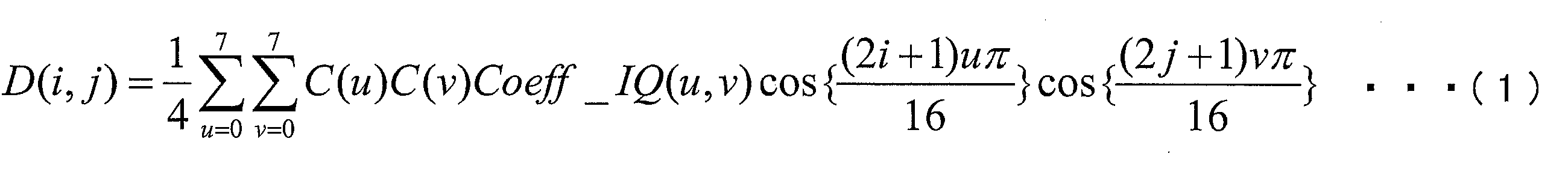
・C(u)=1/√2 (u=0)
・C(u)=1 (u≠0)
・C(v)=1/√2 (v=0)
・C(v)=1 (v≠0)
加算器14は、予測画像生成部12から供給された予測画像Predと、逆量子化・逆変換部13から供給された予測残差Dとを加算することによって復号画像Pを生成する。生成された復号画像Pは、フレームメモリ15に格納される。
ループフィルタ16は、(1)復号画像Pにおけるブロック境界、またはパーティション境界の周辺の画像の平滑化(デブロック処理)を行うデブロッキングフィルタ(DF:Deblocking Filter)としての機能と、(2)デブロッキングフィルタが作用した画像に対して、フィルタパラメータFPを用いて適応フィルタ処理を行う適応フィルタ(ALF:Adaptive Loop Filter)としての機能とを有している。
量子化残差情報復号部111は、符号化データ#1に含まれる量子化残差情報QDから、各周波数成分(xC、yC)についての量子化された変換係数Coeff(xC、yC)を復号するための構成である。ここで、xCおよびyCは、周波数領域における各周波数成分の位置を表すインデックスであり、それぞれ、上述した水平方向周波数uおよび垂直方向周波数vに対応するインデックスである。また、量子化残差情報QDに含まれる各種のシンタックスは、コンテキスト適応型2値算術符号化(CABAC:(Context-based Adaptive Binary Arithmetic Coding))によって符号化されている。なお、以下では、量子化された変換係数Coeffを、単に、変換係数Coeffと呼ぶこともある。
算術符号復号部130は、量子化残差情報QDに含まれる各ビットをコンテキストを参照して復号するための構成であり、図1に示すように、コンテキスト記録更新部131及びビット復号部132を備えている。
コンテキスト記録更新部131は、各コンテキストインデックスctxIdxによって管理されるコンテキスト変数CVを記録及び更新するための構成である。ここで、コンテキスト変数CVには、(1)発生確率が高い優勢シンボルMPS(most probable symbol)と、(2)その優勢シンボルMPSの発生確率を指定する確率状態インデックスpStateIdxとが含まれている。
ビット復号部132は、コンテキスト記録更新部131に記録されているコンテキスト変数CVを参照し、量子化残差情報QDに含まれる各ビット(Binとも呼ぶ)を復号する。また、復号して得られたBinの値を変換係数復号部120の備える各部に供給する。また、復号して得られたBinの値は、コンテキスト記録更新部131にも供給され、コンテキスト変数CVを更新するために参照される。
図1に示すように、変換係数復号部120は、ラスト係数位置復号部121、スキャン順テーブル格納部122、係数復号制御部123、係数有無フラグ復号部、係数値復号部125、復号係数記憶部126、及び、サブブロック係数有無フラグ復号部127を備えている。
ラスト係数位置復号部121は、ビット復号部132より供給される復号ビット(Bin)を解釈し、シンタックスlast_significant_coeff_x及びlast_significant_coeff_yを復号する。復号したシンタックスlast_significant_coeff_x及びlast_significant_coeff_yは、係数復号制御部123に供給される。また、ラスト係数位置復号部121は、算術符号復号部130にてシンタックスlast_significant_coeff_x及びlast_significant_coeff_yのBinを復号するために用いられるコンテキストを決定するためのコンテキストインデックスctxIdxを算出する。算出されたコンテキストインデックスctxIdxは、コンテキスト記録更新部131に供給される。
スキャン順テーブル格納部122には、処理対象のTU(ブロック)のサイズ、スキャン方向の種別を表すスキャンインデックス、及びスキャン順に沿って付与された周波数成分識別インデックスを引数として、処理対象の周波数成分の周波数領域における位置を与えるテーブルが格納されている。
また、スキャン順テーブル格納部122には、サブブロックのスキャン順を指定するためのサブブロックスキャン順テーブルが格納されている。サブブロックスキャン順テーブルは、処理対象のTU(ブロック)のサイズとイントラ予測モードの予測モードインデックス(予測方向)とに関連付けられたスキャンインデックスscanIndexによって指定される。処理対象のTUに用いられた予測方法がイントラ予測である場合には、係数復号制御部123は、当該TUのサイズと当該TUの予測モードとに関連付けられたスキャンインデックスscanIndexによって指定されるテーブルを参照してサブブロックのスキャン順を決定する。
係数復号制御部123は、量子化残差情報復号部111の備える各部における復号処理の順序を制御するための構成である。
ブロックサイズが所定のサイズ以下である場合、係数復号制御部123は、ラスト係数位置復号部121から供給されるシンタックスlast_significant_coeff_x及びlast_significant_coeff_yを参照し、順スキャンに沿った最後の非0変換係数の位置を特定すると共に、特定した最後の非0変換係数の位置を起点とするスキャン順であって、スキャン順テーブル格納部122に格納されたスキャン順テーブルよって与えられるスキャン順の逆スキャン順に、各周波数成分の位置(xC、yC)を、係数有無フラグ復号部124及び復号係数記憶部126に供給する。
ブロックサイズが所定のサイズよりも大きい場合、係数復号制御部123は、ラスト係数位置復号部121から供給されるシンタックスlast_significant_coeff_x及びlast_significant_coeff_yを参照し、順スキャンに沿った最後の非0変換係数の位置を特定すると共に、特定した最後の非0変換係数を含むサブブロックの位置を起点とするスキャン順であって、スキャン順テーブル格納部122に格納されたサブブロックスキャン順テーブルによって与えられるスキャン順の逆スキャン順に、各サブブロックの位置(xCG、yCG)を、サブブロック係数有無フラグ復号部127に供給する。
サブブロック係数有無フラグ復号部127は、ビット復号部132から供給される各Binを解釈し、各サブブロック位置(xCG、yCG)によって指定されるシンタックスsignificant_coeffgroup_flag[xCG][yCG]を復号する。また、サブブロック係数有無フラグ復号部127は、算術符号復号部130にてシンタックスsignificant_coeffgroup_flag[xCG][yCG]のBinを復号するために用いられるコンテキストを決定するためのコンテキストインデックスctxIdxを算出する。算出されたコンテキストインデックスctxIdxは、コンテキスト記録更新部131に供給される。ここで、シンタックスsignificant_coeffgroup_flag[xCG][yCG]は、サブブロック位置(xCG、yCG)によって指定されるサブブロックに、少なくとも1つの非0変換係数が含まれている場合に1をとり、非0変換係数が1つも含まれていない場合に0をとるシンタックスである。復号されたシンタックスsignificant_coeffgroup_flag[xCG][yCG]の値は、復号係数記憶部126に格納される。
本実施形態に係る係数有無フラグ復号部124は、各係数位置(xC、yC)によって指定されるシンタックスsignificant_coeff_flag[xC][yC]を復号する。復号されたシンタックスsignificant_coeff_flag[xC][yC]の値は、復号係数記憶部126に格納される。また、係数有無フラグ復号部124は、算術符号復号部130にてシンタックスsignificant_coeff_flag[xC][yC]のBinを復号するために用いられるコンテキストを決定するためのコンテキストインデックスctxIdxを算出する。算出されたコンテキストインデックスctxIdxは、コンテキスト記録更新部131に供給される。係数有無フラグ復号部124の具体的な構成については後述する。
係数値復号部125は、ビット復号部132から供給される各Binを解釈し、シンタックスcoeff_abs_level_greater1_flag、coeff_abs_level_greater2_flag、coeff_sign_flag、及びcoeff_abs_level_minus3を復号すると共に、これらのシンタックスを復号した結果に基づき、処理対象の周波数成分における変換係数(より具体的には非0変換係数)の値を導出する。また、各種シンタックスの復号に用いたコンテキストインデックスctxIdxは、コンテキスト記録更新部131に供給される。導出された変換係数の値は、復号係数記憶部126に格納される。
復号係数記憶部126は、係数値復号部125によって復号された変換係数の各値を記憶しておくための構成である。また、復号係数記憶部126には、係数有無フラグ復号部124によって復号されたシンタックスsignificant_coeff_flagの各値が記憶される。復号係数記憶部126によって記憶されている変換係数の各値は、逆量子化・逆変換部13に供給される。
以下では、図19を参照して、サブブロック係数有無フラグ復号部127の具体的な構成例について説明する。
サブブロック係数有無フラグ復号部127の備えるコンテキスト導出部127aは、各サブブロック位置(xCG、yCG)によって指定されるサブブロックに割り付けるコンテキストインデックスを導出する。サブブロックに割り付けられたコンテキストインデックスは、当該サブブロックについてのシンタックスsignificant_coeffgroup_flagを示すBinを復号する際に用いられる。また、コンテキストインデックスを導出する際には、サブブロック係数有無フラグ記憶部127bに記憶された復号済みのサブブロック係数有無フラグの値が参照される。コンテキスト導出部127aは、導出したコンテキストインデックスをコンテキスト記録更新部131に供給する。
コンテキストインデックスには、色空間を示すcIdxと、TUサイズを示すlog2TrofoSizeによって定まる所定の初期値(ctxIdxOffset)が設定される。
ctxIdx = ctxIdxOffset
(2)xCG<3、かつ、yCG==3のとき
コンテキストインデックスには、サブブロック位置(xCG、yCG)の右隣に位置する復号済みサブブロック係数有無フラグsignificant_coeffgroup_flag[xCG+1][yCG+1]の値を参照して次のように設定される。
ctxIdx = ctxIdxOffset+ significant_coeffgroup_flag[xCG+1][yCG]
(3)xCG==3、かつ、yCG<3のとき
コンテキストインデックスには、サブブロック位置(xCG、yCG)の下に位置する復号済みサブブロック係数有無フラグsignificant_coeffgroup_flag[xCG][yCG+1]の値を参照して次のように設定される。
ctxIdx = ctxIdxOffset + significant_coeffgroup_flag[xCG][yCG+1]
(4)xCG<3、かつ、yCG<3のとき
コンテキストインデックスには、サブブロック位置(xCG、yCG)の右隣に位置する復号済みサブブロック係数有無フラグsignificant_coeffgroup_flag[xCG+1][yCG]と、サブブロック位置(xCG,yCG)の下に位置する復号済サブブロック係数有無フラグsiginificant_coeffgroup_flag[xCG][yCG+1]の値を参照して次のように設定される。
ctxIdx = ctxIdxOffset + Max( significant_coeffgroup_flag[xCG+1][yCG], significant_coeffgroup_flag[xCG][yCG+1] )
なお、初期値ctxIdxOffsetは、色空間を示すcIdxと、TUサイズを示すlog2TrofoSizeによって次のように設定される。
ctxIdxOffset = cIdx==0 ? ( ( 5 ‐ log2TrafoSize ) * 16 ) + 44 :
( ( 4 - log2TrafoSize ) * 16 ) + 44 + 64
サブブロック係数有無フラグ記憶部127bには、サブブロック係数有無フラグ設定部127cによって復号又は設定されたシンタックスsignificant_coeffgroup_flagの各値が記憶されている。サブブロック係数有無フラグ設定部127cは、隣接サブブロックに割り付けられたシンタックスsignificant_coeffgroup_flagを、サブブロック係数有無フラグ記憶部127bから読み出すことができる。
サブブロック係数有無フラグ設定部127cは、ビット復号部132から供給される各Binを解釈し、シンタックスsignificant_coeffgroup_flag[xCG][yCG]を復号または設定する。より具体的には、サブブロック係数有無フラグ設定部127cは、サブブロック位置(xCG、yCG)、及び、サブブロック位置(xCG、yCG)によって指定されるサブブロックに隣接するサブブロック(隣接サブブロックとも呼ぶ)に割り付けられたシンタックスsignificant_coeffgroup_flagを参照し、シンタックスsignificant_coeffgroup_flag[xCG][yCG]を復号または設定する。また、復号または設定されたシンタックスsignificant_coeffgroup_flag[xCG][yCG]の値は、係数有無フラグ復号部124に供給される。
サブブロックスキャン順を指定するスキャンタイプが垂直方向優先スキャンである場合、サブブロック係数有無フラグ設定部127cは、図20(a)に示すように、サブブロック(xCG、yCG)に隣接するサブブロック(xCG、yCG+1)に割り付けられたサブブロック係数有無フラグsignificant_coeffgroup_flag[xCG][yCG+1]の値を参照する。significant_coeffgroup_flag[xCG][yCG+1]=1である場合、サブブロック係数有無フラグ設定部127cは、significant_coeffgroup_flag[xCG][yCG]=1に設定する。この場合、significant_coeffgroup_flag[xCG][yCG]を復号する処理を省略することができる。なお、隣接サブブロックに割り付けられたサブブロック係数有無フラグの値を当該サブブロックに割り付けられたサブブロック係数有無フラグの値に設定することを、「サブブロック係数有無フラグの推測」と表現することもある。推測されたサブブロック係数有無フラグに対しては、符号化及び復号処理が省略可能である。
サブブロックスキャン順を指定するスキャンタイプが水平方向優先スキャンである場合、サブブロック係数有無フラグ設定部127cは、図20(b)に示すように、サブブロック(xCG、yCG)に隣接するサブブロック(xCG+1、yCG)に割り付けられたサブブロック係数有無フラグsignificant_coeffgroup_flag[xCG+1][yCG]の値を参照する。significant_coeffgroup_flag[xCG+1][yCG]=1である場合、サブブロック係数有無フラグ設定部127cは、significant_coeffgroup_flag[xCG][yCG]=1に設定する。この場合、significant_coeffgroup_flag[xCG][yCG]を復号する処理を省略することができる。
サブブロックスキャン順を指定するスキャンタイプが斜め方向スキャンである場合、サブブロック係数有無フラグ設定部127cは、図20(c)に示すように、サブブロック(xCG、yCG)に隣接するサブブロック(xCG+1、yCG)に割り付けられたサブブロック係数有無フラグsignificant_coeffgroup_flag[xCG+1][yCG]の値とサブブロック(xCG、yCG+1)に割り付けられたサブブロック係数有無フラグsignificant_coeffgroup_flag[xCG][yCG+1]の値とを参照する。
比較例に係るサブブロック係数有無フラグ符号化及び復号処理では、変換係数の偏りに関わらず、斜め方向スキャンが選択されるものとする。また、DC成分を含むサブブロック及びラスト係数を含むサブブロックについては、significant_coeffgroup_flagが1に設定(推測)され、符号化されないものとする。
一方で、本実施形態に係るサブブロック係数有無フラグ符号化処理では、イントラ予測モードに応じて、スキャン方向を決定するので、変換係数の偏りの態様に適したスキャン順が選択される。また、DC成分を含むサブブロック及びラスト係数を含むサブブロックについては、significant_coeffgroup_flagが1に設定(推測)され、符号化されない。
以下では、図23を参照して、係数有無フラグ復号部124の具体的な構成例について説明する。
図23は、係数有無フラグ復号部124の構成例を示すブロック図である。図23に示すように、係数有無フラグ復号部124は、周波数分類部124a、位置コンテキスト導出部124b、周辺参照コンテキスト導出部124c、係数有無フラグ記憶部124d、及び係数有無フラグ設定部124eを備えている。
周波数分類部124aは、対象となる周波数領域のサイズが所定のサイズ以下のサイズである場合(例えば、4×4成分、8×8成分である場合)、当該所定サイズ以下の周波数領域の各周波数成分に対して、その周波数成分の位置に応じて、当該周波数成分を複数の部分領域の何れかに分類すると共に、位置コンテキスト導出部124bによって導出されたコンテキストインデックスctxIdxを割り付ける。
yCG=yC>>2 ・・・(eq.A2)
ここで、xCG=0、1、...、(sz-1)>>2であり、yCG=0、1、...、(sz-1)>>2であるとする。
(1)xCG+yCG<THA、かつ、xC+yC<THZを満たす周波数成分を部分領域R0に分類する。
(2)xCG+yCG<THA、かつ、THZ≦xC+yCを満たす周波数成分を部分領域R1に分類する。
(3)THA≦xCG+yCGを満たす周波数成分を部分領域R2に分類する。
********************************************************************
if( xCG+yCG<THA){
if( xC+yC<THZ ) {
R0へ分類
}
else{// if( xC+yC>=THZ)
R1へ分類
}
}
else{//if( xCG+yCG>=THA ){
R2へ分類
}
********************************************************************
ここで、閾値THZとして2を用いる。THAは、THA≧THZ/4を満たす閾値を表している。具体的な値としては、例えば、周波数領域のサイズ(処理対象TUのサイズ)に関わらず、THA=1とすればよい。また、周波数領域のサイズlog2TrafoSizeを用いて、THA=1<<(log2TrafoSize-2)としてもよい。すなわち、周波数領域のサイズが16×16である場合、THA=1とし、周波数領域のサイズが32×32である場合、THA=2としてもよい。このように、周波数領域のサイズに応じて、異なる閾値を用いる構成としてもよい。また、閾値THZを1としても良い。
位置コンテキスト導出部124bは、対象周波数成分に対するコンテキストインデックスctxIdxを、周波数領域における当該対象周波数成分の位置に基づいて導出する。
なお、NXはコンテキストインデックスの開始点を表す定数である。周波数領域のサイズが4×4及び8×8で用いるコンテキスト数が各々N4個、N8個の場合には、周波数領域のサイズが16×16および32×32の開始点はNX=N4+N8になる。
周辺参照コンテキスト導出部124cは、復号対象の周波数成分に対するコンテキストインデックスctxIdxを、当該周波数成分の周辺の周波数成分について復号済みの非0変換係数の数cntに基づいて導出する。
ここで、tempは、
temp=(cnt+1)>>1
によって定まる。
ここで、tempは、上記の場合と同様に、
temp=(cnt+1)>>1
によって定まる。
ここで、(eq.A6)における各項は、()内の比較が真である場合に1をとり、()内の比較が偽である場合に0をとるものとする。
・・・(eq.A7)
また、対象とする変換係数のサブブロック内の位置に応じて、数式(eq.A6)と数式(eq.A7)との何れかを用いて変換係数を導出する構成としてもよい。すなわち、対象とする変換係数のサブブロック内の位置に応じて、変換係数の導出に用いる参照成分を変更する構成としてもよい。
係数有無フラグ設定部124eは、ビット復号部132から供給される各Binを解釈し、シンタックスsignificant_coeff_flag[xC][yC]を復号または設定する。復号または設定されたシンタックスsignificant_coeff_flag[xC][yC]は、復号係数記憶部126に供給される。
係数有無フラグ記憶部124dには、シンタックスsignificant_coeff_flag[xC][yC]の各値が格納される。係数有無フラグ記憶部124dに格納されたシンタックスsignificant_coeff_flag[xC][yC]の各値は、周辺参照コンテキスト導出部124cによって参照される。
以下では、係数有無フラグ復号部124による他の処理例について図26~図28を参照して説明する。
TH=Max(width、height)>>2
によって定められる。ここで、widthは、周波数成分を単位として表現された対象周波数領域の幅を示しており、heightは周波数成分を単位として表現された対象周波数領域の高さを示している。例えば対象周波数領域の幅が16成分(16画素に対応)、高さが4成分(4画素に対応)であるとき、width=16、height=4である。
まず、周波数分類部124aは、処理対象の周波数領域が所定のサイズ以下である場合に、処理対象の周波数成分の位置(xC,yC)に基づいて、処理対象の周波数成分を4×4成分の場合はサブグループ(サブ領域)R0~R6へ、8×8成分の場合はサブグループR0~R9へ分類処理を行う。
(1)xC=0、かつ、yC=0の場合、サブグループR0へ分類する。
(2)xC=1、かつ、yC=0の場合、サブグループR1へ分類する。
(3)xC=0、かつ、yC=1の場合、サブグループR2へ分類する。
(4)xC=1、かつ、yC=1の場合、サブグループR3へ分類する。
(5)1<xC<4、かつ、yC<2の場合、サブグループR4へ分類する。
(6)xC<2、かつ、1<yC<4の場合、サブグループR5へ分類する。
(7)2≦xC<4、かつ、2≦yC<4の場合、サブグループR6へ分類する。
(1)xC=0、かつ、yC=0の場合、サブグループR0へ分類する。
(2)xC=1、かつ、yC=0の場合、サブグループR1へ分類する。
(3)xC=0、かつ、yC=1の場合、サブグループR2へ分類する。
(4)xC=1、かつ、yC=1の場合、サブグループR3へ分類する。
(5)1<xC<4、かつ、yC<2の場合、サブグループR4へ分類する。
(6)xC<2、かつ、1<yC<4の場合、サブグループR5へ分類する。
(7)2≦xC<4、かつ、2≦yC<4の場合、サブグループR6へ分類する。
(8)xC≧4、かつ、yC<4の場合、サブグループR7へ分類する。
(9)xC<4、かつ、yC≧4の場合、サブグループR8へ分類する。
(10)xC≧4、かつ、yC≧4の場合、サブグループR9へ分類する。
以上、周波数領域が所定のサイズ以下である場合に、異なる変換ブロック間において、共通のコンテキストインデックスを導出する場合について説明したが、コンテキストインデックスの導出処理はこれに限定されない。以下では、異なる変換ブロック間において、共通のコンテキストインデックスを導出しない場合について説明する。
(1)xC=0、かつ、yC=0の場合、サブグループR0へ分類する。
(2)(xC=0かつyC=0)でなく、xC<2、かつ、yC<2の場合、サブグループR1へ分類する。
(3)xC=2、かつ、yC<2の場合、サブグループR2へ分類する。
(4)xC=3、かつ、yC<2の場合、サブグループR3へ分類する。
(5)xC<2、かつ、yC=2の場合、サブグループR4へ分類する。
(6)xC<2、かつ、yC=3の場合、サブグループR5へ分類する。
(7)xC≧2、かつ、yC≧2の場合、サブグループR6へ分類する。
(1’)xC<1、かつ、yC<1の場合、サブグループR0へ分類する。
(2’)(xC<1かつyC<1)ではなく、xC<2、かつ、yC<2の場合、サブグループR1へ分類する。
(1)xC<2、かつ、yC<2の場合、サブグループR0へ分類する。
(2)(xC<2かつyC<2)でなく、xC<4、かつ、yC<4の場合、サブグループR1へ分類する。
(3)xC≧4、かつ、xC<6、かつ、yC<4の場合、サブグループR2へ分類する。
(4)xC≧6、かつ、yC<4の場合、サブグループR3へ分類する。
(5)xC<4、かつ、yC≧4、かつ、yC<6の場合、サブグループR4へ分類する。
(6)xC<4、かつ、yC≧6の場合、サブグループR5へ分類する。
(7)xC≧4、かつ、yC≧4の場合、サブグループR6へ分類する。
Y=log2TrafoSize == 2 ? yC : yC>>1
続いて、導出した変数X、Yに基づいて、処理対象の周波数成分(xC、yC)をサブグループR0~R6へ分類処理を行う。
(2)(X=0かつY=0)でなく、X<2、かつ、Y<2の場合、サブグループR1へ分類する。
(3)X=2、かつ、Y<2の場合、サブグループR2へ分類する。
(4)X=3、かつ、Y<2の場合、サブグループR3へ分類する。
(5)X<2、かつ、Y=2の場合、サブグループR4へ分類する。
(6)X<2、かつ、Y=3の場合、サブグループR5へ分類する。
(7)X≧2、かつ、Y≧2の場合、サブグループR6へ分類する。
(2)xC<width/2、かつ、yC<width/2の場合、サブグループR1へ分類する。
(3)xC≧width/2、かつ、xC<width×3/4、かつ、yC<width/2の場合、サブグループR2へ分類する。
(4)xC≧width×3/4、かつ、yC<width/2の場合、サブグループR3へ分類する。
(5)xC<width/2、かつ、yC≧width/2、かつ、yC<width×3/4の場合、サブグループR4へ分類する。
(6)xC<width/2、かつ、yC≧width×3/4の場合、サブグループR5へ分類する。
(7)xC≧width/2、かつ、yC≧width/2の場合、サブグループR6へ分類する。
ここでwidthは、対象周波数領域の幅(4×4では4、8×8では8)である。
ctxIdx(i) = i + offsetBlk
なお、iは、サブグループRiを識別する番号を表わし、offsetBlkは、4×4成分と8×8成分のコンテキストインデックスを識別するためのオフセットであり、変換ブロックの横幅サイズの対数値を示すlog2TrafoWidthによって所定の値が設定される。よって、輝度の4×4成分の各サブグループRiのコンテキストインデックスctxIdx(i)は、図62(b)に示すように設定され、輝度の8×8成分の各サブグループRiのコンテキストインデックスctxIdx(i)は、図62(c)に示すように設定される。
ctxIdx(i) = i + offsetClr + offsetBlk
なお、iは、サブグループRiを識別する番号を表わし、offsetBlkは、4×4成分と8×8成分のコンテキストインデックスを識別するためのオフセットであり、変換ブロックの横幅サイズの対数値を示すlog2TrafoWidthに応じて所定の値が設定される。offsetClrは
、輝度と色差のコンテキストインデックスを識別するための所定のオフセットである。例えば、offsetClr=14とすれば、色差の4×4成分の各サブグループRiのコンテキストインデックスctxIdx(i)は、図63(a)に示すように設定され、色差の8×8成分の各サブグループRiのコンテキストインデックスctxIdx(i)は、図63(b)に示すように設定される。
ストインデックスを図63(a)、(b)に図示しているが、これに限定されない。offsetClrは、4×4変換ブロック~32×32変換ブロックの輝度のコンテキスインデックスの総数であることが好ましい。
また、各変換ブロックの輝度のコンテキストインデックスctxIdxは、次の式により導出される。
(4×4成分の場合)
ctxIdx=CTX_IND_MAP[ index ]
(8×8成分の場合)
ctxIdx=CTX_IND_MAP[ index ] + sigCtxOffset
ここで、sigCtxOffsetは、4×4成分のコンテキストインデックスと8×8成分のコンテキストインデックスを識別するための所定のオフセットである。
(4×4成分の場合)
ctxIdx=CTX_IND_MAP[ index ] + SigCtxOffsetLuma
(8×8成分の場合)
ctxIdx=CTX_IND_MAP[ index ] + sigCtxOffset + SigCtxOffsetLuma
ここで、sigCtxOffsetは、4×4成分のコンテキストインデックスと8×8成分、16×4成分、4×16成分のコンテキストインデックスを識別するための所定のオフセットであり、SigCtxOffsetLumaは輝度と色差のコンテキストインデックスを識別するための所定のオフセットである。
周波数領域が所定のサイズ以下である場合の周波数分類部124aによる周波数分類処理と、位置コンテキスト導出部124bによるコンテキストインデックス導出処理の具体例3を、図64~図65を更に参照して説明する。
また、各変換ブロックの輝度のコンテキストインデックスctxIdxは、次の式により導出される。
(4×4成分の場合)
ctxIdx=CTX_IND_MAP[ index ]
(8×8成分の場合)
ctxIdx=CTX_IND_MAP[ index ] + sigCtxOffset
ここで、sigCtxOffsetは、4×4成分のコンテキストインデックスと8×8成分のコンテキストインデックスを識別するための所定のオフセットである。
(4×4成分の場合)
ctxIdx=CTX_IND_MAP[ index ] + SigCtxOffsetLuma
(8×8成分の場合)
ctxIdx=CTX_IND_MAP[ index ] + sigCtxOffset + SigCtxOffsetLuma
ここで、sigCtxOffsetは、4×4成分のコンテキストインデックスと8×8成分、16×4成分、4×16成分のコンテキストインデックスを識別するための所定のオフセットであり、SigCtxOffsetLumaは輝度と色差のコンテキストインデックスを識別するための所定のオフセットである。
周波数領域が所定のサイズ以下である場合の周波数分類部124aによる周波数分類処理と、位置コンテキスト導出部124bによるコンテキストインデックス導出処理の具体例の具体例3では、輝度と色差の両方に関して、非ゼロ係数の発生頻度が水平方向周波数成分uと垂直方向周波数成分vとがu=vとなる境界を境にして出現頻度が対称となる特性を利用して、周波数分類部124aで分類された各サブグループに対して、コンテキストインデックスを割り当てる例について説明した。
また、各変換ブロックの輝度のコンテキストインデックスctxIdxは、次の式により導出される。
(4×4成分の場合)
ctxIdx=CTX_IND_MAP_L[ index ]
(8×8成分の場合)
ctxIdx=CTX_IND_MAP_L[ index ] + sigCtxOffset
ここで、sigCtxOffsetは、4×4成分のコンテキストインデックスと8×8成分のコンテキストインデックスを識別するための所定のオフセットである。
(4×4成分の場合)
ctxIdx=CTX_IND_MAP_C[ index ] + SigCtxOffsetLuma
(8×8成分の場合)
ctxIdx=CTX_IND_MAP_C[ index ] + sigCtxOffset + SigCtxOffsetLuma
ここで、sigCtxOffsetは、4×4成分のコンテキストインデックスと8×8成分のコンテキストインデックスを識別するための所定のオフセットであり、SigCtxOffsetLumaは輝度と色差のコンテキストインデックスを識別するための所定のオフセットである。
具体例2~具体例4では、4×4変換ブロックと8×8変換ブロックにおける周波数成分の分類処理を共通化する場合について説明したが、分類処理はこれに限定されない。例えば、図60(b)の8×8変換ブロックの領域R0において、DC成分をさらに別のサブグループR7として分類してもよい。すなわち、4×4成分のサイズを有する周波数領域の分割パターンと、8×8成分のサイズを有する周波数領域の分割パターンとが、DC成分を除く周波数領域において、互いに相似となるように周波数領域をサブ領域(サブグループ)へ分割してもよい。
(1)xC=0、かつ、yC=0の場合、サブグループR0へ分類する。
(2)(xC=0かつyC=0)でなく、xC<2、かつ、yC<2の場合、サブグループR1へ分類する。
(3)xC=2、かつ、yC<2の場合、サブグループR2へ分類する。
(4)xC=3、かつ、yC<2の場合、サブグループR3へ分類する。
(5)xC<2、かつ、yC=2の場合、サブグループR4へ分類する。
(6)xC<2、かつ、yC=3の場合、サブグループR5へ分類する。
(7)xC≧2、かつ、yC≧2の場合、サブグループR6へ分類する。
上記(1)及び(2)は下記(1’)及び(2’)によっても処理することができる。
(2’)(xC<1かつyC<1)ではなく、xC<2、かつ、yC<2の場合、サブグループR1へ分類する。
(1)xC=0、かつ、yC=0の場合、サブグループR7へ分類する。
(2)(xC=0かつyC=0)でなく、xC<2、かつ、yC<2の場合、サブグループR0へ分類する。
(3)(xC<2かつyC<2)でなく、xC<4、かつ、yC<4の場合、サブグループR1へ分類する。
(4)xC≧4、かつ、xC<6、かつ、yC<4の場合、サブグループR2へ分類する。
(5)xC≧6、かつ、yC<4の場合、サブグループR3へ分類する。
(6)xC<4、かつ、yC≧4、かつ、yC<6の場合、サブグループR4へ分類する。
(7)xC<4、かつ、yC≧6の場合、サブグループR5へ分類する。
(8)xC≧4、かつ、yC≧4の場合、サブグループR6へ分類する。
まず、周波数分類部124aは、次に示す式により、処理対象の周波数成分の位置(xC,yC)と、変換ブロックのサイズを示すlog2TrafoSizeに基づいて、変数X,Yを算出する。
Y=log2TrafoSize == 2 ? yC : yC>>1
続いて、導出した変数X、Yに基づいて、処理対象の周波数成分(xC、yC)をサブグループR0~R6へ分類処理を行う。
(2)(X=0かつY=0)でなく、X<2、かつ、Y<2の場合、サブグループR1へ分類する。
(3)X=2、かつ、Y<2の場合、サブグループR2へ分類する。
(4)X=3、かつ、Y<2の場合、サブグループR3へ分類する。
(5)X<2、かつ、Y=2の場合、サブグループR4へ分類する。
(6)X<2、かつ、Y=3の場合、サブグループR5へ分類する。
(7)X≧2、かつ、Y≧2の場合、サブグループR6へ分類する。
(2)xC<width/2、かつ、yC<width/2の場合、サブグループR1へ分類する。
(3)xC≧width/2、かつ、xC<width×3/4、かつ、yC<width/2の場合、サブグループR2へ分類する。
(4)xC≧width×3/4、かつ、yC<width/2の場合、サブグループR3へ分類する。
(5)xC<width/2、かつ、yC≧width/2、かつ、yC<width×3/4の場合、サブグループR4へ分類する。
(6)xC<width/2、かつ、yC≧width×3/4の場合、サブグループR5へ分類する。
(7)xC≧width/2、かつ、yC≧width/2の場合、サブグループR6へ分類する。
ここでwidthは、対象周波数領域の幅(4×4では4、8×8では8)である。
ctxIdx(i) = i + offsetBlk
なお、iは、サブグループRiを識別する番号を表わし、offsetBlkは、4×4成分と8×8成分のコンテキストインデックスを識別するためのオフセットであり、変換ブロックの横幅サイズの対数値を示すlog2TrafoWidthによって所定の値が設定される。
ctxIdx(i) = i + offsetClr + offsetBlk
なお、iは、サブグループRiを識別する番号を表わし、offsetBlkは、4×4成分と8×8成分のコンテキストインデックスを識別するためのオフセットであり、変換ブロックの横幅サイズの対数値を示すlog2TrafoWidthに応じて所定の値が設定される。offsetClrは、輝度と色差のコンテキストインデックスを識別するための所定のオフセットである。ここで、offsetClr=20とした場合に、色差に関して、上記式により導出される4×4成分の各サブ領域Riに対応するコンテキストインデックスctxIdx(i)を図88(c)に示し、8×8成分の各サブ領域Riに対応するコンテキストインデックスctxIdx(i)を図88(d)に示す。なお、説明上、輝度と色差のコンテキストインデックスを識別するためのオフセットoffsetClrをoffsetClr=20として、色差のコンテキストインデックスを図88(c)、(d)に図示しているが、これに限定されない。offsetClrは、4×4変換ブロック~32×32変換ブロックの輝度のコンテキスインデックスの総数であることが好ましい。
処理対象の周波数成分(xC,yC)が属するサブブロック(4×4の場合は1×1サブブロック)の位置(X,Y)に対応するインデックス値indexを、次の式により算出する。
ただし、 X=xC, Y=yCである。続いて、求めたインデックス値indexとルックアップテーブルCTX_IND_MAP[ index ]からコンテキストインデックスctxIdxを次の式により導出する。
なお、色差の場合は、上記の式により算出したコンテキストインデックスctxIdxと所定のオフセットoffsetClrを用いて、次の式によりコンテキストインデックスを導出する。
なお、offsetClrは、輝度と色差のコンテキストインデックスを識別するための所定のオフセットである。
処理対象の周波数成分(xC,yC)が属するサブブロック(8×8の場合は2×2サブブロック)の位置(X,Y)、及びDC成分に対応するインデックス値indexは、次の式により算出される。
ただし、X=xC>>1, Y=yC>>1である。続いて、求めたインデックス値indexとルックアップテーブルCTX_IND_MAP[ index ]と、4×4成分と8×8成分のコンテキストインデックスを識別するための所定のオフセットoffsetBlkを用いて、コンテキストインデックスctxIdxを次の式により導出する。
ここで、4×4成分の輝度のコンテキストインデックスの総数は7であるため、offsetBlk=7となる。なお、色差の場合は、上記の式により算出したコンテキストインデックスctxIdxと所定のオフセットoffsetClrを用いて、次の式によりコンテキストインデックスを導出する。
なお、offsetClrは、輝度と色差のコンテキストインデックスを識別するための所定のオフセットである。
したがって、図70(a)、(b)に示す例において、輝度に関して15個のコンテキストインデックスが導出され、色差に関して15個のコンテキストインデックスが導出され、15+15=30個のコンテキストインデックスが導出される。これは、図30(a)~(c)に示した比較例において導出される37個よりも7個少ない。
具体例2では、変換ブロックサイズが4×4ブロック(4×4成分)、8×8ブロック(8×8成分)に関して、処理対象の周波数成分をサブグループへ分類処理を共通化し、コンテキストインデックス導出処理を簡略化する場合について説明した。ここでは、さらに横幅16、縦幅4の16×4ブロック(16×4成分)、及び横幅4、縦幅16の4×16ブロック(4×16成分)に適用する場合について説明する。
(16×4成分の場合)
(1)0≦xC<4、かつ、yC=0の場合、サブグループA0へ分類する。
(2)(0≦xC<4、かつ、yC=0)でなく、0≦xC<8、かつ、0≦yC<2の場合、サブグループA1へ分類する。
(3)8≦xC<12、かつ、0≦yC<2の場合、サブグループA2へ分類する。
(4)12≦xC<16、かつ、0≦yC<2の場合、サブグループA3へ分類する。
(5)0≦xC<8、かつ、yC=2の場合、サブグループA4へ分類する。
(6)0≦xC<8、かつ、yC=3の場合、サブグループA5へ分類する。
(7)8≦xC<16、かつ、2≦yC<4の場合、サブグループA6へ分類する。
(4×16成分の場合)
(1)xC=0、かつ、0≦yC<4の場合、サブグループA0へ分類する。
(2)(xC=0、かつ、0≦yC<4)でなく、0≦xC<2、かつ、0≦yC<8の場合、サブグループA1へ分類する。
(3)xC=2、かつ、0≦yC<8の場合、サブグループA2へ分類する。
(4)xC=3、かつ、0≦yC<8の場合、サブグループA3へ分類する。
(5)0≦xC<2、かつ、8≦yC<12の場合、サブグループA4へ分類する。
(6)0≦xC<2、かつ、12≦yC<16の場合、サブグループA5へ分類する。
(7)2≦xC<4、かつ、8≦yC<16の場合、サブグループA6へ分類する。
Y=log2TrafoHeight==2 ? yC : yC>>2
続いて、導出したサブブロック位置(X,Y)に基づいて、処理対象の周波数成分(xC,yC)をサブグループA0~A6へ分類処理を行う。
(2)(X=0かつY=0)でなく、X<2、かつ、Y<2の場合、サブグループA1へ分類する。
(3)X=2、かつ、Y<2の場合、サブグループA2へ分類する。
(4)X=3、かつ、Y<2の場合、サブグループA3へ分類する。
(5)X<2、かつ、Y=2の場合、サブグループA4へ分類する。
(6)X<2、かつ、Y=3の場合、サブグループA5へ分類する。
(7)X≧2、かつ、Y≧2の場合、サブグループA6へ分類する。
る共通処理は、次のように処理することもできる。
(2)xC<width/2、かつ、yC<height/2の場合、サブグループA1へ分類する。
(3)xC≧width/2、かつ、xC<width×3/4、かつ、yC<height/2の場合、サブグループA2へ分類する。
(4)xC≧width×3/4、かつ、yC<height/2の場合、サブグループA3へ分類する。
(5)xC<width/2、かつ、yC≧height/2、かつ、yC<height×3/4の場合、サブグループA4へ分類する。
(6)xC<width/2、かつ、yC≧height×3/4の場合、サブグループA5へ分類する。
(7)xC≧width/2、かつ、yC≧height/2の場合、サブグループA6へ分類する。
また、4×16変換ブロックの場合、サブブロック(4×1サブブロック)の位置(X、Y)から定まるインデックス値indexは、サブブロックを縦方向に走査した順番(開始値は0)を表わし、次の式により算出される。
また、各変換ブロックの輝度のコンテキストインデックスctxIdxは、次の式により導出される。
(4×4成分の場合)
ctxIdx=CTX_IND_MAP [ index ]
(8×8成分、16×4成分、4×16成分の場合)
ctxIdx=CTX_IND_MAP [ index ] + sigCtxOffset
ここで、sigCtxOffsetは、4×4成分のコンテキストインデックスと8×8成分、16×4成分、4×16成分のコンテキストインデックスを識別するための所定のオフセットである。
(4×4成分の場合)
ctxIdx=CTX_IND_MAP [ index ] + SigCtxOffsetLuma
(8×8成分、16×4成分、4×16成分の場合)
ctxIdx=CTX_IND_MAP [ index ] + sigCtxOffset + SigCtxOffsetLuma
ここで、sigCtxOffsetは、4×4成分のコンテキストインデックスと8×8成分、16×4成分、4×16成分のコンテキストインデックスを識別するための所定のオフセットであり、SigCtxOffsetLumaは輝度と色差のコンテキストインデックスを識別するための所定のオフセットである。
また、4×16変換ブロックの場合、サブブロック(4×1サブブロック)の位置(X、Y)から定まるインデックス値indexは、サブブロックを縦方向に走査した順番(開始値は0)を表わし、次の式により算出される。
また、各変換ブロックの輝度のコンテキストインデックスctxIdxは、次の式により導出される。
(4×4成分の場合)
ctxIdx=CTX_IND_MAP_L[ index ]
(8×8成分、16×4成分、4×16成分の場合)
ctxIdx=CTX_IND_MAP_L[ index ] + sigCtxOffset
ここで、sigCtxOffsetは、4×4成分のコンテキストインデックスと8×8成分、16×4成分、4×16成分のコンテキストインデックスを識別するための所定のオフセットである。
(4×4成分の場合)
ctxIdx=CTX_IND_MAP_C[ index ] + SigCtxOffsetLuma
(8×8成分、16×4成分、4×16成分の場合)
ctxIdx=CTX_IND_MAP_C[ index ] + sigCtxOffset + SigCtxOffsetLuma
ここで、sigCtxOffsetは、4×4成分のコンテキストインデックスと8×8成分、16×4成分、4×16成分のコンテキストインデックスを識別するための所定のオフセットであり、SigCtxOffsetLumaは輝度と色差のコンテキストインデックスを識別するための所定のオフセットである。
周波数領域が所定のサイズ以下である場合の周波数分類部124aによる周波数分類処理と、位置コンテキスト導出部124bによるコンテキストインデックス導出処理の具体例7では、4×4成分のサイズを有する周波数領域の分割パターンと、8×8成分のサイズを有する周波数領域の分割パターンが互いに相似となるように周波数領域をサブ領域(サブグループ)へ分割し、各サブ領域に個別のコンテキストインデックスを導出する場合について、図85~図87を用いて説明する。
(1)xC<2、かつ、yC<2を満たす場合、次の(1-a)~(1-d)の条件によりサブ領域R0~R3へ分類する。
(1-a)xC<1、かつ、yC<1の場合、サブ領域R0へ分類する。
(1-b)xC≧1、かつ、yC<1の場合、サブ領域R1へ分類する。
(1-c)xC<1、かつ、yC≧1の場合、サブ領域R2へ分類する。
(1-d)xC≧1、かつ、yC≧1の場合、サブ領域R3へ分類する。
(2)xC≧2、かつ、yC<2の場合、次の(2-a)~(2-b)の条件により、サブ領域R4、またはR5へ分類する。
(2-a)xC<3の場合、サブ領域R4へ分類する。
(2-b)xC≧3の場合、サブ領域R5へ分類する。
(3)xC<2、かつ、yC≧2の場合、次の(3-a)~(3-b)の条件により、サブ領域R6、またはR7へ分類する。
(3-a)yC<3の場合、サブ領域R6へ分類する。
(3-b)yC≧3の場合、サブ領域R7へ分類する。
(4)xC≧2、かつ、yC≧2の場合、サブ領域R8へ分類する。
(1)xC<4、かつ、yC<4を満たす場合、次の(1-a)~(1-d)の条件によりサブ領域R0~R3へ分類する。
(1-a)xC<2、かつ、yC<2の場合、サブ領域R0へ分類する。
(1-b)xC≧2、かつ、yC<2の場合、サブ領域R1へ分類する。
(1-c)xC<2、かつ、yC≧2の場合、サブ領域R2へ分類する。
(1-d)xC≧2、かつ、yC≧2の場合、サブ領域R3へ分類する。
(2)xC≧4、かつ、yC<4の場合、次の(2-a)~(2-b)の条件により、サブ領域R4、またはR5へ分類する。
(2-a)xC<6の場合、サブ領域R4へ分類する。
(2-b)xC≧6の場合、サブ領域R5へ分類する。
(3)xC<4、かつ、yC≧4の場合、次の(3-a)~(3-b)の条件により、サブ領域R6、またはR7へ分類する。
(3-a)yC<6の場合、サブ領域R6へ分類する。
(3-b)yC≧6の場合、サブ領域R7へ分類する。
(4)xC≧4、かつ、yC≧4の場合、サブ領域R8へ分類する。
Y=log2TrafoHeight==2 ? yC : yC>>1
続いて、導出したサブブロック位置(X,Y)に基づいて、処理対象の周波数成分(xC,yC)をサブ領域R0~R8へ分類処理を行う。
(1-a)X<1、かつ、Y<1の場合、サブ領域R0へ分類する。
(1-b)X≧1、かつ、Y<1の場合、サブ領域R1へ分類する。
(1-c)X<1、かつ、Y≧1の場合、サブ領域R2へ分類する。
(1-d)X≧1、かつ、Y≧1の場合、サブ領域R3へ分類する。
(2)X≧2、かつ、Y<2の場合、次の(2-a)~(2-b)の条件により、サブ領域R4、またはR5へ分類する。
(2-a)X<3の場合、サブ領域R4へ分類する。
(2-b)X≧3の場合、サブ領域R5へ分類する。
(3)X<2、かつ、Y≧2の場合、次の(3-a)~(3-b)の条件により、サブ領域R6、またはR7へ分類する。
(3-a)Y<3の場合、サブ領域R6へ分類する。
(3-b)Y≧3の場合、サブ領域R7へ分類する。
(4)X≧2、かつ、Y≧2の場合、サブ領域R8へ分類する。
また、上記4×4成分と8×8成分をサブ領域へ分類する共通処理は、次のように処理することもできる。
(1-a)xC<width/4、かつ、yC<height/4の場合、サブ領域R0へ分類する。
(1-b)xC≧width/4、かつ、yC<height/4の場合、サブ領域R1へ分類する。
(1-c)xC<width/4、かつ、yC≧height/4の場合、サブ領域R2へ分類する。
(1-d)xC≧width/4、かつ、yC≧height/4の場合、サブ領域R3へ分類する。
(2)xC≧width/2、かつ、yC<height/2の場合、次の(2-a)~(2-b)の条件により、サブ領域R4、またはR5へ分類する。
(2-a)xC<width×3/4の場合、サブ領域R4へ分類する。
(2-b)xC≧width×3/4の場合、サブ領域R5へ分類する。
(3)xC<width/2、かつ、yC≧height/2の場合、次の(3-a)~(3-b)の条件により、サブ領域R6、またはR7へ分類する。
(3-a)yC<height×3/4の場合、サブ領域R6へ分類する。
(3-b)yC≧height×3/4の場合、サブ領域R7へ分類する。
(4)xC≧width/2、かつ、yC≧height/2の場合、サブ領域R8へ分類する。
ここでwidthは、対象周波数領域の横幅(4×4では4、8×8では8)である。またheightは、対象周波数領域の縦幅(4×4では4、8×8では8)である。
ctxIdx(i) = i + offsetBlk
なお、iは、サブ領域Riを識別する番号を表わし、offsetBlkは、4×4成分のコンテキストインデックスと8×8成分のコンテキストインデックスを識別するためのオフセットであり、変換ブロックの横幅サイズの対数値を示すlog2TrafoWidthによって所定の値が設定される。
ctxIdx(i) = i + offsetClr + offsetBlk
なお、iは、サブ領域Riを識別する番号を表わし、offsetBlkは、4×4成分のコンテキストインデックスと8×8成分のコンテキストインデックスを識別するためのオフセットであり、変換ブロックの横幅サイズの対数値を示すlog2TrafoWidthに応じて所定の値が設定される。offsetClrは、輝度と色差のコンテキストインデックスを識別するための所定のオフセットである。ここでoffsetClr=20とした場合に、色差に関して、上記式により導出される4×4成分、及び8×8成分のコンテキストインデックスを図86(c)、(d)に示す。図86(c)は、色差の4×4成分の各サブ領域Riに対応するコンテキストインデックスctxIdx(i)を示し、図86(d)は、色差の8×8成分の各サブ領域Riに対応するコンテキストインデックスctxIdx(i)を示す。なお、説明上、輝度と色差のコンテキストインデックスを識別するためのオフセットoffsetClrをoffsetClr=20として、色差のコンテキストインデックスを図86(c)、(d)に図示しているが、これに限定されない。offsetClrは、4×4変換ブロック~32×32変換ブロックの輝度のコンテキスインデックスの総数であることが好ましい。
Y=log2TrafoHeight==2 ? yC : yC>>1
4×4成分と8×8成分の場合、各サブブロック(4×4の場合は1×1サブブロック、8×8の場合は2×2サブブロック)の位置(X,Y)から定まるインデックス値indexは、次式により導出される。なお、インデックス値indexは、サブブロックを横方向に走査した順番(開始値は0)を表わす。
また、各サブブロックに対応する輝度のコンテキストインデックスctxIdxは、次式により導出される。
ctxIdx = CTX_IND_MAP[ index ] + offsetBlk
ここで、offsetBlkは4×4成分と8×8成分のコンテキストインデックスを識別するためのオフセットであり、変換ブロックの横幅サイズの対数値を示すlog2TrafoWidthに応じて所定の値が設定される。
ctxIdx = CTX_IND_MAP[ index ] + offsetBlk
ctxIdx = ctxIdx + offsetClr
ここで、offsetBlkは4×4成分と8×8成分のコンテキストインデックスを識別するためのオフセットであり、変換ブロックの横幅サイズの対数値を示すlog2TrafoWidthに応じて所定の値が設定される。また、offsetClrは輝度と色差のコンテキストインデックスを識別するための所定のオフセットである。
周波数領域が所定のサイズ以下である場合の周波数分類部124aによる周波数分類処理と、位置コンテキスト導出部124bによるコンテキストインデックス導出処理の具体例8では、最小の変換ブロックサイズであるM×M成分(例えば4×4)のサイズを有する周波数領域の分割パターンが輝度と色差とで共通となるように、周波数領域をサブグループへ分割し、各サブグループに対応するコンテキストインデックスを導出する場合について、図90~図91、図30、図60、図62、図63を用いて説明する。
(1-a)xC<width/4、かつ、yC<height/4の場合、サブグループR0へ分類する。
(1-b)xC≧width/4、または、yC≧height/4の場合、サブグループR1へ分類する。
(2)xC≧width/2、かつ、yC<height/2の場合、次の(2-a)~(2-b)の条件により、サブグループR2、またはR3へ分類する。
(2-a)xC<width×3/4の場合、サブグループR2へ分類する。
(2-b)xC≧width×3/4の場合、サブグループR3へ分類する。
(3)xC<width/2、かつ、yC≧height/2の場合、次の(3-a)~(3-b)の条件により、サブグループR4、またはR5へ分類する。
(3-a)yC<height×3/4の場合、サブグループR4へ分類する。
(3-b)yC≧height×3/4の場合、サブグループR5へ分類する。
(4)xC≧width/2、かつ、yC≧height/2の場合、サブグループR6へ分類する。
ここでwidthは、対象周波数領域の横幅(4×4では4)である。またheightは、対象周波数領域の縦幅(4×4では4)である。上記分類処理を4×4成分に適用した例は、図60(a)に示す通りである。
なお、iは、サブグループRiを識別する番号を表わし、offsetClrは、輝度と色差のコンテキストインデックスを識別するためのオフセットであり、4×4変換ブロック~32×32変換ブロックの輝度のコンテキスインデックスの総数であることが好ましい。また、cIdxは、輝度と色差を識別するための変数であり、輝度の場合、cIdx=0、色差の場合、cIdx=1となる。
続いて、コンテキストインデックスctxIdxは、次の式により導出される。
また、色差の場合は、上記の式により導出したコンテキストインデックスctxIdxへ所定のオフセットoffsetClrを加算し、コンテキストインデックスを導出する。すなわち、
ctxIdx = ctxIdx + offsetClr
図90(b)は、図90(a)に示す疑似コードにおけるCTX_IND_MAP[index]の一例を示す図であり、図62(b)は、図90(a)に示す疑似コードに対して、図90(b)のCTX_IND_MAP [index]を用いた場合に得られる、4×4成分の輝度に関する各コンテキストインデックスの値を示している。また、図63(a)は、図90(a)に示す疑似コードに対して、図90(b)のCTX_IND_MAP[index]を用いた場合に得られる、4×4成分の色差に関する各コンテキストインデックスを示している。なお、図62(b)に示す例において、最も高周波成分側に位置する周波数成分(図62(b)において網掛けが付された周波数成分)に対しては、コンテキストインデックスは導出されない(図63(a)においても同様)。なお、説明上、輝度と色差のコンテキストインデックスを識別するためのオフセットoffsetClrをoffsetClr=14として、色差のコンテキストインデックスを図63(a)に図示しているが、これに限定されない。offsetClrは、4×4変換ブロック~32×32変換ブロックの輝度のコンテキスインデックスの総数であることが好ましい。
周波数領域が所定のサイズ以下である場合の周波数分類部124aによる周波数分類処理と、位置コンテキスト導出部124bによるコンテキストインデックス導出処理の具体例9では、最小の変換ブロックサイズであるM×M成分(例えば4×4)のサイズを有する周波数領域の分割パターンが、輝度と色差とで共通となるように周波数領域をサブグループへ分割し、各サブグループに対応するコンテキストインデックスを導出する場合について、図90~91、図85、図86を用いて説明する。
(1-a)xC<width/4、かつ、yC<height/4の場合、サブグループR0へ分類する。
(1-b)xC≧width/4、かつ、yC<height/4の場合、サブグループR1へ分類する。
(1-c)xC<width/4、かつ、yC≧height/4の場合、サブグループR2へ分類する。
(1-d)xC≧width/4、かつ、yC≧height/4の場合、サブグループR3へ分類する。
(2)xC≧width/2、かつ、yC<height/2の場合、次の(2-a)~(2-b)の条件により、サブグループR4、またはR5へ分類する。
(2-a)xC<width×3/4の場合、サブグループR4へ分類する。
(2-b)xC≧width×3/4の場合、サブグループR5へ分類する。
(3)xC<width/2、かつ、yC≧height/2の場合、次の(3-a)~(3-b)の条件により、サブグループR6、またはR7へ分類する。
(3-a)yC<height×3/4の場合、サブグループR6へ分類する。
(3-b)yC≧height×3/4の場合、サブグループR7へ分類する。
(4)xC≧width/2、かつ、yC≧height/2の場合、サブグループR8へ分類する。
ここでwidthは、対象周波数領域の横幅(4×4では4)である。またheightは、対象周波数領域の縦幅(4×4では4)である。
なお、iは、サブグループRiを識別する番号を表わし、offsetClrは、輝度と色差のコンテキストインデックスを識別するためのオフセットであり、4×4変換ブロック~32×32変換ブロックの輝度のコンテキスインデックスの総数であることが好ましい。また、cIdxは、輝度と色差を識別するための変数であり、輝度の場合、cIdx=0、色差の場合、cIdx=1となる。
続いて、コンテキストインデックスctxIdxは、次の式により導出される。
また、色差の場合は、上記の式により算出したコンテキストインデックスctxIdxに所定のオフセットoffsetClrを加算し、コンテキストインデックスを導出する。すなわち、
ctxIdx = ctxIdx + offsetClr
図90(c)は、図90(a)に示す疑似コードにおけるCTX_IND_MAP[index]の一例を示す図であり、図86(a)は、図90(a)に示す疑似コードに対して、図90(c)のCTX_IND_MAP [index]を用いた場合に得られる、4×4成分の輝度に関する各コンテキストインデックスの値を示している。また、図86(c)は、図90(a)に示す疑似コードに図90(c)のCTX_IND_MAP[index]を用いた場合に得られる、4×4成分の色差に関する各コンテキストインデックスを示している。なお、図86(a)に示す例において、最も高周波成分側に位置する周波数成分(図86(a)において網掛けが付された周波数成分)に対しては、コンテキストインデックスは導出されない(図86(c)においても同様)。なお、説明上、輝度と色差のコンテキストインデックスを識別するためのオフセットoffsetClrをoffsetClr=20として、色差のコンテキストインデックスを図86(c)に図示しているが、これに限定されない。offsetClrは、4×4変換ブロック~32×32変換ブロックの輝度のコンテキスインデックスの総数であることが好ましい。
周波数領域が所定のサイズ以下である場合の周波数分類部124aによる周波数分類処理と、位置コンテキスト導出部124bによるコンテキストインデックス導出処理の具体例9~10では、最小の変換ブロックサイズであるM×M成分(例えば4×4)のサイズを有する周波数領域の分割パターンが、輝度と色差とで共通となるように周波数領域をサブグループへ分割し、各サブグループに個別のコンテキストインデックスを導出する例、あるいは、処理対象の周波数周成分の位置(xC、yC)とルックアップテーブルを用いて、処理対象の周波数成分(xC、yC)のコンテキストインデックスctxIdxを導出する例について説明した。以下では、ルックアップテーブルを用いずに、処理対象の周波数成分の位置(xC、yC)を用いた演算式により、コンテキストインデックスを導出する例について説明する。
なお、色差の場合は、式(eq.e1)により導出されたctxIdxに、輝度と色差のコンテキストインデックスを識別するための所定のオフセットoffsetClrを加算する。すなわち、
ctxIdx = ctxIdx + offsetClr
なお、offsetClrは、4×4変換ブロック~32×32変換ブロックの輝度のコンテキスインデックスの総数であることが好ましい。
ここで、式(eq.e2)において、a = 1、 b = 1とすれば、4×4成分に関して、図92(b)に示す輝度のコンテキストインデックスが導出される。
ここで、式(eq.e3)において、th = 3、d = 4とすれば、4×4成分に関して、図92(d)に示す輝度のコンテキストインデックスが導出される。
式(eq.f1)を4×4成分に適用した場合に導出される、輝度のコンテキストインデックスの例を図93(a)に示す。図93(a)に示すように、周波数領域は、DCから高周波成分に向かって、逆L字型のサブ領域に分割されると共に、各サブ領域に対応するコンテキストインデックスctxIdxが導出されている。このように、DCから高周波成分に向かって逆L字型に分割するパターンは、非ゼロ係数の発生頻度の分布形状の良い近似であり、非ゼロ係数の発生頻度が同程度になる周波数成分に対して共通のコンテキストインデックスを割り付けることができる。
ここで、式(eq.f2)において、th = 3、a = 4とすれば、4×4成分に関して、図93(b)に示す輝度のコンテキストインデックスが導出される。
ここで、式(eq.f3)において、th = 1、a= 4とすれば、4×4成分に関して、図93(d)に示す輝度のコンテキストインデックスが導出される。
a : yC < (height/2) ? max ( xC, yC ) : max ( xC, yC ) + b
・・・(eq.f4)
ここで、式(eq.f4)において、th = 1、a = 6、b = 2、height = 4とすれば、4×4成分に関して、図93(e)に示す輝度のコンテキストインデックスが導出される。図93(e)に示す4×4成分の分割パターンは、図60(a)に示す4×4成分の周波数成分の分割パターンを表現することができる。
Y = yC >> (log2TrafoHeight-2)
ctxIdx = ( (X>>1) + (Y>>1) > th ) ?
a : ( Y < (1<<(log2TrafoHeight-2))) ? max ( X, Y ) : max ( X, Y ) + b ・・・(eq.f5)
なお、式(eq.f5)において、log2TrafoWidthは変換ブロックの横幅の対数値(4×4の場合は2)を表わし、log2TrafoHeightは変換ブロックの縦幅の対数値(4×4の場合は2)を表わす。4×4成分に関して、図93(e)に示す輝度のコンテキストインデックスを導出する場合は、式(eq.f5)において、th = 1、a = 6、b = 2とすればよい。なお、8×8成分へ適用する場合は、式(eq.f5)によって導出したコンテキストインデックスctxIdxに、4×4成分と8×8成分のコンテキストインデックスを識別するための所定のオフセットoffsetBlkを加算する。すなわち、
ctxIdx = ctxIdx + offsetBlk
ここで、offsetBlk=7とすれば、輝度に関して、図62(b)に示す8×8成分の周波数成分の分割パターンとコンテキストインデックスとを表現することができる。
a : ( xC < width/2 ) ? max ( xC, yC ) : max ( xC, yC ) + b
・・・(eq.f6)
ここで、式(eq.f6)において、th = 1、a = 6、b = 2、width = 4とすれば、図93(f)に示すコンテキストインデックスが導出される。図93(f)に示す4×4成分の分割パターンは、図60(a)に示す4×4成分の周波数成分の分割パターンを表現することができる。
Y = yC >> (log2TrafoHeight-2)
ctxIdx = ( (X>>1) + (Y>>1) > th ) ?
a : ( X < (1<<(log2TrafoWidth-1)) ) ? max ( X, Y ) : max ( X, Y ) + b ・・・(eq.f7)
なお、式(eq.f7)において、log2TrafoWidthは変換ブロックの横幅の対数値(4×4の場合は2)を表わし、log2TrafoHeightは変換ブロックの縦幅の対数値(4×4の場合は2)を表わす。4×4成分に関して、図93(f)に示すコンテキストインデックスを導出する場合は、式(eq.f7)において、th = 1、a = 6、b = 2とすればよい。なお、8×8成分へ適用する場合は、式(eq.f7)によって導出したコンテキストインデックスctxIdxに、4×4成分と8×8成分のコンテキストインデックスを識別するための所定のオフセットoffsetBlkを加算する。
ここで、offsetBlk=7とすれば、図60(b)に示す8×8成分の周波数成分の分割パターンを表現することができる。
ここで、式(eq.g1)において、a = 1、b = 1、c = 3とすれば、4×4成分に関して、図94(a)に示す輝度のコンテキストインデックスが導出される。なお、式(eq.g1)において、(A > B)は、AがBよりも大きい場合に、1を返し、それ以外の場合は0を返す演算を表わす。
( xC + yC > th ) ? d : ( ( xC + yC + a ) >> b ) + ( ( yC > xC ) * c )・・・(eq.g2)
ここで、式(eq.g2)において、th = 3、a = 1、b = 1、c = 3、d = 3とすれば、4×4成分に関して、図94(b)に示す輝度のコンテキストインデックスが導出される。
4×4成分に関して、式(eq.g3)を適用した場合、図94(d)に示すコンテキストインデックスが導出される。
ここで、式(eq.h1)において、a = 1、b = 1、c = 3とすれば、4×4成分に関して、図95(a)に示す輝度のコンテキストインデックスが導出される。
ここで、式(eq.h2)において、th = 3、a = 1、b = 1、c = 3、d = 3とすれば、4×4成分に関して、図95(b)に示す輝度のコンテキストインデックスが導出される。
4×4成分に関して、式(eq.g3)を適用した場合、図95(d)に示すコンテキストインデックスが導出される。
本実施形態に係る係数有無フラグ復号部は、上述の構成に限られるものではない。以下では、第1の変形例に係る係数有無フラグ復号部124’について、図39~図42を参照して説明する。
・係数有無フラグ復号部124’は、サブブロック周辺参照コンテキスト導出部124fを備えている。
サブブロック周辺参照コンテキスト導出部124fは、処理対象のサブブロックに含まれる各周波数成分に割り付けるコンテキストインデックスを、当該処理対象のサブブロックに隣接するサブブロックであって、サブブロック係数有無フラグsignificant_coeffgroup_flagが復号済みのサブブロックを参照して導出する。また、サブブロック周辺参照コンテキスト導出部124fは、処理対象のサブブロックに含まれる各周波数成分に対して、共通のコンテキストインデックスを割り付ける。
+ (significant_coeffgroup_flag[xCG][yCG+1]!=0) ・・・(eq.B1)
ctxIdx = offset + ctxCnt
ここで、(eq.B1)における各項は、()内の比較が真である場合に1をとり、()内の比較が偽である場合に0をとるものとする。また、参照する隣接サブブロック(xCG+1、yCG)、または隣接するサブブロック(xCG、yCG+1)の何れかが変換ブロックの外側に位置する場合、該当する位置のサブブロック係数有無フラグの値を0として扱う。
・ctxIdx=1 ・・・ サブブロック(xCG+1、yCG)及びサブブロック(xCG、yCG+1)の何れか一方に非ゼロ変換係数が存在する。
・ctxIdx=2 ・・・ サブブロック(xCG+1、yCG)及びサブブロック(xCG、yCG+1)の双方にに非ゼロ変換係数が存在する。
以下では、係数有無フラグ復号部の第2の変形例について、図43を参照して説明する。
以下では、図96を参照して、係数有無フラグ復号部124の第3の変形例について説明する。以下に説明する係数有無フラグ復号部124の第3の変形例は、係数有無フラグのコンテキストインデックス導出に関して、
(1)処理対象のTUサイズが所定サイズ以下の場合は、処理対象の周波数成分の位置を表わすxCとyCを用いた演算式によって、周波数領域を複数のサブ領域に分割すると共に、各サブ領域に対応する輝度及び色差のコンテキストインデックスを導出する、
(2)処理対象のTUサイズが所定サイズより大きい場合は、処理対象の周波数成分の位置が、低周波数成分および中周波数成分に属するとき、処理対象の周辺に位置する非ゼロ係数の個数に基づいてコンテキストインデックスを導出し、高周波数成分に属するときは固定のコンテキストインデックスを割り当てる、という特徴を有する。
(導出方法制御部124x)
導出方法制御部124xには、処理対象の周波数成分の位置(xC,yC)と、変換ブロックの対数値(log2TrafoWidth、log2TrafoHeight)が入力される。対数値のサイズから、周波数領域の幅widthと高さheightを(1<<log2TrafoWidth)と(1<<log2TrafoHeight)により算出する。なお、対数値のサイズではなく、周波数領域の幅と高さを直接入力しても良い。
(2)xC+yC>=THLo、かつ、xCG+yCG<THHiを満たす周波数成分を部分領域R1に分類する。
(3)xCG+yCG>=THHiを満たす周波数成分を部分領域R2に分類する。
ここで、閾値THloは、例えば、以下の式(eq.A2-1)によって設定することが好適である。また、閾値THhiは、例えば、以下の式(eq.A2-2)によって設定することが好適である。
THhi = (3 * max(width, height) >> 4 )・・・(eq.A2-2)
なお、発明者らは、周波数領域を部分領域R0~R2へ分割し、部分領域R0とR1に関して、周辺参照によりコンテキストインデックスを導出する場合、上記閾値(eq.A2-1)の設定が符号化効率の観点から好適であることを実験により確認している。
(2)xCG+yCG>=THLo、かつ、xCG+yCG<THHiを満たす周波数成分を部分領域R1に分類する。
(3)xCG+yCG>=THHiを満たす周波数成分を部分領域R2に分類する。
ここで、閾値THloは、THlo=1とするのが好ましい。閾値THhiは、式(eq.A2-2)と同様である。
位置コンテキスト導出部124bは、対象周波数成分に対するコンテキストインデックスctxIdxを、周波数領域における当該対象周波数成分の位置に基づいて導出する。なお、周波数成分の位置によらず、固定値となるコンテキストインデックスctxIdxを導出する場合も位置コンテキスト導出部124bで行われる。
なお、上記式(eq.A2-3)において、sigCtxOffsetR2は、部分領域R2に属する周波数成分に関するコンテキストインデックスの開始点を表す所定の定数である。
位置コンテキスト導出部124bは、割り当てられた相対コンテキストインデックスの値ctxGrpIdxと、TUサイズ毎の所定のオフセット値baseCtxによってコンテキストインデックスctxIdxを導出する。なお、8×8TUの場合は、対象周波数成分の位置(xC,yC)が属する2×2サブブロックの位置(xC>>1, yC>>1)に置き換えて解釈するものとする。すなわち、
X = log2TrafoWidth==2 ? xC : xC>>1
Y = log2TrafoHeigt==2 ? yC : yC>>1
ctxGrpIdx = CTX_GRP_TBL [ X ][ Y ] ・・・(eq.A2-4)
ctxIdx = ctxGrpIdx + baseCtx ・・・(eq.A2-5)
ここで、変数baseCtxは、各TUのコンテキストインデックスの開始点を表わす。
なお、相対コンテキストインデックスの値ctxGrpIdxの導出は、図100(a)に示す係数位置(X,Y)と相対コンテキストインデックスの対応表(ルックアップテーブルCTX_GRP_TBL[X][Y])を用いて導出する式(eq.A2-4)に限定されされない、以下のような論理的な導出方法を用いても良い。この場合、位置コンテキスト導出部124bは、係数位置(X,Y)の以下に示す各ビットx0,x1,y0,y1の値を用いて導出する。
x1 = (X & 2 )>>1 ・・・ Xの上位1ビット(下位2ビット目)
y0 = (Y & 1 ) ・・・ Yの下位1ビット(下位1ビット目)
y1 = (Y & 2 )>>1 ・・・ Yの上位1ビット(下位2ビット目)
以下、x0,x1,y0,y1による相対コンテキストインデックスctxGrpIdxの導出方法を説明する。
・相対コンテキストインデックスの値ctxGrpIdxの上位1ビット目(下位3ビット目:ctxGrpIdx2)とYの上位1ビット(y1)の値が等しい。すなわち、
ctxGrpIdx2 = y1 ・・・(eq.A2-6)
・相対コンテキストインデックスの値ctxGrpIdxの上位2ビット目(下位2ビット目:ctxGrpIdx1)とXの上位1ビット(x1)の値が等しい。すなわち、
ctxGrpIdx1 = x1 ・・・(eq.A2-7)
また、図100(c)は、図100(b)に示す係数位置と相対コンテキストインデックスの対応表CTX_GRP_TBL[X][Y]の各値の下位1ビットのみを表わしたものである。図100(c)に注目すると、相対コンテキストインデックスの値ctxGrpIdxの下位1ビット目(ctxGrpIdx0)は、係数位置(X,Y)の各ビットx0,x1,y0,y1を用いて、x1の否定とy0との論理積の値と、x0とy1の否定との論理積の値、との論理和によって表わすことができる。すなわち、
ctxGrpIdx0 = ( !x1 & y0 ) | ( x0 & !y1 ) ・・・(eq.A2-8)
ここで、演算子‘ !’は、否定を表わし、演算子 ‘ & ’は、ビット単位の論理積を表わし、演算子‘ | ’は、ビット単位の論理和を表わす(以下、同様)。
なお、図100(a)に示す係数位置と相対コンテキストインデックスの対応表に示す各相対コンテキストインデックスの値の設定は、図100(a)に限定されない。例えば、図101に示すように、x1, y1, zの値を設定するビット位置を変更した6パターンの設定が可能である。なお、図101中のzを
z =( !x1 & y0 ) | ( x0 & !y1 ) ・・・(eq.A2-9)
とすれば、図100(a)に示す係数位置と対応する相対コンテキストインデックスの各値は、図101に示すパターン0により導出される。
ここで、演算子‘ ^ ’はビット単位の排他論理和を表わす(以下、同様)。
また、式(eq.A2-9)に示すzの代わりに、式(eq.A2-12)に示す論理演算により算出されるzを用いてもよい。その場合、図101のパターン0に該当する係数(X、Y)に対応するコンテキストグループの各値は、図102(c)に示すようになる。
以上のように、本処理では、図60、図100に示すコンテキストインデックス導出方法により、4×4成分と8×8成分および輝度と色差のサブグループへの分類処理を共通にすることで、符号化効率を維持したまま、コンテキストインデックス導出処理を簡略化することができる。
ctxIdx = ctxGrpIdx + baseCtx ・・・ (eq.A2-14)
本処理は、図60、図100のコンテキストインデックス導出方法に比べステップ数が大きいが、符号化効率がより高いという特徴を有する。また、DCを別にしても、0~7の3ビットの範囲に収まる点もハードウェアで実現する上で実装を容易にすることができる。
ctxGrpIdx = (bit3<<2) | (bit2<<2) | (bit1<<1) | bit0
bit3 = (x1 & y1)
bit2 = ( x1 & !y1 ) | (!x1 & y1)
bit1 = ( !x1 & y1 ) | (!x1 & !y1 & y0 )
bit0 = (x0 & !y1) | (y0 & y1 & !x1)
以上のように、本処理では、図70に示すコンテキストインデックス導出方法により、4×4成分と8×8成分および輝度と色差のサブグループへの分類処理を共通にすることで、符号化効率を維持したまま、コンテキストインデックス導出処理を簡略化することができる。
周辺参照コンテキスト導出部124cは、復号対象の周波数成分に対するコンテキストインデックスctxIdxを、当該周波数成分の周辺の周波数成分について復号済みの非0変換係数の数cntに基づいて導出する。より具体的には、周辺参照コンテキスト導出部124cは、対象周波数成分の位置(xC,yC)、もしくは、対象周波数成分が属するサブブロックの位置(xCG,yCG)が次の条件を満たす場合、変換係数の位置に応じて異なる参照位置(テンプレート)を用いて復号済みの非0変換係数の数cntを導出する。
(2)xC+yC>=THlo、かつ、xCG+yCG<THhiを満たす場合・・・図98(a)に示す部分領域R1
ここで、閾値THloは、上述の式(eq.A2-1)、THhiは、上述の式(eq.A2-2)によって設定すればよいが、これに限定されない。
サブブロック内スキャンが斜め方向スキャンである場合、周辺参照コンテキスト導出部124cは、以下のとおり、変換係数の位置に応じて異なる参照位置(テンプレート)を用いて復号済みの非0変換係数の数cntを導出する。図99(a)は、サブブロック内スキャンが斜め方向スキャンである場合において、サブブロック内の周波数成分上の位置と、選択するテンプレートの関係を示す図である。4×4成分のサブブロックにおいて、位置に示す表記が(b)の場合には、図99(b)に示すテンプレートを用い、表記が(c)の場合には、図99(c)に示すテンプレートを用いる。図99(b)(c)はテンプレートの形状を示す。すなわち、参照周波数成分(例えば、c1、c2、c3、c4、c5)と対象周波数成分xとの相対位置を示す。図99(d)は、4×4サブブロックにおける斜め方向スキャンのスキャン順(逆スキャン順)を表わす図である。
なお、上記式(eq.A3)において、演算子‘&’はビット単位の論理和を取る演算子であり、‘&&’は、論理積を示す演算子であり、‘||’は、論理和を示す演算子である(以下において、同様)。
なお、上記式(eq.A3’)において、“%”は、剰余を求める演算子である(以下において、同様)。
(式(eq.A3)を満たす場合)
変換係数の位置(xC, yC)が、式(eq.A3)を満たす場合、非0変換係数のカウント数cntを、図99(c)に示す参照周波数成分(c1、c2、c4、c5)を用いて、以下の式(eq.A4)によって導出する。
ここで、式(eq.A4)における各項は、()内の比較が真である場合に1をとり、()内の比較が偽である場合に0をとるものとする。
変換係数の位置(xC, yC)が、式(eq.A3)を満たさない場合は、図99(b)に示す参照周波数成分c1~c5を用いて、以下の式(eq.A5)によって、非0変換係数の数cntを算出する。
(コンテキストインデックスctxIdxの導出)
続いて、周辺参照コンテキスト導出部124cは、変換係数が属する部分領域R0、または、R1に応じてコンテキストインデックスの開始点を変更して、以下の式(eq.A6)を用いてコンテキストインデックスctxIdxを導出し、その導出結果ctxIdxを導出方法制御部124xに供給する。
ここで、ctxCntは、
ctxCnt = ( cnt + 1 ) >> 1
によって定まる。
係数有無フラグ設定部124eは、ビット復号部132から供給される各Binを解釈し、シンタックスsignificant_coeff_flag[xC][yC]を設定する。設定されたシンタックスsignificant_coeff_flag[xC][yC]は、復号係数記憶部126に供給される。
係数有無フラグ記憶部124dには、シンタックスsignificant_coeff_flag[xC][yC]の各値が格納される。係数有無フラグ記憶部124dに格納されたシンタックスsignificant_coeff_flag[xC][yC]の各値は、周辺参照コンテキスト導出部124cによって参照される。なお、各周波数成分の位置(xC、yC)に非0の変換係数が存在するか否かは係数有無フラグ専用の記憶部を用いずとも、復号した変換係数値を参照することでも参照できるため、係数有無フラグ記憶部124dを設けず、代わりに、復号係数記憶部126を用いることもできる。
図103は、コンテキスト導出部124zを構成する導出方法制御部124x、位置コンテキスト導出部124bと周辺参照コンテキスト導出部124cの動作を示すフローチャートである。
導出方法制御部124xは、TUサイズが所定サイズより小さいか否かを判定する。判定で例えば以下の式を用いる。
なお、閾値THSizeとしては例えば20が用いられる。閾値THsizeに20を用いた場合には、4×4TU、及び8×8TUが所定サイズより小さいと判定される。16×4TU、4×16TU、16×16TU、32×4TU、4×32TU、32×32TUは所定サイズ以上であると判定されることになる。なお、閾値THSizeは0としてもよい。この場合、4×4TU~32×32TUが所定サイズ以上であると判定されることになる。
処理対象のTUサイズが所定サイズ以上の場合(ステップSA101でNo)、導出方法制御部124xは、対象変換係数が含まれるサブブロック位置(xCG,yCG)が高周波数成分であるか否か(例えば、図98(a)に示す部分領域R2であるか否か)を判定する。
対象変換係数が含まれるサブブロック位置(xCG,yCG)が高周波数成分でない場合(ステップSA102においてNo)、導出方法制御部124xは、対象変換係数の位置(xC,yC)が低周波数成分であるか否か(例えば、図98(a)に示す部分領域R0であるか否か)を判定する。
対象変換係数の位置(xC,yC)が低周波数成分でない場合(ステップSA103においてNo)、導出方法制御部124xは、対象変換係数の位置(xC,yC)が中周波数成分であると判定し、変数sigCtxOffsetRXをsigCtxOffsetR1に設定する。続いて、ステップSA106へ遷移する。
(ステップSA105)
対象変換係数の位置(xC,yC)が低周波数成分である場合(ステップSA103においてYes)、導出方法制御部124xは、変数sigCtxOffsetRXへsigCtxOffsetR0を設定する。続いて、ステップSA106へ遷移する。
(ステップSA106)
導出方法制御部124xはコンテキスト導出手段として、周辺参照コンテキスト導出部124cを選択し、選択された周辺参照コンテキスト導出部124cによって、対象変換係数のコンテキストインデックスが導出される。
処理対象のTUサイズが所定サイズ未満である場合(ステップSA101においてYes)、もしくは、対象変換係数を含むサブブロックが高周波数成分である場合(ステップSB103においてYes)、導出方法制御部124xは、コンテキスト導出手段として、位置コンテキスト導出部124bを選択し、選択された位置コンテキスト導出部124bによって、対象変換係数のコンテキストインデックスが導出される。
以下では、変換係数復号部120による変換係数復号処理の流れについて、図44~51を参照して説明する。
図44は、周波数領域のサイズが所定のサイズ以下(例えば、4×4成分、8×8成分)である場合の変換係数復号部120による変換係数復号処理を示す擬似コードである。
まず、変換係数復号部120の備える係数復号制御部123は、スキャンタイプScanTypeを選択する。
(ステップS12)
続いて、変換係数復号部120の備えるラスト係数位置復号部121は、順スキャンに沿って最後の変換係数の位置を示すシンタックスlast_significant_coeff_x及びlast_significant_coeff_yを復号する。
(ステップS13)
続いて、係数復号制御部123は、サブグループを単位とするループを開始する。ここで、サブグループとは、対象周波数領域を分割して得られる1または複数の領域のことであり、各サブグループは、例えば、16個の周波数成分によって構成される。
(ステップS14)
続いて、変換係数復号部120の備える係数有無フラグ復号部124は、対象サブグループ内の各非ゼロ変換係数有無フラグsignificant_coeff_flagを復号する。
(ステップS15)
続いて、変換係数復号部120の備える係数値復号部125は、対象サブグループ内の非0変換係数の符号及び大きさを復号する。これは、各シンタックスcoeff_abs_level_greateer1_flag、coeff_abs_level_greateer2_flag、coeff_sign_flag、coeff_abs_level_minus3を復号することによって行われる。
(ステップS16)
本ステップは、サブブロックを単位とするループの終端である。
まず、変換係数復号部120の備える係数復号制御部123は、予測方式情報PredModeが、イントラ予測方式MODE_INTRAを示しているか否かを判別する。
(ステップS112)
予測方式がイントラ予測方式であるとき(ステップS111でYes)、変換係数復号部120の備える係数復号制御部123は、イントラ予測モード(予測方向)及び対象のTUサイズ(周波数領域のサイズ)に基づいて、スキャンタイプを設定する。具体的なスキャンタイプの設定処理については、すでに述べたため、ここでは説明を省略する。
まず、変換係数復号部120の備える係数有無フラグ復号部124は、ラスト係数のあるサブグループの位置を取得する。
(ステップS142)
続いて、係数有無フラグ復号部124は、対象周波数領域に含まれるsignificant_coeff_flagの値を0に初期化する。
(ステップS143)
続いて、係数有無フラグ復号部124は、サブグループを単位とするループを開始する。ここで、当該ループは、ラスト係数のあるサブグループから始まるループであって、逆スキャン順にサブグループをスキャンするループである。
(ステップS144)
続いて、係数有無フラグ復号部124は、対象サブグループ内のループを開始する。当該ループは、周波数成分を単位とするループである。
(ステップS145)
続いて、係数有無フラグ復号部124は、変換係数の位置を取得する。
(ステップS146)
続いて、係数有無フラグ復号部124は、取得した変換係数の位置がラスト位置であるか否かを判別する。
(ステップS147)
取得した変換係数の位置がラスト位置でないとき(ステップS146でNo)、係数有無フラグ復号部124は、変換係数有無フラグsignificant_coeff_flagを復号する。
(ステップS148)
当該ステップは、サブグループ内のループの終端である。
(ステップS149)
続いて、係数有無フラグ復号部124は、サブグループ内の各非0変換係数の符号及び大きさを復号する。
(ステップS150)
当該ステップは、サブグループのループの終端である。
図48は、周波数領域のサイズが所定のサイズより大きい(例えば、16×16成分、32×32成分)場合の変換係数復号部120による変換係数復号処理を示す擬似コードである。
まず、変換係数復号部120の備える係数復号制御部123は、スキャンタイプScanTypeを選択する。これは上述のステップS11と同様の処理である。
(ステップS22)
続いて、変換係数復号部120の備えるラスト係数位置復号部121は、順スキャンに沿って最後の変換係数の位置を示すシンタックスlast_significant_coeff_x及びlast_significant_coeff_yを復号する。
(ステップS23)
続いて、係数復号制御部123は、サブブロックを単位とするループを開始する。
(ステップS24)
続いて、変換係数復号部120の備えるサブブロック係数有無フラグ復号部127は、サブブロック係数有無フラグsignificant_coeffgroup_flagを復号する。
(ステップS25)
当該ループは、サブブロックを単位とするループの終端である。
(ステップS26)
続いて、係数復号制御部123は、サブブロックを単位とするループを開始する。
(ステップS27)
続いて、変換係数復号部120の備える係数有無フラグ復号部124は、対象サブブロック内の各非ゼロ変換係数有無フラグsignificant_coeff_flagを復号する。
(ステップS28)
続いて、変換係数復号部120の備える係数値復号部125は、対象サブグループ内の非0変換係数の符号及び大きさを復号する。これは、各シンタックスcoeff_abs_level_greateer1_flag、coeff_abs_level_greateer2_flag、coeff_sign_flag、coeff_abs_level_minus3を復号することによって行われる。
(ステップS29)
本ステップは、サブブロックを単位とするループの終端である。(ステップS26のサブブロックを単位とするループの終端)
まず、変換係数復号部120の備える係数有無フラグ復号部124は、ラスト係数のあるサブブロックの位置を取得する。
(ステップS242)
続いて、係数有無フラグ復号部124は、対象周波数領域に含まれるサブブロック係数有無フラグsignificant_coeffgroup_flagの値に初期化する。この初期化処理は、DC係数を含むサブブロックのサブブロック係数有無フラグと、ラスト係数を含むサブブロックのサブブロック係数有無フラグとを1に設定し、その他のサブブロック係数有無フラグを0に設定することによって行われる。
(ステップS243)
続いて、係数有無フラグ復号部124は、サブブロックを単位とするループを開始する。
(ステップS244)
続いて、係数有無フラグ復号部124は、サブブロックの位置を取得する。
(ステップS245)
続いて、係数有無フラグ復号部124は、対象サブブロックに隣接する復号済みのサブブロックに非0変換係数が存在するか否かを判別する。
(ステップS246)
ステップS245でYesの場合、対象サブブロックのサブブロック係数有無フラグを1に設定する。
・サブブロックスキャンが斜め方向である場合、図20(c)に示したように、サブブロック(xCG+1、yCG)及びサブブロック(xCG、yCG+1)の双方のサブブロックに非0変換係数が存在する場合に、対象サブブロック(xCG、yCG)のサブブロック係数有無フラグを1に設定する。
続いて、係数有無フラグ復号部124は、対象サブブロックがラスト係数を含むサブブロックであるか否かを判別する。
(ステップS248)
対象サブブロックがラスト係数を含むサブブロックでないとき(ステップS247でNo)、係数有無フラグ復号部124は、サブブロック係数有無フラグsignificant_coeffgroup_flagを復号する。
(ステップS249)
当該ステップは、サブブロックのループの終端である。
まず、変換係数復号部120の備える係数有無フラグ復号部124は、ラスト係数のあるサブブロックの位置を取得する。
(ステップS272)
続いて、係数有無フラグ復号部124は、対象周波数領域に含まれるsignificant_coeff_flagの値を0に初期化する。
(ステップS273)
続いて、係数有無フラグ復号部124は、サブブロックを単位とするループを開始する。ここで、当該ループは、ラスト係数のあるサブブロックから始まるループであって、サブブロック逆スキャン順にサブブロックをスキャンするループである。
(ステップS274)
続いて、係数有無フラグ復号部124は、対象サブブロック内のループを開始する。当該ループは、周波数成分を単位とするループである。
(ステップS275)
続いて、係数有無フラグ復号部124は、変換係数の位置を取得する。
(ステップS276)
続いて、係数有無フラグ復号部124は、対象サブブロックに非0変換係数が存在するか否かを判別する。
(ステップS277)
対象サブブロックに非0変換係数が存在する場合(ステップS276でYes)、係数有無フラグ復号部124は、取得した変換係数の位置がラスト位置であるか否かを判別する。
(ステップS278)
取得した変換係数の位置がラスト位置でないとき(ステップS277でNo)、係数有無フラグ復号部124は、変換係数有無フラグsignificant_coeff_flagを復号する。
(ステップS279)
当該ステップは、サブブロック内のループの終端である。
(ステップS280)
続いて、係数有無フラグ復号部124は、サブブロック内の各非0変換係数の符号及び大きさを復号する。
(ステップS281)
当該ステップは、サブブロックのループの終端である。
まず、変換係数復号部120の備える係数復号制御部123は、スキャンタイプScanTypeを選択する。これは上述のステップS11と同様の処理である。
(ステップS32)
続いて、変換係数復号部120の備えるラスト係数位置復号部121は、順スキャンに沿って最後の変換係数の位置を示すシンタックスlast_significant_coeff_x及びlast_significant_coeff_yを復号する。また、変換係数復号部120の備える係数有無フラグ復号部124は、ラスト係数のあるサブブロックの位置を取得する。
(ステップS33)
続いて、係数復号制御部123は、サブブロックを単位とするループを開始する。なお、ループの開始時点に、係数有無フラグ復号部124は、対象周波数領域に含まれるサブブロック係数有無フラグsignificant_coeffgroup_flagの値に初期化する。この初期化処理は、DC係数を含むサブブロックのサブブロック係数有無フラグと、ラスト係数を含むサブブロックのサブブロック係数有無フラグとを1に設定し、その他のサブブロック係数有無フラグを0に設定することによって行われる。
(ステップS34)
続いて、変換係数復号部120の備えるサブブロック係数有無フラグ復号部127は、サブブロック係数有無フラグsignificant_coeffgroup_flagを復号する。
(ステップS35)
続いて、変換係数復号部120の備える係数有無フラグ復号部124は、対象サブブロック内の各非ゼロ変換係数有無フラグsignificant_coeff_flagを復号する。
(ステップS36)
続いて、変換係数復号部120の備える係数値復号部125は、対象サブグループ内の非0変換係数の符号及び大きさを復号する。これは、各シンタックスcoeff_abs_level_greateer1_flag、coeff_abs_level_greateer2_flag、coeff_sign_flag、coeff_abs_level_minus3を復号することによって行われる。
(ステップS37)
本ステップは、サブブロックを単位とするループの終端である。
続いて、係数有無フラグ復号部124は、サブブロックの位置を取得する。
(ステップS342)
続いて、係数有無フラグ復号部124は、対象サブブロックに隣接する復号済みのサブブロックに非0変換係数が存在するか否かを判別する。
(ステップS343)
ステップS342でYesの場合、対象サブブロックのサブブロック係数有無フラグを1に設定する。
・サブブロックスキャンが水平方向優先スキャンである場合、図20(b)に示したように、サブブロック(xCG+1、yCG)に非0変換係数が存在し、サブブロック(xCG、yCG+1)に非0変換係数が存在しない場合に、対象サブブロック(xCG、yCG)のサブブロック係数有無フラグを1に設定する。
・サブブロックスキャンが斜め方向である場合、図20(c)に示したように、サブブロック(xCG+1、yCG)及びサブブロック(xCG、yCG+1)の双方のサブブロックに非0変換係数が存在する場合に、対象サブブロック(xCG、yCG)のサブブロック係数有無フラグを1に設定する。
続いて、係数有無フラグ復号部124は、対象サブブロックがラスト係数を含むサブブロックであるか否かを判別する。
(ステップS345)
対象サブブロックがラスト係数を含むサブブロックでないとき(ステップS344でNo)、係数有無フラグ復号部124は、サブブロック係数有無フラグsignificant_coeffgroup_flagを復号する。
まず、係数有無フラグ復号部124は、対象サブブロック内のループを開始する。当該ループは、周波数成分を単位とするループである。なお、ループの開始時点に、係数有無フラグ復号部124は、対象周波数領域に含まれるsignificant_coeff_flagの値を0に初期化する。
(ステップS352)
続いて、係数有無フラグ復号部124は、変換係数の位置を取得する。
(ステップS353)
続いて、係数有無フラグ復号部124は、対象サブブロックに非0変換係数が存在するか否かを判別する。
(ステップS354)
対象サブブロックに非0変換係数が存在する場合(ステップS353でYes)、係数有無フラグ復号部124は、取得した変換係数の位置がラスト位置であるか否かを判別する。
(ステップS355)
取得した変換係数の位置がラスト位置でないとき(ステップS354でNo)、係数有無フラグ復号部124は、変換係数有無フラグsignificant_coeff_flagを復号する。
(ステップS356)
当該ステップは、サブブロック内のループの終端である。
一実施形態に係る動画像符号化装置2の構成について図52~図56を参照して説明する。動画像符号化装置2は、H.264/MPEG-4 AVC規格に採用されている技術、VCEG(Video Coding Expert Group)における共同開発用コーデックであるKTAソフトウェアに採用されている技術、TMuC(Test Model under Consideration)ソフトウェアに採用されている技術、および、その後継コーデックであるHEVC(High-Efficiency Video Coding)にて提案されている技術を実装している符号化装置である。以下では、既に説明した部分と同じ部分については同じ符号を付し、その説明を省略する。
予測画像生成部21は、処理対象LCUを、1または複数の下位CUに再帰的に分割し、各リーフCUをさらに1または複数のパーティションに分割し、パーティション毎に、画面間予測を用いたインター予測画像Pred_Inter、または、画面内予測を用いたイントラ予測画像Pred_Intraを生成する。生成されたインター予測画像Pred_Interおよびイントラ予測画像Pred_Intraは、予測画像Predとして、加算器24および減算器28に供給される。
イントラ予測画像生成部21aは、画面内予測によって、各パーティションに関する予測画像Pred_Intraを生成する。具体的には、(1)各パーティションついてイントラ予測に用いる予測モードを選択し、(2)選択した予測モードを用いて、復号画像Pから予測画像Pred_Intraを生成する。イントラ予測画像生成部21aは、生成したイントラ予測画像Pred_Intraを、予測方式制御部21dに供給する。
動きベクトル検出部21bは、各パーティションに関する動きベクトルmvを検出する。具体的には、(1)参照画像として利用する適応フィルタ済復号画像P_ALF’を選択し、(2)選択した適応フィルタ済復号画像P_ALF’において対象パーティションを最良近似する領域を探索することによって、対象パーティションに関する動きベクトルmvを検出する。ここで、適応フィルタ済復号画像P_ALF’は、既にフレーム全体の復号が完了した復号済みの復号画像に対して、ループフィルタ26による適応的フィルタ処理を施すことによって得られる画像であり、動きベクトル検出部21bは、適応フィルタ済復号画像P_ALF’を構成する各画素の画素値をフレームメモリ25から読み出すことができる。動きベクトル検出部21bは、検出した動きベクトルmvを、参照画像として利用した適応フィルタ済復号画像P_ALF’を指定する参照画像インデックスRIと共に、インター予測画像生成部21c及び動きベクトル冗長性削除部21eに供給する。
インター予測画像生成部21cは、画面間予測によって、各インター予測パーティションに関する動き補償画像mcを生成する。具体的には、動きベクトル検出部21bから供給された動きベクトルmvを用いて、動きベクトル検出部21bから供給された参照画像インデックスRIによって指定される適応フィルタ済復号画像P_ALF’から動き補償画像mcを生成する。動きベクトル検出部21bと同様に、インター予測画像生成部21cは、適応フィルタ済復号画像P_ALF’を構成する各画素の画素値をフレームメモリ25から読み出すことができる。インター予測画像生成部21cは、生成した動き補償画像mc(インター予測画像Pred_Inter)を、動きベクトル検出部21bから供給された参照画像インデックスRIと共に、予測方式制御部21dに供給する。
予測方式制御部21dは、イントラ予測画像Pred_Intra及びインター予測画像Pred_Interを符号化対象画像と比較し、イントラ予測を行うかインター予測を行うかを選択する。イントラ予測を選択した場合、予測方式制御部21dは、イントラ予測画像Pred_Intraを予測画像Predとして加算器24及び減算器28に供給すると共に、イントラ予測画像生成部21aから供給されるイントラ予測パラメータPP_Intraを可変長符号符号化部27に供給する。一方、インター予測を選択した場合、予測方式制御部21dは、インター予測画像Pred_Interを予測画像Predとして加算器24及び減算器28に供給すると共に、参照画像インデックスRI、並びに、後述する動きベクトル冗長性削除部21eから供給された推定動きベクトルインデックスPMVI及び動きベクトル残差MVDをインター予測パラメータPP_Interとして可変長符号符号化部27に供給する。また、予測方式制御部21dは、イントラ予測画像Pred_Intra及びインター予測画像Pred_Interのうち何れの予測画像を選択したのかを示す予測タイプ情報Pred_typeを可変長符号符号化部27に供給する。
動きベクトル冗長性削除部21eは、動きベクトル検出部21bによって検出された動きベクトルmvにおける冗長性を削除する。具体的には、(1)動きベクトルmvの推定に用いる推定方法を選択し、(2)選択した推定方法に従って推定動きベクトルpmvを導出し、(3)動きベクトルmvから推定動きベクトルpmvを減算することにより動きベクトル残差MVDを生成する。動きベクトル冗長性削除部21eは、生成した動きベクトル残差MVDを、選択した推定方法を示す推定動きベクトルインデックスPMVIと共に、予測方式制御部21dに供給する。
変換・量子化部22は、(1)符号化対象画像から予測画像Predを減算した予測残差Dに対してブロック(変換単位)毎にDCT変換(Discrete Cosine Transform)等の周波数変換を施し、(2)周波数変換により得られた変換係数Coeff_IQを量子化し、(3)量子化により得られた変換係数Coeffを可変長符号符号化部27及び逆量子化・逆変換部23に供給する。なお、変換・量子化部22は、(1)量子化の際に用いる量子化ステップQPをTU毎に選択し、(2)選択した量子化ステップQPの大きさを示す量子化パラメータ差分Δqpを可変長符号符号化部27に供給し、(3)選択した量子化ステップQPを逆量子化・逆変換部23に供給する。ここで、量子化パラメータ差分Δqpとは、周波数変換及び量子化するTUに関する量子化パラメータqp(例えばQP=2pq/6)の値から、直前に周波数変換及び量子化したTUに関する量子化パラメータqp’の値を減算して得られる差分値のことを指す。
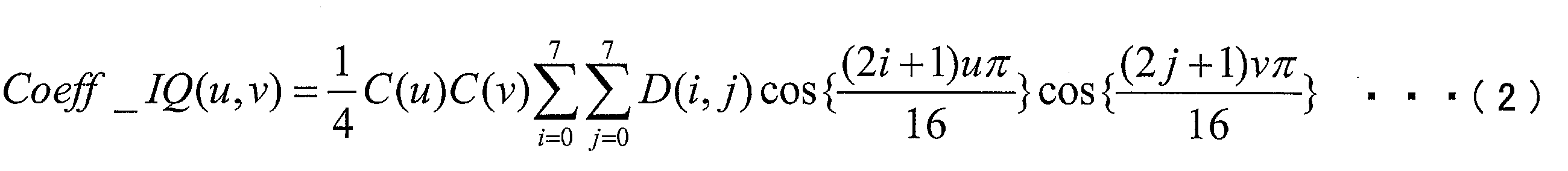
・C(u)=1 (u≠0)
・C(v)=1/√2 (v=0)
・C(v)=1 (v≠0)
(逆量子化・逆変換部23)
逆量子化・逆変換部23は、(1)量子化された変換係数Coeffを逆量子化し、(2)逆量子化によって得られた変換係数Coeff_IQに対して逆DCT(Discrete Cosine Transform)変換等の逆周波数変換を施し、(3)逆周波数変換によって得られた予測残差Dを加算器24に供給する。量子化された変換係数Coeffを逆量子化する際には、変換・量子化部22から供給された量子化ステップQPを利用する。なお、逆量子化・逆変換部23から出力される予測残差Dは、変換・量子化部22に入力される予測残差Dに量子化誤差が加わったものであるが、ここでは簡単のために共通の呼称を用いる。逆量子化・逆変換部23のより具体的な動作は、動画像復号装置1の備える逆量子化・逆変換部13とほぼ同様である。
加算器24は、予測方式制御部21dにて選択された予測画像Predを、逆量子化・逆変換部23にて生成された予測残差Dに加算することによって、(局所)復号画像Pを生成する。加算器24にて生成された(局所)復号画像Pは、ループフィルタ26に供給されると共にフレームメモリ25に格納され、イントラ予測における参照画像として利用される。
可変長符号符号化部27は、(1)変換・量子化部22から供給された量子化後の変換係数Coeff並びにΔqp、(2)予測方式制御部21dから供給された量子化パラメータPP(インター予測パラメータPP_Inter、および、イントラ予測パラメータPP_Intra)、(3)予測タイプ情報Pred_type、および、(4)ループフィルタ26から供給されたフィルタパラメータFPを可変長符号化することによって、符号化データ#1を生成する。
減算器28は、予測方式制御部21dにて選択された予測画像Predを、符号化対象画像から減算することによって、予測残差Dを生成する。減算器28にて生成された予測残差Dは、変換・量子化部22によって周波数変換及び量子化される。
ループフィルタ26は、(1)復号画像Pにおけるブロック境界、またはパーティション境界の周辺の画像の平滑化(デブロック処理)を行うデブロッキングフィルタ(DF:Deblocking Filter)としての機能と、(2)デブロッキングフィルタが作用した画像に対して、フィルタパラメータFPを用いて適応フィルタ処理を行う適応フィルタ(ALF:Adaptive Loop Filter)としての機能を有している。
量子化残差情報符号化部271は、量子化された変換係数Coeff(xC、yC)をコンテキスト適応型2値算術符号化(CABAC:(Context-based Adaptive Binary Arithmetic Coding))することによって、量子化残差情報QDを生成する。生成された量子化残差情報QDに含まれるシンタックスは、図4及び図5に示した各シンタックス、及びsignificant_coeffgroup_flagである。
図54は、量子化残差情報符号化部271の構成を示すブロック図である。図54に示すように、量子化残差情報符号化部271は、変換係数符号化部220及び算術符号符号化部230を備えている。
算術符号符号化部230は、変換係数符号化部220から供給される各Binをコンテキストを参照して符号化することによって量子化残差情報QDを生成するための構成であり、図54に示すように、コンテキスト記録更新部231及びビット符号化部232を備えている。
コンテキスト記録更新部231は、各コンテキストインデックスctxIdxによって管理されるコンテキスト変数CVを記録及び更新するための構成である。ここで、コンテキスト変数CVには、(1)発生確率が高い優勢シンボルMPS(most probable symbol)と、(2)その優勢シンボルMPSの発生確率を指定する確率状態インデックスpStateIdxとが含まれている。
ビット符号化部232は、コンテキスト記録更新部231に記録されているコンテキスト変数CVを参照し、変換係数符号化部220の備える各部から供給される各Binを符号化することによって量子化残差情報QDを生成する。また、符号化したBinの値はコンテキスト記録更新部231にも供給され、コンテキスト変数CVを更新するために参照される。
図54に示すように、変換係数符号化部220は、ラスト位置符号化部221、スキャン順テーブル格納部222、係数符号化制御部223、係数有無フラグ符号化部224、係数値符号化部225、符号化係数記憶部226、サブブロック係数有無フラグ227、及びシンタックス導出部228を備えている。
シンタックス導出部228は、変換係数Coeff(xC、yC)の各値を参照し、対象周波数領域におけるこれらの変換係数を特定するためのシンタックスlast_significant_coeff_x、last_significant_coeff_y、significant_coeff_flag、coeff_abs_level_greater1_flag、coeff_abs_level_greater2_flag、coeff_sign_flag、及びcoeff_abs_level_minus3の各値を導出する。導出された各シンタックスは、符号化係数記憶部226に供給される。また、導出されたシンタックスのうちlast_significant_coeff_x、last_significant_coeff_yは、係数符号化制御部223及びラスト位置符号化部221にも供給される。また、導出されたシンタックスのうちsignificant_coeff_flagは、係数有無フラグ符号化部224にも供給される。なお、各シンタックスが示す内容については上述したためここでは説明を省略する。
ラスト位置符号化部221は、シンタックス導出部228より供給されるシンタックスlast_significant_coeff_x、last_significant_coeff_yを示すBinを生成する。また、生成した各Binをビット符号化部232に供給する。また、シンタックスlast_significant_coeff_x及びlast_significant_coeff_yのBinを符号化するために参照されるコンテキストを指定するコンテキストインデックスctxIdxを、コンテキスト記録更新部231に供給する。
スキャン順テーブル格納部222には、処理対象のTU(ブロック)のサイズ、スキャン方向の種別を表すスキャンインデックス、及びスキャン順に沿って付与された周波数成分識別インデックスを引数として、処理対象の周波数成分の周波数領域における位置を与えるテーブルが格納されている。このようなスキャン順テーブルの一例としては、図4及び図5に示したScanOrderが挙げられる。
係数符号化制御部223は、量子化残差情報符号化部271の備える各部における符号化処理の順序を制御するための構成である。
ブロックサイズが所定のサイズ以下(例えば4×4成分、8×8成分等)である場合、係数符号化制御部223は、シンタックス導出部228より供給されるシンタックスlast_significant_coeff_x及びlast_significant_coeff_yを参照し、順スキャンに沿った最後の非0変換係数の位置を特定すると共に、特定した最後の非0変換係数の位置を起点とするスキャン順であって、スキャン順テーブル格納部222に格納されたスキャン順テーブルよって与えられるスキャン順の逆スキャン順に、各周波数成分の位置(xC、yC)を、係数有無フラグ符号化部に供給する。
ブロックサイズが所定のサイズよりも大きい場合、係数符号化制御部223は、シンタックス導出部228から供給されるシンタックスlast_significant_coeff_x及びlast_significant_coeff_yを参照し、順スキャンに沿った最後の非0変換係数の位置を特定すると共に、特定した最後の非0変換係数を含むサブブロックの位置を起点とするスキャン順であって、スキャン順テーブル格納部222に格納されたサブブロックスキャン順テーブルよって与えられるスキャン順の逆スキャン順に、各サブブロックの位置(xCG、yCG)を、サブブロック係数有無フラグ符号化部227に供給する。
係数値符号化部225は、シンタックス導出部228から供給されるシンタックスcoeff_abs_level_greater1_flag、coeff_abs_level_greater2_flag、coeff_sign_flag、及びcoeff_abs_level_minus3を示すBinを生成する。また、生成した各Binをビット符号化部232に供給する。また、これらのシンタックスのBinを符号化するために参照されるコンテキストを指定するコンテキストインデックスctxIdxを、コンテキスト記録更新部231に供給する。
本実施形態に係る係数有無フラグ符号化部224は、各位置(xC、yC)によって指定されるシンタックスsignificant_coeff_flag[xC][yC]を符号化する。より具体的には、各位置(xC、yC)によって指定されるシンタックスsignificant_coeff_flag[xC][yC]を示すBinを生成する。生成された各Binは、ビット符号化部232に供給される。また、係数有無フラグ符号化部224は、算術符号符号化部230にてシンタックスsignificant_coeff_flag[xC][yC]のBinを符号化するために用いられるコンテキストを決定するためのコンテキストインデックスctxIdxを算出する。算出されたコンテキストインデックスctxIdxは、コンテキスト記録更新部231に供給される。
周波数分類部224aは、対象となる周波数領域のサイズが所定のサイズ以下のサイズである場合(例えば、4×4成分、8×8成分である場合)、当該所定サイズ以下の周波数領域の各周波数成分に対して、その周波数成分の位置に応じて、当該周波数成分を複数の部分領域の何れかに分類すると共に、位置コンテキスト導出部224bによって導出されたコンテキストインデックスctxIdxを割り付ける。
位置コンテキスト導出部224bは、対象周波数成分に対するコンテキストインデックスctxIdxを、周波数領域における当該対象周波数成分の位置に基づいて導出する。
周辺参照コンテキスト導出部224cは、符号化対象の周波数成分に対するコンテキストインデックスctxIdxを、当該周波数成分の周辺の周波数成分について符号化済みの非0変換係数の数cntに基づいて導出する。
係数有無フラグ設定部224eは、シンタックス導出部228から供給されるシンタックスsignificant_coeff_flag[xC][yC]を示すBinを生成する。生成したBinは、ビット符号化部232に供給される。また、係数有無フラグ設定部224eは、対象サブブロックに含まれるsignificant_coeff_flag[xC][yC]の値を参照し、対象サブブロックに含まれる全てのsignificant_coeff_flag[xC][yC]が0である場合、すなわち、当該対象サブブロックに非0変換係数が含まれていない場合に、当該対象サブブロックに関するsignificant_coeffgroup_flag[xCG][yCG]の値を0に設定し、そうでない場合に当該対象サブブロックに関するsignificant_coeffgroup_flag[xCG][yCG]の値を1に設定する。このように値が付されたsignificant_coeffgroup_flag[xCG][yCG]は、サブブロック係数有無フラグ符号化部227に供給される。
係数有無フラグ記憶部224dには、シンタックスsignificant_coeff_flag[xC][yC]の各値が格納される。係数有無フラグ記憶部224dに格納されたシンタックスsignificant_coeff_flag[xC][yC]の各値は、周辺参照コンテキスト導出部224cによって参照される。
サブブロック係数有無フラグ符号化部227は、各サブブロック位置(xCG、yCG)によって指定されるシンタックスsignificant_coeffgroup_flag[xCG][yCG]を符号化する。より具体的には、各サブブロック位置(xCG、yCG)によって指定されるシンタックスsignificant_coeffgroup_flag[xCG][yCG]を示すBinを生成する。生成された各Binは、ビット符号化部232に供給される。また、サブブロック係数有無フラグ符号化部227は、算術符号符号化部230にてシンタックスsignificant_coeff_flag[xC][yC]のBinを符号化するために用いられるコンテキストを決定するためのコンテキストインデックスctxIdxを算出する。算出されたコンテキストインデックスctxIdxは、コンテキスト記録更新部231に供給される。
サブブロック係数有無フラグ符号化部227の備えるコンテキスト導出部227aは、各サブブロック位置(xCG、yCG)によって指定されるサブブロックに割り付けるコンテキストインデックスを導出する。サブブロックに割り付けられたコンテキストインデックスは、当該サブブロックについてのシンタックスsignificant_coeffgroup_flagを示すBinを復号する際に用いられる。また、コンテキストインデックスを導出する際には、サブブロック係数有無フラグ記憶部227bに記憶されたサブブロック係数有無フラグの値が参照される。コンテキスト導出部227aは、導出したコンテキストインデックスをコンテキスト記録更新部231に供給する。
サブブロック係数有無フラグ記憶部227bには、係数有無フラグ符号化部224から供給されたシンタックスsignificant_coeffgroup_flagの各値が記憶されている。サブブロック係数有無フラグ設定部227cは、隣接サブブロックに割り付けられたシンタックスsignificant_coeffgroup_flagを、サブブロック係数有無フラグ記憶部227bから読み出すことができる。
サブブロック係数有無フラグ設定部227cは、サブブロック係数有無フラグ設定部227cは、係数有無フラグ符号化部224から供給されるシンタックスsignificant_coeffgroup_flag[xCG][yCG]を示すBinを生成する。生成したBinは、ビット符号化部232に供給される。
サブブロックスキャン順を指定するスキャンタイプが垂直方向優先スキャンである場合、サブブロック係数有無フラグ設定部227cは、図20(a)に示すように、サブブロック(xCG、yCG)に隣接するサブブロック(xCG、yCG+1)に割り付けられたサブブロック係数有無フラグsignificant_coeffgroup_flag[xCG][yCG+1]の値を参照する。significant_coeffgroup_flag[xCG][yCG+1]=1である場合、サブブロック係数有無フラグ設定部227cは、significant_coeffgroup_flag[xCG][yCG]=1であると推測し、significant_coeffgroup_flag[xCG][yCG]の符号化を省略する。
サブブロックスキャン順を指定するスキャンタイプが水平方向優先スキャンである場合、サブブロック係数有無フラグ設定部227cは、図20(b)に示すように、サブブロック(xCG、yCG)に隣接するサブブロック(xCG+1、yCG)に割り付けられたサブブロック係数有無フラグsignificant_coeffgroup_flag[xCG+1][yCG]の値を参照する。significant_coeffgroup_flag[xCG+1][yCG]=1である場合、サブブロック係数有無フラグ設定部227cは、significant_coeffgroup_flag[xCG][yCG]=1であると推測し、significant_coeffgroup_flag[xCG][yCG]の符号化を省略する。
サブブロックスキャン順を指定するスキャンタイプが斜め方向スキャンである場合、サブブロック係数有無フラグ設定部227cは、図20(c)に示すように、サブブロック(xCG、yCG)に隣接するサブブロック(xCG+1、yCG)に割り付けられたサブブロック係数有無フラグsignificant_coeffgroup_flag[xCG+1][yCG]の値とサブブロック(xCG、yCG+1)に割り付けられたサブブロック係数有無フラグsignificant_coeffgroup_flag[xCG][yCG+1]の値とを参照する。
本実施形態に係る係数有無フラグ符号化部は、上述の構成に限られるものではない。本実施形態に係る係数有無フラグ符号化部は、第1の変形例に係る係数有無フラグ復号部124’に対応する構成を有するものとしてもよい。
・係数有無フラグ符号化部224’は、サブブロック周辺参照コンテキスト導出部224fを備えている。
また、本実施形態に係る係数有無フラグ符号化部は、第2の変形例に係る係数有無フラグ復号部124’’に対応する構成を有するものとしてもよい。
また、本実施形態に係る係数有無フラグ符号化部224は、第3の変形例に係る係数有無フラグ復号部124に対応する構成を有するものとしてもよい。
導出方法制御部224xは、対象となるTUサイズが所定のサイズ以下のサイズである場合(例えば、4×4TU、8×8TUである場合)、当該所定サイズ以下の周波数領域の各周波数成分に対して、その周波数成分の位置に応じて、当該周波数成分を複数の部分領域の何れかに分類すると共に、位置コンテキスト導出部224bによって導出されたコンテキストインデックスctxIdxを割り付ける。
位置コンテキスト導出部224bは、対象周波数成分に対するコンテキストインデックスctxIdxを、周波数領域における当該対象周波数成分の位置に基づいて導出する。
周辺参照コンテキスト導出部224cは、符号化対象の周波数成分に対するコンテキストインデックスctxIdxを、当該周波数成分の周辺の周波数成分について符号化済みの非0変換係数の数cntに基づいて導出する。より具体的には、周辺参照コンテキスト導出部224cは、対象周波数成分の位置(xC,yC)、もしくは、対象周波数成分が属するサブブロックの位置(xCG,yCG)が所定の条件を満たす場合、変換係数の位置に応じて異なる参照位置(テンプレート)を用いて符号化済みの非0変換係数の数cntを導出する。
係数有無フラグ設定部224eは、シンタックス導出部228から供給されるシンタックスsignificant_coeff_flag[xC][yC]を示すBinを生成する。生成したBinは、ビット符号化部232に供給される。また、係数有無フラグ設定部224eは、対象サブブロックに含まれるsignificant_coeff_flag[xC][yC]の値を参照し、対象サブブロックに含まれる全てのsignificant_coeff_flag[xC][yC]が0である場合、すなわち、当該対象サブブロックに非0変換係数が含まれていない場合に、当該対象サブブロックに関するsignificant_coeff_group_flag[xCG][yCG]の値を0に設定し、そうでない場合に当該対象サブブロックに関するsignificant_coeff_group_flag[xCG][yCG]の値を1に設定する。このように値が付されたsignificant_coeff_group_flag[xCG][yCG]は、サブブロック係数有無フラグ符号化部227に供給される。
上述した動画像符号化装置2及び動画像復号装置1は、動画像の送信、受信、記録、再生を行う各種装置に搭載して利用することができる。なお、動画像は、カメラ等により撮像された自然動画像であってもよいし、コンピュータ等により生成された人工動画像(CGおよびGUIを含む)であってもよい。
上述した動画像復号装置1、および動画像符号化装置2の各ブロックは、集積回路(ICチップ)上に形成された論理回路によってハードウェア的に実現してもよいし、CPU(Central Processing Unit)を用いてソフトウェア的に実現してもよい。
X=log2TrafoWidth == 2 ? xC : xC>>1
Y=log2TrafoHeight == 2 ? yC : yC>>1
によって変数X及びYを導出し、該変数Xの下位1ビット目(上位2ビット目)の値と、該変数Xの下位2ビット目(上位1ビット目)の値と、該変数Yの下位1ビット目(上位2ビット目)の値と、該変数Yの下位2ビット目(上位1ビット目)の値とに基づいて定まる対象周波数成分の属するサブ領域の識別番号(相対コンテキストインデックス)と所定のオフセットを加算して、対象周波数成分のコンテキストインデックスを導出することを特徴としている。
X=log2TrafoSize ==2 ? xC : xC>>1
Y=log2TrafoSize ==2 ? yC : yC>>1
によって変数X及びYを導出し、
X=0かつY=0であるとき、対象周波数成分をサブ領域R0に分類し、
(X=0かつY=0)でなくX<2かつY<2であるとき、対象周波数成分をサブ領域R1に分類し、
X=2かつY<2であるとき、対象周波数成分をサブ領域R2へ分類し、
X=3かつY<2であるとき、対象周波数成分をサブ領域R3へ分類し、
X<2かつY=2であるとき、対象周波数成分をサブ領域R4へ分類し、
X<2かつY=3であるとき、対象周波数成分をサブ領域R5へ分類し、
X≧2かつY≧2であるとき、対象周波数成分をサブ領域R6へ分類する、ことが好ましい。
)と、該周波数領域の横幅を示す変数であるlog2TrafoWidth(log2TrafoWidthは自然数)と該周波数領域の縦幅を示す変数であるlog2TrafoHeight(log2TrafoHeightは自然数)に基づき、
X=log2TrafoWidth == 2 ? xC : xC>>2
Y=log2TrafoHeight == 2 ? yC : yC>>2
によって変数X及びYを導出し、
X=0かつY=0であるとき、対象周波数成分をサブ領域A0に分類し、
(X=0かつY=0)でなくX<2かつY<2であるとき、対象周波数成分をサブ領域A1に分類し、
X=2かつY<2であるとき、対象周波数成分をサブ領域A2へ分類し、
X=3かつY<2であるとき、対象周波数成分をサブ領域A3へ分類し、
X<2かつY=2であるとき、対象周波数成分をサブ領域A4へ分類し、
X<2かつY=3であるとき、対象周波数成分をサブ領域A5へ分類し、
X≧2かつY≧2であるとき、対象周波数成分をサブ領域A6へ分類する、ことが好ましい。
(1-a)xC<width/4、かつ、yC<height/4の場合、対象周波数成分をサブ領域R0へ分類する
(1-b)xC≧width/4、かつ、yC<height/4の場合、対象周波数成分をサブ領域R1へ分類する
(1-c)xC<width/4、かつ、yC≧height/4の場合、対象周波数成分をサブ領域R2へ分類する
(1-d)xC≧width/4、かつ、yC≧height/4の場合、対象周波数成分をサブ領域R3へ分類する
xC≧width/2、かつ、yC<height/2の場合、(2-a)~(2-b)の条件により、対象周波数成分をサブ領域R4、またはR5へ分類し、
(2-a)xC<width×3/4の場合、対象周波数成分をサブ領域R4へ分類する
(2-b)xC≧width×3/4の場合、対象周波数成分をサブ領域R5へ分類する
xC<width/2、かつ、yC≧height/2の場合、(3-a)~(3-b)の条件により、対象周波数成分をサブ領域R6、またはR7へ分類し、
(3-a)yC<height×3/4の場合、対象周波数成分をサブ領域R6へ分類する
(3-b)yC≧height×3/4の場合、対象周波数成分をサブ領域R7へ分類する
xC≧width/2、かつ、yC≧height/2の場合、対象周波数成分をサブ領域R8へ分類する、ことが好ましい。
(1-a)xC<width/4、かつ、yC<height/4の場合、対象周波数成分をサブ領域R0へ分類する
(1-b)xC≧width/4、または、yC≧height/4の場合、対象周波数成分をサブ領域R1へ分類する
xC≧width/2、かつ、yC<height/2の場合、(2-a)~(2-b)の条件により、対象周波数成分をサブ領域R2、またはR3へ分類し、
(2-a)xC<width×3/4の場合、対象周波数成分をサブ領域R2へ分類する
(2-b)xC≧width×3/4の場合、対象周波数成分をサブ領域R3へ分類する
xC<width/2、かつ、yC≧height/2の場合、(3-a)~(3-b)の条件により、対象周波数成分をサブ領域R4、またはR5へ分類し、
(3-a)yC<height×3/4の場合、対象周波数成分をサブ領域R4へ分類する
(3-b)yC≧height×3/4の場合、対象周波数成分をサブ領域R5へ分類する
xC≧width/2、かつ、yC≧height/2の場合、対象周波数成分をサブ領域R6へ分類する、ことが好ましい。
11 可変長符号復号部
111 量子化残差情報復号部(算術復号装置)
120 変換係数復号部
123 係数復号制御部(サブブロック分割手段、サブブロックスキャン順設定手段)
124 係数有無フラグ復号部(コンテキストインデックス導出手段)
124a 周波数分類部
124b 位置コンテキスト導出部
124c 周辺参照コンテキスト導出部
124d 係数有無フラグ記憶部
124e 係数有無フラグ設定部
124x 導出方法制御部
124z コンテキスト導出部
127 サブブロック係数有無フラグ復号部(サブブロック係数有無フラグ復号手段)
127a コンテキスト導出部
127b サブブロック係数有無フラグ記憶部
127c サブブロック係数有無フラグ設定部
130 算術符号復号部
131 コンテキスト記録更新部
132 ビット復号部(シンタックス復号手段)
2 動画像符号化装置(画像符号化装置)
27 可変長符号符号化部
271 量子化残差情報符号化部(算術符号化装置)
220 変換係数符号化部
223 係数符号化制御部(サブブロック分割手段、サブブロックスキャン順設定手段)
224 係数有無フラグ符号化部(コンテキストインデックス導出手段)
224a 周波数分類部
224b 位置コンテキスト導出部
224c 周辺参照コンテキスト導出部
224d 係数有無フラグ記憶部
224e 係数有無フラグ設定部
224x 導出方法制御部
224z コンテキスト導出部
227 サブブロック係数有無フラグ符号化部(サブブロック係数有無フラグ符号化手段)
227a コンテキスト導出部
227b サブブロック係数有無フラグ記憶部
227c サブブロック係数有無フラグ設定部
228 シンタックス導出部
230 算術符号符号化部
231 コンテキスト記録更新部
232 ビット符号化部(シンタックス符号化手段)
Claims (12)
- 対象画像の単位領域毎に符号化データを復号する算術復号装置において、
前記単位領域毎に2以上のサブブロックに分割された該サブブロック毎に、少なくとも1つの非0変換係数が含まれるか否かを示すサブブロック係数有無フラグを復号するサブブロック係数有無フラグ復号手段と、
変換係数が0であるか否かを示す変換係数有無フラグに基づいて、対象サブブロックのコンテキストインデックスを導出するコンテキストインデックス導出手段とを備え、
前記コンテキストインデックス導出手段は、前記対象サブブロックに隣接する隣接サブブロックの前記サブブロック係数有無フラグに応じて、前記対象サブブロックの前記コンテキストインデックスを導出することを特徴とする算術復号装置。 - 少なくとも2つの前記隣接サブブロックのサブブロック係数有無フラグの値が1の場合、
前記コンテキストインデックス導出手段は、前記対象サブブロックの前記変換係数有無フラグに対して、共通のコンテキストインデックスを導出することを特徴とする請求項1に記載の算術復号装置。 - 前記少なくとも2つの前記隣接サブブロックは、前記対象サブブロックに対して隣接右側のサブブロックと隣接下側のサブブロックであることを特徴とする請求項2に記載の算術復号装置。
- 前記対象サブブロックのコンテキストインデックスは、少なくとも2つの前記隣接サブブロックの前記サブブロック係数有無フラグに応じて異なることを特徴とする請求項1に記載の算術復号装置。
- 請求項1から4のいずれか一項に記載の算術復号装置と、
前記算術復号装置によって復号された前記変換係数を逆周波数変換することによって残差画像を生成する逆周波数変換手段と、
前記残差画像と、生成済みの復号画像から予測された予測画像とを加算することによって復号画像を生成する復号画像生成手段とを備えることを特徴とする画像復号装置。 - 対象画像の単位領域毎に符号化データを生成する算術符号化装置において、
前記単位領域毎に2以上のサブブロックに分割された該サブブロック毎に、少なくとも1つの非0変換係数が含まれるか否かを示すサブブロック係数有無フラグを符号化するサブブロック係数有無フラグ符号化手段と、
変換係数が0であるか否かを示す変換係数有無フラグに基づいて、対象サブブロックのコンテキストインデックスを導出するコンテキストインデックス導出手段とを備え、
前記コンテキストインデックス導出手段は、前記対象サブブロックに隣接する隣接サブブロックの前記サブブロック係数有無フラグに応じて、前記コンテキストインデックスを導出することを特徴とする算術符号化装置。 - 対象画像の単位領域毎に符号化データを復号する算術復号装置において、
変換係数が0であるか否かを示す変換係数有無フラグに基づいて、前記単位領域毎のコンテキストインデックスを導出するコンテキストインデックス導出手段と、
導出した前記コンテキストインデックスによって指定される確率状態に基づいて、前記変換係数有無フラグを算術復号するシンタックス復号手段とを備え、
前記コンテキストインデックス導出手段は、前記単位領域のサイズが異なる少なくとも2つの単位領域の低周波側に属する前記変換係数有無フラグに対し、共通のコンテキストインデックスを導出することを特徴とする算術復号装置。 - 前記変換係数有無フラグは、少なくとも輝度に関する変換係数有無フラグと、色差に関する変換係数有無フラグとを含み、
前記コンテキストインデックス導出手段は、前記輝度に関する変換係数有無フラグと前記色差に関する変換係数有無フラグそれぞれに対して、コンテキストインデックスを導出することを特徴とする請求項7に記載の算術復号装置。 - 前記コンテキストインデックス導出手段は、前記輝度に関する変換係数有無フラグに対し、共通のコンテキストインデックスを導出することを特徴とする請求項8に記載の算術復号装置。
- 前記コンテキストインデックス導出手段は、前記色差に関する変換係数有無フラグに対し、共通のコンテキストインデックスを導出することを特徴とする請求項8又は9に記載の算術復号装置。
- 請求項7から10のいずれか一項に記載の算術復号装置と、
前記算術復号装置によって復号された変換係数を逆周波数変換することによって残差画像を生成する逆周波数変換手段と、
前記残差画像と、生成済みの復号画像から予測された予測画像とを加算することによって復号画像を生成する復号画像生成手段とを備えることを特徴とする画像復号装置。 - 対象画像の単位領域毎に符号化データを生成する算術符号化装置において、
変換係数が0であるか否かを示す変換係数有無フラグに基づいて、前記単位領域毎のコンテキストインデックスを導出するコンテキストインデックス導出手段と、
導出した前記コンテキストインデックスによって指定される確率状態に基づいて、前記変換係数有無フラグを算術符号化するシンタックス符号化手段とを備え、
前記コンテキストインデックス導出手段は、前記単位領域のサイズが異なる少なくとも2つの単位領域の低周波側に属する前記変換係数有無フラグに対し、共通のコンテキストインデックスを導出することを特徴とする算術符号化装置。
Priority Applications (7)
| Application Number | Priority Date | Filing Date | Title |
|---|---|---|---|
| RU2014130759A RU2628130C2 (ru) | 2011-12-28 | 2012-12-26 | Устройство арифметического декодирования, устройство декодирования изображения и устройство арифметического кодирования |
| CN201810673979.7A CN108900839B (zh) | 2011-12-28 | 2012-12-26 | 图像解码装置及方法、图像编码装置及方法 |
| CN201810673977.8A CN108769691B (zh) | 2011-12-28 | 2012-12-26 | 图像解码装置、图像解码方法以及图像编码装置 |
| US14/368,377 US10129548B2 (en) | 2011-12-28 | 2012-12-26 | Arithmetic decoding device, image decoding device, and arithmetic coding device |
| CN201280065204.2A CN104067614B (zh) | 2011-12-28 | 2012-12-26 | 算术解码装置、图像解码装置以及算术编码装置 |
| JP2013551716A JP6134651B2 (ja) | 2011-12-28 | 2012-12-26 | 算術復号装置、算術符号化装置および算術復号方法 |
| EP12863083.7A EP2800368B1 (en) | 2011-12-28 | 2012-12-26 | Arithmetic decoding device, arithmetic decoding method, and arithmetic coding device |
Applications Claiming Priority (8)
| Application Number | Priority Date | Filing Date | Title |
|---|---|---|---|
| JP2011289938 | 2011-12-28 | ||
| JP2011-289938 | 2011-12-28 | ||
| JP2012011555 | 2012-01-23 | ||
| JP2012-011555 | 2012-01-23 | ||
| JP2012031118 | 2012-02-15 | ||
| JP2012-031118 | 2012-02-15 | ||
| JP2012091444 | 2012-04-12 | ||
| JP2012-091444 | 2012-04-12 |
Publications (1)
| Publication Number | Publication Date |
|---|---|
| WO2013099892A1 true WO2013099892A1 (ja) | 2013-07-04 |
Family
ID=48697376
Family Applications (1)
| Application Number | Title | Priority Date | Filing Date |
|---|---|---|---|
| PCT/JP2012/083555 WO2013099892A1 (ja) | 2011-12-28 | 2012-12-26 | 算術復号装置、画像復号装置、および、算術符号化装置 |
Country Status (6)
| Country | Link |
|---|---|
| US (1) | US10129548B2 (ja) |
| EP (1) | EP2800368B1 (ja) |
| JP (2) | JP6134651B2 (ja) |
| CN (3) | CN104067614B (ja) |
| RU (1) | RU2628130C2 (ja) |
| WO (1) | WO2013099892A1 (ja) |
Cited By (11)
| Publication number | Priority date | Publication date | Assignee | Title |
|---|---|---|---|---|
| JP2015507430A (ja) * | 2012-01-13 | 2015-03-05 | クゥアルコム・インコーポレイテッドQualcomm Incorporated | ビデオコード化において変換係数データをコード化するためのコンテキストの決定 |
| JP2015507884A (ja) * | 2012-01-19 | 2015-03-12 | キヤノン株式会社 | 変換ユニットの残差係数に対する有意度マップを符号化および復号化する方法、装置、およびシステム |
| JP2015508619A (ja) * | 2012-01-20 | 2015-03-19 | ソニー株式会社 | 有意性マップ符号化の計算量低減 |
| US9736495B2 (en) | 2012-01-20 | 2017-08-15 | Canon Kabushiki Kaisha | Method, apparatus and system for encoding and decoding the significance map for residual coefficients of a transform unit |
| WO2018159526A1 (ja) * | 2017-03-03 | 2018-09-07 | シャープ株式会社 | 動画像符号化装置及び動画像復号装置 |
| JP2018157571A (ja) * | 2018-04-19 | 2018-10-04 | マイクロソフト テクノロジー ライセンシング,エルエルシー | 非変換符号化のためのスキャン順序 |
| WO2018190594A1 (ko) * | 2017-04-13 | 2018-10-18 | 엘지전자(주) | 비디오 신호를 엔트로피 인코딩, 디코딩하는 방법 및 장치 |
| CN109479132A (zh) * | 2016-04-29 | 2019-03-15 | 世宗大学校产学协力团 | 用于对图像信号进行编码和解码的方法和装置 |
| RU2785817C1 (ru) * | 2017-04-13 | 2022-12-13 | ЭлДжи ЭЛЕКТРОНИКС ИНК. | Способ и устройство для энтропийного кодирования и декодирования видеосигнала |
| JP2022553697A (ja) * | 2020-05-22 | 2022-12-26 | テンセント・アメリカ・エルエルシー | 静止ピクチャプロファイルの構文要素を用いたコーディング方法、システムおよびコンピュータプログラム |
| JP7441638B2 (ja) | 2019-12-06 | 2024-03-01 | 日本放送協会 | 符号化装置、復号装置、及びプログラム |
Families Citing this family (36)
| Publication number | Priority date | Publication date | Assignee | Title |
|---|---|---|---|---|
| CN107302705B (zh) | 2012-01-20 | 2020-09-18 | Ge视频压缩有限责任公司 | 从数据流解码具有变换系数级别的多个变换系数的装置 |
| TW201401891A (zh) | 2012-03-26 | 2014-01-01 | Jvc Kenwood Corp | 影像編碼裝置、影像編碼方法、影像編碼程式、送訊裝置、送訊方法、及送訊程式、以及影像解碼裝置、影像解碼方法、影像解碼程式、收訊裝置、收訊方法、及收訊程式 |
| ES2770609T3 (es) * | 2012-07-02 | 2020-07-02 | Samsung Electronics Co Ltd | Codificación por entropía de un vídeo y decodificación por entropía de un vídeo |
| US9538175B2 (en) * | 2012-09-26 | 2017-01-03 | Qualcomm Incorporated | Context derivation for context-adaptive, multi-level significance coding |
| WO2014154094A1 (en) * | 2013-03-26 | 2014-10-02 | Mediatek Inc. | Method of cross color intra prediction |
| US9336558B2 (en) * | 2013-09-27 | 2016-05-10 | Apple Inc. | Wavefront encoding with parallel bit stream encoding |
| US9781424B2 (en) * | 2015-01-19 | 2017-10-03 | Google Inc. | Efficient context handling in arithmetic coding |
| MX2018001540A (es) * | 2015-09-10 | 2018-05-17 | Samsung Electronics Co Ltd | Dispositivo de codificacion, dispositivo de decodificacion y metodo de codificacion y decodificacion para los mismos. |
| KR20170102806A (ko) * | 2016-03-02 | 2017-09-12 | 한국전자통신연구원 | 비디오 신호 부호화/복호화 방법 및 이를 위한 장치 |
| CN113411578B (zh) * | 2016-05-13 | 2024-04-12 | 夏普株式会社 | 图像解码装置及其方法、图像编码装置及其方法 |
| EP3270595A1 (en) * | 2016-07-15 | 2018-01-17 | Thomson Licensing | Method and apparatus for last coefficient coding for adaptive transform based video compression |
| WO2018190595A1 (ko) * | 2017-04-13 | 2018-10-18 | 엘지전자(주) | 비디오 신호를 엔트로피 인코딩, 디코딩하는 방법 및 장치 |
| JP6986868B2 (ja) * | 2017-06-19 | 2021-12-22 | キヤノン株式会社 | 画像符号化装置、画像復号装置、画像符号化方法、画像復号方法、プログラム |
| WO2019029951A1 (en) * | 2017-08-08 | 2019-02-14 | Thomson Licensing | METHOD AND APPARATUS FOR VIDEO ENCODING AND DECODING |
| US10484695B2 (en) | 2017-10-23 | 2019-11-19 | Google Llc | Refined entropy coding for level maps |
| CN115190296A (zh) * | 2017-12-28 | 2022-10-14 | 松下电器(美国)知识产权公司 | 编码装置、解码装置和存储介质 |
| MX2020009875A (es) * | 2018-03-29 | 2020-10-12 | Sony Corp | Aparato de procesamiento de imagen y metodo de procesamiento de imagen. |
| US10645381B2 (en) | 2018-04-30 | 2020-05-05 | Google Llc | Intra-prediction for smooth blocks in image/video |
| KR20240014624A (ko) * | 2018-09-23 | 2024-02-01 | 엘지전자 주식회사 | 비디오 신호의 부호화/복호화 방법 및 이를 위한 장치 |
| CN111083489B (zh) | 2018-10-22 | 2024-05-14 | 北京字节跳动网络技术有限公司 | 多次迭代运动矢量细化 |
| WO2020084476A1 (en) * | 2018-10-22 | 2020-04-30 | Beijing Bytedance Network Technology Co., Ltd. | Sub-block based prediction |
| EP3857879A4 (en) | 2018-11-12 | 2022-03-16 | Beijing Bytedance Network Technology Co., Ltd. | SIMPLIFICATION OF COMBINED INTER-INTRA PREDICTION |
| EP3709658A4 (en) | 2018-11-12 | 2021-03-10 | LG Electronics Inc. | HIGH-FREQUENCY RESET BASED TRANSFORMATION COEFFICIENT CODING PROCESS AND APPARATUS THEREFOR |
| WO2020098803A1 (en) * | 2018-11-15 | 2020-05-22 | Beijing Bytedance Network Technology Co., Ltd. | Harmonization between affine mode and other inter coding tools |
| JP7241870B2 (ja) | 2018-11-20 | 2023-03-17 | 北京字節跳動網絡技術有限公司 | 部分的な位置に基づく差分計算 |
| WO2020103870A1 (en) | 2018-11-20 | 2020-05-28 | Beijing Bytedance Network Technology Co., Ltd. | Inter prediction with refinement in video processing |
| US10939107B2 (en) | 2019-03-01 | 2021-03-02 | Sony Corporation | Embedded codec circuitry for sub-block based allocation of refinement bits |
| WO2020177756A1 (en) | 2019-03-06 | 2020-09-10 | Beijing Bytedance Network Technology Co., Ltd. | Size dependent inter coding |
| US20220174286A1 (en) * | 2019-03-08 | 2022-06-02 | Electronics And Telecommunications Research Institute | Image encoding/decoding method and apparatus, and recording medium for storing bitstream |
| CN113596447B (zh) * | 2019-03-09 | 2022-09-09 | 杭州海康威视数字技术股份有限公司 | 进行编码和解码的方法、解码端、编码端和系统 |
| ES2953235T3 (es) * | 2019-03-12 | 2023-11-08 | Lg Electronics Inc | Codificación de imágenes basada en transformadas |
| CN113647099B (zh) | 2019-04-02 | 2022-10-04 | 北京字节跳动网络技术有限公司 | 解码器侧运动矢量推导 |
| WO2020215338A1 (zh) * | 2019-04-26 | 2020-10-29 | 深圳市大疆创新科技有限公司 | 视频编解码的方法和装置 |
| CN113853791B (zh) * | 2019-05-19 | 2023-11-14 | 字节跳动有限公司 | 数字视频中的变换旁路编解码残差块 |
| KR102211000B1 (ko) * | 2019-06-21 | 2021-02-02 | 삼성전자주식회사 | 비디오 복호화 방법 및 장치, 비디오 부호화 방법 및 장치 |
| WO2021010680A1 (ko) * | 2019-07-12 | 2021-01-21 | 엘지전자 주식회사 | 변환에 기반한 영상 코딩 방법 및 그 장치 |
Family Cites Families (14)
| Publication number | Priority date | Publication date | Assignee | Title |
|---|---|---|---|---|
| GB9422738D0 (en) * | 1994-11-10 | 1995-01-04 | Univ Western Ontario | Context-based, adaptive, progressive, lossless compression of still continuous -tone images |
| CN1874509B (zh) * | 2001-09-14 | 2014-01-15 | 诺基亚有限公司 | 基于上下文的自适应二进制算术编码的方法和系统 |
| KR101129655B1 (ko) * | 2002-09-17 | 2012-03-28 | 블라디미르 세페르코빅 | 압축비가 높고 최소의 자원을 필요로 하는 고속 코덱 |
| US7724827B2 (en) | 2003-09-07 | 2010-05-25 | Microsoft Corporation | Multi-layer run level encoding and decoding |
| US7379608B2 (en) * | 2003-12-04 | 2008-05-27 | Fraunhofer-Gesellschaft Zur Foerderung Der Angewandten Forschung, E.V. | Arithmetic coding for transforming video and picture data units |
| KR100612015B1 (ko) * | 2004-07-22 | 2006-08-11 | 삼성전자주식회사 | 컨텍스트 적응형 이진 산술 부호화 방법 및 그 장치 |
| US8311119B2 (en) * | 2004-12-31 | 2012-11-13 | Microsoft Corporation | Adaptive coefficient scan order |
| RU2336661C2 (ru) * | 2005-04-19 | 2008-10-20 | Самсунг Электроникс Ко., Лтд. | Способ и устройство адаптивного выбора контекстной модели для кодирования по энтропии |
| US7751636B2 (en) * | 2005-09-23 | 2010-07-06 | Faraday Technology Corp. | Method for decoding transform coefficients corresponding to an image |
| CN101370138B (zh) * | 2007-08-17 | 2011-02-09 | 中国科学院计算技术研究所 | 一种h.264标准cavlc残差系数的解码方法 |
| WO2009031648A1 (ja) * | 2007-09-06 | 2009-03-12 | Nec Corporation | 映像符号化装置、映像復号装置、映像符号化方法、映像復号方法、映像符号化あるいは復号プログラム |
| KR101805531B1 (ko) * | 2009-06-07 | 2018-01-10 | 엘지전자 주식회사 | 비디오 신호의 디코딩 방법 및 장치 |
| US9154801B2 (en) * | 2010-09-30 | 2015-10-06 | Texas Instruments Incorporated | Method and apparatus for diagonal scan and simplified coding of transform coefficients |
| KR102071574B1 (ko) * | 2011-12-21 | 2020-01-30 | 선 페이턴트 트러스트 | 화상 부호화 방법, 화상 부호화 장치, 화상 복호화 방법, 화상 복호화 장치, 및 화상 부호화 복호화 장치 |
-
2012
- 2012-12-26 CN CN201280065204.2A patent/CN104067614B/zh active Active
- 2012-12-26 US US14/368,377 patent/US10129548B2/en active Active
- 2012-12-26 CN CN201810673977.8A patent/CN108769691B/zh active Active
- 2012-12-26 EP EP12863083.7A patent/EP2800368B1/en active Active
- 2012-12-26 JP JP2013551716A patent/JP6134651B2/ja active Active
- 2012-12-26 WO PCT/JP2012/083555 patent/WO2013099892A1/ja active Application Filing
- 2012-12-26 CN CN201810673979.7A patent/CN108900839B/zh active Active
- 2012-12-26 RU RU2014130759A patent/RU2628130C2/ru active
-
2017
- 2017-04-24 JP JP2017085594A patent/JP6441406B2/ja not_active Expired - Fee Related
Non-Patent Citations (9)
| Title |
|---|
| "A combined proposal from JCTVC-G366, JCTVC-G657, and JCTVC-G768 on context reduction of significance map coding with CABAC (JCTVC-G1015", JOINT COLLABORATIVE TEAM ON VIDEO CODING (JCT-VC) OF ITU-T SG16 WP3 AND ISO/IEC JTCL/SC29/WG117TH MEETING, 21 November 2011 (2011-11-21) |
| "CEll: Scanning Passes of Residual Data in HE (JCTVC-G320", JOINT COLLABORATIVE TEAM ON VIDEO CODING (JCT-VC) OF ITU-T SG16 WP3 AND ISO/IEC JTCL/SC29/WG117TH MEETING, 21 November 2011 (2011-11-21) |
| "High Efficiency Video Coding (HEVC) text specification draft 6 (JCTVC-H1003_dk", JOINT COLLABORATIVE TEAM ON VIDEO CODING (JCT-VC) OF ITU-T SG16 WP3 AND ISO/IEC JTCL/SC29 WG11 6TH MEETING, 1 February 2012 (2012-02-01) |
| "JCT-VC break-out report: Harmonization of NSQT with residual coding (JCTVC-Gl038", JOINT COLLABORATIVE TEAM ON VIDEO CODING (JCT-VC) OF ITU-T SG16 WP3 AND ISO/IEC JTC1/SC29/WG117TH MEETING, 21 November 2011 (2011-11-21) |
| "Multi level significance maps for Large Transform Units (JCTVC-G644", JOINT COLLABORATIVE TEAM ON VIDEO CODING (JCT-VC) OF ITU-T SG16 WP3 AND ISO/IEC JTCL/SC29/WG117TH MEETING, 21 November 2011 (2011-11-21) |
| "WD4: Working Draft 4 of High-Efficiency Video Coding (JCTVC-F803 d2", JOINT COLLABORATIVE TEAM ON VIDEO CODING (JCT-VC) OF ITU-T SG16 WP3 AND ISO/IEC JTC1/SC29/WG11 6TH.MEETING, 14 July 2011 (2011-07-14) |
| NGUYEN NGUYEN ET AL.: "Multi-level significance maps for Large Transform Units. Document JCTVC-G644", JOINT COLLABORATIVE TEAM ON VIDEO CODING (JCT-VC) OF ITU-T SG16 WP3 AND ISO/IEC JTC1/SC29/WG11 7TH MEETING, 21 November 2011 (2011-11-21) - 30 November 2011 (2011-11-30), GENEVA, XP055016838 * |
| See also references of EP2800368A4 |
| YINJI PIAO ET AL.: "Reduced chroma contexts for significance map coding in CABAC", JOINT COLLABORATIVE TEAM ON VIDEO CODING (JCT-VC) OF ITU-T SG16 WP3 AND ISO/IEC JTC1/SC29/WG11 7TH MEETING, 21 November 2011 (2011-11-21) - 30 November 2011 (2011-11-30), GENEVA, CH, XP030050915 * |
Cited By (27)
| Publication number | Priority date | Publication date | Assignee | Title |
|---|---|---|---|---|
| US9621894B2 (en) | 2012-01-13 | 2017-04-11 | Qualcomm Incorporated | Determining contexts for coding transform coefficient data in video coding |
| JP2015507430A (ja) * | 2012-01-13 | 2015-03-05 | クゥアルコム・インコーポレイテッドQualcomm Incorporated | ビデオコード化において変換係数データをコード化するためのコンテキストの決定 |
| JP2015507884A (ja) * | 2012-01-19 | 2015-03-12 | キヤノン株式会社 | 変換ユニットの残差係数に対する有意度マップを符号化および復号化する方法、装置、およびシステム |
| US9769484B2 (en) | 2012-01-19 | 2017-09-19 | Canon Kabushiki Kaisha | Method, apparatus and system for encoding and decoding the significance map for residual coefficients of a transform unit |
| JP2017184236A (ja) * | 2012-01-19 | 2017-10-05 | キヤノン株式会社 | 動画データを生成する方法、装置、プログラムおよび記憶媒体 |
| JP2017229097A (ja) * | 2012-01-19 | 2017-12-28 | キヤノン株式会社 | 動画データを生成する方法、装置、プログラムおよび記憶媒体 |
| US11025938B2 (en) | 2012-01-20 | 2021-06-01 | Sony Corporation | Complexity reduction of significance map coding |
| JP2015508619A (ja) * | 2012-01-20 | 2015-03-19 | ソニー株式会社 | 有意性マップ符号化の計算量低減 |
| JP2016105633A (ja) * | 2012-01-20 | 2016-06-09 | ソニー株式会社 | 有意性マップ符号化の計算量低減 |
| US9736495B2 (en) | 2012-01-20 | 2017-08-15 | Canon Kabushiki Kaisha | Method, apparatus and system for encoding and decoding the significance map for residual coefficients of a transform unit |
| JP2017192148A (ja) * | 2012-01-20 | 2017-10-19 | ソニー株式会社 | 有意性マップ符号化の計算量低減 |
| JP2017192147A (ja) * | 2012-01-20 | 2017-10-19 | ソニー株式会社 | 有意性マップ符号化の計算量低減 |
| US11140397B2 (en) | 2016-04-29 | 2021-10-05 | Industry Academy Cooperation Foundation Of Sejong University | Method and device for encoding and decoding image signal |
| US11122273B2 (en) | 2016-04-29 | 2021-09-14 | Industry Academy Cooperation Foundation Of Sejong University | Method and device for encoding and decoding image signal |
| CN109479132A (zh) * | 2016-04-29 | 2019-03-15 | 世宗大学校产学协力团 | 用于对图像信号进行编码和解码的方法和装置 |
| US11140396B2 (en) | 2016-04-29 | 2021-10-05 | Industry Academy Cooperation Foundation Of Sejong University | Method and device for encoding and decoding image signal |
| WO2018159526A1 (ja) * | 2017-03-03 | 2018-09-07 | シャープ株式会社 | 動画像符号化装置及び動画像復号装置 |
| RU2753238C1 (ru) * | 2017-04-13 | 2021-08-12 | ЭлДжи ЭЛЕКТРОНИКС ИНК. | Способ и устройство для энтропийного кодирования и декодирования видеосигнала |
| WO2018190594A1 (ko) * | 2017-04-13 | 2018-10-18 | 엘지전자(주) | 비디오 신호를 엔트로피 인코딩, 디코딩하는 방법 및 장치 |
| US11240536B2 (en) | 2017-04-13 | 2022-02-01 | Lg Electronics Inc. | Method and device for entropy encoding, decoding video signal |
| RU2768379C1 (ru) * | 2017-04-13 | 2022-03-24 | ЭлДжи ЭЛЕКТРОНИКС ИНК. | Способ и устройство для энтропийного кодирования и декодирования видеосигнала |
| RU2785817C1 (ru) * | 2017-04-13 | 2022-12-13 | ЭлДжи ЭЛЕКТРОНИКС ИНК. | Способ и устройство для энтропийного кодирования и декодирования видеосигнала |
| US11902592B2 (en) | 2017-04-13 | 2024-02-13 | Lg Electronics Inc. | Method and device for entropy encoding, decoding video signal |
| JP2018157571A (ja) * | 2018-04-19 | 2018-10-04 | マイクロソフト テクノロジー ライセンシング,エルエルシー | 非変換符号化のためのスキャン順序 |
| JP7441638B2 (ja) | 2019-12-06 | 2024-03-01 | 日本放送協会 | 符号化装置、復号装置、及びプログラム |
| JP2022553697A (ja) * | 2020-05-22 | 2022-12-26 | テンセント・アメリカ・エルエルシー | 静止ピクチャプロファイルの構文要素を用いたコーディング方法、システムおよびコンピュータプログラム |
| JP7391207B2 (ja) | 2020-05-22 | 2023-12-04 | テンセント・アメリカ・エルエルシー | 静止ピクチャプロファイルの構文要素を用いたコーディング方法、システムおよびコンピュータプログラム |
Also Published As
| Publication number | Publication date |
|---|---|
| EP2800368A1 (en) | 2014-11-05 |
| RU2628130C2 (ru) | 2017-08-15 |
| EP2800368B1 (en) | 2021-07-28 |
| JPWO2013099892A1 (ja) | 2015-05-07 |
| CN104067614B (zh) | 2018-07-27 |
| JP2017169209A (ja) | 2017-09-21 |
| JP6134651B2 (ja) | 2017-05-24 |
| US20140348247A1 (en) | 2014-11-27 |
| CN108900839B (zh) | 2022-05-31 |
| CN108769691B (zh) | 2022-05-31 |
| EP2800368A4 (en) | 2015-06-03 |
| CN108900839A (zh) | 2018-11-27 |
| RU2014130759A (ru) | 2016-02-20 |
| US10129548B2 (en) | 2018-11-13 |
| CN108769691A (zh) | 2018-11-06 |
| CN104067614A (zh) | 2014-09-24 |
| JP6441406B2 (ja) | 2018-12-19 |
Similar Documents
| Publication | Publication Date | Title |
|---|---|---|
| JP6134651B2 (ja) | 算術復号装置、算術符号化装置および算術復号方法 | |
| JP7001768B2 (ja) | 算術復号装置 | |
| JP6560702B2 (ja) | 算術復号装置、算術符号化装置、算術復号方法、および、算術符号化方法 | |
| JP7200320B2 (ja) | 画像フィルタ装置、フィルタ方法および動画像復号装置 | |
| JP6190361B2 (ja) | 算術復号装置、画像復号装置、算術符号化装置、および画像符号化装置 | |
| US10547861B2 (en) | Image decoding device | |
| WO2016203881A1 (ja) | 算術復号装置及び算術符号化装置 | |
| WO2016203981A1 (ja) | 画像復号装置及び画像符号化装置 | |
| WO2013105622A1 (ja) | 画像復号装置、画像符号化装置、および符号化データのデータ構造 | |
| JP2013192118A (ja) | 算術復号装置、画像復号装置、算術符号化装置、および画像符号化装置 | |
| JP2013187869A (ja) | 算術復号装置、算術符号化装置、画像復号装置、および画像符号化装置 | |
| JP2013141094A (ja) | 画像復号装置、画像符号化装置、画像フィルタ装置、および符号化データのデータ構造 | |
| WO2012137890A1 (ja) | 画像フィルタ装置、復号装置、符号化装置、および、データ構造 | |
| WO2012121352A1 (ja) | 動画像復号装置、動画像符号化装置、および、データ構造 | |
| JP2013118424A (ja) | 画像復号装置、画像符号化装置、および符号化データのデータ構造 | |
| JP2013223051A (ja) | 算術復号装置、画像復号装置、算術符号化装置、および画像符号化装置 | |
| WO2012081706A1 (ja) | 画像フィルタ装置、フィルタ装置、復号装置、符号化装置、および、データ構造 | |
| WO2019139012A1 (ja) | 画像フィルタ装置、画像復号装置、画像符号化装置、およびデータ構造 | |
| JP2013251827A (ja) | 画像フィルタ装置、画像復号装置、画像符号化装置、およびデータ構造 |
Legal Events
| Date | Code | Title | Description |
|---|---|---|---|
| 121 | Ep: the epo has been informed by wipo that ep was designated in this application |
Ref document number: 12863083 Country of ref document: EP Kind code of ref document: A1 |
|
| ENP | Entry into the national phase |
Ref document number: 2013551716 Country of ref document: JP Kind code of ref document: A |
|
| WWE | Wipo information: entry into national phase |
Ref document number: 14368377 Country of ref document: US |
|
| NENP | Non-entry into the national phase |
Ref country code: DE |
|
| WWE | Wipo information: entry into national phase |
Ref document number: 2012863083 Country of ref document: EP |
|
| ENP | Entry into the national phase |
Ref document number: 2014130759 Country of ref document: RU Kind code of ref document: A |