WO2013094892A1 - 단말의 pdsch a/n 전송 방법, 단말, 기지국의 pdsch a/n 수신 방법, 및 기지국 - Google Patents
단말의 pdsch a/n 전송 방법, 단말, 기지국의 pdsch a/n 수신 방법, 및 기지국 Download PDFInfo
- Publication number
- WO2013094892A1 WO2013094892A1 PCT/KR2012/010292 KR2012010292W WO2013094892A1 WO 2013094892 A1 WO2013094892 A1 WO 2013094892A1 KR 2012010292 W KR2012010292 W KR 2012010292W WO 2013094892 A1 WO2013094892 A1 WO 2013094892A1
- Authority
- WO
- WIPO (PCT)
- Prior art keywords
- pdsch
- downlink subframe
- subframe
- downlink
- allocated
- Prior art date
- Legal status (The legal status is an assumption and is not a legal conclusion. Google has not performed a legal analysis and makes no representation as to the accuracy of the status listed.)
- Ceased
Links
Images




Classifications
-
- H—ELECTRICITY
- H04—ELECTRIC COMMUNICATION TECHNIQUE
- H04L—TRANSMISSION OF DIGITAL INFORMATION, e.g. TELEGRAPHIC COMMUNICATION
- H04L1/00—Arrangements for detecting or preventing errors in the information received
- H04L1/004—Arrangements for detecting or preventing errors in the information received by using forward error control
- H04L1/0076—Distributed coding, e.g. network coding, involving channel coding
- H04L1/0077—Cooperative coding
-
- H—ELECTRICITY
- H04—ELECTRIC COMMUNICATION TECHNIQUE
- H04L—TRANSMISSION OF DIGITAL INFORMATION, e.g. TELEGRAPHIC COMMUNICATION
- H04L5/00—Arrangements affording multiple use of the transmission path
- H04L5/003—Arrangements for allocating sub-channels of the transmission path
- H04L5/0053—Allocation of signalling, i.e. of overhead other than pilot signals
- H04L5/0055—Physical resource allocation for ACK/NACK
-
- H—ELECTRICITY
- H04—ELECTRIC COMMUNICATION TECHNIQUE
- H04L—TRANSMISSION OF DIGITAL INFORMATION, e.g. TELEGRAPHIC COMMUNICATION
- H04L1/00—Arrangements for detecting or preventing errors in the information received
- H04L1/12—Arrangements for detecting or preventing errors in the information received by using return channel
- H04L1/16—Arrangements for detecting or preventing errors in the information received by using return channel in which the return channel carries supervisory signals, e.g. repetition request signals
-
- H—ELECTRICITY
- H04—ELECTRIC COMMUNICATION TECHNIQUE
- H04L—TRANSMISSION OF DIGITAL INFORMATION, e.g. TELEGRAPHIC COMMUNICATION
- H04L1/00—Arrangements for detecting or preventing errors in the information received
- H04L1/12—Arrangements for detecting or preventing errors in the information received by using return channel
- H04L1/16—Arrangements for detecting or preventing errors in the information received by using return channel in which the return channel carries supervisory signals, e.g. repetition request signals
- H04L1/18—Automatic repetition systems, e.g. Van Duuren systems
- H04L1/1829—Arrangements specially adapted for the receiver end
- H04L1/1854—Scheduling and prioritising arrangements
-
- H—ELECTRICITY
- H04—ELECTRIC COMMUNICATION TECHNIQUE
- H04L—TRANSMISSION OF DIGITAL INFORMATION, e.g. TELEGRAPHIC COMMUNICATION
- H04L27/00—Modulated-carrier systems
- H04L27/26—Systems using multi-frequency codes
- H04L27/2601—Multicarrier modulation systems
- H04L27/2602—Signal structure
-
- H—ELECTRICITY
- H04—ELECTRIC COMMUNICATION TECHNIQUE
- H04L—TRANSMISSION OF DIGITAL INFORMATION, e.g. TELEGRAPHIC COMMUNICATION
- H04L5/00—Arrangements affording multiple use of the transmission path
- H04L5/0001—Arrangements for dividing the transmission path
-
- H—ELECTRICITY
- H04—ELECTRIC COMMUNICATION TECHNIQUE
- H04L—TRANSMISSION OF DIGITAL INFORMATION, e.g. TELEGRAPHIC COMMUNICATION
- H04L5/00—Arrangements affording multiple use of the transmission path
- H04L5/0001—Arrangements for dividing the transmission path
- H04L5/0003—Two-dimensional division
- H04L5/0005—Time-frequency
- H04L5/0007—Time-frequency the frequencies being orthogonal, e.g. OFDM(A) or DMT
- H04L5/001—Time-frequency the frequencies being orthogonal, e.g. OFDM(A) or DMT the frequencies being arranged in component carriers
-
- H—ELECTRICITY
- H04—ELECTRIC COMMUNICATION TECHNIQUE
- H04L—TRANSMISSION OF DIGITAL INFORMATION, e.g. TELEGRAPHIC COMMUNICATION
- H04L5/00—Arrangements affording multiple use of the transmission path
- H04L5/14—Two-way operation using the same type of signal, i.e. duplex
- H04L5/1469—Two-way operation using the same type of signal, i.e. duplex using time-sharing
-
- H—ELECTRICITY
- H04—ELECTRIC COMMUNICATION TECHNIQUE
- H04L—TRANSMISSION OF DIGITAL INFORMATION, e.g. TELEGRAPHIC COMMUNICATION
- H04L5/00—Arrangements affording multiple use of the transmission path
- H04L5/003—Arrangements for allocating sub-channels of the transmission path
- H04L5/0058—Allocation criteria
- H04L5/0062—Avoidance of ingress interference, e.g. ham radio channels
Definitions
- the present invention relates to a system in which a base station and a terminal communicate with each other in a time division duplex (TDD) scheme with different configurations in interband.
- TDD time division duplex
- LTE Long Term Evolution
- LTE-A Long Term Advanced
- 3GPP series High-speed and large-capacity communication systems that can transmit and receive various data such as video and wireless data, beyond voice-oriented services. Therefore, there is a demand for developing a technology capable of transmitting a large amount of data corresponding to a wired communication network.
- a method of efficiently transmitting data through a plurality of CCs may be used.
- TDD time division duplex
- data may be transmitted and received by dividing transmission (Tx) and reception (Reception, Rx) into time slots using specific frequency bands.
- Tx transmission
- Rx reception
- the timing of transmitting response information for data reception may be changed according to a method of configuring uplink (UL) and downlink (DL) in the TDD system.
- carrier aggregation carrier aggregation, or carrier combining, "CA"
- CA carrier combining, or carrier combining, "CA”
- the band to which each component carrier belongs may be different. have. That is, when carrier combining is performed in an interband manner, when the TDD settings of the respective bands are different, it is necessary to consider at what timing to transmit response information for data reception. In addition, consideration should be given to which resource response information should be allocated at that timing. Timing and resource allocation to transmit response information for data reception should be applicable to both the full-duplex mode and the half-duplex mode.
- An object of the present invention is to provide a method and apparatus for determining a resource to which response information for data reception is allocated when a TDD configuration of two CCs in a multicarrier aggregation environment is different.
- At least one first associated downlink subframe determined based on a time division duplex (TDD) configuration set in a primary cell for a specific uplink subframe, and the specific uplink Determine at least one second associated downlink subframe determined based on the reference TDD setting selected based on the TDD settings of the primary cell and the secondary cell for the link subframe, and wherein the first associated downlink subframe is determined.
- TDD time division duplex
- a resource to which an A / N (Ack / Nack) of a physical downlink shared channel (PDSCH) received in the first downlink subframe is allocated is determined based on a TDD configuration configured in the primary cell. Doing; In the specific uplink subframe, a resource to which an A / N of a PDSCH received in a second downlink subframe other than the first downlink subframe among the second associated downlink subframes is allocated, is allocated to the first downlink subframe.
- the reception unit for receiving a PDSCH Physical Downlink Shared Channel
- At least one first associated downlink subframe determined based on a time division duplex (TDD) configuration set in a primary cell for a specific uplink subframe, and a primary cell for the specific uplink subframe Determine at least one second associative downlink subframe determined based on the reference TDD configuration selected based on the TDD configuration of the secondary cell and the second associative downlink subframe; Compare frames to search for at least one first downlink subframe that is the same downlink subframe, and A / N of the PDSCH received in the first downlink subframe in the specific uplink subframe (Ack / Nack) This allocated resource is determined based on the TDD configuration set in the primary cell, and is determined in the specific uplink subframe.
- TDD time division duplex
- PDSCH A / received in the first downlink subframe includes resources to which the A / N of the PDSCH received in the second downlink subframe other than the first downlink subframe among the second associated downlink subframes is allocated.
- a control unit for determining an N other than the allocated resource;
- a transmitter for mapping and transmitting PDSCH A / N to resources allocated to the PDSCH A / N received in the first downlink subframe and resources allocated to the PDSCH A / N received in the second downlink subframe. It provides a terminal comprising a.
- PDSCH Physical Downlink Shared Channel
- Ack / Nack Physical Downlink Shared Channel
- TDD time division duplex
- a second downlink subframe other than the first downlink subframe among at least one downlink subframe related to the specific uplink subframe determined based on a reference TDD configuration of a terminal communicating using a plurality of CCs It provides a PDSCH A / N reception method of the base station comprising the step of extracting the PDSCH A / N.
- a receiver for receiving a physical downlink shared channel (PDSCH) A / N (Ack / Nack) on a specific uplink subframe in a specific component carrier; And extracting PDSCH A / N of at least one first downlink subframe related to the specific uplink subframe determined based on a time division duplex (TDD) configuration of the specific component carrier and using a plurality of component carriers. Extracting PDSCH A / N of a second downlink subframe other than the first downlink subframe among at least one downlink subframe related to the specific uplink subframe determined based on a reference TDD configuration of a communicating terminal It provides a base station comprising a control unit.
- PDSCH physical downlink shared channel
- a / N Ack / Nack
- the present invention described above when the TDD configuration of the two CCs in the multi-carrier aggregation environment is different, it is possible to determine the resource to transmit the response information for the data reception.
- FIG. 1 illustrates a wireless communication system to which embodiments of the present invention can be applied.
- FIG 2 illustrates an interband CA environment according to an embodiment of the present specification.
- FIG 3 shows an example in which different TDD settings are required in an interband to avoid interference with other TDD systems.
- FIG. 4 is a diagram illustrating an operation method for each subframe when the terminal is in the half-duplex mode in the inter-band CA environment of FIG. 2.
- FIG. 5 is a diagram illustrating an operation method for each subframe when the UE is in full-duplex mode in the inter-band CA environment of FIG. 2.
- FIG. 6 is a diagram illustrating a PDSCH A / N transmission scheme according to a reference TDD configuration.
- FIG. 7 illustrates a PDSCH A / N transmission method of an interband CA terminal according to an embodiment.
- FIG. 8 illustrates a PDSCH A / N reception method of a base station according to an embodiment.
- FIG. 9 is a block diagram illustrating a configuration of a terminal according to an embodiment.
- FIG. 10 is a block diagram illustrating a configuration of a base station according to an embodiment.
- FIG. 1 illustrates a wireless communication system to which embodiments of the present specification are applied.
- Wireless communication systems are widely deployed to provide various communication services such as voice and packet data.
- a wireless communication system includes a user equipment (UE) 10 and a base station 20 performing uplink and downlink communication with the terminal 10.
- UE user equipment
- base station 20 performing uplink and downlink communication with the terminal 10.
- the terminal 10 is a comprehensive concept of a terminal in a wireless communication.
- WCDMA Wideband Code Division Multiple Access
- UE User Equipment
- MS Mobile Station
- UT User Interface
- the base station 20 or cell generally refers to a station that communicates with the user terminal 10, and includes a base station (BS), a node-B (Node-B), and an evolved node-B (eNB). ), A sector, a site, a base transceiver system (BTS), an access point, an access node, and a relay node.
- BS base station
- Node-B node-B
- eNB evolved node-B
- a sector a site
- BTS base transceiver system
- an access point an access node
- relay node a relay node.
- the base station 20 or a cell is a generic term representing some areas or functions covered by a base station controller (BSC) in CDMA, a NodeB in WCDMA, an eNB or a sector (site) in LTE, and the like. It should be interpreted as meaning, and it means to cover all the various coverage areas such as megacell, macrocell, microcell, picocell, femtocell, radio resource head (RRH) and relay node communication range.
- BSC base station controller
- NodeB in WCDMA
- eNB a sector
- RRH radio resource head
- the user terminal 10 and the base station 20 are two transmitting and receiving entities used in implementing the technology or the technical idea described in the present specification and are used in a comprehensive sense and are not limited by the terms or words specifically referred to. Do not.
- the user terminal 10 and the base station 20 are two (uplink or downlink) transmission and reception subjects used in implementing the technology or the technical idea described in the present invention, which are used in a comprehensive sense and are specifically referred to terms or words. It is not limited by.
- the uplink (Uplink, UL, or uplink) refers to a method for transmitting data to the base station 20 by the user terminal 10
- the downlink (Downlink, DL, or downlink) is the base station 20 Means a method of transmitting data to the user terminal 10.
- one terminal 10 and one base station 20 are shown in FIG. 1, the present invention is not limited thereto. It is possible for one base station 20 to communicate with the plurality of terminals 10, and also for one terminal 10 to communicate with the plurality of base stations 20.
- CDMA Code Division Multiple Access
- TDMA Time Division Multiple Access
- FDMA Frequency Division Multiple Access
- OFDMA Orthogonal Frequency Division Multiple Access
- OFDM-FDMA OFDM-TDMA
- UMB Universal Mobile Broadband
- the uplink transmission and the downlink transmission may use a time division duplex (TDD) scheme that is transmitted using different times, or may use a frequency division duplex (FDD) scheme that is transmitted using different frequencies.
- TDD time division duplex
- FDD frequency division duplex
- the terminal 10 and the base station 20 may perform uplink and downlink wireless communication.
- one radio frame (radioframe) consists of 10 subframes, and one subframe consists of two slots.
- the radio frame has a length of 10 ms and the subframe has a length of 1.0 ms.
- the basic unit of data transmission is a subframe unit, and downlink or uplink scheduling is performed on a subframe basis.
- the base station 20 may perform downlink transmission to the terminal 10.
- the base station 20 may transmit a physical downlink shared channel (PDSCH) as a downlink data channel for unicast transmission.
- PDSCH physical downlink shared channel
- the base station 20 grants scheduling control for transmission on downlink control information such as scheduling required for reception of the PDSCH and on an uplink data channel (for example, a physical uplink shared channel (PUSCH)).
- PUSCH physical uplink shared channel
- Indicator for distinguishing a physical downlink control channel (PDCCH), a PDSCH and a region of the PDCCH as a downlink control channel used for transmitting downlink control information (DCI) including information Control of physical control format indicator channel (PCFICH) for transmission, physical HARQ indicator channel (PHICH) for transmission of hybrid automatic repeat request (HARQ) confirmation for uplink transmission
- DCI downlink control information
- PCFICH physical control format indicator channel
- PHICH physical HARQ indicator channel
- HARQ hybrid automatic repeat request
- the terminal 10 may perform uplink transmission to the base station 20.
- the terminal 10 may transmit a PUSCH as an uplink data channel.
- the terminal 10 requests resource allocation when transmitting data in HARQ acknowledgment (NACK) / negative ACK (NACK), channel status report, and uplink indicating whether the downlink transport block has been successfully received.
- NACK HARQ acknowledgment
- NACK negative ACK
- a physical uplink control channel (PUCCH) as an uplink control channel used for transmitting uplink control information (UCI) including a scheduling request may be transmitted.
- UCI uplink control information
- TDD downlink and uplink time points are divided. If various TDD configurations exist, these time points may also vary.
- Table 1 below shows the TDD configuration. It can be seen that each TDD configuration has a different UL-DL subframe transmission timing. This TDD setting is set cell-specific.
- the region denoted by D is downlink and the region denoted by U is uplink.
- S is a subframe (downlink-to-uplink switch-point periodicity) switched from downlink to uplink. For example, when the TDD UL-DL configuration is “1”, when the subframe number is 0, 4, 5, 9, the downlink subframe is used, and when the subframe number is 2, 3, 7, 8 If the uplink is a subframe and the subframe numbers 1 and 6 are subframes that are switched from downlink to uplink.
- the UE when using one of the TDD UL-DL configuration, the UE may know in advance at which time downlink and at what time. This information allows the terminal to predict and operate in advance.
- the response to the data transmission transmitted in downlink that is, A / N (Ack / Nack) for PDSCH, is transmitted from the terminal 10 to the base station 20 through an uplink subframe.
- a / N information on a PDSCH transmitted in several downlink subframes may be transmitted in one uplink subframe.
- the number of downlink subframes associated with each uplink subframe is defined as M.
- a downlink-related set index (K: ⁇ k 0 , k 1 ,... k M-1 ⁇ ) indicating which downlink subframe is transmitted through which downlink subframe is transmitted is as follows. It may be as shown in Table 2.
- the PUCCH resource is expressed by Equation 1 below.
- M is the number of downlink subframes associated with the uplink subframe n, and 0 ⁇ i ⁇ M-1.
- c is selected from ⁇ 0, 1, 2, 3 ⁇ , Satisfies the ego, Is the number of downlink resource blocks, Is the number of subcarriers (eg, 12) in the resource block, Is the number of the first CCE (control channel elements) used for transmission of the corresponding PDCCH in the subframe (nk i ).
- PUCCH format 1 / 1a / 1b resource reserved for SR (Scheduling Request) transmission PUCCH format 1 / 1a / 1b resource indicated by Acknowledgment Resource Indication (ARI), reserved for Semi-Persistent Scheduling (SPS) transmission
- PUCCH format 1 / 1a / 1b may be transmitted using a PUCCH format 1 / 1a / 1b resource, etc.
- the system bandwidth is 10 MHz (50 Physical Resource Block (PRB)), Assume the case of (SR, ARI, SPS, etc. not transmitted).
- PRB Physical Resource Block
- n c 0 when CCE is 0 ⁇ 10 Is 0 to 10.
- n when CCE is 11 ⁇ 26, c 1 Is 11-26.
- n when CCE is 27 ⁇ 43 c 2 Is 27-43.
- n CCE is 44 ⁇ 60 c 3 Is 44-60.
- cCE 0 ⁇ 10
- i 1 Is 11-21.
- cCE 11 ⁇ 26
- i 1 Is 38-53.
- cCE 27 ⁇ 43
- i 1 Is 71-87.
- cCE 0 ⁇ 10
- cCE 11 ⁇ 26
- i 1 Is 49 to 64
- i 2 Is 65 to 80.
- CCE 27 ⁇ 43
- i 1 Is 98 ⁇ 114
- i 2 Is 115-131.
- cCE 44 ⁇ 60
- i 1 Is 149-165
- i 2 Is 166-182.
- cCE 0 ⁇ 10
- i 3 Is 33-43.
- cCE 11 ⁇ 26
- i 1 Is 60 to 75
- i 2 Is 76 ⁇ 91
- i 3 Is 92-107.
- Tables 3 to 6 show examples when the value of M is 1 to 4, but M may have a value of 9 (up to the case of subframe 2 at the UL-DL setting of 5). However, when the UL-DL configuration is 5, only A / N bundling mode can be transmitted using PUCCH format 1a / 1b.
- a / N for PDSCH transmitted in several downlink subframes transmitted in one uplink subframe in a TDD system can be derived without collision.
- the above-described method may be used among a plurality of terminals using the same uplink subframe for PDSCH A / N transmission.
- bands to which each component carrier belongs may be different.
- the TDD configuration may be configured differently for each band.
- one terminal uses carriers included in these differently configured bands.
- such a terminal will be referred to as an interband CA terminal.
- FIG. 2 is a diagram illustrating an inter-band CA environment according to an embodiment of the present specification.
- CC1 211 is a carrier py with coverage of the signal transmitted from the eNB at high power
- CC2 212 is eNB at low power.
- a carrier having coverage of a signal transmitted from the. CC1 211 and CC2 212 may be included in different bands.
- the TDD UL-DL configuration of CC1 211 is shown in Table 1 as 1 shown in FIG. 2 and shown as “281”, and the CC2 212 TDD UL-DL configuration is shown as 2 in FIG. 2 as “282”. .
- CA configuration is possible for terminals in the CC2 (212) coverage.
- the hot spot area 215 may be configured as a CA environment of the CC1 211 and the CC2 212.
- An interband CA terminal communicating with a base station in a CA environment may perform communication through CCs having different TDD settings (eg, CC1 211 and CC2 212).
- TDD UL-DL configurations may be used in the inter-band for traffic adaptation purposes.
- a TDD system (eg, to avoid interference with other TDD systems (eg, TDS-CDMA 310, LTE 320) that coexist in the same band.
- the TDD uplink-downlink of the LTE-A 330 and 340 is configured, and thus, the TDD system may require different TDD UL-DL configurations in the inter-band. That is, in the example of FIG. 3, LTE-A 330 in band A 410 has a TDD UL-DL setting of “2” to avoid interference with TDS-CDMA 310, and band B 420.
- LTE-A 340 has a TDD UL-DL setting of "0" in order to avoid interference with the LTE 320, and thus LTE-A 330 and LTE-A 340 located in different bands
- the TDD UL-DL configuration may be different from each other.
- the uplink subframe may follow many TDD UL-DL configurations in the low frequency band, and the downlink subframe may follow the TDD UL-DL configurations in the high frequency band. This can help increase coverage.
- the transmission mode that the UE can support on a conflicting subframe that may be caused by different TDD settings between interbands is half-duplex or full-duplex.
- the operation method may be different for each subframe.
- FIG. 4 is a diagram illustrating an operation method for each subframe in the case of a half-duplex mode on a collision subframe that may occur due to different TDD settings configured between interbands in the interband CA environment of FIG. 2.
- a primary cell PCell
- SCell Secondary Cell
- TDD UL-DL configuration “2” a primary cell
- U is a subframe reserved for uplink transmission
- D is a subframe reserved for downlink transmission
- S is a special subframe switched from downlink transmission to uplink transmission.
- the PCell when subframe numbers 3 and 8, the PCell is set to uplink and the SCell is set to downlink.
- subframes different in uplink / downlink according to CC will be referred to as conflicting subframes.
- the terminal Since the terminal is in the half-duplex mode, at least one of an uplink subframe of the PCell or a downlink subframe of the SCell is operated as a muted subframe.
- the uplink subframe of the PCell when the subframe numbers are 3 and 8, the uplink subframe of the PCell is a subframe muted.
- the uplink control channel (PUCCH) including the A / N for the PDSCH (PDSCH A / N) may be transmitted only through the PCell.
- 'PDSCH A / N' is used as the same meaning as 'A / N for PDSCH'.
- the uplink subframe that transmits PDSCH A / N in the PCell is a muted subframe, it may occur that PDSCH A / N cannot be transmitted through this.
- PDSCH A / N may be transmitted when subframe numbers 2, 3, 7, and 8 are used.
- the uplink subframe of CC1 is a muted subframe when the subframe numbers are 3 and 8
- PDSCH A / which is transmitted to a downlink subframe having subframe number 9 through a subframe having subframe number 3 / N cannot be transmitted and a PDSCH A / N transmitted in a downlink subframe having a subframe number of 4 cannot be transmitted through a subframe having a subframe number of 8.
- FIG. 5 is a diagram illustrating an operation method for each subframe when the UE is in full-duplex mode in the inter-band CA environment of FIG. 2.
- the PCell follows the TDD UL-DL configuration “1” and the SCell follows the TDD UL-DL configuration “2”.
- U is a subframe reserved for uplink transmission
- D is a subframe reserved for downlink transmission
- S is a special subframe switched from downlink transmission to uplink transmission.
- the PCell is set to uplink and the SCell is set to downlink. Since the UE is in full-duplex mode on a collision subframe that may occur due to different TDD settings set between interbands, the UE may simultaneously transmit an uplink signal through the PCell and a downlink signal through the SCell even on the collision subframe. Can be received.
- PUCCH including PDSCH A / N may be transmitted only through the PCell. However, a case may occur in which PDSCH A / N transmitted on a specific downlink subframe cannot be transmitted.
- PDSCH A / N transmitted through may be transmitted.
- the subframe number is 2, 3, 7, 8, the PDSCH A / N transmitted through the downlink subframe having the subframe number 0, 1, 4, 5, 6, or 9 is transmitted.
- the PDSCH may be transmitted in downlink. Can be.
- the timing of transmitting the PDSCH A / N is determined by the PCell. Although determined by the UL-DL configuration, the timing of transmitting PDSCH A / N is not set for the case where the subframe numbers are 3 and 8.
- a reference TDD configuration for PDSCH A / N transmission timing may be used.
- the reference TDD configuration includes (1) comparing two different TDD UL-DL configurations configured in the PCell and the SCell, and (2) searching for a common uplink subframe in the two TDD UL-DL configurations; (3) searching for one or more reference TDD settings belonging to the common uplink subframe by the uplink subframe that transmits PDSCH A / N, and (4) specific to the UE from one or more reference TDD settings. It may be obtained by the base station (and / or the terminal) through the step of selecting the reference TDD configuration. The reference TDD setting specific to the obtained terminal may be transmitted from the base station to the terminal through a downlink signal such as Radio Resource Control (RRC) or PDSCH. Or it may operate according to a predetermined rule.
- RRC Radio Resource Control
- the reference TDD setting is made by performing the steps (1) to (3) described above for all cases where the TDD UL-DL setting of the PCell and the TDD UL-DL setting of the SCell are different from each other. 7), (2 ') retrieving one or more reference TDD settings by applying the TDD UL-DL configuration of the PCell and the TDD UL-DL configuration of the SCell to Table 7, and (3') one or more reference TDDs It may be obtained by the base station (and / or terminal) through the step of selecting a reference TDD configuration specific to the terminal from the configuration.
- the reference TDD configuration specific to the obtained terminal may be transmitted from the base station to the terminal through a downlink signal such as RRC or PDSCH. Or it may operate according to a predetermined rule.
- the base station selects one of these values (for example, 1) as the reference TDD setting specific to the terminal.
- the base station transmits the selected reference TDD configuration information to the terminal. Or it is set to a specific value in advance on a specific basis.
- the uplink-downlink communication timing in the PCell CC0 follows the case of the TDD UL-DL configuration 0 in Table 1, and the uplink-downlink communication timing in the SCell CC1 is According to the case of TDD UL-DL configuration 1 in Table 1, the timing of PDSCH A / N transmission in the PCell (CC0) may follow the reference TDD configuration 1 in Table 2.
- FIG. 6 is a diagram illustrating PDSCH A / N transmission according to a reference TDD configuration.
- the TDD UL-DL configuration of the PCell CC0 of the first terminal is 0, the TDD UL-DL configuration of the SCell CC1 is 1, and FIG. A case where the TDD setting is 1 is shown.
- subframe 2 of PCell CC0 PDSCH A / N of subframes 5 and 6 of PCell CC0 and SCell CC1 may be transmitted.
- subframe 3 of PCell CC0 PDSCH A / N of subframe 9 of SCell CC1 may be transmitted. Since subframe 9 of the PCell CC0 is an uplink subframe, PDSCH A / N of subframe 9 of the PCell is not transmitted. If the UE is in the half-duplex mode and subframe 9 of the SCell is muted, PDSCH A / N of subframe 9 of the SCell may not be transmitted.
- subframe 7 of the PCell CC0 PDSCH A / N of subframes 0 and 1 of the PCell CC0 and the SCell CC1 may be transmitted.
- subframe 8 of the PCell CC0 A / N for the PDSCH transmitted in subframe 4 of the SCell CC1 may be transmitted. Since subframe 4 of the PCell CC0 is an uplink subframe, PDSCH A / N of subframe 4 of the PCell is not transmitted. If the UE is in the half-duplex mode and subframe 4 of the SCell is muted, PDSCH A / N of subframe 4 of the SCell may not be transmitted.
- a terminal using only one CC and not using CA technology may exist simultaneously.
- the terminal that does not use the CA technology may be a legacy terminal that cannot use the CA technology or a terminal that uses the CA technology but does not use the CA technology by setting.
- a legacy terminal for convenience of description, it will be referred to as a legacy terminal.
- the second terminal communicates with the base station using CC0, but does not use CC1.
- the second terminal communicates with the base station according to the TDD UL-DL configuration 0. That is, uplink-downlink communication timing follows TDD UL-DL configuration 0 in Table 1, and PDSCH A / N transmission follows TDD UL-DL configuration 0 in Table 2.
- PDSCH A / N of subframe 6 may be transmitted.
- PDSCH A / N of subframe 0 may be transmitted.
- PDSCH A / N of subframe 1 may be transmitted.
- PDSCH A / N of subframe 5 may be transmitted.
- the PUCCH resource to which the PDSCH A / N information is transmitted is May crash.
- the system bandwidth is 10MHz
- PUCCH resources of subframes 2 and 7 of the first terminal are allocated as shown in Table 4
- PUCCH resources of subframes 2 and 7 of the second terminal are allocated as shown in Table 3.
- Such a PUCCH collision may occur when the reference TDD configuration of the UE using CA technology is different from the TDD UL-DL configuration of the PCell. Highlighted in Table 8 below shows a case in which a PUCCH collision may occur.
- the PUCCH collision may occur even when the reference TDD settings of a plurality of terminals using CA technology are different.
- the PCell may be set identically and the SCell may be set differently, and in this case, the reference TDD settings may be different.
- the PCell and the SCell are set to be the same in the plurality of terminals, the reference TDD setting selected according to the environment of the terminal may be different. In this case, there is a possibility that a PUCCH collision occurs between a plurality of terminals.
- FIG. 7 illustrates a PDSCH A / N transmission method of an interband CA terminal according to an embodiment.
- the PDSCH A / N transmission method confirming TDD configuration information set in an interband CA terminal (S710) and comparing PDSCH A / N timing set in a legacy terminal and an interband CA terminal ( S720, searching for the same downlink subframe associated with the same uplink subframe specific to the legacy UE and the interband CA UE (S730), and for the same downlink subframe, using the equation 1 in PDSCH A / Allocating N resources (S740), Allocating PDSCH A / N resources by using a rule (Equation 2 to be described later) in the case of subframes other than the same downlink subframe (Equation 2 to be described later) S750) and transmitting the PDSCH A / N to the allocated resource (S760).
- S720 searching for the same downlink subframe associated with the same uplink subframe specific to the legacy UE and the interband CA UE (S730), and for the same downlink subframe, using the equation 1 in PDSCH A / Allocating N resources (S7
- the interband CA terminal checks the set TDD configuration information (S710).
- the TDD configuration information may include full-duplex mode or half-duplex mode configuration information, TDD UL-DL configuration information in the PCell and the SCell, reference TDD configuration information indicating PDSCH A / N transmission timing information, and the like.
- the reference TDD configuration information may be transmitted from the base station through RRC (Radio Resource Control) or PDCCH, and the interband CA terminal may receive the reference TDD configuration information to confirm the reference TDD configuration.
- a rule for selecting the reference TDD setting may be preset and shared between the base station and the interband CA terminal, and the interband CA terminal may check the reference TDD setting using a preset rule.
- the interband CA terminal compares PDSCH A / N timings set in the legacy terminal and the interband CA terminal (S720).
- the PDSCH A / N timing configured in the legacy terminal may be determined using the TDD UL-DL configuration set in the PCell and Table 2.
- the PDSCH A / N timing set in the interband CA terminal may be determined using the checked reference TDD configuration and Table 2.
- TDD UL-DL configuration is 0.
- K ⁇ 6 ⁇ (M is 1) in subframe 7
- the interband CA UE transmits PDSCH A / N, but the legacy UE does not transmit PDSCH A / N.
- the PUCCH resources do not collide. Therefore, in subframes 3 and 8, PUCCH resources may be allocated using Equation 1 described above.
- the interband CA terminal searches for the same downlink subframe associated with the same uplink subframe specific to the legacy terminal and the interband CA terminal (S730).
- the same downlink subframe is the same as the downlink subframe configured in the legacy terminal.
- Downlink communication may be performed on some resources of the special subframe S that is switched from downlink to uplink.
- the downlink subframe includes a special subframe S in addition to the downlink subframe D. Include.
- the TDD UL-DL configuration of the PCell is 0, the TDD UL-DL configuration of the SCell is 1, and the reference TDD configuration is 1, the legacy UE in subframe 2 is the A / N of the PDSCH transmitted in subframe 6.
- the interband CA terminal transmits the A / N of the PDSCH transmitted in subframes 5 and 6, the same downlink subframe associated with subframe 2 is subframe 6 (or n-6), and is not the same.
- the downlink subframe is 5 (or n-7).
- subframe 7 since the legacy terminal transmits the A / N of the PDSCH transmitted in subframe 1 and the interband CA terminal transmits the A / N of the PDSCH transmitted in subframes 0 and 1, the same downlink associated with subframe 6
- the link subframe is subframe 1 (or n-6) and non-identical downlink subframes are 0 (or n-7).
- the interband CA terminal allocates PDSCH A / N resources by using Equation 1 in the case of the same downlink subframe (S740).
- the value of M used in Equation 1 is determined by the TDD UL-DL configuration of the PCell (that is, the TDD UL-DL configuration of the legacy terminal).
- the TDD UL-DL configuration of the PCell is 0, the TDD UL-DL configuration of the SCell is 1, and the reference TDD configuration is 1, in the case of subframe 2, transmission is performed through subframe 6, which is the same downlink subframe.
- the PUCCH resource for PDSCH A / N of downlink subframe 6 of the interband CA UE transmitted in subframe 2 does not collide with the PUCCH resource for PDSCH A / N of downlink subframe 6 of the legacy UE.
- the PUCCH resource for PDSCH A / N of downlink subframe 1 of the interband CA terminal transmitted in subframe 7 does not collide with the PUCCH resource for PDSCH A / N of downlink subframe 1 of the legacy terminal. .
- the interband CA terminal allocates PDSCH A / N resources using a rule applied only to the interband CA terminal in the case of subframes other than the same downlink subframe (S750).
- the rule applied only to the interband CA terminal may be as shown in Equation 2 below.
- P is the number of remaining subframes other than the same downlink subframe among the downlink subframes associated with the uplink subframe.
- the number of PUCCH resources allocated to the same downlink subframe may be obtained by multiplying the value M by the same number of downlink subframes.
- the PUCCH resources for the PDSCH A / N obtained in step S740 and the PUCCH resources for the PDSCH A / N obtained in step S750 may be summarized in the following Tables 9 and 10, respectively.
- Table 9 is the same as Table 3 described above.
- PDSCH A / N of subframe 6 of an interband CA terminal transmitted in subframe 2 is allocated to PUCCH resources 0 to 60
- PDSCH A / N of subframe 5 is PUCCH resources 61 to 121. Is assigned to.
- the PDSCH A / N of subframe 1 of the interband CA terminal transmitted in subframe 7 is allocated to PUCCH resources 0 to 60
- the PDSCH A / N of subframe 0 is allocated to PUCCH resources 61 to 121.
- PDSCH A / N of subframe 6 of the legacy UE transmitted in subframe 2 is allocated to PUCCH resources 0 to 60, which does not collide with the PUCCH resource of the interband CA UE.
- the PDSCH A / N of subframe 1 of the legacy UE transmitted in subframe 7 is allocated to PUCCH resources 0 to 60, which does not collide with the PUCCH resource of the interband CA UE.
- the interband CA terminal transmits the PUCCH by allocating PDSCH A / N to resources obtained in steps S740 and S750 (S760).
- steps are described in the order of steps S750 and S760, but this is for convenience of description and may be executed in the order of steps S760 and S750, or the steps S750 and S760 may be simultaneously executed.
- FIG. 8 illustrates a PDSCH A / N reception method of a base station according to an embodiment.
- a PDSCH A / N reception method of a base station receiving a PUCCH transmitted by a terminal (S810), a legacy UE and an interband CA among downlink subframes related to an uplink subframe receiving the PUCCH.
- PDSCH A / N transmitted by the legacy terminal and PDSCH A / transmitted by the interband CA terminal from a region where PDSCH A / N of the same downlink subframe (that is, downlink subframe set in the legacy terminal) is allocated between the terminals.
- the base station receives the PUCCH through a specific uplink subframe (S810).
- the base station transmits the legacy terminal and the interband CA terminal from the region in which PDSCH A / N of the same downlink subframe is allocated between the legacy terminal and the interband CA terminal among the downlink subframes related to the specific uplink subframe.
- One PDSCH A / N is extracted (S820).
- the interband CA terminal uses the above-described reference TDD configuration, the same downlink subframe is the same as the downlink subframe configured in the legacy terminal.
- Equation 1 it can be known by using Equation 1 which PDSCH A / N is allocated to each PUCCH resource.
- the allocated resource region is a PDSCH A / N of the same downlink subframe implicitly (that is, a method of deriving PUCCH resources from the smallest CCE index to which the PDCCH indicating PDSCH transmission is transmitted)
- the PDSCH A / N transmitted by the legacy terminal and the interband CA terminal can be extracted.
- the PDSCH A / N transmitted by the interband CA terminal in this region is the A / N for the PDSCH received by the interband CA terminal through the same downlink subframe.
- the base station transmits a PDSCH transmitted by an interband CA terminal from a region in which PDSCH A / N of a downlink subframe that is not identical is allocated between a legacy terminal and an interband CA terminal among downlink subframes related to a specific uplink subframe. Extract A / N (S830).
- the interband CA terminal uses the above-described reference TDD configuration, the non-identical downlink subframe is a downlink subframe not configured in the legacy terminal or a downlink subframe additionally configured in the interband CA terminal.
- Equation 2 it is possible to know what PDSCH A / N is allocated to each PUCCH resource using Equation 2.
- a resource region to which PDSCH A / Ns of unequal downlink subframes are allocated As described above, the PDSCH A / N transmitted by the interband CA terminal can be extracted within this range.
- the PDSCH A / N transmitted by the interband CA terminal in this region is the A / N for the PDSCH received by the interband CA terminal through the same downlink subframe.
- steps are described in the order of steps S820 and S830, but this is for convenience of description, and may be performed in the order of steps S830 and S820, or the steps S820 and S830 may be simultaneously executed.
- FIG. 9 is a block diagram illustrating a configuration of a terminal according to an embodiment.
- the terminal 900 includes a receiver 910, a transmitter 920, and a controller 930.
- the terminal 900 illustrated in FIG. 9 is an interband CA terminal.
- the receiver 910 receives the PDSCH and the PDCCH in the configured downlink subframe.
- the downlink subframe may be determined based on the TDD UL-DL configuration and Table 1.
- the controller 930 performs steps S710 to S750 of FIG. 7 to allocate a PUCCH resource for the PDSCH A / N. That is, the controller 930 checks the reference TDD configuration, and identifies the PDSCH A / N transmission uplink subframe according to the TDD UL-DL configuration and the PDSCH A / N transmission uplink subframe according to the reference TDD configuration in the PCell.
- the same downlink subframe is found between the legacy UE and the interband CA UE among downlink subframes related to a specific uplink subframe transmitting PDSCH A / N, and the same downlink subframe is represented by Equation 1 below.
- Resource for PDSCH A / N is set, and resources for PDSCH A / N are set using Equation 2 for downlink subframes that are not identical.
- the transmitter 920 maps the PDSCH A / N to resources set by the controller 930 using Equations 1 and 2 in an uplink subframe determined by the reference TDD.
- FIG. 10 is a block diagram illustrating a configuration of a base station according to an embodiment.
- the base station 1000 includes a transmitter 1010, a receiver 1020, and a controller 1030.
- the transmitter 1010 transmits a PDSCH and a PDCCH in a configured downlink subframe.
- the downlink subframe may be determined based on the TDD UL-DL configuration and Table 1.
- the receiver 1020 receives the PDSCH A / N through the PUCCH in the configured uplink subframe.
- the timing of the PDSCH A / N transmitted from the legacy terminal may be determined based on the TDD UL-DL configuration and Table 2, and the timing of the PDSCH A / N transmitted from the interband CA terminal is based on the reference TDD configuration and Table 2 Can be determined.
- the controller 1030 uses the equation (1) from the region where the PDSCH A / N of the same downlink subframe is allocated between the legacy terminal and the interband CA terminal, and transmits the PDSCH A / N transmitted by the legacy terminal and the interband CA terminal.
- the PDSCH A / N transmitted by the interband CA terminal is extracted using Equation 2 from the region in which PDSCH A / N of the same downlink subframe is allocated between the legacy terminal and the interband CA terminal.
- the base station 1000 may check whether the terminal receives the PDSCH.
- the above embodiment may be applied to the case of the PUCCH format 1 / 1a / 1b for transmitting PDSCH A / N.
- PUCCH format 3 in a situation where only DAI (Downlink Assignment Index) is 1 in k m m K, PUCCH format 1a / 1b transmission may be used without using resources of PUCCH format 3.
Landscapes
- Engineering & Computer Science (AREA)
- Signal Processing (AREA)
- Computer Networks & Wireless Communication (AREA)
- Mobile Radio Communication Systems (AREA)
Abstract
본 발명은 기지국과 단말이 인터밴드(inter-band)에서 서로 다른 설정을 갖고 TDD(Time Division Duplex) 방식으로 통신하는 시스템에 관한 것이다.
Description
본 발명은 기지국과 단말이 인터밴드(inter-band)에서 서로 다른 설정을 갖고 TDD(Time Division Duplex) 방식으로 통신하는 시스템에 관한 것이다.
통신 시스템이 발전해나감에 따라 사업체들 및 개인들과 같은 소비자들은 매우 다양한 무선 단말기들을 사용하게 되었다. 현재의 3GPP 계열의 LTE(Long Term Evolution), LTE-A(LTE Advanced)등의 이동 통신 시스템에서는 음성 위주의 서비스를 벗어나 영상, 무선 데이터 등의 다양한 데이터를 송수신 할 수 있는 고속 대용량의 통신 시스템으로서, 유선 통신 네트워크에 준하는 대용량 데이터를 전송할 수 있는 기술 개발이 요구되고 있다. 대용량의 데이터를 전송하기 위한 하나의 방법으로서 다수의 요소 반송파를 통하여 데이터를 효율적으로 전송하는 방법이 사용될 수 있다.
한편, TDD(Time Division Duplex) 시스템에서는 송신(Transmission, Tx)과 수신(Reception, Rx)을 특정한 주파수 대역을 이용하되 타임 슬롯으로 구분하여 데이터를 송신 및 수신할 수 있다. 이 경우, TDD 시스템에서 상향링크(Uplink, UL,) 및 하향링크(Downlink, DL)를 설정하는 방식에 따라 데이터 수신에 대한 응답 정보를 전송하는 타이밍이 바뀌어 질 수 있다.
한편, 하나 또는 다수의 요소 반송파(Component Carrier, CC)를 결합하는 다중 반송파 집합화(Carrier Aggregation, 또는 반송파 결합, "CA") 환경에서, 각각의 요소 반송파가 속한 밴드(band)가 상이할 수 있다. 즉, 인터 밴드 방식으로 반송파 결합이 이루어 진 경우, 각 밴드의 TDD 설정이 상이하다면, 어떠한 타이밍에 데이터 수신에 대한 응답 정보를 전송할지가 고려되어야 한다. 또한, 그 타이밍에 어떠한 자원에 응답 정보가 할당되어야 하는지가 고려되어야 한다. 데이터 수신에 대한 응답 정보를 전송할 타이밍 및 자원 할당은 단말이 전-이중(full-duplex) 모드인 경우 및 반-이중(half-duplex) 모드인 경우 모두에 적용될 수 있어야 한다.
본 발명은 다중 반송파 집합화 환경에서 2개의 요소 반송파의 TDD 설정이 다를 때 데이터 수신에 대한 응답 정보가 할당되는 자원을 결정하는 방법 및 장치를 제공하는 것을 목적으로 한다.
본 발명의 일 실시예는, 특정 상향링크 서브프레임에 대해 프라이머리 셀(Primary Cell)에 설정된 TDD(Time Division Duplex) 설정에 기초하여 결정된 적어도 하나의 제 1 연관 하향링크 서브프레임과, 상기 특정 상향링크 서브프레임에 대해 프라이머리 셀과 세컨더리 셀(Secondary Cell)의 TDD 설정에 기초하여 선택된 기준 TDD 설정에 기초하여 결정된 적어도 하나의 제 2 연관 하향링크 서브프레임을 결정하고, 상기 제 1 연관 하향링크 서브프레임과 제 2 연관 하향링크 서브프레임을 비교하여 동일한 하향링크 서브프레임인 적어도 하나의 제 1 하향링크 서브프레임을 검색하는 단계; 상기 특정 상향링크 서브프레임에서 상기 제 1 하향링크 서브프레임에서 수신된 PDSCH(Physical Downlink Shared Channel)의 A/N(Ack/Nack)이 할당되는 자원을 상기 프라이머리 셀에 설정된 TDD 설정에 기초하여 결정하는 단계; 상기 특정 상향링크 서브프레임에서 상기 제 2 연관 하향링크 서브프레임 중 상기 제 1 하향링크 서브프레임이 아닌 제 2 하향링크 서브프레임에서 수신된 PDSCH의 A/N이 할당되는 자원을 상기 제 1 하향링크 서브프레임에서 수신된 PDSCH A/N이 할당된 자원 외에서 결정하는 단계; 및 상기 제 1 하향링크 서브프레임에서 수신된 PDSCH A/N이 할당되는 자원 및 상기 제 2 하향링크 서브프레임에 수신된 PDSCH A/N이 할당되는 자원에 PDSCH A/N을 매핑하여 전송하는 단계를 포함하는 것을 특징으로 하는 단말의 PDSCH A/N 전송 방법을 제공한다.
본 발명의 다른 실시예는, PDSCH(Physical Downlink Shared Channel)를 수신하는 수신부; 특정 상향링크 서브프레임에 대해 프라이머리 셀(Primary Cell)에 설정된 TDD(Time Division Duplex) 설정에 기초하여 결정된 적어도 하나의 제 1 연관 하향링크 서브프레임과, 상기 특정 상향링크 서브프레임에 대해 프라이머리 셀과 세컨더리 셀(Secondary Cell)의 TDD 설정에 기초하여 선택된 기준 TDD 설정에 기초하여 결정된 적어도 하나의 제 2 연관 하향링크 서브프레임을 결정하고, 상기 제 1 연관 하향링크 서브프레임과 제 2 연관 하향링크 서브프레임을 비교하여 동일한 하향링크 서브프레임인 적어도 하나의 제 1 하향링크 서브프레임을 검색하고, 상기 특정 상향링크 서브프레임에서 상기 제 1 하향링크 서브프레임에서 수신된 PDSCH의 A/N(Ack/Nack)이 할당되는 자원을 상기 프라이머리 셀에 설정된 TDD 설정에 기초하여 결정하며, 상기 특정 상향링크 서브프레임에서 상기 제 2 연관 하향링크 서브프레임 중 상기 제 1 하향링크 서브프레임이 아닌 제 2 하향링크 서브프레임에서 수신된 PDSCH의 A/N이 할당되는 자원을 상기 제 1 하향링크 서브프레임에서 수신된 PDSCH A/N이 할당된 자원 외에서 결정하는 제어부; 및 상기 제 1 하향링크 서브프레임에 수신된 PDSCH A/N이 할당되는 자원 및 상기 제 2 하향링크 서브프레임에 수신된 PDSCH A/N이 할당되는 자원에 PDSCH A/N을 매핑하여 전송하는 송신부를 포함하는 것을 특징으로 하는 단말을 제공한다.
본 발명의 다른 실시예는, 특정 요소 반송파에서 특정 상향링크 서브프레임을 통해 PDSCH(Physical Downlink Shared Channel) A/N(Ack/Nack)을 수신하는 단계; 상기 특정 요소 반송파의 TDD(Time Division Duplex) 설정에 기초하여 결정된 상기 특정 상향링크 서브프레임에 관련된 적어도 하나의 제 1 하향링크 서브프레임의 PDSCH A/N을 추출하는 단계; 및 복수의 요소 반송파를 이용하여 통신하는 단말의 기준 TDD 설정에 기초하여 결정된 상기 특정 상향링크 서브프레임에 관련된 적어도 하나의 하향링크 서브프레임 중 상기 제 1 하향링크 서브프레임이 아닌 제 2 하향링크 서브프레임의 PDSCH A/N을 추출하는 단계를 포함하는 것을 특징으로 하는 기지국의 PDSCH A/N 수신 방법을 제공한다.
본 발명의 다른 실시예는, 특정 요소 반송파에서 특정 상향링크 서브프레임을 통해 PDSCH(Physical Downlink Shared Channel) A/N(Ack/Nack)을 수신하는 수신부; 및 상기 특정 요소 반송파의 TDD(Time Division Duplex) 설정에 기초하여 결정된 상기 특정 상향링크 서브프레임에 관련된 적어도 하나의 제 1 하향링크 서브프레임의 PDSCH A/N을 추출하고, 복수의 요소 반송파를 이용하여 통신하는 단말의 기준 TDD 설정에 기초하여 결정된 상기 특정 상향링크 서브프레임에 관련된 적어도 하나의 하향링크 서브프레임 중 상기 제 1 하향링크 서브프레임이 아닌 제 2 하향링크 서브프레임의 PDSCH A/N을 추출하는 제어부를 포함하는 것을 특징으로 하는 기지국을 제공한다.
상술한 본 발명에 따르면, 다중 반송파 집합화 환경에서 2개의 요소 반송파의 TDD 설정이 다를 때 데이터 수신에 대한 응답 정보를 전송할 자원을 결정할 수 있다.
도 1은 본 발명의 실시예들이 적용될 수 있는 무선 통신 시스템을 도시한다.
도 2는 본 명세서의 일 실시예에 의한 인터밴드간 CA 환경을 도시한다.
도 3은 다른 TDD 시스템과의 간섭을 회피하기 위해 인터밴드에서 서로 다른 TDD 설정이 요구되는 예를 도시한다.
도 4는 도 2의 인터밴드간 CA 환경에서 단말이 반-이중 모드인 경우 서브프레임별 동작 방식을 예시하는 도면이다.
도 5는 도 2의 인터밴드간 CA 환경에서 단말이 전-이중 모드인 경우 서브프레임별 동작 방식을 예시하는 도면이다.
도 6은 기준 TDD 설정에 따른 PDSCH A/N 전송 방식을 예시하는 도면이다.
도 7은 일 실시예에 따른 인터밴드 CA 단말의 PDSCH A/N 전송 방법을 도시한다.
도 8은 일 실시예에 따른 기지국의 PDSCH A/N 수신 방법을 도시한다.
도 9는 일 실시예에 따른 단말의 구성을 도시하는 블록도이다.
도 10은 일 실시예에 따른 기지국의 구성을 도시하는 블록도이다.
이하, 본 발명의 일부 실시 예들을 예시적인 도면을 통해 상세하게 설명한다. 각 도면의 구성요소들에 참조부호를 부가함에 있어서, 동일한 구성요소들에 대해서는 비록 다른 도면상에 표시되더라도 가능한 한 동일한 부호를 가지도록 하고 있음에 유의해야 한다. 또한, 본 발명을 설명함에 있어, 관련된 공지 구성 또는 기능에 대한 구체적인 설명이 본 발명의 요지를 흐릴 수 있다고 판단되는 경우에는 그 상세한 설명은 생략한다.
도 1은 본 명세서의 실시예들이 적용되는 무선통신시스템을 도시한다.
무선통신시스템은 음성, 패킷 데이터 등과 같은 다양한 통신 서비스를 제공하기 위해 널리 배치된다.
도 1을 참조하면, 무선통신시스템은 단말(10; User Equipment, UE) 및 단말(10)과 상향링크 및 하향링크 통신을 수행하는 기지국(20)을 포함한다.
본 명세서에서 단말(10)은 무선 통신에서의 단말을 의미하는 포괄적 개념으로서, WCDMA 및 LTE, HSPA 등에서의 UE(User Equipment)는 물론, GSM에서의 MS(Mobile Station), UT(User Terminal), SS(Subscriber Station), 무선기기(wireless device) 등을 모두 포함하는 개념으로 해석되어야 할 것이다.
기지국(20) 또는 셀(cell)은 일반적으로 사용자 단말(10)과 통신하는 지점(station)을 말하며, 기지국(Base Station, BS), 노드-B(Node-B), eNB(evolved Node-B), 섹터(Sector), 싸이트(Site), BTS(Base Transceiver System), 액세스 포인트(Access Point), 릴레이 노드(Relay Node) 등 다른 용어로 불릴 수 있다.
즉, 본 명세서에서 기지국(20) 또는 셀(cell)은 CDMA에서의 BSC(Base Station Controller), WCDMA의 NodeB, LTE에서의 eNB 또는 섹터(싸이트) 등이 커버하는 일부 영역 또는 기능을 나타내는 포괄적인 의미로 해석되어야 하며, 메가셀, 매크로셀, 마이크로셀, 피코셀, 펨토셀, RRH(Radio Resource Head) 및 릴레이 노드(relay node) 통신범위 등 다양한 커버리지 영역을 모두 포괄하는 의미이다.
본 명세서에서 사용자 단말(10)과 기지국(20)은 본 명세서에서 기술되는 기술 또는 기술적 사상을 구현하는데 사용되는 두 가지 송수신 주체로 포괄적인 의미로 사용되며 특정하게 지칭되는 용어 또는 단어에 의해 한정되지 않는다. 상기 사용자 단말(10)과 기지국(20)은, 본 발명에서 기술되는 기술 또는 기술적 사상을 구현하는데 사용되는 두 가지(Uplink 또는 Downlink) 송수신 주체로 포괄적인 의미로 사용되며 특정하게 지칭되는 용어 또는 단어에 의해 한정되지 않는다. 여기서, 업링크(Uplink, UL, 또는 상향링크)는 사용자 단말(10)에 의해 기지국(20)으로 데이터를 송신하는 방식을 의미하며, 다운링크(Downlink, DL, 또는 하향링크)는 기지국(20)에 의해 사용자 단말(10)로 데이터를 송신하는 방식을 의미한다.
도 1에서 하나의 단말(10)과 하나의 기지국(20)이 도시되었지만 본 발명은 이에 제한되지 않는다. 하나의 기지국(20)이 복수의 단말(10)과 통신하는 것이 가능하고, 또한 하나의 단말(10)이 복수의 기지국(20)과 통신하는 것이 가능하다.
무선통신시스템에 적용되는 다중 접속 기법에는 제한이 없다. CDMA(Code Division Multiple Access), TDMA(Time Division Multiple Access), FDMA(Frequency Division Multiple Access), OFDMA(Orthogonal Frequency Division Multiple Access), OFDM-FDMA, OFDM-TDMA, OFDM-CDMA와 같은 다양한 다중 접속 기법을 사용할 수 있다. 본 발명의 일 실시예는 GSM, WCDMA, HSPA를 거쳐 LTE 및 LTE-advanced로 진화하는 비동기 무선통신과, CDMA, CDMA-2000 및 UMB로 진화하는 동기식 무선 통신 분야 등의 자원할당에 적용될 수 있다. 본 발명은 특정한 무선통신 분야에 한정되거나 제한되어 해석되어서는 아니 되며, 본 발명의 사상이 적용될 수 있는 모든 기술분야를 포함하는 것으로 해석되어야 할 것이다.
상향링크 전송 및 하향링크 전송은 서로 다른 시간을 사용하여 전송되는 TDD(Time Division Duplex) 방식이 사용될 수 있고, 또는 서로 다른 주파수를 사용하여 전송되는 FDD(Frequency Division Duplex) 방식이 사용될 수 있다.
도 1을 참조하면, 단말(10)과 기지국(20)은 상향링크 및 하향링크 무선 통신할 수 있다.
무선 통신에서, 하나의 무선 프레임(라디오프레임, radioframe)은 10개의 서브프레임(subframe)으로 구성되고, 하나의 서브프레임은 2개의 슬롯(slot)으로 구성된다. 무선 프레임은 10ms의 길이를 갖고, 서브프레임은 1.0ms의 길이를 갖는다. 일반적으로, 데이터 송신의 기본 단위는 서브프레임 단위가 되고, 서브프레임 단위로 하향링크 또는 상향링크의 스케줄링이 이루어진다.
기지국(20)은 단말(10)로 하향링크 전송을 수행할 수 있다. 기지국(20)은 유니캐스트 전송(unicast transmission)을 위한 하향링크 데이터 채널로서의 물리 하향링크 공유채널(Physical Downlink Shared Channel, PDSCH)을 전송할 수 있다. 또한, 기지국(20)은 PDSCH의 수신에 필요한 스케줄링 등의 하향링크 제어 정보 및 상향링크 데이터 채널(예를 들면, 물리 상향링크 공유 채널(Physical Uplink Shared Channel, PUSCH))에서의 전송을 위한 스케줄링 승인 정보를 포함하는 하향링크 제어 정보(Downlink Control Information, DCI)를 전송하기 위해 사용되는 하향링크 제어 채널로서의 물리 하향링크 제어 채널(Physical Downlink Control Channel, PDCCH), PDSCH와 PDCCH의 영역을 구분하는 지시자를 전송하기 위한 물리 제어 포맷 지시자 채널(Physical Control Format Indicator Channel, PCFICH), 상향링크 전송에 대한 HARQ(Hybrid Automatic Repeat request) 확인의 전송을 위한 물리 HARQ 지시자 채널(Physical HARQ Indicator Channel, PHICH) 등의 제어 채널을 전송할 수 있다. 이하에서는, 각 채널을 통해 신호가 송수신되는 것을 해당 채널이 송수신되는 형태로 기재하기로 한다.
단말(10)은 기지국(20)으로 상향링크 전송을 수행할 수 있다. 단말(10)은 상향링크 데이터 채널로서의 PUSCH를 전송할 수 있다. 또한, 단말(10)은 하향링크 전송 블록이 성공적으로 수신되었는지 여부를 알려주는 HARQ ACK(acknowledgement)/NACK(negative ACK), 채널 상태 보고 및 상향링크에서 데이터를 송신하고자 할 경우 자원 할당을 요구하는 스케줄링 요청을 포함하는 상향링크 제어 정보(Uplink Control Information, UCI)를 전송하기 위해 사용되는 상향링크 제어 채널로서의 물리 상향링크 제어 채널(Physical Uplink Control Channel, PUCCH)을 전송할 수 있다.
한편 TDD에서는 하향링크와 상향링크의 시점이 나누어지게 되는데, 다양한 TDD 설정이 존재할 경우, 이러한 시점 역시 다양해질 수 있다.
아래의 표 1은 TDD 설정을 보여주는 표이다. 각 TDD설정마다 다른 UL-DL subframe 전송 타이밍을 가지는 것을 확인할 수 있다. 이러한 TDD 설정은 셀-특정(cell-specific)으로 설정되어 있다.
[표 1]

표 1에서 10개의 서브프레임(subframe)에 해당하는 라디오 프레임(radio frame)에서 D로 표시된 영역은 하향링크며, U로 표시된 영역은 상향링크다. S는 하향링크에서 상향링크로 전환되는 서브프레임(Downlink-to-Uplink Switch-point periodicity)이다. 예를 들면, TDD UL-DL 설정이 “1”인 경우, 서브프레임 넘버가 0, 4, 5, 9인 경우는 하향링크 서브프레임이고, 서브프레임 넘버가 2, 3, 7, 8인 경우는 상향링크가 서브프레임이며, 서브프레임 넘버가 1, 6인 경우는 하향링크에서 상향링크로 전환되는 서브프레임이다.
한편, 상기 TDD UL-DL 설정 중 하나의 설정을 사용하게 될 경우, 단말은 어느 시점에서 하향링크며 어느 시점에서 상향링크인지를 미리 알 수 있다. 이러한 정보는 단말이 미리 예측하여 동작할 수 있도록 한다.
하향링크로 전송되는 데이터 송신에 대한 응답, 즉 PDSCH에 대한 A/N(Ack/Nack)은 상향링크 서브프레임을 통해 단말(10)로부터 기지국(20)으로 전송된다.
TDD 시스템에서는 여러 개의 하향링크 서브프레임에서 전송되는 PDSCH에 대한 A/N 정보가 하나의 상향링크 서브프레임에서 전송될 수 있다. 이때 각 상향링크 서브프레임에 관련된 하향링크 서브프레임의 개수를 M으로 정의한다. 각 상향링크 서브프레임에서 어떤 하향링크 서브프레임을 통해 전달된 PDSCH에 대한 A/N이 전송되는지를 나타내는 하향링크 관련 셋 인덱스(K: {k0,k1,…kM-1})는 다음의 표 2와 같을 수 있다.
[표 2]
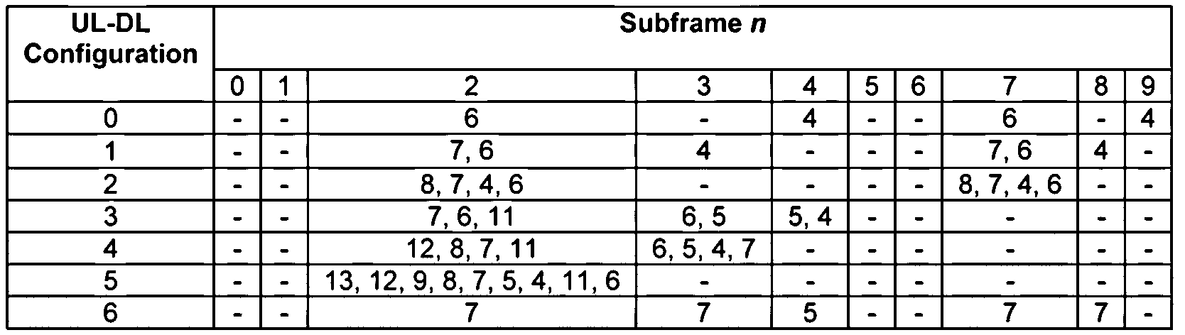
표 2는 각 TDD UL-DL 설정(UL-DL Configuration)의 각 상향링크 서브프레임(Subframe n)에서 몇 서브프레임 이전의 하향링크 서브프레임의 PDSCH HARQ(A/N)가 전송되는지를 나타낸다. 즉, 상향링크 서브프레임 n에서 하향링크 서브프레임 (n-ki)(ki∈K)에서 전송된 PDSCH의 A/N이 전송된다. 예를 들면, TDD UL-DL 설정이 “1”인 경우를 가정한다. 서브프레임 넘버(n)가 2일 때 K={7,6}이고, 이 서브프레임을 통해 서브프레임 넘버가 5 및 6인 하향링크 서브프레임에서 전송된 PDSCH의 A/N이 전송된다. 서브프레임 넘버(n)가 3일 때 K={4}이고, 이 서브프레임을 통해 서브프레임 넘버가 9인 하향링크 서브프레임에서 전송된 PDSCH의 A/N이 전송된다. 서브프레임 넘버(n)가 7일 때 K={7,6}이고, 이 서브프레임을 통해 서브프레임 넘버가 0 및 1인 하향링크 서브프레임에서 전송된 PDSCH의 A/N이 전송된다. 그리고, 서브프레임 넘버(n)가 8일 때 K={4}이고, 이 서브프레임을 통해 서브프레임 넘버가 4인 하향링크 서브프레임에서 전송된 PDSCH의 A/N이 전송된다.
하향링크 서브프레임 (n-ki)(ki∈K)에서 전송된 PDSCH의 A/N에 대하여, PUCCH 자원은 다음의 수학식 1과 같다.
[수학식 1]

수학식 1에서,  는 서브프레임 (n-ki)(ki∈K)에서 전송된 PDSCH의 A/N이 전송되는 PUCCH 자원이다. M은 상향링크 서브프레임(n)에 관련된 하향링크 서브프레임의 개수이고, 0≤i≤M-1이다. c는 {0, 1, 2, 3}에서 선택되고,
  의 식을 만족하며,
  이고,
이고,  는 하향링크 자원 블록(resource block)의 개수,
  는 자원 블록에서 서브캐리어(subcarrier)의 개수(예를 들면, 12)이며,
  는 서브프레임 (n-ki)에서 해당하는 PDCCH의 전송을 위해 사용된 첫 번째 CCE(control channel elements)의 번호이다. SR(Scheduling Request) 전송을 위해 예약된 PUCCH format 1/1a/1b 자원, ARI(Acknowledgement Resource Indication)에 의해 지시된 PUCCH format 1/1a/1b 자원, SPS(Semi-Persistent Scheduling) 전송을 위해 예약된 PUCCH format 1/1a/1b 자원 등을 이용하여 PUCCH format 1/1a/1b이 전송될 수 있고,
  는 SR, ARI, SPS 등의 전송을 위해 예약된 PUCCH 포맷 1/1a/1b 자원을 나타내며 상위계층 시그널링에 의해 설정될 수 있다.
예로써, 시스템 대역폭은 10MHz(50 PRB(Physical Resource Block)),  (SR, ARI, SPS 등이 전송되지 않음)인 경우를 가정한다.
M=1인 경우, c의 값에 따른 PUCCH 자원( )은 다음의 표 3과 같다.
[표 3]

표 3을 참조하면, M=1일 때 i=0이다. nCCE가 0~10일 때 c=0이고  는 0~10이다. nCCE가 11~26일 때 c=1이고
  는 11~26이다. nCCE가 27~43일 때 c=2이고
  는 27~43이다. 그리고, nCCE가 44~60일 때 c=3이고
  는 44~60이다.
M=2인 경우, c의 값에 따른 PUCCH 자원(  )은 다음의 표 4와 같다.
[표 4]

표 4를 참조하면, M=2일 때 i=0,1이다. nCCE가 0~10일 때 c=0이고, i=0인 경우  는 0~10, i=1인 경우
  는 11~21이다. nCCE가 11~26일 때 c=0이고, i=0인 경우
  는 22~37, i=1인 경우
  는 38~53이다. nCCE가 27~43일 때 c=0이고, i=0인 경우
  는 54~70, i=1인 경우
  는 71~87이다. 그리고, nCCE가 44~60일 때 c=0이고, i=0인 경우
  는 88~104, i=1인 경우
  는 105~121이다.
M=3인 경우, c의 값에 따른 PUCCH 자원(  )은 다음의 표 5와 같다.
[표 5]

표 5를 참조하면, M=3일 때 i=0,1,2이다. nCCE가 0~10일 때 c=0이고, i=0인 경우  는 0~10, i=1인 경우
  는 11~21, i=2인 경우
  는 22~32이다. nCCE가 11~26일 때 c=1이고, i=0인 경우
  는 33~48, i=1인 경우
  는 49~64, i=2인 경우
  는 65~80이다. nCCE가 27~43일 때 c=2이고, i=0인 경우
  는 81~97, i=1인 경우
  는 98~114, i=2인 경우
  는 115~131이다. nCCE가 44~60일 때 c=3이고, i=0인 경우
  는 132~148, i=1인 경우
  는 149~165, i=2인 경우
  는 166~182이다.
M=4인 경우, c의 값에 따른 PUCCH 자원(  )은 다음의 표 6과 같다.
[표 6]

표 6을 참조하면, M=3일 때 i=0,1,2,3이다. nCCE가 0~10일 때 c=0이고, i=0인 경우  는 0~10, i=1인 경우
  는 11~21, i=2인 경우
  는 22~32, i=3인 경우
  는 33~43이다. nCCE가 11~26일 때 c=1이고, i=0인 경우
  는 44~59, i=1인 경우
  는 60~75, i=2인 경우
  는 76~91, i=3인 경우
  는 92~107이다. nCCE가 27~43일 때 c=2이고, i=0인 경우
  는 108~124, i=1인 경우
  는 125~141, i=2인 경우
  는 142~158, i=3인 경우
  는 159~175이다. nCCE가 44~60일 때 c=3이고, i=0인 경우
  는 176~192, i=1인 경우
  는 193~209, i=2인 경우
  는 210~226, i=3인 경우
  는 227~243이다.
표 3 내지 6은 M의 값이 1 내지 4인 경우의 예를 나타내지만, M은 최대9(UL-DL 설정이 5에서 서브프레임 2의 경우)의 값을 가질 수 있다. 하지만 UL-DL 설정이 5인 경우에는 오직 A/N bundling mode 만이 PUCCH format 1a/1b를 이용하여 전송이 가능하다.
수학식 1을 이용한 상술한 방법을 이용하여 TDD 시스템에서 하나의 상향링크 서브프레임에서 전송되는 여러 개의 하향링크 서브프레임 내에서 전송되는 PDSCH에 대한 A/N을 충돌 없이 유도할 수 있다. 상술한 방법은 같은 상향링크 서브프레임을 PDSCH A/N 전송을 위해 사용하는 복수의 단말들 사이에서도 사용될 수 있다.
한편, 하나 또는 다수의 요소 반송파(Component Carrier, CC)를 결합하는 다중 반송파 집합화(Carrier Aggregation, CA) 환경에서, 각각의 요소 반송파가 속한 밴드(band)가 상이할 수 있다. 인터 밴드(Inter-Band) 방식으로 반송파 결합이 이루어지는 경우, TDD 설정은 각각의 밴드 별로 상이하게 설정할 수 있다. 그런데, 이러한 상이하게 설정된 밴드들 내에 포함된 반송파들을 하나의 단말이 이용하는 경우가 있다. 이하에서는 이러한 단말을 인터밴드 CA 단말로 부르기로 한다.
도 2는 본 명세서의 일 실시예에 의한 인터밴드간 CA 환경을 보여주는 도면이다.
시스템(210)은 두 요소 반송파가 구성되는 것을 도시하는데, CC1(211)은 고출력(high power)으로 eNB로부터 전송되는 신호의 커버리지를 갖는 반송파이고, CC2(212)는 저출력(low power)으로 eNB로부터 전송되는 신호의 커버리지를 갖는 반송파이다. CC1(211) 및 CC2(212)는 서로 다른 밴드에 포함될 수 있다. CC1(211)의 TDD UL-DL 설정은 상기 표 1에 나타난 1로서 도 2에서 “281”로 도시되고, CC2(212)의 TDD UL-DL 설정은 2로서 도 2에서 “282”로 도시된다. 이때, CC2(212) 커버리지에 있는 단말들을 위해서 CA 구성이 가능하다. 한편, 핫스팟(hot-spot) 영역(215)은 CC1(211) 및 CC2(212)의 CA 환경으로 구성될 수 있다.
CA 환경에서 기지국과 통신을 수행하는 인터밴드 CA 단말은 상이한 TDD 설정을 갖는 CC(예를 들면, CC1(211) 및 CC2(212))를 통해 통신을 수행할 수 있다.
일 예를 들면, 트래픽 적응(traffic adaptation) 목적으로 인터-밴드에서 다른 TDD UL-DL 설정이 이용될 수 있다.
다른 예를 들면, 도 3을 참조하면, 같은 밴드 내에 공존하는 다른 TDD 시스템(예를 들면, TDS-CDMA(310), LTE(320))과의 간섭을 회피하기 위해 TDD 시스템(예를 들면, LTE-A(330, 340))의 TDD 상향링크-하향링크가 설정되고, 따라서 TDD 시스템은 인터-밴드에서 서로 다른 TDD UL-DL 설정이 요구될 수 있다. 즉, 도 3의 예에서, 밴드 A(410)에서 LTE-A(330)는 TDS-CDMA(310)와 간섭을 회피하기 위해 “2”의 TDD UL-DL 설정을 갖고, 밴드 B(420)에서 LTE-A(340)는 LTE(320)와 간섭을 회피하기 위해 “0”의 TDD UL-DL 설정을 가지며, 따라서 서로 다른 밴드에 위치하는 LTE-A(330)와 LTE-A(340)의 TDD UL-DL 설정은 서로 다를 수 있다.
다른 예를 들면, 낮은 주파수 밴드에서는 상향링크 서브프레임이 많은 TDD UL-DL 설정을 따르고, 높은 주파수 밴드에서는 하향링크 서브프레임이 많은 TDD UL-DL 설정을 따르도록 유도할 수 있다. 이는 커버리지 증가에 도움이 될 수 있다.
상술한 예들은, 최대 처리량(peak throughput)에 영향을 줄 수 있다.
이러한 경우, 단말이 인터밴드간에 설정된 서로 다른 TDD 설정으로 인해 발생할 수 있는 충돌 서브프레임 (conflicting subframe)상에서 지원 가능한 전송 모드가 반-이중(Half-Duplex) 모드인지 또는 전-이중(Full-Duplex) 모드인지에 따라, 서브프레임 별로 동작 방식이 상이하게 될 수 있다.
도 4는 도 2의 인터밴드간 CA 환경에서 인터밴드 간에 설정된 서로 다른 TDD 설정으로 인해 발생할 수 있는 충돌 서브프레임 상에서 반-이중 모드인 경우 서브프레임별 동작 방식을 예시하는 도면이다. 도 4의 예에서, PCell(Primary Cell)은 TDD UL-DL 설정 “1”을 따르고 SCell(Secondary Cell)은 TDD UL-DL 설정 “2”를 따른다. 도 4에서, U는 상향링크 전송을 위해 예비된 서브프레임, D는 하향링크 전송을 위해 예비된 서브프레임, S는 하향링크 전송에서 상향링크 전송으로 전환되는 특수(special) 서브프레임이다.
도 4를 참조하면, 서브프레임 넘버 3, 8일 때 PCell은 상향링크로 설정되고 SCell은 하향링크로 설정된다. 이하에서, CC에 따라 상향링크/하향링크가 서로 다른 서브프레임을 충돌 서브프레임(conflicting subframe)으로 부르기로 한다. 단말이 반-이중 모드이기 때문에, PCell의 상향링크 서브프레임 또는 SCell의 하향링크 서브프레임 중 적어도 하나는 뮤트된 서브프레임(muted subframe)으로 동작하게 된다. 도 4의 예에서, 서브프레임 넘버가 3, 8일 때 PCell의 상향링크 서브프레임이 뮤트된 서브프레임이다.
PDSCH에 대한 A/N(PDSCH A/N)을 포함하는 상향링크 제어 채널(PUCCH)는 PCell을 통해서만 전송될 수 있다. 이하에서는 ‘PDSCH A/N’을 ‘PDSCH에 대한 A/N’과 동일한 의미로 사용하기로 한다. 그러나, PCell에서 PDSCH A/N을 전송하는 상향링크 서브프레임이 뮤트된 서브프레임인 경우, 이를 통해서 PDSCH A/N을 전송할 수 없는 경우가 발생할 수 있다.
도 4의 예에서, PCell의 TDD UL-DL 설정이 “1”이므로, 표 2를 참조하면, 서브프레임 넘버 2, 3, 7, 8일 때 PDSCH A/N이 전송될 수 있다. 그러나, 서브프레임 넘버가 3, 8일 때 CC1의 상향링크 서브프레임이 뮤트된 서브프레임인 경우, 서브프레임 넘버 3인 서브프레임을 통해 서브프레임 넘버가 9인 하향링크 서브프레임으로 전송된 PDSCH A/N이 전송될 수 없고, 서브프레임 넘버 8인 서브프레임을 통해 서브프레임 넘버가 4인 하향링크 서브프레임으로 전송된 PDSCH A/N이 전송될 수 없다.
도 5는 도 2의 인터밴드간 CA 환경에서 단말이 전-이중 모드인 경우 서브프레임별 동작 방식을 도시하는 도면이다. 도 5에서, PCell은 TDD UL-DL 설정 “1”을 따르고 SCell은 TDD UL-DL 설정 “2”를 따른다. 도 5에서, U는 상향링크 전송을 위해 예비된 서브프레임, D는 하향링크 전송을 위해 예비된 서브프레임, S는 하향링크 전송에서 상향링크 전송으로 전환되는 특수 서브프레임이다.
도 5를 참조하면, 서브프레임 넘버 3, 8일 때 PCell은 상향링크로 설정되고 SCell은 하향링크로 설정된다. 단말이 인터밴드간에 설정된 서로 다른 TDD 설정으로 인해 발생할 수 있는 충돌 서브프레임상에서 전-이중 모드이기 때문에, 단말은 심지어 충돌 서브프레임 상에서도 동시에 PCell을 통해 상향링크 신호를 전송할 수 있고 SCell을 통해 하향링크 신호를 수신할 수 있다.
PDSCH A/N을 포함하는 PUCCH는 PCell을 통해서만 전송될 수 있다. 그러나, 특정 하향링크 서브프레임을 통해 전송된 PDSCH A/N이 전송될 수 없는 경우가 발생할 수 있다.
도 5의 예에서, PCell의 TDD UL-DL 설정이 “1”이므로, 표 2를 참조하면, 서브프레임 넘버 2, 3, 7, 8일 때 PDSCH A/N이 전송될 수 있다. 보다 상세하게는, 표 2에서 상향링크 서브프레임 넘버가 2일 때 K={7,6}이므로 서브프레임 넘버가 5, 6인 하향링크 서브프레임을 통해 전송된 PDSCH A/N이 전송되고, 상향링크 서브프레임 넘버가 3일 때 K={4}이므로 서브프레임 넘버가 9인 하향링크 서브프레임을 통해 전송된 PDSCH A/N이 전송되며, 상향링크 서브프레임 넘버가 7일 때 K={7,6}이므로 서브프레임 넘버가 0, 1인 하향링크 서브프레임을 통해 전송된 PDSCH A/N이 전송되고, 서브프레임 넘버가 8일 때 K={4}이므로 서브프레임 넘버가 4인 하향링크 서브프레임을 통해 전송된 PDSCH A/N이 전송될 수 있다. 정리하면, 서브프레임 넘버가 2, 3, 7, 8일 때 서브프레임 넘버가 0, 1, 4, 5, 6, 9인 하향링크 서브프레임을 통해 전송된 PDSCH A/N이 전송된다.
한편, SCell의 TDD UL-DL 설정이 “2”이므로, 표 2를 참조하면, 서브프레임 넘버가 0, 1, 3, 4, 5, 6, 8, 9인 경우에 하향링크로 PDSCH가 전송될 수 있다. SCell을 통해 전송된 PDSCH의 A/N이 PCell을 통해 전송될 때, 이 중 서브프레임 넘버가 0, 1, 4, 5, 6, 9인 경우에 대하여는 PDSCH A/N을 전송하는 타이밍이 PCell의 UL-DL 설정에 의해 결정될 수 있지만, 서브프레임 넘버가 3, 8인 경우에 대하여는 PDSCH A/N을 전송하는 타이밍은 설정되어 있지 않다.
상술한 바와 같이, 복수의 CC에서 서로 다른 TDD UL-DL 설정을 이용하는 경우, 표 2에 따른 PDSCH A/N 전송 타이밍을 사용할 수 없는 문제가 발생할 수 있다.
이러한 문제를 극복하기 위해 PDSCH A/N 전송 타이밍을 위한 기준 TDD 설정을 이용할 수 있다.
본 명세서에서, 기준 TDD 설정은, (1) PCell과 SCell에서 설정된 2개의 다른 TDD UL-DL 설정을 비교하는 단계, (2) 2개의 TDD UL-DL 설정에서 공통의 상향링크 서브프레임을 검색하는 단계, (3) PDSCH A/N을 전송하는 상향링크 서브프레임이 상기 공통의 상향링크 서브프레임에 속하는 하나 이상의 기준 TDD 설정을 검색하는 단계, 및 (4) 하나 이상의 기준 TDD 설정으로부터 단말에 특정된 기준 TDD 설정을 선택하는 단계를 통해 기지국(및/또는 단말)에 의해 구해질 수 있다. 구해진 단말에 특정된 기준 TDD 설정은 RRC(Radio Resource Control) 또는 PDSCH와 같은 하향링크 신호를 통해 기지국으로부터 단말로 전달될 수 있다. 또는 사전에 미리 정해진 규칙에 의해서 동작할 수 있다.
또는, 기준 TDD 설정은, (1’) PCell의 TDD UL-DL 설정과 SCell의 TDD UL-DL 설정이 다른 모든 경우에 대하여 상술한 (1) 내지 (3)의 단계를 실행하여 만들어진 다음의 표 7을 구비하는 단계, (2’) PCell의 TDD UL-DL 설정과 SCell의 TDD UL-DL 설정을 표 7에 적용하여 하나 이상의 기준 TDD 설정을 검색하는 단계, 및 (3’) 하나 이상의 기준 TDD 설정으로부터 단말에 특정된 기준 TDD 설정을 선택하는 단계를 통해 기지국(및/또는 단말)에 의해 구해질 수 있다. 구해진 단말에 특정된 기준 TDD 설정은 RRC 또는 PDSCH와 같은 하향링크 신호를 통해 기지국으로부터 단말로 전달될 수 있다. 또는 사전에 미리 정해진 규칙에 의해서 동작할 수 있다.
[표 7]

예를 들면, PCell(CC0)의 TDD UL-DL 설정이 0이고 SCell(CC1)의 TDD UL-DL 설정이 1인 때, 상술한 (1) 내지 (3)의 단계를 이용하거나 또는 표 7을 이용하면 하나 이상의 기준 TDD 설정은 1, 2, 4, 5이고, 기지국은 이들 중 하나의 값(예를 들면, 1)을 단말에 특정된 기준 TDD 설정으로 선택한다. 그리고, 기지국은 단말로 선택된 기준 TDD 설정 정보를 전송한다. 또는 사전에 특정한 기준으로 특정한 값으로 정해진다.
기준 TDD 설정 정보를 수신한 단말은, PCell(CC0)에서 상향링크-하향링크 통신 타이밍은 표 1에서 TDD UL-DL 설정 0의 경우를 따르고, SCell(CC1)에서 상향링크-하향링크 통신 타이밍은 표 1에서 TDD UL-DL 설정 1의 경우를 따르며, PCell(CC0)에서 PDSCH A/N 전송의 타이밍은 표 2에서 기준 TDD 설정 1을 따를 수 있다.
도 6은 기준 TDD 설정에 따른 PDSCH A/N 전송을 예시하는 도면으로서, 제 1 단말의 PCell(CC0)의 TDD UL-DL 설정이 0, SCell(CC1)의 TDD UL-DL 설정이 1, 기준 TDD 설정이 1인 경우를 도시한다. 기준 TDD 설정이 1인 경우, 표 2를 참조하면, n=2일 때 K={7,6}으로 M=2이고, n=3일 때 K={4}로 M=1이며, n=7일 때 K={7,6}으로 M=2이고, n=8일 때 K={4}로 M=1이다.
PCell(CC0)의 서브프레임 2에서는 PCell(CC0) 및 SCell(CC1)의 서브프레임 5, 6의 PDSCH A/N이 전송될 수 있다.
PCell(CC0)의 서브프레임 3에서는 SCell(CC1)의 서브프레임 9의 PDSCH A/N이 전송될 수 있다. PCell(CC0)의 서브프레임 9는 상향링크 서브프레임이므로 PCell의 서브프레임 9의 PDSCH A/N은 전송되지 않는다. 단말이 반-이중 모드이고 SCell의 서브프레임 9가 뮤팅되는 경우, SCell의 서브프레임 9의 PDSCH A/N은 전송되지 않을 수 있다.
PCell(CC0)의 서브프레임 7에서는 PCell(CC0) 및 SCell(CC1)의 서브프레임 0, 1의 PDSCH A/N이 전송될 수 있다.
PCell(CC0)의 서브프레임 8에서는 SCell(CC1)의 서브프레임 4에서 전송된 PDSCH에 대한 A/N이 전송될 수 있다. PCell(CC0)의 서브프레임 4는 상향링크 서브프레임이므로 PCell의 서브프레임 4의 PDSCH A/N은 전송되지 않는다. 단말이 반-이중 모드이고 SCell의 서브프레임 4가 뮤팅되는 경우, SCell의 서브프레임 4의 PDSCH A/N은 전송되지 않을 수 있다.
한편, 무선 통신 시스템 내에는 하나의 CC만을 이용하고 CA 기술을 이용하지 않는 단말이 동시에 존재할 수 있다. CA 기술을 이용하지 않는 단말은 CA 기술을 이용할 수 없는 레거시(legacy) 단말 또는 CA 기술을 이용할 수 있지만 설정에 의해 CA 기술을 이용하지 않는 단말일 수 있다. 이하에서는 설명의 편의를 위해 레거시 단말로 부르기로 한다. 도 6에서, 제 2 단말은 CC0을 이용하여 기지국과 통신하고 CC1은 이용하지 않는다.
제 2 단말은 TDD UL-DL 설정 0을 따라 기지국과 통신을 한다. 즉, 상향링크-하향링크 통신 타이밍은 표 1에서 TDD UL-DL 설정 0을 따르고, PDSCH A/N 전송은 표 2에서 TDD UL-DL 설정 0을 따른다.
TDD UL-DL 설정 0인 경우, 표 2를 참조하면, n=2일 때 K={6}으로 M=1이고, n=4일 때 K={4}로 M=1이며, n=7일 때 K={6}으로 M=1이고, n=9일 때 K={4}로 M=1이다.
서브프레임 2에서는 서브프레임 6의 PDSCH A/N이 전송될 수 있다. 서브프레임 4에서는 서브프레임 0의 PDSCH A/N이 전송될 수 있다. 서브프레임 7에서는 서브프레임 1의 PDSCH A/N이 전송될 수 있다. 그리고, 서브프레임 9에서는 서브프레임 5의 PDSCH A/N이 전송될 수 있다.
상술한 바와 같이, CA 기술을 이용하는 제 1 단말과 CA 기술을 이용하지 않는 제 2 단말이 동일한 요소 반송파(CC0)에서 PDSCH A/N을 전송하는 경우, PDSCH A/N 정보가 전송되는 PUCCH 자원이 충돌할 수 있다.
예를 들면, 제 1 단말의 서브프레임 2 및 7에서 M=2이고, 따라서 수학식 1에 M=2를 대입하여 제 1 단말의 PUCCH 자원이 할당될 수 있다. 이에 비하여, 제 2 단말의 서브프레임 2 및 7에서 M=1이고, 따라서 수학식 1에 M=1을 대입하여 제 2 단말의 PUCCH 자원이 할당될 수 있다. 이러한 경우, 제 1 단말과 제 2 단말은 서로 다른 M의 값을 이용하여 PUCCH 자원을 할당하기 때문에 이들의 PUCCH 자원이 충돌할 수 있다.
일 예로, 시스템 대역폭이 10MHz,  인 경우, 제 1 단말의 서브프레임 2 및 7의 PUCCH 자원은 표 4와 같이 할당되고, 제 2 단말의 서브프레임 2 및 7의 PUCCH 자원은 표 3과 같이 할당된다.
제 1 단말에 대해 서브프레임 5에서 PDSCH가 전송되고 PDSCH에 해당하는 PDCCH의 전송에 사용된 첫 번째 CCE가 11인 때, 표 4를 참조하면, c는 1, i는 0, PDSCH A/N이 할당되는 PUCCH 자원(  )은 22일 수 있다. 한편, 제 2 단말에 대해 서브프레임 6에서 PDSCH가 전송되고 PDSCH에 해당하는 PDCCH의 전송에 사용된 첫 번째 CCE가 22인 때, 표 3을 참조하면, c는 1, i는 0, PDSCH A/N이 할당되는 PUCCH 자원(
  )은 22일 수 있다. 이러한 경우, 두 개의 PDSCH A/N이 동일한 PUCCH 자원을 통해 전송되어 충돌하게 된다.
이러한 PUCCH 충돌은 CA 기술을 이용하는 단말의 기준 TDD 설정이 PCell의 TDD UL-DL 설정과 다른 경우 발생할 수 있다. 다음의 표 8에서 강조된 부분은 PUCCH 충돌이 발생할 수 있는 경우를 나타낸다.
[표 8]

또한, PUCCH 충돌은 CA 기술을 이용하는 복수의 단말의 기준 TDD 설정이 서로 다른 경우에도 발생할 수 있다. 예를 들면, 복수의 단말에서 PCell은 같게 설정되고 SCell은 다르게 설정될 수 있고, 이러한 경우 기준 TDD 설정이 서로 다를 수 있다. 또는, 복수의 단말에서 PCell 및 SCell이 같게 설정되지만, 단말의 환경에 따라 선택된 기준 TDD 설정은 서로 다를 수 있다. 이러한 경우에, 복수의 단말 사이에서 PUCCH 충돌이 발생할 가능성이 있다.
도 7은 일 실시예에 따른 인터밴드 CA 단말의 PDSCH A/N 전송 방법을 도시한다.
도 7을 참조하면, PDSCH A/N 전송 방법은, 인터밴드 CA 단말에 설정된 TDD 설정 정보를 확인하는 단계(S710), 레거시 단말과 인터밴드 CA 단말에 설정된 PDSCH A/N 타이밍을 비교하는 단계(S720), 레거시 단말과 인터밴드 CA 단말에 대하여 특정한 동일 상향링크 서브프레임에 연관된 동일한 하향링크 서브프레임을 탐색하는 단계(S730), 상기 동일한 하향링크 서브프레임의 경우 수학식 1을 이용하여 PDSCH A/N 자원을 할당하는 단계(S740), 상기 동일한 하향링크 서브프레임이 아닌 서브프레임의 경우 인터밴드 CA 단말에게만 적용되는 규칙(후술될 수학식 2)을 이용하여 PDSCH A/N 자원을 할당하는 단계(S750), 및 할당된 자원으로 PDSCH A/N을 전송하는 단계(S760)를 포함한다.
인터밴드 CA 단말은 설정된 TDD 설정 정보를 확인한다(S710). TDD 설정 정보는 전-이중 모드 또는 반-이중 모드 설정 정보, PCell 및 SCell에서 TDD UL-DL 설정 정보, PDSCH A/N 전송 타이밍 정보를 나타내는 기준 TDD 설정 정보 등을 포함할 수 있다. 기준 TDD 설정 정보는 기지국으로부터 RRC(Radio Resource Control) 또는 PDCCH를 통해 전달될 수 있고, 인터밴드 CA 단말은 기준 TDD 설정 정보를 수신하여 기준 TDD 설정을 확인할 수 있다. 또는, 기준 TDD 설정을 선택하는 규칙이 기지국과 인터밴드 CA 단말 사이에서 사전에 설정되어 공유될 수 있고, 인터밴드 CA 단말이 사전에 설정된 규칙을 이용하여 기준 TDD 설정을 확인할 수 있다.
인터밴드 CA 단말은 레거시 단말과 인터밴드 CA 단말에 설정된 PDSCH A/N 타이밍을 비교한다(S720). 레거시 단말에 설정된 PDSCH A/N 타이밍은 PCell에 설정된 TDD UL-DL 설정 및 표 2를 이용하여 결정할 수 있다. 인터밴드 CA 단말에 설정된 PDSCH A/N 타이밍은 확인한 기준 TDD 설정 및 표 2를 이용하여 결정할 수 있다.
예를 들면, PCell의 TDD UL-DL 설정이 0, SCell의 TDD UL-DL 설정이 1, 그리고 기준 TDD 설정이 1인 경우를 가정한다. PCell을 이용하는 레거시 단말에 대해서는 TDD UL-DL 설정이 0이고, 표 2를 참조하면, 서브프레임 2에서 K={6}(M은 1), 서브프레임 4에서 K={4}(M은 1), 서브프레임 7에서 K={6}(M은 1), 그리고 서브프레임 9에서 K={4}(M=1)이다. 인터밴드 CA 단말에 대해서는 기준 TDD 설정이 1이고, 표 2를 참조하면, 서브프레임 2에서 K={7, 6}(M은 2), 서브프레임 3에서 K={4}(M은 1), 서브프레임 7에서 K={7, 6}(M은 2), 그리고 서브프레임 8에서 K=4(M은 1)이다.
서브프레임 3 및 8에서 인터밴드 CA 단말은 PDSCH A/N을 전송하지만 레거시 단말은 PDSCH A/N을 전송하지 않으므로, 서브프레임 3 및 8에서는 PUCCH 자원이 충돌하지 않는다. 따라서, 서브프레임 3 및 8에서는 전술한 수학식 1을 이용하여 PUCCH 자원을 할당할 수 있다.
서브프레임 2 및 7에서 레거시 단말의 M 값은 1이고 인터밴드 CA 단말의 M 값은 2이므로, 서브프레임 2 및 7에서는 PUCCH 자원이 충돌할 가능성이 있다.
다음으로, 인터밴드 CA 단말은 레거시 단말과 인터밴드 CA 단말에 대하여 특정한 동일 상향링크 서브프레임에 연관된 동일한 하향링크 서브프레임을 탐색한다(S730). 인터밴드 CA 단말이 상술한 기준 TDD 설정을 이용할 경우, 상기 동일한 하향링크 서브프레임은 레거시 단말에 설정된 하향링크 서브프레임과 같다. 하향링크에서 상향링크로 전환되는 특수 서브프레임(S)의 일부 자원에서 하향링크 통신이 수행될 수 있고, 본 명세서에서 하향링크 서브프레임은 하향링크 서브프레임(D) 외에 특수 서브프레임(S)을 포함한다.
상술한 PCell의 TDD UL-DL 설정이 0, SCell의 TDD UL-DL 설정이 1, 그리고 기준 TDD 설정이 1인 예에서, 서브프레임 2에서 레거시 단말은 서브프레임 6에서 전송된 PDSCH의 A/N을 전송하고 인터밴드 CA 단말은 서브프레임 5 및 6에서 전송된 PDSCH의 A/N을 전송하므로, 서브프레임 2에 연관된 동일한 하향링크 서브프레임은 서브프레임 6(또는, n-6)이고, 동일하지 않은 하향링크 서브프레임은 5(또는 n-7)이다. 서브프레임 7에서 레거시 단말은 서브프레임 1에서 전송된 PDSCH의 A/N을 전송하고 인터밴드 CA 단말은 서브프레임 0 및 1에서 전송된 PDSCH의 A/N을 전송하므로, 서브프레임 6에 연관된 동일한 하향링크 서브프레임은 서브프레임 1(또는, n-6)이고, 동일하지 않은 하향링크 서브프레임은 0(또는 n-7)이다.
인터밴드 CA 단말은 상기 동일한 하향링크 서브프레임의 경우 수학식 1을 이용하여 PDSCH A/N 자원을 할당한다(S740). 이때, 수학식 1에 사용되는 M의 값은 PCell의 TDD UL-DL 설정(즉, 레거시 단말의 TDD UL-DL 설정)에 의해 결정된다.
상술한 PCell의 TDD UL-DL 설정이 0, SCell의 TDD UL-DL 설정이 1, 그리고 기준 TDD 설정이 1인 예에서, 서브프레임 2의 경우, 동일한 하향링크 서브프레임인 서브프레임 6을 통해 전송된 PDSCH의 A/N은 수학식 1에 M=1을 대입하여 결정된다. 이러한 경우, 서브프레임 2에서 전송되는 인터밴드 CA 단말의 하향링크 서브프레임 6의 PDSCH A/N을 위한 PUCCH 자원은 레거시 단말의 하향링크 서브프레임 6의 PDSCH A/N을 위한 PUCCH 자원과 충돌하지 않는다.
그리고, 서브프레임 7의 경우, 동일한 하향링크 서브프레임인 서브프레임 1을 통해 전송된 PDSCH의 A/N은 수학식 1에 M=1을 대입하여 결정된다. 이러한 경우, 서브프레임 7에서 전송되는 인터밴드 CA 단말의 하향링크 서브프레임 1의 PDSCH A/N을 위한 PUCCH 자원은 레거시 단말의 하향링크 서브프레임 1의 PDSCH A/N을 위한 PUCCH 자원과 충돌하지 않는다.
인터밴드 CA 단말은 상기 동일한 하향링크 서브프레임이 아닌 서브프레임의 경우 인터밴드 CA 단말에게만 적용되는 규칙을 이용하여 PDSCH A/N 자원을 할당한다(S750). 인터밴드 CA 단말에게만 적용되는 규칙은 다음의 수학식 2와 같을 수 있다.
[수학식 2]

수학식 2에서, P는 상향링크 서브프레임에 연관된 하향링크 서브프레임 중 상기 동일한 하향링크 서브프레임이 아닌 나머지 서브프레임의 개수이다. 상향링크 서브프레임에 연관된 하향링크 서브프레임의 개수가 M’이고 동일한 하향링크 서브프레임의 개수(또는 레거시 단말의 경우 하향링크 서브프레임의 개수)가 M인 때, P=M’-M이다. 상술한 예에서, 서브프레임 2 및 7에 연관된 하향링크 서브프레임의 개수(M’)는 2이고 동일한 하향링크 서브프레임의 개수는 1이므로, P=1이다.


상술한 PCell의 TDD UL-DL 설정이 0, SCell의 TDD UL-DL 설정이 1, 그리고 기준 TDD 설정이 1인 예에서, M’=2이고 M=1이므로 P=1이다. 시스템 대역폭이 10MHz,  인 경우 N
c=
4의 값은 61이다(표 3 참조).
인 경우 N
c=
4의 값은 61이다(표 3 참조).
이때, S740 단계에서 구한 PDSCH A/N을 위한 PUCCH 자원 및 S750 단계에서 구한 PDSCH A/N을 위한 PUCCH 자원은 각각 다음의 표 9 및 표 10으로 정리될 수 있다. 표 9는 전술한 표 3과 같다.
[표 9]

[표 10]

표 9 내지 10을 참조하면, 서브프레임 2에서 전송되는 인터밴드 CA 단말의 서브프레임 6의 PDSCH A/N은 PUCCH 자원 0 내지 60에 할당되고 서브프레임 5의 PDSCH A/N은 PUCCH 자원 61 내지 121에 할당된다. 그리고, 서브프레임 7에서 전송되는 인터밴드 CA 단말의 서브프레임 1의 PDSCH A/N은 PUCCH 자원 0 내지 60에 할당되고 서브프레임 0의 PDSCH A/N은 PUCCH 자원 61 내지 121에 할당된다.
한편, 서브프레임 2에서 전송되는 레거시 단말의 서브프레임 6의 PDSCH A/N은 PUCCH 자원 0 내지 60에 할당되고, 이는 인터밴드 CA 단말의 PUCCH 자원과 충돌하지 않게 된다. 그리고, 서브프레임 7에서 전송되는 레거시 단말의 서브프레임 1의 PDSCH A/N은 PUCCH 자원 0 내지 60에 할당되고, 이는 인터밴드 CA 단말의 PUCCH 자원과 충돌하지 않게 된다.
그리고, 인터밴드 CA 단말은 S740 및 S750 단계에서 구해진 자원에 PDSCH A/N을 할당하여 PUCCH를 전송한다(S760).
상술한 실시예에서 S750 단계, S760 단계의 순서로 설명되었지만 이는 설명의 편의를 위한 것이고, S760 단계, S750 단계의 순서로 실행되거나, S750 단계 및 S760 단계가 동시에 실행될 수도 있다.
도 8은 일 실시예에 따른 기지국의 PDSCH A/N 수신 방법을 도시한다.
도 8을 참조하면, 기지국의 PDSCH A/N 수신 방법은, 단말이 전송한 PUCCH를 수신하는 단계(S810), PUCCH를 수신한 상향링크 서브프레임에 관련된 하향링크 서브프레임 중 레거시 단말과 인터밴드 CA 단말 사이에 동일한 하향링크 서브프레임(즉, 레거시 단말에 설정된 하향링크 서브프레임)의 PDSCH A/N이 할당된 영역으로부터 레거시 단말이 전송한 PDSCH A/N 및 인터밴드 CA 단말이 전송한 PDSCH A/N을 추출하는 단계(S820), 및 PUCCH를 수신한 상향링크 서브프레임에 관련된 하향링크 서브프레임 중 레거시 단말과 인터밴드 CA 단말 사이에 동일하지 않은 하향링크 서브프레임(즉, 레거시 단말에 설정되지 않은 하향링크 서브프레임 또는 인터밴드 CA 단말에 추가로 설정된 하향링크 서브프레임)의 PDSCH A/N이 할당된 영역으로부터 인터밴드 CA 단말이 전송한 PDSCH A/N을 추출하는 단계(S830)를 포함한다.
기지국은 특정 상향링크 서브프레임을 통해 PUCCH를 수신한다(S810).
다음으로, 기지국은 특정 상향링크 서브프레임에 관련된 하향링크 서브프레임 중 레거시 단말과 인터밴드 CA 단말 사이에 동일한 하향링크 서브프레임의 PDSCH A/N이 할당된 영역으로부터 레거시 단말 및 인터밴드 CA 단말이 전송한 PDSCH A/N을 추출한다(S820). 인터밴드 CA 단말이 상술한 기준 TDD 설정을 이용하는 경우, 상기 동일한 하향링크 서브프레임은 레거시 단말에 설정된 하향링크 서브프레임과 같다.
이때, 각 PUCCH 자원에 어떠한 PDSCH A/N이 할당되었는지는 수학식 1을 이용하여 알 수 있다. 수학식 1을 참조하면, 동일한 하향링크 서브프레임의 PDSCH A/N이 묵시적인 방법으로(즉, PDSCH 전송을 지시하는 PDCCH가 전송되는 가장 작은 CCE인덱스로부터 PUCCH 자원을 유도하는 방법) 할당된 자원 영역은  내지
내지  이고, 이 범위 내에서 레거시 단말 및 인터밴드 CA 단말이 전송한 PDSCH A/N을 추출할 수 있다. 이 영역에서 인터밴드 CA 단말이 전송한 PDSCH A/N은 상기 동일한 하향링크 서브프레임을 통해 인터밴드 CA 단말이 수신한 PDSCH에 대한 A/N이다.
그리고, 기지국은 특정 상향링크 서브프레임에 관련된 하향링크 서브프레임 중 레거시 단말과 인터밴드 CA 단말 사이에 동일하지 않은 하향링크 서브프레임의 PDSCH A/N이 할당된 영역으로부터 인터밴드 CA 단말이 전송한 PDSCH A/N을 추출한다(S830). 인터밴드 CA 단말이 상술한 기준 TDD 설정을 이용하는 경우, 상기 동일하지 않은 하향링크 서브프레임은 레거시 단말에 설정되지 않은 하향링크 서브프레임 또는 인터밴드 CA 단말에 추가로 설정된 하향링크 서브프레임이다.
이때, 각 PUCCH 자원에 어떠한 PDSCH A/N이 할당되었는지는 수학식 2를 이용하여 알 수 있다. 수학식 2를 참조하면, 동일하지 않은 하향링크 서브프레임의 PDSCH A/N이 할당된 자원 영역은  이상이고, 이 범위 내에서 인터밴드 CA 단말이 전송한 PDSCH A/N을 추출할 수 있다. 이 영역에서 인터밴드 CA 단말이 전송한 PDSCH A/N은 상기 동일하지 않은 하향링크 서브프레임을 통해 인터밴드 CA 단말이 수신한 PDSCH에 대한 A/N이다.
상술한 실시예에서 S820 단계, S830 단계의 순서로 설명되었지만 이는 설명의 편의를 위한 것이고, S830 단계, S820 단계의 순서로 실행되거나, S820 단계 및 S830 단계가 동시에 실행될 수도 있다.
도 9는 일 실시예에 따른 단말의 구성을 도시하는 블록도이다.
도 9를 참조하면, 단말(900)은 수신부(910), 송신부(920) 및 제어부(930)를 포함한다. 도 9에 도시된 단말(900)은 인터밴드 CA 단말이다.
수신부(910)는 설정된 하향링크 서브프레임에서 PDSCH 및 PDCCH를 수신한다. 하향링크 서브프레임은 TDD UL-DL 설정 및 표 1에 기초하여 결정될 수 있다.
제어부(930)는 도 7의 S710 내지 S750 단계를 실행하여 PDSCH A/N을 위한 PUCCH 자원을 할당한다. 즉, 제어부(930)는 기준 TDD 설정을 확인하고, PCell에서 TDD UL-DL 설정에 따른 PDSCH A/N 전송 상향링크 서브프레임과 기준 TDD 설정에 따른 PDSCH A/N 전송 상향링크 서브프레임을 확인하며, PDSCH A/N을 전송하는 특정 상향링크 서브프레임에 관련된 하향링크 서브프레임 중 레거시 단말과 인터밴드 CA 단말 사이에서 동일한 하향링크 서브프레임을 찾고, 동일한 하향링크 서브프레임에 대하여는 수학식 1을 이용하여 PDSCH A/N을 위한 자원을 설정하고, 동일하지 않은 하향링크 서브프레임에 대하여는 수학식 2를 이용하여 PDSCH A/N을 위한 자원을 설정한다.
송신부(920)는 기준 TDD 설정에 의해 정해진 상향링크 서브프레임에서 제어부(930)가 수학식 1 및 2를 이용하여 설정한 자원에 PDSCH A/N을 매핑하여 전송한다.
도 10은 일 실시예에 따른 기지국의 구성을 도시하는 블록도이다.
도 10을 참조하면, 기지국(1000)은 송신부(1010), 수신부(1020) 및 제어부(1030)를 포함한다.
송신부(1010)는 설정된 하향링크 서브프레임에서 PDSCH 및 PDCCH를 전송한다. 하향링크 서브프레임은 TDD UL-DL 설정 및 표 1에 기초하여 결정될 수 있다.
수신부(1020)는 설정된 상향링크 서브프레임에서 PUCCH를 통해 PDSCH A/N을 수신한다. 레거시 단말로부터 전송된 PDSCH A/N의 타이밍은 TDD UL-DL 설정 및 표 2에 기초하여 결정될 수 있고, 인터밴드 CA 단말로부터 전송된 PDSCH A/N의 타이밍은 기준 TDD 설정 및 표 2에 기초하여 결정될 수 있다.
제어부(1030)는 레거시 단말과 인터밴드 CA 단말 사이에 동일한 하향링크 서브프레임의 PDSCH A/N이 할당된 영역으로부터 수학식 1을 이용하여 레거시 단말 및 인터밴드 CA 단말이 전송한 PDSCH A/N을 추출하고, 레거시 단말과 인터밴드 CA 단말 사이에 동일하지 않은 하향링크 서브프레임의 PDSCH A/N이 할당된 영역으로부터 수학식 2를 이용하여 인터밴드 CA 단말이 전송한 PDSCH A/N을 추출한다. 그리하여, 기지국(1000)은 단말의 PDSCH 수신 여부를 확인할 수 있다.
상술한 실시예는 PDSCH A/N을 전송하는 PUCCH 포맷 1/1a/1b의 경우에 적용될 수 있다. 한편, PUCCH 포맷 3의 경우, km∈K 내에서 오직 DAI(Downlink Assignment Index)가 1인 상황에서는, PUCCH 포맷 3의 자원이 사용되지 않고 PUCCH 포맷 1a/1b 전송이 이용될 수 있다. 이러한 경우, 상술한 바와 같은 PCell 상의 레거시 단말과 인터밴드 CA 단말 사이의 PUCCH 자원 충돌 문제가 발생할 수 있다. 즉, 레거시 단말의 DAI=1을 가지는 관련 하향링크 서브프레임(M=1)에 대한 PUCCH 자원과 인터밴드 CA 단말의 PUCCH 자원이 서로 충돌할 수 있다. 이러한 경우에도 상술한 실시예가 적용될 수 있다.
이상의 설명은 본 발명의 기술 사상을 예시적으로 설명한 것에 불과한 것으로서, 본 발명이 속하는 기술 분야에서 통상의 지식을 가진 자라면 본 발명의 본질적인 특성에서 벗어나지 않는 범위에서 다양한 수정 및 변형이 가능할 것이다. 따라서, 본 발명에 개시된 실시 예들은 본 발명의 기술 사상을 한정하기 위한 것이 아니라 설명하기 위한 것이고, 이러한 실시 예에 의하여 본 발명의 기술 사상의 범위가 한정되는 것은 아니다. 본 발명의 보호 범위는 아래의 청구범위에 의하여 해석되어야 하며, 그와 동등한 범위 내에 있는 모든 기술 사상은 본 발명의 권리범위에 포함되는 것으로 해석되어야 할 것이다.
CROSS-REFERENCE TO RELATED APPLICATION
본 특허출원은 2011년 12월 23일 한국에 출원한 특허출원번호 제 10-2011-0141630 호에 대해 미국 특허법 119(a)조 (35 U.S.C § 119(a))에 따라 우선권을 주장하며, 그 모든 내용은 참고문헌으로 본 특허출원에 병합된다. 아울러, 본 특허출원은 미국 이외에 국가에 대해서도 위와 동일한 이유로 우선권을 주장하면 그 모든 내용은 참고문헌으로 본 특허출원에 병합된다.
Claims (10)
- 특정 상향링크 서브프레임에 대해 프라이머리 셀(Primary Cell)에 설정된 TDD(Time Division Duplex) 설정에 기초하여 결정된 적어도 하나의 제 1 연관 하향링크 서브프레임과, 상기 특정 상향링크 서브프레임에 대해 프라이머리 셀과 세컨더리 셀(Secondary Cell)의 TDD 설정에 기초하여 선택된 기준 TDD 설정에 기초하여 결정된 적어도 하나의 제 2 연관 하향링크 서브프레임을 결정하고, 상기 제 1 연관 하향링크 서브프레임과 제 2 연관 하향링크 서브프레임을 비교하여 동일한 하향링크 서브프레임인 적어도 하나의 제 1 하향링크 서브프레임을 검색하는 단계;상기 특정 상향링크 서브프레임에서 상기 제 1 하향링크 서브프레임에서 수신된 PDSCH(Physical Downlink Shared Channel)의 A/N(Ack/Nack)이 할당되는 자원을 상기 프라이머리 셀에 설정된 TDD 설정에 기초하여 결정하는 단계;상기 특정 상향링크 서브프레임에서 상기 제 2 연관 하향링크 서브프레임 중 상기 제 1 하향링크 서브프레임이 아닌 제 2 하향링크 서브프레임에서 수신된 PDSCH의 A/N이 할당되는 자원을 상기 제 1 하향링크 서브프레임에서 수신된 PDSCH A/N이 할당된 자원 외에서 결정하는 단계; 및상기 제 1 하향링크 서브프레임에서 수신된 PDSCH A/N이 할당되는 자원 및 상기 제 2 하향링크 서브프레임에 수신된 PDSCH A/N이 할당되는 자원에 PDSCH A/N을 매핑하여 전송하는 단계를 포함하는 것을 특징으로 하는 단말의 PDSCH A/N 전송 방법.
- 제 1 항에 있어서,상기 제 1 하향링크 서브프레임에서 수신된 PDSCH의 A/N이 할당된 자원()은 다음의 식 1에 의해 결정되고, [식 1]

 상기 제 2 하향링크 서브프레임에서 수신된 PDSCH의 A/N이 할당된 자원()은 다음의 식 2에 의해 결정되는 것을 특징으로 하는 단말의 PDSCH A/N 전송 방법.
 [식 2]
[식 2] 상기 식 1 및 2에서, M은 상기 제 1 하향링크 서브프레임의 개수, i는 각 제 1 하향링크 서브프레임의 인덱스(0≤i≤M-1),이고
 의 식을 만족하며,
 는 하향링크 자원 블록의 개수,
 는 자원 블록에서 서브캐리어의 개수,
 는 각 제 1 하향링크 서브프레임에서 PDSCH에 해당하는 제어 정보를 전송하는 PDCCH(Physical Downlink Control Channel)의 전송을 위해 사용된 첫 번째 CCE(control channel elements)의 번호,
 는 PDSCH A/N이 아닌 제어 정보를 위해 할당되는 자원의 개수, P는 상기 제 2 하향링크 서브프레임의 개수, i는 각 제 2 하향링크 서브프레임의 인덱스(0≤i≤P-1),
 는 상기 제 1 하향링크 서브프레임에서 수신된 PDSCH의 A/N이 할당될 수 있는 자원의 개수이다.
- 제 1 항에 있어서,상기 프라이머리 셀에 설정된 TDD 설정과 상기 기준 TDD 설정이 다른 경우, 상기 제 1 하향링크 서브프레임에서 수신된 PDSCH의 A/N이 할당되는 자원을 결정하는 단계 및 상기 제 2 하향링크 서브프레임에서 수신된 PDSCH의 A/N이 할당되는 자원을 결정하는 단계가 실행되는 것을 특징으로 하는 단말의 PDSCH A/N 전송 방법.
- PDSCH(Physical Downlink Shared Channel)를 수신하는 수신부;특정 상향링크 서브프레임에 대해 프라이머리 셀(Primary Cell)에 설정된 TDD(Time Division Duplex) 설정에 기초하여 결정된 적어도 하나의 제 1 연관 하향링크 서브프레임과, 상기 특정 상향링크 서브프레임에 대해 프라이머리 셀과 세컨더리 셀(Secondary Cell)의 TDD 설정에 기초하여 선택된 기준 TDD 설정에 기초하여 결정된 적어도 하나의 제 2 연관 하향링크 서브프레임을 결정하고, 상기 제 1 연관 하향링크 서브프레임과 제 2 연관 하향링크 서브프레임을 비교하여 동일한 하향링크 서브프레임인 적어도 하나의 제 1 하향링크 서브프레임을 검색하고, 상기 특정 상향링크 서브프레임에서 상기 제 1 하향링크 서브프레임에서 수신된 PDSCH의 A/N(Ack/Nack)이 할당되는 자원을 상기 프라이머리 셀에 설정된 TDD 설정에 기초하여 결정하며, 상기 특정 상향링크 서브프레임에서 상기 제 2 연관 하향링크 서브프레임 중 상기 제 1 하향링크 서브프레임이 아닌 제 2 하향링크 서브프레임에서 수신된 PDSCH의 A/N이 할당되는 자원을 상기 제 1 하향링크 서브프레임에서 수신된 PDSCH A/N이 할당된 자원 외에서 결정하는 제어부; 및상기 제 1 하향링크 서브프레임에 수신된 PDSCH A/N이 할당되는 자원 및 상기 제 2 하향링크 서브프레임에 수신된 PDSCH A/N이 할당되는 자원에 PDSCH A/N을 매핑하여 전송하는 송신부를 포함하는 것을 특징으로 하는 단말.
- 제 4 항에 있어서,상기 제 1 하향링크 서브프레임에서 수신된 PDSCH의 A/N이 할당된 자원()은 다음의 식 1에 의해 결정되고,
 [식 1]
[식 1] 상기 제 2 하향링크 서브프레임에서 수신된 PDSCH의 A/N이 할당된 자원()은 다음의 식 2에 의해 결정되는 것을 특징으로 하는 단말.
 [식 2]
[식 2] 상기 식 1 및 2에서, M은 상기 제 1 하향링크 서브프레임의 개수, i는 각 제 1 하향링크 서브프레임의 인덱스(0≤i≤M-1),이고
 의 식을 만족하며,
 는 하향링크 자원 블록의 개수,
 는 자원 블록에서 서브캐리어의 개수,
 는 각 제 1 하향링크 서브프레임에서 PDSCH에 해당하는 제어 정보를 전송하는 PDCCH(Physical Downlink Control Channel)의 전송을 위해 사용된 첫 번째 CCE(control channel elements)의 번호,
 는 PDSCH A/N이 아닌 제어 정보를 위해 할당되는 자원의 개수, P는 상기 제 2 하향링크 서브프레임의 개수, i는 각 제 2 하향링크 서브프레임의 인덱스(0≤i≤P-1),
 는 상기 제 1 하향링크 서브프레임에서 수신된 PDSCH의 A/N이 할당될 수 있는 자원의 개수이다.
- 제 4 항에 있어서,상기 제어부는, 상기 프라이머리 셀에 설정된 TDD 설정과 상기 기준 TDD 설정이 다른 경우, 상기 동일한 하향링크 서브프레임에서 수신된 PDSCH의 A/N이 할당되는 자원을 결정하고, 상기 동일하지 않은 하향링크 서브프레임에서 수신된 PDSCH의 A/N이 할당되는 자원을 결정하는 것을 특징으로 하는 단말.
- 특정 요소 반송파에서 특정 상향링크 서브프레임을 통해 PDSCH(Physical Downlink Shared Channel) A/N(Ack/Nack)을 수신하는 단계;상기 특정 요소 반송파의 TDD(Time Division Duplex) 설정에 기초하여 결정된 상기 특정 상향링크 서브프레임에 관련된 적어도 하나의 제 1 하향링크 서브프레임의 PDSCH A/N을 추출하는 단계; 및복수의 요소 반송파를 이용하여 통신하는 단말의 기준 TDD 설정에 기초하여 결정된 상기 특정 상향링크 서브프레임에 관련된 적어도 하나의 하향링크 서브프레임 중 상기 제 1 하향링크 서브프레임이 아닌 제 2 하향링크 서브프레임의 PDSCH A/N을 추출하는 단계를 포함하는 것을 특징으로 하는 기지국의 PDSCH A/N 수신 방법.
- 제 7 항에 있어서,상기 제 1 하향링크 서브프레임의 PDSCH A/N이 할당된 자원()은 다음의 식 1에 의해 결정되고,
 [식 1]
[식 1] 상기 제 2 하향링크 서브프레임의 PDSCH A/N이 할당된 자원()은 다음의 식 2에 의해 결정되는 것을 특징으로 하는 기지국의 PDSCH A/N 수신 방법.
 [식 2]
[식 2] 상기 식 1 및 2에서, M은 상기 제 1 하향링크 서브프레임의 수, i는 각 제 1 하향링크 서브프레임의 인덱스(0≤i≤M-1),이고
 의 식을 만족하며,
 는 하향링크 자원 블록의 개수,
 는 자원 블록에서 서브캐리어의 개수,
 는 각 제 1 하향링크 서브프레임에서 PDSCH에 해당하는 제어 정보를 전송하는 PDCCH(Physical Downlink Control Channel)의 전송을 위해 사용된 첫 번째 CCE(control channel elements)의 번호,
 는 PDSCH A/N이 아닌 제어 정보를 위해 할당되는 자원의 개수, P는 상기 제 2 하향링크 서브프레임의 개수, i는 각 제 2 하향링크 서브프레임의 인덱스(0≤i≤P-1),
 는 상기 제 1 하향링크 서브프레임에서 수신된 PDSCH의 A/N이 할당될 수 있는 자원의 개수이다.
- 특정 요소 반송파에서 특정 상향링크 서브프레임을 통해 PDSCH(Physical Downlink Shared Channel) A/N(Ack/Nack)을 수신하는 수신부; 및상기 특정 요소 반송파의 TDD(Time Division Duplex) 설정에 기초하여 결정된 상기 특정 상향링크 서브프레임에 관련된 적어도 하나의 제 1 하향링크 서브프레임의 PDSCH A/N을 추출하고, 복수의 요소 반송파를 이용하여 통신하는 단말의 기준 TDD 설정에 기초하여 결정된 상기 특정 상향링크 서브프레임에 관련된 적어도 하나의 하향링크 서브프레임 중 상기 제 1 하향링크 서브프레임이 아닌 제 2 하향링크 서브프레임의 PDSCH A/N을 추출하는 제어부를 포함하는 것을 특징으로 하는 기지국.
- 제 9 항에 있어서,상기 제 1 하향링크 서브프레임의 PDSCH A/N이 할당된 자원()은 다음의 식 1에 의해 결정되고,
 [식 1]
[식 1] 상기 제 2 하향링크 서브프레임의 PDSCH A/N이 할당된 자원()은 다음의 식 2에 의해 결정되는 것을 특징으로 하는 기지국.
 [식 2]
[식 2] 상기 식 1 및 2에서, M은 상기 제 1 하향링크 서브프레임의 수, i는 각 제 1 하향링크 서브프레임의 인덱스(0≤i≤M-1),이고
 의 식을 만족하며,
 는 하향링크 자원 블록의 개수,
 는 자원 블록에서 서브캐리어의 개수,
 는 각 제 1 하향링크 서브프레임에서 PDSCH에 해당하는 제어 정보를 전송하는 PDCCH(Physical Downlink Control Channel)의 전송을 위해 사용된 첫 번째 CCE(control channel elements)의 번호,
 는 PDSCH A/N이 아닌 제어 정보를 위해 할당되는 자원의 개수, P는 상기 제 2 하향링크 서브프레임의 개수, i는 각 제 2 하향링크 서브프레임의 인덱스(0≤i≤P-1),
 는 상기 제 1 하향링크 서브프레임에서 수신된 PDSCH의 A/N이 할당될 수 있는 자원의 개수이다.
Applications Claiming Priority (2)
| Application Number | Priority Date | Filing Date | Title |
|---|---|---|---|
| KR10-2011-0141630 | 2011-12-23 | ||
| KR1020110141630A KR20130073666A (ko) | 2011-12-23 | 2011-12-23 | 단말의 pdsch a/n 전송 방법, 단말, 기지국의 pdsch a/n 수신 방법, 및 기지국 |
Publications (1)
| Publication Number | Publication Date |
|---|---|
| WO2013094892A1 true WO2013094892A1 (ko) | 2013-06-27 |
Family
ID=48668734
Family Applications (1)
| Application Number | Title | Priority Date | Filing Date |
|---|---|---|---|
| PCT/KR2012/010292 Ceased WO2013094892A1 (ko) | 2011-12-23 | 2012-11-30 | 단말의 pdsch a/n 전송 방법, 단말, 기지국의 pdsch a/n 수신 방법, 및 기지국 |
Country Status (2)
| Country | Link |
|---|---|
| KR (1) | KR20130073666A (ko) |
| WO (1) | WO2013094892A1 (ko) |
Citations (5)
| Publication number | Priority date | Publication date | Assignee | Title |
|---|---|---|---|---|
| KR20090107559A (ko) * | 2008-03-16 | 2009-10-13 | 엘지전자 주식회사 | 무선통신 시스템에서 harq 수행 방법 |
| JP2010158000A (ja) * | 2008-12-30 | 2010-07-15 | Asustek Computer Inc | Ack/nackバンドリングを改善する方法及び通信装置 |
| KR20100108423A (ko) * | 2008-02-04 | 2010-10-06 | 삼성전자주식회사 | 상향링크 ack/nack채널 할당 방법 |
| KR20110073689A (ko) * | 2009-12-24 | 2011-06-30 | 삼성전자주식회사 | 크로스 캐리어 스케쥴링을 지원하는 tdd 통신시스템에서 물리채널의 송수신 타이밍을 정의하는 방법 |
| KR20110120807A (ko) * | 2010-04-29 | 2011-11-04 | 엘지전자 주식회사 | Ack/nack 신호의 전송 방법과, 이를 위한 기지국 및 사용자기기 |
-
2011
- 2011-12-23 KR KR1020110141630A patent/KR20130073666A/ko not_active Withdrawn
-
2012
- 2012-11-30 WO PCT/KR2012/010292 patent/WO2013094892A1/ko not_active Ceased
Patent Citations (5)
| Publication number | Priority date | Publication date | Assignee | Title |
|---|---|---|---|---|
| KR20100108423A (ko) * | 2008-02-04 | 2010-10-06 | 삼성전자주식회사 | 상향링크 ack/nack채널 할당 방법 |
| KR20090107559A (ko) * | 2008-03-16 | 2009-10-13 | 엘지전자 주식회사 | 무선통신 시스템에서 harq 수행 방법 |
| JP2010158000A (ja) * | 2008-12-30 | 2010-07-15 | Asustek Computer Inc | Ack/nackバンドリングを改善する方法及び通信装置 |
| KR20110073689A (ko) * | 2009-12-24 | 2011-06-30 | 삼성전자주식회사 | 크로스 캐리어 스케쥴링을 지원하는 tdd 통신시스템에서 물리채널의 송수신 타이밍을 정의하는 방법 |
| KR20110120807A (ko) * | 2010-04-29 | 2011-11-04 | 엘지전자 주식회사 | Ack/nack 신호의 전송 방법과, 이를 위한 기지국 및 사용자기기 |
Also Published As
| Publication number | Publication date |
|---|---|
| KR20130073666A (ko) | 2013-07-03 |
Similar Documents
| Publication | Publication Date | Title |
|---|---|---|
| WO2013089507A1 (en) | User equipment, pdsch a/n transmitting method thereof, transmission/reception point, and pdsch a/n receiving method thereof | |
| WO2014058257A1 (en) | Controlling uplink power | |
| WO2011046334A2 (en) | Apparatus and method for transmitting and receiving control information in wireless communication system | |
| WO2013077554A1 (ko) | 인터밴드 tdd 전송 방식에서 사용자 단말의 전송 모드 정보를 송수신하는 방법 및 장치 | |
| WO2016122243A1 (en) | Harq-ack information feedback method and apparatus | |
| WO2014025140A1 (en) | Control information transmission and uplink control channel resource mapping | |
| WO2012112008A2 (en) | Mobile communication system and channel transmission/reception method thereof | |
| WO2014133321A1 (en) | Method and apparatus for transmitting control channel depending on ue capability in intra-cell carrier aggregation system | |
| WO2013005970A2 (en) | Method and apparatus for transmitting and processing control information in time division duplex system using multi-component carrier | |
| WO2013151394A1 (ko) | 무선통신 시스템에서 반송파 집성 방법 및 장치 | |
| WO2013151395A1 (ko) | 하향링크 데이터 수신 방법 및 이를 이용한 무선기기 | |
| WO2014163407A1 (en) | Method and apparatus for transmitting channel state information in wireless communication system | |
| WO2013103280A1 (ko) | 상향링크 번들링 관련 채널의 할당 방법 및 장치 | |
| WO2019194574A1 (en) | Method and apparatus for supporting relay operation for urllc in wireless communication system | |
| WO2017043876A1 (ko) | 협대역을 이용한 통신 방법 및 mtc 기기 | |
| WO2019098786A1 (en) | Method and apparatus for performing measurement in wireless communication system | |
| WO2013168901A1 (ko) | Pucch 자원 위치 지시방법 및 pucch 자원 할당방법, 그 장치 | |
| EP3251260A1 (en) | Harq-ack information feedback method and apparatus | |
| WO2015020477A1 (ko) | Tdd 환경에서 다운링크 harq 타이밍을 제어하는 방법 및 장치 | |
| WO2012177042A2 (ko) | 다중 요소 반송파를 이용하는 tdd시스템에서의 데이터 트래픽을 제어하는 방법 및 장치 | |
| WO2018080268A1 (ko) | 차세대 무선 액세스망을 위한 데이터 채널 자원 할당 방법 및 장치 | |
| WO2015046831A1 (ko) | 단말의 상향 링크 제어 채널 자원 할당 방법 및 그 장치 | |
| WO2013162185A1 (ko) | 단말 및 단말의 상향링크 제어 채널 전송 자원 설정 방법 | |
| WO2017043950A1 (ko) | 무선 통신 시스템에서 단말에 의해 수행되는 tdd 통신 방법 및 상기 방법을 이용하는 단말 | |
| WO2013024985A2 (ko) | 전송단, 전송단의 기준 신호 설정 방법, 단말, 단말의 기준 신호 전송 방법 |
Legal Events
| Date | Code | Title | Description |
|---|---|---|---|
| 121 | Ep: the epo has been informed by wipo that ep was designated in this application |
Ref document number: 12860124 Country of ref document: EP Kind code of ref document: A1 |
|
| NENP | Non-entry into the national phase |
Ref country code: DE |
|
| 122 | Ep: pct application non-entry in european phase |
Ref document number: 12860124 Country of ref document: EP Kind code of ref document: A1 |