WO2013077340A1 - Mobile vehicle and non-contact power transmission device - Google Patents
Mobile vehicle and non-contact power transmission device Download PDFInfo
- Publication number
- WO2013077340A1 WO2013077340A1 PCT/JP2012/080122 JP2012080122W WO2013077340A1 WO 2013077340 A1 WO2013077340 A1 WO 2013077340A1 JP 2012080122 W JP2012080122 W JP 2012080122W WO 2013077340 A1 WO2013077340 A1 WO 2013077340A1
- Authority
- WO
- WIPO (PCT)
- Prior art keywords
- power
- coil
- amount
- power transmission
- received
- Prior art date
Links
Images


Classifications
-
- B—PERFORMING OPERATIONS; TRANSPORTING
- B60—VEHICLES IN GENERAL
- B60M—POWER SUPPLY LINES, AND DEVICES ALONG RAILS, FOR ELECTRICALLY- PROPELLED VEHICLES
- B60M7/00—Power lines or rails specially adapted for electrically-propelled vehicles of special types, e.g. suspension tramway, ropeway, underground railway
- B60M7/003—Power lines or rails specially adapted for electrically-propelled vehicles of special types, e.g. suspension tramway, ropeway, underground railway for vehicles using stored power (e.g. charging stations)
-
- B—PERFORMING OPERATIONS; TRANSPORTING
- B60—VEHICLES IN GENERAL
- B60L—PROPULSION OF ELECTRICALLY-PROPELLED VEHICLES; SUPPLYING ELECTRIC POWER FOR AUXILIARY EQUIPMENT OF ELECTRICALLY-PROPELLED VEHICLES; ELECTRODYNAMIC BRAKE SYSTEMS FOR VEHICLES IN GENERAL; MAGNETIC SUSPENSION OR LEVITATION FOR VEHICLES; MONITORING OPERATING VARIABLES OF ELECTRICALLY-PROPELLED VEHICLES; ELECTRIC SAFETY DEVICES FOR ELECTRICALLY-PROPELLED VEHICLES
- B60L15/00—Methods, circuits, or devices for controlling the traction-motor speed of electrically-propelled vehicles
- B60L15/007—Physical arrangements or structures of drive train converters specially adapted for the propulsion motors of electric vehicles
-
- B—PERFORMING OPERATIONS; TRANSPORTING
- B60—VEHICLES IN GENERAL
- B60L—PROPULSION OF ELECTRICALLY-PROPELLED VEHICLES; SUPPLYING ELECTRIC POWER FOR AUXILIARY EQUIPMENT OF ELECTRICALLY-PROPELLED VEHICLES; ELECTRODYNAMIC BRAKE SYSTEMS FOR VEHICLES IN GENERAL; MAGNETIC SUSPENSION OR LEVITATION FOR VEHICLES; MONITORING OPERATING VARIABLES OF ELECTRICALLY-PROPELLED VEHICLES; ELECTRIC SAFETY DEVICES FOR ELECTRICALLY-PROPELLED VEHICLES
- B60L15/00—Methods, circuits, or devices for controlling the traction-motor speed of electrically-propelled vehicles
- B60L15/20—Methods, circuits, or devices for controlling the traction-motor speed of electrically-propelled vehicles for control of the vehicle or its driving motor to achieve a desired performance, e.g. speed, torque, programmed variation of speed
-
- B—PERFORMING OPERATIONS; TRANSPORTING
- B60—VEHICLES IN GENERAL
- B60L—PROPULSION OF ELECTRICALLY-PROPELLED VEHICLES; SUPPLYING ELECTRIC POWER FOR AUXILIARY EQUIPMENT OF ELECTRICALLY-PROPELLED VEHICLES; ELECTRODYNAMIC BRAKE SYSTEMS FOR VEHICLES IN GENERAL; MAGNETIC SUSPENSION OR LEVITATION FOR VEHICLES; MONITORING OPERATING VARIABLES OF ELECTRICALLY-PROPELLED VEHICLES; ELECTRIC SAFETY DEVICES FOR ELECTRICALLY-PROPELLED VEHICLES
- B60L50/00—Electric propulsion with power supplied within the vehicle
- B60L50/50—Electric propulsion with power supplied within the vehicle using propulsion power supplied by batteries or fuel cells
- B60L50/51—Electric propulsion with power supplied within the vehicle using propulsion power supplied by batteries or fuel cells characterised by AC-motors
-
- B—PERFORMING OPERATIONS; TRANSPORTING
- B60—VEHICLES IN GENERAL
- B60L—PROPULSION OF ELECTRICALLY-PROPELLED VEHICLES; SUPPLYING ELECTRIC POWER FOR AUXILIARY EQUIPMENT OF ELECTRICALLY-PROPELLED VEHICLES; ELECTRODYNAMIC BRAKE SYSTEMS FOR VEHICLES IN GENERAL; MAGNETIC SUSPENSION OR LEVITATION FOR VEHICLES; MONITORING OPERATING VARIABLES OF ELECTRICALLY-PROPELLED VEHICLES; ELECTRIC SAFETY DEVICES FOR ELECTRICALLY-PROPELLED VEHICLES
- B60L53/00—Methods of charging batteries, specially adapted for electric vehicles; Charging stations or on-board charging equipment therefor; Exchange of energy storage elements in electric vehicles
- B60L53/10—Methods of charging batteries, specially adapted for electric vehicles; Charging stations or on-board charging equipment therefor; Exchange of energy storage elements in electric vehicles characterised by the energy transfer between the charging station and the vehicle
- B60L53/11—DC charging controlled by the charging station, e.g. mode 4
-
- B—PERFORMING OPERATIONS; TRANSPORTING
- B60—VEHICLES IN GENERAL
- B60L—PROPULSION OF ELECTRICALLY-PROPELLED VEHICLES; SUPPLYING ELECTRIC POWER FOR AUXILIARY EQUIPMENT OF ELECTRICALLY-PROPELLED VEHICLES; ELECTRODYNAMIC BRAKE SYSTEMS FOR VEHICLES IN GENERAL; MAGNETIC SUSPENSION OR LEVITATION FOR VEHICLES; MONITORING OPERATING VARIABLES OF ELECTRICALLY-PROPELLED VEHICLES; ELECTRIC SAFETY DEVICES FOR ELECTRICALLY-PROPELLED VEHICLES
- B60L53/00—Methods of charging batteries, specially adapted for electric vehicles; Charging stations or on-board charging equipment therefor; Exchange of energy storage elements in electric vehicles
- B60L53/10—Methods of charging batteries, specially adapted for electric vehicles; Charging stations or on-board charging equipment therefor; Exchange of energy storage elements in electric vehicles characterised by the energy transfer between the charging station and the vehicle
- B60L53/12—Inductive energy transfer
- B60L53/122—Circuits or methods for driving the primary coil, e.g. supplying electric power to the coil
-
- B—PERFORMING OPERATIONS; TRANSPORTING
- B60—VEHICLES IN GENERAL
- B60L—PROPULSION OF ELECTRICALLY-PROPELLED VEHICLES; SUPPLYING ELECTRIC POWER FOR AUXILIARY EQUIPMENT OF ELECTRICALLY-PROPELLED VEHICLES; ELECTRODYNAMIC BRAKE SYSTEMS FOR VEHICLES IN GENERAL; MAGNETIC SUSPENSION OR LEVITATION FOR VEHICLES; MONITORING OPERATING VARIABLES OF ELECTRICALLY-PROPELLED VEHICLES; ELECTRIC SAFETY DEVICES FOR ELECTRICALLY-PROPELLED VEHICLES
- B60L53/00—Methods of charging batteries, specially adapted for electric vehicles; Charging stations or on-board charging equipment therefor; Exchange of energy storage elements in electric vehicles
- B60L53/10—Methods of charging batteries, specially adapted for electric vehicles; Charging stations or on-board charging equipment therefor; Exchange of energy storage elements in electric vehicles characterised by the energy transfer between the charging station and the vehicle
- B60L53/12—Inductive energy transfer
- B60L53/126—Methods for pairing a vehicle and a charging station, e.g. establishing a one-to-one relation between a wireless power transmitter and a wireless power receiver
-
- B—PERFORMING OPERATIONS; TRANSPORTING
- B60—VEHICLES IN GENERAL
- B60L—PROPULSION OF ELECTRICALLY-PROPELLED VEHICLES; SUPPLYING ELECTRIC POWER FOR AUXILIARY EQUIPMENT OF ELECTRICALLY-PROPELLED VEHICLES; ELECTRODYNAMIC BRAKE SYSTEMS FOR VEHICLES IN GENERAL; MAGNETIC SUSPENSION OR LEVITATION FOR VEHICLES; MONITORING OPERATING VARIABLES OF ELECTRICALLY-PROPELLED VEHICLES; ELECTRIC SAFETY DEVICES FOR ELECTRICALLY-PROPELLED VEHICLES
- B60L53/00—Methods of charging batteries, specially adapted for electric vehicles; Charging stations or on-board charging equipment therefor; Exchange of energy storage elements in electric vehicles
- B60L53/10—Methods of charging batteries, specially adapted for electric vehicles; Charging stations or on-board charging equipment therefor; Exchange of energy storage elements in electric vehicles characterised by the energy transfer between the charging station and the vehicle
- B60L53/14—Conductive energy transfer
-
- B—PERFORMING OPERATIONS; TRANSPORTING
- B60—VEHICLES IN GENERAL
- B60L—PROPULSION OF ELECTRICALLY-PROPELLED VEHICLES; SUPPLYING ELECTRIC POWER FOR AUXILIARY EQUIPMENT OF ELECTRICALLY-PROPELLED VEHICLES; ELECTRODYNAMIC BRAKE SYSTEMS FOR VEHICLES IN GENERAL; MAGNETIC SUSPENSION OR LEVITATION FOR VEHICLES; MONITORING OPERATING VARIABLES OF ELECTRICALLY-PROPELLED VEHICLES; ELECTRIC SAFETY DEVICES FOR ELECTRICALLY-PROPELLED VEHICLES
- B60L53/00—Methods of charging batteries, specially adapted for electric vehicles; Charging stations or on-board charging equipment therefor; Exchange of energy storage elements in electric vehicles
- B60L53/30—Constructional details of charging stations
- B60L53/305—Communication interfaces
-
- B—PERFORMING OPERATIONS; TRANSPORTING
- B60—VEHICLES IN GENERAL
- B60L—PROPULSION OF ELECTRICALLY-PROPELLED VEHICLES; SUPPLYING ELECTRIC POWER FOR AUXILIARY EQUIPMENT OF ELECTRICALLY-PROPELLED VEHICLES; ELECTRODYNAMIC BRAKE SYSTEMS FOR VEHICLES IN GENERAL; MAGNETIC SUSPENSION OR LEVITATION FOR VEHICLES; MONITORING OPERATING VARIABLES OF ELECTRICALLY-PROPELLED VEHICLES; ELECTRIC SAFETY DEVICES FOR ELECTRICALLY-PROPELLED VEHICLES
- B60L53/00—Methods of charging batteries, specially adapted for electric vehicles; Charging stations or on-board charging equipment therefor; Exchange of energy storage elements in electric vehicles
- B60L53/50—Charging stations characterised by energy-storage or power-generation means
- B60L53/51—Photovoltaic means
-
- B—PERFORMING OPERATIONS; TRANSPORTING
- B60—VEHICLES IN GENERAL
- B60L—PROPULSION OF ELECTRICALLY-PROPELLED VEHICLES; SUPPLYING ELECTRIC POWER FOR AUXILIARY EQUIPMENT OF ELECTRICALLY-PROPELLED VEHICLES; ELECTRODYNAMIC BRAKE SYSTEMS FOR VEHICLES IN GENERAL; MAGNETIC SUSPENSION OR LEVITATION FOR VEHICLES; MONITORING OPERATING VARIABLES OF ELECTRICALLY-PROPELLED VEHICLES; ELECTRIC SAFETY DEVICES FOR ELECTRICALLY-PROPELLED VEHICLES
- B60L53/00—Methods of charging batteries, specially adapted for electric vehicles; Charging stations or on-board charging equipment therefor; Exchange of energy storage elements in electric vehicles
- B60L53/50—Charging stations characterised by energy-storage or power-generation means
- B60L53/54—Fuel cells
-
- B—PERFORMING OPERATIONS; TRANSPORTING
- B60—VEHICLES IN GENERAL
- B60L—PROPULSION OF ELECTRICALLY-PROPELLED VEHICLES; SUPPLYING ELECTRIC POWER FOR AUXILIARY EQUIPMENT OF ELECTRICALLY-PROPELLED VEHICLES; ELECTRODYNAMIC BRAKE SYSTEMS FOR VEHICLES IN GENERAL; MAGNETIC SUSPENSION OR LEVITATION FOR VEHICLES; MONITORING OPERATING VARIABLES OF ELECTRICALLY-PROPELLED VEHICLES; ELECTRIC SAFETY DEVICES FOR ELECTRICALLY-PROPELLED VEHICLES
- B60L53/00—Methods of charging batteries, specially adapted for electric vehicles; Charging stations or on-board charging equipment therefor; Exchange of energy storage elements in electric vehicles
- B60L53/60—Monitoring or controlling charging stations
- B60L53/65—Monitoring or controlling charging stations involving identification of vehicles or their battery types
-
- H—ELECTRICITY
- H02—GENERATION; CONVERSION OR DISTRIBUTION OF ELECTRIC POWER
- H02J—CIRCUIT ARRANGEMENTS OR SYSTEMS FOR SUPPLYING OR DISTRIBUTING ELECTRIC POWER; SYSTEMS FOR STORING ELECTRIC ENERGY
- H02J50/00—Circuit arrangements or systems for wireless supply or distribution of electric power
- H02J50/10—Circuit arrangements or systems for wireless supply or distribution of electric power using inductive coupling
- H02J50/12—Circuit arrangements or systems for wireless supply or distribution of electric power using inductive coupling of the resonant type
-
- H—ELECTRICITY
- H02—GENERATION; CONVERSION OR DISTRIBUTION OF ELECTRIC POWER
- H02J—CIRCUIT ARRANGEMENTS OR SYSTEMS FOR SUPPLYING OR DISTRIBUTING ELECTRIC POWER; SYSTEMS FOR STORING ELECTRIC ENERGY
- H02J50/00—Circuit arrangements or systems for wireless supply or distribution of electric power
- H02J50/80—Circuit arrangements or systems for wireless supply or distribution of electric power involving the exchange of data, concerning supply or distribution of electric power, between transmitting devices and receiving devices
-
- H—ELECTRICITY
- H02—GENERATION; CONVERSION OR DISTRIBUTION OF ELECTRIC POWER
- H02J—CIRCUIT ARRANGEMENTS OR SYSTEMS FOR SUPPLYING OR DISTRIBUTING ELECTRIC POWER; SYSTEMS FOR STORING ELECTRIC ENERGY
- H02J50/00—Circuit arrangements or systems for wireless supply or distribution of electric power
- H02J50/90—Circuit arrangements or systems for wireless supply or distribution of electric power involving detection or optimisation of position, e.g. alignment
-
- H—ELECTRICITY
- H02—GENERATION; CONVERSION OR DISTRIBUTION OF ELECTRIC POWER
- H02J—CIRCUIT ARRANGEMENTS OR SYSTEMS FOR SUPPLYING OR DISTRIBUTING ELECTRIC POWER; SYSTEMS FOR STORING ELECTRIC ENERGY
- H02J7/00—Circuit arrangements for charging or depolarising batteries or for supplying loads from batteries
- H02J7/00032—Circuit arrangements for charging or depolarising batteries or for supplying loads from batteries characterised by data exchange
- H02J7/00034—Charger exchanging data with an electronic device, i.e. telephone, whose internal battery is under charge
-
- B—PERFORMING OPERATIONS; TRANSPORTING
- B60—VEHICLES IN GENERAL
- B60L—PROPULSION OF ELECTRICALLY-PROPELLED VEHICLES; SUPPLYING ELECTRIC POWER FOR AUXILIARY EQUIPMENT OF ELECTRICALLY-PROPELLED VEHICLES; ELECTRODYNAMIC BRAKE SYSTEMS FOR VEHICLES IN GENERAL; MAGNETIC SUSPENSION OR LEVITATION FOR VEHICLES; MONITORING OPERATING VARIABLES OF ELECTRICALLY-PROPELLED VEHICLES; ELECTRIC SAFETY DEVICES FOR ELECTRICALLY-PROPELLED VEHICLES
- B60L2210/00—Converter types
- B60L2210/30—AC to DC converters
-
- B—PERFORMING OPERATIONS; TRANSPORTING
- B60—VEHICLES IN GENERAL
- B60L—PROPULSION OF ELECTRICALLY-PROPELLED VEHICLES; SUPPLYING ELECTRIC POWER FOR AUXILIARY EQUIPMENT OF ELECTRICALLY-PROPELLED VEHICLES; ELECTRODYNAMIC BRAKE SYSTEMS FOR VEHICLES IN GENERAL; MAGNETIC SUSPENSION OR LEVITATION FOR VEHICLES; MONITORING OPERATING VARIABLES OF ELECTRICALLY-PROPELLED VEHICLES; ELECTRIC SAFETY DEVICES FOR ELECTRICALLY-PROPELLED VEHICLES
- B60L2210/00—Converter types
- B60L2210/40—DC to AC converters
-
- B—PERFORMING OPERATIONS; TRANSPORTING
- B60—VEHICLES IN GENERAL
- B60L—PROPULSION OF ELECTRICALLY-PROPELLED VEHICLES; SUPPLYING ELECTRIC POWER FOR AUXILIARY EQUIPMENT OF ELECTRICALLY-PROPELLED VEHICLES; ELECTRODYNAMIC BRAKE SYSTEMS FOR VEHICLES IN GENERAL; MAGNETIC SUSPENSION OR LEVITATION FOR VEHICLES; MONITORING OPERATING VARIABLES OF ELECTRICALLY-PROPELLED VEHICLES; ELECTRIC SAFETY DEVICES FOR ELECTRICALLY-PROPELLED VEHICLES
- B60L2220/00—Electrical machine types; Structures or applications thereof
- B60L2220/10—Electrical machine types
- B60L2220/12—Induction machines
-
- B—PERFORMING OPERATIONS; TRANSPORTING
- B60—VEHICLES IN GENERAL
- B60L—PROPULSION OF ELECTRICALLY-PROPELLED VEHICLES; SUPPLYING ELECTRIC POWER FOR AUXILIARY EQUIPMENT OF ELECTRICALLY-PROPELLED VEHICLES; ELECTRODYNAMIC BRAKE SYSTEMS FOR VEHICLES IN GENERAL; MAGNETIC SUSPENSION OR LEVITATION FOR VEHICLES; MONITORING OPERATING VARIABLES OF ELECTRICALLY-PROPELLED VEHICLES; ELECTRIC SAFETY DEVICES FOR ELECTRICALLY-PROPELLED VEHICLES
- B60L2220/00—Electrical machine types; Structures or applications thereof
- B60L2220/10—Electrical machine types
- B60L2220/14—Synchronous machines
-
- B—PERFORMING OPERATIONS; TRANSPORTING
- B60—VEHICLES IN GENERAL
- B60L—PROPULSION OF ELECTRICALLY-PROPELLED VEHICLES; SUPPLYING ELECTRIC POWER FOR AUXILIARY EQUIPMENT OF ELECTRICALLY-PROPELLED VEHICLES; ELECTRODYNAMIC BRAKE SYSTEMS FOR VEHICLES IN GENERAL; MAGNETIC SUSPENSION OR LEVITATION FOR VEHICLES; MONITORING OPERATING VARIABLES OF ELECTRICALLY-PROPELLED VEHICLES; ELECTRIC SAFETY DEVICES FOR ELECTRICALLY-PROPELLED VEHICLES
- B60L2240/00—Control parameters of input or output; Target parameters
- B60L2240/10—Vehicle control parameters
- B60L2240/12—Speed
-
- B—PERFORMING OPERATIONS; TRANSPORTING
- B60—VEHICLES IN GENERAL
- B60L—PROPULSION OF ELECTRICALLY-PROPELLED VEHICLES; SUPPLYING ELECTRIC POWER FOR AUXILIARY EQUIPMENT OF ELECTRICALLY-PROPELLED VEHICLES; ELECTRODYNAMIC BRAKE SYSTEMS FOR VEHICLES IN GENERAL; MAGNETIC SUSPENSION OR LEVITATION FOR VEHICLES; MONITORING OPERATING VARIABLES OF ELECTRICALLY-PROPELLED VEHICLES; ELECTRIC SAFETY DEVICES FOR ELECTRICALLY-PROPELLED VEHICLES
- B60L2240/00—Control parameters of input or output; Target parameters
- B60L2240/10—Vehicle control parameters
- B60L2240/32—Driving direction
-
- H—ELECTRICITY
- H02—GENERATION; CONVERSION OR DISTRIBUTION OF ELECTRIC POWER
- H02J—CIRCUIT ARRANGEMENTS OR SYSTEMS FOR SUPPLYING OR DISTRIBUTING ELECTRIC POWER; SYSTEMS FOR STORING ELECTRIC ENERGY
- H02J2310/00—The network for supplying or distributing electric power characterised by its spatial reach or by the load
- H02J2310/40—The network being an on-board power network, i.e. within a vehicle
- H02J2310/48—The network being an on-board power network, i.e. within a vehicle for electric vehicles [EV] or hybrid vehicles [HEV]
-
- Y—GENERAL TAGGING OF NEW TECHNOLOGICAL DEVELOPMENTS; GENERAL TAGGING OF CROSS-SECTIONAL TECHNOLOGIES SPANNING OVER SEVERAL SECTIONS OF THE IPC; TECHNICAL SUBJECTS COVERED BY FORMER USPC CROSS-REFERENCE ART COLLECTIONS [XRACs] AND DIGESTS
- Y02—TECHNOLOGIES OR APPLICATIONS FOR MITIGATION OR ADAPTATION AGAINST CLIMATE CHANGE
- Y02T—CLIMATE CHANGE MITIGATION TECHNOLOGIES RELATED TO TRANSPORTATION
- Y02T10/00—Road transport of goods or passengers
- Y02T10/60—Other road transportation technologies with climate change mitigation effect
- Y02T10/64—Electric machine technologies in electromobility
-
- Y—GENERAL TAGGING OF NEW TECHNOLOGICAL DEVELOPMENTS; GENERAL TAGGING OF CROSS-SECTIONAL TECHNOLOGIES SPANNING OVER SEVERAL SECTIONS OF THE IPC; TECHNICAL SUBJECTS COVERED BY FORMER USPC CROSS-REFERENCE ART COLLECTIONS [XRACs] AND DIGESTS
- Y02—TECHNOLOGIES OR APPLICATIONS FOR MITIGATION OR ADAPTATION AGAINST CLIMATE CHANGE
- Y02T—CLIMATE CHANGE MITIGATION TECHNOLOGIES RELATED TO TRANSPORTATION
- Y02T10/00—Road transport of goods or passengers
- Y02T10/60—Other road transportation technologies with climate change mitigation effect
- Y02T10/70—Energy storage systems for electromobility, e.g. batteries
-
- Y—GENERAL TAGGING OF NEW TECHNOLOGICAL DEVELOPMENTS; GENERAL TAGGING OF CROSS-SECTIONAL TECHNOLOGIES SPANNING OVER SEVERAL SECTIONS OF THE IPC; TECHNICAL SUBJECTS COVERED BY FORMER USPC CROSS-REFERENCE ART COLLECTIONS [XRACs] AND DIGESTS
- Y02—TECHNOLOGIES OR APPLICATIONS FOR MITIGATION OR ADAPTATION AGAINST CLIMATE CHANGE
- Y02T—CLIMATE CHANGE MITIGATION TECHNOLOGIES RELATED TO TRANSPORTATION
- Y02T10/00—Road transport of goods or passengers
- Y02T10/60—Other road transportation technologies with climate change mitigation effect
- Y02T10/7072—Electromobility specific charging systems or methods for batteries, ultracapacitors, supercapacitors or double-layer capacitors
-
- Y—GENERAL TAGGING OF NEW TECHNOLOGICAL DEVELOPMENTS; GENERAL TAGGING OF CROSS-SECTIONAL TECHNOLOGIES SPANNING OVER SEVERAL SECTIONS OF THE IPC; TECHNICAL SUBJECTS COVERED BY FORMER USPC CROSS-REFERENCE ART COLLECTIONS [XRACs] AND DIGESTS
- Y02—TECHNOLOGIES OR APPLICATIONS FOR MITIGATION OR ADAPTATION AGAINST CLIMATE CHANGE
- Y02T—CLIMATE CHANGE MITIGATION TECHNOLOGIES RELATED TO TRANSPORTATION
- Y02T10/00—Road transport of goods or passengers
- Y02T10/60—Other road transportation technologies with climate change mitigation effect
- Y02T10/72—Electric energy management in electromobility
-
- Y—GENERAL TAGGING OF NEW TECHNOLOGICAL DEVELOPMENTS; GENERAL TAGGING OF CROSS-SECTIONAL TECHNOLOGIES SPANNING OVER SEVERAL SECTIONS OF THE IPC; TECHNICAL SUBJECTS COVERED BY FORMER USPC CROSS-REFERENCE ART COLLECTIONS [XRACs] AND DIGESTS
- Y02—TECHNOLOGIES OR APPLICATIONS FOR MITIGATION OR ADAPTATION AGAINST CLIMATE CHANGE
- Y02T—CLIMATE CHANGE MITIGATION TECHNOLOGIES RELATED TO TRANSPORTATION
- Y02T90/00—Enabling technologies or technologies with a potential or indirect contribution to GHG emissions mitigation
- Y02T90/10—Technologies relating to charging of electric vehicles
- Y02T90/12—Electric charging stations
-
- Y—GENERAL TAGGING OF NEW TECHNOLOGICAL DEVELOPMENTS; GENERAL TAGGING OF CROSS-SECTIONAL TECHNOLOGIES SPANNING OVER SEVERAL SECTIONS OF THE IPC; TECHNICAL SUBJECTS COVERED BY FORMER USPC CROSS-REFERENCE ART COLLECTIONS [XRACs] AND DIGESTS
- Y02—TECHNOLOGIES OR APPLICATIONS FOR MITIGATION OR ADAPTATION AGAINST CLIMATE CHANGE
- Y02T—CLIMATE CHANGE MITIGATION TECHNOLOGIES RELATED TO TRANSPORTATION
- Y02T90/00—Enabling technologies or technologies with a potential or indirect contribution to GHG emissions mitigation
- Y02T90/10—Technologies relating to charging of electric vehicles
- Y02T90/14—Plug-in electric vehicles
-
- Y—GENERAL TAGGING OF NEW TECHNOLOGICAL DEVELOPMENTS; GENERAL TAGGING OF CROSS-SECTIONAL TECHNOLOGIES SPANNING OVER SEVERAL SECTIONS OF THE IPC; TECHNICAL SUBJECTS COVERED BY FORMER USPC CROSS-REFERENCE ART COLLECTIONS [XRACs] AND DIGESTS
- Y02—TECHNOLOGIES OR APPLICATIONS FOR MITIGATION OR ADAPTATION AGAINST CLIMATE CHANGE
- Y02T—CLIMATE CHANGE MITIGATION TECHNOLOGIES RELATED TO TRANSPORTATION
- Y02T90/00—Enabling technologies or technologies with a potential or indirect contribution to GHG emissions mitigation
- Y02T90/10—Technologies relating to charging of electric vehicles
- Y02T90/16—Information or communication technologies improving the operation of electric vehicles
- Y02T90/167—Systems integrating technologies related to power network operation and communication or information technologies for supporting the interoperability of electric or hybrid vehicles, i.e. smartgrids as interface for battery charging of electric vehicles [EV] or hybrid vehicles [HEV]
-
- Y—GENERAL TAGGING OF NEW TECHNOLOGICAL DEVELOPMENTS; GENERAL TAGGING OF CROSS-SECTIONAL TECHNOLOGIES SPANNING OVER SEVERAL SECTIONS OF THE IPC; TECHNICAL SUBJECTS COVERED BY FORMER USPC CROSS-REFERENCE ART COLLECTIONS [XRACs] AND DIGESTS
- Y04—INFORMATION OR COMMUNICATION TECHNOLOGIES HAVING AN IMPACT ON OTHER TECHNOLOGY AREAS
- Y04S—SYSTEMS INTEGRATING TECHNOLOGIES RELATED TO POWER NETWORK OPERATION, COMMUNICATION OR INFORMATION TECHNOLOGIES FOR IMPROVING THE ELECTRICAL POWER GENERATION, TRANSMISSION, DISTRIBUTION, MANAGEMENT OR USAGE, i.e. SMART GRIDS
- Y04S30/00—Systems supporting specific end-user applications in the sector of transportation
- Y04S30/10—Systems supporting the interoperability of electric or hybrid vehicles
- Y04S30/14—Details associated with the interoperability, e.g. vehicle recognition, authentication, identification or billing
Definitions
- the present invention relates to a moving vehicle that can move by the power of a motor, and a non-contact power transmission device that can transmit electric power to the moving vehicle in a non-contact manner.
- This application is filed in Japanese Patent Application No. 2011-257743 filed in Japan on November 25, 2011, Japanese Patent Application No. 2011-262609 filed in Japan on November 30, 2011, and in Japan on February 15, 2012.
- Japanese Patent Application No. 2012-030568 filed Japanese Patent Application No. 2012-031864 filed in Japan on February 16, 2012, and Japanese Patent Application No. 2012-131786 filed in Japan on June 11, 2012 Claim priority and incorporate the contents here.
- a typical moving vehicle including a motor instead of the engine includes an electric vehicle (EV), and a moving vehicle including a motor together with the engine includes a hybrid vehicle (HV: Hybrid vehicle).
- a mobile vehicle includes a rechargeable storage battery (for example, a secondary battery such as a lithium ion battery or a nickel metal hydride battery) that supplies electric power for driving a motor and is supplied from an external power supply device.
- the storage battery can be charged by the electric power.
- the power for charging the storage battery is generally via a cable connecting the power supply device and the moving vehicle. Is transmitted.
- a method for transmitting electric power for charging a storage battery to a moving vehicle in a non-contact manner has been proposed. To efficiently transmit power without contact, the relative positional relationship between the feeding coil (primary coil) provided in the power supply and the receiving coil (secondary coil) provided in the moving vehicle is appropriately adjusted. There is a need to.
- Patent Documents 1 to 6 disclose various methods for adjusting the relative positional relationship between the primary side coil and the secondary side coil in order to efficiently perform non-contact power transmission. . Specifically, the following Patent Document 1 discloses a technique for adjusting the position of the secondary side coil in accordance with the detection result of the magnetic sensor that detects the position of the primary side coil laid on the ground. The following Patent Documents 2 and 3 disclose techniques for adjusting the position of the primary side coil in accordance with the position of the secondary side coil.
- Patent Document 4 when a vehicle is parked in a parking space, a secondary side coil is provided by displaying an image of a positioning marker captured by a camera provided on the vehicle on a display device in a driver's cab. A technique for guiding a given vehicle to an optimum position is disclosed.
- Patent Document 5 the contacted member provided in the automatic guided vehicle is brought into contact with the contact member provided in the power feeding device, thereby aligning the primary side coil and the secondary side coil.
- Technology is disclosed.
- Patent Document 6 a secondary coil for a sensor is provided in addition to a secondary coil for charging, and the primary side for charging is based on the detection result of the power intensity obtained by these secondary coils. A technique for performing alignment between a coil and a secondary coil for charging is disclosed.
- Japanese Unexamined Patent Publication No. 8-33112 Japanese Unexamined Patent Publication No. 2006-345588 Japanese Unexamined Patent Publication No. 2011-205829 Japanese Unexamined Patent Publication No. 2010-226945 Japanese Unexamined Patent Publication No. 2010-259136 Japanese Unexamined Patent Publication No. 2011-160515
- the position of the secondary coil is adjusted according to the position of the primary coil, or the position of the primary coil is adjusted according to the position of the secondary coil. is doing. For this reason, a motor, a drive mechanism, etc. for adjusting the position of a primary side coil or a secondary side coil are needed, and it may enlarge and cost may increase.
- the captured image of the alignment marker is displayed to guide the vehicle to the optimum position.
- the automatic guided vehicle is used as a power feeding device. Positioning is performed by bringing them into contact with each other. Therefore, in these technologies, in order to cope with various vehicles and automatic guided vehicles having different sizes and attachment positions of the secondary side coils, the optimum alignment marker and contact for each type of automatic vehicle and automatic guided vehicle. It is necessary to prepare a member. However, it may not be practical to select the alignment marker and the contact member according to the types of various vehicles and automatic guided vehicles. Moreover, in the technique disclosed in Patent Document 6 described above, the configuration of a plurality of secondary coils provided in the vehicle and the circuit thereof may be complicated.
- the present invention has been made in view of the above circumstances, and allows non-contact power transmission even when a moving vehicle has various sizes and coil attachment positions without causing an increase in size and cost.
- An object of the present invention is to provide a mobile vehicle and a non-contact power transmission device that can be efficiently performed.
- a moving vehicle has electric power between a motor capable of generating power for movement, a storage battery capable of supplying electric power for driving the motor, and an external primary coil. And a secondary coil that can transmit without contact. Further, the mobile vehicle has a first power reception amount indicating the amount of power received by the secondary coil from the primary coil, or a second power reception indicating the amount of power received by the primary coil from the secondary coil.
- a command generation unit capable of generating a command for moving the moving vehicle so as to adjust the relative position of the secondary coil with respect to the primary coil by using the quantity.
- the moving vehicle is configured to obtain a first received power amount calculating unit used in the command generating unit, and the command.
- a control unit capable of adjusting the position of the secondary side coil with respect to the primary side coil by controlling the motor based on a command generated by the generation unit.
- control unit controls the motor to move the moving vehicle in the front-rear direction so that the secondary side with respect to the primary side coil is controlled. Adjust the coil position.
- the control unit controls the motor to adjust the position of the secondary coil with respect to the primary coil.
- the power received by the secondary coil is configured to be used as power for driving the motor.
- the mobile vehicle can charge the storage battery using electric power received by the secondary coil. And a switch circuit for electrically disconnecting the motor from the storage battery when the storage battery is being charged by the charging device.
- the mobile vehicle has a first power supply amount that indicates the amount of power that the primary coil supplies to the secondary coil. Is input from the outside using the first vehicle-side input unit, the first power reception amount obtained by the first power reception amount calculation unit, and the first power supply amount input to the first vehicle-side input unit A first efficiency calculator configured to obtain power transmission efficiency from the primary coil to the secondary coil.
- the command generation unit generates the command based on the power transmission efficiency obtained by the first efficiency calculation unit.
- a non-contact power transmission device capable of transmitting power to the outside in a non-contact manner.
- the storage battery included in the mobile vehicle according to any one of the first to sixth aspects. Electric power for charging can be transmitted from the primary coil to the secondary coil in a non-contact manner.
- electric power can be transmitted to the outside in a non-contact manner, and electric power for charging the storage battery included in the moving vehicle in the sixth aspect is supplied from the primary coil.
- a non-contact power transmission device that transmits to the secondary coil in a non-contact manner is configured to obtain a first power supply amount indicating a power amount that the primary coil supplies to the secondary coil.
- a calculation unit; and a first device-side output unit that outputs the first power supply amount obtained by the first power supply amount calculation unit to the outside.
- the moving vehicle is configured such that the first load device that consumes the power received by the secondary coil and the power received by the secondary coil.
- a power supply destination setting means capable of setting a supply destination to either the first load device or the storage battery, and a power supply destination received by the secondary coil is set by the power supply destination setting means.
- a first power reception amount calculation unit configured to obtain a first power reception amount indicating the amount of power received by the secondary coil in a state set in the device, and a command generated by the command generation unit
- a control unit capable of controlling the motor to adjust the position of the secondary coil with respect to the primary coil. Further, the command generation unit generates the command using the first received power amount obtained by the first received power amount calculation unit.
- control unit controls the motor to move the moving vehicle in the front-rear direction so that the secondary side with respect to the primary side coil is controlled. Adjust the coil position.
- the mobile vehicle inputs a first power supply amount indicating the amount of power supplied from the primary coil to the secondary coil from the outside. From the primary side coil using the first vehicle side input unit, the first power reception amount obtained by the first power reception amount calculation unit, and the first power supply amount input to the first vehicle side input unit.
- a first efficiency calculation unit configured to obtain power transmission efficiency to the secondary side coil.
- the command generation unit generates the command based on the power transmission efficiency obtained by the first efficiency calculation unit.
- the moving vehicle has a position adjustment indicating that the position adjustment of the secondary coil with respect to the primary coil has been completed.
- a first vehicle-side output unit that outputs a completion notification to the outside is further provided.
- a contactless power transmission device is configured to transmit power in a contactless manner to the moving vehicle according to any one of the ninth to twelfth aspects using the primary coil. Has been.
- the non-contact power transmission device is configured to transmit power in a non-contact manner to the moving vehicle in the eleventh aspect using the primary side coil.
- the contactless power transmission device includes a first power supply amount calculation unit configured to obtain a first power supply amount indicating an amount of power supplied from the primary coil to the secondary coil, and the first power supply.
- a first device-side output unit that outputs the first power supply amount obtained by the amount calculation unit to the outside.
- the non-contact power transmission device is configured to transmit power in a non-contact manner to the moving vehicle in the twelfth aspect using the primary side coil.
- the contactless power transmission device includes a first power supply amount calculation unit configured to obtain a first power supply amount indicating an amount of power supplied from the primary coil to the secondary coil, and the first power supply.
- a first device-side output unit that outputs the first power supply amount obtained by the amount calculation unit to the outside, and a first device-side input unit that receives the position adjustment completion notification output from the first vehicle-side output unit; .
- this non-contact power transmission device increases the amount of power supplied from the primary coil to the secondary coil when the position adjustment completion notification is input to the first device side input unit. It is configured.
- the mobile vehicle indicates the amount of power received by the primary side coil from the secondary side coil and is used by the command generating unit.
- a second vehicle-side input unit whose amount is input from the outside, and a control capable of adjusting the position of the secondary coil with respect to the primary coil by controlling the motor based on the command generated by the command generation unit And a section.
- the moving vehicle is configured to obtain a second power supply amount indicating an amount of power that the secondary side coil supplies power to the primary side coil. From the secondary coil using the second power supply amount calculation unit, the second power supply amount obtained by the second power supply amount calculation unit, and the second power reception amount input to the second vehicle side input unit A second efficiency calculation unit configured to obtain power transmission efficiency to the primary side coil.
- the command generation unit generates the command based on the power transmission efficiency obtained by the second efficiency calculation unit.
- control unit controls the motor to move the moving vehicle in the front-rear direction, whereby the primary coil is controlled. Adjust the position of the secondary coil.
- the secondary coil is configured to start receiving power from the primary coil.
- the moving vehicle has a position adjustment indicating that the position adjustment of the secondary coil with respect to the primary coil has been completed.
- a first vehicle-side output unit that outputs a completion notification to the outside is further provided.
- the moving vehicle is configured to start receiving power from the primary coil by the secondary coil when the first vehicle side output unit outputs a position adjustment completion notification to the outside. Yes.
- a non-contact power transmission apparatus receives power in a non-contact manner using the primary coil with the moving vehicle according to any one of the sixteenth to nineteenth aspects. It is possible or power supply is possible. Further, the non-contact power transmission device indicates a second load device that consumes power received by the primary coil from the secondary coil, and an amount of power received by the primary coil from the secondary coil. A second received power amount calculation unit configured to determine the second received power amount; and a second device side output unit configured to output the second received power amount calculated by the second received power amount calculation unit to the outside. Further, the non-contact power transmission device is configured to start power feeding from the primary coil to the secondary coil when the position adjustment of the secondary coil with respect to the primary coil is completed. Yes.
- a non-contact power transmission device is configured to be able to receive or supply power in a non-contact manner using the primary coil with the moving vehicle in the twentieth aspect. ing. Further, the non-contact power transmission device indicates a second load device that consumes power received by the primary coil from the secondary coil, and an amount of power received by the primary coil from the secondary coil.
- a second received power amount calculation unit configured to determine a second received power amount; a second device side output unit that outputs the second received power amount calculated by the second received power amount calculation unit; and the first A first device side input unit to which a position adjustment completion notification output from the vehicle side output unit is input. Furthermore, the non-contact power transmission device is configured to start feeding from the primary side coil to the secondary side coil when the position adjustment completion notification is input to the first device side input unit. ing.
- the command generation unit is configured to move the moving vehicle so as to adjust a relative position of the secondary coil with respect to the primary coil.
- the mobile vehicle indicates the amount of power received by the secondary coil from the primary coil, and is used in the command generator.
- a first power reception amount calculation unit configured to obtain the amount is further provided.
- the signal presentation unit is configured to present the signal indicating the direction to be moved by light or sound.
- the mobile vehicle uses the power received by the secondary coil as power for driving the motor. It is configured.
- the mobile vehicle can charge the storage battery using the power received by the secondary coil. And a switch circuit for electrically disconnecting the motor from the storage battery when the storage battery is being charged by the charging device.
- the mobile vehicle has a first power supply amount that indicates the amount of power that the primary coil supplies to the secondary coil. Is input from the outside using the first vehicle-side input unit, the first power reception amount obtained by the first power reception amount calculation unit, and the first power supply amount input to the first vehicle-side input unit A first efficiency calculator configured to obtain power transmission efficiency from the primary coil to the secondary coil.
- the command generation unit generates the command based on the power transmission efficiency obtained by the first efficiency calculation unit.
- the non-contact power transmission apparatus supplies power for charging the storage battery included in the mobile vehicle according to any one of the twenty-third to twenty-eighth aspects from the primary coil. It is configured to be able to transmit to the secondary coil without contact.
- the contactless power transmission device supplies power for charging the storage battery included in the mobile vehicle according to the twenty-eighth aspect in a non-contact manner from the primary side coil. It is configured to be able to transmit to the coil.
- the contactless power transmission device includes a first power supply amount calculation unit configured to obtain a first power supply amount indicating an amount of power supplied from the primary coil to the secondary coil, and the first power supply.
- a first device-side output unit that outputs the first power supply amount obtained by the amount calculation unit to the outside.
- the moving vehicle has a first load device that consumes the power received by the secondary coil, and the power received by the secondary coil.
- a power supply destination setting means capable of setting a supply destination to either the first load device or the storage battery, and a power supply destination received by the secondary coil is set by the power supply destination setting means.
- a first received power amount calculation unit configured to obtain a first received power amount indicating the amount of power received by the secondary coil in a state set in the apparatus; Further, the signal presenting unit is configured to present a signal indicating the direction to be moved, using the first received power amount obtained by the first received power amount calculating unit.
- the signal presentation unit is configured to present a signal indicating the direction to be moved by light or sound.
- the mobile vehicle inputs a first power supply amount indicating the amount of power supplied from the primary coil to the secondary coil from the outside.
- the primary-side coil using the first vehicle-side input unit, the first power-receiving amount obtained by the first power-receiving-amount calculating unit, and the first power supply amount input to the first vehicle-side input unit.
- a first efficiency calculation unit for obtaining power transmission efficiency from the secondary coil to the secondary coil.
- the signal presenting unit is configured to present a signal indicating the direction to move based on the power transmission efficiency obtained by the first efficiency calculating unit.
- the moving vehicle has a position adjustment indicating that the position adjustment of the secondary side coil with respect to the primary side coil has been completed.
- a first vehicle-side output unit that outputs a completion notification to the outside is further provided.
- a non-contact power transmission apparatus is configured to transmit power in a non-contact manner to the moving vehicle according to any one of the thirty-first to thirty-fourth aspects using the primary coil. Has been.
- the non-contact power transmission device is configured to transmit power in a non-contact manner to the moving vehicle in the thirty-third aspect using the primary side coil.
- the contactless power transmission device includes a first power supply amount calculation unit configured to obtain a first power supply amount indicating an amount of power supplied from the primary coil to the secondary coil, and the first power supply.
- a first device-side output unit that outputs the first power supply amount obtained by the amount calculation unit to the outside.
- the non-contact power transmission device is configured to transmit power in a non-contact manner to the moving vehicle in the thirty-fourth aspect using the primary side coil.
- the contactless power transmission device includes a first power supply amount calculation unit configured to obtain a first power supply amount indicating an amount of power supplied from the primary coil to the secondary coil, and the first power supply.
- a first device-side output unit that outputs the first power supply amount obtained by the amount calculation unit to the outside, and a first device-side input unit that receives the position adjustment completion notification output from the first vehicle-side output unit; .
- this non-contact power transmission device increases the amount of power supplied from the primary coil to the secondary coil when the position adjustment completion notification is input to the first device side input unit. It is configured.
- the moving vehicle has electric power between a motor capable of generating power for movement, a storage battery capable of supplying electric power for driving the motor, and an external primary coil.
- a second-side coil capable of transmitting non-contact, a first received power amount calculation unit configured to obtain a first received power amount indicating the amount of power received by the secondary coil from the primary coil, and A second vehicle-side output unit that outputs the first received power amount obtained by the first received power amount calculation unit to the outside.
- the moving vehicle is configured such that electric power received by the secondary coil is used as electric power for driving the motor.
- the mobile vehicle in the thirty-eighth or thirty-ninth aspect, is capable of charging the storage battery using the power received by the secondary coil, and the charging And a switch circuit that electrically disconnects the motor from the storage battery when the storage battery is being charged by a device.
- the moving vehicle includes a first load device that consumes the power received by the secondary coil, and the secondary It further includes power supply destination setting means capable of setting the supply destination of the power received by the side coil to either the first load device or the storage battery.
- the first received power amount calculation unit obtains the first received power amount in a state where the supply destination of the power received by the secondary coil is set in the first load device by the power supply destination setting unit. .
- the non-contact power transmission device supplies power for charging the storage battery included in the mobile vehicle according to any one of the thirty-eighth to forty-first aspects from the primary coil. It is configured to be able to transmit without contact.
- the contactless power transmission device includes a first power supply amount calculation unit configured to obtain a first power supply amount indicating an amount of power supplied from the primary coil to the secondary coil, and the secondary side coil.
- a second device side input unit to which a first received power amount indicating the amount of power received by the coil from the primary coil is input, a first power supply amount obtained by the first power supply amount calculation unit, and the second device side
- a third efficiency calculating unit configured to obtain power transmission efficiency from the primary side coil to the secondary side coil using the first received power amount input to the input unit; and the third efficiency calculating unit
- a signal presentation unit capable of presenting a signal indicating a direction in which the moving vehicle should move based on the obtained power transmission efficiency.
- the signal presentation unit is configured to present the signal indicating the direction to be moved by light or sound.
- electric power can be transmitted in a non-contact manner between the primary coil of the non-contact power transmission device and the secondary coil of the moving vehicle.
- a moving vehicle using a first power reception amount indicating the amount of power received by the secondary coil from the primary coil, or a second power reception amount indicating the amount of power received by the primary coil from the secondary coil.
- By moving the moving vehicle manually or automatically based on this command it is possible to appropriately adjust the relative position of the secondary coil with respect to the primary coil. For this reason, even if it is a moving vehicle provided with various sizes and the attachment position of a secondary side coil, the position can be adjusted correctly and electric power can be transmitted efficiently.
- the mechanism etc. which move a primary side coil and a secondary side coil independently are unnecessary, the enlargement of a vehicle and a cost increase can also be suppressed.
- the moving vehicle illustrated in the following embodiments is an electric vehicle that uses only a motor as a power generation source.
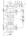
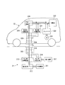
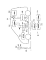
- FIG. 1 is a block diagram illustrating a main configuration of a mobile vehicle and a non-contact power transmission apparatus according to the first embodiment of the present invention.
- the non-contact power transmission apparatus 11 of the present embodiment is installed on the ground surface.
- the non-contact power transmission device 11 is an electric vehicle when the electric vehicle 12 as a moving vehicle traveling on the ground is stopped in a predetermined positional relationship (a positional relationship in which an electromagnetic coupling circuit described later is formed). 12 can transmit electric power (electric power for charging the storage battery 124) in a non-contact manner.
- the non-contact power transmission device 11 includes an external power source 111, a rectifier circuit 112, a power feeding circuit 113, a power feeding coil 114 (primary coil), and the like.
- the external power source 111 is a power source that supplies power necessary to generate power to be transmitted to the electric vehicle 12, and is a power source that supplies, for example, three-phase AC power having a voltage of 200 [V].
- the external power source 111 is not limited to a three-phase AC power source, and may be a power source that supplies single-phase AC power such as a commercial AC power source.
- the rectifier circuit 112 is a circuit that rectifies AC power supplied from the external power supply 111 and converts it into DC power.
- the rectifier circuit 112 can be omitted.
- the power feeding circuit 113 supplies the electric power supplied from the rectifying circuit 112 to the electric vehicle 12 in a non-contact manner through an electromagnetic coupling circuit formed by the power feeding coil 114 and the power receiving coil 125 provided in the electric vehicle 12. Specifically, the power supply circuit 113 realizes non-contact power supply to the electric vehicle 12 by converting the DC power from the rectifier circuit 112 into AC power and supplying the AC power to the power supply coil 114.
- the feeding coil 114 is a coil that is installed on the ground surface and feeds the AC power supplied from the feeding circuit 113 to the electric vehicle 12 in a non-contact manner.
- the power supply coil 114 and the power receiving coil 125 provided in the electric vehicle 12 are arranged in proximity to each other, thereby forming the electromagnetic coupling circuit.
- the electromagnetic coupling circuit means a circuit in which the power feeding coil 114 and the power receiving coil 125 are electromagnetically coupled and non-contact power feeding from the power feeding coil 114 to the power receiving coil 125 is performed.
- This electromagnetic coupling circuit may be either a circuit that supplies power by the “electromagnetic induction method” or a circuit that supplies power by the “electromagnetic resonance method”.
- an electric vehicle 12 as a moving vehicle includes a motor 121, an inverter 122, a contactor 123 (switch circuit), a storage battery 124, a power receiving coil 125 (secondary coil), a power receiving circuit 126, a charging device 127, and the like. It has. Among these, the storage battery 124 and the charging device 127 are connected to the DC bus 1B1, and the inverter 122, the power receiving circuit 126, and the charging device 127 are connected to the DC bus 1B2.
- the motor 121 is mounted on the electric vehicle 12 as a power generation source that generates power for moving the electric vehicle 12, and generates power according to the drive of the inverter 122.
- a motor such as a permanent magnet type synchronous motor or an induction motor can be used.
- the inverter 122 drives the motor 121 using electric power supplied from the storage battery 124 via the contactor 123 under the control of the control unit 132 (not shown in FIG. 1, refer to FIG. 2).
- the contactor 123 is provided between the DC bus 1B1 and the DC bus 1B2, and switches between connecting the DC bus 1B1 and the DC bus 1B2 to a disconnected state under the control of the control unit 132. Specifically, when discharging the power of the storage battery 124, the contactor 123 is controlled so that the DC bus 1B1 and the DC bus 1B2 are connected, whereby the storage battery 124 is connected to the inverter 122 and the power receiving circuit 126. Is done.
- the direct current bus 1B1 and the direct current bus 1B2 are controlled to be disconnected, whereby the storage battery 124, the inverter 122, and the power receiving circuit 126 are disconnected, and the motor is connected to the motor from the storage battery 124. 121 is electrically disconnected.
- the storage battery 124 is a rechargeable battery (for example, a secondary battery such as a lithium ion battery or a nickel metal hydride battery) mounted on the electric vehicle 12 and supplies power for driving the motor 121.
- the power receiving coil 125 is provided at the bottom of the electric vehicle 12 and is a coil for receiving power (AC power) supplied from the power supply coil 114 provided in the non-contact power transmission device 11 in a non-contact manner.
- AC power AC power supplied from the power supply coil 114 provided in the non-contact power transmission device 11 in a non-contact manner.
- the power receiving coil 125 comes close to the power feeding coil 114 of the non-contact power transmission device 11, the above-described electromagnetic coupling circuit is formed. That is, the power receiving coil 125 is configured to be able to transmit power in a contactless manner with the power feeding coil 114 outside the vehicle.
- the power receiving circuit 126 receives power (AC power) supplied in a non-contact manner through an electromagnetic coupling circuit formed by the power feeding coil 114 and the power receiving coil 125 of the non-contact power transmission device 11, and receives the received power. It is converted into DC power and supplied to the DC bus 1B2.
- the charging device 127 is a device that charges the storage battery 124 using power (DC power) supplied from the power receiving circuit 126 via the DC bus 1B2.
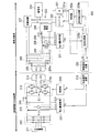
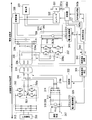
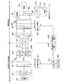
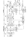
- FIG. 2 is a diagram showing in detail the electrical configuration of the mobile vehicle and the non-contact power transmission apparatus in the first embodiment of the present invention.
- the rectifier circuit 112 of the contactless power transmission device 11 described above is realized by a three-phase full-wave rectifier circuit (bridge rectifier circuit).
- the power feeding circuit 113 of the non-contact power transmission apparatus 11 has switching legs 1L1 and 1L2 (a circuit composed of two transistors connected in series and a diode connected in parallel to each of the two transistors) connected in parallel. It is realized with a circuit.
- two capacitors 114 a are provided between the power supply circuit 113 and the power supply coil 114.
- the capacitor 114a forms a series resonance circuit together with the feeding coil 114.
- One end of the feeding coil 114 is connected to the switching leg 1L1 of the feeding circuit 113 via one capacitor 114a, and the other end of the feeding coil 114 is connected to the switching leg 1L2 of the feeding circuit 113 via the other capacitor 114a. It is connected.
- the non-contact power transmission apparatus 11 includes a voltage measuring device 115, a current measuring device 116, a power amount calculator 117 (first power supply amount calculating unit), and a wireless communication device 118 in addition to the external power source 111 to the feeding coil 114 described above. (First device side output unit).
- the voltage measuring device 115 and the current measuring device 116 are provided between the rectifier circuit 112 and the power feeding circuit 113, and measure the input voltage V1 (t) and the input current I1 (t) of the power feeding circuit 113, respectively.
- the power amount calculator 117 uses the input voltage V1 (t) measured by the voltage measuring instrument 115 and the input current I1 (t) measured by the current measuring instrument 116 to supply power to the power feeding circuit 113.
- the amount P1 (first power supply amount) is obtained. Specifically, the electric energy P1 is calculated by multiplying V1 (t) and I1 (t). If the loss of the power supply circuit 113 and the power supply coil 114 is zero, the amount of power P1 supplied to the power supply circuit 113 is equal to the amount of power supplied from the power supply coil 114 (power supply amount).
- the power amount P ⁇ b> 1 indicates the amount of power that the power supply coil 114 supplies to the power reception coil 125.
- the wireless communication device 118 can wirelessly communicate various types of information with the wireless communication device 131 provided in the electric vehicle 12. For example, information indicating the power amount P ⁇ b> 1 obtained by the power amount calculator 117 is stored in the wireless communication device 131. Send.
- the wireless communication device 118 can communicate with the wireless communication device 131 when the wireless communication device 131 of the electric vehicle 12 is located in an area having a radius of about several meters with the installation position as a center.
- the power receiving circuit 126 of the electric vehicle 12 is realized by a bridge rectifier circuit including four diodes and a capacitor connected in parallel to the output terminal of the bridge rectifier circuit.
- a capacitor 125 a is connected in parallel between the power receiving coil 125 and the power receiving circuit 126, and a rotation angle detector 121 a such as a resolver or encoder that detects the rotation angle of the motor 121 is attached to the motor 121. .
- the electric vehicle 12 includes a voltage measuring device 128, a current measuring device 129, a power amount calculator 130 (first received power amount calculating unit), and a wireless communication device 131 (first vehicle side). Input unit) and a control unit 132.
- the voltage measuring device 128 and the current measuring device 129 are provided between the power receiving circuit 126 and the charging device 127 (DC bus 1B2 shown in FIG. 1), and the output voltage V2 (t) and the output current I2 of the power receiving circuit 126. (T) is measured respectively.
- the power amount calculator 130 uses the output voltage V2 (t) measured by the voltage measuring device 128 and the output current I2 (t) measured by the current measuring device 129 to obtain the power of the power received by the power receiving circuit 126.
- the amount P2 (first received power amount) is obtained. Specifically, the electric energy P2 is calculated by multiplying V2 (t) and I2 (t). If the loss of the power receiving coil 125 and the power receiving circuit 126 is zero, the power amount P2 of the power received by the power receiving circuit 126 is equal to the power amount (power received amount) of the power received by the power receiving coil 125.
- the power amount P ⁇ b> 2 indicates the amount of power received by the power receiving coil 125 from the power feeding coil 114.
- the wireless communication device 131 can perform wireless communication of various types of information with the wireless communication device 118 provided in the non-contact power transmission device 11. For example, the wireless communication device 131 receives information indicating the power amount P ⁇ b> 1 transmitted from the wireless communication device 118. . The wireless communication device 131 can communicate with the wireless communication device 118 when the wireless communication device 118 of the non-contact power transmission device 11 is located in an area having a radius of about several meters centered on itself.
- the control unit 132 controls the operation of the electric vehicle 12 by controlling each block shown in FIGS. For example, the traveling of the electric vehicle 12 is controlled by controlling the inverter 122 that drives the motor 121 while constantly monitoring the detection result of the rotation angle detector 121 a attached to the motor 121. In addition, when charging the storage battery 124, the control unit 132 refers to the power transmission efficiency ⁇ from the contactless power transmission device 11 to the electric vehicle 12 and stops at or near the installation location of the contactless power transmission device 11. The electric vehicle 12 that has been moved is moved (traveled) at a low speed, and the stop position of the electric vehicle 12 is adjusted.
- the control unit 132 adjusts the stopping position when charging the storage battery 124 described above, an efficiency calculator 132a (first efficiency calculation unit), a command value generator 132b (command generation unit), and a controller 132c. (Control unit).
- the efficiency calculator 132a transmits the electric power P2 obtained by the electric energy calculator 130 and the information indicating the electric energy P1 received by the wireless communication device 131 from the contactless power transmission device 11 to the electric vehicle 12.
- the power transmission efficiency ⁇ is calculated. Specifically, the power transmission efficiency ⁇ is calculated by dividing the power amount P2 by the power amount P1.
- the command value generator 132b generates a rotation angle command value for the motor 121 according to the power transmission efficiency ⁇ calculated by the efficiency calculator 132a.
- the controller 132c outputs a torque command value to the inverter 122 while monitoring the detection result of the rotation angle detector 121a based on the rotation angle command value generated by the command value generator 132b.
- the command value generator 132b is a command (rotation angle command value) for moving the electric vehicle 12 in an appropriate direction based on the power transmission efficiency ⁇ calculated by the efficiency calculator 132a using the power amount P1 and the power amount P2. ). In other words, the command value generator 132b generates a command for moving the electric vehicle 12 using the electric energy P1 and the electric energy P2.
- the command value generator 132b is configured to output the generated command to the controller 132c.
- the controller 132c is configured to output the motor based on the command (rotation angle command value) generated by the command value generator 132b.
- 121 is configured to be controllable.
- the rotation angle of the motor 121 and the amount of movement of the electric vehicle 12 are in a fixed relationship. Specifically, assuming that the tire radius is r and the reduction gear reduction ratio is n, the electric vehicle 12 moves by a distance (2 ⁇ r / n) when the motor rotates once. For this reason, the movement amount of the electric vehicle 12 can be controlled by controlling the rotation angle of the motor 121.
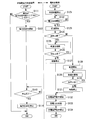
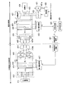
- FIG. 3 is a flowchart showing the operation of the mobile vehicle and the non-contact power transmission apparatus in the first embodiment of the present invention. In the following, an operation in the case where the storage battery 124 mounted mainly on the electric vehicle 12 is charged using the power supplied from the non-contact power transmission device 11 will be described.
- the user drives the electric vehicle 12 and moves the electric vehicle 12 to or near the place where the non-contact power transmission device 11 is installed.
- the non-contact power transmission device 11 determines whether or not the vehicle (electric vehicle 12) is within the power transmission possible area (step S111). For example, it is determined whether or not the electric vehicle 12 is within the power transferable area based on whether or not the wireless communication device 118 of the non-contact power transmission device 11 can wirelessly communicate with the wireless communication device 131 of the electric vehicle 12. To do.
- step S111 When it is determined that the electric vehicle 12 is not within the power transferable area (when the determination result of step S111 is “NO”), the series of processes of the non-contact power transmission apparatus 11 illustrated in FIG. On the other hand, when it is determined that the electric vehicle 12 is within the power transferable area (when the determination result of step S111 is “YES”), the non-contact power transmission device 11 operates the power supply circuit 113. Transmission of power is started (step S112). When the electric vehicle 12 is in an area where power can be transmitted, an electromagnetic coupling circuit is formed by the power supply coil 114 of the non-contact power transmission device 11 and the power receiving coil 125 of the electric vehicle 12.
- the control unit 132 When the user gives a charge instruction to the electric vehicle 12 after the electric vehicle 12 is moved to or near the place where the non-contact power transmission device 11 is installed and stopped, the control unit 132 first controls the contactor 123. Then, the DC bus 1B1 and the DC bus 1B2 are disconnected, and the power receiving circuit 126 is controlled to start the operation, while the charging device 127 is controlled to stop the operation (step S121). Next, a control part judges whether the electric power transmission from the non-contact electric power transmission apparatus 11 was started (step S122). For example, it is determined whether a signal indicating the start of power transmission is transmitted from the wireless communication device 118 of the non-contact power transmission device 11.
- step S122 When it is determined that power transmission has not started (when the determination result of step S122 is “NO”), the control unit 132 repeats the above determination. On the other hand, when it is determined that the power transmission has been started (when the determination result of step S122 is “YES”), the control unit 132 controls the inverter 122 to start the forward movement of the electric vehicle 12 (step). S123). At this time, the power transmitted from the non-contact power transmission device 11 is used as power for driving the motor 121.
- the control unit 132 determines whether or not the power transmission efficiency ⁇ calculated by the efficiency calculator 132a is increased by the forward movement of the electric vehicle 12 ( Step S124). When it is determined that the power transmission efficiency ⁇ has increased (when the determination result in step S124 is “YES”), the control unit 132 controls the inverter 122 to continue the low-speed advance of the electric vehicle 12 (step S125). . Subsequently, the control unit 132 determines again whether or not the power transmission efficiency ⁇ calculated by the efficiency calculator 132a has increased due to the forward movement of the electric vehicle 12 (step S126).
- step S126 When it is determined that the power transmission efficiency ⁇ has increased (when the determination result in step S126 is “YES”), the control unit 132 controls the inverter 122 to continue the low-speed advance of the electric vehicle 12 (step S125). On the other hand, when it is determined that the power transmission efficiency ⁇ does not increase (when the determination result in step S126 is “NO”), the control unit 132 controls the inverter 122 to stop the electric vehicle 12 (step S127). . At the time of this stop, the relative position of the power receiving coil 125 with respect to the power feeding coil 114 is adjusted to a position suitable for non-contact power transmission.
- step S124 the control unit 132 (command value generator 132b) controls the inverter 122 to start the reverse drive of the electric vehicle 12 (step S128). Subsequently, the control unit 132 continues the low-speed backward movement of the electric vehicle 12 (step S129), and determines whether or not the power transmission efficiency ⁇ calculated by the efficiency calculator 132a has increased due to the reverse movement (step S130).
- step S130 When it is determined that the power transmission efficiency ⁇ has increased (when the determination result of step S130 is “YES”), the control unit 132 controls the inverter 122 to continue the low-speed backward movement of the electric vehicle 12 (step S129). . On the other hand, when it is determined that the power transmission efficiency ⁇ does not increase (when the determination result of step S130 is “NO”), the control unit 132 controls the inverter 122 to stop the electric vehicle 12 (step S131). ). At the time of this stop, the relative position of the power receiving coil 125 with respect to the power feeding coil 114 is adjusted to a position suitable for non-contact power transmission.
- step S133 the control unit 132 controls the charging device 127 to start the operation and controls the inverter 122 to stop the operation (step S132).
- the storage battery 124 is charged (step S133).
- AC power from the non-contact power transmission device 11 is transmitted to the electric vehicle 12 in a non-contact manner through an electromagnetic coupling circuit formed by the power feeding coil 114 and the power receiving coil 125 and is received by the power receiving circuit 126.
- the AC power received by the power receiving circuit 126 is converted into DC power, and the converted DC power is supplied to the charging device 127.
- charging of the storage battery 124 using this direct current is performed by the charging device 127.
- the control unit 132 stops the charging device 127 and stops charging the storage battery 124 (step S134).
- the non-contact power transmission apparatus 11 determines whether or not charging of the storage battery 124 mounted on the electric vehicle 12 is completed after starting transmission of power in step S112 (step S113). For example, it is determined whether a signal indicating completion of charging of the storage battery 124 has been transmitted from the wireless communication device 131 of the electric vehicle 12. When it is determined that the charging is not completed (when the determination result of step S113 is “NO”), the non-contact power transmission apparatus 11 repeats the above determination. On the other hand, when it is determined that the charging is completed (when the determination result of step S113 is “YES”), the non-contact power transmission device 11 stops the power feeding circuit 113 to stop power transmission (step S113). S114).
- the power transmission efficiency ⁇ from the contactless power transmission device 11 to the electric vehicle 12 is obtained, and the electric vehicle 12 is moved back and forth while referring to the power transmission efficiency ⁇ , so that contactlessness is achieved.
- the positions of the feeding coil 114 of the power transmission device 11 and the receiving coil 125 of the electric vehicle 12 are adjusted. For this reason, even if it is the electric vehicle 12 from which the magnitude
- a mechanism for moving the power feeding coil 114 and the power receiving coil 125 independently is not required, there is no increase in size and cost.
- the power transmission efficiency ⁇ is not only the power transmission efficiency between the power feeding coil 114 and the power receiving coil 125 but also the power transmission efficiency including the power feeding circuit 113 and the power receiving circuit 126, and is substantially the same as the actual power transmission efficiency. It is. For this reason, the position of the power feeding coil 114 of the non-contact power transmission device 11 and the power receiving coil 125 of the electric vehicle 12 can be adjusted to a more appropriate position so that the actual power transmission efficiency is maximized.
- the contactless power transmission device 11 when the electric vehicle 12 is moved back and forth to adjust the position of the power supply coil 114 of the non-contact power transmission device 11 and the power reception coil 125 of the electric vehicle 12, the contactless power transmission device 11 The transmitted power is used as power for driving the motor 121. For this reason, even if the remaining capacity of the storage battery 124 is zero, the above position adjustment can be performed.
- the electric vehicle 12 is moved back and forth while referring to the power transmission efficiency ⁇ from the contactless power transmission device 11 to the electric vehicle 12, but the position adjustment is performed.
- the position adjustment may be performed by moving the electric vehicle 12 back and forth while referring to the power amount P2 (the power received by the power receiving circuit 126) obtained by the power amount calculator 130.
- the command value generator 132b generates a rotation angle command value as a command for moving the electric vehicle 12 using the power amount P2 obtained by the power amount calculator 130, and the rotation angle command value is obtained. You may be comprised so that it may output to the controller 132c.
- the non-contact power transmission device 11 and the feeding coil 114 do not need to be installed in exact agreement with the ground surface.
- the contactless power transmission efficiency may be embedded within a range that does not significantly decrease and may be installed lower than the ground surface, or may be installed within a range that does not significantly interfere with the running of the electric vehicle 12 and installed higher than the ground surface. .
- the case where the position adjustment is performed by moving the electric vehicle 12 back and forth has been described as an example.
- the vehicle moves in the left-right direction.
- the moving vehicle can move only forward and backward unless the steering is operated, and generally cannot move linearly in the left-right direction. For this reason, it is desirable to use a power feeding coil that does not cause a significant decrease in transmission efficiency even when a lateral displacement occurs.
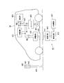
- FIG. 4 is a diagram showing an installation example of a feeding coil suitable for use in the non-contact power transmission apparatus according to the first embodiment of the present invention.
- the feeding coil 114 of the non-contact power transmission device 11 is a coil having a rectangular shape in plan view.
- the longitudinal direction is perpendicular to the lane marking W, and from the car stop ST. It is installed between the lane markings W so as to be separated by about 1 meter. Since the power transmission possible area of the feeding coil 114 installed in this way is long in the direction orthogonal to the lane marking W, even if there is a slight shift in the left-right direction of the electric vehicle 12 between the lane markings W, the transmission efficiency Can be prevented.
- the electric vehicle 12 when the position adjustment is performed, the electric vehicle 12 is continuously moved forward or backward, but may be intermittent movement over a minute distance instead of continuous movement.
- the received power is used as the power for driving the motor 121. Therefore, the output current I2 (t) flows and the power transmission efficiency ⁇ can be obtained. .
- the power transmission efficiency ⁇ cannot be obtained.
- the charging device 127 is stopped and the motor 121 is driven to move the minute distance, and after stopping, the charging device 127 is operated to charge the storage battery 124. Repeat the operation. Accordingly, since the received power is used for charging the storage battery 124 during the stop, the power transmission efficiency ⁇ can be obtained even during the stop. Whether the power transmission efficiency ⁇ is increasing or decreasing is determined by comparing the power transmission efficiency ⁇ before the intermittent movement with the power transmission efficiency ⁇ after one intermittent operation.
- the wireless communication apparatus 118 of the non-contact power transmission device 11 determines whether or not the electric vehicle 12 is in the power transmission possible area. And whether or not wireless communication is possible. However, based on the position of the electric vehicle 12 obtained by GPS (Global Positioning System) or the like, it may be determined whether or not the electric vehicle 12 is in the power transferable area.
- GPS Global Positioning System
- the electric vehicle 12 can transmit power.
- the electric vehicle 12 may be stopped immediately after entering the area. That is, the electric vehicle 12 may be stopped so that the power receiving coil 125 is disposed near the outer edge of the power transferable area. Thereby, if the electric vehicle 12 is moved forward, the power transmission efficiency ⁇ increases and the determination result in step S124 in FIG. 3 is always “YES”, so that the electric vehicle 12 can be prevented from moving backward. .
- the control unit 132 of the electric vehicle 12 performs control to stop the electric vehicle 12 via the wireless communication device 131. It is desirable to notify the non-contact power transmission device 11 that the power transmission efficiency ⁇ has significantly decreased and stop the transmission of power. Thereby, it is possible to prevent an unexpected abnormality that occurs during the position adjustment.
- the present invention can also be applied to a plug-in hybrid vehicle and can also be applied to a transport vehicle. Can do. Furthermore, the present invention can be applied to an unmanned mobile vehicle.
- FIG. 5 is a block diagram showing the main configuration of the mobile vehicle and the non-contact power transmission apparatus in the second embodiment of the present invention.
- the non-contact power transmission device 21 of the present embodiment is installed on the ground surface.
- the non-contact power transmission device 21 is configured such that when the electric vehicle 22 as a moving vehicle traveling on the ground is stopped in a predetermined positional relationship (a positional relationship in which an electromagnetic coupling circuit described later is formed), 22 can transmit power (power for charging the storage battery 224) in a non-contact manner.
- the non-contact power transmission device 21 includes an external power source 211, a rectifier circuit 212, a power feeding circuit 213, a power feeding coil 214 (primary coil), and the like.
- the external power supply 211 is a power supply that supplies power necessary to generate power to be transmitted to the electric vehicle 22, and is a power supply that supplies, for example, three-phase AC power having a voltage of 200 [V].
- the external power source 211 is not limited to a three-phase AC power source, and may be a power source that supplies single-phase AC power such as a commercial AC power source.
- the rectifier circuit 212 is a circuit that rectifies AC power supplied from the external power supply 211 and converts it into DC power.
- the rectifier circuit 212 can be omitted.
- the power supply circuit 213 supplies the electric power supplied from the rectifier circuit 212 to the electric vehicle 22 in a non-contact manner through an electromagnetic coupling circuit formed by the power supply coil 214 and the power receiving coil 225 provided in the electric vehicle 22. Specifically, the power supply circuit 213 realizes non-contact power supply to the electric vehicle 22 by converting the DC power from the rectifier circuit 212 into AC power and supplying the AC power to the power supply coil 214.
- the power supply coil 214 is installed on the ground surface and is a coil for supplying AC power supplied from the power supply circuit 213 to the electric vehicle 22 in a non-contact manner.
- the power supply coil 214 and the power receiving coil 225 provided in the electric vehicle 22 are arranged in proximity to each other, thereby forming the electromagnetic coupling circuit.
- the electromagnetic coupling circuit means a circuit in which the power feeding coil 214 and the power receiving coil 225 are electromagnetically coupled and non-contact power feeding from the power feeding coil 214 to the power receiving coil 225 is performed.
- This electromagnetic coupling circuit may be either a circuit that supplies power by the “electromagnetic induction method” or a circuit that supplies power by the “electromagnetic resonance method”.
- the electric vehicle 22 as a moving vehicle includes a motor 221, an inverter 222, a contactor 223, a storage battery 224, a power receiving coil 225 (secondary coil), a power receiving circuit 226, a charging device 227, and a load device 228 (first). 1 load device).
- the electric vehicle 22 has a function of automatically adjusting the position of the power receiving coil 225 with respect to the power feeding coil 214 of the contactless power transmission device 21.
- the inverter 222, the storage battery 224, and the charging device 227 are connected to the DC bus 2B1, and the contactor 223, the power receiving circuit 226, and the charging device 227 are connected to the DC bus 2B2.
- the contactor 223 and the charging device 227 constitute power supply destination setting means in this embodiment.
- the motor 221 is mounted on the electric vehicle 22 as a power generation source that generates power for moving the electric vehicle 22, and generates power according to the drive of the inverter 222.
- a motor such as a permanent magnet type synchronous motor or an induction motor can be used.
- the inverter 222 drives the motor 221 using the power supplied from the storage battery 224 under the control of the control unit 233 (not shown in FIG. 5, see FIG. 6).
- the contactor 223 is provided between the load device 228 and the DC bus 2B2, that is, between the power receiving circuit 226 and the load device 228, and is connected to the power receiving circuit 226 and the load device 228 under the control of the control unit 233. And switch between disconnected states. Specifically, the contactor 223 is closed to connect the power receiving circuit 226 and the load device 228 when the position of the power receiving coil 225 with respect to the power feeding coil 214 is adjusted, and after the position adjustment is completed, the contactor 226 and the load device 228 are closed. To open.
- the storage battery 224 is a rechargeable battery (for example, a secondary battery such as a lithium ion battery or a nickel metal hydride battery) mounted on the electric vehicle 22, and supplies power for driving the motor 221.
- the power receiving coil 225 is provided at the bottom of the electric vehicle 22 and is a coil for receiving power (AC power) supplied from the power supply coil 214 provided in the non-contact power transmission device 21 in a non-contact manner.
- AC power AC power supplied from the power supply coil 214 provided in the non-contact power transmission device 21 in a non-contact manner.
- the power receiving coil 225 comes close to the power feeding coil 214 of the non-contact power transmission device 21, the above-described electromagnetic coupling circuit is formed. That is, the power receiving coil 225 is configured to be able to transmit power in a non-contact manner with the power feeding coil 214 outside the vehicle.
- the power receiving circuit 226 receives power (AC power) supplied in a non-contact manner through an electromagnetic coupling circuit formed by the power feeding coil 214 and the power receiving coil 225 of the non-contact power transmission device 21 and receives the received power. It is converted into DC power and supplied to the DC bus 2B2.
- the charging device 227 is a device that charges the storage battery 224 using power (DC power) supplied from the power reception circuit 226 via the DC bus 2B2.
- the load device 228 is connected to the DC bus 2B2 via the contactor 223.
- Such a load device 228 is a resistor having a predetermined resistance value, for example, and consumes DC power supplied from the power receiving circuit 226 when connected to the power receiving circuit 226 by the contactor 223.
- FIG. 6 is a diagram showing in detail the electrical configuration of the mobile vehicle and the non-contact power transmission device in the second embodiment of the present invention.
- the rectifier circuit 212 of the non-contact power transmission device 21 described above is realized by a three-phase full-wave rectifier circuit (bridge rectifier circuit).
- the power feeding circuit 213 of the non-contact power transmission device 21 has switching legs 2L1 and 2L2 (a circuit composed of two transistors connected in series and a diode connected in parallel to each of these two transistors) connected in parallel. It is realized by a circuit (inverter).
- As the transistor an IGBT (Insulated Gate Bipolar Transistor) or a power MOSFET (Metal-Oxide-Semiconductor Field-Effect Transistor) can be used.
- two capacitors 214 a are provided between the power supply circuit 213 and the power supply coil 214.
- the capacitor 214a forms a series resonance circuit together with the feeding coil 214.
- One end of the feeding coil 214 is connected to the switching leg 2L1 of the feeding circuit 213 via one capacitor 214a, and the other end of the feeding coil 214 is connected to the switching leg 2L2 of the feeding circuit 213 via the other capacitor 214a. It is connected.
- the non-contact power transmission device 21 includes a voltage measuring device 215, a current measuring device 216, a power amount calculator 217 (first power supply amount calculation unit), a wireless communication device 218 ( 1st apparatus side input part, 1st apparatus side output part), and the control part 219 are provided.
- the voltage measuring device 215 and the current measuring device 216 are provided between the rectifier circuit 212 and the power feeding circuit 213, and measure the input voltage V1 (t) and the input current I1 (t) of the power feeding circuit 213, respectively.
- the power amount calculator 217 uses the input voltage V1 (t) measured by the voltage measuring device 215 and the input current I1 (t) measured by the current measuring device 216 to power the power supplied to the power feeding circuit 213.
- the amount P1 (first power supply amount) is obtained. Specifically, the electric energy P1 is calculated by multiplying V1 (t) and I1 (t). If the loss of the power supply circuit 213 and the power supply coil 214 is zero, the power amount P1 of power supplied to the power supply circuit 213 is equal to the power amount of power supplied from the power supply coil 214 (power supply amount).
- the power amount P ⁇ b> 1 indicates the amount of power that the power supply coil 214 supplies power to the power reception coil 225.
- the wireless communication device 218 can wirelessly communicate various types of information with the wireless communication device 232 provided in the electric vehicle 22. For example, information indicating the power amount P 1 obtained by the power amount calculator 217 is stored in the wireless communication device 232. And a position adjustment completion notification N (described later) output from the controller 233c is received.
- the wireless communication device 218 can communicate with the wireless communication device 232 when the wireless communication device 232 of the electric vehicle 22 is located in an area having a radius of about several meters with the installation position as a center.
- the control unit 219 controls the power feeding circuit 213 according to communication between the wireless communication device 218 and the wireless communication device 232. That is, the control unit 219 increases the power that the power feeding circuit 213 outputs to the power feeding coil 214 to a very small amount according to a signal (position adjustment completion notification N described later) received by the wireless communication device 218 from the wireless communication device 232. Switch to power.
- the power receiving circuit 226 of the electric vehicle 22 is realized by a bridge rectifier circuit including four diodes and a capacitor connected in parallel to the output terminal of the bridge rectifier circuit.
- a capacitor 225 a is connected in parallel between the power receiving coil 225 and the power receiving circuit 226, and a rotation angle detector 221 a such as a resolver or encoder that detects the rotation angle of the motor 221 is attached to the motor 221. .
- the electric vehicle 22 includes a voltage measuring device 229, a current measuring device 230, an electric energy calculator 231 (first received electric energy calculating unit), and a wireless communication device 232 (first vehicle side).
- the voltage measuring device 229 and the current measuring device 230 are provided between the power receiving circuit 226 and the load device 228.
- the voltage measuring device 229 and the current measuring device 230 receive the input voltage V2 (t) and the input current I2 (t) from the power receiving circuit 226 to the load device 228. Measure each.
- the power amount calculator 231 uses the input voltage V ⁇ b> 2 (t) measured by the voltage measuring device 229 and the input current I ⁇ b> 2 (t) measured by the current measuring device 230 to obtain the power of the power received by the power receiving circuit 226.
- the amount P2 is obtained. That is, the power amount calculator 231 obtains the power amount P2 (first power receiving amount) received by the power receiving circuit 226 when the supply destination of the power received by the power receiving coil 225 is set to the load device 228. It is configured. Specifically, the electric energy P2 is calculated by multiplying V2 (t) and I2 (t).
- the power amount P2 of the power received by the power receiving circuit 226 is equal to the power amount (power received amount) of the power received by the power receiving coil 225.
- the amount of power P2 indicates the amount of power received by the power receiving coil 225 from the power feeding coil 214.
- the wireless communication device 232 can wirelessly communicate various information with the wireless communication device 218 provided in the non-contact power transmission device 21. For example, the wireless communication device 232 receives information indicating the power amount P ⁇ b> 1 transmitted from the wireless communication device 218. , A position adjustment completion notification N (described later) output from the controller 233c is transmitted. The wireless communication device 232 can communicate with the wireless communication device 218 when the wireless communication device 218 of the non-contact power transmission device 21 is located in an area having a radius of about several meters centered on itself.
- the control unit 233 controls the operation of the electric vehicle 22 by controlling each block shown in FIGS.
- the running of the electric vehicle 22 is controlled by controlling the inverter 222 that drives the motor 221 while constantly monitoring the detection result of the rotation angle detector 221a attached to the motor 221.
- the control unit 233 stops at or near the installation location of the non-contact power transmission device 21 while referring to the power transmission efficiency ⁇ from the non-contact power transmission device 21 to the electric vehicle 22.
- the electric vehicle 22 that has been moved is moved (traveled) at a low speed, and the stop position of the electric vehicle 22 is adjusted.
- the control unit 233 has an efficiency calculator 233a (first efficiency calculation unit), a command value generator 233b, and a controller 233c (command generation unit, A control unit).
- the efficiency calculator 233a is based on the power amount P2 obtained by the power amount calculator 231 and information indicating the power amount P1 received by the wireless communication device 232 when the positions of the power feeding coil 214 and the power receiving coil 225 are adjusted.
- the power transmission efficiency ⁇ from the non-contact power transmission device 21 to the electric vehicle 22 is calculated.
- the power transmission efficiency ⁇ is calculated by dividing the power amount P2 by the power amount P1.
- the command value generator 233b generates a rotation angle command value for the motor 221 in accordance with the power transmission efficiency ⁇ calculated by the efficiency calculator 233a.
- the controller 233c outputs a torque command value to the inverter 222 while monitoring the detection result of the rotation angle detector 221a based on the rotation angle command value generated by the command value generator 233b.
- the controller 233c generates an internal command for moving the electric vehicle 22 in an appropriate direction based on the power transmission efficiency ⁇ calculated by the efficiency calculator 233a using the power amount P1 and the power amount P2.
- the motor 221 is configured to be controlled via the inverter 222 based on the command. That is, the controller 233c has two functions of a command generation unit and a control unit in the present invention.
- the command value generator 233b as the command generation unit generates a command for moving the electric vehicle 22 using the power amount P1 and the power amount P2.
- the command value generator 233b may have a function as a command generation unit in the present invention.
- the controller 233c controls the contactor 223 so that the power receiving circuit 226 and the load device 228 are connected. Further, the controller 233c controls the contactor 223 at a timing when the power transmission efficiency ⁇ calculated by the efficiency calculator 233a changes from increasing to constant or decreasing, thereby disconnecting the power receiving circuit 226 and the load device 228 from each other.
- the adjustment completion notification N is output to the wireless communication device 232.
- the rotation angle of the motor 221 and the amount of movement of the electric vehicle 22 are in a fixed relationship. Specifically, assuming that the tire radius is r and the reduction gear reduction ratio is n, the electric vehicle 22 moves by a distance (2 ⁇ r / n) when the motor rotates once. For this reason, the movement amount of the electric vehicle 22 can be controlled by controlling the rotation angle of the motor 221.
- FIG. 7 is a flowchart showing operations of the moving vehicle and the non-contact power transmission apparatus in the second embodiment of the present invention. In the following, the operation when the storage battery 224 mounted mainly on the electric vehicle 22 is charged using the power supplied from the non-contact power transmission device 21 will be described.
- the driver drives the electric vehicle 22 and moves the electric vehicle 22 to or near the place where the non-contact power transmission device 21 is installed.
- the control unit 219 of the non-contact power transmission device 21 determines whether or not the vehicle (electric vehicle 22) is within the power transmission possible area (step S211). For example, the control unit 219 determines whether or not the electric vehicle 22 is in the power transferable area depending on whether or not the wireless communication device 218 can wirelessly communicate with the wireless communication device 232 of the electric vehicle 22.
- control unit 219 determines that the electric vehicle 22 is not within the power transferable area (when the determination result of step S211 is “NO”), the control unit 219 performs a series of steps of the non-contact power transmission device 21 illustrated in FIG. The process ends.
- the control unit 219 determines that the electric vehicle 22 is in the power transferable area (when the determination result in step S211 is “YES”), the control unit 219 operates the power supply circuit 213 to generate a small amount of power. Is started (step S212).
- an electromagnetic coupling circuit is formed by the feeding coil 214 of the non-contact power transmission device 21 and the receiving coil 225 of the electric vehicle 22.
- the driver moves the electric vehicle 22 to or near the place where the non-contact power transmission device 21 is installed and stops the vehicle, and then gives a charging instruction to an operation device (not shown) of the electric vehicle 22.
- the controller 233c of the electric vehicle 22 closes the contactor 223 to place the power receiving circuit 226 and the load device 228 in a connected state, and controls the power receiving circuit 226 to start the power receiving operation while charging.
- the device 227 is controlled to stop the operation (step S221).
- the controller 233 c switches the power supply destination of the power receiving circuit 226 from the charging device 227 to the load device 228 when the position adjustment of the power receiving coil 225 with respect to the power feeding coil 214 is started.
- the load on the power receiving circuit 226 of the load device 228 is significantly lighter than that of the charging device 227. Therefore, in step S212, the control unit 219 supplies minute electric power to the electric vehicle 22 that is significantly smaller than the electric power supplied to the electric vehicle 22 in a state where the power supply destination of the power receiving circuit 226 is set to the charging device 227.
- the power supply circuit 213 is operated so as to supply power.
- the controller 233c determines whether or not the power transmission of the minute power from the non-contact power transmission device 21 is started (step S222). For example, it is determined whether a signal indicating the start of power transmission has been transmitted from the wireless communication device 218 of the non-contact power transmission device 21. The controller 233c repeats the above determination when determining that the power transmission is not started (when the determination result of step S222 is “NO”). On the other hand, when controller 233c determines that power transmission has started (when the determination result of step S222 is “YES”), it controls inverter 222 to start the forward movement of electric vehicle 22 (step S22). S223). At this time, the inverter 222 drives the motor 221 using electric power supplied from the storage battery 224.
- the controller 233c when starting the forward movement of the electric vehicle 22, determines whether or not the power transmission efficiency ⁇ calculated by the efficiency calculator 233a has increased due to the forward movement of the electric vehicle 22 (step S224). When controller 233c determines that power transmission efficiency ⁇ has increased (when the determination result in step S224 is “YES”), controller 233c controls inverter 222 to continue the low-speed advance of electric vehicle 22 (step S225). ). Subsequently, the controller 233c determines again whether or not the power transmission efficiency ⁇ calculated by the efficiency calculator 233a has increased due to the forward movement of the electric vehicle 22 (step S226).
- controller 233c determines that power transmission efficiency ⁇ has increased (when the determination result in step S226 is “YES”), controller 233c controls inverter 222 to continue the low-speed advance of electric vehicle 22 (step S225). ). In contrast, when controller 233c determines that power transmission efficiency ⁇ does not increase (when the determination result of step S226 is “NO”), controller 233c controls inverter 222 to stop electric vehicle 22 (step S226). S227). That is, the controller 233c stops the electric vehicle 22 when the electric vehicle 22 is moving forward and the power transmission efficiency ⁇ changes from increasing to constant or decreasing. At the time of this stop, the relative position of the power receiving coil 225 with respect to the power feeding coil 214 is adjusted to a position suitable for non-contact power transmission.
- step S224 determines that the power transmission efficiency ⁇ calculated by the efficiency calculator 233a does not increase due to the advancement of the electric vehicle 22 immediately after the electric vehicle 22 starts to advance (the determination result of step S224). Is "NO"), the inverter 222 is controlled to start the reverse of the electric vehicle 22 (step S228). Subsequently, the controller 233c continues the low speed reverse of the electric vehicle 22 (step S229), and determines whether or not the power transmission efficiency ⁇ calculated by the efficiency calculator 233a has increased due to the reverse (step S230).
- controller 233c determines that power transmission efficiency ⁇ has increased (when the determination result in step S230 is “YES”), controller 233c controls inverter 222 to continue the low-speed backward movement of electric vehicle 22 (step S229). ). In contrast, when controller 233c determines that power transmission efficiency ⁇ does not increase (when the determination result in step S230 is “NO”), it controls inverter 222 to stop electric vehicle 22 (step S230). S231). That is, the controller 233c stops the electric vehicle 22 when the electric vehicle 22 moves backward and the power transmission efficiency ⁇ changes from increasing to constant or decreasing. At the time of this stop, the relative position of the power receiving coil 225 with respect to the power feeding coil 214 is adjusted to a position suitable for non-contact power transmission.
- the controller 233c opens the contactor 223 and disconnects the power receiving circuit 226 and the load device 228. Further, the controller 233c causes the wireless communication device 232 to transmit a position adjustment completion notification N for notifying that the position adjustment is completed, the electric vehicle 22 is stopped, and the contactor 223 is in a disconnected state (open state) (Step 233). S232). That is, the controller 233c switches the power supply destination of the power receiving circuit 226 from the load device 228 to the charging device 227. Subsequently, after step S232, the controller 233c controls the charging device 227 to start the charging operation, while controlling the inverter 222 to stop the operation (step S233).
- the storage battery 224 is charged by the charging device 227 (step S234).
- AC power from the non-contact power transmission device 21 is transmitted in a non-contact manner to the electric vehicle 22 through an electromagnetic coupling circuit formed by the power feeding coil 214 and the power receiving coil 225 and is received by the power receiving circuit 226.
- the AC power received by the power receiving circuit 226 is converted into DC power, and the converted DC power is supplied to the charging device 227. Therefore, the charging device 227 charges the storage battery 224 using the direct current.
- the controller 233c stops the charging device 227 and stops charging of the storage battery 224 (step S235).
- the control unit 219 of the non-contact power transmission device 21 performs wireless communication with the position adjustment completion notification N (notification of the disconnection state of the contactor 223) described above by the wireless communication device 218 after starting transmission of minute power in step S212.
- the power supply circuit 213 is controlled to start transmission of the increased power for charging (high power for charging the storage battery 224) from the power supply coil 214 (step S213). That is, the control unit 219 switches the power transmitted from the power feeding coil 214 from a minute power to a large power for charging.
- the control unit 219 determines whether or not charging of the storage battery 224 mounted on the electric vehicle 22 is completed after starting transmission of the increased power for charging in step S213 (step S214). For example, the control unit 219 determines whether a signal indicating completion of charging of the storage battery 224 has been transmitted from the wireless communication device 232 of the electric vehicle 22. When the control unit 219 determines that the charging is not completed (when the determination result of step S214 is “NO”), the control unit 219 repeats the determination of step S214. On the other hand, when the control unit 219 determines that the charging is completed (when the determination result of step S214 is “YES”), the control unit 219 stops the power feeding circuit 213 to stop power transmission (step S215).
- the power transmission efficiency ⁇ from the contactless power transmission device 21 to the electric vehicle 22 is obtained, and the electric vehicle 22 is moved back and forth while referring to the power transmission efficiency ⁇ , so that contactlessness is achieved.
- the positions of the power feeding coil 214 of the power transmission device 21 and the power receiving coil 225 of the electric vehicle 22 are adjusted. For this reason, even if it is the electric vehicle 22 from which the magnitude
- the power transmission efficiency ⁇ is not only the power transmission efficiency between the power feeding coil 214 and the power receiving coil 225 but also the power transmission efficiency including the power feeding circuit 213 and the power receiving circuit 226, and is substantially the same as the actual power transmission efficiency. It is. For this reason, the position of the power feeding coil 214 of the non-contact power transmission device 21 and the power receiving coil 225 of the electric vehicle 22 can be adjusted to a more appropriate position so that the actual power transmission efficiency is maximized.
- the motor 221 is driven and controlled using the power of the storage battery 224 when the positions of the power feeding coil 214 and the power receiving coil 225 are adjusted. That is, the position adjustment is performed without using the power supplied from the power supply coil 214.
- it is not necessary to supply power for driving the motor 221 from the power supply coil 214, and it is sufficient to supply the minimum amount of power necessary for position adjustment. As a result, power loss that is not received by the receiving coil 225 out of the power output from the feeding coil 214 can be reduced.
- the position is adjusted by moving the electric vehicle 22 back and forth while referring to the power transmission efficiency ⁇ from the non-contact power transmission device 21 to the electric vehicle 22, but the power transmission efficiency ⁇
- the position adjustment may be performed by moving the electric vehicle 22 back and forth while referring to the power amount P2 (power received by the power receiving circuit 226) obtained by the power amount calculator 231.
- the controller 233c generates an internal command for moving the electric vehicle 22 in an appropriate direction using the electric energy P2 obtained by the electric energy calculator 231 and controls the motor 221 based on the command. You may be comprised so that it may control via the inverter 222. FIG.
- the non-contact power transmission device 21 and the feeding coil 214 do not have to be installed exactly on the ground surface.
- the contactless power transmission efficiency may be embedded within a range that does not significantly decrease and may be installed lower than the ground surface, or may be installed higher than the ground surface so as to protrude without significantly disturbing the running of the electric vehicle 22. .
- the position adjustment is performed by moving the electric vehicle 22 back and forth as an example.
- a moving vehicle that can move linearly in the left-right direction, It can be moved to adjust the position.
- the moving vehicle can move only forward and backward unless the steering is operated, and generally cannot move linearly in the left-right direction. For this reason, it is desirable to use a power feeding coil that does not cause a significant decrease in transmission efficiency even when a lateral displacement occurs.
- the power supply coil 214 of the non-contact power transmission device 21 may be arranged in the same configuration as the power supply coil 114 in FIG. 4 of the first embodiment described above.
- the electric vehicle 22 is continuously moved forward or backward when performing position adjustment, but may be intermittent movement over a minute distance instead of continuous movement. Whether the power transmission efficiency ⁇ is increasing or decreasing is determined by comparing the power transmission efficiency ⁇ before the intermittent movement with the power transmission efficiency ⁇ after one intermittent operation.
- the wireless communication device 218 of the non-contact power transmission device 21 determines whether or not the electric vehicle 22 is in the power transferable area. The determination is based on whether or not wireless communication with the device 232 is possible. However, based on the position of the electric vehicle 22 obtained by GPS (Global Positioning System) or the like, it may be determined whether or not the electric vehicle 22 is in the power transferable area.
- GPS Global Positioning System
- the electric vehicle 22 can transmit power.
- the electric vehicle 22 may be stopped immediately after entering the area. That is, the electric vehicle 22 may be stopped so that the power receiving coil 225 is disposed near the outer edge of the power transferable area. Accordingly, if the electric vehicle 22 is moved forward, the power transmission efficiency ⁇ increases and the determination result in step S224 in FIG. 7 is always “YES”, so that the electric vehicle 22 can be prevented from moving backward. .
- the controller 233c of the electric vehicle 22 performs control to stop the electric vehicle 22 and passes through the wireless communication device 232. It is desirable to notify the non-contact power transmission device 21 that the power transmission efficiency ⁇ has significantly decreased and stop power transmission. Thereby, it is possible to prevent an unexpected abnormality that occurs during the position adjustment.
- the present invention can also be applied to a plug-in hybrid vehicle and also applied to a transport vehicle. can do. Furthermore, the present invention can be applied to an unmanned mobile vehicle.
- the contactor 223 is used as means for switching the power supply path.
- an electronic switch such as a relay or FET (Field Effect Transistor) may be used instead of the contactor 223.
- the resistor was used as the load apparatus 228, if it is the load apparatus 228 which can consume micro electric power (about several watts), you may use an electronic load apparatus. For example, a part of minute electric power may be converted into a voltage by a converter and used as an auxiliary to a control power source of various devices (electronic load devices) inside the electric vehicle 22.
- the contactor 223 when the position is adjusted, the contactor 223 is connected (closed) and the charging device 227 is stopped. When the position adjustment is completed, the contactor 223 is disconnected (open) and charged. The device 227 is started to charge. Thereby, the supply destination of the electric power received by the power receiving coil 225 is switched to the load device 228 or the storage battery 224 (charging device 227).
- the present invention is not limited to this.
- a switch circuit for switching the connection destination of the power receiving circuit 226 to the charging device 227 or the load device 228 may be provided at a connection point between the load device 228 and the DC bus 2B2.
- the switch circuit switches the connection destination of the power receiving circuit 226 to the charging device 227 or the load device 228, the power supply destination received by the power receiving coil 225 can be switched to the load device 228 or the storage battery 224 (charging device 227). Good.
- the power receiving circuit 226 and the charging device 227 are in a disconnected state, so that it is not necessary to stop the charging device 227.
- the non-contact power transmission device 21 switches the power transmitted from the power supply coil 214 during the position adjustment and charging of the electric vehicle 22 to a minute power or a large power for charging.
- the present invention is not limited to this.
- the non-contact power transmission device 21 may continue to transmit a large amount of power for charging from the power supply coil 214 without switching the power transmitted from the power supply coil 214 during position adjustment and during charging.
- the electric vehicle 22 does not need to transmit the position adjustment completion notification N to the non-contact power transmission device 21.
- you may comprise an electric vehicle and a non-contact electric power transmission apparatus so that both the 1st and 2nd embodiment mentioned above can be implemented.
- the power supply destination used for vehicle position adjustment may be switched between the storage battery 224 and the load device 228 based on a predetermined condition.
- FIG. 8 is a block diagram showing the main configuration of the mobile vehicle and the non-contact power transmission apparatus in the third embodiment of the present invention.
- the non-contact power transmission device 31 of the present embodiment is installed on the ground surface.
- the non-contact power transmission device 31 is an electric vehicle when an electric vehicle 32 as a moving vehicle traveling on the ground is stopped in a predetermined positional relationship (a positional relationship in which an electromagnetic coupling circuit described later is formed). It is possible to transmit electric power (electric power for charging the storage battery 333) to 32 in a non-contact manner.
- the non-contact power transmission device 31 includes an external power source 311, a rectifier circuit 312, a ground side power feeding circuit 313, a ground side power receiving circuit 314, a ground side switch 315, a ground side coil 316 (primary side coil), and a load device 317 (second device). Load device).
- the external power supply 311 is a power supply that supplies power necessary to generate power to be transmitted to the electric vehicle 32, and is a power supply that supplies, for example, three-phase AC power having a voltage of 200 [V].
- the external power source 311 is not limited to a three-phase AC power source, and may be a power source that supplies single-phase AC power such as a commercial AC power source.
- the rectifier circuit 312 is a circuit that rectifies AC power supplied from the external power supply 311 and converts it into DC power. Note that a DC power source such as a fuel cell or a solar cell can be used as the external power source 311. In this case, the rectifier circuit 312 may be omitted and the DC power supply and the ground side power supply circuit 313 may be directly connected.
- the ground-side power supply circuit 313 converts the DC power supplied from the rectifier circuit 312 into AC power, and supplies the AC power to the ground-side coil 316 when connected to the ground-side coil 316 by the ground-side switch 315. To do. Thereby, the ground side power supply circuit 313 supplies electric power to the electric vehicle 32 in a non-contact manner via an electromagnetic coupling circuit formed by the ground side coil 316 and a vehicle side coil 334 provided in the electric vehicle 32 described later.
- the ground-side power receiving circuit 314 When the ground-side power receiving circuit 314 is connected to the ground-side coil 316 by the ground-side switch 315, the ground-side power receiving circuit 314 is contactless via an electromagnetic coupling circuit formed by the vehicle-side coil 334 and the ground-side coil 316 of the electric vehicle 32.
- the received power AC power
- the received power is converted into DC power and supplied to the load device 317.
- the ground side switch 315 selectively switches the connection destination of the ground side coil 316 to the ground side power feeding circuit 313 or the ground side power receiving circuit 314 under the control of the control unit 322 (not shown in FIG. 8, see FIG. 9).
- the ground side switch 315 an electronic switch using a semiconductor, or a mechanical contactor that physically moves a contact by a solenoid coil to switch between contact and non-contact can be used.
- the ground side switch 315 switches the connection destination of the ground side coil 316 to the ground side power receiving circuit 314 when the position of the vehicle side coil 334 of the electric vehicle 32 with respect to the ground side coil 316 is adjusted.
- the ground side switch 315 switches the connection destination of the ground side coil 316 to the ground side power supply circuit 313 when power is supplied to the electric vehicle 32 after the position adjustment is completed.
- the ground side coil 316 is installed on the ground surface, and both ends thereof are connected to the ground side switch 315.
- the ground side coil 316 generates an electromotive force by electromagnetic induction when an external magnetic field (a magnetic field generated by the vehicle side coil 334) acts.
- an external magnetic field a magnetic field generated by the vehicle side coil 334.
- the ground side coil 316 outputs the electromotive force to the ground side power receiving circuit 314 via the ground side switch 315.
- the ground side coil 316 is connected to the ground side power supply circuit 313 by the ground side switch 315, the ground side coil 316 is disposed in a state close to the vehicle side coil 334 provided in the electric vehicle 32. Contactless power feeding is performed to the vehicle-side coil 334 of the electric vehicle 32 using AC power supplied from the power feeding circuit 313 via the ground side switch 315.
- the ground side coil 316 and the vehicle side coil 334 provided in the electric vehicle 32 form an electromagnetic coupling circuit.
- the ground side coil 316 and the vehicle side coil 334 are electromagnetically coupled to each other so that the contactless power feeding from the ground side coil 316 to the vehicle side coil 334 or from the vehicle side coil 334 to the ground side coil 316 is performed.
- Means a circuit in which This electromagnetic coupling circuit may be either a circuit that supplies power by the “electromagnetic induction method” or a circuit that supplies power by the “electromagnetic resonance method”.
- the load device 317 is connected to the ground side power receiving circuit 314.
- Such a load device 317 is a resistor having a predetermined resistance value, for example, and consumes DC power supplied from the ground-side power receiving circuit 314.
- the electric vehicle 32 as a moving vehicle includes a motor 331, an inverter 332, a storage battery 333, a vehicle side coil 334 (secondary side coil), a vehicle side switch 335, a vehicle side power receiving circuit 336, and a vehicle side power supply circuit. 337, a charging device 338, and the like. Further, the electric vehicle 32 has a function of automatically adjusting the position of the vehicle side coil 334 with respect to the ground side coil 316 of the non-contact power transmission device 31.
- the motor 331 is mounted on the electric vehicle 32 as a power generation source that generates power for moving the electric vehicle 32, and generates power according to the drive of the inverter 332.
- a motor such as a permanent magnet type synchronous motor or an induction motor can be used.
- the inverter 332 drives the motor 331 using the power supplied from the storage battery 333 under the control of the control unit 343 (not shown in FIG. 8, refer to FIG. 9).
- the storage battery 333 is a rechargeable battery (for example, a secondary battery such as a lithium ion battery or a nickel metal hydride battery) mounted on the electric vehicle 32, and supplies power for driving the motor 331.
- the vehicle side coil 334 is provided at the bottom of the electric vehicle 32, and both ends thereof are connected to the vehicle side switch 335.
- the vehicle-side coil 334 generates an electromotive force by electromagnetic induction when an external magnetic field (magnetic field by the ground-side coil 316) is applied, and is connected to the vehicle-side power receiving circuit 336 by the vehicle-side switch 335.
- the electromotive force is output to the vehicle-side power receiving circuit 336 via 335.
- the vehicle-side coil 334 when the vehicle-side coil 334 is connected to the vehicle-side power supply circuit 337 by the vehicle-side switch 335, when AC power is supplied from the vehicle-side power supply circuit 337 via the vehicle-side switch 335, this AC power Is used to perform non-contact power supply to the ground coil 316 of the non-contact power transmission device 31. That is, the vehicle side coil 334 is configured to be able to transmit electric power in a non-contact manner with the ground side coil 316 outside the vehicle.
- the vehicle-side switch 335 selectively switches the connection destination of the vehicle-side coil 334 to the vehicle-side power receiving circuit 336 or the vehicle-side power feeding circuit 337 under the control of the control unit 343.
- the vehicle-side switch 335 an electronic switch using a semiconductor, or a mechanical contactor that physically moves a contact by a solenoid coil to switch between contact and non-contact can be used.
- the vehicle-side switch 335 switches the connection destination of the vehicle-side coil 334 to the vehicle-side power feeding circuit 337 when adjusting the position of the vehicle-side coil 334 with respect to the ground-side coil 316.
- the vehicle-side switch 335 switches the connection destination of the vehicle-side coil 334 to the vehicle-side power receiving circuit 336 when power is supplied to the electric vehicle 32 after the position adjustment is completed.
- the vehicle-side power receiving circuit 336 When the vehicle-side power receiving circuit 336 is connected to the vehicle-side coil 334 by the vehicle-side switch 335, the vehicle-side power receiving circuit 336 passes through an electromagnetic coupling circuit formed by the ground-side coil 316 and the vehicle-side coil 334 of the non-contact power transmission device 31. Then, the non-contact power (AC power) supplied is received, and the received power is converted to DC power and supplied to the charging device 338.
- AC power AC power
- the vehicle-side power supply circuit 337 converts the DC power supplied from the storage battery 333 into AC power, and supplies the AC power to the vehicle-side coil 334 when connected to the vehicle-side coil 334 by the vehicle-side switch 335.
- electric power is supplied to the non-contact power transmission device 31 in a non-contact manner through an electromagnetic coupling circuit formed by the vehicle-side coil 334 and the ground-side coil 316 of the non-contact power transmission device 31.
- the charging device 338 is a device that charges the storage battery 333 using electric power (DC power) supplied from the vehicle-side power receiving circuit 336.
- ground-side power feeding circuit 313, ground-side power receiving circuit 314, ground-side coil 316, vehicle-side coil 334, vehicle-side power receiving circuit 336, and vehicle-side power feeding circuit 337 are disclosed in, for example, Japan No. 225551 (“power transmission system”) or Japanese Patent Application Laid-Open No. 2008-236916 (“contactless power transmission device”).
- FIG. 9 is a diagram showing in detail the electrical configuration of the mobile vehicle and the non-contact power transmission device in one embodiment of the present invention.
- the rectifier circuit 312 of the non-contact power transmission device 31 described above is realized by a three-phase full-wave rectifier circuit (bridge rectifier circuit).
- the ground-side power supply circuit 313 of the non-contact power transmission device 31 includes switching legs 3L1 and 3L2 (a circuit including two transistors connected in series and a diode connected in parallel to each of the two transistors). This is realized by a circuit (inverter).
- An IGBT Insulated Gate Bipolar Transistor
- a power MOSFET Metal-Oxide-Semiconductor Field-Effect Transistor
- two capacitors 316a are provided between the ground side power supply circuit 313 and the ground side switch 315.
- the capacitor 316a forms a series resonance circuit together with the ground side coil 316 when connected to the ground side coil 316 via the ground side switch 315.
- the ground-side coil 316 is connected to the ground-side power supply circuit 313 by the ground-side switch 315, one end is connected to the switching leg 3L1 of the ground-side power supply circuit 313 via one capacitor 316a, and the other end Is connected to the switching leg 3L2 of the ground-side power feeding circuit 313 via the other capacitor 316a.
- the ground side power receiving circuit 314 is realized by a bridge rectifier circuit including four diodes and a capacitor connected in parallel to the output terminal of the bridge rectifier circuit.
- a capacitor 316b is connected in parallel between the ground-side power receiving circuit 314 and the ground-side switch 315.
- the non-contact power transmission device 31 includes a voltage measuring device 318, a current measuring device 319, a power amount calculator 320 (second received power amount calculating unit), and a wireless communication device 321 ( 1st apparatus side input part, 2nd apparatus side output part), and the control part 322 are provided.
- the voltage measuring device 318 and the current measuring device 319 are provided between the ground side power receiving circuit 314 and the load device 317, and measure the input voltage V1 (t) and the input current I1 (t) of the load device 317, respectively. To do.
- the electric energy calculator 320 uses the input voltage V1 (t) measured by the voltage measuring device 318 and the input current I1 (t) measured by the current measuring device 319 to receive power received by the ground-side power receiving circuit 314. Power amount P1 (second power receiving amount) is obtained. Specifically, the electric energy P1 is calculated by multiplying V1 (t) and I1 (t).
- the power amount P1 of the power received by the ground side power receiving circuit 314 is the power received by the ground side coil 316. Is equal to the amount of power (the amount of power received).
- the amount of power P1 indicates the amount of power received by the ground side coil 316 from the vehicle side coil 334.
- the wireless communication device 321 can wirelessly communicate various information with the wireless communication device 342 provided in the electric vehicle 32. For example, information indicating the power amount P1 obtained by the power amount calculator 320 is transmitted to the wireless communication device 342. The position adjustment completion notification N (described later) output from the controller 343c (described later) of the electric vehicle 32 is received.
- the wireless communication device 321 can communicate with the wireless communication device 342 when the wireless communication device 342 of the electric vehicle 32 is located in an area having a radius of about several meters with the installation position as a center.
- the control unit 322 controls the ground-side power supply circuit 313 and the ground-side switch 315 in accordance with communication between the wireless communication device 321 and the wireless communication device 342. That is, the control unit 322 controls the power output from the ground-side power supply circuit 313 to the ground-side coil 316 by controlling the ground-side power supply circuit 313 according to a signal received by the wireless communication device 321 from the wireless communication device 342. To do. Further, the control unit 322 switches the connection destination of the ground side coil 316 to the ground side power feeding circuit 313 or the ground side power receiving circuit 314 by controlling the ground side switch 315.
- the vehicle-side power receiving circuit 336 of the electric vehicle 32 is realized by a bridge rectifier circuit including four diodes and a capacitor connected in parallel to the output terminal of the bridge rectifier circuit.
- a capacitor 334a is connected in parallel between the vehicle-side power receiving circuit 336 and the vehicle-side switch 335, and a rotation angle detector 331a such as a resolver or encoder that detects the rotation angle of the motor 331 is attached to the motor 331. It has been.
- the vehicle-side power supply circuit 337 is a circuit (inverter) in which switching legs 3L1a and 3L2a (a circuit composed of two transistors connected in series and a diode connected in parallel to each of these two transistors) are connected in parallel. It has been realized.
- As the transistor an IGBT, a power MOSFET, or the like can be used as in the ground-side power feeding circuit 313 of the non-contact power transmission device 31.
- two capacitors 334b are provided between the vehicle-side power supply circuit 337 and the vehicle-side switch 335.
- the capacitor 334 b forms a series resonance circuit together with the vehicle side coil 334 when connected to the vehicle side coil 334 via the vehicle side switch 335.
- the vehicle-side coil 334 is connected to the vehicle-side power supply circuit 337 by the vehicle-side switch 335, one end is connected to the switching leg 3L1a of the vehicle-side power supply circuit 337 via one capacitor 334b, and the other end Is connected to the switching leg 3L2a of the ground-side power feeding circuit 313 via the other capacitor 334b.
- the electric vehicle 32 includes a voltage measuring device 339, a current measuring device 340, a power amount calculator 341 (second power supply amount calculating unit), and a wireless communication device 342 (second vehicle side).
- the voltage measuring device 339 and the current measuring device 340 are provided between the vehicle-side power supply circuit 337 and the storage battery 333, and measure the input voltage V2 (t) and the input current I2 (t) of the vehicle-side power supply circuit 337, respectively. To do.
- the power amount calculator 341 uses the input voltage V2 (t) measured by the voltage measuring device 339 and the input current I2 (t) measured by the current measuring device 340 to supply power to the vehicle-side power feeding circuit 337.
- Power amount P2 (second power supply amount) is obtained. Specifically, the electric energy P2 is calculated by multiplying V2 (t) and I2 (t).
- the amount of power P2 supplied to the vehicle side power supply circuit 337 is the power supplied from the vehicle side coil 334. Is equal to the amount of power (power supply amount).
- the power amount P2 indicates the amount of power that the vehicle side coil 334 supplies to the ground side coil 316.
- the wireless communication device 342 can wirelessly communicate various information with the wireless communication device 321 provided in the non-contact power transmission device 31, and receives, for example, information indicating the power amount P1 transmitted from the wireless communication device 321. , A position adjustment completion notification N (described later) output from the controller 343c is transmitted.
- the wireless communication device 342 can communicate with the wireless communication device 321 when the wireless communication device 321 of the non-contact power transmission device 31 is located in an area having a radius of about several meters centering on itself.
- the control unit 343 controls the operation of the electric vehicle 32 by controlling each block shown in FIGS.
- the traveling of the electric vehicle 32 is controlled by controlling the inverter 332 that drives the motor 331 while constantly monitoring the detection result of the rotation angle detector 331a attached to the motor 331.
- the control unit 343 refers to a power transmission efficiency ⁇ (described later) from the electric vehicle 32 to the non-contact power transmission device 31 when adjusting the position of the vehicle-side coil 334 with respect to the ground side coil 316 of the non-contact power transmission device 31.
- the stop position of the electric vehicle 32 is adjusted by moving (running) the electric vehicle 32 stopped at or near the place where the non-contact power transmission device 31 is installed.
- the control unit 343 adjusts the stop position when charging the storage battery 333 described above, an efficiency calculator 343a (second efficiency calculation unit), a command value generator 343b, and a controller 343c (command generation unit, A control unit).
- the efficiency calculator 343a includes information indicating the power amount P2 obtained by the power amount calculator 341 and the power amount P1 received by the wireless communication device 342 when the positions of the ground side coil 316 and the vehicle side coil 334 are adjusted.
- the power transmission efficiency ⁇ from the electric vehicle 32 to the contactless power transmission device 31 is calculated. Specifically, the power transmission efficiency ⁇ is calculated by dividing the power amount P1 by the power amount P2.
- the command value generator 343b generates a rotation angle command value for the motor 331 according to the power transmission efficiency ⁇ calculated by the efficiency calculator 343a.
- the controller 343c outputs a torque command value to the inverter 332 while monitoring the detection result of the rotation angle detector 331a based on the rotation angle command value generated by the command value generator 343b.
- the controller 343c generates an internal command for moving the electric vehicle 32 in an appropriate direction based on the power transmission efficiency ⁇ calculated by the efficiency calculator 343a using the power amount P1 and the power amount P2, and
- the motor 331 is controlled via the inverter 332 based on the command. That is, the controller 343c has two functions of a command generation unit and a control unit in the present invention.
- the command value generator 343b as the command generation unit generates a command for moving the electric vehicle 32 using the power amount P1 and the power amount P2. Similar to the first embodiment described above, the command value generator 343b may have a function as a command generation unit in the present invention. Further, the controller 343c controls the vehicle-side switch 335 to switch the connection destination of the vehicle-side switch 335 to the vehicle-side power supply circuit 337 when a charging instruction is input by a driver's operation from an operating device (not shown). .
- controller 343c controls the vehicle-side switch 335 at a timing when the power transmission efficiency ⁇ calculated by the efficiency calculator 343a changes from increasing to constant or decreasing, so that the connection destination of the vehicle-side switch 335 is connected to the vehicle-side power receiving circuit 336. And a position adjustment completion notification N is output to the wireless communication apparatus 342.
- the rotational angle of the motor 331 and the amount of movement of the electric vehicle 32 are in a fixed relationship. Specifically, assuming that the tire radius is r and the reduction gear reduction ratio is n, the electric vehicle 32 moves by a distance (2 ⁇ r / n) when the motor rotates once. For this reason, the movement amount of the electric vehicle 32 can be controlled by controlling the rotation angle of the motor 331.
- FIG. 10 is a flowchart showing operations of the moving vehicle and the non-contact power transmission apparatus in the third embodiment of the present invention.
- the driver drives the electric vehicle 32, moves the electric vehicle 32 to or near the place where the non-contact power transmission device 31 is installed, stops the vehicle, and then charges an operation device (not shown) of the electric vehicle 32.
- the controller 343c of the electric vehicle 32 controls the charging device 338 to stop the operation (step S311), and controls the vehicle side switch 335 to connect the connection destination of the vehicle side coil 334 to the vehicle side power supply circuit 337.
- the vehicle-side power feeding circuit 337 is operated to measure the power transmission efficiency ⁇ and transmission of minute power is started (step S313).
- an electromagnetic coupling circuit is formed by the ground side coil 316 of the non-contact power transmission device 31 and the vehicle side coil 334 of the electric vehicle 32. Is done.
- the control unit 322 of the non-contact power transmission device 31 determines whether or not the electric vehicle 32 is within the power supply possible area of the non-contact power transmission device 31. For example, the control unit 322 determines whether the electric vehicle 32 is within the power supplyable area of the non-contact power transmission device 31 depending on whether the wireless communication device 321 can wirelessly communicate with the wireless communication device 342 of the electric vehicle 32. Judge whether or not.
- the control unit 322 determines that the electric vehicle 32 is within the power supplyable area of the non-contact power transmission device 31
- the control unit 322 controls the ground side switch 315 to switch the connection destination of the ground side coil 316 to the ground side power receiving circuit 314. (Step S331).
- the power received by the ground coil 316 from the electric vehicle 32 is supplied to the load device 317 via the ground switch 315 and the ground power receiving circuit 314.
- the flow of power for measuring efficiency is indicated by reference numeral F ⁇ b> 1
- the flow of power for driving the motor 331 is indicated by reference numeral F ⁇ b> 2.
- the controller 343c of the electric vehicle 32 starts transmission of minute electric power
- the controller 343c controls the inverter 332 to start the electric vehicle 32 moving forward (step S314).
- the inverter 332 drives the motor 331 based on the power supplied from the storage battery 333.
- controller 343c determines whether or not the power transmission efficiency ⁇ calculated by the efficiency calculator 343a has increased due to the advance of the electric vehicle 32 (step S315).
- controller 343c determines that power transmission efficiency ⁇ has increased (when the determination result in step S315 is “YES”), controller 343c controls inverter 332 to continue the low-speed advance of electric vehicle 32 (step S316). ). Subsequently, the controller 343c determines again whether or not the power transmission efficiency ⁇ calculated by the efficiency calculator 343a is increased by the advancement of the electric vehicle 32 (step S317).
- controller 343c determines that power transmission efficiency ⁇ has increased (when the determination result in step S317 is “YES”), controller 343c controls inverter 332 to continue the low-speed advance of electric vehicle 32 (step S316). ). In contrast, when controller 343c determines that power transmission efficiency ⁇ does not increase (when the determination result in step S317 is “NO”), controller 343c controls inverter 332 to stop electric vehicle 32 (step). S318). That is, when the electric vehicle 32 is moving forward, the controller 343c stops the electric vehicle 32 if the power transmission efficiency ⁇ changes from increasing to constant or decreasing. At the time of this stop, the relative position of the vehicle side coil 334 with respect to the ground side coil 316 is adjusted to a position suitable for non-contact transmission of electric power.
- step S315 when the controller 343c determines that the power transmission efficiency ⁇ calculated by the efficiency calculator 343a does not increase due to the advance of the electric vehicle 32 immediately after the electric vehicle 32 starts to advance (the determination result of step S315). Is "NO"), the inverter 332 is controlled to start the reverse of the electric vehicle 32 (step S319). Subsequently, the controller 343c continues the low speed backward movement of the electric vehicle 32 (step S320), and determines whether or not the power transmission efficiency ⁇ calculated by the efficiency calculator 343a has increased due to the reverse movement (step S321).
- controller 343c determines that power transmission efficiency ⁇ has increased (when the determination result in step S321 is “YES”), controller 343c controls inverter 332 to continue the low-speed backward movement of electric vehicle 32 (step S320). ).
- controller 343c determines that power transmission efficiency ⁇ does not increase (when the determination result of step S321 is “NO”), it controls inverter 332 to stop electric vehicle 32 (step S321). S322). That is, the controller 343c stops the electric vehicle 32 if the power transmission efficiency ⁇ changes from increasing to constant or decreasing while the electric vehicle 32 is moving backward. At the time of this stop, the relative position of the vehicle side coil 334 with respect to the ground side coil 316 is adjusted to a position suitable for non-contact transmission of electric power.
- step S318 the controller 343c stops the transmission of minute power for measuring the power transmission efficiency ⁇ and controls the vehicle side switch 335 to control the vehicle side coil 334. Is switched to the vehicle-side power receiving circuit 336. Further, the controller 343c causes the wireless communication device 342 to transmit a position adjustment completion notification N for notifying that the position adjustment has been completed and the electric vehicle 32 has stopped and transmission of minute power has been stopped (step S323). Subsequently, after step S323, the controller 343c controls the charging device 338 to start the charging operation, while controlling the inverter 332 to stop the operation (step S324).
- the control unit 322 of the non-contact power transmission device 31 controls the ground side switch 315 to control the ground side.
- the connection destination of the coil 316 is switched to the ground-side power supply circuit 313, and the ground-side power supply circuit 313 is controlled to start transmission of charging power (high power for charging the storage battery 333) from the ground-side coil 316 (step S332). . That is, the control unit 322 transmits large power for charging from the ground side coil 316.
- the storage battery 333 is charged by the charging device 338 (step S325).
- the AC power from the non-contact power transmission device 31 is contactless with the electric vehicle 32 through an electromagnetic coupling circuit formed by the ground side coil 316 and the vehicle side coil 334.
- the electric power is transmitted and received by the vehicle-side power receiving circuit 336.
- the flow of power for charging is indicated by reference numeral F3.
- the AC power received by the vehicle-side power receiving circuit 336 is converted into DC power, and the converted DC power is supplied to the charging device 338. Therefore, the charging device 338 charges the storage battery 333 using the DC power.
- the controller 343c stops the charging device 338 and stops charging the storage battery 333 (step S326).
- the control unit 322 determines whether or not the charging of the storage battery 333 mounted on the electric vehicle 32 is completed after starting transmission of charging power in step S332 (step S333). For example, the control unit 322 determines whether a signal indicating completion of charging of the storage battery 333 has been transmitted from the wireless communication device 342 of the electric vehicle 32. When it is determined that the charging is not completed (when the determination result of step S333 is “NO”), the control unit 322 repeats the determination of step S333. On the other hand, when it is determined that charging is complete (when the determination result in step S333 is “YES”), the control unit 322 stops the ground-side power supply circuit 313 and stops power transmission (step S334). ).
- the vehicle side coil 334 and the ground side coil 316 are both passive circuit elements (not performing active operation like a semiconductor), the vehicle side coil 334 and the ground side coil 316 are the same. If the electromagnetic coupling is strong, non-contact power transmission can be efficiently performed regardless of the direction of power transmission (from the vehicle side to the ground side and from the ground side to the vehicle side). That is, when adjusting the position of the vehicle-side coil 334, the vehicle-side coil 334 is used as a power transmission coil, and the ground-side coil 316 is used as a power reception coil, so that non-contact power transmission from the electric vehicle 32 to the non-contact power transmission device 31 is achieved.
- the non-contact power transmission from the non-contact power transmission device 31 to the electric vehicle 32 using the vehicle side coil 334 as a power receiving coil and the ground side coil 316 as a power transmission coil It takes advantage of the fact that the power transmission efficiency when performing
- the power transmission efficiency ⁇ from the electric vehicle 32 to the contactless power transmission device 31 is obtained, and the electric vehicle 32 is moved back and forth while referring to the power transmission efficiency ⁇ , so that contactlessness is achieved.
- the positions of the ground-side coil 316 of the power transmission device 31 and the vehicle-side coil 334 of the electric vehicle 32 are adjusted. For this reason, even if it is the electric vehicle 32 from which the magnitude
- a mechanism for moving the ground side coil 316 and the vehicle side coil 334 alone is unnecessary, the size and cost are not increased.
- the power supplied from the vehicle side coil 334 to the ground side coil 316 is consumed by the load device 317 provided in the non-contact power transmission device 31 when the position of the vehicle side coil 334 is adjusted. Therefore, the weight of the electric vehicle 32 is increased as compared with the case where the load device is provided in the electric vehicle 32 and the power supplied from the ground side coil 316 to the vehicle side coil 334 is consumed by the load device. It is possible to prevent the movement performance from being degraded.
- the position adjustment is performed by moving the electric vehicle 32 back and forth while referring to the power transmission efficiency ⁇ from the electric vehicle 32 to the non-contact power transmission device 31, but the power transmission efficiency ⁇ Instead, the electric vehicle 32 may be moved back and forth while referring to the power amount P1 (power received by the non-contact power transmission device 31) to adjust the position. That is, the controller 343c generates an internal command for moving the electric vehicle 32 in an appropriate direction using the electric energy P1 input from the wireless communication device 321 to the wireless communication device 342, and based on the command.
- the motor 331 may be controlled via the inverter 332.
- the non-contact power transmission device 31 and the ground-side coil 316 do not have to be installed exactly on the ground surface.
- the contactless power transmission efficiency may be embedded within a range that does not significantly decrease and may be installed lower than the ground surface, or may be installed within a range that does not significantly interfere with the running of the electric vehicle 32 and installed higher than the ground surface. .
- the case where the position adjustment is performed by moving the electric vehicle 32 back and forth has been described as an example.
- the moving vehicle can move only forward and backward unless the steering is operated, and generally cannot move linearly in the left-right direction. For this reason, it is desirable to use a ground-side coil that does not cause a significant decrease in transmission efficiency even if a lateral displacement occurs.
- the ground side coil 316 of the non-contact power transmission device 31 may be arranged with the same configuration as the power supply coil 114 in FIG. 4 of the first embodiment described above.
- the electric vehicle 32 when the position adjustment is performed, the electric vehicle 32 is continuously moved forward or backward. However, the electric vehicle 32 may be intermittently moved over a minute distance instead of continuously. Whether the power transmission efficiency ⁇ is increasing or decreasing is determined by comparing the power transmission efficiency ⁇ before the intermittent movement with the power transmission efficiency ⁇ after one intermittent operation.
- step S331 in FIG. 10 whether or not the electric vehicle 32 is within the power supplyable area is determined based on whether the wireless communication device 321 of the non-contact power transmission device 31 and the wireless communication device of the electric vehicle 32 are. Judgment based on whether or not wireless communication is possible. However, based on the position of the electric vehicle 32 obtained by GPS (Global Positioning System) or the like, it may be determined whether or not the electric vehicle 32 is in the power supplyable area.
- GPS Global Positioning System
- the electric vehicle 32 can be supplied with power.
- the electric vehicle 32 may be stopped immediately after entering the road. That is, the electric vehicle 32 may be stopped so that the vehicle-side coil 334 is disposed near the outer edge of the power feedable area. Accordingly, if the electric vehicle 32 is moved forward, the power transmission efficiency ⁇ increases, and the determination result in step S315 in FIG. 10 is always “YES”, so that the electric vehicle 32 can be prevented from moving backward. .
- the controller 343c of the electric vehicle 32 performs control to stop the electric vehicle 32 and stops transmission of power, and wirelessly. It is desirable to notify the non-contact power transmission device 31 that the power transmission efficiency ⁇ has significantly decreased via the communication device 342. Thereby, it is possible to prevent an unexpected abnormality that occurs during the position adjustment.
- the controller 343c of the electric vehicle 32 cannot start charging if the value of the power transmission efficiency ⁇ (power amount P1) remains small even if the position of the electric vehicle 32 is changed in steps S314 to S322. Is determined and notified to the non-contact power transmission device 31. In that case, the operation of both the electric vehicle 32 and the non-contact power transmission device 31 is stopped.
- the present invention can also be applied to a plug-in hybrid vehicle and also applied to a transport vehicle. can do. Furthermore, the present invention can be applied to an unmanned mobile vehicle.
- the resistor is used as the load device 317.
- an electronic load device may be used as long as it is a load device 317 that can consume minute electric power (about several watts).
- minute electric power about several watts
- a part of the minute power may be converted into a voltage by a converter and used as an auxiliary for a control power source of various devices in the non-contact power transmission device 31.
- the contactless power transmission device 31 switches from receiving power to supplying power.
- the present invention is not limited to this.
- the control unit 322 determines completion of position adjustment based on the power amount P1, and switches from power reception to power supply. You may do it.
- the electric vehicle and the non-contact power transmission apparatus may be configured so that the first to third embodiments described above can be implemented together.
- one of the amount of power received by the ground side coil 316 (second received amount) and the amount of power received by the vehicle side coil 334 (first received amount) is determined by the controller 343c (command The generation unit) may be selectively used as a power reception amount used for position adjustment of the vehicle.
- FIG. 13 is a block diagram which shows the principal part structure of the moving vehicle and non-contact electric power transmission apparatus in 4th Embodiment of this invention.
- the non-contact power transmission apparatus 41 of the present embodiment is installed on the ground surface.
- the non-contact power transmission device 41 is an electric vehicle when the electric vehicle 42 as a moving vehicle traveling on the ground is stopped in a predetermined positional relationship (a positional relationship in which an electromagnetic coupling circuit described later is formed). It is possible to transmit electric power (electric power for charging the storage battery 424) to 42 in a non-contact manner.
- the non-contact power transmission device 41 includes an external power source 411, a rectifier circuit 412, a power feeding circuit 413, a power feeding coil 414 (primary side coil), and the like.
- the external power source 411 is a power source that supplies power necessary to generate power to be transmitted to the electric vehicle 42, and is a power source that supplies, for example, three-phase AC power having a voltage of 200 [V].
- the external power source 411 is not limited to a three-phase AC power source, and may be a power source that supplies single-phase AC power such as a commercial AC power source.
- the rectifier circuit 412 is a circuit that rectifies AC power supplied from the external power supply 411 and converts it into DC power.
- the rectifier circuit 412 can be omitted.
- the power supply circuit 413 supplies the electric power supplied from the rectifier circuit 412 to the electric vehicle 42 in a non-contact manner via an electromagnetic coupling circuit formed by the power supply coil 414 and the power receiving coil 425 provided in the electric vehicle 42.
- the power feeding circuit 413 realizes non-contact power feeding to the electric vehicle 42 by converting the DC power from the rectifier circuit 412 into AC power and supplying it to the power feeding coil 414.
- the power supply coil 414 is installed on the ground surface and is a coil for supplying AC power supplied from the power supply circuit 413 to the electric vehicle 42 in a non-contact manner.
- the power supply coil 414 and the power receiving coil 425 provided in the electric vehicle 42 are arranged in proximity to each other, thereby forming the electromagnetic coupling circuit.
- This electromagnetic coupling circuit means a circuit in which the power feeding coil 414 and the power receiving coil 425 are electromagnetically coupled and non-contact power feeding from the power feeding coil 414 to the power receiving coil 425 is performed.
- This electromagnetic coupling circuit may be either a circuit that supplies power by the “electromagnetic induction method” or a circuit that supplies power by the “electromagnetic resonance method”.
- an electric vehicle 42 as a moving vehicle includes a motor 421, an inverter 422, a contactor 423 (switch circuit), a storage battery 424, a power receiving coil 425 (secondary coil), a power receiving circuit 426, a charging device 427, and A signal presenter 4D1 (command generator, signal presenter) and the like are provided.
- the storage battery 424 and the charging device 427 are connected to the DC bus 4B1
- the inverter 422, the power receiving circuit 426, and the charging device 427 are connected to the DC bus 4B2.
- the motor 421 is mounted on the electric vehicle 42 as a power generation source that generates power for moving the electric vehicle 42, and generates power according to the drive of the inverter 422.
- a motor such as a permanent magnet type synchronous motor or an induction motor can be used.
- the inverter 422 drives the motor 421 using electric power supplied from the storage battery 424 via the contactor 423 under the control of the controller 433 (not shown in FIG. 13, see FIG. 14).
- the contactor 423 is provided between the DC bus 4B1 and the DC bus 4B2, and is connected to the DC bus 4B1 and the DC bus 4B2 under the control of a control device (not shown) mounted on the electric vehicle 42. Switch whether to disconnect. Specifically, when discharging the power of the storage battery 424, the contactor 423 is controlled so that the DC bus 4B1 and the DC bus 4B2 are connected to each other, whereby the storage battery 424 is connected to the inverter 422 and the power receiving circuit 426. Is done.
- the direct current bus 4B1 and the direct current bus 4B2 are controlled to be disconnected, whereby the storage battery 424, the inverter 422, and the power receiving circuit 426 are disconnected, and the motor is connected to the motor from the storage battery 424. 421 is electrically disconnected.
- the storage battery 424 is a rechargeable battery (for example, a secondary battery such as a lithium ion battery or a nickel metal hydride battery) mounted on the electric vehicle 42 and supplies power for driving the motor 421.
- the power receiving coil 425 is provided at the bottom of the electric vehicle 42 and is a coil for receiving power (AC power) supplied from the power supply coil 414 provided in the non-contact power transmission device 41 in a non-contact manner.
- AC power AC power supplied from the power supply coil 414 provided in the non-contact power transmission device 41 in a non-contact manner.
- the power receiving coil 425 comes close to the power supply coil 414 of the non-contact power transmission device 41, the above-described electromagnetic coupling circuit is formed. That is, the power receiving coil 425 is configured to be able to transmit electric power in a non-contact manner with the power feeding coil 414 outside the vehicle.
- the power receiving circuit 426 receives power (AC power) supplied in a non-contact manner through an electromagnetic coupling circuit formed by the power feeding coil 414 and the power receiving coil 425 of the non-contact power transmission device 41, and receives the received power. It is converted into DC power and supplied to the DC bus 4B2.
- the charging device 427 is a device that charges the storage battery 424 using electric power (DC power) supplied from the power receiving circuit 426 via the DC bus 4B2.
- the signal presenter 4D1 When the signal presenter 4D1 charges the storage battery 424 mounted on the electric vehicle 42 using the power from the non-contact power transmission device 41, the power supply coil 414 of the non-contact power transmission device 41 and the power receiving coil of the electric vehicle 42 In order to adjust the position with 425, a signal indicating the direction in which the electric vehicle 42 should move is presented to the driver.
- the signal presenter 4D1 includes a green lamp 4d1 and a red lamp 4d2, and the green lamp is selected according to the power transmission efficiency (details will be described later) from the non-contact power transmission device 41 to the electric vehicle 42.
- the signal presenter 4D1 By turning on the 4d1 or the red lamp 4d2, a signal indicating the direction in which the electric vehicle 42 should move is presented.
- the signal presenter 4D1 generates a command for moving the electric vehicle 42 in an appropriate direction based on the power transmission efficiency, and presents the command as a signal indicating the direction in which the electric vehicle 42 should move. Is configured
- the signal presenter 4D1 turns on the green lamp 4d1 when the electric vehicle 42 is moving in the direction in which the power transmission efficiency increases, and the electric vehicle 42 is moving in the direction in which the power transmission efficiency decreases.
- the red lamp 4d2 is turned on.
- the signal presenter 4D1 may present a signal indicating the direction in which the electric vehicle 42 should move with light, or may present with sound (for example, repetition of short sounds).
- FIG. 14 is a diagram showing in detail the electrical configuration of the mobile vehicle and the non-contact power transmission apparatus in the fourth embodiment of the present invention.
- the rectifier circuit 412 of the non-contact power transmission device 41 described above is realized by a three-phase full-wave rectifier circuit (bridge rectifier circuit).
- the power feeding circuit 413 of the non-contact power transmission device 41 has switching legs 4L1 and 4L2 (a circuit composed of two transistors connected in series and a diode connected in parallel to each of the two transistors) connected in parallel. It is realized with a circuit.
- two capacitors 414 a are provided between the power supply circuit 413 and the power supply coil 414.
- the capacitor 414a forms a series resonance circuit together with the feeding coil 414.
- One end of the feeding coil 414 is connected to the switching leg 4L1 of the feeding circuit 413 via one capacitor 414a, and the other end of the feeding coil 414 is connected to the switching leg 4L2 of the feeding circuit 413 via the other capacitor 414a. It is connected.
- the non-contact power transmission device 41 includes a voltage measuring device 415, a current measuring device 416, a power amount calculator 417 (first power supply amount calculating unit), and a wireless communication device 418 in addition to the external power source 411 to the power feeding coil 414. (First device side output unit).
- the voltage measuring device 415 and the current measuring device 416 are provided between the rectifier circuit 412 and the power feeding circuit 413, and measure the input voltage V1 (t) and the input current I1 (t) of the power feeding circuit 413, respectively.
- the power amount calculator 417 uses the input voltage V1 (t) measured by the voltage measuring device 415 and the input current I1 (t) measured by the current measuring device 416 to power the power supplied to the power feeding circuit 413.
- the amount P1 (first power supply amount) is obtained. Specifically, the electric energy P1 is calculated by multiplying V1 (t) and I1 (t). If the loss of the power feeding circuit 413 and the power feeding coil 414 is zero, the power amount P1 of power supplied to the power feeding circuit 413 is equal to the power amount of power fed from the power feeding coil 414 (power feeding amount).
- the power amount P ⁇ b> 1 indicates the amount of power that the power feeding coil 414 supplies power to the power receiving coil 425.
- the wireless communication device 418 can wirelessly communicate various information with the wireless communication device 431 provided in the electric vehicle 42. For example, information indicating the power amount P1 obtained by the power amount calculator 417 is transmitted to the wireless communication device 431. Send.
- the wireless communication device 418 can communicate with the wireless communication device 431 when the wireless communication device 431 of the electric vehicle 42 is located in an area having a radius of about several meters with the installation position as the center.
- the power receiving circuit 426 of the electric vehicle 42 is realized by a bridge rectifier circuit including four diodes and a capacitor connected in parallel to the output terminal of the bridge rectifier circuit.
- a capacitor 425 a is connected in parallel between the power receiving coil 425 and the power receiving circuit 426, and a rotation angle detector 421 a such as a resolver or encoder that detects the rotation angle of the motor 421 is attached to the motor 421. .
- the electric vehicle 42 includes a voltage measuring device 428, a current measuring device 429, an electric energy calculator 430 (first received electric energy calculator), and a wireless communication device 431.
- a voltage measuring device 428 First vehicle side input unit
- an efficiency calculator 432 first efficiency calculation unit
- a controller 433 are provided.
- the voltage measuring device 428 and the current measuring device 429 are provided between the power receiving circuit 426 and the charging device 427 (DC bus 4B2 shown in FIG. 13), and the output voltage V2 (t) and the output current I2 of the power receiving circuit 426 are provided. (T) is measured respectively.
- the power amount calculator 430 uses the output voltage V2 (t) measured by the voltage measuring device 428 and the output current I2 (t) measured by the current measuring device 429, and the power of the power received by the power receiving circuit 426.
- the amount P2 (first received power amount) is obtained. Specifically, the electric energy P2 is calculated by multiplying V2 (t) and I2 (t). Note that if the loss of the power receiving coil 425 and the power receiving circuit 426 is zero, the power amount P2 of the power received by the power receiving circuit 426 is equal to the power amount (power received amount) of the power received by the power receiving coil 425.
- the power amount P ⁇ b> 2 indicates the amount of power received by the power receiving coil 425 from the power feeding coil 414.
- the wireless communication device 431 can wirelessly communicate various information with the wireless communication device 418 provided in the non-contact power transmission device 41. For example, the wireless communication device 431 receives information indicating the power amount P1 transmitted from the wireless communication device 418. . The wireless communication device 431 can communicate with the wireless communication device 418 when the wireless communication device 418 of the non-contact power transmission device 41 is located in an area having a radius of about several meters centered on itself.
- the efficiency calculator 432 Based on the power amount P2 obtained by the power amount calculator 430 and the information indicating the power amount P1 received by the wireless communication device 431, the efficiency calculator 432 transmits the information from the non-contact power transmission device 41 to the electric vehicle 42.
- the power transmission efficiency ⁇ is calculated. Specifically, the power transmission efficiency ⁇ is calculated by dividing the power amount P2 by the power amount P1.
- the controller 433 outputs the torque command value to the inverter 422 while monitoring the detection result of the rotation angle detector 421a based on the rotation angle command value of the motor 421 according to the driver's operation (driving operation). To do.
- the rotation angle of the motor 421 and the amount of movement of the electric vehicle 42 are in a fixed relationship. Specifically, assuming that the tire radius is r and the reduction gear reduction ratio is n, the electric vehicle 42 moves by a distance (2 ⁇ r / n) when the motor rotates once. For this reason, the movement amount of the electric vehicle 42 can be controlled by controlling the rotation angle of the motor 421.
- the user drives the electric vehicle 42 and moves the electric vehicle 42 to or near the place where the non-contact power transmission device 41 is installed. Then, the non-contact power transmission device 41 determines whether or not the electric vehicle 42 is in the power transmission possible area. For example, it is determined whether or not the electric vehicle 42 is in the power transferable area depending on whether or not the wireless communication device 418 of the non-contact power transmission device 41 can wirelessly communicate with the wireless communication device 431 of the electric vehicle 42. To do.
- the non-contact power transmission device 41 When it is determined that the electric vehicle 42 is in the power transmission possible area, the non-contact power transmission device 41 operates the power supply circuit 413 to start power transmission. In addition, when the electric vehicle 42 is in the area where electric power can be transmitted, an electromagnetic coupling circuit is formed by the feeding coil 414 of the non-contact power transmission device 41 and the receiving coil 425 of the electric vehicle 42.
- the control mounted on the electric vehicle 42 is performed.
- the device controls the contactor 423 to disconnect the DC bus 4B1 and the DC bus 4B2, and controls the power receiving circuit 426 to start the operation while controlling the charging device 427 to stop the operation.
- the output current I2 (t) is not measured by the current measuring device 429, and the power amount P2 obtained by the power amount computing unit 430 is zero. For this reason, the power transmission efficiency ⁇ calculated by the efficiency calculator 432 is also zero, and neither the green lamp 4d1 nor the red lamp 4d2 provided in the signal presenter 4D1 is lit.
- the output current I2 (t) is measured by the current measuring device 429, and the power amount P2 corresponding to the measured output current I2 (t) is obtained. It is obtained by the electric energy calculator 430. While the non-contact power transmission device 41 is transmitting power, the power amount P1 of power supplied to the power feeding circuit 413 is always obtained by the power amount calculator 417, and information indicating the power amount P1 is obtained. It is transmitted from the wireless communication device 418.
- the efficiency calculator 432 uses these power amounts P1 and P2. Then, the power transmission efficiency ⁇ from the non-contact power transmission device 41 to the electric vehicle 42 is calculated.
- the power transmission efficiency ⁇ calculated by the efficiency calculator 432 is input to the signal presenter 4D1, and the signal presenter 4D1 determines whether or not the power transmission efficiency ⁇ increases every certain time interval (for example, 1/10 second). Judging.
- the power transmitted from the non-contact power transmission device 41 is used as the power for driving the motor 421, and the electric vehicle 42 moves forward at a low speed.
- the signal presenter 4D1 lights up the green lamp 4d1, and prompts the driver of the electric vehicle 42 to continue moving (forward).
- the signal presenter 4D1 lights up the red lamp 4d2 to the driver of the electric vehicle 42. Prompt to stop or change the direction of movement (backward). Since the power transmission efficiency ⁇ is maximized when the green lamp 4d1 of the signal presenter 4D1 is once lit and then switched to the lighting of the red lamp 4d2, the driver stops the electric vehicle 42 at this time. At the time of this stop, the relative position of the power receiving coil 425 with respect to the power feeding coil 414 is adjusted to a position suitable for non-contact transmission of power.
- a control device controls the charging device 427 to start operation, while controlling the inverter 422 to stop the operation and start charging the storage battery 424.
- AC power from the non-contact power transmission device 41 is transmitted in a non-contact manner to the electric vehicle 42 via an electromagnetic coupling circuit formed by the power feeding coil 414 and the power receiving coil 425 and is received by the power receiving circuit 426.
- the AC power received by the power receiving circuit 426 is converted into DC power, and the converted DC power is supplied to the charging device 427. Therefore, charging of the storage battery 424 using this direct current is performed by the charging device 427.
- a control device stops the charging device 427 and stops charging the storage battery 424.
- the non-contact power transmission device 41 determines whether or not the charging of the storage battery 424 mounted on the electric vehicle 42 is completed after starting the transmission of power. For example, it is determined whether or not a signal indicating completion of charging of the storage battery 424 has been transmitted from the wireless communication device 431 of the electric vehicle 42. When it is determined that the charging is completed, the non-contact power transmission device 41 stops the power transmission by stopping the power feeding circuit 413.
- the power transmission efficiency ⁇ from the non-contact power transmission device 41 to the electric vehicle 42 is obtained, and a signal indicating a direction in which the electric vehicle 42 should move according to the power transmission efficiency ⁇ is presented as a signal.
- a signal indicating a direction in which the electric vehicle 42 should move according to the power transmission efficiency ⁇ is presented as a signal.
- the device 4D1 Even if it is the electric vehicle 42 from which a magnitude
- a mechanism for moving the power feeding coil 414 and the power receiving coil 425 independently, a secondary coil for sensors, and the like are unnecessary, there is no increase in size, complexity, and cost.
- non- The power transmission efficiency ⁇ from the contact power transmission device 41 to the electric vehicle 42 is obtained.
- This power transmission efficiency ⁇ is not only the power transmission efficiency between the power feeding coil 414 and the power receiving coil 425 but also the power transmission efficiency including the power feeding circuit 413 and the power receiving circuit 426, and is substantially the same as the actual power transmission efficiency. It is. For this reason, the position of the feeding coil 414 of the non-contact power transmission device 41 and the receiving coil 425 of the electric vehicle 42 can be adjusted to a more appropriate position so that the actual power transmission efficiency is maximized.
- the contactless power transmission device 41 when the electric vehicle 42 is moved back and forth to adjust the position of the power supply coil 414 of the non-contact power transmission device 41 and the power reception coil 425 of the electric vehicle 42, the contactless power transmission device 41 The transmitted power is used as power for driving the motor 421. For this reason, even if the remaining capacity of the storage battery 424 is zero, the above position adjustment can be performed.
- FIG. 15 is a block diagram which shows the principal part structure of the moving vehicle and non-contact electric power transmission apparatus in 5th Embodiment of this invention.
- FIG. 16 is a diagram showing in detail the electrical configuration of the mobile vehicle and the non-contact power transmission apparatus in the fifth embodiment of the present invention.
- the signal presenter that presents a signal indicating the direction in which the electric vehicle should move is provided on the electric vehicle side.
- the signal presenter is provided outside the electric vehicle ( Non-contact power transmission device).
- the non-contact power transmission device 43 of this embodiment wirelessly connects to the external power source 411 to the power amount calculator 417 included in the non-contact power transmission device 41 shown in FIGS. 13 and 14.
- a communication device 418A second device side input unit
- an efficiency calculator 419 third efficiency calculation unit
- a signal presenter 4D2 signal presentation unit
- the efficiency calculator 432 and the signal presenter 4D1 included in the electric vehicle 42 shown in FIGS. 13 and 14 are omitted, and the wireless communication device 431A (the first communication device 431A) is replaced with the wireless communication device 431. 2 vehicle side output unit).
- the wireless communication device 418A of the non-contact power transmission device 43 receives the information indicating the power amount P2 transmitted from the wireless communication device 431A of the electric vehicle 44, and the wireless communication device 431A of the electric vehicle 44 receives the power amount. Information indicating P2 is transmitted.
- the efficiency calculator 419 sends the electric power P1 from the non-contact power transmission device 43 to the electric vehicle 44 based on the electric energy P1 obtained by the electric energy calculator 417 and information indicating the electric energy P2 received by the wireless communication device 418A.
- the power transmission efficiency ⁇ is calculated. Specifically, the power transmission efficiency ⁇ is calculated by dividing the power amount P2 by the power amount P1.
- the signal presenter 4D2 is the same as the signal presenter 4D1, but is installed on a pole 440, for example, subjected to waterproofing processing.
- the power transmission efficiency ⁇ from the non-contact power transmission device 43 to the electric vehicle 44 is calculated in the non-contact power transmission device 43 and the power transmission efficiency ⁇ is calculated.
- the green lamp 4d1 or the red lamp 4d2 provided in the signal presenter 4D2 is turned on. Since the operation at the time of adjusting the position of the electric vehicle 44 and the operation at the time of charging the storage battery 424 mounted on the electric vehicle 44 are the same as those in the above-described fourth embodiment, description thereof will be omitted.
- the power transmission efficiency ⁇ from the non-contact power transmission device 43 to the electric vehicle 44 is obtained, and a signal indicating the direction in which the electric vehicle 44 should move according to the power transmission efficiency ⁇ is presented as a signal.
- a position can be adjusted correctly by a driver
- a mechanism for moving the power feeding coil 414 and the power receiving coil 425 independently, a secondary coil for sensors, and the like are unnecessary, there is no increase in size, complexity, and cost.
- the power transmission efficiency ⁇ from the non-contact power transmission device 43 to the electric vehicle 44 is obtained.
- This power transmission efficiency ⁇ is not only the power transmission efficiency between the power feeding coil 414 and the power receiving coil 425 but also the power transmission efficiency including the power feeding circuit 413 and the power receiving circuit 426, and is substantially the same as the actual power transmission efficiency. It is. For this reason, the position of the power feeding coil 414 of the non-contact power transmission device 43 and the power receiving coil 425 of the electric vehicle 44 can be adjusted to a more appropriate position so that the actual power transmission efficiency is maximized.
- the non-contact power transmission device 43 when the electric vehicle 44 is moved back and forth to adjust the position of the power supply coil 414 of the non-contact power transmission device 43 and the power reception coil 425 of the electric vehicle 44, the non-contact power transmission device 43 The power transmitted from is used as power for driving the motor 421. For this reason, even if the remaining capacity of the storage battery 424 is zero, the above position adjustment can be performed.
- the present invention is not limited to the fourth and fifth embodiments, and can be freely changed within the scope of the present invention.
- the signal indicating the direction to move according to the power transmission efficiency ⁇ from the contactless power transmission devices 41 and 43 to the electric vehicles 42 and 44 is presented.
- a signal indicating the direction of movement may be presented according to the power amount P2 (power received by the power receiving circuit 426) obtained by the power amount calculator 430. That is, the signal presenter 4D1 or 4D2 may be configured to present a signal indicating the direction in which the electric vehicle 42 or 44 should move using the electric energy P2 obtained by the electric energy calculator 430. .
- the non-contact power transmission devices 41 and 43 and the power feeding coil 414 do not have to be installed in exact conformity with the ground surface.
- the contactless power transmission efficiency may be embedded within a range that does not significantly decrease, and may be installed lower than the ground surface, or may be installed within a range that does not significantly interfere with the running of the electric vehicles 42 and 44 and installed higher than the ground surface. Also good.
- the present invention is a mobile vehicle that can move linearly in the left-right direction. If there is, the position can be adjusted by moving in the left-right direction. Note that the moving vehicle can move only forward and backward unless the steering is operated, and generally cannot move linearly in the left-right direction. For this reason, it is desirable to use a power feeding coil that does not cause a significant decrease in transmission efficiency even when a lateral displacement occurs.
- the electric vehicle 42 , 44 stops the electric vehicles 42, 44 immediately after entering the power transmission possible area. That is, the electric vehicle 42 is stopped so that the power receiving coil 425 is disposed near the outer edge of the power transferable area.
- electric power transmission efficiency epsilon
- the red lamp 4d2 of the signal presenter 4D1 is turned on in the fourth embodiment to prompt the driver to stop the wireless transmission. It is desirable to notify the non-contact power transmission device 41 that the power transmission efficiency ⁇ has significantly decreased via the communication devices 431 and 418 and stop the transmission of power. In the fifth embodiment, it is desirable that the red lamp 4d2 of the signal presenter 4D2 is lit to urge the driver to stop, and the non-contact power transmission device 43 stops power transmission. Thereby, it is possible to prevent an unexpected abnormality that occurs during the position adjustment.
- the signal presenters 4D1 and 4D2 may be provided at a plurality of locations to present the same signal.
- the case where the power supply target is an electric vehicle equipped with a storage battery has been described as an example.
- the present invention can also be applied to a plug-in hybrid vehicle. It can also be applied to.
- the present invention can be applied to an unmanned mobile vehicle.
- the electric vehicle and the non-contact power transmission device may be configured so that the first to fifth embodiments described above can be implemented together. For example, when the vehicle position is automatically adjusted as shown in the first to third embodiments based on a predetermined condition, the driver as shown in the fourth and fifth embodiments adjusts the position of the vehicle. You may selectively switch between performing.
- FIG. 17 is a block diagram which shows the principal part structure of the moving vehicle and non-contact electric power transmission apparatus in 6th Embodiment of this invention.
- the non-contact power transmission device 51 of the present embodiment is installed on the ground surface.
- the non-contact power transmission device 51 is configured such that when the electric vehicle 52 as a moving vehicle traveling on the ground is stopped in a predetermined positional relationship (a positional relationship in which an electromagnetic coupling circuit described later is formed), the electric vehicle 52 can transmit power (power for charging the storage battery 524) in a non-contact manner.
- the non-contact power transmission device 51 includes an external power source 511, a rectifier circuit 512, a power feeding circuit 513, a power feeding coil 514 (primary coil), and the like.
- the external power source 511 is a power source that supplies power necessary to generate power to be transmitted to the electric vehicle 52, and is a power source that supplies, for example, three-phase AC power having a voltage of 200 [V].
- the external power source 511 is not limited to a three-phase AC power source, and may be a power source that supplies single-phase AC power such as a commercial AC power source.
- the rectifier circuit 512 is a circuit that rectifies AC power supplied from the external power supply 511 and converts it into DC power.
- the rectifier circuit 512 can be omitted.
- the power feeding circuit 513 converts the DC power supplied from the rectifier circuit 512 into AC power, and this AC power is not transmitted through an electromagnetic coupling circuit formed by the power feeding coil 514 and the power receiving coil 525 provided in the electric vehicle 52.
- the electric vehicle 52 is supplied by contact.
- the power feeding circuit 513 realizes non-contact power feeding to the electric vehicle 52 by converting the DC power from the rectifier circuit 512 into AC power and supplying it to the power feeding coil 514.
- the power supply coil 514 is installed on the ground surface and is a coil for supplying AC power supplied from the power supply circuit 513 to the electric vehicle 52 in a contactless manner.
- the power supply coil 514 and the power receiving coil 525 provided in the electric vehicle 52 are arranged in proximity to each other, thereby forming the electromagnetic coupling circuit.
- This electromagnetic coupling circuit means a circuit in which the power feeding coil 514 and the power receiving coil 525 are electromagnetically coupled and non-contact power feeding from the power feeding coil 514 to the power receiving coil 525 is performed.
- This electromagnetic coupling circuit may be either a circuit that supplies power by the “electromagnetic induction method” or a circuit that supplies power by the “electromagnetic resonance method”.
- an electric vehicle 52 as a moving vehicle includes a motor 521, an inverter 522, a contactor 523, a storage battery 524, a power receiving coil 525 (secondary coil), a power receiving circuit 526, a charging device 527, and a load device 528 (first). 1 load device), a signal presenter 5D1 (command generator, signal presenter), and the like.
- the electric vehicle 52 has a function of assisting the driver to adjust the position of the power receiving coil 525 with respect to the power feeding coil 514 of the contactless power transmission device 51.
- the inverter 522, the storage battery 524, and the charging device 527 are connected to the DC bus 5B1, and the contactor 523, the power receiving circuit 526, and the charging device 527 are connected to the DC bus 5B2. Further, the contactor 523 and the charging device 527 constitute a power supply destination setting unit in the present embodiment.
- the motor 521 is mounted on the electric vehicle 52 as a power generation source that generates power for moving the electric vehicle 52, and generates power according to the drive of the inverter 522.
- a motor such as a permanent magnet type synchronous motor or an induction motor can be used.
- the inverter 522 drives the motor 521 using the power supplied from the storage battery 524 under the control of the controller 534 (not shown in FIG. 17, refer to FIG. 18).
- the contactor 523 is provided between the load device 528 and the DC bus 5B2, that is, between the power receiving circuit 526 and the load device 528, and is connected to the power receiving circuit 526 and the load device 528 under the control of the controller 534. And switch between disconnected states. Specifically, the contactor 523 is connected to the power receiving circuit 526 when the power transmission efficiency (details will be described later) from the contactless power transmission device 51 to the electric vehicle 52 increases, that is, when the position of the power receiving coil 525 with respect to the power feeding coil 514 is adjusted. In order to connect the load device 528, the closed state is established, and the power transmission efficiency changes from increasing to constant or decreasing. That is, after the position adjustment is completed, the receiving circuit 526 and the load device 528 are disconnected.
- the power transmission efficiency (details will be described later) from the contactless power transmission device 51 to the electric vehicle 52 increases, that is, when the position of the power receiving coil 525 with respect to the power feeding coil 514 is adjusted.
- the closed state is established
- the storage battery 524 is a rechargeable battery (for example, a secondary battery such as a lithium ion battery or a nickel metal hydride battery) mounted on the electric vehicle 52 and supplies power for driving the motor 521.
- the power receiving coil 525 is provided at the bottom of the electric vehicle 52, and is a coil for receiving power (AC power) supplied from the power supply coil 514 provided in the non-contact power transmission device 51 in a non-contact manner.
- AC power AC power supplied from the power supply coil 514 provided in the non-contact power transmission device 51 in a non-contact manner.
- the power receiving coil 525 comes close to the power feeding coil 514 of the non-contact power transmission device 51, the above-described electromagnetic coupling circuit is formed. That is, the power receiving coil 525 is configured to be able to transmit power in a contactless manner with the power feeding coil 514 outside the vehicle.
- the power receiving circuit 526 receives electric power (AC power) supplied in a non-contact manner through an electromagnetic coupling circuit formed by the power feeding coil 514 and the power receiving coil 525 of the non-contact power transmission device 51, and the received power It is converted into DC power and supplied to the DC bus 5B2.
- the charging device 527 is a device that charges the storage battery 524 using power (DC power) supplied from the power receiving circuit 526 via the DC bus 5B2.
- the load device 528 is connected to the DC bus 5B2 via the contactor 523.
- Such a load device 528 is a resistor having a predetermined resistance value, for example, and consumes DC power supplied from the power receiving circuit 526 when connected to the power receiving circuit 526 by the contactor 523.
- the signal presenter 5D1 When the signal presenter 5D1 charges the storage battery 524 mounted on the electric vehicle 52 using the power from the non-contact power transmission device 51, the power supply coil 514 of the non-contact power transmission device 51 and the power receiving coil of the electric vehicle 52 In order to adjust the position with 525, a signal indicating the direction in which the electric vehicle 52 should move is presented to the driver.
- the signal presenter 5D1 includes a green lamp 5d1 and a red lamp 5d2, and the green lamp is selected according to the power transmission efficiency (details will be described later) from the non-contact power transmission device 51 to the electric vehicle 52.
- a signal indicating the direction in which the electric vehicle 52 should move By turning on 5d1 or red lamp 5d2, a signal indicating the direction in which the electric vehicle 52 should move is presented.
- the signal presenter 5D1 generates a command for moving the electric vehicle 52 in an appropriate direction based on the power transmission efficiency, and presents the command as a signal indicating the direction in which the electric vehicle 52
- the signal presenter 5D1 turns on the green lamp 5d1 when the electric vehicle 52 is moving in the direction in which the power transmission efficiency increases, and the electric vehicle 52 is moving in the direction in which the power transmission efficiency decreases.
- the red lamp 5d2 is turned on.
- the signal presenter 5D1 may present a signal indicating the direction in which the electric vehicle 52 should move by light, or may present it by sound (for example, repetition of short sounds).
- FIG. 18 is a diagram showing in detail the electrical configuration of the mobile vehicle and the non-contact power transmission apparatus in the sixth embodiment of the present invention.
- the rectifier circuit 512 of the contactless power transmission device 51 described above is realized by a three-phase full-wave rectifier circuit (bridge rectifier circuit).
- the power supply circuit 513 of the non-contact power transmission device 51 has switching legs 5L1 and 5L2 (a circuit composed of two transistors connected in series and a diode connected in parallel to each of these two transistors) connected in parallel. It is realized by a circuit (inverter).
- an IGBT Insulated Gate Bipolar Transistor
- a power MOSFET Metal-Oxide-Semiconductor Field-Effect Transistor
- two capacitors 514 a are provided between the power supply circuit 513 and the power supply coil 514.
- the capacitor 514a forms a series resonance circuit together with the feeding coil 514.
- One end of the feeding coil 514 is connected to the switching leg 5L1 of the feeding circuit 513 through one capacitor 514a, and the other end of the feeding coil 514 is connected to the switching leg 5L2 of the feeding circuit 513 through the other capacitor 514a. It is connected.
- the non-contact power transmission device 51 includes a voltage measuring device 515, a current measuring device 516, a power amount calculator 517 (first power supply amount calculating unit), and a wireless communication device 518 in addition to the external power source 511 to the power feeding coil 514. (First device side input unit, first device side output unit) and a control unit 519.
- the voltage measuring device 515 and the current measuring device 516 are provided between the rectifier circuit 512 and the power feeding circuit 513, and measure the input voltage V1 (t) and the input current I1 (t) of the power feeding circuit 513, respectively.
- the power amount calculator 517 uses the input voltage V1 (t) measured by the voltage measuring device 515 and the input current I1 (t) measured by the current measuring device 516 to supply power to the power feeding circuit 513.
- the amount P1 (first power supply amount) is obtained. Specifically, the electric energy P1 is calculated by multiplying V1 (t) and I1 (t). If the loss of the power supply circuit 513 and the power supply coil 514 is zero, the power amount P1 of power supplied to the power supply circuit 513 is equal to the power amount (power supply amount) of power supplied from the power supply coil 514.
- the amount of power P ⁇ b> 1 indicates the amount of power that the power feeding coil 514 supplies power to the power receiving coil 525.
- the wireless communication device 518 can wirelessly communicate various information with the wireless communication device 532 provided in the electric vehicle 52. For example, information indicating the power amount P1 obtained by the power amount calculator 517 is transmitted to the wireless communication device 532. And a position adjustment completion notification N (described later) output from the controller 534 is received.
- the wireless communication device 518 can communicate with the wireless communication device 532 when the wireless communication device 532 of the electric vehicle 52 is located in an area having a radius of about several meters with the installation position as the center.
- the control unit 519 controls the power feeding circuit 513 according to communication between the wireless communication device 518 and the wireless communication device 532. That is, the control unit 519 increases the power output from the power supply circuit 513 to the power supply coil 514 to a very small amount according to a signal (position adjustment completion notification N described later) received by the wireless communication device 518 from the wireless communication device 532. Switch to power.
- the power receiving circuit 526 of the electric vehicle 52 is realized by a bridge rectifier circuit composed of four diodes and a capacitor connected in parallel to the output terminal of the bridge rectifier circuit.
- a capacitor 525a is connected in parallel between the power receiving coil 525 and the power receiving circuit 526, and a rotation angle detector 521a such as a resolver or encoder for detecting the rotation angle of the motor 521 is attached to the motor 521. .
- the electric vehicle 52 includes a voltage measuring device 529, a current measuring device 530, a power amount calculator 531 (first received power amount calculation unit), and a wireless communication device 532.
- a voltage measuring device 529 First vehicle side input unit, first vehicle side output unit
- efficiency calculator 533 first efficiency calculation unit
- controller 534 are provided.
- the voltage measuring device 529 and the current measuring device 530 are provided between the power receiving circuit 526 and the load device 528, and measure the input voltage V2 (t) and the input current I2 (t) of the load device 528, respectively.
- the power amount calculator 531 and the efficiency calculator 533 constitute a calculator in the present embodiment.
- the power amount calculator 531 uses the input voltage V ⁇ b> 2 (t) measured by the voltage measuring device 529 and the input current I ⁇ b> 2 (t) measured by the current measuring device 530 to obtain the power of the power received by the power receiving circuit 526.
- the amount P2 is obtained. That is, the power amount calculator 531 obtains the power amount P2 (first power receiving amount) received by the power receiving circuit 526 when the supply destination of the power received by the power receiving coil 525 is set to the load device 528. Specifically, the electric energy P2 is calculated by multiplying V2 (t) and I2 (t).
- the power amount P2 of the power received by the power receiving circuit 526 is equal to the power amount (power received amount) of the power received by the power receiving coil 525.
- the power amount P ⁇ b> 2 indicates the amount of power received by the power receiving coil 525 from the power feeding coil 514.
- the wireless communication device 532 can wirelessly communicate various information with the wireless communication device 518 provided in the non-contact power transmission device 51. For example, the wireless communication device 532 receives information indicating the power amount P1 transmitted from the wireless communication device 518. , A position adjustment completion notification N (described later) output from the controller 534 is transmitted. Note that the wireless communication device 532 can communicate with the wireless communication device 518 when the wireless communication device 518 of the non-contact power transmission device 51 is located in an area having a radius of about several meters centered on itself.
- the efficiency calculator 533 transmits the electric power P2 obtained by the electric energy calculator 531 and the information indicating the electric energy P1 received by the wireless communication device 532 from the contactless power transmission device 51 to the electric vehicle 52.
- the power transmission efficiency ⁇ is calculated. Specifically, the power transmission efficiency ⁇ is calculated by dividing the power amount P2 by the power amount P1.
- the controller 534 monitors the detection result of the rotation angle detector 521a based on the rotation angle command value of the motor 521 corresponding to the driver's operation (driving operation) received by an operation device (not shown), and controls the inverter 522. Output the torque command value.
- the controller 534 controls the contactor 523 to connect the power receiving circuit 526 and the load device 528 when a charging instruction is input by the driver's operation from the operation device. Further, the controller 534 controls the contactor 523 at a timing when the power transmission efficiency ⁇ calculated by the efficiency calculator 533 changes from increasing to constant or decreasing, thereby disconnecting the power receiving circuit 526 and the load device 528 and changing the position.
- the adjustment completion notification N is output to the wireless communication device 532.
- the rotation angle of the motor 521 and the amount of movement of the electric vehicle 52 are in a fixed relationship. Specifically, assuming that the tire radius is r and the reduction gear reduction ratio is n, the electric vehicle 52 moves by a distance (2 ⁇ r / n) when the motor makes one revolution. For this reason, the movement amount of the electric vehicle 52 can be controlled by controlling the rotation angle of the motor 521.
- the driver drives the electric vehicle 52 and moves the electric vehicle 52 to or near the place where the non-contact power transmission device 51 is installed.
- the control unit 519 of the non-contact power transmission device 51 determines whether or not the electric vehicle 52 is in the power transmission possible area. For example, the control unit 519 determines whether or not the electric vehicle 52 is in the power transferable area depending on whether or not the wireless communication device 518 can wirelessly communicate with the wireless communication device 532 of the electric vehicle 52.
- control unit 519 determines that the electric vehicle 52 is in the power transmission possible area
- the control unit 519 operates the power supply circuit 513 to start transmission of minute power.
- an electromagnetic coupling circuit is formed by the feeding coil 514 of the non-contact power transmission device 51 and the receiving coil 525 of the electric vehicle 52.
- the driver moves the electric vehicle 52 to or near the place where the non-contact power transmission device 51 is installed and stops the vehicle, and then instructs the operation device (not shown) of the electric vehicle 52 to charge.
- the controller 534 of the electric vehicle 52 closes the contactor 523 to place the power receiving circuit 526 and the load device 528 in a connected state, and controls the power receiving circuit 526 to start the power receiving operation, while at the same time the charging device 527. To stop the operation.
- the controller 534 switches the power supply destination of the power receiving circuit 526 from the charging device 527 to the load device 528 when the position adjustment of the power receiving coil 525 with respect to the power feeding coil 514 is started.
- the load on the power reception circuit 526 of the load device 528 is significantly lighter than that of the charging device 527. Therefore, in the above-described operation, the control unit 519 supplies the electric vehicle 52 with very small power that is significantly smaller than the power supplied to the electric vehicle 52 in a state where the power supply destination of the power receiving circuit 526 is set to the charging device 527. Thus, the power feeding circuit 513 is operated.
- the output current I2 (t) is not measured by the current measuring device 530, and the power amount P2 obtained by the power amount calculator 531 is measured. Is zero. For this reason, the power transmission efficiency ⁇ calculated by the efficiency calculator 533 is also zero, and neither the green lamp 5d1 nor the red lamp 5d2 provided in the signal presenter 5D1 is lit.
- the output current I2 (t) is measured by the current measuring device 530, and the power amount P2 corresponding to the measured output current I2 (t) is obtained. It is obtained by the electric energy calculator 531. While the non-contact power transmission device 51 is transmitting power, the power amount P1 of power supplied to the power feeding circuit 513 is always obtained by the power amount calculator 517, and information indicating the power amount P1 is obtained. It is transmitted from the wireless communication device 518.
- the efficiency calculator 533 uses these power amounts P1 and P2. Then, the power transmission efficiency ⁇ from the non-contact power transmission device 51 to the electric vehicle 52 is calculated.
- the power transmission efficiency ⁇ calculated by the efficiency calculator 533 is input to the signal presenter 5D1, and the signal presenter 5D1 determines whether the power transmission efficiency ⁇ increases every certain time interval (for example, 1/10 second). Judging.
- the controller 534 controls the inverter 522 to drive the motor 521.
- the inverter 522 drives the motor 521 based on the electric power supplied from the storage battery 524.
- the electric vehicle 52 moves forward at a low speed.
- the signal presenter 5D1 lights up the green lamp 5d1, and prompts the driver of the electric vehicle 52 to continue moving (forward).
- the signal presenter 5D1 lights up the red lamp 5d2 to the driver of the electric vehicle 52. Prompt to stop or change the direction of movement (backward).
- the power transmission efficiency ⁇ is maximized when the green lamp 5d1 of the signal presenter 5D1 is once turned on and then switched to the lighting of the red lamp 5d2. Therefore, the driver stops the electric vehicle 52 at this time. At the time of this stop, the relative position of the power receiving coil 525 with respect to the power feeding coil 514 is adjusted to a position suitable for non-contact power transmission.
- the controller 534 opens the contactor 523 and disconnects the power receiving circuit 526 and the load device 528, and further, the position adjustment is completed and the electric vehicle is completed.
- the wireless communication apparatus 532 is caused to transmit a position adjustment completion notification for notifying that the contactor 523 is in a disconnected state (open state). That is, the controller 534 switches the power supply destination of the power receiving circuit 526 from the load device 528 to the charging device 527.
- the controller 534 controls the charging device 527 to start the operation while controlling the inverter 522 to stop the operation and start charging the storage battery 524.
- AC power from the non-contact power transmission device 51 is transmitted to the electric vehicle 52 in a non-contact manner through an electromagnetic coupling circuit formed by the power feeding coil 514 and the power receiving coil 525 and is received by the power receiving circuit 526.
- the AC power received by the power receiving circuit 526 is converted into DC power, and the converted DC power is supplied to the charging device 527. Therefore, the charging device 527 charges the storage battery 524 using the direct current.
- the controller 534 stops the charging device 527 and stops charging the storage battery 524.
- the control unit 519 controls the power feeding circuit 513 to supply power. Transmission of the increased power for charging (high power for charging the storage battery 524) from the coil 514 is started. That is, the control unit 519 switches the power transmitted from the power feeding coil 514 from a minute power to a large power for charging.
- the control unit 519 determines whether or not charging of the storage battery 524 mounted on the electric vehicle 52 is completed after starting transmission of the increased power for charging. For example, the control unit 519 determines whether a signal indicating completion of charging of the storage battery 524 has been transmitted from the wireless communication device 532 of the electric vehicle 52. When the control unit 519 determines that the charging is completed, the control unit 519 stops the power feeding circuit 513 to stop power transmission.
- the power transmission efficiency ⁇ from the non-contact power transmission device 51 to the electric vehicle 52 is obtained, and a signal indicating the direction in which the electric vehicle 52 should move according to the power transmission efficiency ⁇ is presented as a signal.
- a signal indicating the direction in which the electric vehicle 52 should move according to the power transmission efficiency ⁇ is presented as a signal.
- the device 5D1 Even if it is the electric vehicle 52 from which a magnitude
- a mechanism for moving the power feeding coil 514 and the power receiving coil 525 independently, a secondary coil for sensors, and the like are unnecessary, there is no increase in size, complexity, and cost.
- non- The power transmission efficiency ⁇ from the contact power transmission device 51 to the electric vehicle 52 is obtained.
- This power transmission efficiency ⁇ is not only the power transmission efficiency between the power feeding coil 514 and the power receiving coil 525, but also the power transmission efficiency including the power feeding circuit 513 and the power receiving circuit 526, and is substantially the same as the actual power transmission efficiency. It is. For this reason, the position of the feeding coil 514 of the non-contact power transmission device 51 and the receiving coil 525 of the electric vehicle 52 can be adjusted to a more appropriate position so that the actual power transmission efficiency is maximized.
- the motor 521 is driven and controlled using the power of the storage battery 524. That is, the position adjustment is performed without using the power supplied from the power supply coil 514.
- the position adjustment is performed without using the power supplied from the power supply coil 514.
- it is not necessary to supply power for driving the motor 521 from the power supply coil 514, and it is sufficient to output a minimum amount of power necessary for position adjustment.
- power loss that is not received by the receiving coil 525 among the power output from the feeding coil 514 can be reduced.
- FIG. 19 is a block diagram showing the main configuration of the mobile vehicle and the non-contact power transmission apparatus in the seventh embodiment of the present invention.
- FIG. 20 is a diagram illustrating in detail the electrical configurations of the moving vehicle and the non-contact power transmission apparatus according to the seventh embodiment of the present invention.
- the signal presenter that presents a signal indicating the direction in which the electric vehicle should move is provided on the electric vehicle side.
- the signal presenter is provided outside the electric vehicle ( Non-contact power transmission device).
- the non-contact power transmission device 53 of the present embodiment includes an external power source 511 to an electric energy calculator 517 and a control unit included in the non-contact power transmission device 51 shown in FIGS.
- a wireless communication device 518A second device side input unit
- an efficiency calculator 520 third efficiency calculation unit
- a signal presenter 5D2 signal presenter 5D2
- the electric vehicle 54 of this embodiment omits the efficiency calculator 533 and the signal presenter 5D1 provided in the electric vehicle 52 shown in FIGS. 17 and 18 and replaces the wireless communication device 532 with a wireless communication device 532A (first). 2 vehicle side output unit).
- the wireless communication device 518A of the non-contact power transmission device 53 indicates the amount of power P2 obtained from the power amount calculator 531 (first received power amount calculation unit) of the electric vehicle 54 and transmitted from the wireless communication device 532A. The information is received, and the wireless communication device 532A of the electric vehicle 54 transmits information indicating the power amount P2.
- the efficiency calculator 520 sends the information from the non-contact power transmission device 53 to the electric vehicle 54 based on the power amount P1 obtained by the power amount calculator 517 and the information indicating the power amount P2 received by the wireless communication device 518A.
- the power transmission efficiency ⁇ is calculated. Specifically, the power transmission efficiency ⁇ is calculated by dividing the power amount P2 by the power amount P1.
- the signal presenter 5D2 has the same configuration as the signal presenter 5D1, but is subjected to waterproofing processing or the like and is installed on, for example, the pole 540.
- the power transmission efficiency ⁇ from the contactless power transmission device 53 to the electric vehicle 54 is calculated in the contactless power transmission device 53, and the power transmission efficiency ⁇ is calculated.
- the green lamp 5d1 or the red lamp 5d2 provided in the signal presenter 5D2 is turned on.
- the control unit 519 switches the power transmitted from the feeding coil 514 from the minute power to the large power for charging based on the power transmission efficiency ⁇ input from the efficiency calculator 520. Further, the control unit 519 causes the wireless communication device 518A to transmit the power transmission efficiency ⁇ .
- the controller 534 of the electric vehicle 54 controls the inverter 522, the contactor 523, and the charging device 527 in the same manner as in the sixth embodiment described above based on the power transmission efficiency ⁇ received by the wireless communication device 532A.
- movement at the time of charge of the storage battery 524 mounted in the electric vehicle 54 is the same as that of 6th Embodiment mentioned above, the description is abbreviate
- the power transmission efficiency ⁇ from the non-contact power transmission device 53 to the electric vehicle 54 is obtained, and a signal indicating the direction in which the electric vehicle 54 should move according to the power transmission efficiency ⁇ is presented as a signal.
- a signal indicating the direction in which the electric vehicle 54 should move according to the power transmission efficiency ⁇ is presented as a signal.
- the device 5D2 Presented to the driver by the device 5D2. For this reason, even if it is the electric vehicle 54 from which a magnitude
- a mechanism for moving the power feeding coil 514 and the power receiving coil 525 independently, a secondary coil for sensors, and the like are unnecessary, there is no increase in size, complexity, and cost.
- the power transmission efficiency ⁇ from the non-contact power transmission device 53 to the electric vehicle 54 is obtained.
- This power transmission efficiency ⁇ is not only the power transmission efficiency between the power feeding coil 514 and the power receiving coil 525, but also the power transmission efficiency including the power feeding circuit 513 and the power receiving circuit 526, and is substantially the same as the actual power transmission efficiency. It is. For this reason, the position of the power feeding coil 514 of the non-contact power transmission device 53 and the power receiving coil 525 of the electric vehicle 54 can be adjusted to a more appropriate position so that the actual power transmission efficiency is maximized.
- the motor 521 is driven and controlled using the power of the storage battery 524, that is, the power fed from the power feeding coil 514 is not used. Adjust the position.
- the power supply coil 514 only needs to supply a minimum amount of power necessary for position adjustment. Therefore, the power loss that is not received by the power reception coil 525 out of the power output from the power supply coil 514. Can be reduced.
- the present invention is not limited to the sixth and seventh embodiments, and can be freely changed within the scope of the present invention.
- the signal indicating the direction to move according to the power transmission efficiency ⁇ from the contactless power transmission devices 51 and 53 to the electric vehicles 52 and 54 is presented.
- a signal indicating the direction to be moved may be presented in accordance with the power amount P2 (power received by the power receiving circuit 526) obtained by the power amount calculator 531. That is, the signal presenter 5D1 or 5D2 may be configured to present a signal indicating the direction in which the electric vehicle 52 or 54 should move using the electric energy P2 obtained by the electric energy calculator 531. .
- the non-contact power transmission devices 51 and 53 and the feeding coil 514 do not have to be installed in exact conformity with the ground surface.
- the contactless power transmission efficiency may be embedded within a range that does not significantly decrease, and may be installed lower than the ground surface, or may be installed higher than the ground surface so that it does not significantly interfere with the running of the electric vehicles 52 and 54. Also good.
- the position adjustment is performed by moving the electric vehicle 52 back and forth has been described as an example, but any mobile vehicle that can move linearly in the left-right direction will be described.
- the position can be adjusted by moving in the left-right direction. Note that the moving vehicle can move only forward and backward unless the steering is operated, and generally cannot move linearly in the left-right direction. For this reason, it is desirable to use a power feeding coil that does not cause a significant decrease in transmission efficiency even when a lateral displacement occurs.
- the electric vehicle 52 , 54 stops immediately after entering the power transmission area. That is, the electric vehicle 52 is stopped so that the power receiving coil 525 is disposed near the outer edge of the power transferable area. Thereby, since the electric power transmission efficiency ⁇ increases as the electric vehicles 52 and 54 move forward, it is possible to prevent the electric vehicles 52 and 54 from moving backward.
- the red lamp 5d2 of the signal presenter 5D1 is turned on in the sixth embodiment to prompt the driver to stop the wireless transmission. It is desirable to notify the non-contact power transmission device 51 that the power transmission efficiency ⁇ has significantly decreased via the communication devices 532 and 518 and stop the power transmission. In the seventh embodiment, it is desirable that the red lamp 5d2 of the signal presenter 5D2 is lit to prompt the driver to stop and the non-contact power transmission device 53 stops the transmission of power. Thereby, it is possible to prevent an unexpected abnormality that occurs during the position adjustment.
- the signal presenters 5D1 and 5d2 may be provided at a plurality of locations to present the same signal.
- the seventh embodiment by providing the signal presenter 5D2 that presents the same signal before and after the position where the electric vehicle 54 should stop, the driver can easily recognize.
- the present invention can also be applied to a plug-in hybrid vehicle. It can also be applied to.
- the present invention can be applied to an unmanned mobile vehicle.
- the contactor 523 is used as means for switching the power supply path.
- an electronic switch such as a relay or FET (Field Effect Transistor) may be used instead of the contactor 523.
- the resistor is used as the load device 528.
- an electronic load device may be used as long as the load device 528 can consume minute electric power (several W). For example, a part of the minute electric power may be converted into a voltage by a converter and used as an auxiliary of a control power source for various devices (electronic load devices) inside the electric vehicle 52.
- the contactor 523 is connected (closed) during position adjustment, and the charging device 527 is stopped.
- the contactor 523 is disconnected (open).
- the charging device 527 starts the charging operation.
- the supply destination of the electric power received by the power receiving coil 525 is switched to the load device 528 or the storage battery 524 (charging device 527).
- the present invention is not limited to this.
- a switch circuit that switches the connection destination of the power receiving circuit 526 to the charging device 527 or the load device 528 may be provided at a connection point between the load device 528 and the DC bus 5B2.
- the switch circuit may switch the connection destination of the power reception circuit 526 to the charging device 527 or the load device 528 to switch the supply destination of the power received by the power reception coil 525 to the load device 528 or the storage battery 524 (charging device 527). .
- the power receiving circuit 526 and the charging device 527 are disconnected, so that it is not necessary to stop the charging device 527.
- the non-contact power transmission devices 51 and 53 transmit the power transmitted from the power supply coil 514 when the position of the electric vehicles 52 and 54 is adjusted and when the electric vehicles 52 and 54 are charged.
- the present invention is not limited to this.
- the non-contact power transmission devices 51 and 53 may continue to transmit a large amount of power for charging from the power supply coil 514 without switching the power transmitted from the power supply coil 514 between position adjustment and charging.
- the electric vehicles 52 and 54 do not need to transmit a position adjustment completion notification to the non-contact power transmission devices 51 and 53.
- the electric vehicle and the non-contact power transmission device may be configured such that the first to seventh embodiments described above can be implemented together.
- the driver when the vehicle position is automatically adjusted as shown in the first to third embodiments based on a predetermined condition, the driver as shown in the fourth to seventh embodiments adjusts the position of the vehicle. You may selectively switch between performing.
- power is transmitted in a contactless manner by an electromagnetic induction method using a coil.
- a capacitor or the like may be used instead of the coil.
- the present invention can be widely used for a mobile vehicle that can be moved by the power of a motor and a non-contact power transmission device that can transmit electric power to the mobile vehicle in a non-contact manner.
- Non-contact power transmission device 12 22, 32, 42, 44, 52, 54 Electric vehicle (mobile vehicle) 114, 214, 414, 514 Feed coil (primary coil) 117, 217, 417, 517 Electric energy calculator (first power supply calculator) 118,418 Wireless communication device (first device side output unit) 121,221,331,421,521 Motor 123,423 Contactor (switch circuit) 124, 224, 333, 424, 524 Storage batteries 125, 225, 425, 525 Receiving coil (secondary coil) 127, 227, 338, 427, 527 Charging device 130, 231, 430, 531 Electric energy calculator (first received electric energy calculator) 131,431 Wireless communication device (first vehicle side input unit) 132a, 233a, 432, 533 Efficiency calculator (first efficiency calculator) 132b Command value generator (command generator) 132c Controller (control unit) 218, 518 Wireless communication device (first device side input unit, first device side output unit
Abstract
This mobile vehicle (12) is provided with a motor (121) capable of generating power for movement, a battery (124) capable of supplying power to drive the motor (121), and a secondary coil (125) capable of transmitting power in a non-contact manner in the space between said secondary coil and an external primary coil (114). In addition, the mobile vehicle (12) is provided with a command generator (132b) that is capable of using either a first received power amount indicating the amount of power received by the secondary coil (125) from the primary coil (114) or a second received power amount indicating the amount of power received by the primary coil (114) from the secondary coil (125) to generate a command for making the mobile vehicle (12) move so as to adjust the position of the secondary coil (125) relative to the primary coil (114).
Description
本発明は、モータの動力によって移動可能な移動車両、及びこの移動車両に対して電力を非接触で伝送可能な非接触電力伝送装置に関する。
本願は、2011年11月25日に日本に出願された特願2011-257943号、2011年11月30日に日本に出願された特願2011-262609号、2012年2月15日に日本に出願された特願2012-030569号、2012年2月16日に日本に出願された特願2012-031864号、及び2012年6月11日に日本に出願された特願2012-131786号に基づき優先権を主張し、その内容をここに援用する。 The present invention relates to a moving vehicle that can move by the power of a motor, and a non-contact power transmission device that can transmit electric power to the moving vehicle in a non-contact manner.
This application is filed in Japanese Patent Application No. 2011-257743 filed in Japan on November 25, 2011, Japanese Patent Application No. 2011-262609 filed in Japan on November 30, 2011, and in Japan on February 15, 2012. Based on Japanese Patent Application No. 2012-030568 filed, Japanese Patent Application No. 2012-031864 filed in Japan on February 16, 2012, and Japanese Patent Application No. 2012-131786 filed in Japan on June 11, 2012 Claim priority and incorporate the contents here.
近年、低炭素社会を実現すべく、動力発生源としてエンジンに代えて又はエンジンとともにモータを備える移動車両が多くなっている。エンジンに代えてモータを備える代表的な移動車両としては電気自動車(EV:Electric Vehicle)が挙げられ、エンジンとともにモータを備える移動車両としてはハイブリッド自動車(HV:Hybrid Vehicle)が挙げられる。このような移動車両は、モータを駆動する電力を供給するとともに再充電が可能な蓄電池(例えば、リチウムイオン電池やニッケル水素電池等の二次電池)を備えており、外部の電源装置から供給される電力によって蓄電池の充電が可能である。
In recent years, in order to realize a low-carbon society, there are an increasing number of mobile vehicles equipped with a motor as a power generation source instead of the engine or together with the engine. A typical moving vehicle including a motor instead of the engine includes an electric vehicle (EV), and a moving vehicle including a motor together with the engine includes a hybrid vehicle (HV: Hybrid vehicle). Such a mobile vehicle includes a rechargeable storage battery (for example, a secondary battery such as a lithium ion battery or a nickel metal hydride battery) that supplies electric power for driving a motor and is supplied from an external power supply device. The storage battery can be charged by the electric power.
現在実用化されつつある電気自動車やハイブリッド自動車(正確には、プラグイン・ハイブリッド自動車)において、蓄電池を充電するための電力は、一般的には電源装置と移動車両とを接続するケーブルを介して伝送される。これに対し、近年においては、蓄電池を充電するための電力を非接触で移動車両に伝送する方法が提案されている。電力を非接触で効率的に伝送するには、電源装置に設けられる給電コイル(一次側コイル)と移動車両に設けられる受電コイル(二次側コイル)との相対的な位置関係を適切に調整する必要がある。
In electric vehicles and hybrid vehicles (more precisely, plug-in hybrid vehicles) that are currently in practical use, the power for charging the storage battery is generally via a cable connecting the power supply device and the moving vehicle. Is transmitted. On the other hand, in recent years, a method for transmitting electric power for charging a storage battery to a moving vehicle in a non-contact manner has been proposed. To efficiently transmit power without contact, the relative positional relationship between the feeding coil (primary coil) provided in the power supply and the receiving coil (secondary coil) provided in the moving vehicle is appropriately adjusted. There is a need to.
以下の特許文献1~6には、非接触での電力伝送を効率的に行うために、一次側コイルと二次側コイルとの相対的な位置関係を調整する様々な方法が開示されている。具体的に、以下の特許文献1には、地上に敷設された一次側コイルの位置を検出する磁気センサの検出結果に応じて、二次側コイルの位置を調整する技術が開示されている。以下の特許文献2,3には、二次側コイルの位置に応じて一次側コイルの位置を調整する技術が開示されている。
The following Patent Documents 1 to 6 disclose various methods for adjusting the relative positional relationship between the primary side coil and the secondary side coil in order to efficiently perform non-contact power transmission. . Specifically, the following Patent Document 1 discloses a technique for adjusting the position of the secondary side coil in accordance with the detection result of the magnetic sensor that detects the position of the primary side coil laid on the ground. The following Patent Documents 2 and 3 disclose techniques for adjusting the position of the primary side coil in accordance with the position of the secondary side coil.
以下の特許文献4には、駐車スペースに車両を駐車する際に、車両に設けられたカメラで撮像された位置決めマーカの画像を運転室内の表示装置に表示することによって、二次側コイルが設けられた車両を最適位置に誘導する技術が開示されている。以下の特許文献5には、無人搬送車に設けられた被当接部材が、給電装置に設けられた当接部材に当接することによって、一次側コイルと二次側コイルとの位置合わせを行う技術が開示されている。以下の特許文献6には、充電用の二次側コイルに加えてセンサ用の二次側コイルを設け、これら二次側コイルによって得られる電力の強度の検出結果に基づいて充電用の一次側コイルと充電用の二次側コイルとの位置合わせを行う技術が開示されている。
In the following Patent Document 4, when a vehicle is parked in a parking space, a secondary side coil is provided by displaying an image of a positioning marker captured by a camera provided on the vehicle on a display device in a driver's cab. A technique for guiding a given vehicle to an optimum position is disclosed. In Patent Document 5 below, the contacted member provided in the automatic guided vehicle is brought into contact with the contact member provided in the power feeding device, thereby aligning the primary side coil and the secondary side coil. Technology is disclosed. In Patent Document 6 below, a secondary coil for a sensor is provided in addition to a secondary coil for charging, and the primary side for charging is based on the detection result of the power intensity obtained by these secondary coils. A technique for performing alignment between a coil and a secondary coil for charging is disclosed.
上述した特許文献1~3に開示された技術では、一次側コイルの位置に応じて二次側コイルの位置を調整し、或いは、二次側コイルの位置に応じて一次側コイルの位置を調整している。このため、一次側コイル又は二次側コイルの位置を調整するためのモータや駆動機構等が必要になり、大型化するとともにコストが上昇する可能性がある。
In the technologies disclosed in Patent Documents 1 to 3 described above, the position of the secondary coil is adjusted according to the position of the primary coil, or the position of the primary coil is adjusted according to the position of the secondary coil. is doing. For this reason, a motor, a drive mechanism, etc. for adjusting the position of a primary side coil or a secondary side coil are needed, and it may enlarge and cost may increase.
上述した特許文献4に開示された技術では、位置合わせマーカの撮像画像を表示して車両を最適位置に誘導しており、上述した特許文献5に開示された技術では、無人搬送車を給電装置に当接させることによって位置合わせを行っている。このため、これらの技術において、大きさや二次側コイルの取り付け位置が異なる様々な車両や無人搬送車に対応するためには、車両や無人搬送車の種類毎に最適な位置合わせマーカや当接部材を用意する必要がある。しかし、多様な車両や無人搬送車の種類に応じて位置合わせマーカや当接部材を選択することは、現実的ではない場合がある。また、上述した特許文献6に開示された技術では、車両に設けられる複数の二次側コイル及びその回路の構成が複雑化する可能性がある。
In the technique disclosed in Patent Document 4 described above, the captured image of the alignment marker is displayed to guide the vehicle to the optimum position. In the technique disclosed in Patent Document 5 described above, the automatic guided vehicle is used as a power feeding device. Positioning is performed by bringing them into contact with each other. Therefore, in these technologies, in order to cope with various vehicles and automatic guided vehicles having different sizes and attachment positions of the secondary side coils, the optimum alignment marker and contact for each type of automatic vehicle and automatic guided vehicle. It is necessary to prepare a member. However, it may not be practical to select the alignment marker and the contact member according to the types of various vehicles and automatic guided vehicles. Moreover, in the technique disclosed in Patent Document 6 described above, the configuration of a plurality of secondary coils provided in the vehicle and the circuit thereof may be complicated.
本発明は、上記事情に鑑みてなされたものであり、大型化及びコスト上昇を招くことなく、移動車両が多様な大きさやコイルの取り付け位置を備える場合であっても非接触での電力伝送を効率的に行うことができる移動車両及び非接触電力伝送装置を提供することを目的とする。
The present invention has been made in view of the above circumstances, and allows non-contact power transmission even when a moving vehicle has various sizes and coil attachment positions without causing an increase in size and cost. An object of the present invention is to provide a mobile vehicle and a non-contact power transmission device that can be efficiently performed.
本発明の第1の態様によれば、移動車両は、移動のための動力を発生可能なモータと、このモータを駆動する電力を供給可能な蓄電池と、外部の一次側コイルとの間で電力を非接触で伝送可能な二次側コイルと、を備える。また、この移動車両は、前記二次側コイルが前記一次側コイルから受電した電力量を示す第1受電量、又は前記一次側コイルが前記二次側コイルから受電した電力量を示す第2受電量を用いて、前記一次側コイルに対する前記二次側コイルの相対位置を調整するように移動車両を移動させるための指令を生成可能な指令生成部を備える。
According to the first aspect of the present invention, a moving vehicle has electric power between a motor capable of generating power for movement, a storage battery capable of supplying electric power for driving the motor, and an external primary coil. And a secondary coil that can transmit without contact. Further, the mobile vehicle has a first power reception amount indicating the amount of power received by the secondary coil from the primary coil, or a second power reception indicating the amount of power received by the primary coil from the secondary coil. A command generation unit capable of generating a command for moving the moving vehicle so as to adjust the relative position of the secondary coil with respect to the primary coil by using the quantity.
本発明の第2の態様によれば、上記第1の態様において、移動車両は、前記指令生成部で用いられる第1受電量を求めるように構成された第1受電量演算部と、前記指令生成部で生成された指令に基づいて前記モータを制御して前記一次側コイルに対する前記二次側コイルの位置を調整可能な制御部と、をさらに備える。
According to a second aspect of the present invention, in the first aspect, the moving vehicle is configured to obtain a first received power amount calculating unit used in the command generating unit, and the command. And a control unit capable of adjusting the position of the secondary side coil with respect to the primary side coil by controlling the motor based on a command generated by the generation unit.
本発明の第3の態様によれば、上記第2の態様において、前記制御部は、前記モータを制御して移動車両をその前後方向に移動させることにより、前記一次側コイルに対する前記二次側コイルの位置を調整する。
According to a third aspect of the present invention, in the second aspect, the control unit controls the motor to move the moving vehicle in the front-rear direction so that the secondary side with respect to the primary side coil is controlled. Adjust the coil position.
本発明の第4の態様によれば、上記第2又は第3の態様において、移動車両は、前記制御部が前記モータを制御して前記一次側コイルに対する前記二次側コイルの位置調整を行う場合には、前記二次側コイルで受電された電力が前記モータを駆動する電力として用いられるように構成されている。
According to a fourth aspect of the present invention, in the second or third aspect, in the moving vehicle, the control unit controls the motor to adjust the position of the secondary coil with respect to the primary coil. In such a case, the power received by the secondary coil is configured to be used as power for driving the motor.
本発明の第5の態様によれば、上記第2から第4のいずれか1つの態様において、移動車両は、前記二次側コイルで受電された電力を用いて前記蓄電池を充電可能な充電装置と、前記充電装置による前記蓄電池の充電が行われている場合に前記蓄電池から前記モータを電気的に切り離すスイッチ回路と、をさらに備える。
According to a fifth aspect of the present invention, in any one of the second to fourth aspects, the mobile vehicle can charge the storage battery using electric power received by the secondary coil. And a switch circuit for electrically disconnecting the motor from the storage battery when the storage battery is being charged by the charging device.
本発明の第6の態様によれば、上記第2から第5のいずれか1つの態様において、移動車両は、前記一次側コイルが前記二次側コイルに給電する電力量を示す第1給電量が外部から入力される第1車両側入力部と、前記第1受電量演算部で求められた第1受電量と前記第1車両側入力部に入力された第1給電量とを用いて前記一次側コイルから前記二次側コイルへの電力伝送効率を求めるように構成された第1効率計算部と、をさらに備える。また、前記指令生成部は、前記第1効率計算部で求められた電力伝送効率に基づいて前記指令を生成する。
According to a sixth aspect of the present invention, in any one of the second to fifth aspects, the mobile vehicle has a first power supply amount that indicates the amount of power that the primary coil supplies to the secondary coil. Is input from the outside using the first vehicle-side input unit, the first power reception amount obtained by the first power reception amount calculation unit, and the first power supply amount input to the first vehicle-side input unit A first efficiency calculator configured to obtain power transmission efficiency from the primary coil to the secondary coil. The command generation unit generates the command based on the power transmission efficiency obtained by the first efficiency calculation unit.
本発明の第7の態様によれば、外部に対して電力を非接触で伝送可能な非接触電力伝送装置は、上記第1から第6のいずれか1つの態様における移動車両が備える前記蓄電池を充電するための電力を、前記一次側コイルから非接触で前記二次側コイルに伝送可能に構成されている。
According to the seventh aspect of the present invention, there is provided a non-contact power transmission device capable of transmitting power to the outside in a non-contact manner. The storage battery included in the mobile vehicle according to any one of the first to sixth aspects. Electric power for charging can be transmitted from the primary coil to the secondary coil in a non-contact manner.
本発明の第8の態様によれば、外部に対して電力を非接触で伝送可能であり、上記第6の態様における移動車両が備える前記蓄電池を充電するための電力を、前記一次側コイルから非接触で前記二次側コイルに伝送する非接触電力伝送装置は、前記一次側コイルが前記二次側コイルに給電する電力量を示す第1給電量を求めるように構成された第1給電量演算部と、前記第1給電量演算部で求められた前記第1給電量を外部に出力する第1装置側出力部と、を備える。
According to the eighth aspect of the present invention, electric power can be transmitted to the outside in a non-contact manner, and electric power for charging the storage battery included in the moving vehicle in the sixth aspect is supplied from the primary coil. A non-contact power transmission device that transmits to the secondary coil in a non-contact manner is configured to obtain a first power supply amount indicating a power amount that the primary coil supplies to the secondary coil. A calculation unit; and a first device-side output unit that outputs the first power supply amount obtained by the first power supply amount calculation unit to the outside.
本発明の第9の態様によれば、上記第1の態様において、移動車両は、前記二次側コイルが受電した電力を消費する第1負荷装置と、前記二次側コイルが受電した電力の供給先を前記第1負荷装置及び前記蓄電池の何れか一方に設定可能な電力供給先設定手段と、前記二次側コイルが受電した電力の供給先が前記電力供給先設定手段によって前記第1負荷装置に設定された状態において前記二次側コイルが受電した電力量を示す第1受電量を求めるように構成された第1受電量演算部と、前記指令生成部で生成された指令に基づいて前記モータを制御して前記一次側コイルに対する前記二次側コイルの位置を調整可能な制御部と、をさらに備える。また、前記指令生成部は、前記第1受電量演算部で求められた第1受電量を用いて、前記指令を生成する。
According to a ninth aspect of the present invention, in the first aspect, the moving vehicle is configured such that the first load device that consumes the power received by the secondary coil and the power received by the secondary coil. A power supply destination setting means capable of setting a supply destination to either the first load device or the storage battery, and a power supply destination received by the secondary coil is set by the power supply destination setting means. Based on a first power reception amount calculation unit configured to obtain a first power reception amount indicating the amount of power received by the secondary coil in a state set in the device, and a command generated by the command generation unit And a control unit capable of controlling the motor to adjust the position of the secondary coil with respect to the primary coil. Further, the command generation unit generates the command using the first received power amount obtained by the first received power amount calculation unit.
本発明の第10の態様によれば、上記第9の態様において、前記制御部は、前記モータを制御して移動車両をその前後方向に移動させることにより、前記一次側コイルに対する前記二次側コイルの位置を調整する。
According to a tenth aspect of the present invention, in the ninth aspect, the control unit controls the motor to move the moving vehicle in the front-rear direction so that the secondary side with respect to the primary side coil is controlled. Adjust the coil position.
本発明の第11の態様によれば、上記第9又は第10の態様において、移動車両は、前記一次側コイルが前記二次側コイルに給電する電力量を示す第1給電量が外部から入力される第1車両側入力部と、前記第1受電量演算部で求められた第1受電量と前記第1車両側入力部に入力された第1給電量とを用いて前記一次側コイルから前記二次側コイルへの電力伝送効率を求めるように構成された第1効率計算部と、をさらに備える。また、前記指令生成部は、前記第1効率計算部が求めた電力伝送効率に基づいて前記指令を生成する。
According to an eleventh aspect of the present invention, in the ninth or tenth aspect, the mobile vehicle inputs a first power supply amount indicating the amount of power supplied from the primary coil to the secondary coil from the outside. From the primary side coil using the first vehicle side input unit, the first power reception amount obtained by the first power reception amount calculation unit, and the first power supply amount input to the first vehicle side input unit. A first efficiency calculation unit configured to obtain power transmission efficiency to the secondary side coil. The command generation unit generates the command based on the power transmission efficiency obtained by the first efficiency calculation unit.
本発明の第12の態様によれば、上記第9から第11のいずれか1つの態様において、移動車両は、前記一次側コイルに対する前記二次側コイルの位置調整が完了したことを示す位置調整完了通知を外部に出力する第1車両側出力部をさらに備える。
According to a twelfth aspect of the present invention, in any one of the ninth to eleventh aspects, the moving vehicle has a position adjustment indicating that the position adjustment of the secondary coil with respect to the primary coil has been completed. A first vehicle-side output unit that outputs a completion notification to the outside is further provided.
本発明の第13の態様によれば、非接触電力伝送装置は、上記第9から第12のいずれか1つの態様における移動車両に前記一次側コイルを用いて電力を非接触で伝送可能に構成されている。
According to a thirteenth aspect of the present invention, a contactless power transmission device is configured to transmit power in a contactless manner to the moving vehicle according to any one of the ninth to twelfth aspects using the primary coil. Has been.
本発明の第14の態様によれば、非接触電力伝送装置は、上記第11の態様における移動車両に前記一次側コイルを用いて電力を非接触で伝送可能に構成されている。また、この非接触電力伝送装置は、前記一次側コイルが前記二次側コイルに給電する電力量を示す第1給電量を求めるように構成された第1給電量演算部と、前記第1給電量演算部で求められた第1給電量を外部に出力する第1装置側出力部と、を備える。
According to the fourteenth aspect of the present invention, the non-contact power transmission device is configured to transmit power in a non-contact manner to the moving vehicle in the eleventh aspect using the primary side coil. The contactless power transmission device includes a first power supply amount calculation unit configured to obtain a first power supply amount indicating an amount of power supplied from the primary coil to the secondary coil, and the first power supply. A first device-side output unit that outputs the first power supply amount obtained by the amount calculation unit to the outside.
本発明の第15の態様によれば、非接触電力伝送装置は、上記第12の態様における移動車両に前記一次側コイルを用いて電力を非接触で伝送可能に構成されている。また、この非接触電力伝送装置は、前記一次側コイルが前記二次側コイルに給電する電力量を示す第1給電量を求めるように構成された第1給電量演算部と、前記第1給電量演算部で求められた第1給電量を外部に出力する第1装置側出力部と、前記第1車両側出力部から出力された位置調整完了通知が入力される第1装置側入力部と、を備える。さらに、この非接触電力伝送装置は、前記第1装置側入力部に前記位置調整完了通知が入力された場合に、前記一次側コイルから前記二次側コイルに給電される電力量を増大させるように構成されている。
According to the fifteenth aspect of the present invention, the non-contact power transmission device is configured to transmit power in a non-contact manner to the moving vehicle in the twelfth aspect using the primary side coil. The contactless power transmission device includes a first power supply amount calculation unit configured to obtain a first power supply amount indicating an amount of power supplied from the primary coil to the secondary coil, and the first power supply. A first device-side output unit that outputs the first power supply amount obtained by the amount calculation unit to the outside, and a first device-side input unit that receives the position adjustment completion notification output from the first vehicle-side output unit; . Furthermore, this non-contact power transmission device increases the amount of power supplied from the primary coil to the secondary coil when the position adjustment completion notification is input to the first device side input unit. It is configured.
本発明の第16の態様によれば、上記第1の態様において、移動車両は、前記一次側コイルが前記二次側コイルから受電した電力量を示すと共に前記指令生成部で用いられる第2受電量が外部から入力される第2車両側入力部と、前記指令生成部で生成された指令に基づいて前記モータを制御して前記一次側コイルに対する前記二次側コイルの位置を調整可能な制御部と、をさらに備える。
According to a sixteenth aspect of the present invention, in the first aspect, the mobile vehicle indicates the amount of power received by the primary side coil from the secondary side coil and is used by the command generating unit. A second vehicle-side input unit whose amount is input from the outside, and a control capable of adjusting the position of the secondary coil with respect to the primary coil by controlling the motor based on the command generated by the command generation unit And a section.
本発明の第17の態様によれば、上記第16の態様において、移動車両は、前記二次側コイルが前記一次側コイルに給電する電力量を示す第2給電量を求めるように構成された第2給電量演算部と、前記第2給電量演算部で求められた第2給電量と前記第2車両側入力部に入力された第2受電量とを用いて前記二次側コイルから前記一次側コイルへの電力伝送効率を求めるように構成された第2効率計算部と、をさらに備える。また、前記指令生成部は、前記第2効率計算部が求めた電力伝送効率に基づいて前記指令を生成する。
According to a seventeenth aspect of the present invention, in the sixteenth aspect, the moving vehicle is configured to obtain a second power supply amount indicating an amount of power that the secondary side coil supplies power to the primary side coil. From the secondary coil using the second power supply amount calculation unit, the second power supply amount obtained by the second power supply amount calculation unit, and the second power reception amount input to the second vehicle side input unit A second efficiency calculation unit configured to obtain power transmission efficiency to the primary side coil. The command generation unit generates the command based on the power transmission efficiency obtained by the second efficiency calculation unit.
本発明の第18の態様によれば、上記第16又は第17の態様において、前記制御部は、前記モータを制御して移動車両をその前後方向に移動させることにより、前記一次側コイルに対する前記二次側コイルの位置を調整する。
According to an eighteenth aspect of the present invention, in the sixteenth or seventeenth aspect, the control unit controls the motor to move the moving vehicle in the front-rear direction, whereby the primary coil is controlled. Adjust the position of the secondary coil.
本発明の第19の態様によれば、上記第16から第18のいずれか1つの態様において、移動車両は、前記一次側コイルに対する前記二次側コイルの位置調整が完了したときに、前記二次側コイルによる前記一次側コイルからの電力の受電を開始するように構成されている。
According to a nineteenth aspect of the present invention, in any one of the sixteenth to eighteenth aspects, when the mobile vehicle has completed the position adjustment of the secondary side coil with respect to the primary side coil, The secondary coil is configured to start receiving power from the primary coil.
本発明の第20の態様によれば、上記第16から第18のいずれか1つの態様において、移動車両は、前記一次側コイルに対する前記二次側コイルの位置調整が完了したことを示す位置調整完了通知を外部に出力する第1車両側出力部をさらに備える。また、この移動車両は、前記第1車両側出力部が位置調整完了通知を外部に出力したときに、前記二次側コイルによる前記一次側コイルからの電力の受電を開始するように構成されている。
According to a twentieth aspect of the present invention, in any one of the sixteenth to eighteenth aspects described above, the moving vehicle has a position adjustment indicating that the position adjustment of the secondary coil with respect to the primary coil has been completed. A first vehicle-side output unit that outputs a completion notification to the outside is further provided. The moving vehicle is configured to start receiving power from the primary coil by the secondary coil when the first vehicle side output unit outputs a position adjustment completion notification to the outside. Yes.
本発明の第21の態様によれば、非接触電力伝送装置は、上記第16から第19のいずれか1つの態様における移動車両との間で前記一次側コイルを用いて電力を非接触で受電可能又は給電可能に構成されている。また、この非接触電力伝送装置は、前記一次側コイルが前記二次側コイルから受電した電力を消費する第2負荷装置と、前記一次側コイルが前記二次側コイルから受電した電力量を示す第2受電量を求めるように構成された第2受電量演算部と、前記第2受電量演算部で求められた第2受電量を外部に出力する第2装置側出力部と、を備える。さらに、この非接触電力伝送装置は、前記一次側コイルに対する前記二次側コイルの位置調整が完了したときに、前記一次側コイルから前記二次側コイルへの給電を開始するように構成されている。
According to a twenty-first aspect of the present invention, a non-contact power transmission apparatus receives power in a non-contact manner using the primary coil with the moving vehicle according to any one of the sixteenth to nineteenth aspects. It is possible or power supply is possible. Further, the non-contact power transmission device indicates a second load device that consumes power received by the primary coil from the secondary coil, and an amount of power received by the primary coil from the secondary coil. A second received power amount calculation unit configured to determine the second received power amount; and a second device side output unit configured to output the second received power amount calculated by the second received power amount calculation unit to the outside. Further, the non-contact power transmission device is configured to start power feeding from the primary coil to the secondary coil when the position adjustment of the secondary coil with respect to the primary coil is completed. Yes.
本発明の第22の態様によれば、非接触電力伝送装置は、上記第20の態様における移動車両との間で前記一次側コイルを用いて電力を非接触で受電可能又は給電可能に構成されている。また、この非接触電力伝送装置は、前記一次側コイルが前記二次側コイルから受電した電力を消費する第2負荷装置と、前記一次側コイルが前記二次側コイルから受電した電力量を示す第2受電量を求めるように構成された第2受電量演算部と、前記第2受電量演算部で求められた第2受電量を外部に出力する第2装置側出力部と、前記第1車両側出力部から出力された位置調整完了通知が入力される第1装置側入力部と、を備える。さらに、この非接触電力伝送装置は、前記第1装置側入力部に前記位置調整完了通知が入力されたときに、前記一次側コイルから前記二次側コイルへの給電を開始するように構成されている。
According to a twenty-second aspect of the present invention, a non-contact power transmission device is configured to be able to receive or supply power in a non-contact manner using the primary coil with the moving vehicle in the twentieth aspect. ing. Further, the non-contact power transmission device indicates a second load device that consumes power received by the primary coil from the secondary coil, and an amount of power received by the primary coil from the secondary coil. A second received power amount calculation unit configured to determine a second received power amount; a second device side output unit that outputs the second received power amount calculated by the second received power amount calculation unit; and the first A first device side input unit to which a position adjustment completion notification output from the vehicle side output unit is input. Furthermore, the non-contact power transmission device is configured to start feeding from the primary side coil to the secondary side coil when the position adjustment completion notification is input to the first device side input unit. ing.
本発明の第23の態様によれば、上記第1の態様において、前記指令生成部は、前記一次側コイルに対する前記二次側コイルの相対位置を調整するように移動車両を移動させるための指令を、移動車両が移動すべき方向を示す信号として提示する信号提示部として構成されている。
According to a twenty-third aspect of the present invention, in the first aspect, the command generation unit is configured to move the moving vehicle so as to adjust a relative position of the secondary coil with respect to the primary coil. Is configured as a signal presenting unit that presents a signal indicating the direction in which the moving vehicle should move.
本発明の第24の態様によれば、上記第23の態様において、移動車両は、前記二次側コイルが前記一次側コイルから受電した電力量を示すと共に前記指令生成部で用いられる第1受電量を求めるように構成された第1受電量演算部をさらに備える。
According to a twenty-fourth aspect of the present invention, in the twenty-third aspect, the mobile vehicle indicates the amount of power received by the secondary coil from the primary coil, and is used in the command generator. A first power reception amount calculation unit configured to obtain the amount is further provided.
本発明の第25の態様によれば、上記第23又は第24の態様において、前記信号提示部は、前記移動すべき方向を示す信号を光又は音により提示するように構成されている。
According to a twenty-fifth aspect of the present invention, in the twenty-third or twenty-fourth aspect, the signal presentation unit is configured to present the signal indicating the direction to be moved by light or sound.
本発明の第26の態様によれば、上記第23から第25のいずれか1つの態様において、移動車両は、前記二次側コイルで受電された電力が前記モータを駆動する電力として用いられるように構成されている。
According to a twenty-sixth aspect of the present invention, in any one of the twenty-third to the twenty-fifth aspects, the mobile vehicle uses the power received by the secondary coil as power for driving the motor. It is configured.
本発明の第27の態様によれば、上記第23から第26のいずれか1つの態様において、移動車両は、前記二次側コイルで受電された電力を用いて前記蓄電池を充電可能な充電装置と、前記充電装置による前記蓄電池の充電が行われている場合に前記蓄電池から前記モータを電気的に切り離すスイッチ回路と、をさらに備える。
According to a twenty-seventh aspect of the present invention, in any one of the twenty-third to twenty-sixth aspects, the mobile vehicle can charge the storage battery using the power received by the secondary coil. And a switch circuit for electrically disconnecting the motor from the storage battery when the storage battery is being charged by the charging device.
本発明の第28の態様によれば、上記第24から第27のいずれか1つの態様において、移動車両は、前記一次側コイルが前記二次側コイルに給電する電力量を示す第1給電量が外部から入力される第1車両側入力部と、前記第1受電量演算部で求められた第1受電量と前記第1車両側入力部に入力された第1給電量とを用いて前記一次側コイルから前記二次側コイルへの電力伝送効率を求めるように構成された第1効率計算部と、をさらに備える。また、前記指令生成部は、前記第1効率計算部が求めた電力伝送効率に基づいて前記指令を生成する。
According to a twenty-eighth aspect of the present invention, in any one of the twenty-fourth to the twenty-seventh aspects, the mobile vehicle has a first power supply amount that indicates the amount of power that the primary coil supplies to the secondary coil. Is input from the outside using the first vehicle-side input unit, the first power reception amount obtained by the first power reception amount calculation unit, and the first power supply amount input to the first vehicle-side input unit A first efficiency calculator configured to obtain power transmission efficiency from the primary coil to the secondary coil. The command generation unit generates the command based on the power transmission efficiency obtained by the first efficiency calculation unit.
本発明の第29の態様によれば、非接触電力伝送装置は、上記第23から第28のいずれか1つの態様における移動車両が備える前記蓄電池を充電するための電力を、前記一次側コイルから非接触で前記二次側コイルに伝送可能に構成されている。
According to a twenty-ninth aspect of the present invention, the non-contact power transmission apparatus supplies power for charging the storage battery included in the mobile vehicle according to any one of the twenty-third to twenty-eighth aspects from the primary coil. It is configured to be able to transmit to the secondary coil without contact.
本発明の第30の態様によれば、非接触電力伝送装置は、上記第28の態様における移動車両が備える前記蓄電池を充電するための電力を、前記一次側コイルから非接触で前記二次側コイルに伝送可能に構成されている。また、この非接触電力伝送装置は、前記一次側コイルが前記二次側コイルに給電する電力量を示す第1給電量を求めるように構成された第1給電量演算部と、前記第1給電量演算部で求められた第1給電量を外部に出力する第1装置側出力部と、を備える。
According to a thirtieth aspect of the present invention, the contactless power transmission device supplies power for charging the storage battery included in the mobile vehicle according to the twenty-eighth aspect in a non-contact manner from the primary side coil. It is configured to be able to transmit to the coil. The contactless power transmission device includes a first power supply amount calculation unit configured to obtain a first power supply amount indicating an amount of power supplied from the primary coil to the secondary coil, and the first power supply. A first device-side output unit that outputs the first power supply amount obtained by the amount calculation unit to the outside.
本発明の第31の態様によれば、上記第23の態様において、移動車両は、前記二次側コイルが受電した電力を消費する第1負荷装置と、前記二次側コイルが受電した電力の供給先を前記第1負荷装置及び前記蓄電池の何れか一方に設定可能な電力供給先設定手段と、前記二次側コイルが受電した電力の供給先が前記電力供給先設定手段によって前記第1負荷装置に設定された状態において前記二次側コイルで受電された電力量を示す第1受電量を求めるように構成された第1受電量演算部と、をさらに備える。また、前記信号提示部は、前記第1受電量演算部で求められた第1受電量を用いて、前記移動すべき方向を示す信号を提示するように構成されている。
本発明の第32の態様によれば、上記第31の態様において、前記信号提示部は、前記移動すべき方向を示す信号を光又は音により提示するように構成されている。
本発明の第33の態様によれば、上記第31又は第32の態様において、移動車両は、前記一次側コイルが前記二次側コイルに給電する電力量を示す第1給電量が外部から入力される第1車両側入力部と、前記第1受電量演算部で求められた第1受電量と前記第1車両側入力部に入力された第1給電量とを用いて、前記一次側コイルから前記二次側コイルへの電力伝送効率を求める第1効率計算部と、をさらに備える。また、前記信号提示部は、前記第1効率計算部で求められた電力伝送効率に基づいて前記移動すべき方向を示す信号を提示するように構成されている。 According to a thirty-first aspect of the present invention, in the twenty-third aspect, the moving vehicle has a first load device that consumes the power received by the secondary coil, and the power received by the secondary coil. A power supply destination setting means capable of setting a supply destination to either the first load device or the storage battery, and a power supply destination received by the secondary coil is set by the power supply destination setting means. A first received power amount calculation unit configured to obtain a first received power amount indicating the amount of power received by the secondary coil in a state set in the apparatus; Further, the signal presenting unit is configured to present a signal indicating the direction to be moved, using the first received power amount obtained by the first received power amount calculating unit.
According to a thirty-second aspect of the present invention, in the thirty-first aspect, the signal presentation unit is configured to present a signal indicating the direction to be moved by light or sound.
According to a thirty-third aspect of the present invention, in the thirty-first or thirty-second aspect, the mobile vehicle inputs a first power supply amount indicating the amount of power supplied from the primary coil to the secondary coil from the outside. The primary-side coil using the first vehicle-side input unit, the first power-receiving amount obtained by the first power-receiving-amount calculating unit, and the first power supply amount input to the first vehicle-side input unit. And a first efficiency calculation unit for obtaining power transmission efficiency from the secondary coil to the secondary coil. Further, the signal presenting unit is configured to present a signal indicating the direction to move based on the power transmission efficiency obtained by the first efficiency calculating unit.
本発明の第34の態様によれば、上記第31から第33のいずれか1つの態様において、移動車両は、前記一次側コイルに対する前記二次側コイルの位置調整が完了したことを示す位置調整完了通知を外部に出力する第1車両側出力部をさらに備える。
According to a thirty-fourth aspect of the present invention, in any one of the thirty-first to thirty-third aspects, the moving vehicle has a position adjustment indicating that the position adjustment of the secondary side coil with respect to the primary side coil has been completed. A first vehicle-side output unit that outputs a completion notification to the outside is further provided.
本発明の第35の態様によれば、非接触電力伝送装置は、上記第31から第34のいずれか1つの態様における移動車両に前記一次側コイルを用いて電力を非接触で伝送可能に構成されている。
According to a thirty-fifth aspect of the present invention, a non-contact power transmission apparatus is configured to transmit power in a non-contact manner to the moving vehicle according to any one of the thirty-first to thirty-fourth aspects using the primary coil. Has been.
本発明の第36の態様によれば、非接触電力伝送装置は、上記第33の態様における移動車両に前記一次側コイルを用いて電力を非接触で伝送可能に構成されている。また、この非接触電力伝送装置は、前記一次側コイルが前記二次側コイルに給電する電力量を示す第1給電量を求めるように構成された第1給電量演算部と、前記第1給電量演算部で求められた第1給電量を外部に出力する第1装置側出力部と、を備える。
According to the thirty-sixth aspect of the present invention, the non-contact power transmission device is configured to transmit power in a non-contact manner to the moving vehicle in the thirty-third aspect using the primary side coil. The contactless power transmission device includes a first power supply amount calculation unit configured to obtain a first power supply amount indicating an amount of power supplied from the primary coil to the secondary coil, and the first power supply. A first device-side output unit that outputs the first power supply amount obtained by the amount calculation unit to the outside.
本発明の第37の態様によれば、非接触電力伝送装置は、上記第34の態様における移動車両に前記一次側コイルを用いて電力を非接触で伝送可能に構成されている。また、この非接触電力伝送装置は、前記一次側コイルが前記二次側コイルに給電する電力量を示す第1給電量を求めるように構成された第1給電量演算部と、前記第1給電量演算部で求められた第1給電量を外部に出力する第1装置側出力部と、前記第1車両側出力部から出力された位置調整完了通知が入力される第1装置側入力部と、を備える。さらに、この非接触電力伝送装置は、前記第1装置側入力部に前記位置調整完了通知が入力された場合に、前記一次側コイルから前記二次側コイルに給電される電力量を増大させるように構成されている。
According to the thirty-seventh aspect of the present invention, the non-contact power transmission device is configured to transmit power in a non-contact manner to the moving vehicle in the thirty-fourth aspect using the primary side coil. The contactless power transmission device includes a first power supply amount calculation unit configured to obtain a first power supply amount indicating an amount of power supplied from the primary coil to the secondary coil, and the first power supply. A first device-side output unit that outputs the first power supply amount obtained by the amount calculation unit to the outside, and a first device-side input unit that receives the position adjustment completion notification output from the first vehicle-side output unit; . Furthermore, this non-contact power transmission device increases the amount of power supplied from the primary coil to the secondary coil when the position adjustment completion notification is input to the first device side input unit. It is configured.
本発明の第38の態様によれば、移動車両は、移動のための動力を発生可能なモータと、このモータを駆動する電力を供給可能な蓄電池と、外部の一次側コイルとの間で電力を非接触で伝送可能な二次側コイルと、前記二次側コイルが前記一次側コイルから受電した電力量を示す第1受電量を求めるように構成された第1受電量演算部と、前記第1受電量演算部で求められた第1受電量を外部に出力する第2車両側出力部と、を備える。
According to the thirty-eighth aspect of the present invention, the moving vehicle has electric power between a motor capable of generating power for movement, a storage battery capable of supplying electric power for driving the motor, and an external primary coil. A second-side coil capable of transmitting non-contact, a first received power amount calculation unit configured to obtain a first received power amount indicating the amount of power received by the secondary coil from the primary coil, and A second vehicle-side output unit that outputs the first received power amount obtained by the first received power amount calculation unit to the outside.
本発明の第39の態様によれば、上記第38の態様において、移動車両は、前記二次側コイルで受電された電力が前記モータを駆動する電力として用いられるように構成されている。
According to a thirty-ninth aspect of the present invention, in the thirty-eighth aspect, the moving vehicle is configured such that electric power received by the secondary coil is used as electric power for driving the motor.
本発明の第40の態様によれば、上記第38又は第39の態様において、移動車両は、前記二次側コイルで受電された電力を用いて前記蓄電池を充電可能な充電装置と、前記充電装置による前記蓄電池の充電が行われている場合に前記蓄電池から前記モータを電気的に切り離すスイッチ回路と、をさらに備える。
According to a forty aspect of the present invention, in the thirty-eighth or thirty-ninth aspect, the mobile vehicle is capable of charging the storage battery using the power received by the secondary coil, and the charging And a switch circuit that electrically disconnects the motor from the storage battery when the storage battery is being charged by a device.
本発明の第41の態様によれば、上記第38から第40のいずれか1つの態様において、移動車両は、前記二次側コイルが受電した電力を消費する第1負荷装置と、前記二次側コイルが受電した電力の供給先を前記第1負荷装置及び前記蓄電池の何れか一方に設定可能な電力供給先設定手段と、さらに備える。また、前記第1受電量演算部は、前記二次側コイルが受電した電力の供給先が前記電力供給先設定手段によって前記第1負荷装置に設定された状態において、前記第1受電量を求める。
According to a forty-first aspect of the present invention, in any one of the thirty-eighth to forty-first aspects, the moving vehicle includes a first load device that consumes the power received by the secondary coil, and the secondary It further includes power supply destination setting means capable of setting the supply destination of the power received by the side coil to either the first load device or the storage battery. The first received power amount calculation unit obtains the first received power amount in a state where the supply destination of the power received by the secondary coil is set in the first load device by the power supply destination setting unit. .
本発明の第42の態様によれば、非接触電力伝送装置は、上記第38から第41のいずれか1つの態様における移動車両が備える前記蓄電池を充電するための電力を、前記一次側コイルから非接触で伝送可能に構成されている。また、この非接触電力伝送装置は、前記一次側コイルが前記二次側コイルに給電する電力量を示す第1給電量を求めるように構成された第1給電量演算部と、前記二次側コイルが前記一次側コイルから受電した電力量を示す第1受電量が入力される第2装置側入力部と、前記第1給電量演算部で求められた第1給電量と前記第2装置側入力部に入力された第1受電量とを用いて前記一次側コイルから前記二次側コイルへの電力伝送効率を求めるように構成された第3効率算出部と、前記第3効率算出部で求められた電力伝送効率に基づいて移動車両の移動すべき方向を示す信号を提示可能な信号提示部と、を備える。
According to a forty-second aspect of the present invention, the non-contact power transmission device supplies power for charging the storage battery included in the mobile vehicle according to any one of the thirty-eighth to forty-first aspects from the primary coil. It is configured to be able to transmit without contact. The contactless power transmission device includes a first power supply amount calculation unit configured to obtain a first power supply amount indicating an amount of power supplied from the primary coil to the secondary coil, and the secondary side coil. A second device side input unit to which a first received power amount indicating the amount of power received by the coil from the primary coil is input, a first power supply amount obtained by the first power supply amount calculation unit, and the second device side A third efficiency calculating unit configured to obtain power transmission efficiency from the primary side coil to the secondary side coil using the first received power amount input to the input unit; and the third efficiency calculating unit A signal presentation unit capable of presenting a signal indicating a direction in which the moving vehicle should move based on the obtained power transmission efficiency.
本発明の第43の態様によれば、上記第42の態様において、前記信号提示部は、前記移動すべき方向を示す信号を光又は音により提示するように構成されている。
According to a forty-third aspect of the present invention, in the forty-second aspect, the signal presentation unit is configured to present the signal indicating the direction to be moved by light or sound.
本発明によれば、非接触電力伝送装置の一次側コイルと移動車両の二次側コイルとの間で電力を非接触で伝送できる。二次側コイルが一次側コイルから受電した電力量を示す第1受電量、又は一次側コイルが二次側コイルから受電した電力量を示す第2受電量を用いて、移動車両を移動させるための指令を生成できる。この指令に基づいて手動又は自動で移動車両を移動させることで、一次側コイルに対する二次側コイルの相対位置を適切に調整できる。このため、多様な大きさや二次側コイルの取り付け位置を備える移動車両であっても正確にその位置を調整することができ、効率的に電力を伝送することができる。また、一次側コイルや二次側コイルを単独で移動させる機構等が不要であるため、車両の大型化及びコスト上昇も抑制できる。
According to the present invention, electric power can be transmitted in a non-contact manner between the primary coil of the non-contact power transmission device and the secondary coil of the moving vehicle. To move a moving vehicle using a first power reception amount indicating the amount of power received by the secondary coil from the primary coil, or a second power reception amount indicating the amount of power received by the primary coil from the secondary coil. Can be generated. By moving the moving vehicle manually or automatically based on this command, it is possible to appropriately adjust the relative position of the secondary coil with respect to the primary coil. For this reason, even if it is a moving vehicle provided with various sizes and the attachment position of a secondary side coil, the position can be adjusted correctly and electric power can be transmitted efficiently. Moreover, since the mechanism etc. which move a primary side coil and a secondary side coil independently are unnecessary, the enlargement of a vehicle and a cost increase can also be suppressed.
以下、図面を参照して本発明の実施形態における移動車両及び非接触電力伝送装置について詳細に説明する。なお、以下の実施形態で例示される移動車両は、動力発生源としてモータのみを用いる電気自動車である。
Hereinafter, a mobile vehicle and a non-contact power transmission apparatus according to an embodiment of the present invention will be described in detail with reference to the drawings. In addition, the moving vehicle illustrated in the following embodiments is an electric vehicle that uses only a motor as a power generation source.
〔第1実施形態〕
図1は、本発明の第1実施形態における移動車両及び非接触電力伝送装置の要部構成を示すブロック図である。
図1に示す通り、本実施形態の非接触電力伝送装置11は、地表面に設置されている。非接触電力伝送装置11は、地上を走行する移動車両としての電気自動車12が、予め定められた位置関係(後述する電磁気結合回路が形成される位置関係)で停車しているときに、電気自動車12に対して電力(蓄電池124を充電するための電力)を非接触で伝送可能である。この非接触電力伝送装置11は、外部電源111、整流回路112、給電回路113、及び給電コイル114(一次側コイル)等を備える。 [First Embodiment]
FIG. 1 is a block diagram illustrating a main configuration of a mobile vehicle and a non-contact power transmission apparatus according to the first embodiment of the present invention.
As shown in FIG. 1, the non-contactpower transmission apparatus 11 of the present embodiment is installed on the ground surface. The non-contact power transmission device 11 is an electric vehicle when the electric vehicle 12 as a moving vehicle traveling on the ground is stopped in a predetermined positional relationship (a positional relationship in which an electromagnetic coupling circuit described later is formed). 12 can transmit electric power (electric power for charging the storage battery 124) in a non-contact manner. The non-contact power transmission device 11 includes an external power source 111, a rectifier circuit 112, a power feeding circuit 113, a power feeding coil 114 (primary coil), and the like.
図1は、本発明の第1実施形態における移動車両及び非接触電力伝送装置の要部構成を示すブロック図である。
図1に示す通り、本実施形態の非接触電力伝送装置11は、地表面に設置されている。非接触電力伝送装置11は、地上を走行する移動車両としての電気自動車12が、予め定められた位置関係(後述する電磁気結合回路が形成される位置関係)で停車しているときに、電気自動車12に対して電力(蓄電池124を充電するための電力)を非接触で伝送可能である。この非接触電力伝送装置11は、外部電源111、整流回路112、給電回路113、及び給電コイル114(一次側コイル)等を備える。 [First Embodiment]
FIG. 1 is a block diagram illustrating a main configuration of a mobile vehicle and a non-contact power transmission apparatus according to the first embodiment of the present invention.
As shown in FIG. 1, the non-contact
外部電源111は、電気自動車12に伝送すべき電力を生成するために必要となる電力を供給する電源であり、例えば電圧が200[V]である三相交流電力を供給する電源である。尚、この外部電源111は、三相交流電源に限られることはなく、商用交流電源のような単相交流電力を供給する電源であっても良い。整流回路112は、外部電源111から供給される交流電力を整流して直流電力に変換する回路である。
The external power source 111 is a power source that supplies power necessary to generate power to be transmitted to the electric vehicle 12, and is a power source that supplies, for example, three-phase AC power having a voltage of 200 [V]. The external power source 111 is not limited to a three-phase AC power source, and may be a power source that supplies single-phase AC power such as a commercial AC power source. The rectifier circuit 112 is a circuit that rectifies AC power supplied from the external power supply 111 and converts it into DC power.
外部電源111として燃料電池や太陽電池など直流電源を利用することも可能である。この場合、整流回路112は省略可能である。
It is also possible to use a DC power source such as a fuel cell or a solar cell as the external power source 111. In this case, the rectifier circuit 112 can be omitted.
給電回路113は、整流回路112から供給される電力を、給電コイル114と電気自動車12に設けられる受電コイル125とによって形成される電磁気結合回路を介して非接触で電気自動車12に供給する。具体的に、給電回路113は、整流回路112からの直流電力を交流電力に変換して給電コイル114に与えることにより、電気自動車12に対する非接触給電を実現する。
The power feeding circuit 113 supplies the electric power supplied from the rectifying circuit 112 to the electric vehicle 12 in a non-contact manner through an electromagnetic coupling circuit formed by the power feeding coil 114 and the power receiving coil 125 provided in the electric vehicle 12. Specifically, the power supply circuit 113 realizes non-contact power supply to the electric vehicle 12 by converting the DC power from the rectifier circuit 112 into AC power and supplying the AC power to the power supply coil 114.
給電コイル114は、地表面に設置されており、給電回路113から供給される交流電力を非接触で電気自動車12に給電するためのコイルである。この給電コイル114と電気自動車12に設けられた受電コイル125とが近接した状態に配置されることで、上記の電磁気結合回路が形成される。この電磁気結合回路とは、給電コイル114と受電コイル125とが電磁気的に結合して給電コイル114から受電コイル125への非接触の給電が行われる回路を意味する。この電磁気結合回路は、「電磁誘導方式」で給電を行う回路と、「電磁界共鳴方式」で給電を行う回路との何れの回路であっても良い。
The feeding coil 114 is a coil that is installed on the ground surface and feeds the AC power supplied from the feeding circuit 113 to the electric vehicle 12 in a non-contact manner. The power supply coil 114 and the power receiving coil 125 provided in the electric vehicle 12 are arranged in proximity to each other, thereby forming the electromagnetic coupling circuit. The electromagnetic coupling circuit means a circuit in which the power feeding coil 114 and the power receiving coil 125 are electromagnetically coupled and non-contact power feeding from the power feeding coil 114 to the power receiving coil 125 is performed. This electromagnetic coupling circuit may be either a circuit that supplies power by the “electromagnetic induction method” or a circuit that supplies power by the “electromagnetic resonance method”.
図1に示す通り、移動車両としての電気自動車12は、モータ121、インバータ122、コンタクタ123(スイッチ回路)、蓄電池124、受電コイル125(二次側コイル)、受電回路126、及び充電装置127等を備えている。これらのうちの蓄電池124及び充電装置127は、直流バス1B1に接続されており、インバータ122、受電回路126、及び充電装置127は、直流バス1B2に接続されている。
As shown in FIG. 1, an electric vehicle 12 as a moving vehicle includes a motor 121, an inverter 122, a contactor 123 (switch circuit), a storage battery 124, a power receiving coil 125 (secondary coil), a power receiving circuit 126, a charging device 127, and the like. It has. Among these, the storage battery 124 and the charging device 127 are connected to the DC bus 1B1, and the inverter 122, the power receiving circuit 126, and the charging device 127 are connected to the DC bus 1B2.
モータ121は、電気自動車12を移動させるための動力を発生する動力発生源として電気自動車12に搭載されており、インバータ122の駆動に応じた動力を発生する。このモータ121としては、永久磁石型同期モータ、誘導モータ等のモータを用いることができる。インバータ122は、制御部132(図1では図示省略、図2参照)の制御の下で、蓄電池124からコンタクタ123を介して供給される電力を用いてモータ121を駆動する。
The motor 121 is mounted on the electric vehicle 12 as a power generation source that generates power for moving the electric vehicle 12, and generates power according to the drive of the inverter 122. As the motor 121, a motor such as a permanent magnet type synchronous motor or an induction motor can be used. The inverter 122 drives the motor 121 using electric power supplied from the storage battery 124 via the contactor 123 under the control of the control unit 132 (not shown in FIG. 1, refer to FIG. 2).
コンタクタ123は、直流バス1B1と直流バス1B2との間に設けられ、制御部132の制御の下で、直流バス1B1と直流バス1B2とを接続状態にするか切断状態にするかを切り替える。具体的に、コンタクタ123は、蓄電池124の電力を放電する場合には、直流バス1B1と直流バス1B2とを接続状態にするよう制御され、これによって蓄電池124とインバータ122及び受電回路126とが接続される。これに対し、蓄電池124を充電する場合には、直流バス1B1と直流バス1B2とを切断状態にするよう制御され、これによって蓄電池124とインバータ122及び受電回路126とが切断され、蓄電池124からモータ121が電気的に切り離される。
The contactor 123 is provided between the DC bus 1B1 and the DC bus 1B2, and switches between connecting the DC bus 1B1 and the DC bus 1B2 to a disconnected state under the control of the control unit 132. Specifically, when discharging the power of the storage battery 124, the contactor 123 is controlled so that the DC bus 1B1 and the DC bus 1B2 are connected, whereby the storage battery 124 is connected to the inverter 122 and the power receiving circuit 126. Is done. On the other hand, when the storage battery 124 is charged, the direct current bus 1B1 and the direct current bus 1B2 are controlled to be disconnected, whereby the storage battery 124, the inverter 122, and the power receiving circuit 126 are disconnected, and the motor is connected to the motor from the storage battery 124. 121 is electrically disconnected.
蓄電池124は、電気自動車12に搭載された再充電が可能な電池(例えば、リチウムイオン電池やニッケル水素電池等の二次電池)であり、モータ121を駆動するための電力を供給する。
受電コイル125は、電気自動車12の底部に設けられており、非接触電力伝送装置11に設けられた給電コイル114から供給される電力(交流電力)を非接触で受電するためのコイルである。この受電コイル125が非接触電力伝送装置11の給電コイル114に近接することによって、前述した電磁気結合回路が形成される。すなわち、受電コイル125は、車両外部の給電コイル114との間で電力を非接触で伝送可能に構成されている。 Thestorage battery 124 is a rechargeable battery (for example, a secondary battery such as a lithium ion battery or a nickel metal hydride battery) mounted on the electric vehicle 12 and supplies power for driving the motor 121.
Thepower receiving coil 125 is provided at the bottom of the electric vehicle 12 and is a coil for receiving power (AC power) supplied from the power supply coil 114 provided in the non-contact power transmission device 11 in a non-contact manner. When the power receiving coil 125 comes close to the power feeding coil 114 of the non-contact power transmission device 11, the above-described electromagnetic coupling circuit is formed. That is, the power receiving coil 125 is configured to be able to transmit power in a contactless manner with the power feeding coil 114 outside the vehicle.
受電コイル125は、電気自動車12の底部に設けられており、非接触電力伝送装置11に設けられた給電コイル114から供給される電力(交流電力)を非接触で受電するためのコイルである。この受電コイル125が非接触電力伝送装置11の給電コイル114に近接することによって、前述した電磁気結合回路が形成される。すなわち、受電コイル125は、車両外部の給電コイル114との間で電力を非接触で伝送可能に構成されている。 The
The
受電回路126は、非接触電力伝送装置11の給電コイル114と受電コイル125とによって形成される電磁気結合回路を介して非接触で供給されてくる電力(交流電力)を受電し、受電した電力を直流電力に変換して直流バス1B2に供給する。充電装置127は、受電回路126から直流バス1B2を介して供給される電力(直流電力)を用いて蓄電池124の充電を行う装置である。
The power receiving circuit 126 receives power (AC power) supplied in a non-contact manner through an electromagnetic coupling circuit formed by the power feeding coil 114 and the power receiving coil 125 of the non-contact power transmission device 11, and receives the received power. It is converted into DC power and supplied to the DC bus 1B2. The charging device 127 is a device that charges the storage battery 124 using power (DC power) supplied from the power receiving circuit 126 via the DC bus 1B2.
尚、上述した給電回路113、給電コイル114、受電コイル125、及び受電回路126の構成と動作の詳細は、例えば日本国特開2009-225551号公報(「電力伝送システム」)或いは日本国特開2008-236916号公報(「非接触電力伝送装置」)に開示されている。
Note that details of the configuration and operation of the power feeding circuit 113, the power feeding coil 114, the power receiving coil 125, and the power receiving circuit 126 described above are disclosed in, for example, Japanese Patent Application Laid-Open No. 2009-225551 (“Power Transmission System”) or Japanese Patent Application No. 2008-236916 (“Non-contact power transmission device”).
図2は、本発明の第1実施形態における移動車両及び非接触電力伝送装置の電気的構成を詳細に示す図である。尚、図2において、図1に示す構成と同じ構成については同一の符号を付している。図2に示す通り、上述した非接触電力伝送装置11の整流回路112は、三相全波整流回路(ブリッジ整流回路)で実現されている。また、非接触電力伝送装置11の給電回路113は、スイッチングレッグ1L1,1L2(直列接続された2つのトランジスタと、これら2つのトランジスタにそれぞれ並列接続されたダイオードとからなる回路)が並列接続された回路で実現されている。
FIG. 2 is a diagram showing in detail the electrical configuration of the mobile vehicle and the non-contact power transmission apparatus in the first embodiment of the present invention. In FIG. 2, the same components as those shown in FIG. As shown in FIG. 2, the rectifier circuit 112 of the contactless power transmission device 11 described above is realized by a three-phase full-wave rectifier circuit (bridge rectifier circuit). In addition, the power feeding circuit 113 of the non-contact power transmission apparatus 11 has switching legs 1L1 and 1L2 (a circuit composed of two transistors connected in series and a diode connected in parallel to each of the two transistors) connected in parallel. It is realized with a circuit.
尚、給電回路113と給電コイル114との間には2つのコンデンサ114aが設けられている。このコンデンサ114aは、給電コイル114とともに直列共振回路を形成する。給電コイル114の一端は、一方のコンデンサ114aを介して給電回路113のスイッチングレッグ1L1に接続されており、給電コイル114の他端は、他方のコンデンサ114aを介して給電回路113のスイッチングレッグ1L2に接続されている。
Note that two capacitors 114 a are provided between the power supply circuit 113 and the power supply coil 114. The capacitor 114a forms a series resonance circuit together with the feeding coil 114. One end of the feeding coil 114 is connected to the switching leg 1L1 of the feeding circuit 113 via one capacitor 114a, and the other end of the feeding coil 114 is connected to the switching leg 1L2 of the feeding circuit 113 via the other capacitor 114a. It is connected.
非接触電力伝送装置11は、上記の外部電源111~給電コイル114に加えて、電圧測定器115、電流測定器116、電力量演算器117(第1給電量演算部)、及び無線通信装置118(第1装置側出力部)を備える。電圧測定器115及び電流測定器116は、整流回路112と給電回路113との間に設けられており、給電回路113の入力電圧V1(t)及び入力電流I1(t)をそれぞれ測定する。
The non-contact power transmission apparatus 11 includes a voltage measuring device 115, a current measuring device 116, a power amount calculator 117 (first power supply amount calculating unit), and a wireless communication device 118 in addition to the external power source 111 to the feeding coil 114 described above. (First device side output unit). The voltage measuring device 115 and the current measuring device 116 are provided between the rectifier circuit 112 and the power feeding circuit 113, and measure the input voltage V1 (t) and the input current I1 (t) of the power feeding circuit 113, respectively.
電力量演算器117は、電圧測定器115で測定された入力電圧V1(t)と電流測定器116で測定された入力電流I1(t)とを用いて給電回路113に供給される電力の電力量P1(第1給電量)を求める。具体的には、V1(t)とI1(t)を乗じて電力量P1を算出する。尚、給電回路113及び給電コイル114の損失が零であれば、給電回路113に供給される電力の電力量P1は、給電コイル114から給電される電力の電力量(給電量)と等しくなる。電力量P1は、給電コイル114が受電コイル125に給電する電力量を示している。
The power amount calculator 117 uses the input voltage V1 (t) measured by the voltage measuring instrument 115 and the input current I1 (t) measured by the current measuring instrument 116 to supply power to the power feeding circuit 113. The amount P1 (first power supply amount) is obtained. Specifically, the electric energy P1 is calculated by multiplying V1 (t) and I1 (t). If the loss of the power supply circuit 113 and the power supply coil 114 is zero, the amount of power P1 supplied to the power supply circuit 113 is equal to the amount of power supplied from the power supply coil 114 (power supply amount). The power amount P <b> 1 indicates the amount of power that the power supply coil 114 supplies to the power reception coil 125.
無線通信装置118は、電気自動車12に設けられた無線通信装置131と各種情報の無線通信が可能であり、例えば電力量演算器117で求められた電力量P1を示す情報を無線通信装置131に送信する。尚、無線通信装置118は、その設置位置を中心として半径が数メートル程度のエリア内に電気自動車12の無線通信装置131が位置する場合に無線通信装置131との通信が可能である。
The wireless communication device 118 can wirelessly communicate various types of information with the wireless communication device 131 provided in the electric vehicle 12. For example, information indicating the power amount P <b> 1 obtained by the power amount calculator 117 is stored in the wireless communication device 131. Send. The wireless communication device 118 can communicate with the wireless communication device 131 when the wireless communication device 131 of the electric vehicle 12 is located in an area having a radius of about several meters with the installation position as a center.
また、図2に示す通り、電気自動車12の受電回路126は、4つのダイオードからなるブリッジ整流回路と、ブリッジ整流回路の出力端に並列接続されたコンデンサとによって実現されている。尚、受電コイル125と受電回路126との間にはコンデンサ125aが並列接続されており、モータ121にはモータ121の回転角を検出するレゾルバやエンコーダ等の回転角検出器121aが取り付けられている。
Further, as shown in FIG. 2, the power receiving circuit 126 of the electric vehicle 12 is realized by a bridge rectifier circuit including four diodes and a capacitor connected in parallel to the output terminal of the bridge rectifier circuit. A capacitor 125 a is connected in parallel between the power receiving coil 125 and the power receiving circuit 126, and a rotation angle detector 121 a such as a resolver or encoder that detects the rotation angle of the motor 121 is attached to the motor 121. .
電気自動車12は、上記のモータ121~充電装置127に加えて、電圧測定器128、電流測定器129、電力量演算器130(第1受電量演算部)、無線通信装置131(第1車両側入力部)、及び制御部132を備える。電圧測定器128及び電流測定器129は、受電回路126と充電装置127との間(図1に示す直流バス1B2)に設けられており、受電回路126の出力電圧V2(t)及び出力電流I2(t)をそれぞれ測定する。
In addition to the motor 121 to the charging device 127 described above, the electric vehicle 12 includes a voltage measuring device 128, a current measuring device 129, a power amount calculator 130 (first received power amount calculating unit), and a wireless communication device 131 (first vehicle side). Input unit) and a control unit 132. The voltage measuring device 128 and the current measuring device 129 are provided between the power receiving circuit 126 and the charging device 127 (DC bus 1B2 shown in FIG. 1), and the output voltage V2 (t) and the output current I2 of the power receiving circuit 126. (T) is measured respectively.
電力量演算器130は、電圧測定器128で測定された出力電圧V2(t)と電流測定器129で測定された出力電流I2(t)とを用いて受電回路126で受電された電力の電力量P2(第1受電量)を求める。具体的には、V2(t)とI2(t)を乗じて電力量P2を算出する。尚、受電コイル125及び受電回路126の損失が零であれば、受電回路126で受電された電力の電力量P2は、受電コイル125で受電される電力の電力量(受電量)と等しくなる。電力量P2は、受電コイル125が給電コイル114から受電した電力量を示している。
The power amount calculator 130 uses the output voltage V2 (t) measured by the voltage measuring device 128 and the output current I2 (t) measured by the current measuring device 129 to obtain the power of the power received by the power receiving circuit 126. The amount P2 (first received power amount) is obtained. Specifically, the electric energy P2 is calculated by multiplying V2 (t) and I2 (t). If the loss of the power receiving coil 125 and the power receiving circuit 126 is zero, the power amount P2 of the power received by the power receiving circuit 126 is equal to the power amount (power received amount) of the power received by the power receiving coil 125. The power amount P <b> 2 indicates the amount of power received by the power receiving coil 125 from the power feeding coil 114.
無線通信装置131は、非接触電力伝送装置11に設けられた無線通信装置118と各種情報の無線通信が可能であり、例えば無線通信装置118から送信されてくる電力量P1を示す情報を受信する。尚、無線通信装置131は、自身を中心として半径が数メートル程度のエリア内に非接触電力伝送装置11の無線通信装置118が位置する場合に無線通信装置118との通信が可能である。
The wireless communication device 131 can perform wireless communication of various types of information with the wireless communication device 118 provided in the non-contact power transmission device 11. For example, the wireless communication device 131 receives information indicating the power amount P <b> 1 transmitted from the wireless communication device 118. . The wireless communication device 131 can communicate with the wireless communication device 118 when the wireless communication device 118 of the non-contact power transmission device 11 is located in an area having a radius of about several meters centered on itself.
制御部132は、図1,図2に示す各ブロックを制御することによって、電気自動車12の動作を制御する。例えば、モータ121に取り付けられた回転角検出器121aの検出結果を常時モニタしつつモータ121を駆動するインバータ122を制御することによって、電気自動車12の走行を制御する。また、制御部132は、蓄電池124を充電する場合に、非接触電力伝送装置11から電気自動車12への電力伝送効率εを参照しつつ、非接触電力伝送装置11の設置場所又はその近くに停車された電気自動車12を低速移動(走行)させて、電気自動車12の停車位置を調整する。
The control unit 132 controls the operation of the electric vehicle 12 by controlling each block shown in FIGS. For example, the traveling of the electric vehicle 12 is controlled by controlling the inverter 122 that drives the motor 121 while constantly monitoring the detection result of the rotation angle detector 121 a attached to the motor 121. In addition, when charging the storage battery 124, the control unit 132 refers to the power transmission efficiency ε from the contactless power transmission device 11 to the electric vehicle 12 and stops at or near the installation location of the contactless power transmission device 11. The electric vehicle 12 that has been moved is moved (traveled) at a low speed, and the stop position of the electric vehicle 12 is adjusted.
この制御部132は、上述した蓄電池124を充電するときの停車位置を調整するために、効率計算器132a(第1効率計算部)、指令値生成器132b(指令生成部)、及び制御器132c(制御部)を備える。
効率計算器132aは、電力量演算器130で求められた電力量P2と無線通信装置131で受信された電力量P1を示す情報とに基づいて、非接触電力伝送装置11から電気自動車12への電力伝送効率εを算出する。具体的には、電力量P2を電力量P1で除算することによって電力伝送効率εを算出する。 Thecontrol unit 132 adjusts the stopping position when charging the storage battery 124 described above, an efficiency calculator 132a (first efficiency calculation unit), a command value generator 132b (command generation unit), and a controller 132c. (Control unit).
Theefficiency calculator 132a transmits the electric power P2 obtained by the electric energy calculator 130 and the information indicating the electric energy P1 received by the wireless communication device 131 from the contactless power transmission device 11 to the electric vehicle 12. The power transmission efficiency ε is calculated. Specifically, the power transmission efficiency ε is calculated by dividing the power amount P2 by the power amount P1.
効率計算器132aは、電力量演算器130で求められた電力量P2と無線通信装置131で受信された電力量P1を示す情報とに基づいて、非接触電力伝送装置11から電気自動車12への電力伝送効率εを算出する。具体的には、電力量P2を電力量P1で除算することによって電力伝送効率εを算出する。 The
The
指令値生成器132bは、効率計算器132aで算出された電力伝送効率εに応じて、モータ121の回転角指令値を生成する。制御器132cは、指令値生成器132bで生成された回転角指令値に基づいて、回転角検出器121aの検出結果をモニタしつつ、インバータ122に対してトルク指令値を出力する。
指令値生成器132bは、効率計算器132aが電力量P1及び電力量P2を用いて算出した電力伝送効率εに基づいて、電気自動車12を適切な方向へ移動させるための指令(回転角指令値)を生成するように構成されている。換言すれば、指令値生成器132bは、電力量P1及び電力量P2を用いて、電気自動車12を移動させるための指令を生成している。また、指令値生成器132bは、生成した指令を制御器132cに出力するように構成され、制御器132cは、指令値生成器132bで生成された指令(回転角指令値)に基づいて、モータ121を制御可能に構成されている。 The command value generator 132b generates a rotation angle command value for themotor 121 according to the power transmission efficiency ε calculated by the efficiency calculator 132a. The controller 132c outputs a torque command value to the inverter 122 while monitoring the detection result of the rotation angle detector 121a based on the rotation angle command value generated by the command value generator 132b.
The command value generator 132b is a command (rotation angle command value) for moving theelectric vehicle 12 in an appropriate direction based on the power transmission efficiency ε calculated by the efficiency calculator 132a using the power amount P1 and the power amount P2. ). In other words, the command value generator 132b generates a command for moving the electric vehicle 12 using the electric energy P1 and the electric energy P2. The command value generator 132b is configured to output the generated command to the controller 132c. The controller 132c is configured to output the motor based on the command (rotation angle command value) generated by the command value generator 132b. 121 is configured to be controllable.
指令値生成器132bは、効率計算器132aが電力量P1及び電力量P2を用いて算出した電力伝送効率εに基づいて、電気自動車12を適切な方向へ移動させるための指令(回転角指令値)を生成するように構成されている。換言すれば、指令値生成器132bは、電力量P1及び電力量P2を用いて、電気自動車12を移動させるための指令を生成している。また、指令値生成器132bは、生成した指令を制御器132cに出力するように構成され、制御器132cは、指令値生成器132bで生成された指令(回転角指令値)に基づいて、モータ121を制御可能に構成されている。 The command value generator 132b generates a rotation angle command value for the
The command value generator 132b is a command (rotation angle command value) for moving the
モータ121は、減速比が既知の減速機(図示省略)を介して半径が既知のタイヤを回転させるため、モータ121の回転角と電気自動車12の移動量は一定の関係にある。
具体的には、タイヤの半径をr、減速機の減速比をnとすると、モータが1回転したときに電気自動車12は距離(2πr/n)だけ移動する。このため、モータ121の回転角を制御することにより、電気自動車12の移動量を制御することができる。 Since themotor 121 rotates a tire with a known radius via a speed reducer (not shown) with a known reduction ratio, the rotation angle of the motor 121 and the amount of movement of the electric vehicle 12 are in a fixed relationship.
Specifically, assuming that the tire radius is r and the reduction gear reduction ratio is n, theelectric vehicle 12 moves by a distance (2πr / n) when the motor rotates once. For this reason, the movement amount of the electric vehicle 12 can be controlled by controlling the rotation angle of the motor 121.
具体的には、タイヤの半径をr、減速機の減速比をnとすると、モータが1回転したときに電気自動車12は距離(2πr/n)だけ移動する。このため、モータ121の回転角を制御することにより、電気自動車12の移動量を制御することができる。 Since the
Specifically, assuming that the tire radius is r and the reduction gear reduction ratio is n, the
次に、上記構成における非接触電力伝送装置11及び電気自動車12の動作について説明する。図3は、本発明の第1実施形態における移動車両及び非接触電力伝送装置の動作を示すフローチャートである。尚、以下では、主に電気自動車12に搭載された蓄電池124を、非接触電力伝送装置11から供給される電力を用いて充電する場合の動作について説明する。
Next, operations of the non-contact power transmission device 11 and the electric vehicle 12 in the above configuration will be described. FIG. 3 is a flowchart showing the operation of the mobile vehicle and the non-contact power transmission apparatus in the first embodiment of the present invention. In the following, an operation in the case where the storage battery 124 mounted mainly on the electric vehicle 12 is charged using the power supplied from the non-contact power transmission device 11 will be described.
まず、ユーザが電気自動車12を運転して、電気自動車12を非接触電力伝送装置11の設置場所又はその近くに移動させて停車させる。このとき、非接触電力伝送装置11は車両(電気自動車12)が電力伝送可能エリア内にいるか否かを判断する(ステップS111)。例えば、非接触電力伝送装置11の無線通信装置118が、電気自動車12の無線通信装置131と無線通信が可能であるか否かによって、電気自動車12が電力伝送可能エリア内にいるか否かを判断する。
First, the user drives the electric vehicle 12 and moves the electric vehicle 12 to or near the place where the non-contact power transmission device 11 is installed. At this time, the non-contact power transmission device 11 determines whether or not the vehicle (electric vehicle 12) is within the power transmission possible area (step S111). For example, it is determined whether or not the electric vehicle 12 is within the power transferable area based on whether or not the wireless communication device 118 of the non-contact power transmission device 11 can wirelessly communicate with the wireless communication device 131 of the electric vehicle 12. To do.
電気自動車12が電力伝送可能エリア内にいないと判断した場合(ステップS111の判断結果が「NO」である場合)には、図3に示す非接触電力伝送装置11の一連の処理は終了する。これに対し、電気自動車12が電力伝送可能エリア内にいると判断した場合(ステップS111の判断結果が「YES」である場合)には、非接触電力伝送装置11は給電回路113を動作させて電力の伝送を開始する(ステップS112)。尚、電気自動車12が電力伝送可能エリア内にいる場合には、非接触電力伝送装置11の給電コイル114と電気自動車12の受電コイル125とによって電磁気結合回路が形成される。
When it is determined that the electric vehicle 12 is not within the power transferable area (when the determination result of step S111 is “NO”), the series of processes of the non-contact power transmission apparatus 11 illustrated in FIG. On the other hand, when it is determined that the electric vehicle 12 is within the power transferable area (when the determination result of step S111 is “YES”), the non-contact power transmission device 11 operates the power supply circuit 113. Transmission of power is started (step S112). When the electric vehicle 12 is in an area where power can be transmitted, an electromagnetic coupling circuit is formed by the power supply coil 114 of the non-contact power transmission device 11 and the power receiving coil 125 of the electric vehicle 12.
電気自動車12を非接触電力伝送装置11の設置場所又はその近くに移動させて停車させた後に、ユーザが電気自動車12に対して充電指示を行うと、まず制御部132は、コンタクタ123を制御して直流バス1B1と直流バス1B2とを切断状態にし、受電回路126を制御して動作を開始させる一方で充電装置127を制御して動作を停止させる(ステップS121)。
次に、制御部は、非接触電力伝送装置11からの電力伝送が開始されたか否かを判断する(ステップS122)。例えば、非接触電力伝送装置11の無線通信装置118から電力伝送開始を示す信号が送信されてきたか否かを判断する。 When the user gives a charge instruction to theelectric vehicle 12 after the electric vehicle 12 is moved to or near the place where the non-contact power transmission device 11 is installed and stopped, the control unit 132 first controls the contactor 123. Then, the DC bus 1B1 and the DC bus 1B2 are disconnected, and the power receiving circuit 126 is controlled to start the operation, while the charging device 127 is controlled to stop the operation (step S121).
Next, a control part judges whether the electric power transmission from the non-contact electricpower transmission apparatus 11 was started (step S122). For example, it is determined whether a signal indicating the start of power transmission is transmitted from the wireless communication device 118 of the non-contact power transmission device 11.
次に、制御部は、非接触電力伝送装置11からの電力伝送が開始されたか否かを判断する(ステップS122)。例えば、非接触電力伝送装置11の無線通信装置118から電力伝送開始を示す信号が送信されてきたか否かを判断する。 When the user gives a charge instruction to the
Next, a control part judges whether the electric power transmission from the non-contact electric
電力伝送が開始されていないと判断した場合(ステップS122の判断結果が「NO」の場合)には、制御部132は、上記の判断を繰り返す。これに対し、電力伝送が開始されたと判断した場合(ステップS122の判断結果が「YES」の場合)には、制御部132は、インバータ122を制御して電気自動車12の前進を開始させる(ステップS123)。このとき、非接触電力伝送装置11から伝送された電力がモータ121を駆動する電力として用いられる。
When it is determined that power transmission has not started (when the determination result of step S122 is “NO”), the control unit 132 repeats the above determination. On the other hand, when it is determined that the power transmission has been started (when the determination result of step S122 is “YES”), the control unit 132 controls the inverter 122 to start the forward movement of the electric vehicle 12 (step). S123). At this time, the power transmitted from the non-contact power transmission device 11 is used as power for driving the motor 121.
電気自動車12の前進を開始させると、制御部132(指令値生成器132b)は、電気自動車12の前進によって効率計算器132aで算出される電力伝送効率εが上昇したか否かを判断する(ステップS124)。電力伝送効率εが上昇したと判断した場合(ステップS124の判断結果が「YES」の場合)には、制御部132はインバータ122を制御して電気自動車12の低速前進を継続させる(ステップS125)。続いて、制御部132は、電気自動車12の前進によって効率計算器132aで算出される電力伝送効率εが上昇したか否かを再び判断する(ステップS126)。
When the forward movement of the electric vehicle 12 is started, the control unit 132 (command value generator 132b) determines whether or not the power transmission efficiency ε calculated by the efficiency calculator 132a is increased by the forward movement of the electric vehicle 12 ( Step S124). When it is determined that the power transmission efficiency ε has increased (when the determination result in step S124 is “YES”), the control unit 132 controls the inverter 122 to continue the low-speed advance of the electric vehicle 12 (step S125). . Subsequently, the control unit 132 determines again whether or not the power transmission efficiency ε calculated by the efficiency calculator 132a has increased due to the forward movement of the electric vehicle 12 (step S126).
電力伝送効率εが上昇したと判断した場合(ステップS126判断結果が「YES」の場合)には、制御部132はインバータ122を制御して電気自動車12の低速前進を継続させる(ステップS125)。これに対し、電力伝送効率εが上昇しないと判断した場合(ステップS126判断結果が「NO」の場合)には、制御部132はインバータ122を制御して電気自動車12を停止させる(ステップS127)。この停止の時点で、給電コイル114に対する受電コイル125の相対位置が、電力の非接触伝送に適した位置に調整されている。
When it is determined that the power transmission efficiency ε has increased (when the determination result in step S126 is “YES”), the control unit 132 controls the inverter 122 to continue the low-speed advance of the electric vehicle 12 (step S125). On the other hand, when it is determined that the power transmission efficiency ε does not increase (when the determination result in step S126 is “NO”), the control unit 132 controls the inverter 122 to stop the electric vehicle 12 (step S127). . At the time of this stop, the relative position of the power receiving coil 125 with respect to the power feeding coil 114 is adjusted to a position suitable for non-contact power transmission.
他方、電気自動車12の前進を開始させた直後に、電気自動車12の前進によって効率計算器132aで算出される電力伝送効率εが上昇しないと判断した場合(ステップS124の判断結果が「NO」の場合)には、制御部132(指令値生成器132b)は、インバータ122を制御して電気自動車12の後進を開始させる(ステップS128)。続いて、制御部132は、電気自動車12の低速後進を継続させ(ステップS129)、後進によって効率計算器132aで算出される電力伝送効率εが上昇したか否かを判断する(ステップS130)。
On the other hand, immediately after starting the forward movement of the electric vehicle 12, when it is determined that the electric power transmission efficiency ε calculated by the efficiency calculator 132a does not increase due to the forward movement of the electric vehicle 12 (the determination result in step S124 is “NO”) In the case), the control unit 132 (command value generator 132b) controls the inverter 122 to start the reverse drive of the electric vehicle 12 (step S128). Subsequently, the control unit 132 continues the low-speed backward movement of the electric vehicle 12 (step S129), and determines whether or not the power transmission efficiency ε calculated by the efficiency calculator 132a has increased due to the reverse movement (step S130).
電力伝送効率εが上昇したと判断した場合(ステップS130の判断結果が「YES」の場合)には、制御部132はインバータ122を制御して電気自動車12の低速後進を継続させる(ステップS129)。これに対し、電力伝送効率εが上昇しないと判断した場合(ステップS130の判断結果が「NO」の場合)には、制御部132はインバータ122を制御して電気自動車12を停止させる(ステップS131)。この停止の時点で、給電コイル114に対する受電コイル125の相対位置が、電力の非接触伝送に適した位置に調整されている。
When it is determined that the power transmission efficiency ε has increased (when the determination result of step S130 is “YES”), the control unit 132 controls the inverter 122 to continue the low-speed backward movement of the electric vehicle 12 (step S129). . On the other hand, when it is determined that the power transmission efficiency ε does not increase (when the determination result of step S130 is “NO”), the control unit 132 controls the inverter 122 to stop the electric vehicle 12 (step S131). ). At the time of this stop, the relative position of the power receiving coil 125 with respect to the power feeding coil 114 is adjusted to a position suitable for non-contact power transmission.
ステップS127又はステップS131の処理によって電気自動車12を停止させると、制御部132は、充電装置127を制御して動作を開始させる一方でインバータ122を制御して動作を停止させる(ステップS132)。これにより、蓄電池124の充電が行われる(ステップS133)。具体的に、非接触電力伝送装置11からの交流電力は、給電コイル114と受電コイル125とによって形成される電磁気結合回路を介して電気自動車12に非接触で伝送されて受電回路126で受電される。受電回路126で受電された交流電力は直流電力に変換され、この変換された直流電力が充電装置127に供給される。続いて、この直流電流を用いた蓄電池124の充電が充電装置127によって行われる。充電装置127による充電によって蓄電池124が満状態になると、制御部132は充電装置127を停止させて蓄電池124の充電を停止させる(ステップS134)。
When the electric vehicle 12 is stopped by the process of step S127 or step S131, the control unit 132 controls the charging device 127 to start the operation and controls the inverter 122 to stop the operation (step S132). Thereby, the storage battery 124 is charged (step S133). Specifically, AC power from the non-contact power transmission device 11 is transmitted to the electric vehicle 12 in a non-contact manner through an electromagnetic coupling circuit formed by the power feeding coil 114 and the power receiving coil 125 and is received by the power receiving circuit 126. The The AC power received by the power receiving circuit 126 is converted into DC power, and the converted DC power is supplied to the charging device 127. Subsequently, charging of the storage battery 124 using this direct current is performed by the charging device 127. When the storage battery 124 becomes full due to charging by the charging device 127, the control unit 132 stops the charging device 127 and stops charging the storage battery 124 (step S134).
非接触電力伝送装置11は、ステップS112で電力の伝送を開始した後に、電気自動車12に搭載された蓄電池124の充電が完了したか否かを判断する(ステップS113)。例えば、電気自動車12の無線通信装置131から蓄電池124の充電完了を示す信号が送信されてきたか否かを判断する。充電が完了していないと判断した場合(ステップS113の判断結果が「NO」の場合)には、非接触電力伝送装置11は、上記の判断を繰り返す。これに対し、充電が完了したと判断した場合(ステップS113の判断結果が「YES」の場合)には、非接触電力伝送装置11は、給電回路113を停止させて電力伝送を停止する(ステップS114)。
The non-contact power transmission apparatus 11 determines whether or not charging of the storage battery 124 mounted on the electric vehicle 12 is completed after starting transmission of power in step S112 (step S113). For example, it is determined whether a signal indicating completion of charging of the storage battery 124 has been transmitted from the wireless communication device 131 of the electric vehicle 12. When it is determined that the charging is not completed (when the determination result of step S113 is “NO”), the non-contact power transmission apparatus 11 repeats the above determination. On the other hand, when it is determined that the charging is completed (when the determination result of step S113 is “YES”), the non-contact power transmission device 11 stops the power feeding circuit 113 to stop power transmission (step S113). S114).
以上の通り、本実施形態では、非接触電力伝送装置11から電気自動車12への電力伝送効率εを求め、この電力伝送効率εを参照しつつ電気自動車12を前後に移動させることにより、非接触電力伝送装置11の給電コイル114と電気自動車12の受電コイル125との位置を調整している。このため、大きさや受電コイル125の取り付け位置が異なる電気自動車12であっても正確に位置を調整することができ、効率的に電力を伝送することができる。また、給電コイル114や受電コイル125を単独で移動させる機構等が不要であるため、大型化及びコスト上昇を招くこともない。
As described above, in the present embodiment, the power transmission efficiency ε from the contactless power transmission device 11 to the electric vehicle 12 is obtained, and the electric vehicle 12 is moved back and forth while referring to the power transmission efficiency ε, so that contactlessness is achieved. The positions of the feeding coil 114 of the power transmission device 11 and the receiving coil 125 of the electric vehicle 12 are adjusted. For this reason, even if it is the electric vehicle 12 from which the magnitude | size and the attachment position of the receiving coil 125 differ, a position can be adjusted correctly and electric power can be transmitted efficiently. In addition, since a mechanism for moving the power feeding coil 114 and the power receiving coil 125 independently is not required, there is no increase in size and cost.
また、本実施形態では、非接触電力伝送装置11の給電回路113に供給される電力の電力量P1と、電気自動車12の受電回路126で受電された電力の電力量P2とに基づいて、非接触電力伝送装置11から電気自動車12への電力伝送効率εを求めている。この電力伝送効率εは、給電コイル114と受電コイル125との間の電力伝送効率だけではなく、給電回路113と受電回路126とを含めた電力伝送効率であり、実際の電力伝送効率とほぼ同じである。このため、実際の電力伝送効率が最大となるように、非接触電力伝送装置11の給電コイル114と電気自動車12の受電コイル125との位置をより適切な位置に調整することができる。
Further, in the present embodiment, based on the power amount P1 of power supplied to the power feeding circuit 113 of the non-contact power transmission device 11 and the power amount P2 of power received by the power receiving circuit 126 of the electric vehicle 12, The power transmission efficiency ε from the contact power transmission device 11 to the electric vehicle 12 is obtained. This power transmission efficiency ε is not only the power transmission efficiency between the power feeding coil 114 and the power receiving coil 125 but also the power transmission efficiency including the power feeding circuit 113 and the power receiving circuit 126, and is substantially the same as the actual power transmission efficiency. It is. For this reason, the position of the power feeding coil 114 of the non-contact power transmission device 11 and the power receiving coil 125 of the electric vehicle 12 can be adjusted to a more appropriate position so that the actual power transmission efficiency is maximized.
更に、本実施形態では、電気自動車12を前後に移動させて非接触電力伝送装置11の給電コイル114と電気自動車12の受電コイル125との位置調整を行う際に、非接触電力伝送装置11から伝送された電力を、モータ121を駆動する電力として用いている。このため、蓄電池124の残容量が零であっても上記の位置調整を行うことができる。
Furthermore, in this embodiment, when the electric vehicle 12 is moved back and forth to adjust the position of the power supply coil 114 of the non-contact power transmission device 11 and the power reception coil 125 of the electric vehicle 12, the contactless power transmission device 11 The transmitted power is used as power for driving the motor 121. For this reason, even if the remaining capacity of the storage battery 124 is zero, the above position adjustment can be performed.
以上、本発明の第1実施形態における移動車両及び非接触電力伝送装置について説明したが、本発明は上記実施形態に制限されず、本発明の範囲内で自由に変更が可能である。
例えば、上記実施形態では、非接触電力伝送装置11から電気自動車12への電力伝送効率εを参照しつつ電気自動車12を前後に移動させて位置調整を行っていたが、電力伝送効率εに代えて電力量演算器130で求められた電力量P2(受電回路126で受電された電力)を参照しつつ電気自動車12を前後に移動させて位置調整を行っても良い。すなわち、指令値生成器132bが、電力量演算器130で求められた電力量P2を用いて、電気自動車12を移動させるための指令としての回転角指令値を生成し、この回転角指令値を制御器132cに出力するように構成されていてもよい。 As mentioned above, although the mobile vehicle and non-contact electric power transmission apparatus in 1st Embodiment of this invention were demonstrated, this invention is not restrict | limited to the said embodiment, It can change freely within the scope of the present invention.
For example, in the above embodiment, theelectric vehicle 12 is moved back and forth while referring to the power transmission efficiency ε from the contactless power transmission device 11 to the electric vehicle 12, but the position adjustment is performed. The position adjustment may be performed by moving the electric vehicle 12 back and forth while referring to the power amount P2 (the power received by the power receiving circuit 126) obtained by the power amount calculator 130. That is, the command value generator 132b generates a rotation angle command value as a command for moving the electric vehicle 12 using the power amount P2 obtained by the power amount calculator 130, and the rotation angle command value is obtained. You may be comprised so that it may output to the controller 132c.
例えば、上記実施形態では、非接触電力伝送装置11から電気自動車12への電力伝送効率εを参照しつつ電気自動車12を前後に移動させて位置調整を行っていたが、電力伝送効率εに代えて電力量演算器130で求められた電力量P2(受電回路126で受電された電力)を参照しつつ電気自動車12を前後に移動させて位置調整を行っても良い。すなわち、指令値生成器132bが、電力量演算器130で求められた電力量P2を用いて、電気自動車12を移動させるための指令としての回転角指令値を生成し、この回転角指令値を制御器132cに出力するように構成されていてもよい。 As mentioned above, although the mobile vehicle and non-contact electric power transmission apparatus in 1st Embodiment of this invention were demonstrated, this invention is not restrict | limited to the said embodiment, It can change freely within the scope of the present invention.
For example, in the above embodiment, the
非接触電力伝送装置11及び給電コイル114は、厳密に地表面に一致して設置されていなくてもよい。例えば、非接触電力伝送の効率を著しく低下させない範囲で埋め込んで地表面より低く設置してもよいし、電気自動車12の走行に著しく支障しない範囲で突出させて地表面より高く設置してもよい。
The non-contact power transmission device 11 and the feeding coil 114 do not need to be installed in exact agreement with the ground surface. For example, the contactless power transmission efficiency may be embedded within a range that does not significantly decrease and may be installed lower than the ground surface, or may be installed within a range that does not significantly interfere with the running of the electric vehicle 12 and installed higher than the ground surface. .
また、上述した実施形態では、電気自動車12を前後に移動させて位置調整を行う場合を例に挙げて説明したが、左右方向に直線的に移動可能な移動車両であれば、左右方向に移動させて位置調整を行うことができる。なお、移動車両は、ステアリングを操作しなければ前後にのみ移動可能であり、一般的には左右方向に直線的に移動することはできない。このため、左右方向の位置ずれが生じても伝送効率の大幅な低下を招くことのない給電コイルを用いるのが望ましい。
In the above-described embodiment, the case where the position adjustment is performed by moving the electric vehicle 12 back and forth has been described as an example. However, in the case of a moving vehicle that can move linearly in the left-right direction, the vehicle moves in the left-right direction. To adjust the position. Note that the moving vehicle can move only forward and backward unless the steering is operated, and generally cannot move linearly in the left-right direction. For this reason, it is desirable to use a power feeding coil that does not cause a significant decrease in transmission efficiency even when a lateral displacement occurs.
図4は、本発明の第1実施形態における非接触電力伝送装置に用いて好適な給電コイルの設置例を示す図である。図4に示す通り、非接触電力伝送装置11の給電コイル114は、平面視形状が長方形状のコイルであって、例えば駐車場Wにおいて、その長手方向が区画線Wに直交し、車止めSTから1メートル程度離間するように区画線Wの間に設置される。このように設置された給電コイル114の電力伝送可能エリアは、区画線Wに直交する方向に長いため、区画線Wの間における電気自動車12の左右方向の多少のずれが生じたとしても伝送効率の大幅な低下を防止できる。
FIG. 4 is a diagram showing an installation example of a feeding coil suitable for use in the non-contact power transmission apparatus according to the first embodiment of the present invention. As shown in FIG. 4, the feeding coil 114 of the non-contact power transmission device 11 is a coil having a rectangular shape in plan view. For example, in a parking lot W, the longitudinal direction is perpendicular to the lane marking W, and from the car stop ST. It is installed between the lane markings W so as to be separated by about 1 meter. Since the power transmission possible area of the feeding coil 114 installed in this way is long in the direction orthogonal to the lane marking W, even if there is a slight shift in the left-right direction of the electric vehicle 12 between the lane markings W, the transmission efficiency Can be prevented.
また、上記実施形態では、位置調整を行う際に電気自動車12を連続的に前進或いは後進させていたが、連続移動ではなく微小距離の間欠移動であってもよい。電気自動車12が微小距離の移動を行っている場合には、受電された電力がモータ121を駆動する電力として用いられるため、出力電流I2(t)が流れて電力伝送効率εを求めることができる。しかしながら、停止している場合には出力電流I2(t)が流れないため電力伝送効率εを求めることはできない。
In the above embodiment, when the position adjustment is performed, the electric vehicle 12 is continuously moved forward or backward, but may be intermittent movement over a minute distance instead of continuous movement. When the electric vehicle 12 is moving a very small distance, the received power is used as the power for driving the motor 121. Therefore, the output current I2 (t) flows and the power transmission efficiency ε can be obtained. . However, since the output current I2 (t) does not flow when it is stopped, the power transmission efficiency ε cannot be obtained.
このため、微小距離の間欠移動を行う場合には、充電装置127を停止させてモータ121を駆動して微小距離の移動を行い、停止後に充電装置127を動作させて蓄電池124の充電を行うという動作を繰り返す。これにより、停止中は受電された電力が蓄電池124の充電に用いられるため、停止中も電力伝送効率εを求めることが可能になる。尚、電力伝送効率εが上昇しているか下降しているかは、間欠移動を行う前の電力伝送効率εと1回の間欠動作を行った後の電力伝送効率εとを比較して判断する。
For this reason, in the case of intermittent movement at a minute distance, the charging device 127 is stopped and the motor 121 is driven to move the minute distance, and after stopping, the charging device 127 is operated to charge the storage battery 124. Repeat the operation. Accordingly, since the received power is used for charging the storage battery 124 during the stop, the power transmission efficiency ε can be obtained even during the stop. Whether the power transmission efficiency ε is increasing or decreasing is determined by comparing the power transmission efficiency ε before the intermittent movement with the power transmission efficiency ε after one intermittent operation.
また、上記実施形態では、図3中のステップS111において、電気自動車12が電力伝送可能エリア内にいるか否かを、非接触電力伝送装置11の無線通信装置118が電気自動車12の無線通信装置131と無線通信が可能であるか否かによって判断していた。しかしながら、GPS(Global Positioning System:全地球測位システム)等によって得られる電気自動車12の位置に基づいて、電気自動車12が電力伝送可能エリア内にいるか否かを判断するようにしても良い。
Moreover, in the said embodiment, in step S111 in FIG. 3, the wireless communication apparatus 118 of the non-contact power transmission device 11 determines whether or not the electric vehicle 12 is in the power transmission possible area. And whether or not wireless communication is possible. However, based on the position of the electric vehicle 12 obtained by GPS (Global Positioning System) or the like, it may be determined whether or not the electric vehicle 12 is in the power transferable area.
尚、電気自動車12の移動方向が一方向に制限される場所(例えば、前進のみに制限される場所)に非接触電力伝送装置11が設置されている場合には、電気自動車12が電力伝送可能エリアに進入した直後に電気自動車12を停車させれば良い。つまり、受電コイル125が電力伝送可能エリアの外縁の近くに配置されるように電気自動車12を停車させれば良い。
これにより、電気自動車12を前進させれば電力伝送効率εが上昇して図3中のステップS124の判断結果が常に「YES」になるため、電気自動車12が後進するのを防止することができる。 In addition, when the non-contactpower transmission device 11 is installed in a place where the moving direction of the electric vehicle 12 is restricted to one direction (for example, a place restricted to forward movement only), the electric vehicle 12 can transmit power. The electric vehicle 12 may be stopped immediately after entering the area. That is, the electric vehicle 12 may be stopped so that the power receiving coil 125 is disposed near the outer edge of the power transferable area.
Thereby, if theelectric vehicle 12 is moved forward, the power transmission efficiency ε increases and the determination result in step S124 in FIG. 3 is always “YES”, so that the electric vehicle 12 can be prevented from moving backward. .
これにより、電気自動車12を前進させれば電力伝送効率εが上昇して図3中のステップS124の判断結果が常に「YES」になるため、電気自動車12が後進するのを防止することができる。 In addition, when the non-contact
Thereby, if the
また、位置調整を行っている最中に電力伝送効率εが著しく低下した場合には、電気自動車12の制御部132は、電気自動車12を停止させる制御を行って、無線通信装置131を介して電力伝送効率εが著しく低下した旨を非接触電力伝送装置11に通知して、電力の伝送を停止させるのが望ましい。これにより、位置調整を行っている最中に生ずる想定外の異常を防止することができる。
In addition, when the power transmission efficiency ε is significantly reduced during the position adjustment, the control unit 132 of the electric vehicle 12 performs control to stop the electric vehicle 12 via the wireless communication device 131. It is desirable to notify the non-contact power transmission device 11 that the power transmission efficiency ε has significantly decreased and stop the transmission of power. Thereby, it is possible to prevent an unexpected abnormality that occurs during the position adjustment.
また、上記実施形態では、給電対象が蓄電池を搭載した電気自動車である場合を例に挙げて説明したが、本発明はプラグイン・ハイブリッド自動車に適用することもでき、搬送車にも適用することができる。更には、無人式移動車両にも適用することができる。
In the above-described embodiment, the case where the power supply target is an electric vehicle equipped with a storage battery has been described as an example. However, the present invention can also be applied to a plug-in hybrid vehicle and can also be applied to a transport vehicle. Can do. Furthermore, the present invention can be applied to an unmanned mobile vehicle.
〔第2実施形態〕
次に、図面を参照して本発明の第2実施形態における移動車両及び非接触電力伝送装置について詳細に説明する。図5は、本発明の第2実施形態における移動車両及び非接触電力伝送装置の要部構成を示すブロック図である。 [Second Embodiment]
Next, a mobile vehicle and a non-contact power transmission apparatus according to the second embodiment of the present invention will be described in detail with reference to the drawings. FIG. 5 is a block diagram showing the main configuration of the mobile vehicle and the non-contact power transmission apparatus in the second embodiment of the present invention.
図5に示す通り、本実施形態の非接触電力伝送装置21は、地表面に設置されている。非接触電力伝送装置21は、地上を走行する移動車両としての電気自動車22が、予め定められた位置関係(後述する電磁気結合回路が形成される位置関係)で停車しているときに、電気自動車22に対して電力(蓄電池224を充電するための電力)を非接触で伝送可能である。この非接触電力伝送装置21は、外部電源211、整流回路212、給電回路213、及び給電コイル214(一次側コイル)等を備える。
As shown in FIG. 5, the non-contact power transmission device 21 of the present embodiment is installed on the ground surface. The non-contact power transmission device 21 is configured such that when the electric vehicle 22 as a moving vehicle traveling on the ground is stopped in a predetermined positional relationship (a positional relationship in which an electromagnetic coupling circuit described later is formed), 22 can transmit power (power for charging the storage battery 224) in a non-contact manner. The non-contact power transmission device 21 includes an external power source 211, a rectifier circuit 212, a power feeding circuit 213, a power feeding coil 214 (primary coil), and the like.
外部電源211は、電気自動車22に伝送すべき電力を生成するために必要となる電力を供給する電源であり、例えば電圧が200[V]である三相交流電力を供給する電源である。尚、この外部電源211は、三相交流電源に限られることはなく、商用交流電源のような単相交流電力を供給する電源であっても良い。整流回路212は、外部電源211から供給される交流電力を整流して直流電力に変換する回路である。
The external power supply 211 is a power supply that supplies power necessary to generate power to be transmitted to the electric vehicle 22, and is a power supply that supplies, for example, three-phase AC power having a voltage of 200 [V]. The external power source 211 is not limited to a three-phase AC power source, and may be a power source that supplies single-phase AC power such as a commercial AC power source. The rectifier circuit 212 is a circuit that rectifies AC power supplied from the external power supply 211 and converts it into DC power.
外部電源211として燃料電池や太陽電池など直流電源を利用することも可能である。この場合、整流回路212は省略可能である。
It is also possible to use a DC power source such as a fuel cell or a solar cell as the external power source 211. In this case, the rectifier circuit 212 can be omitted.
給電回路213は、整流回路212から供給される電力を、給電コイル214と電気自動車22に設けられる受電コイル225とによって形成される電磁気結合回路を介して非接触で電気自動車22に供給する。具体的に、給電回路213は、整流回路212からの直流電力を交流電力に変換して給電コイル214に与えることにより、電気自動車22に対する非接触給電を実現する。
The power supply circuit 213 supplies the electric power supplied from the rectifier circuit 212 to the electric vehicle 22 in a non-contact manner through an electromagnetic coupling circuit formed by the power supply coil 214 and the power receiving coil 225 provided in the electric vehicle 22. Specifically, the power supply circuit 213 realizes non-contact power supply to the electric vehicle 22 by converting the DC power from the rectifier circuit 212 into AC power and supplying the AC power to the power supply coil 214.
給電コイル214は、地表面に設置されており、給電回路213から供給される交流電力を非接触で電気自動車22に給電するためのコイルである。この給電コイル214と電気自動車22に設けられた受電コイル225とが近接した状態に配置されることで、上記の電磁気結合回路が形成される。この電磁気結合回路とは、給電コイル214と受電コイル225とが電磁気的に結合して給電コイル214から受電コイル225への非接触の給電が行われる回路を意味する。この電磁気結合回路は、「電磁誘導方式」で給電を行う回路と、「電磁界共鳴方式」で給電を行う回路との何れの回路であっても良い。
The power supply coil 214 is installed on the ground surface and is a coil for supplying AC power supplied from the power supply circuit 213 to the electric vehicle 22 in a non-contact manner. The power supply coil 214 and the power receiving coil 225 provided in the electric vehicle 22 are arranged in proximity to each other, thereby forming the electromagnetic coupling circuit. The electromagnetic coupling circuit means a circuit in which the power feeding coil 214 and the power receiving coil 225 are electromagnetically coupled and non-contact power feeding from the power feeding coil 214 to the power receiving coil 225 is performed. This electromagnetic coupling circuit may be either a circuit that supplies power by the “electromagnetic induction method” or a circuit that supplies power by the “electromagnetic resonance method”.
図5に示す通り、移動車両としての電気自動車22は、モータ221、インバータ222、コンタクタ223、蓄電池224、受電コイル225(二次側コイル)、受電回路226、充電装置227及び負荷装置228(第1負荷装置)等を備える。また、電気自動車22は、上記非接触電力伝送装置21の給電コイル214に対する受電コイル225の位置を自動調整する機能を有している。上記構成要素のうちインバータ222、蓄電池224及び充電装置227は、直流バス2B1に接続されており、コンタクタ223、受電回路226及び充電装置227は、直流バス2B2に接続されている。また、コンタクタ223及び充電装置227は、本実施形態における電力供給先設定手段を構成する。
As shown in FIG. 5, the electric vehicle 22 as a moving vehicle includes a motor 221, an inverter 222, a contactor 223, a storage battery 224, a power receiving coil 225 (secondary coil), a power receiving circuit 226, a charging device 227, and a load device 228 (first). 1 load device). The electric vehicle 22 has a function of automatically adjusting the position of the power receiving coil 225 with respect to the power feeding coil 214 of the contactless power transmission device 21. Among the above components, the inverter 222, the storage battery 224, and the charging device 227 are connected to the DC bus 2B1, and the contactor 223, the power receiving circuit 226, and the charging device 227 are connected to the DC bus 2B2. Further, the contactor 223 and the charging device 227 constitute power supply destination setting means in this embodiment.
モータ221は、電気自動車22を移動させるための動力を発生する動力発生源として電気自動車22に搭載されており、インバータ222の駆動に応じた動力を発生する。このモータ221としては、永久磁石型同期モータ、誘導モータ等のモータを用いることができる。インバータ222は、制御部233(図5では図示省略、図6参照)の制御の下で、蓄電池224から供給される電力を用いてモータ221を駆動する。
The motor 221 is mounted on the electric vehicle 22 as a power generation source that generates power for moving the electric vehicle 22, and generates power according to the drive of the inverter 222. As the motor 221, a motor such as a permanent magnet type synchronous motor or an induction motor can be used. The inverter 222 drives the motor 221 using the power supplied from the storage battery 224 under the control of the control unit 233 (not shown in FIG. 5, see FIG. 6).
コンタクタ223は、負荷装置228と直流バス2B2との間、つまり受電回路226と負荷装置228との間に設けられ、制御部233の制御の下で、受電回路226と負荷装置228との接続状態と切断状態とを切り替える。具体的に、コンタクタ223は、給電コイル214に対する受電コイル225の位置調整時には、受電回路226と負荷装置228とを接続するために閉状態となり、位置調整完了後には、受電回路226と負荷装置228とを切断するために開状態となる。
The contactor 223 is provided between the load device 228 and the DC bus 2B2, that is, between the power receiving circuit 226 and the load device 228, and is connected to the power receiving circuit 226 and the load device 228 under the control of the control unit 233. And switch between disconnected states. Specifically, the contactor 223 is closed to connect the power receiving circuit 226 and the load device 228 when the position of the power receiving coil 225 with respect to the power feeding coil 214 is adjusted, and after the position adjustment is completed, the contactor 226 and the load device 228 are closed. To open.
蓄電池224は、電気自動車22に搭載された再充電が可能な電池(例えば、リチウムイオン電池やニッケル水素電池等の二次電池)であり、モータ221を駆動するための電力を供給する。
受電コイル225は、電気自動車22の底部に設けられており、非接触電力伝送装置21に設けられた給電コイル214から供給される電力(交流電力)を非接触で受電するためのコイルである。この受電コイル225が非接触電力伝送装置21の給電コイル214に近接することによって、前述した電磁気結合回路が形成される。すなわち、受電コイル225は、車両外部の給電コイル214との間で電力を非接触で伝送可能に構成されている。 Thestorage battery 224 is a rechargeable battery (for example, a secondary battery such as a lithium ion battery or a nickel metal hydride battery) mounted on the electric vehicle 22, and supplies power for driving the motor 221.
Thepower receiving coil 225 is provided at the bottom of the electric vehicle 22 and is a coil for receiving power (AC power) supplied from the power supply coil 214 provided in the non-contact power transmission device 21 in a non-contact manner. When the power receiving coil 225 comes close to the power feeding coil 214 of the non-contact power transmission device 21, the above-described electromagnetic coupling circuit is formed. That is, the power receiving coil 225 is configured to be able to transmit power in a non-contact manner with the power feeding coil 214 outside the vehicle.
受電コイル225は、電気自動車22の底部に設けられており、非接触電力伝送装置21に設けられた給電コイル214から供給される電力(交流電力)を非接触で受電するためのコイルである。この受電コイル225が非接触電力伝送装置21の給電コイル214に近接することによって、前述した電磁気結合回路が形成される。すなわち、受電コイル225は、車両外部の給電コイル214との間で電力を非接触で伝送可能に構成されている。 The
The
受電回路226は、非接触電力伝送装置21の給電コイル214と受電コイル225とによって形成される電磁気結合回路を介して非接触で供給されてくる電力(交流電力)を受電し、受電した電力を直流電力に変換して直流バス2B2に供給する。充電装置227は、受電回路226から直流バス2B2を介して供給される電力(直流電力)を用いて蓄電池224の充電を行う装置である。負荷装置228は、コンタクタ223を介して直流バス2B2に接続されている。このような負荷装置228は、例えば所定の抵抗値を有する抵抗器であり、コンタクタ223によって受電回路226と接続状態である場合には、受電回路226から供給される直流電力を消費する。
The power receiving circuit 226 receives power (AC power) supplied in a non-contact manner through an electromagnetic coupling circuit formed by the power feeding coil 214 and the power receiving coil 225 of the non-contact power transmission device 21 and receives the received power. It is converted into DC power and supplied to the DC bus 2B2. The charging device 227 is a device that charges the storage battery 224 using power (DC power) supplied from the power reception circuit 226 via the DC bus 2B2. The load device 228 is connected to the DC bus 2B2 via the contactor 223. Such a load device 228 is a resistor having a predetermined resistance value, for example, and consumes DC power supplied from the power receiving circuit 226 when connected to the power receiving circuit 226 by the contactor 223.
尚、上述した給電回路213、給電コイル214、受電コイル225、及び受電回路226の構成と動作の詳細は、例えば日本国特開2009-225551号公報(「電力伝送システム」)或いは日本国特開2008-236916号公報(「非接触電力伝送装置」)に開示されている。
Note that details of the configuration and operation of the power feeding circuit 213, the power feeding coil 214, the power receiving coil 225, and the power receiving circuit 226 described above are disclosed in, for example, Japanese Patent Application Laid-Open No. 2009-225551 (“Power Transmission System”) No. 2008-236916 (“Non-contact power transmission device”).
図6は、本発明の第2実施形態における移動車両及び非接触電力伝送装置の電気的構成を詳細に示す図である。尚、図6において、図5に示す構成と同じ構成については同一の符号を付している。図6に示す通り、上述した非接触電力伝送装置21の整流回路212は、三相全波整流回路(ブリッジ整流回路)で実現されている。また、非接触電力伝送装置21の給電回路213は、スイッチングレッグ2L1,2L2(直列接続された2つのトランジスタと、これら2つのトランジスタにそれぞれ並列接続されたダイオードとからなる回路)が並列接続された回路(インバータ)で実現されている。なお、トランジスタとしては、IGBT(Insulated Gate Bipolar Transistor)やパワーMOSFET(Metal-Oxide-Semiconductor Field-Effect Transistor)などを使用することができる。
FIG. 6 is a diagram showing in detail the electrical configuration of the mobile vehicle and the non-contact power transmission device in the second embodiment of the present invention. In FIG. 6, the same components as those shown in FIG. As shown in FIG. 6, the rectifier circuit 212 of the non-contact power transmission device 21 described above is realized by a three-phase full-wave rectifier circuit (bridge rectifier circuit). In addition, the power feeding circuit 213 of the non-contact power transmission device 21 has switching legs 2L1 and 2L2 (a circuit composed of two transistors connected in series and a diode connected in parallel to each of these two transistors) connected in parallel. It is realized by a circuit (inverter). As the transistor, an IGBT (Insulated Gate Bipolar Transistor) or a power MOSFET (Metal-Oxide-Semiconductor Field-Effect Transistor) can be used.
尚、給電回路213と給電コイル214との間には2つのコンデンサ214aが設けられている。このコンデンサ214aは、給電コイル214とともに直列共振回路を形成する。給電コイル214の一端は、一方のコンデンサ214aを介して給電回路213のスイッチングレッグ2L1に接続されており、給電コイル214の他端は、他方のコンデンサ214aを介して給電回路213のスイッチングレッグ2L2に接続されている。
Note that two capacitors 214 a are provided between the power supply circuit 213 and the power supply coil 214. The capacitor 214a forms a series resonance circuit together with the feeding coil 214. One end of the feeding coil 214 is connected to the switching leg 2L1 of the feeding circuit 213 via one capacitor 214a, and the other end of the feeding coil 214 is connected to the switching leg 2L2 of the feeding circuit 213 via the other capacitor 214a. It is connected.
非接触電力伝送装置21は、上記の外部電源211~給電コイル214に加えて、電圧測定器215、電流測定器216、電力量演算器217(第1給電量演算部)、無線通信装置218(第1装置側入力部、第1装置側出力部)及び制御部219を備える。上記電圧測定器215及び電流測定器216は、整流回路212と給電回路213との間に設けられており、給電回路213の入力電圧V1(t)及び入力電流I1(t)をそれぞれ測定する。
The non-contact power transmission device 21 includes a voltage measuring device 215, a current measuring device 216, a power amount calculator 217 (first power supply amount calculation unit), a wireless communication device 218 ( 1st apparatus side input part, 1st apparatus side output part), and the control part 219 are provided. The voltage measuring device 215 and the current measuring device 216 are provided between the rectifier circuit 212 and the power feeding circuit 213, and measure the input voltage V1 (t) and the input current I1 (t) of the power feeding circuit 213, respectively.
電力量演算器217は、電圧測定器215で測定された入力電圧V1(t)と電流測定器216で測定された入力電流I1(t)とを用いて給電回路213に供給される電力の電力量P1(第1給電量)を求める。具体的には、V1(t)とI1(t)を乗じて電力量P1を算出する。尚、給電回路213及び給電コイル214の損失が零であれば、給電回路213に供給される電力の電力量P1は、給電コイル214から給電される電力の電力量(給電量)と等しくなる。電力量P1は、給電コイル214が受電コイル225に給電する電力量を示している。
The power amount calculator 217 uses the input voltage V1 (t) measured by the voltage measuring device 215 and the input current I1 (t) measured by the current measuring device 216 to power the power supplied to the power feeding circuit 213. The amount P1 (first power supply amount) is obtained. Specifically, the electric energy P1 is calculated by multiplying V1 (t) and I1 (t). If the loss of the power supply circuit 213 and the power supply coil 214 is zero, the power amount P1 of power supplied to the power supply circuit 213 is equal to the power amount of power supplied from the power supply coil 214 (power supply amount). The power amount P <b> 1 indicates the amount of power that the power supply coil 214 supplies power to the power reception coil 225.
無線通信装置218は、電気自動車22に設けられた無線通信装置232と各種情報の無線通信が可能であり、例えば電力量演算器217で求められた電力量P1を示す情報を無線通信装置232に送信し、制御器233cが出力する位置調整完了通知N(後述)を受信する。尚、無線通信装置218は、その設置位置を中心として半径が数メートル程度のエリア内に電気自動車22の無線通信装置232が位置する場合に無線通信装置232との通信が可能である。
The wireless communication device 218 can wirelessly communicate various types of information with the wireless communication device 232 provided in the electric vehicle 22. For example, information indicating the power amount P 1 obtained by the power amount calculator 217 is stored in the wireless communication device 232. And a position adjustment completion notification N (described later) output from the controller 233c is received. The wireless communication device 218 can communicate with the wireless communication device 232 when the wireless communication device 232 of the electric vehicle 22 is located in an area having a radius of about several meters with the installation position as a center.
制御部219は、無線通信装置218と無線通信装置232との通信に応じて給電回路213を制御する。すなわち、この制御部219は、無線通信装置218が無線通信装置232から受信する信号(後述する位置調整完了通知N)に応じて、給電回路213が給電コイル214に出力する電力を微小電力と大電力とに切り換えさせる。
The control unit 219 controls the power feeding circuit 213 according to communication between the wireless communication device 218 and the wireless communication device 232. That is, the control unit 219 increases the power that the power feeding circuit 213 outputs to the power feeding coil 214 to a very small amount according to a signal (position adjustment completion notification N described later) received by the wireless communication device 218 from the wireless communication device 232. Switch to power.
また、図6に示す通り、電気自動車22の受電回路226は、4つのダイオードからなるブリッジ整流回路と、ブリッジ整流回路の出力端に並列接続されたコンデンサとによって実現されている。尚、受電コイル225と受電回路226との間にはコンデンサ225aが並列接続されており、モータ221にはモータ221の回転角を検出するレゾルバやエンコーダ等の回転角検出器221aが取り付けられている。
Further, as shown in FIG. 6, the power receiving circuit 226 of the electric vehicle 22 is realized by a bridge rectifier circuit including four diodes and a capacitor connected in parallel to the output terminal of the bridge rectifier circuit. A capacitor 225 a is connected in parallel between the power receiving coil 225 and the power receiving circuit 226, and a rotation angle detector 221 a such as a resolver or encoder that detects the rotation angle of the motor 221 is attached to the motor 221. .
電気自動車22は、上記のモータ221~負荷装置228に加えて、電圧測定器229、電流測定器230、電力量演算器231(第1受電量演算部)、無線通信装置232(第1車両側入力部、第1車両側出力部)、及び制御部233を備える。電圧測定器229及び電流測定器230は、受電回路226と負荷装置228との間に設けられており、受電回路226から負荷装置228への入力電圧V2(t)及び入力電流I2(t)をそれぞれ測定する。
In addition to the motor 221 to the load device 228, the electric vehicle 22 includes a voltage measuring device 229, a current measuring device 230, an electric energy calculator 231 (first received electric energy calculating unit), and a wireless communication device 232 (first vehicle side). An input unit, a first vehicle side output unit), and a control unit 233. The voltage measuring device 229 and the current measuring device 230 are provided between the power receiving circuit 226 and the load device 228. The voltage measuring device 229 and the current measuring device 230 receive the input voltage V2 (t) and the input current I2 (t) from the power receiving circuit 226 to the load device 228. Measure each.
電力量演算器231は、電圧測定器229で測定された入力電圧V2(t)と電流測定器230で測定された入力電流I2(t)とを用いて受電回路226で受電された電力の電力量P2を求める。すなわち、電力量演算器231は、受電コイル225が受電した電力の供給先が負荷装置228に設定された場合の、受電回路226で受電された電力量P2(第1受電量)を求めるように構成されている。具体的には、V2(t)とI2(t)を乗じて電力量P2を算出する。尚、受電コイル225及び受電回路226の損失が零であれば、受電回路226で受電された電力の電力量P2は、受電コイル225で受電される電力の電力量(受電量)と等しくなる。電力量P2は、受電コイル225が給電コイル214から受電した電力量を示している。
The power amount calculator 231 uses the input voltage V <b> 2 (t) measured by the voltage measuring device 229 and the input current I <b> 2 (t) measured by the current measuring device 230 to obtain the power of the power received by the power receiving circuit 226. The amount P2 is obtained. That is, the power amount calculator 231 obtains the power amount P2 (first power receiving amount) received by the power receiving circuit 226 when the supply destination of the power received by the power receiving coil 225 is set to the load device 228. It is configured. Specifically, the electric energy P2 is calculated by multiplying V2 (t) and I2 (t). If the loss of the power receiving coil 225 and the power receiving circuit 226 is zero, the power amount P2 of the power received by the power receiving circuit 226 is equal to the power amount (power received amount) of the power received by the power receiving coil 225. The amount of power P2 indicates the amount of power received by the power receiving coil 225 from the power feeding coil 214.
無線通信装置232は、非接触電力伝送装置21に設けられた無線通信装置218と各種情報の無線通信が可能であり、例えば無線通信装置218から送信されてくる電力量P1を示す情報を受信し、制御器233cが出力する位置調整完了通知N(後述)を送信する。尚、無線通信装置232は、自身を中心として半径が数メートル程度のエリア内に非接触電力伝送装置21の無線通信装置218が位置する場合に無線通信装置218との通信が可能である。
The wireless communication device 232 can wirelessly communicate various information with the wireless communication device 218 provided in the non-contact power transmission device 21. For example, the wireless communication device 232 receives information indicating the power amount P <b> 1 transmitted from the wireless communication device 218. , A position adjustment completion notification N (described later) output from the controller 233c is transmitted. The wireless communication device 232 can communicate with the wireless communication device 218 when the wireless communication device 218 of the non-contact power transmission device 21 is located in an area having a radius of about several meters centered on itself.
制御部233は、図5,図6に示す各ブロックを制御することによって、電気自動車22の動作を制御する。例えば、モータ221に取り付けられた回転角検出器221aの検出結果を常時モニタしつつモータ221を駆動するインバータ222を制御することによって、電気自動車22の走行を制御する。また、制御部233は、蓄電池224を充電する場合に、非接触電力伝送装置21から電気自動車22への電力伝送効率εを参照しつつ、非接触電力伝送装置21の設置場所又はその近くに停車された電気自動車22を低速移動(走行)させて、電気自動車22の停車位置を調整する。
The control unit 233 controls the operation of the electric vehicle 22 by controlling each block shown in FIGS. For example, the running of the electric vehicle 22 is controlled by controlling the inverter 222 that drives the motor 221 while constantly monitoring the detection result of the rotation angle detector 221a attached to the motor 221. In addition, when charging the storage battery 224, the control unit 233 stops at or near the installation location of the non-contact power transmission device 21 while referring to the power transmission efficiency ε from the non-contact power transmission device 21 to the electric vehicle 22. The electric vehicle 22 that has been moved is moved (traveled) at a low speed, and the stop position of the electric vehicle 22 is adjusted.
この制御部233は、上述した蓄電池224を充電するときの停車位置を調整するために、効率計算器233a(第1効率計算部)、指令値生成器233b、及び制御器233c(指令生成部、制御部)を備える。
効率計算器233aは、給電コイル214と受電コイル225との位置調整時において、電力量演算器231で求められた電力量P2と無線通信装置232で受信された電力量P1を示す情報とに基づいて、非接触電力伝送装置21から電気自動車22への電力伝送効率εを算出する。具体的には、電力量P2を電力量P1で除算することによって電力伝送効率εを算出する。 In order to adjust the stop position when charging thestorage battery 224 described above, the control unit 233 has an efficiency calculator 233a (first efficiency calculation unit), a command value generator 233b, and a controller 233c (command generation unit, A control unit).
Theefficiency calculator 233a is based on the power amount P2 obtained by the power amount calculator 231 and information indicating the power amount P1 received by the wireless communication device 232 when the positions of the power feeding coil 214 and the power receiving coil 225 are adjusted. Thus, the power transmission efficiency ε from the non-contact power transmission device 21 to the electric vehicle 22 is calculated. Specifically, the power transmission efficiency ε is calculated by dividing the power amount P2 by the power amount P1.
効率計算器233aは、給電コイル214と受電コイル225との位置調整時において、電力量演算器231で求められた電力量P2と無線通信装置232で受信された電力量P1を示す情報とに基づいて、非接触電力伝送装置21から電気自動車22への電力伝送効率εを算出する。具体的には、電力量P2を電力量P1で除算することによって電力伝送効率εを算出する。 In order to adjust the stop position when charging the
The
指令値生成器233bは、効率計算器233aで算出された電力伝送効率εに応じて、モータ221の回転角指令値を生成する。制御器233cは、指令値生成器233bで生成された回転角指令値に基づいて、回転角検出器221aの検出結果をモニタしつつ、インバータ222に対してトルク指令値を出力する。
制御器233cは、効率計算器233aが電力量P1及び電力量P2を用いて算出した電力伝送効率εに基づいて、電気自動車22を適切な方向へ移動させるための内部指令を生成すると共に、その指令に基づいてモータ221をインバータ222を介して制御するように構成されている。すなわち、制御器233cは、本発明における指令生成部と制御部との2つの機能を有している。また、上記指令生成部としての指令値生成器233bは、電力量P1及び電力量P2を用いて、電気自動車22を移動させるための指令を生成している。なお、上述した第1実施形態と同様に、本発明における指令生成部としての機能を指令値生成器233bが備えていてもよい。
また、制御器233cは、図示しない操作装置から運転者の操作によって充電指示が入力された場合には、コンタクタ223を制御して受電回路226と負荷装置228とを接続状態にする。さらに、制御器233cは、効率計算器233aで算出された電力伝送効率εが上昇から一定あるいは下降に転じるタイミングでコンタクタ223を制御して受電回路226と負荷装置228とを切断状態にすると共に位置調整完了通知Nを無線通信装置232に出力する。 The command value generator 233b generates a rotation angle command value for themotor 221 in accordance with the power transmission efficiency ε calculated by the efficiency calculator 233a. The controller 233c outputs a torque command value to the inverter 222 while monitoring the detection result of the rotation angle detector 221a based on the rotation angle command value generated by the command value generator 233b.
The controller 233c generates an internal command for moving the electric vehicle 22 in an appropriate direction based on the power transmission efficiency ε calculated by theefficiency calculator 233a using the power amount P1 and the power amount P2. The motor 221 is configured to be controlled via the inverter 222 based on the command. That is, the controller 233c has two functions of a command generation unit and a control unit in the present invention. Moreover, the command value generator 233b as the command generation unit generates a command for moving the electric vehicle 22 using the power amount P1 and the power amount P2. As in the first embodiment described above, the command value generator 233b may have a function as a command generation unit in the present invention.
In addition, when a charging instruction is input by a driver's operation from an operating device (not shown), the controller 233c controls thecontactor 223 so that the power receiving circuit 226 and the load device 228 are connected. Further, the controller 233c controls the contactor 223 at a timing when the power transmission efficiency ε calculated by the efficiency calculator 233a changes from increasing to constant or decreasing, thereby disconnecting the power receiving circuit 226 and the load device 228 from each other. The adjustment completion notification N is output to the wireless communication device 232.
制御器233cは、効率計算器233aが電力量P1及び電力量P2を用いて算出した電力伝送効率εに基づいて、電気自動車22を適切な方向へ移動させるための内部指令を生成すると共に、その指令に基づいてモータ221をインバータ222を介して制御するように構成されている。すなわち、制御器233cは、本発明における指令生成部と制御部との2つの機能を有している。また、上記指令生成部としての指令値生成器233bは、電力量P1及び電力量P2を用いて、電気自動車22を移動させるための指令を生成している。なお、上述した第1実施形態と同様に、本発明における指令生成部としての機能を指令値生成器233bが備えていてもよい。
また、制御器233cは、図示しない操作装置から運転者の操作によって充電指示が入力された場合には、コンタクタ223を制御して受電回路226と負荷装置228とを接続状態にする。さらに、制御器233cは、効率計算器233aで算出された電力伝送効率εが上昇から一定あるいは下降に転じるタイミングでコンタクタ223を制御して受電回路226と負荷装置228とを切断状態にすると共に位置調整完了通知Nを無線通信装置232に出力する。 The command value generator 233b generates a rotation angle command value for the
The controller 233c generates an internal command for moving the electric vehicle 22 in an appropriate direction based on the power transmission efficiency ε calculated by the
In addition, when a charging instruction is input by a driver's operation from an operating device (not shown), the controller 233c controls the
モータ221は、減速比が既知の減速機(図示省略)を介して半径が既知のタイヤを回転させるため、モータ221の回転角と電気自動車22の移動量は一定の関係にある。
具体的には、タイヤの半径をr、減速機の減速比をnとすると、モータが1回転したときに電気自動車22は距離(2πr/n)だけ移動する。このため、モータ221の回転角を制御することにより、電気自動車22の移動量を制御することができる。 Since themotor 221 rotates a tire with a known radius via a speed reducer (not shown) with a known reduction ratio, the rotation angle of the motor 221 and the amount of movement of the electric vehicle 22 are in a fixed relationship.
Specifically, assuming that the tire radius is r and the reduction gear reduction ratio is n, the electric vehicle 22 moves by a distance (2πr / n) when the motor rotates once. For this reason, the movement amount of the electric vehicle 22 can be controlled by controlling the rotation angle of themotor 221.
具体的には、タイヤの半径をr、減速機の減速比をnとすると、モータが1回転したときに電気自動車22は距離(2πr/n)だけ移動する。このため、モータ221の回転角を制御することにより、電気自動車22の移動量を制御することができる。 Since the
Specifically, assuming that the tire radius is r and the reduction gear reduction ratio is n, the electric vehicle 22 moves by a distance (2πr / n) when the motor rotates once. For this reason, the movement amount of the electric vehicle 22 can be controlled by controlling the rotation angle of the
次に、上記構成における非接触電力伝送装置21及び電気自動車22の動作について説明する。図7は、本発明の第2実施形態における移動車両及び非接触電力伝送装置の動作を示すフローチャートである。尚、以下では、主に電気自動車22に搭載された蓄電池224を、非接触電力伝送装置21から供給される電力を用いて充電する場合の動作について説明する。
Next, operations of the non-contact power transmission device 21 and the electric vehicle 22 in the above configuration will be described. FIG. 7 is a flowchart showing operations of the moving vehicle and the non-contact power transmission apparatus in the second embodiment of the present invention. In the following, the operation when the storage battery 224 mounted mainly on the electric vehicle 22 is charged using the power supplied from the non-contact power transmission device 21 will be described.
まず、運転者が電気自動車22を運転して、電気自動車22を非接触電力伝送装置21の設置場所又はその近くに移動させて停車させる。このとき、非接触電力伝送装置21の制御部219は、車両(電気自動車22)が電力伝送可能エリア内にいるか否かを判断する(ステップS211)。例えば、制御部219は、無線通信装置218が、電気自動車22の無線通信装置232と無線通信が可能であるか否かによって、電気自動車22が電力伝送可能エリア内にいるか否かを判断する。
First, the driver drives the electric vehicle 22 and moves the electric vehicle 22 to or near the place where the non-contact power transmission device 21 is installed. At this time, the control unit 219 of the non-contact power transmission device 21 determines whether or not the vehicle (electric vehicle 22) is within the power transmission possible area (step S211). For example, the control unit 219 determines whether or not the electric vehicle 22 is in the power transferable area depending on whether or not the wireless communication device 218 can wirelessly communicate with the wireless communication device 232 of the electric vehicle 22.
制御部219は、電気自動車22が電力伝送可能エリア内にいないと判断した場合(ステップS211の判断結果が「NO」である場合)には、図7に示す非接触電力伝送装置21の一連の処理を終了する。これに対し、制御部219は、電気自動車22が電力伝送可能エリア内にいると判断した場合(ステップS211の判断結果が「YES」である場合)には、給電回路213を動作させて微小電力の伝送を開始させる(ステップS212)。尚、電気自動車22が電力伝送可能エリア内にいる場合には、非接触電力伝送装置21の給電コイル214と電気自動車22の受電コイル225とによって電磁気結合回路が形成される。
When the control unit 219 determines that the electric vehicle 22 is not within the power transferable area (when the determination result of step S211 is “NO”), the control unit 219 performs a series of steps of the non-contact power transmission device 21 illustrated in FIG. The process ends. On the other hand, when the control unit 219 determines that the electric vehicle 22 is in the power transferable area (when the determination result in step S211 is “YES”), the control unit 219 operates the power supply circuit 213 to generate a small amount of power. Is started (step S212). In addition, when the electric vehicle 22 is in an area where electric power can be transmitted, an electromagnetic coupling circuit is formed by the feeding coil 214 of the non-contact power transmission device 21 and the receiving coil 225 of the electric vehicle 22.
運転者は、電気自動車22を非接触電力伝送装置21の設置場所又はその近くに移動させて停車させた後に、電気自動車22の図示しない操作装置に対して充電指示を行う。この指示により、電気自動車22の制御器233cは、コンタクタ223を閉状態にすることによって受電回路226と負荷装置228とを接続状態にし、受電回路226を制御して受電動作を開始させる一方で充電装置227を制御して動作を停止させる(ステップS221)。
The driver moves the electric vehicle 22 to or near the place where the non-contact power transmission device 21 is installed and stops the vehicle, and then gives a charging instruction to an operation device (not shown) of the electric vehicle 22. In response to this instruction, the controller 233c of the electric vehicle 22 closes the contactor 223 to place the power receiving circuit 226 and the load device 228 in a connected state, and controls the power receiving circuit 226 to start the power receiving operation while charging. The device 227 is controlled to stop the operation (step S221).
すなわち、制御器233cは、給電コイル214に対する受電コイル225の位置調整の開始とともに、受電回路226の電力供給先を充電装置227から負荷装置228に切り換える。なお、負荷装置228の受電回路226に対する負荷は、充電装置227よりも大幅に軽い。そのため、制御部219は、上記ステップS212において、受電回路226の電力供給先が充電装置227に設定された状態において電気自動車22に給電される電力よりも、大幅に小さい微小電力を電気自動車22に給電するように給電回路213を動作させる。
That is, the controller 233 c switches the power supply destination of the power receiving circuit 226 from the charging device 227 to the load device 228 when the position adjustment of the power receiving coil 225 with respect to the power feeding coil 214 is started. Note that the load on the power receiving circuit 226 of the load device 228 is significantly lighter than that of the charging device 227. Therefore, in step S212, the control unit 219 supplies minute electric power to the electric vehicle 22 that is significantly smaller than the electric power supplied to the electric vehicle 22 in a state where the power supply destination of the power receiving circuit 226 is set to the charging device 227. The power supply circuit 213 is operated so as to supply power.
次に、制御器233cは、非接触電力伝送装置21からの上記微小電力の電力伝送が開始されたか否かを判断する(ステップS222)。例えば、非接触電力伝送装置21の無線通信装置218から電力伝送開始を示す信号が送信されてきたか否かを判断する。制御器233cは、電力伝送が開始されていないと判断した場合(ステップS222の判断結果が「NO」の場合)には、上記の判断を繰り返す。これに対し、制御器233cは、電力伝送が開始されたと判断した場合(ステップS222の判断結果が「YES」の場合)には、インバータ222を制御して電気自動車22の前進を開始させる(ステップS223)。このとき、インバータ222は、蓄電池224から供給される電力を用いてモータ221を駆動する。
Next, the controller 233c determines whether or not the power transmission of the minute power from the non-contact power transmission device 21 is started (step S222). For example, it is determined whether a signal indicating the start of power transmission has been transmitted from the wireless communication device 218 of the non-contact power transmission device 21. The controller 233c repeats the above determination when determining that the power transmission is not started (when the determination result of step S222 is “NO”). On the other hand, when controller 233c determines that power transmission has started (when the determination result of step S222 is “YES”), it controls inverter 222 to start the forward movement of electric vehicle 22 (step S22). S223). At this time, the inverter 222 drives the motor 221 using electric power supplied from the storage battery 224.
制御器233cは、電気自動車22の前進を開始させると、電気自動車22の前進によって効率計算器233aで算出される電力伝送効率εが上昇したか否かを判断する(ステップS224)。制御器233cは、電力伝送効率εが上昇したと判断した場合(ステップS224の判断結果が「YES」の場合)には、インバータ222を制御して電気自動車22の低速前進を継続させる(ステップS225)。続いて、制御器233cは、電気自動車22の前進によって効率計算器233aで算出される電力伝送効率εが上昇したか否かを再び判断する(ステップS226)。
The controller 233c, when starting the forward movement of the electric vehicle 22, determines whether or not the power transmission efficiency ε calculated by the efficiency calculator 233a has increased due to the forward movement of the electric vehicle 22 (step S224). When controller 233c determines that power transmission efficiency ε has increased (when the determination result in step S224 is “YES”), controller 233c controls inverter 222 to continue the low-speed advance of electric vehicle 22 (step S225). ). Subsequently, the controller 233c determines again whether or not the power transmission efficiency ε calculated by the efficiency calculator 233a has increased due to the forward movement of the electric vehicle 22 (step S226).
制御器233cは、電力伝送効率εが上昇したと判断した場合(ステップS226の判断結果が「YES」の場合)には、インバータ222を制御して電気自動車22の低速前進を継続させる(ステップS225)。これに対し、制御器233cは、電力伝送効率εが上昇しないと判断した場合(ステップS226の判断結果が「NO」の場合)には、インバータ222を制御して電気自動車22を停止させる(ステップS227)。すなわち、制御器233cは、電気自動車22が前進している時に、電力伝送効率εが上昇から一定あるいは下降に転じた場合には、電気自動車22を停止させる。この停止の時点で、給電コイル214に対する受電コイル225の相対位置が、電力の非接触伝送に適した位置に調整されている。
When controller 233c determines that power transmission efficiency ε has increased (when the determination result in step S226 is “YES”), controller 233c controls inverter 222 to continue the low-speed advance of electric vehicle 22 (step S225). ). In contrast, when controller 233c determines that power transmission efficiency ε does not increase (when the determination result of step S226 is “NO”), controller 233c controls inverter 222 to stop electric vehicle 22 (step S226). S227). That is, the controller 233c stops the electric vehicle 22 when the electric vehicle 22 is moving forward and the power transmission efficiency ε changes from increasing to constant or decreasing. At the time of this stop, the relative position of the power receiving coil 225 with respect to the power feeding coil 214 is adjusted to a position suitable for non-contact power transmission.
他方、制御器233cは、電気自動車22の前進を開始させた直後に、電気自動車22の前進によって効率計算器233aで算出される電力伝送効率εが上昇しないと判断した場合(ステップS224の判断結果が「NO」の場合)には、インバータ222を制御して電気自動車22の後進を開始させる(ステップS228)。続いて、制御器233cは、電気自動車22の低速後進を継続させ(ステップS229)、後進によって効率計算器233aで算出される電力伝送効率εが上昇したか否かを判断する(ステップS230)。
On the other hand, when the controller 233c determines that the power transmission efficiency ε calculated by the efficiency calculator 233a does not increase due to the advancement of the electric vehicle 22 immediately after the electric vehicle 22 starts to advance (the determination result of step S224). Is "NO"), the inverter 222 is controlled to start the reverse of the electric vehicle 22 (step S228). Subsequently, the controller 233c continues the low speed reverse of the electric vehicle 22 (step S229), and determines whether or not the power transmission efficiency ε calculated by the efficiency calculator 233a has increased due to the reverse (step S230).
制御器233cは、電力伝送効率εが上昇したと判断した場合(ステップS230の判断結果が「YES」の場合)には、インバータ222を制御して電気自動車22の低速後進を継続させる(ステップS229)。これに対し、制御器233cは、電力伝送効率εが上昇しないと判断した場合(ステップS230の判断結果が「NO」の場合)には、インバータ222を制御して電気自動車22を停止させる(ステップS231)。すなわち、制御器233cは、電気自動車22が後進している時に、電力伝送効率εが上昇から一定あるいは下降に転じた場合には、電気自動車22を停止させる。この停止の時点で、給電コイル214に対する受電コイル225の相対位置が、電力の非接触伝送に適した位置に調整されている。
When controller 233c determines that power transmission efficiency ε has increased (when the determination result in step S230 is “YES”), controller 233c controls inverter 222 to continue the low-speed backward movement of electric vehicle 22 (step S229). ). In contrast, when controller 233c determines that power transmission efficiency ε does not increase (when the determination result in step S230 is “NO”), it controls inverter 222 to stop electric vehicle 22 (step S230). S231). That is, the controller 233c stops the electric vehicle 22 when the electric vehicle 22 moves backward and the power transmission efficiency ε changes from increasing to constant or decreasing. At the time of this stop, the relative position of the power receiving coil 225 with respect to the power feeding coil 214 is adjusted to a position suitable for non-contact power transmission.
制御器233cは、ステップS227又はステップS231の処理によって電気自動車22を停止させると、コンタクタ223を開状態にして受電回路226と負荷装置228とを切断状態にする。さらに、制御器233cは、位置調整が完了して電気自動車22が停止しかつコンタクタ223を切断状態(開状態)にしたことを通知する位置調整完了通知Nを無線通信装置232に送信させる(ステップS232)。すなわち、制御器233cは、受電回路226の電力供給先を負荷装置228から充電装置227に切り換える。続いて、制御器233cは、ステップS232の後に、充電装置227を制御して充電動作を開始させる一方でインバータ222を制御して動作を停止させる(ステップS233)。
When the electric vehicle 22 is stopped by the process of step S227 or step S231, the controller 233c opens the contactor 223 and disconnects the power receiving circuit 226 and the load device 228. Further, the controller 233c causes the wireless communication device 232 to transmit a position adjustment completion notification N for notifying that the position adjustment is completed, the electric vehicle 22 is stopped, and the contactor 223 is in a disconnected state (open state) (Step 233). S232). That is, the controller 233c switches the power supply destination of the power receiving circuit 226 from the load device 228 to the charging device 227. Subsequently, after step S232, the controller 233c controls the charging device 227 to start the charging operation, while controlling the inverter 222 to stop the operation (step S233).
この結果、電気自動車22では、充電装置227によって蓄電池224の充電が行われる(ステップS234)。具体的に、非接触電力伝送装置21からの交流電力は、給電コイル214と受電コイル225とによって形成される電磁気結合回路を介して電気自動車22に非接触で伝送されて受電回路226で受電される。受電回路226で受電された交流電力は直流電力に変換され、この変換された直流電力が充電装置227に供給される。よって、この直流電流を用いた蓄電池224の充電が充電装置227によって行われる。続いて、制御器233cは、充電装置227による充電によって蓄電池224が満状態になると、充電装置227を停止させて蓄電池224の充電を停止させる(ステップS235)。
As a result, in the electric vehicle 22, the storage battery 224 is charged by the charging device 227 (step S234). Specifically, AC power from the non-contact power transmission device 21 is transmitted in a non-contact manner to the electric vehicle 22 through an electromagnetic coupling circuit formed by the power feeding coil 214 and the power receiving coil 225 and is received by the power receiving circuit 226. The The AC power received by the power receiving circuit 226 is converted into DC power, and the converted DC power is supplied to the charging device 227. Therefore, the charging device 227 charges the storage battery 224 using the direct current. Subsequently, when the storage battery 224 becomes full due to charging by the charging device 227, the controller 233c stops the charging device 227 and stops charging of the storage battery 224 (step S235).
一方、非接触電力伝送装置21の制御部219は、ステップS212で微小電力の伝送を開始した後に、無線通信装置218が上述した位置調整完了通知N(コンタクタ223の切断状態の通知)を無線通信装置232から受信すると、給電回路213を制御して給電コイル214から充電用に増大した電力(蓄電池224を充電する大電力)の伝送を開始させる(ステップS213)。つまり、制御部219は、給電コイル214から伝送する電力を微小電力から充電用の大電力に切り替える。
On the other hand, the control unit 219 of the non-contact power transmission device 21 performs wireless communication with the position adjustment completion notification N (notification of the disconnection state of the contactor 223) described above by the wireless communication device 218 after starting transmission of minute power in step S212. When receiving from the device 232, the power supply circuit 213 is controlled to start transmission of the increased power for charging (high power for charging the storage battery 224) from the power supply coil 214 (step S213). That is, the control unit 219 switches the power transmitted from the power feeding coil 214 from a minute power to a large power for charging.
制御部219は、ステップS213で充電用に増大した電力の伝送を開始した後に、電気自動車22に搭載された蓄電池224の充電が完了したか否かを判断する(ステップS214)。
例えば、制御部219は、電気自動車22の無線通信装置232から蓄電池224の充電完了を示す信号が送信されてきたか否かを判断する。制御部219は、充電が完了していないと判断した場合(ステップS214の判断結果が「NO」の場合)には、上記ステップS214の判断を繰り返す。これに対し、制御部219は、充電が完了したと判断した場合(ステップS214の判断結果が「YES」の場合)には、給電回路213を停止させて電力伝送を停止させる(ステップS215)。 Thecontrol unit 219 determines whether or not charging of the storage battery 224 mounted on the electric vehicle 22 is completed after starting transmission of the increased power for charging in step S213 (step S214).
For example, thecontrol unit 219 determines whether a signal indicating completion of charging of the storage battery 224 has been transmitted from the wireless communication device 232 of the electric vehicle 22. When the control unit 219 determines that the charging is not completed (when the determination result of step S214 is “NO”), the control unit 219 repeats the determination of step S214. On the other hand, when the control unit 219 determines that the charging is completed (when the determination result of step S214 is “YES”), the control unit 219 stops the power feeding circuit 213 to stop power transmission (step S215).
例えば、制御部219は、電気自動車22の無線通信装置232から蓄電池224の充電完了を示す信号が送信されてきたか否かを判断する。制御部219は、充電が完了していないと判断した場合(ステップS214の判断結果が「NO」の場合)には、上記ステップS214の判断を繰り返す。これに対し、制御部219は、充電が完了したと判断した場合(ステップS214の判断結果が「YES」の場合)には、給電回路213を停止させて電力伝送を停止させる(ステップS215)。 The
For example, the
以上の通り、本実施形態では、非接触電力伝送装置21から電気自動車22への電力伝送効率εを求め、この電力伝送効率εを参照しつつ電気自動車22を前後に移動させることにより、非接触電力伝送装置21の給電コイル214と電気自動車22の受電コイル225との位置を調整している。このため、大きさや受電コイル225の取り付け位置が異なる電気自動車22であっても正確に位置を調整することができ、効率的に電力を伝送することができる。また、給電コイル214や受電コイル225を単独で移動させる機構等が不要であるため、大型化及びコスト上昇を招くこともない。
As described above, in the present embodiment, the power transmission efficiency ε from the contactless power transmission device 21 to the electric vehicle 22 is obtained, and the electric vehicle 22 is moved back and forth while referring to the power transmission efficiency ε, so that contactlessness is achieved. The positions of the power feeding coil 214 of the power transmission device 21 and the power receiving coil 225 of the electric vehicle 22 are adjusted. For this reason, even if it is the electric vehicle 22 from which the magnitude | size and the attachment position of the receiving coil 225 differ, a position can be adjusted correctly and electric power can be transmitted efficiently. Further, since a mechanism for moving the power feeding coil 214 and the power receiving coil 225 independently is not required, an increase in size and cost are not caused.
また、本実施形態では、非接触電力伝送装置21の給電回路213に供給される電力の電力量P1と、電気自動車22の受電回路226で受電された電力の電力量P2とに基づいて、非接触電力伝送装置21から電気自動車22への電力伝送効率εを求めている。この電力伝送効率εは、給電コイル214と受電コイル225との間の電力伝送効率だけではなく、給電回路213と受電回路226とを含めた電力伝送効率であり、実際の電力伝送効率とほぼ同じである。このため、実際の電力伝送効率が最大となるように、非接触電力伝送装置21の給電コイル214と電気自動車22の受電コイル225との位置をより適切な位置に調整することができる。
Further, in the present embodiment, based on the power amount P1 of power supplied to the power feeding circuit 213 of the non-contact power transmission device 21 and the power amount P2 of power received by the power receiving circuit 226 of the electric vehicle 22, The power transmission efficiency ε from the contact power transmission device 21 to the electric vehicle 22 is obtained. This power transmission efficiency ε is not only the power transmission efficiency between the power feeding coil 214 and the power receiving coil 225 but also the power transmission efficiency including the power feeding circuit 213 and the power receiving circuit 226, and is substantially the same as the actual power transmission efficiency. It is. For this reason, the position of the power feeding coil 214 of the non-contact power transmission device 21 and the power receiving coil 225 of the electric vehicle 22 can be adjusted to a more appropriate position so that the actual power transmission efficiency is maximized.
また、本実施形態では、給電コイル214と受電コイル225との位置調整を行う際に、蓄電池224の電力を用いてモータ221を駆動制御する。つまり、給電コイル214から給電される電力を用いずに上記位置調整を行う。これによって、位置調整時において、給電コイル214からはモータ221を駆動するための電力を供給する必要がなく、位置調整に必要な最低限の微小電力を供給すればよい。結果として、給電コイル214から出力された電力の内の受電コイル225に受電されない電力損失を小さくすることができる。
In this embodiment, the motor 221 is driven and controlled using the power of the storage battery 224 when the positions of the power feeding coil 214 and the power receiving coil 225 are adjusted. That is, the position adjustment is performed without using the power supplied from the power supply coil 214. Thus, at the time of position adjustment, it is not necessary to supply power for driving the motor 221 from the power supply coil 214, and it is sufficient to supply the minimum amount of power necessary for position adjustment. As a result, power loss that is not received by the receiving coil 225 out of the power output from the feeding coil 214 can be reduced.
以上、本発明の第2実施形態における移動車両及び非接触電力伝送装置について説明したが、本発明は上記第2実施形態に制限されず、本発明の範囲内で自由に変更が可能である。例えば、上記第2実施形態では、非接触電力伝送装置21から電気自動車22への電力伝送効率εを参照しつつ電気自動車22を前後に移動させて位置調整を行っていたが、電力伝送効率εに代えて電力量演算器231で求められた電力量P2(受電回路226で受電された電力)を参照しつつ電気自動車22を前後に移動させて位置調整を行っても良い。すなわち、制御器233cが、電力量演算器231で求められた電力量P2を用いて、電気自動車22を適切な方向へ移動させるための内部指令を生成すると共に、その指令に基づいてモータ221をインバータ222を介して制御するように構成されていてもよい。
As mentioned above, although the mobile vehicle and the non-contact electric power transmission apparatus in 2nd Embodiment of this invention were demonstrated, this invention is not restrict | limited to the said 2nd Embodiment and can change freely within the scope of the present invention. For example, in the second embodiment, the position is adjusted by moving the electric vehicle 22 back and forth while referring to the power transmission efficiency ε from the non-contact power transmission device 21 to the electric vehicle 22, but the power transmission efficiency ε Instead, the position adjustment may be performed by moving the electric vehicle 22 back and forth while referring to the power amount P2 (power received by the power receiving circuit 226) obtained by the power amount calculator 231. That is, the controller 233c generates an internal command for moving the electric vehicle 22 in an appropriate direction using the electric energy P2 obtained by the electric energy calculator 231 and controls the motor 221 based on the command. You may be comprised so that it may control via the inverter 222. FIG.
非接触電力伝送装置21及び給電コイル214は、厳密に地表面に一致して設置されていなくてもよい。例えば、非接触電力伝送の効率を著しく低下させない範囲で埋め込んで地表面より低く設置してもよいし、電気自動車22の走行に著しく支障しない範囲で突出させて地表面より高く設置してもよい。
The non-contact power transmission device 21 and the feeding coil 214 do not have to be installed exactly on the ground surface. For example, the contactless power transmission efficiency may be embedded within a range that does not significantly decrease and may be installed lower than the ground surface, or may be installed higher than the ground surface so as to protrude without significantly disturbing the running of the electric vehicle 22. .
また、上記第2実施形態では、電気自動車22を前後に移動させて位置調整を行う場合を例に挙げて説明したが、左右方向に直線的に移動可能な移動車両であれば、左右方向に移動させて位置調整を行うことができる。なお、移動車両は、ステアリングを操作しなければ前後にのみ移動可能であり、一般的には左右方向に直線的に移動することはできない。このため、左右方向の位置ずれが生じても伝送効率の大幅な低下を招くことのない給電コイルを用いるのが望ましい。
In the second embodiment, the position adjustment is performed by moving the electric vehicle 22 back and forth as an example. However, in the case of a moving vehicle that can move linearly in the left-right direction, It can be moved to adjust the position. Note that the moving vehicle can move only forward and backward unless the steering is operated, and generally cannot move linearly in the left-right direction. For this reason, it is desirable to use a power feeding coil that does not cause a significant decrease in transmission efficiency even when a lateral displacement occurs.
よって、非接触電力伝送装置21の給電コイル214を、上述した第1実施形態の図4における給電コイル114と同様の構成で配置してもよい。
Therefore, the power supply coil 214 of the non-contact power transmission device 21 may be arranged in the same configuration as the power supply coil 114 in FIG. 4 of the first embodiment described above.
また、上記第2実施形態では、位置調整を行う際に電気自動車22を連続的に前進或いは後進させていたが、連続移動ではなく微小距離の間欠移動であってもよい。尚、電力伝送効率εが上昇しているか下降しているかは、間欠移動を行う前の電力伝送効率εと1回の間欠動作を行った後の電力伝送効率εとを比較して判断する。
Further, in the second embodiment, the electric vehicle 22 is continuously moved forward or backward when performing position adjustment, but may be intermittent movement over a minute distance instead of continuous movement. Whether the power transmission efficiency ε is increasing or decreasing is determined by comparing the power transmission efficiency ε before the intermittent movement with the power transmission efficiency ε after one intermittent operation.
また、上記第2実施形態では、図7中のステップS211において、電気自動車22が電力伝送可能エリア内にいるか否かを、非接触電力伝送装置21の無線通信装置218が電気自動車22の無線通信装置232と無線通信が可能であるか否かによって判断していた。しかしながら、GPS(Global Positioning System:全地球測位システム)等によって得られる電気自動車22の位置に基づいて、電気自動車22が電力伝送可能エリア内にいるか否かを判断するようにしても良い。
In the second embodiment, in step S211 in FIG. 7, the wireless communication device 218 of the non-contact power transmission device 21 determines whether or not the electric vehicle 22 is in the power transferable area. The determination is based on whether or not wireless communication with the device 232 is possible. However, based on the position of the electric vehicle 22 obtained by GPS (Global Positioning System) or the like, it may be determined whether or not the electric vehicle 22 is in the power transferable area.
尚、電気自動車22の移動方向が一方向に制限される場所(例えば、前進のみに制限される場所)に非接触電力伝送装置21が設置されている場合には、電気自動車22が電力伝送可能エリアに進入した直後に電気自動車22を停車させれば良い。つまり、受電コイル225が電力伝送可能エリアの外縁の近くに配置されるように電気自動車22を停車させれば良い。
これにより、電気自動車22を前進させれば電力伝送効率εが上昇して図7中のステップS224の判断結果が常に「YES」になるため、電気自動車22が後進するのを防止することができる。 In addition, when the non-contactpower transmission device 21 is installed in a place where the moving direction of the electric vehicle 22 is restricted to one direction (for example, a place restricted to forward movement only), the electric vehicle 22 can transmit power. The electric vehicle 22 may be stopped immediately after entering the area. That is, the electric vehicle 22 may be stopped so that the power receiving coil 225 is disposed near the outer edge of the power transferable area.
Accordingly, if the electric vehicle 22 is moved forward, the power transmission efficiency ε increases and the determination result in step S224 in FIG. 7 is always “YES”, so that the electric vehicle 22 can be prevented from moving backward. .
これにより、電気自動車22を前進させれば電力伝送効率εが上昇して図7中のステップS224の判断結果が常に「YES」になるため、電気自動車22が後進するのを防止することができる。 In addition, when the non-contact
Accordingly, if the electric vehicle 22 is moved forward, the power transmission efficiency ε increases and the determination result in step S224 in FIG. 7 is always “YES”, so that the electric vehicle 22 can be prevented from moving backward. .
また、位置調整を行っている最中に電力伝送効率εが著しく低下した場合には、電気自動車22の制御器233cは、電気自動車22を停止させる制御を行って、無線通信装置232を介して電力伝送効率εが著しく低下した旨を非接触電力伝送装置21に通知して、電力の伝送を停止させるのが望ましい。これにより、位置調整を行っている最中に生ずる想定外の異常を防止することができる。
In addition, when the power transmission efficiency ε is significantly reduced during the position adjustment, the controller 233c of the electric vehicle 22 performs control to stop the electric vehicle 22 and passes through the wireless communication device 232. It is desirable to notify the non-contact power transmission device 21 that the power transmission efficiency ε has significantly decreased and stop power transmission. Thereby, it is possible to prevent an unexpected abnormality that occurs during the position adjustment.
また、上記第2実施形態では、給電対象が蓄電池を搭載した電気自動車である場合を例に挙げて説明したが、本発明はプラグイン・ハイブリッド自動車に適用することもでき、搬送車にも適用することができる。更には、無人式移動車両にも適用することができる。
In the second embodiment, the case where the power supply target is an electric vehicle equipped with a storage battery has been described as an example. However, the present invention can also be applied to a plug-in hybrid vehicle and also applied to a transport vehicle. can do. Furthermore, the present invention can be applied to an unmanned mobile vehicle.
また、上記第2実施形態では、電力の供給路を切り替える手段としてコンタクタ223を用いたが、コンタクタ223の代わりにリレーやFET(Field Effect Transistor)等の電子スイッチを用いてもよい。
また、上記第2実施形態では、抵抗器を負荷装置228として用いたが、微小電力(数W程度)を消費できる負荷装置228であれば、電子負荷装置を用いてもよい。例えば、微小電力の一部をコンバータで電圧変換し、電気自動車22内部の各種機器(電子負荷装置)の制御電源の補助として使用してもよい。 In the second embodiment, thecontactor 223 is used as means for switching the power supply path. However, an electronic switch such as a relay or FET (Field Effect Transistor) may be used instead of the contactor 223.
Moreover, in the said 2nd Embodiment, although the resistor was used as theload apparatus 228, if it is the load apparatus 228 which can consume micro electric power (about several watts), you may use an electronic load apparatus. For example, a part of minute electric power may be converted into a voltage by a converter and used as an auxiliary to a control power source of various devices (electronic load devices) inside the electric vehicle 22.
また、上記第2実施形態では、抵抗器を負荷装置228として用いたが、微小電力(数W程度)を消費できる負荷装置228であれば、電子負荷装置を用いてもよい。例えば、微小電力の一部をコンバータで電圧変換し、電気自動車22内部の各種機器(電子負荷装置)の制御電源の補助として使用してもよい。 In the second embodiment, the
Moreover, in the said 2nd Embodiment, although the resistor was used as the
また、上記第2実施形態では、位置調整時に、コンタクタ223を接続状態(閉状態)にすると共に充電装置227を停止し、また位置調整完了時には、コンタクタ223を切断状態(開状態)すると共に充電装置227に充電動作を開始させている。これにより、受電コイル225が受電した電力の供給先を負荷装置228あるいは蓄電池224(充電装置227)に切り替えている。しかし、本発明はこれに限定されない。例えば、コンタクタ223の代わりに負荷装置228と直流バス2B2との接続点に、受電回路226の接続先を充電装置227あるいは負荷装置228に切り替えるスイッチ回路を設けるようにしてもよい。つまり、スイッチ回路が受電回路226の接続先を充電装置227あるいは負荷装置228に切り替えることにより、受電コイル225が受電した電力の供給先を負荷装置228あるいは蓄電池224(充電装置227)に切り替えてもよい。この結果、位置調整時には、受電回路226と充電装置227とが切断状態になるので、充電装置227を停止させる必要がない。
In the second embodiment, when the position is adjusted, the contactor 223 is connected (closed) and the charging device 227 is stopped. When the position adjustment is completed, the contactor 223 is disconnected (open) and charged. The device 227 is started to charge. Thereby, the supply destination of the electric power received by the power receiving coil 225 is switched to the load device 228 or the storage battery 224 (charging device 227). However, the present invention is not limited to this. For example, instead of the contactor 223, a switch circuit for switching the connection destination of the power receiving circuit 226 to the charging device 227 or the load device 228 may be provided at a connection point between the load device 228 and the DC bus 2B2. That is, even if the switch circuit switches the connection destination of the power receiving circuit 226 to the charging device 227 or the load device 228, the power supply destination received by the power receiving coil 225 can be switched to the load device 228 or the storage battery 224 (charging device 227). Good. As a result, at the time of position adjustment, the power receiving circuit 226 and the charging device 227 are in a disconnected state, so that it is not necessary to stop the charging device 227.
また、上記第2実施形態において、非接触電力伝送装置21は、電気自動車22の位置調整時と充電時とで給電コイル214から伝送する電力を微小電力あるいは充電用の大電力に切り替えたが、本発明はこれに限定されない。例えば、非接触電力伝送装置21は、位置調整時と充電時とで給電コイル214から伝送する電力を切り替えず、給電コイル214から一定の充電用大電力を伝送し続けてもよい。ただし、その際には、電気自動車22の負荷装置228を、充電用大電力を消費できる負荷に設定する必要がある。この場合、電気自動車22は、位置調整完了通知Nを非接触電力伝送装置21に送信する必要はない。
さらに、電気自動車と非接触電力伝送装置を、上述した第1及び第2実施形態を共に実施できるように構成してもよい。例えば、所定の条件に基づいて、車両の位置調整に用いられる電力の供給先が、蓄電池224と負荷装置228とで切り換えられるように構成されてもよい。 Further, in the second embodiment, the non-contactpower transmission device 21 switches the power transmitted from the power supply coil 214 during the position adjustment and charging of the electric vehicle 22 to a minute power or a large power for charging. The present invention is not limited to this. For example, the non-contact power transmission device 21 may continue to transmit a large amount of power for charging from the power supply coil 214 without switching the power transmitted from the power supply coil 214 during position adjustment and during charging. However, in that case, it is necessary to set the load device 228 of the electric vehicle 22 to a load capable of consuming large power for charging. In this case, the electric vehicle 22 does not need to transmit the position adjustment completion notification N to the non-contact power transmission device 21.
Furthermore, you may comprise an electric vehicle and a non-contact electric power transmission apparatus so that both the 1st and 2nd embodiment mentioned above can be implemented. For example, the power supply destination used for vehicle position adjustment may be switched between thestorage battery 224 and the load device 228 based on a predetermined condition.
さらに、電気自動車と非接触電力伝送装置を、上述した第1及び第2実施形態を共に実施できるように構成してもよい。例えば、所定の条件に基づいて、車両の位置調整に用いられる電力の供給先が、蓄電池224と負荷装置228とで切り換えられるように構成されてもよい。 Further, in the second embodiment, the non-contact
Furthermore, you may comprise an electric vehicle and a non-contact electric power transmission apparatus so that both the 1st and 2nd embodiment mentioned above can be implemented. For example, the power supply destination used for vehicle position adjustment may be switched between the
〔第3実施形態〕
次に、図面を参照して本発明の第3実施形態における移動車両及び非接触電力伝送装置について詳細に説明する。図8は、本発明の第3実施形態における移動車両及び非接触電力伝送装置の要部構成を示すブロック図である。 [Third Embodiment]
Next, a mobile vehicle and a non-contact power transmission apparatus according to a third embodiment of the present invention will be described in detail with reference to the drawings. FIG. 8 is a block diagram showing the main configuration of the mobile vehicle and the non-contact power transmission apparatus in the third embodiment of the present invention.
図8に示す通り、本実施形態の非接触電力伝送装置31は、地表面に設置されている。非接触電力伝送装置31は、地上を走行する移動車両としての電気自動車32が、予め定められた位置関係(後述する電磁気結合回路が形成される位置関係)で停車しているときに、電気自動車32に対して電力(蓄電池333を充電するための電力)を非接触で伝送可能である。この非接触電力伝送装置31は、外部電源311、整流回路312、地上側給電回路313、地上側受電回路314、地上側スイッチ315、地上側コイル316(一次側コイル)及び負荷装置317(第2負荷装置)等を備える。
As shown in FIG. 8, the non-contact power transmission device 31 of the present embodiment is installed on the ground surface. The non-contact power transmission device 31 is an electric vehicle when an electric vehicle 32 as a moving vehicle traveling on the ground is stopped in a predetermined positional relationship (a positional relationship in which an electromagnetic coupling circuit described later is formed). It is possible to transmit electric power (electric power for charging the storage battery 333) to 32 in a non-contact manner. The non-contact power transmission device 31 includes an external power source 311, a rectifier circuit 312, a ground side power feeding circuit 313, a ground side power receiving circuit 314, a ground side switch 315, a ground side coil 316 (primary side coil), and a load device 317 (second device). Load device).
外部電源311は、電気自動車32に伝送すべき電力を生成するために必要となる電力を供給する電源であり、例えば電圧が200[V]である三相交流電力を供給する電源である。尚、この外部電源311は、三相交流電源に限られることはなく、商用交流電源のような単相交流電力を供給する電源であっても良い。整流回路312は、外部電源311から供給される交流電力を整流して直流電力に変換する回路である。なお、外部電源311として燃料電池や太陽電池など直流電源を利用することも可能である。この場合、整流回路312を省略して、上記直流電源と地上側給電回路313とを直接接続するようにしてもよい。
The external power supply 311 is a power supply that supplies power necessary to generate power to be transmitted to the electric vehicle 32, and is a power supply that supplies, for example, three-phase AC power having a voltage of 200 [V]. The external power source 311 is not limited to a three-phase AC power source, and may be a power source that supplies single-phase AC power such as a commercial AC power source. The rectifier circuit 312 is a circuit that rectifies AC power supplied from the external power supply 311 and converts it into DC power. Note that a DC power source such as a fuel cell or a solar cell can be used as the external power source 311. In this case, the rectifier circuit 312 may be omitted and the DC power supply and the ground side power supply circuit 313 may be directly connected.
地上側給電回路313は、整流回路312から供給される直流電力を交流電力に変換し、地上側スイッチ315によって地上側コイル316と接続されている場合に、上記交流電力を地上側コイル316に供給する。これにより、地上側給電回路313は、地上側コイル316と後述する電気自動車32に設けられる車両側コイル334とによって形成される電磁気結合回路を介して非接触で電気自動車32に電力を供給する。
The ground-side power supply circuit 313 converts the DC power supplied from the rectifier circuit 312 into AC power, and supplies the AC power to the ground-side coil 316 when connected to the ground-side coil 316 by the ground-side switch 315. To do. Thereby, the ground side power supply circuit 313 supplies electric power to the electric vehicle 32 in a non-contact manner via an electromagnetic coupling circuit formed by the ground side coil 316 and a vehicle side coil 334 provided in the electric vehicle 32 described later.
地上側受電回路314は、地上側スイッチ315によって地上側コイル316と接続されている場合に、電気自動車32の車両側コイル334と地上側コイル316とによって形成される電磁気結合回路を介して非接触で供給される電力(交流電力)を受電し、受電した電力を直流電力に変換して負荷装置317に供給する。
When the ground-side power receiving circuit 314 is connected to the ground-side coil 316 by the ground-side switch 315, the ground-side power receiving circuit 314 is contactless via an electromagnetic coupling circuit formed by the vehicle-side coil 334 and the ground-side coil 316 of the electric vehicle 32. The received power (AC power) is received, and the received power is converted into DC power and supplied to the load device 317.
地上側スイッチ315は、制御部322(図8では図示省略、図9参照)の制御の下、地上側コイル316の接続先を地上側給電回路313または地上側受電回路314に選択的に切り替える。地上側スイッチ315としては、半導体を利用した電子スイッチや、接点をソレノイドコイルにより物理的に動かして接触・非接触を切り替える機械的なコンタクタが利用可能である。具体的に、地上側スイッチ315は、地上側コイル316に対する電気自動車32の車両側コイル334の位置調整時には、地上側コイル316の接続先を地上側受電回路314に切り替える。一方、地上側スイッチ315は、位置調整完了後の電気自動車32に対する給電時には、地上側コイル316の接続先を地上側給電回路313に切り替える。
The ground side switch 315 selectively switches the connection destination of the ground side coil 316 to the ground side power feeding circuit 313 or the ground side power receiving circuit 314 under the control of the control unit 322 (not shown in FIG. 8, see FIG. 9). As the ground side switch 315, an electronic switch using a semiconductor, or a mechanical contactor that physically moves a contact by a solenoid coil to switch between contact and non-contact can be used. Specifically, the ground side switch 315 switches the connection destination of the ground side coil 316 to the ground side power receiving circuit 314 when the position of the vehicle side coil 334 of the electric vehicle 32 with respect to the ground side coil 316 is adjusted. On the other hand, the ground side switch 315 switches the connection destination of the ground side coil 316 to the ground side power supply circuit 313 when power is supplied to the electric vehicle 32 after the position adjustment is completed.
地上側コイル316は、地表面に設置され、両端が地上側スイッチ315に接続されている。この地上側コイル316は、外部磁界(車両側コイル334による磁界)が作用すると電磁誘導によって起電力を発生する。地上側コイル316は、地上側スイッチ315によって地上側受電回路314に接続されている場合に、地上側スイッチ315を介して地上側受電回路314に上記起電力を出力する。一方、地上側コイル316は、地上側スイッチ315によって地上側給電回路313に接続されている場合に、電気自動車32に設けられた車両側コイル334と近接した状態に配置されることで、地上側給電回路313から地上側スイッチ315を介して供給された交流電力を用いて電気自動車32の車両側コイル334に非接触給電を行う。
The ground side coil 316 is installed on the ground surface, and both ends thereof are connected to the ground side switch 315. The ground side coil 316 generates an electromotive force by electromagnetic induction when an external magnetic field (a magnetic field generated by the vehicle side coil 334) acts. When the ground side coil 316 is connected to the ground side power receiving circuit 314 by the ground side switch 315, the ground side coil 316 outputs the electromotive force to the ground side power receiving circuit 314 via the ground side switch 315. On the other hand, when the ground side coil 316 is connected to the ground side power supply circuit 313 by the ground side switch 315, the ground side coil 316 is disposed in a state close to the vehicle side coil 334 provided in the electric vehicle 32. Contactless power feeding is performed to the vehicle-side coil 334 of the electric vehicle 32 using AC power supplied from the power feeding circuit 313 via the ground side switch 315.
つまり、地上側コイル316と電気自動車32に設けられた車両側コイル334とによって電磁気結合回路が形成される。この電磁気結合回路は、地上側コイル316と車両側コイル334とが電磁気的に結合して地上側コイル316から車両側コイル334へ、または車両側コイル334から地上側コイル316への非接触の給電が行われる回路を意味する。この電磁気結合回路は、「電磁誘導方式」で給電を行う回路と、「電磁界共鳴方式」で給電を行う回路との何れの回路であっても良い。
負荷装置317は、地上側受電回路314に接続されている。このような負荷装置317は、例えば所定の抵抗値を有する抵抗器であり、地上側受電回路314から供給される直流電力を消費する。 That is, theground side coil 316 and the vehicle side coil 334 provided in the electric vehicle 32 form an electromagnetic coupling circuit. In this electromagnetic coupling circuit, the ground side coil 316 and the vehicle side coil 334 are electromagnetically coupled to each other so that the contactless power feeding from the ground side coil 316 to the vehicle side coil 334 or from the vehicle side coil 334 to the ground side coil 316 is performed. Means a circuit in which This electromagnetic coupling circuit may be either a circuit that supplies power by the “electromagnetic induction method” or a circuit that supplies power by the “electromagnetic resonance method”.
Theload device 317 is connected to the ground side power receiving circuit 314. Such a load device 317 is a resistor having a predetermined resistance value, for example, and consumes DC power supplied from the ground-side power receiving circuit 314.
負荷装置317は、地上側受電回路314に接続されている。このような負荷装置317は、例えば所定の抵抗値を有する抵抗器であり、地上側受電回路314から供給される直流電力を消費する。 That is, the
The
図8に示す通り、移動車両としての電気自動車32は、モータ331、インバータ332、蓄電池333、車両側コイル334(二次側コイル)、車両側スイッチ335、車両側受電回路336、車両側給電回路337及び充電装置338等を備える。また、電気自動車32は、上記非接触電力伝送装置31の地上側コイル316に対する車両側コイル334の位置を自動調整する機能を有している。
As shown in FIG. 8, the electric vehicle 32 as a moving vehicle includes a motor 331, an inverter 332, a storage battery 333, a vehicle side coil 334 (secondary side coil), a vehicle side switch 335, a vehicle side power receiving circuit 336, and a vehicle side power supply circuit. 337, a charging device 338, and the like. Further, the electric vehicle 32 has a function of automatically adjusting the position of the vehicle side coil 334 with respect to the ground side coil 316 of the non-contact power transmission device 31.
モータ331は、電気自動車32を移動させるための動力を発生する動力発生源として電気自動車32に搭載されており、インバータ332の駆動に応じた動力を発生する。このモータ331としては、永久磁石型同期モータ、誘導モータ等のモータを用いることができる。インバータ332は、制御部343(図8では図示省略、図9参照)の制御の下で、蓄電池333から供給される電力を用いてモータ331を駆動する。
The motor 331 is mounted on the electric vehicle 32 as a power generation source that generates power for moving the electric vehicle 32, and generates power according to the drive of the inverter 332. As the motor 331, a motor such as a permanent magnet type synchronous motor or an induction motor can be used. The inverter 332 drives the motor 331 using the power supplied from the storage battery 333 under the control of the control unit 343 (not shown in FIG. 8, refer to FIG. 9).
蓄電池333は、電気自動車32に搭載された再充電が可能な電池(例えば、リチウムイオン電池やニッケル水素電池等の二次電池)であり、モータ331を駆動するための電力を供給する。
車両側コイル334は、電気自動車32の底部に設けられており、両端が車両側スイッチ335に接続されている。この車両側コイル334は、外部磁界(地上側コイル316による磁界)が作用すると電磁誘導によって起電力を発生し、車両側スイッチ335によって車両側受電回路336に接続されている場合に、車両側スイッチ335を介して車両側受電回路336に上記起電力を出力する。一方、車両側コイル334は、車両側スイッチ335によって車両側給電回路337に接続されている場合に、車両側給電回路337から車両側スイッチ335を介して交流電力が供給されると、この交流電力を用いて非接触電力伝送装置31の地上側コイル316に非接触給電を行う。すなわち、車両側コイル334は、車両外部の地上側コイル316との間で電力を非接触で伝送可能に構成されている。 Thestorage battery 333 is a rechargeable battery (for example, a secondary battery such as a lithium ion battery or a nickel metal hydride battery) mounted on the electric vehicle 32, and supplies power for driving the motor 331.
Thevehicle side coil 334 is provided at the bottom of the electric vehicle 32, and both ends thereof are connected to the vehicle side switch 335. The vehicle-side coil 334 generates an electromotive force by electromagnetic induction when an external magnetic field (magnetic field by the ground-side coil 316) is applied, and is connected to the vehicle-side power receiving circuit 336 by the vehicle-side switch 335. The electromotive force is output to the vehicle-side power receiving circuit 336 via 335. On the other hand, when the vehicle-side coil 334 is connected to the vehicle-side power supply circuit 337 by the vehicle-side switch 335, when AC power is supplied from the vehicle-side power supply circuit 337 via the vehicle-side switch 335, this AC power Is used to perform non-contact power supply to the ground coil 316 of the non-contact power transmission device 31. That is, the vehicle side coil 334 is configured to be able to transmit electric power in a non-contact manner with the ground side coil 316 outside the vehicle.
車両側コイル334は、電気自動車32の底部に設けられており、両端が車両側スイッチ335に接続されている。この車両側コイル334は、外部磁界(地上側コイル316による磁界)が作用すると電磁誘導によって起電力を発生し、車両側スイッチ335によって車両側受電回路336に接続されている場合に、車両側スイッチ335を介して車両側受電回路336に上記起電力を出力する。一方、車両側コイル334は、車両側スイッチ335によって車両側給電回路337に接続されている場合に、車両側給電回路337から車両側スイッチ335を介して交流電力が供給されると、この交流電力を用いて非接触電力伝送装置31の地上側コイル316に非接触給電を行う。すなわち、車両側コイル334は、車両外部の地上側コイル316との間で電力を非接触で伝送可能に構成されている。 The
The
車両側スイッチ335は、制御部343の制御の下で、車両側コイル334の接続先を車両側受電回路336または車両側給電回路337に選択的に切り替える。車両側スイッチ335としては、半導体を利用した電子スイッチや、接点をソレノイドコイルにより物理的に動かして接触・非接触を切り替える機械的なコンタクタが利用可能である。具体的に、車両側スイッチ335は、地上側コイル316に対する車両側コイル334の位置調整時には、車両側コイル334の接続先を車両側給電回路337に切り替える。一方、車両側スイッチ335は、位置調整完了後の電気自動車32に対する給電時には、車両側コイル334の接続先を車両側受電回路336に切り替える。
The vehicle-side switch 335 selectively switches the connection destination of the vehicle-side coil 334 to the vehicle-side power receiving circuit 336 or the vehicle-side power feeding circuit 337 under the control of the control unit 343. As the vehicle-side switch 335, an electronic switch using a semiconductor, or a mechanical contactor that physically moves a contact by a solenoid coil to switch between contact and non-contact can be used. Specifically, the vehicle-side switch 335 switches the connection destination of the vehicle-side coil 334 to the vehicle-side power feeding circuit 337 when adjusting the position of the vehicle-side coil 334 with respect to the ground-side coil 316. On the other hand, the vehicle-side switch 335 switches the connection destination of the vehicle-side coil 334 to the vehicle-side power receiving circuit 336 when power is supplied to the electric vehicle 32 after the position adjustment is completed.
車両側受電回路336は、車両側スイッチ335によって車両側コイル334と接続されている場合に、非接触電力伝送装置31の地上側コイル316と車両側コイル334とによって形成される電磁気結合回路を介して非接触で供給される電力(交流電力)を受電し、受電した電力を直流電力に変換して充電装置338に供給する。
When the vehicle-side power receiving circuit 336 is connected to the vehicle-side coil 334 by the vehicle-side switch 335, the vehicle-side power receiving circuit 336 passes through an electromagnetic coupling circuit formed by the ground-side coil 316 and the vehicle-side coil 334 of the non-contact power transmission device 31. Then, the non-contact power (AC power) supplied is received, and the received power is converted to DC power and supplied to the charging device 338.
車両側給電回路337は、蓄電池333から供給される直流電力を交流電力に変換し、車両側スイッチ335によって車両側コイル334と接続されている場合に、上記交流電力を車両側コイル334に供給することで車両側コイル334と非接触電力伝送装置31の地上側コイル316とによって形成される電磁気結合回路を介して非接触で非接触電力伝送装置31に電力を供給する。
充電装置338は、車両側受電回路336から供給される電力(直流電力)を用いて蓄電池333の充電を行う装置である。 The vehicle-sidepower supply circuit 337 converts the DC power supplied from the storage battery 333 into AC power, and supplies the AC power to the vehicle-side coil 334 when connected to the vehicle-side coil 334 by the vehicle-side switch 335. Thus, electric power is supplied to the non-contact power transmission device 31 in a non-contact manner through an electromagnetic coupling circuit formed by the vehicle-side coil 334 and the ground-side coil 316 of the non-contact power transmission device 31.
The chargingdevice 338 is a device that charges the storage battery 333 using electric power (DC power) supplied from the vehicle-side power receiving circuit 336.
充電装置338は、車両側受電回路336から供給される電力(直流電力)を用いて蓄電池333の充電を行う装置である。 The vehicle-side
The charging
尚、上述した地上側給電回路313、地上側受電回路314、地上側コイル316、車両側コイル334、車両側受電回路336及び車両側給電回路337の構成と動作については、例えば日本国特開2009-225551号公報(「電力伝送システム」)或いは日本国特開2008-236916号公報(「非接触電力伝送装置」)に開示されている。
Note that the configurations and operations of the above-described ground-side power feeding circuit 313, ground-side power receiving circuit 314, ground-side coil 316, vehicle-side coil 334, vehicle-side power receiving circuit 336, and vehicle-side power feeding circuit 337 are disclosed in, for example, Japan No. 225551 (“power transmission system”) or Japanese Patent Application Laid-Open No. 2008-236916 (“contactless power transmission device”).
図9は、本発明の一実施形態における移動車両及び非接触電力伝送装置の電気的構成を詳細に示す図である。尚、図9において、図8に示す構成と同じ構成については同一の符号を付している。図9に示す通り、上述した非接触電力伝送装置31の整流回路312は、三相全波整流回路(ブリッジ整流回路)で実現されている。また、非接触電力伝送装置31の地上側給電回路313は、スイッチングレッグ3L1,3L2(直列接続された2つのトランジスタと、これら2つのトランジスタにそれぞれ並列接続されたダイオードとからなる回路)が並列接続された回路(インバータ)で実現されている。尚、トランジスタとしては、IGBT(Insulated Gate Bipolar Transistor)やパワーMOSFET(Metal-Oxide-Semiconductor Field-Effect Transistor)などを使用することができる。
FIG. 9 is a diagram showing in detail the electrical configuration of the mobile vehicle and the non-contact power transmission device in one embodiment of the present invention. In FIG. 9, the same components as those shown in FIG. 8 are denoted by the same reference numerals. As shown in FIG. 9, the rectifier circuit 312 of the non-contact power transmission device 31 described above is realized by a three-phase full-wave rectifier circuit (bridge rectifier circuit). The ground-side power supply circuit 313 of the non-contact power transmission device 31 includes switching legs 3L1 and 3L2 (a circuit including two transistors connected in series and a diode connected in parallel to each of the two transistors). This is realized by a circuit (inverter). An IGBT (Insulated Gate Bipolar Transistor) or a power MOSFET (Metal-Oxide-Semiconductor Field-Effect Transistor) can be used as the transistor.
また、地上側給電回路313と地上側スイッチ315との間には2つのコンデンサ316aが設けられている。このコンデンサ316aは、地上側スイッチ315を介して地上側コイル316に接続された場合に、地上側コイル316とともに直列共振回路を形成する。地上側コイル316は、地上側スイッチ315によって地上側給電回路313に接続された場合に、一端が、一方のコンデンサ316aを介して地上側給電回路313のスイッチングレッグ3L1に接続されており、他端が、他方のコンデンサ316aを介して地上側給電回路313のスイッチングレッグ3L2に接続されている。
Further, two capacitors 316a are provided between the ground side power supply circuit 313 and the ground side switch 315. The capacitor 316a forms a series resonance circuit together with the ground side coil 316 when connected to the ground side coil 316 via the ground side switch 315. When the ground-side coil 316 is connected to the ground-side power supply circuit 313 by the ground-side switch 315, one end is connected to the switching leg 3L1 of the ground-side power supply circuit 313 via one capacitor 316a, and the other end Is connected to the switching leg 3L2 of the ground-side power feeding circuit 313 via the other capacitor 316a.
また、地上側受電回路314は、4つのダイオードからなるブリッジ整流回路と、ブリッジ整流回路の出力端に並列接続されたコンデンサとによって実現されている。尚、地上側受電回路314と地上側スイッチ315との間にはコンデンサ316bが並列接続されている。
The ground side power receiving circuit 314 is realized by a bridge rectifier circuit including four diodes and a capacitor connected in parallel to the output terminal of the bridge rectifier circuit. A capacitor 316b is connected in parallel between the ground-side power receiving circuit 314 and the ground-side switch 315.
非接触電力伝送装置31は、上記の外部電源311~負荷装置317に加えて、電圧測定器318、電流測定器319、電力量演算器320(第2受電量演算部)、無線通信装置321(第1装置側入力部、第2装置側出力部)及び制御部322を備える。
In addition to the external power supply 311 to the load device 317, the non-contact power transmission device 31 includes a voltage measuring device 318, a current measuring device 319, a power amount calculator 320 (second received power amount calculating unit), and a wireless communication device 321 ( 1st apparatus side input part, 2nd apparatus side output part), and the control part 322 are provided.
上記電圧測定器318及び電流測定器319は、地上側受電回路314と負荷装置317との間に設けられており、負荷装置317の入力電圧V1(t)及び入力電流I1(t)をそれぞれ測定する。
電力量演算器320は、電圧測定器318で測定された入力電圧V1(t)と電流測定器319で測定された入力電流I1(t)とを用いて地上側受電回路314で受電された電力の電力量P1(第2受電量)を求める。具体的には、V1(t)とI1(t)を乗じて電力量P1を算出する。尚、地上側受電回路314、地上側スイッチ315及び地上側コイル316の損失が零であれば、地上側受電回路314で受電された電力の電力量P1は、地上側コイル316で受電される電力の電力量(受電量)と等しくなる。電力量P1は、地上側コイル316が車両側コイル334から受電した電力量を示している。 Thevoltage measuring device 318 and the current measuring device 319 are provided between the ground side power receiving circuit 314 and the load device 317, and measure the input voltage V1 (t) and the input current I1 (t) of the load device 317, respectively. To do.
Theelectric energy calculator 320 uses the input voltage V1 (t) measured by the voltage measuring device 318 and the input current I1 (t) measured by the current measuring device 319 to receive power received by the ground-side power receiving circuit 314. Power amount P1 (second power receiving amount) is obtained. Specifically, the electric energy P1 is calculated by multiplying V1 (t) and I1 (t). If the loss of the ground side power receiving circuit 314, the ground side switch 315, and the ground side coil 316 is zero, the power amount P1 of the power received by the ground side power receiving circuit 314 is the power received by the ground side coil 316. Is equal to the amount of power (the amount of power received). The amount of power P1 indicates the amount of power received by the ground side coil 316 from the vehicle side coil 334.
電力量演算器320は、電圧測定器318で測定された入力電圧V1(t)と電流測定器319で測定された入力電流I1(t)とを用いて地上側受電回路314で受電された電力の電力量P1(第2受電量)を求める。具体的には、V1(t)とI1(t)を乗じて電力量P1を算出する。尚、地上側受電回路314、地上側スイッチ315及び地上側コイル316の損失が零であれば、地上側受電回路314で受電された電力の電力量P1は、地上側コイル316で受電される電力の電力量(受電量)と等しくなる。電力量P1は、地上側コイル316が車両側コイル334から受電した電力量を示している。 The
The
無線通信装置321は、電気自動車32に設けられた無線通信装置342と各種情報の無線通信が可能であり、例えば電力量演算器320で求められた電力量P1を示す情報を無線通信装置342に送信し、電気自動車32の制御器343c(後述)が出力する位置調整完了通知N(後述)を受信する。尚、無線通信装置321は、その設置位置を中心として半径が数メートル程度のエリア内に電気自動車32の無線通信装置342が位置する場合に無線通信装置342との通信が可能である。
The wireless communication device 321 can wirelessly communicate various information with the wireless communication device 342 provided in the electric vehicle 32. For example, information indicating the power amount P1 obtained by the power amount calculator 320 is transmitted to the wireless communication device 342. The position adjustment completion notification N (described later) output from the controller 343c (described later) of the electric vehicle 32 is received. The wireless communication device 321 can communicate with the wireless communication device 342 when the wireless communication device 342 of the electric vehicle 32 is located in an area having a radius of about several meters with the installation position as a center.
制御部322は、無線通信装置321と無線通信装置342との通信に応じて地上側給電回路313及び地上側スイッチ315を制御する。すなわち、この制御部322は、無線通信装置321が無線通信装置342から受信する信号に応じて地上側給電回路313を制御することにより地上側給電回路313から地上側コイル316に出力する電力を制御する。また、制御部322は、地上側スイッチ315を制御することにより地上側コイル316の接続先を地上側給電回路313または地上側受電回路314に切り替える。
The control unit 322 controls the ground-side power supply circuit 313 and the ground-side switch 315 in accordance with communication between the wireless communication device 321 and the wireless communication device 342. That is, the control unit 322 controls the power output from the ground-side power supply circuit 313 to the ground-side coil 316 by controlling the ground-side power supply circuit 313 according to a signal received by the wireless communication device 321 from the wireless communication device 342. To do. Further, the control unit 322 switches the connection destination of the ground side coil 316 to the ground side power feeding circuit 313 or the ground side power receiving circuit 314 by controlling the ground side switch 315.
また、図9に示す通り、電気自動車32の車両側受電回路336は、4つのダイオードからなるブリッジ整流回路と、ブリッジ整流回路の出力端に並列接続されたコンデンサとによって実現されている。尚、車両側受電回路336と車両側スイッチ335との間にはコンデンサ334aが並列接続されており、モータ331にはモータ331の回転角を検出するレゾルバやエンコーダ等の回転角検出器331aが取り付けられている。
Further, as shown in FIG. 9, the vehicle-side power receiving circuit 336 of the electric vehicle 32 is realized by a bridge rectifier circuit including four diodes and a capacitor connected in parallel to the output terminal of the bridge rectifier circuit. A capacitor 334a is connected in parallel between the vehicle-side power receiving circuit 336 and the vehicle-side switch 335, and a rotation angle detector 331a such as a resolver or encoder that detects the rotation angle of the motor 331 is attached to the motor 331. It has been.
また、車両側給電回路337は、スイッチングレッグ3L1a,3L2a(直列接続された2つのトランジスタと、これら2つのトランジスタにそれぞれ並列接続されたダイオードとからなる回路)が並列接続された回路(インバータ)で実現されている。尚、トランジスタとしては、非接触電力伝送装置31の地上側給電回路313と同様に、IGBTやパワーMOSFETなどを使用することができる。
The vehicle-side power supply circuit 337 is a circuit (inverter) in which switching legs 3L1a and 3L2a (a circuit composed of two transistors connected in series and a diode connected in parallel to each of these two transistors) are connected in parallel. It has been realized. As the transistor, an IGBT, a power MOSFET, or the like can be used as in the ground-side power feeding circuit 313 of the non-contact power transmission device 31.
また、車両側給電回路337と車両側スイッチ335との間には2つのコンデンサ334bが設けられている。このコンデンサ334bは、車両側スイッチ335を介して車両側コイル334に接続された場合に、車両側コイル334とともに直列共振回路を形成する。車両側コイル334は、車両側スイッチ335によって車両側給電回路337に接続された場合に、一端が、一方のコンデンサ334bを介して車両側給電回路337のスイッチングレッグ3L1aに接続されており、他端が、他方のコンデンサ334bを介して地上側給電回路313のスイッチングレッグ3L2aに接続されている。
Also, two capacitors 334b are provided between the vehicle-side power supply circuit 337 and the vehicle-side switch 335. The capacitor 334 b forms a series resonance circuit together with the vehicle side coil 334 when connected to the vehicle side coil 334 via the vehicle side switch 335. When the vehicle-side coil 334 is connected to the vehicle-side power supply circuit 337 by the vehicle-side switch 335, one end is connected to the switching leg 3L1a of the vehicle-side power supply circuit 337 via one capacitor 334b, and the other end Is connected to the switching leg 3L2a of the ground-side power feeding circuit 313 via the other capacitor 334b.
電気自動車32は、上記のモータ331~充電装置338に加えて、電圧測定器339、電流測定器340、電力量演算器341(第2給電量演算部)、無線通信装置342(第2車両側入力部、第1車両側出力部)及び制御部343を備える。
In addition to the motor 331 to the charging device 338, the electric vehicle 32 includes a voltage measuring device 339, a current measuring device 340, a power amount calculator 341 (second power supply amount calculating unit), and a wireless communication device 342 (second vehicle side). An input unit, a first vehicle side output unit) and a control unit 343.
電圧測定器339及び電流測定器340は、車両側給電回路337と蓄電池333との間に設けられており、車両側給電回路337の入力電圧V2(t)及び入力電流I2(t)をそれぞれ測定する。
電力量演算器341は、電圧測定器339で測定された入力電圧V2(t)と電流測定器340で測定された入力電流I2(t)とを用いて車両側給電回路337に供給される電力の電力量P2(第2給電量)を求める。具体的には、V2(t)とI2(t)を乗じて電力量P2を算出する。尚、車両側コイル334、車両側スイッチ335及び車両側給電回路337の損失が零であれば、車両側給電回路337に供給される電力の電力量P2は、車両側コイル334から給電される電力の電力量(給電量)と等しくなる。電力量P2は、車両側コイル334が地上側コイル316に給電する電力量を示している。 Thevoltage measuring device 339 and the current measuring device 340 are provided between the vehicle-side power supply circuit 337 and the storage battery 333, and measure the input voltage V2 (t) and the input current I2 (t) of the vehicle-side power supply circuit 337, respectively. To do.
Thepower amount calculator 341 uses the input voltage V2 (t) measured by the voltage measuring device 339 and the input current I2 (t) measured by the current measuring device 340 to supply power to the vehicle-side power feeding circuit 337. Power amount P2 (second power supply amount) is obtained. Specifically, the electric energy P2 is calculated by multiplying V2 (t) and I2 (t). If the loss of the vehicle side coil 334, the vehicle side switch 335, and the vehicle side power supply circuit 337 is zero, the amount of power P2 supplied to the vehicle side power supply circuit 337 is the power supplied from the vehicle side coil 334. Is equal to the amount of power (power supply amount). The power amount P2 indicates the amount of power that the vehicle side coil 334 supplies to the ground side coil 316.
電力量演算器341は、電圧測定器339で測定された入力電圧V2(t)と電流測定器340で測定された入力電流I2(t)とを用いて車両側給電回路337に供給される電力の電力量P2(第2給電量)を求める。具体的には、V2(t)とI2(t)を乗じて電力量P2を算出する。尚、車両側コイル334、車両側スイッチ335及び車両側給電回路337の損失が零であれば、車両側給電回路337に供給される電力の電力量P2は、車両側コイル334から給電される電力の電力量(給電量)と等しくなる。電力量P2は、車両側コイル334が地上側コイル316に給電する電力量を示している。 The
The
無線通信装置342は、非接触電力伝送装置31に設けられた無線通信装置321と各種情報の無線通信が可能であり、例えば無線通信装置321から送信されてくる電力量P1を示す情報を受信し、制御器343cが出力する位置調整完了通知N(後述)を送信する。尚、無線通信装置342は、自身を中心として半径が数メートル程度のエリア内に非接触電力伝送装置31の無線通信装置321が位置する場合に無線通信装置321との通信が可能である。
The wireless communication device 342 can wirelessly communicate various information with the wireless communication device 321 provided in the non-contact power transmission device 31, and receives, for example, information indicating the power amount P1 transmitted from the wireless communication device 321. , A position adjustment completion notification N (described later) output from the controller 343c is transmitted. The wireless communication device 342 can communicate with the wireless communication device 321 when the wireless communication device 321 of the non-contact power transmission device 31 is located in an area having a radius of about several meters centering on itself.
制御部343は、図8,図9に示す各ブロックを制御することによって、電気自動車32の動作を制御する。例えば、モータ331に取り付けられた回転角検出器331aの検出結果を常時モニタしつつモータ331を駆動するインバータ332を制御することによって、電気自動車32の走行を制御する。また、制御部343は、非接触電力伝送装置31の地上側コイル316に対する車両側コイル334の位置調整時には、電気自動車32から非接触電力伝送装置31への電力伝送効率ε(後述)を参照しつつ、非接触電力伝送装置31の設置場所又はその近くに停車された電気自動車32を低速移動(走行)させて、電気自動車32の停車位置を調整する。
The control unit 343 controls the operation of the electric vehicle 32 by controlling each block shown in FIGS. For example, the traveling of the electric vehicle 32 is controlled by controlling the inverter 332 that drives the motor 331 while constantly monitoring the detection result of the rotation angle detector 331a attached to the motor 331. In addition, the control unit 343 refers to a power transmission efficiency ε (described later) from the electric vehicle 32 to the non-contact power transmission device 31 when adjusting the position of the vehicle-side coil 334 with respect to the ground side coil 316 of the non-contact power transmission device 31. On the other hand, the stop position of the electric vehicle 32 is adjusted by moving (running) the electric vehicle 32 stopped at or near the place where the non-contact power transmission device 31 is installed.
この制御部343は、上述した蓄電池333を充電するときの停車位置を調整するために、効率計算器343a(第2効率計算部)、指令値生成器343b、及び制御器343c(指令生成部、制御部)を備える。
効率計算器343aは、地上側コイル316と車両側コイル334との位置調整時において、電力量演算器341で求められた電力量P2と無線通信装置342で受信された電力量P1を示す情報とに基づいて、電気自動車32から非接触電力伝送装置31への電力伝送効率εを算出する。具体的には、電力量P1を電力量P2で除算することによって電力伝送効率εを算出する。 Thecontrol unit 343 adjusts the stop position when charging the storage battery 333 described above, an efficiency calculator 343a (second efficiency calculation unit), a command value generator 343b, and a controller 343c (command generation unit, A control unit).
Theefficiency calculator 343a includes information indicating the power amount P2 obtained by the power amount calculator 341 and the power amount P1 received by the wireless communication device 342 when the positions of the ground side coil 316 and the vehicle side coil 334 are adjusted. Based on the above, the power transmission efficiency ε from the electric vehicle 32 to the contactless power transmission device 31 is calculated. Specifically, the power transmission efficiency ε is calculated by dividing the power amount P1 by the power amount P2.
効率計算器343aは、地上側コイル316と車両側コイル334との位置調整時において、電力量演算器341で求められた電力量P2と無線通信装置342で受信された電力量P1を示す情報とに基づいて、電気自動車32から非接触電力伝送装置31への電力伝送効率εを算出する。具体的には、電力量P1を電力量P2で除算することによって電力伝送効率εを算出する。 The
The
指令値生成器343bは、効率計算器343aで算出された電力伝送効率εに応じて、モータ331の回転角指令値を生成する。制御器343cは、指令値生成器343bで生成された回転角指令値に基づいて、回転角検出器331aの検出結果をモニタしつつ、インバータ332に対してトルク指令値を出力する。
制御器343cは、効率計算器343aが電力量P1及び電力量P2を用いて算出した電力伝送効率εに基づいて、電気自動車32を適切な方向へ移動させるための内部指令を生成すると共に、その指令に基づいてモータ331をインバータ332を介して制御するように構成されている。すなわち、制御器343cは、本発明における指令生成部と制御部との2つの機能を有している。また、上記指令生成部としての指令値生成器343bは、電力量P1及び電力量P2を用いて、電気自動車32を移動させるための指令を生成している。なお、上述した第1実施形態と同様に、本発明における指令生成部としての機能を指令値生成器343bが備えていてもよい。
また、制御器343cは、図示しない操作装置から運転者の操作によって充電指示が入力された場合には、車両側スイッチ335を制御して車両側スイッチ335の接続先を車両側給電回路337に切り替える。さらに、制御器343cは、効率計算器343aで算出された電力伝送効率εが上昇から一定あるいは下降に転じるタイミングで車両側スイッチ335を制御して車両側スイッチ335の接続先を車両側受電回路336に切り替えると共に位置調整完了通知Nを無線通信装置342に出力する。 The command value generator 343b generates a rotation angle command value for themotor 331 according to the power transmission efficiency ε calculated by the efficiency calculator 343a. The controller 343c outputs a torque command value to the inverter 332 while monitoring the detection result of the rotation angle detector 331a based on the rotation angle command value generated by the command value generator 343b.
Thecontroller 343c generates an internal command for moving the electric vehicle 32 in an appropriate direction based on the power transmission efficiency ε calculated by the efficiency calculator 343a using the power amount P1 and the power amount P2, and The motor 331 is controlled via the inverter 332 based on the command. That is, the controller 343c has two functions of a command generation unit and a control unit in the present invention. Moreover, the command value generator 343b as the command generation unit generates a command for moving the electric vehicle 32 using the power amount P1 and the power amount P2. Similar to the first embodiment described above, the command value generator 343b may have a function as a command generation unit in the present invention.
Further, thecontroller 343c controls the vehicle-side switch 335 to switch the connection destination of the vehicle-side switch 335 to the vehicle-side power supply circuit 337 when a charging instruction is input by a driver's operation from an operating device (not shown). . Further, the controller 343c controls the vehicle-side switch 335 at a timing when the power transmission efficiency ε calculated by the efficiency calculator 343a changes from increasing to constant or decreasing, so that the connection destination of the vehicle-side switch 335 is connected to the vehicle-side power receiving circuit 336. And a position adjustment completion notification N is output to the wireless communication apparatus 342.
制御器343cは、効率計算器343aが電力量P1及び電力量P2を用いて算出した電力伝送効率εに基づいて、電気自動車32を適切な方向へ移動させるための内部指令を生成すると共に、その指令に基づいてモータ331をインバータ332を介して制御するように構成されている。すなわち、制御器343cは、本発明における指令生成部と制御部との2つの機能を有している。また、上記指令生成部としての指令値生成器343bは、電力量P1及び電力量P2を用いて、電気自動車32を移動させるための指令を生成している。なお、上述した第1実施形態と同様に、本発明における指令生成部としての機能を指令値生成器343bが備えていてもよい。
また、制御器343cは、図示しない操作装置から運転者の操作によって充電指示が入力された場合には、車両側スイッチ335を制御して車両側スイッチ335の接続先を車両側給電回路337に切り替える。さらに、制御器343cは、効率計算器343aで算出された電力伝送効率εが上昇から一定あるいは下降に転じるタイミングで車両側スイッチ335を制御して車両側スイッチ335の接続先を車両側受電回路336に切り替えると共に位置調整完了通知Nを無線通信装置342に出力する。 The command value generator 343b generates a rotation angle command value for the
The
Further, the
モータ331は、減速比が既知の減速機(図示省略)を介して半径が既知のタイヤを回転させるため、モータ331の回転角と電気自動車32の移動量は一定の関係にある。
具体的には、タイヤの半径をr、減速機の減速比をnとすると、モータが1回転したときに電気自動車32は距離(2πr/n)だけ移動する。このため、モータ331の回転角を制御することにより、電気自動車32の移動量を制御することができる。 Since themotor 331 rotates a tire with a known radius via a speed reducer (not shown) with a known reduction ratio, the rotational angle of the motor 331 and the amount of movement of the electric vehicle 32 are in a fixed relationship.
Specifically, assuming that the tire radius is r and the reduction gear reduction ratio is n, theelectric vehicle 32 moves by a distance (2πr / n) when the motor rotates once. For this reason, the movement amount of the electric vehicle 32 can be controlled by controlling the rotation angle of the motor 331.
具体的には、タイヤの半径をr、減速機の減速比をnとすると、モータが1回転したときに電気自動車32は距離(2πr/n)だけ移動する。このため、モータ331の回転角を制御することにより、電気自動車32の移動量を制御することができる。 Since the
Specifically, assuming that the tire radius is r and the reduction gear reduction ratio is n, the
次に、上記構成における非接触電力伝送装置31及び電気自動車32の動作について説明する。図10は、本発明の第3実施形態における移動車両及び非接触電力伝送装置の動作を示すフローチャートである。
Next, operations of the non-contact power transmission device 31 and the electric vehicle 32 in the above configuration will be described. FIG. 10 is a flowchart showing operations of the moving vehicle and the non-contact power transmission apparatus in the third embodiment of the present invention.
まず、運転者が電気自動車32を運転して、電気自動車32を非接触電力伝送装置31の設置場所又はその近くに移動させて停車させた後に、電気自動車32の図示しない操作装置に対して充電指示を行う。このとき、電気自動車32の制御器343cは、充電装置338を制御して動作を停止させ(ステップS311)、車両側スイッチ335を制御して車両側コイル334の接続先を車両側給電回路337に切り替え(ステップS312)、電力伝送効率εを測定するために車両側給電回路337を動作させて微小電力の伝送を開始させる(ステップS313)。尚、電気自動車32が非接触電力伝送装置31の給電可能エリア内にいる場合には、非接触電力伝送装置31の地上側コイル316と電気自動車32の車両側コイル334とによって電磁気結合回路が形成される。
First, the driver drives the electric vehicle 32, moves the electric vehicle 32 to or near the place where the non-contact power transmission device 31 is installed, stops the vehicle, and then charges an operation device (not shown) of the electric vehicle 32. Give instructions. At this time, the controller 343c of the electric vehicle 32 controls the charging device 338 to stop the operation (step S311), and controls the vehicle side switch 335 to connect the connection destination of the vehicle side coil 334 to the vehicle side power supply circuit 337. Switching (step S312), the vehicle-side power feeding circuit 337 is operated to measure the power transmission efficiency ε and transmission of minute power is started (step S313). When the electric vehicle 32 is within the power supply available area of the non-contact power transmission device 31, an electromagnetic coupling circuit is formed by the ground side coil 316 of the non-contact power transmission device 31 and the vehicle side coil 334 of the electric vehicle 32. Is done.
一方、非接触電力伝送装置31の制御部322は、電気自動車32が非接触電力伝送装置31の給電可能エリア内にいるか否かを判断する。例えば、制御部322は、無線通信装置321が、電気自動車32の無線通信装置342と無線通信が可能であるか否かによって、電気自動車32が非接触電力伝送装置31の給電可能エリア内にいるか否かを判断する。
制御部322は、電気自動車32が非接触電力伝送装置31の給電可能エリア内にいると判断した場合、地上側スイッチ315を制御して地上側コイル316の接続先を地上側受電回路314に切り替える(ステップS331)。これによって、図11に示すように、地上側コイル316が電気自動車32から受電した電力は、地上側スイッチ315及び地上側受電回路314を介して負荷装置317に供給される。なお、図11において、効率測定のための電力の流れを符号F1で示し、モータ331を駆動するための電力の流れを符号F2で示している。 On the other hand, thecontrol unit 322 of the non-contact power transmission device 31 determines whether or not the electric vehicle 32 is within the power supply possible area of the non-contact power transmission device 31. For example, the control unit 322 determines whether the electric vehicle 32 is within the power supplyable area of the non-contact power transmission device 31 depending on whether the wireless communication device 321 can wirelessly communicate with the wireless communication device 342 of the electric vehicle 32. Judge whether or not.
When thecontrol unit 322 determines that the electric vehicle 32 is within the power supplyable area of the non-contact power transmission device 31, the control unit 322 controls the ground side switch 315 to switch the connection destination of the ground side coil 316 to the ground side power receiving circuit 314. (Step S331). Thus, as shown in FIG. 11, the power received by the ground coil 316 from the electric vehicle 32 is supplied to the load device 317 via the ground switch 315 and the ground power receiving circuit 314. In FIG. 11, the flow of power for measuring efficiency is indicated by reference numeral F <b> 1, and the flow of power for driving the motor 331 is indicated by reference numeral F <b> 2.
制御部322は、電気自動車32が非接触電力伝送装置31の給電可能エリア内にいると判断した場合、地上側スイッチ315を制御して地上側コイル316の接続先を地上側受電回路314に切り替える(ステップS331)。これによって、図11に示すように、地上側コイル316が電気自動車32から受電した電力は、地上側スイッチ315及び地上側受電回路314を介して負荷装置317に供給される。なお、図11において、効率測定のための電力の流れを符号F1で示し、モータ331を駆動するための電力の流れを符号F2で示している。 On the other hand, the
When the
これに対し、電気自動車32の制御器343cは、微小電力の伝送を開始すると、インバータ332を制御して電気自動車32の前進を開始させる(ステップS314)。このとき、インバータ332は、蓄電池333から供給される電力に基づいてモータ331を駆動する。
On the other hand, when the controller 343c of the electric vehicle 32 starts transmission of minute electric power, the controller 343c controls the inverter 332 to start the electric vehicle 32 moving forward (step S314). At this time, the inverter 332 drives the motor 331 based on the power supplied from the storage battery 333.
制御器343cは、電気自動車32の前進を開始させると、電気自動車32の前進によって効率計算器343aで算出される電力伝送効率εが上昇したか否かを判断する(ステップS315)。制御器343cは、電力伝送効率εが上昇したと判断した場合(ステップS315の判断結果が「YES」の場合)には、インバータ332を制御して電気自動車32の低速前進を継続させる(ステップS316)。続いて、制御器343cは、電気自動車32の前進によって効率計算器343aで算出される電力伝送効率εが上昇したか否かを再び判断する(ステップS317)。
When the controller 343c starts to advance the electric vehicle 32, the controller 343c determines whether or not the power transmission efficiency ε calculated by the efficiency calculator 343a has increased due to the advance of the electric vehicle 32 (step S315). When controller 343c determines that power transmission efficiency ε has increased (when the determination result in step S315 is “YES”), controller 343c controls inverter 332 to continue the low-speed advance of electric vehicle 32 (step S316). ). Subsequently, the controller 343c determines again whether or not the power transmission efficiency ε calculated by the efficiency calculator 343a is increased by the advancement of the electric vehicle 32 (step S317).
制御器343cは、電力伝送効率εが上昇したと判断した場合(ステップS317の判断結果が「YES」の場合)には、インバータ332を制御して電気自動車32の低速前進を継続させる(ステップS316)。これに対し、制御器343cは、電力伝送効率εが上昇しないと判断した場合(ステップS317の判断結果が「NO」の場合)には、インバータ332を制御して電気自動車32を停止させる(ステップS318)。すなわち、制御器343cは、電気自動車32が前進している時に、電力伝送効率εが上昇から一定あるいは下降に転じた場合には、電気自動車32を停止させる。この停止の時点で、地上側コイル316に対する車両側コイル334の相対位置が、電力の非接触伝送に適した位置に調整されている。
When controller 343c determines that power transmission efficiency ε has increased (when the determination result in step S317 is “YES”), controller 343c controls inverter 332 to continue the low-speed advance of electric vehicle 32 (step S316). ). In contrast, when controller 343c determines that power transmission efficiency ε does not increase (when the determination result in step S317 is “NO”), controller 343c controls inverter 332 to stop electric vehicle 32 (step). S318). That is, when the electric vehicle 32 is moving forward, the controller 343c stops the electric vehicle 32 if the power transmission efficiency ε changes from increasing to constant or decreasing. At the time of this stop, the relative position of the vehicle side coil 334 with respect to the ground side coil 316 is adjusted to a position suitable for non-contact transmission of electric power.
他方、制御器343cは、電気自動車32の前進を開始させた直後に、電気自動車32の前進によって効率計算器343aで算出される電力伝送効率εが上昇しないと判断した場合(ステップS315の判断結果が「NO」の場合)には、インバータ332を制御して電気自動車32の後進を開始させる(ステップS319)。続いて、制御器343cは、電気自動車32の低速後進を継続させ(ステップS320)、後進によって効率計算器343aで算出される電力伝送効率εが上昇したか否かを判断する(ステップS321)。
On the other hand, when the controller 343c determines that the power transmission efficiency ε calculated by the efficiency calculator 343a does not increase due to the advance of the electric vehicle 32 immediately after the electric vehicle 32 starts to advance (the determination result of step S315). Is "NO"), the inverter 332 is controlled to start the reverse of the electric vehicle 32 (step S319). Subsequently, the controller 343c continues the low speed backward movement of the electric vehicle 32 (step S320), and determines whether or not the power transmission efficiency ε calculated by the efficiency calculator 343a has increased due to the reverse movement (step S321).
制御器343cは、電力伝送効率εが上昇したと判断した場合(ステップS321の判断結果が「YES」の場合)には、インバータ332を制御して電気自動車32の低速後進を継続させる(ステップS320)。これに対し、制御器343cは、電力伝送効率εが上昇しないと判断した場合(ステップS321の判断結果が「NO」の場合)には、インバータ332を制御して電気自動車32を停止させる(ステップS322)。すなわち、制御器343cは、電気自動車32が後進している時に、電力伝送効率εが上昇から一定あるいは下降に転じた場合には、電気自動車32を停止させる。この停止の時点で、地上側コイル316に対する車両側コイル334の相対位置が、電力の非接触伝送に適した位置に調整されている。
When controller 343c determines that power transmission efficiency ε has increased (when the determination result in step S321 is “YES”), controller 343c controls inverter 332 to continue the low-speed backward movement of electric vehicle 32 (step S320). ). On the other hand, when controller 343c determines that power transmission efficiency ε does not increase (when the determination result of step S321 is “NO”), it controls inverter 332 to stop electric vehicle 32 (step S321). S322). That is, the controller 343c stops the electric vehicle 32 if the power transmission efficiency ε changes from increasing to constant or decreasing while the electric vehicle 32 is moving backward. At the time of this stop, the relative position of the vehicle side coil 334 with respect to the ground side coil 316 is adjusted to a position suitable for non-contact transmission of electric power.
制御器343cは、ステップS318又はステップS322の処理によって電気自動車32を停止させると、電力伝送効率εを測定するための微小電力の伝送を停止すると共に車両側スイッチ335を制御して車両側コイル334の接続先を車両側受電回路336に切り替える。さらに、制御器343cは、位置調整が完了して電気自動車32が停止しかつ微小電力の伝送を停止したことを通知する位置調整完了通知Nを無線通信装置342に送信させる(ステップS323)。続いて、制御器343cは、ステップS323の後に、充電装置338を制御して充電動作を開始させる一方でインバータ332を制御して動作を停止させる(ステップS324)。
When the electric vehicle 32 is stopped by the process of step S318 or step S322, the controller 343c stops the transmission of minute power for measuring the power transmission efficiency ε and controls the vehicle side switch 335 to control the vehicle side coil 334. Is switched to the vehicle-side power receiving circuit 336. Further, the controller 343c causes the wireless communication device 342 to transmit a position adjustment completion notification N for notifying that the position adjustment has been completed and the electric vehicle 32 has stopped and transmission of minute power has been stopped (step S323). Subsequently, after step S323, the controller 343c controls the charging device 338 to start the charging operation, while controlling the inverter 332 to stop the operation (step S324).
一方、非接触電力伝送装置31の制御部322は、ステップS331の後に、無線通信装置321が上述した位置調整完了通知Nを無線通信装置342から受信すると、地上側スイッチ315を制御して地上側コイル316の接続先を地上側給電回路313に切り替え、地上側給電回路313を制御して地上側コイル316から充電用の電力(蓄電池333を充電する大電力)の伝送を開始させる(ステップS332)。つまり、制御部322は、地上側コイル316から充電用の大電力を伝送する。
On the other hand, when the wireless communication device 321 receives the position adjustment completion notification N described above from the wireless communication device 342 after step S331, the control unit 322 of the non-contact power transmission device 31 controls the ground side switch 315 to control the ground side. The connection destination of the coil 316 is switched to the ground-side power supply circuit 313, and the ground-side power supply circuit 313 is controlled to start transmission of charging power (high power for charging the storage battery 333) from the ground-side coil 316 (step S332). . That is, the control unit 322 transmits large power for charging from the ground side coil 316.
この結果、電気自動車32では、充電装置338によって蓄電池333の充電が行われる(ステップS325)。具体的に、図12に示すように、非接触電力伝送装置31からの交流電力は、地上側コイル316と車両側コイル334とによって形成される電磁気結合回路を介して電気自動車32に非接触で伝送されて車両側受電回路336で受電される。なお、図12において、充電のための電力の流れを符号F3で示している。車両側受電回路336で受電された交流電力は直流電力に変換され、この変換された直流電力が充電装置338に供給される。よって、この直流電力を用いた蓄電池333の充電が充電装置338によって行われる。続いて、制御器343cは、充電装置338による充電によって蓄電池333が満状態になると、充電装置338を停止させて蓄電池333の充電を停止させる(ステップS326)。
As a result, in the electric vehicle 32, the storage battery 333 is charged by the charging device 338 (step S325). Specifically, as shown in FIG. 12, the AC power from the non-contact power transmission device 31 is contactless with the electric vehicle 32 through an electromagnetic coupling circuit formed by the ground side coil 316 and the vehicle side coil 334. The electric power is transmitted and received by the vehicle-side power receiving circuit 336. In FIG. 12, the flow of power for charging is indicated by reference numeral F3. The AC power received by the vehicle-side power receiving circuit 336 is converted into DC power, and the converted DC power is supplied to the charging device 338. Therefore, the charging device 338 charges the storage battery 333 using the DC power. Subsequently, when the storage battery 333 becomes full due to charging by the charging device 338, the controller 343c stops the charging device 338 and stops charging the storage battery 333 (step S326).
制御部322は、ステップS332で充電用の電力の伝送を開始した後に、電気自動車32に搭載された蓄電池333の充電が完了したか否かを判断する(ステップS333)。例えば、制御部322は、電気自動車32の無線通信装置342から蓄電池333の充電完了を示す信号が送信されてきたか否かを判断する。制御部322は、充電が完了していないと判断した場合(ステップS333の判断結果が「NO」の場合)には、上記ステップS333の判断を繰り返す。これに対し、制御部322は、充電が完了したと判断した場合(ステップS333の判断結果が「YES」の場合)には、地上側給電回路313を停止させて電力伝送を停止させる(ステップS334)。
The control unit 322 determines whether or not the charging of the storage battery 333 mounted on the electric vehicle 32 is completed after starting transmission of charging power in step S332 (step S333). For example, the control unit 322 determines whether a signal indicating completion of charging of the storage battery 333 has been transmitted from the wireless communication device 342 of the electric vehicle 32. When it is determined that the charging is not completed (when the determination result of step S333 is “NO”), the control unit 322 repeats the determination of step S333. On the other hand, when it is determined that charging is complete (when the determination result in step S333 is “YES”), the control unit 322 stops the ground-side power supply circuit 313 and stops power transmission (step S334). ).
このような本実施形態は、車両側コイル334と地上側コイル316はいずれも受動的な(半導体のような能動的動作を行わない)回路素子であるため、車両側コイル334と地上側コイル316との電磁気的な結合が強ければ、電力伝送の向き(車両側から地上側へ、地上側から車両側へ)によらず非接触電力伝送を効率良く行えることを用いている。すなわち、車両側コイル334の位置を調整するときに、車両側コイル334を送電コイルとして、地上側コイル316を受電コイルとして使用して電気自動車32から非接触電力伝送装置31への非接触電力伝送の電力伝送効率が高くなるように調整することにより、車両側コイル334を受電コイルとして、地上側コイル316を送電コイルとして使用して非接触電力伝送装置31から電気自動車32への非接触電力伝送を行う時の電力伝送効率も高くなることを利用している。
In this embodiment, since the vehicle side coil 334 and the ground side coil 316 are both passive circuit elements (not performing active operation like a semiconductor), the vehicle side coil 334 and the ground side coil 316 are the same. If the electromagnetic coupling is strong, non-contact power transmission can be efficiently performed regardless of the direction of power transmission (from the vehicle side to the ground side and from the ground side to the vehicle side). That is, when adjusting the position of the vehicle-side coil 334, the vehicle-side coil 334 is used as a power transmission coil, and the ground-side coil 316 is used as a power reception coil, so that non-contact power transmission from the electric vehicle 32 to the non-contact power transmission device 31 is achieved. The non-contact power transmission from the non-contact power transmission device 31 to the electric vehicle 32 using the vehicle side coil 334 as a power receiving coil and the ground side coil 316 as a power transmission coil It takes advantage of the fact that the power transmission efficiency when performing
以上の通り、本実施形態では、電気自動車32から非接触電力伝送装置31への電力伝送効率εを求め、この電力伝送効率εを参照しつつ電気自動車32を前後に移動させることにより、非接触電力伝送装置31の地上側コイル316と電気自動車32の車両側コイル334との位置を調整している。このため、大きさや車両側コイル334の取り付け位置が異なる電気自動車32であっても正確に位置を調整することができ、効率的に電力を伝送することができる。また、地上側コイル316や車両側コイル334を単独で移動させる機構等が不要であるため、大型化及びコスト上昇を招くこともない。
As described above, in the present embodiment, the power transmission efficiency ε from the electric vehicle 32 to the contactless power transmission device 31 is obtained, and the electric vehicle 32 is moved back and forth while referring to the power transmission efficiency ε, so that contactlessness is achieved. The positions of the ground-side coil 316 of the power transmission device 31 and the vehicle-side coil 334 of the electric vehicle 32 are adjusted. For this reason, even if it is the electric vehicle 32 from which the magnitude | size and the attachment position of the vehicle side coil 334 differ, a position can be adjusted correctly and electric power can be transmitted efficiently. In addition, since a mechanism for moving the ground side coil 316 and the vehicle side coil 334 alone is unnecessary, the size and cost are not increased.
また、本実施形態では、車両側コイル334の位置調整時に、車両側コイル334から地上側コイル316に給電された電力を非接触電力伝送装置31に設けられた負荷装置317によって消費する構成となっているので、電気自動車32に負荷装置を設け、地上側コイル316から車両側コイル334に給電された電力を上記負荷装置によって消費する構成になっている場合と比べて、電気自動車32の重量増加による移動性能の低下を防ぐことができる。
In the present embodiment, the power supplied from the vehicle side coil 334 to the ground side coil 316 is consumed by the load device 317 provided in the non-contact power transmission device 31 when the position of the vehicle side coil 334 is adjusted. Therefore, the weight of the electric vehicle 32 is increased as compared with the case where the load device is provided in the electric vehicle 32 and the power supplied from the ground side coil 316 to the vehicle side coil 334 is consumed by the load device. It is possible to prevent the movement performance from being degraded.
以上、本発明の一実施形態について説明したが、本発明は上記第3実施形態に制限されず、本発明の範囲内で自由に変更が可能である。例えば、上記第3実施形態では、電気自動車32から非接触電力伝送装置31への電力伝送効率εを参照しつつ電気自動車32を前後に移動させて位置調整を行っていたが、電力伝送効率εに代えて電力量P1(非接触電力伝送装置31で受電された電力)を参照しつつ電気自動車32を前後に移動させて位置調整を行っても良い。すなわち、制御器343cが、無線通信装置321から無線通信装置342に入力された電力量P1を用いて、電気自動車32を適切な方向へ移動させるための内部指令を生成すると共に、その指令に基づいてモータ331をインバータ332を介して制御するように構成されていてもよい。
As mentioned above, although one Embodiment of this invention was described, this invention is not restrict | limited to the said 3rd Embodiment, It can change freely within the scope of the present invention. For example, in the third embodiment, the position adjustment is performed by moving the electric vehicle 32 back and forth while referring to the power transmission efficiency ε from the electric vehicle 32 to the non-contact power transmission device 31, but the power transmission efficiency ε Instead, the electric vehicle 32 may be moved back and forth while referring to the power amount P1 (power received by the non-contact power transmission device 31) to adjust the position. That is, the controller 343c generates an internal command for moving the electric vehicle 32 in an appropriate direction using the electric energy P1 input from the wireless communication device 321 to the wireless communication device 342, and based on the command. The motor 331 may be controlled via the inverter 332.
非接触電力伝送装置31及び地上側コイル316は、厳密に地表面に一致して設置されていなくてもよい。例えば、非接触電力伝送の効率を著しく低下させない範囲で埋め込んで地表面より低く設置してもよいし、電気自動車32の走行に著しく支障しない範囲で突出させて地表面より高く設置してもよい。
The non-contact power transmission device 31 and the ground-side coil 316 do not have to be installed exactly on the ground surface. For example, the contactless power transmission efficiency may be embedded within a range that does not significantly decrease and may be installed lower than the ground surface, or may be installed within a range that does not significantly interfere with the running of the electric vehicle 32 and installed higher than the ground surface. .
また、上述した実施形態では、電気自動車32を前後に移動させて位置調整を行う場合を例に挙げて説明したが、左右方向に直線的に移動可能な移動車両であれば、左右方向に移動させて位置調整を行うことができる。なお、移動車両は、ステアリングを操作しなければ前後にのみ移動可能であり、一般的には左右方向に直線的に移動することはできない。このため、左右方向の位置ずれが生じても伝送効率の大幅な低下を招くことのない地上側コイルを用いるのが望ましい。
In the above-described embodiment, the case where the position adjustment is performed by moving the electric vehicle 32 back and forth has been described as an example. To adjust the position. Note that the moving vehicle can move only forward and backward unless the steering is operated, and generally cannot move linearly in the left-right direction. For this reason, it is desirable to use a ground-side coil that does not cause a significant decrease in transmission efficiency even if a lateral displacement occurs.
よって、非接触電力伝送装置31の地上側コイル316を、上述した第1実施形態の図4における給電コイル114と同様の構成で配置してもよい。
Therefore, the ground side coil 316 of the non-contact power transmission device 31 may be arranged with the same configuration as the power supply coil 114 in FIG. 4 of the first embodiment described above.
また、上記第3実施形態では、位置調整を行う際に電気自動車32を連続的に前進或いは後進させていたが、連続移動ではなく微小距離の間欠移動であってもよい。尚、電力伝送効率εが上昇しているか下降しているかは、間欠移動を行う前の電力伝送効率εと1回の間欠動作を行った後の電力伝送効率εとを比較して判断する。
In the third embodiment, when the position adjustment is performed, the electric vehicle 32 is continuously moved forward or backward. However, the electric vehicle 32 may be intermittently moved over a minute distance instead of continuously. Whether the power transmission efficiency ε is increasing or decreasing is determined by comparing the power transmission efficiency ε before the intermittent movement with the power transmission efficiency ε after one intermittent operation.
また、上記第3実施形態では、図10中のステップS331において、電気自動車32が給電可能エリア内にいるか否かを、非接触電力伝送装置31の無線通信装置321と電気自動車32の無線通信装置342とが無線通信が可能であるか否かによって判断していた。しかしながら、GPS(Global Positioning System:全地球測位システム)等によって得られる電気自動車32の位置に基づいて、電気自動車32が給電可能エリア内にいるか否かを判断するようにしても良い。
Further, in the third embodiment, in step S331 in FIG. 10, whether or not the electric vehicle 32 is within the power supplyable area is determined based on whether the wireless communication device 321 of the non-contact power transmission device 31 and the wireless communication device of the electric vehicle 32 are. Judgment based on whether or not wireless communication is possible. However, based on the position of the electric vehicle 32 obtained by GPS (Global Positioning System) or the like, it may be determined whether or not the electric vehicle 32 is in the power supplyable area.
尚、電気自動車32の移動方向が一方向に制限される場所(例えば、前進のみに制限される場所)に非接触電力伝送装置31が設置されている場合には、電気自動車32が給電可能エリアに進入した直後に電気自動車32を停車させれば良い。つまり、車両側コイル334が給電可能エリアの外縁の近くに配置されるように電気自動車32を停車させれば良い。
これにより、電気自動車32を前進させれば電力伝送効率εが上昇して図10中のステップS315の判断結果が常に「YES」になるため、電気自動車32が後進するのを防止することができる。 In addition, when the non-contactpower transmission device 31 is installed in a place where the moving direction of the electric vehicle 32 is limited to one direction (for example, a place where only the forward movement is restricted), the electric vehicle 32 can be supplied with power. The electric vehicle 32 may be stopped immediately after entering the road. That is, the electric vehicle 32 may be stopped so that the vehicle-side coil 334 is disposed near the outer edge of the power feedable area.
Accordingly, if theelectric vehicle 32 is moved forward, the power transmission efficiency ε increases, and the determination result in step S315 in FIG. 10 is always “YES”, so that the electric vehicle 32 can be prevented from moving backward. .
これにより、電気自動車32を前進させれば電力伝送効率εが上昇して図10中のステップS315の判断結果が常に「YES」になるため、電気自動車32が後進するのを防止することができる。 In addition, when the non-contact
Accordingly, if the
また、位置調整を行っている最中に電力伝送効率εが著しく低下した場合には、電気自動車32の制御器343cは、電気自動車32を停止させる制御を行うとともに電力の伝送を停止させ、無線通信装置342を介して電力伝送効率εが著しく低下した旨を非接触電力伝送装置31に通知するのが望ましい。これにより、位置調整を行っている最中に生ずる想定外の異常を防止することができる。
In addition, when the power transmission efficiency ε is significantly reduced during the position adjustment, the controller 343c of the electric vehicle 32 performs control to stop the electric vehicle 32 and stops transmission of power, and wirelessly. It is desirable to notify the non-contact power transmission device 31 that the power transmission efficiency ε has significantly decreased via the communication device 342. Thereby, it is possible to prevent an unexpected abnormality that occurs during the position adjustment.
また、電気自動車32の制御器343cは、上記ステップS314~322において、電気自動車32の位置を変えても、電力伝送効率ε(電力量P1)の値が小さいままであれば、充電開始不可能と判断して、非接触電力伝送装置31へ通知する。その場合、電気自動車32及び非接触電力伝送装置31いずれも動作停止するようにする。
Further, the controller 343c of the electric vehicle 32 cannot start charging if the value of the power transmission efficiency ε (power amount P1) remains small even if the position of the electric vehicle 32 is changed in steps S314 to S322. Is determined and notified to the non-contact power transmission device 31. In that case, the operation of both the electric vehicle 32 and the non-contact power transmission device 31 is stopped.
また、上記第3実施形態では、給電対象が蓄電池を搭載した電気自動車である場合を例に挙げて説明したが、本発明はプラグイン・ハイブリッド自動車に適用することもでき、搬送車にも適用することができる。更には、無人式移動車両にも適用することができる。
In the third embodiment, the case where the power supply target is an electric vehicle equipped with a storage battery has been described as an example. However, the present invention can also be applied to a plug-in hybrid vehicle and also applied to a transport vehicle. can do. Furthermore, the present invention can be applied to an unmanned mobile vehicle.
また、上記第3実施形態では、抵抗器を負荷装置317として用いたが、微小電力(数W程度)を消費できる負荷装置317であれば、電子負荷装置を用いてもよい。例えば、微小電力の一部をコンバータで電圧変換し、非接触電力伝送装置31内部の各種機器の制御電源の補助として使用してもよい。
In the third embodiment, the resistor is used as the load device 317. However, an electronic load device may be used as long as it is a load device 317 that can consume minute electric power (about several watts). For example, a part of the minute power may be converted into a voltage by a converter and used as an auxiliary for a control power source of various devices in the non-contact power transmission device 31.
また、上記第3実施形態では、電気自動車32から非接触電力伝送装置31に位置調整完了通知Nを送信し、非接触電力伝送装置31は、位置調整完了通知Nを受信すると、受電から給電に切り替えるが、本発明はこれに限定されない。例えば、電気自動車32が位置調整完了通知Nを送信しない場合でも、非接触電力伝送装置31において、制御部322は、電力量P1に基づいて位置調整の完了を判断して、受電から給電に切り替えるようにしてもよい。
さらに、電気自動車と非接触電力伝送装置を、上述した第1~第3実施形態を共に実施できるように構成してもよい。例えば、所定の条件に基づいて、地上側コイル316が受電した電力量(第2受電量)、及び車両側コイル334が受電した電力量(第1受電量)の一方を、制御器343c(指令生成部)が車両の位置調整に用いる受電量として選択的に用いてもよい。 In the third embodiment, when the position adjustment completion notification N is transmitted from theelectric vehicle 32 to the contactless power transmission device 31 and the position adjustment completion notification N is received, the contactless power transmission device 31 switches from receiving power to supplying power. However, the present invention is not limited to this. For example, even when the electric vehicle 32 does not transmit the position adjustment completion notification N, in the non-contact power transmission device 31, the control unit 322 determines completion of position adjustment based on the power amount P1, and switches from power reception to power supply. You may do it.
Furthermore, the electric vehicle and the non-contact power transmission apparatus may be configured so that the first to third embodiments described above can be implemented together. For example, based on a predetermined condition, one of the amount of power received by the ground side coil 316 (second received amount) and the amount of power received by the vehicle side coil 334 (first received amount) is determined by thecontroller 343c (command The generation unit) may be selectively used as a power reception amount used for position adjustment of the vehicle.
さらに、電気自動車と非接触電力伝送装置を、上述した第1~第3実施形態を共に実施できるように構成してもよい。例えば、所定の条件に基づいて、地上側コイル316が受電した電力量(第2受電量)、及び車両側コイル334が受電した電力量(第1受電量)の一方を、制御器343c(指令生成部)が車両の位置調整に用いる受電量として選択的に用いてもよい。 In the third embodiment, when the position adjustment completion notification N is transmitted from the
Furthermore, the electric vehicle and the non-contact power transmission apparatus may be configured so that the first to third embodiments described above can be implemented together. For example, based on a predetermined condition, one of the amount of power received by the ground side coil 316 (second received amount) and the amount of power received by the vehicle side coil 334 (first received amount) is determined by the
〔第4実施形態〕
図13は、本発明の第4実施形態における移動車両及び非接触電力伝送装置の要部構成を示すブロック図である。図13に示す通り、本実施形態の非接触電力伝送装置41は、地表面に設置されている。非接触電力伝送装置41は、地上を走行する移動車両としての電気自動車42が、予め定められた位置関係(後述する電磁気結合回路が形成される位置関係)で停車しているときに、電気自動車42に対して電力(蓄電池424を充電するための電力)を非接触で伝送可能である。この非接触電力伝送装置41は、外部電源411、整流回路412、給電回路413、及び給電コイル414(一次側コイル)等を備える。 [Fourth Embodiment]
FIG. 13: is a block diagram which shows the principal part structure of the moving vehicle and non-contact electric power transmission apparatus in 4th Embodiment of this invention. As shown in FIG. 13, the non-contactpower transmission apparatus 41 of the present embodiment is installed on the ground surface. The non-contact power transmission device 41 is an electric vehicle when the electric vehicle 42 as a moving vehicle traveling on the ground is stopped in a predetermined positional relationship (a positional relationship in which an electromagnetic coupling circuit described later is formed). It is possible to transmit electric power (electric power for charging the storage battery 424) to 42 in a non-contact manner. The non-contact power transmission device 41 includes an external power source 411, a rectifier circuit 412, a power feeding circuit 413, a power feeding coil 414 (primary side coil), and the like.
図13は、本発明の第4実施形態における移動車両及び非接触電力伝送装置の要部構成を示すブロック図である。図13に示す通り、本実施形態の非接触電力伝送装置41は、地表面に設置されている。非接触電力伝送装置41は、地上を走行する移動車両としての電気自動車42が、予め定められた位置関係(後述する電磁気結合回路が形成される位置関係)で停車しているときに、電気自動車42に対して電力(蓄電池424を充電するための電力)を非接触で伝送可能である。この非接触電力伝送装置41は、外部電源411、整流回路412、給電回路413、及び給電コイル414(一次側コイル)等を備える。 [Fourth Embodiment]
FIG. 13: is a block diagram which shows the principal part structure of the moving vehicle and non-contact electric power transmission apparatus in 4th Embodiment of this invention. As shown in FIG. 13, the non-contact
外部電源411は、電気自動車42に伝送すべき電力を生成するために必要となる電力を供給する電源であり、例えば電圧が200[V]である三相交流電力を供給する電源である。尚、この外部電源411は、三相交流電源に限られることはなく、商用交流電源のような単相交流電力を供給する電源であっても良い。整流回路412は、外部電源411から供給される交流電力を整流して直流電力に変換する回路である。
The external power source 411 is a power source that supplies power necessary to generate power to be transmitted to the electric vehicle 42, and is a power source that supplies, for example, three-phase AC power having a voltage of 200 [V]. The external power source 411 is not limited to a three-phase AC power source, and may be a power source that supplies single-phase AC power such as a commercial AC power source. The rectifier circuit 412 is a circuit that rectifies AC power supplied from the external power supply 411 and converts it into DC power.
外部電源411として燃料電池や太陽電池など直流電源を利用することも可能である。この場合、整流回路412は省略可能である。
It is also possible to use a DC power source such as a fuel cell or a solar cell as the external power source 411. In this case, the rectifier circuit 412 can be omitted.
給電回路413は、整流回路412から供給される電力を、給電コイル414と電気自動車42に設けられる受電コイル425とによって形成される電磁気結合回路を介して非接触で電気自動車42に供給する。具体的に、給電回路413は、整流回路412からの直流電力を交流電力に変換して給電コイル414に与えることにより、電気自動車42に対する非接触給電を実現する。
The power supply circuit 413 supplies the electric power supplied from the rectifier circuit 412 to the electric vehicle 42 in a non-contact manner via an electromagnetic coupling circuit formed by the power supply coil 414 and the power receiving coil 425 provided in the electric vehicle 42. Specifically, the power feeding circuit 413 realizes non-contact power feeding to the electric vehicle 42 by converting the DC power from the rectifier circuit 412 into AC power and supplying it to the power feeding coil 414.
給電コイル414は、地表面に設置されており、給電回路413から供給される交流電力を非接触で電気自動車42に給電するためのコイルである。この給電コイル414と電気自動車42に設けられた受電コイル425とが近接した状態に配置されることで、上記の電磁気結合回路が形成される。この電磁気結合回路は、給電コイル414と受電コイル425とが電磁気的に結合して給電コイル414から受電コイル425への非接触の給電が行われる回路を意味する。この電磁気結合回路は、「電磁誘導方式」で給電を行う回路と、「電磁界共鳴方式」で給電を行う回路との何れの回路であっても良い。
The power supply coil 414 is installed on the ground surface and is a coil for supplying AC power supplied from the power supply circuit 413 to the electric vehicle 42 in a non-contact manner. The power supply coil 414 and the power receiving coil 425 provided in the electric vehicle 42 are arranged in proximity to each other, thereby forming the electromagnetic coupling circuit. This electromagnetic coupling circuit means a circuit in which the power feeding coil 414 and the power receiving coil 425 are electromagnetically coupled and non-contact power feeding from the power feeding coil 414 to the power receiving coil 425 is performed. This electromagnetic coupling circuit may be either a circuit that supplies power by the “electromagnetic induction method” or a circuit that supplies power by the “electromagnetic resonance method”.
図13に示す通り、移動車両としての電気自動車42は、モータ421、インバータ422、コンタクタ423(スイッチ回路)、蓄電池424、受電コイル425(二次側コイル)、受電回路426、充電装置427、及び信号提示器4D1(指令生成部、信号提示部)等を備えている。これらのうちの蓄電池424及び充電装置427は、直流バス4B1に接続されており、インバータ422、受電回路426、及び充電装置427は、直流バス4B2に接続されている。
As shown in FIG. 13, an electric vehicle 42 as a moving vehicle includes a motor 421, an inverter 422, a contactor 423 (switch circuit), a storage battery 424, a power receiving coil 425 (secondary coil), a power receiving circuit 426, a charging device 427, and A signal presenter 4D1 (command generator, signal presenter) and the like are provided. Among these, the storage battery 424 and the charging device 427 are connected to the DC bus 4B1, and the inverter 422, the power receiving circuit 426, and the charging device 427 are connected to the DC bus 4B2.
モータ421は、電気自動車42を移動させるための動力を発生する動力発生源として電気自動車42に搭載されており、インバータ422の駆動に応じた動力を発生する。このモータ421としては、永久磁石型同期モータ、誘導モータ等のモータを用いることができる。インバータ422は、制御器433(図13では図示省略、図14参照)の制御の下で、蓄電池424からコンタクタ423を介して供給される電力を用いてモータ421を駆動する。
The motor 421 is mounted on the electric vehicle 42 as a power generation source that generates power for moving the electric vehicle 42, and generates power according to the drive of the inverter 422. As the motor 421, a motor such as a permanent magnet type synchronous motor or an induction motor can be used. The inverter 422 drives the motor 421 using electric power supplied from the storage battery 424 via the contactor 423 under the control of the controller 433 (not shown in FIG. 13, see FIG. 14).
コンタクタ423は、直流バス4B1と直流バス4B2との間に設けられ、電気自動車42に搭載される制御装置(図示省略)の制御の下で直流バス4B1と直流バス4B2とを接続状態にするか切断状態にするかを切り替える。具体的に、コンタクタ423は、蓄電池424の電力を放電する場合には、直流バス4B1と直流バス4B2とを接続状態にするよう制御され、これによって蓄電池424とインバータ422及び受電回路426とが接続される。これに対し、蓄電池424を充電する場合には、直流バス4B1と直流バス4B2とを切断状態にするよう制御され、これによって蓄電池424とインバータ422及び受電回路426とが切断され、蓄電池424からモータ421が電気的に切り離される。
The contactor 423 is provided between the DC bus 4B1 and the DC bus 4B2, and is connected to the DC bus 4B1 and the DC bus 4B2 under the control of a control device (not shown) mounted on the electric vehicle 42. Switch whether to disconnect. Specifically, when discharging the power of the storage battery 424, the contactor 423 is controlled so that the DC bus 4B1 and the DC bus 4B2 are connected to each other, whereby the storage battery 424 is connected to the inverter 422 and the power receiving circuit 426. Is done. On the other hand, when the storage battery 424 is charged, the direct current bus 4B1 and the direct current bus 4B2 are controlled to be disconnected, whereby the storage battery 424, the inverter 422, and the power receiving circuit 426 are disconnected, and the motor is connected to the motor from the storage battery 424. 421 is electrically disconnected.
蓄電池424は、電気自動車42に搭載された再充電が可能な電池(例えば、リチウムイオン電池やニッケル水素電池等の二次電池)であり、モータ421を駆動するための電力を供給する。
受電コイル425は、電気自動車42の底部に設けられており、非接触電力伝送装置41に設けられた給電コイル414から供給される電力(交流電力)を非接触で受電するためのコイルである。この受電コイル425が非接触電力伝送装置41の給電コイル414に近接することによって、前述した電磁気結合回路が形成される。すなわち、受電コイル425は、車両外部の給電コイル414との間で電力を非接触で伝送可能に構成されている。 Thestorage battery 424 is a rechargeable battery (for example, a secondary battery such as a lithium ion battery or a nickel metal hydride battery) mounted on the electric vehicle 42 and supplies power for driving the motor 421.
Thepower receiving coil 425 is provided at the bottom of the electric vehicle 42 and is a coil for receiving power (AC power) supplied from the power supply coil 414 provided in the non-contact power transmission device 41 in a non-contact manner. When the power receiving coil 425 comes close to the power supply coil 414 of the non-contact power transmission device 41, the above-described electromagnetic coupling circuit is formed. That is, the power receiving coil 425 is configured to be able to transmit electric power in a non-contact manner with the power feeding coil 414 outside the vehicle.
受電コイル425は、電気自動車42の底部に設けられており、非接触電力伝送装置41に設けられた給電コイル414から供給される電力(交流電力)を非接触で受電するためのコイルである。この受電コイル425が非接触電力伝送装置41の給電コイル414に近接することによって、前述した電磁気結合回路が形成される。すなわち、受電コイル425は、車両外部の給電コイル414との間で電力を非接触で伝送可能に構成されている。 The
The
受電回路426は、非接触電力伝送装置41の給電コイル414と受電コイル425とによって形成される電磁気結合回路を介して非接触で供給されてくる電力(交流電力)を受電し、受電した電力を直流電力に変換して直流バス4B2に供給する。充電装置427は、受電回路426から直流バス4B2を介して供給される電力(直流電力)を用いて蓄電池424の充電を行う装置である。
The power receiving circuit 426 receives power (AC power) supplied in a non-contact manner through an electromagnetic coupling circuit formed by the power feeding coil 414 and the power receiving coil 425 of the non-contact power transmission device 41, and receives the received power. It is converted into DC power and supplied to the DC bus 4B2. The charging device 427 is a device that charges the storage battery 424 using electric power (DC power) supplied from the power receiving circuit 426 via the DC bus 4B2.
尚、上述した給電回路413、給電コイル414、受電コイル425、及び受電回路426の構成と動作の詳細は、例えば日本国特開2009-225551号公報(「電力伝送システム」)或いは日本国特開2008-236916号公報(「非接触電力伝送装置」)に開示されている。
Note that details of the configuration and operation of the power feeding circuit 413, the power feeding coil 414, the power receiving coil 425, and the power receiving circuit 426 described above are disclosed in, for example, Japanese Patent Application Laid-Open No. 2009-225551 (“Power Transmission System”) or Japanese Patent Application No. 2008-236916 (“Non-contact power transmission device”).
信号提示器4D1は、非接触電力伝送装置41からの電力を用いて電気自動車42に搭載された蓄電池424を充電する際に、非接触電力伝送装置41の給電コイル414と電気自動車42の受電コイル425との位置調整のために、運転者に対して電気自動車42の移動すべき方向を示す信号を提示する。具体的に、信号提示器4D1は、緑色ランプ4d1と赤色ランプ4d2とを備えており、非接触電力電送装置41から電気自動車42への電力伝送効率(詳細は後述する)に応じて、緑色ランプ4d1又は赤色ランプ4d2を点灯させることによって電気自動車42の移動すべき方向を示す信号を提示する。言い換えれば、信号提示器4D1は、電気自動車42を適切な方向へ移動させるための指令を上記電力伝送効率に基づいて生成し、この指令を、電気自動車42が移動すべき方向を示す信号として提示するように構成されている。
When the signal presenter 4D1 charges the storage battery 424 mounted on the electric vehicle 42 using the power from the non-contact power transmission device 41, the power supply coil 414 of the non-contact power transmission device 41 and the power receiving coil of the electric vehicle 42 In order to adjust the position with 425, a signal indicating the direction in which the electric vehicle 42 should move is presented to the driver. Specifically, the signal presenter 4D1 includes a green lamp 4d1 and a red lamp 4d2, and the green lamp is selected according to the power transmission efficiency (details will be described later) from the non-contact power transmission device 41 to the electric vehicle 42. By turning on the 4d1 or the red lamp 4d2, a signal indicating the direction in which the electric vehicle 42 should move is presented. In other words, the signal presenter 4D1 generates a command for moving the electric vehicle 42 in an appropriate direction based on the power transmission efficiency, and presents the command as a signal indicating the direction in which the electric vehicle 42 should move. Is configured to do.
例えば、信号提示器4D1は、電力伝送効率が上昇する方向に電気自動車42が移動している場合には緑色ランプ4d1を点灯させ、電力伝送効率が下降する方向に電気自動車42が移動している場合には赤色ランプ4d2を点灯させる。尚、信号提示器4D1は、電気自動車42の移動すべき方向を示す信号を光により提示しても良く、或いは音(例えば、短い音の繰り返し)により提示しても良い。
For example, the signal presenter 4D1 turns on the green lamp 4d1 when the electric vehicle 42 is moving in the direction in which the power transmission efficiency increases, and the electric vehicle 42 is moving in the direction in which the power transmission efficiency decreases. In this case, the red lamp 4d2 is turned on. Note that the signal presenter 4D1 may present a signal indicating the direction in which the electric vehicle 42 should move with light, or may present with sound (for example, repetition of short sounds).
図14は、本発明の第4実施形態における移動車両及び非接触電力伝送装置の電気的構成を詳細に示す図である。尚、図14において、図13に示す構成と同じ構成については同一の符号を付している。図14に示す通り、上述した非接触電力伝送装置41の整流回路412は、三相全波整流回路(ブリッジ整流回路)で実現されている。また、非接触電力伝送装置41の給電回路413は、スイッチングレッグ4L1,4L2(直列接続された2つのトランジスタと、これら2つのトランジスタにそれぞれ並列接続されたダイオードとからなる回路)が並列接続された回路で実現されている。
FIG. 14 is a diagram showing in detail the electrical configuration of the mobile vehicle and the non-contact power transmission apparatus in the fourth embodiment of the present invention. In FIG. 14, the same components as those shown in FIG. 13 are denoted by the same reference numerals. As shown in FIG. 14, the rectifier circuit 412 of the non-contact power transmission device 41 described above is realized by a three-phase full-wave rectifier circuit (bridge rectifier circuit). In addition, the power feeding circuit 413 of the non-contact power transmission device 41 has switching legs 4L1 and 4L2 (a circuit composed of two transistors connected in series and a diode connected in parallel to each of the two transistors) connected in parallel. It is realized with a circuit.
尚、給電回路413と給電コイル414との間には2つのコンデンサ414aが設けられている。このコンデンサ414aは、給電コイル414とともに直列共振回路を形成する。給電コイル414の一端は、一方のコンデンサ414aを介して給電回路413のスイッチングレッグ4L1に接続されており、給電コイル414の他端は、他方のコンデンサ414aを介して給電回路413のスイッチングレッグ4L2に接続されている。
Note that two capacitors 414 a are provided between the power supply circuit 413 and the power supply coil 414. The capacitor 414a forms a series resonance circuit together with the feeding coil 414. One end of the feeding coil 414 is connected to the switching leg 4L1 of the feeding circuit 413 via one capacitor 414a, and the other end of the feeding coil 414 is connected to the switching leg 4L2 of the feeding circuit 413 via the other capacitor 414a. It is connected.
非接触電力伝送装置41は、上記の外部電源411~給電コイル414に加えて、電圧測定器415、電流測定器416、電力量演算器417(第1給電量演算部)、及び無線通信装置418(第1装置側出力部)を備える。電圧測定器415及び電流測定器416は、整流回路412と給電回路413との間に設けられており、給電回路413の入力電圧V1(t)及び入力電流I1(t)をそれぞれ測定する。
The non-contact power transmission device 41 includes a voltage measuring device 415, a current measuring device 416, a power amount calculator 417 (first power supply amount calculating unit), and a wireless communication device 418 in addition to the external power source 411 to the power feeding coil 414. (First device side output unit). The voltage measuring device 415 and the current measuring device 416 are provided between the rectifier circuit 412 and the power feeding circuit 413, and measure the input voltage V1 (t) and the input current I1 (t) of the power feeding circuit 413, respectively.
電力量演算器417は、電圧測定器415で測定された入力電圧V1(t)と電流測定器416で測定された入力電流I1(t)とを用いて給電回路413に供給される電力の電力量P1(第1給電量)を求める。具体的には、V1(t)とI1(t)を乗じて電力量P1を算出する。尚、給電回路413及び給電コイル414の損失が零であれば、給電回路413に供給される電力の電力量P1は、給電コイル414から給電される電力の電力量(給電量)と等しくなる。電力量P1は、給電コイル414が受電コイル425に給電する電力量を示している。
The power amount calculator 417 uses the input voltage V1 (t) measured by the voltage measuring device 415 and the input current I1 (t) measured by the current measuring device 416 to power the power supplied to the power feeding circuit 413. The amount P1 (first power supply amount) is obtained. Specifically, the electric energy P1 is calculated by multiplying V1 (t) and I1 (t). If the loss of the power feeding circuit 413 and the power feeding coil 414 is zero, the power amount P1 of power supplied to the power feeding circuit 413 is equal to the power amount of power fed from the power feeding coil 414 (power feeding amount). The power amount P <b> 1 indicates the amount of power that the power feeding coil 414 supplies power to the power receiving coil 425.
無線通信装置418は、電気自動車42に設けられた無線通信装置431と各種情報の無線通信が可能であり、例えば電力量演算器417で求められた電力量P1を示す情報を無線通信装置431に送信する。尚、無線通信装置418は、その設置位置を中心として半径が数メートル程度のエリア内に電気自動車42の無線通信装置431が位置する場合に無線通信装置431との通信が可能である。
The wireless communication device 418 can wirelessly communicate various information with the wireless communication device 431 provided in the electric vehicle 42. For example, information indicating the power amount P1 obtained by the power amount calculator 417 is transmitted to the wireless communication device 431. Send. The wireless communication device 418 can communicate with the wireless communication device 431 when the wireless communication device 431 of the electric vehicle 42 is located in an area having a radius of about several meters with the installation position as the center.
また、図14に示す通り、電気自動車42の受電回路426は、4つのダイオードからなるブリッジ整流回路と、ブリッジ整流回路の出力端に並列接続されたコンデンサとによって実現されている。尚、受電コイル425と受電回路426との間にはコンデンサ425aが並列接続されており、モータ421にはモータ421の回転角を検出するレゾルバやエンコーダ等の回転角検出器421aが取り付けられている。
Further, as shown in FIG. 14, the power receiving circuit 426 of the electric vehicle 42 is realized by a bridge rectifier circuit including four diodes and a capacitor connected in parallel to the output terminal of the bridge rectifier circuit. A capacitor 425 a is connected in parallel between the power receiving coil 425 and the power receiving circuit 426, and a rotation angle detector 421 a such as a resolver or encoder that detects the rotation angle of the motor 421 is attached to the motor 421. .
電気自動車42は、上記のモータ421~充電装置427及び信号提示器4D1に加えて、電圧測定器428、電流測定器429、電力量演算器430(第1受電量演算部)、無線通信装置431(第1車両側入力部)、効率計算器432(第1効率計算部)、及び制御器433を備える。電圧測定器428及び電流測定器429は、受電回路426と充電装置427との間(図13に示す直流バス4B2)に設けられており、受電回路426の出力電圧V2(t)及び出力電流I2(t)をそれぞれ測定する。
In addition to the motor 421 to the charging device 427 and the signal presenter 4D1, the electric vehicle 42 includes a voltage measuring device 428, a current measuring device 429, an electric energy calculator 430 (first received electric energy calculator), and a wireless communication device 431. (First vehicle side input unit), an efficiency calculator 432 (first efficiency calculation unit), and a controller 433 are provided. The voltage measuring device 428 and the current measuring device 429 are provided between the power receiving circuit 426 and the charging device 427 (DC bus 4B2 shown in FIG. 13), and the output voltage V2 (t) and the output current I2 of the power receiving circuit 426 are provided. (T) is measured respectively.
電力量演算器430は、電圧測定器428で測定された出力電圧V2(t)と電流測定器429で測定された出力電流I2(t)とを用いて受電回路426で受電された電力の電力量P2(第1受電量)を求める。具体的には、V2(t)とI2(t)を乗じて電力量P2を算出する。尚、受電コイル425及び受電回路426の損失が零であれば、受電回路426で受電された電力の電力量P2は、受電コイル425で受電される電力の電力量(受電量)と等しくなる。電力量P2は、受電コイル425が給電コイル414から受電した電力量を示している。
The power amount calculator 430 uses the output voltage V2 (t) measured by the voltage measuring device 428 and the output current I2 (t) measured by the current measuring device 429, and the power of the power received by the power receiving circuit 426. The amount P2 (first received power amount) is obtained. Specifically, the electric energy P2 is calculated by multiplying V2 (t) and I2 (t). Note that if the loss of the power receiving coil 425 and the power receiving circuit 426 is zero, the power amount P2 of the power received by the power receiving circuit 426 is equal to the power amount (power received amount) of the power received by the power receiving coil 425. The power amount P <b> 2 indicates the amount of power received by the power receiving coil 425 from the power feeding coil 414.
無線通信装置431は、非接触電力伝送装置41に設けられた無線通信装置418と各種情報の無線通信が可能であり、例えば無線通信装置418から送信されてくる電力量P1を示す情報を受信する。尚、無線通信装置431は、自身を中心として半径が数メートル程度のエリア内に非接触電力伝送装置41の無線通信装置418が位置する場合に無線通信装置418との通信が可能である。
The wireless communication device 431 can wirelessly communicate various information with the wireless communication device 418 provided in the non-contact power transmission device 41. For example, the wireless communication device 431 receives information indicating the power amount P1 transmitted from the wireless communication device 418. . The wireless communication device 431 can communicate with the wireless communication device 418 when the wireless communication device 418 of the non-contact power transmission device 41 is located in an area having a radius of about several meters centered on itself.
効率計算器432は、電力量演算器430で求められた電力量P2と無線通信装置431で受信された電力量P1を示す情報とに基づいて、非接触電力伝送装置41から電気自動車42への電力伝送効率εを算出する。具体的には、電力量P2を電力量P1で除算することによって電力伝送効率εを算出する。制御器433は、運転者のオペレーション(運転操作)に応じたモータ421の回転角指令値に基づいて、回転角検出器421aの検出結果をモニタしつつ、インバータ422に対してトルク指令値を出力する。
Based on the power amount P2 obtained by the power amount calculator 430 and the information indicating the power amount P1 received by the wireless communication device 431, the efficiency calculator 432 transmits the information from the non-contact power transmission device 41 to the electric vehicle 42. The power transmission efficiency ε is calculated. Specifically, the power transmission efficiency ε is calculated by dividing the power amount P2 by the power amount P1. The controller 433 outputs the torque command value to the inverter 422 while monitoring the detection result of the rotation angle detector 421a based on the rotation angle command value of the motor 421 according to the driver's operation (driving operation). To do.
モータ421は、減速比が既知の減速機(図示省略)を介して半径が既知のタイヤを回転させるため、モータ421の回転角と電気自動車42の移動量は一定の関係にある。
具体的には、タイヤの半径をr、減速機の減速比をnとすると、モータが1回転したときに電気自動車42は距離(2πr/n)だけ移動する。このため、モータ421の回転角を制御することにより、電気自動車42の移動量を制御することができる。 Since themotor 421 rotates a tire with a known radius via a speed reducer (not shown) with a known reduction ratio, the rotation angle of the motor 421 and the amount of movement of the electric vehicle 42 are in a fixed relationship.
Specifically, assuming that the tire radius is r and the reduction gear reduction ratio is n, theelectric vehicle 42 moves by a distance (2πr / n) when the motor rotates once. For this reason, the movement amount of the electric vehicle 42 can be controlled by controlling the rotation angle of the motor 421.
具体的には、タイヤの半径をr、減速機の減速比をnとすると、モータが1回転したときに電気自動車42は距離(2πr/n)だけ移動する。このため、モータ421の回転角を制御することにより、電気自動車42の移動量を制御することができる。 Since the
Specifically, assuming that the tire radius is r and the reduction gear reduction ratio is n, the
次に、上記構成における非接触電力伝送装置41及び電気自動車42の動作について説明する。尚、以下では、主に電気自動車42に搭載された蓄電池424を、非接触電力伝送装置41から供給される電力を用いて充電する場合の動作について説明する。
Next, operations of the non-contact power transmission device 41 and the electric vehicle 42 in the above configuration will be described. In the following, an operation in the case where the storage battery 424 mounted mainly on the electric vehicle 42 is charged using the power supplied from the non-contact power transmission device 41 will be described.
まず、ユーザが電気自動車42を運転して、電気自動車42を非接触電力伝送装置41の設置場所又はその近くに移動させて停車させる。すると、非接触電力伝送装置41は電気自動車42が電力伝送可能エリア内にいるか否かを判断する。例えば、非接触電力伝送装置41の無線通信装置418が、電気自動車42の無線通信装置431と無線通信が可能であるか否かによって、電気自動車42が電力伝送可能エリア内にいるか否かを判断する。
First, the user drives the electric vehicle 42 and moves the electric vehicle 42 to or near the place where the non-contact power transmission device 41 is installed. Then, the non-contact power transmission device 41 determines whether or not the electric vehicle 42 is in the power transmission possible area. For example, it is determined whether or not the electric vehicle 42 is in the power transferable area depending on whether or not the wireless communication device 418 of the non-contact power transmission device 41 can wirelessly communicate with the wireless communication device 431 of the electric vehicle 42. To do.
電気自動車42が電力伝送可能エリア内にいると判断した場合には、非接触電力伝送装置41は給電回路413を動作させて電力の伝送を開始する。尚、電気自動車42が電力伝送可能エリア内にいる場合には、非接触電力伝送装置41の給電コイル414と電気自動車42の受電コイル425とによって電磁気結合回路が形成される。
When it is determined that the electric vehicle 42 is in the power transmission possible area, the non-contact power transmission device 41 operates the power supply circuit 413 to start power transmission. In addition, when the electric vehicle 42 is in the area where electric power can be transmitted, an electromagnetic coupling circuit is formed by the feeding coil 414 of the non-contact power transmission device 41 and the receiving coil 425 of the electric vehicle 42.
電気自動車42を非接触電力伝送装置41の設置場所又はその近くに移動させて停車させた後に、ユーザが電気自動車42に対して充電指示を行うと、電気自動車42に搭載された不図示の制御装置は、まずコンタクタ423を制御して直流バス4B1と直流バス4B2とを切断状態にし、受電回路426を制御して動作を開始させる一方で充電装置427を制御して動作を停止させる。
When the user gives a charging instruction to the electric vehicle 42 after the electric vehicle 42 is moved to or near the place where the non-contact power transmission device 41 is installed and stopped, the control (not shown) mounted on the electric vehicle 42 is performed. First, the device controls the contactor 423 to disconnect the DC bus 4B1 and the DC bus 4B2, and controls the power receiving circuit 426 to start the operation while controlling the charging device 427 to stop the operation.
非接触電力伝送装置41からの電力伝送がなされていない場合には、電流測定器429で出力電流I2(t)が測定されず、電力量演算器430で求められる電力量P2が零である。
このため、効率計算器432で算出される電力伝送効率εも零になり、信号提示器4D1に設けられた緑色ランプ4d1及び赤色ランプ4d2は、何れも点灯されない。 When power transmission from the non-contactpower transmission device 41 is not performed, the output current I2 (t) is not measured by the current measuring device 429, and the power amount P2 obtained by the power amount computing unit 430 is zero.
For this reason, the power transmission efficiency ε calculated by theefficiency calculator 432 is also zero, and neither the green lamp 4d1 nor the red lamp 4d2 provided in the signal presenter 4D1 is lit.
このため、効率計算器432で算出される電力伝送効率εも零になり、信号提示器4D1に設けられた緑色ランプ4d1及び赤色ランプ4d2は、何れも点灯されない。 When power transmission from the non-contact
For this reason, the power transmission efficiency ε calculated by the
これに対し、非接触電力伝送装置41からの電力伝送がなされると、電流測定器429で出力電流I2(t)が測定され、測定された出力電流I2(t)に応じた電力量P2が電力量演算器430で求められる。尚、非接触電力伝送装置41が電力の伝送を行っている間は、給電回路413に供給される電力の電力量P1が電力量演算器417で常時求められ、その電力量P1を示す情報が無線通信装置418から送信されている。
On the other hand, when power is transmitted from the non-contact power transmission device 41, the output current I2 (t) is measured by the current measuring device 429, and the power amount P2 corresponding to the measured output current I2 (t) is obtained. It is obtained by the electric energy calculator 430. While the non-contact power transmission device 41 is transmitting power, the power amount P1 of power supplied to the power feeding circuit 413 is always obtained by the power amount calculator 417, and information indicating the power amount P1 is obtained. It is transmitted from the wireless communication device 418.
電力量演算器430で求められた電力量P2と無線通信装置431で受信された電力量P1を示す情報は効率計算器432に入力され、効率計算器432は、これら電力量P1,P2を用いて非接触電力伝送装置41から電気自動車42への電力伝送効率εを算出する。効率計算器432で算出された電力伝送効率εは信号提示器4D1に入力され、信号提示器4D1は一定の時間間隔(例えば1/10秒)毎に電力伝送効率εが上昇しているか否かを判断する。
Information indicating the power amount P2 obtained by the power amount calculator 430 and the power amount P1 received by the wireless communication device 431 is input to the efficiency calculator 432, and the efficiency calculator 432 uses these power amounts P1 and P2. Then, the power transmission efficiency ε from the non-contact power transmission device 41 to the electric vehicle 42 is calculated. The power transmission efficiency ε calculated by the efficiency calculator 432 is input to the signal presenter 4D1, and the signal presenter 4D1 determines whether or not the power transmission efficiency ε increases every certain time interval (for example, 1/10 second). Judging.
ユーザがセレクターをDレンジに設定してアクセルを操作すると、非接触電力伝送装置41から伝送された電力がモータ421を駆動する電力として用いられ、電気自動車42が低速で前進する。電気自動車42の前進によって電力伝送効率εが上昇したと判断した場合には、信号提示器4D1は緑色ランプ4d1を点灯し、電気自動車42の運転者に対して移動(前進)の継続を促す。
When the user sets the selector to the D range and operates the accelerator, the power transmitted from the non-contact power transmission device 41 is used as the power for driving the motor 421, and the electric vehicle 42 moves forward at a low speed. When it is determined that the power transmission efficiency ε has increased due to the forward movement of the electric vehicle 42, the signal presenter 4D1 lights up the green lamp 4d1, and prompts the driver of the electric vehicle 42 to continue moving (forward).
これに対し、電気自動車42の前進によって電力伝送効率εが一定であるか或いは下降したと判断した場合には、信号提示器4D1は赤色ランプ4d2を点灯し、電気自動車42の運転者に対して停止或いは移動方向の変更(後進)を促す。電力伝送効率εは、信号提示器4D1の緑色ランプ4d1が一旦点灯した後に、赤色ランプ4d2の点灯に切り替わった時点で最大になるため、運転者はこの時点で電気自動車42を停車させる。この停止の時点で、給電コイル414に対する受電コイル425の相対位置が、電力の非接触伝送に適した位置に調整されている。
On the other hand, when it is determined that the power transmission efficiency ε is constant or decreased due to the forward movement of the electric vehicle 42, the signal presenter 4D1 lights up the red lamp 4d2 to the driver of the electric vehicle 42. Prompt to stop or change the direction of movement (backward). Since the power transmission efficiency ε is maximized when the green lamp 4d1 of the signal presenter 4D1 is once lit and then switched to the lighting of the red lamp 4d2, the driver stops the electric vehicle 42 at this time. At the time of this stop, the relative position of the power receiving coil 425 with respect to the power feeding coil 414 is adjusted to a position suitable for non-contact transmission of power.
電気自動車42が停止すると、不図示の制御装置が充電装置427を制御して動作を開始させる一方でインバータ422を制御して動作を停止させて、蓄電池424の充電を開始させる。具体的に、非接触電力伝送装置41からの交流電力は、給電コイル414と受電コイル425とによって形成される電磁気結合回路を介して電気自動車42に非接触で伝送されて受電回路426で受電される。受電回路426で受電された交流電力は直流電力に変換され、この変換された直流電力が充電装置427に供給される。よって、この直流電流を用いた蓄電池424の充電が充電装置427によって行われる。充電装置427による充電によって蓄電池424が満状態になると、不図示の制御装置は充電装置427を停止させて蓄電池424の充電を停止させる。
When the electric vehicle 42 stops, a control device (not shown) controls the charging device 427 to start operation, while controlling the inverter 422 to stop the operation and start charging the storage battery 424. Specifically, AC power from the non-contact power transmission device 41 is transmitted in a non-contact manner to the electric vehicle 42 via an electromagnetic coupling circuit formed by the power feeding coil 414 and the power receiving coil 425 and is received by the power receiving circuit 426. The The AC power received by the power receiving circuit 426 is converted into DC power, and the converted DC power is supplied to the charging device 427. Therefore, charging of the storage battery 424 using this direct current is performed by the charging device 427. When the storage battery 424 becomes full due to charging by the charging device 427, a control device (not shown) stops the charging device 427 and stops charging the storage battery 424.
非接触電力伝送装置41は、電力の伝送を開始した後に、電気自動車42に搭載された蓄電池424の充電が完了したか否かを判断する。例えば、電気自動車42の無線通信装置431から蓄電池424の充電完了を示す信号が送信されてきたか否かを判断する。充電が完了したと判断した場合には、非接触電力伝送装置41は、給電回路413を停止させて電力伝送を停止する。
The non-contact power transmission device 41 determines whether or not the charging of the storage battery 424 mounted on the electric vehicle 42 is completed after starting the transmission of power. For example, it is determined whether or not a signal indicating completion of charging of the storage battery 424 has been transmitted from the wireless communication device 431 of the electric vehicle 42. When it is determined that the charging is completed, the non-contact power transmission device 41 stops the power transmission by stopping the power feeding circuit 413.
以上の通り、本実施形態では、非接触電力伝送装置41から電気自動車42への電力伝送効率εを求め、この電力伝送効率εに応じて電気自動車42が移動すべき方向を示す信号を信号提示器4D1により運転者に提示している。このため、大きさや受電コイル425の取り付け位置が異なる電気自動車42であっても運転者の運転によって正確に位置を調整することができ、効率的に電力を伝送することができる。また、給電コイル414や受電コイル425を単独で移動させる機構やセンサ用の二次側コイル等が不要であるため、大型化、複雑化、及びコスト上昇を招くこともない。
As described above, in the present embodiment, the power transmission efficiency ε from the non-contact power transmission device 41 to the electric vehicle 42 is obtained, and a signal indicating a direction in which the electric vehicle 42 should move according to the power transmission efficiency ε is presented as a signal. Presented to the driver by the device 4D1. For this reason, even if it is the electric vehicle 42 from which a magnitude | size and the attachment position of the receiving coil 425 differ, a position can be adjusted correctly by a driver | operator's driving | operation and electric power can be transmitted efficiently. In addition, since a mechanism for moving the power feeding coil 414 and the power receiving coil 425 independently, a secondary coil for sensors, and the like are unnecessary, there is no increase in size, complexity, and cost.
また、本実施形態では、非接触電力伝送装置41の給電回路413に供給される電力の電力量P1と、電気自動車42の受電回路426で受電された電力の電力量P2とに基づいて、非接触電力伝送装置41から電気自動車42への電力伝送効率εを求めている。この電力伝送効率εは、給電コイル414と受電コイル425との間の電力伝送効率だけではなく、給電回路413と受電回路426とを含めた電力伝送効率であり、実際の電力伝送効率とほぼ同じである。このため、実際の電力伝送効率が最大となるように、非接触電力伝送装置41の給電コイル414と電気自動車42の受電コイル425との位置をより適切な位置に調整することができる。
Further, in the present embodiment, based on the power amount P1 of power supplied to the power feeding circuit 413 of the non-contact power transmission device 41 and the power amount P2 of power received by the power receiving circuit 426 of the electric vehicle 42, non- The power transmission efficiency ε from the contact power transmission device 41 to the electric vehicle 42 is obtained. This power transmission efficiency ε is not only the power transmission efficiency between the power feeding coil 414 and the power receiving coil 425 but also the power transmission efficiency including the power feeding circuit 413 and the power receiving circuit 426, and is substantially the same as the actual power transmission efficiency. It is. For this reason, the position of the feeding coil 414 of the non-contact power transmission device 41 and the receiving coil 425 of the electric vehicle 42 can be adjusted to a more appropriate position so that the actual power transmission efficiency is maximized.
更に、本実施形態では、電気自動車42を前後に移動させて非接触電力伝送装置41の給電コイル414と電気自動車42の受電コイル425との位置調整を行う際に、非接触電力伝送装置41から伝送された電力を、モータ421を駆動する電力として用いている。このため、蓄電池424の残容量が零であっても上記の位置調整を行うことができる。
Furthermore, in this embodiment, when the electric vehicle 42 is moved back and forth to adjust the position of the power supply coil 414 of the non-contact power transmission device 41 and the power reception coil 425 of the electric vehicle 42, the contactless power transmission device 41 The transmitted power is used as power for driving the motor 421. For this reason, even if the remaining capacity of the storage battery 424 is zero, the above position adjustment can be performed.
〔第5実施形態〕
図15は、本発明の第5実施形態における移動車両及び非接触電力伝送装置の要部構成を示すブロック図である。また、図16は、本発明の第5実施形態における移動車両及び非接触電力伝送装置の電気的構成を詳細に示す図である。上述した第4実施形態では、電気自動車の移動すべき方向を示す信号を提示する信号提示器が電気自動車側に設けられていたが、本実施形態では、その信号提示器が電気自動車の外部(非接触電力伝送装置)に設けられている。 [Fifth Embodiment]
FIG. 15: is a block diagram which shows the principal part structure of the moving vehicle and non-contact electric power transmission apparatus in 5th Embodiment of this invention. FIG. 16 is a diagram showing in detail the electrical configuration of the mobile vehicle and the non-contact power transmission apparatus in the fifth embodiment of the present invention. In the above-described fourth embodiment, the signal presenter that presents a signal indicating the direction in which the electric vehicle should move is provided on the electric vehicle side. However, in this embodiment, the signal presenter is provided outside the electric vehicle ( Non-contact power transmission device).
つまり、図15,図16に示す通り、本実施形態の非接触電力伝送装置43は、図13,図14に示す非接触電力伝送装置41が備える外部電源411~電力量演算器417に、無線通信装置418A(第2装置側入力部)、効率計算器419(第3効率算出部)及び信号提示器4D2(信号提示部)を加えた構成を有している。また、本実施形態の電気自動車44は、図13,図14に示す電気自動車42が備える効率計算器432及び信号提示器4D1を省略すると共に、無線通信装置431に代えて無線通信装置431A(第2車両側出力部)を用いる構成を有している。尚、非接触電力伝送装置43の無線通信装置418Aは、電気自動車44の無線通信装置431Aから送信されてくる電力量P2を示す情報を受信し、電気自動車44の無線通信装置431Aは、電力量P2を示す情報を送信する。
That is, as shown in FIGS. 15 and 16, the non-contact power transmission device 43 of this embodiment wirelessly connects to the external power source 411 to the power amount calculator 417 included in the non-contact power transmission device 41 shown in FIGS. 13 and 14. A communication device 418A (second device side input unit), an efficiency calculator 419 (third efficiency calculation unit), and a signal presenter 4D2 (signal presentation unit) are added. Further, in the electric vehicle 44 of the present embodiment, the efficiency calculator 432 and the signal presenter 4D1 included in the electric vehicle 42 shown in FIGS. 13 and 14 are omitted, and the wireless communication device 431A (the first communication device 431A) is replaced with the wireless communication device 431. 2 vehicle side output unit). The wireless communication device 418A of the non-contact power transmission device 43 receives the information indicating the power amount P2 transmitted from the wireless communication device 431A of the electric vehicle 44, and the wireless communication device 431A of the electric vehicle 44 receives the power amount. Information indicating P2 is transmitted.
効率計算器419は、電力量演算器417で求められた電力量P1と無線通信装置418Aで受信された電力量P2を示す情報とに基づいて、非接触電力伝送装置43から電気自動車44への電力伝送効率εを算出する。具体的には、電力量P2を電力量P1で除算することによって電力伝送効率εを算出する。信号提示器4D2は、信号提示器4D1と同様のものであるが、防水処理等が施されて例えばポール440上に設置される。
The efficiency calculator 419 sends the electric power P1 from the non-contact power transmission device 43 to the electric vehicle 44 based on the electric energy P1 obtained by the electric energy calculator 417 and information indicating the electric energy P2 received by the wireless communication device 418A. The power transmission efficiency ε is calculated. Specifically, the power transmission efficiency ε is calculated by dividing the power amount P2 by the power amount P1. The signal presenter 4D2 is the same as the signal presenter 4D1, but is installed on a pole 440, for example, subjected to waterproofing processing.
上記構成における非接触電力伝送装置43及び電気自動車44では、非接触電力伝送装置43において、非接触電力伝送装置43から電気自動車44への電力伝送効率εが算出され、その電力伝送効率εの算出結果に応じて信号提示器4D2に設けられた緑色ランプ4d1又は赤色ランプ4d2の点灯がなされる。電気自動車44の位置調整時の動作及び電気自動車44に搭載された蓄電池424の充電時の動作は、前述した第4実施形態と同様であるため、その説明は省略する。
In the non-contact power transmission device 43 and the electric vehicle 44 having the above-described configuration, the power transmission efficiency ε from the non-contact power transmission device 43 to the electric vehicle 44 is calculated in the non-contact power transmission device 43 and the power transmission efficiency ε is calculated. Depending on the result, the green lamp 4d1 or the red lamp 4d2 provided in the signal presenter 4D2 is turned on. Since the operation at the time of adjusting the position of the electric vehicle 44 and the operation at the time of charging the storage battery 424 mounted on the electric vehicle 44 are the same as those in the above-described fourth embodiment, description thereof will be omitted.
以上の通り、本実施形態では、非接触電力伝送装置43から電気自動車44への電力伝送効率εを求め、この電力伝送効率εに応じて電気自動車44が移動すべき方向を示す信号を信号提示器4D2により運転者に提示している。このため、大きさや受電コイル425の取り付け位置が異なる電気自動車44であっても運転者の運転によって正確に位置を調整することができ、効率的に電力を伝送することができる。また、給電コイル414や受電コイル425を単独で移動させる機構やセンサ用の二次側コイル等が不要であるため、大型化、複雑化、及びコスト上昇を招くこともない。
As described above, in the present embodiment, the power transmission efficiency ε from the non-contact power transmission device 43 to the electric vehicle 44 is obtained, and a signal indicating the direction in which the electric vehicle 44 should move according to the power transmission efficiency ε is presented as a signal. Presented to the driver by the device 4D2. For this reason, even if it is the electric vehicle 44 from which the magnitude | size and the attachment position of the receiving coil 425 differ, a position can be adjusted correctly by a driver | operator's driving | operation and electric power can be transmitted efficiently. In addition, since a mechanism for moving the power feeding coil 414 and the power receiving coil 425 independently, a secondary coil for sensors, and the like are unnecessary, there is no increase in size, complexity, and cost.
また、本実施形態においても、非接触電力伝送装置43の給電回路413に供給される電力の電力量P1と、電気自動車44の受電回路426で受電された電力の電力量P2とに基づいて、非接触電力伝送装置43から電気自動車44への電力伝送効率εを求めている。この電力伝送効率εは、給電コイル414と受電コイル425との間の電力伝送効率だけではなく、給電回路413と受電回路426とを含めた電力伝送効率であり、実際の電力伝送効率とほぼ同じである。このため、実際の電力伝送効率が最大となるように、非接触電力伝送装置43の給電コイル414と電気自動車44の受電コイル425との位置をより適切な位置に調整することができる。
Also in the present embodiment, based on the power amount P1 of power supplied to the power feeding circuit 413 of the non-contact power transmission device 43 and the power amount P2 of power received by the power receiving circuit 426 of the electric vehicle 44, The power transmission efficiency ε from the non-contact power transmission device 43 to the electric vehicle 44 is obtained. This power transmission efficiency ε is not only the power transmission efficiency between the power feeding coil 414 and the power receiving coil 425 but also the power transmission efficiency including the power feeding circuit 413 and the power receiving circuit 426, and is substantially the same as the actual power transmission efficiency. It is. For this reason, the position of the power feeding coil 414 of the non-contact power transmission device 43 and the power receiving coil 425 of the electric vehicle 44 can be adjusted to a more appropriate position so that the actual power transmission efficiency is maximized.
更に、本実施形態においても、電気自動車44を前後に移動させて非接触電力伝送装置43の給電コイル414と電気自動車44の受電コイル425との位置調整を行う際に、非接触電力伝送装置43から伝送された電力を、モータ421を駆動する電力として用いている。このため、蓄電池424の残容量が零であっても上記の位置調整を行うことができる。
Furthermore, also in this embodiment, when the electric vehicle 44 is moved back and forth to adjust the position of the power supply coil 414 of the non-contact power transmission device 43 and the power reception coil 425 of the electric vehicle 44, the non-contact power transmission device 43 The power transmitted from is used as power for driving the motor 421. For this reason, even if the remaining capacity of the storage battery 424 is zero, the above position adjustment can be performed.
以上、本発明の実施形態による移動車両及び非接触電力伝送装置について説明したが、本発明は上記第4,第5実施形態に制限されず、本発明の範囲内で自由に変更が可能である。例えば、上記第4,第5実施形態では、非接触電力伝送装置41,43から電気自動車42,44への電力伝送効率εに応じて移動すべき方向を示す信号を提示していたが、電力伝送効率εに代えて電力量演算器430で求められた電力量P2(受電回路426で受電された電力)に応じて移動すべき方向を示す信号を提示しても良い。すなわち、信号提示器4D1又は4D2が、電力量演算器430で求められた電力量P2を用いて、電気自動車42又は44の移動すべき方向を示す信号を提示するように構成されていてもよい。
Although the mobile vehicle and the non-contact power transmission device according to the embodiment of the present invention have been described above, the present invention is not limited to the fourth and fifth embodiments, and can be freely changed within the scope of the present invention. . For example, in the fourth and fifth embodiments, the signal indicating the direction to move according to the power transmission efficiency ε from the contactless power transmission devices 41 and 43 to the electric vehicles 42 and 44 is presented. Instead of the transmission efficiency ε, a signal indicating the direction of movement may be presented according to the power amount P2 (power received by the power receiving circuit 426) obtained by the power amount calculator 430. That is, the signal presenter 4D1 or 4D2 may be configured to present a signal indicating the direction in which the electric vehicle 42 or 44 should move using the electric energy P2 obtained by the electric energy calculator 430. .
非接触電力伝送装置41,43及び給電コイル414は、厳密に地表面に一致して設置されていなくてもよい。例えば、非接触電力伝送の効率を著しく低下させない範囲で埋め込んで地表面より低く設置してもよいし、電気自動車42,44の走行に著しく支障しない範囲で突出させて地表面より高く設置してもよい。
The non-contact power transmission devices 41 and 43 and the power feeding coil 414 do not have to be installed in exact conformity with the ground surface. For example, the contactless power transmission efficiency may be embedded within a range that does not significantly decrease, and may be installed lower than the ground surface, or may be installed within a range that does not significantly interfere with the running of the electric vehicles 42 and 44 and installed higher than the ground surface. Also good.
また、上述した第4,第5実施形態では、電気自動車42,44を前後に移動させて位置調整を行う場合を例に挙げて説明したが、左右方向に直線的に移動可能な移動車両であれば、左右方向に移動させて位置調整を行うことができる。なお、移動車両は、ステアリングを操作しなければ前後にのみ移動可能であり、一般的には左右方向に直線的に移動することはできない。このため、左右方向の位置ずれが生じても伝送効率の大幅な低下を招くことのない給電コイルを用いるのが望ましい。
In the fourth and fifth embodiments described above, the case where the position adjustment is performed by moving the electric vehicles 42 and 44 back and forth has been described as an example. However, the present invention is a mobile vehicle that can move linearly in the left-right direction. If there is, the position can be adjusted by moving in the left-right direction. Note that the moving vehicle can move only forward and backward unless the steering is operated, and generally cannot move linearly in the left-right direction. For this reason, it is desirable to use a power feeding coil that does not cause a significant decrease in transmission efficiency even when a lateral displacement occurs.
よって、非接触電力伝送装置41,43の給電コイル414を、上述した第1実施形態の図4における給電コイル114と同様の構成で配置してもよい。
Therefore, you may arrange | position the feed coil 414 of the non-contact electric power transmission apparatuses 41 and 43 by the structure similar to the feed coil 114 in FIG. 4 of 1st Embodiment mentioned above.
尚、電気自動車42,44の移動方向が一方向に制限される場所(例えば、前進のみに制限される場所)に非接触電力伝送装置41,43が設置されている場合には、電気自動車42,44が電力伝送可能エリアに進入した直後に電気自動車42,44を停車させる。つまり、受電コイル425が電力伝送可能エリアの外縁の近くに配置されるように電気自動車42を停車させる。これにより、電気自動車42,44が前進するに従い電力伝送効率εが上昇するため、電気自動車42,44が後進するのを防止することができる。
In the case where the non-contact power transmission devices 41 and 43 are installed in a place where the moving direction of the electric vehicles 42 and 44 is restricted to one direction (for example, a place restricted only to forward movement), the electric vehicle 42 , 44 stops the electric vehicles 42, 44 immediately after entering the power transmission possible area. That is, the electric vehicle 42 is stopped so that the power receiving coil 425 is disposed near the outer edge of the power transferable area. Thereby, since electric power transmission efficiency (epsilon) increases as the electric vehicles 42 and 44 move forward, it is possible to prevent the electric vehicles 42 and 44 from moving backward.
また、位置調整を行っている最中に電力伝送効率εが著しく低下した場合には、第4実施形態であれば信号提示器4D1の赤色ランプ4d2を点灯して運転者に停止を促し、無線通信装置431,418を介して電力伝送効率εが著しく低下した旨を非接触電力伝送装置41に通知して、電力の伝送を停止させるのが望ましい。また、第5実施形態であれば信号提示器4D2の赤色ランプ4d2を点灯して運転者に停止を促し、非接触電力伝送装置43に電力の伝送を停止させるのが望ましい。これにより、位置調整を行っている最中に生ずる想定外の異常を防止することができる。
Further, if the power transmission efficiency ε is significantly reduced during the position adjustment, the red lamp 4d2 of the signal presenter 4D1 is turned on in the fourth embodiment to prompt the driver to stop the wireless transmission. It is desirable to notify the non-contact power transmission device 41 that the power transmission efficiency ε has significantly decreased via the communication devices 431 and 418 and stop the transmission of power. In the fifth embodiment, it is desirable that the red lamp 4d2 of the signal presenter 4D2 is lit to urge the driver to stop, and the non-contact power transmission device 43 stops power transmission. Thereby, it is possible to prevent an unexpected abnormality that occurs during the position adjustment.
また、信号提示器4D1,4D2を複数箇所に設け、同一の信号を提示するようにしても良い。例えば、第5実施形態では、電気自動車44が停車すべき位置の前後に同一の信号を提示する信号提示器4D2を設けることにより、運転者が認知しやすくなる。
また、上記第4,第5実施形態では、給電対象が蓄電池を搭載した電気自動車である場合を例に挙げて説明したが、本発明はプラグイン・ハイブリッド自動車に適用することもでき、搬送車にも適用することができる。更には、無人式移動車両にも適用することができる。
さらに、電気自動車と非接触電力伝送装置を、上述した第1~第5実施形態を共に実施できるように構成してもよい。例えば、所定の条件に基づいて、第1~第3実施形態に示すような自動で車両の位置調整を行う場合と、第4,第5実施形態に示すような運転者が車両の位置調整を行う場合とを、選択的に切り換えてもよい。 Further, the signal presenters 4D1 and 4D2 may be provided at a plurality of locations to present the same signal. For example, in the fifth embodiment, by providing the signal presenter 4D2 that presents the same signal before and after the position where theelectric vehicle 44 should stop, the driver can easily recognize.
In the fourth and fifth embodiments, the case where the power supply target is an electric vehicle equipped with a storage battery has been described as an example. However, the present invention can also be applied to a plug-in hybrid vehicle. It can also be applied to. Furthermore, the present invention can be applied to an unmanned mobile vehicle.
Furthermore, the electric vehicle and the non-contact power transmission device may be configured so that the first to fifth embodiments described above can be implemented together. For example, when the vehicle position is automatically adjusted as shown in the first to third embodiments based on a predetermined condition, the driver as shown in the fourth and fifth embodiments adjusts the position of the vehicle. You may selectively switch between performing.
また、上記第4,第5実施形態では、給電対象が蓄電池を搭載した電気自動車である場合を例に挙げて説明したが、本発明はプラグイン・ハイブリッド自動車に適用することもでき、搬送車にも適用することができる。更には、無人式移動車両にも適用することができる。
さらに、電気自動車と非接触電力伝送装置を、上述した第1~第5実施形態を共に実施できるように構成してもよい。例えば、所定の条件に基づいて、第1~第3実施形態に示すような自動で車両の位置調整を行う場合と、第4,第5実施形態に示すような運転者が車両の位置調整を行う場合とを、選択的に切り換えてもよい。 Further, the signal presenters 4D1 and 4D2 may be provided at a plurality of locations to present the same signal. For example, in the fifth embodiment, by providing the signal presenter 4D2 that presents the same signal before and after the position where the
In the fourth and fifth embodiments, the case where the power supply target is an electric vehicle equipped with a storage battery has been described as an example. However, the present invention can also be applied to a plug-in hybrid vehicle. It can also be applied to. Furthermore, the present invention can be applied to an unmanned mobile vehicle.
Furthermore, the electric vehicle and the non-contact power transmission device may be configured so that the first to fifth embodiments described above can be implemented together. For example, when the vehicle position is automatically adjusted as shown in the first to third embodiments based on a predetermined condition, the driver as shown in the fourth and fifth embodiments adjusts the position of the vehicle. You may selectively switch between performing.
〔第6実施形態〕
図17は、本発明の第6実施形態における移動車両及び非接触電力伝送装置の要部構成を示すブロック図である。図17に示す通り、本実施形態の非接触電力伝送装置51は、地表面に設置されている。非接触電力伝送装置51は、地上を走行する移動車両としての電気自動車52が、予め定められた位置関係(後述する電磁気結合回路が形成される位置関係)で停車しているときに、電気自動車52に対して電力(蓄電池524を充電するための電力)を非接触で伝送可能である。この非接触電力伝送装置51は、外部電源511、整流回路512、給電回路513、及び給電コイル514(一次側コイル)等を備える。 [Sixth Embodiment]
FIG. 17: is a block diagram which shows the principal part structure of the moving vehicle and non-contact electric power transmission apparatus in 6th Embodiment of this invention. As shown in FIG. 17, the non-contactpower transmission device 51 of the present embodiment is installed on the ground surface. The non-contact power transmission device 51 is configured such that when the electric vehicle 52 as a moving vehicle traveling on the ground is stopped in a predetermined positional relationship (a positional relationship in which an electromagnetic coupling circuit described later is formed), the electric vehicle 52 can transmit power (power for charging the storage battery 524) in a non-contact manner. The non-contact power transmission device 51 includes an external power source 511, a rectifier circuit 512, a power feeding circuit 513, a power feeding coil 514 (primary coil), and the like.
図17は、本発明の第6実施形態における移動車両及び非接触電力伝送装置の要部構成を示すブロック図である。図17に示す通り、本実施形態の非接触電力伝送装置51は、地表面に設置されている。非接触電力伝送装置51は、地上を走行する移動車両としての電気自動車52が、予め定められた位置関係(後述する電磁気結合回路が形成される位置関係)で停車しているときに、電気自動車52に対して電力(蓄電池524を充電するための電力)を非接触で伝送可能である。この非接触電力伝送装置51は、外部電源511、整流回路512、給電回路513、及び給電コイル514(一次側コイル)等を備える。 [Sixth Embodiment]
FIG. 17: is a block diagram which shows the principal part structure of the moving vehicle and non-contact electric power transmission apparatus in 6th Embodiment of this invention. As shown in FIG. 17, the non-contact
外部電源511は、電気自動車52に伝送すべき電力を生成するために必要となる電力を供給する電源であり、例えば電圧が200[V]である三相交流電力を供給する電源である。尚、この外部電源511は、三相交流電源に限られることはなく、商用交流電源のような単相交流電力を供給する電源であっても良い。整流回路512は、外部電源511から供給される交流電力を整流して直流電力に変換する回路である。
The external power source 511 is a power source that supplies power necessary to generate power to be transmitted to the electric vehicle 52, and is a power source that supplies, for example, three-phase AC power having a voltage of 200 [V]. The external power source 511 is not limited to a three-phase AC power source, and may be a power source that supplies single-phase AC power such as a commercial AC power source. The rectifier circuit 512 is a circuit that rectifies AC power supplied from the external power supply 511 and converts it into DC power.
外部電源511として燃料電池や太陽電池など直流電源を利用することも可能である。この場合、整流回路512は省略可能である。
It is also possible to use a DC power source such as a fuel cell or a solar cell as the external power source 511. In this case, the rectifier circuit 512 can be omitted.
給電回路513は、整流回路512から供給される直流電力を交流電力に変換し、この交流電力を給電コイル514と電気自動車52に設けられる受電コイル525とによって形成される電磁気結合回路を介して非接触で電気自動車52に供給する。具体的に、給電回路513は、整流回路512からの直流電力を交流電力に変換して給電コイル514に与えることにより、電気自動車52に対する非接触給電を実現する。
The power feeding circuit 513 converts the DC power supplied from the rectifier circuit 512 into AC power, and this AC power is not transmitted through an electromagnetic coupling circuit formed by the power feeding coil 514 and the power receiving coil 525 provided in the electric vehicle 52. The electric vehicle 52 is supplied by contact. Specifically, the power feeding circuit 513 realizes non-contact power feeding to the electric vehicle 52 by converting the DC power from the rectifier circuit 512 into AC power and supplying it to the power feeding coil 514.
給電コイル514は、地表面に設置されており、給電回路513から供給される交流電力を非接触で電気自動車52に給電するためのコイルである。この給電コイル514と電気自動車52に設けられた受電コイル525とが近接した状態に配置されることで、上記の電磁気結合回路が形成される。この電磁気結合回路は、給電コイル514と受電コイル525とが電磁気的に結合して給電コイル514から受電コイル525への非接触の給電が行われる回路を意味する。この電磁気結合回路は、「電磁誘導方式」で給電を行う回路と、「電磁界共鳴方式」で給電を行う回路との何れの回路であっても良い。
The power supply coil 514 is installed on the ground surface and is a coil for supplying AC power supplied from the power supply circuit 513 to the electric vehicle 52 in a contactless manner. The power supply coil 514 and the power receiving coil 525 provided in the electric vehicle 52 are arranged in proximity to each other, thereby forming the electromagnetic coupling circuit. This electromagnetic coupling circuit means a circuit in which the power feeding coil 514 and the power receiving coil 525 are electromagnetically coupled and non-contact power feeding from the power feeding coil 514 to the power receiving coil 525 is performed. This electromagnetic coupling circuit may be either a circuit that supplies power by the “electromagnetic induction method” or a circuit that supplies power by the “electromagnetic resonance method”.
図17に示す通り、移動車両としての電気自動車52は、モータ521、インバータ522、コンタクタ523、蓄電池524、受電コイル525(二次側コイル)、受電回路526、充電装置527、負荷装置528(第1負荷装置)、及び信号提示器5D1(指令生成部、信号提示部)等を備える。また、電気自動車52は、運転者による上記非接触電力伝送装置51の給電コイル514に対する受電コイル525の位置の調整を補助する機能を有している。上記構成要素のうちインバータ522、蓄電池524及び充電装置527は、直流バス5B1に接続されており、コンタクタ523、受電回路526及び充電装置527は、直流バス5B2に接続されている。また、コンタクタ523及び充電装置527は、本実施形態における電力供給先設定手段を構成する。
As shown in FIG. 17, an electric vehicle 52 as a moving vehicle includes a motor 521, an inverter 522, a contactor 523, a storage battery 524, a power receiving coil 525 (secondary coil), a power receiving circuit 526, a charging device 527, and a load device 528 (first). 1 load device), a signal presenter 5D1 (command generator, signal presenter), and the like. The electric vehicle 52 has a function of assisting the driver to adjust the position of the power receiving coil 525 with respect to the power feeding coil 514 of the contactless power transmission device 51. Among the above components, the inverter 522, the storage battery 524, and the charging device 527 are connected to the DC bus 5B1, and the contactor 523, the power receiving circuit 526, and the charging device 527 are connected to the DC bus 5B2. Further, the contactor 523 and the charging device 527 constitute a power supply destination setting unit in the present embodiment.
モータ521は、電気自動車52を移動させるための動力を発生する動力発生源として電気自動車52に搭載されており、インバータ522の駆動に応じた動力を発生する。このモータ521としては、永久磁石型同期モータ、誘導モータ等のモータを用いることができる。インバータ522は、制御器534(図17では図示省略、図18参照)の制御の下で、蓄電池524から供給される電力を用いてモータ521を駆動する。
The motor 521 is mounted on the electric vehicle 52 as a power generation source that generates power for moving the electric vehicle 52, and generates power according to the drive of the inverter 522. As the motor 521, a motor such as a permanent magnet type synchronous motor or an induction motor can be used. The inverter 522 drives the motor 521 using the power supplied from the storage battery 524 under the control of the controller 534 (not shown in FIG. 17, refer to FIG. 18).
コンタクタ523は、負荷装置528と直流バス5B2との間、つまり受電回路526と負荷装置528との間に設けられ、制御器534の制御の下で、受電回路526と負荷装置528との接続状態と切断状態とを切り替える。具体的に、コンタクタ523は、非接触電力伝送装置51から電気自動車52への電力伝送効率(詳細は後述する)の上昇時、つまり給電コイル514に対する受電コイル525の位置調整時には、受電回路526と負荷装置528とを接続するために閉状態となり、電力伝送効率が上昇から一定あるいは下降に転じる、つまり位置調整完了後には、受電回路526と負荷装置528とを切断するために開状態となる。
The contactor 523 is provided between the load device 528 and the DC bus 5B2, that is, between the power receiving circuit 526 and the load device 528, and is connected to the power receiving circuit 526 and the load device 528 under the control of the controller 534. And switch between disconnected states. Specifically, the contactor 523 is connected to the power receiving circuit 526 when the power transmission efficiency (details will be described later) from the contactless power transmission device 51 to the electric vehicle 52 increases, that is, when the position of the power receiving coil 525 with respect to the power feeding coil 514 is adjusted. In order to connect the load device 528, the closed state is established, and the power transmission efficiency changes from increasing to constant or decreasing. That is, after the position adjustment is completed, the receiving circuit 526 and the load device 528 are disconnected.
蓄電池524は、電気自動車52に搭載された再充電が可能な電池(例えば、リチウムイオン電池やニッケル水素電池等の二次電池)であり、モータ521を駆動するための電力を供給する。
受電コイル525は、電気自動車52の底部に設けられており、非接触電力伝送装置51に設けられた給電コイル514から供給される電力(交流電力)を非接触で受電するためのコイルである。この受電コイル525が非接触電力伝送装置51の給電コイル514に近接することによって、前述した電磁気結合回路が形成される。すなわち、受電コイル525は、車両外部の給電コイル514との間で電力を非接触で伝送可能に構成されている。 Thestorage battery 524 is a rechargeable battery (for example, a secondary battery such as a lithium ion battery or a nickel metal hydride battery) mounted on the electric vehicle 52 and supplies power for driving the motor 521.
Thepower receiving coil 525 is provided at the bottom of the electric vehicle 52, and is a coil for receiving power (AC power) supplied from the power supply coil 514 provided in the non-contact power transmission device 51 in a non-contact manner. When the power receiving coil 525 comes close to the power feeding coil 514 of the non-contact power transmission device 51, the above-described electromagnetic coupling circuit is formed. That is, the power receiving coil 525 is configured to be able to transmit power in a contactless manner with the power feeding coil 514 outside the vehicle.
受電コイル525は、電気自動車52の底部に設けられており、非接触電力伝送装置51に設けられた給電コイル514から供給される電力(交流電力)を非接触で受電するためのコイルである。この受電コイル525が非接触電力伝送装置51の給電コイル514に近接することによって、前述した電磁気結合回路が形成される。すなわち、受電コイル525は、車両外部の給電コイル514との間で電力を非接触で伝送可能に構成されている。 The
The
受電回路526は、非接触電力伝送装置51の給電コイル514と受電コイル525とによって形成される電磁気結合回路を介して非接触で供給されてくる電力(交流電力)を受電し、受電した電力を直流電力に変換して直流バス5B2に供給する。充電装置527は、受電回路526から直流バス5B2を介して供給される電力(直流電力)を用いて蓄電池524の充電を行う装置である。負荷装置528は、コンタクタ523を介して直流バス5B2に接続されている。このような負荷装置528は、例えば所定の抵抗値を有する抵抗器であり、コンタクタ523によって受電回路526と接続状態である場合には、受電回路526から供給される直流電力を消費する。
The power receiving circuit 526 receives electric power (AC power) supplied in a non-contact manner through an electromagnetic coupling circuit formed by the power feeding coil 514 and the power receiving coil 525 of the non-contact power transmission device 51, and the received power It is converted into DC power and supplied to the DC bus 5B2. The charging device 527 is a device that charges the storage battery 524 using power (DC power) supplied from the power receiving circuit 526 via the DC bus 5B2. The load device 528 is connected to the DC bus 5B2 via the contactor 523. Such a load device 528 is a resistor having a predetermined resistance value, for example, and consumes DC power supplied from the power receiving circuit 526 when connected to the power receiving circuit 526 by the contactor 523.
尚、上述した給電回路513、給電コイル514、受電コイル525、及び受電回路526の構成と動作の詳細は、例えば日本国特開2009-225551号公報(「電力伝送システム」)或いは日本国特開2008-236916号公報(「非接触電力伝送装置」)に開示されている。
Details of the configuration and operation of the power feeding circuit 513, the power feeding coil 514, the power receiving coil 525, and the power receiving circuit 526 described above are disclosed in, for example, Japanese Patent Application Laid-Open No. 2009-225551 (“Power Transmission System”) or Japanese Patent Application No. 2008-236916 (“Non-contact power transmission device”).
信号提示器5D1は、非接触電力伝送装置51からの電力を用いて電気自動車52に搭載された蓄電池524を充電する際に、非接触電力伝送装置51の給電コイル514と電気自動車52の受電コイル525との位置調整のために、運転者に対して電気自動車52の移動すべき方向を示す信号を提示する。具体的に、信号提示器5D1は、緑色ランプ5d1と赤色ランプ5d2とを備えており、非接触電力伝送装置51から電気自動車52への電力伝送効率(詳細は後述する)に応じて、緑色ランプ5d1又は赤色ランプ5d2を点灯させることによって電気自動車52の移動すべき方向を示す信号を提示する。言い換えれば、信号提示器5D1は、電気自動車52を適切な方向へ移動させるための指令を上記電力伝送効率に基づいて生成し、この指令を、電気自動車52が移動すべき方向を示す信号として提示するように構成されている。
When the signal presenter 5D1 charges the storage battery 524 mounted on the electric vehicle 52 using the power from the non-contact power transmission device 51, the power supply coil 514 of the non-contact power transmission device 51 and the power receiving coil of the electric vehicle 52 In order to adjust the position with 525, a signal indicating the direction in which the electric vehicle 52 should move is presented to the driver. Specifically, the signal presenter 5D1 includes a green lamp 5d1 and a red lamp 5d2, and the green lamp is selected according to the power transmission efficiency (details will be described later) from the non-contact power transmission device 51 to the electric vehicle 52. By turning on 5d1 or red lamp 5d2, a signal indicating the direction in which the electric vehicle 52 should move is presented. In other words, the signal presenter 5D1 generates a command for moving the electric vehicle 52 in an appropriate direction based on the power transmission efficiency, and presents the command as a signal indicating the direction in which the electric vehicle 52 should move. Is configured to do.
例えば、信号提示器5D1は、電力伝送効率が上昇する方向に電気自動車52が移動している場合には緑色ランプ5d1を点灯させ、電力伝送効率が下降する方向に電気自動車52が移動している場合には赤色ランプ5d2を点灯させる。尚、信号提示器5D1は、電気自動車52の移動すべき方向を示す信号を光により提示しても良く、或いは音(例えば、短い音の繰り返し)により提示しても良い。
For example, the signal presenter 5D1 turns on the green lamp 5d1 when the electric vehicle 52 is moving in the direction in which the power transmission efficiency increases, and the electric vehicle 52 is moving in the direction in which the power transmission efficiency decreases. In this case, the red lamp 5d2 is turned on. The signal presenter 5D1 may present a signal indicating the direction in which the electric vehicle 52 should move by light, or may present it by sound (for example, repetition of short sounds).
図18は、本発明の第6実施形態における移動車両及び非接触電力伝送装置の電気的構成を詳細に示す図である。尚、図18において、図17に示す構成と同じ構成については同一の符号を付している。図18に示す通り、上述した非接触電力伝送装置51の整流回路512は、三相全波整流回路(ブリッジ整流回路)で実現されている。また、非接触電力伝送装置51の給電回路513は、スイッチングレッグ5L1,5L2(直列接続された2つのトランジスタと、これら2つのトランジスタにそれぞれ並列接続されたダイオードとからなる回路)が並列接続された回路(インバータ)で実現されている。なお、トランジスタとしては、IGBT(Insulated Gate Bipolar Transistor)やパワーMOSFET(Metal-Oxide-Semiconductor Field-Effect Transistor)などを使用することができる。
FIG. 18 is a diagram showing in detail the electrical configuration of the mobile vehicle and the non-contact power transmission apparatus in the sixth embodiment of the present invention. In FIG. 18, the same components as those shown in FIG. 17 are denoted by the same reference numerals. As shown in FIG. 18, the rectifier circuit 512 of the contactless power transmission device 51 described above is realized by a three-phase full-wave rectifier circuit (bridge rectifier circuit). In addition, the power supply circuit 513 of the non-contact power transmission device 51 has switching legs 5L1 and 5L2 (a circuit composed of two transistors connected in series and a diode connected in parallel to each of these two transistors) connected in parallel. It is realized by a circuit (inverter). As the transistor, an IGBT (Insulated Gate Bipolar Transistor) or a power MOSFET (Metal-Oxide-Semiconductor Field-Effect Transistor) can be used.
尚、給電回路513と給電コイル514との間には2つのコンデンサ514aが設けられている。このコンデンサ514aは、給電コイル514とともに直列共振回路を形成する。給電コイル514の一端は、一方のコンデンサ514aを介して給電回路513のスイッチングレッグ5L1に接続されており、給電コイル514の他端は、他方のコンデンサ514aを介して給電回路513のスイッチングレッグ5L2に接続されている。
Note that two capacitors 514 a are provided between the power supply circuit 513 and the power supply coil 514. The capacitor 514a forms a series resonance circuit together with the feeding coil 514. One end of the feeding coil 514 is connected to the switching leg 5L1 of the feeding circuit 513 through one capacitor 514a, and the other end of the feeding coil 514 is connected to the switching leg 5L2 of the feeding circuit 513 through the other capacitor 514a. It is connected.
非接触電力伝送装置51は、上記の外部電源511~給電コイル514に加えて、電圧測定器515、電流測定器516、電力量演算器517(第1給電量演算部)、及び無線通信装置518(第1装置側入力部、第1装置側出力部)及び制御部519を備える。上記電圧測定器515及び電流測定器516は、整流回路512と給電回路513との間に設けられており、給電回路513の入力電圧V1(t)及び入力電流I1(t)をそれぞれ測定する。
The non-contact power transmission device 51 includes a voltage measuring device 515, a current measuring device 516, a power amount calculator 517 (first power supply amount calculating unit), and a wireless communication device 518 in addition to the external power source 511 to the power feeding coil 514. (First device side input unit, first device side output unit) and a control unit 519. The voltage measuring device 515 and the current measuring device 516 are provided between the rectifier circuit 512 and the power feeding circuit 513, and measure the input voltage V1 (t) and the input current I1 (t) of the power feeding circuit 513, respectively.
電力量演算器517は、電圧測定器515で測定された入力電圧V1(t)と電流測定器516で測定された入力電流I1(t)とを用いて給電回路513に供給される電力の電力量P1(第1給電量)を求める。具体的には、V1(t)とI1(t)を乗じて電力量P1を算出する。尚、給電回路513及び給電コイル514の損失が零であれば、給電回路513に供給される電力の電力量P1は、給電コイル514から給電される電力の電力量(給電量)と等しくなる。電力量P1は、給電コイル514が受電コイル525に給電する電力量を示している。
The power amount calculator 517 uses the input voltage V1 (t) measured by the voltage measuring device 515 and the input current I1 (t) measured by the current measuring device 516 to supply power to the power feeding circuit 513. The amount P1 (first power supply amount) is obtained. Specifically, the electric energy P1 is calculated by multiplying V1 (t) and I1 (t). If the loss of the power supply circuit 513 and the power supply coil 514 is zero, the power amount P1 of power supplied to the power supply circuit 513 is equal to the power amount (power supply amount) of power supplied from the power supply coil 514. The amount of power P <b> 1 indicates the amount of power that the power feeding coil 514 supplies power to the power receiving coil 525.
無線通信装置518は、電気自動車52に設けられた無線通信装置532と各種情報の無線通信が可能であり、例えば電力量演算器517で求められた電力量P1を示す情報を無線通信装置532に送信し、制御器534が出力する位置調整完了通知N(後述)を受信する。尚、無線通信装置518は、その設置位置を中心として半径が数メートル程度のエリア内に電気自動車52の無線通信装置532が位置する場合に無線通信装置532との通信が可能である。
The wireless communication device 518 can wirelessly communicate various information with the wireless communication device 532 provided in the electric vehicle 52. For example, information indicating the power amount P1 obtained by the power amount calculator 517 is transmitted to the wireless communication device 532. And a position adjustment completion notification N (described later) output from the controller 534 is received. The wireless communication device 518 can communicate with the wireless communication device 532 when the wireless communication device 532 of the electric vehicle 52 is located in an area having a radius of about several meters with the installation position as the center.
制御部519は、無線通信装置518と無線通信装置532との通信に応じて給電回路513を制御する。すなわち、この制御部519は、無線通信装置518が無線通信装置532から受信する信号(後述する位置調整完了通知N)に応じて、給電回路513が給電コイル514に出力する電力を微小電力と大電力とに切り換えさせる。
The control unit 519 controls the power feeding circuit 513 according to communication between the wireless communication device 518 and the wireless communication device 532. That is, the control unit 519 increases the power output from the power supply circuit 513 to the power supply coil 514 to a very small amount according to a signal (position adjustment completion notification N described later) received by the wireless communication device 518 from the wireless communication device 532. Switch to power.
また、図18に示す通り、電気自動車52の受電回路526は、4つのダイオードからなるブリッジ整流回路と、ブリッジ整流回路の出力端に並列接続されたコンデンサとによって実現されている。尚、受電コイル525と受電回路526との間にはコンデンサ525aが並列接続されており、モータ521にはモータ521の回転角を検出するレゾルバやエンコーダ等の回転角検出器521aが取り付けられている。
Further, as shown in FIG. 18, the power receiving circuit 526 of the electric vehicle 52 is realized by a bridge rectifier circuit composed of four diodes and a capacitor connected in parallel to the output terminal of the bridge rectifier circuit. A capacitor 525a is connected in parallel between the power receiving coil 525 and the power receiving circuit 526, and a rotation angle detector 521a such as a resolver or encoder for detecting the rotation angle of the motor 521 is attached to the motor 521. .
電気自動車52は、上記のモータ521~負荷装置528及び信号提示器5D1に加えて、電圧測定器529、電流測定器530、電力量演算器531(第1受電量演算部)、無線通信装置532(第1車両側入力部、第1車両側出力部)、効率計算器533(第1効率計算部)、及び制御器534を備える。電圧測定器529及び電流測定器530は、受電回路526と負荷装置528との間に設けられており、負荷装置528の入力電圧V2(t)及び入力電流I2(t)をそれぞれ測定する。なお、電気自動車52において、電力量演算器531及び効率計算器533は、本実施形態における演算部を構成する。
In addition to the motor 521 to the load device 528 and the signal presenter 5D1, the electric vehicle 52 includes a voltage measuring device 529, a current measuring device 530, a power amount calculator 531 (first received power amount calculation unit), and a wireless communication device 532. (First vehicle side input unit, first vehicle side output unit), efficiency calculator 533 (first efficiency calculation unit), and controller 534 are provided. The voltage measuring device 529 and the current measuring device 530 are provided between the power receiving circuit 526 and the load device 528, and measure the input voltage V2 (t) and the input current I2 (t) of the load device 528, respectively. In the electric vehicle 52, the power amount calculator 531 and the efficiency calculator 533 constitute a calculator in the present embodiment.
電力量演算器531は、電圧測定器529で測定された入力電圧V2(t)と電流測定器530で測定された入力電流I2(t)とを用いて受電回路526で受電された電力の電力量P2を求める。すなわち、電力量演算器531は、受電コイル525が受電した電力の供給先が負荷装置528に設定された場合の、受電回路526で受電された電力量P2(第1受電量)を求めるように構成されている具体的には、V2(t)とI2(t)を乗じて電力量P2を算出する。尚、受電コイル525及び受電回路526の損失が零であれば、受電回路526で受電された電力の電力量P2は、受電コイル525で受電される電力の電力量(受電量)と等しくなる。電力量P2は、受電コイル525が給電コイル514から受電した電力量を示している。
The power amount calculator 531 uses the input voltage V <b> 2 (t) measured by the voltage measuring device 529 and the input current I <b> 2 (t) measured by the current measuring device 530 to obtain the power of the power received by the power receiving circuit 526. The amount P2 is obtained. That is, the power amount calculator 531 obtains the power amount P2 (first power receiving amount) received by the power receiving circuit 526 when the supply destination of the power received by the power receiving coil 525 is set to the load device 528. Specifically, the electric energy P2 is calculated by multiplying V2 (t) and I2 (t). Note that if the loss of the power receiving coil 525 and the power receiving circuit 526 is zero, the power amount P2 of the power received by the power receiving circuit 526 is equal to the power amount (power received amount) of the power received by the power receiving coil 525. The power amount P <b> 2 indicates the amount of power received by the power receiving coil 525 from the power feeding coil 514.
無線通信装置532は、非接触電力伝送装置51に設けられた無線通信装置518と各種情報の無線通信が可能であり、例えば無線通信装置518から送信されてくる電力量P1を示す情報を受信し、制御器534が出力する位置調整完了通知N(後述)を送信する。尚、無線通信装置532は、自身を中心として半径が数メートル程度のエリア内に非接触電力伝送装置51の無線通信装置518が位置する場合に無線通信装置518との通信が可能である。
The wireless communication device 532 can wirelessly communicate various information with the wireless communication device 518 provided in the non-contact power transmission device 51. For example, the wireless communication device 532 receives information indicating the power amount P1 transmitted from the wireless communication device 518. , A position adjustment completion notification N (described later) output from the controller 534 is transmitted. Note that the wireless communication device 532 can communicate with the wireless communication device 518 when the wireless communication device 518 of the non-contact power transmission device 51 is located in an area having a radius of about several meters centered on itself.
効率計算器533は、電力量演算器531で求められた電力量P2と無線通信装置532で受信された電力量P1を示す情報とに基づいて、非接触電力伝送装置51から電気自動車52への電力伝送効率εを算出する。具体的には、電力量P2を電力量P1で除算することによって電力伝送効率εを算出する。
制御器534は、図示しない操作装置が受け付ける運転者のオペレーション(運転操作)に応じたモータ521の回転角指令値に基づいて、回転角検出器521aの検出結果をモニタしつつ、インバータ522に対してトルク指令値を出力する。また、制御器534は、上記操作装置から運転者の操作によって充電指示が入力された場合には、コンタクタ523を制御して受電回路526と負荷装置528とを接続状態にする。さらに、制御器534は、効率計算器533で算出された電力伝送効率εが上昇から一定あるいは下降に転じるタイミングでコンタクタ523を制御して受電回路526と負荷装置528とを切断状態にすると共に位置調整完了通知Nを無線通信装置532に出力する。 Theefficiency calculator 533 transmits the electric power P2 obtained by the electric energy calculator 531 and the information indicating the electric energy P1 received by the wireless communication device 532 from the contactless power transmission device 51 to the electric vehicle 52. The power transmission efficiency ε is calculated. Specifically, the power transmission efficiency ε is calculated by dividing the power amount P2 by the power amount P1.
Thecontroller 534 monitors the detection result of the rotation angle detector 521a based on the rotation angle command value of the motor 521 corresponding to the driver's operation (driving operation) received by an operation device (not shown), and controls the inverter 522. Output the torque command value. Further, the controller 534 controls the contactor 523 to connect the power receiving circuit 526 and the load device 528 when a charging instruction is input by the driver's operation from the operation device. Further, the controller 534 controls the contactor 523 at a timing when the power transmission efficiency ε calculated by the efficiency calculator 533 changes from increasing to constant or decreasing, thereby disconnecting the power receiving circuit 526 and the load device 528 and changing the position. The adjustment completion notification N is output to the wireless communication device 532.
制御器534は、図示しない操作装置が受け付ける運転者のオペレーション(運転操作)に応じたモータ521の回転角指令値に基づいて、回転角検出器521aの検出結果をモニタしつつ、インバータ522に対してトルク指令値を出力する。また、制御器534は、上記操作装置から運転者の操作によって充電指示が入力された場合には、コンタクタ523を制御して受電回路526と負荷装置528とを接続状態にする。さらに、制御器534は、効率計算器533で算出された電力伝送効率εが上昇から一定あるいは下降に転じるタイミングでコンタクタ523を制御して受電回路526と負荷装置528とを切断状態にすると共に位置調整完了通知Nを無線通信装置532に出力する。 The
The
モータ521は、減速比が既知の減速機(図示省略)を介して半径が既知のタイヤを回転させるため、モータ521の回転角と電気自動車52の移動量は一定の関係にある。
具体的には、タイヤの半径をr、減速機の減速比をnとすると、モータが1回転したときに電気自動車52は距離(2πr/n)だけ移動する。このため、モータ521の回転角を制御することにより、電気自動車52の移動量を制御することができる。 Since themotor 521 rotates a tire with a known radius via a speed reducer (not shown) with a known reduction ratio, the rotation angle of the motor 521 and the amount of movement of the electric vehicle 52 are in a fixed relationship.
Specifically, assuming that the tire radius is r and the reduction gear reduction ratio is n, theelectric vehicle 52 moves by a distance (2πr / n) when the motor makes one revolution. For this reason, the movement amount of the electric vehicle 52 can be controlled by controlling the rotation angle of the motor 521.
具体的には、タイヤの半径をr、減速機の減速比をnとすると、モータが1回転したときに電気自動車52は距離(2πr/n)だけ移動する。このため、モータ521の回転角を制御することにより、電気自動車52の移動量を制御することができる。 Since the
Specifically, assuming that the tire radius is r and the reduction gear reduction ratio is n, the
次に、上記構成における非接触電力伝送装置51及び電気自動車52の動作について説明する。尚、以下では、主に電気自動車52に搭載された蓄電池524を、非接触電力伝送装置51から供給される電力を用いて充電する場合の動作について説明する。
Next, operations of the non-contact power transmission device 51 and the electric vehicle 52 in the above configuration will be described. In the following, the operation when the storage battery 524 mounted mainly in the electric vehicle 52 is charged using the power supplied from the non-contact power transmission device 51 will be described.
まず、運転者が電気自動車52を運転して、電気自動車52を非接触電力伝送装置51の設置場所又はその近くに移動させて停車させる。このとき、非接触電力伝送装置51の制御部519は、電気自動車52が電力伝送可能エリア内にいるか否かを判断する。例えば、制御部519は、無線通信装置518が、電気自動車52の無線通信装置532と無線通信が可能であるか否かによって、電気自動車52が電力伝送可能エリア内にいるか否かを判断する。
First, the driver drives the electric vehicle 52 and moves the electric vehicle 52 to or near the place where the non-contact power transmission device 51 is installed. At this time, the control unit 519 of the non-contact power transmission device 51 determines whether or not the electric vehicle 52 is in the power transmission possible area. For example, the control unit 519 determines whether or not the electric vehicle 52 is in the power transferable area depending on whether or not the wireless communication device 518 can wirelessly communicate with the wireless communication device 532 of the electric vehicle 52.
制御部519は、電気自動車52が電力伝送可能エリア内にいると判断した場合には、給電回路513を動作させて微小電力の伝送を開始させる。尚、電気自動車52が電力伝送可能エリア内にいる場合には、非接触電力伝送装置51の給電コイル514と電気自動車52の受電コイル525とによって電磁気結合回路が形成される。
When the control unit 519 determines that the electric vehicle 52 is in the power transmission possible area, the control unit 519 operates the power supply circuit 513 to start transmission of minute power. When the electric vehicle 52 is in the power transmission possible area, an electromagnetic coupling circuit is formed by the feeding coil 514 of the non-contact power transmission device 51 and the receiving coil 525 of the electric vehicle 52.
運転者は、電気自動車52を非接触電力伝送装置51の設置場所又はその近くに移動させて停車させた後に、電気自動車52の図示しない操作装置に対して充電指示を行う。この指示により、電気自動車52の制御器534は、コンタクタ523を閉状態にして受電回路526と負荷装置528とを接続状態にし、受電回路526を制御して受電動作を開始させる一方で充電装置527を制御して動作を停止させる。
The driver moves the electric vehicle 52 to or near the place where the non-contact power transmission device 51 is installed and stops the vehicle, and then instructs the operation device (not shown) of the electric vehicle 52 to charge. In response to this instruction, the controller 534 of the electric vehicle 52 closes the contactor 523 to place the power receiving circuit 526 and the load device 528 in a connected state, and controls the power receiving circuit 526 to start the power receiving operation, while at the same time the charging device 527. To stop the operation.
すなわち、制御器534は、給電コイル514に対する受電コイル525の位置調整の開始とともに、受電回路526の電力供給先を充電装置527から負荷装置528に切り換える。なお、負荷装置528の受電回路526に対する負荷は、充電装置527よりも大幅に軽い。そのため、制御部519は、上記動作において、受電回路526の電力供給先が充電装置527に設定された状態において電気自動車52に給電される電力よりも、大幅に小さい微小電力を電気自動車52に給電するように給電回路513を動作させる。
That is, the controller 534 switches the power supply destination of the power receiving circuit 526 from the charging device 527 to the load device 528 when the position adjustment of the power receiving coil 525 with respect to the power feeding coil 514 is started. Note that the load on the power reception circuit 526 of the load device 528 is significantly lighter than that of the charging device 527. Therefore, in the above-described operation, the control unit 519 supplies the electric vehicle 52 with very small power that is significantly smaller than the power supplied to the electric vehicle 52 in a state where the power supply destination of the power receiving circuit 526 is set to the charging device 527. Thus, the power feeding circuit 513 is operated.
電気自動車52において、非接触電力伝送装置51からの電力伝送がなされていない場合には、電流測定器530で出力電流I2(t)が測定されず、電力量演算器531で求められる電力量P2が零である。このため、効率計算器533で算出される電力伝送効率εも零になり、信号提示器5D1に設けられた緑色ランプ5d1及び赤色ランプ5d2は、何れも点灯されない。
In the electric vehicle 52, when the power transmission from the non-contact power transmission device 51 is not performed, the output current I2 (t) is not measured by the current measuring device 530, and the power amount P2 obtained by the power amount calculator 531 is measured. Is zero. For this reason, the power transmission efficiency ε calculated by the efficiency calculator 533 is also zero, and neither the green lamp 5d1 nor the red lamp 5d2 provided in the signal presenter 5D1 is lit.
これに対し、非接触電力伝送装置51からの電力伝送がなされると、電流測定器530で出力電流I2(t)が測定され、測定された出力電流I2(t)に応じた電力量P2が電力量演算器531で求められる。尚、非接触電力伝送装置51が電力の伝送を行っている間は、給電回路513に供給される電力の電力量P1が電力量演算器517で常時求められ、その電力量P1を示す情報が無線通信装置518から送信されている。
On the other hand, when power is transmitted from the non-contact power transmission device 51, the output current I2 (t) is measured by the current measuring device 530, and the power amount P2 corresponding to the measured output current I2 (t) is obtained. It is obtained by the electric energy calculator 531. While the non-contact power transmission device 51 is transmitting power, the power amount P1 of power supplied to the power feeding circuit 513 is always obtained by the power amount calculator 517, and information indicating the power amount P1 is obtained. It is transmitted from the wireless communication device 518.
電力量演算器531で求められた電力量P2と無線通信装置532で受信された電力量P1を示す情報は効率計算器533に入力され、効率計算器533は、これら電力量P1,P2を用いて非接触電力伝送装置51から電気自動車52への電力伝送効率εを算出する。効率計算器533で算出された電力伝送効率εは信号提示器5D1に入力され、信号提示器5D1は一定の時間間隔(例えば1/10秒)毎に電力伝送効率εが上昇しているか否かを判断する。
Information indicating the power amount P2 obtained by the power amount calculator 531 and the power amount P1 received by the wireless communication device 532 is input to the efficiency calculator 533, and the efficiency calculator 533 uses these power amounts P1 and P2. Then, the power transmission efficiency ε from the non-contact power transmission device 51 to the electric vehicle 52 is calculated. The power transmission efficiency ε calculated by the efficiency calculator 533 is input to the signal presenter 5D1, and the signal presenter 5D1 determines whether the power transmission efficiency ε increases every certain time interval (for example, 1/10 second). Judging.
運転者がセレクターをDレンジに設定してアクセルを操作すると、制御器534は、インバータ522を制御してモータ521を駆動させる。このとき、インバータ522は、蓄電池524から供給される電力に基づいてモータ521を駆動する。これによって、電気自動車52が低速で前進する。電気自動車52の前進によって電力伝送効率εが上昇したと判断した場合には、信号提示器5D1は緑色ランプ5d1を点灯し、電気自動車52の運転者に対して移動(前進)の継続を促す。
When the driver sets the selector to the D range and operates the accelerator, the controller 534 controls the inverter 522 to drive the motor 521. At this time, the inverter 522 drives the motor 521 based on the electric power supplied from the storage battery 524. Thereby, the electric vehicle 52 moves forward at a low speed. When it is determined that the power transmission efficiency ε has increased due to the forward movement of the electric vehicle 52, the signal presenter 5D1 lights up the green lamp 5d1, and prompts the driver of the electric vehicle 52 to continue moving (forward).
これに対し、電気自動車52の前進によって電力伝送効率εが一定であるか或いは下降したと判断した場合には、信号提示器5D1は赤色ランプ5d2を点灯し、電気自動車52の運転者に対して停止或いは移動方向の変更(後進)を促す。電力伝送効率εは、信号提示器5D1の緑色ランプ5d1が一旦点灯した後に、赤色ランプ5d2の点灯に切り替わった時点で最大になるため、運転者はこの時点で電気自動車52を停車させる。この停止の時点で、給電コイル514に対する受電コイル525の相対位置が、電力の非接触伝送に適した位置に調整されている。
On the other hand, when it is determined that the power transmission efficiency ε is constant or decreased due to the forward movement of the electric vehicle 52, the signal presenter 5D1 lights up the red lamp 5d2 to the driver of the electric vehicle 52. Prompt to stop or change the direction of movement (backward). The power transmission efficiency ε is maximized when the green lamp 5d1 of the signal presenter 5D1 is once turned on and then switched to the lighting of the red lamp 5d2. Therefore, the driver stops the electric vehicle 52 at this time. At the time of this stop, the relative position of the power receiving coil 525 with respect to the power feeding coil 514 is adjusted to a position suitable for non-contact power transmission.
一方、制御器534は、電力伝送効率εが上昇から一定あるいは下降に転じると、コンタクタ523を開状態にして受電回路526と負荷装置528とを切断状態にし、さらに位置調整が完了して電気自動車52が停止しかつコンタクタ523を切断状態(開状態)にしたことを通知する位置調整完了通知を無線通信装置532に送信させる。すなわち、制御器534は、受電回路526の電力供給先を負荷装置528から充電装置527に切り換える。
On the other hand, when the power transmission efficiency ε changes from increasing to constant or decreasing, the controller 534 opens the contactor 523 and disconnects the power receiving circuit 526 and the load device 528, and further, the position adjustment is completed and the electric vehicle is completed. The wireless communication apparatus 532 is caused to transmit a position adjustment completion notification for notifying that the contactor 523 is in a disconnected state (open state). That is, the controller 534 switches the power supply destination of the power receiving circuit 526 from the load device 528 to the charging device 527.
制御器534は、電気自動車52が停止すると、充電装置527を制御して動作を開始させる一方でインバータ522を制御して動作を停止させて、蓄電池524の充電を開始させる。具体的に、非接触電力伝送装置51からの交流電力は、給電コイル514と受電コイル525とによって形成される電磁気結合回路を介して電気自動車52に非接触で伝送されて受電回路526で受電される。受電回路526で受電された交流電力は直流電力に変換され、この変換された直流電力が充電装置527に供給される。よって、この直流電流を用いた蓄電池524の充電が充電装置527によって行われる。制御器534は、充電装置527による充電によって蓄電池524が満状態になると、充電装置527を停止させて蓄電池524の充電を停止させる。
When the electric vehicle 52 is stopped, the controller 534 controls the charging device 527 to start the operation while controlling the inverter 522 to stop the operation and start charging the storage battery 524. Specifically, AC power from the non-contact power transmission device 51 is transmitted to the electric vehicle 52 in a non-contact manner through an electromagnetic coupling circuit formed by the power feeding coil 514 and the power receiving coil 525 and is received by the power receiving circuit 526. The The AC power received by the power receiving circuit 526 is converted into DC power, and the converted DC power is supplied to the charging device 527. Therefore, the charging device 527 charges the storage battery 524 using the direct current. When the storage battery 524 becomes full due to charging by the charging device 527, the controller 534 stops the charging device 527 and stops charging the storage battery 524.
一方、非接触電力伝送装置51の制御部519は、微小電力の伝送を開始した後に、無線通信装置532によって受信された位置調整完了通知Nが入力されると、給電回路513を制御して給電コイル514から充電用に増大した電力(蓄電池524を充電する大電力)の伝送を開始する。つまり、制御部519は、給電コイル514から伝送する電力を微小電力から充電用の大電力に切り替える。
On the other hand, when the position adjustment completion notification N received by the wireless communication device 532 is input after the control unit 519 of the non-contact power transmission device 51 starts transmission of minute power, the control unit 519 controls the power feeding circuit 513 to supply power. Transmission of the increased power for charging (high power for charging the storage battery 524) from the coil 514 is started. That is, the control unit 519 switches the power transmitted from the power feeding coil 514 from a minute power to a large power for charging.
制御部519は、充電用に増大した電力の伝送を開始した後に、電気自動車52に搭載された蓄電池524の充電が完了したか否かを判断する。例えば、制御部519は、電気自動車52の無線通信装置532から蓄電池524の充電完了を示す信号が送信されてきたか否かを判断する。制御部519は、充電が完了したと判断した場合には、給電回路513を停止させて電力伝送を停止する。
The control unit 519 determines whether or not charging of the storage battery 524 mounted on the electric vehicle 52 is completed after starting transmission of the increased power for charging. For example, the control unit 519 determines whether a signal indicating completion of charging of the storage battery 524 has been transmitted from the wireless communication device 532 of the electric vehicle 52. When the control unit 519 determines that the charging is completed, the control unit 519 stops the power feeding circuit 513 to stop power transmission.
以上の通り、本実施形態では、非接触電力伝送装置51から電気自動車52への電力伝送効率εを求め、この電力伝送効率εに応じて電気自動車52が移動すべき方向を示す信号を信号提示器5D1により運転者に提示している。このため、大きさや受電コイル525の取り付け位置が異なる電気自動車52であっても運転者の運転によって正確に位置を調整することができ、効率的に電力を伝送することができる。また、給電コイル514や受電コイル525を単独で移動させる機構やセンサ用の二次側コイル等が不要であるため、大型化、複雑化、及びコスト上昇を招くこともない。
As described above, in the present embodiment, the power transmission efficiency ε from the non-contact power transmission device 51 to the electric vehicle 52 is obtained, and a signal indicating the direction in which the electric vehicle 52 should move according to the power transmission efficiency ε is presented as a signal. Presented to the driver by the device 5D1. For this reason, even if it is the electric vehicle 52 from which a magnitude | size and the attachment position of the receiving coil 525 differ, a position can be adjusted correctly by a driver | operator's driving | operation and electric power can be transmitted efficiently. In addition, since a mechanism for moving the power feeding coil 514 and the power receiving coil 525 independently, a secondary coil for sensors, and the like are unnecessary, there is no increase in size, complexity, and cost.
また、本実施形態では、非接触電力伝送装置51の給電回路513に供給される電力の電力量P1と、電気自動車52の受電回路526で受電された電力の電力量P2とに基づいて、非接触電力伝送装置51から電気自動車52への電力伝送効率εを求めている。この電力伝送効率εは、給電コイル514と受電コイル525との間の電力伝送効率だけではなく、給電回路513と受電回路526とを含めた電力伝送効率であり、実際の電力伝送効率とほぼ同じである。このため、実際の電力伝送効率が最大となるように、非接触電力伝送装置51の給電コイル514と電気自動車52の受電コイル525との位置をより適切な位置に調整することができる。
Further, in the present embodiment, based on the power amount P1 of power supplied to the power feeding circuit 513 of the non-contact power transmission device 51 and the power amount P2 of power received by the power receiving circuit 526 of the electric vehicle 52, non- The power transmission efficiency ε from the contact power transmission device 51 to the electric vehicle 52 is obtained. This power transmission efficiency ε is not only the power transmission efficiency between the power feeding coil 514 and the power receiving coil 525, but also the power transmission efficiency including the power feeding circuit 513 and the power receiving circuit 526, and is substantially the same as the actual power transmission efficiency. It is. For this reason, the position of the feeding coil 514 of the non-contact power transmission device 51 and the receiving coil 525 of the electric vehicle 52 can be adjusted to a more appropriate position so that the actual power transmission efficiency is maximized.
また、本実施形態では、給電コイル514と受電コイル525との位置調整を行う際に、蓄電池524の電力を用いてモータ521を駆動制御する。つまり、給電コイル514から給電される電力を用いずに上記位置調整を行う。これによって、位置調整時において、給電コイル514からはモータ521を駆動するための電力を供給する必要がなく、位置調整に必要な最低限の微小電力を出力すればよい。結果として、給電コイル514から出力された電力の内の受電コイル525に受電されない電力損失を小さくすることができる。
In this embodiment, when the position of the power feeding coil 514 and the power receiving coil 525 is adjusted, the motor 521 is driven and controlled using the power of the storage battery 524. That is, the position adjustment is performed without using the power supplied from the power supply coil 514. As a result, at the time of position adjustment, it is not necessary to supply power for driving the motor 521 from the power supply coil 514, and it is sufficient to output a minimum amount of power necessary for position adjustment. As a result, power loss that is not received by the receiving coil 525 among the power output from the feeding coil 514 can be reduced.
〔第7実施形態〕
図19は、本発明の第7実施形態における移動車両及び非接触電力伝送装置の要部構成を示すブロック図である。また、図20は、本発明の第7実施形態における移動車両及び非接触電力伝送装置の電気的構成を詳細に示す図である。上述した第6実施形態では、電気自動車の移動すべき方向を示す信号を提示する信号提示器が電気自動車側に設けられていたが、本実施形態では、その信号提示器が電気自動車の外部(非接触電力伝送装置)に設けられている。 [Seventh Embodiment]
FIG. 19 is a block diagram showing the main configuration of the mobile vehicle and the non-contact power transmission apparatus in the seventh embodiment of the present invention. FIG. 20 is a diagram illustrating in detail the electrical configurations of the moving vehicle and the non-contact power transmission apparatus according to the seventh embodiment of the present invention. In the sixth embodiment described above, the signal presenter that presents a signal indicating the direction in which the electric vehicle should move is provided on the electric vehicle side. However, in this embodiment, the signal presenter is provided outside the electric vehicle ( Non-contact power transmission device).
つまり、図19,図20に示す通り、本実施形態の非接触電力伝送装置53は、図17,図18に示す非接触電力伝送装置51が備える外部電源511~電力量演算器517及び制御部519に、無線通信装置518A(第2装置側入力部)、効率計算器520(第3効率算出部)及び信号提示器5D2(信号提示部)を加えた構成を有している。なお、非接触電力伝送装置53において、電力量演算器517及び効率計算器520は、本実施形態における演算部を構成する。
That is, as shown in FIGS. 19 and 20, the non-contact power transmission device 53 of the present embodiment includes an external power source 511 to an electric energy calculator 517 and a control unit included in the non-contact power transmission device 51 shown in FIGS. A wireless communication device 518A (second device side input unit), an efficiency calculator 520 (third efficiency calculation unit), and a signal presenter 5D2 (signal presentation unit) are added to 519. In the non-contact power transmission apparatus 53, the power amount calculator 517 and the efficiency calculator 520 constitute a calculation unit in the present embodiment.
一方、本実施形態の電気自動車54は、図17,図18に示す電気自動車52が備える効率計算器533及び信号提示器5D1を省略すると共に、無線通信装置532に代えて無線通信装置532A(第2車両側出力部)を用いる構成を有している。尚、非接触電力伝送装置53の無線通信装置518Aは、電気自動車54の電力量演算器531(第1受電量演算部)で求められて無線通信装置532Aから送信されてくる電力量P2を示す情報を受信し、電気自動車54の無線通信装置532Aは、電力量P2を示す情報を送信する。
On the other hand, the electric vehicle 54 of this embodiment omits the efficiency calculator 533 and the signal presenter 5D1 provided in the electric vehicle 52 shown in FIGS. 17 and 18 and replaces the wireless communication device 532 with a wireless communication device 532A (first). 2 vehicle side output unit). The wireless communication device 518A of the non-contact power transmission device 53 indicates the amount of power P2 obtained from the power amount calculator 531 (first received power amount calculation unit) of the electric vehicle 54 and transmitted from the wireless communication device 532A. The information is received, and the wireless communication device 532A of the electric vehicle 54 transmits information indicating the power amount P2.
効率計算器520は、電力量演算器517で求められた電力量P1と無線通信装置518Aで受信された電力量P2を示す情報とに基づいて、非接触電力伝送装置53から電気自動車54への電力伝送効率εを算出する。具体的には、電力量P2を電力量P1で除算することによって電力伝送効率εを算出する。信号提示器5D2は、信号提示器5D1と同様の構成を有しているが、防水処理等が施されて例えばポール540上に設置される。
The efficiency calculator 520 sends the information from the non-contact power transmission device 53 to the electric vehicle 54 based on the power amount P1 obtained by the power amount calculator 517 and the information indicating the power amount P2 received by the wireless communication device 518A. The power transmission efficiency ε is calculated. Specifically, the power transmission efficiency ε is calculated by dividing the power amount P2 by the power amount P1. The signal presenter 5D2 has the same configuration as the signal presenter 5D1, but is subjected to waterproofing processing or the like and is installed on, for example, the pole 540.
上記構成における非接触電力伝送装置53及び電気自動車54では、非接触電力伝送装置53において、非接触電力伝送装置53から電気自動車54への電力伝送効率εが算出され、その電力伝送効率εの算出結果に応じて信号提示器5D2に設けられた緑色ランプ5d1又は赤色ランプ5d2の点灯がなされる。また、制御部519は、効率計算器520から入力される電力伝送効率εに基づいて給電コイル514から伝送する電力を微小電力から充電用の大電力に切り替える。さらに、制御部519は、電力伝送効率εを無線通信装置518Aに送信させる。
In the contactless power transmission device 53 and the electric vehicle 54 having the above-described configuration, the power transmission efficiency ε from the contactless power transmission device 53 to the electric vehicle 54 is calculated in the contactless power transmission device 53, and the power transmission efficiency ε is calculated. Depending on the result, the green lamp 5d1 or the red lamp 5d2 provided in the signal presenter 5D2 is turned on. Further, the control unit 519 switches the power transmitted from the feeding coil 514 from the minute power to the large power for charging based on the power transmission efficiency ε input from the efficiency calculator 520. Further, the control unit 519 causes the wireless communication device 518A to transmit the power transmission efficiency ε.
一方、電気自動車54の制御器534は、無線通信装置532Aによって受信された電力伝送効率εに基づいてインバータ522、コンタクタ523及び充電装置527の制御を前述した第6実施形態と同様に制御する。なお、電気自動車54に搭載された蓄電池524の充電時の動作は、前述した第6実施形態と同様であるため、その説明は省略する。
Meanwhile, the controller 534 of the electric vehicle 54 controls the inverter 522, the contactor 523, and the charging device 527 in the same manner as in the sixth embodiment described above based on the power transmission efficiency ε received by the wireless communication device 532A. In addition, since the operation | movement at the time of charge of the storage battery 524 mounted in the electric vehicle 54 is the same as that of 6th Embodiment mentioned above, the description is abbreviate | omitted.
以上の通り、本実施形態では、非接触電力伝送装置53から電気自動車54への電力伝送効率εを求め、この電力伝送効率εに応じて電気自動車54が移動すべき方向を示す信号を信号提示器5D2により運転者に提示している。このため、大きさや受電コイル525の取り付け位置が異なる電気自動車54であっても運転者の運転によって正確に位置を調整することができ、効率的に電力を伝送することができる。また、給電コイル514や受電コイル525を単独で移動させる機構やセンサ用の二次側コイル等が不要であるため、大型化、複雑化、及びコスト上昇を招くこともない。
As described above, in the present embodiment, the power transmission efficiency ε from the non-contact power transmission device 53 to the electric vehicle 54 is obtained, and a signal indicating the direction in which the electric vehicle 54 should move according to the power transmission efficiency ε is presented as a signal. Presented to the driver by the device 5D2. For this reason, even if it is the electric vehicle 54 from which a magnitude | size and the attachment position of the receiving coil 525 differ, a position can be adjusted correctly by a driver | operator's driving | operation and electric power can be transmitted efficiently. In addition, since a mechanism for moving the power feeding coil 514 and the power receiving coil 525 independently, a secondary coil for sensors, and the like are unnecessary, there is no increase in size, complexity, and cost.
また、本実施形態においても、非接触電力伝送装置53の給電回路513に供給される電力の電力量P1と、電気自動車54の受電回路526で受電された電力の電力量P2とに基づいて、非接触電力伝送装置53から電気自動車54への電力伝送効率εを求めている。この電力伝送効率εは、給電コイル514と受電コイル525との間の電力伝送効率だけではなく、給電回路513と受電回路526とを含めた電力伝送効率であり、実際の電力伝送効率とほぼ同じである。このため、実際の電力伝送効率が最大となるように、非接触電力伝送装置53の給電コイル514と電気自動車54の受電コイル525との位置をより適切な位置に調整することができる。
Also in the present embodiment, based on the power amount P1 of power supplied to the power feeding circuit 513 of the contactless power transmission device 53 and the power amount P2 of power received by the power receiving circuit 526 of the electric vehicle 54, The power transmission efficiency ε from the non-contact power transmission device 53 to the electric vehicle 54 is obtained. This power transmission efficiency ε is not only the power transmission efficiency between the power feeding coil 514 and the power receiving coil 525, but also the power transmission efficiency including the power feeding circuit 513 and the power receiving circuit 526, and is substantially the same as the actual power transmission efficiency. It is. For this reason, the position of the power feeding coil 514 of the non-contact power transmission device 53 and the power receiving coil 525 of the electric vehicle 54 can be adjusted to a more appropriate position so that the actual power transmission efficiency is maximized.
また、本実施形態では、給電コイル514と受電コイル525との位置調整を行う際に、蓄電池524の電力を用いてモータ521を駆動制御する、つまり給電コイル514から給電される電力を用いずに位置調整を行う。これによって、位置調整時において、給電コイル514からは、位置調整に必要な最低限の微小電力を供給すればよいので、給電コイル514から出力された電力の内の受電コイル525に受電されない電力損失を小さくすることができる。
In the present embodiment, when the positions of the power feeding coil 514 and the power receiving coil 525 are adjusted, the motor 521 is driven and controlled using the power of the storage battery 524, that is, the power fed from the power feeding coil 514 is not used. Adjust the position. As a result, at the time of position adjustment, the power supply coil 514 only needs to supply a minimum amount of power necessary for position adjustment. Therefore, the power loss that is not received by the power reception coil 525 out of the power output from the power supply coil 514. Can be reduced.
以上、本発明の実施形態による移動車両及び非接触電力伝送装置について説明したが、本発明は上記第6,第7実施形態に制限されず、本発明の範囲内で自由に変更が可能である。例えば、上記第6,第7実施形態では、非接触電力伝送装置51,53から電気自動車52,54への電力伝送効率εに応じて移動すべき方向を示す信号を提示していたが、電力伝送効率εに代えて電力量演算器531で求められた電力量P2(受電回路526で受電された電力)に応じて移動すべき方向を示す信号を提示しても良い。すなわち、信号提示器5D1又は5D2が、電力量演算器531で求められた電力量P2を用いて、電気自動車52又は54の移動すべき方向を示す信号を提示するように構成されていてもよい。
The mobile vehicle and the non-contact power transmission device according to the embodiment of the present invention have been described above. However, the present invention is not limited to the sixth and seventh embodiments, and can be freely changed within the scope of the present invention. . For example, in the sixth and seventh embodiments, the signal indicating the direction to move according to the power transmission efficiency ε from the contactless power transmission devices 51 and 53 to the electric vehicles 52 and 54 is presented. Instead of the transmission efficiency ε, a signal indicating the direction to be moved may be presented in accordance with the power amount P2 (power received by the power receiving circuit 526) obtained by the power amount calculator 531. That is, the signal presenter 5D1 or 5D2 may be configured to present a signal indicating the direction in which the electric vehicle 52 or 54 should move using the electric energy P2 obtained by the electric energy calculator 531. .
非接触電力伝送装置51,53及び給電コイル514は、厳密に地表面に一致して設置されていなくてもよい。例えば、非接触電力伝送の効率を著しく低下させない範囲で埋め込んで地表面より低く設置してもよいし、電気自動車52,54の走行に著しく支障しない範囲で突出させて地表面より高く設置してもよい。
The non-contact power transmission devices 51 and 53 and the feeding coil 514 do not have to be installed in exact conformity with the ground surface. For example, the contactless power transmission efficiency may be embedded within a range that does not significantly decrease, and may be installed lower than the ground surface, or may be installed higher than the ground surface so that it does not significantly interfere with the running of the electric vehicles 52 and 54. Also good.
また、上述した第6,第7実施形態では、電気自動車52を前後に移動させて位置調整を行う場合を例に挙げて説明したが、左右方向に直線的に移動可能な移動車両であれば、左右方向に移動させて位置調整を行うことができる。なお、移動車両は、ステアリングを操作しなければ前後にのみ移動可能であり、一般的には左右方向に直線的に移動することはできない。このため、左右方向の位置ずれが生じても伝送効率の大幅な低下を招くことのない給電コイルを用いるのが望ましい。
Further, in the sixth and seventh embodiments described above, the case where the position adjustment is performed by moving the electric vehicle 52 back and forth has been described as an example, but any mobile vehicle that can move linearly in the left-right direction will be described. The position can be adjusted by moving in the left-right direction. Note that the moving vehicle can move only forward and backward unless the steering is operated, and generally cannot move linearly in the left-right direction. For this reason, it is desirable to use a power feeding coil that does not cause a significant decrease in transmission efficiency even when a lateral displacement occurs.
よって、非接触電力伝送装置51,53の給電コイル514を、上述した第1実施形態の図4における給電コイル114と同様の構成で配置してもよい。
Therefore, you may arrange | position the feed coil 514 of the non-contact electric power transmission apparatuses 51 and 53 by the structure similar to the feed coil 114 in FIG. 4 of 1st Embodiment mentioned above.
尚、電気自動車52,54の移動方向が一方向に制限される場所(例えば、前進のみに制限される場所)に非接触電力伝送装置51,53が設置されている場合には、電気自動車52,54が電力伝送可能エリアに進入した直後に電気自動車52,54を停車させる。つまり、受電コイル525が電力伝送可能エリアの外縁の近くに配置されるように電気自動車52を停車させる。これにより、電気自動車52,54が前進するに従って電力伝送効率εが上昇するため、電気自動車52,54が後進するのを防止することができる。
In the case where the non-contact power transmission devices 51 and 53 are installed in a place where the moving direction of the electric vehicles 52 and 54 is restricted to one direction (for example, a place restricted to forward movement only), the electric vehicle 52 , 54 stops immediately after entering the power transmission area. That is, the electric vehicle 52 is stopped so that the power receiving coil 525 is disposed near the outer edge of the power transferable area. Thereby, since the electric power transmission efficiency ε increases as the electric vehicles 52 and 54 move forward, it is possible to prevent the electric vehicles 52 and 54 from moving backward.
また、位置調整を行っている最中に電力伝送効率εが著しく低下した場合には、第6実施形態であれば信号提示器5D1の赤色ランプ5d2を点灯して運転者に停止を促し、無線通信装置532,518を介して電力伝送効率εが著しく低下した旨を非接触電力伝送装置51に通知して、電力の伝送を停止させるのが望ましい。また、第7実施形態であれば信号提示器5D2の赤色ランプ5d2を点灯して運転者に停止を促し、非接触電力伝送装置53に電力の伝送を停止させるのが望ましい。これにより、位置調整を行っている最中に生ずる想定外の異常を防止することができる。
Further, when the power transmission efficiency ε is remarkably lowered during the position adjustment, the red lamp 5d2 of the signal presenter 5D1 is turned on in the sixth embodiment to prompt the driver to stop the wireless transmission. It is desirable to notify the non-contact power transmission device 51 that the power transmission efficiency ε has significantly decreased via the communication devices 532 and 518 and stop the power transmission. In the seventh embodiment, it is desirable that the red lamp 5d2 of the signal presenter 5D2 is lit to prompt the driver to stop and the non-contact power transmission device 53 stops the transmission of power. Thereby, it is possible to prevent an unexpected abnormality that occurs during the position adjustment.
また、信号提示器5D1,5d2を複数箇所に設け、同一の信号を提示するようにしても良い。例えば、第7実施形態では、電気自動車54が停車すべき位置の前後に同一の信号を提示する信号提示器5D2を設けることにより、運転者が認知しやすくなる。また、上記第6,第7実施形態では、給電対象が蓄電池を搭載した電気自動車である場合を例に挙げて説明したが、本発明はプラグイン・ハイブリッド自動車に適用することもでき、搬送車にも適用することができる。更には、無人式移動車両にも適用することができる。
Also, the signal presenters 5D1 and 5d2 may be provided at a plurality of locations to present the same signal. For example, in the seventh embodiment, by providing the signal presenter 5D2 that presents the same signal before and after the position where the electric vehicle 54 should stop, the driver can easily recognize. In the sixth and seventh embodiments, the case where the power supply target is an electric vehicle equipped with a storage battery has been described as an example. However, the present invention can also be applied to a plug-in hybrid vehicle. It can also be applied to. Furthermore, the present invention can be applied to an unmanned mobile vehicle.
また、上記第6,第7実施形態では、電力の供給路を切り替える手段としてコンタクタ523を用いたが、コンタクタ523の代わりにリレーやFET(Field Effect Transistor)等の電子スイッチを用いてもよい。
また、上記第6,第7実施形態では、抵抗器を負荷装置528として用いたが、微小電力(数W程度)を消費できる負荷装置528であれば、電子負荷装置を用いてもよい。例えば、微小電力の一部をコンバータで電圧変換し、電気自動車52内部の各種機器(電子負荷装置)の制御電源の補助として使用してもよい。 In the sixth and seventh embodiments, thecontactor 523 is used as means for switching the power supply path. However, an electronic switch such as a relay or FET (Field Effect Transistor) may be used instead of the contactor 523.
In the sixth and seventh embodiments, the resistor is used as theload device 528. However, an electronic load device may be used as long as the load device 528 can consume minute electric power (several W). For example, a part of the minute electric power may be converted into a voltage by a converter and used as an auxiliary of a control power source for various devices (electronic load devices) inside the electric vehicle 52.
また、上記第6,第7実施形態では、抵抗器を負荷装置528として用いたが、微小電力(数W程度)を消費できる負荷装置528であれば、電子負荷装置を用いてもよい。例えば、微小電力の一部をコンバータで電圧変換し、電気自動車52内部の各種機器(電子負荷装置)の制御電源の補助として使用してもよい。 In the sixth and seventh embodiments, the
In the sixth and seventh embodiments, the resistor is used as the
また、上記第6,第7実施形態では、位置調整時に、コンタクタ523を接続状態(閉状態)にすると共に充電装置527を停止し、また位置調整完了時には、コンタクタ523を切断状態(開状態)すると共に充電装置527に充電動作を開始させている。これにより、受電コイル525が受電した電力の供給先を負荷装置528あるいは蓄電池524(充電装置527)に切り替えている。しかし、本発明はこれに限定されない。例えば、コンタクタ523の代わりに負荷装置528と直流バス5B2との接続点に受電回路526の接続先を充電装置527あるいは負荷装置528に切り替えるスイッチ回路を設けるようにしてもよい。つまり、スイッチ回路が受電回路526の接続先を充電装置527あるいは負荷装置528に切り替えることにより受電コイル525が受電した電力の供給先を負荷装置528あるいは蓄電池524(充電装置527)に切り替えてもよい。この結果、位置調整時には、受電回路526と充電装置527とが切断状態になるので、充電装置527を停止させる必要がない。
In the sixth and seventh embodiments, the contactor 523 is connected (closed) during position adjustment, and the charging device 527 is stopped. When the position adjustment is completed, the contactor 523 is disconnected (open). At the same time, the charging device 527 starts the charging operation. Thereby, the supply destination of the electric power received by the power receiving coil 525 is switched to the load device 528 or the storage battery 524 (charging device 527). However, the present invention is not limited to this. For example, instead of the contactor 523, a switch circuit that switches the connection destination of the power receiving circuit 526 to the charging device 527 or the load device 528 may be provided at a connection point between the load device 528 and the DC bus 5B2. That is, the switch circuit may switch the connection destination of the power reception circuit 526 to the charging device 527 or the load device 528 to switch the supply destination of the power received by the power reception coil 525 to the load device 528 or the storage battery 524 (charging device 527). . As a result, at the time of position adjustment, the power receiving circuit 526 and the charging device 527 are disconnected, so that it is not necessary to stop the charging device 527.
また、上記第6,第7実施形態において、非接触電力伝送装置51、53は、電気自動車52、54の位置調整時と充電時とで給電コイル514から伝送する電力を微小電力あるいは充電用の大電力に切り替えたが、本発明はこれに限定されない。例えば、非接触電力伝送装置51、53は、位置調整時と充電時とで給電コイル514から伝送する電力を切り替えず、給電コイル514から一定の充電用大電力を伝送し続けてもよい。ただし、その際には、電気自動車52、54の負荷装置528を、充電用大電力を消費できる負荷に設定する必要がある。この場合、電気自動車52、54は、位置調整完了通知を非接触電力伝送装置51、53に送信する必要はない。
さらに、電気自動車と非接触電力伝送装置を、上述した第1~第7実施形態を共に実施できるように構成してもよい。例えば、所定の条件に基づいて、第1~第3実施形態に示すような自動で車両の位置調整を行う場合と、第4~第7実施形態に示すような運転者が車両の位置調整を行う場合とを、選択的に切り換えてもよい。なお、上述した実施形態においてはコイルを用いた電磁誘導方式によって電力を非接触で伝送しているが、電磁界共鳴方式による場合は、コイルだけでなくコンデンサ等を用いてもよい。 Further, in the sixth and seventh embodiments, the non-contact power transmission devices 51 and 53 transmit the power transmitted from the power supply coil 514 when the position of the electric vehicles 52 and 54 is adjusted and when the electric vehicles 52 and 54 are charged. Although switched to high power, the present invention is not limited to this. For example, the non-contact power transmission devices 51 and 53 may continue to transmit a large amount of power for charging from the power supply coil 514 without switching the power transmitted from the power supply coil 514 between position adjustment and charging. However, in that case, it is necessary to set the load device 528 of the electric vehicles 52 and 54 to a load capable of consuming large power for charging. In this case, the electric vehicles 52 and 54 do not need to transmit a position adjustment completion notification to the non-contact power transmission devices 51 and 53.
Furthermore, the electric vehicle and the non-contact power transmission device may be configured such that the first to seventh embodiments described above can be implemented together. For example, when the vehicle position is automatically adjusted as shown in the first to third embodiments based on a predetermined condition, the driver as shown in the fourth to seventh embodiments adjusts the position of the vehicle. You may selectively switch between performing. In the above-described embodiment, power is transmitted in a contactless manner by an electromagnetic induction method using a coil. However, in the case of an electromagnetic resonance method, a capacitor or the like may be used instead of the coil.
さらに、電気自動車と非接触電力伝送装置を、上述した第1~第7実施形態を共に実施できるように構成してもよい。例えば、所定の条件に基づいて、第1~第3実施形態に示すような自動で車両の位置調整を行う場合と、第4~第7実施形態に示すような運転者が車両の位置調整を行う場合とを、選択的に切り換えてもよい。なお、上述した実施形態においてはコイルを用いた電磁誘導方式によって電力を非接触で伝送しているが、電磁界共鳴方式による場合は、コイルだけでなくコンデンサ等を用いてもよい。 Further, in the sixth and seventh embodiments, the non-contact
Furthermore, the electric vehicle and the non-contact power transmission device may be configured such that the first to seventh embodiments described above can be implemented together. For example, when the vehicle position is automatically adjusted as shown in the first to third embodiments based on a predetermined condition, the driver as shown in the fourth to seventh embodiments adjusts the position of the vehicle. You may selectively switch between performing. In the above-described embodiment, power is transmitted in a contactless manner by an electromagnetic induction method using a coil. However, in the case of an electromagnetic resonance method, a capacitor or the like may be used instead of the coil.
本発明は、モータの動力によって移動可能な移動車両、及びこの移動車両に対して電力を非接触で伝送可能な非接触電力伝送装置に広く利用することができる。
The present invention can be widely used for a mobile vehicle that can be moved by the power of a motor and a non-contact power transmission device that can transmit electric power to the mobile vehicle in a non-contact manner.
11,21,31,41,43,51,53 非接触電力伝送装置
12,22,32,42,44,52,54 電気自動車(移動車両)
114,214,414,514 給電コイル(一次側コイル)
117,217,417,517 電力量演算器(第1給電量演算部)
118,418 無線通信装置(第1装置側出力部)
121,221,331,421,521 モータ
123,423 コンタクタ(スイッチ回路)
124,224,333,424,524 蓄電池
125,225,425,525 受電コイル(二次側コイル)
127,227,338,427,527 充電装置
130,231,430,531 電力量演算器(第1受電量演算部)
131,431 無線通信装置(第1車両側入力部)
132a,233a,432,533 効率計算器(第1効率計算部)
132b 指令値生成器(指令生成部)
132c 制御器(制御部)
218,518 無線通信装置(第1装置側入力部、第1装置側出力部)
228,528 負荷装置(第1負荷装置)
232,532 無線通信装置(第1車両側入力部、第1車両側出力部)
233c,343c 制御器(指令生成部、制御部)
316 地上側コイル(一次側コイル)
317 負荷装置(第2負荷装置)
320 電力量演算器(第2受電量演算部)
321 無線通信装置(第1装置側入力部、第2装置側出力部)
334 車両側コイル(二次側コイル)
343a 効率計算器(第2効率計算部)
341 電力量演算器(第2給電量演算部)
342 無線通信装置(第2車両側入力部、第1車両側出力部)
418A 無線通信装置(第2装置側入力部)
419,520 効率計算器(第3効率算出部)
431A 無線通信装置(第2車両側出力部)
518A 無線通信装置(第2装置側入力部)
532A 無線通信装置(第2車両側出力部)
4D1,5D1 信号提示器(指令生成部、信号提示部)
4D2,5D2 信号提示器(信号提示部) 11, 21, 31, 41, 43, 51, 53 Non-contact power transmission device 12, 22, 32, 42, 44, 52, 54 Electric vehicle (mobile vehicle)
114, 214, 414, 514 Feed coil (primary coil)
117, 217, 417, 517 Electric energy calculator (first power supply calculator)
118,418 Wireless communication device (first device side output unit)
121,221,331,421,521 Motor 123,423 Contactor (switch circuit)
124, 224, 333, 424, 524 Storage batteries 125, 225, 425, 525 Receiving coil (secondary coil)
127, 227, 338, 427, 527 Charging device 130, 231, 430, 531 Electric energy calculator (first received electric energy calculator)
131,431 Wireless communication device (first vehicle side input unit)
132a, 233a, 432, 533 Efficiency calculator (first efficiency calculator)
132b Command value generator (command generator)
132c Controller (control unit)
218, 518 Wireless communication device (first device side input unit, first device side output unit)
228, 528 load device (first load device)
232, 532 wireless communication device (first vehicle side input unit, first vehicle side output unit)
233c, 343c Controller (command generation unit, control unit)
316 Ground coil (primary coil)
317 Load device (second load device)
320 Electric energy calculator (second received electric energy calculator)
321 wireless communication device (first device side input unit, second device side output unit)
334 Vehicle side coil (secondary side coil)
343a Efficiency Calculator (Second Efficiency Calculator)
341 Electric energy calculator (second power supply calculator)
342 Wireless communication device (second vehicle side input unit, first vehicle side output unit)
418A wireless communication device (second device side input unit)
419,520 Efficiency calculator (third efficiency calculator)
431A Wireless communication device (second vehicle side output unit)
518A Wireless communication device (second device side input unit)
532A wireless communication device (second vehicle side output unit)
4D1, 5D1 signal presenter (command generator, signal presenter)
4D2, 5D2 signal presenter (signal presenter)
12,22,32,42,44,52,54 電気自動車(移動車両)
114,214,414,514 給電コイル(一次側コイル)
117,217,417,517 電力量演算器(第1給電量演算部)
118,418 無線通信装置(第1装置側出力部)
121,221,331,421,521 モータ
123,423 コンタクタ(スイッチ回路)
124,224,333,424,524 蓄電池
125,225,425,525 受電コイル(二次側コイル)
127,227,338,427,527 充電装置
130,231,430,531 電力量演算器(第1受電量演算部)
131,431 無線通信装置(第1車両側入力部)
132a,233a,432,533 効率計算器(第1効率計算部)
132b 指令値生成器(指令生成部)
132c 制御器(制御部)
218,518 無線通信装置(第1装置側入力部、第1装置側出力部)
228,528 負荷装置(第1負荷装置)
232,532 無線通信装置(第1車両側入力部、第1車両側出力部)
233c,343c 制御器(指令生成部、制御部)
316 地上側コイル(一次側コイル)
317 負荷装置(第2負荷装置)
320 電力量演算器(第2受電量演算部)
321 無線通信装置(第1装置側入力部、第2装置側出力部)
334 車両側コイル(二次側コイル)
343a 効率計算器(第2効率計算部)
341 電力量演算器(第2給電量演算部)
342 無線通信装置(第2車両側入力部、第1車両側出力部)
418A 無線通信装置(第2装置側入力部)
419,520 効率計算器(第3効率算出部)
431A 無線通信装置(第2車両側出力部)
518A 無線通信装置(第2装置側入力部)
532A 無線通信装置(第2車両側出力部)
4D1,5D1 信号提示器(指令生成部、信号提示部)
4D2,5D2 信号提示器(信号提示部) 11, 21, 31, 41, 43, 51, 53 Non-contact
114, 214, 414, 514 Feed coil (primary coil)
117, 217, 417, 517 Electric energy calculator (first power supply calculator)
118,418 Wireless communication device (first device side output unit)
121,221,331,421,521 Motor 123,423 Contactor (switch circuit)
124, 224, 333, 424, 524
127, 227, 338, 427, 527
131,431 Wireless communication device (first vehicle side input unit)
132a, 233a, 432, 533 Efficiency calculator (first efficiency calculator)
132b Command value generator (command generator)
132c Controller (control unit)
218, 518 Wireless communication device (first device side input unit, first device side output unit)
228, 528 load device (first load device)
232, 532 wireless communication device (first vehicle side input unit, first vehicle side output unit)
233c, 343c Controller (command generation unit, control unit)
316 Ground coil (primary coil)
317 Load device (second load device)
320 Electric energy calculator (second received electric energy calculator)
321 wireless communication device (first device side input unit, second device side output unit)
334 Vehicle side coil (secondary side coil)
343a Efficiency Calculator (Second Efficiency Calculator)
341 Electric energy calculator (second power supply calculator)
342 Wireless communication device (second vehicle side input unit, first vehicle side output unit)
418A wireless communication device (second device side input unit)
419,520 Efficiency calculator (third efficiency calculator)
431A Wireless communication device (second vehicle side output unit)
518A Wireless communication device (second device side input unit)
532A wireless communication device (second vehicle side output unit)
4D1, 5D1 signal presenter (command generator, signal presenter)
4D2, 5D2 signal presenter (signal presenter)
Claims (43)
- 移動のための動力を発生するモータと、該モータを駆動する電力を供給する蓄電池とを備える移動車両であって、
外部の一次側コイルとの間で電力を非接触で伝送可能な二次側コイルと、
前記二次側コイルが前記一次側コイルから受電した電力量を示す第1受電量、又は前記一次側コイルが前記二次側コイルから受電した電力量を示す第2受電量を用いて、前記一次側コイルに対する前記二次側コイルの相対位置を調整するように移動車両を移動させるための指令を生成する指令生成部と、を備える移動車両。 A mobile vehicle comprising: a motor that generates power for movement; and a storage battery that supplies electric power for driving the motor,
A secondary coil capable of contactlessly transmitting power to and from an external primary coil;
Using the first received amount indicating the amount of power received by the secondary side coil from the primary side coil, or using the second received amount indicating the amount of power received by the primary side coil from the secondary side coil, the primary coil is used. A moving vehicle comprising: a command generating unit that generates a command for moving the moving vehicle so as to adjust a relative position of the secondary coil with respect to the side coil. - 前記指令生成部で用いられる第1受電量を求める第1受電量演算部と、
前記指令生成部で生成された指令に基づいて、前記モータを制御して前記一次側コイルに対する前記二次側コイルの位置を調整する制御部と、をさらに備える請求項1に記載の移動車両。 A first received power amount calculation unit for obtaining a first received power amount used in the command generation unit;
The moving vehicle according to claim 1, further comprising: a control unit that controls the motor to adjust a position of the secondary coil with respect to the primary coil based on a command generated by the command generation unit. - 前記制御部は、前記モータを制御して移動車両をその前後方向に移動させることにより、前記一次側コイルに対する前記二次側コイルの位置を調整する請求項2に記載の移動車両。 The moving vehicle according to claim 2, wherein the control unit adjusts the position of the secondary coil with respect to the primary coil by controlling the motor to move the moving vehicle in the front-rear direction.
- 前記制御部が前記モータを制御して前記一次側コイルに対する前記二次側コイルの位置調整を行う場合には、前記二次側コイルで受電された電力が前記モータを駆動する電力として用いられるように構成されている請求項2に記載の移動車両。 When the control unit controls the motor to adjust the position of the secondary coil with respect to the primary coil, the power received by the secondary coil is used as the power for driving the motor. The mobile vehicle according to claim 2, which is configured as follows.
- 前記二次側コイルで受電された電力を用いて前記蓄電池を充電する充電装置と、
前記充電装置による前記蓄電池の充電が行われている場合に、前記蓄電池から前記モータを電気的に切り離すスイッチ回路と、をさらに備える請求項2に記載の移動車両。 A charging device for charging the storage battery using the power received by the secondary coil;
The mobile vehicle according to claim 2, further comprising: a switch circuit that electrically disconnects the motor from the storage battery when the storage battery is charged by the charging device. - 前記一次側コイルが前記二次側コイルに給電する電力量を示す第1給電量が外部から入力される第1車両側入力部と、
前記第1受電量演算部で求められた第1受電量と前記第1車両側入力部に入力された第1給電量とを用いて、前記一次側コイルから前記二次側コイルへの電力伝送効率を求める第1効率計算部と、をさらに備え、
前記指令生成部は、前記第1効率計算部で求められた電力伝送効率に基づいて前記指令を生成する請求項2に記載の移動車両。 A first vehicle-side input unit to which a first power supply amount indicating an amount of power supplied from the primary coil to the secondary coil is input from the outside;
Power transmission from the primary side coil to the secondary side coil using the first received power amount obtained by the first received power amount calculation unit and the first feeding amount input to the first vehicle side input unit. A first efficiency calculation unit for obtaining efficiency;
The mobile vehicle according to claim 2, wherein the command generation unit generates the command based on power transmission efficiency obtained by the first efficiency calculation unit. - 外部に対して電力を非接触で伝送可能な非接触電力伝送装置であって、
請求項1~6の何れか一項に記載の移動車両が備える前記蓄電池を充電するための電力を、前記一次側コイルから非接触で前記二次側コイルに伝送する非接触電力伝送装置。 A non-contact power transmission device capable of non-contact power transmission to the outside,
A non-contact power transmission device that transmits electric power for charging the storage battery included in the mobile vehicle according to any one of claims 1 to 6 from the primary coil to the secondary coil in a non-contact manner. - 外部に対して電力を非接触で伝送可能であり、請求項2に記載の移動車両が備える前記蓄電池を充電するための電力を、前記一次側コイルから非接触で前記二次側コイルに伝送する非接触電力伝送装置であって、
前記一次側コイルが前記二次側コイルに給電する電力量を示す第1給電量を求める第1給電量演算部と、
前記第1給電量演算部で求められた前記第1給電量を外部に出力する第1装置側出力部と、を備える請求項6に記載の非接触電力伝送装置。 The electric power can be transmitted to the outside in a non-contact manner, and the electric power for charging the storage battery included in the moving vehicle according to claim 2 is transmitted from the primary coil to the secondary coil in a non-contact manner. A non-contact power transmission device,
A first power supply amount calculation unit for obtaining a first power supply amount indicating an amount of power supplied from the primary coil to the secondary coil;
The non-contact power transmission device according to claim 6, further comprising: a first device side output unit that outputs the first power supply amount obtained by the first power supply amount calculation unit to the outside. - 前記二次側コイルが受電した電力を消費する第1負荷装置と、
前記二次側コイルが受電した電力の供給先を前記第1負荷装置及び前記蓄電池の何れか一方に設定する電力供給先設定手段と、
前記二次側コイルが受電した電力の供給先が前記電力供給先設定手段によって前記第1負荷装置に設定された状態において前記二次側コイルが受電した電力量を示す第1受電量を求める第1受電量演算部と、
前記指令生成部で生成された指令に基づいて、前記モータを制御して前記一次側コイルに対する前記二次側コイルの位置を調整する制御部と、をさらに備え、
前記指令生成部は、前記第1受電量演算部で求められた第1受電量を用いて、前記指令を生成する請求項1に記載の移動車両。 A first load device that consumes the power received by the secondary coil;
Power supply destination setting means for setting a supply destination of power received by the secondary coil to either the first load device or the storage battery;
A first received amount indicating the amount of power received by the secondary coil in a state where the supply destination of the power received by the secondary coil is set in the first load device by the power supply destination setting means. 1 received power amount calculation unit;
A controller that controls the motor and adjusts the position of the secondary coil with respect to the primary coil based on the command generated by the command generator;
The mobile vehicle according to claim 1, wherein the command generation unit generates the command using the first power reception amount obtained by the first power reception amount calculation unit. - 前記制御部は、前記モータを制御して移動車両をその前後方向に移動させることにより、前記一次側コイルに対する前記二次側コイルの位置を調整する請求項9に記載の移動車両。 The moving vehicle according to claim 9, wherein the control unit adjusts a position of the secondary coil with respect to the primary coil by controlling the motor to move the moving vehicle in the front-rear direction.
- 前記一次側コイルが前記二次側コイルに給電する電力量を示す第1給電量が外部から入力される第1車両側入力部と、
前記第1受電量演算部で求められた第1受電量と前記第1車両側入力部に入力された第1給電量とを用いて、前記一次側コイルから前記二次側コイルへの電力伝送効率を求める第1効率計算部と、をさらに備え、
前記指令生成部は、前記第1効率計算部が求めた電力伝送効率に基づいて前記指令を生成する請求項9に記載の移動車両。 A first vehicle-side input unit to which a first power supply amount indicating an amount of power supplied from the primary coil to the secondary coil is input from the outside;
Power transmission from the primary side coil to the secondary side coil using the first received power amount obtained by the first received power amount calculation unit and the first feeding amount input to the first vehicle side input unit. A first efficiency calculation unit for obtaining efficiency;
The mobile vehicle according to claim 9, wherein the command generation unit generates the command based on the power transmission efficiency obtained by the first efficiency calculation unit. - 前記一次側コイルに対する前記二次側コイルの位置調整が完了したことを示す位置調整完了通知を外部に出力する第1車両側出力部をさらに備える請求項9に記載の移動車両。 The mobile vehicle according to claim 9, further comprising a first vehicle-side output unit that outputs a position adjustment completion notification indicating that the position adjustment of the secondary coil relative to the primary coil is completed.
- 請求項9~12の何れか一項に記載の移動車両に前記一次側コイルを用いて電力を非接触で伝送可能な非接触電力伝送装置。 A non-contact power transmission device capable of non-contact power transmission to the mobile vehicle according to any one of claims 9 to 12 using the primary coil.
- 請求項11に記載の移動車両に前記一次側コイルを用いて電力を非接触で伝送可能な非接触電力伝送装置であって、
前記一次側コイルが前記二次側コイルに給電する電力量を示す第1給電量を求める第1給電量演算部と、
前記第1給電量演算部で求められた第1給電量を外部に出力する第1装置側出力部と、を備える非接触電力伝送装置。 A non-contact power transmission device capable of transmitting power in a non-contact manner using the primary coil to the mobile vehicle according to claim 11,
A first power supply amount calculation unit for obtaining a first power supply amount indicating an amount of power supplied from the primary coil to the secondary coil;
A non-contact power transmission device comprising: a first device-side output unit that outputs the first power supply amount obtained by the first power supply amount calculation unit to the outside. - 請求項12に記載の移動車両に前記一次側コイルを用いて電力を非接触で伝送可能な非接触電力伝送装置であって、
前記一次側コイルが前記二次側コイルに給電する電力量を示す第1給電量を求める第1給電量演算部と、
前記第1給電量演算部で求められた第1給電量を外部に出力する第1装置側出力部と、
前記第1車両側出力部から出力された位置調整完了通知が入力される第1装置側入力部と、を備え、
前記第1装置側入力部に前記位置調整完了通知が入力された場合に、前記一次側コイルから前記二次側コイルに給電される電力量を増大させるように構成された非接触電力伝送装置。 A non-contact power transmission device capable of non-contact transmission of power using the primary side coil to the mobile vehicle according to claim 12,
A first power supply amount calculation unit for obtaining a first power supply amount indicating an amount of power supplied from the primary coil to the secondary coil;
A first device-side output unit that outputs the first power supply amount obtained by the first power supply amount calculation unit to the outside;
A first device side input unit to which a position adjustment completion notification output from the first vehicle side output unit is input,
A contactless power transmission device configured to increase an amount of power supplied from the primary coil to the secondary coil when the position adjustment completion notification is input to the first device side input unit. - 前記一次側コイルが前記二次側コイルから受電した電力量を示すと共に前記指令生成部で用いられる第2受電量が、外部から入力される第2車両側入力部と、
前記指令生成部で生成された指令に基づいて、前記モータを制御して前記一次側コイルに対する前記二次側コイルの位置を調整する制御部と、をさらに備える請求項1に記載の移動車両。 A second vehicle-side input unit that indicates the amount of power received by the primary side coil from the secondary side coil and a second received power amount used by the command generation unit;
The moving vehicle according to claim 1, further comprising: a control unit that controls the motor to adjust a position of the secondary coil with respect to the primary coil based on a command generated by the command generation unit. - 前記二次側コイルが前記一次側コイルに給電する電力量を示す第2給電量を求める第2給電量演算部と、
前記第2給電量演算部で求められた第2給電量と前記第2車両側入力部に入力された第2受電量とを用いて、前記二次側コイルから前記一次側コイルへの電力伝送効率を求める第2効率計算部と、をさらに備え、
前記指令生成部は、前記第2効率計算部が求めた電力伝送効率に基づいて前記指令を生成する請求項16に記載の移動車両。 A second power supply amount calculation unit for obtaining a second power supply amount indicating the amount of power supplied from the secondary coil to the primary coil;
Power transmission from the secondary coil to the primary coil using the second power supply amount obtained by the second power supply amount calculation unit and the second power reception amount input to the second vehicle side input unit. A second efficiency calculation unit for obtaining efficiency;
The mobile vehicle according to claim 16, wherein the command generation unit generates the command based on the power transmission efficiency obtained by the second efficiency calculation unit. - 前記制御部は、前記モータを制御して移動車両をその前後方向に移動させることにより、前記一次側コイルに対する前記二次側コイルの位置を調整する請求項16に記載の移動車両。 The moving vehicle according to claim 16, wherein the control unit adjusts a position of the secondary coil with respect to the primary coil by moving the moving vehicle in the front-rear direction by controlling the motor.
- 前記一次側コイルに対する前記二次側コイルの位置調整が完了したときに、前記二次側コイルによる前記一次側コイルからの電力の受電を開始するように構成された請求項16に記載の移動車両。 The mobile vehicle according to claim 16, configured to start receiving power from the primary coil by the secondary coil when position adjustment of the secondary coil with respect to the primary coil is completed. .
- 前記一次側コイルに対する前記二次側コイルの位置調整が完了したことを示す位置調整完了通知を外部に出力する第1車両側出力部をさらに備え、
前記第1車両側出力部が位置調整完了通知を外部に出力したときに、前記二次側コイルによる前記一次側コイルからの電力の受電を開始するように構成された請求項16に記載の移動車両。 A first vehicle-side output unit that outputs a position adjustment completion notification indicating that the position adjustment of the secondary side coil with respect to the primary side coil has been completed;
The movement according to claim 16, wherein when the first vehicle-side output unit outputs a position adjustment completion notification to the outside, the secondary-side coil starts to receive power from the primary-side coil. vehicle. - 請求項16~19の何れか一項に記載の移動車両との間で前記一次側コイルを用いて電力を非接触で受電可能又は給電可能な非接触電力伝送装置であって、
前記一次側コイルが前記二次側コイルから受電した電力を消費する第2負荷装置と、
前記一次側コイルが前記二次側コイルから受電した電力量を示す第2受電量を求める第2受電量演算部と、
前記第2受電量演算部で求められた第2受電量を外部に出力する第2装置側出力部と、を備え、
前記一次側コイルに対する前記二次側コイルの位置調整が完了したときに、前記一次側コイルから前記二次側コイルへの給電を開始するように構成された非接触電力伝送装置。 A non-contact power transmission device capable of receiving or feeding electric power in a non-contact manner using the primary coil with the mobile vehicle according to any one of claims 16 to 19,
A second load device that consumes power received by the primary coil from the secondary coil;
A second received power amount calculation unit for obtaining a second received power amount indicating the amount of power received by the primary side coil from the secondary side coil;
A second device side output unit for outputting the second received power amount obtained by the second received power amount calculation unit to the outside,
A non-contact power transmission apparatus configured to start power feeding from the primary coil to the secondary coil when position adjustment of the secondary coil with respect to the primary coil is completed. - 請求項20に記載の移動車両との間で前記一次側コイルを用いて電力を非接触で受電可能又は給電可能な非接触電力伝送装置であって、
前記一次側コイルが前記二次側コイルから受電した電力を消費する第2負荷装置と、
前記一次側コイルが前記二次側コイルから受電した電力量を示す第2受電量を求める第2受電量演算部と、
前記第2受電量演算部で求められた第2受電量を外部に出力する第2装置側出力部と、
前記第1車両側出力部から出力された位置調整完了通知が入力される第1装置側入力部と、を備え、
前記第1装置側入力部に前記位置調整完了通知が入力されたときに、前記一次側コイルから前記二次側コイルへの給電を開始するように構成された非接触電力伝送装置。 A non-contact power transmission device capable of receiving or feeding electric power in a non-contact manner using the primary coil with the mobile vehicle according to claim 20,
A second load device that consumes power received by the primary coil from the secondary coil;
A second received power amount calculation unit for obtaining a second received power amount indicating the amount of power received by the primary side coil from the secondary side coil;
A second device-side output unit that outputs the second received power amount obtained by the second received power amount calculation unit to the outside;
A first device side input unit to which a position adjustment completion notification output from the first vehicle side output unit is input,
A non-contact power transmission device configured to start power feeding from the primary coil to the secondary coil when the position adjustment completion notification is input to the first device side input unit. - 前記指令生成部は、前記一次側コイルに対する前記二次側コイルの相対位置を調整するように移動車両を移動させるための指令を、移動車両が移動すべき方向を示す信号として提示する信号提示部である請求項1に記載の移動車両。 The command generating unit presents a command for moving the moving vehicle so as to adjust a relative position of the secondary coil with respect to the primary coil as a signal indicating a direction in which the moving vehicle should move. The mobile vehicle according to claim 1.
- 前記二次側コイルが前記一次側コイルから受電した電力量を示すと共に前記指令生成部で用いられる第1受電量を求める、第1受電量演算部をさらに備える請求項23に記載の移動車両。 24. The mobile vehicle according to claim 23, further comprising a first received power amount calculation unit that obtains a first received power amount that is used by the command generation unit and that indicates the amount of power received by the secondary coil from the primary coil.
- 前記信号提示部は、前記移動すべき方向を示す信号を光又は音により提示する請求項23に記載の移動車両。 The moving vehicle according to claim 23, wherein the signal presenting unit presents a signal indicating the direction to be moved by light or sound.
- 前記二次側コイルで受電された電力が前記モータを駆動する電力として用いられるように構成された請求項23に記載の移動車両。 24. The moving vehicle according to claim 23, wherein electric power received by the secondary coil is used as electric power for driving the motor.
- 前記二次側コイルで受電された電力を用いて前記蓄電池を充電する充電装置と、
前記充電装置による前記蓄電池の充電が行われている場合に、前記蓄電池から前記モータを電気的に切り離すスイッチ回路と、をさらに備える請求項23に記載の移動車両。 A charging device for charging the storage battery using the power received by the secondary coil;
The mobile vehicle according to claim 23, further comprising: a switch circuit that electrically disconnects the motor from the storage battery when the storage battery is charged by the charging device. - 前記一次側コイルが前記二次側コイルに給電する電力量を示す第1給電量が外部から入力される第1車両側入力部と、
前記第1受電量演算部で求められた第1受電量と前記第1車両側入力部に入力された第1給電量とを用いて、前記一次側コイルから前記二次側コイルへの電力伝送効率を求める第1効率計算部と、をさらに備え、
前記指令生成部は、前記第1効率計算部が求めた電力伝送効率に基づいて前記指令を生成する請求項24に記載の移動車両。 A first vehicle-side input unit to which a first power supply amount indicating an amount of power supplied from the primary coil to the secondary coil is input from the outside;
Power transmission from the primary side coil to the secondary side coil using the first received power amount obtained by the first received power amount calculation unit and the first feeding amount input to the first vehicle side input unit. A first efficiency calculation unit for obtaining efficiency;
25. The mobile vehicle according to claim 24, wherein the command generation unit generates the command based on power transmission efficiency obtained by the first efficiency calculation unit. - 請求項23~28の何れか一項に記載の移動車両が備える前記蓄電池を充電するための電力を、前記一次側コイルから非接触で前記二次側コイルに伝送可能な非接触電力伝送装置。 29. A non-contact power transmission device capable of transmitting power for charging the storage battery included in the mobile vehicle according to any one of claims 23 to 28 from the primary side coil to the secondary side coil in a non-contact manner.
- 請求項28に記載の移動車両が備える前記蓄電池を充電するための電力を、前記一次側コイルから非接触で前記二次側コイルに伝送可能な非接触電力伝送装置であって、
前記一次側コイルが前記二次側コイルに給電する電力量を示す第1給電量を求める第1給電量演算部と、
前記第1給電量演算部で求められた第1給電量を外部に出力する第1装置側出力部と、を備える非接触電力伝送装置。 A non-contact power transmission device capable of transmitting electric power for charging the storage battery included in the mobile vehicle according to claim 28 from the primary coil to the secondary coil in a non-contact manner,
A first power supply amount calculation unit for obtaining a first power supply amount indicating an amount of power supplied from the primary coil to the secondary coil;
A non-contact power transmission device comprising: a first device-side output unit that outputs the first power supply amount obtained by the first power supply amount calculation unit to the outside. - 前記二次側コイルが受電した電力を消費する第1負荷装置と、
前記二次側コイルが受電した電力の供給先を前記第1負荷装置及び前記蓄電池の何れか一方に設定する電力供給先設定手段と、
前記二次側コイルが受電した電力の供給先が前記電力供給先設定手段によって前記第1負荷装置に設定された状態において前記二次側コイルで受電された電力量を示す第1受電量を求める第1受電量演算部と、をさらに備え、
前記信号提示部は、前記第1受電量演算部で求められた第1受電量を用いて、前記移動すべき方向を示す信号を提示するように構成されている請求項23に記載の移動車両。 A first load device that consumes the power received by the secondary coil;
Power supply destination setting means for setting a supply destination of power received by the secondary coil to either the first load device or the storage battery;
A first received power amount indicating the amount of power received by the secondary side coil in a state where the supply destination of the power received by the secondary side coil is set to the first load device by the power supply destination setting means is obtained. A first received power amount calculation unit,
The moving vehicle according to claim 23, wherein the signal presentation unit is configured to present a signal indicating the direction to be moved, using the first received power amount obtained by the first received power amount calculation unit. . - 前記信号提示部は、前記移動すべき方向を示す信号を光又は音により提示する請求項31に記載の移動車両。 The moving vehicle according to claim 31, wherein the signal presenting unit presents a signal indicating the direction to be moved by light or sound.
- 前記一次側コイルが前記二次側コイルに給電する電力量を示す第1給電量が外部から入力される第1車両側入力部と、
前記第1受電量演算部で求められた第1受電量と前記第1車両側入力部に入力された第1給電量とを用いて、前記一次側コイルから前記二次側コイルへの電力伝送効率を求める第1効率計算部と、をさらに備え、
前記信号提示部は、前記第1効率計算部で求められた電力伝送効率に基づいて前記移動すべき方向を示す信号を提示するように構成されている請求項31に記載の移動車両。 A first vehicle-side input unit to which a first power supply amount indicating an amount of power supplied from the primary coil to the secondary coil is input from the outside;
Power transmission from the primary side coil to the secondary side coil using the first received power amount obtained by the first received power amount calculation unit and the first feeding amount input to the first vehicle side input unit. A first efficiency calculation unit for obtaining efficiency;
32. The moving vehicle according to claim 31, wherein the signal presentation unit is configured to present a signal indicating the direction to move based on the power transmission efficiency obtained by the first efficiency calculation unit. - 前記一次側コイルに対する前記二次側コイルの位置調整が完了したことを示す位置調整完了通知を外部に出力する第1車両側出力部をさらに備える請求項31に記載の移動車両。 32. The mobile vehicle according to claim 31, further comprising a first vehicle side output unit that outputs a position adjustment completion notification indicating that the position adjustment of the secondary side coil with respect to the primary side coil has been completed to the outside.
- 請求項31~34の何れか一項に記載の移動車両に前記一次側コイルを用いて電力を非接触で伝送可能な非接触電力伝送装置。 A non-contact power transmission device capable of transmitting power to the mobile vehicle according to any one of claims 31 to 34 in a non-contact manner using the primary side coil.
- 請求項33に記載の移動車両に前記一次側コイルを用いて電力を非接触で伝送可能な非接触電力伝送装置であって、
前記一次側コイルが前記二次側コイルに給電する電力量を示す第1給電量を求める第1給電量演算部と、
前記第1給電量演算部で求められた第1給電量を外部に出力する第1装置側出力部と、を備える非接触電力伝送装置。 A non-contact power transmission device capable of non-contact transmission of electric power using the primary side coil to the mobile vehicle according to claim 33,
A first power supply amount calculation unit for obtaining a first power supply amount indicating an amount of power supplied from the primary coil to the secondary coil;
A non-contact power transmission device comprising: a first device-side output unit that outputs the first power supply amount obtained by the first power supply amount calculation unit to the outside. - 請求項34に記載の移動車両に前記一次側コイルを用いて電力を非接触で伝送可能な非接触電力伝送装置であって、
前記一次側コイルが前記二次側コイルに給電する電力量を示す第1給電量を求める第1給電量演算部と、
前記第1給電量演算部で求められた第1給電量を外部に出力する第1装置側出力部と、
前記第1車両側出力部から出力された位置調整完了通知が入力される第1装置側入力部と、を備え、
前記第1装置側入力部に前記位置調整完了通知が入力された場合に、前記一次側コイルから前記二次側コイルに給電される電力量を増大させるように構成された非接触電力伝送装置。 A non-contact power transmission device capable of non-contact power transmission using the primary side coil to the mobile vehicle according to claim 34,
A first power supply amount calculation unit for obtaining a first power supply amount indicating an amount of power supplied from the primary coil to the secondary coil;
A first device-side output unit that outputs the first power supply amount obtained by the first power supply amount calculation unit to the outside;
A first device side input unit to which a position adjustment completion notification output from the first vehicle side output unit is input,
A contactless power transmission device configured to increase an amount of power supplied from the primary coil to the secondary coil when the position adjustment completion notification is input to the first device side input unit. - 移動のための動力を発生するモータと、該モータを駆動する電力を供給する蓄電池とを備える移動車両であって、
外部の一次側コイルとの間で電力を非接触で伝送可能な二次側コイルと、
前記二次側コイルが前記一次側コイルから受電した電力量を示す第1受電量を求める第1受電量演算部と、
前記第1受電量演算部で求められた第1受電量を外部に出力する第2車両側出力部と、を備える移動車両。 A mobile vehicle comprising: a motor that generates power for movement; and a storage battery that supplies electric power for driving the motor,
A secondary coil capable of contactlessly transmitting power to and from an external primary coil;
A first received power amount calculation unit for obtaining a first received power amount indicating the amount of power received by the secondary side coil from the primary side coil;
A mobile vehicle comprising: a second vehicle-side output unit that outputs the first received power amount obtained by the first received power amount calculation unit to the outside. - 前記二次側コイルで受電された電力が前記モータを駆動する電力として用いられるように構成された請求項38に記載の移動車両。 The mobile vehicle according to claim 38, wherein the power received by the secondary coil is used as power for driving the motor.
- 前記二次側コイルで受電された電力を用いて前記蓄電池を充電する充電装置と、
前記充電装置による前記蓄電池の充電が行われている場合に、前記蓄電池から前記モータを電気的に切り離すスイッチ回路と、をさらに備える請求項38に記載の移動車両。 A charging device for charging the storage battery using the power received by the secondary coil;
39. The mobile vehicle according to claim 38, further comprising a switch circuit that electrically disconnects the motor from the storage battery when the storage battery is charged by the charging device. - 前記二次側コイルが受電した電力を消費する第1負荷装置と、
前記二次側コイルが受電した電力の供給先を前記第1負荷装置及び前記蓄電池の何れか一方に設定する電力供給先設定手段と、さらに備え、
前記第1受電量演算部は、前記二次側コイルが受電した電力の供給先が前記電力供給先設定手段によって前記第1負荷装置に設定された状態において、前記第1受電量を求める請求項38に記載の移動車両。 A first load device that consumes the power received by the secondary coil;
A power supply destination setting means for setting a supply destination of power received by the secondary side coil to either the first load device or the storage battery; and
The first power reception amount calculation unit obtains the first power reception amount in a state where a supply destination of power received by the secondary coil is set in the first load device by the power supply destination setting unit. 38. The moving vehicle according to 38. - 請求項38~41の何れか一項に記載の移動車両が備える前記蓄電池を充電するための電力を、前記一次側コイルから非接触で伝送可能な非接触電力伝送装置であって、
前記一次側コイルが前記二次側コイルに給電する電力量を示す第1給電量を求める第1給電量演算部と、
前記二次側コイルが前記一次側コイルから受電した電力量を示す第1受電量が入力される第2装置側入力部と、
前記第1給電量演算部で求められた第1給電量と前記第2装置側入力部に入力された第1受電量とを用いて、前記一次側コイルから前記二次側コイルへの電力伝送効率を求める第3効率算出部と、
前記第3効率算出部で求められた電力伝送効率に基づいて、移動車両の移動すべき方向を示す信号を提示する信号提示部と、を備える非接触電力伝送装置。 A non-contact power transmission device capable of non-contact transmission of electric power for charging the storage battery provided in the mobile vehicle according to any one of claims 38 to 41, from the primary side coil,
A first power supply amount calculation unit for obtaining a first power supply amount indicating an amount of power supplied from the primary coil to the secondary coil;
A second device-side input unit to which a first received power amount indicating the amount of power received by the secondary coil from the primary coil is input;
Using the first power supply amount obtained by the first power supply amount calculation unit and the first power reception amount input to the second device side input unit, power transmission from the primary coil to the secondary coil is performed. A third efficiency calculator for determining efficiency;
A non-contact power transmission device comprising: a signal presentation unit that presents a signal indicating a direction in which the moving vehicle should move based on the power transmission efficiency obtained by the third efficiency calculation unit. - 前記信号提示部は、前記移動すべき方向を示す信号を光又は音により提示する請求項42に記載の非接触電力伝送装置。 43. The non-contact power transmission apparatus according to claim 42, wherein the signal presentation unit presents a signal indicating the direction to be moved by light or sound.
Priority Applications (3)
| Application Number | Priority Date | Filing Date | Title |
|---|---|---|---|
| EP12851490.8A EP2783900B1 (en) | 2011-11-25 | 2012-11-21 | Mobile vehicle and non-contact power transmission device |
| CN201280057363.8A CN103946058B (en) | 2011-11-25 | 2012-11-21 | Mobile vehicle and non-contact power transmission device |
| US14/284,661 US9132739B2 (en) | 2011-11-25 | 2014-05-22 | Vehicle and wireless power transmission device |
Applications Claiming Priority (10)
| Application Number | Priority Date | Filing Date | Title |
|---|---|---|---|
| JP2011-257943 | 2011-11-25 | ||
| JP2011257943A JP5974460B2 (en) | 2011-11-25 | 2011-11-25 | Mobile vehicle and non-contact power transmission device |
| JP2011262609A JP5966332B2 (en) | 2011-11-30 | 2011-11-30 | Mobile vehicle and non-contact power transmission device |
| JP2011-262609 | 2011-11-30 | ||
| JP2012-030569 | 2012-02-15 | ||
| JP2012030569A JP5966407B2 (en) | 2012-02-15 | 2012-02-15 | Mobile vehicle and non-contact power transmission device |
| JP2012-031864 | 2012-02-16 | ||
| JP2012031864A JP2013169109A (en) | 2012-02-16 | 2012-02-16 | Mobile vehicle and non contact power transmission apparatus |
| JP2012-131786 | 2012-06-11 | ||
| JP2012131786A JP6044124B2 (en) | 2012-06-11 | 2012-06-11 | Mobile vehicle and non-contact power transmission device |
Related Child Applications (1)
| Application Number | Title | Priority Date | Filing Date |
|---|---|---|---|
| US14/284,661 Continuation US9132739B2 (en) | 2011-11-25 | 2014-05-22 | Vehicle and wireless power transmission device |
Publications (1)
| Publication Number | Publication Date |
|---|---|
| WO2013077340A1 true WO2013077340A1 (en) | 2013-05-30 |
Family
ID=48469782
Family Applications (1)
| Application Number | Title | Priority Date | Filing Date |
|---|---|---|---|
| PCT/JP2012/080122 WO2013077340A1 (en) | 2011-11-25 | 2012-11-21 | Mobile vehicle and non-contact power transmission device |
Country Status (4)
| Country | Link |
|---|---|
| US (1) | US9132739B2 (en) |
| EP (1) | EP2783900B1 (en) |
| CN (1) | CN103946058B (en) |
| WO (1) | WO2013077340A1 (en) |
Cited By (7)
| Publication number | Priority date | Publication date | Assignee | Title |
|---|---|---|---|---|
| CN104518573A (en) * | 2013-09-27 | 2015-04-15 | 西门子公司 | Vehicle positioning in charging of electrically driven vehicle |
| JP2015116023A (en) * | 2013-12-11 | 2015-06-22 | 三菱電機株式会社 | Non-contact power supply system and power receiver |
| WO2015182335A1 (en) * | 2014-05-30 | 2015-12-03 | 株式会社Ihi | Contactless power-supplying system, power-receiving device, and power-transmitting device |
| JP2015231258A (en) * | 2014-06-03 | 2015-12-21 | 株式会社Ihi | Non-contact power feeding system and power reception device |
| EP3101776A1 (en) * | 2014-01-31 | 2016-12-07 | Nissan Motor Co., Ltd. | Wireless power supply system and power transmission device |
| JPWO2015097811A1 (en) * | 2013-12-26 | 2017-03-23 | 三菱電機エンジニアリング株式会社 | Resonant power transmission device |
| JP2017093129A (en) * | 2015-11-09 | 2017-05-25 | 株式会社デンソー | Non-contact power transmission device |
Families Citing this family (40)
| Publication number | Priority date | Publication date | Assignee | Title |
|---|---|---|---|---|
| JP5923724B2 (en) | 2011-12-06 | 2016-05-25 | パナソニックIpマネジメント株式会社 | Vehicle guidance device |
| KR101697418B1 (en) | 2012-05-09 | 2017-01-17 | 도요타지도샤가부시키가이샤 | Vehicle |
| JP6043462B2 (en) * | 2012-09-27 | 2016-12-14 | Ihi運搬機械株式会社 | Vehicle power supply device |
| KR102113853B1 (en) * | 2013-07-17 | 2020-06-03 | 삼성전자주식회사 | Method and aparatus of detecting coupling region |
| DE102013219239A1 (en) * | 2013-09-25 | 2015-03-26 | Robert Bosch Gmbh | Method, device and system for determining a position of a vehicle |
| JP6301240B2 (en) * | 2014-02-07 | 2018-03-28 | 本田技研工業株式会社 | Battery charger for vehicle |
| CN104113120A (en) * | 2014-07-31 | 2014-10-22 | 奇瑞汽车股份有限公司 | Wireless charging system and electric vehicle |
| US9522604B2 (en) * | 2014-08-04 | 2016-12-20 | Ford Global Technologies, Llc | Inductive wireless power transfer system having a coupler assembly comprising moveable permeable panels |
| CN104201738B (en) * | 2014-08-20 | 2017-01-11 | 南京中兴软件有限责任公司 | Wireless charging method and device of electronic device and electronic device |
| EP3198703A4 (en) * | 2014-09-28 | 2018-06-13 | Intel Corporation | Wireless charger coupling for electronic devices |
| DE102014219842A1 (en) | 2014-09-30 | 2016-03-31 | Siemens Aktiengesellschaft | Method for determining an arrangement of an electric vehicle and arrangement determination unit |
| US10128789B2 (en) * | 2014-10-10 | 2018-11-13 | The Boeing Company | Phantom electric motor system with parallel coils |
| EP3214729B1 (en) | 2014-10-28 | 2020-06-24 | IHI Corporation | Power transmission device, power transmission method, and non-contact power supply system |
| JP6393203B2 (en) * | 2015-01-30 | 2018-09-19 | 東洋電機製造株式会社 | Motor drive device |
| JP6569122B2 (en) * | 2015-08-05 | 2019-09-04 | 株式会社オートネットワーク技術研究所 | In-vehicle charging system |
| US10148207B2 (en) | 2015-10-16 | 2018-12-04 | Kohler Co. | Segmented waveform converter on controlled field variable speed generator |
| US10778123B2 (en) | 2015-10-16 | 2020-09-15 | Kohler Co. | Synchronous inverter |
| US10063097B2 (en) * | 2015-10-16 | 2018-08-28 | Kohler Co. | Segmented waveform converter on controlled field variable speed generator |
| US10148202B2 (en) | 2015-10-16 | 2018-12-04 | Kohler Co. | Hybrid device with segmented waveform converter |
| US10532663B2 (en) | 2015-11-13 | 2020-01-14 | Nio Usa, Inc. | Electric vehicle overhead charging system and method of use |
| US10336194B2 (en) * | 2015-11-13 | 2019-07-02 | Nio Usa, Inc. | Electric vehicle charging device alignment and method of use |
| US10189363B2 (en) | 2015-11-13 | 2019-01-29 | Nio Usa, Inc. | Electric vehicle roadway charging system and method of use |
| US10059213B2 (en) | 2015-11-13 | 2018-08-28 | Nio Usa, Inc. | Charging devices within wheel portions |
| US10632852B2 (en) | 2015-11-13 | 2020-04-28 | Nio Usa, Inc. | Electric vehicle optical charging system and method of use |
| US10093195B2 (en) | 2015-11-13 | 2018-10-09 | Nio Usa, Inc. | Integrated vehicle charging panel system and method of use |
| US20170136887A1 (en) * | 2015-11-13 | 2017-05-18 | NextEv USA, Inc. | Electric vehicle aerial vehicle charging system and method of use |
| US10291071B2 (en) * | 2016-01-19 | 2019-05-14 | The United States Of America As Represented By The Secretary Of The Navy | Wireless power and data transfer for unmanned vehicles |
| US10086715B2 (en) * | 2016-04-05 | 2018-10-02 | Hyundai America Technical Center, Inc. | EV wireless charging adjustable flux angle charger |
| WO2017208546A1 (en) | 2016-05-31 | 2017-12-07 | 日本電産株式会社 | Moving body and moving body system |
| KR102526872B1 (en) * | 2016-11-01 | 2023-04-27 | 현대자동차주식회사 | Wireless power transfer method using field windings and vehicle assembly and electric vehicle using the same |
| DE102017202067A1 (en) * | 2017-02-09 | 2018-08-09 | Mahle International Gmbh | Induction charging device |
| DE102017130169A1 (en) * | 2017-02-24 | 2018-08-30 | Denso Ten Limited | CHARGING DEVICE SUPPORT |
| WO2018195327A1 (en) | 2017-04-19 | 2018-10-25 | Chase Arnold | Remote control system for intelligent vehicle charging |
| JP7024312B2 (en) * | 2017-10-19 | 2022-02-24 | 株式会社Ihi | Coil device |
| JP6965808B2 (en) * | 2018-03-30 | 2021-11-10 | Tdk株式会社 | Wireless power receiving device and wireless power transmission system |
| CN110492767B (en) * | 2018-05-15 | 2021-06-15 | 哈尔滨工业大学 | Wireless power transmission inversion source based on six-pulse wave controllable rectification |
| US10988042B1 (en) | 2018-10-12 | 2021-04-27 | Arnold Chase | Vehicle charging system |
| US11273715B1 (en) * | 2018-11-19 | 2022-03-15 | Alan Vordermeier | Charging system for battery powered electric vehicles |
| US11590850B2 (en) | 2021-02-02 | 2023-02-28 | Toyota Motor Engineering & Manufacturing North America, Inc. | Systems and methods with dual function coil providing in-vehicle wireless power |
| US11485246B1 (en) | 2021-04-05 | 2022-11-01 | Arnold Chase | Individualized vehicular charging mat |
Citations (14)
| Publication number | Priority date | Publication date | Assignee | Title |
|---|---|---|---|---|
| JPH0833112A (en) | 1994-07-20 | 1996-02-02 | Sumitomo Electric Ind Ltd | Non-contact current collector for vehicle |
| JPH10112902A (en) * | 1996-10-04 | 1998-04-28 | Suzuki Motor Corp | Power supply for electric vehicle |
| JP2006345588A (en) | 2005-06-07 | 2006-12-21 | Matsushita Electric Works Ltd | Noncontact power supply and power supply system for autonomous mobile unit |
| JP2008236916A (en) | 2007-03-20 | 2008-10-02 | Seiko Epson Corp | Non-contact power transmission apparatus |
| JP2008289273A (en) * | 2007-05-17 | 2008-11-27 | Toyota Motor Corp | Power supply system, and vehicle |
| JP2009225551A (en) | 2008-03-14 | 2009-10-01 | Bridgestone Corp | Electric power transmission system |
| WO2010052785A1 (en) * | 2008-11-07 | 2010-05-14 | トヨタ自動車株式会社 | Feeding system for vehicle, electric vehicle, and feeding facility for vehicle |
| JP2010172184A (en) * | 2008-12-22 | 2010-08-05 | Aisin Aw Co Ltd | Power reception guidance device |
| JP2010226945A (en) | 2009-02-25 | 2010-10-07 | Maspro Denkoh Corp | Power supply system of mobile unit |
| JP2010252497A (en) * | 2009-04-14 | 2010-11-04 | Fujitsu Ten Ltd | Radio power transfer device and radio power transfer method |
| JP2010259136A (en) | 2009-04-21 | 2010-11-11 | Taihei Seisakusho:Kk | Contactless charging system |
| JP2011160515A (en) | 2010-01-29 | 2011-08-18 | Autonetworks Technologies Ltd | Radio charging apparatus for vehicle |
| JP2011188679A (en) * | 2010-03-10 | 2011-09-22 | Toyota Motor Corp | Vehicle parking assist system, and vehicle including the same |
| JP2011205829A (en) | 2010-03-26 | 2011-10-13 | Honda Motor Co Ltd | Noncontact charging system |
Family Cites Families (3)
| Publication number | Priority date | Publication date | Assignee | Title |
|---|---|---|---|---|
| DE19621668A1 (en) * | 1996-05-30 | 1997-12-04 | Uwe Kochanneck | Multi=block robot system e.g. for logistics and power supply to electric vehicles |
| JP2005313710A (en) * | 2004-04-27 | 2005-11-10 | Toyota Motor Corp | Parking assist device |
| US7602143B2 (en) * | 2005-11-04 | 2009-10-13 | Peter David Capizzo | System for replenishing energy sources onboard different types of automotive vehicles |
-
2012
- 2012-11-21 WO PCT/JP2012/080122 patent/WO2013077340A1/en active Application Filing
- 2012-11-21 CN CN201280057363.8A patent/CN103946058B/en active Active
- 2012-11-21 EP EP12851490.8A patent/EP2783900B1/en active Active
-
2014
- 2014-05-22 US US14/284,661 patent/US9132739B2/en active Active
Patent Citations (14)
| Publication number | Priority date | Publication date | Assignee | Title |
|---|---|---|---|---|
| JPH0833112A (en) | 1994-07-20 | 1996-02-02 | Sumitomo Electric Ind Ltd | Non-contact current collector for vehicle |
| JPH10112902A (en) * | 1996-10-04 | 1998-04-28 | Suzuki Motor Corp | Power supply for electric vehicle |
| JP2006345588A (en) | 2005-06-07 | 2006-12-21 | Matsushita Electric Works Ltd | Noncontact power supply and power supply system for autonomous mobile unit |
| JP2008236916A (en) | 2007-03-20 | 2008-10-02 | Seiko Epson Corp | Non-contact power transmission apparatus |
| JP2008289273A (en) * | 2007-05-17 | 2008-11-27 | Toyota Motor Corp | Power supply system, and vehicle |
| JP2009225551A (en) | 2008-03-14 | 2009-10-01 | Bridgestone Corp | Electric power transmission system |
| WO2010052785A1 (en) * | 2008-11-07 | 2010-05-14 | トヨタ自動車株式会社 | Feeding system for vehicle, electric vehicle, and feeding facility for vehicle |
| JP2010172184A (en) * | 2008-12-22 | 2010-08-05 | Aisin Aw Co Ltd | Power reception guidance device |
| JP2010226945A (en) | 2009-02-25 | 2010-10-07 | Maspro Denkoh Corp | Power supply system of mobile unit |
| JP2010252497A (en) * | 2009-04-14 | 2010-11-04 | Fujitsu Ten Ltd | Radio power transfer device and radio power transfer method |
| JP2010259136A (en) | 2009-04-21 | 2010-11-11 | Taihei Seisakusho:Kk | Contactless charging system |
| JP2011160515A (en) | 2010-01-29 | 2011-08-18 | Autonetworks Technologies Ltd | Radio charging apparatus for vehicle |
| JP2011188679A (en) * | 2010-03-10 | 2011-09-22 | Toyota Motor Corp | Vehicle parking assist system, and vehicle including the same |
| JP2011205829A (en) | 2010-03-26 | 2011-10-13 | Honda Motor Co Ltd | Noncontact charging system |
Non-Patent Citations (1)
| Title |
|---|
| See also references of EP2783900A4 |
Cited By (12)
| Publication number | Priority date | Publication date | Assignee | Title |
|---|---|---|---|---|
| CN104518573A (en) * | 2013-09-27 | 2015-04-15 | 西门子公司 | Vehicle positioning in charging of electrically driven vehicle |
| JP2015116023A (en) * | 2013-12-11 | 2015-06-22 | 三菱電機株式会社 | Non-contact power supply system and power receiver |
| JPWO2015097811A1 (en) * | 2013-12-26 | 2017-03-23 | 三菱電機エンジニアリング株式会社 | Resonant power transmission device |
| EP3101776A1 (en) * | 2014-01-31 | 2016-12-07 | Nissan Motor Co., Ltd. | Wireless power supply system and power transmission device |
| EP3101776A4 (en) * | 2014-01-31 | 2017-03-29 | Nissan Motor Co., Ltd | Wireless power supply system and power transmission device |
| US9840155B2 (en) | 2014-01-31 | 2017-12-12 | Nissan Motor Co., Ltd. | Wireless power supply with vehicle pairing system and power transmission device |
| EP3364520A1 (en) * | 2014-01-31 | 2018-08-22 | Nissan Motor Co., Ltd. | Wireless power supply system and power transmission device |
| WO2015182335A1 (en) * | 2014-05-30 | 2015-12-03 | 株式会社Ihi | Contactless power-supplying system, power-receiving device, and power-transmitting device |
| CN106165244A (en) * | 2014-05-30 | 2016-11-23 | 株式会社Ihi | Contactless power supply system, current-collecting device and power transmission device |
| US10305334B2 (en) | 2014-05-30 | 2019-05-28 | Ihi Corporation | Wireless power-supplying system, power-receiving device, and power-transmitting device |
| JP2015231258A (en) * | 2014-06-03 | 2015-12-21 | 株式会社Ihi | Non-contact power feeding system and power reception device |
| JP2017093129A (en) * | 2015-11-09 | 2017-05-25 | 株式会社デンソー | Non-contact power transmission device |
Also Published As
| Publication number | Publication date |
|---|---|
| EP2783900A4 (en) | 2016-06-22 |
| CN103946058A (en) | 2014-07-23 |
| EP2783900A1 (en) | 2014-10-01 |
| US9132739B2 (en) | 2015-09-15 |
| EP2783900B1 (en) | 2022-08-31 |
| CN103946058B (en) | 2016-06-22 |
| US20140257614A1 (en) | 2014-09-11 |
Similar Documents
| Publication | Publication Date | Title |
|---|---|---|
| WO2013077340A1 (en) | Mobile vehicle and non-contact power transmission device | |
| JP5966407B2 (en) | Mobile vehicle and non-contact power transmission device | |
| US10618411B2 (en) | Power feeding system for vehicle, electrically powered vehicle and power feeding apparatus for vehicle | |
| ES2475151T3 (en) | Parking assistance system for a vehicle, vehicle that includes the same and method of parking assistance for a vehicle | |
| JP5979310B2 (en) | Power supply device, vehicle, and non-contact power supply system | |
| US9365104B2 (en) | Parking assist device for vehicle and electrically powered vehicle including the same | |
| EP3103673B1 (en) | Parking assistance device and parking assistance method | |
| US20130278212A1 (en) | Non-contact charging device | |
| JP5966332B2 (en) | Mobile vehicle and non-contact power transmission device | |
| WO2014199499A1 (en) | Vehicle electricity supply system | |
| US10086712B2 (en) | Charging apparatus and non-contact power feeding apparatus | |
| JP2013153564A (en) | Moving vehicle power feeding system | |
| JP6044124B2 (en) | Mobile vehicle and non-contact power transmission device | |
| JP2013169109A (en) | Mobile vehicle and non contact power transmission apparatus | |
| JP5974460B2 (en) | Mobile vehicle and non-contact power transmission device | |
| WO2014054608A1 (en) | Noncontact power supply device | |
| JP6860430B2 (en) | Contactless power transfer system | |
| CN103552478A (en) | Power supply system for vehicle, electric vehicle and power supply device for vehicle |
Legal Events
| Date | Code | Title | Description |
|---|---|---|---|
| 121 | Ep: the epo has been informed by wipo that ep was designated in this application |
Ref document number: 12851490 Country of ref document: EP Kind code of ref document: A1 |
|
| NENP | Non-entry into the national phase |
Ref country code: DE |
|
| WWE | Wipo information: entry into national phase |
Ref document number: 2012851490 Country of ref document: EP |