WO2013073905A1 - 카트리지형 인라인 히터 및 이를 이용한 작동유체 온도 제어 시스템 - Google Patents
카트리지형 인라인 히터 및 이를 이용한 작동유체 온도 제어 시스템 Download PDFInfo
- Publication number
- WO2013073905A1 WO2013073905A1 PCT/KR2012/009761 KR2012009761W WO2013073905A1 WO 2013073905 A1 WO2013073905 A1 WO 2013073905A1 KR 2012009761 W KR2012009761 W KR 2012009761W WO 2013073905 A1 WO2013073905 A1 WO 2013073905A1
- Authority
- WO
- WIPO (PCT)
- Prior art keywords
- working fluid
- heater
- swirl
- cartridge
- cartridge type
- Prior art date
- Legal status (The legal status is an assumption and is not a legal conclusion. Google has not performed a legal analysis and makes no representation as to the accuracy of the status listed.)
- Ceased
Links
Images

Classifications
-
- F—MECHANICAL ENGINEERING; LIGHTING; HEATING; WEAPONS; BLASTING
- F24—HEATING; RANGES; VENTILATING
- F24H—FLUID HEATERS, e.g. WATER OR AIR HEATERS, HAVING HEAT-GENERATING MEANS, e.g. HEAT PUMPS, IN GENERAL
- F24H1/00—Water heaters, e.g. boilers, continuous-flow heaters or water-storage heaters
- F24H1/10—Continuous-flow heaters, i.e. heaters in which heat is generated only while the water is flowing, e.g. with direct contact of the water with the heating medium
- F24H1/12—Continuous-flow heaters, i.e. heaters in which heat is generated only while the water is flowing, e.g. with direct contact of the water with the heating medium in which the water is kept separate from the heating medium
- F24H1/14—Continuous-flow heaters, i.e. heaters in which heat is generated only while the water is flowing, e.g. with direct contact of the water with the heating medium in which the water is kept separate from the heating medium by tubes, e.g. bent in serpentine form
- F24H1/16—Continuous-flow heaters, i.e. heaters in which heat is generated only while the water is flowing, e.g. with direct contact of the water with the heating medium in which the water is kept separate from the heating medium by tubes, e.g. bent in serpentine form helically or spirally coiled
- F24H1/162—Continuous-flow heaters, i.e. heaters in which heat is generated only while the water is flowing, e.g. with direct contact of the water with the heating medium in which the water is kept separate from the heating medium by tubes, e.g. bent in serpentine form helically or spirally coiled using electrical energy supply
-
- F—MECHANICAL ENGINEERING; LIGHTING; HEATING; WEAPONS; BLASTING
- F24—HEATING; RANGES; VENTILATING
- F24H—FLUID HEATERS, e.g. WATER OR AIR HEATERS, HAVING HEAT-GENERATING MEANS, e.g. HEAT PUMPS, IN GENERAL
- F24H1/00—Water heaters, e.g. boilers, continuous-flow heaters or water-storage heaters
- F24H1/10—Continuous-flow heaters, i.e. heaters in which heat is generated only while the water is flowing, e.g. with direct contact of the water with the heating medium
-
- F—MECHANICAL ENGINEERING; LIGHTING; HEATING; WEAPONS; BLASTING
- F24—HEATING; RANGES; VENTILATING
- F24H—FLUID HEATERS, e.g. WATER OR AIR HEATERS, HAVING HEAT-GENERATING MEANS, e.g. HEAT PUMPS, IN GENERAL
- F24H1/00—Water heaters, e.g. boilers, continuous-flow heaters or water-storage heaters
- F24H1/10—Continuous-flow heaters, i.e. heaters in which heat is generated only while the water is flowing, e.g. with direct contact of the water with the heating medium
- F24H1/12—Continuous-flow heaters, i.e. heaters in which heat is generated only while the water is flowing, e.g. with direct contact of the water with the heating medium in which the water is kept separate from the heating medium
- F24H1/14—Continuous-flow heaters, i.e. heaters in which heat is generated only while the water is flowing, e.g. with direct contact of the water with the heating medium in which the water is kept separate from the heating medium by tubes, e.g. bent in serpentine form
- F24H1/16—Continuous-flow heaters, i.e. heaters in which heat is generated only while the water is flowing, e.g. with direct contact of the water with the heating medium in which the water is kept separate from the heating medium by tubes, e.g. bent in serpentine form helically or spirally coiled
-
- F—MECHANICAL ENGINEERING; LIGHTING; HEATING; WEAPONS; BLASTING
- F24—HEATING; RANGES; VENTILATING
- F24H—FLUID HEATERS, e.g. WATER OR AIR HEATERS, HAVING HEAT-GENERATING MEANS, e.g. HEAT PUMPS, IN GENERAL
- F24H9/00—Details
- F24H9/20—Arrangement or mounting of control or safety devices
-
- H—ELECTRICITY
- H05—ELECTRIC TECHNIQUES NOT OTHERWISE PROVIDED FOR
- H05B—ELECTRIC HEATING; ELECTRIC LIGHT SOURCES NOT OTHERWISE PROVIDED FOR; CIRCUIT ARRANGEMENTS FOR ELECTRIC LIGHT SOURCES, IN GENERAL
- H05B1/00—Details of electric heating devices
- H05B1/02—Automatic switching arrangements specially adapted to apparatus ; Control of heating devices
-
- H—ELECTRICITY
- H05—ELECTRIC TECHNIQUES NOT OTHERWISE PROVIDED FOR
- H05B—ELECTRIC HEATING; ELECTRIC LIGHT SOURCES NOT OTHERWISE PROVIDED FOR; CIRCUIT ARRANGEMENTS FOR ELECTRIC LIGHT SOURCES, IN GENERAL
- H05B3/00—Ohmic-resistance heating
- H05B3/40—Heating elements having the shape of rods or tubes
Definitions
- the present invention relates to a cartridge type inline heater and a working fluid temperature control system using the same, and more particularly, to a cartridge type inline heater capable of heating a working fluid to have a uniform temperature gradient and a working fluid temperature control system using the same. will be.
- flow assurance in oil and gas mining means that resource material is mined and transported stably and economically through temperature, flow and pressure control of the flow in the pipeline from the site to the consumer. Means that.
- Such a heater is equipped with a heater in a pipe-type flow path connecting each unit process, and uses a method of heating the working fluid flowing through the heat generated from the heater.
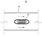
- FIG. 1 shows an example of a conventional inline heater.
- the conventional inline heater 10 is generally equipped with a coil-shaped metal heating element 12 in a pipe 11 to heat the working fluid directly.
- the coil-shaped metal heating element 12 to be inserted is directly exposed to the working fluid is vulnerable to physical damage, there was a problem of short life.
- a part of the coil-type metal heating element 12 is disconnected, it takes a long time to replace or repair it, and thus there is a problem that the yield of the entire process is lowered.
- an object of the present invention is to provide a cartridge-type inline heater capable of heating to a constant temperature regardless of the position inside the pipe, to solve such a conventional problem, to improve the oil-tightness of the pipeline. .
- the object is, according to the present invention, the body portion having a mounting portion formed along the longitudinal direction, having a swirl portion wound in a spiral along the longitudinal direction of the body portion, heat exchange for inducing the working fluid to flow along the swirl portion part; It is achieved by a cartridge type in-line heater comprising a; is inserted along the longitudinal direction of the heat exchanger to heat the working fluid in contact with the heat exchanger.
- the swirl portion may be formed in a plurality of spaced apart from each other along the circumferential direction of the body portion, and may further include an exterior portion enclosed by the swirl portion and mounted apart from the body portion.
- exterior part may be mounted to be in close contact with the swirl part such that the working fluid flowing in any one fluid flow path about the swirl part does not face the neighboring fluid flow path.
- a flow pattern may be formed on the surface of the swirl part in contact with the working fluid such that the pressure resistance between the swirl part and the working fluid is reduced.
- a system using a cartridge type inline heater comprising: a temperature control section in which a plurality of cartridge type inline heaters are arranged in series or in parallel; It is achieved by the operating fluid temperature control system comprising a; control unit for controlling each of the cartridge type in-line heater in the temperature control section.
- a cartridge type inline heater which can improve durability by inserting the cartridge type heater into the heat exchanger to heat the working fluid through indirect contact.
- It can also be used to improve the oil-by-water reliability of pipelines in offshore plants, and can also be used in processes where high- or high-temperature fluid flows are applied, such as heating unit processes in petrochemical plants and unit units inside nuclear power plant systems.
- FIG. 2 is a perspective view of a cartridge type inline heater according to a first embodiment of the present invention
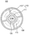
- FIG. 3 is a cross-sectional view taken along the line III-III 'of the cartridge type inline heater of FIG.
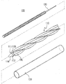
- FIG 4 is an exploded perspective view of the cartridge type inline heater of Figure 2
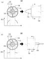
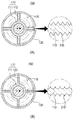
- Figure 5 (a) shows the working fluid temperature gradient of the longitudinal section of the region in which the working fluid flows in the cartridge type inline heater of Figure 2,
- Figure 5 (b) shows the working fluid temperature gradient of the longitudinal section of the region in which the working fluid flows out of the cartridge type inline heater of Figure 2,
- FIG. 6 is a cross-sectional view of the cartridge type in-line heater according to the second embodiment of the present invention.
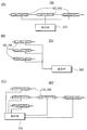
- FIG. 7 schematically illustrates a working fluid temperature control system using a cartridge type inline heater according to an embodiment of the present invention.
- Figure 2 is a perspective view of a cartridge type inline heater according to a first embodiment of the present invention
- Figure 3 is a cross-sectional view taken along the line III-III 'of the cartridge type inline heater of Figure 2
- Figure 4 2 is an exploded perspective view of the cartridge type inline heater.
- the cartridge type in-line heater 100 includes a heat exchange part 110, a heater 120, an exterior part 130, and a heat insulating member (not shown). Include.
- the heat exchange part 110 forms a fluid flow path 115 through which the working fluid flows, and is a member for transferring heat generated from the heater 120 to be described later to the working fluid.
- the body portion 111 is formed of a stainless steel material as a cylinder shape, but the shape and material are not limited to the above-described contents. On the other hand, in the center of the body portion 111 so that the heater 120 to be described later is mounted so that the mounting portion 112 penetrates along the longitudinal direction.
- the swirl portion 113 protrudes outward from the outer circumferential surface of the body portion 111, and is formed in a spiral winding form along the longitudinal direction of the outer circumferential surface of the body portion 111, and the swirl portion 113 is the body portion ( 111 may be formed by a method such as welding or diffusion bonding.
- the material of the swirl portion 113 may be the same stainless steel as the above-described body portion 111, but is not limited thereto.
- the body portion 111 is provided with a plurality of swirl portion 113, the space between any one swirl portion 113 and the neighboring swirl portion 113 forms a fluid flow path (115) . That is, the neighboring and opposite swirl portion 113 forms the side wall surface of the fluid flow path 115, and the outer circumferential surface of the body portion 111 forms the bottom surface of the fluid flow path 115, and the exterior part 130 described later. An inner circumferential surface of the upper surface of the fluid flow path 115 is formed.
- the number of swirl portions 113 may be formed as many as the number of swirl portions 113 provided with the fluid flow path 115.
- the height of the swirl portion 113 is preferably determined in consideration of the inner diameter of the exterior portion 130 to be in close contact with the inner peripheral surface of the exterior portion 130, which will be described later, the number of swirl portion 113, swirl portion 113 The thickness, the number of times of winding of the swirl portion 113 is preferably determined in consideration of specific flow conditions, such as the flow rate of the working fluid flow, temperature and pressure.
- the closing member 114 is a member for closing the end of the mounting portion 112 so that the heater 120, which will be described later, does not leave the mounting portion 112 to the outside.
- the heater 120 is composed of a cartridge-type heater of the type that generates heat by inserting a heating wire in the heating tube is formed long.
- the heater 120 is mounted in the mounting portion 112 penetrated along the longitudinal direction of the body portion 111.
- the heater 120 has a cylindrical shape so that the heat generated from the heater 120 can be transferred to the body portion 111 without loss, the body portion 111 has an inner diameter corresponding to the outer diameter of the heater 120 It is mounted in close contact with the mounting portion 112 penetrating. That is, the outer surface of the heater 120 is preferably in close contact with the inner surface of the mounting portion 112 to maximize the heat transfer area.
- the exterior part 130 is provided in a cylindrical shape, and a space is formed therein to accommodate the body part 111 and the swirl part 113 described above.
- the swirl portion 113 is formed on the outside of the body portion 111, the outer portion 130 is the outer portion 130 in the form of the inner peripheral surface in close contact with the outermost end of the swirl portion 113.
- the heat exchanger 110 are coupled to each other.
- the end portion of the swirl portion 113 is in close contact with the inner circumferential surface of the exterior portion 130, the interchange between the working fluid flowing through the fluid flow path 115 formed on both sides of the swirl portion 113 Can be prevented.
- the heat insulating member (not shown) surrounds the outer circumferential surface of the exterior portion 130 and is a member for minimizing heat loss by preventing heat exchange between the exterior portion 130 and the outside air.
- a working fluid flows into the space between the body 111 and the exterior 130, that is, the fluid flow path 115 between neighboring swirls 113, and at the same time, the heater 120 operates to generate heat. Let's do it.
- the heater generated from the heater 120 is transferred to the working fluid flowing through the body portion 111 to heat the working fluid.
- Figure 5 (a) shows the working fluid temperature gradient of the longitudinal section of the region in which the working fluid flows in the cartridge type inline heater of FIG.
- the working fluid flows in the fluid flow path 115, it is forcedly spirally moved along the direction in which the swirl portion 113 is formed under the influence of the spiral swirl portion 113, and the length of the body portion 111 is maintained.
- the working fluid is continuously stirred along the direction perpendicular to the direction.
- the working fluid in a relatively high temperature state at a position adjacent to the heater 120 is repeatedly exchanged with the working fluid in a relatively low temperature state at a position spaced outward from the heater 120 to form a mutual heat exchange, thereby fluid flow
- the working fluid flowing through the furnace 115 has a uniform temperature as a whole.
- FIG. 5 (b) shows the working fluid temperature gradient of the longitudinal section of the region in which the working fluid of the cartridge type inline heater flows out.
- the cartridge type in-line heater 200 includes a heat exchange part 110, a heater 120, an exterior part 130, and a heat insulating member (not shown). However, since the heater 120, the exterior part 130, and the heat insulating member have the same configuration as described above in the first embodiment, redundant description thereof will be omitted.
- the heat exchange part 110 forms a fluid flow path 115 through which the working fluid flows, and is a member for transferring heat generated from the heater 120 to the working fluid.
- the swirl portion 113 extends to the outside of the body portion 111 and is formed to spirally wound along the longitudinal direction of the body portion 111.
- the flow pattern 216 is formed on both sides of the swirl portion 113, that is, the side surface of the fluid flow path 115 in contact with the working fluid flows to form a flow.
- the flow pattern 216 may be a pattern of a repetitive prism recessed inward or protruding outward from the side of the swirl portion 113.
- the shape of the flow pattern 216 ' may be a U-shaped pattern repeatedly formed on the side of the swirl portion 113, but is not limited thereto.
- the working fluid temperature control system 300 using the cartridge type inline heater of the present embodiment includes a plurality of cartridge type inline heaters 100 and 200 and a controller 340.
- the cartridge type in-line heater (100, 200) is provided with a plurality, each cartridge type in-line heater (100, 200) so that the fluid flow path is interconnected.
- a series type in which the working fluid introduced into the first cartridge type inline heater (100, 200) is arranged in a line along the longitudinal direction so as to be discharged to the cartridge type inline heater (100, 200) disposed at the final end. are arranged in a structure.
- the controller 340 is a member for controlling the plurality of cartridge type inline heaters 100 and 200 arranged in a series structure.
- each cartridge type inline heater 100, 200 is arranged in a parallel structure arranged in a line along the width direction.
- each cartridge type inline heater 100, 200 may be composed of a complex structure in which a series structure and a parallel structure are combined. have.
- the controller 340 is each cartridge type inline heater 100 and 200 for each temperature of the discharged working fluid. Zone it.
- the controller 340 zones each of the cartridge type inline heaters 100 and 200, calculates the heating degree of the working fluid in each zone, and then heats the cartridge type inline heaters 100 and 200 included in each zone. By transmitting the information, the temperature of the working fluid is controlled zone by zone.
- heat exchanger 111 body portion
Landscapes
- Engineering & Computer Science (AREA)
- Physics & Mathematics (AREA)
- Thermal Sciences (AREA)
- Chemical & Material Sciences (AREA)
- Combustion & Propulsion (AREA)
- Mechanical Engineering (AREA)
- General Engineering & Computer Science (AREA)
- Resistance Heating (AREA)
- Heat-Exchange Devices With Radiators And Conduit Assemblies (AREA)
- Instantaneous Water Boilers, Portable Hot-Water Supply Apparatuses, And Control Of Portable Hot-Water Supply Apparatuses (AREA)
Abstract
본 발명은 카트리지형 인라인 히터에 관한 것으로서, 본 발명에 따른 카트리지형 인라인 히터는 길이방향을 따라 장착부가 형성되는 몸체부, 상기 몸체부의 길이방향을 따라서 나선으로 감기는 스월부를 구비하며, 유입되는 작동유체가 상기 스월부를 따라 유동하도록 유도하는 열교환부; 상기 열교환부의 길이방향을 따라 삽입되어 상기 열교환부와 접촉하는 상기 작동유체를 가열하는 히터;를 포함하는 것을 특징으로 한다. 이에 의하여, 향상된 내구력을 가지고 균일한 온도 분포를 가지도록 작동유체를 가열할 수 있는 카트리지형 인라인 히터가 제공된다.
Description
본 발명은 카트리지형 인라인 히터 및 이를 이용한 작동유체 온도 제어 시스템에 관한 것으로서, 보다 상세하게는 균일한 온도 구배를 갖도록 작동유체를 가열할 수 있는 카트리지형 인라인 히터 및 이를 이용한 작동유체 온도 제어 시스템에 관한 것이다.
일반적으로 오일 및 가스 채굴에서 유동안정성(flow assurance)이란, 자원 물질이 채굴되고, 부존지로부터 소비지까지 이송되는 파이프 라인 내 유동의 온도, 유량 및 압력 제어를 통하여 안정적이고 경제적으로 운송될 수 있도록 하는 것을 의미한다.
한편, 심해저를 포함하는 해양플랜트의 자원 이송에 있어 파이프 라인의 유동안정성에 가장 큰 영향을 미치는 요인은 주로 가스하이드레이트나 왁스과 같은 고형 물질로 인한 파이프 라인의 막힘 현상, 다상유동의 슬러깅 현상으로 인한 파이프 라인의 파손, 파이프 라인 내의 큰 압력 강하로 인한 유속의 변화, 점도 변화, 열 손실 등이 있다.
이에 따라, 파이프 라인의 유동안정성 확보를 위해서는, 가스하이드레이트나 왁스와 같은 고형 물질의 발생을 방지하기 위한 파이프 라인 내 작동유체의 온도 제어가 필요하다.
한편, 석유화학 플랜트의 가열 단위공정, 원자력 발전소 계통 내부 단위공정의 경우에는, 공정을 거쳐 유동하는 작동유체는 다양한 상변화를 동반하게 된다. 이때, 각 단위공정에서부터 다음의 단위공정으로 이송되는 중 작동유체의 온도를 제어하기 위한 목적으로 배관형 인라인 히터가 많이 이용된다.
이러한 히터는 각 단위공정을 연결하는 배관형태의 유동로에 히터를 장착하고, 히터로부터 발생하는 열을 통하여 유동하는 작동유체를 가열시키는 방식을 이용하고 있다.
도 1은 종래의 인라인 히터의 일례를 도시한 것이다.
도 1에 도시된 바와 같이, 종래의 인라인 히터(10)는 배관(11) 내에 코일형태의 금속 발열체(12)를 장착하여 작동유체를 직접적으로 가열하는 방식이 일반적이다.
그러나, 종래의 인라인 히터(10)의 경우, 삽입되는 코일형 금속 발열체(12)는 작동유체에 직접적으로 노출되어 물리적인 손상에 취약하고, 수명이 짧은 문제가 있었다. 특히, 이러한 코일형 금속발열체(12) 중 일부라도 단선되는 경우에는 이를 교체 또는 보수하는데 많은 시간이 소모되어 전체 공정의 수율이 저하되는 문제가 있었다.
또한, 금속 발열체(12)가 장착되어 있는 영역과 그렇지 않은 영역 간 제공되는 열량이 상이하고, 배관 내 가열되는 작동유체 온도 분포의 균일성이 보장되지 않는다는 문제가 있었다.
따라서, 본 발명의 목적은 이와 같은 종래의 문제점을 해결하기 위한 것으로서, 파이프 라인의 유동안정성을 향상시킬 수 있도록, 배관 내부 위치에 상관없이 일정한 온도로 가열할 수 있는 카트리지형 인라인 히터를 제공함에 있다.
또한, 카트리지형 인라인 히터를 이용하여 구역별로 작동유체 온도를 용이하게 제어할 수 있는 작동유체 온도 제어 시스템을 제공함에 있다.
상기 목적은, 본 발명에 따라, 길이방향을 따라 장착부가 형성되는 몸체부, 상기 몸체부의 길이방향을 따라서 나선으로 감기는 스월부를 구비하며, 유입되는 작동유체가 상기 스월부를 따라 유동하도록 유도하는 열교환부; 상기 열교환부의 길이방향을 따라 삽입되어 상기 열교환부와 접촉하는 상기 작동유체를 가열하는 히터;를 포함하는 것을 특징으로 하는 카트리지형 인라인 히터에 의해 달성된다.
또한, 상기 스월부는 복수개가 상기 몸체부의 둘레방향을 따라 상호 이격되게 형성되며, 또한, 상기 스월부를 둘러싸되 상기 몸체부로부터 이격되게 장착되는 외장부를 더 포함할 수 있다.
또한, 상기 스월부를 중심으로 어느 하나의 유체 유동로 내를 유동하는 작동유체가 이웃하는 유체 유동로를 향하지 못하도록 상기 외장부는 상기 스월부에 밀착되게 장착될 수 있다.
또한, 상기 스월부와 상기 작동유체 간의 압력저항이 감소되도록 작동유체와 접촉하는 스월부의 면에는 유동패턴이 형성될 수 있다.
또한, 상기 목적은, 본 발명에 따라, 카트리지형 인라인 히터를 이용하는 시스템으로서, 상기 카트리지형 인라인 히터 복수개가 직렬 또는 병렬로 정렬되는 온도제어구간; 상기 온도제어구간 내의 카트리지형 인라인 히터 각각을 제어하는 제어부;를 포함하는 것을 특징으로 하는 작동유체 온도 제어 시스템에 의해 달성된다.
본 발명의 일 실시예에 따르면, 카트리지형 히터를 열교환부 내부에 삽입하여 간접 접촉을 통하여 작동유체를 가열함으로써 내구력을 향상시킬 수 있는 카트리지형 인라인 히터가 제공된다.
또한, 열교환부의 외면에 나선형의 스월부가 가열되는 작동유체의 교반을 유도함으로써, 작동유체의 온도 균일성이 보장될 수 있다.
또한, 나선형 스월부에 유동패턴을 형성하여 압력저항과 마찰저항과 같은 유동저항을 감소시키고 작동유체의 유동성을 향상시킬 수 있다.
또한, 해양플랜트의 파이프 라인의 유동안정성을 향상시키는 데 사용될 수 있고, 석유화학 플랜트의 가열 단위 공정, 원자력 발전소 계통 내부 단위 공정과 같이 고압 또는 고온의 유체 유동이 적용되는 공정 내에서도 사용될 수 있다.
도 1은 종래의 인라인 히터의 일례를 도시한 것이고,
도 2는 본 발명의 제1실시예에 따른 카트리지형 인라인 히터의 사시도이고,
도 3은 도 2의 카트리지형 인라인 히터를 III-III' 선을 따라 절단한 단면을 도시한 것이고,
도 4는 도 2의 카트리지형 인라인 히터의 분해사시도이고,
도 5(a)는 도 2의 카트리지형 인라인 히터의 작동유체가 유입되는 영역의 종단면의 작동유체 온도 구배를 도시한 것이고,
도 5(b)는 도 2의 카트리지형 인라인 히터의 작동유체가 유출되는 영역의 종단면의 작동유체 온도 구배를 도시한 것이고,
도 6은 본 발명의 제2실시예에 따른 카트리지형 인라인 히터의 단면도이고,
도 7은 본 발명의 일실시예에 따른 카트리지형 인라인 히터를 이용하는 작동유체 온도 제어 시스템을 개략적으로 도시한 것이다.
설명에 앞서, 여러 실시예에 있어서, 동일한 구성을 가지는 구성요소에 대해서는 동일한 부호를 사용하여 대표적으로 제1실시예에서 설명하고, 그 외의 실시예에서는 제1실시예와 다른 구성에 대해서 설명하기로 한다.
이하, 첨부한 도면을 참조하여 본 발명의 제1실시예에 따른 카트리지형 인라인 히터(100)에 대하여 상세하게 설명한다.
도 2는 본 발명의 제1실시예에 따른 카트리지형 인라인 히터의 사시도이고, 도 3은 도 2의 카트리지형 인라인 히터를 III-III' 선을 따라 절단한 단면을 도시한 것이고, 도 4는 도 2의 카트리지형 인라인 히터의 분해사시도이다.
도 2 내지 도 4를 참조하면, 본 발명의 제1실시예에 따른 카트리지형 인라인 히터(100)는 열교환부(110)와 히터(120)와 외장부(130)와 단열부재(미도시)를 포함한다.
상기 열교환부(110)는 작동유체가 유동하기 위한 유체 유동로(115)를 형성하여 후술하는 히터(120)로부터 발생하는 열을 작동유체에 전달하기 위한 부재로서, 몸체부(111)와 스월부(113)를 포함한다.
상기 몸체부(111)는 실린더 형상으로서 스테인리스 스틸 재질로 형성되나, 형상 및 재질이 상술한 내용에 제한되는 것은 아니다. 한편, 후술하는 히터(120)가 장착될 수 있도록 몸체부(111)의 중심에는 길이방향을 따라 장착부(112)가 관통되게 형성된다.
상기 스월부(113)는 몸체부(111)의 외주면으로부터 외측으로 돌출되고, 몸체부(111)의 외주면의 길이방향을 따라 나선형으로 감기는 형태로 형성되며, 스월부(113)는 몸체부(111)에 용접 또는 디퓨전 본딩과 같은 방법에 의하여 형성될 수 있다. 이러한 스월부(113)의 재질으로는 상술한 몸체부(111)와 동일한 스테인리스 스틸이 이용될 수 있으나, 이에 제한되는 것은 아니다.
한편, 몸체부(111)에는 복수개의 스월부(113)가 마련되며, 어느 하나의 스월부(113)와 이에 이웃하는 스월부(113)의 사이의 공간은 유체 유동로(115)를 형성한다. 즉, 이웃하며 대향되는 스월부(113)는 유체 유동로(115)의 측벽면을 이루고, 몸체부(111)의 외주면은 유체 유동로(115)의 하면을 이루며, 후술하는 외장부(130)의 내주면은 유체 유동로(115)의 상면을 이루게 된다. 또한, 스월부(113)는 복수개가 마련되므로 상술한 유체 유동로(115) 역시 구비되는 스월부(113)의 갯수만큼 형성될 수 있다.
한편, 스월부(113)의 높이는 후술하는 외장부(130)의 내주면에 밀착되도록 외장부(130)의 내경을 고려하여 결정되는 것이 바람직하며, 스월부(113)의 갯수, 스월부(113)의 두께, 스월부(113)의 감기는 횟수 등은 유동하는 작동유체의 유량, 온도 및 압력 등의 구체적인 유동조건을 고려하여 결정되는 것이 바람직하다.
상기 마감부재(114)는 후술하는 히터(120)가 장착부(112) 내에서 외부로 이탈하지 않도록 장착부(112)의 단부를 마감하기 위한 부재이다.
상기 히터(120)는 길게 형성되는 전열튜브의 내부에 전열선이 삽입되어 열을 발생시키는 형태의 카트리지형 히터로 구성된다. 히터(120)는 몸체부(111)의 길이방향을 따라 관통되는 장착부(112) 내에 장착된다.
한편, 히터(120)로부터 발생하는 열이 손실없이 몸체부(111)에 열전달 될 수 있도록 히터(120)는 실린더형으로 구성되어 히터(120)의 외경에 대응되는 내경을 가지고 몸체부(111)를 관통하는 장착부(112) 내에 밀착되게 장착된다. 즉, 히터(120)의 외면은 장착부(112)의 내면에 완전 밀착되어 열전달 면적을 최대화하는 것이 바람직하다.
상기 외장부(130)는 실린더형으로 마련되며, 내부에 공간이 형성되어 내부에는 상술한 몸체부(111) 및 스월부(113)를 수용한다.
한편, 상술한 바와 같이 몸체부(111)의 외측으로는 스월부(113)가 형성되는데, 외장부(130)는 내주면이 스월부(113)의 최외곽 단부에 밀착하는 형태로 외장부(130)와 열교환부(110)가 상호 결합된다. 상술한 바와 같이, 스월부(113)의 단부가 외장부(130)의 내주면을 따라 밀착됨으로써, 스월부(113)의 양측에 형성되는 유체 유동로(115)를 유동하는 작동유체 간의 상호 교환이 방지될 수 있다.
상기 단열부재(미도시)는 외장부(130)의 외주면을 둘러싸는 것으로서, 외장부(130)와 외기의 열교환을 방지하여 열손실을 최소화하기 위한 부재이다.
지금부터는 상술한 카트리지형 인라인 히터(100)의 제1실시예의 작동에 대하여 설명한다.
몸체부(111)와 외장부(130) 사이의 공간, 즉, 이웃하는 스월부(113) 사이의 유체 유동로(115) 내로 작동유체가 유입되는 동시에, 히터(120)가 작동하여 열을 발생시킨다. 히터(120)로부터 발생되는 히터는 몸체부(111)를 통하여 유동하는 작동유체에 전달되어 작동유체를 가열한다.
도 5(a)는 도 2의 카트리지형 인라인 히터의 작동유체가 유입되는 영역의 종단면의 작동유체 온도 구배를 도시한 것이다.
도 5(a)에 도시된 바와 같이, 유체 유동로(115) 내로 작동유체가 유입되는 영역에서 본 실시예의 카트리지형 인라인 히터(100)의 종단면을 보면, 작동유체의 온도는 히터(120)와 인접한 몸체부(111) 측이 가장 높고, 외측으로 갈수록 감소하는 것을 알 수 있다.
다만, 작동유체가 유체 유동로(115) 내를 유동하면서, 나선형 스월부(113)의 영향을 받아 스월부(113)가 형성되는 방향을 따라 나선형으로 강제 이송되며, 몸체부(111)의 길이방향에 수직인 방향을 따라 작동유체는 지속적으로 교반된다.
즉, 히터(120)와 인접하는 위치에서 상대적으로 고온 상태의 작동유체는 히터(120)로부터 바깥쪽으로 이격된 위치에서 상대적으로 저온 상태인 작동유체와 반복적으로 교환되어 상호 열교환이 이루어짐으로써, 유체 유동로(115)를 유동하는 작동유체는 전체적으로 균일한 온도를 갖게 된다.
도 5(b)는 도 2의 카트리지형 인라인 히터의 작동유체가 유출되는 영역의 종단면의 작동유체 온도 구배를 도시한 것이다.
다시 말해, 도 5(b)에 도시된 바와 같이, 유체 유동로(115)의 작동유체가 유출되는 부분에서 본 실시예의 카트리지형 인라인 히터(100)의 종단면을 보면, 위치와 관계없이 작동유체의 온도는 거의 일정하게 유지됨을 알 수 있다.
다음으로 본 발명의 제2실시예에 따른 카트리지형 인라인 히터(200)에 대하여 설명한다.
본 발명의 제2실시예에 따른 카트리지형 인라인 히터(200)는 열교환부(110)와 히터(120)와 외장부(130)와 단열부재(미도시)를 포함한다. 다만, 히터(120)와 외장부(130)와 단열부재는 제1실시예에서 상술한 구성과 동일한 것이므로 중복 설명을 생략한다.
상기 열교환부(110)는 작동유체가 유동하기 위한 유체 유동로(115)를 형성하여 히터(120)로부터 발생하는 열을 작동유체에 전달하기 위한 부재로서, 몸체부(111)와 스월부(113)를 포함한다. 다만, 몸체부(111)는 제1실시예에서 상술한 구성과 동일하므로 중복 설명은 생략한다.
상기 스월부(113)는 몸체부(111)의 외측으로 연장되며, 몸체부(111)의 길이방향을 따라 나선형으로 감기도록 형성된다.
한편, 본 실시예에서의 스월부(113)의 양측면, 즉, 유체 유동로(115)의 측면을 형성하여 유동하는 작동유체와 접촉하는 면에는 유동패턴(216)이 형성된다. 상기 유동패턴(216)은 스월부(113)의 측면 상에서 내부로 함몰되거나 외측으로 돌출되는 반복적인 프리즘형태의 패턴일 수 있다.
다만, 유동패턴(216')의 형상은 스월부(113)의 측면에 반복적으로 형성되는 U자 형태의 패턴일 수도 있으며, 이에 제한되는 것은 아니다.
상술한 유동패턴(216, 216')에 의하면, 작동유체와 스월부(113) 면의 사이에서 발생하는 압력저항 및 마찰저항과 같은 유동저항을 감소시키고 작동유체의 유동성을 향상시킬 수 있다.
다음으로, 상술한 본 발명의 제1실시예 또는 제2실시예에 따른 카트리지형 인라인 히터를 이용한 작동유체 온도 제어 시스템(300)에 대하여 설명한다.
본 실시예의 카트리지형 인라인 히터를 이용한 작동유체 온도 제어 시스템(300)은 복수개의 카트리지형 인라인 히터(100, 200)와 제어부(340)를 포함한다.
상기 카트리지형 인라인 히터(100, 200)는 복수개가 마련되되, 각 카트리지형 인라인 히터(100, 200)는 유체 유동로가 상호 연결되도록 한다. 또한, 본 실시예에서는 최초의 카트리지형 인라인 히터(100, 200)에 유입된 작동유체가 최종단부에 배치되는 카트리지형 인라인 히터(100, 200)로 배출되도록 길이방향을 따라 일렬로 배치하는 직렬형 구조로 배치된다.
상기 제어부(340)는 직렬형 구조로 배치되는 복수개의 카트리지형 인라인 히터(100, 200)를 제어하기 위한 부재이다.
한편, 카트리지형 인라인 히터를 이용한 작동유체 온도 제어 시스템(300')의 다른 변형례에서는 각 카트리지형 인라인 히터(100, 200)가 폭방향을 따라 일렬로 배치되는 병렬형 구조로 배치된다.
카트리지형 인라인 히터를 이용한 작동유체 온도 제어 시스템(300'')의 또 다른 변형례에서는 각 카트리지형 인라인 히터(100, 200)가 직렬형 구조와 병렬형 구조가 복합되는 복합형 구조로 구성될 수 있다.
본 실시예의 카트리지형 인라인 히터를 이용한 작동유체 온도 제어 시스템의 작동에 대해 설명한다.
본 실시예에서 복수개의 카트리지형 인라인 히터(100, 200)가 복합형 구조로 배열된 것으로 가정하여 설명하면, 제어부(340)는 배출되는 작동유체의 온도 별로 각 카트리지형 인라인 히터(100, 200)를 구역화한다.
제어부(340)는 각 카트리지형 인라인 히터(100, 200)를 복수개로 구역화하고, 각 구역에서 작동유체의 가열 정도를 산출한 후에, 각 구역 내에 포함되는 카트리지형 인라인 히터(100, 200)에 온도정보를 전송함으로써, 작동유체의 온도를 구역별로 제어하게 된다.
본 발명의 권리범위는 상술한 실시예에 한정되는 것이 아니라 첨부된 특허청구범위 내에서 다양한 형태의 실시예로 구현될 수 있다. 특허청구범위에서 청구하는 본 발명의 요지를 벗어남이 없이 당해 발명이 속하는 기술 분야에서 통상의 지식을 가진 자라면 누구든지 변형 가능한 다양한 범위까지 본 발명의 청구범위 기재의 범위 내에 있는 것으로 본다.
100 : 본 발명의 제1실시예에 따른 카트리지형 인라인 히터
110 : 열교환부 111 : 몸체부
113 : 스월부 115 : 유체 유동로
120 : 히터 130 : 외장부
Claims (6)
- 길이방향을 따라 장착부가 형성되는 몸체부, 상기 몸체부의 길이방향을 따라서 나선으로 감기는 스월부를 구비하며, 유입되는 작동유체가 상기 스월부를 따라 유동하도록 유도하는 열교환부;상기 열교환부의 길이방향을 따라 삽입되어 상기 열교환부와 접촉하는 상기 작동유체를 가열하는 히터;를 포함하는 것을 특징으로 하는 카트리지형 인라인 히터.
- 제1항에 있어서,상기 스월부는 복수개가 상기 몸체부의 둘레방향을 따라 상호 이격되게 형성되며,상기 이웃하는 스월부 사이의 공간에는 작동유체가 유동하기 위한 유체 유동로가 형성되는 것을 특징으로 하는 카트리지형 인라인 히터.
- 제2항에 있어서,상기 스월부를 둘러싸되 상기 몸체부로부터 이격되게 장착되는 외장부를 더 포함하는 것을 특징으로 하는 카트리지형 인라인 히터.
- 제3항에 있어서,상기 스월부를 중심으로 어느 하나의 유체 유동로 내를 유동하는 작동유체가 이웃하는 유체 유동로를 향하지 못하도록 상기 외장부는 상기 스월부에 밀착되게 장착되는 것을 특징으로 하는 카트리지형 인라인 히터.
- 제4항에 있어서,상기 스월부와 상기 작동유체 간의 압력저항이 감소되도록 작동유체와 접촉하는 스월부의 면에는 유동패턴이 형성되는 것을 특징으로 하는 카트리지형 인라인 히터.
- 제1항 내지 제5항 중 어느 한 항의 카트리지형 인라인 히터를 이용하는 시스템으로서,상기 카트리지형 인라인 히터 복수개가 직렬 또는 병렬로 정렬되는 온도제어구간;상기 온도제어구간 내의 카트리지형 인라인 히터 각각을 제어하는 제어부;를 포함하는 것을 특징으로 하는 작동유체 온도 제어 시스템.
Priority Applications (1)
| Application Number | Priority Date | Filing Date | Title |
|---|---|---|---|
| US13/990,871 US9784471B2 (en) | 2011-11-18 | 2012-11-16 | Cartridge-type inline heater and system for controlling working fluid temperature using the same |
Applications Claiming Priority (2)
| Application Number | Priority Date | Filing Date | Title |
|---|---|---|---|
| KR1020110120553A KR101137528B1 (ko) | 2011-11-18 | 2011-11-18 | 카트리지형 인라인 히터 및 이를 이용한 작동유체 온도 제어 시스템 |
| KR10-2011-0120553 | 2011-11-18 |
Publications (1)
| Publication Number | Publication Date |
|---|---|
| WO2013073905A1 true WO2013073905A1 (ko) | 2013-05-23 |
Family
ID=46143848
Family Applications (1)
| Application Number | Title | Priority Date | Filing Date |
|---|---|---|---|
| PCT/KR2012/009761 Ceased WO2013073905A1 (ko) | 2011-11-18 | 2012-11-16 | 카트리지형 인라인 히터 및 이를 이용한 작동유체 온도 제어 시스템 |
Country Status (3)
| Country | Link |
|---|---|
| US (1) | US9784471B2 (ko) |
| KR (1) | KR101137528B1 (ko) |
| WO (1) | WO2013073905A1 (ko) |
Families Citing this family (4)
| Publication number | Priority date | Publication date | Assignee | Title |
|---|---|---|---|---|
| KR101358235B1 (ko) | 2013-04-11 | 2014-02-06 | 한국기계연구원 | 가스하이드레이트 발생 억제용 인라인 히팅 배관 시스템 |
| KR101510215B1 (ko) | 2013-04-12 | 2015-04-08 | 한국기계연구원 | 열혼합 인라인 히터 |
| EP3183525A4 (en) * | 2014-08-20 | 2018-04-25 | Nestec S.A. | Continuous-flow water heating assembly and production method |
| FR3073609B1 (fr) * | 2017-04-28 | 2019-10-25 | Valeo Systemes Thermiques | Canal pour echangeur thermique d'un vehicule automobile |
Citations (4)
| Publication number | Priority date | Publication date | Assignee | Title |
|---|---|---|---|---|
| JP2000259259A (ja) * | 1999-03-12 | 2000-09-22 | Sanyo Electric Co Ltd | 加熱器具のヒータ切替装置 |
| KR20050118634A (ko) * | 2004-06-14 | 2005-12-19 | 주식회사 승광 | 나선형 순간 가열용 히팅 시스템 |
| KR20060049326A (ko) * | 2004-10-26 | 2006-05-18 | 니폰 필라고교 가부시키가이샤 | 유체용히터 및 유체가열장치 |
| KR20080078637A (ko) * | 2005-10-06 | 2008-08-27 | 세브 에스.아. | 가전 기기를 위한 액체가열 장치 |
Family Cites Families (15)
| Publication number | Priority date | Publication date | Assignee | Title |
|---|---|---|---|---|
| US1382156A (en) * | 1919-05-12 | 1921-06-21 | Luis G Abogado | Apparatus for heating liquids |
| US1689521A (en) * | 1927-08-15 | 1928-10-30 | Manuel D Dominguez | Water heater |
| US2775683A (en) * | 1954-07-16 | 1956-12-25 | Dole Refrigerating Co | Heat exchangers for vaporizing liquid refrigerant |
| ES1000291Y (es) * | 1986-07-31 | 1991-01-01 | Perfils Tecnics, S.A. (Pertecsa) | Dispositivo turbulador para intercambiadores de calor, perfeccionado |
| KR900004149A (ko) | 1988-08-31 | 1990-03-27 | 강진구 | 디지폰의 키기능 변경방법 |
| DE19613411C1 (de) * | 1996-04-03 | 1997-08-21 | Steag Micro Tech Gmbh | Fluid-Heizeinrichtung mit einem von einem Fluid durchströmten Rohr |
| KR20020049086A (ko) | 2000-12-19 | 2002-06-26 | 유인종 | 반도체 공정 설비용 인라인 진공히터 |
| US20030116306A1 (en) * | 2001-12-26 | 2003-06-26 | Besik Ferdinand K. | Rotating film shell and tube type heat exchanger - evaporator |
| JP2006207936A (ja) * | 2005-01-28 | 2006-08-10 | Matsushita Electric Ind Co Ltd | 熱交換器 |
| KR101172392B1 (ko) | 2005-11-18 | 2012-08-08 | 삼성전자주식회사 | 히터 카트리지 |
| US7932480B2 (en) * | 2006-04-05 | 2011-04-26 | Mks Instruments, Inc. | Multiple heater control system with expandable modular functionality |
| KR101212575B1 (ko) | 2006-09-11 | 2012-12-14 | 씨앤지하이테크 주식회사 | 반도체 제조를 위한 유체가열용 인라인히터유닛 |
| KR20080057742A (ko) | 2006-12-20 | 2008-06-25 | 주식회사 대우일렉트로닉스 | 전자레인지의 그릴히터 구동회로 |
| TWM381776U (en) * | 2009-10-28 | 2010-06-01 | Asia Vital Components Co Ltd | Improved structure of heat exchanger |
| KR200461240Y1 (ko) | 2010-04-09 | 2012-06-28 | 허남욱 | 사출금형의 온도제어용 카트리지 히터 |
-
2011
- 2011-11-18 KR KR1020110120553A patent/KR101137528B1/ko not_active Expired - Fee Related
-
2012
- 2012-11-16 WO PCT/KR2012/009761 patent/WO2013073905A1/ko not_active Ceased
- 2012-11-16 US US13/990,871 patent/US9784471B2/en not_active Expired - Fee Related
Patent Citations (4)
| Publication number | Priority date | Publication date | Assignee | Title |
|---|---|---|---|---|
| JP2000259259A (ja) * | 1999-03-12 | 2000-09-22 | Sanyo Electric Co Ltd | 加熱器具のヒータ切替装置 |
| KR20050118634A (ko) * | 2004-06-14 | 2005-12-19 | 주식회사 승광 | 나선형 순간 가열용 히팅 시스템 |
| KR20060049326A (ko) * | 2004-10-26 | 2006-05-18 | 니폰 필라고교 가부시키가이샤 | 유체용히터 및 유체가열장치 |
| KR20080078637A (ko) * | 2005-10-06 | 2008-08-27 | 세브 에스.아. | 가전 기기를 위한 액체가열 장치 |
Also Published As
| Publication number | Publication date |
|---|---|
| KR101137528B1 (ko) | 2012-04-20 |
| US20140287374A1 (en) | 2014-09-25 |
| US9784471B2 (en) | 2017-10-10 |
Similar Documents
| Publication | Publication Date | Title |
|---|---|---|
| WO2013073905A1 (ko) | 카트리지형 인라인 히터 및 이를 이용한 작동유체 온도 제어 시스템 | |
| WO2013165106A1 (ko) | 난방효율을 향상시킨 난방 및 온수의 동시 사용이 가능한 보일러 | |
| WO2012036334A1 (ko) | 유도코일과 용융로 일체형 유도가열식 저온용융로 | |
| WO2014142561A1 (ko) | 순간 온수기 | |
| KR19990088304A (ko) | 열교환코일조립체 | |
| CZ283100B6 (cs) | Výměník tepla | |
| WO2018230817A1 (ko) | 순간 저탕식 구조를 갖는 전기 온수기 | |
| CN203090909U (zh) | 油浴加热及降温系统 | |
| CN205784731U (zh) | 一种用于尿素热解的扭曲椭圆管空气换热器系统 | |
| US5394837A (en) | High-efficiency furnace | |
| WO2020145454A1 (ko) | 순간 가열 기능을 갖는 저장식 온수기 | |
| WO2014065478A1 (ko) | 물집 열교환기 | |
| US3930537A (en) | Heat exchanger | |
| EP0028503A2 (en) | Method and apparatus for heating a fluid employing a gas containing sulfur oxides and water | |
| US4230307A (en) | Cooling apparatus for copper converter opening | |
| KR101510215B1 (ko) | 열혼합 인라인 히터 | |
| WO2025188155A1 (ko) | 전기 가열 반응기 | |
| US10330340B2 (en) | Alternative coil for fired process heater | |
| WO2016117862A1 (ko) | 온수 보일러 | |
| CN205807837U (zh) | 紧耦合电磁导热油加热炉 | |
| KR20150119114A (ko) | 열 회수부를 갖는 퍼니스 내에서의 연소 방법 | |
| LU500686B1 (en) | Electric stove | |
| KR20210079804A (ko) | 균일한 유체를 공급하는 배관 장치 | |
| JP2000106269A (ja) | 半導体製造装置用反応ガスの加熱用熱交換器 | |
| KR20210087183A (ko) | 물 이송을 위한 단일 배관용 3상 4선 전기히터 |
Legal Events
| Date | Code | Title | Description |
|---|---|---|---|
| WWE | Wipo information: entry into national phase |
Ref document number: 13990871 Country of ref document: US |
|
| 121 | Ep: the epo has been informed by wipo that ep was designated in this application |
Ref document number: 12849799 Country of ref document: EP Kind code of ref document: A1 |
|
| NENP | Non-entry into the national phase |
Ref country code: DE |
|
| 122 | Ep: pct application non-entry in european phase |
Ref document number: 12849799 Country of ref document: EP Kind code of ref document: A1 |