WO2013069538A1 - Wireless communication system, wireless base station, user equipment, and wireless communication method - Google Patents
Wireless communication system, wireless base station, user equipment, and wireless communication method Download PDFInfo
- Publication number
- WO2013069538A1 WO2013069538A1 PCT/JP2012/078341 JP2012078341W WO2013069538A1 WO 2013069538 A1 WO2013069538 A1 WO 2013069538A1 JP 2012078341 W JP2012078341 W JP 2012078341W WO 2013069538 A1 WO2013069538 A1 WO 2013069538A1
- Authority
- WO
- WIPO (PCT)
- Prior art keywords
- base station
- sequence
- pseudo
- reference signal
- user terminal
- Prior art date
Links
Images


Classifications
-
- H—ELECTRICITY
- H04—ELECTRIC COMMUNICATION TECHNIQUE
- H04B—TRANSMISSION
- H04B7/00—Radio transmission systems, i.e. using radiation field
- H04B7/02—Diversity systems; Multi-antenna system, i.e. transmission or reception using multiple antennas
- H04B7/022—Site diversity; Macro-diversity
- H04B7/024—Co-operative use of antennas of several sites, e.g. in co-ordinated multipoint or co-operative multiple-input multiple-output [MIMO] systems
-
- H—ELECTRICITY
- H04—ELECTRIC COMMUNICATION TECHNIQUE
- H04L—TRANSMISSION OF DIGITAL INFORMATION, e.g. TELEGRAPHIC COMMUNICATION
- H04L5/00—Arrangements affording multiple use of the transmission path
- H04L5/003—Arrangements for allocating sub-channels of the transmission path
- H04L5/0048—Allocation of pilot signals, i.e. of signals known to the receiver
- H04L5/0051—Allocation of pilot signals, i.e. of signals known to the receiver of dedicated pilots, i.e. pilots destined for a single user or terminal
-
- H—ELECTRICITY
- H04—ELECTRIC COMMUNICATION TECHNIQUE
- H04L—TRANSMISSION OF DIGITAL INFORMATION, e.g. TELEGRAPHIC COMMUNICATION
- H04L25/00—Baseband systems
- H04L25/02—Details ; arrangements for supplying electrical power along data transmission lines
- H04L25/0202—Channel estimation
-
- H—ELECTRICITY
- H04—ELECTRIC COMMUNICATION TECHNIQUE
- H04L—TRANSMISSION OF DIGITAL INFORMATION, e.g. TELEGRAPHIC COMMUNICATION
- H04L25/00—Baseband systems
- H04L25/02—Details ; arrangements for supplying electrical power along data transmission lines
- H04L25/0202—Channel estimation
- H04L25/0224—Channel estimation using sounding signals
- H04L25/0226—Channel estimation using sounding signals sounding signals per se
-
- H—ELECTRICITY
- H04—ELECTRIC COMMUNICATION TECHNIQUE
- H04W—WIRELESS COMMUNICATION NETWORKS
- H04W76/00—Connection management
- H04W76/10—Connection setup
- H04W76/15—Setup of multiple wireless link connections
Definitions
- the present invention relates to a radio communication system, a radio base station apparatus, a user terminal, and a radio communication method applicable to a cellular system or the like.
- Non-patent Document 1 In the UMTS (Universal Mobile Telecommunications System) network, WSDPA (High Speed Downlink Packet Access) and HSUPA (High Speed Uplink Packet Access) are adopted for the purpose of improving frequency utilization efficiency and data rate.
- the system features based on CDMA (Wideband-Code Division Multiple Access) are being extracted to the maximum.
- LTE Long Term Evolution
- Non-patent Document 1 LTE (Long Term Evolution) has been studied for the purpose of further high data rate and low delay.
- the third generation system can achieve a maximum transmission rate of about 2 Mbps on the downlink using generally a fixed bandwidth of 5 MHz.
- a maximum transmission rate of about 300 Mbps on the downlink and about 75 Mbps on the uplink can be realized using a variable band of 1.4 MHz to 20 MHz.
- LTE-A LTE Advanced
- inter-cell orthogonalization is one promising technique for further improving the system performance over the LTE system.
- orthogonalization within a cell is realized by orthogonal multi-access for both uplink and downlink. That is, in the downlink, orthogonalization is performed between user terminals UE (User Equipment) in the frequency domain.
- UE User Equipment
- W-CDMA Wideband Code Division Multiple Access
- a coordinated multi-point transmission / reception (CoMP) technique is being studied as a technique for realizing inter-cell orthogonalization.
- CoMP coordinated multi-point transmission / reception
- a plurality of cells perform transmission / reception signal processing in cooperation with one or a plurality of user terminals UE.
- simultaneous transmission of multiple cells to which precoding is applied, cooperative scheduling / beamforming, and the like are being studied.
- Application of these CoMP transmission / reception techniques is expected to improve the throughput characteristics of the user terminal UE located particularly at the cell edge.
- a configuration including a plurality of remote radio devices RRE: Remote Radio Equipment
- RRE Remote Radio Equipment
- radio base station device eNB radio base station device
- RRE optical fiber
- the remote radio apparatus RRE is centrally controlled by the radio base station apparatus eNB.
- an optical fiber is used between a radio base station apparatus eNB (concentrated base station) that performs baseband signal processing and control of a plurality of remote radio apparatuses RRE and each cell (that is, each remote radio apparatus RRE). Since connection is performed using a baseband signal, radio resource control between cells can be performed collectively in a centralized base station. Therefore, in the RRE configuration, a method using high-speed signal processing between cells such as simultaneous transmission of a plurality of cells can be applied in the downlink.
- the transmission power of the remote radio apparatus RRE is approximately the same as the transmission power of the radio base station apparatus (macro base station) eNB (high transmission power RRE).
- an overlay type network environment in which a plurality of remote radio apparatuses RRE are arranged in a cover area of a radio base station apparatus (macro base station) eNB. Environment).
- the cell of the macro base station eNB and the cell of the remote radio apparatus RRE are different, that is, the cell identification information (cell ID) of the macro base station eNB and the cell ID of the remote radio apparatus RRE are different (first 1 heterogeneous environment) and the cell of the macro base station eNB and the cell of the remote radio apparatus RRE are the same, that is, the environment where the cell ID of the macro base station eNB and the cell ID of the remote radio apparatus RRE are the same (second Heterogeneous environment).
- the transmission power of the remote radio apparatus RRE is lower than the transmission power of the radio base station apparatus (macro base station) eNB (low transmission power RRE).
- the control environment is simpler than the first heterogeneous environment.
- the cell of the macro base station eNB the hexagonal cell in FIG. 2
- the cell of the remote radio apparatus RRE the circular cell in FIG. 2. It is difficult to determine which cell the downlink signal is from, which causes a problem that reception accuracy is lowered. For example, if the user terminal cannot determine from which cell a reference signal sequence such as a demodulation reference signal or a channel state information reference signal is transmitted, the demodulation accuracy and the channel estimation accuracy are reduced. There's a problem.
- An object of the present invention is to provide a radio communication system, a radio base station apparatus, a user terminal, and a radio communication method.
- a radio communication system of the present invention is a radio communication system comprising a plurality of radio base station devices and a user terminal configured to be capable of cooperative multipoint transmission / reception with the plurality of radio base station devices, wherein the radio base station
- the station apparatus includes a generation unit that generates a reference signal sequence using a pseudo-random sequence using user-specific information, and a transmission unit that transmits the reference signal sequence to a user terminal. It has a signal processing part which performs signal processing using the reference signal sequence transmitted from the radio base station apparatus.
- a radio base station apparatus is a radio base station apparatus in a radio communication system comprising a plurality of radio base station apparatuses and a user terminal configured to be capable of cooperative multipoint transmission / reception with the plurality of radio base station apparatuses.
- a generation unit that generates a reference signal sequence using a pseudo-random sequence using user-specific information, and a transmission unit that transmits the reference signal sequence to a user terminal.
- a user terminal is a user terminal in a radio communication system comprising a plurality of radio base station devices and a user terminal configured to be capable of cooperative multipoint transmission / reception with the plurality of radio base station devices,
- a signal processing unit is provided that performs signal processing using a reference signal sequence that is transmitted from a radio base station apparatus and is generated using a pseudo-random sequence using user-specific information.
- a radio communication method of the present invention is a radio communication method of a radio communication system comprising a plurality of radio base station devices and a user terminal configured to be capable of cooperative multipoint transmission / reception with the plurality of radio base station devices.
- a step of generating a reference signal sequence using a pseudo random sequence using user-specific information a step of transmitting the reference signal sequence to a user terminal, and in the user terminal, the radio base station And a step of performing signal processing using the reference signal sequence transmitted from the station apparatus.
- the present invention even in a heterogeneous environment using the same cell identification information, it is possible to determine from which cell the user terminal is a downlink signal, thereby maintaining reception accuracy.
- Downlink CoMP transmission includes Coordinated Scheduling / Coordinated Beamforming and Joint processing.
- Coordinated Scheduling / Coordinated Beamforming is a method for transmitting a shared data channel from only one cell to one user terminal UE, and in the frequency / space domain considering interference from other cells and interference to other cells. Assign radio resources.
- Joint processing is a method for transmitting a shared data channel from a plurality of cells at the same time by applying precoding, and a joint transmission for transmitting a shared data channel from a plurality of cells to one user terminal UE, and an instantaneous process.
- DPS Dynamic Point Selection
- the cell ID of the macro base station eNB and the cell ID of the remote radio apparatus RRE are the same.
- a reference signal sequence for example, a demodulation reference signal sequence (DM-RS sequence) or a channel state information reference signal sequence (CSI-RS sequence)
- CSI-RS sequence channel state information reference signal sequence
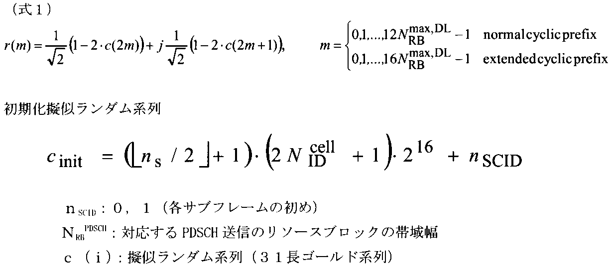
- the DM-RS sequence r (m) is defined by the following formula (1) (Release 10 LTE).
- the pseudo-random sequence c (i) included in the equation (1) is initialized as follows (C init ).
- the initialization As can be seen from the pseudo-random sequence C init, contains different terms N ID cell by cell ID in the initialized pseudo random sequence C init. Note that this pseudo-random sequence c (i) is generated using a 31-length gold sequence. Also, during initialization pseudo random sequence C init, it includes scrambling identity (SCID) is. This SCID takes values of 0 and 1 (the beginning of each subframe). Thus, the pseudo-random sequence used when generating the DM-RS sequence r (m) is set so as to differ depending on the cell ID.
- SCID scrambling identity
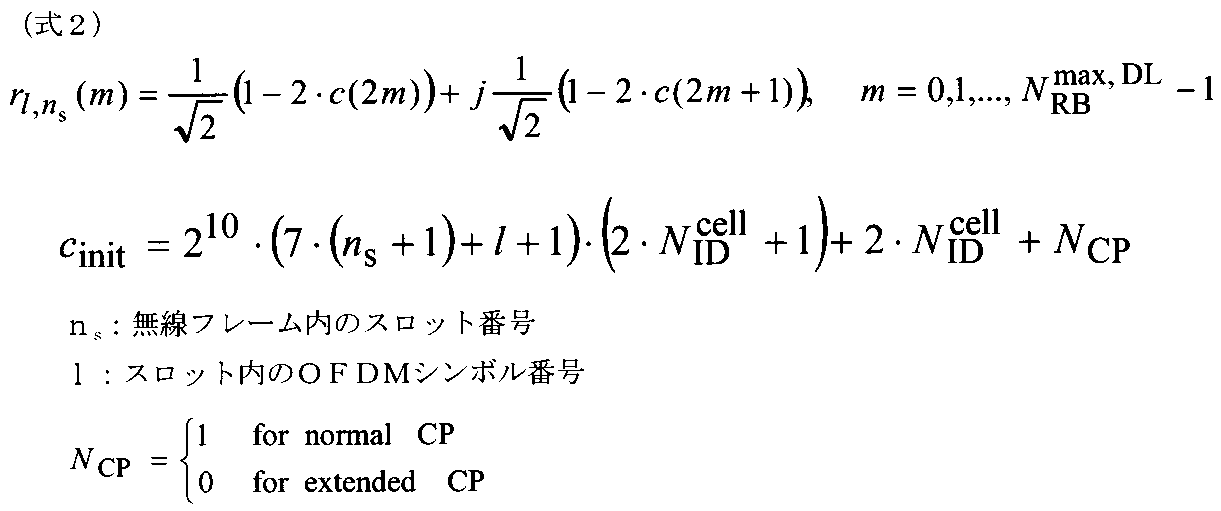
- the CSI-RS sequence r l, ns (m) is defined by the following equation (2) (Release 10 LTE).
- the pseudo-random sequence c (i) included in the equation (2) is initialized as follows (C init ).
- the initialization As can be seen from the pseudo-random sequence C init, contains different terms N ID cell by cell ID in the initialized pseudo random sequence C init.
- the pseudo-random sequence used when generating the CSI-RS sequence r l, ns (m) is also set to be different depending on the cell ID.
- both the DM-RS sequence and the CSI-RS sequence are generated using a pseudo-random sequence including different terms depending on the cell ID, in the second heterogeneous environment, the cell of the macro base station eNB Since the ID and the cell ID of the remote radio device RRE are the same, the same DM-RS sequence and CSI-RS sequence are applied between the macro base station eNB and the plurality of remote radio devices RRE. There is a high possibility that DM-RS and CSI-RS are multiplexed in resources. In such a state, it becomes difficult to determine whether the user terminal is a downlink signal from the macro base station eNB or a downlink signal from the remote radio apparatus RRE (reference signal collision) (FIG. 3).
- a DM-RS collision may cause a decrease in DM-RS channel estimation accuracy and a PDSCH demodulation accuracy
- a CSI-RS collision may cause a decrease in CSI-RS channel estimation accuracy and CSI estimation accuracy.
- the present inventor has a high possibility that a reference signal collision occurs in the second heterogeneous environment because the pseudo-random sequence used when generating the reference signal sequence includes a term different depending on the cell ID. It is possible to avoid collision of reference signals in the second heterogeneous environment by using user specific information, for example, user identification information (UEID), as a pseudo-random sequence used when generating a reference signal sequence.
- UEID user identification information
- the gist of the present invention is that a radio base station apparatus generates a reference signal sequence using a pseudo-random sequence using user-specific information, transmits the reference signal sequence to the user terminal, and the user terminal By performing signal processing using the reference signal sequence transmitted from the device, even in a heterogeneous environment using the same cell identification information, the user terminal determines which cell the downlink signal is from, and receives it accordingly It is to maintain accuracy.
- user-specific information such as user identification information (UEID) is used for the pseudo-random sequence used when generating the reference signal sequence.
- the DM-RS sequence is generated using user identification information (UEID) instead of the cell ID in the pseudo-random sequence as shown in the following formula (3) (first method). That is, the term N ID cell in the equation (1) in the initialized pseudo-random sequence is changed to the term UE ID .
- the cell ID of the cell of the macro base station eNB and the remote radio overlaid with this cell Since the cell ID of the cell of the device RRE is the same, the same DM-RS sequence is used in the user terminals UE # 1 to # 3, and there is a high possibility that the multiplexing positions of the DM-RS are the same. -An RS collision occurs, and it becomes difficult for the user terminal UE to determine whether it is a downlink signal from the macro base station eNB or a downlink signal from the remote radio apparatus RRE.
- the cell ID of the cell of the macro base station eNB is overlaid with the cell in the second heterogeneous environment shown in FIG.
- the cell IDs of the cells of the remote radio apparatus RRE are the same, but since the UE IDs are different in the user terminals UE # 1 to # 3, different DM-RS sequences are used in the user terminals UE # 1 to # 3. -It is less likely that the multiple positions of the RS will be the same.
- the pseudo-random sequence using Equation (3) is a pseudo-random sequence using user specific information.
- the DM-RS sequence is generated using the user specific information X1 instead of the cell ID in the pseudo-random sequence as shown in the following equation (4) (second method 1). That is, the term N ID cell in the equation (1) in the initialized pseudo-random sequence is changed to the term X1.
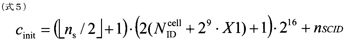
- the DM-RS sequence is generated by adding user-specific information X1 to the cell ID in the pseudo-random sequence as shown in the following formula (5) (second method 2-2). That is, the term X1 is added to the term N ID cell of the equation (1) in the initialized pseudo-random sequence.
- the term X1 in the initialization pseudo-random sequence is a term using user-specific information.
- X1 is notified to the user terminal by higher layer or signaling (for example, RRC signaling).
- X1 is a value unique to the user, and the same X1 is signaled to a specific group of user terminals. Thereby, it can be set as the pseudorandom series using user specific information, without being tied to UEID.
- the cell ID of the cell of the macro base station eNB and the remote radio overlaid with this cell Since the cell ID of the cell of the device RRE is the same, the same DM-RS sequence is used in the user terminals UE # 1 to # 3, and there is a high possibility that the multiplexing positions of the DM-RS are the same. -An RS collision occurs, and it becomes difficult for the user terminal UE to determine whether it is a downlink signal from the macro base station eNB or a downlink signal from the remote radio apparatus RRE.
- the DM-RS sequence is generated using the pseudo-random sequence shown in the above equations (4) and (5), in the second heterogeneous environment shown in FIG. 3, the cell ID of the cell of the macro base station eNB, This cell and the cell ID of the cell of the overlaid remote radio apparatus RRE are the same, but by generating a different pseudo-random sequence using higher layer signaling notified from the radio base station apparatus, the user terminal UE # 1 Different DM-RS sequences are used in ⁇ # 3, and the possibility that the multiplexing positions of DM-RS are the same is reduced.
- the user terminal UE can easily determine whether it is a downlink signal from the macro base station eNB or a downlink signal from the remote radio apparatus RRE. As a result, DM-RS channel estimation accuracy and PDSCH demodulation accuracy can be maintained.
- the DM-RS sequence is generated using the UEID instead of the SCID in the pseudo-random sequence as shown in the following formula (6) (third method). That is, the term n SCID of the equation (1) in the initialized pseudo-random sequence is changed to the term X2 (X2 is a term using user specific information (UE ID )).
- the term X2 in the initialization pseudo-random sequence is a term using user specific information (UE ID ).
- UE ID user specific information
- n SCID is dynamically transmitted from the radio base station apparatus to the user terminal using a downlink control channel signal.
- DCI downlink control information
- the term X2 is dynamically transmitted using downlink control information (DCI).
- DCI downlink control information
- the value “0” or “1” of X2 can be defined as follows. By defining as follows, the form of notification using DCI is not changed. Moreover, backward compatibility can be achieved by such a definition.
- a pseudo-random sequence using the term X2 defined as follows is set as a pseudo-random sequence using user-specific information.
- X2 0: Value “0” and UEID is not used
- X2 1: UEID (UE number)
- the cell ID of the cell of the macro base station eNB and the remote radio overlaid with this cell Since the cell ID of the cell of the device RRE is the same, the same DM-RS sequence is used in the user terminals UE # 1 to # 3, and there is a high possibility that the multiplexing positions of the DM-RS are the same. -An RS collision occurs, and it becomes difficult for the user terminal UE to determine whether it is a downlink signal from the macro base station eNB or a downlink signal from the remote radio apparatus RRE.
- the cell ID of the cell of the macro base station eNB is overlaid with this cell.
- the cell IDs of the cells of the remote radio apparatus RRE are the same, but since the UE IDs are different in the user terminals UE # 1 to # 3, different DM-RS sequences are used in the user terminals UE # 1 to # 3. -It is less likely that the multiple positions of the RS will be the same.
- the user terminal UE can easily determine whether it is a downlink signal from the macro base station eNB or a downlink signal from the remote radio apparatus RRE. As a result, DM-RS channel estimation accuracy and PDSCH demodulation accuracy can be maintained.
- the DM-RS sequence is generated by adding the term Y1 as shown in the following formula (7) (fourth method). That is, the term Y1 is added to Equation (1) in the initialized pseudo-random sequence.
- the term Y1 in the initialization pseudo-random sequence is user-specific.
- the information of this term Y1 is notified from the radio base station apparatus to the user terminal by higher layer signaling (for example, RRC signaling).
- the pseudo-random sequence using the above equation (7) is a pseudo-random sequence (a pseudo-random sequence for realizing UE-specific operation) in which the radio base station apparatus uses user-specific information. is there.
- the cell ID of the cell of the macro base station eNB and the remote radio overlaid with this cell Since the cell ID of the cell of the device RRE is the same, the same DM-RS sequence is used in the user terminals UE # 1 to # 3, and there is a high possibility that the multiplexing positions of the DM-RS are the same. -An RS collision occurs, and it becomes difficult for the user terminal UE to determine whether it is a downlink signal from the macro base station eNB or a downlink signal from the remote radio apparatus RRE.
- the cell ID of the cell of the macro base station eNB is overlaid with this cell.
- the cell IDs of the cells of the remote radio apparatus RRE are the same, but differ by the user terminals UE # 1 to # 3 by generating different pseudo-random sequences using higher layer signaling notified from the radio base station apparatus
- the DM-RS sequence is used, and the possibility that the multiplexing positions of the DM-RS are the same is reduced.
- the user terminal UE can easily determine whether it is a downlink signal from the macro base station eNB or a downlink signal from the remote radio apparatus RRE. As a result, DM-RS channel estimation accuracy and PDSCH demodulation accuracy can be maintained.
- a CSI-RS sequence is generated by adding a UEID in a pseudo-random sequence as shown in the following equation (8) (fifth method). That is, the UE ID is added to Equation (2) in the initialization pseudo-random sequence.
- the cell ID of the cell of the macro base station eNB and the remote radio overlaid with this cell Since the cell ID of the cell of the device RRE is the same, the same CSI-RS sequence is used in the user terminals UE # 1 to # 3, and there is a high possibility that the CSI-RS multiplexing positions are the same. -An RS collision occurs, and it becomes difficult for the user terminal UE to determine whether it is a downlink signal from the macro base station eNB or a downlink signal from the remote radio apparatus RRE.
- the CSI-RS channel estimation accuracy and the CSI-RS accuracy may be degraded.
- the cell ID of the cell of the macro base station eNB is overlaid with this cell in the second heterogeneous environment shown in FIG.
- the cell IDs of the cells of the remote radio apparatus RRE are the same, but since the UE IDs are different in the user terminals UE # 1 to # 3, different CSI-RS sequences are used in the user terminals UE # 1 to # 3, and the CSI -It is less likely that the multiple positions of the RS will be the same.
- the pseudo-random sequence using the above equation (8) is set as a pseudo-random sequence using user specific information (UE ID ).
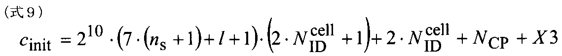
- the CSI-RS sequence is generated by adding the term X3 in the pseudo-random sequence as shown in the following formula (9) (sixth method). That is, the term X3 is added to Equation (2) in the initialized pseudo-random sequence.
- the term X3 in the initialization pseudo-random sequence is a term using user specific information (UE ID ).
- the term X3 is a term for distinguishing between the case where the initialization pseudo-random sequence is user-specific and the case where the initialization pseudo-random sequence is not user-specific. For example, if it is user-specific, the term X3 is set as the UE ID (in this case, the fifth method), and if not specific to the user, the term X3 is set to 0. That is, it is determined whether or not to be user-specific in the radio base station apparatus, and the initialization pseudo-random sequence is changed based on the determination (determines whether or not to add a user-specific term (X3)).
- the pseudo-random sequence using (9) is a pseudo-random sequence using user specific information.
- the cell ID of the cell of the macro base station eNB and the remote radio overlaid with this cell Since the cell ID of the cell of the device RRE is the same, the same CSI-RS sequence is used in the user terminals UE # 1 to # 3, and there is a high possibility that the CSI-RS multiplexing positions are the same. -An RS collision occurs, and it becomes difficult for the user terminal UE to determine whether it is a downlink signal from the macro base station eNB or a downlink signal from the remote radio apparatus RRE.
- the CSI-RS channel estimation accuracy and the CSI-RS accuracy may be degraded.
- the cell ID of the cell of the macro base station eNB is overlaid with this cell in the second heterogeneous environment shown in FIG.
- the cell IDs of the cells of the remote radio apparatus RRE are the same, but since the UE IDs are different in the user terminals UE # 1 to # 3, different CSI-RS sequences are used in the user terminals UE # 1 to # 3, and the CSI -It is less likely that the multiple positions of the RS will be the same.
- CSI-RS collision does not occur, and the user terminal UE can easily determine whether it is a downlink signal from the macro base station eNB or a downlink signal from the remote radio apparatus RRE. As a result, CSI-RS channel estimation accuracy and CSI-RS accuracy can be maintained.
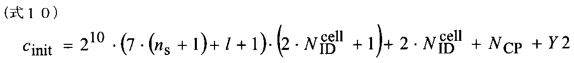
- the CSI-RS sequence is generated by adding the term Y2 in the pseudo-random sequence as shown in the following formula (10) (seventh method). That is, the term Y2 is added to Equation (2) in the initialized pseudo-random sequence.
- the term Y2 in the initialization pseudo-random sequence is user-specific.
- the information of this term Y2 is notified from the radio base station apparatus to the user terminal by higher layer signaling (for example, RRC signaling).
- the pseudo-random sequence using the above equation (10) is a pseudo-random sequence (a pseudo-random sequence for realizing UE-specific operation) in which the radio base station apparatus uses user-specific information. is there.
- the cell ID of the cell of the macro base station eNB and the remote radio overlaid with this cell Since the cell ID of the cell of the device RRE is the same, the same CSI-RS sequence is used in the user terminals UE # 1 to # 3, and there is a high possibility that the CSI-RS multiplexing positions are the same. -An RS collision occurs, and it becomes difficult for the user terminal UE to determine whether it is a downlink signal from the macro base station eNB or a downlink signal from the remote radio apparatus RRE.
- the CSI-RS channel estimation accuracy and the CSI-RS accuracy may be degraded.
- the cell ID of the cell of the macro base station eNB is overlaid with this cell in the second heterogeneous environment shown in FIG.
- the cell IDs of the cells of the remote radio apparatus RRE are the same, but differ by the user terminals UE # 1 to # 3 by generating different pseudo-random sequences using higher layer signaling notified from the radio base station apparatus A CSI-RS sequence is used, and the possibility that CSI-RS multiplexing positions are the same is reduced.
- CSI-RS collision does not occur, and the user terminal UE can easily determine whether it is a downlink signal from the macro base station eNB or a downlink signal from the remote radio apparatus RRE. As a result, CSI-RS channel estimation accuracy and CSI-RS accuracy can be maintained.
- FIG. 4 is an explanatory diagram of the system configuration of the wireless communication system according to the present embodiment.
- This radio communication system includes a plurality of radio base station apparatuses and user terminals configured to be capable of cooperative multipoint transmission / reception with the plurality of radio base station apparatuses.
- the radio communication system shown in FIG. 4 is a system including, for example, an LTE system or SUPER 3G.
- carrier aggregation in which a plurality of fundamental frequency blocks with the system band of the LTE system as a unit is integrated is used.
- this wireless communication system may be called IMT-Advanced or 4G.
- the radio communication system 1 includes radio base station apparatuses 20A and 20B and a plurality of first and second user terminals 10A and 10B communicating with the radio base station apparatuses 20A and 20B. It is configured.
- the radio base station devices 20 ⁇ / b> A and 20 ⁇ / b> B are connected to the higher station device 30, and the higher station device 30 is connected to the core network 40.
- the radio base station apparatuses 20A and 20B are connected to each other by wired connection or wireless connection.
- the first and second user terminals 10A and 10B can communicate with the radio base station apparatuses 20A and 20B in the cells C1 and C2.
- the upper station device 30 includes, for example, an access gateway device, a radio network controller (RNC), a mobility management entity (MME), and the like, but is not limited thereto. Note that, between cells, control of CoMP transmission is performed by a plurality of base stations as necessary.
- RNC radio network controller
- MME mobility management entity
- the first and second user terminals 10A and 10B include an LTE terminal and an LTE-A terminal. In the following, the description will proceed as the first and second user terminals unless otherwise specified. Further, for convenience of explanation, it is assumed that the first and second user terminals 10A and 10B communicate wirelessly with the radio base station apparatuses 20A and 20B, but more generally both user terminals and fixed terminal apparatuses are used.
- the user equipment (UE) may be included.
- OFDMA Orthogonal Frequency Division Multiple Access
- SC-FDMA Single Carrier-Frequency Division Multiple Access
- the wireless access method is not limited to this.
- OFDMA is a multi-carrier transmission scheme that performs communication by dividing a frequency band into a plurality of narrow frequency bands (subcarriers) and mapping data to each subcarrier.
- SC-FDMA is a single carrier transmission method that reduces interference between terminals by dividing a system band into bands each consisting of one or continuous resource blocks for each terminal, and a plurality of terminals using different bands. .
- the downlink communication channel includes PDSCH (Physical Downlink Shared Channel) as a downlink data channel shared by the first and second user terminals 10A and 10B, and a downlink L1 / L2 control channel (PDCCH, PCFICH, PHICH) Have Transmission data and higher control information are transmitted by the PDSCH.
- PDSCH and PUSCH scheduling information and the like are transmitted by PDCCH (Physical Downlink Control Channel).
- the number of OFDM symbols used for PDCCH is transmitted by PCFICH (Physical Control Format Indicator Channel).
- the HARQ ACK / NACK for PUSCH is transmitted by PHICH (Physical Hybrid-ARQ Indicator Channel).
- the uplink communication channel has PUSCH (Physical Uplink Shared Channel) as an uplink data channel shared by each user terminal and PUCCH (Physical Uplink Control Channel) as an uplink control channel. Transmission data and higher control information are transmitted by this PUSCH. Also, downlink reception quality information (CQI), ACK / NACK, and the like are transmitted by PUCCH.
- PUSCH Physical Uplink Shared Channel
- PUCCH Physical Uplink Control Channel
- the radio base station apparatus 20 includes a transmission / reception antenna 201, an amplifier unit 202, a transmission / reception unit (notification unit) 203, a baseband signal processing unit 204, a call processing unit 205, and a transmission path interface 206. Transmission data transmitted from the radio base station apparatus 20 to the user terminal via the downlink is input from the higher station apparatus 30 to the baseband signal processing unit 204 via the transmission path interface 206.
- the downlink data channel signal is transmitted from the RCP layer, such as PDCP layer processing, transmission data division / combination, RLC (Radio Link Control) retransmission control transmission processing, and MAC (Medium Access).
- RCP layer such as PDCP layer processing, transmission data division / combination, RLC (Radio Link Control) retransmission control transmission processing, and MAC (Medium Access).
- Control Retransmission control, for example, HARQ transmission processing, scheduling, transmission format selection, channel coding, inverse fast Fourier transform (IFFT) processing, and precoding processing are performed.
- transmission processing such as channel coding and inverse fast Fourier transform is performed on the signal of the physical downlink control channel that is the downlink control channel.
- the baseband signal processing unit 204 notifies the control information for each user terminal 10 to wirelessly communicate with the radio base station apparatus 20 to the user terminals 10 connected to the same cell through the broadcast channel.
- the information for communication in the cell includes, for example, system bandwidth in uplink or downlink, and root sequence identification information (Root Sequence) for generating a random access preamble signal in PRACH (Physical Random Access Channel). Index) etc. are included.
- the transmission / reception unit 203 converts the baseband signal output from the baseband signal processing unit 204 into a radio frequency band.
- the amplifier unit 202 amplifies the radio frequency signal subjected to frequency conversion and outputs the amplified signal to the transmission / reception antenna 201.
- the transmission / reception part 203 comprises the receiving means which receives the information of the phase difference between several cells, and the uplink signal containing PMI, and the transmission means which transmits a reference signal sequence to a user terminal.
- a radio frequency signal received by the transmission / reception antenna 201 is amplified by the amplifier unit 202 and is frequency-converted by the transmission / reception unit 203 to be baseband.
- the signal is converted into a signal and input to the baseband signal processing unit 204.
- the baseband signal processing unit 204 performs FFT (Fast Fourier Transform) processing, IDFT (Inverse Discrete Fourier Transform) processing, error correction decoding, and MAC retransmission control on transmission data included in the baseband signal received on the uplink. Reception processing, RLC layer, and PDCP layer reception processing are performed.
- the decoded signal is transferred to the higher station apparatus 30 via the transmission path interface 206.
- the call processing unit 205 performs call processing such as communication channel setting and release, state management of the radio base station apparatus 20, and radio resource management.
- FIG. 6 is a block diagram showing a configuration of a baseband signal processing unit in the radio base station apparatus shown in FIG.
- the baseband signal processing unit 204 includes a transmission data generation unit 2041, an RS sequence generation unit 2042, a multiplexing unit 2043, an IFFT (Inverse Fast Fourier Transform) unit 2044, and a CP (Cyclic Prefix) addition unit 2045. It is configured.
- the transmission data generation unit 2041 performs error correction coding and interleaver on the transmission data symbol series.
- Transmission data generation section 2041 performs error correction coding / interleaving on the transmission data, and then serial-parallel converts the transmission data sequence (n bits constituting one OFDM symbol) to generate a plurality of data signals for subcarrier modulation. Generate. Interleaving may be performed after a plurality of data signals are generated.
- Transmission data generation section 2041 further subcarrier modulates a plurality of data signals in parallel.
- the RS sequence generation unit 2042 generates a reference signal sequence using a pseudo-random sequence using UEID. If the reference signal sequence is a DM-RS sequence, the RS sequence generation section 2042 generates a DM-RS with a DM-RS sequence using the pseudo-random sequence shown in Equation (3) (first method) ), Generate a DM-RS with a DM-RS sequence using the pseudo-random sequence shown in the above equations (4) and (5) (second method), or use the pseudo-random sequence shown in the above equation (6).
- the DM-RS is generated from the DM-RS sequence (third method) or the DM-RS sequence using the pseudo-random sequence shown in the above equation (7) is generated (fourth method).
- the RS sequence generation section 2042 generates a CSI-RS using the CSI-RS sequence using the pseudo-random sequence shown in the above equation (8) (fifth method). ), CSI-RS is generated with the CSI-RS sequence using the pseudo-random sequence shown in the above equation (9) (sixth method), or the CSI-RS sequence using the pseudo-random sequence shown in the above equation (10) To generate CSI-RS (seventh method).
- the information on the term X2 in the pseudo-random sequence of Equation (6) is dynamically notified to the user terminal using the downlink control channel (for example, DCI).
- the information of the term X1 in the pseudo-random sequence of Equation (4) and Equation (5) and the term in the pseudo-random sequence of Equation (7) are reported semi-statically to the user terminal by higher layer signaling (for example, RRC signaling). .
- the multiplexing unit 2043 multiplexes the transmission data and the RS into a radio resource.
- IFFT section 2044 performs inverse fast Fourier transform on a frequency domain transmission signal (subcarrier signal) in which transmission data and RS are subcarrier mapped.
- the frequency component signal assigned to the subcarrier is converted into a time component signal sequence by inverse fast Fourier transform. Thereafter, a cyclic prefix is added by the CP adding unit 2045.
- the user terminal 10 includes a transmission / reception antenna 101, an amplifier unit 102, a transmission / reception unit (reception unit) 103, a baseband signal processing unit 104, and an application unit 105.
- a radio frequency signal received by the transmission / reception antenna 101 is amplified by the amplifier unit 102, frequency-converted by the transmission / reception unit 103, and converted into a baseband signal.
- the baseband signal is subjected to FFT processing, error correction decoding, retransmission control reception processing, and the like by the baseband signal processing unit 104.
- downlink transmission data is transferred to the application unit 105.
- the application unit 105 performs processing related to layers higher than the physical layer and the MAC layer. Also, the broadcast information in the downlink data is also transferred to the application unit 105.
- uplink transmission data is input from the application unit 105 to the baseband signal processing unit 104.
- the baseband signal processing unit 104 performs mapping processing, retransmission control (HARQ) transmission processing, channel coding, DFT (Discrete Fourier Transform) processing, and IFFT processing.
- the transmission / reception unit 103 converts the baseband signal output from the baseband signal processing unit 104 into a radio frequency band. Thereafter, the amplifier unit 102 amplifies the frequency-converted radio frequency signal and transmits it from the transmission / reception antenna 101.
- the transmission / reception part 103 comprises the receiving means which receives a downlink signal.
- FIG. 8 is a block diagram showing a configuration of a baseband signal processing unit in the user terminal shown in FIG.
- the baseband signal processing unit 104 mainly includes a CP removal unit 1041, an FFT unit 1042, a separation unit 1043, a channel estimation unit 1044, a demodulation unit 1045, and a feedback information generation unit 1046.
- CP removing section 1041 removes the cyclic prefix from the received signal.
- the FFT unit 1042 performs fast Fourier transform on the received signal from which CP has been removed, and converts a time-series signal component into a sequence of frequency components.
- Separating section 1043 performs subcarrier demapping on the received signal to separate the RS and the shared channel signal (data signal).
- the reference signals (DM-RS, CSI-RS) are output to channel estimation section 1044.
- the channel estimation unit 1044 performs channel estimation using DM-RS and CSI-RS.
- Channel estimation section 1044 outputs the channel estimation value obtained using DM-RS to demodulation section 1045, and outputs the channel estimation value obtained using CSI-RS to feedback information generation section 1046.
- Demodulation section 1045 demodulates the shared channel signal using the channel estimation value.
- the feedback information generation unit 1046 generates CSI (feedback information) using the channel estimation value.
- CSI include per-cell CSI (PMI, CDI, CQI), inter-cell CSI (phase difference information, amplitude difference information), RI (Rank Indicator), and the like. These CSIs are fed back to the radio base station apparatus through PUCCH and PUSCH.
- the channel estimation unit 1044, the demodulation unit 1045, and the feedback information generation unit 1046 are signal processing units that perform signal processing using the reference signal sequence transmitted from the radio base station apparatus.
- the signal processing unit is the channel estimation unit 1044 and the demodulation unit 1045.
- the signal processing unit is the channel estimation unit 1044 and A feedback information generation unit 1046.
- the RS sequence generation section 2042 of the radio base station apparatus generates a reference signal sequence using a pseudo random sequence using UEID.
- the reference signal sequence is a DM-RS sequence
- the reference signal sequence is a CSI-RS sequence
- the information on the term X2 in the pseudo-random sequence of Equation (6) is dynamically notified to the user terminal using the downlink control channel (for example, DCI).
- the information of the term X1 in the pseudo-random sequence of Equation (4) and Equation (5) and the term in the pseudo-random sequence of Equation (7) are reported semi-statically to the user terminal by higher layer signaling (for example, RRC signaling). .
- the first method uses the pseudo-random sequence shown in the above equation (3)
- the second method uses the pseudo-random sequence shown in the above-described equations (4) and (5).
- the pseudo random sequence shown in the above equation (7) is used in the fourth method
- the pseudo random sequence shown in the above equation (8) is used in the fifth method
- the pseudo random sequence shown in the above equation (8) is used in the sixth method
- the pseudo-random sequence shown in the above equation (9) is used
- the pseudo-random sequence shown in the above equation (10) is used.
- the channel estimation unit 1044 performs channel estimation using the reference signal sequence obtained in this manner
- the demodulation unit 1045 demodulates data
- the feedback information generation unit 1046 generates feedback information.
- the macro base station eNB when a DM-RS sequence or a CSI-RS sequence generated using the pseudo-random sequence shown in the above equations (3) to (10) is used, in the second heterogeneous environment, the macro base station eNB The cell ID of the cell of the remote radio device RRE overlaid with this cell is the same, but each user terminal UE has a different UEID, so that each user terminal UE has a different DM-RS sequence or A CSI-RS sequence is used, and it is less likely that DM-RS or CSI-RS multiplexing positions are the same.
- the collision of DM-RS or CSI-RS does not occur, and the user terminal UE can easily determine whether it is a downlink signal from the macro base station eNB or a downlink signal from the remote radio apparatus RRE. As a result, it is possible to maintain DM-RS or CSI-RS channel estimation accuracy, PDSCH demodulation accuracy, and CSI accuracy.
Abstract
Description
DM-RS系列r(m)は下記式(1)により定義されている(Release 10 LTE)。この式(1)に含まれる擬似ランダム系列c(i)は、以下のように初期化される(Cinit)。この初期化擬似ランダム系列Cinitから分かるように、初期化擬似ランダム系列Cinit中にセルIDにより異なる項NID cellが含まれている。なお、この擬似ランダム系列c(i)は、31長ゴールド系列を用いて生成される。また、初期化擬似ランダム系列Cinit中には、スクランブリング識別情報(SCID)が含まれている。このSCIDは、0,1(各サブフレームの初め)の値をとる。このように、DM-RS系列r(m)を生成する際に用いられる擬似ランダム系列は、セルIDで異なるように設定されている。
The DM-RS sequence r (m) is defined by the following formula (1) (
DM-RS系列については、下記式(3)に示すように、擬似ランダム系列においてセルIDの代わりにユーザ識別情報(UEID)を用いて生成する(第1方法)。すなわち、初期化擬似ランダム系列における式(1)の項NID cellを項UEIDに変える。

The DM-RS sequence is generated using user identification information (UEID) instead of the cell ID in the pseudo-random sequence as shown in the following formula (3) (first method). That is, the term N ID cell in the equation (1) in the initialized pseudo-random sequence is changed to the term UE ID .


X2=0:値”0”であってUEIDを使用しない
X2=1:UEID(UE番号) Here, the term X2 in the initialization pseudo-random sequence is a term using user specific information (UE ID ). The term n SCID is dynamically transmitted from the radio base station apparatus to the user terminal using a downlink control channel signal. When the pseudo-random sequence of the above formula (1) is used, the value of the term n SCID is “0” or “1”, and is transmitted with 1 bit in downlink control information (DCI). In the present invention, the term X2 is dynamically transmitted using downlink control information (DCI). At this time, the value “0” or “1” of X2 can be defined as follows. By defining as follows, the form of notification using DCI is not changed. Moreover, backward compatibility can be achieved by such a definition. In the third method of the present invention, a pseudo-random sequence using the term X2 defined as follows is set as a pseudo-random sequence using user-specific information.
X2 = 0: Value “0” and UEID is not used X2 = 1: UEID (UE number)


Claims (11)
- 複数の無線基地局装置と、前記複数の無線基地局装置と協調マルチポイント送受信可能に構成されたユーザ端末と、を備えた無線通信システムであって、
前記無線基地局装置は、ユーザ固有情報を利用した擬似ランダム系列を用いて参照信号系列を生成する生成部と、前記参照信号系列をユーザ端末に送信する送信部と、を有し、
前記ユーザ端末は、前記無線基地局装置から送信された参照信号系列を用いて信号処理を行う信号処理部を有することを特徴とする無線通信システム。 A radio communication system comprising a plurality of radio base station devices and a user terminal configured to be capable of cooperative multipoint transmission / reception with the plurality of radio base station devices,
The radio base station apparatus includes a generation unit that generates a reference signal sequence using a pseudo-random sequence using user-specific information, and a transmission unit that transmits the reference signal sequence to a user terminal,
The radio communication system, wherein the user terminal includes a signal processing unit that performs signal processing using a reference signal sequence transmitted from the radio base station apparatus. - 前記参照信号系列が復調用参照信号であり、前記信号処理部が受信信号を復調する復調部であることを特徴とする請求項1記載の無線通信システム。 The wireless communication system according to claim 1, wherein the reference signal sequence is a demodulation reference signal, and the signal processing unit is a demodulation unit that demodulates a received signal.
- 前記生成部は、擬似ランダム系列においてセル識別情報の代わりにユーザ固有情報を用いて参照信号系列を生成することを特徴とする請求項2記載の無線通信システム。 The wireless communication system according to claim 2, wherein the generation unit generates a reference signal sequence using user-specific information instead of cell identification information in a pseudo-random sequence.
- 前記生成部は、擬似ランダム系列においてスクランブリング識別情報の代わりにユーザ固有情報を用いて参照信号系列を生成することを特徴とする請求項2記載の無線通信システム。 The wireless communication system according to claim 2, wherein the generation unit generates a reference signal sequence using user-specific information instead of scrambling identification information in a pseudo-random sequence.
- 前記参照信号系列がチャネル状態情報用参照信号であり、前記信号処理部がフィードバック情報を生成するフィードバック情報生成部であることを特徴とする請求項1記載の無線通信システム。 The wireless communication system according to claim 1, wherein the reference signal sequence is a reference signal for channel state information, and the signal processing unit is a feedback information generating unit that generates feedback information.
- 前記生成部は、擬似ランダム系列においてユーザ固有情報を加えて参照信号系列を生成することを特徴とする請求項5記載の無線通信システム。 The wireless communication system according to claim 5, wherein the generation unit generates a reference signal sequence by adding user specific information in a pseudo-random sequence.
- 前記無線基地局装置は、前記ユーザ固有情報を加えるかどうかの情報をハイヤレイヤシグナリングでユーザ端末に通知することを特徴とする請求項5又は請求項6記載の無線通信システム。 The radio communication system according to claim 5 or 6, wherein the radio base station apparatus notifies the user terminal of information on whether to add the user-specific information by higher layer signaling.
- 前記複数の無線基地局装置は、マクロ基地局のカバーエリア内に低送信電力装置を複数配置してなるオーバレイ型ネットワークを構成し、前記マクロ基地局のセル識別情報と前記低送信電力装置のセル識別情報とが同じであることを特徴とする請求項1から請求項6のいずれかに記載の無線通信システム。 The plurality of radio base station apparatuses constitute an overlay network in which a plurality of low transmission power devices are arranged in a coverage area of a macro base station, and the cell identification information of the macro base station and a cell of the low transmission power device The wireless communication system according to any one of claims 1 to 6, wherein the identification information is the same.
- 複数の無線基地局装置と、前記複数の無線基地局装置と協調マルチポイント送受信可能に構成されたユーザ端末と、を備えた無線通信システムにおける無線基地局装置であって、
ユーザ固有情報を利用した擬似ランダム系列を用いて参照信号系列を生成する生成部と、前記参照信号系列をユーザ端末に送信する送信部と、を有ることを特徴とする無線基地局装置。 A radio base station apparatus in a radio communication system comprising a plurality of radio base station apparatuses and a user terminal configured to be capable of cooperative multipoint transmission / reception with the plurality of radio base station apparatuses,
A radio base station apparatus comprising: a generation unit that generates a reference signal sequence using a pseudo-random sequence using user-specific information; and a transmission unit that transmits the reference signal sequence to a user terminal. - 複数の無線基地局装置と、前記複数の無線基地局装置と協調マルチポイント送受信可能に構成されたユーザ端末と、を備えた無線通信システムにおけるユーザ端末であって、
前記無線基地局装置から送信され、ユーザ固有情報を利用した擬似ランダム系列を用いて生成された参照信号系列を用いて信号処理を行う信号処理部を有することを特徴とするユーザ端末。 A user terminal in a radio communication system comprising a plurality of radio base station devices, and a user terminal configured to be capable of cooperative multipoint transmission and reception with the plurality of radio base station devices,
A user terminal comprising: a signal processing unit that performs signal processing using a reference signal sequence that is transmitted from the radio base station device and is generated using a pseudo-random sequence using user-specific information. - 複数の無線基地局装置と、前記複数の無線基地局装置と協調マルチポイント送受信可能に構成されたユーザ端末と、を備えた無線通信システムの無線通信方法であって、
前記無線基地局装置において、ユーザ固有情報を利用した擬似ランダム系列を用いて参照信号系列を生成する工程と、前記参照信号系列をユーザ端末に送信する工程と、前記ユーザ端末において、前記無線基地局装置から送信された参照信号系列を用いて信号処理を行う工程と、を有することを特徴とする無線通信方法。 A wireless communication method of a wireless communication system comprising: a plurality of wireless base station devices; and a user terminal configured to be capable of cooperative multipoint transmission / reception with the plurality of wireless base station devices,
In the radio base station apparatus, a step of generating a reference signal sequence using a pseudo-random sequence using user-specific information, a step of transmitting the reference signal sequence to a user terminal, and in the user terminal, the radio base station And a step of performing signal processing using a reference signal sequence transmitted from the apparatus.
Priority Applications (6)
| Application Number | Priority Date | Filing Date | Title |
|---|---|---|---|
| IN3875CHN2014 IN2014CN03875A (en) | 2011-11-07 | 2012-11-01 | |
| EP12847294.1A EP2779730A4 (en) | 2011-11-07 | 2012-11-01 | Wireless communication system, wireless base station, user equipment, and wireless communication method |
| CA2853607A CA2853607A1 (en) | 2011-11-07 | 2012-11-01 | Radio communication system, radio base station apparatus, user terminal and radio communication method |
| CN201280054454.6A CN103918297A (en) | 2011-11-07 | 2012-11-01 | Wireless communication system, wireless base station, user equipment, and wireless communication method |
| US14/356,289 US9337907B2 (en) | 2011-11-07 | 2012-11-01 | Radio communication system, radio base station apparatus, user terminal and radio communication method |
| KR1020147012083A KR20140095480A (en) | 2011-11-07 | 2012-11-01 | Wireless communication system, wireless base station, user equipment, and wireless communication method |
Applications Claiming Priority (4)
| Application Number | Priority Date | Filing Date | Title |
|---|---|---|---|
| JP2011244007 | 2011-11-07 | ||
| JP2011-244007 | 2011-11-07 | ||
| JP2011246875A JP2013123080A (en) | 2011-11-07 | 2011-11-10 | Wireless communication system, wireless base station, user equipment, and wireless communication method |
| JP2011-246875 | 2011-11-10 |
Publications (1)
| Publication Number | Publication Date |
|---|---|
| WO2013069538A1 true WO2013069538A1 (en) | 2013-05-16 |
Family
ID=48289915
Family Applications (1)
| Application Number | Title | Priority Date | Filing Date |
|---|---|---|---|
| PCT/JP2012/078341 WO2013069538A1 (en) | 2011-11-07 | 2012-11-01 | Wireless communication system, wireless base station, user equipment, and wireless communication method |
Country Status (8)
| Country | Link |
|---|---|
| US (1) | US9337907B2 (en) |
| EP (1) | EP2779730A4 (en) |
| JP (1) | JP2013123080A (en) |
| KR (1) | KR20140095480A (en) |
| CN (1) | CN103918297A (en) |
| CA (1) | CA2853607A1 (en) |
| IN (1) | IN2014CN03875A (en) |
| WO (1) | WO2013069538A1 (en) |
Families Citing this family (20)
| Publication number | Priority date | Publication date | Assignee | Title |
|---|---|---|---|---|
| US11394436B2 (en) | 2004-04-02 | 2022-07-19 | Rearden, Llc | System and method for distributed antenna wireless communications |
| US10985811B2 (en) | 2004-04-02 | 2021-04-20 | Rearden, Llc | System and method for distributed antenna wireless communications |
| US10749582B2 (en) | 2004-04-02 | 2020-08-18 | Rearden, Llc | Systems and methods to coordinate transmissions in distributed wireless systems via user clustering |
| US11309943B2 (en) | 2004-04-02 | 2022-04-19 | Rearden, Llc | System and methods for planned evolution and obsolescence of multiuser spectrum |
| US10425134B2 (en) | 2004-04-02 | 2019-09-24 | Rearden, Llc | System and methods for planned evolution and obsolescence of multiuser spectrum |
| US11451275B2 (en) | 2004-04-02 | 2022-09-20 | Rearden, Llc | System and method for distributed antenna wireless communications |
| US10886979B2 (en) | 2004-04-02 | 2021-01-05 | Rearden, Llc | System and method for link adaptation in DIDO multicarrier systems |
| US9685997B2 (en) | 2007-08-20 | 2017-06-20 | Rearden, Llc | Systems and methods to enhance spatial diversity in distributed-input distributed-output wireless systems |
| JP2013123080A (en) * | 2011-11-07 | 2013-06-20 | Ntt Docomo Inc | Wireless communication system, wireless base station, user equipment, and wireless communication method |
| JP5959830B2 (en) * | 2011-11-10 | 2016-08-02 | 株式会社Nttドコモ | Radio communication system, radio base station apparatus, user terminal, and radio communication method |
| US10194346B2 (en) * | 2012-11-26 | 2019-01-29 | Rearden, Llc | Systems and methods for exploiting inter-cell multiplexing gain in wireless cellular systems via distributed input distributed output technology |
| US11190947B2 (en) | 2014-04-16 | 2021-11-30 | Rearden, Llc | Systems and methods for concurrent spectrum usage within actively used spectrum |
| US11050468B2 (en) | 2014-04-16 | 2021-06-29 | Rearden, Llc | Systems and methods for mitigating interference within actively used spectrum |
| US11189917B2 (en) | 2014-04-16 | 2021-11-30 | Rearden, Llc | Systems and methods for distributing radioheads |
| US10164698B2 (en) | 2013-03-12 | 2018-12-25 | Rearden, Llc | Systems and methods for exploiting inter-cell multiplexing gain in wireless cellular systems via distributed input distributed output technology |
| RU2767777C2 (en) | 2013-03-15 | 2022-03-21 | Риарден, Ллк | Systems and methods of radio frequency calibration using the principle of reciprocity of channels in wireless communication with distributed input - distributed output |
| WO2015107942A1 (en) * | 2014-01-14 | 2015-07-23 | シャープ株式会社 | Base-station device and terminal device |
| US11290162B2 (en) | 2014-04-16 | 2022-03-29 | Rearden, Llc | Systems and methods for mitigating interference within actively used spectrum |
| CN112187681B (en) | 2015-08-12 | 2022-01-14 | 华为技术有限公司 | Channel estimation method, base station, user equipment and system |
| CN111133808B (en) * | 2017-07-28 | 2022-06-07 | 株式会社Ntt都科摩 | User terminal and wireless communication method |
Citations (3)
| Publication number | Priority date | Publication date | Assignee | Title |
|---|---|---|---|---|
| WO2010021513A2 (en) * | 2008-08-22 | 2010-02-25 | 엘지전자 주식회사 | Method for managing identification information of heterogeneous cells |
| WO2010078271A2 (en) * | 2008-12-30 | 2010-07-08 | Qualcomm Incorporated | Centralized control of peer discovery pilot transmission |
| JP2011142516A (en) * | 2010-01-07 | 2011-07-21 | Ntt Docomo Inc | Mobile terminal device, wireless base station apparatus, and wireless communication method |
Family Cites Families (10)
| Publication number | Priority date | Publication date | Assignee | Title |
|---|---|---|---|---|
| FI20065180A0 (en) * | 2006-03-20 | 2006-03-20 | Nokia Corp | Send channel quality indicator |
| AU2008220216B2 (en) * | 2007-02-28 | 2012-11-08 | Ntt Docomo, Inc. | Base station apparatus, user apparatus and method used in mobile communication system |
| US8289946B2 (en) * | 2007-08-14 | 2012-10-16 | Qualcomm Incorporated | Reference signal generation in a wireless communication system |
| US20100232384A1 (en) * | 2009-03-13 | 2010-09-16 | Qualcomm Incorporated | Channel estimation based upon user specific and common reference signals |
| KR101663616B1 (en) * | 2009-04-29 | 2016-10-07 | 엘지전자 주식회사 | Method for generating reference signal sequence in wireless communication system and apparatus therefor |
| US8923905B2 (en) * | 2009-09-30 | 2014-12-30 | Qualcomm Incorporated | Scrambling sequence initialization for coordinated multi-point transmissions |
| US8964657B2 (en) * | 2009-11-02 | 2015-02-24 | Qualcomm Incorporated | Apparatus and method for joint encoding of user specific reference signal information in wireless communication |
| JP5081257B2 (en) * | 2010-02-04 | 2012-11-28 | 株式会社エヌ・ティ・ティ・ドコモ | Radio communication system, radio base station apparatus, and communication control method |
| JP2013123080A (en) * | 2011-11-07 | 2013-06-20 | Ntt Docomo Inc | Wireless communication system, wireless base station, user equipment, and wireless communication method |
| JP5959830B2 (en) * | 2011-11-10 | 2016-08-02 | 株式会社Nttドコモ | Radio communication system, radio base station apparatus, user terminal, and radio communication method |
-
2011
- 2011-11-10 JP JP2011246875A patent/JP2013123080A/en active Pending
-
2012
- 2012-11-01 CN CN201280054454.6A patent/CN103918297A/en active Pending
- 2012-11-01 IN IN3875CHN2014 patent/IN2014CN03875A/en unknown
- 2012-11-01 CA CA2853607A patent/CA2853607A1/en not_active Abandoned
- 2012-11-01 US US14/356,289 patent/US9337907B2/en active Active
- 2012-11-01 EP EP12847294.1A patent/EP2779730A4/en not_active Withdrawn
- 2012-11-01 KR KR1020147012083A patent/KR20140095480A/en not_active Application Discontinuation
- 2012-11-01 WO PCT/JP2012/078341 patent/WO2013069538A1/en active Application Filing
Patent Citations (3)
| Publication number | Priority date | Publication date | Assignee | Title |
|---|---|---|---|---|
| WO2010021513A2 (en) * | 2008-08-22 | 2010-02-25 | 엘지전자 주식회사 | Method for managing identification information of heterogeneous cells |
| WO2010078271A2 (en) * | 2008-12-30 | 2010-07-08 | Qualcomm Incorporated | Centralized control of peer discovery pilot transmission |
| JP2011142516A (en) * | 2010-01-07 | 2011-07-21 | Ntt Docomo Inc | Mobile terminal device, wireless base station apparatus, and wireless communication method |
Non-Patent Citations (2)
| Title |
|---|
| 3RD GENERATION PARTNERSHIP PROJECT: "3GPP, TR25.912 (V7.1.0), "Feasibility study for Evolved UTRA and UTRAN"", September 2006 (2006-09-01) |
| See also references of EP2779730A4 |
Also Published As
| Publication number | Publication date |
|---|---|
| US20140307630A1 (en) | 2014-10-16 |
| EP2779730A4 (en) | 2015-07-15 |
| CA2853607A1 (en) | 2013-05-16 |
| JP2013123080A (en) | 2013-06-20 |
| US9337907B2 (en) | 2016-05-10 |
| CN103918297A (en) | 2014-07-09 |
| EP2779730A1 (en) | 2014-09-17 |
| KR20140095480A (en) | 2014-08-01 |
| IN2014CN03875A (en) | 2015-10-16 |
Similar Documents
| Publication | Publication Date | Title |
|---|---|---|
| WO2013069538A1 (en) | Wireless communication system, wireless base station, user equipment, and wireless communication method | |
| JP6076044B2 (en) | Wireless communication method, wireless communication system, wireless base station, and user terminal | |
| US9634808B2 (en) | Radio communication system, radio communication method, user terminal and radio base station | |
| JP6081080B2 (en) | Wireless communication system, base station apparatus, user terminal, and wireless communication method | |
| JP5437310B2 (en) | Radio base station apparatus, mobile terminal apparatus, radio communication method, and radio communication system | |
| JP5526165B2 (en) | Wireless communication system, base station apparatus, user terminal, and channel state information measuring method | |
| JP5959830B2 (en) | Radio communication system, radio base station apparatus, user terminal, and radio communication method | |
| JP5612770B2 (en) | Radio communication system, radio communication method, radio base station apparatus, and user terminal | |
| WO2013051510A1 (en) | Wireless communications system, feedback method, user terminal, and wireless base station device | |
| WO2013161588A1 (en) | Wireless communications system, base station device, user terminal, and wireless communications method | |
| JP2013236340A (en) | Radio communication system, radio base station device, user terminal and communication control method | |
| JP5970170B2 (en) | Wireless communication system, base station apparatus, mobile terminal apparatus, and interference measurement method | |
| JP5918505B2 (en) | Radio communication system, radio base station apparatus, user terminal, and radio communication method | |
| WO2014045755A1 (en) | Wireless communication system, user terminal, wireless base station, and wireless communication method | |
| JP6096253B2 (en) | User terminal, radio base station apparatus, radio communication system, and communication control method | |
| JP2016106499A (en) | Radio communication system, radio base station device, user terminal, and radio communication method |
Legal Events
| Date | Code | Title | Description |
|---|---|---|---|
| 121 | Ep: the epo has been informed by wipo that ep was designated in this application |
Ref document number: 12847294 Country of ref document: EP Kind code of ref document: A1 |
|
| ENP | Entry into the national phase |
Ref document number: 2853607 Country of ref document: CA |
|
| ENP | Entry into the national phase |
Ref document number: 20147012083 Country of ref document: KR Kind code of ref document: A |
|
| WWE | Wipo information: entry into national phase |
Ref document number: 14356289 Country of ref document: US |
|
| WWE | Wipo information: entry into national phase |
Ref document number: 2012847294 Country of ref document: EP |
|
| NENP | Non-entry into the national phase |
Ref country code: DE |
|
| WWE | Wipo information: entry into national phase |
Ref document number: IDP00201402818 Country of ref document: ID |