WO2013069231A1 - Motion vector coding apparatus, method and program for coding motion vector, motion vector decoding apparatus, and method and program for decoding motion vector - Google Patents
Motion vector coding apparatus, method and program for coding motion vector, motion vector decoding apparatus, and method and program for decoding motion vector Download PDFInfo
- Publication number
- WO2013069231A1 WO2013069231A1 PCT/JP2012/006987 JP2012006987W WO2013069231A1 WO 2013069231 A1 WO2013069231 A1 WO 2013069231A1 JP 2012006987 W JP2012006987 W JP 2012006987W WO 2013069231 A1 WO2013069231 A1 WO 2013069231A1
- Authority
- WO
- WIPO (PCT)
- Prior art keywords
- motion vector
- block
- unit
- enhancement layer
- predicted
- Prior art date
Links
Images


Classifications
-
- H—ELECTRICITY
- H04—ELECTRIC COMMUNICATION TECHNIQUE
- H04N—PICTORIAL COMMUNICATION, e.g. TELEVISION
- H04N19/00—Methods or arrangements for coding, decoding, compressing or decompressing digital video signals
- H04N19/10—Methods or arrangements for coding, decoding, compressing or decompressing digital video signals using adaptive coding
- H04N19/102—Methods or arrangements for coding, decoding, compressing or decompressing digital video signals using adaptive coding characterised by the element, parameter or selection affected or controlled by the adaptive coding
- H04N19/103—Selection of coding mode or of prediction mode
- H04N19/105—Selection of the reference unit for prediction within a chosen coding or prediction mode, e.g. adaptive choice of position and number of pixels used for prediction
-
- H—ELECTRICITY
- H04—ELECTRIC COMMUNICATION TECHNIQUE
- H04N—PICTORIAL COMMUNICATION, e.g. TELEVISION
- H04N19/00—Methods or arrangements for coding, decoding, compressing or decompressing digital video signals
- H04N19/10—Methods or arrangements for coding, decoding, compressing or decompressing digital video signals using adaptive coding
- H04N19/169—Methods or arrangements for coding, decoding, compressing or decompressing digital video signals using adaptive coding characterised by the coding unit, i.e. the structural portion or semantic portion of the video signal being the object or the subject of the adaptive coding
- H04N19/187—Methods or arrangements for coding, decoding, compressing or decompressing digital video signals using adaptive coding characterised by the coding unit, i.e. the structural portion or semantic portion of the video signal being the object or the subject of the adaptive coding the unit being a scalable video layer
-
- H—ELECTRICITY
- H04—ELECTRIC COMMUNICATION TECHNIQUE
- H04N—PICTORIAL COMMUNICATION, e.g. TELEVISION
- H04N19/00—Methods or arrangements for coding, decoding, compressing or decompressing digital video signals
- H04N19/30—Methods or arrangements for coding, decoding, compressing or decompressing digital video signals using hierarchical techniques, e.g. scalability
-
- H—ELECTRICITY
- H04—ELECTRIC COMMUNICATION TECHNIQUE
- H04N—PICTORIAL COMMUNICATION, e.g. TELEVISION
- H04N19/00—Methods or arrangements for coding, decoding, compressing or decompressing digital video signals
- H04N19/46—Embedding additional information in the video signal during the compression process
-
- H—ELECTRICITY
- H04—ELECTRIC COMMUNICATION TECHNIQUE
- H04N—PICTORIAL COMMUNICATION, e.g. TELEVISION
- H04N19/00—Methods or arrangements for coding, decoding, compressing or decompressing digital video signals
- H04N19/50—Methods or arrangements for coding, decoding, compressing or decompressing digital video signals using predictive coding
- H04N19/503—Methods or arrangements for coding, decoding, compressing or decompressing digital video signals using predictive coding involving temporal prediction
- H04N19/51—Motion estimation or motion compensation
- H04N19/513—Processing of motion vectors
- H04N19/517—Processing of motion vectors by encoding
- H04N19/52—Processing of motion vectors by encoding by predictive encoding
-
- H—ELECTRICITY
- H04—ELECTRIC COMMUNICATION TECHNIQUE
- H04N—PICTORIAL COMMUNICATION, e.g. TELEVISION
- H04N19/00—Methods or arrangements for coding, decoding, compressing or decompressing digital video signals
- H04N19/10—Methods or arrangements for coding, decoding, compressing or decompressing digital video signals using adaptive coding
- H04N19/169—Methods or arrangements for coding, decoding, compressing or decompressing digital video signals using adaptive coding characterised by the coding unit, i.e. the structural portion or semantic portion of the video signal being the object or the subject of the adaptive coding
- H04N19/17—Methods or arrangements for coding, decoding, compressing or decompressing digital video signals using adaptive coding characterised by the coding unit, i.e. the structural portion or semantic portion of the video signal being the object or the subject of the adaptive coding the unit being an image region, e.g. an object
- H04N19/172—Methods or arrangements for coding, decoding, compressing or decompressing digital video signals using adaptive coding characterised by the coding unit, i.e. the structural portion or semantic portion of the video signal being the object or the subject of the adaptive coding the unit being an image region, e.g. an object the region being a picture, frame or field
-
- H—ELECTRICITY
- H04—ELECTRIC COMMUNICATION TECHNIQUE
- H04N—PICTORIAL COMMUNICATION, e.g. TELEVISION
- H04N19/00—Methods or arrangements for coding, decoding, compressing or decompressing digital video signals
- H04N19/10—Methods or arrangements for coding, decoding, compressing or decompressing digital video signals using adaptive coding
- H04N19/169—Methods or arrangements for coding, decoding, compressing or decompressing digital video signals using adaptive coding characterised by the coding unit, i.e. the structural portion or semantic portion of the video signal being the object or the subject of the adaptive coding
- H04N19/17—Methods or arrangements for coding, decoding, compressing or decompressing digital video signals using adaptive coding characterised by the coding unit, i.e. the structural portion or semantic portion of the video signal being the object or the subject of the adaptive coding the unit being an image region, e.g. an object
- H04N19/176—Methods or arrangements for coding, decoding, compressing or decompressing digital video signals using adaptive coding characterised by the coding unit, i.e. the structural portion or semantic portion of the video signal being the object or the subject of the adaptive coding the unit being an image region, e.g. an object the region being a block, e.g. a macroblock
Definitions
- the present invention relates to coding and decoding of an image, and more particularly to coding and decoding of a motion vector for motion compensation.
- H.264/Moving Picture Experts Group (MPEG)-4 Advanced Video Coding (AVC) (hereinafter abbreviated as H.264), is known as a coding method for moving image compression recording (International Organization for Standardization (ISO)/International Electrotechnical Commission (IEC) 14496-10:2010 Information technology -- Coding of audio-visual objects -- Part 10: Advanced Video Coding). Similar to conventional coding methods, H.264 performs motion compensation by referring to other pictures for improved coding efficiency. Motion vectors can be coded in units of macro-blocks (16 pixels * 16 pixels) or blocks (eight pixels * eight pixels). To code a motion vector, a predicted motion vector is calculated by using a median value of motion vectors in neighboring blocks (left, above, and upper right). An error between the predicted motion vector and the motion vector is then coded.
- H.264 is capable of hierarchical coding, which is discussed in the Annex G Scalable Video Coding section of H.264.
- a motion vector in a block of a base layer can be magnified to generate a predicted motion vector (hereinafter, referred to as an interlayer predicted motion vector).
- a motion vector of the enhancement layer may be coded by using the interlayer predicted motion vector instead of an ordinary median value of motion vectors. More specifically, the magnified motion vector can be used when motion_prediction_flag is TRUE.
- JCT-VC Joint Collaborative Team on Video Coding
- AMVP Advanced Motion Vector Prediction
- JCT-VC document JCTVC-A124_r2.doc the Internet ⁇ http://wftp3.itu.int/av-arch/jctvc-site/2010_04_A_Dresden/>.
- AMVP uses not only a median value of motion vectors in neighboring blocks as a reference motion vector, but also the motion vectors in the neighboring blocks themselves as reference motion vectors.
- a motion vector in a block at the same position of the previous picture in coding order hereinafter, referred to as a temporal direction predicted motion vector is also included in predicted motion vectors.
- Motion vectors including the same components among such predicted motion vectors are integrated to reduce target motion vectors, from which a closest motion vector is selected.
- a code for identifying the selected motion vector hereinafter, referred to as a predicted vector index code
- a prediction error resulting from the prediction are then coded for improved coding efficiency.
- the present invention is directed to coding a motion vector of an enhancement layer of hierarchical coding with a simpler configuration to improve the coding efficiency.
- a motion vector coding apparatus includes a motion vector calculation unit configured to calculate a motion vector in a block of an enhancement layer to be coded, an interlayer predicted motion vector extraction unit configured to extract a motion vector in a block at a position corresponding to the block to be coded on image data of a base layer as an interlayer predicted motion vector, a neighboring reference motion vector extraction unit configured to extract a motion vector in a block of the enhancement layer neighboring the block to be coded as a neighboring reference motion vector, a selection unit configured to select a predicted motion vector for predicting a motion vector of the enhancement layer to be coded from a reference motion vector group including the neighboring reference motion vector and the interlayer predicted motion vector, a motion vector prediction unit configured to predict a motion vector to be coded using the selected predicted motion vector, and calculate a prediction error, and a coding unit configured to code identification information for identifying the selected predicted motion vector and the prediction error.
- references to a motion vector in a neighboring block of an enhancement layer or in a block of a previously coded picture, and a motion vector of a base layer are equally handled. Accordingly, a motion_prediction_flag with identification information can be integrated for further improved coding efficiency.
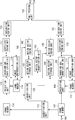
- Fig. 1 is a block diagram illustrating a configuration of an image coding apparatus according to a first exemplary embodiment.
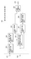
- Fig. 2 is a detailed block diagram of a motion vector coding unit 102 in the image coding apparatus according to the first exemplary embodiment.
- Fig. 3 is a detailed block diagram of a motion vector coding unit 105 in the image coding apparatus according to the first exemplary embodiment.
- Fig. 4 is a flowchart illustrating processing for coding a motion vector of a base layer by the image coding apparatus according to the first exemplary embodiment.
- Fig. 5 is a flowchart illustrating processing for coding a motion vector of an enhancement layer by the image coding apparatus according to the first exemplary embodiment.
- Fig. 6 is a diagram of an example of blocks and motion vectors.
- Fig. 7 is a block diagram illustrating a configuration of an image decoding apparatus according to a second exemplary embodiment.
- Fig. 8 is a detailed block diagram of a motion vector decoding unit 701 according to the second exemplary embodiment.
- Fig. 9 is a detailed block diagram of a motion vector decoding unit 704 according to the second exemplary embodiment.
- Fig. 10 is a flowchart illustrating processing for decoding a motion vector of a base layer by the image decoding apparatus according to the second exemplary embodiment.
- Fig. 11 is a flowchart illustrating processing for decoding a motion vector of an enhancement layer by the image decoding apparatus according to the second exemplary embodiment.
- FIG. 12 is a detailed block diagram of a motion vector coding unit 105 in an image coding apparatus according to a third exemplary embodiment.
- Fig. 13 is a flowchart illustrating processing for coding a motion vector of an enhancement layer by the image coding apparatus according to the third exemplary embodiment.
- Fig. 14 is a detailed block diagram of a motion vector decoding unit 704 according to a fourth exemplary embodiment.
- Fig. 15 is a flowchart illustrating processing for decoding a motion vector of an enhancement layer by an image decoding apparatus according to the fourth exemplary embodiment.
- Fig. 16 is a diagram of an example of blocks and motion vectors.
- Fig. 17 is a block diagram illustrating an example of a hardware configuration of a computer applicable to an image coding apparatus and a decoding apparatus of the exemplary embodiments of the present invention.
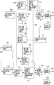
- Fig. 1 is a block diagram illustrating an image coding apparatus according to the present exemplary embodiment.
- image data is input to a terminal 106.
- a frame memory 107 stores the input image data picture by picture.
- a magnification unit 113 magnifies the input image data by a magnification n/m (n and m are positive numbers).
- a frame memory 114 stores the magnified image data picture by picture.
- Prediction units 108 and 115 segment image data into a plurality of blocks and perform intraframe prediction, such as intra prediction, and inter prediction by the motion compensation to generate predicted image data.
- the prediction methods are not limited thereto.
- the prediction units 108 and 115 further calculate prediction errors from the input image data and the predicted image data, and output the calculated prediction errors.
- the prediction units 108 and 115 refer to other coded pictures to calculate and output motion vectors.
- the prediction units 108 and 115 also output information needed for prediction, such as information about an intra prediction mode, along with the prediction errors.
- Transform and quantization units 109 and 116 orthogonally transform the prediction errors in units of blocks to obtain transform coefficients, and further perform quantization to obtain quantization coefficients.
- Frame memories 112 and 119 store reproduced image data.
- Image reproduction units 111 and 118 input the quantization coefficients in units of blocks, perform inverse quantization to obtain transform coefficients, and further perform inverse orthogonal transform to reproduce prediction errors.
- the image reproduction units 111 and 118 generate predicted image data from the motion vectors or prediction-related information from the prediction units 108 and 115 by referring to the frame memories 112 and 119 when necessary.
- the image reproduction units 111 and 118 finally generate reproduced image data from the resulting predicted image data and the reproduced prediction errors, and output the reproduced image data.
- Coefficient coding units 110 and 117 code the quantization coefficients output from the transform and quantization units 109 and 116 to generate quantization coefficient code data.
- a motion vector coding apparatus 100 includes motion vector storage units 101 and 104 which store motion vectors in units of blocks.
- the motion vector storage unit 104 stores motion vectors generated by the prediction unit 108.
- the motion vector storage unit 101 stores motion vectors generated by the prediction unit 115.
- Motion vector coding units 1102 and 105 code motion vectors in blocks generated by the prediction units 108 and 115 to generate motion vector code data.
- a motion vector magnification unit 103 magnifies a motion vector according to the magnification of the magnification unit 113.
- a magnification unit 120 magnifies the image data from the frame memory 119 by a reciprocal of the magnification of the magnification unit 113, i.e., m/n.
- Integration coding units 121 and 122 generate code data of header information and prediction-related information.
- the integration coding units 121 and 122 also integrate the motion vector code data generated by the motion vector coding units 102 and 105 with the quantization coefficient code data generated by the coefficient coding units 110 and 117.
- the frame memories 114 and 119, the prediction unit 115, the transform and quantization unit 116, the coefficient coding unit 117, the image reproduction unit 118, the motion vector storage unit 101, and the motion vector coding unit 102 code image data of a base layer.
- the frame memories 107 and 112, the prediction unit 108, the transform and quantization unit 109, the coefficient coding unit 110, the image reproduction unit 111, the motion vector storage unit 104, and the motion vector coding unit 105 code image data of an enhancement layer.
- a multiplexing unit 123 multiplexes the code data of the base layer and the code data of the enhancement layer to form a bit stream.
- a terminal 124 outputs the bit stream generated by the multiplexing unit 123 to outside.
- a single frame of image data input from the terminal 106 is stored into the frame memory 107.
- the magnification unit 113 magnifies the image data stored in the frame memory 107 by a predetermined magnification n/m. In the case of spatial scalability, the value of n/m is less than 1.
- the magnified image data is stored into the frame memory 114.
- the magnification is input to the magnification unit 120 and the motion vector magnification unit 103.
- the prediction unit 115 performs intra prediction or motion compensated inter prediction.
- the prediction unit 115 refers to a coded picture stored in the frame memory 119 and the block data of the base layer stored in the frame memory 114 to calculate a motion vector.
- the calculated motion vector is input to the image reproduction unit 118 and the motion vector storage unit 101.
- the motion vector storage unit 101 stores the motion vectors in units of blocks.
- the prediction unit 115 generates and inputs a prediction error to the transform and quantization unit 116.
- the transform and quantization unit 116 generates and inputs a quantization coefficient to the coefficient coding unit 117.
- the coefficient coding unit 117 performs entropy coding on the quantization coefficient to generate quantization coefficient code data.
- the entropy coding method is not limited in particular, and Golomb coding, arithmetic coding, and Huffman coding may be used.
- the quantization coefficient, the motion vector, and prediction-related information are input to the image reproduction unit 118.
- the image generation unit 118 generates a reproduced image of a block to be coded, and stores the reproduced image into the frame memory 119.
- the motion vector coding unit 102 codes the motion vector generated by the prediction unit 115 to generate motion vector code data.
- Fig. 2 illustrates a detailed block diagram of the motion vector coding unit 102.
- motion vector from the motion vector storage unit 101 is input to a terminal 201.
- a terminal 202 receives the motion vector in the block to be coded input from the prediction unit 115.
- a motion vector extraction unit 203 extracts motion vectors neighboring the block to be coded or a motion vector of a previously coded picture via the terminal 201.
- a motion vector integration unit 204 integrates motion vectors including the same components to generate a reference motion vector group.
- the integrated motion vectors are arranged in a predetermined order.
- the arrangement order is not limited in particular, and the integrated motion vectors may be arranged based on the order of the magnitude of the components, the descending order of the probability of occurrence, or the positions of the extracted blocks. Any arrangement method may be used as long as the same method is used on a decoding side.
- a predicted motion vector selection unit 205 receives the motion vector in the block to be coded from the terminal 202, and the reference motion vector group from the motion vector integration unit 204 as inputs.
- the predicted motion vector selection unit 205 selects a motion vector closest to the motion vector in the block to be coded from the input reference motion vector group as a predicted motion vector.
- the predicted motion vector selection unit 205 outputs an identification number for identifying the selected predicted motion vector in the reference motion vector group, and the selected predicted motion vector.
- An index coding unit 206 codes the output identification number to generate identification information code data.
- the method for coding the identification number is not limited in particular, and Golomb coding, arithmetic coding, and Huffman coding may be used.
- a prediction unit 207 outputs a prediction error that occurs when the motion vector in the block to be coded is predicted by the input predicted motion vector.
- a motion vector error coding unit 208 codes the prediction error of the motion vector to generate motion vector prediction error code data.
- the method for coding the prediction error of the motion vector is not limited in particular, and Golomb coding, arithmetic coding, and Huffman coding may be used.
- a code forming unit 209 shapes the identification information code data and the motion vector prediction error code data into motion vector code data.
- a terminal 201 outputs the generated motion vector code data to the integration coding unit 122 in Fig. 1.
- the motion vector extraction unit 203 receives motion vectors in neighboring blocks of a block to be coded of the base layer and a temporal direction predicted motion vector via the terminal 201. Such motion vectors are input to the motion vector integration unit 204.
- the motion vector integration unit 204 compares the components of the motion vectors and integrates the same ones to generate a reference motion vector group.
- Fig. 6 illustrates how motion vectors are extracted and integrated.
- An n-th picture 600 of the enhancement layer includes a block 603 to be coded. Blocks 604, 605, and 606 are adjacent to the block 603 to be coded.
- An (n - 1)-th picture 601 of the enhancement layer includes a block 607 that lies at the same position as the block 603.
- a motion vector 609 is included in the block 603 to be coded.
- Motion vectors 610, 611, 612, and 613 are included in the respective blocks 604, 605, 606, and 607. Suppose that the motion vectors 611 and 612 have the same components. In such a case, the resulting reference motion vector group includes the motion vectors 613, 612, and 610.
- the generated reference motion vector group is input to the predicted motion vector selection unit 205.
- the predicted motion vector selection unit 205 compares the motion vector in the block to be coded input from the terminal 202 and the motion vectors in the reference motion vector group.
- the predicted motion vector selection unit 205 selects a motion vector including the closest components to those of the motion vector in the block to be coded from the reference motion vector group as a predicted motion vector.
- the predicted motion vector selection unit 205 generates an identification number for indicating order to identify the selected motion vector in the reference motion vector group.
- the index coding unit 206 codes the identification number to generate identification information code data.
- the predicted motion vector is input to the prediction unit 207.
- the prediction unit 207 predicts the motion vector in the block to be coded, calculates a prediction error, and outputs the prediction error to the motion vector error coding unit 208.
- the motion vector error coding unit 208 codes the prediction error to generate motion vector prediction error code data.
- the code forming unit 209 shapes the identification information code data and the motion vector prediction error code data, and outputs the resulting motion vector code data from the terminal 210.
- the generated motion vector code data and the quantization coefficient code data generated by the coefficient coding unit 117 are input to the integration coding unit 122.
- the integration coding unit 122 generates code data in units of blocks.
- the generated code data is input to the multiplexing unit 123.
- the magnification unit 120 magnifies image data of the base layer, stored in the frame memory 119, by m/n to generate reference image data of the base layer.
- the prediction unit 108 divides the image data stored in the frame memory 107 into blocks, and performs intra prediction or motion compensated inter prediction block by block. In the case of inter prediction, the prediction unit 108 refers to a coded picture stored in the frame memory 112 and the reference image data of base layer to calculate a motion vector.
- the calculated motion vector is input to the image reproduction unit 111 and the motion vector storage unit 104.
- the motion vector storage unit 104 stores the motion vector in units of blocks.
- the prediction unit 108 generates and inputs a prediction error to the transform and quantization unit 109.
- the transform and quantization unit 109 generates and inputs a quantization coefficient to the coefficient coding unit 110. Similar to the coefficient coding unit 117, the coefficient coding unit 110 performs entropy coding on the quantization coefficient to generate quantization coefficient code data. The quantization coefficient, the motion vector, and prediction-related information are input to the image reproduction unit 111. Similar to the image reproduction unit 118, the image reproduction unit 111 generates a reproduced image of a block to be coded, and stores the reproduced image into the frame memory 112.
- the motion vector coding unit 105 codes the motion vector generated by the prediction unit 108 to generate motion vector code data.
- the motion vector magnification unit 103 Prior to the coding of a motion vector in the motion vector coding unit 105, the motion vector magnification unit 103 extracts a motion vector at the position of a block of the base layer corresponding to the block to be coded of the enhancement layer from the motion vector storage unit 101.
- the motion vector magnification unit 103 magnifies the extracted motion vector by m/n according to the magnification (n/m) output from the magnification unit 113, and outputs the resulting interlayer predicted motion vector to the motion vector coding unit 105.
- Fig. 6 illustrates how motion vectors are extracted and integrated.
- An n-th picture 602 of the base layer corresponding to the n-th picture 600 of the enhancement layer.
- a block 608 lies in a position corresponding to the block 603 to be coded of the enhancement layer.
- the block 608 of the base layer includes a motion vector 614.
- the motion vector 614 is magnified into an interlayer predicted motion vector which has the same precision as the resolution of the enhancement layer.
- the motion vectors 611 and 612 and the interlayer predicted motion vector have the same components.
- the resulting reference motion vector group includes the interlayer predicted motion vector and the motion vectors 613 and 610.
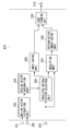
- Fig. 3 illustrates a detailed block diagram of the motion vector coding unit 105.
- a terminal 301 inputs an interlayer predicted motion vector from the motion vector magnification unit 103.
- a motion vector extraction unit 303 extracts motion vectors neighboring the block to be coded of the enhancement layer or a motion vector of a previously coded picture via the terminal 201, and adds the interlayer predicted motion vector from the terminal 301.
- a motion vector integration unit 304 integrates motion vectors including the same components to generate a reference motion vector group. In the reference motion vector group, the integrated motion vectors are arranged in a predetermined order.
- the arrangement order is not limited in particular, whereas the interlayer predicted motion vector is arranged at the top.
- the rest of the motion vectors may be arranged based on the order of the magnitude of the components, the descending order of the probability of occurrence, or the positions of the extracted blocks.
- the terminal 201 is connected to the motion vector storage unit 104.
- the terminal 202 is connected to the prediction unit 108.
- the terminal 210 is connected to the integration coding unit 121.
- the motion vector extraction unit 303 inputs motion vectors in neighboring blocks of the block of the base layer to be coded, a temporal direction predicted motion vector, and an interlayer predicted motion vector.
- the motion vector integration unit 304 compares the components of such motion vectors and integrates the same ones to generate a reference motion vector group. In the reference motion vector group, the integrated motion vectors are arranged in a predetermined order.
- the generated reference motion vector group is input to the predicted motion vector selection unit 205. Subsequently, similar to the motion vector coding unit 102 of the base layer, the motion vector in the block to be coded is compared with the motion vectors in the reference motion vector group to select a predicted motion vector. An identification number of the selected predicted motion vector is generated and coded to generate identification information code data.
- a prediction error of the motion vector in the block to be coded is calculated and coded to generate motion vector prediction error code data.
- the code forming unit 209 shapes the identification information code data and the motion vector prediction error code data, and outputs the resulting motion vector code data from the terminal 210.
- the generated motion vector code data and the quantization coefficient code data generated by the coefficient coding unit 110 are input to the integration coding unit 121.
- the integration coding unit 121 generates code data in units of blocks.
- the generated code data is input to the multiplexing unit 123.
- the multiplexing unit 123 multiplexes such code data according to a predetermined format, and outputs the resulting bit stream from the terminal 124 to outside.
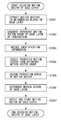
- Fig. 4 is a flowchart illustrating processing for coding a motion vector of a base layer by the image coding apparatus according to the first exemplary embodiment.
- the image coding apparatus inputs a motion vector in a block to be coded of the base layer, and stores the motion vector for reference in subsequent stages.
- the image coding apparatus extracts motion vectors in neighboring blocks of the block to be coded of the base layer or in a block at the same position of a coded picture of the base layer from stored coded motion vectors of the base layer.
- step S403 the image coding apparatus integrates motion vectors including the same components among the motion vectors extracted in step S402.
- the image coding apparatus rearranges the resultant in a predetermined order to generate a reference motion vector group.
- step S404 the image coding apparatus compares the reference motion vector group generated in step S403 with the motion vector in the block to be coded of the base layer to select the closest motion vector as a predicted motion vector of the base layer, and generates identification information.
- step S405 the image coding apparatus calculates a prediction error of the motion vector to be coded using the predicted motion vector.
- the image coding apparatus codes the identification information generated in step S404.
- the image coding apparatus codes the prediction error of the motion vector of the base layer.
- Fig. 5 is a flowchart illustrating processing for coding a motion vector of an enhancement layer by the image coding apparatus according to the first exemplary embodiment.
- steps for implementing similar functions to those of the steps in Fig. 4 are designated by the same reference numerals. Description thereof will be omitted.
- the image coding apparatus inputs a motion vector in a block to be coded of the enhancement layer, and stores the motion vector for reference in subsequent stages.
- step S502 the image coding apparatus extracts motion vectors in neighboring blocks of the block to be coded of the enhancement layer or in a block at the same position of a coded picture of the enhancement layer from stored motion vectors of the enhancement layer.
- step S503 the image coding apparatus extracts a motion vector in a block of the base layer corresponding to the position of the block to be coded of the enhancement layer.
- step S504 the image coding apparatus magnifies the extracted motion vector of the base layer to calculate an interlayer predicted motion vector.
- step S505 the image coding apparatus integrates motion vectors including the same components among the motion vectors extracted in step S502 and the interlayer predicted motion vector. The image coding apparatus rearranges the resultant in a predetermined order to generate a reference motion vector group.
- subsequent steps S404 to S407 similar to the coding of a motion vector of the base layer in Fig. 4, the image coding apparatus determines a predicted motion vector and generates identification information. The image coding apparatus further calculates a prediction error from the predicted motion vector. The image coding apparatus codes the generated identification information and the prediction error of the motion vector.
- the image coding apparatus can efficiently code the motion vector of the enhancement layer by using the motion vector of the base layer.
- the magnification factor is 1, the magnification units 113 and 120 and the motion vector magnification unit 103 may be omitted.
- the motion vector integration unit 204 may always allocate an interlayer predicted motion vector to the top of a reference motion vector group. Accordingly, chances for a shorter code to be assigned to an interlayer predicted motion vector which is highly likely to be referred to can be increased, and the coding efficiency can be further improved.
- the motion vector extraction unit 203 inputs a motion vector in a block at the same position of a picture in which a temporal direction predicted motion vector is coded.
- this is not restrictive.
- the input of a temporal direction predicted motion vector may be omitted if there is an interlayer predicted motion vector.
- the motion vector integration unit 304 is described to arrange an interlayer predicted motion vector at the top. However, the motion vector integration unit 304 may arrange an interlayer predicted motion vector after a temporal direction predicted motion vector. In addition, similar to the motion vector integration unit 204, the arrangement need not be particularly fixed.
- the motion vector integration units 204 and 304 integrate motion vectors including the same components in order to improve the coding efficiency.
- the motion vector integration units 204 and 304 are not limited to the above configuration.
- the motion vector integration units 204 and 304 may select a fixed number of motion vectors.
- the motion vector integration units 204 and 304 may even be omitted.
- a base layer coding apparatus and an enhancement layer coding apparatus may be provided separately, and the magnification units 113 and 120 may be provided outside of the image coding apparatus.
- the blocks lying in the positions illustrated in Fig. 6 are referred to for the motion vectors of the reference motion vector group.
- the blocks and the motion vectors are not limited to this example.
- a motion vector in a block adjacent to the right of the block 604 may be added.
- a motion vector corresponding to a median value of such motion vectors may be added.
- the motion vector to be referred to in the base layer is not limited to that of the same position, either.
- a motion vector 1604 in a block 1601 below the block 608, a motion vector 1605 in a block 1602 on the lower right, and a motion vector 1606 in a block 1603 on the right may be referred to.
- Motion vectors in other blocks may also be referred to.
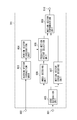
- Fig. 7 is a block diagram illustrating a configuration of an image decoding apparatus according to a second exemplary embodiment of the present invention.
- the present exemplary embodiment will be described using the decoding of code data generated in the first exemplary embodiment as an example.
- a terminal 706 inputs a coded bit stream.
- a separation unit 707 separates the bit stream into code data of the base layer and code data of the enhancement layer.
- the separation unit 707 performs an operation reverse to that of the multiplexing unit 123 in Fig. 1.
- Integration decoding units 708 and 715 decode code data on header information and prediction-related information about the base layer and the enhancement layer.
- the integration decoding units 708 and 715 separate quantization coefficient code data and motion vector code data, and output the resultant to subsequent stages.
- Coefficient decoding units 709 and 716 perform an operation reverse to that of the coefficient coding units 117 and 110 in Fig. 1 to reproduce quantization coefficients.
- Inverse quantization and inverse transform units 710 and 717 perform an operation reverse to that of the transform and quantization units 116 and 109 in Fig. 1.
- the inverse quantization and inverse transform units 710 and 717 reproduce orthogonal transform coefficients by inverse quantization, and generate prediction errors by inverse orthogonal transform.
- a motion vector decoding apparatus 700 includes vector decoding units 701 and 704.
- the motion vector decoding units 701 and 704 decode motion vector code data to reproduce motion vectors in blocks to be decoded.
- Motion vector storage units 702 and 705 store the motion vectors in units of blocks.
- a motion vector magnification unit 703 magnifies a motion vector according to the same magnification as that of the magnification unit 113 in Fig. 1.
- the method for calculating the magnification is not limited in particular.
- the ratio between the resolution of the base layer and that of the enhancement layer may be calculated.
- a predetermined value may be set.
- Frame memories 712, 713, 719, and 720 store image data of reproduced pictures.
- Image reproduction units 711 and 718 input the motion vectors, refer to image data on decoded pictures, perform motion compensation, and reproduce image data using the decoded prediction errors.
- a magnification unit 714 magnifies the image data of the base layer according to the same magnification as that of the magnification unit 113 in Fig. 1.
- the method for calculating the magnification is not limited in particular.
- the ratio between the resolution of the base layer and that of the enhancement layer may be calculated.
- a predetermined value may be set.
- a terminal 721 outputs the image data of the base layer.
- a terminal 722 outputs the image data of the enhancement layer.
- the integration decoding unit 708, the coefficient decoding unit 708, the inverse quantization and inverse transform unit 710, the motion vector decoding unit 701, the motion vector storage unit 702, the image reproduction unit 711, and the frame memories 712 and 713 decode the code data of the base layer and reproduce the image data of the base layer.
- the integration decoding unit 715, the coefficient decoding unit 716, the inverse quantization and inverse transform unit 717, the motion vector decoding unit 704, the motion vector storage unit 705, the image reproduction unit 718, and the frame memories 719 and 720 decode the code data of the enhancement layer and reproduce the image data of the enhancement layer.
- the image decoding apparatus decodes a bit stream generated in the first exemplary embodiment.
- bit stream input from the terminal 706 is input to the separation unit 707.
- the separation unit 707 separates the bit stream into code data of the base layer and code data of the enhancement layer.
- the former is input to the integration decoding unit 708.
- the latter is input to the integration decoding unit 715.
- the code data of the base layer is input to the integration decoding unit 708.
- the integration decoding unit 708 decodes the code data on header information and prediction-related information, separates quantization coefficient code data and motion vector code data, inputs the motion vector code data to the motion vector decoding unit 701, and inputs the quantization coefficient code data to the coefficient decoding unit 709.
- the coefficient decoding unit 709 decodes the quantization coefficient code data to reproduce a quantization coefficient.
- the reproduced quantization coefficient is input to the inverse quantization and inverse transform unit 710.
- the inverse quantization and inverse transform unit 710 performs inverse quantization on the reproduced quantization coefficient to generate an orthogonal transform coefficient, and further applies inverse orthogonal transform thereto to reproduce a prediction error.
- the reproduced prediction error is input to the image reproduction unit 711.
- the motion vector decoding unit 701 decodes the motion vector code data to reproduce a motion vector in a block to be decoded of the base layer.
- Fig. 8 illustrates a detailed block diagram of the motion vector decoding unit 701.
- a terminal 801 inputs the motion vector code data of the block to be decoded from the integration decoding unit 708.
- a terminal 802 inputs a motion vector from the motion vector storage unit 702.
- a motion vector extraction unit 803 extracts motion vectors neighboring the block to be decoded of the base layer or a motion vector of a previously decoded picture via the terminal 802.
- a motion vector integration unit 804 performs a similar operation to that of the motion vector integration unit 204 in Fig. 2. That is, the motion vector integration unit 804 integrates motion vectors including the same components to generate a reference motion vector group.
- a code separation unit 805 separates the motion vector code data into identification information code data and motion vector prediction error code data.
- An index decoding unit 806 decodes the identification information code data to reproduce identification information. The index decoding unit 806 performs an operation reverse to that of the index coding unit 206 in Fig. 2 for decoding.
- a motion vector error decoding unit 807 decodes the motion vector prediction error code data to reproduce the prediction error of the motion vector in the block to be decoded.
- the motion vector error decoding unit 807 performs an operation reverse to that of the motion vector error coding unit 208 in Fig. 2 for decoding.
- a predicted motion vector selection unit 808 selects a predicted motion vector from the reference motion vector group using the reproduced identification information.
- a motion vector reproduction unit 809 reproduces the motion vector in the block to be decoded of the base layer from the selected predicted motion vector and the reproduced prediction error of the motion vector.
- a terminal 810 outputs the reproduced motion vector to the image reproduction unit 711 and the motion vector storage unit 702 in Fig. 7.
- the motion vector code data of the block to be decoded of the base layer input from the terminal 801 is input to the code separation unit 805.
- the code separation unit 805 separates the motion vector code data into identification information code data and motion vector prediction error code data.
- the former is input to the index decoding unit 806.
- the latter is input to the motion vector error decoding unit 807.
- the index decoding unit 806 decodes the identification information code data to reproduce identification information.
- the motion vector error decoding unit 807 decodes the motion vector prediction error code data to reproduce the prediction error of the motion vector in the block to be decoded of the base layer.
- the motion vector extraction unit 803 extracts the motion vectors in the neighboring blocks of the block of the base layer to be decoded and the temporal direction predicted motion vector from the motion vector storage unit 702 via the terminal 802.
- the extracted motion vectors are input to the motion vector integration unit 804.
- the motion vector integration unit 804 generates a reference motion vector group similar to the motion vector integration unit 204 in Fig. 2.
- the predicted motion vector selection unit 808 inputs the identification information from the index decoding unit 806 and selects a predicted motion vector from the reference motion vector group.
- the selected predicted motion vector is input to the motion vector generation unit 809 together with the reproduced prediction error of the motion vector in the block to be decoded of the base layer.
- the motion vector reproduction unit 809 reproduces the motion vector in the block to be decoded from the reproduced prediction error and the predicted motion vector.
- the reproduced motion vector is output via the terminal 810.
- the reproduced motion vector is input to the image reproduction unit 711 and the motion vector storage unit 702.
- the motion vector storage unit 702 stores motion vectors in units of blocks.
- the image reproduction unit 711 calculates predicted image data of the block to be decoded of the base layer using the reproduced motion vector and based on the frame memory 713.
- the image reproduction unit 711 further is input the prediction error reproduced by the inverse quantization and inverse transform unit 710, and reproduces image data of the base layer using the predicted image data.
- the reproduced image data of the base layer is stored into the frame memories 712 and 713 and used for reference.
- the reproduced image data of the base layer is output from the terminal 721.
- the motion vector magnification unit 703 Prior to the decoding of a motion vector by the motion vector decoding unit 704, the motion vector magnification unit 703 extracts a motion vector at the position of a block of the base layer corresponding to the block to be decoded of the enhancement layer from the motion vector storage unit 702. The motion vector magnification unit 703 magnifies the extracted motion vector by m/n according to the magnification (n/m), and outputs the resulting interlayer predicted motion vector to the motion vector decoding unit 704.
- the code data of the enhancement layer is input to the integration decoding unit 715.
- the integration decoding unit 715 decodes the code data on header information and prediction-related information, separates quantization coefficient code data and motion vector code data, inputs the motion vector code data to the motion vector decoding unit 704, and inputs the quantization coefficient code data to the coefficient decoding unit 716.
- the coefficient decoding unit 716 decodes the quantization coefficient code data to reproduce a quantization coefficient.
- the reproduced quantization coefficient is input to the inverse quantization and inverse transform unit 717.
- the inverse quantization and inverse transform unit 717 performs inverse quantization on the reproduced quantization coefficient to generate an orthogonal transform coefficient, and further applies inverse orthogonal transform thereto to reproduce a prediction error.
- the reproduced prediction error is input to the image reproduction unit 718.
- the motion vector decoding unit 704 decodes the motion vector code data to reproduce the motion vector in the block to be decoded of the enhancement layer.
- Fig. 9 illustrates a detailed block diagram of the motion vector decoding unit 704.
- blocks implementing similar functions to those of the blocks in Fig. 8 are designated by the same reference numerals. Description thereof will be omitted.
- a terminal 901 inputs a motion vector from the motion vector magnification unit 703.
- a motion vector extraction unit 903 is input motion vectors neighboring the block to be decoded of the enhancement layer or a motion vector of a previously decoded picture as illustrated in Fig. 6 via the terminal 901.
- the motion vector extraction unit 903 is also input the interlayer predicted motion vector input from the terminal 901.
- a motion vector integration unit 904 performs a similar operation to that of the motion vector integration unit 804 in Fig. 8. That is, the motion vector integration unit 904 integrates motion vectors including the same components to generate a reference motion vector group.
- the integrated motion vectors are arranged in a predetermined order.
- the arrangement order is not limited in particular, whereas the interlayer predicted motion vector is arranged at the top.
- the rest of the motion vectors may be arranged based on the order of the magnitude of the components, the descending order of the probability of occurrence, or the positions of the extracted blocks.
- a terminal 801 is connected to the integration decoding unit 715.
- a terminal 802 is connected to the motion vector storage unit 705.
- a terminal 810 is connected to the motion vector storage unit 705 and the image reproduction unit 718.
- the motion vector extraction unit 903 is input motion vectors in neighboring blocks of the block to be decoded of the enhancement layer and a temporal direction predicted motion vector from the motion vector storage unit 705 via the terminal 802.
- the motion vector extraction unit 903 is further input an interlayer predicted motion vector from the terminal 901.
- Such motion vectors are input to the motion vector integration unit 904.
- the motion vector integration unit 904 generates a reference motion vector group similar to the motion vector integration unit 804 in Fig. 8. Subsequently, similar to the motion vector decoding unit 701 of the base layer, the motion vector decoding unit 704 selects a predicted motion vector from the reference motion vector group based on the identification information.
- the motion vector decoding unit 704 reproduces the motion vector in the block to be decoded of the enhancement layer using the selected predicted motion vector and the reproduced prediction error of the motion vector in the block to be decoded of the enhancement layer.
- the reproduced motion vector is output via the terminal 810.
- the reproduced motion vector is input to the image reproduction unit 718 and the motion vector storage unit 705.
- the motion vector storage unit 705 stores motion vectors in units of blocks.
- the image reproduction unit 718 is input the image data magnified by the magnification unit 714 by reading corresponding image data from the frame memory 713 or the image data by reading the frame memory 713 using the reproduced motion vector.
- the image reproduction unit 718 calculates predicted image data of the block to be decoded of the enhancement layer from the image data.
- the image reproduction unit 718 is further inputs the prediction error reproduced by the inverse quantization and inverse transform unit 717, and reproduces image data of the enhancement layer using the predicted image data.
- the reproduced image data of the enhancement layer is stored in the frame memories 719 and 720 and used for reference.
- the reproduced image data of the enhancement layer is output from the terminal 722.
- Fig. 10 is a flowchart illustrating processing for decoding a motion vector of the base layer by the image decoding apparatus according to the second exemplary embodiment.
- the image decoding apparatus extracts motion vectors in neighboring blocks of the block to be decoded of the base layer and a temporal direction predicted motion vector from stored motion vectors.
- the image decoding apparatus integrates motion vectors including the same components among the motion vectors extracted in step S1001, and rearranges the resultant in a predetermined order to generate a reference motion vector group.
- step S1003 the image decoding apparatus decodes identification information code data to reproduce identification information.
- step S1004 the image decoding apparatus selects a predicted motion vector from the reference motion vector group generated in step S1002 based on the identification information reproduced in step S1003.
- step S1005 the image decoding apparatus decodes motion vector prediction error code data to reproduce the prediction error of the motion vector in the block to be decoded of the base layer.
- step S1006 the image decoding apparatus reproduces the motion vector in the block to be decoded of the base layer from the predicted motion vector selected in step S1004 and the prediction error of the motion vector reproduced in step S1005.
- step S1007 the image decoding apparatus outputs the reproduced motion vector, and stores the motion vector for reference in subsequent stages.
- Fig. 11 is a flowchart illustrating processing for decoding a motion vector of the enhancement layer by the image decoding apparatus according to the second exemplary embodiment.
- steps for implementing similar functions to those of the steps in Fig. 10 are designated by the same reference numerals. Description thereof will be omitted.
- step S1101 the image decoding apparatus extracts motion vectors in neighboring blocks of the block to be decoded of the enhancement layer or a temporal direction predicted motion vector of the enhancement layer from stored decoded motion vectors of the enhancement layer.
- step S1102 the image decoding apparatus extracts a motion vector in a block of the base layer corresponding to the position of the block to be decoded of the enhancement layer.
- step S1103 the image decoding apparatus magnifies the extracted motion vector of the base layer to calculate an interlayer predicted motion vector.
- step S1104 the image decoding apparatus integrates motion vectors including the same components among the motion vectors extracted in step S1102 and the interlayer predicted motion vector, and rearranges the resultant in a predetermined order to generate a reference motion vector group.
- step S1105 the image decoding apparatus decodes identification information code data to reproduce identification information.
- step S1106 the image decoding apparatus selects a predicted motion vector from the reference motion vector group generated in step S1104 based on the reproduced identification information. Subsequently, similar to the decoding of the motion vector of the base layer in Fig. 10, the image decoding apparatus decodes motion vector prediction error code data to reproduce the prediction error of the motion vector. The image decoding apparatus reproduces the motion vector in the block to be decoded of the enhancement layer from the selected predicted motion vector and the prediction error of the motion vector. The image decoding apparatus outputs and stores the reproduced motion vector.
- a bit stream which is generated in the first exemplary embodiment and efficiently coded using the motion vectors of the base layer can be decoded to obtain a reproduced image.
- the magnification factor is 1, the magnification unit 714 and the motion vector magnification unit 703 may be omitted.
- the motion vector integration unit 904 may always allocate an interlayer predicted motion vector to the top of a reference motion vector group. Accordingly, chances for a shorter code to be assigned to an interlayer predicted motion vector which is highly likely to be referred to can be increased, and the decoding efficiency can be further improved.
- the motion vector extraction unit 903 inputs a temporal direction predicted motion vector.
- this is not restrictive.
- the input of a temporal direction predicted motion vector may be omitted if there is an interlayer predicted motion vector.
- the motion vector integration unit 904 is described to arrange an interlayer predicted motion vector at the top. However, the motion vector integration unit 904 may arrange the interlayer predicted motion vector after a temporal direction predicted motion vector. In addition, similar to the motion vector integration unit 204, the arrangement need not be particularly fixed.
- the magnification is input from the motion vector magnification unit 703.
- the input of the magnification is not limited to this example.
- the ratio between the resolution of the base layer and that of the enhancement layer may be independently calculated.
- a predetermined value may be set.
- the motion vector integration units 804 and 904 integrate motion vectors including the same components in order to improve the coding efficiency of coded data.
- the motion vector integration units 804 and 904 are not limited to this configuration.
- the motion vector integration units 804 and 904 may select a fixed number of motion vectors.
- the motion vector integration units 804 and 904 may even be omitted.
- a base layer decoding apparatus and an enhancement layer decoding apparatus may be provided separately, and the magnification unit 714 may be provided outside of the image decoding apparatus.
- the blocks lying in the positions illustrated in Fig. 6 are referred to for the motion vectors of the reference motion vector group.
- the blocks and the motion vectors are not limited to this example.
- a motion vector in a block adjacent to the right of the block 604 may be added.
- a motion vector corresponding to a median value of such motion vectors may be added.
- the motion vector to be referred to in the base layer is not limited to that of the same position, either.
- a motion vector 1604 in a block 1601 below the block 608, a motion vector 1605 in a block 1602 on the lower right, and a motion vector 1606 in a block 1603 on the right may be referred to.
- Motion vectors in other blocks may also be referred to.
- An image coding apparatus includes a similar configuration to that in Fig. 1 according to the first exemplary embodiment. A difference lies in the configuration of the motion vector coding unit 105 of the enhancement layer.
- the coding of the base layer and the coding of the quantization coefficient of the enhancement layer are the same as in the first exemplary embodiment, and description thereof will be omitted.
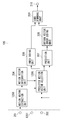
- Fig. 12 is a block diagram illustrating a detailed configuration of the motion vector coding unit 105 according to the present exemplary embodiment.
- parts implementing similar functions to those in Fig. 3 according to the first exemplary embodiment are designated by the same reference numerals. Description thereof will be omitted.
- a terminal 1201 Similar to the terminal 301 in Fig. 3, a terminal 1201 inputs an interlayer predicted motion vector from the motion vector magnification unit 103.
- a motion vector extraction unit 1203 extracts motion vectors neighboring the block to be coded of the enhancement layer or a motion vector of a previously coded picture which are input from the terminal 201.
- a predicted motion vector selection unit 1205 is input a motion vector in the block to be coded of the enhancement layer from the terminal 202, a reference motion vector group from the motion vector integration unit 304, and the interlayer predicted motion vector from the terminal 1201.
- the predicted motion vector selection unit 1205 selects a motion vector closest to the motion vector in the block to be coded from the input reference motion vector group as a predicted motion vector.
- the motion vector extraction unit 1203 extracts the motion vectors neighboring the block to be coded of the enhancement layer or the motion vector of the previously coded picture illustrated in Fig. 6.
- the extracted motion vector is input to the motion vector integration unit 304. Similar to the first exemplary embodiment, the motion vector integration unit 304 integrates motion vectors including the same components among the input motion vectors to generate a reference motion vector group.
- the predicted motion vector selection unit 1205 selects a motion vector most similar to the motion vector in the block to be coded from the input reference motion vector group and the interlayer predicted motion vector as a predicted motion vector.
- the predicted motion vector selection unit 1205 outputs identification information for identifying the selected predicted motion vector, and the predicted motion vector.
- a difference from the first exemplary embodiment lies in that the interlayer predicted motion vector is handled as a selection candidate independent of the reference motion vector group.
- the reference motion vector group may thus include a motion vector including the same components as those of the interlayer predicted motion vector. Therefore, the predicted motion vector selection unit 1205 is configured to select the interlayer predicted motion vector as a predicted motion vector if both the interlayer predicted motion vector and the motion vector in the reference motion vector group can be selected.
- the index coding unit 206 codes identification information.
- the prediction unit 207 calculates a prediction error from the motion vector in the block to be coded and the predicted motion vector.
- the motion vector error coding unit 208 codes the prediction error.
- Fig. 13 is a flowchart illustrating processing for coding a motion vector of the enhancement layer by the image coding apparatus according to the third exemplary embodiment.
- steps for implementing similar functions to those of the steps in Fig. 5 are designated by the same reference numerals. Description thereof will be omitted.
- the image coding apparatus extracts motion vectors neighboring the block to be coded of the enhancement layer or a moving vector in a block at the same position of a coded picture of the enhancement layer from stored motion vectors of the enhancement layer, and calculates an interlayer predicted motion vector.
- the image coding apparatus integrates motion vectors including the same components among the motion vectors neighboring the block to be coded of the enhancement layer or the motion vector of the previously coded picture, and rearranges the resultant in a predetermined order to generate a reference motion vector group.
- the image coding apparatus adds the interlayer predicted motion vector to the top of the generated reference motion vector group.
- step S404 the image coding apparatus selects a predicted motion vector from the reference motion vector group similar to the first exemplary embodiment.
- step S1303 if the predicted motion vector includes the same components as those of the interlayer predicted motion vector (YES in step S1303), the processing proceeds to step S1304. Whereas if not (NO in step S1303), the processing proceeds to step S405.
- step S1304 the image coding apparatus selects the interlayer predicted motion vector as a predicted motion vector. Accordingly, the other motion vector including the same components may be prevented from being selected.
- steps S405 to S407 similar to the processing for coding the motion vector of the enhancement layer in Fig. 5 according to the first exemplary embodiment, the image coding apparatus calculates the prediction error of the motion vector, codes the identification information, and codes the prediction error of the motion vector.
- the image coding apparatus can efficiently code the motion vector of the enhancement layer by preferentially using the motion vector of the base layer over other motion vectors. This is because the interlayer predicted motion vector has extremely highly correlation with the motion vector in the block of the enhancement layer.
- the blocks lying in the positions illustrated in Fig. 6 are referred to for the motion vectors of the reference motion vector group.
- the blocks and the motion vectors are not limited to this example.
- a motion vector in a block adjacent to the right of the block 604 may be added.
- a motion vector corresponding to a median value of such motion vectors may be added.
- the motion vector integration units 204 and 304 integrate motion vectors including the same components in order to improve the coding efficiency.
- the motion vector integration units 204 and 304 are not limited to the above configuration.
- the motion vector integration units 204 and 304 may select a fixed number of motion vectors.
- the motion vector integration units 204 and 304 may even be omitted.
- An image decoding apparatus includes a similar configuration to that in Fig. 7 according to the second exemplary embodiment.
- a difference lies in the configuration of the motion vector decoding unit 704 of the enhancement layer.
- the decoding of the base layer and the decoding of the quantization coefficient of the enhancement layer are the same as in the second exemplary embodiment, and description thereof will be omitted.
- the present exemplary embodiment will be described by using the decoding of code data generated in the third exemplary embodiment as an example.
- Fig. 14 is a block diagram illustrating a detailed configuration of the motion vector decoding unit 704 according to the present exemplary embodiment.
- a terminal 1401 inputs an interlayer predicted motion vector from the motion vector magnification unit 703.
- a motion vector extraction unit 1403 extracts motion vectors neighboring the block to be decoded of the enhancement layer or a motion vector of a previously decoded picture.
- a predicted motion vector selection unit 1405 selects a predicted motion vector from an interlayer predicted motion vector and a reference motion vector group according to identification information.
- the motion vector extraction unit 1403 extracts the motion vectors neighboring the block to be decoded of the enhancement layer or the motion vector of the previously decoded picture illustrated in Fig. 6.
- the extracted motion vector is input to the motion vector integration unit 804.
- the motion vector integration unit 804 integrates motion vectors including the same components among the input motion vectors to generate a reference motion vector group.
- the index decoding unit 806 decodes identification information code data to reproduce identification information.
- the predicted motion vector selection unit 1405 selects a predicted motion vector from an interlayer predicted motion vector and the reference motion vector group according to the identification information.
- the image decoding apparatus reproduces the motion vector to be decoded of the enhancement layer from the prediction error of the motion vector and the selected predicted motion vector.
- Fig. 15 is a flowchart illustrating processing for decoding a motion vector of the enhancement layer by the image decoding apparatus according to the fourth exemplary embodiment.
- steps for implementing similar functions to those of the steps in Fig. 11 are designated by the same reference numerals. Description thereof will be omitted.
- processing in steps S1101 to S1103 are similar to those of the second exemplary embodiment. More specifically, the image decoding apparatus extracts motion vectors neighboring the block to be decoded of the enhancement layer or a motion vector of a previously decoded picture, and calculates an interlayer predicted motion vector.
- step S1501 the image decoding apparatus integrates motion vectors including the same components among the motion vectors neighboring the block to be decoded of the enhancement layer or the motion vector of the previously decoded picture, and rearranges the resultant to generate a reference motion vector group.
- step S1502 the image decoding apparatus adds the interlayer predicted motion vector to the top of the generated reference motion vector group.
- the image decoding apparatus performs the processing in steps S1105 to S1007. More specifically, the image decoding apparatus decodes identification information, selects a predicted motion vector, reproduces the prediction error of the motion vector, and reproduces the motion vector in the block to be decoded of the enhancement layer.
- the image decoding apparatus can decode code data of the enhancement layer that is coded with a smaller amount of code by preferentially using the motion vector of the base layer over other motion vectors. This is because the interlayer predicted motion vector has extremely highly correlation with the motion vector in the block of the enhancement layer.
- the motion vector integration units 804 and 904 integrate motion vectors including the same components in order to improve the coding efficiency of coded data.
- the motion vector integration units 804 and 904 are not limited to this configuration.
- the motion vector integration units 804 and 904 may select a fixed number of motion vectors.
- the motion vector integration units 804 and 904 may even be omitted.
- the blocks lying in the positions illustrated in Fig. 6 are referred to for the motion vectors of the reference motion vector group.
- the blocks and the motion vectors are not limited to this example.
- each of the processing units illustrated in Figs. 1, 2, 3, 7, 8, 9, 12, and 14 are described to be implemented by hardware.
- the processing performed by the processing units illustrated in these drawings may be implemented by a computer program.
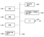
- Fig. 17 is a block diagram illustrating an example of hardware configuration of a computer that is applicable to the image coding or decoding apparatus according to the above-described exemplary embodiments.
- a central processing unit (CPU) 1701 controls the entire computer with use of a computer program and data stored in a random access memory (RAM) 1702 and a read-only memory (ROM) 1703. Further, the CPU 1701 executes the processing that is described to be performed by the image coding or decoding apparatus according to the above-described exemplary embodiments. In other words, the CPU 1701 functions as the respective processing units illustrated in Figs. 1, 2, 3, 7, 8, 9, 12, and 14.
- the RAM 1702 includes an area for temporarily storing a computer program and data loaded from an external storage device 1706 and data acquired from outside via an interface (I/F) 1707.
- the RAM 1702 further includes a work area for the CPU 1701 to use when executing various types of processing.
- the RAM 1702 can be allocated as a frame memory and can provide various other areas according to need.
- the ROM 1703 stores setting data and a boot program of the computer.
- An operation unit 1704 includes a keyboard and a mouse. A user of the computer can operate the operation unit 1704 to input various instructions to the CPU 1701.
- a display unit 1705 displays the result of processing of the CPU 1701.
- the display unit 1705 may include, for example, a liquid crystal display.
- the external storage device 1706 is a large-capacity information storage device, typified by a hard disk drive.
- the external storage device 1706 stores an operating system (OS) and the computer program for causing the CPU 1701 to implement the functions of the respective units illustrated in Figs. 1, 2, 3, 7, 8, 9, 12, and 14.
- the external storage device 1706 may further store pieces of image data to be processed.
- the computer program and data stored in the external storage device 1706 may be loaded into the RAM 1702 according to the control of the CPU 1701 when needed, and processed by the CPU 1701.
- Networks such as a local area network (LAN) and the Internet and other devices such as a projection apparatus and a display apparatus may be connected to the I/F 1707.
- the computer can acquire and transmit various information via the I/F 1707.
- a bus 1708 connects the above-described components.
- the CPU 1701 principally controls the operations described in the above-described flowcharts.
- An exemplary embodiment of the present invention may be achieved by supplying a storage medium storing computer program code for implanting the above-described functions to a system, and reading and executing the computer program code by the system.
- the computer program code itself read from the storage medium implements the functions of the above-described exemplary embodiments while the storage medium storing the computer program code constitutes the exemplary embodiment of the present invention.
- An exemplary embodiment of the present invention also covers situations where an operating system (OS) running on the computer executes a part or all of the actual processes based on instructions of the program code and the above-described functions are implemented such the processing.
- OS operating system
- the above-described functions may be implemented in the following mode.
- the computer program code read from the storage medium is written into a memory equipped in a function expansion card inserted in the computer or a function expansion unit connected to the computer.
- a CPU of the function expansion card or the function expansion unit executes a part or all of the actual processing to implement the above-described functions.
- the storage medium stores the computer program code corresponding to the above-described flowcharts.
Landscapes
- Engineering & Computer Science (AREA)
- Multimedia (AREA)
- Signal Processing (AREA)
- Compression Or Coding Systems Of Tv Signals (AREA)
Priority Applications (6)
| Application Number | Priority Date | Filing Date | Title |
|---|---|---|---|
| CN201280054782.6A CN103931191B (zh) | 2011-11-07 | 2012-10-31 | 运动矢量编码设备、运动矢量编码方法和程序、运动矢量解码设备以及运动矢量解码方法和程序 |
| US14/356,529 US9681126B2 (en) | 2011-11-07 | 2012-10-31 | Motion vector coding apparatus, method and program for coding motion vector, motion vector decoding apparatus, and method and program for decoding motion vector |
| CN201810385506.7A CN108347617B (zh) | 2011-11-07 | 2012-10-31 | 编码设备 |
| US15/391,640 US10045045B2 (en) | 2011-11-07 | 2016-12-27 | Motion vector coding apparatus, method and program for coding motion vector, motion vector decoding apparatus, and method and program for decoding motion vector |
| US16/030,621 US10397567B2 (en) | 2011-11-07 | 2018-07-09 | Motion vector coding apparatus, method and program for coding motion vector, motion vector decoding apparatus, and method and program for decoding motion vector |
| US16/528,302 US10986333B2 (en) | 2011-11-07 | 2019-07-31 | Motion vector coding apparatus, method and program for coding motion vector, motion vector decoding apparatus, and method and program for decoding motion vector |
Applications Claiming Priority (2)
| Application Number | Priority Date | Filing Date | Title |
|---|---|---|---|
| JP2011243936A JP5950541B2 (ja) | 2011-11-07 | 2011-11-07 | 動きベクトル符号化装置、動きベクトル符号化方法及びプログラム、動きベクトル復号装置、動きベクトル復号方法及びプログラム |
| JP2011-243936 | 2011-11-07 |
Related Child Applications (2)
| Application Number | Title | Priority Date | Filing Date |
|---|---|---|---|
| US14/356,529 A-371-Of-International US9681126B2 (en) | 2011-11-07 | 2012-10-31 | Motion vector coding apparatus, method and program for coding motion vector, motion vector decoding apparatus, and method and program for decoding motion vector |
| US15/391,640 Continuation US10045045B2 (en) | 2011-11-07 | 2016-12-27 | Motion vector coding apparatus, method and program for coding motion vector, motion vector decoding apparatus, and method and program for decoding motion vector |
Publications (1)
| Publication Number | Publication Date |
|---|---|
| WO2013069231A1 true WO2013069231A1 (en) | 2013-05-16 |
Family
ID=47216382
Family Applications (1)
| Application Number | Title | Priority Date | Filing Date |
|---|---|---|---|
| PCT/JP2012/006987 WO2013069231A1 (en) | 2011-11-07 | 2012-10-31 | Motion vector coding apparatus, method and program for coding motion vector, motion vector decoding apparatus, and method and program for decoding motion vector |
Country Status (4)
| Country | Link |
|---|---|
| US (4) | US9681126B2 (ja) |
| JP (1) | JP5950541B2 (ja) |
| CN (6) | CN108600763B (ja) |
| WO (1) | WO2013069231A1 (ja) |
Cited By (5)
| Publication number | Priority date | Publication date | Assignee | Title |
|---|---|---|---|---|
| WO2014050104A1 (en) * | 2012-09-28 | 2014-04-03 | Sharp Kabushiki Kaisha | Motion derivation and coding for scaling video |
| GB2512829A (en) * | 2013-04-05 | 2014-10-15 | Canon Kk | Method and apparatus for encoding or decoding an image with inter layer motion information prediction according to motion information compression scheme |
| US9392268B2 (en) | 2012-09-28 | 2016-07-12 | Qualcomm Incorporated | Using base layer motion information |
| US9420286B2 (en) | 2012-06-15 | 2016-08-16 | Qualcomm Incorporated | Temporal motion vector prediction in HEVC and its extensions |
| RU2737315C1 (ru) * | 2016-02-06 | 2020-11-27 | Хуавей Текнолоджиз Ко., Лтд. | Способ и устройство кодирования изображения и способ и устройство декодирования изображения |
Families Citing this family (6)
| Publication number | Priority date | Publication date | Assignee | Title |
|---|---|---|---|---|
| JP5950541B2 (ja) * | 2011-11-07 | 2016-07-13 | キヤノン株式会社 | 動きベクトル符号化装置、動きベクトル符号化方法及びプログラム、動きベクトル復号装置、動きベクトル復号方法及びプログラム |
| CN109257601A (zh) | 2012-07-03 | 2019-01-22 | 夏普株式会社 | 图像解码装置以及图像编码装置 |
| EP3687173A1 (en) * | 2012-09-03 | 2020-07-29 | Sony Corporation | Image processing device and method with inter-layer motion vector compression |
| JP5987615B2 (ja) * | 2012-09-28 | 2016-09-07 | 株式会社Jvcケンウッド | 画像復号装置、画像復号方法、画像復号プログラム、受信装置、受信方法及び受信プログラム |
| JP2015128205A (ja) * | 2013-12-27 | 2015-07-09 | ソニー株式会社 | 復号装置および復号方法、並びに、符号化装置および符号化方法 |
| US20220279204A1 (en) * | 2021-02-26 | 2022-09-01 | Qualcomm Incorporated | Efficient video encoder architecture |
Citations (1)
| Publication number | Priority date | Publication date | Assignee | Title |
|---|---|---|---|---|
| US20060153300A1 (en) * | 2005-01-12 | 2006-07-13 | Nokia Corporation | Method and system for motion vector prediction in scalable video coding |
Family Cites Families (23)
| Publication number | Priority date | Publication date | Assignee | Title |
|---|---|---|---|---|
| JP2000013790A (ja) * | 1998-06-19 | 2000-01-14 | Sony Corp | 画像符号化装置および画像符号化方法、画像復号装置および画像復号方法、並びに提供媒体 |
| US7929610B2 (en) * | 2001-03-26 | 2011-04-19 | Sharp Kabushiki Kaisha | Methods and systems for reducing blocking artifacts with reduced complexity for spatially-scalable video coding |
| EP1574995A1 (en) * | 2004-03-12 | 2005-09-14 | Thomson Licensing S.A. | Method for encoding interlaced digital video data |
| KR100913260B1 (ko) * | 2004-07-01 | 2009-08-21 | 콸콤 인코포레이티드 | 규모 가변적 비디오 코딩에서 프레임 레이트 업 변환을 이용하는 방법 및 장치 |
| CN101023672A (zh) * | 2004-07-12 | 2007-08-22 | 诺基亚公司 | 在可调整视频编码中用于运动预测的系统和方法 |
| TWI268715B (en) * | 2004-08-16 | 2006-12-11 | Nippon Telegraph & Telephone | Picture encoding method, picture decoding method, picture encoding apparatus, and picture decoding apparatus |
| WO2006080662A1 (en) * | 2004-10-21 | 2006-08-03 | Samsung Electronics Co., Ltd. | Method and apparatus for effectively compressing motion vectors in video coder based on multi-layer |
| KR100664929B1 (ko) * | 2004-10-21 | 2007-01-04 | 삼성전자주식회사 | 다 계층 기반의 비디오 코더에서 모션 벡터를 효율적으로압축하는 방법 및 장치 |
| KR100885443B1 (ko) * | 2005-04-06 | 2009-02-24 | 엘지전자 주식회사 | 레이어간 예측방식를 사용해 엔코딩된 영상신호를디코딩하는 방법 |
| WO2007018688A1 (en) * | 2005-07-22 | 2007-02-15 | Thomson Licensing | Method and apparatus for weighted prediction for scalable video coding |
| EP1809041A1 (en) * | 2006-01-11 | 2007-07-18 | Mitsubishi Electric Information Technology Centre Europe B.V. | Error concealement for scalable video coding |
| CN101198064A (zh) * | 2007-12-10 | 2008-06-11 | 武汉大学 | 一种分辨率分层技术中的运动矢量预测方法 |
| ES2812473T3 (es) | 2008-03-19 | 2021-03-17 | Nokia Technologies Oy | Vector de movimiento combinado y predicción de índice de referencia para la codificación de vídeo |
| EP2136565A1 (en) * | 2008-06-19 | 2009-12-23 | Thomson Licensing | Method for determining a filter for interpolating one or more pixels of a frame, method for encoding or reconstructing a frame and method for transmitting a frame |
| US20120320985A1 (en) * | 2010-02-09 | 2012-12-20 | Nippon Telegraph And Telephone Corporation | Motion vector predictive encoding method, motion vector predictive decoding method, moving picture encoding apparatus, moving picture decoding apparatus, and programs thereof |
| TWI416961B (zh) * | 2010-04-02 | 2013-11-21 | Univ Nat Chiao Tung | 用於可調式視訊編碼系統之選擇性移動向量預測方法、移動估測方法及其裝置 |
| WO2012167711A1 (en) * | 2011-06-10 | 2012-12-13 | Mediatek Inc. | Method and apparatus of scalable video coding |
| WO2012167712A1 (en) * | 2011-06-10 | 2012-12-13 | Mediatek Inc. | Method and apparatus of scalable video coding |
| JP5950541B2 (ja) * | 2011-11-07 | 2016-07-13 | キヤノン株式会社 | 動きベクトル符号化装置、動きベクトル符号化方法及びプログラム、動きベクトル復号装置、動きベクトル復号方法及びプログラム |
| KR20140043037A (ko) * | 2012-09-28 | 2014-04-08 | 삼성전자주식회사 | 인터 레이어 예측 오차를 부호화하기 위한 sao 오프셋 보상 방법 및 그 장치 |
| EP2904803A1 (en) * | 2012-10-01 | 2015-08-12 | GE Video Compression, LLC | Scalable video coding using derivation of subblock subdivision for prediction from base layer |
| GB2509704B (en) * | 2013-01-04 | 2016-06-01 | Canon Kk | Method and device for processing prediction information for encoding or decoding at least part of an image |
| JP6184558B2 (ja) | 2016-06-08 | 2017-08-23 | キヤノン株式会社 | 符号化装置、符号化方法及びプログラム、復号装置、復号方法及びプログラム |
-
2011
- 2011-11-07 JP JP2011243936A patent/JP5950541B2/ja active Active
-
2012
- 2012-10-31 CN CN201810385118.9A patent/CN108600763B/zh active Active
- 2012-10-31 CN CN201810385506.7A patent/CN108347617B/zh active Active
- 2012-10-31 WO PCT/JP2012/006987 patent/WO2013069231A1/en active Application Filing
- 2012-10-31 CN CN201810385509.0A patent/CN108600764B/zh active Active
- 2012-10-31 CN CN201810385508.6A patent/CN108366268B/zh active Active
- 2012-10-31 CN CN201810385136.7A patent/CN108366267B/zh active Active
- 2012-10-31 US US14/356,529 patent/US9681126B2/en active Active
- 2012-10-31 CN CN201280054782.6A patent/CN103931191B/zh active Active
-
2016
- 2016-12-27 US US15/391,640 patent/US10045045B2/en active Active
-
2018
- 2018-07-09 US US16/030,621 patent/US10397567B2/en active Active
-
2019
- 2019-07-31 US US16/528,302 patent/US10986333B2/en active Active
Patent Citations (1)
| Publication number | Priority date | Publication date | Assignee | Title |
|---|---|---|---|---|
| US20060153300A1 (en) * | 2005-01-12 | 2006-07-13 | Nokia Corporation | Method and system for motion vector prediction in scalable video coding |
Non-Patent Citations (6)
| Title |
|---|
| CHENGDONG LAN ET AL: "A Multi-domain Motion Vectors Prediction Method for Spatial Scalability", COMPUTER SCIENCE AND SOFTWARE ENGINEERING, 2008 INTERNATIONAL CONFERENCE ON, IEEE, PISCATAWAY, NJ, USA, 12 December 2008 (2008-12-12), pages 1371 - 1374, XP031378272, ISBN: 978-0-7695-3336-0 * |
| HONG D ET AL: "Scalability Support in HEVC", 6. JCT-VC MEETING; 97. MPEG MEETING; 14-7-2011 - 22-7-2011; TORINO; (JOINT COLLABORATIVE TEAM ON VIDEO CODING OF ISO/IEC JTC1/SC29/WG11 AND ITU-T SG.16 ), no. JCTVC-F290, 13 July 2011 (2011-07-13), XP030009313 * |
| INTERNATIONAL ORGANIZATION FOR STANDARDIZATION (ISO)/INTERNATIONAL ELECTROTECHNICAL COMMISSION (IEC): "14496-10:2010 Information technology -- Coding of audio-visual objects -- Part 10: Advanced Video Coding NPL 2: JCT-VC document JCTVC-A124-r2.doc,", Retrieved from the Internet <URL:<http://wftp3.itu.int/av-arch/jctvc-site/2010 04 A Dresden/>> |
| KEN MCCANN ET AL: "Samsung's Response to the Call for Proposals on Video Compression Technology", ITU-T SG16 WP3 AND ISO/IEC JTC1/SC29/WG11, DOCUMENT JCTVC-A124_R2, 1ST JCT-VC MEETING, 15-23 APRIL 2010, DRESDEN, DE, 1 June 2010 (2010-06-01), pages 1 - 42, XP055008873, Retrieved from the Internet <URL:http://wftp3.itu.int/av-arch/jctvc-site/2010_04_A_Dresden/JCTVC-A124_r2.doc> [retrieved on 20111006] * |
| MCCANN K ET AL: "HEVC Test Model 3 (HM 3) Encoder Description", 5. JCT-VC MEETING; 96. MPEG MEETING; 16-3-2011 - 23-3-2011; GENEVA; (JOINT COLLABORATIVE TEAM ON VIDEO CODING OF ISO/IEC JTC1/SC29/WG11 AND ITU-T SG.16), no. JCTVC-E602, 29 March 2011 (2011-03-29), XP030009013 * |
| WIEGAND T ET AL: "WD3: Working Draft 3 of High-Efficiency Video Coding", 5. JCT-VC MEETING; 96. MPEG MEETING; 16-3-2011 - 23-3-2011; GENEVA; (JOINT COLLABORATIVE TEAM ON VIDEO CODING OF ISO/IEC JTC1/SC29/WG11 AND ITU-T SG.16), no. JCTVC-E603, 29 March 2011 (2011-03-29), XP030009014 * |
Cited By (12)
| Publication number | Priority date | Publication date | Assignee | Title |
|---|---|---|---|---|
| US9420286B2 (en) | 2012-06-15 | 2016-08-16 | Qualcomm Incorporated | Temporal motion vector prediction in HEVC and its extensions |
| WO2014050104A1 (en) * | 2012-09-28 | 2014-04-03 | Sharp Kabushiki Kaisha | Motion derivation and coding for scaling video |
| US9124899B2 (en) | 2012-09-28 | 2015-09-01 | Sharp Laboratories Of America, Inc. | Motion derivation and coding for scaling video |
| US9392268B2 (en) | 2012-09-28 | 2016-07-12 | Qualcomm Incorporated | Using base layer motion information |
| US9516344B2 (en) | 2012-09-28 | 2016-12-06 | Sharp Laboratories Of America, Inc. | Motion derivation and coding for scaling video |
| GB2512829A (en) * | 2013-04-05 | 2014-10-15 | Canon Kk | Method and apparatus for encoding or decoding an image with inter layer motion information prediction according to motion information compression scheme |
| GB2512829B (en) * | 2013-04-05 | 2015-05-27 | Canon Kk | Method and apparatus for encoding or decoding an image with inter layer motion information prediction according to motion information compression scheme |
| US10027975B2 (en) | 2013-04-05 | 2018-07-17 | Canon Kabushiki Kaisha | Method and apparatus for encoding or decoding an image with inter layer motion information prediction according to motion information compression scheme |
| RU2737315C1 (ru) * | 2016-02-06 | 2020-11-27 | Хуавей Текнолоджиз Ко., Лтд. | Способ и устройство кодирования изображения и способ и устройство декодирования изображения |
| RU2748360C1 (ru) * | 2016-02-06 | 2021-05-24 | Хуавей Текнолоджиз Ко., Лтд. | Способ и устройство кодирования изображения и способ и устройство декодирования изображения |
| US11394994B2 (en) | 2016-02-06 | 2022-07-19 | Huawei Technologies Co., Ltd. | Image encoding method and apparatus, and image decoding method and apparatus |
| US11412248B2 (en) | 2016-02-06 | 2022-08-09 | Huawei Technologies Co., Ltd. | Image encoding method and apparatus, and image decoding method and apparatus |
Also Published As
| Publication number | Publication date |
|---|---|
| CN108366268A (zh) | 2018-08-03 |
| CN108600763A (zh) | 2018-09-28 |
| CN108366268B (zh) | 2021-10-08 |
| US10045045B2 (en) | 2018-08-07 |
| CN103931191A (zh) | 2014-07-16 |
| JP2013102296A (ja) | 2013-05-23 |
| US9681126B2 (en) | 2017-06-13 |
| JP5950541B2 (ja) | 2016-07-13 |
| CN108366267A (zh) | 2018-08-03 |
| CN108600764A (zh) | 2018-09-28 |
| CN108600763B (zh) | 2021-10-22 |
| US20180316917A1 (en) | 2018-11-01 |
| US10986333B2 (en) | 2021-04-20 |
| CN108600764B (zh) | 2021-10-22 |
| CN108347617A (zh) | 2018-07-31 |
| US20170111653A1 (en) | 2017-04-20 |
| CN108347617B (zh) | 2022-05-03 |
| US10397567B2 (en) | 2019-08-27 |
| CN103931191B (zh) | 2018-05-25 |
| US20190356910A1 (en) | 2019-11-21 |
| CN108366267B (zh) | 2021-10-08 |
| US20140301446A1 (en) | 2014-10-09 |
Similar Documents
| Publication | Publication Date | Title |
|---|---|---|
| US10986333B2 (en) | Motion vector coding apparatus, method and program for coding motion vector, motion vector decoding apparatus, and method and program for decoding motion vector | |
| US11140408B2 (en) | Affine motion prediction | |
| RU2736140C1 (ru) | Устройство кодирования изображений, способ кодирования изображений, носитель записи и программа, устройство декодирования изображений, способ декодирования изображений и носитель записи и программа | |
| JP6701409B2 (ja) | 符号化装置、復号装置、符号化方法、復号方法、及びプログラム | |
| JP5916266B2 (ja) | ビデオコーディング方法および装置 | |
| JP6129178B2 (ja) | 予測モードを表す情報の符号化又は復号 | |
| WO2014050948A1 (ja) | 画像復号装置及び画像符号化装置 | |
| CN116828174A (zh) | 对视频信号进行编解码的方法和发送方法 | |
| JP6120667B2 (ja) | 画像処理装置、撮像装置、画像処理方法、プログラム、及び記録媒体 | |
| JP6184558B2 (ja) | 符号化装置、符号化方法及びプログラム、復号装置、復号方法及びプログラム | |
| CN116569553A (zh) | 采用样本填充进行帧内块复制预测的方法和装置 | |
| JP6704962B2 (ja) | 復号装置、復号方法 | |
| JP6387159B2 (ja) | 復号装置、復号方法及びプログラム | |
| JP6882564B2 (ja) | 符号化装置、復号方法 | |
| WO2013073138A1 (en) | Motion vector coding apparatus, method and program |
Legal Events
| Date | Code | Title | Description |
|---|---|---|---|
| 121 | Ep: the epo has been informed by wipo that ep was designated in this application |
Ref document number: 12788650 Country of ref document: EP Kind code of ref document: A1 |
|
| WWE | Wipo information: entry into national phase |
Ref document number: 14356529 Country of ref document: US |
|
| NENP | Non-entry into the national phase |
Ref country code: DE |
|
| 122 | Ep: pct application non-entry in european phase |
Ref document number: 12788650 Country of ref document: EP Kind code of ref document: A1 |