WO2013061443A1 - Power supply system and vehicle - Google Patents
Power supply system and vehicle Download PDFInfo
- Publication number
- WO2013061443A1 WO2013061443A1 PCT/JP2011/074807 JP2011074807W WO2013061443A1 WO 2013061443 A1 WO2013061443 A1 WO 2013061443A1 JP 2011074807 W JP2011074807 W JP 2011074807W WO 2013061443 A1 WO2013061443 A1 WO 2013061443A1
- Authority
- WO
- WIPO (PCT)
- Prior art keywords
- power
- vehicle
- external
- load
- unit
- Prior art date
Links
Images


Classifications
-
- B—PERFORMING OPERATIONS; TRANSPORTING
- B60—VEHICLES IN GENERAL
- B60L—PROPULSION OF ELECTRICALLY-PROPELLED VEHICLES; SUPPLYING ELECTRIC POWER FOR AUXILIARY EQUIPMENT OF ELECTRICALLY-PROPELLED VEHICLES; ELECTRODYNAMIC BRAKE SYSTEMS FOR VEHICLES IN GENERAL; MAGNETIC SUSPENSION OR LEVITATION FOR VEHICLES; MONITORING OPERATING VARIABLES OF ELECTRICALLY-PROPELLED VEHICLES; ELECTRIC SAFETY DEVICES FOR ELECTRICALLY-PROPELLED VEHICLES
- B60L53/00—Methods of charging batteries, specially adapted for electric vehicles; Charging stations or on-board charging equipment therefor; Exchange of energy storage elements in electric vehicles
- B60L53/10—Methods of charging batteries, specially adapted for electric vehicles; Charging stations or on-board charging equipment therefor; Exchange of energy storage elements in electric vehicles characterised by the energy transfer between the charging station and the vehicle
- B60L53/14—Conductive energy transfer
-
- B—PERFORMING OPERATIONS; TRANSPORTING
- B60—VEHICLES IN GENERAL
- B60L—PROPULSION OF ELECTRICALLY-PROPELLED VEHICLES; SUPPLYING ELECTRIC POWER FOR AUXILIARY EQUIPMENT OF ELECTRICALLY-PROPELLED VEHICLES; ELECTRODYNAMIC BRAKE SYSTEMS FOR VEHICLES IN GENERAL; MAGNETIC SUSPENSION OR LEVITATION FOR VEHICLES; MONITORING OPERATING VARIABLES OF ELECTRICALLY-PROPELLED VEHICLES; ELECTRIC SAFETY DEVICES FOR ELECTRICALLY-PROPELLED VEHICLES
- B60L53/00—Methods of charging batteries, specially adapted for electric vehicles; Charging stations or on-board charging equipment therefor; Exchange of energy storage elements in electric vehicles
- B60L53/30—Constructional details of charging stations
- B60L53/31—Charging columns specially adapted for electric vehicles
-
- B—PERFORMING OPERATIONS; TRANSPORTING
- B60—VEHICLES IN GENERAL
- B60L—PROPULSION OF ELECTRICALLY-PROPELLED VEHICLES; SUPPLYING ELECTRIC POWER FOR AUXILIARY EQUIPMENT OF ELECTRICALLY-PROPELLED VEHICLES; ELECTRODYNAMIC BRAKE SYSTEMS FOR VEHICLES IN GENERAL; MAGNETIC SUSPENSION OR LEVITATION FOR VEHICLES; MONITORING OPERATING VARIABLES OF ELECTRICALLY-PROPELLED VEHICLES; ELECTRIC SAFETY DEVICES FOR ELECTRICALLY-PROPELLED VEHICLES
- B60L53/00—Methods of charging batteries, specially adapted for electric vehicles; Charging stations or on-board charging equipment therefor; Exchange of energy storage elements in electric vehicles
- B60L53/60—Monitoring or controlling charging stations
- B60L53/65—Monitoring or controlling charging stations involving identification of vehicles or their battery types
-
- B—PERFORMING OPERATIONS; TRANSPORTING
- B60—VEHICLES IN GENERAL
- B60L—PROPULSION OF ELECTRICALLY-PROPELLED VEHICLES; SUPPLYING ELECTRIC POWER FOR AUXILIARY EQUIPMENT OF ELECTRICALLY-PROPELLED VEHICLES; ELECTRODYNAMIC BRAKE SYSTEMS FOR VEHICLES IN GENERAL; MAGNETIC SUSPENSION OR LEVITATION FOR VEHICLES; MONITORING OPERATING VARIABLES OF ELECTRICALLY-PROPELLED VEHICLES; ELECTRIC SAFETY DEVICES FOR ELECTRICALLY-PROPELLED VEHICLES
- B60L55/00—Arrangements for supplying energy stored within a vehicle to a power network, i.e. vehicle-to-grid [V2G] arrangements
-
- B—PERFORMING OPERATIONS; TRANSPORTING
- B60—VEHICLES IN GENERAL
- B60L—PROPULSION OF ELECTRICALLY-PROPELLED VEHICLES; SUPPLYING ELECTRIC POWER FOR AUXILIARY EQUIPMENT OF ELECTRICALLY-PROPELLED VEHICLES; ELECTRODYNAMIC BRAKE SYSTEMS FOR VEHICLES IN GENERAL; MAGNETIC SUSPENSION OR LEVITATION FOR VEHICLES; MONITORING OPERATING VARIABLES OF ELECTRICALLY-PROPELLED VEHICLES; ELECTRIC SAFETY DEVICES FOR ELECTRICALLY-PROPELLED VEHICLES
- B60L58/00—Methods or circuit arrangements for monitoring or controlling batteries or fuel cells, specially adapted for electric vehicles
- B60L58/30—Methods or circuit arrangements for monitoring or controlling batteries or fuel cells, specially adapted for electric vehicles for monitoring or controlling fuel cells
-
- H—ELECTRICITY
- H02—GENERATION; CONVERSION OR DISTRIBUTION OF ELECTRIC POWER
- H02J—CIRCUIT ARRANGEMENTS OR SYSTEMS FOR SUPPLYING OR DISTRIBUTING ELECTRIC POWER; SYSTEMS FOR STORING ELECTRIC ENERGY
- H02J1/00—Circuit arrangements for dc mains or dc distribution networks
- H02J1/10—Parallel operation of dc sources
-
- H—ELECTRICITY
- H02—GENERATION; CONVERSION OR DISTRIBUTION OF ELECTRIC POWER
- H02J—CIRCUIT ARRANGEMENTS OR SYSTEMS FOR SUPPLYING OR DISTRIBUTING ELECTRIC POWER; SYSTEMS FOR STORING ELECTRIC ENERGY
- H02J3/00—Circuit arrangements for ac mains or ac distribution networks
- H02J3/28—Arrangements for balancing of the load in a network by storage of energy
- H02J3/32—Arrangements for balancing of the load in a network by storage of energy using batteries with converting means
- H02J3/322—Arrangements for balancing of the load in a network by storage of energy using batteries with converting means the battery being on-board an electric or hybrid vehicle, e.g. vehicle to grid arrangements [V2G], power aggregation, use of the battery for network load balancing, coordinated or cooperative battery charging
-
- H—ELECTRICITY
- H02—GENERATION; CONVERSION OR DISTRIBUTION OF ELECTRIC POWER
- H02J—CIRCUIT ARRANGEMENTS OR SYSTEMS FOR SUPPLYING OR DISTRIBUTING ELECTRIC POWER; SYSTEMS FOR STORING ELECTRIC ENERGY
- H02J4/00—Circuit arrangements for mains or distribution networks not specified as ac or dc
-
- H—ELECTRICITY
- H02—GENERATION; CONVERSION OR DISTRIBUTION OF ELECTRIC POWER
- H02J—CIRCUIT ARRANGEMENTS OR SYSTEMS FOR SUPPLYING OR DISTRIBUTING ELECTRIC POWER; SYSTEMS FOR STORING ELECTRIC ENERGY
- H02J7/00—Circuit arrangements for charging or depolarising batteries or for supplying loads from batteries
- H02J7/00032—Circuit arrangements for charging or depolarising batteries or for supplying loads from batteries characterised by data exchange
- H02J7/00036—Charger exchanging data with battery
-
- H—ELECTRICITY
- H02—GENERATION; CONVERSION OR DISTRIBUTION OF ELECTRIC POWER
- H02J—CIRCUIT ARRANGEMENTS OR SYSTEMS FOR SUPPLYING OR DISTRIBUTING ELECTRIC POWER; SYSTEMS FOR STORING ELECTRIC ENERGY
- H02J9/00—Circuit arrangements for emergency or stand-by power supply, e.g. for emergency lighting
- H02J9/04—Circuit arrangements for emergency or stand-by power supply, e.g. for emergency lighting in which the distribution system is disconnected from the normal source and connected to a standby source
- H02J9/06—Circuit arrangements for emergency or stand-by power supply, e.g. for emergency lighting in which the distribution system is disconnected from the normal source and connected to a standby source with automatic change-over, e.g. UPS systems
- H02J9/061—Circuit arrangements for emergency or stand-by power supply, e.g. for emergency lighting in which the distribution system is disconnected from the normal source and connected to a standby source with automatic change-over, e.g. UPS systems for DC powered loads
-
- H—ELECTRICITY
- H02—GENERATION; CONVERSION OR DISTRIBUTION OF ELECTRIC POWER
- H02J—CIRCUIT ARRANGEMENTS OR SYSTEMS FOR SUPPLYING OR DISTRIBUTING ELECTRIC POWER; SYSTEMS FOR STORING ELECTRIC ENERGY
- H02J9/00—Circuit arrangements for emergency or stand-by power supply, e.g. for emergency lighting
- H02J9/04—Circuit arrangements for emergency or stand-by power supply, e.g. for emergency lighting in which the distribution system is disconnected from the normal source and connected to a standby source
- H02J9/06—Circuit arrangements for emergency or stand-by power supply, e.g. for emergency lighting in which the distribution system is disconnected from the normal source and connected to a standby source with automatic change-over, e.g. UPS systems
- H02J9/066—Circuit arrangements for emergency or stand-by power supply, e.g. for emergency lighting in which the distribution system is disconnected from the normal source and connected to a standby source with automatic change-over, e.g. UPS systems characterised by the use of dynamo-electric machines
-
- B—PERFORMING OPERATIONS; TRANSPORTING
- B60—VEHICLES IN GENERAL
- B60L—PROPULSION OF ELECTRICALLY-PROPELLED VEHICLES; SUPPLYING ELECTRIC POWER FOR AUXILIARY EQUIPMENT OF ELECTRICALLY-PROPELLED VEHICLES; ELECTRODYNAMIC BRAKE SYSTEMS FOR VEHICLES IN GENERAL; MAGNETIC SUSPENSION OR LEVITATION FOR VEHICLES; MONITORING OPERATING VARIABLES OF ELECTRICALLY-PROPELLED VEHICLES; ELECTRIC SAFETY DEVICES FOR ELECTRICALLY-PROPELLED VEHICLES
- B60L2220/00—Electrical machine types; Structures or applications thereof
- B60L2220/10—Electrical machine types
- B60L2220/14—Synchronous machines
-
- H—ELECTRICITY
- H02—GENERATION; CONVERSION OR DISTRIBUTION OF ELECTRIC POWER
- H02J—CIRCUIT ARRANGEMENTS OR SYSTEMS FOR SUPPLYING OR DISTRIBUTING ELECTRIC POWER; SYSTEMS FOR STORING ELECTRIC ENERGY
- H02J2310/00—The network for supplying or distributing electric power characterised by its spatial reach or by the load
- H02J2310/40—The network being an on-board power network, i.e. within a vehicle
- H02J2310/48—The network being an on-board power network, i.e. within a vehicle for electric vehicles [EV] or hybrid vehicles [HEV]
-
- H—ELECTRICITY
- H02—GENERATION; CONVERSION OR DISTRIBUTION OF ELECTRIC POWER
- H02J—CIRCUIT ARRANGEMENTS OR SYSTEMS FOR SUPPLYING OR DISTRIBUTING ELECTRIC POWER; SYSTEMS FOR STORING ELECTRIC ENERGY
- H02J7/00—Circuit arrangements for charging or depolarising batteries or for supplying loads from batteries
- H02J7/00047—Circuit arrangements for charging or depolarising batteries or for supplying loads from batteries with provisions for charging different types of batteries
-
- Y—GENERAL TAGGING OF NEW TECHNOLOGICAL DEVELOPMENTS; GENERAL TAGGING OF CROSS-SECTIONAL TECHNOLOGIES SPANNING OVER SEVERAL SECTIONS OF THE IPC; TECHNICAL SUBJECTS COVERED BY FORMER USPC CROSS-REFERENCE ART COLLECTIONS [XRACs] AND DIGESTS
- Y02—TECHNOLOGIES OR APPLICATIONS FOR MITIGATION OR ADAPTATION AGAINST CLIMATE CHANGE
- Y02E—REDUCTION OF GREENHOUSE GAS [GHG] EMISSIONS, RELATED TO ENERGY GENERATION, TRANSMISSION OR DISTRIBUTION
- Y02E60/00—Enabling technologies; Technologies with a potential or indirect contribution to GHG emissions mitigation
-
- Y—GENERAL TAGGING OF NEW TECHNOLOGICAL DEVELOPMENTS; GENERAL TAGGING OF CROSS-SECTIONAL TECHNOLOGIES SPANNING OVER SEVERAL SECTIONS OF THE IPC; TECHNICAL SUBJECTS COVERED BY FORMER USPC CROSS-REFERENCE ART COLLECTIONS [XRACs] AND DIGESTS
- Y02—TECHNOLOGIES OR APPLICATIONS FOR MITIGATION OR ADAPTATION AGAINST CLIMATE CHANGE
- Y02T—CLIMATE CHANGE MITIGATION TECHNOLOGIES RELATED TO TRANSPORTATION
- Y02T10/00—Road transport of goods or passengers
- Y02T10/60—Other road transportation technologies with climate change mitigation effect
- Y02T10/70—Energy storage systems for electromobility, e.g. batteries
-
- Y—GENERAL TAGGING OF NEW TECHNOLOGICAL DEVELOPMENTS; GENERAL TAGGING OF CROSS-SECTIONAL TECHNOLOGIES SPANNING OVER SEVERAL SECTIONS OF THE IPC; TECHNICAL SUBJECTS COVERED BY FORMER USPC CROSS-REFERENCE ART COLLECTIONS [XRACs] AND DIGESTS
- Y02—TECHNOLOGIES OR APPLICATIONS FOR MITIGATION OR ADAPTATION AGAINST CLIMATE CHANGE
- Y02T—CLIMATE CHANGE MITIGATION TECHNOLOGIES RELATED TO TRANSPORTATION
- Y02T10/00—Road transport of goods or passengers
- Y02T10/60—Other road transportation technologies with climate change mitigation effect
- Y02T10/7072—Electromobility specific charging systems or methods for batteries, ultracapacitors, supercapacitors or double-layer capacitors
-
- Y—GENERAL TAGGING OF NEW TECHNOLOGICAL DEVELOPMENTS; GENERAL TAGGING OF CROSS-SECTIONAL TECHNOLOGIES SPANNING OVER SEVERAL SECTIONS OF THE IPC; TECHNICAL SUBJECTS COVERED BY FORMER USPC CROSS-REFERENCE ART COLLECTIONS [XRACs] AND DIGESTS
- Y02—TECHNOLOGIES OR APPLICATIONS FOR MITIGATION OR ADAPTATION AGAINST CLIMATE CHANGE
- Y02T—CLIMATE CHANGE MITIGATION TECHNOLOGIES RELATED TO TRANSPORTATION
- Y02T90/00—Enabling technologies or technologies with a potential or indirect contribution to GHG emissions mitigation
- Y02T90/10—Technologies relating to charging of electric vehicles
- Y02T90/12—Electric charging stations
-
- Y—GENERAL TAGGING OF NEW TECHNOLOGICAL DEVELOPMENTS; GENERAL TAGGING OF CROSS-SECTIONAL TECHNOLOGIES SPANNING OVER SEVERAL SECTIONS OF THE IPC; TECHNICAL SUBJECTS COVERED BY FORMER USPC CROSS-REFERENCE ART COLLECTIONS [XRACs] AND DIGESTS
- Y02—TECHNOLOGIES OR APPLICATIONS FOR MITIGATION OR ADAPTATION AGAINST CLIMATE CHANGE
- Y02T—CLIMATE CHANGE MITIGATION TECHNOLOGIES RELATED TO TRANSPORTATION
- Y02T90/00—Enabling technologies or technologies with a potential or indirect contribution to GHG emissions mitigation
- Y02T90/10—Technologies relating to charging of electric vehicles
- Y02T90/14—Plug-in electric vehicles
-
- Y—GENERAL TAGGING OF NEW TECHNOLOGICAL DEVELOPMENTS; GENERAL TAGGING OF CROSS-SECTIONAL TECHNOLOGIES SPANNING OVER SEVERAL SECTIONS OF THE IPC; TECHNICAL SUBJECTS COVERED BY FORMER USPC CROSS-REFERENCE ART COLLECTIONS [XRACs] AND DIGESTS
- Y02—TECHNOLOGIES OR APPLICATIONS FOR MITIGATION OR ADAPTATION AGAINST CLIMATE CHANGE
- Y02T—CLIMATE CHANGE MITIGATION TECHNOLOGIES RELATED TO TRANSPORTATION
- Y02T90/00—Enabling technologies or technologies with a potential or indirect contribution to GHG emissions mitigation
- Y02T90/10—Technologies relating to charging of electric vehicles
- Y02T90/16—Information or communication technologies improving the operation of electric vehicles
- Y02T90/167—Systems integrating technologies related to power network operation and communication or information technologies for supporting the interoperability of electric or hybrid vehicles, i.e. smartgrids as interface for battery charging of electric vehicles [EV] or hybrid vehicles [HEV]
-
- Y—GENERAL TAGGING OF NEW TECHNOLOGICAL DEVELOPMENTS; GENERAL TAGGING OF CROSS-SECTIONAL TECHNOLOGIES SPANNING OVER SEVERAL SECTIONS OF THE IPC; TECHNICAL SUBJECTS COVERED BY FORMER USPC CROSS-REFERENCE ART COLLECTIONS [XRACs] AND DIGESTS
- Y02—TECHNOLOGIES OR APPLICATIONS FOR MITIGATION OR ADAPTATION AGAINST CLIMATE CHANGE
- Y02T—CLIMATE CHANGE MITIGATION TECHNOLOGIES RELATED TO TRANSPORTATION
- Y02T90/00—Enabling technologies or technologies with a potential or indirect contribution to GHG emissions mitigation
- Y02T90/40—Application of hydrogen technology to transportation, e.g. using fuel cells
-
- Y—GENERAL TAGGING OF NEW TECHNOLOGICAL DEVELOPMENTS; GENERAL TAGGING OF CROSS-SECTIONAL TECHNOLOGIES SPANNING OVER SEVERAL SECTIONS OF THE IPC; TECHNICAL SUBJECTS COVERED BY FORMER USPC CROSS-REFERENCE ART COLLECTIONS [XRACs] AND DIGESTS
- Y04—INFORMATION OR COMMUNICATION TECHNOLOGIES HAVING AN IMPACT ON OTHER TECHNOLOGY AREAS
- Y04S—SYSTEMS INTEGRATING TECHNOLOGIES RELATED TO POWER NETWORK OPERATION, COMMUNICATION OR INFORMATION TECHNOLOGIES FOR IMPROVING THE ELECTRICAL POWER GENERATION, TRANSMISSION, DISTRIBUTION, MANAGEMENT OR USAGE, i.e. SMART GRIDS
- Y04S10/00—Systems supporting electrical power generation, transmission or distribution
- Y04S10/12—Monitoring or controlling equipment for energy generation units, e.g. distributed energy generation [DER] or load-side generation
- Y04S10/126—Monitoring or controlling equipment for energy generation units, e.g. distributed energy generation [DER] or load-side generation the energy generation units being or involving electric vehicles [EV] or hybrid vehicles [HEV], i.e. power aggregation of EV or HEV, vehicle to grid arrangements [V2G]
-
- Y—GENERAL TAGGING OF NEW TECHNOLOGICAL DEVELOPMENTS; GENERAL TAGGING OF CROSS-SECTIONAL TECHNOLOGIES SPANNING OVER SEVERAL SECTIONS OF THE IPC; TECHNICAL SUBJECTS COVERED BY FORMER USPC CROSS-REFERENCE ART COLLECTIONS [XRACs] AND DIGESTS
- Y04—INFORMATION OR COMMUNICATION TECHNOLOGIES HAVING AN IMPACT ON OTHER TECHNOLOGY AREAS
- Y04S—SYSTEMS INTEGRATING TECHNOLOGIES RELATED TO POWER NETWORK OPERATION, COMMUNICATION OR INFORMATION TECHNOLOGIES FOR IMPROVING THE ELECTRICAL POWER GENERATION, TRANSMISSION, DISTRIBUTION, MANAGEMENT OR USAGE, i.e. SMART GRIDS
- Y04S30/00—Systems supporting specific end-user applications in the sector of transportation
- Y04S30/10—Systems supporting the interoperability of electric or hybrid vehicles
- Y04S30/12—Remote or cooperative charging
-
- Y—GENERAL TAGGING OF NEW TECHNOLOGICAL DEVELOPMENTS; GENERAL TAGGING OF CROSS-SECTIONAL TECHNOLOGIES SPANNING OVER SEVERAL SECTIONS OF THE IPC; TECHNICAL SUBJECTS COVERED BY FORMER USPC CROSS-REFERENCE ART COLLECTIONS [XRACs] AND DIGESTS
- Y04—INFORMATION OR COMMUNICATION TECHNOLOGIES HAVING AN IMPACT ON OTHER TECHNOLOGY AREAS
- Y04S—SYSTEMS INTEGRATING TECHNOLOGIES RELATED TO POWER NETWORK OPERATION, COMMUNICATION OR INFORMATION TECHNOLOGIES FOR IMPROVING THE ELECTRICAL POWER GENERATION, TRANSMISSION, DISTRIBUTION, MANAGEMENT OR USAGE, i.e. SMART GRIDS
- Y04S30/00—Systems supporting specific end-user applications in the sector of transportation
- Y04S30/10—Systems supporting the interoperability of electric or hybrid vehicles
- Y04S30/14—Details associated with the interoperability, e.g. vehicle recognition, authentication, identification or billing
Definitions
- the present invention relates to an electric power supply system and a vehicle, and more specifically to a technique for supplying electric power from the vehicle to a load outside the vehicle.
- a vehicle such as an electric vehicle, a hybrid vehicle, and a fuel cell vehicle that can generate a vehicle driving force by an electric motor is equipped with a power storage device that stores electric power for driving the electric motor.
- power is supplied from the power storage device to the electric motor when starting or accelerating to generate vehicle driving force, while electric power generated by regenerative braking of the electric motor during downhill driving or deceleration is used.
- Supply to power storage device is used.
- the vehicle is considered as a power supply source, and a concept of supplying power from the vehicle to a load outside the vehicle is being studied.
- Patent Document 1 discloses a power supply system capable of bidirectionally supplying power between a vehicle and a house by connecting the vehicle equipped with a power source and the house with a power cable.
- a vehicle is provided with a controller for controlling power supply.
- This vehicle controller communicates with a controller provided in a house by superimposing data on a power line including a power cable.
- the vehicle controller uses the power from the vehicle power source to the house based on the voltage of the commercial power source in the house and the state of charge of the vehicle power source transmitted from the house controller.
- the plug-out power supply for supplying power and the plug-in power supply for supplying power to the vehicle from the house power supply are switched.
- JP 2010-154637 A Japanese Patent Laid-Open No. 2001-008380
- the present invention has been made to solve such a problem, and an object thereof is to provide a power supply system capable of reliably supplying power from a vehicle to a load outside the vehicle when a power failure occurs in an external power source. That is.
- an electric power supply system includes a vehicle and a power supply device for supplying electric power from the vehicle to a load outside the vehicle.
- the load is configured to receive electric power from an external power source and to drive by receiving electric power from the vehicle when the external power source is interrupted.
- the vehicle supplies a power generation unit, a power supply unit for supplying power from the power generation unit to the power supply device, a storage unit for storing specifications related to power supplied from an external power source to the load, and when the external power source is normal
- the power supply unit is stored in the storage unit so that the power from the power generation unit is converted into the drive power of the load based on the specification of the supplied power stored in the storage unit in the event of a power failure of the external power supply.
- a control device for controlling.
- the vehicle further includes a communication unit for performing communication with the power feeding device.
- the control device receives the specification of the supplied power from the power supply device by the communication unit and stores it in the storage unit.
- the vehicle is configured to receive power from the external power source when the external power source is normal.
- the control device calculates the specification of the supplied power based on the power supplied from the external power source and stores it in the storage unit.
- the power generation unit includes a rechargeable power storage device.
- the power feeding unit converts electric power discharged from the power storage device into driving power for the load.
- the vehicle further includes an internal combustion engine as a driving force source.
- the power generation unit includes a rechargeable power storage device and a generator configured to generate power using the output of the internal combustion engine.
- the power feeding unit converts at least one of the power discharged from the power storage device and the power generated by the generator into drive power for the load.
- a vehicle is capable of supplying electric power to a load provided outside the vehicle, and the load is supplied with electric power from an external power source, while the external power source is powered from a power failure. It is configured to be driven by receiving power.
- the vehicle includes a power generation unit, a power supply unit for supplying power from the power generation unit to the load, a storage unit for storing specifications related to power supplied from the external power source to the load, and power supplied when the external power source is normal
- the power supply unit is controlled to convert the power from the power generation unit into the drive power of the load based on the specification of the supplied power stored in the storage unit at the time of power failure of the external power supply And a control device.
- the vehicle further includes a communication unit for communicating with the outside of the vehicle.
- the control device receives the specification of the supplied power from the outside of the vehicle by the communication unit and stores it in the storage unit.
- the vehicle is configured to receive power from the external power source when the external power source is normal.
- the control device calculates the specification of the supplied power based on the power supplied from the external power source and stores it in the storage unit.
- FIG. 1 is a schematic configuration diagram of a power supply system according to an embodiment of the present invention. It is a figure explaining the structure of the vehicle in FIG. It is a figure which shows the electric power supply system in case the external power supply has stopped. It is a figure explaining operation
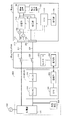
- FIG. 1 is a schematic configuration diagram of a power supply system according to an embodiment of the present invention.
- the power supply system includes a vehicle 10, a charging stand 200, a HEMS (Home Energy Management System) 300, a load device 400, and an external power source (hereinafter referred to as “external power source”). 500) and a switchboard 510.
- HEMS Home Energy Management System
- 500 external power source
- the vehicle 10 is a so-called plug-in type electric vehicle in which the in-vehicle power storage device can be charged by the external power source 500.
- the configuration of the electric vehicle is not particularly limited as long as it can travel with the electric power from the in-vehicle power storage device.
- Examples of the vehicle 10 include a hybrid vehicle, an electric vehicle, and a fuel cell vehicle.
- Vehicle 10 includes a power storage device 100, a power output device 135, an ECU (Electronic Control Unit) 130 for controlling the overall operation of the vehicle 10, a communication unit 140, and a storage unit 145 (see FIG. 2). .
- ECU Electronic Control Unit
- the power storage device 100 is a power storage element configured to be rechargeable, and typically, a secondary battery such as a lithium ion battery or a nickel metal hydride battery is applied. Alternatively, power storage device 100 may be configured by a power storage element other than a battery, such as an electric double layer capacitor.
- FIG. 1 shows a system configuration related to charge / discharge control of power storage device 100 in vehicle 10. Power storage device 100 is provided with a battery sensor (not shown) for detecting the voltage and current of power storage device 100.
- the monitoring unit 105 detects the state value of the power storage device 100 based on the output of the battery sensor provided in the power storage device 100. That is, the state value includes the voltage and / or current of power storage device 100. As described above, since a secondary battery is typically used as power storage device 100, the voltage and current of power storage device 100 are also referred to as battery voltage and battery current below. The battery voltage and battery current are also collectively referred to as “battery data”.
- the power output device 135 generates the driving force of the vehicle 10 using the electric power stored in the power storage device 100. Specifically, motive power output device 135 generates a driving force of vehicle 10 based on a driving command from ECU 130, and outputs the generated driving force to driving wheels (not shown) of vehicle 10.
- the drive command is a control command generated based on the requested vehicle driving force or vehicle braking force while the vehicle 10 is traveling.
- the ECU 130 determines the vehicle driving force and the vehicle necessary for the entire vehicle 10 according to the vehicle state of the vehicle 10 and the driver operation (accelerator pedal depression amount, shift lever position, brake pedal depression amount, etc.). Calculate the braking force. Then, ECU 130 generates a drive command for power output device 135 so as to realize the requested vehicle driving force or vehicle braking force.
- power output device 135 when power generation command is received from ECU 130, power output device 135 generates power to be supplied to load device 400 outside the vehicle, and outputs the generated power to power feeding unit 120.
- the power generation command is a control command for instructing generation of power to be supplied to the load device 400 in an emergency power generation mode described later.
- power output device 135 includes a power conversion unit (PCU) 150, motor generators 160 and 165, power transmission gear 175, engine 170, and drive wheels 180.
- PCU power conversion unit
- the PCU 150 is connected to the power storage device 100.
- the power storage device 100 supplies power for generating the driving force of the vehicle 10 to the PCU 150.
- Power storage device 100 stores the electric power generated by motor generators 160 and 165.
- PCU 150 includes a converter 152, inverters 154 and 156, and capacitors C1 and C2.
- Converter 152 performs voltage conversion between power lines PL1 and NL1 and power lines PL2 and NL1 based on control signal PWC from ECU 130.
- Inverters 154 and 156 are connected in parallel to power lines PL2 and NL1. Inverters 154 and 156 convert DC power supplied from converter 152 into AC power based on control signals PMI1 and PMI2 from ECU 130, and drive motor generators 160 and 165, respectively.
- Capacitor C1 is provided between power lines PL1 and NL1, and reduces voltage fluctuation between power lines PL1 and NL1.
- Motor generators 160 and 165 are AC rotating electric machines, for example, permanent magnet type synchronous motors including a rotor in which permanent magnets are embedded.
- the output torque of the motor generators 160 and 165 is transmitted to the drive wheels 180 via a power transmission gear 175 constituted by a speed reducer and a power split mechanism, thereby causing the vehicle 10 to travel.
- Motor generators 160 and 165 can generate electric power using the rotational force of drive wheels 180 during regenerative braking of vehicle 10. Then, the generated power is converted into charging power for power storage device 100 by PCU 150.
- motor generators 160 and 165 are also coupled to engine 170 via power transmission gear 175. Then, ECU 130 operates motor generators 160 and 165 and engine 170 in a coordinated manner to generate a necessary vehicle driving force. Further, motor generators 160 and 165 can generate electric power by rotation of engine 170, and can charge power storage device 100 using the generated electric power. In the present embodiment, motor generator 165 is used exclusively as an electric motor for driving drive wheels 180, and motor generator 160 is used exclusively as a generator driven by engine 170.
- FIG. 2 illustrates a configuration in which two motor generators are provided, but the number of motor generators is not limited to this, and a configuration in which one motor generator is provided or more than two motor generators are provided. It is good.
- vehicle 10 will be described as an example of a hybrid vehicle as described above.
- the configuration of vehicle 10 may include power generated from a generator driven by engine 170, and / or
- the configuration is not limited as long as the vehicle can supply power to the load device outside the vehicle using the power from power storage device 100. That is, in addition to the hybrid vehicle that generates vehicle driving force by the engine and electric motor as shown in FIG. 2, the vehicle 10 is not equipped with a vehicle that does not generate vehicle driving force but is provided with a generator that generates electric power by the engine. Includes electric vehicles and fuel cell vehicles.
- Vehicle 10 further includes an inlet 112 provided in the body of vehicle 10, charging unit 110, and charging relay 116 as a configuration for charging power storage device 100 with electric power from external power supply 500.
- the external power supply 500 is typically constituted by a single-phase AC commercial power supply. However, the power of the external power supply may be supplied by the power generated by the solar cell panel installed on the roof of a house instead of or in addition to the commercial power supply.
- the charging connector 212 of the charging cable 214 is connected to the inlet 112. Then, electric power from the external power source 500 is transmitted to the vehicle 10 via the charging cable 214.
- the charging unit 110 is a device for receiving power from the external power source 500 and charging the power storage device 100. Charging unit 110 is provided between inlet 112 and power storage device 100. Charging unit 110 converts AC power from external power supply 500 transmitted via inlet 112 via charging cable 214 into DC power for charging power storage device 100 in accordance with control command PWD 1 from ECU 130. To do.
- charging relay 116 that is inserted and connected to power lines PL3 and NL3 is provided. Charging relay 116 is turned on / off in response to relay control signal SE1 from ECU 130. Charging relay 116 is used as a representative example of an opening / closing device that can cut off a charging path of power storage device 100. That is, any type of switching device can be applied in place of the charging relay 116.
- ECU 130 generates control command PWD1 for controlling charging unit 110 when power storage device 100 is charged by external power supply 500, and outputs the generated control command PWD1 to charging unit 110.
- ECU 130 is connected to an external power source based on a pilot signal received from a charging circuit interrupting device (not shown) provided on the electric wire portion of charging cable 214 for switching between supply and interruption of power from external power source 500.
- 500 types are specified, and charging unit 110 is controlled in accordance with the specified type of external power supply 500.
- vehicle 10 further includes an inlet 122 provided in the body of vehicle 10, power supply unit 120, and power supply relay 126 as a configuration for supplying power to load device 400 (FIG. 1) outside the vehicle. .
- the power supply connector 222 of the power supply cable 224 is connected to the inlet 122. Then, the discharged power from power storage device 100 and / or the generated power from power output device 135 (motor generator 160) are transmitted to load device 400 via power supply cable 224. That is, power storage device 100 and / or power output device 135 (motor generator 160) corresponds to a “power generation unit” for generating power supplied to the outside of the vehicle.
- the power feeding unit 120 is a device for receiving the discharged power from the power storage device 100 and / or the generated power from the power output device 135 to feed power to the load device 400 outside the vehicle.
- power feeding unit 120 receives the discharged power from power storage device 100 and / or the generated power from power output device 135 (both DC power) transmitted via power lines PL3 and NL3. It converts into the alternating current power for driving the load apparatus 400 outside a vehicle.
- a power feeding relay 126 that is inserted and connected to the power lines PL3 and NL3 is provided.
- the power supply relay 126 is turned on / off in response to a relay control signal SE2 from the ECU 130.
- Power supply relay 126 is used as a representative example of an opening / closing device that can cut off a discharge path from power storage device 100 and / or power output device 135. In other words, any type of switching device can be applied in place of the power supply relay 126.
- ECU 130 includes a CPU (Central Processing Unit), a storage device, and an input / output buffer, both of which are not shown in FIGS. 1 and 2, and inputs signals from each sensor and outputs control signals to each device.
- the vehicle 10 and each device are controlled. These controls are not limited to processing by software, and can be processed by dedicated hardware (electronic circuit).
- ECU 130 calculates a state of charge (SOC) of power storage device 100 based on battery data (battery voltage and battery current) from monitoring unit 105.
- the SOC is a percentage (0 to 100%) of the current remaining capacity with respect to the full charge capacity.
- SOC of the electrical storage apparatus 100 since well-known arbitrary methods are applicable, detailed description is abbreviate
- ECU 130 generates and outputs a control command for controlling PCU 150, charging unit 110, charging relay 116, power feeding unit 120, and power feeding relay 126.
- ECU 130 communicates wirelessly or wiredly with communication units 240 and 350 provided in charging station 200 and HEMS 300 outside the vehicle via communication unit 140, respectively. Then, ECU 130 stores information transmitted from charging station 200 and communication units 240 and 350 of HEMS 300 in storage unit 145.
- power line communication can be used for communication among the vehicle 10, the charging station 200, and the HEMS 300.
- the communication units 140, 240, and 350 are configured by a PLC unit and transmit information via the power line.
- vehicle 10 is configured such that in-vehicle power storage device 100 can be charged by external power source 500 and power can be supplied from vehicle 10 to load device 400 outside the vehicle.
- charging of power storage device 100 by external power source 500 is also referred to as “external charging”, and electric power generated from power storage device 100 to the outside of the vehicle and / or power generated by power output device 135 (motor generator 160). Is also referred to as “external power supply”.
- a configuration for supplying electric power by electromagnetically coupling an external power source and a vehicle in a non-contact manner specifically, providing a primary coil on the external power source side
- charging stand 200 includes a charging cable 214, a charging connector 212, and a relay 210 for performing external charging.
- Charging stand 200 also includes a power feeding cable 224, a power feeding connector 222, and a relay 220 for performing external power feeding.
- Charging stand 200 further includes a controller 230 and a communication unit 240.
- Charging stand 200 is electrically connected to a distribution board 510 installed in a building such as house 600.
- the charging cable 214 has one end connected to the relay 210 and the other end connected to the charging connector 212. One end of the power supply cable 224 is connected to the relay 220 and the other end is connected to the power supply connector 222.
- the charging cable 214 and the power feeding cable 224 may be separable from the charging stand 200. Alternatively, the charging stand 200 and the vehicle 10 may be connected using a charging cable and a power feeding cable provided in the vehicle 10.
- the charging cable 214 and the charging connector 212 and the power feeding cable 224 and the power feeding connector 222 are separately provided. However, one cable and one connector are used by switching between charging and power feeding. It is good. In this case, also on the vehicle 10 side, the inlets 112 and 122 are combined into one inlet that can be switched between charging and power feeding.
- the charging connector 212 is connected to the inlet 112 of the vehicle 10 and power is supplied from the external power source 500 to the vehicle 10 via the switchboard 510 of the house 600 with the relay 210 closed.
- the power supply connector 222 connected to the inlet 122 of the vehicle 10 and the relay 220 closed.
- the opening / closing operation of the relays 210 and 220 is controlled by the controller 230.
- the controller 230 is constituted by a CPU, for example.
- the controller 230 is configured to be able to communicate with the ECU 130 of the vehicle 10 by wireless or wired via the communication units 240 and 140. Further, the controller 230 is configured to be able to communicate with the CPU 340 of the HEMS 300 via the communication units 240 and 350 by wireless or wired.
- the controller 230 transmits a signal indicating the state of the relays 210 and 220 (open state or closed state) to the CPU 340 of the HEMS 300 and the ECU 130 of the vehicle 10. That is, the controller 230 transmits a signal indicating whether external charging or external power feeding has been selected to the CPU 340 and the ECU 130.
- the HEMS 300 is installed inside or outside the house 600.
- the HEMS 300 is electrically connected to the switchboard 510 and the charging stand 200.
- the HEMS 300 includes a DC / AC converter 310, an AC / DC converter 320, a CPU 340, and a communication unit 350.
- AC / DC converter 320 converts AC power supplied from charging station 200 into DC power.
- the DC / AC converter 310 converts the DC power converted by the AC / DC converter 320 into AC power.
- AC / DC converter 320 and DC / AC converter 310 are controlled by a control signal generated by CPU 340 based on a signal transmitted from communication unit 240 of charging stand 200 indicating which of external charging and external power feeding has been selected.
- the load device 400 is an arbitrary electrical device that operates by receiving power from the external power supply 500 via the switchboard 510.
- Load device 400 may be house 600, for example, or may be an individual appliance.
- the load device 400 may be a vehicle other than the vehicle 10.
- the vehicle 10 when the external power supply 500 fails, the power supply to the load device 400 is cut off.
- the vehicle 10 is regarded as a power supply source instead of the external power supply 500, and power is supplied from the vehicle 10 to the load device 400.
- a mode in which external power feeding is performed using the vehicle 10 as an emergency power source for the external power source 500 is referred to as an “emergency power generation mode”.
- a mode in which external power supply and external charging are performed when external power supply 500 is normal is referred to as a “normal mode”.
- the specification of the load device 400 (hereinafter also referred to as “load specification”) is a specification related to the power supplied to the load device 400, and includes the frequency and voltage of the external power supply 500.
- the frequency of the commercial power supply is typically 50 kHz or 60 kHz.
- the commercial AC voltage generated by the commercial grid power supply is 100V or 200V.
- the ECU 130 of the vehicle 10 can acquire the load specification by communicating with the HEMS 300 and the charging station 200 via the communication units 140, 240, and 350. And the vehicle 10 can generate
- FIG. 1 the ECU 130 of the vehicle 10 can acquire the load specification by communicating with the HEMS 300 and the charging station 200 via the communication units 140, 240, and 350.
- the vehicle 10 can generate
- FIG. 3 is a diagram showing a power supply system when the external power supply 500 is out of power.
- the frequency and voltage of external power supply 500 that are load specifications are set as power generation parameters by CPU 340 of HEMS 300.
- the power generation parameter is transmitted to the ECU 130 of the vehicle 10 via the communication units 350, 240, and 140, the power generation parameter is used by the ECU 130 for a power feeding operation in the vehicle 10.
- the ECU 130 of the vehicle 10 converts the discharged power from the power storage device 100 into AC power defined by the power generation parameters and supplies the AC power to the outside of the vehicle.
- the ECU 130 converts the DC power generated by the power output device 135 into AC power defined by the power generation parameters and supplies the AC power to the outside of the vehicle.
- the ECU 130 turns the normal mode off while turning the emergency power generation mode on.
- emergency power generation mode is turned on, ECU 130 converts DC power from power storage device 100 and / or power output device 135 into AC power suitable for driving load device 400 outside the vehicle.
- the power conversion operation in the power feeding unit 120 is controlled.
- ECU 130 cannot control power feeding unit 120 because it cannot obtain power generation parameters for defining the frequency and voltage of AC power.
- the specification (load specification) of the power supplied to the load device 400 when the external power supply 500 is normal, that is, in the normal mode, is acquired in advance.
- it is stored in the storage unit 145 as a power generation parameter.
- the vehicle 10 reads the power generation parameters stored in the storage unit 145, and controls the power conversion operation of the power feeding unit 120 using the read power generation parameters. .
- FIG. 4 is a diagram for explaining the operation in the normal mode of the power supply system according to the embodiment of the present invention.
- the frequency and voltage of external power supply 500 which are load specifications, are set as power generation parameters by CPU 340 of HEMS 300.
- the CPU 340 causes the communication unit 350 to The power generation parameters are transmitted to the vehicle 10 via the communication unit 240 of the charging stand 200.
- the CPU 340 transmits the power generation parameter in association with the identification code ID of the charging station 200.
- the ECU 130 stores the received power generation parameter in the storage unit 145 in association with the ID of the charging station 200.
- the ECU 130 of the vehicle 10 reads the power generation parameters from the storage unit 145 using the ID of the charging station 200 as a clue. Then, ECU 130 controls the power conversion operation in power feeding unit 120 using the read power generation parameter. Thereby, from the vehicle 10, appropriate AC power corresponding to the specification of the power supplied to the load device 400 is output and supplied to the load device 400 through the charging stand 200 and the HEMS 330.
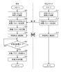
- FIG. 5 is a flowchart for explaining the operation of the vehicle and the charging station in the power supply system according to the embodiment of the present invention.
- charging station 200 when charging station 200 and vehicle 10 are connected in steps S01 and S11, charging station 200 communicates power generation parameters (load specifications) set by CPU 340 of HEMS 300 in step S12. It transmits to the vehicle 10 via the part 240.
- power generation parameters load specifications
- the ECU 130 stores the received power generation parameter in the storage unit 145 in association with the ID of the charging station 200 in step S03. .
- step S05 the ECU 130 determines whether or not the emergency power generation mode is turned on in step S05. If the emergency power generation mode is not turned on (NO in step S05), the process returns to step S05.
- the emergency power generation mode is turned on (YES in step S05)
- the ECU 130 reads out the power generation parameters stored in the storage unit 145 using the ID of the charging station 200 as a clue in step S06.
- step S07 ECU 130 uses the read power generation parameter to control the power conversion operation of power feeding unit 120, thereby generating AC power to be supplied from vehicle 10 to load device 400.
- AC power generated by the vehicle 10 is supplied to the load device 400 via the charging station 200 and the HEMS 300.
- load device 400 is driven by receiving power supplied from vehicle 10 instead of external power supply 500.
- power storage device 100 and power output device 135 correspond to “power generation unit”
- power supply unit 120 corresponds to “power supply unit”
- ECU 130 corresponds to “control device”.
- the HEMS 300 and the charging stand 200 correspond to a “power supply device”.
- the specification (load specification) related to the power supplied to the load device outside the vehicle is stored in the storage unit of the vehicle when the external power supply is normal.
- the specification load specification
- emergency power generation during a power failure of the external power supply can be reliably executed, and the load device can be driven stably.
- the charging unit 110 and the power feeding unit 120 have been described as separate devices. However, a configuration in which one power conversion unit capable of bidirectional power conversion for charging and power feeding may be provided.
- FIG. 1 illustrates a configuration in which the communication unit is provided in each of the charging stand 200 and the HEMS 300, but a configuration in which a communication unit for communicating with the vehicle 10 is provided in either the charging stand 200 or the HEMS 300 may be employed. .
- FIG. 6 is a diagram for explaining the operation in the normal mode of the power supply system according to the modification of the embodiment of the present invention.
- the power supply system according to the present modification is different from the power supply system shown in FIG. 1 in that vehicle 10 further includes a frequency sensor 190 and a voltage sensor 192.
- the frequency sensor 190 is inserted and connected to a power line connecting the inlet 112 and the charging unit 110.
- the frequency sensor 190 detects the frequency f of AC power supplied from the charging cable 214 to the power line through the inlet 112, and outputs the detected value to the ECU 130.
- Voltage sensor 192 is connected to the power line, detects voltage VAC of AC power supplied to the power line, and outputs the detected value to ECU 130.
- ECU 130 acquires the detection values of frequency sensor 190 and voltage sensor 192 during execution of external charging when external charging is started by connecting charging station 200 and vehicle 10 via charging cable 214. Further, ECU 130 obtains a supply current (corresponding to a charging current of power storage device 100) IAC flowing through charging unit 110. Then, ECU 130 calculates the frequency and voltage of external power supply 500, which is a load specification, based on the acquired frequency f of supply power, voltage VAC, and supply current IAC.
- ECU 130 sets frequency f detected by frequency sensor 190 as frequency f of external power supply 500.
- ECU 130 calculates voltage V of external power supply 500 using equation (1) using voltage VAC detected by voltage sensor 192, supply current IAC, and wiring resistance R between vehicle 10 and switchboard 510. To do.
- V VAC + IAC ⁇ R (1)
- the wiring resistance R in the above formula (1) is calculated in advance based on the wire length of the power line (including the charging cable 214) disposed between the vehicle 10 and the switchboard 510.
- the ECU 130 stores the calculated frequency f and voltage V of the external power supply 500 in the storage unit 145 as power generation parameters.
- the ECU 130 reads the power generation parameter from the storage unit 145, and controls the power conversion operation in the power feeding unit 120 using the read power generation parameter.
- appropriate AC power corresponding to the specifications of the load device 400 is output from the vehicle 10 and supplied to the load device 400 through the charging stand 200 and the HEMS 300.
- FIG. 7 is a flowchart for explaining the operation of the vehicle and the charging station in the power supply system according to the modification of the embodiment of the present invention.
- charging station 200 when charging station 200 and vehicle 10 are connected via charging cable 214 in steps S21 and S31, charging station 200 supplies electric power from external power source 500 to vehicle 10 in step S32. To supply.
- charging unit 110 when charging unit 110 receives power from external power supply 500 in step S ⁇ b> 22, charging unit 110 converts power supplied from external power supply 500 into power suitable for charging power storage device 100.
- ECU 130 of vehicle 10 acquires frequency f and voltage VAC of power supplied from external power supply 500 from frequency sensor 190 and voltage sensor 192, respectively, in step S23. Further, ECU 130 acquires charging current IAC. Then, ECU 130 calculates frequency f and voltage V (load specification) of external power supply 500 in step S24. When ECU 130 sets the calculated frequency f and voltage V of external power supply 500 as the power generation parameters, ECU 130 stores the power generation parameters in storage unit 145 in step S25.
- step S27 the ECU 130 determines whether or not the emergency power generation mode is turned on in step S27. If the emergency power generation mode is not turned on (NO in step S27), the process returns to step S27.
- the emergency power generation mode is turned on (YES in step S27)
- the ECU 130 reads out the power generation parameters stored in the storage unit 145 using the ID of the charging station 200 as a clue in step S28.
- step S29 ECU 130 controls the power conversion operation of power feeding unit 120 using the read power generation parameter to generate AC power to be supplied from vehicle 10 to load device 400.
- AC power generated by the vehicle 10 is supplied to the load device 400 via the charging station 200 and the HEMS 300.
- the load device 400 is driven by receiving electric power supplied from the vehicle 10.
- the ECU of the vehicle calculates the load specification based on the power supplied from the external power source, and the calculated load specification is generated. It is stored as a parameter in the storage unit inside the vehicle. As a result, the vehicle can acquire the load specification even when the vehicle does not have a communication function with the charging stand or the HEMS. Therefore, after the power failure of the external power supply, the vehicle uses the specification stored in the storage unit according to the load specification. The appropriate electric power can be supplied from the vehicle. As a result, it is possible to reliably execute emergency power generation at the time of a power failure of the external power source and stably drive the load device.
- the present invention can be applied to a power supply system that supplies electric power from a vehicle to a load outside the vehicle.
- 10 vehicle 100 power storage device, 105 monitoring unit, 110 charging unit, 112, 122 inlet, 116 charging relay, 120 feeding unit, 126 feeding relay, 135 power output device, 140, 240, 350 communication unit, 145 storage unit, 152 Converter, 154, 156 inverter, 160, 165 motor generator, 170 engine, 175 power transmission gear, 180 drive wheel, 190 frequency sensor, 192 voltage sensor, 200 charging stand, 210, 220 relay, 212 charging connector, 214 charging cable, 222 power connector, 224 power cable, 230 controller, 300 HEMS, 310 AC / DC converter, 320 DC / AC converter, 400 load device, 500 Parts supply, 510 switchboard, 600 houses.
Abstract
Description
図1を参照して、電力供給システムは、車両10と、充電スタンド200と、HEMS(Home Energy Management System)300と、負荷装置400と、車両10の外部の電源(以下、「外部電源」とも称する)500と、配電盤510とを備える。 FIG. 1 is a schematic configuration diagram of a power supply system according to an embodiment of the present invention.
Referring to FIG. 1, the power supply system includes a
図2を参照して、動力出力装置135は、電力変換ユニット(PCU:Power Control Unit)150と、モータジェネレータ160,165と、動力伝達ギヤ175と、エンジン170と、駆動輪180とを含む。 With reference to FIG. 2, the configuration of vehicle 10 (FIG. 1) will be further described.
Referring to FIG. 2,
図3を参照して、負荷仕様である外部電源500の周波数および電圧は、HEMS300のCPU340によって発電パラメータに設定される。発電パラメータは、通信部350,240,140を介して車両10のECU130に送信されると、ECU130によって車両10における給電動作に用いられる。具体的には、車両10のECU130は、蓄電装置100からの放電電力を、発電パラメータにより規定される交流電力に変換して車両外部へ供給する。また、ECU130は、動力出力装置135により発電された直流電力を、発電パラメータにより規定される交流電力に変換して車両外部へ供給する。 FIG. 3 is a diagram showing a power supply system when the
Referring to FIG. 3, the frequency and voltage of
上記の実施の形態では、車両10の記憶部145に負荷仕様を格納するための構成として、外部電源500の正常時に充電スタンド200から車両10に対して負荷仕様を送信する構成について説明した。 [Modification]
In the above embodiment, the configuration for transmitting the load specification from the charging stand 200 to the
なお、上記式(1)における配線抵抗Rは、車両10および配電盤510間に配設される電力線(充電ケーブル214を含む)の電線長に基づいて予め算出されている。 V = VAC + IAC × R (1)
In addition, the wiring resistance R in the above formula (1) is calculated in advance based on the wire length of the power line (including the charging cable 214) disposed between the
ステップS26,S34により外部電源500の停電が発生すると、充電スタンド200の通信部240の動作が停止することによって、充電スタンド200と車両10との間における通信が遮断される。[Correction 27.07.2012 under Rule 91]
When a power failure occurs in the
車両10においては、外部電源500の停電が発生すると、ステップS27により、ECU130は、非常用発電モードがオンされたか否かを判定する。非常用発電モードがオンされていない場合(ステップS27のNO判定時)には、処理はステップS27に戻される。そして、非常用発電モードがオンされると(ステップS27のYES判定時)、ECU130は、ステップS28により、充電スタンド200のIDを手がかりに、記憶部145に蓄積されている発電パラメータを読み出す。そして、ECU130は、ステップS29により、読み出した発電パラメータを用いて給電部120の電力変換動作を制御することにより、車両10から負荷装置400に供給するための交流電力を発生する。[Correction 27.07.2012 under Rule 91]
In the
Claims (8)
- 車両(10)と、
前記車両(10)からの電力を前記車両(10)の外部の負荷(400)に供給するための給電装置(200,300)とを備え、
前記負荷(400)は、外部電源(500)から電力の供給を受ける一方で、前記外部電源(500)の停電時には前記車両(10)からの電力を受けて駆動するように構成され、
前記車両(10)は、
発電部(100,135)と、
前記発電部(100,135)からの電力を前記給電装置(200,300)へ供給するための給電部(120)と、
前記外部電源(500)から前記負荷(400)に供給される電力に関する仕様を格納するための記憶部(145)と、
前記外部電源(500)の正常時に前記供給電力の仕様を前記記憶部(145)に格納するとともに、前記外部電源(500)の停電時、前記記憶部(145)に格納された前記供給電力の仕様に基づいて、前記発電部(100,135)からの電力を前記負荷(400)の駆動電力に変換するように、前記給電部(120)を制御する制御装置(130)とを含む、電力供給システム。 A vehicle (10);
A power supply device (200, 300) for supplying electric power from the vehicle (10) to a load (400) outside the vehicle (10),
The load (400) is configured to receive power from the external power source (500) and to drive by receiving power from the vehicle (10) during a power failure of the external power source (500).
The vehicle (10)
A power generation unit (100, 135);
A power feeding unit (120) for supplying power from the power generation unit (100, 135) to the power feeding device (200, 300);
A storage unit (145) for storing specifications relating to power supplied from the external power source (500) to the load (400);
The specification of the supplied power is stored in the storage unit (145) when the external power source (500) is normal, and the supply power stored in the storage unit (145) is stored when the external power source (500) is out of power. And a control device (130) for controlling the power feeding unit (120) so as to convert power from the power generation unit (100, 135) into driving power for the load (400) based on specifications. Supply system. - 前記車両(10)は、前記給電装置(200,300)との間で通信を行なうための通信部(140)をさらに含み、
前記制御装置(130)は、前記外部電源(500)の正常時、前記通信部(140)により前記給電装置(200,300)から前記供給電力の仕様を受信して前記記憶部(145)に格納する、請求項1に記載の電力供給システム。 The vehicle (10) further includes a communication unit (140) for communicating with the power feeding device (200, 300),
When the external power source (500) is normal, the control device (130) receives the specification of the supplied power from the power supply device (200, 300) by the communication unit (140) and stores it in the storage unit (145). The power supply system according to claim 1, wherein the power supply system is stored. - 前記車両(10)は、前記外部電源(500)の正常時には前記外部電源(500)から電力の供給を受けるように構成され、
前記制御装置(130)は、前記外部電源(500)から供給される電力に基づいて前記供給電力の仕様を算出して前記記憶部(145)に格納する、請求項1に記載の電力供給システム。 The vehicle (10) is configured to receive power from the external power source (500) when the external power source (500) is normal.
The power supply system according to claim 1, wherein the control device (130) calculates a specification of the supplied power based on the power supplied from the external power supply (500) and stores the specification in the storage unit (145). . - 前記発電部(100,135)は、再充電可能な蓄電装置(100)を含み、
前記給電部(120)は、前記蓄電装置(100)から放電される電力を前記負荷(400)の駆動電力に変換する、請求項1から3のいずれか1項に記載の電力供給システム。 The power generation unit (100, 135) includes a rechargeable power storage device (100),
The power supply system according to any one of claims 1 to 3, wherein the power feeding unit (120) converts electric power discharged from the power storage device (100) into driving electric power for the load (400). - 前記車両(10)は、駆動力源としての内燃機関(170)をさらに含み、
前記発電部(100,135)は、
再充電可能な蓄電装置(100)と、
前記内燃機関(170)の出力を用いて発電するように構成された発電機(160)とを含み、
前記給電部(120)は、前記蓄電装置(100)から放電される電力および前記発電機(160)によって発電された電力の少なくとも一方を前記負荷(400)の駆動電力に変換する、請求項1から3のいずれか1項に記載の電力供給システム。 The vehicle (10) further includes an internal combustion engine (170) as a driving force source,
The power generation unit (100, 135)
A rechargeable power storage device (100);
A generator (160) configured to generate electricity using the output of the internal combustion engine (170),
The power feeding unit (120) converts at least one of electric power discharged from the power storage device (100) and electric power generated by the generator (160) into driving electric power for the load (400). 4. The power supply system according to any one of items 1 to 3. - 車両外部に設けられた負荷(400)へ電力を供給可能な車両(10)であって、
前記負荷(400)は、外部電源(500)から電力の供給を受ける一方で、前記外部電源(500)の停電時には前記車両(10)からの電力を受けて駆動するように構成され、
発電部(100,135)と、
前記発電部(100,135)からの電力を前記負荷(400)へ供給するための給電部(120)と、
前記外部電源(500)から前記負荷(400)に供給される電力に関する仕様を格納するための記憶部(145)と、
前記外部電源(500)の正常時に前記供給電力の仕様を前記記憶部(145)に格納するとともに、前記外部電源(500)の停電時、前記記憶部(145)に格納された前記供給電力の仕様に基づいて、前記発電部(100,135)からの電力を前記負荷(400)の駆動電力に変換するように、前記給電部(120)を制御する制御装置(130)とを備える、車両。 A vehicle (10) capable of supplying electric power to a load (400) provided outside the vehicle,
The load (400) is configured to receive power from the external power source (500) and to drive by receiving power from the vehicle (10) during a power failure of the external power source (500).
A power generation unit (100, 135);
A power feeding unit (120) for supplying power from the power generation unit (100, 135) to the load (400);
A storage unit (145) for storing specifications relating to power supplied from the external power source (500) to the load (400);
The specification of the supplied power is stored in the storage unit (145) when the external power source (500) is normal, and the supply power stored in the storage unit (145) is stored when the external power source (500) is out of power. A control device (130) that controls the power supply unit (120) so as to convert electric power from the power generation unit (100, 135) into driving power of the load (400) based on specifications; . - 前記車両(10)の外部と通信を行なうための通信部(140)をさらに備え、
前記制御装置(130)は、前記外部電源(500)の正常時、前記通信部(140)により前記車両(10)の外部から前記供給電力の仕様を受信して前記記憶部(145)に格納する、請求項6に記載の車両。 A communication unit (140) for communicating with the outside of the vehicle (10);
When the external power source (500) is normal, the control device (130) receives the specification of the supplied power from the outside of the vehicle (10) by the communication unit (140) and stores it in the storage unit (145). The vehicle according to claim 6. - 前記車両(10)は、前記外部電源(500)の正常時には前記外部電源(500)からの電力の供給を受けるように構成され、
前記制御装置(130)は、前記外部電源(500)から供給される電力に基づいて前記供給電力の仕様を算出して前記記憶部(145)に格納する、請求項6に記載の車両。 The vehicle (10) is configured to receive power from the external power source (500) when the external power source (500) is normal.
The vehicle according to claim 6, wherein the control device (130) calculates a specification of the supplied power based on the power supplied from the external power source (500) and stores the specification in the storage unit (145).
Priority Applications (5)
| Application Number | Priority Date | Filing Date | Title |
|---|---|---|---|
| US13/634,397 US20140225441A1 (en) | 2011-10-27 | 2011-10-27 | Power supply system and vehicle |
| JP2012541668A JP5673687B2 (en) | 2011-10-27 | 2011-10-27 | Power supply system and vehicle |
| EP11861330.6A EP2773016A4 (en) | 2011-10-27 | 2011-10-27 | Power supply system and vehicle |
| CN201180017090XA CN103190057A (en) | 2011-10-27 | 2011-10-27 | Power supply system and vehicle |
| PCT/JP2011/074807 WO2013061443A1 (en) | 2011-10-27 | 2011-10-27 | Power supply system and vehicle |
Applications Claiming Priority (1)
| Application Number | Priority Date | Filing Date | Title |
|---|---|---|---|
| PCT/JP2011/074807 WO2013061443A1 (en) | 2011-10-27 | 2011-10-27 | Power supply system and vehicle |
Publications (1)
| Publication Number | Publication Date |
|---|---|
| WO2013061443A1 true WO2013061443A1 (en) | 2013-05-02 |
Family
ID=48167309
Family Applications (1)
| Application Number | Title | Priority Date | Filing Date |
|---|---|---|---|
| PCT/JP2011/074807 WO2013061443A1 (en) | 2011-10-27 | 2011-10-27 | Power supply system and vehicle |
Country Status (5)
| Country | Link |
|---|---|
| US (1) | US20140225441A1 (en) |
| EP (1) | EP2773016A4 (en) |
| JP (1) | JP5673687B2 (en) |
| CN (1) | CN103190057A (en) |
| WO (1) | WO2013061443A1 (en) |
Cited By (4)
| Publication number | Priority date | Publication date | Assignee | Title |
|---|---|---|---|---|
| JP2013094026A (en) * | 2011-10-27 | 2013-05-16 | Toyota Motor Corp | Power supply system and vehicle |
| JP2015095955A (en) * | 2013-11-12 | 2015-05-18 | ニチコン株式会社 | Power conversion device to be used while connected to electric motor car |
| JP2015154629A (en) * | 2014-02-17 | 2015-08-24 | 田淵電機株式会社 | Universal power storage device and control method therefor |
| JP2019071721A (en) * | 2017-10-10 | 2019-05-09 | ニチコン株式会社 | Power supply system |
Families Citing this family (10)
| Publication number | Priority date | Publication date | Assignee | Title |
|---|---|---|---|---|
| JP5345263B1 (en) * | 2012-05-18 | 2013-11-20 | 三菱電機株式会社 | Inverter device |
| US9975437B2 (en) * | 2015-12-21 | 2018-05-22 | Delphi Technologies Inc. | Conductor winding tool and battery charger having the same |
| CN105680509B (en) * | 2016-01-29 | 2018-12-14 | 易事特集团股份有限公司 | Charging pile with power down process function |
| JP6654594B2 (en) * | 2017-03-16 | 2020-02-26 | ヤンマー株式会社 | Engine system |
| US11260810B2 (en) * | 2017-06-12 | 2022-03-01 | Autonetworks Technologies, Ltd. | Distributor and on-board system |
| JP6897371B2 (en) * | 2017-07-03 | 2021-06-30 | トヨタ自動車株式会社 | Vehicle and power transmission system |
| US10732699B2 (en) * | 2018-02-23 | 2020-08-04 | Intel Corporation | Redundancy in distribution of voltage-frequency scaling parameters |
| WO2019225168A1 (en) * | 2018-05-22 | 2019-11-28 | 本田技研工業株式会社 | Electric-powered vehicle and method for controlling electric-powered vehicle |
| JP7147457B2 (en) * | 2018-10-18 | 2022-10-05 | トヨタ自動車株式会社 | Vehicle and charging system |
| DE102020106343A1 (en) | 2020-03-09 | 2021-09-09 | Audi Aktiengesellschaft | A method for operating an arrangement comprising a charging station and a motor vehicle, an arrangement comprising a charging station and a motor vehicle, and a method for operating a motor vehicle and a method for operating a charging station |
Citations (4)
| Publication number | Priority date | Publication date | Assignee | Title |
|---|---|---|---|---|
| JP2001008380A (en) * | 1999-06-17 | 2001-01-12 | Nissan Motor Co Ltd | Power management system |
| JP2006166534A (en) * | 2004-12-03 | 2006-06-22 | Densei Lambda Kk | Power supply |
| WO2010010754A1 (en) * | 2008-07-25 | 2010-01-28 | トヨタ自動車株式会社 | Charge/discharge system and electric vehicle |
| US20100164287A1 (en) * | 2008-12-25 | 2010-07-01 | Honda Motor Co., Ltd. | Electric power supply system between vehicle and house |
Family Cites Families (14)
| Publication number | Priority date | Publication date | Assignee | Title |
|---|---|---|---|---|
| JPH11178234A (en) * | 1997-12-10 | 1999-07-02 | Nissan Motor Co Ltd | Household power supply system using electric vehicle |
| US7256516B2 (en) * | 2000-06-14 | 2007-08-14 | Aerovironment Inc. | Battery charging system and method |
| JP4266358B2 (en) * | 2004-04-12 | 2009-05-20 | 三菱電機株式会社 | In-vehicle electronic control unit |
| JP4578952B2 (en) * | 2004-11-29 | 2010-11-10 | トヨタ自動車株式会社 | Power supply device at power failure and wiring structure of house |
| JP2006154637A (en) * | 2004-12-01 | 2006-06-15 | Nippon Synthetic Chem Ind Co Ltd:The | Photosensitive resin composition, photoresist film using same, and resist pattern forming method |
| JP4208016B2 (en) * | 2007-02-13 | 2009-01-14 | トヨタ自動車株式会社 | HYBRID VEHICLE, HYBRID VEHICLE CONTROL METHOD, HYBRID VEHICLE CONTROL PROGRAM, AND RECORDING MEDIUM CONTAINING THE PROGRAM |
| JP2008289273A (en) * | 2007-05-17 | 2008-11-27 | Toyota Motor Corp | Power supply system, and vehicle |
| JP2008302771A (en) * | 2007-06-06 | 2008-12-18 | Toyota Motor Corp | Information system using vehicle, charging device, and vehicle |
| FR2919768B1 (en) * | 2007-08-03 | 2016-02-12 | Alstom Transport Sa | METHOD OF SUPPLYING AUXILIARY EMERGENCY LOADS, AUXILIARY CONVERTER AND RAILWAY VEHICLE FOR THIS METHOD. |
| JP4453741B2 (en) * | 2007-10-25 | 2010-04-21 | トヨタ自動車株式会社 | Electric vehicle and vehicle power supply device |
| JP4191781B1 (en) * | 2007-12-17 | 2008-12-03 | 和征 榊原 | Battery pack |
| JP2013045586A (en) * | 2011-08-23 | 2013-03-04 | Hitachi Koki Co Ltd | Battery adapter and power supply device with the same |
| JP2013046478A (en) * | 2011-08-23 | 2013-03-04 | Hitachi Koki Co Ltd | Battery adapter and power supply device with the same |
| JP5630419B2 (en) * | 2011-10-27 | 2014-11-26 | トヨタ自動車株式会社 | Power supply system and vehicle |
-
2011
- 2011-10-27 US US13/634,397 patent/US20140225441A1/en not_active Abandoned
- 2011-10-27 EP EP11861330.6A patent/EP2773016A4/en not_active Withdrawn
- 2011-10-27 CN CN201180017090XA patent/CN103190057A/en active Pending
- 2011-10-27 JP JP2012541668A patent/JP5673687B2/en not_active Expired - Fee Related
- 2011-10-27 WO PCT/JP2011/074807 patent/WO2013061443A1/en active Application Filing
Patent Citations (5)
| Publication number | Priority date | Publication date | Assignee | Title |
|---|---|---|---|---|
| JP2001008380A (en) * | 1999-06-17 | 2001-01-12 | Nissan Motor Co Ltd | Power management system |
| JP2006166534A (en) * | 2004-12-03 | 2006-06-22 | Densei Lambda Kk | Power supply |
| WO2010010754A1 (en) * | 2008-07-25 | 2010-01-28 | トヨタ自動車株式会社 | Charge/discharge system and electric vehicle |
| US20100164287A1 (en) * | 2008-12-25 | 2010-07-01 | Honda Motor Co., Ltd. | Electric power supply system between vehicle and house |
| JP2010154637A (en) | 2008-12-25 | 2010-07-08 | Honda Motor Co Ltd | Electric power supply system between vehicle and house |
Non-Patent Citations (1)
| Title |
|---|
| See also references of EP2773016A4 |
Cited By (4)
| Publication number | Priority date | Publication date | Assignee | Title |
|---|---|---|---|---|
| JP2013094026A (en) * | 2011-10-27 | 2013-05-16 | Toyota Motor Corp | Power supply system and vehicle |
| JP2015095955A (en) * | 2013-11-12 | 2015-05-18 | ニチコン株式会社 | Power conversion device to be used while connected to electric motor car |
| JP2015154629A (en) * | 2014-02-17 | 2015-08-24 | 田淵電機株式会社 | Universal power storage device and control method therefor |
| JP2019071721A (en) * | 2017-10-10 | 2019-05-09 | ニチコン株式会社 | Power supply system |
Also Published As
| Publication number | Publication date |
|---|---|
| JP5673687B2 (en) | 2015-02-18 |
| CN103190057A (en) | 2013-07-03 |
| JPWO2013061443A1 (en) | 2015-04-02 |
| US20140225441A1 (en) | 2014-08-14 |
| EP2773016A1 (en) | 2014-09-03 |
| EP2773016A4 (en) | 2015-09-16 |
Similar Documents
| Publication | Publication Date | Title |
|---|---|---|
| JP5673687B2 (en) | Power supply system and vehicle | |
| JP5679071B2 (en) | Power supply system and power supply device | |
| JP5630419B2 (en) | Power supply system and vehicle | |
| US9216655B2 (en) | Vehicle and power supply system | |
| US9434257B2 (en) | Power supply connector, vehicle and control method for vehicle | |
| JP6156484B2 (en) | vehicle | |
| EP3415359B1 (en) | Electrical powered vehicle and power feeding device for vehicle | |
| JP5343981B2 (en) | Vehicle charging system | |
| JP6044460B2 (en) | Vehicle power supply | |
| JP5682537B2 (en) | Power supply system and power supply device | |
| WO2012049559A2 (en) | Electromotive vehicle | |
| JP2011004448A (en) | Charging cable, electronic control device, and failure detection method of charging cable | |
| JP2012249384A (en) | Vehicle | |
| JP2015077856A (en) | Hybrid-vehicular control apparatus | |
| WO2013042244A1 (en) | Vehicle power supply system | |
| JP5625715B2 (en) | Vehicle control apparatus and control method | |
| WO2012164681A1 (en) | Vehicle and method for controlling vehicle | |
| WO2013121472A2 (en) | Feed cable, power supply system and electric-powered vehicle |
Legal Events
| Date | Code | Title | Description |
|---|---|---|---|
| ENP | Entry into the national phase |
Ref document number: 2012541668 Country of ref document: JP Kind code of ref document: A |
|
| WWE | Wipo information: entry into national phase |
Ref document number: 13634397 Country of ref document: US |
|
| REEP | Request for entry into the european phase |
Ref document number: 2011861330 Country of ref document: EP |
|
| WWE | Wipo information: entry into national phase |
Ref document number: 2011861330 Country of ref document: EP |
|
| 121 | Ep: the epo has been informed by wipo that ep was designated in this application |
Ref document number: 11861330 Country of ref document: EP Kind code of ref document: A1 |
|
| NENP | Non-entry into the national phase |
Ref country code: DE |