WO2013051645A1 - 電子機器及び移動速度算出システム - Google Patents
電子機器及び移動速度算出システム Download PDFInfo
- Publication number
- WO2013051645A1 WO2013051645A1 PCT/JP2012/075776 JP2012075776W WO2013051645A1 WO 2013051645 A1 WO2013051645 A1 WO 2013051645A1 JP 2012075776 W JP2012075776 W JP 2012075776W WO 2013051645 A1 WO2013051645 A1 WO 2013051645A1
- Authority
- WO
- WIPO (PCT)
- Prior art keywords
- movement amount
- electronic device
- amount vector
- calculation unit
- reliability score
- Prior art date
- Legal status (The legal status is an assumption and is not a legal conclusion. Google has not performed a legal analysis and makes no representation as to the accuracy of the status listed.)
- Ceased
Links
Images


Classifications
-
- G—PHYSICS
- G01—MEASURING; TESTING
- G01P—MEASURING LINEAR OR ANGULAR SPEED, ACCELERATION, DECELERATION, OR SHOCK; INDICATING PRESENCE, ABSENCE, OR DIRECTION, OF MOVEMENT
- G01P3/00—Measuring linear or angular speed; Measuring differences of linear or angular speeds
- G01P3/36—Devices characterised by the use of optical means, e.g. using infrared, visible, or ultraviolet light
- G01P3/38—Devices characterised by the use of optical means, e.g. using infrared, visible, or ultraviolet light using photographic means
-
- G—PHYSICS
- G01—MEASURING; TESTING
- G01P—MEASURING LINEAR OR ANGULAR SPEED, ACCELERATION, DECELERATION, OR SHOCK; INDICATING PRESENCE, ABSENCE, OR DIRECTION, OF MOVEMENT
- G01P7/00—Measuring speed by integrating acceleration
Definitions
- the present invention relates to an electronic device and a moving speed calculation system.
- This application claims priority based on Japanese Patent Application No. 2011-220834 for which it applied on October 5, 2011, and uses the content here.
- Patent Document 1 an electronic device including an acceleration sensor is known (see, for example, Patent Document 1).
- An object of an aspect of the present invention is to provide a technique for accurately calculating a moving speed of a housing in a space.
- An electronic device includes a camera, an acceleration sensor that detects acceleration applied to the housing, a captured image captured by the camera, and an acceleration detected by the acceleration sensor.
- a moving speed calculating unit that calculates a moving speed of the body.
- a moving speed calculation system includes a first electronic device and a second electronic device, and the second electronic device using the first electronic device and the second electronic device.
- a moving speed calculation system for calculating a moving speed of a device wherein the first electronic device has a projection unit that projects an image having a feature point, and the second electronic device is projected by the projection unit.
- a movement amount vector calculation unit that calculates a movement amount vector, calculates a second movement amount vector based on the acceleration detected by the acceleration sensor, and a first reliability indicating the reliability of the first movement amount vector
- a reliability score calculation unit that calculates a score and a second reliability score indicating the reliability of the second movement amount vector; the first movement amount vector; the second movement amount vector;
- a moving speed calculation unit that calculates a moving speed of the second electronic device in space using the reliability score of 1 and the second reliability score.
- the moving speed of the casing in the space can be calculated with high accuracy.
- FIG. 1 is an example of a functional block diagram of an electronic device 10 according to an embodiment of the present invention.
- the electronic device 10 is a handy size device, and as shown in FIG. 1, a camera 110, an acceleration sensor 120, a gyro sensor (angular velocity sensor) 130, a first movement amount vector calculation unit (movement amount vector calculation unit). 140, second movement amount vector calculation unit (movement amount vector calculation unit) 150, third movement amount vector calculation unit (movement amount vector calculation unit) 160, reliability score calculation unit 170, and movement speed calculation unit 180. Is provided.
- the camera 110 is a camera unit (module), and includes, for example, a distance measuring unit that measures a distance, an optical system including a lens, an imaging element that photoelectrically converts an image of a subject formed by the optical system, and an imaging An amplifier that amplifies the analog signal output from the element, an AD conversion unit that converts the analog signal output from the amplifier into a digital signal, and an image in a predetermined format (moving image, still image) based on the output from the AD conversion unit An image generation unit (ASIC, DSP) for generating (image).
- ASIC image generation unit
- the distance measurement unit and the image generation unit may not be components of the camera 110 but may be components included in the electronic device 10 separately from the camera 110 (the same applies to the amplifier and the AD conversion unit). However, in the following description, it is assumed that the camera 110 has all the above-described configurations.
- the camera 110 outputs the captured image to the first movement amount vector calculation unit 140. Further, the camera 110 outputs the distance measurement information at the time of imaging and the focal length information at the time of imaging to the first movement amount vector calculation unit 140.
- the acceleration sensor 120 detects acceleration applied to the housing.
- the acceleration sensor 120 outputs the detected acceleration value to the second movement amount vector calculation unit 150.
- the gyro sensor 130 detects the angular velocity of the casing.
- the gyro sensor 130 outputs the detected angular velocity value to the third movement amount vector calculation unit 160.
- the first movement amount vector calculation unit 140 is based on the optical flow (motion vector at the feature point) in the captured image captured by the camera 110 (hereinafter referred to as the movement amount of the casing based on the optical flow).
- the vector is referred to as “first movement amount vector”).
- the first movement amount vector is a movement amount per unit time on the XYZ coordinates, that is, a velocity vector.
- the first movement amount vector calculation unit 140 outputs the calculated first movement amount vector to the reliability score calculation unit 170. Further, the first movement amount vector calculation unit 140 outputs the distance measurement information and the focal length information acquired from the camera 110 to the reliability score calculation unit 170. Details of the processing of the first movement amount vector calculation unit 140 will be described later.
- the second movement amount vector calculation unit 150 is a movement amount vector of the casing based on the acceleration detected by the acceleration sensor 120 (hereinafter, the movement amount vector of the casing based on the acceleration is referred to as a “second movement amount vector”). Is calculated.
- the second movement amount vector is a movement amount per unit time on the XYZ coordinates, that is, a velocity vector.
- the second movement amount vector calculation unit 150 outputs the calculated second movement amount vector to the reliability score calculation unit 170. Further, the second movement amount vector calculation unit 150 may further output the detection value (acceleration) acquired from the acceleration sensor 120 to the reliability score calculation unit 170.
- the third movement amount vector calculation unit 160 is a case movement amount vector based on the angular velocity detected by the gyro sensor 130 (hereinafter, the case movement amount vector based on the angular velocity is referred to as a “third movement amount vector”). Is calculated.
- the third movement amount vector is a movement amount per unit time on the XYZ coordinates, that is, a velocity vector. Note that the third movement amount vector calculation unit 160 calculates the third movement amount vector by a known method such as, for example, decomposing the angular velocity in the rotation axis direction into velocity components on the XYZ coordinates.
- the third movement amount vector calculation unit 160 outputs the calculated third movement amount vector to the reliability score calculation unit 170. Further, the third movement amount vector calculation unit 160 may further output the detection value (angular velocity) acquired from the gyro sensor 130 to the reliability score calculation unit 170.
- the reliability score calculation unit 170 calculates a first reliability score indicating the reliability of the first movement amount vector. In addition, the reliability score calculation unit 170 calculates a second reliability score indicating the reliability of the second movement amount vector. Further, the reliability score calculation unit 170 calculates a third reliability score indicating the reliability of the third movement amount vector. The reliability score calculation unit 170 outputs the calculated reliability scores (first reliability score, second reliability score, and third reliability score) to the movement speed calculation unit 180. Further, the reliability score calculation unit 170 includes a first movement amount vector acquired from the first movement amount vector calculation unit 140, a second movement amount vector acquired from the second movement amount vector calculation unit 150, and The third movement amount vector acquired from the third movement amount vector calculation unit 160 is output to the movement speed calculation unit 180. Details of the processing of the reliability score calculation unit 170 will be described later.
- the movement speed calculation unit 180 calculates the movement speed of the housing of the electronic device 10 in the space using the first, second, and third movement amount vectors and the first, second, and third reliability scores. To do. Note that specific processing of the movement speed calculation unit 180 will be described later.
- the first movement amount vector calculation unit 140 acquires a plurality of captured images that are temporally continuous from the camera 110, distance measurement information at the time of imaging, and focal length information at the time of imaging.
- the first movement amount vector calculation unit 140 calculates the optical flow of the feature points from the captured image acquired from the camera 110, and the first movement amount is calculated from the calculated optical flow, distance measurement information, and focal length information. Calculate the vector.
- it demonstrates concretely using drawing.
- FIG. 2A to 2D are explanatory diagrams for explaining processing of the first movement amount vector calculation unit 140.
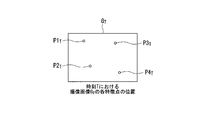
- FIG. 2A represents the feature points in the captured image G T a (P1 T, P2 T, P3 T, P4 T) at time T.
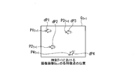
- 2B is the feature points in the captured image G T + 1 at time T + 1 (P1 T + 1 , P2 T + 1, P3 T + 1, P4 T + 1), and the movement quantity vector of the feature points in the captured image, i.e., for each feature point
- the optical flow (dP1, dP2, dP3, dP4) is shown.
- FIG. 2A, in 2B, PN T and PN T + 1 represents the same object (object point).
- the optical flow dPN feature point PN is expressed as a vector from the imaging position XPN T of PN T in the captured image G T, the image area toward the imaging position XPN T + 1 of the PN T + 1 in the captured image G T + 1 .
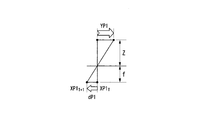
- 2C illustrates the optical flow dP1 of the feature point P1, the distance Z indicated by the distance measurement information, the focal distance f indicated by the focal length information, and the movement amount vector of the electronic device 10 based on the feature point P1.
- the relationship with YP1 is schematically represented.
- the movement amount vector YP1 represents the relative movement of the electronic device 10 with respect to the feature point P1.
- FIG. 2D schematically shows a process in which the first movement vector calculation unit 140 obtains the first movement vector from the optical flow of each feature point.
- the first movement amount vector calculation unit 140 calculates the movement amount vector YP1 of the electronic device 10 based on the feature point P1 according to the following equation (1).
- the first movement amount vector calculation unit 140 includes the movement amount vector YP2 of the electronic device 10 based on the feature point P2, the movement amount vector YP3 of the electronic device 10 based on the feature point P3, and the feature point.
- a movement amount vector YP4 of the electronic device 10 with reference to P4 is calculated (calculation process in FIG. 2D).
- the first movement amount vector calculation unit 140 determines one of the plurality of movement amount vectors calculated as described above with reference to each feature point in the captured image as the first movement amount vector. (Determination process of FIG. 2D). Specifically, the first movement amount vector calculation unit 140 has the largest number of the same or substantially the same value among a plurality of movement amount vectors calculated on the basis of each feature point. One movement amount vector is determined as the first movement amount vector. In other words, the first movement amount vector calculation unit 140 includes a plurality of movement amount vectors having the same value among a plurality of movement amount vectors calculated on the basis of each feature point as a movement amount vector group and a movement amount vector group. When the number of movement amount vectors constituting the movement amount vector is called a common degree, one movement amount vector constituting the movement amount vector group having the largest common degree is determined as a first movement amount vector.
- the values of the movement amount vectors YP1 to YP3 calculated according to the above equation (1) are As shown in 2D, they are the same or substantially the same. That is, in the four movement amount vectors YP1 to YP4, the movement amount vectors YP1 to YP3 constitute a movement amount vector group having a common value. Therefore, the movement amount vector calculation unit 140 has one movement amount vector whose value is the same or substantially the same among the four movement amount vectors YP1 to YP4, that is, “3”, that is, the degree of commonality.
- One movement amount vector (for example, movement amount vector YP1) constituting the maximum “three” movement amount vector group is determined as the first movement amount vector. Note that, according to the above equation (1), when there is a variation in each optical flow of each feature point, the above-described commonality (or commonality with respect to the total number of feature points) is small.
- the first movement amount vector calculation unit 140 instead of determining one movement amount vector constituting the movement amount vector group having the maximum degree of commonness as the first movement amount vector.
- an average value of a plurality of movement amount vectors in the case of FIG. 2D, an average value of four movement amount vectors YP1 to YP4 may be calculated and used as the first movement amount vector.
- the reliability score calculation unit 170 is weighted and normalized so that the total score of the first, second, and third reliability scores is constant (for example, 1). Calculate confidence score. Specifically, the reliability score calculation unit 170 first calculates each of the first, second, and third reliability scores (before normalization, that is, the reliability score before weighting) individually. Subsequently, the reliability score calculation unit 170 adds weights to normalize, and final first, second, and third reliability scores (after normalization, that is, reliability scores after weighting). Is calculated. Hereinafter, it demonstrates concretely using numerical formula.
- the reliability score calculation unit 170 calculates a first reliability score Po before normalization according to the following equation (2).
- the function S a (x) is a sigmoid function defined by the following equation (3).
- the sigmoid function is a function that smoothly binarizes the value of x from 0 to 1
- a is a parameter that represents the magnitude of the slope of the portion that changes from 0 to 1.
- B 0 in the above formula (1) represents the number n of feature points at which the sigmoid function is 0.5.
- N is the number of optical flows (number of feature points).
- r 0 is the optical flow commonality (small variation in optical flow). For example, it is a constant value (to avoid infinity) below a certain threshold, and the reciprocal of the standard deviation of optical flow above a certain threshold.
- a function that takes CD is the reliability of distance measurement information at the time of imaging, and k 1 , k 2 , and k 3 are coefficients.
- requiring the standard deviation of an angle can be used for the method of calculating
- a method of taking a norm after obtaining standard deviations of the x, y, and z components can be considered.
- Confidence score calculating unit 170 calculates a second confidence score P a prior normalized according to the following equation (4).
- ⁇ is a time constant.
- a (t) is an output vector (acceleration vector) from the acceleration sensor 120 at time t.
- v t ⁇ is the speed at time t ⁇ , and k 4 is a coefficient.
- the function S a (x) is a sigmoid function (see the above formula (3)).
- b a is the magnitude of the angular velocity at which the sigmoid function is 0.5, similarly to b 0 in the above equation (2).
- is the size of the vector x.
- Confidence score calculating unit 170 calculates a third confidence score P g before normalization according to the following equation (5).
- v g is the output vector of the angular velocity sensor 130 (angular velocity vector).
- k 5 is a coefficient.
- the function S a (x) is a sigmoid function (see the above formula (3)).
- b g is the magnitude of the angular velocity at which the sigmoid function is 0.5, similar to b 0 in the above equation (2).
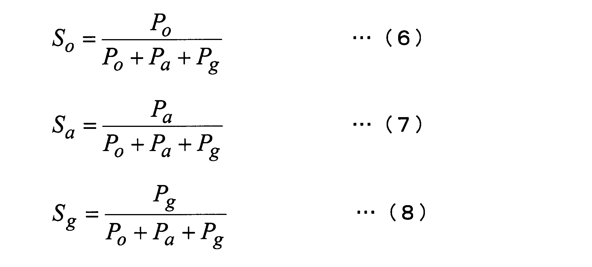
- the confidence score calculating unit 170 calculates a first confidence score S o after normalization according to the following equation (6), a second confidence score S a of the normalized according to the following equation (7) And a third reliability score S g after normalization is calculated according to the following equation (8).
- the total score of the first reliability score S o , the second reliability score S a , and the third reliability score S g is 1.
- the reliability score calculation unit 170 decreases the degree of variation of the optical flow (the motion vector at the feature point in the captured image) (ie, increases r 0 ), A first reliability score Po before normalization having a high value is calculated.
- the reliability score calculation unit 170 increases the value after normalization as the degree of variation in optical flow decreases (that is, as r 0 increases).
- a first reliability score So is calculated.
- the electronic device 10 when the electronic device 10 is moved in space when all the subjects in the captured image (for example, roads, roadside trees, parked passenger cars) are stationary, the electronic device 10 moves in the space. Since only is reflected in the optical flow, the optical flow is uniform. On the other hand, when the electronic device 10 is moved in the space in a state where a part of the subject in the captured image (for example, a passenger car traveling on the road) is moving, the electronic device 10 is moved in the space. In addition, since the moving subject is also reflected in the optical flow, the optical flow varies. Therefore, the smaller the degree of variation, the higher the first reliability score P o before normalization and the first reliability score S o after normalization.
- the reliability score calculation unit 170 calculates the first reliability score Po before normalization, which is higher as the number n of feature points is larger. Further, as shown in the above formulas (2) and (6), the reliability score calculation unit 170 increases the first reliability score So after normalization with a higher value as the number n of feature points is larger. calculate. That is, when the number of feature points of the calculation reference is large, the feature points are basically scattered throughout the entire area of the captured image. Therefore, the higher the number of feature points, the higher the first reliability score P o before normalization and the first reliability score S o after normalization.
- confidence score calculating unit 170 as shown in Equation (2) calculation, the higher the reliability C D of the distance measuring information, a high value, the first confidence score P o of prenormalized To do. Also, the confidence score calculating unit 170, the equation (2), as shown in (6), the higher the reliability C D of the distance measuring information, the high value, the first confidence score after normalization Calculate So.
- the movement amount vector of the electronic device 10 based on the feature points reflected in the values of the first reliability score P o before normalization and the first reliability score S o after normalization is a distance measurement This is because the distance Z indicated by the information is used for calculation (see the above formula (1)).
- the reliability C D for example, the number and size of each Obuhekuto area of an object that affects the variations in the distance of each feature point, and the like brightness around the case that affect ranging.
- the reliability score calculation unit 170 decreases the acceleration vector a (t) (or decreases the second movement amount vector based on the acceleration vector a (t)). , of low value, calculates a second confidence score P a prior normalization. Further, as shown in the above formulas (4) and (7), the reliability score calculation unit 170 decreases the acceleration vector a (t) (or the second movement amount vector based on the acceleration vector a (t)). the smaller), a low value, calculates a second confidence score S a after normalization.
- confidence score calculating unit 170 as shown in the equation (5), as the angular velocity vector v g is small (or, as the third movement quantity vector of which is based on the angular velocity vector v g is small), a low value to calculate a third confidence score P g before normalization. Also, the confidence score calculating unit 170, the equation (5), as shown in (8), as the angular velocity vector v g is small (or, as the third movement quantity vector of which is based on the angular velocity vector v g is small) , the lower value, to calculate a third confidence score S g after normalization.
- the moving speed calculation unit 180 receives the first reliability score S o after normalization from the reliability score calculation unit 170, the second reliability score S a after normalization, and the third reliability score after normalization.
- S g the first moving quantity vector v o, the second movement quantity vector v a, obtains a third movement quantity vector v g.
- the movement speed calculation unit 180 calculates the movement speed v * of the casing of the electronic device 10 in the space according to the following formula (9).
- the first movement amount vector calculation unit 140 has been described to calculate the first movement amount vector vo based on the optical flow, the distance measurement information, and the focal length information, other information includes Based on this, the first movement amount vector vo may be calculated.
- a first movement quantity vector calculation unit 140 without using the distance measurement information and focal length information, based on the relationship between the optical flow and the second movement quantity vector v a, a first movement quantity vector v o may be calculated.
- a first movement quantity vector calculation unit 140 the value of the second confidence score S a is in the second movement quantity vector v a at last one time point t x is equal to or greater than a predetermined threshold value
- the first movement amount vector vo may be calculated based on the ratio between the magnitude and the magnitude of the optical flow vector at this time t x and the current optical flow. In that case, the former is used as a coefficient and the latter is calculated.
- a first movement quantity vector calculation unit 140 when the value of the second confidence score S a is not less than a predetermined threshold value, as the above-mentioned ratio, the coordinate axis component of the second movement quantity vector v a are temporarily stored as values (ratio x, ratio y, ratio z) obtained by dividing each value by each value of each coordinate axis component of the representative optical flow.
- the representative optical flow is an optical flow having the largest number of the same or substantially the same value among the optical flows of a plurality of feature points (a method of determining the first movement amount vector and Determine in the same way). Subsequently, the first movement amount vector calculation unit 140 determines the current representative optical flow value.
- the first movement amount vector calculation unit 140 uses the latest ratio (ratio x, ratio y, ratio z) temporarily stored in each value of each coordinate axis component of the current representative optical flow.
- the multiplied movement amount vector is calculated and set as the first movement amount vector vo .
- the first movement amount vector vo can also be obtained by the above-described method. According to the above-described method, the first movement amount vector vo can be obtained even when distance measurement information cannot be obtained. Also, since the calculated ratio x, the ratio y, the ratio z with the value of the second movement quantity vector v a time acceleration is large, to maintain the calculation accuracy of the first movement quantity vector v o Can do.
- the first movement amount vector calculation unit 140 may calculate the first movement amount vector vo using a distance determined to be appropriate when ranging information cannot be obtained.
- a typical example of the distance determined to be appropriate is determined based on characteristics (for example, an assumed user layer and use case) of the electronic device 10 as a product (product) at the time of designing, and the electronic device 10 before shipping. It is the distance memorized in.
- the past usage record of the user of the electronic device 10 for example, the relationship between the date, place, illuminance, etc., and the measurement distance
- the current situation for example, the date, place, A distance corresponding to (illuminance) may be selected and used as a distance determined to be appropriate.
- a correspondence table of illuminance and distance is determined at the time of design, stored in the electronic device 10 before shipment, and a distance corresponding to the current illuminance is supported. It may be selected from a table and used as a distance determined to be appropriate. Further, the user may be allowed to select a distance or a method for determining the distance. For example, a button for selecting either 3 m or 10 m may be prepared and the user may select it, or the user may select whether to use the distance stored before shipment or the distance based on the past use record. Also good.
- the first movement amount vector calculation unit 140 may calculate the first movement amount vector based on the optical flow in the background portion of the captured image. For example, when a person is captured in the captured image, the first movement amount vector calculation unit 140 identifies the person's imaging area based on the face area, and uses an area other than the person's imaging area as a background portion. Good. By calculating the first movement amount vector based on the optical flow in the background portion, the degree of variation in the optical flow is reduced, and thus the first reliability score Po is increased.
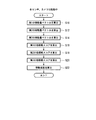
- FIG. 3 is an example of a flowchart showing a processing flow of the electronic device 10. It is assumed that the camera 110, the acceleration sensor 120, and the gyro sensor 130 are in operation at the start of the flowchart shown in FIG.
- the first movement amount vector calculation unit 140 calculates a first movement amount vector vo (step S10).
- the second movement quantity vector calculation unit 150 calculates the second movement quantity vector v a (step S12).
- Third movement quantity vector calculation unit 160 calculates the third movement quantity vector v g (Step S14).
- Confidence score calculating unit 170 the first confidence score (after normalization) is calculated S o (step S16).
- Confidence score calculating unit 170, the second confidence score (after normalization) is calculated S a (step S18).
- Confidence score calculating unit 170 calculates a third confidence score (after normalization) S g (step S20).
- the movement speed calculation unit 180 calculates the movement speed v * of the housing (step S22). Then, this flowchart ends.
- the moving speed of the housing in the space can be calculated with high accuracy.
- the second confidence score confidence score calculating unit 170 calculates (before normalization) P a is Get smaller.
- the first confidence score (after normalization) S o, the second confidence score (after normalization) S a, in relation to the third confidence score (after normalization) S g, the second The reliability score (after normalization) S a is relatively small, and the first reliability score (after normalization) S o and the third reliability score (after normalization) S g are relatively growing. Therefore, it is possible to reduce the contribution of the output value of the acceleration sensor 120 at the time of low acceleration with low reliability and accurately calculate the moving speed of the housing.
- the electronic device 10 includes the camera 110, the acceleration sensor 120, and the gyro sensor 130 as devices for calculating the movement amount vector, but the electronic device 10 does not include the gyro sensor 130. May be. That is, the electronic device 10 may be configured to include the camera 110 and the acceleration sensor 120 as a device for calculating the movement amount vector.
- the third movement amount vector calculation unit 160 is naturally unnecessary.
- the reliability score calculation unit 170 naturally has the third reliability score (before normalization) P g and the third reliability score ( After normalization) Sg is not calculated.
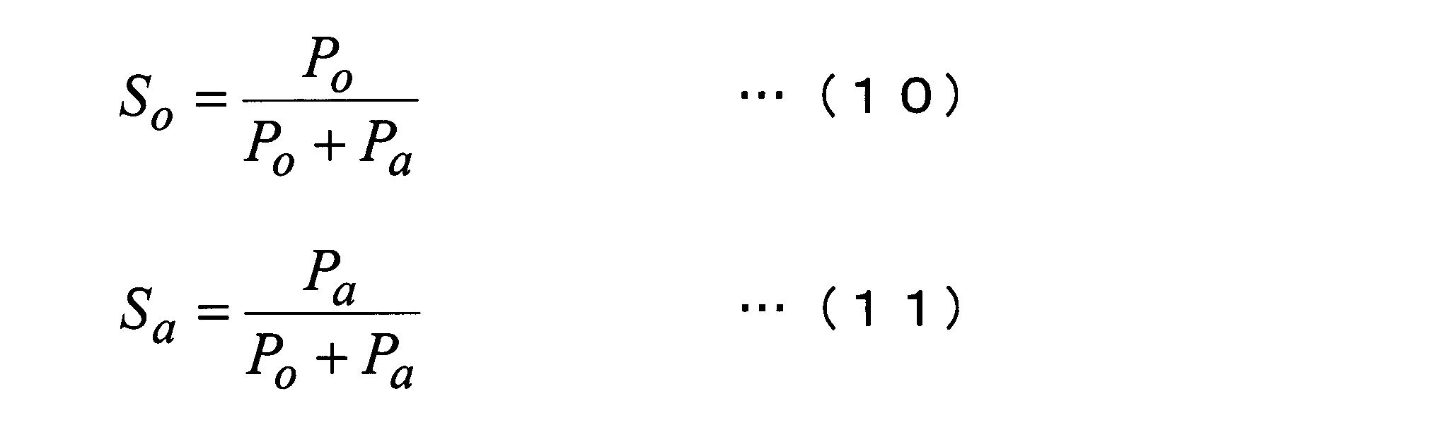
- the reliability score calculation unit 170 replaces the above equation (6) with the first reliability score (after normalization) S according to the following equation (10). o is calculated, and a second reliability score (after normalization) Sa is calculated according to the following equation (11) instead of the above equation (7).
- the moving speed calculation unit 180 moves the moving speed v of the casing of the electronic device 10 in the space according to the following formula (12) instead of the above formula (9). * Is calculated.
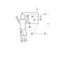
- FIG. 4 is an explanatory diagram for explaining the moving speed calculation system 1 including the electronic device 10.
- the moving speed calculation system 1 includes the above-described electronic device (second electronic device) 10 and an electronic device (first electronic device) 20 having a configuration different from that of the electronic device 10.
- the moving speed calculation system 1 calculates the moving speed of the electronic device 10 using the electronic device 10 and the electronic device 20.
- the electronic device 20 includes a projection unit that includes an output control unit, an optical system, and the like.
- the video (image) projected by the projection unit has a plurality of feature points (in the case of FIG. 4, P 1 , P 2 , P 3 ).
- the electronic device 20 may include a storage unit, and store an image projected by the projection unit in the storage unit.
- the electronic device 20 may include a communication unit, and may acquire an image projected by the projection unit from the outside (for example, the electronic device 10).
- the electronic device 10 is also provided with a communication part.
- the user directs the projection unit toward the projection surface (for example, the wall of the building), places the electronic device 20 on a stable place (for example, the ground, on the structure), and projects an image on the projection surface.
- the electronic device 10 is moved in space while the electronic device 10 is directed in a direction that allows the projected image projected onto the image to be generally captured (see FIG. 4).
- the camera 110 of the electronic device 10 captures a projection image
- the first movement amount vector calculation unit 140 can calculate the first movement amount vector based on the optical flow of the feature points in the captured image. it can. That is, even in a place where only an image including no feature point can be captured, the first movement amount vector can be calculated by projecting an image on the wall or the like using the electronic device 20. Therefore, according to the moving speed calculation system 1, the moving speed in the space of the electronic device 10 can be accurately calculated anywhere as long as there is a wall.
- the number of feature points illustrated in FIG. 2A is four, and the number of feature points illustrated in FIG. 4 is three. However, for convenience of explanation, there is a balance with the processing load of the electronic device 10. Tens or hundreds.
- a program for executing the processing of the electronic device 10 according to the embodiment of the present invention is recorded on a computer-readable recording medium, and the program recorded on the recording medium is read into a computer system and executed.
- the various processes described above related to the electronic device 10 according to the embodiment of the present invention may be performed.
- the “computer system” may include an OS and hardware such as peripheral devices. Further, the “computer system” includes a homepage providing environment (or display environment) if a WWW system is used.
- the “computer-readable recording medium” refers to a floppy (registered trademark) disk, a magneto-optical disk, an SD card, a writable nonvolatile memory such as a flash memory, a portable medium such as a CD-ROM, and a computer system.
- a built-in storage device such as a hard disk.
- the “computer-readable recording medium” means a volatile memory (for example, DRAM (Dynamic DRAM) in a computer system that becomes a server or a client when a program is transmitted through a network such as the Internet or a communication line such as a telephone line. Random Access Memory)), etc., which hold programs for a certain period of time.
- the program may be transmitted from a computer system storing the program in a storage device or the like to another computer system via a transmission medium or by a transmission wave in the transmission medium.
- the “transmission medium” for transmitting the program refers to a medium having a function of transmitting information, such as a network (communication network) such as the Internet or a communication line (communication line) such as a telephone line.
- the program may be for realizing a part of the functions described above. Furthermore, what can implement
- the electronic device is based on a camera, an acceleration sensor that detects acceleration applied to the housing, a captured image captured by the camera, and an acceleration detected by the acceleration sensor.
- a moving speed calculating unit that calculates a moving speed of the housing.
- the first movement amount vector is calculated based on the optical flow in the captured image captured by the camera
- the second movement amount vector is calculated based on the acceleration detected by the acceleration sensor.
- An amount vector calculation unit wherein the movement speed calculation unit calculates the movement speed of the housing using the first movement amount vector and the second movement amount vector calculated by the movement amount vector calculation unit. You may make it do.
- a reliability score for calculating a first reliability score indicating the reliability of the first movement amount vector and a second reliability score indicating the reliability of the second movement amount vector is a reliability score for calculating a first reliability score indicating the reliability of the first movement amount vector and a second reliability score indicating the reliability of the second movement amount vector.
- the moving speed calculating unit further includes a calculating unit, using the first moving amount vector, the second moving amount vector, the first reliability score, and the second reliability score, You may make it calculate the moving speed of the said housing
- the reliability score calculation unit calculates the first reliability score having a higher value as the degree of variation of the motion vector at the feature point in the captured image is smaller, and lower as the acceleration is smaller.
- the second confidence score of the value may be calculated.
- the reliability score calculation unit calculates the first reliability score having a higher value as the number of feature points in the captured image is larger, and the reliability of distance measurement information at the time of imaging is higher.
- the first reliability score having a higher value may be calculated.
- the electronic apparatus further includes an angular velocity sensor that detects an angular velocity of the housing, and the movement amount vector calculation unit calculates a third movement amount vector based on the angular velocity detected by the angular velocity sensor, and the reliability
- the degree score calculation unit calculates a third reliability score indicating the reliability of the third movement amount vector
- the movement speed calculation unit includes the first movement amount vector, the second movement amount vector
- the moving speed of the housing may be calculated using the third movement amount vector, the first reliability score, the second reliability score, and the third reliability score.
- the reliability score calculation unit may calculate the third reliability score having a lower value as the angular velocity is smaller.
- the movement amount vector calculation unit may calculate the first movement amount vector from distance measurement information at the time of imaging, focal length information at the time of imaging, and the optical flow. .
- the movement amount vector calculation unit includes the value of the second movement amount vector at the most recent time point at which the value of the second reliability score is equal to or greater than a predetermined threshold value and the optical value at the time point.
- the first movement amount vector may be calculated based on the ratio to the flow and the current optical flow.
- the movement amount vector calculation unit may calculate the first movement amount vector based on an optical flow in a background portion of the captured image.
Landscapes
- Physics & Mathematics (AREA)
- General Physics & Mathematics (AREA)
- Engineering & Computer Science (AREA)
- Electromagnetism (AREA)
- Power Engineering (AREA)
- Studio Devices (AREA)
- Image Analysis (AREA)
Abstract
電子機器は、カメラと、筐体に加わる加速度を検出する加速度センサと、前記カメラによって撮像された撮像画像と、前記加速度センサによって検出された加速度とに基づいて前記筐体の移動速度を算出する移動速度算出部と、を備える。
Description
本発明は、電子機器及び移動速度算出システムに関する。
本願は、2011年10月5日に出願された特願2011-220834号に基づき優先権を主張し、その内容をここに援用する。
本願は、2011年10月5日に出願された特願2011-220834号に基づき優先権を主張し、その内容をここに援用する。
従来、加速度センサを備える電子機器が知られている(例えば、特許文献1参照)。
しかしながら、加速度センサを用いて自機器の移動速度を算出した場合、算出した移動速度に誤差が生じ易いという問題がある。特に、筐体に加わる加速度が小さい場合に、移動速度を精度良く算出できないという問題がある。
本発明の態様は、空間における筐体の移動速度を精度良く算出する技術を提供することを目的とする。
本発明の態様は、空間における筐体の移動速度を精度良く算出する技術を提供することを目的とする。
本発明の一態様である電子機器は、カメラと、筐体に加わる加速度を検出する加速度センサと、前記カメラによって撮像された撮像画像と、前記加速度センサによって検出された加速度とに基づいて前記筐体の移動速度を算出する移動速度算出部と、を備える。
本発明の他の態様である移動速度算出システムは、第1の電子機器と第2の電子機器とを備え、前記第1の電子機器及び前記第2の電子機器を用いて前記第2の電子機器の移動速度を算出する移動速度算出システムであって、前記第1の電子機器は、特徴点を有する映像を投影する投影部を有し、前記第2の電子機器は、前記投影部によって投影された投影像を撮像するカメラと、前記第2の電子機器に加わる加速度を検出する加速度センサと、前記カメラによって撮像された前記投影像内の前記特徴点のオプティカルフローに基づいて第1の移動量ベクトルを算出し、前記加速度センサによって検出された加速度に基づいて第2の移動量ベクトルを算出する移動量ベクトル算出部と、前記第1の移動量ベクトルの信頼度を示す第1の信頼度スコア、及び、前記第2の移動量ベクトルの信頼度を示す第2の信頼度スコアを算出する信頼度スコア算出部と、前記第1の移動量ベクトル、前記第2の移動量ベクトル、前記第1の信頼度スコア、及び、前記第2の信頼度スコアを用いて、空間での前記第2の電子機器の移動速度を算出する移動速度算出部とを有する。
本発明の態様によれば、空間における筐体の移動速度を精度良く算出することができる。
以下、図面を参照しながら本発明の実施形態について説明する。図1は、本発明の実施形態による電子機器10の機能ブロック図の一例である。
電子機器10は、ハンディサイズの機器であって、図1に示すように、カメラ110、加速度センサ120、ジャイロセンサ(角速度センサ)130、第1の移動量ベクトル算出部(移動量ベクトル算出部)140、第2の移動量ベクトル算出部(移動量ベクトル算出部)150、第3の移動量ベクトル算出部(移動量ベクトル算出部)160、信頼度スコア算出部170、及び、移動速度算出部180を備える。
カメラ110は、カメラユニット(モジュール)であって、例えば、距離を測定する測距部と、レンズを含む光学系と、光学系によって結像された被写体の像を光電変換する撮像素子と、撮像素子から出力されるアナログ信号を増幅するアンプと、アンプから出力されるアナログ信号をデジタル信号に変換するAD変換部と、AD変換部からの出力に基づいて所定の形式の画像(動画像、静止画像)を生成する画像生成部(ASIC、DSP)とを備える。
なお、カメラ110の構成のうち、光学系及び撮像素子以外の構成の一部又は全部についてカメラ110から独立した構成としてもよい。例えば、測距部、画像生成部は、カメラ110の構成要素ではなく、カメラ110とは別に電子機器10が備える構成要素であってもよい(アンプ、AD変換部についても同様である)。但し、以下の説明においては、カメラ110が、上述の構成を全部備えるものとして説明する。
なお、カメラ110の構成のうち、光学系及び撮像素子以外の構成の一部又は全部についてカメラ110から独立した構成としてもよい。例えば、測距部、画像生成部は、カメラ110の構成要素ではなく、カメラ110とは別に電子機器10が備える構成要素であってもよい(アンプ、AD変換部についても同様である)。但し、以下の説明においては、カメラ110が、上述の構成を全部備えるものとして説明する。
カメラ110は、撮像画像を第1の移動量ベクトル算出部140に出力する。また、カメラ110は、撮像時の測距情報、及び、撮像時の焦点距離情報を第1の移動量ベクトル算出部140に出力する。
加速度センサ120は、筐体に加わる加速度を検出する。加速度センサ120は、加速度の検出値を第2の移動量ベクトル算出部150に出力する。
ジャイロセンサ130は、筐体の角速度を検出する。ジャイロセンサ130は、角速度の検出値を第3の移動量ベクトル算出部160に出力する。
第1の移動量ベクトル算出部140は、カメラ110によって撮像された撮像画像におけるオプティカルフロー(特徴点における動きベクトル)に基づいて筐体の移動量ベクトル(以下、オプティカルフローに基づく筐体の移動量ベクトルを「第1の移動量ベクトル」という)を算出する。第1の移動量ベクトルは、XYZ座標上の単位時間の移動量、即ち、速度ベクトルである。
第1の移動量ベクトル算出部140は、算出した第1の移動量ベクトルを信頼度スコア算出部170に出力する。また、第1の移動量ベクトル算出部140は、カメラ110から取得した測距情報、焦点距離情報を信頼度スコア算出部170に出力する。
なお、第1の移動量ベクトル算出部140の処理の詳細は後述する。
なお、第1の移動量ベクトル算出部140の処理の詳細は後述する。
第2の移動量ベクトル算出部150は、加速度センサ120によって検出された加速度に基づく筐体の移動量ベクトル(以下、加速度に基づく筐体の移動量ベクトルを「第2の移動量ベクトル」という)を算出する。第2の移動量ベクトルは、XYZ座標上の単位時間の移動量、即ち、速度ベクトルである。
第2の移動量ベクトル算出部150は、算出した第2の移動量ベクトルを信頼度スコア算出部170に出力する。また、第2の移動量ベクトル算出部150は、更に、加速度センサ120から取得した検出値(加速度)を信頼度スコア算出部170に出力してもよい。
第3の移動量ベクトル算出部160は、ジャイロセンサ130によって検出された角速度に基づく筐体の移動量ベクトル(以下、角速度に基づく筐体の移動量ベクトルを「第3の移動量ベクトル」という)を算出する。第3の移動量ベクトルは、XYZ座標上の単位時間の移動量、即ち、速度ベクトルである。なお、第3の移動量ベクトル算出部160は、例えば、回転軸方向の角速度をXYZ座標上の速度成分に分解するなどの既知の手法によって、第3の移動量ベクトルを算出する。
第3の移動量ベクトル算出部160は、算出した第3の移動量ベクトルを信頼度スコア算出部170に出力する。また、第3の移動量ベクトル算出部160は、更に、ジャイロセンサ130から取得した検出値(角速度)を信頼度スコア算出部170に出力してもよい。
信頼度スコア算出部170は、第1の移動量ベクトルの信頼度を示す第1の信頼度スコアを算出する。また、信頼度スコア算出部170は、第2の移動量ベクトルの信頼度を示す第2の信頼度スコアを算出する。また、信頼度スコア算出部170は、第3の移動量ベクトルの信頼度を示す第3の信頼度スコアを算出する。
信頼度スコア算出部170は、算出した各信頼度スコア(第1の信頼度スコア、第2の信頼度スコア、第3の信頼度スコア)を移動速度算出部180に出力する。また、信頼度スコア算出部170は、第1の移動量ベクトル算出部140から取得した第1の移動量ベクトル、第2の移動量ベクトル算出部150から取得した第2の移動量ベクトル、及び、第3の移動量ベクトル算出部160から取得した第3の移動量ベクトルを移動速度算出部180に出力する。
なお、信頼度スコア算出部170の処理の詳細は後述する。
信頼度スコア算出部170は、算出した各信頼度スコア(第1の信頼度スコア、第2の信頼度スコア、第3の信頼度スコア)を移動速度算出部180に出力する。また、信頼度スコア算出部170は、第1の移動量ベクトル算出部140から取得した第1の移動量ベクトル、第2の移動量ベクトル算出部150から取得した第2の移動量ベクトル、及び、第3の移動量ベクトル算出部160から取得した第3の移動量ベクトルを移動速度算出部180に出力する。
なお、信頼度スコア算出部170の処理の詳細は後述する。
移動速度算出部180は、第1、第2、第3の移動量ベクトル、第1、第2、第3の信頼度スコアを用いて、空間での電子機器10の筐体の移動速度を算出する。
なお、移動速度算出部180の具体的な処理については後述する。
なお、移動速度算出部180の具体的な処理については後述する。
続いて、第1の移動量ベクトル算出部140の処理について詳しく説明する。第1の移動量ベクトル算出部140は、カメラ110から時間的に連続する複数枚の撮像画像、撮像時の測距情報、及び、撮像時の焦点距離情報を取得する。第1の移動量ベクトル算出部140は、カメラ110から取得した撮像画像から特徴点のオプティカルフローを算出し、算出したオプティカルフローと、測距情報と、焦点距離情報とから、第1の移動量ベクトルを算出する。以下、図面を用いて具体的に説明する。
図2A~2Dは、第1の移動量ベクトル算出部140の処理を説明するための説明図である。具体的には、図2Aは、時刻Tにおける撮像画像GT内の各特徴点(P1T、P2T、P3T、P4T)を表している。図2Bは、時刻T+1における撮像画像GT+1内の各特徴点(P1T+1、P2T+1、P3T+1、P4T+1)、及び、撮像画像上の各特徴点の移動量ベクトル、即ち、各特徴点のオプティカルフロー(dP1、dP2、dP3、dP4)を表している。なお、図2A、2Bにおいて、PNTとPNT+1は、同一の被写体(物点)を表している。また、特徴点PNのオプティカルフローdPNは、撮像画像GT内のPNTの撮像位置XPNTから、撮像画像GT+1内のPNT+1の撮像位置XPNT+1に向かう画像領域内のベクトルとして表される。例えば、dP1は、P1Tの撮像位置XP1Tから、P1T+1の撮像位置XP1T+1に向かう画像領域内のベクトルである。
また、図2Cは、特徴点P1のオプティカルフローdP1と、測距情報によって示される距離Zと、焦点距離情報によって示される焦点距離fと、特徴点P1を基準とした電子機器10の移動量ベクトルYP1との関係を模式的に表している。なお、移動量ベクトルYP1は、特徴点P1に対する電子機器10の相対的な移動を表している。
また、図2Dは、第1の移動量ベクトル算出部140が、各特徴点のオプティカルフローから第1の移動量ベクトルを得る過程を模式的に表している。
図2Cの関係から、第1の移動量ベクトル算出部140は、下記式(1)に従って特徴点P1を基準とした電子機器10の移動量ベクトルYP1を算出する。
YP1=Z×dP1/f…(1)
同様に、第1の移動量ベクトル算出部140は、特徴点P2を基準とした電子機器10の移動量ベクトルYP2、特徴点P3を基準とした電子機器10の移動量ベクトルYP3、及び、特徴点P4を基準とした電子機器10の移動量ベクトルYP4を算出する(図2Dの算出過程)。
次に、第1の移動量ベクトル算出部140は、撮像画像内のそれぞれの特徴点を基準として上述のように算出した複数個の移動量ベクトルの1つを第1の移動量ベクトルとして決定する(図2Dの決定過程)。
具体的には、第1の移動量ベクトル算出部140は、それぞれの特徴点を基準として算出した複数個の移動量ベクトルのうち、値が同一又は実質的に同一である個数が最多である1つの移動量ベクトルを第1の移動量ベクトルとして決定する。換言すれば、第1の移動量ベクトル算出部140は、各特徴点を基準として算出した複数個の移動量ベクトルにおいて、値が共通する複数の移動量ベクトルを移動量ベクトル群、移動量ベクトル群を構成する移動量ベクトルの個数を共通度と呼ぶ場合に、共通度が最大である移動量ベクトル群を構成する1つの移動量ベクトルを第1の移動量ベクトルとして決定する。
具体的には、第1の移動量ベクトル算出部140は、それぞれの特徴点を基準として算出した複数個の移動量ベクトルのうち、値が同一又は実質的に同一である個数が最多である1つの移動量ベクトルを第1の移動量ベクトルとして決定する。換言すれば、第1の移動量ベクトル算出部140は、各特徴点を基準として算出した複数個の移動量ベクトルにおいて、値が共通する複数の移動量ベクトルを移動量ベクトル群、移動量ベクトル群を構成する移動量ベクトルの個数を共通度と呼ぶ場合に、共通度が最大である移動量ベクトル群を構成する1つの移動量ベクトルを第1の移動量ベクトルとして決定する。
図2Dの場合、特徴点P1~P3のオプティカルフローdP1~dP3は同一又は実質的に同一であるため、上記式(1)に従って算出される、移動量ベクトルYP1~YP3のそれぞれの値は、図2Dに示すように同一又は実質的に同一となる。つまり、4つの移動量ベクトルYP1~YP4において、移動量ベクトルYP1~YP3は値が共通する移動量ベクトル群を構成する。
従って、移動量ベクトル算出部140は、4つの移動量ベクトルYP1~YP4において、値が同一又は実質的に同一である個数が最多の「3個」である1つの移動量ベクトル、つまり共通度が最大の「3個」である移動量ベクトル群を構成する1つの移動量ベクトル(例えば、移動量ベクトルYP1)を第1の移動量ベクトルとして決定する。
なお、上記式(1)によれば、各特徴点の各オプティカルフローにばらつきがある場合、上述の共通度(若しくは、特徴点の総数に対する共通度)は小さくなる。
従って、移動量ベクトル算出部140は、4つの移動量ベクトルYP1~YP4において、値が同一又は実質的に同一である個数が最多の「3個」である1つの移動量ベクトル、つまり共通度が最大の「3個」である移動量ベクトル群を構成する1つの移動量ベクトル(例えば、移動量ベクトルYP1)を第1の移動量ベクトルとして決定する。
なお、上記式(1)によれば、各特徴点の各オプティカルフローにばらつきがある場合、上述の共通度(若しくは、特徴点の総数に対する共通度)は小さくなる。
なお、第1の移動量ベクトル算出部140は、上述のように、共通度が最大である移動量ベクトル群を構成する1つの移動量ベクトルを第1の移動量ベクトルとして決定することに代えて、複数個の移動量ベクトルの平均値(図2Dの場合、4つの移動量ベクトルYP1~YP4の平均値)を算出し、第1の移動量ベクトルとしてしてもよい。
続いて、信頼度スコア算出部170の処理について詳しく説明する。信頼度スコア算出部170は、第1、第2、第3信頼度スコアの合計スコアが一定(例えば、1)になるように重みを付して正規化した第1、第2、第3の信頼度スコアを算出する。
具体的には、信頼度スコア算出部170は、まず、第1、第2、第3のそれぞれの信頼度スコア(正規化前、即ち、重み付け前の信頼度スコア)を個別に算出する。続いて、信頼度スコア算出部170は、重みを付して正規化し、最終的な第1、第2、第3のそれぞれの信頼度スコア(正規化後、即ち、重み付け後の信頼度スコア)を算出する。以下、数式を用いて具体的に説明する。
具体的には、信頼度スコア算出部170は、まず、第1、第2、第3のそれぞれの信頼度スコア(正規化前、即ち、重み付け前の信頼度スコア)を個別に算出する。続いて、信頼度スコア算出部170は、重みを付して正規化し、最終的な第1、第2、第3のそれぞれの信頼度スコア(正規化後、即ち、重み付け後の信頼度スコア)を算出する。以下、数式を用いて具体的に説明する。
信頼度スコア算出部170は、下記式(2)に従って正規化前の第1の信頼度スコアPoを算出する。

また、nは、オプティカルフローの点数(特徴点の個数)である。r0は、オプティカルフローの共通度(オプティカルフローのばらつきの小ささ)であって、例えば、ある閾値未満では一定値(無限大を避けるため)、ある閾値以上ではオプティカルフローの標準偏差の逆数をとる関数によって表される。CDは、撮像時の測距情報の信頼度、k1、k2、k3は係数である。
なお、オプティカルフローの標準偏差を求める方法は、角度の標準偏差を求める方法を用いることができる。代替的には、x、y、z各成分の標準偏差を求めてからノルムをとる方法が考えられる。

信頼度スコア算出部170は、下記式(4)に従って正規化前の第2の信頼度スコアPaを算出する。

信頼度スコア算出部170は、下記式(5)に従って正規化前の第3の信頼度スコアPgを算出する。

また、信頼度スコア算出部170は、下記式(6)に従って正規化後の第1の信頼度スコアSoを算出し、下記式(7)に従って正規化後の第2の信頼度スコアSaを算出し、下記式(8)に従って正規化後の第3の信頼度スコアSgを算出する。なお、第1の信頼度スコアSo、第2の信頼度スコアSa、第3の信頼度スコアSgの合計スコアは1となる。
即ち、信頼度スコア算出部170は、上記式(2)に示すように、オプティカルフロー(撮像画像内の特徴点における動きベクトル)のばらつきの程度が小さいほど(即ち、r0が大きいほど)、高い値の、正規化前の第1の信頼度スコアPoを算出する。
また、信頼度スコア算出部170は、上記式(2)、(6)に示すように、オプティカルフローのばらつきの程度が小さいほど(即ち、r0が大きいほど)、高い値の、正規化後の第1の信頼度スコアSoを算出する。
また、信頼度スコア算出部170は、上記式(2)、(6)に示すように、オプティカルフローのばらつきの程度が小さいほど(即ち、r0が大きいほど)、高い値の、正規化後の第1の信頼度スコアSoを算出する。
つまり、撮像画像内の全ての被写体(例えば、道路、街路樹、駐車した乗用車)が静止している状態において、電子機器10を空間にて移動させたときは、電子機器10の空間での移動のみがオプティカルフローに反映されるため、オプティカルフローは一律になる。一方、撮像画像内の一部の被写体(例えば、道路を走行中の乗用車)が移動している状態において、電子機器10を空間にて移動させたときは、電子機器10の空間での移動に加え、移動している被写体もオプティカルフローに反映されるため、オプティカルフローにばらつきが生じる。従って、ばらつきの程度が小さいときほど、正規化前の第1の信頼度スコアPo、正規化後の第1の信頼度スコアSoを高くしている。
また、信頼度スコア算出部170は、上記式(2)に示すように、特徴点の数nが多いほど、高い値の、正規化前の第1の信頼度スコアPoを算出する。また、信頼度スコア算出部170は、上記式(2)、(6)に示すように、特徴点の数nが多いほど、高い値の、正規化後の第1の信頼度スコアSoを算出する。つまり、算出基準の特徴点の数が多い場合、基本的に、撮像画像の全領域に特徴点が散らばっていることになる。従って、特徴点の数が多いときほど、正規化前の第1の信頼度スコアPo、正規化後の第1の信頼度スコアSoを高くしている。
また、信頼度スコア算出部170は、上記式(2)に示すように、測距情報の信頼度CDが高いほど、高い値の、正規化前の第1の信頼度スコアPoを算出する。また、信頼度スコア算出部170は、上記式(2)、(6)に示すように、測距情報の信頼度CDが高いほど、高い値の、正規化後の第1の信頼度スコアSoを算出する。正規化前の第1の信頼度スコアPo、及び、正規化後の第1の信頼度スコアSoの値に反映される特徴点を基準とした電子機器10の移動量ベクトルは、測距情報によって示される距離Zを用いて算出しているからである(上記式(1)参照)。なお、信頼度CDは、例えば、特徴点毎の距離のばらつきに影響するオブジェクトの個数及び各オブヘクト領域の大きさ、測距に影響する場合の周囲の明るさなどである。
また、信頼度スコア算出部170は、上記式(4)に示すように、加速度ベクトルa(t)が小さいほど(又は、加速度ベクトルa(t)に基づく第2の移動量ベクトルが小さいほど)、低い値の、正規化前の第2の信頼度スコアPaを算出する。また、信頼度スコア算出部170は、上記式(4)、(7)に示すように、加速度ベクトルa(t)が小さいほど(又は、加速度ベクトルa(t)に基づく第2の移動量ベクトルが小さいほど)、低い値の、正規化後の第2の信頼度スコアSaを算出する。
また、信頼度スコア算出部170は、上記式(5)に示すように、角速度ベクトルvgが小さいほど(又は、角速度ベクトルvgに基づく第3の移動量ベクトルが小さいほど)、低い値の、正規化前の第3の信頼度スコアPgを算出する。また、信頼度スコア算出部170は、上記式(5)、(8)に示すように、角速度ベクトルvgが小さいほど(又は、角速度ベクトルvgに基づく第3の移動量ベクトルが小さいほど)、低い値の、正規化後の第3の信頼度スコアSgを算出する。
続いて、移動速度算出部180の処理を具体的に説明する。移動速度算出部180は、信頼度スコア算出部170から正規化後の第1の信頼度スコアSo、正規化後の第2の信頼度スコアSa、正規化後の第3の信頼度スコアSg、第1の移動量ベクトルvo、第2の移動量ベクトルva、第3の移動量ベクトルvgを取得する。移動速度算出部180は、下記式(9)に従って空間での電子機器10の筐体の移動速度v*を算出する。
v*=So×vo+Sa×va+Sg+vg…(9)
なお、第1の移動量ベクトル算出部140は、オプティカルフロー、測距情報、及び、焦点距離情報に基づいて、第1の移動量ベクトルvoを算出する旨を説明したが、他の情報に基づいて、第1の移動量ベクトルvoを算出してもよい。
例えば、第1の移動量ベクトル算出部140は、測距情報及び焦点距離情報を用いることなく、オプティカルフローと第2の移動量ベクトルvaとの関係に基づいて、第1の移動量ベクトルvoを算出してもよい。具体的には、第1の移動量ベクトル算出部140は、第2の信頼度スコアSaの値が所定の閾値以上である直近の1つの時点txにおける第2の移動量ベクトルvaの大きさとこの時点txのオプティカルフローのベクトルの大きさとの比率、及び、現時点におけるオプティカルフローに基づいて第1の移動量ベクトルvoを算出してもよい。その場合、前者を係数として後者に掛ける計算を行う。
例えば、第1の移動量ベクトル算出部140は、第2の信頼度スコアSaの値が所定の閾値以上であるときに、上述の比率として、第2の移動量ベクトルvaの各座標軸成分の各値を、代表のオプティカルフローの各座標軸成分の各値によってそれぞれに除算した値(比率x,比率y,比率z)を一時記憶する。代表のオプティカルフローとは、複数の特徴点のオプティカルフローの中から、値が同一又は実質的に同一である個数が最多の1つのオプティカルフローである(第1の移動量ベクトルを決定する方法と同様の方法で決定する)。続いて、第1の移動量ベクトル算出部140は、現時点の代表のオプティカルフローの値を決定する。続いて、第1の移動量ベクトル算出部140は、現時点の代表のオプティカルフローの各座標軸成分の各値に、一時記憶している最新のそれぞれの比率(比率x,比率y,比率z)を乗算した移動量ベクトルを算出し、第1の移動量ベクトルvoとする。
微小時間内であれば、電子機器10の移動方向は同一(直線運動)である(即ち、各座標軸成分毎に見たときの、加速度センサ120の出力値とオプティカルフローの値は比例関係にある)と見なせるため、上述の方法によっても、第1の移動量ベクトルvoを求めることができる。上述の方法によれば、測距情報を得られない場合にも、第1の移動量ベクトルvoを求めることができる。また、加速度が大きいときの第2の移動量ベクトルvaの値を用いて比率x,比率y,比率zを算出しているため、第1の移動量ベクトルvoの算出精度を維持することができる。
なお、第1の移動量ベクトル算出部140は、測距情報を得られない場合には、妥当と判断される距離を用いて、第1の移動量ベクトルvoを算出してもよい。妥当と判断される距離の典型的な例は、設計時に、電子機器10の製品(商品)としての特性(例えば、想定するユーザ層、使用ケース)に基づいて決定し、出荷前に電子機器10内に記憶しておく距離である。また、電子機器10のユーザの過去の使用実績(例えば、日時、場所、照度などと測定距離との関係)を記憶しておき、使用実績を参照し、現在の状況(例えば、日時、場所、照度)に対応する距離を選択し、妥当と判断される距離として用いてもよい。また、電子機器10が測距機能をそもそも有しない場合、設計時に、照度と距離の対応テーブルを決定し、出荷前に電子機器10内に記憶しておき、現在の照度に対応する距離を対応テーブルから選択し、妥当と判断される距離として用いてもよい。
また、ユーザに距離、又は、距離の決定方法を選択させるようにしてもよい。例えば、3m、10mの何れかを選択するボタンを用意しユーザに選択させてもよいし、上述の出荷前に記憶した距離を用いるか、過去の使用実績に基づく距離を用いるかを選択させてもよい。
また、ユーザに距離、又は、距離の決定方法を選択させるようにしてもよい。例えば、3m、10mの何れかを選択するボタンを用意しユーザに選択させてもよいし、上述の出荷前に記憶した距離を用いるか、過去の使用実績に基づく距離を用いるかを選択させてもよい。
また、第1の移動量ベクトル算出部140は、撮像画像の背景部分におけるオプティカルフローに基づいて第1の移動量ベクトルを算出してもよい。例えば、撮像画像中に人物が撮像されている場合、第1の移動量ベクトル算出部140は、顔領域に基づいて人物の撮像領域を特定し、人物の撮像領域以外の領域を背景部分としてもよい。背景部分におけるオプティカルフローに基づいて第1の移動量ベクトルを算出することにより、オプティカルフローのばらつきの程度が小さくなるため、第1の信頼度スコアPoは高くなる。
図3は、電子機器10の処理の流れを示すフローチャートの一例である。なお、図3に示すフローチャートの開始時において、カメラ110、加速度センサ120及びジャイロセンサ130は動作中であるものとする。
図3において、第1の移動量ベクトル算出部140は、第1の移動量ベクトルvoを算出する(ステップS10)。第2の移動量ベクトル算出部150は、第2の移動量ベクトルvaを算出する(ステップS12)。第3の移動量ベクトル算出部160は、第3の移動量ベクトルvgを算出する(ステップS14)。
信頼度スコア算出部170は、第1の信頼度スコア(正規化後)Soを算出する(ステップS16)。信頼度スコア算出部170は、第2の信頼度スコア(正規化後)Saを算出する(ステップS18)。信頼度スコア算出部170は、第3の信頼度スコア(正規化後)Sgを算出する(ステップS20)。移動速度算出部180は、筐体の移動速度v*を算出する(ステップS22)。そして、本フローチャートは終了する。
以上、電子機器10によれば、空間における筐体の移動速度を精度良く算出することができる。例えば、筐体に加わる加速度が小さい場合には、即ち、加速度ベクトルa(t)が小さい場合には、信頼度スコア算出部170が算出する第2の信頼度スコア(正規化前)Paは小さくなる。よって、第1の信頼度スコア(正規化後)So、第2の信頼度スコア(正規化後)Sa、第3の信頼度スコア(正規化後)Sgの関係において、第2の信頼度スコア(正規化後)Saは相対的に小さくなり、第1の信頼度スコア(正規化後)So、及び、第3の信頼度スコア(正規化後)Sgは相対的に大きくなる。従って、信頼性の低い低加速度時の加速度センサ120の出力値の寄与度を減らして、筐体の移動速度を精度良く算出することができる。
なお、上記実施形態において、電子機器10は、移動量ベクトルを算出するデバイスとして、カメラ110と加速度センサ120とジャイロセンサ130とを備えているが、電子機器10は、ジャイロセンサ130を備えていなくてもよい。つまり、電子機器10は、移動量ベクトルを算出するデバイスとして、カメラ110と加速度センサ120とを有する構成としてもよい。電子機器10がジャイロセンサ130を有しない場合には、当然に、第3の移動量ベクトル算出部160は不要である。また、電子機器10がジャイロセンサ130を有しない場合には、信頼度スコア算出部170は、当然に、第3の信頼度スコア(正規化前)Pg、及び、第3の信頼度スコア(正規化後)Sgを算出しない。
また、電子機器10がジャイロセンサ130を有しない場合には、信頼度スコア算出部170は、上記式(6)に代えて下記式(10)に従って第1の信頼度スコア(正規化後)Soを算出し、上記式(7)に代えて下記式(11)に従って第2の信頼度スコア(正規化後)Saを算出する。
また、電子機器10がジャイロセンサ130を有しない場合には、移動速度算出部180は、上記式(9)に代えて下記式(12)に従って空間での電子機器10の筐体の移動速度v*を算出する。
v*=So×vo+Sa×va…(12)
図4は、電子機器10を含む移動速度算出システム1を説明するための説明図である。
移動速度算出システム1は、図4に示すように、上述の電子機器(第2の電子機器)10と、電子機器10とは構成が異なる電子機器(第1の電子機器)20とを備える。移動速度算出システム1は、電子機器10、及び電子機器20を用いて、電子機器10の移動速度を算出する。
移動速度算出システム1は、図4に示すように、上述の電子機器(第2の電子機器)10と、電子機器10とは構成が異なる電子機器(第1の電子機器)20とを備える。移動速度算出システム1は、電子機器10、及び電子機器20を用いて、電子機器10の移動速度を算出する。
電子機器20は、出力制御部、光学系などから構成される投影部を備える。投影部によって投影される映像(画像)は、複数の特徴点(図4の場合、P1、P2、P3)を有する。なお、電子機器20は、記憶部を備え、投影部によって投影される映像を記憶部内に記憶していてもよい。また、電子機器20は、通信部を備え、投影部によって投影される映像を外部(例えば、電子機器10)から取得してもよい。なお、電子機器20が外部から映像を取得する態様の場合、電子機器10も通信部を備える。
ユーザは、投影面(例えば、建造物の壁)に投射部を向け、安定した場所(例えば、地面、構造物の上)に電子機器20を置いて投影面に映像を投影させるとともに、投影面に投影された投影像を概ね撮像できる向きに電子機器10を向けたまま、電子機器10を空間で移動させる(図4参照)。
これにより、電子機器10のカメラ110は投影像を撮像し、第1の移動量ベクトル算出部140は、撮像画像内の特徴点のオプティカルフローに基づいて第1の移動量ベクトルを算出することができる。つまり、特徴点を含まない画像しか撮像できないような場所においても、電子機器20を用いて壁などに映像を映すことにより、第1の移動量ベクトルを算出することができるようになる。従って、移動速度算出システム1によれば、壁さえあれば、どこでも、電子機器10の空間での移動速度を精度よく算出することができる。
なお、図2Aに例示した特徴点の数は4個、図4に例示した特徴点の数は3個であるが、説明の便宜上であって、電子機器10の処理負荷との兼ね合いもあるが、数十個、数百個程度とすることができる。
なお、本発明の実施形態による電子機器10の処理を実行するためのプログラムをコンピュータ読み取り可能な記録媒体に記録して、この記録媒体に記録されたプログラムをコンピュータシステムに読み込ませ、実行することにより、本発明の実施形態による電子機器10に係る上述した種々の処理を行ってもよい。なお、ここでいう「コンピュータシステム」とは、OSや周辺機器等のハードウェアを含むものであってもよい。また、「コンピュータシステム」は、WWWシステムを利用している場合であれば、ホームページ提供環境(あるいは表示環境)も含むものとする。また、「コンピュータ読み取り可能な記録媒体」とは、フロッピー(登録商標)ディスク、光磁気ディスク、SDカード、フラッシュメモリ等の書き込み可能な不揮発性メモリ、CD-ROM等の可搬媒体、コンピュータシステムに内蔵されるハードディスク等の記憶装置のことをいう。
さらに「コンピュータ読み取り可能な記録媒体」とは、インターネット等のネットワークや電話回線等の通信回線を介してプログラムが送信された場合のサーバやクライアントとなるコンピュータシステム内部の揮発性メモリ(例えばDRAM(Dynamic Random Access Memory))のように、一定時間プログラムを保持しているものも含むものとする。また、上記プログラムは、このプログラムを記憶装置等に格納したコンピュータシステムから、伝送媒体を介して、あるいは、伝送媒体中の伝送波により他のコンピュータシステムに伝送されてもよい。ここで、プログラムを伝送する「伝送媒体」は、インターネット等のネットワーク(通信網)や電話回線等の通信回線(通信線)のように情報を伝送する機能を有する媒体のことをいう。また、上記プログラムは、前述した機能の一部を実現するためのものであっても良い。さらに、前述した機能をコンピュータシステムにすでに記録されているプログラムとの組み合わせで実現できるもの、いわゆる差分ファイル(差分プログラム)であっても良い。
以上、この発明の実施形態について図面を参照して詳述してきたが、具体的な構成はこの実施形態に限られるものではなく、この発明の要旨を逸脱しない範囲の設計等も含まれる。
本発明の一実施形態において、電子機器は、カメラと、筐体に加わる加速度を検出する加速度センサと、前記カメラによって撮像された撮像画像と、前記加速度センサによって検出された加速度とに基づいて前記筐体の移動速度を算出する移動速度算出部と、を備える。
上記電子機器において、前記カメラによって撮像された撮像画像におけるオプティカルフローに基づいて第1の移動量ベクトルを算出し、前記加速度センサによって検出された加速度に基づいて第2の移動量ベクトルを算出する移動量ベクトル算出部を備え、前記移動速度算出部は、前記移動量ベクトル算出部で算出された前記第1の移動量ベクトル及び前記第2の移動量ベクトルを用いて前記筐体の移動速度を算出するようにしてもよい。
上記電子機器において、前記第1の移動量ベクトルの信頼度を示す第1の信頼度スコア、及び、前記第2の移動量ベクトルの信頼度を示す第2の信頼度スコアを算出する信頼度スコア算出部をさらに備え、前記移動速度算出部は、前記第1の移動量ベクトル、前記第2の移動量ベクトル、前記第1の信頼度スコア、及び、前記第2の信頼度スコアを用いて、前記筐体の移動速度を算出するようにしてもよい。
上記電子機器において、前記信頼度スコア算出部は、前記撮像画像内の特徴点における動きベクトルのばらつきの程度が小さいほど高い値の前記第1の信頼度スコアを算出し、前記加速度が小さいほど低い値の前記第2の信頼度スコアを算出するようにしてもよい。
上記電子機器において、前記信頼度スコア算出部は、前記撮像画像内の特徴点の数が多いほど高い値の前記第1の信頼度スコアを算出し、撮像時の測距情報の信頼度が高いほど高い値の前記第1の信頼度スコアを算出するようにしてもよい。
上記電子機器において、前記筐体の角速度を検出する角速度センサを更に備え、前記移動量ベクトル算出部は、前記角速度センサによって検出された角速度に基づいて第3の移動量ベクトルを算出し、前記信頼度スコア算出部は、第3の移動量ベクトルの信頼度を示す第3の信頼度スコアを算出し、前記移動速度算出部は、前記第1の移動量ベクトル、前記第2の移動量ベクトル、前記第3の移動量ベクトル、前記第1の信頼度スコア、前記第2の信頼度スコア、前記第3の信頼度スコアを用いて、前記筐体の移動速度を算出するようにしてもよい。
上記電子機器において、前記信頼度スコア算出部は、前記角速度が小さいほど低い値の前記第3の信頼度スコアを算出するようにしてもよい。
上記電子機器において、前記移動量ベクトル算出部は、前記撮像時の測距情報、撮像時の焦点距離情報、及び前記オプティカルフローとから、前記第1の移動量ベクトルを算出するようにしてもよい。
上記電子機器において、前記移動量ベクトル算出部は、前記第2の信頼度スコアの値が所定の閾値以上である直近の1つの時点における前記第2の移動量ベクトルの値と前記時点の前記オプティカルフローとの比率、及び、現在のオプティカルフローに基づいて前記第1の移動量ベクトルを算出するようにしてもよい。
上記電子機器において、前記移動量ベクトル算出部は、前記撮像画像の背景部分におけるオプティカルフローに基づいて前記第1の移動量ベクトルを算出するようにしてもよい。
1…移動速度算出システム、10…電子機器(第2の電子機器)、20…電子機器(第1の電子機器)、110…カメラ、120…加速度センサ、130…ジャイロセンサ、140…第1の移動量ベクトル算出部、150…第2の移動量ベクトル算出部、160…第3の移動量ベクトル算出部、170…信頼度スコア算出部、180…移動速度算出部。
Claims (11)
- カメラと、
筐体に加わる加速度を検出する加速度センサと、
前記カメラによって撮像された撮像画像と、前記加速度センサによって検出された加速度とに基づいて前記筐体の移動速度を算出する移動速度算出部と、
を備えることを特徴とする電子機器。 - 前記カメラによって撮像された撮像画像におけるオプティカルフローに基づいて第1の移動量ベクトルを算出し、前記加速度センサによって検出された加速度に基づいて第2の移動量ベクトルを算出する移動量ベクトル算出部を備え、
前記移動速度算出部は、前記移動量ベクトル算出部で算出された前記第1の移動量ベクトル及び前記第2の移動量ベクトルを用いて前記筐体の移動速度を算出する
ことを特徴とする請求項1に記載の電子機器。 - 前記第1の移動量ベクトルの信頼度を示す第1の信頼度スコア、及び、前記第2の移動量ベクトルの信頼度を示す第2の信頼度スコアを算出する信頼度スコア算出部をさらに備え、
前記移動速度算出部は、前記第1の移動量ベクトル、前記第2の移動量ベクトル、前記第1の信頼度スコア、及び、前記第2の信頼度スコアを用いて、前記筐体の移動速度を算出する
ことを特徴とする請求項2に記載の電子機器。 - 請求項3に記載の電子機器において、
前記信頼度スコア算出部は、
前記撮像画像内の特徴点における動きベクトルのばらつきの程度が小さいほど高い値の前記第1の信頼度スコアを算出し、
前記加速度が小さいほど低い値の前記第2の信頼度スコアを算出する
ことを特徴とする電子機器。 - 請求項3又は請求項4に記載の電子機器において、
前記信頼度スコア算出部は、
前記撮像画像内の特徴点の数が多いほど高い値の前記第1の信頼度スコアを算出し、
撮像時の測距情報の信頼度が高いほど高い値の前記第1の信頼度スコアを算出する
ことを特徴とする電子機器。 - 請求項3から請求項5の何れか1項に記載の電子機器において、
前記筐体の角速度を検出する角速度センサを更に備え、
前記移動量ベクトル算出部は、
前記角速度センサによって検出された角速度に基づいて第3の移動量ベクトルを算出し、
前記信頼度スコア算出部は、
第3の移動量ベクトルの信頼度を示す第3の信頼度スコアを算出し、
前記移動速度算出部は、
前記第1の移動量ベクトル、前記第2の移動量ベクトル、前記第3の移動量ベクトル、前記第1の信頼度スコア、前記第2の信頼度スコア、前記第3の信頼度スコアを用いて、前記筐体の移動速度を算出する
ことを特徴とする電子機器。 - 請求項6に記載の電子機器において、
前記信頼度スコア算出部は、
前記角速度が小さいほど低い値の前記第3の信頼度スコアを算出する
ことを特徴とする電子機器。 - 請求項3から請求項7の何れか1項に記載の電子機器において、
前記移動量ベクトル算出部は、
前記撮像時の測距情報、撮像時の焦点距離情報、及び前記オプティカルフローとから、前記第1の移動量ベクトルを算出する
ことを特徴とする電子機器。 - 請求項3から請求項7の何れか1項に記載の電子機器において、
前記移動量ベクトル算出部は、
前記第2の信頼度スコアの値が所定の閾値以上である直近の1つの時点における前記第2の移動量ベクトルの値と前記時点の前記オプティカルフローとの比率、及び、現在のオプティカルフローに基づいて前記第1の移動量ベクトルを算出する
ことを特徴とする電子機器。 - 請求項3から請求項9の何れか1項に記載の電子機器において、
前記移動量ベクトル算出部は、
前記撮像画像の背景部分におけるオプティカルフローに基づいて前記第1の移動量ベクトルを算出する
ことを特徴とする電子機器。 - 第1の電子機器と第2の電子機器とを備え、前記第1の電子機器及び前記第2の電子機器を用いて前記第2の電子機器の移動速度を算出する移動速度算出システムであって、
前記第1の電子機器は、
特徴点を有する映像を投影する投影部を有し、
前記第2の電子機器は、
前記投影部によって投影された投影像を撮像するカメラと、
前記第2の電子機器に加わる加速度を検出する加速度センサと、
前記カメラによって撮像された前記投影像内の前記特徴点のオプティカルフローに基づいて第1の移動量ベクトルを算出し、前記加速度センサによって検出された加速度に基づいて第2の移動量ベクトルを算出する移動量ベクトル算出部と、
前記第1の移動量ベクトルの信頼度を示す第1の信頼度スコア、及び、前記第2の移動量ベクトルの信頼度を示す第2の信頼度スコアを算出する信頼度スコア算出部と、
前記第1の移動量ベクトル、前記第2の移動量ベクトル、前記第1の信頼度スコア、及び、前記第2の信頼度スコアを用いて、空間での前記第2の電子機器の移動速度を算出する移動速度算出部とを有する ことを特徴とする移動速度算出システム。
Applications Claiming Priority (2)
| Application Number | Priority Date | Filing Date | Title |
|---|---|---|---|
| JP2011220834 | 2011-10-05 | ||
| JP2011-220834 | 2011-10-05 |
Publications (1)
| Publication Number | Publication Date |
|---|---|
| WO2013051645A1 true WO2013051645A1 (ja) | 2013-04-11 |
Family
ID=48043798
Family Applications (1)
| Application Number | Title | Priority Date | Filing Date |
|---|---|---|---|
| PCT/JP2012/075776 Ceased WO2013051645A1 (ja) | 2011-10-05 | 2012-10-04 | 電子機器及び移動速度算出システム |
Country Status (2)
| Country | Link |
|---|---|
| JP (1) | JPWO2013051645A1 (ja) |
| WO (1) | WO2013051645A1 (ja) |
Cited By (1)
| Publication number | Priority date | Publication date | Assignee | Title |
|---|---|---|---|---|
| US11385254B2 (en) | 2019-01-18 | 2022-07-12 | Denso Ten Limited | Movement distance calculation device |
Citations (6)
| Publication number | Priority date | Publication date | Assignee | Title |
|---|---|---|---|---|
| JPH11213157A (ja) * | 1998-01-29 | 1999-08-06 | Minolta Co Ltd | カメラ搭載移動体 |
| JP2000097968A (ja) * | 1998-09-25 | 2000-04-07 | Japan Aviation Electronics Industry Ltd | 速度計および速度測定方法 |
| JP2003101862A (ja) * | 2001-09-21 | 2003-04-04 | Ricoh Co Ltd | 撮像装置および撮像方法 |
| JP2003262510A (ja) * | 2002-03-08 | 2003-09-19 | Center For Advanced Science & Technology Incubation Ltd | 三次元形状測定方法及び三次元スキャナ |
| JP2005140616A (ja) * | 2003-11-06 | 2005-06-02 | Yamaha Marine Co Ltd | 移動体の移動速度表示装置 |
| JP2011155492A (ja) * | 2010-01-27 | 2011-08-11 | Nikon Corp | 画像処理装置 |
-
2012
- 2012-10-04 WO PCT/JP2012/075776 patent/WO2013051645A1/ja not_active Ceased
- 2012-10-04 JP JP2013537546A patent/JPWO2013051645A1/ja active Pending
Patent Citations (6)
| Publication number | Priority date | Publication date | Assignee | Title |
|---|---|---|---|---|
| JPH11213157A (ja) * | 1998-01-29 | 1999-08-06 | Minolta Co Ltd | カメラ搭載移動体 |
| JP2000097968A (ja) * | 1998-09-25 | 2000-04-07 | Japan Aviation Electronics Industry Ltd | 速度計および速度測定方法 |
| JP2003101862A (ja) * | 2001-09-21 | 2003-04-04 | Ricoh Co Ltd | 撮像装置および撮像方法 |
| JP2003262510A (ja) * | 2002-03-08 | 2003-09-19 | Center For Advanced Science & Technology Incubation Ltd | 三次元形状測定方法及び三次元スキャナ |
| JP2005140616A (ja) * | 2003-11-06 | 2005-06-02 | Yamaha Marine Co Ltd | 移動体の移動速度表示装置 |
| JP2011155492A (ja) * | 2010-01-27 | 2011-08-11 | Nikon Corp | 画像処理装置 |
Cited By (1)
| Publication number | Priority date | Publication date | Assignee | Title |
|---|---|---|---|---|
| US11385254B2 (en) | 2019-01-18 | 2022-07-12 | Denso Ten Limited | Movement distance calculation device |
Also Published As
| Publication number | Publication date |
|---|---|
| JPWO2013051645A1 (ja) | 2015-03-30 |
Similar Documents
| Publication | Publication Date | Title |
|---|---|---|
| US8009197B2 (en) | Systems and method for de-blurring motion blurred images | |
| US8648918B2 (en) | Method and system for obtaining a point spread function using motion information | |
| US9565364B2 (en) | Image capture device having tilt and/or perspective correction | |
| US20200013188A1 (en) | Location estimating apparatus and method, learning apparatus and method, and computer program products | |
| CN112146678B (zh) | 一种确定校准参数的方法及电子设备 | |
| US8964045B2 (en) | Image blur detection | |
| US12406390B2 (en) | Information processing device, information processing system, information processing method, and recording medium | |
| JP2007020167A (ja) | 露光時間中に画像をキャプチャするイメージセンサアレーと少なくとも一つの運動センサを備える撮像装置により撮られたキャプチャ画像をボケ補正する方法、撮像装置、画像をボケ補正する方法およびコンピュータ読取り可能な媒体 | |
| CN101943580A (zh) | 目标物距离检测方法与装置及其电脑程序产品 | |
| US20140285794A1 (en) | Measuring device | |
| CN114466129A (zh) | 图像处理方法、装置、存储介质及电子设备 | |
| US20240175893A1 (en) | Information processing apparatus, information processing method, and program | |
| CN110966981B (zh) | 测距方法及装置 | |
| CN115388887A (zh) | 一种行人航位推算模型的参数估计方法、装置及电子设备 | |
| CN104937608B (zh) | 道路区域检测 | |
| JPWO2013051645A1 (ja) | 電子機器及び移動速度算出システム | |
| JP5617166B2 (ja) | 回転推定装置、回転推定方法およびプログラム | |
| WO2022014361A1 (ja) | 情報処理装置、情報処理方法、及び、プログラム | |
| CA2975232C (en) | A system for and a method of measuring a path length using a handheld electronic device | |
| JP5230354B2 (ja) | 位置特定装置及び異動建物検出装置 | |
| CN114066975B (zh) | 摄像区域的校验方法和装置、电子设备 | |
| JP2013156111A (ja) | 電子機器 | |
| JP2012237884A (ja) | ブレ補正装置及び光学機器 | |
| JP6668700B2 (ja) | 撮影装置、画像評価方法及びプログラム | |
| JP7231776B2 (ja) | 補正装置、補正方法、および補正プログラム |
Legal Events
| Date | Code | Title | Description |
|---|---|---|---|
| 121 | Ep: the epo has been informed by wipo that ep was designated in this application |
Ref document number: 12838072 Country of ref document: EP Kind code of ref document: A1 |
|
| ENP | Entry into the national phase |
Ref document number: 2013537546 Country of ref document: JP Kind code of ref document: A |
|
| NENP | Non-entry into the national phase |
Ref country code: DE |
|
| 122 | Ep: pct application non-entry in european phase |
Ref document number: 12838072 Country of ref document: EP Kind code of ref document: A1 |