WO2013047178A1 - Joint connector - Google Patents
Joint connector Download PDFInfo
- Publication number
- WO2013047178A1 WO2013047178A1 PCT/JP2012/073126 JP2012073126W WO2013047178A1 WO 2013047178 A1 WO2013047178 A1 WO 2013047178A1 JP 2012073126 W JP2012073126 W JP 2012073126W WO 2013047178 A1 WO2013047178 A1 WO 2013047178A1
- Authority
- WO
- WIPO (PCT)
- Prior art keywords
- pair
- terminal
- space
- joint connector
- lances
- Prior art date
Links
Images


Classifications
-
- H—ELECTRICITY
- H01—ELECTRIC ELEMENTS
- H01R—ELECTRICALLY-CONDUCTIVE CONNECTIONS; STRUCTURAL ASSOCIATIONS OF A PLURALITY OF MUTUALLY-INSULATED ELECTRICAL CONNECTING ELEMENTS; COUPLING DEVICES; CURRENT COLLECTORS
- H01R13/00—Details of coupling devices of the kinds covered by groups H01R12/70 or H01R24/00 - H01R33/00
- H01R13/62—Means for facilitating engagement or disengagement of coupling parts or for holding them in engagement
- H01R13/627—Snap or like fastening
- H01R13/6271—Latching means integral with the housing
-
- H—ELECTRICITY
- H01—ELECTRIC ELEMENTS
- H01R—ELECTRICALLY-CONDUCTIVE CONNECTIONS; STRUCTURAL ASSOCIATIONS OF A PLURALITY OF MUTUALLY-INSULATED ELECTRICAL CONNECTING ELEMENTS; COUPLING DEVICES; CURRENT COLLECTORS
- H01R13/00—Details of coupling devices of the kinds covered by groups H01R12/70 or H01R24/00 - H01R33/00
- H01R13/40—Securing contact members in or to a base or case; Insulating of contact members
- H01R13/42—Securing in a demountable manner
- H01R13/422—Securing in resilient one-piece base or case, e.g. by friction; One-piece base or case formed with resilient locking means
- H01R13/4223—Securing in resilient one-piece base or case, e.g. by friction; One-piece base or case formed with resilient locking means comprising integral flexible contact retaining fingers
-
- H—ELECTRICITY
- H01—ELECTRIC ELEMENTS
- H01R—ELECTRICALLY-CONDUCTIVE CONNECTIONS; STRUCTURAL ASSOCIATIONS OF A PLURALITY OF MUTUALLY-INSULATED ELECTRICAL CONNECTING ELEMENTS; COUPLING DEVICES; CURRENT COLLECTORS
- H01R31/00—Coupling parts supported only by co-operation with counterpart
- H01R31/08—Short-circuiting members for bridging contacts in a counterpart
- H01R31/085—Short circuiting bus-strips
-
- H—ELECTRICITY
- H01—ELECTRIC ELEMENTS
- H01R—ELECTRICALLY-CONDUCTIVE CONNECTIONS; STRUCTURAL ASSOCIATIONS OF A PLURALITY OF MUTUALLY-INSULATED ELECTRICAL CONNECTING ELEMENTS; COUPLING DEVICES; CURRENT COLLECTORS
- H01R4/00—Electrically-conductive connections between two or more conductive members in direct contact, i.e. touching one another; Means for effecting or maintaining such contact; Electrically-conductive connections having two or more spaced connecting locations for conductors and using contact members penetrating insulation
- H01R4/58—Electrically-conductive connections between two or more conductive members in direct contact, i.e. touching one another; Means for effecting or maintaining such contact; Electrically-conductive connections having two or more spaced connecting locations for conductors and using contact members penetrating insulation characterised by the form or material of the contacting members
- H01R4/64—Connections between or with conductive parts having primarily a non-electric function, e.g. frame, casing, rail
-
- H—ELECTRICITY
- H01—ELECTRIC ELEMENTS
- H01R—ELECTRICALLY-CONDUCTIVE CONNECTIONS; STRUCTURAL ASSOCIATIONS OF A PLURALITY OF MUTUALLY-INSULATED ELECTRICAL CONNECTING ELEMENTS; COUPLING DEVICES; CURRENT COLLECTORS
- H01R13/00—Details of coupling devices of the kinds covered by groups H01R12/70 or H01R24/00 - H01R33/00
- H01R13/46—Bases; Cases
- H01R13/50—Bases; Cases formed as an integral body
- H01R13/501—Bases; Cases formed as an integral body comprising an integral hinge or a frangible part
-
- H—ELECTRICITY
- H01—ELECTRIC ELEMENTS
- H01R—ELECTRICALLY-CONDUCTIVE CONNECTIONS; STRUCTURAL ASSOCIATIONS OF A PLURALITY OF MUTUALLY-INSULATED ELECTRICAL CONNECTING ELEMENTS; COUPLING DEVICES; CURRENT COLLECTORS
- H01R2201/00—Connectors or connections adapted for particular applications
- H01R2201/26—Connectors or connections adapted for particular applications for vehicles
Definitions
- the joint connector 10 is electrically connected to a plurality of terminal fittings 20 attached to the terminal portion of each ground wire W and is attached to a vehicle body, and the conductive member 30 is connected to the conductive member 30. And a housing 35 made of synthetic resin in which the male tab 32 side of the member 30 is insert-molded.
- the rubber plug 54 is fitted on the inner surface of the cylindrical peripheral wall 36 by covering the lid portion 51. Thereby, the inner surface of the cylindrical peripheral wall 36 and the outer surface of the rubber plug 54 are in close contact with each other, so that the lid portion 51 and the housing 35 are sealed in a watertight manner.
- frame-shaped lock portions 56 are provided on the left and right sides of the cylindrical cover 55, and are latched by lock receiving portions 57 that are formed to protrude from the outer surface of the housing 35. Is locked.
- the vertical communication space 45 (communication space) is provided in the direction in which the pair of lances 43 and 43 protrude. In this way, the configuration in the protruding direction of the pair of lances 43, 43 can be simplified.
- the vertical communication space 45 (communication space) is continuous with the bending allowable space 44.
- the configuration of the joint connector 10 can be simplified as compared with the case where the space between the vertical communication space 45 and the bending allowance space 44 is divided by the partition wall or the like.
Abstract
Description
・前記一対の端子保持部内の空間を連通する連通空間が形成されている。
このようにすれば、一対の端子保持部内の空間を連通する連通空間が形成されているため、連通空間の部分に隔壁等を設けて一対の端子保持部間を分断する場合と比較してジョイントコネクタの構成を簡素化することができる。 It is preferable to have the following configuration as an embodiment of the above configuration.
A communication space that communicates the space in the pair of terminal holding portions is formed.
In this way, since a communication space that communicates the space in the pair of terminal holding portions is formed, the joint is compared with the case where a partition wall is provided in the portion of the communication space and the pair of terminal holding portions is divided. The configuration of the connector can be simplified.
このようにすれば、一対のランスの突出す方向の構成を簡素化することができる。
・前記連通空間は、前記撓み許容空間に連なっている。
このようにすれば、連通空間と撓み許容空間との間が隔壁等により分断されている場合と比較して、ジョイントコネクタの構成を簡素化することができる。 The communication space is provided in a direction in which the pair of lances protrudes.
If it does in this way, the structure of the direction where a pair of lances protrudes can be simplified.
The communication space is continuous with the bending allowable space.
In this way, the configuration of the joint connector can be simplified as compared with the case where the space between the communication space and the allowable bending space is divided by the partition wall or the like.
このようにすれば、連通空間及び撓み許容空間に検査用部材を挿入してランスの係止状態の検査をすることができる。 An inspection member for inspecting the locking state of the lance can be inserted into the communication space and the bending allowance space.
If it does in this way, the member for a test | inspection can be inserted in a communication space and a bending | flexion allowance space, and the latching state of a lance can be test | inspected.
このようにすれば、隣り合う撓み許容空間を連通する連通空間が設けられているため、隣り合う撓み許容空間の間に隔壁が設けられている場合と比較して、ジョイントコネクタの構成を簡素化することができる。 The plurality of holding portion pairs each including the pair of terminal holding portions are arranged in parallel, and the adjacent bending between the holding portion pairs adjacent to each other among the plurality of holding portion pairs arranged in parallel. A communication space communicating with the allowable space is provided.
In this way, since the communication space that connects the adjacent bending allowance spaces is provided, the configuration of the joint connector is simplified compared to the case where the partition wall is provided between the adjacent bending allowance spaces. can do.
このようにすれば、検査用部材を、ハウジングの開口部から挿入して検査用部材挿入空間を通して撓み許容空間及び連通空間まで挿入することで一対のランスの係止状態の検査をすることが可能になる。 The pair of lances are provided in a housing, and the housing is provided with an opening into which an inspection member for inspecting the locked state of the pair of lances can be inserted, and from the opening An inspection member insertion space connected to the bending allowance space and the communication space is provided.
In this way, it is possible to inspect the locked state of the pair of lances by inserting the inspection member from the opening of the housing and inserting it through the inspection member insertion space to the bending allowable space and the communication space. become.
このようにすれば、全ての撓み許容空間及び連通空間に挿通可能な検査用部材を用いることにより、全ての端子金具についてランスの係止状態の検査を一括して行うことが可能になる。 The communication space is provided between all the adjacent holding unit pairs.
If it does in this way, it will become possible to test | inspect collectively the latching state of a lance about all the terminal metal fittings by using the member for a test | inspection which can be inserted in all the bending | flexion permissible spaces and communication spaces.
このようにすれば、ランスの係止状態の検査に用いられる検査用部材を容易に所定位置まで挿入することが可能になる。 A guide portion for guiding a side edge portion in the insertion direction of the inspection member is provided.
If it does in this way, it will become possible to insert the member for inspection used for the inspection of the locked state of a lance to a predetermined position easily.
このようにすれば、電線の取り外し等の際に破断溝によりハウジングを破断させる作業が容易になる。また、本構成のように、ハウジングに連通空間が設けられる構成において破断溝を設けることにより、隔壁が少ない分だけ破断溝から破断させる作業を容易にすることができる。 The pair of lances are provided in a housing, and a fracture groove for breaking the housing is provided on an outer peripheral surface of the housing.
If it does in this way, the operation | work which fractures | ruptures a housing by a fracture | rupture groove | channel at the time of removal of an electric wire etc. will become easy. Further, by providing the break groove in the structure in which the communication space is provided in the housing as in this structure, it is possible to facilitate the work of breaking from the break groove by the amount of the partition wall.
このようにすれば、たとえ一対の端子保持部内の空間を連通する連通空間を設けた場合でも、アース線の端子金具間については、電圧が印加されるものではなく絶縁破壊等を考慮する必要がないため、上記発明の実施態様として好適なものとすることができる。 The electric wire is a ground wire, and a conductive member electrically connected to the plurality of terminal fittings is attached to the vehicle body and grounded.
In this way, even when a communication space that communicates the space in the pair of terminal holding portions is provided, a voltage is not applied between the terminal fittings of the ground wire, and it is necessary to consider dielectric breakdown etc. Therefore, it can be suitable as an embodiment of the above invention.
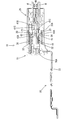
本発明の一実施形態を図1ないし図14を参照しつつ説明する。本実施形態に係るジョイントコネクタ10は、図示しない車両の車体に取り付けられて、複数のアース線W(本発明の構成である「電線」の一例)を接地するものである。以下の説明では、上下方向については図3を基準とし、図3の左方を前方、右方を後方として説明する。 <Embodiment>
An embodiment of the present invention will be described with reference to FIGS. The
ジョイントコネクタ10は、図3に示すように、各アース線Wの端末部に取り付けられた複数の端子金具20に電気的に接続されるとともに車体に取り付けられる金属製の導電部材30と、この導電部材30の雄タブ32側をインサート成形した合成樹脂製のハウジング35とを備える。 (Joint connector)
As shown in FIG. 3, the
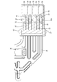
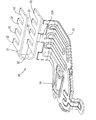
端子金具20は、雌型であって、図14に示すように、相手側の雄タブ32と接続される端子接続部21と、端子接続部21の後方に連なりアース線Wの端末部に接続される電線接続部26とを備える。 (Terminal bracket)
The
筒状部22は、弾性接触片25の基端部に連なる底壁22Aと、一対の側壁22Bと、弾性接触片25と対向する対向壁22Cとが環状に連なって構成されており、底壁22Aには、底壁22Aを矩形状に切欠いた被係止孔23が貫通形成されている。この被係止孔23は、その孔縁がランス43に係止されて端子金具20の抜けを防止する。被係止孔23の両脇には、端子金具20の誤挿入を防止するための板状のスタビライザー24が起立している。 The
The
電線接続部26は、電線の芯線部分を圧着するワイヤバレル部26Aと、ワイヤバレル部26Aの後方においてアース線Wに外嵌された防水ゴム栓27の上から挟持する挟持部26Bとからなる。 The
The electric
防水ゴム栓27は、円筒形状であって、アース線Wの外周が密着した状態で挿通されており、後方側の厚肉の部分の内周面及び外周面には、環状に突出するリップ部が軸方向に沿って複数設けられている。 As the ground wire W, an electric wire having a conductor portion covered with an insulating coating is used.
The
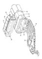
導電部材30は、金属板材を所定の形状にプレス加工してなり、ハウジング35にインサート成形されている。
導電部材30は、図12に示すように、U字状のタブ連結部31と、タブ連結部31の延びる方向に所定間隔毎に8個(複数個)設けられた雄タブ32と、タブ連結部31の下方に連なり車体に取り付けられる取付部33とを備えている。 (Conductive member)
The
As shown in FIG. 12, the
雄タブ32は、前後方向に延びる帯状Z(長方形の板状)をなし、端子金具20の弾性接触片25と弾性的に接触して端子金具20と導電部材30との間を電気的に接続する。
タブ連結部31の下段部分の中間部からは、下方に取付部33が延出されている。 The
The
A mounting
取付部33は、その前方側がやや側方側に曲がっている。取付部33には、取付孔34が貫通形成されており、この取付孔34内に、図示しないボルトが挿通されて、車体のねじ孔(図示せず)に螺合されることにより、取付部33が車体に固定される。 The
The front side of the mounting
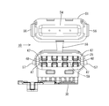
ハウジング35は、合成樹脂製であって、図7に示すように、左右方向に長い長円形の筒状の筒状周壁36の内部に、アース線Wの端末に接続された端子金具20が収容される8室(複数室)の収容室37が上下2段、幅方向に4列に等間隔で並んで設けられている。 (housing)
The
端子収容部40には、電線側隔壁39に連なる端子側隔壁41が設けられている。 The electric
The
検査用部材Tは、筒状周壁36の左右の最大内径寸法に応じた幅寸法(検査用部材挿入空間59の幅寸法。図4参照)を有する板状の部材である。 As shown in FIG. 8, the space extending horizontally from the bending
The inspection member T is a plate-like member having a width dimension (width dimension of the inspection
底壁41Bは、図8に示すように、電線収容部38の内壁(底壁)よりも厚肉に形成されており、この底壁41Bを共通の基端部として上下一対のランス43,43が前方に片持ち状に延びている。 When the
As shown in FIG. 8, the
係止突部43Aは、段差状に突出し、後方に向けて傾斜状に突出寸法が小さくなっている。 The
The locking
この撓み許容空間44の上下方向(撓み方向)の寸法A1は、一方のランス43のみの撓み変形を許容する寸法が設定されている。そのため、端子金具20の装着の際には、上下一対の端子金具20について、同時には装着せず、別々に装着する(複数の端子金具20を別々に後方から挿入してランス43,43に係止させる)。 A space between the pair of
The dimension A1 in the vertical direction (bending direction) of the bending
この縦連通空間45は、撓み許容空間44の前方側に撓み許容空間44と連なるように設けられている。 Here, the
The
これにより、ハウジング35における端子収容部40の前方側については、端子金具20の装着前においては、筒状周壁36の内面形状に応じた空間に雄タブ32が突出する構成となっている。 The cylindrical
Thereby, the front side of the
ガイド部46は、平行に配置され前後に延びる上下一対の突条47,47からなり、その略後半部分が撓み許容空間44の両側方に位置するように形成されている。溝部48の溝幅は、検査用部材Tを嵌め込んで摺動させることができる寸法に設定される。ガイド部46の溝部48に検査用部材Tの挿入方向における側縁部が嵌まり込むことにより、検査用部材Tが撓み許容空間44に案内される。 A
The
挿通部50の上下方向の隙間は、対向壁22Cの厚みよりもわずかに大きい一定の寸法に設定されている。これにより、アース線Wの端末に取り付けられた端子金具20が収容室37に挿入されると、雄タブ32が筒状部22内に進入し、弾性接触片25と弾性接触する。 The
The gap in the vertical direction of the
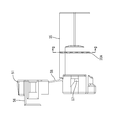
筒状周壁36の前端の開口部36Aは、図8に示すように、蓋部51で閉塞されるようなっている。
蓋部51は、ハウジング35の上壁のうち、前端部寄りの位置にヒンジ58を介して接続されており、開口部36Aを塞ぐ本体部52と、ハウジング35の前端部に外嵌する筒状カバー55とを備える。
本体部52には、ゴム栓装着部53が突出しており、このゴム栓装着部53にゴム栓54が外嵌される。 (Cover)
The
The
A rubber
筒状カバー55の左右には、図5に示すように、枠形のロック部56が設けられており、ハウジング35の外側面に突出形成されたロック受け部57に係止されて蓋部51をロック状態とする。 The
As shown in FIG. 5, frame-shaped
導電部材30をプレス機により打ち抜き加工、曲げ加工を行った後、金型内に固定してインサート成型する。次に、アース線Wの端末部に接続された端子金具20を、ハウジング35の後端部側から収容室37に挿入する。この端子金具20の挿入は、少なくとも上下一対の収容室37については、互いに異なるタイミングで装着する。そして、端子金具20がランス43に当接する位置まで挿入されると、ランス43が弾性変形し、更に押し込まれるとランス43の係止突部43Aが端子接続部21の被係止孔23内に達し、ランス43が復帰変形し、係止突部43Aが被係止孔23内に配される。これにより、端子金具20が後方に引っ張られても、係止突部43Aが被係止孔23の孔縁に係止されるため、端子金具20の抜け止めが図られる。
このようにして全ての端子金具20をハウジング35に装着する。 Next, assembly of the
The
In this way, all the
このとき、ランス43の係止突部43Aが端子接続部21の被係止孔23内に配されていれば、ランス43が弾性変形後に正常に復元変形しているため、一対のランス43,43の基端側に当接する位置まで検査用部材Tを挿入することができる。 In the inspection of the state of the
At this time, if the locking
(1)車両の複数のアース線W(電線)の端末部に取り付けられた複数の端子金具を電気的に接続するジョイントコネクタ10であって、一対の端子金具20,20を保持する一対の端子保持部49A,49Aを備え、一対の端子保持部49A,49A間には、一対の端子金具20,20に係止して一対の端子金具20,20の抜けを抑制する互いに撓み変形可能な一対のランス43,43が、撓み許容空間44を介して互いに背き合う姿勢で配置されている。 According to the said embodiment, there exist the following effects.
(1) A
このようにすれば、一対の端子保持部49A,49A内の空間を連通する縦連通空間45が形成されているため、縦連通空間45の部分に隔壁等を設けて上下一対の端子保持部49A,49A間を分断する場合と比較してジョイントコネクタ10の構成を簡素化することができる。 (2) A vertical communication space 45 (communication space) that communicates the space in the pair of
In this way, since the
このようにすれば、一対のランス43,43の突出する方向の構成を簡素化することができる。 (3) The vertical communication space 45 (communication space) is provided in the direction in which the pair of
In this way, the configuration in the protruding direction of the pair of
このようにすれば、縦連通空間45と撓み許容空間44との間が隔壁等により分断されている場合と比較して、ジョイントコネクタ10の構成を簡素化することができる。 (4) The vertical communication space 45 (communication space) is continuous with the bending
In this way, the configuration of the
このようにすれば、縦連通空間45及び撓み許容空間44に検査用部材Tを挿入してランス43,43の係止状態の検査をすることができる。 (5) An inspection member T for inspecting the locked state of the
If it does in this way, the inspection member T can be inserted in the
このようにすれば、検査用部材Tを、ハウジング35の開口部36Aから挿入して検査用部材挿入空間59を通して撓み許容空間44及び横連通空間42(連通空間)まで挿入することで一対のランス43,43の係止状態の検査をすることが可能になる。 (7) The pair of
By doing so, the inspection member T is inserted from the
このようにすれば、全ての撓み許容空間44及び横連通空間42(連通空間)に挿通可能な検査用部材Tを用いることにより、全ての端子金具20,20についてランス43,43の係止状態の検査を一括して行うことが可能になる。 (8) The lateral communication space 42 (communication space) is provided between all adjacent holding portion pairs 49.
In this way, by using the inspection member T that can be inserted into all the
このようにすれば、ランス43,43の係止状態の検査に用いられる検査用部材Tを容易に所定位置まで挿入することが可能になる。 (9) A
In this way, it becomes possible to easily insert the inspection member T used for the inspection of the locked state of the
このようにすれば、アース線Wの取り外し等の際に破断溝35Aによりハウジング35を破断させる作業が容易になる。また、本実施形態のように、ハウジング35に横連通空間42(連通空間)が設けられる構成において破断溝35Aを設けることにより、隔壁が少ない分だけ破断溝35Aから破断させる作業を容易にすることができる。 (10) The pair of
This facilitates the work of breaking the
このようにすれば、たとえ一対の端子保持部49A,49A内の空間を連通する連通空間45を設けた場合でも、アース線Wの端子金具20間については、電圧が印加されるものではなく絶縁破壊等を考慮する必要がないため、発明の実施態様として好適なものとすることができる。 (11) The electric wire is the ground wire W, and is the
In this way, even when the
本発明は上記記述及び図面によって説明した実施形態に限定されるものではなく、例えば次のような実施形態も本発明の技術的範囲に含まれる。
(1)上記実施形態では、8本のアース線Wに接続された8個の端子金具20を接地する構成としたが、これに限られず、2個~7個、又は9個以上のアース線Wに接続された2個~7個、又は9個以上の端子金具20を接地する構成としてもよい。 <Other embodiments>
The present invention is not limited to the embodiments described with reference to the above description and drawings. For example, the following embodiments are also included in the technical scope of the present invention.
(1) In the above embodiment, the eight
(3)上記実施形態では、端子金具20は、雌形としたが、これに限らず、雄形の端子金具を用いるようにしてもよい。また、導電部材30側についても、雄タブ32に代えて雌型の端子を用いてもよい。 (2) Although the
(3) In the above embodiment, the terminal fitting 20 is female, but the present invention is not limited to this, and a male terminal fitting may be used. Further, on the
(5)上記実施形態では、ランス43,43は前方に向かって延びる形態であったが、これに限られず、ランスを後方へ延びる形態としてもよい。この場合、ランスの撓み許容空間は、後方側に形成されることになる。 (4) In the above embodiment, the
(5) In the said embodiment, although the
(7)上記実施形態では、全ての一対の端子保持部49A,49A(全ての隣り合う保持部対49間)について、撓み許容空間44及び横連通空間42を設ける構成としたが、これに限られず、一部の隣り合う保持部対49間について撓み許容空間44や横連通空間42を設けるようにしてもよい。 (6) In the said embodiment, although the partition was provided so that the electric
(7) In the above embodiment, all the pair of
20…端子金具
21…端子接続部
22…筒状部
23…被係止孔
25…弾性接触片
30…導電部材
32…雄タブ
33…取付部
35…ハウジング
35A…破断溝
36…筒状周壁
36A…開口部
37…収容室
38…電線収容部
39…電線側隔壁
40…端子収容部
41…端子側隔壁
41B…底壁
42…横連通空間(連通空間)
43,43…一対のランス
43A…係止突部
44…撓み許容空間
45…縦連通空間(連通空間)
46…ガイド部
47…突条
48…溝部
49A…端子保持部
49…保持部対
50…挿通部
51…蓋部
54…ゴム栓
59…検査用部材挿入空間
T…検査用部材
W…アース線(電線) DESCRIPTION OF
43, 43 ... Pair of
46 ...
Claims (11)
- 車両の複数の電線の端末部に取り付けられた複数の端子金具を電気的に接続するジョイントコネクタであって、
一対の前記端子金具を保持する一対の端子保持部を備え、
前記一対の端子保持部間には、前記一対の端子金具に係止して前記一対の端子金具の抜けを抑制する互いに撓み変形可能な一対のランスが、撓み許容空間を介して互いに背き合う姿勢で配置されているジョイントコネクタ。 A joint connector for electrically connecting a plurality of terminal fittings attached to terminal portions of a plurality of electric wires of a vehicle,
A pair of terminal holding portions for holding the pair of terminal fittings;
Between the pair of terminal holding portions, a pair of lances that can bend and deform so as to be locked to the pair of terminal fittings and prevent the pair of terminal fittings from coming out of each other are opposed to each other via a bending allowance space. Joint connector arranged in. - 前記一対の端子保持部内の空間を連通する連通空間が形成されている請求項1記載のジョイントコネクタ。 The joint connector according to claim 1, wherein a communication space that communicates the space in the pair of terminal holding portions is formed.
- 前記連通空間は、前記一対のランスの突出する方向に設けられている請求項2に記載のジョイントコネクタ。 The joint connector according to claim 2, wherein the communication space is provided in a direction in which the pair of lances protrudes.
- 前記連通空間は、前記撓み許容空間に連なっている請求項2又は請求項3に記載のジョイントコネクタ。 The joint connector according to claim 2, wherein the communication space is continuous with the bending allowable space.
- 前記連通空間及び前記撓み許容空間には、前記ランスの係止状態の検査のための検査用部材を挿入可能となっている請求項2ないし請求項4のいずれか一項に記載のジョイントコネクタ。 The joint connector according to any one of claims 2 to 4, wherein an inspection member for inspecting a locked state of the lance can be inserted into the communication space and the bending allowance space.
- 前記一対の端子保持部からなる保持部対は、複数並列に配置されており、
前記並列に配置された複数の保持部対のうち隣り合う前記保持部対の間には、隣り合う前記撓み許容空間を連通する連通空間が設けられている請求項1に記載のジョイントコネクタ。 A plurality of holding part pairs composed of the pair of terminal holding parts are arranged in parallel,
2. The joint connector according to claim 1, wherein a communication space is provided between the adjacent holding portion pairs among the plurality of holding portion pairs arranged in parallel. - 前記一対のランスは、ハウジングに設けられており、
前記ハウジングには、前記一対のランスの係止状態の検査のための検査用部材を挿入可能な開口部が設けられるとともに、前記開口部から前記撓み許容空間及び前記連通空間に連なる検査用部材挿入空間が設けられている請求項6記載のジョイントコネクタ。 The pair of lances are provided in the housing,
The housing is provided with an opening into which an inspection member for inspecting the locked state of the pair of lances can be inserted, and the inspection member inserted from the opening to the bending-permissible space and the communication space The joint connector according to claim 6, wherein a space is provided. - 前記連通空間は、全ての前記隣り合う保持部対間に設けられている請求項7記載のジョイントコネクタ。 The joint connector according to claim 7, wherein the communication space is provided between all the adjacent holding portion pairs.
- 前記検査用部材の挿入方向の側縁部を案内するガイド部が設けられている請求項8に記載のジョイントコネクタ。 The joint connector according to claim 8, wherein a guide portion that guides a side edge portion in the insertion direction of the inspection member is provided.
- 前記一対のランスは、ハウジングに設けられており、
前記ハウジングの外周面には、前記ハウジングを破断させる破断溝が設けられている請求項2ないし請求項9のいずれか一項に記載のジョイントコネクタ。 The pair of lances are provided in the housing,
The joint connector according to any one of claims 2 to 9, wherein a fracture groove for breaking the housing is provided on an outer peripheral surface of the housing. - 前記電線は、アース線であり、前記複数の端子金具に電気的に接続される導電部材が車体に取り付けられてアースされる請求項2ないし請求項10のいずれか一項に記載のジョイントコネクタ。 The joint connector according to any one of claims 2 to 10, wherein the electric wire is a ground wire, and a conductive member electrically connected to the plurality of terminal fittings is attached to the vehicle body and grounded.
Priority Applications (3)
| Application Number | Priority Date | Filing Date | Title |
|---|---|---|---|
| US14/347,896 US9362665B2 (en) | 2011-09-29 | 2012-09-10 | Joint connector with pairs of locking lances and communication space extending between the pairs of locking lances |
| CN201280047449.2A CN103843208B (en) | 2011-09-29 | 2012-09-11 | Joint connector |
| DE112012004084.8T DE112012004084T5 (en) | 2011-09-29 | 2012-09-11 | coupling connector |
Applications Claiming Priority (4)
| Application Number | Priority Date | Filing Date | Title |
|---|---|---|---|
| JP2011-214384 | 2011-09-29 | ||
| JP2011214384A JP5720518B2 (en) | 2011-09-29 | 2011-09-29 | Joint connector |
| JP2011214386A JP5692600B2 (en) | 2011-09-29 | 2011-09-29 | Joint connector |
| JP2011-214386 | 2011-09-29 |
Publications (1)
| Publication Number | Publication Date |
|---|---|
| WO2013047178A1 true WO2013047178A1 (en) | 2013-04-04 |
Family
ID=47995216
Family Applications (1)
| Application Number | Title | Priority Date | Filing Date |
|---|---|---|---|
| PCT/JP2012/073126 WO2013047178A1 (en) | 2011-09-29 | 2012-09-11 | Joint connector |
Country Status (4)
| Country | Link |
|---|---|
| US (1) | US9362665B2 (en) |
| CN (1) | CN103843208B (en) |
| DE (1) | DE112012004084T5 (en) |
| WO (1) | WO2013047178A1 (en) |
Families Citing this family (13)
| Publication number | Priority date | Publication date | Assignee | Title |
|---|---|---|---|---|
| JP5743740B2 (en) * | 2011-06-23 | 2015-07-01 | 矢崎総業株式会社 | connector |
| JP6141612B2 (en) * | 2012-09-21 | 2017-06-07 | 矢崎総業株式会社 | connector |
| JP5772810B2 (en) * | 2012-12-27 | 2015-09-02 | 住友電装株式会社 | Joint connector |
| DE102014202316B4 (en) * | 2014-02-07 | 2021-04-01 | Te Connectivity Germany Gmbh | Contact carrier with a base body and at least one contact element, tool for injection molding a contact carrier and method for producing a contact carrier |
| JP6259417B2 (en) * | 2014-09-25 | 2018-01-10 | 矢崎総業株式会社 | Terminal bracket and connection structure of terminal bracket |
| JP6206392B2 (en) * | 2014-12-25 | 2017-10-04 | 株式会社オートネットワーク技術研究所 | Joint connector |
| JP6295230B2 (en) * | 2015-04-30 | 2018-03-14 | 矢崎総業株式会社 | Connector and manufacturing method thereof |
| JP6334456B2 (en) * | 2015-04-30 | 2018-05-30 | 矢崎総業株式会社 | Connector and manufacturing method thereof |
| KR101755856B1 (en) * | 2015-10-06 | 2017-07-19 | 현대자동차주식회사 | Multi earth Connector For Vehicle |
| US9653859B1 (en) * | 2016-04-11 | 2017-05-16 | Delphi Technologies, Inc. | Electrical connector system |
| KR20210070115A (en) * | 2019-12-04 | 2021-06-14 | 현대자동차주식회사 | Connector |
| DE102020204456A1 (en) * | 2020-04-07 | 2021-10-07 | Te Connectivity Germany Gmbh | Connection arrangement |
| US11837806B2 (en) * | 2020-12-09 | 2023-12-05 | Lear Corporation | Grounding electrical connector |
Citations (8)
| Publication number | Priority date | Publication date | Assignee | Title |
|---|---|---|---|---|
| JPH02160385A (en) * | 1988-12-13 | 1990-06-20 | Riyousei Denso Kk | Connector housing |
| JPH08250185A (en) * | 1995-01-13 | 1996-09-27 | Sumitomo Wiring Syst Ltd | Joint connector and cap therefor |
| JP2000058181A (en) * | 1998-08-07 | 2000-02-25 | Sumitomo Wiring Syst Ltd | Connector |
| JP2000077140A (en) * | 1998-08-27 | 2000-03-14 | Sumitomo Wiring Syst Ltd | Installing structure of ground joint connector and grounding terminal metal fitting |
| JP2010040263A (en) * | 2008-08-01 | 2010-02-18 | Autonetworks Technologies Ltd | Joint connector and method of connecting terminal to terminal using the joint connector |
| JP2011060522A (en) * | 2009-09-08 | 2011-03-24 | Autonetworks Technologies Ltd | Grounding joint-connector and wire harness including the same |
| JP2011103192A (en) * | 2009-11-10 | 2011-05-26 | Sumitomo Wiring Syst Ltd | Joint connector and wire harness |
| JP2011103193A (en) * | 2009-11-10 | 2011-05-26 | Sumitomo Wiring Syst Ltd | Joint connector and wire harness |
Family Cites Families (10)
| Publication number | Priority date | Publication date | Assignee | Title |
|---|---|---|---|---|
| US3325769A (en) * | 1964-09-25 | 1967-06-13 | Rogers Corp | Separable electrical circuit assembly |
| US4067637A (en) * | 1976-12-09 | 1978-01-10 | Thomas & Betts Corporation | Electrical connector |
| US5769650A (en) | 1995-06-19 | 1998-06-23 | Sumitomo Wiring Systems, Ltd. | Connector and cover therefor |
| JP4019638B2 (en) * | 2001-01-29 | 2007-12-12 | 住友電装株式会社 | connector |
| US6599150B1 (en) * | 2002-03-22 | 2003-07-29 | Tyco Electronics Corporation | Electrical connector assembly |
| FR2867313A1 (en) * | 2004-03-04 | 2005-09-09 | Framatome Connectors Int | Electrical connector housing, has set of sockets, each including strip that forms stop, where each strip connects two opposite lateral walls of socket adjacent to transversal walls |
| WO2006108610A1 (en) * | 2005-04-11 | 2006-10-19 | Fci | Electrical connector |
| US7387545B2 (en) * | 2006-03-24 | 2008-06-17 | Fci Americas Technology, Inc. | Electrical connector with pre-locked terminal position assurance (TPA) |
| JP5670763B2 (en) * | 2011-01-12 | 2015-02-18 | 矢崎総業株式会社 | Terminal locking structure |
| JP5668655B2 (en) * | 2011-09-20 | 2015-02-12 | 株式会社オートネットワーク技術研究所 | Conductive plate and joint connector |
-
2012
- 2012-09-10 US US14/347,896 patent/US9362665B2/en active Active
- 2012-09-11 WO PCT/JP2012/073126 patent/WO2013047178A1/en active Application Filing
- 2012-09-11 DE DE112012004084.8T patent/DE112012004084T5/en not_active Withdrawn
- 2012-09-11 CN CN201280047449.2A patent/CN103843208B/en not_active Expired - Fee Related
Patent Citations (8)
| Publication number | Priority date | Publication date | Assignee | Title |
|---|---|---|---|---|
| JPH02160385A (en) * | 1988-12-13 | 1990-06-20 | Riyousei Denso Kk | Connector housing |
| JPH08250185A (en) * | 1995-01-13 | 1996-09-27 | Sumitomo Wiring Syst Ltd | Joint connector and cap therefor |
| JP2000058181A (en) * | 1998-08-07 | 2000-02-25 | Sumitomo Wiring Syst Ltd | Connector |
| JP2000077140A (en) * | 1998-08-27 | 2000-03-14 | Sumitomo Wiring Syst Ltd | Installing structure of ground joint connector and grounding terminal metal fitting |
| JP2010040263A (en) * | 2008-08-01 | 2010-02-18 | Autonetworks Technologies Ltd | Joint connector and method of connecting terminal to terminal using the joint connector |
| JP2011060522A (en) * | 2009-09-08 | 2011-03-24 | Autonetworks Technologies Ltd | Grounding joint-connector and wire harness including the same |
| JP2011103192A (en) * | 2009-11-10 | 2011-05-26 | Sumitomo Wiring Syst Ltd | Joint connector and wire harness |
| JP2011103193A (en) * | 2009-11-10 | 2011-05-26 | Sumitomo Wiring Syst Ltd | Joint connector and wire harness |
Also Published As
| Publication number | Publication date |
|---|---|
| DE112012004084T5 (en) | 2014-07-24 |
| CN103843208B (en) | 2016-07-13 |
| CN103843208A (en) | 2014-06-04 |
| US20140235090A1 (en) | 2014-08-21 |
| US9362665B2 (en) | 2016-06-07 |
Similar Documents
| Publication | Publication Date | Title |
|---|---|---|
| WO2013047178A1 (en) | Joint connector | |
| JP5563241B2 (en) | Electrical connector | |
| US9124024B2 (en) | Connector having inner conductive member | |
| US9209582B2 (en) | Connector | |
| US8608508B2 (en) | Rubber plug and waterproof connector | |
| CN109845047B (en) | Connector structure | |
| JP2019024013A (en) | Terminal and electrical connector with the same | |
| US9444172B2 (en) | Connector | |
| US7413478B2 (en) | Electric contact for contacting a protecting conductor with conductive housing | |
| TWI525941B (en) | Connector | |
| US9379475B2 (en) | Electric connector | |
| JP2011243581A (en) | Connector terminal and connector with connector terminal | |
| US10290966B2 (en) | Joint connector | |
| US9583873B2 (en) | Electrical connector having detecting structure | |
| JP4837025B2 (en) | Plug housing and electric plug for driving power transmission | |
| US10116084B2 (en) | Connector | |
| CN113826283A (en) | Connecting device and connector | |
| JP5720518B2 (en) | Joint connector | |
| JP5692600B2 (en) | Joint connector | |
| JP4871628B2 (en) | connector | |
| EP3020096B1 (en) | Improved connector assembly with mat seal | |
| KR101758673B1 (en) | Connector assembly | |
| US20100136814A1 (en) | Packing and connector having the same | |
| KR20210070116A (en) | Joint connector | |
| JP2020030987A (en) | Connector and connector assembly |
Legal Events
| Date | Code | Title | Description |
|---|---|---|---|
| 121 | Ep: the epo has been informed by wipo that ep was designated in this application |
Ref document number: 12837047 Country of ref document: EP Kind code of ref document: A1 |
|
| WWE | Wipo information: entry into national phase |
Ref document number: 14347896 Country of ref document: US |
|
| WWE | Wipo information: entry into national phase |
Ref document number: 1120120040848 Country of ref document: DE Ref document number: 112012004084 Country of ref document: DE |
|
| 122 | Ep: pct application non-entry in european phase |
Ref document number: 12837047 Country of ref document: EP Kind code of ref document: A1 |