WO2013047138A1 - Chain guide and chain drive device - Google Patents
Chain guide and chain drive device Download PDFInfo
- Publication number
- WO2013047138A1 WO2013047138A1 PCT/JP2012/072708 JP2012072708W WO2013047138A1 WO 2013047138 A1 WO2013047138 A1 WO 2013047138A1 JP 2012072708 W JP2012072708 W JP 2012072708W WO 2013047138 A1 WO2013047138 A1 WO 2013047138A1
- Authority
- WO
- WIPO (PCT)
- Prior art keywords
- chain
- roller
- guide
- rollers
- chain guide
- Prior art date
Links
Images


Classifications
-
- F—MECHANICAL ENGINEERING; LIGHTING; HEATING; WEAPONS; BLASTING
- F16—ENGINEERING ELEMENTS AND UNITS; GENERAL MEASURES FOR PRODUCING AND MAINTAINING EFFECTIVE FUNCTIONING OF MACHINES OR INSTALLATIONS; THERMAL INSULATION IN GENERAL
- F16H—GEARING
- F16H7/00—Gearings for conveying rotary motion by endless flexible members
- F16H7/08—Means for varying tension of belts, ropes, or chains
- F16H7/10—Means for varying tension of belts, ropes, or chains by adjusting the axis of a pulley
- F16H7/12—Means for varying tension of belts, ropes, or chains by adjusting the axis of a pulley of an idle pulley
-
- F—MECHANICAL ENGINEERING; LIGHTING; HEATING; WEAPONS; BLASTING
- F16—ENGINEERING ELEMENTS AND UNITS; GENERAL MEASURES FOR PRODUCING AND MAINTAINING EFFECTIVE FUNCTIONING OF MACHINES OR INSTALLATIONS; THERMAL INSULATION IN GENERAL
- F16H—GEARING
- F16H7/00—Gearings for conveying rotary motion by endless flexible members
- F16H7/18—Means for guiding or supporting belts, ropes, or chains
-
- F—MECHANICAL ENGINEERING; LIGHTING; HEATING; WEAPONS; BLASTING
- F16—ENGINEERING ELEMENTS AND UNITS; GENERAL MEASURES FOR PRODUCING AND MAINTAINING EFFECTIVE FUNCTIONING OF MACHINES OR INSTALLATIONS; THERMAL INSULATION IN GENERAL
- F16H—GEARING
- F16H7/00—Gearings for conveying rotary motion by endless flexible members
- F16H7/06—Gearings for conveying rotary motion by endless flexible members with chains
-
- F—MECHANICAL ENGINEERING; LIGHTING; HEATING; WEAPONS; BLASTING
- F16—ENGINEERING ELEMENTS AND UNITS; GENERAL MEASURES FOR PRODUCING AND MAINTAINING EFFECTIVE FUNCTIONING OF MACHINES OR INSTALLATIONS; THERMAL INSULATION IN GENERAL
- F16H—GEARING
- F16H7/00—Gearings for conveying rotary motion by endless flexible members
- F16H7/08—Means for varying tension of belts, ropes, or chains
- F16H2007/0842—Mounting or support of tensioner
-
- F—MECHANICAL ENGINEERING; LIGHTING; HEATING; WEAPONS; BLASTING
- F16—ENGINEERING ELEMENTS AND UNITS; GENERAL MEASURES FOR PRODUCING AND MAINTAINING EFFECTIVE FUNCTIONING OF MACHINES OR INSTALLATIONS; THERMAL INSULATION IN GENERAL
- F16H—GEARING
- F16H7/00—Gearings for conveying rotary motion by endless flexible members
- F16H7/08—Means for varying tension of belts, ropes, or chains
- F16H2007/0863—Finally actuated members, e.g. constructional details thereof
- F16H2007/0865—Pulleys
-
- F—MECHANICAL ENGINEERING; LIGHTING; HEATING; WEAPONS; BLASTING
- F16—ENGINEERING ELEMENTS AND UNITS; GENERAL MEASURES FOR PRODUCING AND MAINTAINING EFFECTIVE FUNCTIONING OF MACHINES OR INSTALLATIONS; THERMAL INSULATION IN GENERAL
- F16H—GEARING
- F16H7/00—Gearings for conveying rotary motion by endless flexible members
- F16H7/08—Means for varying tension of belts, ropes, or chains
- F16H7/10—Means for varying tension of belts, ropes, or chains by adjusting the axis of a pulley
- F16H7/12—Means for varying tension of belts, ropes, or chains by adjusting the axis of a pulley of an idle pulley
- F16H7/1254—Means for varying tension of belts, ropes, or chains by adjusting the axis of a pulley of an idle pulley without vibration damping means
- F16H7/1281—Means for varying tension of belts, ropes, or chains by adjusting the axis of a pulley of an idle pulley without vibration damping means where the axis of the pulley moves along a substantially circular path
-
- F—MECHANICAL ENGINEERING; LIGHTING; HEATING; WEAPONS; BLASTING
- F16—ENGINEERING ELEMENTS AND UNITS; GENERAL MEASURES FOR PRODUCING AND MAINTAINING EFFECTIVE FUNCTIONING OF MACHINES OR INSTALLATIONS; THERMAL INSULATION IN GENERAL
- F16H—GEARING
- F16H7/00—Gearings for conveying rotary motion by endless flexible members
- F16H7/18—Means for guiding or supporting belts, ropes, or chains
- F16H7/20—Mountings for rollers or pulleys
Definitions
- the present invention relates to a chain guide for guiding the traveling of a torque transmission chain and a chain transmission device using the chain guide.
- the automobile engine transmits the rotation of the crankshaft to the camshaft via a timing chain (hereinafter simply referred to as “chain”), and opens and closes the combustion chamber valve by the rotation of the camshaft.
- chain a timing chain
- a camshaft drive chain transmission device As such a camshaft drive chain transmission device, a drive sprocket attached to a crankshaft, a driven sprocket attached to the camshaft, a chain spanned between the drive sprocket and the driven sprocket, and the chain A swingable chain guide disposed on the slack side, a chain tensioner that presses the chain guide toward the chain, and a fixed chain guide disposed on the tension side of the chain are often used.
- the chain guide on the swing side keeps the chain tension constant by pressing the chain with the urging force of the chain tensioner, and the chain guide on the fixed side keeps the ideal chain travel line while maintaining the chain's tension. Suppresses vibration.
- the inventors of the present invention have proposed a chain guide in which a plurality of rollers are provided at intervals along the chain traveling direction and the chain is guided by each of the rollers (patent). Reference 1).
- This chain guide is characterized by low chain running resistance and low torque transmission loss because the chain contact is rolling contact.
- the inventors of the present invention span a chain between a drive sprocket attached to a crankshaft and a driven sprocket attached to a camshaft.
- a test machine that guides the running of the machine with a rolling chain guide was manufactured, and an endurance test was performed in which the crankshaft of the test machine was rotated in the red zone.
- each roller of the chain guide can be used without being damaged, and it was confirmed that it has durability enough to withstand practical use.
- scaly peeling flaking
- the roller shaft and rollers that support the roller may occur on the roller shaft and rollers that support the roller, and there is a certain tendency in the distribution of the roller shaft that causes this peeling. I found it.
- a guide base that is swingably supported around the end on the camshaft side, and that the end on the crankshaft side is pressed by a chain guide, and the guide base is spaced along the chain traveling direction.
- the inventors of the present invention have investigated the cause of such a tendency by variously changing the test conditions, and found that the following two points are the dominant causes.
- 1) The radius of a virtual arc that passes through the center of each roller and the center of the roller adjacent to both sides of the roller decreases from the camshaft side end of the guide base toward the crankshaft end.
- the problem to be solved by the present invention is to provide a chain guide having excellent durability.
- a guide base that is arranged on a part of the outer periphery of the torque transmission chain and extends long in the traveling direction of the chain, and a distance along the traveling direction of the chain between the guide base and the guide base.
- a chain guide composed of a plurality of roller shafts attached to each other and rollers supported rotatably on the respective roller shafts, the distance between the centers of the rollers is set so as to become narrower in a region where the load on the rollers is larger. did.
- each roller When arranging each roller such that the radius of a virtual arc that passes through the center of each roller and the center of the roller adjacent to both sides of the roller in common decreases from one end of the guide base toward the other end, The load applied to the roller becomes larger as the radius of the virtual arc is smaller. Further, when the guide base is supported to be swingable around one end portion of the guide base and the other end portion is pressed by a chain tensioner, the load applied to the roller is closer to the end portion on the side pressed by the chain tensioner. growing.
- each roller shaft supporting the roller is a solid cylindrical body that is brightly quenched.
- the rollers may have only a part of the rollers at unequal intervals and the rest at equal intervals. However, when all the rollers are arranged at unequal intervals, the load applied to each roller can be more effectively distributed. Is possible.
- the chain spanned between the drive sprocket and the driven sprocket, and the swingable chain guide provided on the slack side of the chain And a chain transmission having a chain tensioner that presses the chain guide toward the chain.
- the greater the load applied to the roller the narrower the distance between the centers of the rollers, so that the load applied to each roller is made uniform and exhibits excellent durability.
- FIG. 2 Schematic which shows the chain transmission of embodiment of this invention 1 is a perspective view of the chain guide shown in FIG. 2 is a longitudinal sectional view of the chain guide shown in FIG. Right side view of the chain guide shown in FIG. Sectional view along line VV in FIG.
- FIG. 5 is an enlarged sectional view of the roller shown in FIG. Exploded front view showing part of guide base and rollers
- A is a schematic diagram showing a virtual arc that commonly passes through the center of the second roller from the cam shaft side shown in FIG. 1 and the centers of the rollers adjacent to both sides of the roller, and (b) in FIG.
- the schematic diagram which shows the virtual arc which passes along the center of the 3rd roller from the cam shaft side to show, and the center of the roller adjacent to the both sides of the roller in common
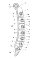
- FIG. 1 shows a chain transmission device incorporating a chain guide according to an embodiment of the present invention.
- This chain transmission device spans between a drive sprocket 2 fixedly attached to a crankshaft 1 of an engine, a driven sprocket 4 fixedly attached to a camshaft 3, and the drive sprocket 2 and the driven sprocket 4.
- the rotation of the crankshaft 1 is transmitted to the camshaft 3 through the chain 5, and the combustion chamber valve (not shown) is opened and closed by the rotation of the camshaft 3.
- the rotation direction of the crankshaft 1 is constant (right rotation in the figure).
- the chain 5 is stretched on the side that is pulled into the drive sprocket 2 as the crankshaft 1 rotates.
- the portion on the side that is fed from the drive sprocket 2 is the slack side.
- a fixed chain guide 9 is provided on the tension side of the chain 5.
- the chain guide 7 extends long along the chain 5, and a fulcrum shaft 6 is inserted into an insertion hole 10 provided at the end of the camshaft 3, and is supported so as to be swingable about the fulcrum shaft 6. .
- a chain tensioner 8 is in contact with the end of the chain guide 7 on the crankshaft 1 side, and the chain guide 7 is pressed toward the chain 5 by the chain tensioner 8.
- the fixed-side chain guide 9 also has a shape that extends long along the chain 5 in the same manner as the swing-side chain guide 7.
- the chain guide 9 on the fixed side is fixed by tightening the bolts 14 by inserting bolts 14 into insertion holes 13 provided at the end on the camshaft 3 side and the end on the crankshaft 1 side, respectively.
- the chain guide 7 includes a guide base 15 extending in the traveling direction of the chain 5 and a plurality of rollers attached to the guide base 15 at intervals along the traveling direction of the chain 5.
- the shaft 16 includes a roller 17 rotatably supported on each roller shaft 16.
- an insertion hole 10 is provided at one end of the guide base 15 (the end on the camshaft 3 side shown in FIG. 1), and the other end of the guide base 15 (the crankshaft 1 shown in FIG. 1).
- a receiving portion 15a is provided at the end of the side.
- the guide base 15 is supported so as to be swingable about the fulcrum shaft 6 inserted into the insertion hole 10, and the receiving portion 15 a is pressed by the chain tensioner 8.
- the guide base 15 extends in the running direction of the chain 5 and supports a pair of opposed side plates 18 and 18 that support both ends of each roller shaft 16, and adjacent roller shafts 16. It has the some connection part 19 which is arrange
- the shaft introduction groove 21 is formed in a tapered shape in which the groove width gradually decreases from the convex edge of the side plate 18 toward the circular recess 20, and the shaft of the roller shaft 16 passes through the shaft introduction groove 21.
- the end is introduced into the circular recess 20.
- the width D 1 of the narrow portion of the shaft introducing groove 21 is the inner diameter D of the circular recessed portion 20. It is formed to be smaller than 2 .
- the inner diameter D 2 of the circular recess 20 is slightly smaller in diameter than the outer diameter d of the shaft end of the roller shaft 16 is adapted to fit into the circular recess 20 with interference the axial end of the roller shaft 16.
- the guide base 15 can be formed by injection molding of a synthetic resin containing a fiber reinforcement.
- a synthetic resin for example, polyamide (PA) such as nylon 66 or nylon 46 can be used. Glass fiber, carbon fiber, aramid fiber, etc. can be used as the fiber reinforcing material blended in the synthetic resin.
- the guide base 15 may be formed of a light metal such as an aluminum alloy or a magnesium alloy.
- the roller shaft 16 is a solid cylindrical body formed of a steel material such as SUJ2 or SC material, and is brightly quenched to improve the wear resistance of the surface.
- the roller 17 is rotatably mounted on the outer periphery of the roller shaft 16, and a cylindrical surface formed on the outer periphery of the roller 17 is in contact with the chain 5.
- the roller 17 is a roller bearing including an outer ring 22, a plurality of rollers 23 incorporated inside the outer ring 22, and a cage 24 that holds these rollers 23.
- the outer ring 22 is a shell-shaped outer ring formed into a cup shape by drawing a steel plate such as SPC or SCM. Inward flanges 25 are formed at both ends of the outer ring 22.
- the outer diameter of the outer ring 22 is set in the range of 10 mm to 25 mm, and the outer diameters of all the outer rings 22 are the same.
- the roller bearing is used alone as the roller 17 in order to reduce the weight of the roller 17 and minimize the running resistance of the chain 5, but a cylindrical resin is formed on the outer periphery of the outer ring 22 of the roller bearing.
- a member attached with a member or an iron member may be used as the roller 17, and other types of bearings may be used instead of the roller bearings.
- the roller bearing refers to a cylindrical roller bearing and a needle roller bearing.
- Each roller 17 shown in FIG. 1 has a radius of a virtual arc that passes through the center of each roller 17 and the centers of rollers 17 and 17 adjacent to both sides of the roller 17 on the cam shaft 3 side of the guide base 15. It arrange
- Each roller 17 has a smaller center-to-center distance in a region where the radius of a virtual arc that passes through the center of each roller 17 and the centers of rollers 17 and 17 adjacent to both sides of the roller 17 is smaller.
- rollers 17 1 , 17 2 , 17 3 , 17 4 ,... are arranged in order from the cam shaft 3 side toward the crankshaft 1 side. The arrangement will be specifically described.
- center O 3 of the virtual circle a 3 through 4 of the central commonly is in a different position, when comparing the radius R 2, R 3 of the two virtual circle a 2, a 3, the cam shaft 3 side than the radius R 2 of the virtual circle a 2, rollers 17 1 to 17 4 as it is smaller radius R 3 of the virtual circle R 3 of the crank shaft 1 side is disposed.
- the other rollers 17 4 to 17 6 similarly have virtual arcs A 4 to A that pass through the center of the roller 17 and the centers of two rollers 17 and 17 adjacent to both sides of the roller 17 in common.
- the radius R 4 ⁇ R 6 of these virtual circle a 4 ⁇ a 6 are the rollers 17 3-17 7 so as to decrease toward the crank shaft 1 side from the cam shaft 3 side arrangement Has been.
- the center of the roller 17 and the centers of the two rollers 17 and 17 adjacent to both sides of the roller 17 are common to all the rollers 17 2 to 17 6 except the rollers 17 1 and 17 7 at both ends.
- virtual circle a 2 ⁇ radius R 2 ⁇ R 6 are the rollers 17 1-17 7 so as to decrease toward the crank shaft 1 side from the cam shaft 3 side of the a 6 through Te are disposed.
- the radius R 2 ⁇ R 6 is smaller toward the crank shaft 1 side from the cam shaft 3 side, in the radial R 2 ⁇ R 6, towards the crank shaft 1 side from the cam shaft 3 side size
- the rollers 17 1 to 17 4 are arranged. Specifically, the distance between the centers of rollers 17 1, 17 2 D 12, the distance between the centers of the rollers 17 2, 17 3 D 23, the roller 17 3, 17 4 of the center distance is taken as D 34 , D 12 + D 23 > D 23 + D 34 The distances D 12 , D 23 and D 34 between the centers of the rollers 17 1 to 17 4 are set so that the above relationship is established.
- roller 17 4-17 7 Similarly, the center-to-center distance, the more area radius R 4 ⁇ R 6 of virtual circle A 4 ⁇ A 6 is small, the area rollers 17 4-17 7 The rollers 17 4 to 17 7 are arranged so that the distance between the centers becomes narrow.
- each roller 17 closer to the receiving portion 15a of the guide base 15 pressed by the chain tensioner 8 (the crankshaft 1 side) is more. Further, it is closer to the point of action of the pressing force of the chain tensioner 8 than the roller 17 on the side farther from the receiving portion 15a (camshaft 3 side), and the load applied to the roller 17 from the chain tensioner 8 tends to increase. Also from this point, in order to make the load applied to each roller 17 uniform, each roller 17 moves from the roller 17 on the side farther from the receiving portion 15a of the guide base 15 pressed by the chain tensioner 8 toward the roller 17 on the closer side. It is preferable to arrange the rollers 17 so that the center-to-center distance is narrow.
- the fixed-side chain guide 9 also has a plurality of rollers 33 provided at intervals along the traveling direction of the chain 5, similar to the swing-side chain guide 7.
- the rollers 33 are arranged at equal intervals.
- the chain 5 travels between the drive sprocket 2 and the driven sprocket 4, and torque is transmitted from the crankshaft 1 to the camshaft 3 by the chain 5.
- the swing-side chain guide 7 keeps the tension of the chain 5 constant by pressing the chain 5 with the urging force of the chain tensioner 8, and the fixed-side chain guide 9 is used to run the ideal chain 5. The vibration of the chain 5 is suppressed while keeping the line.
- each roller 17 of the chain guide 7 rotates while contacting the edge on the back side of each frame constituting the chain 5, and the contact between the chain 5 and the chain guide 7 is a rolling contact, so that the running resistance of the chain 5 is reduced. Small, low torque transmission loss.
- the distance between the centers of the rollers 17 is narrower in the region where the load applied to the rollers 17 is larger (that is, the region closer to the crankshaft 1), so the load applied to each roller 17 is made uniform. Therefore, the life of the roller shaft 16 that supports each roller 17 can be extended as a whole, and excellent durability is exhibited.
- a silent chain As the chain 5 for transmitting the rotation of the crankshaft 1 to the camshaft 3, a silent chain, a roller chain, a bush chain in which a roller is omitted from the roller chain, or the like can be used.
Abstract
Provided is a chain guide of superior durability. A chain guide obtained from guide bases (15) that are disposed on a portion of the outer circumference of a torque transmission chain (5) and extend longitudinally in the direction of travel of said chain (5), multiple roller shafts (16) installed on the guide bases (15) at intervals along the direction of travel of the chain (5), and rollers (17) that are rotatably supported on each roller shaft (16), wherein the distances between the centers of the respective rollers (17) are set to be shorter in the region where the load on the roller (17) is higher.
Description
この発明は、トルク伝達用チェーンの走行を案内するチェーンガイドおよびそのチェーンガイドを用いたチェーン伝動装置に関する。
The present invention relates to a chain guide for guiding the traveling of a torque transmission chain and a chain transmission device using the chain guide.
自動車エンジンは、クランク軸の回転をタイミングチェーン(以下、単に「チェーン」という)を介してカム軸に伝達し、そのカム軸の回転により燃焼室のバルブを開閉する。
The automobile engine transmits the rotation of the crankshaft to the camshaft via a timing chain (hereinafter simply referred to as “chain”), and opens and closes the combustion chamber valve by the rotation of the camshaft.
このようなカム軸駆動用のチェーン伝動装置として、クランク軸に取り付けられた駆動スプロケットと、カム軸に取り付けられた従動スプロケットと、駆動スプロケットと従動スプロケットの間に掛け渡されたチェーンと、そのチェーンの弛み側に配置された揺動可能なチェーンガイドと、そのチェーンガイドをチェーンに向けて押圧するチェーンテンショナと、チェーンの張り側に配置された固定のチェーンガイドとを有するものが多く用いられる。
As such a camshaft drive chain transmission device, a drive sprocket attached to a crankshaft, a driven sprocket attached to the camshaft, a chain spanned between the drive sprocket and the driven sprocket, and the chain A swingable chain guide disposed on the slack side, a chain tensioner that presses the chain guide toward the chain, and a fixed chain guide disposed on the tension side of the chain are often used.
ここで、揺動側のチェーンガイドは、チェーンテンショナの付勢力でチェーンを押圧することによりチェーンの張力を一定に保ち、固定側のチェーンガイドは、理想的なチェーンの走行ラインを保ちながらチェーンの振動を抑制する。
Here, the chain guide on the swing side keeps the chain tension constant by pressing the chain with the urging force of the chain tensioner, and the chain guide on the fixed side keeps the ideal chain travel line while maintaining the chain's tension. Suppresses vibration.
かかるチェーン伝動装置で使用される揺動側のチェーンガイドや固定側のチェーンガイドとして、チェーン走行方向に沿って延びる案内面をチェーンに滑り接触させる形式のものが知られているが、この滑り形式のチェーンガイドは、チェーンに対する接触が滑り接触なので、チェーンの走行抵抗が大きく、トルクの伝達ロスが大きいという問題がある。
As a swing side chain guide and a fixed side chain guide used in such a chain transmission device, there is known a type in which a guide surface extending along the chain traveling direction is in sliding contact with the chain. However, the chain guide has a problem that the running resistance of the chain is large and the torque transmission loss is large since the contact with the chain is a sliding contact.
このような問題を解消するため、本願発明の発明者らは、チェーン走行方向に沿って間隔をおいて複数のローラを設け、その各ローラでチェーンを案内するチェーンガイドを提案している(特許文献1)。
In order to solve such a problem, the inventors of the present invention have proposed a chain guide in which a plurality of rollers are provided at intervals along the chain traveling direction and the chain is guided by each of the rollers (patent). Reference 1).
このチェーンガイドは、チェーンに対する接触が転がり接触なので、チェーンの走行抵抗が小さく、トルクの伝達ロスが小さいという特徴がある。
This chain guide is characterized by low chain running resistance and low torque transmission loss because the chain contact is rolling contact.
ところで、この発明の発明者らは、上記転がり形式のチェーンガイドの耐久性を評価するために、クランク軸に取り付けた駆動スプロケットとカム軸に取り付けた従動スプロケットの間にチェーンを掛け渡し、そのチェーンの走行を転がり形式のチェーンガイドで案内する試験機を製作し、その試験機のクランク軸をレッドゾーンで回転させる耐久試験を行なった。
By the way, in order to evaluate the durability of the above-described chain guide, the inventors of the present invention span a chain between a drive sprocket attached to a crankshaft and a driven sprocket attached to a camshaft. A test machine that guides the running of the machine with a rolling chain guide was manufactured, and an endurance test was performed in which the crankshaft of the test machine was rotated in the red zone.
この結果、レッドゾーンで数千時間を経過した後も、チェーンガイドの各ローラが損傷せずに使用することができ、実用に耐える程度の耐久性を有することを確認することができたが、更に長時間にわたって耐久試験を継続したところ、ローラを支持するローラ軸やころにうろこ状の剥離(フレーキング)が生じる場合があり、この剥離が生じるローラ軸の分布に一定の傾向があることを見出した。
As a result, even after passing thousands of hours in the red zone, each roller of the chain guide can be used without being damaged, and it was confirmed that it has durability enough to withstand practical use. When the durability test is continued for a long time, scaly peeling (flaking) may occur on the roller shaft and rollers that support the roller, and there is a certain tendency in the distribution of the roller shaft that causes this peeling. I found it.
すなわち、カム軸側の端部を中心として揺動可能に支持され、かつ、クランク軸側の端部がチェーンガイドで押圧されるガイドベースと、そのガイドベースにチェーンの走行方向に沿って間隔をおいて取り付けられた複数のローラ軸と、その各ローラ軸に回転可能に支持されたローラとからなるチェーンガイドを使用して耐久試験を行なったところ、このチェーンガイドがローラ軸の剥離によって寿命に達するとき、ガイドベースにチェーンの走行方向に沿って間隔をおいて取り付けられた各ローラ軸のうち、カム軸側の領域のローラ軸ではなく、クランク軸側の領域のローラ軸に剥離が生じる傾向があることが分かった。
That is, a guide base that is swingably supported around the end on the camshaft side, and that the end on the crankshaft side is pressed by a chain guide, and the guide base is spaced along the chain traveling direction. When a durability test was conducted using a chain guide consisting of a plurality of roller shafts mounted on the roller shaft and rollers rotatably supported by the roller shafts, Among the roller shafts attached to the guide base at intervals along the running direction of the chain, the roller shaft in the region on the crankshaft side tends to peel rather than the roller shaft in the region on the camshaft side. I found out that
そして、本願発明の発明者らは、試験条件を様々に変更してかかる傾向が生じる原因を究明したところ、以下の2点が支配的な原因となっていることを見出した。
1)各ローラの中心とそのローラの両側に隣り合うローラの中心とを共通して通る仮想円弧の半径が、ガイドベースのカム軸側の端部からクランク軸側の端部に向かうに従って小さくなるように前記各ローラを配置することにより、クランク軸のスプロケットに対するチェーンの巻き角をできるだけ大きくし、クランク軸のスプロケットの1歯あたりの負荷を抑えることが可能となる。そして、このように各ローラを配置した場合、各ローラの中心とそのローラの両側に隣り合うローラの中心とを共通して通る仮想円弧の半径が小さい領域(すなわちクランク軸側の領域)においては、チェーンの走行方向の曲がりが大きいため、チェーンからローラにかかる負荷が大きくなりやすい点。
2)ガイドベースのチェーンテンショナで押圧される側の端部に近い領域のローラの方が、ガイドベースの揺動中心がある側の端部に近い領域のローラよりも、チェーンテンショナの押圧力の作用点に近く、チェーンテンショナからローラにかかる負荷が大きくなりやすい点。 The inventors of the present invention have investigated the cause of such a tendency by variously changing the test conditions, and found that the following two points are the dominant causes.
1) The radius of a virtual arc that passes through the center of each roller and the center of the roller adjacent to both sides of the roller decreases from the camshaft side end of the guide base toward the crankshaft end. By arranging the rollers in this manner, the winding angle of the chain with respect to the crankshaft sprocket can be made as large as possible, and the load per tooth of the crankshaft sprocket can be suppressed. And when each roller is arranged in this way, in the region where the radius of the virtual arc passing through the center of each roller and the center of the roller adjacent to both sides of the roller is small (ie, the region on the crankshaft side)・ Because the bend in the running direction of the chain is large, the load on the roller from the chain tends to increase.
2) The roller in the region closer to the end of the guide base that is pressed by the chain tensioner has a lower pressing force of the chain tensioner than the roller in the region closer to the end of the guide base that has the swing center. It is close to the point of action and the load on the roller from the chain tensioner tends to increase.
この発明が解決しようとする課題は、優れた耐久性をもつチェーンガイドを提供することである。
The problem to be solved by the present invention is to provide a chain guide having excellent durability.
上記課題を解決するため、この発明では、トルク伝達用チェーンの外周一部に配置されて、そのチェーンの走行方向に長く延びるガイドベースと、そのガイドベースにチェーンの走行方向に沿って間隔をおいて取り付けられた複数のローラ軸と、その各ローラ軸に回転可能に支持されたローラとからなるチェーンガイドにおいて、前記各ローラの中心間距離をローラにかかる負荷が大きい領域ほど狭くなるように設定した。
In order to solve the above-described problems, in the present invention, a guide base that is arranged on a part of the outer periphery of the torque transmission chain and extends long in the traveling direction of the chain, and a distance along the traveling direction of the chain between the guide base and the guide base. In a chain guide composed of a plurality of roller shafts attached to each other and rollers supported rotatably on the respective roller shafts, the distance between the centers of the rollers is set so as to become narrower in a region where the load on the rollers is larger. did.
このようにすると、ローラにかかる負荷が大きい領域ほどローラの中心間距離が狭いので、各ローラにかかる負荷が均一化される。そのため、ローラを支持するローラ軸の寿命を全体として延ばすことができ、優れた耐久性をもつチェーンガイドが得ることができる。
In this case, since the distance between the centers of the rollers is narrower in a region where the load applied to the rollers is larger, the load applied to each roller is made uniform. Therefore, the life of the roller shaft that supports the roller can be extended as a whole, and a chain guide having excellent durability can be obtained.
各ローラの中心とそのローラの両側に隣り合うローラの中心とを共通して通る仮想円弧の半径がガイドベースの一端部から他端部に向かうに従って小さくなるように前記各ローラを配置する場合、前記仮想円弧の半径が小さい領域ほど前記ローラにかかる負荷が大きくなる。また、前記ガイドベースの一端部を中心として揺動可能に支持し、他端部をチェーンテンショナで押圧する場合、前記チェーンテンショナで押圧される側の端部に近い領域ほど前記ローラにかかる負荷が大きくなる。
When arranging each roller such that the radius of a virtual arc that passes through the center of each roller and the center of the roller adjacent to both sides of the roller in common decreases from one end of the guide base toward the other end, The load applied to the roller becomes larger as the radius of the virtual arc is smaller. Further, when the guide base is supported to be swingable around one end portion of the guide base and the other end portion is pressed by a chain tensioner, the load applied to the roller is closer to the end portion on the side pressed by the chain tensioner. growing.
また、前記ローラを支持する各ローラ軸は、光輝焼入れされた中実の円柱体とすると好ましい。
Further, it is preferable that each roller shaft supporting the roller is a solid cylindrical body that is brightly quenched.
前記ローラは、その一部のローラのみを不等間隔とし、残りを等間隔としてもよいが、全部の前記ローラを不等間隔に配置すると、各ローラにかかる負荷をより効果的に分散することが可能となる。
The rollers may have only a part of the rollers at unequal intervals and the rest at equal intervals. However, when all the rollers are arranged at unequal intervals, the load applied to each roller can be more effectively distributed. Is possible.
また、この発明では、上記のチェーンガイドを用いたチェーン伝動装置として、駆動スプロケットと従動スプロケットの間に掛け渡されたチェーンと、そのチェーンの弛み側に設けられた揺動可能な上記のチェーンガイドと、そのチェーンガイドをチェーンに向けて押圧するチェーンテンショナとを有するチェーン伝動装置を提供する。
Further, in the present invention, as a chain transmission device using the above chain guide, the chain spanned between the drive sprocket and the driven sprocket, and the swingable chain guide provided on the slack side of the chain And a chain transmission having a chain tensioner that presses the chain guide toward the chain.
この発明のチェーンガイドは、ローラにかかる負荷が大きい領域ほどローラの中心間距離が狭いので、各ローラにかかる負荷が均一化され、優れた耐久性を発揮する。
In the chain guide of the present invention, the greater the load applied to the roller, the narrower the distance between the centers of the rollers, so that the load applied to each roller is made uniform and exhibits excellent durability.
図1に、この発明の実施形態のチェーンガイドを組み込んだチェーン伝動装置を示す。このチェーン伝動装置は、エンジンのクランク軸1に固定して取り付けられた駆動スプロケット2と、カム軸3に固定して取り付けられた従動スプロケット4と、駆動スプロケット2と従動スプロケット4の間に掛け渡されたチェーン5を有し、このチェーン5を介してクランク軸1の回転をカム軸3に伝達し、そのカム軸3の回転により燃焼室のバルブ(図示せず)を開閉する。
FIG. 1 shows a chain transmission device incorporating a chain guide according to an embodiment of the present invention. This chain transmission device spans between a drive sprocket 2 fixedly attached to a crankshaft 1 of an engine, a driven sprocket 4 fixedly attached to a camshaft 3, and the drive sprocket 2 and the driven sprocket 4. The rotation of the crankshaft 1 is transmitted to the camshaft 3 through the chain 5, and the combustion chamber valve (not shown) is opened and closed by the rotation of the camshaft 3.
エンジンが作動しているときのクランク軸1の回転方向は一定(図では右回転)であり、このときチェーン5は、クランク軸1の回転に伴って駆動スプロケット2に引き込まれる側の部分が張り側となり、駆動スプロケット2から送り出される側の部分が弛み側となる。そして、チェーン5の弛み側には、支点軸6を中心として揺動可能に支持されたチェーンガイド7と、チェーンガイド7をチェーン5に向けて押圧するチェーンテンショナ8とが設けられている。一方、チェーン5の張り側には、固定のチェーンガイド9が設けられている。
When the engine is operating, the rotation direction of the crankshaft 1 is constant (right rotation in the figure). At this time, the chain 5 is stretched on the side that is pulled into the drive sprocket 2 as the crankshaft 1 rotates. The portion on the side that is fed from the drive sprocket 2 is the slack side. On the slack side of the chain 5, there are provided a chain guide 7 that is swingably supported around the fulcrum shaft 6 and a chain tensioner 8 that presses the chain guide 7 toward the chain 5. On the other hand, a fixed chain guide 9 is provided on the tension side of the chain 5.
チェーンガイド7は、チェーン5に沿って長く延び、そのカム軸3側の端部に設けた挿入孔10に支点軸6が挿入され、この支点軸6を中心に揺動可能に支持されている。チェーンガイド7のクランク軸1側の端部にはチェーンテンショナ8が接触しており、このチェーンテンショナ8によってチェーンガイド7はチェーン5に向けて押圧されている。
The chain guide 7 extends long along the chain 5, and a fulcrum shaft 6 is inserted into an insertion hole 10 provided at the end of the camshaft 3, and is supported so as to be swingable about the fulcrum shaft 6. . A chain tensioner 8 is in contact with the end of the chain guide 7 on the crankshaft 1 side, and the chain guide 7 is pressed toward the chain 5 by the chain tensioner 8.
固定側のチェーンガイド9も、揺動側のチェーンガイド7と同様に、チェーン5に沿って長く延びる形状である。固定側のチェーンガイド9は、カム軸3側の端部とクランク軸1側の端部にそれぞれ設けられた挿入孔13にボルト14が挿入され、このボルト14の締め付けによって固定されている。
The fixed-side chain guide 9 also has a shape that extends long along the chain 5 in the same manner as the swing-side chain guide 7. The chain guide 9 on the fixed side is fixed by tightening the bolts 14 by inserting bolts 14 into insertion holes 13 provided at the end on the camshaft 3 side and the end on the crankshaft 1 side, respectively.
図2~図4に示すように、チェーンガイド7は、チェーン5の走行方向に延びるガイドベース15と、そのガイドベース15にチェーン5の走行方向に沿って間隔をおいて取り付けられた複数のローラ軸16と、その各ローラ軸16に回転可能に支持されたローラ17とからなる。
As shown in FIGS. 2 to 4, the chain guide 7 includes a guide base 15 extending in the traveling direction of the chain 5 and a plurality of rollers attached to the guide base 15 at intervals along the traveling direction of the chain 5. The shaft 16 includes a roller 17 rotatably supported on each roller shaft 16.
図3に示すように、ガイドベース15の一端部(図1に示すカム軸3側の端部)には挿入孔10が設けられ、ガイドベース15の他端部(図1に示すクランク軸1側の端部)には受け部15aが設けられている。このガイドベース15は、図1に示すように、挿入孔10に挿入した支点軸6を中心として揺動可能に支持され、受け部15aがチェーンテンショナ8で押圧される。
As shown in FIG. 3, an insertion hole 10 is provided at one end of the guide base 15 (the end on the camshaft 3 side shown in FIG. 1), and the other end of the guide base 15 (the crankshaft 1 shown in FIG. 1). A receiving portion 15a is provided at the end of the side. As shown in FIG. 1, the guide base 15 is supported so as to be swingable about the fulcrum shaft 6 inserted into the insertion hole 10, and the receiving portion 15 a is pressed by the chain tensioner 8.
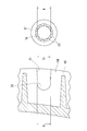
図2、図4に示すように、ガイドベース15は、チェーン5の走行方向に沿って長く延びて各ローラ軸16の両端を支持する対向一対の側板18,18と、隣り合うローラ軸16の間に配置されて側板18同士を連結する複数の連結部19とを有する。連結部19は、その両端が側板18に固定され、側板18の対向間隔を保持している。図3および図7に示すように、各側板18の互いに対向する対向面には、ローラ軸16の軸端を支持する円形凹部20と、側板18の凸側の縁から円形凹部20に連通する軸導入溝21とが設けられている。
As shown in FIGS. 2 and 4, the guide base 15 extends in the running direction of the chain 5 and supports a pair of opposed side plates 18 and 18 that support both ends of each roller shaft 16, and adjacent roller shafts 16. It has the some connection part 19 which is arrange | positioned between and connects the side plates 18 mutually. Both ends of the connecting portion 19 are fixed to the side plate 18, and the facing interval of the side plate 18 is maintained. As shown in FIG. 3 and FIG. 7, the opposing surfaces of each side plate 18 communicate with the circular recess 20 that supports the shaft end of the roller shaft 16, and the circular recess 20 communicates from the convex edge of the side plate 18. A shaft introduction groove 21 is provided.
図7に示すように、軸導入溝21は、側板18の凸側の縁から円形凹部20に向かって次第に溝幅が狭くなるテーパ状に形成され、この軸導入溝21を通じてローラ軸16の軸端を円形凹部20に導入するようになっている。ここで、円形凹部20内に導入されたローラ軸16の軸端が軸導入溝21に逆戻りするのを防止するため、軸導入溝21は、狭小部分の幅D1が円形凹部20の内径D2よりも小さくなるよう形成されている。
As shown in FIG. 7, the shaft introduction groove 21 is formed in a tapered shape in which the groove width gradually decreases from the convex edge of the side plate 18 toward the circular recess 20, and the shaft of the roller shaft 16 passes through the shaft introduction groove 21. The end is introduced into the circular recess 20. Here, in order to prevent the shaft end of the roller shaft 16 introduced into the circular recessed portion 20 from returning to the shaft introducing groove 21, the width D 1 of the narrow portion of the shaft introducing groove 21 is the inner diameter D of the circular recessed portion 20. It is formed to be smaller than 2 .
円形凹部20の内径D2は、ローラ軸16の軸端の外径dよりもわずかに小径とされ、ローラ軸16の軸端が締め代をもって円形凹部20に嵌合するようになっている。
The inner diameter D 2 of the circular recess 20 is slightly smaller in diameter than the outer diameter d of the shaft end of the roller shaft 16 is adapted to fit into the circular recess 20 with interference the axial end of the roller shaft 16.
ガイドベース15は、繊維強化材を配合した合成樹脂の射出成形により形成することができる。合成樹脂としては、例えば、ナイロン66やナイロン46などのポリアミド(PA)を使用することができる。合成樹脂に配合する繊維強化材は、ガラス繊維、カーボン繊維、アラミド繊維などを使用することができる。ガイドベース15はアルミニウム合金やマグネシウム合金等の軽金属で形成してもよい。
The guide base 15 can be formed by injection molding of a synthetic resin containing a fiber reinforcement. As the synthetic resin, for example, polyamide (PA) such as nylon 66 or nylon 46 can be used. Glass fiber, carbon fiber, aramid fiber, etc. can be used as the fiber reinforcing material blended in the synthetic resin. The guide base 15 may be formed of a light metal such as an aluminum alloy or a magnesium alloy.
ローラ軸16は、SUJ2やSC材等の鋼材で形成された中実の円柱体であり、表面の耐摩耗性を向上させるために光輝焼入れが施されている。
The roller shaft 16 is a solid cylindrical body formed of a steel material such as SUJ2 or SC material, and is brightly quenched to improve the wear resistance of the surface.
図5、図6に示すように、ローラ17は、ローラ軸16の外周に回転可能に装着され、ローラ17の外周に形成された円筒面がチェーン5と接触する。ここで、ローラ17は、外輪22と、外輪22の内側に組み込まれた複数のころ23と、これらのころ23を保持する保持器24とからなるころ軸受である。外輪22は、SPCやSCM等の鋼板を絞り成形してカップ状とされたシェル形外輪である。外輪22の両端には、内向きの鍔25が形成されている。外輪22の外径は10mm~25mmの範囲に設定されており、全ての外輪22の外径が同一の大きさとされている。
5 and 6, the roller 17 is rotatably mounted on the outer periphery of the roller shaft 16, and a cylindrical surface formed on the outer periphery of the roller 17 is in contact with the chain 5. Here, the roller 17 is a roller bearing including an outer ring 22, a plurality of rollers 23 incorporated inside the outer ring 22, and a cage 24 that holds these rollers 23. The outer ring 22 is a shell-shaped outer ring formed into a cup shape by drawing a steel plate such as SPC or SCM. Inward flanges 25 are formed at both ends of the outer ring 22. The outer diameter of the outer ring 22 is set in the range of 10 mm to 25 mm, and the outer diameters of all the outer rings 22 are the same.
なお、この実施形態では、ローラ17を軽量化してチェーン5の走行抵抗を最小限に抑えるためにころ軸受を単独でローラ17として用いているが、ころ軸受の外輪22の外周に円筒状の樹脂部材や鉄部材を取り付けたものをローラ17として用いてもよく、ころ軸受にかえて他の形式の軸受を用いることも可能である。ここで、ころ軸受とは、円筒ころ軸受および針状ころ軸受をいう。
In this embodiment, the roller bearing is used alone as the roller 17 in order to reduce the weight of the roller 17 and minimize the running resistance of the chain 5, but a cylindrical resin is formed on the outer periphery of the outer ring 22 of the roller bearing. A member attached with a member or an iron member may be used as the roller 17, and other types of bearings may be used instead of the roller bearings. Here, the roller bearing refers to a cylindrical roller bearing and a needle roller bearing.
図1に示す各ローラ17は、各ローラ17の中心とそのローラ17の両側に隣り合うローラ17,17の中心とを共通して通る仮想円弧の半径が、ガイドベース15のカム軸3側の端部からクランク軸1側の端部に向かうに従って小さくなるように配置されている。また、各ローラ17は、各ローラ17の中心とそのローラ17の両側に隣り合うローラ17,17の中心とを共通して通る仮想円弧の半径が小さい領域ほどローラ17の中心間距離が狭くなるように配置されている。
Each roller 17 shown in FIG. 1 has a radius of a virtual arc that passes through the center of each roller 17 and the centers of rollers 17 and 17 adjacent to both sides of the roller 17 on the cam shaft 3 side of the guide base 15. It arrange | positions so that it may become small as it goes to the edge part by the side of the crankshaft 1 from an edge part. Each roller 17 has a smaller center-to-center distance in a region where the radius of a virtual arc that passes through the center of each roller 17 and the centers of rollers 17 and 17 adjacent to both sides of the roller 17 is smaller. Are arranged as follows.
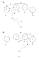
以下、図8(a)および(b)に示すように、各ローラ17をカム軸3側からクランク軸1側に向かって順にローラ171,172,173,174,・・・と称してその配置を具体的に説明する。
8 (a) and 8 (b), the rollers 17 1 , 17 2 , 17 3 , 17 4 ,... Are arranged in order from the cam shaft 3 side toward the crankshaft 1 side. The arrangement will be specifically described.
図8(a)に示すように、ローラ172の中心と、そのローラ172の両側に隣り合う2つのローラ171,173の中心とを共通して通る仮想円弧A2を想定する。次に、図8(b)に示すように、ローラ173の中心と、そのローラ173の両側に隣り合う2つのローラ172,174の中心とを共通して通る仮想円弧A3を想定する。そうすると、図8(a)に示すローラ171,172,173の中心を共通して通る仮想円弧A2の中心O2と、図8(b)に示すローラ172,173,174の中心を共通して通る仮想円弧A3の中心O3は異なる位置にあり、この2つの仮想円弧A2,A3の半径R2,R3を比較したときに、カム軸3側の仮想円弧A2の半径R2よりも、クランク軸1側の仮想円弧R3の半径R3の方が小さくなるようにローラ171~174が配置されている。
As shown in FIG. 8 (a), assuming the center of the roller 17 2, a virtual circle A 2 passing in common with the center of the roller 17 of the two which 2 adjacent each side roller 17 1, 17 3. Next, as shown in FIG. 8 (b), the center of the roller 17 3, a virtual circle A 3 passing in common with the center of the roller 17 of the two adjacent on each side of the third roller 17 2, 17 4 Suppose. Then, the center O 2 of the virtual arc A 2 that commonly passes through the centers of the rollers 17 1 , 17 2 , and 17 3 shown in FIG. 8A and the rollers 17 2 , 17 3 , and 17 shown in FIG. center O 3 of the virtual circle a 3 through 4 of the central commonly is in a different position, when comparing the radius R 2, R 3 of the two virtual circle a 2, a 3, the cam shaft 3 side than the radius R 2 of the virtual circle a 2, rollers 17 1 to 17 4 as it is smaller radius R 3 of the virtual circle R 3 of the crank shaft 1 side is disposed.
図示しないが、他のローラ174~176についても同様に、ローラ17の中心と、そのローラ17の両側に隣り合う2つのローラ17,17の中心とを共通して通る仮想円弧A4~A6を想定した場合、これらの仮想円弧A4~A6の半径R4~R6が、カム軸3側からクランク軸1側に向かうに従って小さくなるように各ローラ173~177が配置されている。
Although not shown, the other rollers 17 4 to 17 6 similarly have virtual arcs A 4 to A that pass through the center of the roller 17 and the centers of two rollers 17 and 17 adjacent to both sides of the roller 17 in common. assuming the a 6, the radius R 4 ~ R 6 of these virtual circle a 4 ~ a 6 are the rollers 17 3-17 7 so as to decrease toward the crank shaft 1 side from the cam shaft 3 side arrangement Has been.
このように、両端のローラ171、177を除く全てのローラ172~176について、ローラ17の中心と、そのローラ17の両側に隣り合う2つのローラ17,17の中心とを共通して通る仮想円弧A2~A6の半径R2~R6がカム軸3側からクランク軸1側に向かうに従って小さくなるように各ローラ171~177が配置されている。
As described above, the center of the roller 17 and the centers of the two rollers 17 and 17 adjacent to both sides of the roller 17 are common to all the rollers 17 2 to 17 6 except the rollers 17 1 and 17 7 at both ends. virtual circle a 2 ~ radius R 2 ~ R 6 are the rollers 17 1-17 7 so as to decrease toward the crank shaft 1 side from the cam shaft 3 side of the a 6 through Te are disposed.
ここで、半径R2~R6がカム軸3側からクランク軸1側に向かうに従って小さくなるとは、半径R2~R6の中に、カム軸3側からクランク軸1側に向かって大きさが変化しないものが含まれていてもよく、その他の半径R2~R6が、カム軸3側からクランク軸1側に向かって小さくなっていれば足りる。
Here, the radius R 2 ~ R 6 is smaller toward the crank shaft 1 side from the cam shaft 3 side, in the radial R 2 ~ R 6, towards the crank shaft 1 side from the cam shaft 3 side size However, it is sufficient that the other radii R 2 to R 6 become smaller from the camshaft 3 side toward the crankshaft 1 side.
このように、仮想円弧A2~A6の半径R2~R6が、ガイドベース15のカム軸3側の端部からクランク軸1側の端部に向かうに従って小さくなるように各ローラ171~177を配置することにより、図1に示すクランク軸1のスプロケット2に対するチェーン5の巻き角をできるだけ大きくし、クランク軸1のスプロケット2の1歯あたりの負荷を抑えることが可能となる。
In this way, each of the rollers 17 1 so that the radii R 2 to R 6 of the virtual arcs A 2 to A 6 decrease from the end on the camshaft 3 side of the guide base 15 toward the end on the crankshaft 1 side. by placing the ~ 17 7, as large as possible a winding angle of the chain 5 with respect to the sprocket 2 of the crankshaft 1 shown in FIG. 1, it is possible to suppress the load per tooth of the sprocket 2 of the crankshaft 1.
ところで、図8(a)および(b)に示す各ローラ171~174に案内されてチェーン5が走行するとき、図8(a)に示すローラ171,172,173の領域よりも、図8(b)に示すローラ172,173,174の領域の方が、チェーン5の走行方向の曲がりが大きい。そのため、チェーン5からローラ172にかかる負荷よりも、チェーン5からローラ173にかかる負荷の方が大きくなりやすい。
By the way, when the chain 5 travels while being guided by the rollers 17 1 to 17 4 shown in FIGS. 8A and 8B, the region of the rollers 17 1 , 17 2 , and 17 3 shown in FIG. However, the region of the rollers 17 2 , 17 3 , and 17 4 shown in FIG. Therefore, than the load exerted from the chain 5 to the roller 17 2, it tends to increase towards the load applied from the chain 5 to the roller 17 3.
そこで、各ローラ171~174にかかる負荷を均一化するため、ローラ172,173,174の中心間距離が、ローラ171,172,173の中心間距離よりも狭くなるように各ローラ171~174が配置されている。具体的には、ローラ171,172の中心間距離をD12、ローラ172,173の中心間距離をD23、ローラ173,174の中心間距離をD34としたときに、
D12+D23>D23+D34
の関係が成立するように各ローラ171~174の中心間距離D12、D23、D34が設定されている。 In order to equalize the load on eachroller 17 1 to 17 4, the distance between the centers of the rollers 17 2, 17 3, 17 4, narrower than the distance between the centers of the roller 17 1, 17 2, 17 3 Thus, the rollers 17 1 to 17 4 are arranged. Specifically, the distance between the centers of rollers 17 1, 17 2 D 12, the distance between the centers of the rollers 17 2, 17 3 D 23, the roller 17 3, 17 4 of the center distance is taken as D 34 ,
D 12 + D 23 > D 23 + D 34
The distances D 12 , D 23 and D 34 between the centers of therollers 17 1 to 17 4 are set so that the above relationship is established.
D12+D23>D23+D34
の関係が成立するように各ローラ171~174の中心間距離D12、D23、D34が設定されている。 In order to equalize the load on each
D 12 + D 23 > D 23 + D 34
The distances D 12 , D 23 and D 34 between the centers of the
図示しないが、他のローラ174~177の中心間距離についても同様に、仮想円弧A4~A6の半径R4~R6が小さい領域ほど、その領域のローラ174~177の中心間距離が狭くなるように各ローラ174~177が配置されている。
Although not shown, the other roller 17 4-17 7 Similarly, the center-to-center distance, the more area radius R 4 ~ R 6 of virtual circle A 4 ~ A 6 is small, the area rollers 17 4-17 7 The rollers 17 4 to 17 7 are arranged so that the distance between the centers becomes narrow.
また、図1に示す各ローラ17とチェーンテンショナ8の相対位置関係に着目すると、チェーンテンショナ8で押圧されるガイドベース15の受け部15aに近い側(クランク軸1側)のローラ17の方が、受け部15aから遠い側(カム軸3側)のローラ17よりも、チェーンテンショナ8の押圧力の作用点に近く、チェーンテンショナ8からローラ17にかかる負荷が大きくなりやすい。この点からも、各ローラ17にかかる負荷を均一化するため、チェーンテンショナ8で押圧されるガイドベース15の受け部15aから遠い側のローラ17から近い側のローラ17に向かうに従って、各ローラ17の中心間距離が狭くなるようにローラ17を配置すると好ましい。
When attention is paid to the relative positional relationship between each roller 17 and the chain tensioner 8 shown in FIG. 1, the roller 17 closer to the receiving portion 15a of the guide base 15 pressed by the chain tensioner 8 (the crankshaft 1 side) is more. Further, it is closer to the point of action of the pressing force of the chain tensioner 8 than the roller 17 on the side farther from the receiving portion 15a (camshaft 3 side), and the load applied to the roller 17 from the chain tensioner 8 tends to increase. Also from this point, in order to make the load applied to each roller 17 uniform, each roller 17 moves from the roller 17 on the side farther from the receiving portion 15a of the guide base 15 pressed by the chain tensioner 8 toward the roller 17 on the closer side. It is preferable to arrange the rollers 17 so that the center-to-center distance is narrow.
図1に示すように、固定側のチェーンガイド9も、揺動側のチェーンガイド7と同様に、チェーン5の走行方向に沿って間隔をおいて設けられた複数のローラ33を有するが、このローラ33は等間隔に配置されている。
As shown in FIG. 1, the fixed-side chain guide 9 also has a plurality of rollers 33 provided at intervals along the traveling direction of the chain 5, similar to the swing-side chain guide 7. The rollers 33 are arranged at equal intervals.
次に、上記構成からなるチェーン伝動装置の動作例を説明する。
Next, an operation example of the chain transmission device configured as described above will be described.
エンジンが作動しているとき、駆動スプロケット2と従動スプロケット4の間でチェーン5が走行し、そのチェーン5によってクランク軸1からカム軸3にトルクが伝達される。このとき、揺動側のチェーンガイド7は、チェーンテンショナ8の付勢力でチェーン5を押圧することによりチェーン5の張力を一定に保ち、固定側のチェーンガイド9は、理想的なチェーン5の走行ラインを保ちながらチェーン5の振動を抑制する。
When the engine is operating, the chain 5 travels between the drive sprocket 2 and the driven sprocket 4, and torque is transmitted from the crankshaft 1 to the camshaft 3 by the chain 5. At this time, the swing-side chain guide 7 keeps the tension of the chain 5 constant by pressing the chain 5 with the urging force of the chain tensioner 8, and the fixed-side chain guide 9 is used to run the ideal chain 5. The vibration of the chain 5 is suppressed while keeping the line.
ここで、チェーンガイド7の各ローラ17は、チェーン5を構成する各コマの背部側の縁に接触しながら回転し、チェーン5とチェーンガイド7の接触が転がり接触なので、チェーン5の走行抵抗が小さく、トルクの伝達ロスが小さい。
Here, each roller 17 of the chain guide 7 rotates while contacting the edge on the back side of each frame constituting the chain 5, and the contact between the chain 5 and the chain guide 7 is a rolling contact, so that the running resistance of the chain 5 is reduced. Small, low torque transmission loss.
この実施形態のチェーンガイド7は、ローラ17にかかる負荷が大きい領域(すなわちクランク軸1に近い領域)ほどローラ17の中心間距離が狭いので、各ローラ17にかかる負荷が均一化される。そのため、各ローラ17を支持するローラ軸16の寿命を全体として延ばすことができ、優れた耐久性を発揮する。
In the chain guide 7 of this embodiment, the distance between the centers of the rollers 17 is narrower in the region where the load applied to the rollers 17 is larger (that is, the region closer to the crankshaft 1), so the load applied to each roller 17 is made uniform. Therefore, the life of the roller shaft 16 that supports each roller 17 can be extended as a whole, and excellent durability is exhibited.
クランク軸1の回転をカム軸3に伝達するチェーン5としては、サイレントチェーン、ローラチェーン、またはローラチェーンからローラを省いたブシュチェーン等を使用することができる。
As the chain 5 for transmitting the rotation of the crankshaft 1 to the camshaft 3, a silent chain, a roller chain, a bush chain in which a roller is omitted from the roller chain, or the like can be used.
2 駆動スプロケット
4 従動スプロケット
5 チェーン
6 支点軸
7 チェーンガイド
8 チェーンテンショナ
15 ガイドベース
16 ローラ軸
17 ローラ 2 Drivesprocket 4 Driven sprocket 5 Chain 6 Support shaft 7 Chain guide 8 Chain tensioner 15 Guide base 16 Roller shaft 17 Roller
4 従動スプロケット
5 チェーン
6 支点軸
7 チェーンガイド
8 チェーンテンショナ
15 ガイドベース
16 ローラ軸
17 ローラ 2 Drive
Claims (6)
- トルク伝達用チェーン(5)の外周一部に配置されて、そのチェーン(5)の走行方向に長く延びるガイドベース(15)と、そのガイドベース(15)にチェーン(5)の走行方向に沿って間隔をおいて取り付けられた複数のローラ軸(16)と、その各ローラ軸(16)に回転可能に支持されたローラ(17)とからなるチェーンガイドにおいて、
前記各ローラ(17)の中心間距離をローラ(17)にかかる負荷が大きい領域ほど狭くなるように設定したことを特徴とするチェーンガイド。 A guide base (15) which is disposed on a part of the outer periphery of the torque transmission chain (5) and extends long in the traveling direction of the chain (5), and the guide base (15) along the traveling direction of the chain (5). A chain guide comprising a plurality of roller shafts (16) attached at intervals, and a roller (17) rotatably supported on each roller shaft (16).
A chain guide characterized in that the distance between the centers of the rollers (17) is set to be narrower in a region where the load applied to the rollers (17) is larger. - 前記ローラ(17)にかかる負荷が大きい領域は、前記各ローラ(17)の中心とそのローラ(17)の両側に隣り合うローラ(17,17)の中心とを共通して通る仮想円弧の半径がガイドベース(15)の一端部から他端部に向かうに従って小さくなるように前記各ローラ(17)が配置されたチェーンガイドの前記仮想円弧の半径が小さい領域である請求項1に記載のチェーンガイド。 The region where the load applied to the roller (17) is large is the radius of the virtual arc that passes through the center of each roller (17) and the centers of the rollers (17, 17) adjacent to both sides of the roller (17) in common. 2. The chain according to claim 1, wherein the radius of the virtual arc of the chain guide in which the rollers (17) are arranged so that the diameter of the guide guide (15) decreases from one end to the other end of the guide base (15). guide.
- 前記ローラ(17)にかかる負荷が大きい領域は、前記ガイドベース(15)が一端部を中心として揺動可能に支持され、他端部がチェーンテンショナ(8)で押圧されるチェーンガイドの前記チェーンテンショナ(8)で押圧される側の端部に近い領域である請求項1または2に記載のチェーンガイド。 In the region where the load applied to the roller (17) is large, the chain of the chain guide is supported such that the guide base (15) is swingable around one end and the other end is pressed by the chain tensioner (8). The chain guide according to claim 1 or 2, wherein the chain guide is a region close to an end portion on a side pressed by the tensioner (8).
- 前記ローラ(17)を支持する各ローラ軸(16)が、光輝焼入れされた中実の円柱体である請求項1から3のいずれかに記載のチェーンガイド。 The chain guide according to any one of claims 1 to 3, wherein each roller shaft (16) supporting the roller (17) is a solid cylindrical body that is brightly quenched.
- 全部の前記ローラ(17)を不等間隔に配置した請求項1から4のいずれかに記載のチェーンガイド。 The chain guide according to any one of claims 1 to 4, wherein all the rollers (17) are arranged at unequal intervals.
- 駆動スプロケット(2)と従動スプロケット(4)の間に掛け渡されたチェーン(5)と、そのチェーン(5)の弛み側に設けられた揺動可能なチェーンガイド(7)と、そのチェーンガイド(7)をチェーン(5)に向けて押圧するチェーンテンショナ(8)とを有するチェーン伝動装置において、
前記チェーンガイド(7)が請求項1から5のいずれかに記載のチェーンガイドであることを特徴とするチェーン伝動装置。 A chain (5) spanned between the drive sprocket (2) and the driven sprocket (4), a swingable chain guide (7) provided on the slack side of the chain (5), and the chain guide In a chain transmission device having a chain tensioner (8) for pressing (7) toward the chain (5),
A chain transmission device, wherein the chain guide (7) is the chain guide according to any one of claims 1 to 5.
Priority Applications (3)
| Application Number | Priority Date | Filing Date | Title |
|---|---|---|---|
| US14/347,253 US9273759B2 (en) | 2011-09-28 | 2012-09-06 | Chain guide and chain transmission device |
| EP12835167.3A EP2762748B1 (en) | 2011-09-28 | 2012-09-06 | Chain guide and chain drive device |
| CN201280047710.9A CN103917804B (en) | 2011-09-28 | 2012-09-06 | Chain guiding piece and chain and sprocket driving device |
Applications Claiming Priority (2)
| Application Number | Priority Date | Filing Date | Title |
|---|---|---|---|
| JP2011-212366 | 2011-09-28 | ||
| JP2011212366A JP5829468B2 (en) | 2011-09-28 | 2011-09-28 | Chain guide and chain transmission |
Publications (1)
| Publication Number | Publication Date |
|---|---|
| WO2013047138A1 true WO2013047138A1 (en) | 2013-04-04 |
Family
ID=47995178
Family Applications (1)
| Application Number | Title | Priority Date | Filing Date |
|---|---|---|---|
| PCT/JP2012/072708 WO2013047138A1 (en) | 2011-09-28 | 2012-09-06 | Chain guide and chain drive device |
Country Status (5)
| Country | Link |
|---|---|
| US (1) | US9273759B2 (en) |
| EP (1) | EP2762748B1 (en) |
| JP (1) | JP5829468B2 (en) |
| CN (1) | CN103917804B (en) |
| WO (1) | WO2013047138A1 (en) |
Cited By (1)
| Publication number | Priority date | Publication date | Assignee | Title |
|---|---|---|---|---|
| CN106553523A (en) * | 2015-09-24 | 2017-04-05 | 铃木株式会社 | Vehicle driving apparatus |
Families Citing this family (3)
| Publication number | Priority date | Publication date | Assignee | Title |
|---|---|---|---|---|
| JP2015059577A (en) * | 2013-09-17 | 2015-03-30 | Ntn株式会社 | Chain transmission device |
| DE102014014720A1 (en) * | 2014-10-02 | 2016-04-07 | Iwis Motorsysteme Gmbh & Co. Kg | Clamp or guide rail with breakthrough |
| JP6190484B1 (en) * | 2016-03-23 | 2017-08-30 | Ntn株式会社 | Chain transmission |
Citations (4)
| Publication number | Priority date | Publication date | Assignee | Title |
|---|---|---|---|---|
| JP2001187948A (en) * | 1999-12-28 | 2001-07-10 | Unitta Co Ltd | Drive transmitting device |
| JP2005249112A (en) * | 2004-03-05 | 2005-09-15 | Ntn Corp | Bearing |
| WO2010090139A1 (en) | 2009-02-03 | 2010-08-12 | Ntn株式会社 | Chain guide and chain tensioner device |
| JP2011089553A (en) * | 2009-10-21 | 2011-05-06 | Ntn Corp | Chain guide and chain tensioner device |
Family Cites Families (15)
| Publication number | Priority date | Publication date | Assignee | Title |
|---|---|---|---|---|
| US1338293A (en) * | 1918-03-23 | 1920-04-27 | Renault Louis | Driving-chain |
| US1914908A (en) * | 1931-03-14 | 1933-06-20 | Matthew J Buckley | Tensioning device for ironing machines |
| US1919315A (en) * | 1931-10-17 | 1933-07-25 | Int Harvester Co | Track frame structure |
| US3930323A (en) * | 1974-11-29 | 1976-01-06 | General Motors Corporation | Chain tensioning mechanism for scraper elevator device |
| DE2524605A1 (en) * | 1975-06-03 | 1976-12-23 | Heinz Peter Dipl Brandstetter | DEVICE FOR MEASURING MECHANICAL WORK AND POWER |
| BR8009129A (en) * | 1980-11-19 | 1983-03-01 | Caterpillar Tractor Co | ROLLER RETREAD DEVICE - INTERMEDIATE WHEEL |
| JPH043150U (en) * | 1990-04-23 | 1992-01-13 | ||
| US6165089A (en) * | 1998-04-15 | 2000-12-26 | Mcgreal; Timothy R. | Transmission apparatus and method |
| US6346057B1 (en) * | 1998-11-25 | 2002-02-12 | Klaus Edelmann | Belt tensioning device |
| US6179740B1 (en) * | 1999-06-02 | 2001-01-30 | Moxee Innovations Corporation | Dual-adjustable belt idler |
| JP4634565B2 (en) * | 2000-03-09 | 2011-02-16 | 東北リコー株式会社 | Printing device |
| JP2007177037A (en) * | 2005-12-27 | 2007-07-12 | Nissan Motor Co Ltd | Slide member for chain system, chain guide, chain tensioner and chain system |
| US7892125B2 (en) * | 2006-09-15 | 2011-02-22 | Xerox Corporation | Simplified and adaptable flexible drive tensioner |
| US7815533B2 (en) * | 2006-09-18 | 2010-10-19 | Ford Global Technologies | Camshaft drive system for internal combustion engine |
| JP5081843B2 (en) * | 2009-02-03 | 2012-11-28 | Ntn株式会社 | Chain guide and chain tensioner device |
-
2011
- 2011-09-28 JP JP2011212366A patent/JP5829468B2/en not_active Expired - Fee Related
-
2012
- 2012-09-06 WO PCT/JP2012/072708 patent/WO2013047138A1/en active Application Filing
- 2012-09-06 CN CN201280047710.9A patent/CN103917804B/en not_active Expired - Fee Related
- 2012-09-06 EP EP12835167.3A patent/EP2762748B1/en not_active Not-in-force
- 2012-09-06 US US14/347,253 patent/US9273759B2/en not_active Expired - Fee Related
Patent Citations (4)
| Publication number | Priority date | Publication date | Assignee | Title |
|---|---|---|---|---|
| JP2001187948A (en) * | 1999-12-28 | 2001-07-10 | Unitta Co Ltd | Drive transmitting device |
| JP2005249112A (en) * | 2004-03-05 | 2005-09-15 | Ntn Corp | Bearing |
| WO2010090139A1 (en) | 2009-02-03 | 2010-08-12 | Ntn株式会社 | Chain guide and chain tensioner device |
| JP2011089553A (en) * | 2009-10-21 | 2011-05-06 | Ntn Corp | Chain guide and chain tensioner device |
Non-Patent Citations (1)
| Title |
|---|
| See also references of EP2762748A4 |
Cited By (2)
| Publication number | Priority date | Publication date | Assignee | Title |
|---|---|---|---|---|
| CN106553523A (en) * | 2015-09-24 | 2017-04-05 | 铃木株式会社 | Vehicle driving apparatus |
| CN106553523B (en) * | 2015-09-24 | 2019-11-29 | 铃木株式会社 | Vehicle driving apparatus |
Also Published As
| Publication number | Publication date |
|---|---|
| JP5829468B2 (en) | 2015-12-09 |
| CN103917804B (en) | 2016-11-09 |
| CN103917804A (en) | 2014-07-09 |
| US20140287861A1 (en) | 2014-09-25 |
| US9273759B2 (en) | 2016-03-01 |
| EP2762748A1 (en) | 2014-08-06 |
| JP2013072500A (en) | 2013-04-22 |
| EP2762748A4 (en) | 2014-08-06 |
| EP2762748B1 (en) | 2015-11-04 |
Similar Documents
| Publication | Publication Date | Title |
|---|---|---|
| JP5706266B2 (en) | Chain guide and chain transmission | |
| WO2012114959A1 (en) | Chain guide and chain tensioner device | |
| JP5829468B2 (en) | Chain guide and chain transmission | |
| WO2013015166A1 (en) | Chain drive device for camshaft drive | |
| WO2012173056A1 (en) | Chain guide and chain drive apparatus | |
| WO2012115126A1 (en) | Timing chain drive device | |
| US9593750B2 (en) | Chain guide and chain transmission device | |
| JP5893884B2 (en) | Chain guide and chain transmission | |
| US9206887B2 (en) | Chain guide and chain transmission device | |
| JP5917847B2 (en) | Chain guide and chain transmission | |
| JP2018044647A (en) | Chain guide and chain driving device | |
| WO2017047491A1 (en) | Chain guide and chain tensioner device | |
| JP2013253649A (en) | Chain guide and chain drive device | |
| JP2018044635A (en) | Chain guide and chain driving device | |
| WO2018110427A1 (en) | Chain guide and chain power transmission device | |
| JP2013024297A (en) | Chain guide and chain transmission device | |
| JP2018040418A (en) | Chain guide and chain transmission device | |
| JP2018040446A (en) | Chain guide and chain driving device | |
| JP5706259B2 (en) | Chain guide and chain transmission | |
| JP2014202275A (en) | Chain guide and chain transmission device | |
| JP2018087603A (en) | Chain guide and chain transmission device |
Legal Events
| Date | Code | Title | Description |
|---|---|---|---|
| 121 | Ep: the epo has been informed by wipo that ep was designated in this application |
Ref document number: 12835167 Country of ref document: EP Kind code of ref document: A1 |
|
| WWE | Wipo information: entry into national phase |
Ref document number: 2012835167 Country of ref document: EP |
|
| NENP | Non-entry into the national phase |
Ref country code: DE |
|
| WWE | Wipo information: entry into national phase |
Ref document number: 14347253 Country of ref document: US |