이하의 기술은 CDMA(code division multiple access), FDMA(frequency division multiple access), TDMA(time division multiple access), OFDMA(orthogonal frequency division multiple access), SC-FDMA(single carrier frequency division multiple access) 등과 같은 다양한 무선 접속 시스템에 사용될 수 있다. CDMA는 UTRA(Universal Terrestrial Radio Access)나 CDMA2000과 같은 무선 기술(radio technology)로 구현될 수 있다. TDMA는 GSM(Global System for Mobile communications)/GPRS(General Packet Radio Service)/EDGE(Enhanced Data Rates for GSM Evolution)와 같은 무선 기술로 구현될 수 있다. OFDMA는 IEEE 802.11 (Wi-Fi), IEEE 802.16 (WiMAX), IEEE 802-20, E-UTRA(Evolved UTRA) 등과 같은 무선 기술로 구현될 수 있다. UTRA는 UMTS(Universal Mobile Telecommunications System)의 일부이다. 3GPP(3rd Generation Partnership Project) LTE(long term evolution)는 E-UTRA를 사용하는 E-UMTS(Evolved UMTS)의 일부로서 하향링크에서 OFDMA를 채용하고 상향링크에서 SC-FDMA를 채용한다. LTE-A(Advanced)는 3GPP LTE의 진화된 버전이다.The following techniques include code division multiple access (CDMA), frequency division multiple access (FDMA), time division multiple access (TDMA), orthogonal frequency division multiple access (OFDMA), single carrier frequency division multiple access (SC-FDMA), and the like. It can be used in various radio access systems. CDMA may be implemented with a radio technology such as Universal Terrestrial Radio Access (UTRA) or CDMA2000. TDMA may be implemented with wireless technologies such as Global System for Mobile communications (GSM) / General Packet Radio Service (GPRS) / Enhanced Data Rates for GSM Evolution (EDGE). OFDMA may be implemented in a wireless technology such as IEEE 802.11 (Wi-Fi), IEEE 802.16 (WiMAX), IEEE 802-20, Evolved UTRA (E-UTRA). UTRA is part of the Universal Mobile Telecommunications System (UMTS). 3rd Generation Partnership Project (3GPP) long term evolution (LTE) employs OFDMA in downlink and SC-FDMA in uplink as part of Evolved UMTS (E-UMTS) using E-UTRA. LTE-A (Advanced) is an evolution of 3GPP LTE.
설명을 명확하게 하기 위해, 3GPP LTE/LTE-A를 위주로 기술하지만 본 발명의 기술적 사상이 이에 제한되는 것은 아니다. 또한, 이하의 설명에서 사용되는 특정(特定) 용어들은 본 발명의 이해를 돕기 위해서 제공된 것이며, 이러한 특정 용어는 본 발명의 기술적 사상을 벗어나지 않는 범위에서 다른 형태로 변경될 수 있다.For clarity, the following description focuses on 3GPP LTE / LTE-A, but the technical spirit of the present invention is not limited thereto. In addition, specific terms used in the following description are provided to help the understanding of the present invention, and the specific terms may be changed into other forms without departing from the technical spirit of the present invention.
먼저, 본 명세서에서 사용되는 용어에 대해 정리한다.First, the terms used in this specification are summarized.
● HARQ-ACK(Hybrid Automatic Repeat reQuest Acknowledgement): 하향링크 전송(예, PDSCH(Physical Downlink Shared Channel) 혹은 SPS 해제 PDCCH(Semi-Persistent Scheduling release Physical Downlink Control Channel))에 대한 수신응답결과, 즉, ACK(Acknowledgement)/NACK(Negative ACK)/DTX(Discontinuous Transmission) 응답(간단히, ACK/NACK 응답, ACK/NACK, A/N 응답, A/N)을 나타낸다. ACK/NACK 응답은 ACK, NACK, DTX 또는 NACK/DTX를 의미한다. CC에 대한 HARQ-ACK 혹은 CC의 HARQ-ACK은 해당 CC와 연관된(예, 해당 CC에 스케줄링된) 하향링크 전송에 대한 ACK/NACK 응답을 나타낸다. PDSCH는 전송블록 혹은 코드워드로 대체될 수 있다.HARQ-ACK (Hybrid Automatic Repeat reQuest Acknowledgement): Receive response for downlink transmission (eg, Physical Downlink Shared Channel (PDSCH) or SPS release PDCCH (Semi-Persistent Scheduling release Physical Downlink Control Channel)), that is, ACK (Acknowledgement) / NACK (Negative ACK) / DTX (Discontinuous Transmission) response (simply, ACK / NACK response, ACK / NACK, A / N response, A / N). The ACK / NACK response means ACK, NACK, DTX, or NACK / DTX. HARQ-ACK for a CC or HARQ-ACK of a CC indicates an ACK / NACK response for downlink transmission associated with the CC (eg, scheduled for the CC). PDSCH may be replaced by a transport block or codeword.
● PDSCH: DL 그랜트 PDCCH에 대응하는 PDSCH를 의미한다. 본 명세서에서 PDSCH는 PDSCH w/ PDCCH와 혼용된다. PDSCH: means a PDSCH corresponding to a DL grant PDCCH. In the present specification, PDSCH is mixed with PDSCH w / PDCCH.
● SPS 해제 PDCCH: SPS 해제를 지시하는 PDCCH를 의미한다. 단말은 SPS 해제 PDCCH에 대한 ACK/NACK 정보를 상향링크 피드백한다.SPS Release PDCCH: PDCCH indicating SPS release. The UE uplinks the ACK / NACK information on the SPS release PDCCH.
● SPS PDSCH: SPS에 의해 반-정적으로 설정된 자원을 이용하여 DL 전송되는 PDSCH를 의미한다. SPS PDSCH는 대응되는 DL 그랜트 PDCCH가 없다. 본 명세서에서 SPS PDSCH는 PDSCH w/o PDCCH와 혼용된다.SPS PDSCH: means a PDSCH transmitted DL using a resource semi-statically set by the SPS. The SPS PDSCH does not have a corresponding DL grant PDCCH. In the present specification, the SPS PDSCH is mixed with the PDSCH w / o PDCCH.
● PUCCH(Physical Uplink Control Channel) 인덱스: PUCCH 자원에 대응된다. PUCCH 인덱스는 예를 들어 PUCCH 자원 인덱스를 나타낸다. PUCCH 자원 인덱스는 직교 커버(Orthogonal Cover, OC), 사이클릭 쉬프트(Cyclic Shift, CS) 및 PRB 중 적어도 하나로 맵핑된다. PUCCH (Physical Uplink Control Channel) index: corresponds to the PUCCH resources. The PUCCH index represents a PUCCH resource index, for example. The PUCCH resource index is mapped to at least one of an orthogonal cover (OC), a cyclic shift (CS), and a PRB.
● ARI(ACK/NACK Resource Indicator): PUCCH 자원을 지시하기 위한 용도로 사용된다. 일 예로, ARI는 (상위 계층에 의해 구성된) 특정 PUCCH 자원 (그룹)에 대한 자원 변형 값(예, 오프셋)을 알려주는 용도로 사용될 수 있다. 다른 예로, ARI는 (상위 계층에 의해 구성된) PUCCH 자원(그룹) 세트 내에서 특정 PUCCH 자원 (그룹) 인덱스를 알려주는 용도로 사용될 수 있다. ARI는 SCC 상의 PDSCH에 대응하는 PDCCH의 TPC(Transmit Power Control) 필드에 포함될 수 있다. PUCCH 전력 제어는 PCC를 스케줄링하는 PDCCH (즉, PCC 상의 PDSCH에 대응하는 PDCCH) 내의 TPC 필드를 통해 수행된다. 또한, ARI는 DAI(Downlink Assignment Index) 초기 값을 가지면서 특정 셀(예, PCell)을 스케줄링하는 PDCCH를 제외하고 남은 PDCCH의 TPC 필드에 포함될 수 있다. ARI는 HARQ-ACK 자원 지시 값과 혼용된다.ACK / NACK Resource Indicator (ARI): Used for indicating PUCCH resources. For example, the ARI may be used for indicating a resource variation value (eg, offset) for a specific PUCCH resource (group) (configured by a higher layer). As another example, the ARI may be used for indicating a specific PUCCH resource (group) index in a PUCCH resource (group) set (configured by a higher layer). The ARI may be included in a transmit power control (TPC) field of the PDCCH corresponding to the PDSCH on the SCC. PUCCH power control is performed through the TPC field in the PDCCH scheduling the PCC (ie, the PDCCH corresponding to the PDSCH on the PCC). In addition, the ARI may be included in the TPC field of the remaining PDCCH except for the PDCCH scheduling a specific cell (eg, PCell) while having an initial value of a Downlink Assignment Index (DAI). ARI is mixed with HARQ-ACK resource indication value.
● DAI(Downlink Assignment Index): PDCCH를 통해 전송되는 DCI에 포함된다. DAI는 PDCCH의 순서 값 또는 카운터 값을 나타낼 수 있다. 편의상, DL 그랜트 PDCCH의 DAI 필드가 지시하는 값을 DL DAI라고 지칭하고, UL 그랜트 PDCCH 내의 DAI 필드가 지시하는 값을 UL DAI라고 지칭한다.Downlink Assignment Index (DAI): Included in DCI transmitted through PDCCH. The DAI may indicate an order value or a counter value of the PDCCH. For convenience, the value indicated by the DAI field of the DL grant PDCCH is referred to as DL DAI, and the value indicated by the DAI field in the UL grant PDCCH is referred to as UL DAI.
● 묵시적 PUCCH 자원(Implicit PUCCH resource): PCC를 스케줄링하는 혹은 PCC를 통해 전송되는 PDCCH의 최소 CCE 인덱스에 링크된 PUCCH 자원/인덱스를 나타낸다(수학식 1 참조).Implicit PUCCH resource: Represents a PUCCH resource / index linked to a minimum CCE index of a PDCCH for scheduling a PCC or transmitted through the PCC (see Equation 1).
● 명시적 PUCCH 자원(Explicit PUCCH resource): 명시적 PUCCH 자원은 ARI를 이용하여 지시될 수 있다.Explicit PUCCH resource: Explicit PUCCH resource may be indicated using ARI.
● CC를 스케줄링하는 PDCCH: 해당 CC 상의 PDSCH를 스케줄링하는 PDCCH를 나타낸다. 즉, 해당 CC 상의 PDSCH에 대응하는 PDCCH를 나타낸다.PDCCH scheduling a CC: This indicates a PDCCH scheduling a PDSCH on the CC. That is, it indicates the PDCCH corresponding to the PDSCH on the CC.
● PCC(Primary Component Carrier) PDCCH: PCC를 스케줄링하는 PDCCH를 나타낸다. 즉, PCC PDCCH는 PCC 상의 PDSCH에 대응하는 PDCCH를 나타낸다. PCC에 대해서는 크로스-캐리어 스케줄링이 허용되지 않는다고 가정하면, PCC PDCCH는 PCC 상에서만 전송된다. PCC는 PCell(Primary Cell)과 혼용된다.Primary Component Carrier (PCC) PDCCH: This indicates a PDCCH that schedules a PCC. That is, the PCC PDCCH represents a PDCCH corresponding to a PDSCH on the PCC. Assuming cross-carrier scheduling is not allowed for the PCC, the PCC PDCCH is transmitted only on the PCC. PCC is mixed with PCell (Primary Cell).
● SCC(Secondary Component Carrier) PDCCH: SCC를 스케줄링하는 PDCCH를 나타낸다. 즉, SCC PDCCH는 SCC 상의 PDSCH에 대응하는 PDCCH를 나타낸다. SCC에 대해 크로스-캐리어 스케줄링이 허용될 경우, SCC PDCCH는 해당 SCC가 아닌 다른 CC (예, PCC) 상에서 전송될 수 있다. SCC에 대해 크로스 캐리어 스케줄링이 허용되지 않은 경우, SCC PDCCH는 해당 SCC 상에서만 전송된다. SCC는 SCell(Secondary Cell)과 혼용된다.SCC (Secondary Component Carrier) PDCCH: This indicates a PDCCH for scheduling an SCC. That is, the SCC PDCCH represents a PDCCH corresponding to the PDSCH on the SCC. If cross-carrier scheduling is allowed for an SCC, the SCC PDCCH may be transmitted on a CC (eg, PCC) other than the SCC. If cross carrier scheduling is not allowed for an SCC, the SCC PDCCH is transmitted only on that SCC. SCC is mixed with SCell (Secondary Cell).
● 크로스-CC 스케줄링: SCC를 스케줄링하는 PDCCH가 해당 SCC가 아닌 다른 CC (예를 들어, PCC)를 통해서 전송되는 동작을 의미한다. PCC와 SCC의 2개 CC만 존재하는 경우 모든 PDCCH가 하나의 PCC를 통해서만 스케줄링/전송되는 동작을 의미한다.Cross-CC Scheduling: An operation in which a PDCCH scheduling an SCC is transmitted through a CC (for example, a PCC) other than the corresponding SCC. When only two CCs of a PCC and an SCC exist, this means that all PDCCHs are scheduled / transmitted only through one PCC.
● 논-크로스-CC 스케줄링: 각 CC를 스케줄링하는 PDCCH가 해당 CC를 통해 스케줄링/전송되는 동작을 의미한다.Non-cross-CC scheduling: refers to an operation in which a PDCCH scheduling each CC is scheduled / transmitted through the corresponding CC.
도 1은 무선 프레임(radio frame) 구조를 예시한다. 셀룰라 OFDM 무선 패킷 통신 시스템에서, 상향링크/하향링크 데이터 패킷 전송은 서브프레임(subframe) 단위로 이루어지며, 한 서브프레임은 다수의 OFDM 심볼을 포함하는 일정 시간 구간으로 정의된다. LTE(-A)는 FDD(Frequency Division Duplex)를 위한 타입 1 무선 프레임 구조와 TDD(Time Division Duplex)를 위한 타입 2 무선 프레임 구조를 지원한다. 1 illustrates a radio frame structure. In a cellular OFDM wireless packet communication system, uplink / downlink data packet transmission is performed in subframe units, and one subframe is defined as a predetermined time interval including a plurality of OFDM symbols. LTE (-A) supports a type 1 radio frame structure for frequency division duplex (FDD) and a type 2 radio frame structure for time division duplex (TDD).
도 1(a)는 타입 1 무선 프레임 구조를 예시한다. 하향링크 무선 프레임은 10개의 서브프레임으로 구성되고, 하나의 서브프레임은 시간 영역(time domain)에서 2개의 슬롯(slot)으로 구성된다. 하나의 서브프레임이 전송되는 데 걸리는 시간을 TTI(transmission time interval)라 한다. 예를 들어 하나의 서브프레임의 길이는 1ms이고, 하나의 슬롯의 길이는 0.5ms 일 수 있다. 하나의 슬롯은 시간 영역에서 복수의 OFDM 심볼을 포함하고, 주파수 영역에서 다수의 자원블록(Resource Block, RB)을 포함한다. LTE(-A) 시스템에서는 하향링크에서 OFDMA를 사용하므로, OFDM 심볼이 하나의 심볼 구간을 나타낸다. OFDM 심볼은 SC-FDMA 심볼 또는 심볼 구간으로 지칭될 수도 있다. 자원 할당 단위로서의 자원 블록(RB)은 하나의 슬롯에서 복수개의 연속적인 부반송파(subcarrier)를 포함할 수 있다. 1A illustrates a type 1 radio frame structure. The downlink radio frame consists of 10 subframes, and one subframe consists of two slots in the time domain. The time taken for one subframe to be transmitted is called a transmission time interval (TTI). For example, one subframe may have a length of 1 ms, and one slot may have a length of 0.5 ms. One slot includes a plurality of OFDM symbols in the time domain and a plurality of resource blocks (RBs) in the frequency domain. In the LTE (-A) system, since OFDMA is used in downlink, an OFDM symbol represents one symbol period. An OFDM symbol may be referred to as an SC-FDMA symbol or a symbol period. A resource block (RB) as a resource allocation unit may include a plurality of consecutive subcarriers in one slot.
하나의 슬롯에 포함되는 OFDM 심볼의 수는 CP(Cyclic Prefix)의 구성(configuration)에 따라 달라질 수 있다. 예를 들어, OFDM 심볼이 노멀 CP(normal CP)을 갖는 경우 슬롯에 포함되는 OFDM 심볼의 수는 7개이고, 확장 CP(extended CP)를 갖는 경우 슬롯에 포함되는 OFDM 심볼의 수는 6개일 수 있다.The number of OFDM symbols included in one slot may vary depending on the configuration of a cyclic prefix (CP). For example, if an OFDM symbol has a normal CP, the number of OFDM symbols included in the slot may be seven, and if the OFDM symbol has an extended CP, the number of OFDM symbols included in the slot may be six. .
도 2(b)는 타입 2 무선 프레임 구조를 예시한다. 타입 2 무선 프레임은 2개의 하프 프레임(half frame)으로 구성되며, 각 하프 프레임은 5개의 서브프레임으로 구성된다. 서브프레임은 2개의 슬롯으로 구성된다. 2 (b) illustrates a type 2 radio frame structure. Type 2 radio frames consist of two half frames, and each half frame consists of five subframes. The subframe consists of two slots.
표 1은 TDD 모드에서 무선 프레임 내 서브프레임들의 UL-DL 구성(Uplink-Downlink Configuration, UL-DL Cfg)을 예시한다.Table 1 illustrates an UL-DL configuration (UL-DL Cfg) of subframes in a radio frame in the TDD mode.
표 1에서, D는 하향링크 서브프레임을, U는 상향링크 서브프레임을, S는 스페셜(special) 서브프레임을 나타낸다.In Table 1, D represents a downlink subframe, U represents an uplink subframe, and S represents a special subframe.
스페셜 서브프레임은 DwPTS(Downlink Pilot TimeSlot), GP(Guard Period), UpPTS(Uplink Pilot TimeSlot)을 포함한다. DwPTS는 하향링크 전송용으로 유보된 시간 구간이며, UpPTS는 상향링크 전송용으로 유보된 시간 구간이다.The special subframe includes a downlink pilot time slot (DwPTS), a guard period (GP), and an uplink pilot time slot (UpPTS). DwPTS is a time interval reserved for downlink transmission, and UpPTS is a time interval reserved for uplink transmission.
표 2는 스페셜 서브프레임 구성에 따른 DwPTS/GP/UpPTS 길이를 예시한다. 표 2에서 Ts는 샘플링 시간을 나타낸다.Table 2 illustrates the DwPTS / GP / UpPTS length according to the special subframe configuration. In Table 2, Ts represents the sampling time.
무선 프레임의 구조는 예시에 불과하고, 무선 프레임에서 서브프레임의 수, 슬롯의 수, 심볼의 수는 다양하게 변경될 수 있다.The structure of the radio frame is merely an example, and the number of subframes, the number of slots, and the number of symbols in the radio frame may be variously changed.
도 2는 하향링크 슬롯의 자원 그리드를 예시한다.2 illustrates a resource grid of a downlink slot.
도 2를 참조하면, 하향링크 슬롯은 시간 도메인에서 복수의 OFDM 심볼을 포함한다. 하나의 하향링크 슬롯은 7(6)개의 OFDM 심볼을 포함하고 자원 블록(Resource Block, RB)은 주파수 도메인에서 12개의 부반송파를 포함할 수 있다. 자원 그리드 상의 각 요소(element)는 자원 요소(Resource Element, RE)로 지칭된다. 하나의 RB는 12×7(6)개의 RE를 포함한다. 하향링크 슬롯에 포함되는 RB의 개수 NRB는 하향링크 전송 대역에 의존한다. 상향링크 슬롯의 구조는 하향링크 슬롯의 구조와 동일하되, OFDM 심볼이 SC-FDMA 심볼로 대체된다.Referring to FIG. 2, the downlink slot includes a plurality of OFDM symbols in the time domain. One downlink slot may include 7 (6) OFDM symbols, and a resource block (RB) may include 12 subcarriers in the frequency domain. Each element on the resource grid is referred to as a resource element (RE). One RB contains 12x7 (6) REs. The number of RBs included in the downlink slot NRB depends on the downlink transmission band. The structure of an uplink slot is the same as that of a downlink slot, but an OFDM symbol is replaced with an SC-FDMA symbol.
도 3은 하향링크 서브프레임의 구조를 예시한다.3 illustrates a structure of a downlink subframe.
도 3을 참조하면, 서브프레임의 첫 번째 슬롯에서 앞부분에 위치한 최대 3(4)개의 OFDM 심볼은 제어 채널이 할당되는 제어 영역에 대응한다. 남은 OFDM 심볼은 PDSCH(Physical Downlink Shared CHancel)가 할당되는 데이터 영역에 해당한다. 하향링크 제어 채널의 예는 PCFICH(Physical Control Format Indicator Channel), PDCCH(Physical Downlink Control Channel), PHICH(Physical hybrid ARQ indicator Channel) 등을 포함한다. PCFICH는 서브프레임의 첫 번째 OFDM 심볼에서 전송되고 서브프레임 내에서 제어 채널의 전송에 사용되는 OFDM 심볼의 개수에 관한 정보를 나른다. PHICH는 상향링크 전송에 대한 응답으로 HARQ ACK/NACK(Hybrid Automatic Repeat request acknowledgment/negative-acknowledgment) 신호를 나른다.Referring to FIG. 3, up to three (4) OFDM symbols located at the front of the first slot of a subframe correspond to a control region to which a control channel is allocated. The remaining OFDM symbols correspond to data regions to which the Physical Downlink Shared CHance (PDSCH) is allocated. Examples of the downlink control channel include a physical control format indicator channel (PCFICH), a physical downlink control channel (PDCCH), a physical hybrid ARQ indicator channel (PHICH), and the like. The PCFICH is transmitted in the first OFDM symbol of a subframe and carries information about the number of OFDM symbols used for transmission of a control channel within the subframe. The PHICH carries a HARQ ACK / NACK (Hybrid Automatic Repeat request acknowledgment / negative-acknowledgment) signal in response to uplink transmission.
PDCCH를 통해 전송되는 제어 정보를 DCI(Downlink Control Information)라고 한다. DCI 포맷은 상향링크용으로 포맷 0, 3, 3A, 4, 하향링크용으로 포맷 1, 1A, 1B, 1C, 1D, 2, 2A, 2B, 2C 등의 포맷이 정의되어 있다. DCI 포맷은 용도에 따라 호핑 플래그(hopping flag), RB 할당, MCS(Modulation Coding Scheme), RV(Redundancy Version), NDI(New Data Indicator), TPC(Transmit Power Control), DMRS(DeModulation Reference Signal)를 위한 사이클릭 쉬프트, CQI (Channel Quality Information) 요청, HARQ 프로세스 번호, TPMI(Transmitted Precoding Matrix Indicator), PMI(Precoding Matrix Indicator) 등의 정보를 선택적으로 포함한다.Control information transmitted through the PDCCH is referred to as downlink control information (DCI). The DCI format has formats 0, 3, 3A, 4, and formats 1, 1A, 1B, 1C, 1D, 2, 2A, 2B, and 2C defined for uplink. The DCI format uses a hopping flag, RB allocation, Modulation Coding Scheme (MCS), Redundancy Version (RV), New Data Indicator (NDI), Transmit Power Control (TPC), and DeModulation Reference Signal (DMRS) depending on the application. And optionally include information such as a cyclic shift, a CQI request, a HARQ process number, a transmitted precoding matrix indicator (TPMI), a precoding matrix indicator (PMI), and the like.
PDCCH는 하향링크 공유 채널(Downlink Shared CHannel, DL-SCH)의 전송 포맷 및 자원 할당 정보, 상향링크 공유 채널(Uplink Shared CHannel, UL-SCH)의 전송 포맷 및 자원 할당 정보, 페이징 채널(Paging CHannel, PCH) 상의 페이징 정보, DL-SCH 상의 시스템 정보, PDSCH 상에서 전송되는 랜덤 접속 응답과 같은 상위-계층 제어 메시지의 자원 할당 정보, 단말 그룹 내의 개별 단말들에 대한 Tx 파워 제어 명령 세트, Tx 파워 제어 명령, VoIP(Voice over IP)의 활성화 지시 정보 등을 나른다. 복수의 PDCCH가 제어 영역 내에서 전송될 수 있다. 단말은 복수의 PDCCH를 모니터링 할 수 있다. PDCCH는 하나 또는 복수의 연속된 제어 채널 요소(Control Channel Element, CCE)들의 집합(aggregation) 상에서 전송된다. CCE는 PDCCH에 무선 채널 상태에 기초한 코딩 레이트를 제공하는데 사용되는 논리적 할당 유닛이다. CCE는 복수의 자원 요소 그룹(Resource Element Group, REG)에 대응한다. PDCCH의 포맷 및 PDCCH 비트의 개수는 CCE의 개수에 따라 결정된다. 기지국은 단말에게 전송될 DCI에 따라 PDCCH 포맷을 결정하고, 제어 정보에 CRC(Cyclic Redundancy Check)를 부가한다. CRC는 PDCCH의 소유자 또는 사용 목적에 따라 식별자(예, RNTI(Radio Network Temporary Identifier))로 마스킹 된다. 예를 들어, PDCCH가 특정 단말을 위한 것일 경우, 해당 단말의 식별자(예, Cell-RNTI (C-RNTI))가 CRC에 마스킹 될 수 있다. PDCCH가 페이징 메시지를 위한 것일 경우, 페이징 식별자(예, Paging-RNTI (P-RNTI))가 CRC에 마스킹 될 수 있다. PDCCH가 시스템 정보(보다 구체적으로, 시스템 정보 블록(System Information Block, SIB))를 위한 것일 경우, SI-RNTI(System Information RNTI)가 CRC에 마스킹 될 수 있다. PDCCH가 랜덤 접속 응답을 위한 것일 경우, RA-RNTI(Random Access-RNTI)가 CRC에 마스킹 될 수 있다.The PDCCH includes a transmission format and resource allocation information of a downlink shared channel (DL-SCH), a transmission format and resource allocation information of an uplink shared channel (UL-SCH), a paging channel (Paging CHannel, Resource allocation information of upper-layer control messages such as paging information on PCH), system information on DL-SCH, random access response transmitted on PDSCH, Tx power control command set for individual terminals in terminal group, Tx power control command , The activation instruction information of the Voice over IP (VoIP). A plurality of PDCCHs may be transmitted in the control region. The terminal may monitor the plurality of PDCCHs. The PDCCH is transmitted on an aggregation of one or a plurality of consecutive Control Channel Elements (CCEs). CCE is a logical allocation unit used to provide a PDCCH with a coding rate based on radio channel conditions. The CCE corresponds to a plurality of resource element groups (REGs). The format of the PDCCH and the number of PDCCH bits are determined according to the number of CCEs. The base station determines the PDCCH format according to the DCI to be transmitted to the terminal, and adds a cyclic redundancy check (CRC) to the control information. The CRC is masked with an identifier (eg, Radio Network Temporary Identifier (RNTI)) according to the owner or purpose of use of the PDCCH. For example, when the PDCCH is for a specific UE, an identifier (eg, Cell-RNTI (C-RNTI)) of the UE may be masked on the CRC. If the PDCCH is for a paging message, a paging identifier (eg, Paging-RNTI (P-RNTI)) may be masked to the CRC. When the PDCCH is for system information (more specifically, a system information block (SIB)), a system information RNTI (SI-RNTI) may be masked to the CRC. When the PDCCH is for a random access response, a random access-RNTI (RA-RNTI) may be masked to the CRC.
도 4는 LTE에서 사용되는 상향링크 서브프레임의 구조를 예시한다.4 illustrates a structure of an uplink subframe used in LTE.
도 4를 참조하면, 상향링크 서브프레임은 복수(예, 2개)의 슬롯을 포함한다. 슬롯은 CP 길이에 따라 서로 다른 수의 SC-FDMA 심볼을 포함할 수 있다. 상향링크 서브프레임은 주파수 영역에서 데이터 영역과 제어 영역으로 구분된다. 데이터 영역은 PUSCH(Physical Uplink Shared Channel)를 포함하고 음성 등의 데이터 신호를 전송하는데 사용된다. 제어 영역은 PUCCH(Physical Uplink Control Channel)를 포함하고 상향링크 제어 정보(Uplink Control Information, UCI)를 전송하는데 사용된다. PUCCH는 주파수 축에서 데이터 영역의 양끝 부분에 위치한 RB 쌍(RB pair)을 포함하며 슬롯을 경계로 호핑한다.Referring to FIG. 4, the uplink subframe includes a plurality of slots (eg, two). The slot may include different numbers of SC-FDMA symbols according to the CP length. The uplink subframe is divided into a data region and a control region in the frequency domain. The data area includes a PUSCH (Physical Uplink Shared Channel) and is used to transmit data signals such as voice. The control region includes a PUCCH (Physical Uplink Control Channel) and is used to transmit uplink control information (UCI). The PUCCH includes RB pairs located at both ends of the data region on the frequency axis and hops to a slot boundary.
PUCCH는 다음의 제어 정보를 전송하는데 사용될 수 있다.PUCCH may be used to transmit the following control information.
- SR(Scheduling Request): 상향링크 UL-SCH 자원을 요청하는데 사용되는 정보이다. OOK(On-Off Keying) 방식을 이용하여 전송된다.SR (Scheduling Request): Information used for requesting an uplink UL-SCH resource. It is transmitted using OOK (On-Off Keying) method.
- HARQ ACK/NACK: PDSCH 상의 하향링크 데이터 패킷에 대한 응답 신호이다. 하향링크 데이터 패킷이 성공적으로 수신되었는지 여부를 나타낸다. 단일 하향링크 코드워드(CodeWord, CW)에 대한 응답으로 ACK/NACK 1비트가 전송되고, 두 개의 하향링크 코드워드에 대한 응답으로 ACK/NACK 2비트가 전송된다.HARQ ACK / NACK: This is a response signal for a downlink data packet on a PDSCH. Indicates whether the downlink data packet was successfully received. One bit of ACK / NACK is transmitted in response to a single downlink codeword (CodeWord, CW), and two bits of ACK / NACK are transmitted in response to two downlink codewords.
- CQI(Channel Quality Indicator): 하향링크 채널에 대한 피드백 정보이다. MIMO(Multiple Input Multiple Output) 관련 피드백 정보는 RI(Rank Indicator), PMI(Precoding Matrix Indicator), PTI(Precoding Type Indicator) 등을 포함한다. 서브프레임 당 20비트가 사용된다.Channel Quality Indicator (CQI): Feedback information for the downlink channel. Multiple input multiple output (MIMO) related feedback information includes a rank indicator (RI), a precoding matrix indicator (PMI), a precoding type indicator (PTI), and the like. 20 bits are used per subframe.
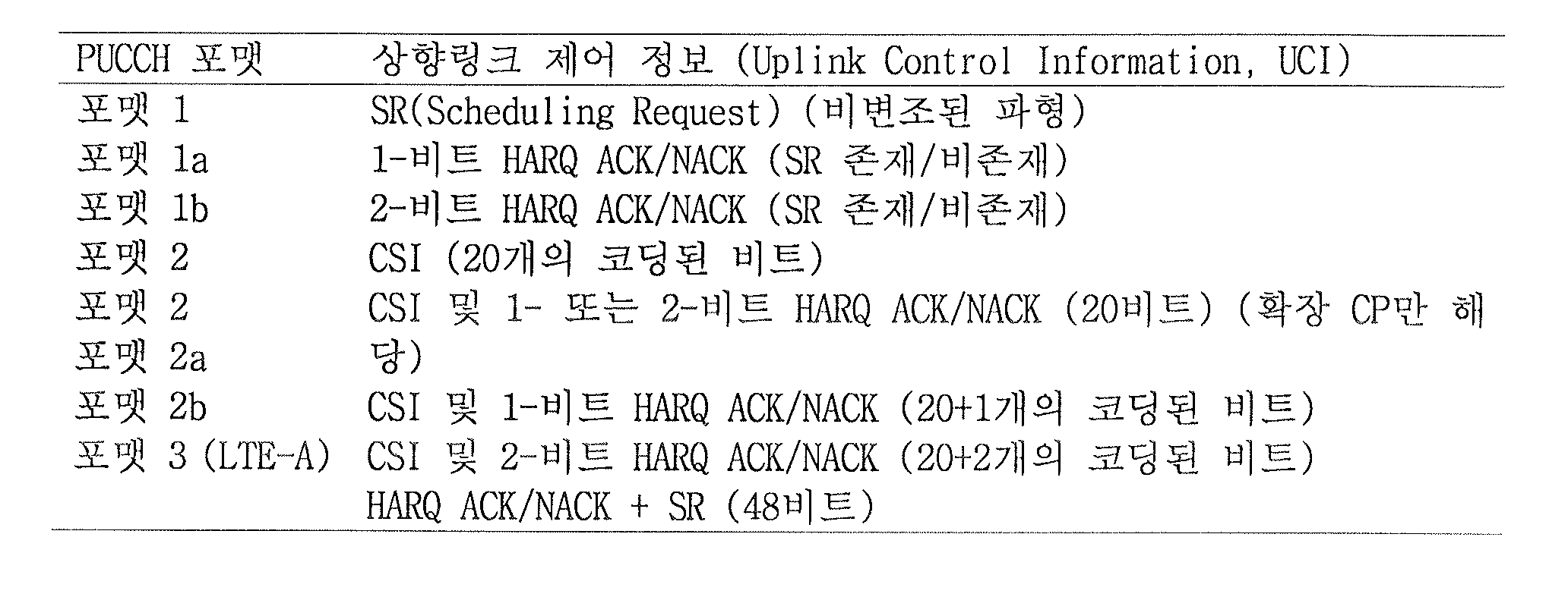
표 3은 LTE에서 PUCCH 포맷과 UCI의 맵핑 관계를 나타낸다.Table 3 shows mapping relationship between PUCCH format and UCI in LTE.
도 5는 PUCCH 포맷 1a/1b의 슬롯 레벨 구조를 나타낸다. PUCCH 포맷 1a/1b는 ACK/NACK 전송에 사용된다. 노멀 CP인 경우 SC-FDMA #2/#3/#4가 DM RS (Demodulation Reference Signal) 전송에 사용된다. 확장 CP인 경우 SC-FDMA #2/#3이 DM RS 전송에 사용된다. 따라서, 슬롯에서 4개의 SC-FDMA 심볼이 ACK/NACK 전송에 사용된다. 편의상, PUCCH 포맷 1a/1b를 PUCCH 포맷 1이라고 통칭한다.5 shows a slot level structure of the PUCCH format 1a / 1b. PUCCH format 1a / 1b is used for ACK / NACK transmission. In case of normal CP, SC-FDMA # 2 / # 3 / # 4 is used for DM RS (Demodulation Reference Signal) transmission. In case of an extended CP, SC-FDMA # 2 / # 3 is used for DM RS transmission. Thus, four SC-FDMA symbols in the slot are used for ACK / NACK transmission. For convenience, PUCCH format 1a / 1b is collectively referred to as PUCCH format 1.
도 5를 참조하면, 1비트[b(0)] 및 2비트[b(0)b(1)] ACK/NACK 정보는 각각 BPSK(Binary Phase Shift Keying) 및 QPSK(Quadrature Phase Shift Keying) 변조 방식에 따라 변조되며, 하나의 ACK/NACK 변조 심볼이 생성된다(d0). ACK/NACK 정보에서 각각의 비트[b(i),i=0,1]는 해당 DL 전송블록에 대한 HARQ 응답을 나타내며, 포지티브 ACK일 경우 해당 비트는 1로 주어지고 네거티브 ACK(NACK)일 경우 해당 비트는 0으로 주어진다. 표 4는 기존 LTE에서 PUCCH 포맷 1a 및 1b를 위해 정의된 변조 테이블을 나타낸다.Referring to FIG. 5, 1 bit [b (0)] and 2 bit [b (0) b (1)] ACK / NACK information are respectively Binary Phase Shift Keying (BPSK) and Quadrature Phase Shift Keying (QPSK) modulation schemes. Is modulated according to the present invention, and one ACK / NACK modulation symbol is generated (d0). Each bit [b (i), i = 0,1] in the ACK / NACK information indicates a HARQ response for the corresponding DL transport block.In the case of positive ACK, the corresponding bit is given as 1 and a negative ACK (NACK). The bit is given as zero. Table 4 shows a modulation table defined for PUCCH formats 1a and 1b in legacy LTE.
PUCCH 포맷 1a/1b는 주파수 도메인에서 사이클릭 쉬프트(αcs,x)를 수행하고, 시간 도메인에서 직교 확산 코드(예, Walsh-Hadamard 또는 DFT 코드)(w0,w1,w2,w3)를 이용하여 확산을 한다. 주파수 및 시간 도메인 모두에서 코드 다중화가 사용되므로 보다 많은 단말이 동일한 PUCCH RB 상에 다중화 될 수 있다.PUCCH formats 1a / 1b perform cyclic shifts (αcs, x) in the frequency domain and spread using orthogonal spreading codes (e.g. Walsh-Hadamard or DFT code) (w0, w1, w2, w3) in the time domain Do it. Since code multiplexing is used in both frequency and time domain, more terminals can be multiplexed on the same PUCCH RB.
도 6은 ACK/NACK을 위한 PUCCH 자원을 결정하는 예를 나타낸다. LTE(-A) 시스템에서 ACK/NACK을 위한 PUCCH 자원은 각 단말에게 미리 할당되어 있지 않고, 복수의 PUCCH 자원을 셀 내의 복수의 단말들이 매 시점마다 나눠서 사용한다. 구체적으로, 단말이 ACK/NACK을 전송하는데 사용하는 PUCCH 자원은 해당 하향링크 데이터에 대한 스케줄링 정보를 나르는 PDCCH 혹은 SPS 해제를 지시하는 PDCCH에 대응된다. 각 하향링크 서브프레임에서 단말에게 전송되는 PDCCH는 하나 이상의 CCE(Control Channel Element)로 구성된다. 단말은 해당 PDCCH를 구성하는 CCE들 중 특정 CCE (예, 첫 번째 CCE)에 대응되는 PUCCH 자원을 통해 ACK/NACK을 전송할 수 있다. 6 shows an example of determining a PUCCH resource for ACK / NACK. In the LTE (-A) system, the PUCCH resources for ACK / NACK are not allocated to each UE in advance, and a plurality of PUCCH resources are divided and used at every time point by a plurality of UEs in a cell. In detail, the PUCCH resource used by the UE to transmit ACK / NACK corresponds to a PDCCH carrying scheduling information for corresponding downlink data or a PDCCH indicating SPS release. The PDCCH transmitted to the UE in each downlink subframe includes one or more Control Channel Elements (CCEs). The UE may transmit ACK / NACK through a PUCCH resource corresponding to a specific CCE (eg, the first CCE) among the CCEs configuring the corresponding PDCCH.
도 6을 참조하면, 하향링크 콤포넌트 반송파(DownLink Component Carrier, DL CC)에서 각 사각형은 CCE를 나타내고, 상향링크 콤포넌트 반송파(UpLink Component Carrier, UL CC)에서 각 사각형은 PUCCH 자원을 나타낸다. 각각의 PUCCH 인덱스는 ACK/NACK을 위한 PUCCH 자원에 대응된다. 도 6에서와 같이 4~6 번 CCE로 구성된 PDCCH를 통해 PDSCH에 대한 정보가 전달된다고 가정할 경우, 단말은 PDCCH를 구성하는 첫 번째 CCE인 4번 CCE에 대응되는 4번 PUCCH를 통해 ACK/NACK을 전송한다.Referring to FIG. 6, each square represents a CCE in a downlink component carrier (DL CC), and each square represents a PUCCH resource in an uplink component carrier (UL CC). Each PUCCH index corresponds to a PUCCH resource for ACK / NACK. If it is assumed that the information on the PDSCH is transmitted through the PDCCH configured to 4 ~ 6 CCE as shown in Figure 6, the UE ACK / NACK through the 4 PUCCH corresponding to the 4 CCE, the first CCE constituting the PDCCH Send it.
구체적으로, LTE(-A) 시스템에서 PUCCH 자원 인덱스는 다음과 같이 정해진다.Specifically, the PUCCH resource index in the LTE (-A) system is determined as follows.
[수학식 1][Equation 1]
n(1)
PUCCH = nCCE + N(1)
PUCCH
n (1) PUCCH = n CCE + N (1) PUCCH
여기에서, n(1)
PUCCH는 ACK/NACK/DTX을 전송하기 위한 PUCCH 포맷 1a/1b의 자원 인덱스를 나타내고, N(1)
PUCCH는 상위계층으로부터 전달받는 시그널링 값을 나타내며, nCCE는 PDCCH 전송에 사용된 CCE 인덱스 중에서 가장 작은 값을 나타낸다. n(1)
PUCCH로부터 PUCCH 포맷 1a/1b를 위한 사이클릭 쉬프트, 직교 확산 코드 및 PRB(Physical Resource Block)가 얻어진다.Here, n (1) PUCCH represents a resource index of PUCCH format 1a / 1b for transmitting ACK / NACK / DTX, N (1) PUCCH represents a signaling value received from a higher layer, n CCE is a PDCCH transmission Represents the smallest value among the CCE indexes used in. n (1) From the PUCCH , a cyclic shift, an orthogonal spreading code, and a PRB (Physical Resource Block) for PUCCH formats 1a / 1b are obtained.
한편, LTE 단말은 PUCCH와 PUSCH를 동시에 전송할 수 없으므로 PUSCH가 전송되는 서브프레임에서 UCI(예, CQI/PMI, HARQ-ACK, RI 등) 전송이 필요한 경우, UCI를 PUSCH 영역에 다중화 한다(PUSCH 피기백). LTE-A에서도 단말이 PUCCH와 PUSCH를 동시에 전송하지 못하도록 구성될 수 있다. 이 경우, PUSCH가 전송되는 서브프레임에서 UCI(예, CQI/PMI, HARQ-ACK, RI 등) 전송이 필요한 경우, 단말은 UCI를 PUSCH 영역에 다중화 할 수 있다(PUSCH 피기백).Meanwhile, since the LTE terminal cannot transmit the PUCCH and the PUSCH at the same time, when UCI (eg, CQI / PMI, HARQ-ACK, RI, etc.) transmission is required in the subframe in which the PUSCH is transmitted, the UCI is multiplexed in the PUSCH region (PUSCH Piggy) back). In LTE-A, the UE may be configured to not simultaneously transmit the PUCCH and the PUSCH. In this case, when UCI (eg, CQI / PMI, HARQ-ACK, RI, etc.) transmission is required in a subframe in which the PUSCH is transmitted, the UE may multiplex the UCI in the PUSCH region (PUSCH piggyback).
도 7은 단일 셀 상황에서 TDD UL ACK/NACK 전송 과정을 나타낸다. 7 shows a TDD UL ACK / NACK transmission process in a single cell situation.
도 7을 참조하면, 단말은 M개의 DL 서브프레임(Subframe, SF) 상에서 하나 이상의 DL 전송(예, PDSCH 신호)를 수신할 수 있다(S502_0~S502_M-1). 각각의 PDSCH 신호는 전송 모드에 따라 하나 또는 복수(예, 2개)의 전송블록(TB)(혹은 코드워드(CW))을 전송하는데 사용된다. 또한, 도시하지는 않았지만, 단계 S502_0~S502_M-1에서 ACK/NACK 응답을 요하는 PDCCH 신호, 예를 들어 SPS 해제를 지시하는 PDCCH 신호(간단히, SPS 해제 PDCCH 신호)도 수신될 수 있다. M개의 DL 서브프레임에 PDSCH 신호 및/또는 SPS 해제 PDCCH 신호가 존재하면, 단말은 ACK/NACK을 전송하기 위한 과정(예, ACK/NACK (페이로드) 생성, ACK/NACK 자원 할당 등)을 거쳐, M개의 DL 서브프레임에 대응하는 하나의 UL 서브프레임을 통해 ACK/NACK을 전송한다(S504). ACK/NACK은 단계 S502_0~S502_M-1의 PDSCH 신호 및/또는 SPS 해제 PDCCH 신호에 대한 수신 응답 정보를 포함한다. ACK/NACK은 기본적으로 PUCCH를 통해 전송되지만(예, 도 5~6 참조), ACK/NACK 전송 시점에 PUSCH 전송이 있는 경우 ACK/NACK은 PUSCH를 통해 전송될 수 있다. ACK/NACK 전송을 위해 표 3의 다양한 PUCCH 포맷이 사용될 수 있다. 또한, 전송되는 ACK/NACK 비트 수를 줄이기 위해 ACK/NACK 번들링(bundling), ACK/NACK 채널 선택(channel selection)과 같은 다양한 방법이 사용될 수 있다.Referring to FIG. 7, the UE may receive one or more DL transmissions (eg, PDSCH signals) on M DL subframes (SFs) (S502_0 to S502_M-1). Each PDSCH signal is used to transmit one or more (eg, two) TBs (or codewords) according to a transmission mode. Although not shown, a PDCCH signal requiring an ACK / NACK response, for example, a PDCCH signal (simply, an SPS release PDCCH signal) indicating an SPS release may be received in steps S502_0 to S502_M-1. If there are PDSCH signals and / or SPS release PDCCH signals in the M DL subframes, the UE goes through a process for transmitting ACK / NACK (eg, ACK / NACK (payload) generation, ACK / NACK resource allocation, etc.). In operation S504, ACK / NACK is transmitted through one UL subframe corresponding to the M DL subframes. The ACK / NACK includes reception response information for the PDSCH signal and / or the SPS release PDCCH signal of steps S502_0 to S502_M-1. The ACK / NACK is basically transmitted through the PUCCH (eg, see FIGS. 5 to 6), but when there is a PUSCH transmission at the time of the ACK / NACK transmission, the ACK / NACK may be transmitted through the PUSCH. Various PUCCH formats shown in Table 3 may be used for ACK / NACK transmission. In addition, various methods such as ACK / NACK bundling and ACK / NACK channel selection may be used to reduce the number of transmitted ACK / NACK bits.
상술한 바와 같이, TDD에서는 M개의 DL 서브프레임에서 수신한 데이터에 대한 ACK/NACK이 하나의 UL 서브프레임을 통해 전송되며(즉, M DL SF(s):1 UL SF), 이들간의 관계는 DASI(Downlink Association Set Index)에 의해 주어진다.As described above, in TDD, ACK / NACK for data received in M DL subframes is transmitted through one UL subframe (that is, M DL SF (s): 1 UL SF), and the relationship between them is It is given by the Downlink Association Set Index (DASI).
표 5는 LTE(-A)에 정의된 DASI(K:{k0,k1,…kM-1})를 나타낸다. 표 5는 ACK/NACK을 전송하는 UL 서브프레임 입장에서 자신과 연관된 DL 서브프레임과의 간격을 나타낸다. 구체적으로, 서브프레임 n-k (k∈K)에 PDSCH 전송 및/또는 SPS 해제 PDCCH가 있는 경우, 단말은 서브프레임 n에서 대응하는 ACK/NACK을 전송한다.Table 5 shows DASI (K: {k 0 , k 1 ,... K M-1 }) defined in LTE (-A). Table 5 shows the interval with the DL subframe associated with itself in the UL subframe for transmitting the ACK / NACK. Specifically, if there is PDSCH transmission and / or SPS release PDCCH in subframe nk (k∈K), the UE transmits a corresponding ACK / NACK in subframe n.
TDD 방식으로 동작 시, 단말은 M개의 DL SF를 통해 수신한 하나 이상의 DL 전송(예, PDSCH)에 대한 ACK/NACK 신호를 하나의 UL SF를 통해 전송해야 한다. 복수의 DL SF에 대한 ACK/NACK을 하나의 UL SF를 통해 전송하는 방식은 다음과 같다.When operating in the TDD scheme, the UE should transmit ACK / NACK signals for one or more DL transmissions (eg, PDSCHs) received through M DL SFs through one UL SF. A method of transmitting ACK / NACK for a plurality of DL SFs through one UL SF is as follows.
1) ACK/NACK 번들링(ACK/NACK bundling): 복수의 데이터 유닛(예, PDSCH, SPS 해제 PDCCH 등)에 대한 ACK/NACK 비트가 논리 연산(예, 논리-AND 연산)에 의해 결합된다. 예를 들어, 모든 데이터 유닛이 성공적으로 복호되면, 수신단(예, 단말)은 ACK 신호를 전송한다. 반면, 데이터 유닛 중 하나라도 복호(또는 검출)가 실패하면, 수신단은 NACK 신호를 전송하거나 아무것도 전송하지 않는다.1) ACK / NACK bundling: ACK / NACK bits for a plurality of data units (eg PDSCH, SPS release PDCCH, etc.) are combined by a logical operation (eg, a logical-AND operation). For example, if all data units are successfully decoded, the receiving end (eg, terminal) transmits an ACK signal. On the other hand, when decoding (or detecting) one of the data units fails, the receiving end transmits a NACK signal or nothing.
2) 채널 선택(channel selection): 복수의 데이터 유닛(예, PDSCH, SPS 해제 PDCCH 등)을 수신하는 단말은 ACK/NACK 전송을 위해 복수의 PUCCH 자원들을 점유한다. 복수의 데이터 유닛에 대한 ACK/NACK 응답은 실제 ACK/NACK 전송에 사용된 PUCCH 자원과 전송된 ACK/NACK 내용(예, 비트 값, QPSK 심볼 값)의 조합에 의해 식별된다. 채널 선택 방식은 ACK/NACK 선택 방식, PUCCH 선택 방식으로도 지칭된다.2) channel selection: A terminal receiving a plurality of data units (eg, PDSCH, SPS release PDCCH, etc.) occupies a plurality of PUCCH resources for ACK / NACK transmission. The ACK / NACK response for the plurality of data units is identified by the combination of the PUCCH resource used for the actual ACK / NACK transmission and the transmitted ACK / NACK content (eg, bit value, QPSK symbol value). The channel selection method is also referred to as an ACK / NACK selection method and a PUCCH selection method.
채널 선택 방식에 대해 보다 구체적으로 설명한다. 채널 선택 방식에서 단말은 복수의 하향링크 데이터를 수신한 경우에 다중화된 ACK/NACK 신호를 전송하기 위해 복수의 상향링크 물리 채널 자원(예, PUCCH 자원)을 점유한다. 일 예로, 단말은 복수의 PDSCH를 수신한 경우에 각 PDSCH를 지시하는 PDCCH의 특정 CCE를 이용해 동일한 수의 PUCCH 자원을 점유할 수 있다. 이 경우, 점유한 복수의 PUCCH 자원 중 어느 PUCCH 자원을 선택하는가와 선택한 PUCCH 자원에 적용되는 변조/부호화된 내용의 조합을 이용해 다중화된 ACK/NACK 신호를 전송할 수 있다.The channel selection method will be described in more detail. In the channel selection scheme, the terminal occupies a plurality of uplink physical channel resources (eg, PUCCH resources) to transmit multiplexed ACK / NACK signals when a plurality of downlink data is received. For example, when a plurality of PDSCHs are received, the UE may occupy the same number of PUCCH resources by using a specific CCE of a PDCCH indicating each PDSCH. In this case, the multiplexed ACK / NACK signal may be transmitted using a combination of a PUCCH resource selected from a plurality of occupied PUCCH resources and a modulation / coded content applied to the selected PUCCH resource.
표 6은 LTE 시스템에 정의된 채널 선택용 매핑 테이블을 예시한다.Table 6 illustrates a mapping table for channel selection defined in the LTE system.
표 6에서, HARQ-ACK(i)는 i-번째 데이터 유닛(0≤i≤3)의 HARQ ACK/NACK/DTX 응답을 나타낸다. HARQ ACK/NACK/DTX 응답은 ACK, NACK, DTX, NACK/DTX를 포함한다. NACK/DTX는 NACK 또는 DTX를 나타낸다. ACK 및 NACK은 PDSCH를 통해 전송된 전송블록(코드블록과 등가이다)의 디코딩 성공 및 실패를 나타낸다. DTX(Discontinuous Transmission)는 PDCCH 검출 실패를 나타낸다. 각각의 데이터 유닛과 관련하여 최대 4개의 PUCCH 자원(즉, n(1)
PUCCH,0 ~ n(1)
PUCCH,3)이 점유될 수 있다. 다중화된 ACK/NACK은 점유된 PUCCH 자원으로부터 선택된 하나의 PUCCH 자원을 통해 전송된다. 표 6에 기재된 n(1)
PUCCH,i는 실제로 ACK/NACK을 전송하는데 사용되는 PUCCH 자원을 나타낸다. b(0)b(1)은 선택된 PUCCH 자원을 통해 전송되는 두 비트를 나타내며 QPSK 방식으로 변조된다. 일 예로, 단말이 4개의 데이터 유닛을 성공적으로 복호한 경우, 단말은 n(1)
PUCCH,1와 연결된 PUCCH 자원을 통해 (1,1)을 기지국으로 전송한다. PUCCH 자원과 QPSK 심볼의 조합이 가능한 ACK/NACK 가정을 모두 나타내기에 부족하므로 일부의 경우를 제외하고는 NACK과 DTX는 커플링 된다(NACK/DTX, N/D).In Table 6, HARQ-ACK (i) represents the HARQ ACK / NACK / DTX response of the i-th data unit (0 ≦ i ≦ 3). HARQ ACK / NACK / DTX response includes ACK, NACK, DTX, NACK / DTX. NACK / DTX stands for NACK or DTX. ACK and NACK indicate the success and failure of decoding of a transport block (equivalent to a code block) transmitted on a PDSCH. Discontinuous Transmission (DTX) indicates PDCCH detection failure. Up to four PUCCH resources (ie, n (1) PUCCH, 0 to n (1) PUCCH, 3 ) may be occupied for each data unit. The multiplexed ACK / NACK is transmitted on one PUCCH resource selected from occupied PUCCH resources. N (1) PUCCH, i described in Table 6 represents the PUCCH resources used to actually transmit ACK / NACK. b (0) b (1) represents two bits transmitted through the selected PUCCH resource and is modulated by the QPSK scheme. For example, when the terminal successfully decodes four data units, the terminal transmits (1,1) to the base station through a PUCCH resource connected with n (1) PUCCH, 1 . Since the combination of PUCCH resources and QPSK symbols is insufficient to represent all possible ACK / NACK hypotheses, except for some cases, NACK and DTX are coupled (NACK / DTX, N / D).
도 8은 캐리어 병합(Carrier Aggregation, CA) 통신 시스템을 예시한다. LTE-A 시스템은 보다 넓은 주파수 대역을 사용하기 위해 복수의 UL/DL 주파수 블록을 모다 더 큰 UL/DL 대역폭을 사용하는 캐리어 병합(carrier aggregation 또는 bandwidth aggregation) 기술을 사용한다. 각 주파수 블록은 콤포넌트 캐리어(Component Carrier, CC)를 이용해 전송된다. 콤포넌트 캐리어는 해당 주파수 블록을 위한 캐리어 주파수 (또는 중심 캐리어, 중심 주파수)로 이해될 수 있다.8 illustrates a Carrier Aggregation (CA) communication system. The LTE-A system collects a plurality of UL / DL frequency blocks to use a wider frequency band and uses a carrier aggregation or bandwidth aggregation technique that uses a larger UL / DL bandwidth. Each frequency block is transmitted using a component carrier (CC). The component carrier may be understood as the carrier frequency (or center carrier, center frequency) for the corresponding frequency block.
도 8을 참조하면, 복수의 UL/DL 콤포넌트 캐리어(Component Carrier, CC)들을 모아 더 넓은 UL/DL 대역폭을 지원할 수 있다. CC들은 주파수 영역에서 서로 인접하거나 비-인접할 수 있다. 각 CC의 대역폭은 독립적으로 정해질 수 있다. UL CC의 개수와 DL CC의 개수가 다른 비대칭 캐리어 병합도 가능하다. 예를 들어, DL CC 2개 UL CC 1개인 경우에는 2:1로 대응되도록 구성이 가능하다. DL CC/UL CC 링크는 시스템에 고정되어 있거나 반-정적으로 구성될 수 있다. 또한, 시스템 전체 대역이 N개의 CC로 구성되더라도 특정 단말이 모니터링/수신할 수 있는 주파수 대역은 L(<N)개의 CC로 한정될 수 있다. 캐리어 병합에 대한 다양한 파라미터는 셀 특정(cell-specific), 단말 그룹 특정(UE group-specific) 또는 단말 특정(UE-specific) 방식으로 설정될 수 있다. 한편, 제어 정보는 특정 CC를 통해서만 송수신 되도록 설정될 수 있다. 이러한 특정 CC를 프라이머리 CC(Primary CC, PCC)(또는 앵커 CC)로 지칭하고, 나머지 CC를 세컨더리 CC(Secondary CC, SCC)로 지칭할 수 있다.Referring to FIG. 8, a plurality of UL / DL component carriers (CCs) may be collected to support a wider UL / DL bandwidth. CCs may be adjacent or non-adjacent to each other in the frequency domain. The bandwidth of each CC can be determined independently. It is also possible to merge asymmetric carriers in which the number of UL CCs and the number of DL CCs are different. For example, in case of two DL CCs and one UL CC, the configuration may be configured to correspond to 2: 1. The DL CC / UL CC link may be fixed in the system or configured semi-statically. In addition, even if the entire system band is composed of N CCs, a frequency band that can be monitored / received by a specific terminal may be limited to L (<N) CCs. Various parameters for carrier aggregation may be set in a cell-specific, UE group-specific or UE-specific manner. Meanwhile, the control information may be set to be transmitted and received only through a specific CC. This particular CC may be referred to as a primary CC (or PCC) (or anchor CC), and the remaining CC may be referred to as a secondary CC (SCC).
LTE-A는 무선 자원을 관리하기 위해 셀(cell)의 개념을 사용한다[36.300 V10.2.0 (2010-12) 5.5. Carrier Aggregation; 7.5. Carrier Aggregation 참조]. 셀은 하향링크 자원과 상향링크 자원의 조합으로 정의되며, 상향링크 자원은 필수 요소는 아니다. 따라서, 셀은 하향링크 자원 단독, 또는 하향링크 자원과 상향링크 자원으로 구성될 수 있다. 캐리어 병합이 지원되는 경우, 하향링크 자원의 캐리어 주파수(또는, DL CC)와 상향링크 자원의 캐리어 주파수(또는, UL CC) 사이의 링키지(linkage)는 시스템 정보에 의해 지시될 수 있다. 프라이머리 주파수(또는 PCC) 상에서 동작하는 셀을 프라이머리 셀(Primary Cell, PCell)로 지칭하고, 세컨더리 주파수(또는 SCC) 상에서 동작하는 셀을 세컨더리 셀(Secondary Cell, SCell)로 지칭할 수 있다. PCell은 단말이 초기 연결 설정(initial connection establishment) 과정을 수행하거나 연결 재-설정 과정을 수행하는데 사용된다. PCell은 핸드오버 과정에서 지시된 셀을 지칭할 수도 있다. SCell은 RRC 연결이 설정이 이루어진 이후에 구성 가능하고 추가적인 무선 자원을 제공하는데 사용될 수 있다. PCell과 SCell은 서빙 셀로 통칭될 수 있다. 따라서, RRC_CONNECTED 상태에 있지만 캐리어 병합이 설정되지 않았거나 캐리어 병합을 지원하지 않는 단말의 경우, PCell로만 구성된 서빙 셀이 단 하나 존재한다. 반면, RRC_CONNECTED 상태에 있고 캐리어 병합이 설정된 단말의 경우, 하나 이상의 서빙 셀이 존재하고 전체 서빙 셀에는 PCell과 전체 SCell이 포함된다. 캐리어 병합을 위해, 네트워크는 초기 보안 활성화(initial security activation) 과정이 개시된 이후, 연결 설정 과정에서 초기에 구성되는 PCell에 부가하여 하나 이상의 SCell을 캐리어 병합을 지원하는 단말을 위해 구성할 수 있다.LTE-A uses the concept of a cell to manage radio resources [36.300 V10.2.0 (2010-12) 5.5. Carrier Aggregation; 7.5. See Carrier Aggregation]. A cell is defined as a combination of downlink resources and uplink resources, and uplink resources are not required. Accordingly, the cell may be configured with only downlink resources or with downlink resources and uplink resources. If carrier aggregation is supported, the linkage between the carrier frequency (or DL CC) of the downlink resource and the carrier frequency (or UL CC) of the uplink resource may be indicated by system information. A cell operating on the primary frequency (or PCC) may be referred to as a primary cell (PCell), and a cell operating on the secondary frequency (or SCC) may be referred to as a secondary cell (SCell). The PCell is used by the terminal to perform an initial connection establishment process or to perform a connection re-establishment process. PCell may refer to a cell indicated in the handover process. The SCell is configurable after the RRC connection is established and can be used to provide additional radio resources. PCell and SCell may be collectively referred to as a serving cell. Therefore, in the case of the UE that is in the RRC_CONNECTED state, but carrier aggregation is not configured or does not support carrier aggregation, there is only one serving cell configured only with the PCell. On the other hand, in a terminal in the RRC_CONNECTED state and carrier aggregation is configured, one or more serving cells exist, and the entire serving cell includes the PCell and the entire SCell. For carrier aggregation, after the initial security activation process is initiated, the network may configure one or more SCells for the UE supporting carrier aggregation in addition to the PCell initially configured in the connection establishment process.
크로스-캐리어 스케줄링 (또는 크로스-CC 스케줄링)이 적용될 경우, 하향링크 할당을 위한 PDCCH는 DL CC#0으로 전송되고, 해당 PDSCH는 DL CC#2로 전송될 수 있다. 크로스-CC 스케줄링을 위해, 캐리어 지시 필드(Carrier Indicator Field, CIF)의 도입이 고려될 수 있다. PDCCH 내에서 CIF의 존재 여부는 상위 계층 시그널링(예, RRC 시그널링)에 의해 반-정적 및 단말-특정(또는 단말 그룹-특정) 방식으로 설정될 수 있다. PDCCH 전송의 베이스 라인을 요약하면 다음과 같다.When cross-carrier scheduling (or cross-CC scheduling) is applied, the PDCCH for downlink allocation may be transmitted on DL CC # 0, and the corresponding PDSCH may be transmitted on DL CC # 2. For cross-CC scheduling, the introduction of a Carrier Indicator Field (CIF) may be considered. The presence or absence of the CIF in the PDCCH may be set in a semi-static and terminal-specific (or terminal group-specific) manner by higher layer signaling (eg, RRC signaling). The baseline of PDCCH transmission is summarized as follows.
- CIF 디스에이블드(disabled): DL CC 상의 PDCCH는 동일한 DL CC 상의 PDSCH 자원을 할당하거나 하나의 링크된 UL CC 상의 PUSCH 자원을 할당CIF disabled: PDCCH on DL CC allocates PDSCH resources on the same DL CC or PUSCH resources on one linked UL CC
- CIF 이네이블드(enabled): DL CC 상의 PDCCH는 CIF를 이용하여 복수의 병합된 DL/UL CC 중에서 특정 DL/UL CC 상의 PDSCH 또는 PUSCH 자원을 할당 가능CIF enabled: PDCCH on DL CC can allocate PDSCH or PUSCH resource on a specific DL / UL CC among a plurality of merged DL / UL CCs using CIF
CIF가 존재할 경우, 기지국은 단말 측의 BD 복잡도를 낮추기 위해 PDCCH 모니터링 DL CC 세트를 할당할 수 있다. PDCCH 모니터링 DL CC 세트는 병합된 전체 DL CC의 일부로서 하나 이상의 DL CC를 포함하고 단말은 해당 DL CC 상에서만 PDCCH의 검출/디코딩을 수행한다. 즉, 기지국이 단말에게 PDSCH/PUSCH를 스케줄링 할 경우, PDCCH는 PDCCH 모니터링 DL CC 세트를 통해서만 전송된다. PDCCH 모니터링 DL CC 세트는 단말-특정(UE-specific), 단말-그룹-특정 또는 셀-특정(cell-specific) 방식으로 설정될 수 있다. 용어 “PDCCH 모니터링 DL CC”는 모니터링 캐리어, 모니터링 셀 등과 같은 등가의 용어로 대체될 수 있다. 또한, 단말을 위해 병합된 CC는 서빙 CC, 서빙 캐리어, 서빙 셀 등과 같은 등가의 용어로 대체될 수 있다.If the CIF exists, the base station may allocate the PDCCH monitoring DL CC set to reduce the BD complexity of the terminal side. The PDCCH monitoring DL CC set includes one or more DL CCs as part of the merged total DL CCs, and the UE performs detection / decoding of the PDCCH only on the corresponding DL CCs. That is, when the base station schedules PDSCH / PUSCH to the UE, the PDCCH is transmitted only through the PDCCH monitoring DL CC set. The PDCCH monitoring DL CC set may be configured in a UE-specific, UE-group-specific or cell-specific manner. The term “PDCCH monitoring DL CC” may be replaced with equivalent terms such as a monitoring carrier, a monitoring cell, and the like. In addition, the CC merged for the terminal may be replaced with equivalent terms such as a serving CC, a serving carrier, a serving cell, and the like.
도 9는 복수의 캐리어가 병합된 경우의 스케줄링을 예시한다. 도면은 3개의 DL CC가 병합되고, DL CC A가 PDCCH 모니터링 DL CC로 설정된 경우를 예시한다. DL CC A~C는 서빙 CC, 서빙 캐리어, 서빙 셀 등으로 지칭될 수 있다. CIF가 디스에이블 된 경우, 각각의 DL CC는 LTE PDCCH 규칙에 따라 CIF 없이 자신의 PDSCH를 스케줄링 하는 PDCCH만을 전송할 수 있다. 반면, CIF가 이네이블 된 경우, DL CC A(모니터링 DL CC)는 CIF를 이용하여 DL CC A의 PDSCH를 스케줄링 하는 PDCCH뿐만 아니라 다른 CC의 PDSCH를 스케줄링 하는 PDCCH도 전송할 수 있다. 이 경우, PDCCH 모니터링 DL CC로 설정되지 않은 DL CC B/C에서는 PDCCH가 전송되지 않는다.9 illustrates scheduling when a plurality of carriers are merged. The figure illustrates a case in which three DL CCs are merged and DL CC A is set to a PDCCH monitoring DL CC. DL CC A to C may be referred to as a serving CC, a serving carrier, a serving cell, and the like. When the CIF is disabled, each DL CC may transmit only the PDCCH scheduling its PDSCH without the CIF according to the LTE PDCCH rule. On the other hand, when the CIF is enabled, the DL CC A (monitoring DL CC) may transmit not only the PDCCH scheduling the PDSCH of the DL CC A but also the PDCCH scheduling the PDSCH of another CC using the CIF. In this case, PDCCH is not transmitted in DL CC B / C that is not configured as PDCCH monitoring DL CC.
이하, TDD CA에서 HARQ-ACK 전송을 위해, PUCCH 포맷 1b를 이용한 채널 선택 방식이 설정된 경우에 대해 설명한다. 기존의 LTE-A는 동일한 TDD UL-DL Cfg를 갖는 2개의 서빙 셀(즉, PCell과 SCell)(혹은 PCC와 SCC)이 병합된 경우를 가정한다.Hereinafter, a case in which a channel selection scheme using PUCCH format 1b is set for HARQ-ACK transmission in a TDD CA will be described. The existing LTE-A assumes a case where two serving cells (ie, PCell and SCell) (or PCC and SCC) having the same TDD UL-DL Cfg are merged.
먼저, HARQ-ACK 전송을 위한 UL 서브프레임 n에서 M≤2인 경우에 PUCCH 포맷 1b를 이용한 채널 선택 방식에 대해 설명한다. 여기서, M은 표 5를 참조하여 설명한 K 집합에 원소 개수(즉, UL SF에 대응하는 DL SF의 개수)에 해당한다. UL 서브프레임 n에서 M≤2인 경우, 단말은 A개의 PUCCH 자원들(n(1)
PUCCH,i)로부터 선택된 PUCCH 자원 상에서 b(0)b(1)을 전송할 수 있다(0≤i≤A-1 및 A⊂{2,3,4}). 구체적으로, 단말은 UL 서브프레임 n에서 PUCCH 포맷 1b를 이용하여 표 7~9에 따라 A/N 신호를 전송한다. UL 서브프레임 n에서 M=1인 경우, HARQ-ACK(j)는 서빙 셀 c와 관련된, 전송 블록 또는 SPS 해제 PDCCH에 대한 A/N 응답을 나타낸다. 여기서, M=1인 경우, 전송 블록, HARQ-ACK(j) 및 A개의 PUCCH 자원은 표 10에 의해 주어질 수 있다. UL 서브프레임 n에서 M=2인 경우, HARQ-ACK(j)는 각 서빙 셀에서 집합 K에 의해 주어진 DL 서브프레임(들) 내에서, 전송 블록 또는 SPS 해제 PDCCH에 대한 A/N 응답을 나타낸다. 여기서, M=2인 경우, HARQ-ACK(j)를 위한 각 서빙 셀 상의 서브프레임들 및 A개의 PUCCH 자원들은 표 11에 의해 주어질 수 있다.First, a channel selection method using PUCCH format 1b in case of M≤2 in UL subframe n for HARQ-ACK transmission will be described. Here, M corresponds to the number of elements (that is, the number of DL SFs corresponding to UL SF) in the K set described with reference to Table 5. If M ≦ 2 in UL subframe n, the UE may transmit b (0) b (1) on a PUCCH resource selected from A PUCCH resources n (1) PUCCH, i (0 ≦ i ≦ A -1 and A '{2,3,4}). Specifically, the UE transmits the A / N signal according to Tables 7 to 9 using the PUCCH format 1b in UL subframe n. If M = 1 in UL subframe n, HARQ-ACK (j) indicates an A / N response for the transport block or SPS release PDCCH, associated with serving cell c. Here, when M = 1, a transport block, HARQ-ACK (j) and A PUCCH resources may be given by Table 10. If M = 2 in UL subframe n, HARQ-ACK (j) indicates the A / N response for the transport block or SPS release PDCCH, within the DL subframe (s) given by set K in each serving cell. . Here, when M = 2, subframes and A PUCCH resources on each serving cell for HARQ-ACK (j) may be given by Table 11.
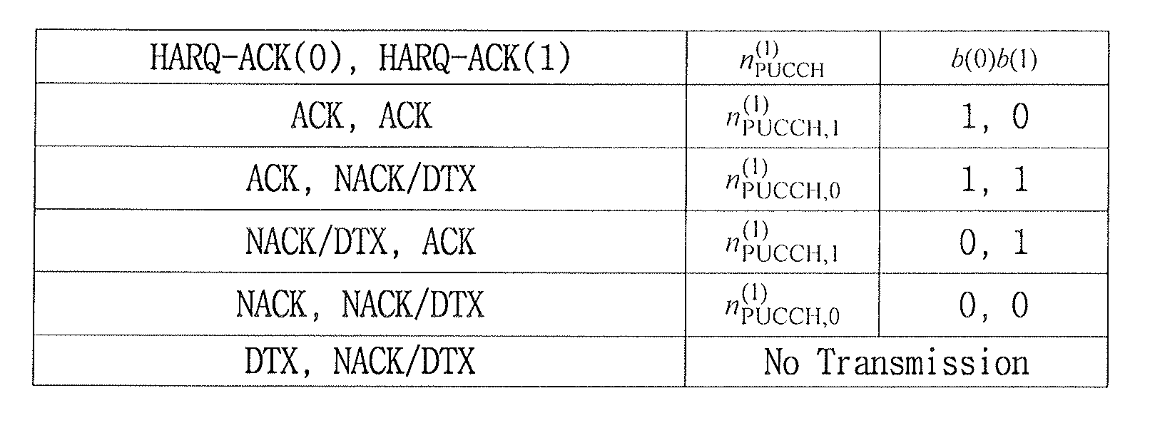
표 7은 동일한 UL-DL Cfg를 갖는 두 개의 CC가 병합되고, M=1 및 A=2인 경우에 LTE-A 시스템에 정의된 채널 선택용 매핑 테이블을 예시한다.Table 7 illustrates a mapping table for channel selection defined in the LTE-A system when two CCs having the same UL-DL Cfg are merged and M = 1 and A = 2.
여기서, n(1)
PUCCH,0는 PCC(혹은 PCell)를 스케줄링 하는 PDCCH(즉, PCC-PDCCH)에 링크된 묵시적 PUCCH 자원, n(1)
PUCCH,1에는 크로스 CC 스케줄링 여부에 따라 SCC를 스케줄링 하는 PDCCH(즉, SCC-PDCCH)에 링크된 묵시적 PUCCH 자원 혹은 RRC로 예약되는 명시적 PUCCH 자원이 각각 할당될 수 있다. 예를 들어, 크로스-CC 스케줄링 상황에서 n(1)
PUCCH,0에는 PCC-PDCCH에 링크된 묵시적 PUCCH 자원, n(1)
PUCCH,1에는 SCC-PDCCH에 링크된 묵시적 PUCCH 자원이 할당될 수 있다.Where n (1) PUCCH, 0 is an implicit PUCCH resource linked to a PDCCH (ie, PCC-PDCCH) scheduling a PCC (or PCell), and n (1) PUCCH, 1 is scheduling an SCC according to cross CC scheduling An implicit PUCCH resource linked to a PDCCH (ie, SCC-PDCCH) or an explicit PUCCH resource reserved for RRC may be allocated, respectively. For example, in a cross-CC scheduling situation, n (1) PUCCH, 0 may be assigned an implicit PUCCH resource linked to the PCC-PDCCH, and n (1) PUCCH, 1 may be assigned an implicit PUCCH resource linked to the SCC-PDCCH. .
표 8은 동일한 UL-DL Cfg를 갖는 두 개의 CC가 병합되고, M=1 및 A=3인 경우에 LTE-A 시스템에 정의된 채널 선택용 매핑 테이블을 예시한다.Table 8 illustrates a mapping table for channel selection defined in the LTE-A system when two CCs having the same UL-DL Cfg are merged and M = 1 and A = 3.
여기서, PCC가 MIMO CC이고 SCC가 논-MIMO CC인 경우 n(1)
PUCCH,0와 n(1)
PUCCH,1에는 PCC-PDCCH에 링크된 묵시적 PUCCH 자원, n(1)
PUCCH,2에는 크로스 CC 스케줄링 여부에 따라 SCC-PDCCH에 링크된 묵시적 PUCCH 자원 혹은 RRC로 예약되는 명시적 PUCCH 자원이 할당될 수 있다. 또한, PCC가 논-MIMO CC이고 SCC가 MIMO CC인 경우 n(1)
PUCCH,0에는 PCC-PDCCH에 링크된 묵시적 PUCCH 자원, n(1)
PUCCH,1과 n(1)
PUCCH,2에는 크로스 CC 스케줄링 여부에 따라 SCC-PDCCH에 링크된 묵시적 PUCCH 자원 혹은 RRC로 예약되는 명시적 PUCCH 자원이 할당될 수 있다.Here, when PCC is a MIMO CC and SCC is a non-MIMO CC, n (1) PUCCH, 0 and n (1) PUCCH, 1 are implicit PUCCH resources linked to PCC-PDCCH, and n (1) PUCCH, 2 are cross Depending on whether CC scheduling is performed, an implicit PUCCH resource linked to the SCC-PDCCH or an explicit PUCCH resource reserved by RRC may be allocated. In addition, when PCC is a non-MIMO CC and SCC is a MIMO CC, n (1) PUCCH, 0 is an implicit PUCCH resource linked to the PCC-PDCCH, n (1) PUCCH, 1 and n (1) PUCCH, 2 are cross Depending on whether CC scheduling is performed, an implicit PUCCH resource linked to the SCC-PDCCH or an explicit PUCCH resource reserved by RRC may be allocated.
표 9는 동일한 UL-DL Cfg를 갖는 두 개의 CC가 병합되고, M≤2 및 A=4인 경우에 LTE-A 시스템에 정의된 채널 선택용 매핑 테이블을 예시한다.Table 9 illustrates a mapping table for channel selection defined in the LTE-A system when two CCs having the same UL-DL Cfg are merged and M≤2 and A = 4.
여기서, 크로스-CC 스케줄링 여부에 관계없이 PCC(혹은 PCell)를 스케줄링 하는 PDCCH(즉, PCC-PDCCH)에 링크된 묵시적 PUCCH 자원, n(1)
PUCCH,2 및/또는 n(1)
PUCCH,3에는 크로스-CC 스케줄링 여부에 따라 SCC를 스케줄링 하는 PDCCH(즉, SCC-PDCCH)에 링크된 묵시적 PUCCH 자원 혹은 RRC로 예약되는 명시적 PUCCH 자원이 각각 할당될 수 있다. 예를 들어, 크로스-CC 스케줄링 상황에서 M=2인 경우 n(1)
PUCCH,0와 n(1)
PUCCH,1에는 각각 첫 번째 DL SF와 두 번째 DL SF의 PCC-PDCCH에 링크된 묵시적 PUCCH 자원, n(1)
PUCCH,2와 n(1)
PUCCH,3에는 각각 첫 번째 DL SF와 두 번째 DL SF의 SCC-PDCCH에 링크된 묵시적 PUCCH 자원이 할당될 수 있다.Here, an implicit PUCCH resource linked to a PDCCH (i.e., PCC-PDCCH) scheduling a PCC (or PCell) with or without cross-CC scheduling, n (1) PUCCH, 2 and / or n (1) PUCCH, 3 An implicit PUCCH resource linked to a PDCCH (ie, SCC-PDCCH) scheduling an SCC or an explicit PUCCH resource reserved for RRC may be allocated according to whether cross-CC scheduling is performed. For example, when M = 2 in a cross-CC scheduling situation, n (1) PUCCH, 0 and n (1) PUCCH, 1 are implicit PUCCHs linked to PCC-PDCCHs of the first and second DL SFs, respectively. A resource, n (1) PUCCH, 2 and n (1) PUCCH, 3 , may be assigned an implicit PUCCH resource linked to the SCC-PDCCH of the first DL SF and the second DL SF, respectively.
표 10은 M=1인 경우 전송 블록, HARQ-ACK(j)및 PUCCH 자원을 예시한다.Table 10 illustrates a transport block, HARQ-ACK (j) and PUCCH resources when M = 1.
* TB: 전송블록(transport block), NA: not available* TB: transport block, NA: not available
표 11은 M=2인 경우 전송 블록, HARQ-ACK(j)및 PUCCH 자원을 예시한다.Table 11 exemplifies a transport block, HARQ-ACK (j) and PUCCH resources when M = 2.
다음으로, HARQ-ACK 전송을 위한 UL 서브프레임 n에서 M>2인 경우에 PUCCH 포맷 1b를 이용한 채널 선택 방식에 대해 설명한다. 기본적인 사항은 M≤2인 경우와 동일/유사하다. 구체적으로, 단말은 UL 서브프레임 n에서 PUCCH 포맷 1b를 이용하여 표 12~13에 따라 A/N 신호를 전송한다. UL 서브프레임 n에서 M>2인 경우 n(1)
PUCCH,0 및 n(1)
PUCCH,1는 PCell 상의 DL 전송(들)(예, PDSCH 전송(들))과 연관되고, n(1)
PUCCH,2 및 n(1)
PUCCH,3는 SCell 상의 DL 전송(들)(예, PDSCH 전송(들))과 연관된다.Next, a channel selection method using PUCCH format 1b when M> 2 in UL subframe n for HARQ-ACK transmission will be described. The basic matters are similar / similar to the case of M≤2. Specifically, the UE transmits the A / N signal according to Tables 12 to 13 using the PUCCH format 1b in UL subframe n. N (1) PUCCH, 0 and n (1) PUCCH, 1 are associated with DL transmission (s) (e.g. PDSCH transmission (s)) on the PCell when M> 2 in UL subframe n, and n (1) PUCCH, 2 and n (1) PUCCH, 3 is associated with DL transmission (s) (eg, PDSCH transmission (s)) on the SCell.
또한, 임의의 cell에 대한 HARQ-ACK(i)는 해당 cell을 스케줄링하는 DAI-c가 i+1인 PDCCH (이에 대응되는 PDSCH)에 대한 A/N 응답을 의미한다. 한편 PDSCH w/o PDCCH가 존재하는 경우, HARQ-ACK(0)는 해당 PDSCH w/o PDCCH에 대한 A/N 응답, HARQ-ACK(i)는 DAI-c가 i인 PDCCH (이에 대응되는 PDSCH)에 대한 A/N 응답을 의미할 수 있다.In addition, HARQ-ACK (i) for any cell refers to the A / N response for the PDCCH (PDSCH corresponding thereto) that DAI-c scheduling the cell is i + 1. On the other hand, if there is a PDSCH w / o PDCCH, HARQ-ACK (0) is an A / N response to the PDSCH w / o PDCCH, HARQ-ACK (i) is a PDCCH DAI-c is i (PDSCH corresponding thereto) ) May mean an A / N response.
표 12는 동일한 UL-DL Cfg를 갖는 두 개의 CC가 병합되고, M=3인 경우에 LTE-A 시스템에 정의된 채널 선택용 매핑 테이블을 예시한다.Table 12 illustrates a mapping table for channel selection defined in the LTE-A system when two CCs having the same UL-DL Cfg are merged and M = 3.
여기서, n(1)
PUCCH,0 및/또는 n(1)
PUCCH,1에는 크로스 CC 스케줄링 여부에 관계없이 PCC(혹은 PCell)를 스케줄링 하는 PDCCH(즉, PCC-PDCCH)에 링크된 묵시적 PUCCH 자원, n(1)
PUCCH,2 및/또는 n(1)
PUCCH,3에는 크로스 CC 스케줄링 여부에 따라 SCC를 스케줄링 하는 PDCCH(즉, SCC-PDCCH)에 링크된 묵시적 PUCCH 자원 혹은 RRC로 예약되는 명시적 PUCCH 자원이 각각 할당될 수 있다. 예를 들어, TDD 상황에서 n(1)
PUCCH,0과 n(1)
PUCCH,1에는 각각 DAI-c가 1과 2인 PCC-PDCCH에 링크된 묵시적 PUCCH 자원, n(1)
PUCCH,2와 n(1)
PUCCH,3에는 각각 DAI-c가 1과 2인 SCC-PDCCH에 링크된 묵시적 PUCCH 자원이 할당될 수 있다.Here, n (1) PUCCH, 0 and / or n (1) PUCCH, 1 are implicit PUCCH resources linked to a PDCCH (i.e., PCC-PDCCH) scheduling a PCC (or PCell) regardless of whether cross CC scheduling is performed, n (1) PUCCH, 2 and / or n (1) PUCCH, 3 has an implicit PUCCH resource linked to a PDCCH (i.e., SCC-PDCCH) scheduling an SCC according to cross CC scheduling or explicit PUCCH reserved by RRC Resources may be allocated respectively. For example, in a TDD situation, n (1) PUCCH, 0 and n (1) PUCCH, 1 are implicit PUCCH resources linked to PCC-PDCCH with DAI-c of 1 and 2, and n (1) PUCCH, 2 and n (1) PUCCH, 3 may be assigned an implicit PUCCH resource linked to an SCC-PDCCH having DAI-c of 1 and 2, respectively.
표 13은 동일한 UL-DL Cfg를 갖는 두 개의 CC가 병합되고, M=4인 경우에 LTE-A 시스템에 정의된 채널 선택용 매핑 테이블을 예시한다.Table 13 illustrates a mapping table for channel selection defined in the LTE-A system when two CCs having the same UL-DL Cfg are merged and M = 4.
여기서, n(1)
PUCCH,0, n(1)
PUCCH,1, n(1)
PUCCH,2 및 n(1)
PUCCH,3는 표 12에서 예시한 바와 같이 할당될 수 있다.Here, n (1) PUCCH, 0 , n (1) PUCCH, 1 , n (1) PUCCH, 2 and n (1) PUCCH, 3 may be allocated as illustrated in Table 12.
도 10은 TDD CA에서 A/N 전송 과정을 예시한다. 두 개의 동일한 UL-DL 구성을 갖는 CC(예, PCC와 SCC)가 병합된 경우를 가정한다.10 illustrates an A / N transmission process in a TDD CA. Assume a case where two CCs having the same UL-DL configuration (eg, PCC and SCC) are merged.
도 10을 참조하면, 단말은 제1 CC(혹은 셀)를 위한 제1 세트의 HARQ-ACK와 제2 CC(혹은 셀)를 위한 제2 세트의 HARQ-ACK을 생성한다(S1302). 이후, 단말은 A/N 전송을 위한 서브프레임(이하, A/N 서브프레임)에 PUSCH 할당이 있는지 확인한다(S1304). A/N 서브프레임에 PUSCH 할당이 없는 경우, 단말은 PUCCH 포맷 1b 및 채널 선택을 수행하여 A/N 정보를 전송한다(표 7~13 참조). 반면, A/N 서브프레임에 PUSCH 할당이 있는 경우, 단말은 A/N 비트를 PUSCH에 다중화 한다. 구체적으로, 단말은 제1 세트의 HARQ-ACK와 제2 세트의 HARQ-ACK에 대응하는 A/N 비트 시퀀스(예, 표 12~13의 o(0),o(1),o(2),o(3))를 생성한다(S1308). A/N 비트 시퀀스는 채널 코딩(S170), 채널 인터리버(S190)를 거쳐 PUSCH를 통해 전송된다(S1310). 채널 코딩은 RM(Reed-Muller) 코딩, 테일-바이팅 컨볼루션 코딩(Tail-biting convolutional coding) 등을 포함한다. Referring to FIG. 10, the terminal generates a first set of HARQ-ACK for the first CC (or cell) and a second set of HARQ-ACK for the second CC (or cell) (S1302). Thereafter, the UE checks whether there is a PUSCH allocation in a subframe for A / N transmission (hereinafter, referred to as an A / N subframe) (S1304). If there is no PUSCH allocation in the A / N subframe, the UE transmits A / N information by performing PUCCH format 1b and channel selection (see Tables 7 to 13). On the other hand, when there is a PUSCH allocation in the A / N subframe, the UE multiplexes the A / N bits to the PUSCH. In more detail, the UE may perform an A / N bit sequence corresponding to the first set of HARQ-ACKs and the second set of HARQ-ACKs (eg, o (0), o (1), o (2) in Tables 12 to 13). , o (3)) is generated (S1308). The A / N bit sequence is transmitted through the PUSCH through channel coding (S170) and channel interleaver (S190) (S1310). Channel coding includes Reed-Muller (RM) coding, tail-biting convolutional coding, and the like.
실시예: TDD CA를 위한 A/N 채널 선택Example: A / N Channel Selection for TDD CA
TDD 기반의 beyond LTE-A 시스템에서는 서로 다른 UL-DL 구성으로 동작하는 복수 CC의 병합을 고려할 수 있다. 이 경우, PCC와 SCC에 설정된 A/N 타이밍(즉, 각 DL SF를 통해 전송된 DL 데이터에 대한 A/N이 전송되는 UL SF 타이밍)이 해당 CC의 UL-DL 구성에 따라 서로 다를 수 있다. 예를 들어, 동일한 DL SF 타이밍 (이를 통해 전송된 DL 데이터)에 대하여 A/N이 전송되는 UL SF 타이밍이 PCC와 SCC에 서로 다르게 설정될 수 있으며, 동일한 UL SF 타이밍에 전송되는 A/N 피드백의 대상이 되는 DL SF 그룹이 PCC와 SCC에 서로 다르게 설정될 수 있다. 또한, 동일한 SF 타이밍에 대하여 PCC와 SCC의 링크 방향(즉, DL 또는 UL)이 다르게 설정되어 있을 수 있다. 일 예로, 특정 SF 타이밍에서 SCC는 UL SF로 설정되는 반면, PCC에는 해당 SF 타이밍이 DL SF로 설정될 수 있다.In the TDD-based beyond LTE-A system, the merging of multiple CCs operating in different UL-DL configurations may be considered. In this case, the A / N timing set in the PCC and the SCC (that is, the UL SF timing in which the A / N is transmitted for DL data transmitted through each DL SF) may be different according to the UL-DL configuration of the corresponding CC. . For example, the UL SF timing at which A / N is transmitted may be set differently for the PCC and the SCC for the same DL SF timing (DL data transmitted through this), and the A / N feedback transmitted at the same UL SF timing. DL SF groups that are the target of the PCC and the SCC may be set differently. In addition, the link direction (ie, DL or UL) of the PCC and the SCC may be set differently for the same SF timing. For example, in a specific SF timing, the SCC may be set to UL SF, while the PCC may be set to DL SF.
또한, TDD 기반의 beyond LTE-A 시스템에서는 서로 다른 TDD UL-DL 구성 기반 CA 상황(편의상, 상이한(different) TDD CA라고 지칭)에서 크로스-CC 스케줄링 동작 지원을 고려할 수 있다. 이 경우, MCC(Monitoring CC)와 SCC 각각에 설정된 UL 그랜트 타이밍(UL 전송을 스케줄링 하는 UL 그랜트가 전송되는 DL SF 타이밍) 및 PHICH 타이밍(UL 데이터에 대한 PHICH가 전송되는 DL SF 타이밍)이 서로 다를 수 있다. 예를 들어, 동일한 UL SF에 대하여 UL 그랜트/PHICH가 전송되는 DL SF가 MCC와 SCC에서 서로 다르게 설정될 수 있다. 또한, 동일한 DL SF에서 전송되는 UL 그랜트 혹은 PHICH 피드백의 대상이 되는 UL SF 그룹이 MCC와 SCC에서 서로 다르게 설정될 수 있다. 이 경우에도, 동일한 SF 타이밍에 대하여 MCC와 SCC의 링크 방향이 다르게 설정될 수 있다. 예를 들어, SCC에서는 특정 SF 타이밍이 UL 그랜트 /PHICH가 전송될 DL SF으로 설정되는 반면, MCC에서는 해당 SF 타이밍이 UL SF로 설정될 수 있다.In addition, in the TDD-based beyond LTE-A system, cross-CC scheduling operation support may be considered in a different TDD UL-DL configuration-based CA situation (for convenience, referred to as a different TDD CA). In this case, the UL grant timing (DL SF timing at which UL grant scheduling UL transmission is transmitted) and the PHICH timing (DL SF timing at which PHICH is transmitted for UL data) are different from each other in the monitoring CC (MCC) and the SCC. Can be. For example, a DL SF through which a UL grant / PHICH is transmitted for the same UL SF may be set differently in the MCC and the SCC. In addition, a UL grant group or a UL SF group that is a target of PHICH feedback transmitted in the same DL SF may be set differently in the MCC and the SCC. Even in this case, the link directions of the MCC and the SCC may be set differently for the same SF timing. For example, in the SCC, the specific SF timing may be set to the DL SF to which the UL grant / PHICH is to be transmitted, whereas in the MCC, the corresponding SF timing may be set to the UL SF.
한편, 상이한 TDD CA 구성으로 인해 PCC와 SCC의 링크 방향이 다른 SF 타이밍(이하, 충돌(collided) SF로 지칭)이 존재하는 경우, 해당 SF 타이밍에서는 단말의 하드웨어 구성 혹은 다른 이유/목적 등에 의해 PCC/SCC 중 특정 링크 방향 혹은 특정 CC (예를 들어, PCC)와 동일한 링크 방향을 갖는 CC만을 운용할 수 있다. 편의상, 이러한 방식을 HD(Half-Duplex)-TDD CA라고 지칭한다. 예를 들어, PCC는 특정 SF 타이밍이 DL SF로 설정되고, SCC는 해당 SF 타이밍이 UL SF로 설정되어 충돌 SF가 형성되는 경우, 해당 SF 타이밍에서 DL 방향을 갖는 PCC(즉, PCC에 설정된 DL SF)만을 운용하고, UL 방향을 갖는 SCC (즉, SCC에 설정된 UL SF)는 운용되지 않을 수 있다(반대 경우도 가능하다). 이러한 상황에서, 모든 CC의 DL SF를 통해 전송된 DL 데이터에 대한 A/N 피드백을 PCC를 통해 전송하기 위해 각 CC별로 동일 혹은 상이한 (특정 UL-DL 구성에 설정된) A/N 타이밍을 적용하거나, 특정 UL-DL 구성에 설정된 A/N 타이밍을 모든 CC에 공통으로 적용하는 방안을 고려할 수 있다. 여기서, 모든 CC에 공통으로 적용되는상기 특정 UL-DL 구성(이하, 기준 구성(Reference Configuration, Ref-Cfg)이라고 지칭)은 PCC 또는 SCC에 설정된 것과 동일하거나, 그 이외의 다른 UL-DL 구성으로 결정될 수 있다.On the other hand, when there are SF timings (hereinafter, referred to as collided SFs) having different link directions between the PCC and the SCC due to different TDD CA configurations, the PCC may be configured by the hardware configuration of the UE or other reasons / purposes in the corresponding SF timings. Only CCs having the same link direction as a specific link direction or a specific CC (eg, PCC) may be operated. For convenience, this approach is referred to as Half-Duplex-TDD CA. For example, in the PCC, when a specific SF timing is set to DL SF, and the corresponding SF timing is set to UL SF and a collision SF is formed, a PCC having a DL direction at the corresponding SF timing (that is, DL set in the PCC) SF only, and the SCC having the UL direction (ie, UL SF set in the SCC) may not be operated (or vice versa). In such a situation, the same or different A / N timing (set in a specific UL-DL configuration) is applied to each CC to transmit A / N feedback through DLC of DL data transmitted through DL SF of all CCs. In addition, a scheme of applying A / N timing set in a specific UL-DL configuration to all CCs in common may be considered. Here, the specific UL-DL configuration (hereinafter referred to as Reference Configuration, Ref-Cfg) commonly applied to all CCs is the same as that set in the PCC or SCC, or any other UL-DL configuration. Can be determined.
HD-TDD CA의 경우 하나의 UL SF 타이밍에서 A/N 피드백의 대상이 되는 DL SF(이하, A/N-DL SF)의 개수가 PCC와 SCC에서 다르게 설정될 수 있다. 다시 말해, 하나의 UL SF에 대응되는 DL SF(편의상, A/N-DL SF)의 개수를 M이라 정의하면, 하나의 PCC UL SF에 대하여 M 값이 CC별로 다르게/독립적으로 설정될 수 있다(CC별 M 값: Mc). 또한, 특정 XCC(예, PCC 또는 SCC)의 Ref-Cfg가 PCC의 UL-DL 구성(즉, PCC-Cfg)과 동일하지 않은 경우, PCC UL SF 타이밍에 설정되는 XCC의 A/N-DL SF 인덱스가 원래 PCC-Cfg의 A/N 타이밍을 적용했을 때의 A/N-DL SF 인덱스와 다른 경우가 발생될 수 있다. 특히, DL 데이터를 스케줄링 하는 PDCCH의 CCE 자원에 링크된 PUCCH 자원을 묵시적 PUCCH라고 지칭하면, 이 경우에는 크로스-CC 스케줄링 상황이라 할지라도 상기와 같은 특정 XCC DL SF (이를 통해 전송될 DL 데이터를 스케줄링 하는 PDCCH)에 대해서는 (해당 SF에 대한 A/N이 전송될 PCC UL SF에) 묵시적 PUCCH가 정의되어 있지 않을 수 있다.In the case of the HD-TDD CA, the number of DL SFs (hereinafter, A / N-DL SFs) that are subject to A / N feedback at one UL SF timing may be set differently in the PCC and the SCC. In other words, if the number of DL SFs (for convenience, A / N-DL SFs) corresponding to one UL SF is defined as M, M values may be set differently / independently for one PCC UL SF for each CC. (M values per CC: Mc). Also, if the Ref-Cfg of a particular XCC (e.g., PCC or SCC) is not the same as the UL-DL configuration of the PCC (i.e., PCC-Cfg), the A / N-DL SF of the XCC set in the PCC UL SF timing It may happen that the index is different from the A / N-DL SF index when the original PCC-Cfg A / N timing is applied. In particular, when a PUCCH resource linked to a CCE resource of a PDCCH scheduling DL data is called an implicit PUCCH, in this case, even in a cross-CC scheduling situation, the specific XCC DL SF (scheduled DL data to be transmitted through this) is scheduled. Implicit PUCCH may not be defined (in the PCC UL SF to which A / N for the SF is to be transmitted).
도 11은 HD-TDD CA 구조를 예시한다. 도면에서 회색 음영(X)은 충돌 SF에서 사용이 제한되는 CC(링크 방향)를 예시하고, 점선 화살표는 PCC UL SF에 묵시적 PUCCH가 링크되지 않은 DL SF를 예시한다. 11 illustrates an HD-TDD CA structure. Gray shaded (X) in the figure illustrates the CC (link direction) of which use is limited in the collision SF, and the dotted line arrow illustrates the DL SF with no implicit PUCCH linked to the PCC UL SF.
한편, PCC와 SCC의 링크 방향이 다른 충돌 SF에서 UL/DL 동시 송수신을 모두 허용하는 방식도 고려할 수 있다. 편의상, 이러한 방식을 FD(Full-Duplex)-TDD CA라고 지칭한다. 이때도, 모든 CC의 DL SF에 대한 A/N 피드백을 하나의 PCC UL SF를 통해 전송하기 위해, CC별로 동일 혹은 상이한 (Ref-Cfg에 설정된) A/N 타이밍을 적용하거나, 특정 Ref-Cfg에 설정된 A/N 타이밍을 모든 CC에 공통으로 적용할 수 있다. Ref-Cfg는 PCC-Cfg 또는 SCC-Cfg와 동일하거나, 그 이외의 다른 UL-DL Cfg로 주어질 수 있다. FD-TDD CA 구조에서도 하나의 PCC UL SF에 대하여 M 값이 CC별로 다르게/독립적으로 설정될 수 있으며, 크로스-CC 스케줄링 상황이라 할지라도 XCC DL SF에 대해서는 (해당 SF에 대응되는 PCC UL SF에) 묵시적 PUCCH가 정의되지 않을 수 있다. 도 12는 FD-TDD CA 구조를 예시하며, 점선 화살표는 PCC UL SF에 묵시적 PUCCH가 링크되지 않은 DL SF를 예시한다.Meanwhile, a scheme of allowing both UL / DL simultaneous transmission and reception in a collision SF having different link directions between the PCC and the SCC may be considered. For convenience, this approach is referred to as Full-Duplex (FD) -TDD CA. In this case, in order to transmit A / N feedback for DL SF of all CCs through one PCC UL SF, the same or different A / N timing (set in Ref-Cfg) may be applied for each CC or a specific Ref-Cfg The A / N timing set in can be applied to all CCs in common. Ref-Cfg may be the same as PCC-Cfg or SCC-Cfg, or may be given other UL-DL Cfg. Even in the FD-TDD CA structure, M value can be set differently / independently for one PCC UL SF, and even in a cross-CC scheduling situation, for the XCC DL SF (the PCC UL SF corresponding to the SF is ) Implicit PUCCH may not be defined. 12 illustrates an FD-TDD CA structure, and a dotted arrow illustrates a DL SF with no implicit PUCCH linked to the PCC UL SF.
이하, (서로 다른 TDD UL-DL 구성을 갖는) 복수 CC의 CA 상황에서 채널 선택 기반의 A/N 전송을 위한 A/N 상태 매핑 및 운용 방법에 대해 제안한다. 발명의 이해를 돕기 위해, 이하의 설명은 2개 CC(즉, PCC와 SCC)의 CA 상황을 가정한다. 이 경우, PCC UL SF n에 설정되는 CC1 (예, PCC)(또는 SCC) 및 CC2 (예, SCC)(또는 PCC)의 A/N-DL SF 개수(표 5, 집합 K의 원소 개수 참조)를 각각 M1, M2라고 정의한다. 여기서, M1 값과 M2 값은 서로 다른 TDD UL-DL 구성 및/또는 Ref-Cfg 적용에 의해 서로 다르게 설정될 수 있다. 또한, 이하에서, A는 ACK을 의미하고, N은 NACK을 의미하고, D는 데이터 미수신 혹은 PDCCH 미수신(즉, DTX)을 의미한다. N/D는 NACK 혹은 DTX임을 의미하고, any는 ACK, NACK 혹은 DTX임을 의미한다. 또한, CC를 통해 전송 가능한 최대 전송블록(Transport Block, TB) 개수를 편의상 Ntb라 정의한다. 또한, PDCCH 없이 전송되는 DL 데이터 (예, SPS를 통해 전송되는 PDSCH)를 편의상 DL 데이터 w/o PDCCH라 칭한다. 또한, DL 데이터는, ACK/NACK 피드백이 요구되는 PDCCH/PDSCH를 통칭하며, SPS 해제를 지시하는 PDCCH를 포함할 수 있다. 또한, DL SF는 일반적인 DL SF뿐만 아니라 스페셜 SF도 포함할 수 있다.Hereinafter, an A / N state mapping and operation method for channel selection based A / N transmission in a CA situation of a plurality of CCs (with different TDD UL-DL configurations) is proposed. To help understand the invention, the following description assumes a CA situation of two CCs (ie, PCC and SCC). In this case, the number of A / N-DL SFs of CC1 (e.g. PCC) (or SCC) and CC2 (e.g. SCC) (or PCC) set in PCC UL SF n (see Table 5, number of elements in set K) Are defined as M1 and M2, respectively. Here, the M1 value and the M2 value may be set differently by different TDD UL-DL configuration and / or Ref-Cfg application. Further, hereinafter, A means ACK, N means NACK, and D means no data reception or no PDCCH reception (ie, DTX). N / D means NACK or DTX, and any means ACK, NACK or DTX. In addition, the maximum number of transport blocks (TB) that can be transmitted through the CC is defined as Ntb for convenience. In addition, DL data transmitted without the PDCCH (eg, PDSCH transmitted through the SPS) is referred to as DL data w / o PDCCH for convenience. In addition, the DL data may collectively refer to a PDCCH / PDSCH requiring ACK / NACK feedback and may include a PDCCH indicating SPS release. In addition, the DL SF may include a special SF as well as a general DL SF.
본 발명을 설명하기에 앞서 기존 TDD CA의 채널 선택 방식에 대해 다시 한번 설명한다. 표 7~13을 참조하여 설명한 바와 같이, 기존 LTE-A는 동일한 TDD UL-DL Cfg를 갖는 2개 CC(예, PCC와 SCC)의 CA 상황에서 A/N 전송을 위해 채널 선택 방식을 적용할 수 있다. 구체적으로, LTE-A는 M = 1, 2, 3, 4인 경우에 대해 각 CC별로 다음과 같이 A/N 상태 매핑을 고려하고 있다. Prior to describing the present invention, a channel selection method of an existing TDD CA will be described once again. As described with reference to Tables 7 to 13, the existing LTE-A may apply a channel selection method for A / N transmission in a CA of two CCs (eg, PCC and SCC) having the same TDD UL-DL Cfg. Can be. Specifically, LTE-A considers A / N state mapping as follows for each CC for the case of M = 1, 2, 3, and 4.
■ M = 1■ M = 1
○ Ntb = 1인 경우: ACK-rsp(1)은 해당 TB에 대한 A/N 응답 ○ If Ntb = 1: ACK-rsp (1) responds A / N for the corresponding TB
○ Ntb = 2인 경우: ACK-rsp(i)은 i번째 TB에 대한 A/N 응답 ○ When Ntb = 2: ACK-rsp (i) is A / N response for the i th TB
■ M = 2■ M = 2
○ ACK-rsp(i)은 i번째 DL SF를 통해 전송된 DL 데이터에 대한 A/N 응답 ○ ACK-rsp (i) is A / N response to DL data transmitted through i-th DL SF
■ M = 3■ M = 3
○ DL 데이터 w/o PDCCH가 존재하지 않는 경우: ○ If DL data w / o PDCCH does not exist:
ACK-rsp(i)은 DAI=i인 PDCCH에 대응되는 DL 데이터에 대한 A/N 응답 ACK-rsp (i) A / N response to DL data corresponding to PDCCH with DAI = i
○ DL 데이터 w/o PDCCH가 존재하는 경우: ○ If DL data w / o PDCCH is present:
ACK-rsp(1)은 DL 데이터 w/o PDCCH에 대한 A/N 응답, ACK-rsp(i+1)은 DAI=i인 PDCCH에 대응되는 DL 데이터에 대한 A/N 응답 ACK-rsp (1) is an A / N response for DL data w / o PDCCH, and ACK-rsp (i + 1) is an A / N response for DL data corresponding to PDCCH with DAI = i
■ M = 4■ M = 4
○ DL 데이터 w/o PDCCH가 존재하지 않는 경우: ○ If DL data w / o PDCCH does not exist:
ACK-rsp(i)은 DAI=i인 PDCCH에 대응되는 DL 데이터에 대한 A/N 응답 ACK-rsp (i) A / N response to DL data corresponding to PDCCH with DAI = i
○ DL 데이터 w/o PDCCH가 존재하는 경우: ○ If DL data w / o PDCCH is present:
ACK-rsp(1)은 DL 데이터 w/o PDCCH에 대한 A/N 응답, ACK-rsp(i+1)은 DAI=i인 PDCCH에 대응되는 DL 데이터에 대한 A/N 응답 ACK-rsp (1) is an A / N response for DL data w / o PDCCH, and ACK-rsp (i + 1) is an A / N response for DL data corresponding to PDCCH with DAI = i
표 14~18의 CC별 A/N 상태를 실제 (PUCCH 자원, QPSK 심볼) 조합에 매핑하기 위해, M 값에 따라 다음 방법이 적용된다(이하, 기본 매핑 규칙이라 지칭함).In order to map the A / N states for each CC of Tables 14 to 18 to the actual (PUCCH resource, QPSK symbol) combination, the following method is applied according to the M value (hereinafter, referred to as a basic mapping rule).
■ M = 1■ M = 1
○ 2개 CC가 모두 Ntb = 1인 경우 ○ When both CCs have Ntb = 1
- 표 7의 HARQ-ACK(0), (1)을 각각 PCC의 ACK-rsp(1), SCC의 ACK-rsp(1)로 대체 -Replace HARQ-ACK (0) and (1) in Table 7 with ACK-rsp (1) of PCC and ACK-rsp (1) of SCC, respectively.
○ PCC는 Ntb = 1, SCC는 Ntb = 2인 경우 ○ When PCC is Ntb = 1 and SCC is Ntb = 2
- 표 8의 HARQ-ACK(0), (1), (2)을 각각 PCC의 ACK-rsp(1), SCC의 ACK-rsp(1), ACK-rsp(2)로 대체 HARQ-ACK (0), (1) and (2) in Table 8 are replaced by ACK-rsp (1) of PCC, ACK-rsp (1) and ACK-rsp (2) of SCC, respectively.
○ PCC는 Ntb = 2, SCC는 Ntb = 1인 경우 ○ When PCC is Ntb = 2 and SCC is Ntb = 1
- 표 8의 HARQ-ACK(0), (1), (2)를 각각 PCC의 ACK-rsp(1), (2) 및 SCC의 ACK-rsp(1)로 대체 HARQ-ACK (0), (1) and (2) in Table 8 are replaced by ACK-rsp (1), (2) and SCC ACK-rsp (1) of PCC, respectively.
○ 2개 CC가 모두 Ntb = 2인 경우 ○ When both CCs have Ntb = 2
- 표 9의 HARQ-ACK(0), (1), (2), (3)을 각각 PCC의 ACK-rsp(1), (2) 및 SCC의 ACK-rsp(1), (2)로 대체 HARQ-ACK (0), (1), (2) and (3) in Table 9 to ACK-rsp (1), (2) and SCC's ACK-rsp (1) and (2), respectively how
■ M = 2■ M = 2
○ 표 9의 HARQ-ACK(0), (1), (2), (3)을 각각 PCC의 ACK-rsp(1), (2) 및 SCC의 ACK-rsp(1), (2)으로 대체 ○ HARQ-ACK (0), (1), (2), and (3) in Table 9 are replaced by ACK-rsp (1), (2) and SCC ACK-rsp (1) and (2) of PCC, respectively. how
- 예를 들어, PCC의 ACK-rsp(1), (2) = (A, N/D)이고 SCC의 ACK-rsp(1), (2) = (N/D, A)인 경우, 표 9에서 HARQ-ACK(0), (1), (2), (3) = (A, N/D, N/D, A)일 때에 선택되는 (PUCCH 자원, QPSK 심볼) 조합, 즉 (n(1)PUCCH,0, b(0)(1)=0,1)를 사용하여 A/N 전송을 수행된다. For example, if ACK-rsp (1), (2) = (A, N / D) of PCC and ACK-rsp (1), (2) = (N / D, A) of SCC, (PUCCH resource, QPSK symbol) combination selected when HARQ-ACK (0), (1), (2), (3) = (A, N / D, N / D, A) at 9, that is, (n (1) A / N transmission is performed using PUCCH, 0, b (0) (1) = 0,1).
■ M = 3■ M = 3
○ PCC의 경우, 표 9의 HARQ-ACK(0), (1)에서 각 Ref-상태와 동일한 A/N 조합을 해당 Ref-상태에 대응되는 ACK-rsp(1), (2), (3)으로 대체 ○ In case of PCC, the same A / N combination as each Ref-state in HARQ-ACK (0), (1) of Table 9 corresponds to the ACK-rsp (1), (2), (3) Replace with)
○ SCC의 경우, 표 9의 HARQ-ACK(2), (3)에서 각 Ref-상태와 동일한 A/N 조합을 해당 Ref-상태에 대응되는 ACK-rsp(1), (2), (3)으로 대체 ○ In case of SCC, the same A / N combination as each Ref-state in HARQ-ACK (2), (3) of Table 9 corresponds to the ACK-rsp (1), (2), (3) Replace with)
- 예를 들어, PCC의 경우, ACK-rsp(1), (2), (3) = (A, A, A)이고 이에 대응되는 Ref-상태 = (A, A)라고 가정한다. 또한, SCC의 경우, ACK-rsp(1), (2), (3) = (A, N/D, any)이고, 이에 대응되는 Ref-상태 = (A, N/D)라고 가정한다. 이 경우, 표 9에서 HARQ-ACK(0), (1), (2), (3) = (A, A, A, N/D)일 때에 선택되는 (PUCCH 자원, QPSK 심볼) 조합, 즉 (n(1)PUCCH,2, b(0)(1)=1,1)를 사용하여 A/N 전송이 수행된다. For example, for PCC, assume ACK-rsp (1), (2), (3) = (A, A, A) and the corresponding Ref-state = (A, A). In addition, in case of SCC, it is assumed that ACK-rsp (1), (2), (3) = (A, N / D, any), and Ref-state = (A, N / D) corresponding thereto. In this case, a combination of (PUCCH resource, QPSK symbol) selected when HARQ-ACK (0), (1), (2), (3) = (A, A, A, N / D) in Table 9, namely A / N transmission is performed using (n (1) PUCCH, 2, b (0) (1) = 1,1).
○ 상기 과정을 통해 얻어지는 최종 채널 선택 매핑은 표 12와 동일함 ○ The final channel selection mapping obtained through the above process is shown in Table 12.
■ M = 4■ M = 4
○ PCC의 경우, 표 9의 HARQ-ACK(0), (1)에서 각 Ref-상태와 동일한 A/N 조합을 해당 Ref-상태에 대응되는 ACK-rsp(1), (2), (3), (4)로 대체 ○ In case of PCC, the same A / N combination as each Ref-state in HARQ-ACK (0), (1) of Table 9 corresponds to the ACK-rsp (1), (2), (3) ), Replaced by (4)
○ SCC의 경우, 표 9의 HARQ-ACK(2), (3)에서 각 Ref-상태와 동일한 A/N 조합을 해당 Ref-상태에 대응되는 ACK-rsp(1), (2), (3), (4)로 대체 ○ In case of SCC, the same A / N combination as each Ref-state in HARQ-ACK (2), (3) of Table 9 corresponds to the ACK-rsp (1), (2), (3) ), Replaced by (4)
- 예를 들어, PCC의 경우, ACK-rsp(1), (2), (3), (4) = (A, A, N/D, any)이고 이에 대응되는 Ref-상태 = (N/D, A)라고 가정한다. 또한, SCC의 경우, ACK-rsp(1), (2), (3), (4) = (N/D, any, any, any)이고, 이에 대응되는 Ref-상태 = (N/D, N/D)라고 가정한다. 이 경우, 표 9에서 HARQ-ACK(0), (1), (2), (3) = (N/D, A, N/D, N/D)일 때에 선택되는 (PUCCH 자원, QPSK 심볼) 조합, 즉 (n(1)PUCCH,1, b(0)(1)=0,1)를 사용하여 A/N 전송이 수행된다. For example, for PCC, ACK-rsp (1), (2), (3), (4) = (A, A, N / D, any) and the corresponding Ref-state = (N / Assume D, A). In addition, in the case of SCC, ACK-rsp (1), (2), (3), (4) = (N / D, any, any, any), and corresponding Ref-state = (N / D, N / D). In this case, (PUCCH resource, QPSK symbol) selected when HARQ-ACK (0), (1), (2), (3) = (N / D, A, N / D, N / D) in Table 9 A / N transmission is performed using a combination of (n (1) PUCCH, 1, b (0) (1) = 0,1).
○ 상기 과정을 통해 얻어지는 최종 채널 선택 매핑은 표 13과 동일함 ○ The final channel selection mapping obtained through the above process is shown in Table 13.
이하, TDD CA이고 A/N 전송을 위해 채널 선택 방식이 설정된 경우에 본 발명에 따라 A/N 정보를 상향링크로 전송하는 방안에 대해 구체적으로 설명한다. 다음과 같이 두 가지 방안을 고려할 수 있다.Hereinafter, a method of transmitting A / N information in uplink according to the present invention when a TDD CA and a channel selection scheme is set for A / N transmission will be described in detail. Two approaches can be considered:
제1 방안The first plan
본 방안의 A/N 상태 매핑 규칙에 따르면, 먼저 각 CC별로 해당 CC의 M 값을 이용하여 A/N 응답에 대응되는 HARQ-ACK(i)를 생성한다. 즉, CC1은 M1 값을 기반으로 CC1의 A/N 응답에 대응되는 HARQ-ACK(i)를 생성하고, CC2는 M2 값을 기반으로 CC2의 A/N 응답에 대응되는 HARQ-ACK(i)를 생성한다(표 14~18 참조). 그 다음, 기본 매핑 규칙을 참조하여, CC별로 생성된 HARQ-ACK(i)를 연접(예, PCC first, SCC last)시켜 전체 A/N 상태에 대응되는 HARQ-ACK(i)를 생성하고, 이에 대응되는 (PUCCH 자원, QPSK 심볼) 조합을 사용하여 해당 A/N 상태에 대한 A/N 전송을 수행할 수 있다. 본 방안에 따르면, 해당 CC의 M 값을 고려하여 CC 별 HARQ-ACK(i)를 생성하므로, M 값에 따라 최적의 A/N 피드백 전송 성능을 얻을 수 있다. 참고로, A/N 상태 매핑 사이즈가 작을수록(즉, 표 9에 비해 표 8이, 그리고 표 8에 비해 표 7이) 더 좋은 A/N 피드백 전송 성능을 얻을 수 있다. 예를 들어, M1<M2라고 가정할 경우, CC1에 대해 M2 값(또는 CC1 및 CC2에 공통으로 적용되는, M1 보다 큰 다른 값)이 아닌, M1 값을 기반으로 CC1의 A/N 응답에 대응되는 HARQ-ACK(i)를 생성함으로써 더 좋은 A/N 피드백 전송 성능을 얻을 수 있다.According to the A / N state mapping rule of the present scheme, first, HARQ-ACK (i) corresponding to an A / N response is generated using M values of corresponding CCs for each CC. That is, CC1 generates HARQ-ACK (i) corresponding to the A / N response of CC1 based on the M1 value, and CC2 generates HARQ-ACK (i) corresponding to the A / N response of CC2 based on the M2 value. Create (see Tables 14-18). Next, the HARQ-ACK (i) generated for each CC is concatenated (eg, PCC first and SCC last) by referring to the basic mapping rule to generate HARQ-ACK (i) corresponding to the entire A / N state. A / N transmission for a corresponding A / N state may be performed using a combination of (PUCCH resource, QPSK symbol) corresponding thereto. According to the present scheme, since HARQ-ACK (i) for each CC is generated in consideration of the M value of the CC, optimal A / N feedback transmission performance can be obtained according to the M value. For reference, the smaller the A / N state mapping size (ie, Table 8 than Table 9 and Table 7 than Table 8), the better A / N feedback transmission performance can be obtained. For example, assuming M1 <M2, correspond to the A / N response of CC1 based on the M1 value rather than the M2 value for CC1 (or other value larger than M1 that is common to CC1 and CC2). By generating HARQ-ACK (i), better A / N feedback transmission performance can be obtained.
도 13은 본 방안에 따른 A/N 전송 예를 나타낸다. 편의상, 도면은 단말 입장에서 도시 및 설명되지만 대응되는 동작이 기지국에서 수행될 수 있음은 자명하다. 13 shows an example of A / N transmission according to the present scheme. For convenience, the drawings are shown and described from the perspective of the terminal, but it is obvious that the corresponding operation may be performed at the base station.
도 13을 참조하면, 단말은 서로 다른 UL-DL 구성(표 1 참조)을 갖는 복수의 CC(예, CC1, CC2)를 병합한다(S1302). 이로 제한되는 것은 아니지만, CC1은 PCC이고 CC2는 SCC일 수 있다. 이후, 단말은 DL 데이터(예, PDSCH, SPS 해제 PDCCH)를 수신한 경우, DL 데이터에 대한 A/N 피드백을 전송하기 위한 과정을 수행한다. 구체적으로, 단말은 CC1을 위해 제1 HARQ-ACK 세트를 M1 값 기준으로 생성하고(S1304), 제2 HARQ-ACK 세트를 M2 값 기준으로 생성할 수 있다(S1306). 여기서, M1은 A/N 전송을 위한 PCC UL SF(예, UL SF n)에 대응하는 CC1 DL SF의 개수(표 5에서 K 세트 내의 원소 개수에 해당)를 나타낸다. 유사하게, M2는 A/N 전송을 위한 PCC UL SF(예, UL SF n)에 대응하는 CC2 DL SF의 개수(표 5에서 K 세트 내의 원소 개수에 해당)를 나타낸다. 즉, CC별 A/N 상태는 각 CC의 개별 M 값에 기반하여 생성된다. 이후, 단말은 제1 HARQ-ACK 세트 및 제2 HARQ-ACK 세트를 포함하는 제3 HARQ-ACK 세트에 대응하는 정보를 기지국으로 전송할 수 있다(S1308). 제3 HARQ-ACK 세트에 대응하는 정보는 채널 선택 방식에 기반하여 PUCCH 또는 PUSCH를 통해 전송될 수 있다.Referring to FIG. 13, the terminal merges a plurality of CCs (eg, CC1 and CC2) having different UL-DL configurations (see Table 1) (S1302). Although not limited to this, CC1 may be PCC and CC2 may be SCC. Thereafter, when the UE receives DL data (eg, PDSCH, SPS release PDCCH), the UE performs a process for transmitting A / N feedback on the DL data. In detail, the terminal may generate the first HARQ-ACK set based on the M1 value for CC1 (S1304), and generate the second HARQ-ACK set based on the M2 value (S1306). Here, M1 represents the number of CC1 DL SFs corresponding to the PCC UL SF (eg, UL SF n) for A / N transmission (corresponding to the number of elements in the K set in Table 5). Similarly, M2 represents the number of CC2 DL SFs (corresponding to the number of elements in the K set in Table 5) corresponding to PCC UL SF (eg, UL SF n) for A / N transmission. That is, the A / N state for each CC is generated based on the individual M value of each CC. Thereafter, the terminal may transmit information corresponding to the third HARQ-ACK set including the first HARQ-ACK set and the second HARQ-ACK set to the base station (S1308). Information corresponding to the third HARQ-ACK set may be transmitted through PUCCH or PUSCH based on a channel selection scheme.
구체적으로, (M1, M2) 조합에 따른 CC별 A/N 상태 매핑 및 이에 대응되는 (PUCCH 자원, QPSK 심볼) 조합은 다음과 같이 결정될 수 있다.Specifically, the A / N state mapping for each CC according to the combination of (M1, M2) and the corresponding (PUCCH resource, QPSK symbol) combination may be determined as follows.
■ (M1, M2) = (1, 2)인 경우■ When (M1, M2) = (1, 2)
○ CC1: ACK-rsp(1)은 CC1을 통해 전송된 DL 데이터에 대한 (공간 번들링된) A/N 응답 CC1: ACK-rsp (1) is an (spatially bundled) A / N response to DL data transmitted over CC1.
○ CC2: ACK-rsp(i)은 CC2의 i번째 DL SF를 통해 전송된 DL 데이터에 대한 A/N 응답○ CC2: ACK-rsp (i) is an A / N response to DL data transmitted through the i th DL SF of CC2.
○ CC1 = PCC인 경우○ When CC1 = PCC
- 표 8의 HARQ-ACK(0), (1), (2)을 각각 CC1의 ACK-rsp(1), CC2의 ACK-rsp(1), ACK-rsp(2)로 대체하여 매핑 HARQ-ACK (0), (1) and (2) in Table 8 are replaced by ACK-rsp (1) of CC1, ACK-rsp (1) and ACK-rsp (2) of CC2, respectively.
○ CC2 = PCC인 경우○ When CC2 = PCC
- 표 8의 HARQ-ACK(0), (1), (2)을 각각 CC2의 ACK-rsp(1), ACK-rsp(2), CC1의 ACK-rsp(1)로 대체하여 매핑 -HARQ-ACK (0), (1) and (2) in Table 8 are replaced by ACK-rsp (1), ACK-rsp (2) and CC1 ACK-rsp (1) respectively.
○ 한편, CC1이 Ntb = 2인 경우, CC1에 공간 번들링을 적용하지 않을 수 있음.○ On the other hand, when CC1 is Ntb = 2, spatial bundling may not be applied to CC1.
- 이때에는, CC1을 통해 전송된 DL 데이터의 각 TB에 대한 A/N 응답 ACK-rsp(1), (2)와 CC2의 ACK-rsp(1), (2)을 규칙(예, (PCC first, SCC last))에 따라 연접한 뒤, 표 9의 HARQ-ACK(0), (1), (2), (3)을 대체하여 매핑 In this case, the A / N response ACK-rsp (1) and (2) for each TB of DL data transmitted through CC1 and the ACK-rsp (1) and (2) of CC2 are ruled (e.g., (PCC first, SCC last)), and then replaces HARQ-ACK (0), (1), (2), and (3) in Table 9.
■ (M1, M2) = (1, 3)인 경우 [Alt 1]■ If (M1, M2) = (1, 3) [Alt 1]
○ CC1: ACK-rsp(1)은 CC1을 통해 전송된 DL 데이터에 대한 (공간 번들링된) A/N 응답 CC1: ACK-rsp (1) is an (spatially bundled) A / N response to DL data transmitted over CC1.
○ CC2: ACK-rsp(i)은 DAI=i에 대응되는 DL 데이터에 대한 A/N 응답 (DL 데이터 w/o PDCCH가 존재하지 않는 경우), 혹은 ACK-rsp(1)은 DL 데이터 w/o PDCCH에 대한 A/N 응답, ACK-rsp(i+1)은 DAI=i에 대응되는 DL 데이터에 대한 A/N 응답 (DL 데이터 w/o PDCCH가 존재하는 경우) CC2: ACK-rsp (i) is an A / N response to DL data corresponding to DAI = i (when there is no DL data w / o PDCCH), or ACK-rsp (1) is DL data w / o A / N response to PDCCH, ACK-rsp (i + 1) is A / N response to DL data corresponding to DAI = i (if DL data w / o PDCCH is present)
○ 여기서, ACK-rsp(1), (2), (3) = (N, any, any)는 Ref-상태 (N, N) 혹은 Ref-상태 (N, N/D)에 대응될 수 있고, ACK-rsp(1), (2), (3) = (D, any, any)는 Ref-상태 (D, D) 혹은 Ref-상태 (D, N/D)에 각각 대응될 수 있음 ○ Here, ACK-rsp (1), (2), (3) = (N, any, any) may correspond to Ref-state (N, N) or Ref-state (N, N / D) , ACK-rsp (1), (2), (3) = (D, any, any) may correspond to Ref-state (D, D) or Ref-state (D, N / D), respectively
○ CC1 = PCC인 경우 ○ When CC1 = PCC
- CC1의 경우, 표 8에서 HARQ-ACK (0)을 ACK-rsp(1)로 대체하여 매핑 In the case of CC1, mapping is performed by replacing HARQ-ACK (0) with ACK-rsp (1) in Table 8.
- CC2의 경우, 표 8의 HARQ-ACK(1), (2)에서 각 Ref-상태와 동일한 A/N 조합을 해당 Ref-상태에 대응되는 ACK-rsp(1), (2), (3)으로 대체하여 매핑 In the case of CC2, the same A / N combination as each Ref-state in HARQ-ACK (1) and (2) of Table 8 corresponds to the corresponding ACK-rsp (1), (2), (3) To replace
○ CC2 = PCC인 경우 ○ When CC2 = PCC
- CC1의 경우, 표 8에서 HARQ-ACK (2)를 ACK-rsp(1)로 대체하여 매핑 -In case of CC1, mapping is performed by replacing HARQ-ACK (2) with ACK-rsp (1) in Table 8.
- CC2의 경우, 표 8의 HARQ-ACK(0), (1)에서 각 Ref-상태와 동일한 A/N 조합을 해당 Ref-상태에 대응되는 ACK-rsp(1), (2), (3)으로 대체하여 매핑 For CC2, the same A / N combination as each Ref-state in HARQ-ACK (0), (1) of Table 8 corresponds to the corresponding ACK-rsp (1), (2), (3) To replace
○ 한편, CC1이 Ntb = 2인 경우, CC1에 공간 번들링을 적용하지 않을 수 있음. ○ On the other hand, when CC1 is Ntb = 2, spatial bundling may not be applied to CC1.
- 이때에는, CC1을 통해 전송된 DL 데이터의 각 TB에 대한 A/N 응답 ACK-rsp(1), (2)와 CC2의 ACK-rsp(1), (2), (3)에 CC별로 기본 매핑 규칙 및 연접 규칙(예, (PCC first, SCC last))을 적용하여, 표 9의 HARQ-ACK(0), (1), (2), (3)을 대체하여 매핑 At this time, A / N response ACK-rsp (1), (2) for each TB of DL data transmitted through CC1 and ACK-rsp (1), (2), (3) of CC2 by CC Mapping by replacing HARQ-ACK (0), (1), (2), and (3) in Table 9 by applying basic mapping rule and concatenation rule (e.g. (PCC first, SCC last))
■ (M1, M2) = (1, 3)인 경우 [Alt 2]■ If (M1, M2) = (1, 3) [Alt 2]
○ CC1: ACK-rsp(1)은 CC1을 통해 전송된 DL 데이터에 대한 (공간 번들링된) A/N 응답 CC1: ACK-rsp (1) is an (spatially bundled) A / N response to DL data transmitted over CC1.
○ CC2: ACK-rsp(i)은 CC2의 i번째 DL SF을 통해 전송된 DL 데이터에 대한 A/N 응답 ○ CC2: ACK-rsp (i) is an A / N response to DL data transmitted through the i-th DL SF of CC2.
○ CC1 = PCC인 경우 ○ When CC1 = PCC
- 표 9의 HARQ-ACK (0), (1), (2), (3)을 각각 CC1의 ACK-rsp(1), CC2의 ACK-rsp(1), ACK-rsp(2), ACK-rsp(3)으로 대체하여 매핑 HARQ-ACK (0), (1), (2) and (3) of Table 9 are respectively ACK-rsp (1) of CC1, ACK-rsp (1), ACK-rsp (2) and ACK of CC2, respectively. Mapping by replacing with -rsp (3)
○ CC2 = PCC인 경우 ○ When CC2 = PCC
- 표 9의 HARQ-ACK (0), (1), (2), (3)을 각각 CC2의 ACK-rsp(1), ACK-rsp(2), ACK-rsp(3), CC1의 ACK-rsp(1)로 대체하여 매핑 HARQ-ACK (0), (1), (2) and (3) in Table 9 are respectively ACK-rsp (1), ACK-rsp (2), ACK-rsp (3) and CC1 ACK of CC2. Mapping by replacing with -rsp (1)
■ (M1, M2) = (1, 4)인 경우■ When (M1, M2) = (1, 4)
○ CC1: ACK-rsp(1)은 CC1을 통해 전송된 DL 데이터에 대한 (공간 번들링된) A/N 응답 CC1: ACK-rsp (1) is an (spatially bundled) A / N response to DL data transmitted over CC1.
○ CC2: ACK-rsp(i)은 DAI=i에 대응되는 DL 데이터에 대한 A/N 응답 (DL 데이터 w/o PDCCH가 존재하지 않는 경우), 혹은 ACK-rsp(1)은 DL 데이터 w/o PDCCH에 대한 A/N 응답, ACK-rsp(i+1)은 DAI=i에 대응되는 DL 데이터에 대한 A/N 응답 (DL 데이터 w/o PDCCH가 존재하는 경우) CC2: ACK-rsp (i) is an A / N response to DL data corresponding to DAI = i (when there is no DL data w / o PDCCH), or ACK-rsp (1) is DL data w / o A / N response to PDCCH, ACK-rsp (i + 1) is A / N response to DL data corresponding to DAI = i (if DL data w / o PDCCH is present)
○ 여기서, ACK-rsp(1), (2), (3), (4) = (N, any, any, any) 또는 (A, N/D, any, any), except for (A, D, D, D)는 Ref-상태 (N, N) 혹은 Ref-상태 (N, N/D)에 대응될 수 있고, ACK-rsp(1), (2), (3), (4) = (D, any, any, any)는 Ref-상태 (D, D) 혹은 Ref-상태 (D, N/D)에 대응될 수 있음 ○ where ACK-rsp (1), (2), (3), (4) = (N, any, any, any) or (A, N / D, any, any), except for (A, D , D, D) may correspond to Ref-state (N, N) or Ref-state (N, N / D), and ACK-rsp (1), (2), (3), (4) = (D, any, any, any) may correspond to Ref-state (D, D) or Ref-state (D, N / D)
○ CC1 = PCC인 경우 ○ When CC1 = PCC
- CC1의 경우, 표 9의 HARQ-ACK (0)을 ACK-rsp(1)로 대체하여 매핑 In case of CC1, mapping is performed by replacing HARQ-ACK (0) of Table 9 with ACK-rsp (1).
- CC2의 경우, 표 9의 HARQ-ACK(1), (2)에서 각 Ref-상태와 동일한 A/N 조합을 해당 Ref-상태에 대응되는 ACK-rsp(1), (2), (3), (4)로 대체하여 매핑 For CC2, the same A / N combination as each Ref-state in HARQ-ACK (1), (2) of Table 9 corresponds to the corresponding ACK-rsp (1), (2), (3) ), Replaced by (4)
○ CC2 = PCC인 경우 ○ When CC2 = PCC
- CC1의 경우, 표 9의 HARQ-ACK (2)를 ACK-rsp(1)로 대체하여 매핑 In case of CC1, mapping is performed by replacing HARQ-ACK (2) of Table 9 with ACK-rsp (1).
- CC2의 경우, 표 9의 HARQ-ACK(0), (1)에서 각 Ref-상태와 동일한 A/N 조합을 해당 Ref-상태에 대응되는 ACK-rsp(1), (2), (3), (4)로 대체하여 매핑 In the case of CC2, the same A / N combination as each Ref-state in HARQ-ACK (0), (1) of Table 9 corresponds to the ACK-rsp (1), (2), (3) ), Replaced by (4)
○ 또한, CC1이 Ntb = 2인 경우, CC1에 공간 번들링을 적용하지 않을 수 있음. In addition, when CC1 is Ntb = 2, spatial bundling may not be applied to CC1.
- 이때에는, CC1을 통해 전송된 DL 데이터의 각 TB에 대한 A/N 응답 ACK-rsp(1), (2)와 CC2의 ACK-rsp(1), (2), (3), (4)에 CC별로 기본 매핑 규칙 및 연접 규칙(예, (PCC first, SCC last))을 적용하여, 표 10의 HARQ-ACK(0), (1), (2), (3)을 대체하여 매핑 At this time, A / N response ACK-rsp (1), (2) and CC2 ACK-rsp (1), (2), (3), (4) for each TB of DL data transmitted through CC1. ) By applying basic mapping rules and concatenation rules (e.g. (PCC first, SCC last)) for each CC, replacing HARQ-ACK (0), (1), (2), and (3) in Table 10.
■ (M1, M2) = (2, 3)인 경우■ When (M1, M2) = (2, 3)
○ CC1: ACK-rsp(i)은 CC1의 i번째 DL SF을 통해 전송된 DL 데이터에 대한 A/N 응답 ○ CC1: ACK-rsp (i) is an A / N response to DL data transmitted through i th DL SF of CC1.
○ CC2: ACK-rsp(i)은 DAI=i에 대응되는 DL 데이터에 대한 A/N 응답 (DL 데이터 w/o PDCCH가 존재하지 않는 경우), 혹은 ACK-rsp(1)은 DL 데이터 w/o PDCCH에 대한 A/N 응답, ACK-rsp(i+1)은 DAI=i에 대응되는 DL 데이터에 대한 A/N 응답 (DL 데이터 w/o PDCCH가 존재하는 경우) CC2: ACK-rsp (i) is an A / N response to DL data corresponding to DAI = i (when there is no DL data w / o PDCCH), or ACK-rsp (1) is DL data w / o A / N response to PDCCH, ACK-rsp (i + 1) is A / N response to DL data corresponding to DAI = i (if DL data w / o PDCCH is present)
○ 여기서, ACK-rsp(1), (2), (3) = (N, any, any)는 Ref-상태 (N, N) 혹은 Ref-상태 (N, N/D)에 대응될 수 있고, ACK-rsp(1), (2), (3) = (D, any, any)는 Ref-상태 (D, D) 혹은 Ref-상태 (D, N/D)에 대응될 수 있음 ○ Here, ACK-rsp (1), (2), (3) = (N, any, any) may correspond to Ref-state (N, N) or Ref-state (N, N / D) , ACK-rsp (1), (2), (3) = (D, any, any) may correspond to Ref-state (D, D) or Ref-state (D, N / D)
○ CC1 = PCC인 경우 ○ When CC1 = PCC
- CC1의 경우, 표 9의 HARQ-ACK (0), (1)을 각각 ACK-rsp(1), (2)으로 대체하여 매핑In case of CC1, mapping is performed by replacing HARQ-ACK (0) and (1) of Table 9 with ACK-rsp (1) and (2), respectively.
- CC2의 경우, 표 9의 HARQ-ACK(2), (3)에서 각 Ref-상태와 동일한 A/N 조합을 해당 Ref-상태에 대응되는 ACK-rsp(1), (2), (3)으로 대체하여 매핑In the case of CC2, the same A / N combination as each Ref-state in HARQ-ACK (2) and (3) of Table 9 corresponds to the ACK-rsp (1), (2) and (3) corresponding to the corresponding Ref-state. To replace
○ CC2 = PCC인 경우 ○ When CC2 = PCC
- CC1의 경우, 표 9의 HARQ-ACK (2), (3)을 각각 ACK-rsp(1), (2)으로 대체하여 매핑In case of CC1, mapping is performed by replacing HARQ-ACK (2) and (3) of Table 9 with ACK-rsp (1) and (2), respectively.
- CC2의 경우, 표 9의 HARQ-ACK(0), (1)에서 각 Ref-상태와 동일한 A/N 조합을 해당 Ref-상태에 대응되는 ACK-rsp(1), (2), (3)으로 대체하여 매핑In the case of CC2, the same A / N combination as each Ref-state in HARQ-ACK (0), (1) of Table 9 corresponds to the ACK-rsp (1), (2), (3) To replace
■ (M1, M2) = (2, 4)인 경우■ When (M1, M2) = (2, 4)
○ CC1: ACK-rsp(i)은 CC1의 i번째 DL SF을 통해 전송된 DL 데이터에 대한 A/N 응답 ○ CC1: ACK-rsp (i) is an A / N response to DL data transmitted through i th DL SF of CC1.
○ CC2: ACK-rsp(i)은 DAI=i에 대응되는 DL 데이터에 대한 A/N 응답 (DL 데이터 w/o PDCCH가 존재하지 않는 경우), 혹은 ACK-rsp(1)은 DL 데이터 w/o PDCCH에 대한 A/N 응답, ACK-rsp(i+1)은 DAI=i에 대응되는 DL 데이터에 대한 A/N 응답 (DL 데이터 w/o PDCCH가 존재하는 경우) CC2: ACK-rsp (i) is an A / N response to DL data corresponding to DAI = i (when there is no DL data w / o PDCCH), or ACK-rsp (1) is DL data w / o A / N response to PDCCH, ACK-rsp (i + 1) is A / N response to DL data corresponding to DAI = i (if DL data w / o PDCCH is present)
○ 여기서, ACK-rsp(1), (2), (3), (4) = (N, any, any, any) 또는 (A, N/D, any, any), except for (A, D, D, D)는 Ref-상태 (N, N) 혹은 Ref-상태 (N, N/D)에 대응될 수 있고, ACK-rsp(1), (2), (3), (4) = (D, any, any, any)는 Ref-상태 (D, D) 혹은 Ref-상태 (D, N/D)에 대응될 수 있음 ○ where ACK-rsp (1), (2), (3), (4) = (N, any, any, any) or (A, N / D, any, any), except for (A, D , D, D) may correspond to Ref-state (N, N) or Ref-state (N, N / D), and ACK-rsp (1), (2), (3), (4) = (D, any, any, any) may correspond to Ref-state (D, D) or Ref-state (D, N / D)
○ CC1 = PCC인 경우 ○ When CC1 = PCC
- CC1의 경우, 표 9의 HARQ-ACK (0), (1)을 각각 ACK-rsp(1), (2)로 대체하여 매핑 In case of CC1, mapping is performed by replacing HARQ-ACK (0) and (1) of Table 9 with ACK-rsp (1) and (2), respectively.
- CC2의 경우, 표 9의 HARQ-ACK(2), (3)에서 각 Ref-상태와 동일한 A/N 조합을 해당 Ref-상태에 대응되는 ACK-rsp(1), (2), (3), (4)로 대체하여 매핑 In the case of CC2, the same A / N combination as each Ref-state in HARQ-ACK (2) and (3) of Table 9 corresponds to the ACK-rsp (1), (2) and (3) corresponding to the corresponding Ref-state. ), Replaced by (4)
○ CC2 = PCC인 경우 ○ When CC2 = PCC
- CC1의 경우, 표 9의 HARQ-ACK (2), (3)을 각각 ACK-rsp(1), (2)으로 대체하여 매핑 In case of CC1, mapping is performed by replacing HARQ-ACK (2) and (3) of Table 9 with ACK-rsp (1) and (2), respectively.
- CC2의 경우, 표 9의 HARQ-ACK(0), (1)에서 각 Ref-상태와 동일한 A/N 조합을 해당 Ref-상태에 대응되는 ACK-rsp(1), (2), (3), (4)로 대체하여 매핑 In the case of CC2, the same A / N combination as each Ref-state in HARQ-ACK (0), (1) of Table 9 corresponds to the ACK-rsp (1), (2), (3) ), Replaced by (4)
■ (M1, M2) = (3, 4)인 경우■ When (M1, M2) = (3, 4)
○ CC1: ACK-rsp(i)은 DAI=i에 대응되는 DL 데이터에 대한 A/N 응답 (DL 데이터 w/o PDCCH가 존재하지 않는 경우), 혹은 ACK-rsp(1)은 DL 데이터 w/o PDCCH에 대한 A/N 응답, ACK-rsp(i+1)은 DAI=i에 대응되는 DL 데이터에 대한 A/N 응답 (DL 데이터 w/o PDCCH가 존재하는 경우) CC1: ACK-rsp (i) is an A / N response to DL data corresponding to DAI = i (when there is no DL data w / o PDCCH), or ACK-rsp (1) is DL data w / o A / N response to PDCCH, ACK-rsp (i + 1) is A / N response to DL data corresponding to DAI = i (if DL data w / o PDCCH is present)
○ 여기서, ACK-rsp(1), (2), (3) = (N, any, any)는 Ref-상태 (N, N) 혹은 Ref-상태 (N, N/D)에 대응될 수 있고, ACK-rsp(1), (2), (3) = (D, any, any)는 Ref-상태 (D, D) 혹은 Ref-상태 (D, N/D)에 각각 대응될 수 있음 ○ Here, ACK-rsp (1), (2), (3) = (N, any, any) may correspond to Ref-state (N, N) or Ref-state (N, N / D) , ACK-rsp (1), (2), (3) = (D, any, any) may correspond to Ref-state (D, D) or Ref-state (D, N / D), respectively
○ CC2: ACK-rsp(i)은 DAI=i에 대응되는 DL 데이터에 대한 A/N 응답 (DL 데이터 w/o PDCCH가 존재하지 않는 경우), 혹은 ACK-rsp(1)은 DL 데이터 w/o PDCCH에 대한 A/N 응답, ACK-rsp(i+1)은 DAI =i에 대응되는 DL 데이터에 대한 A/N 응답 (DL 데이터 w/o PDCCH가 존재하는 경우) CC2: ACK-rsp (i) is an A / N response to DL data corresponding to DAI = i (when there is no DL data w / o PDCCH), or ACK-rsp (1) is DL data w / o A / N response to PDCCH, ACK-rsp (i + 1) is A / N response to DL data corresponding to DAI = i (if DL data w / o PDCCH is present)
○ 여기서, ACK-rsp(1), (2), (3), (4) = (N, any, any, any) 또는 (A, N/D, any, any), except for (A, D, D, D)는 Ref-상태 (N, N) 혹은 Ref-상태 (N, N/D)에 대응될 수 있고, ACK-rsp(1), (2), (3), (4) = (D, any, any, any)는 Ref-상태 (D, D) 혹은 Ref-상태 (D, N/D)에 각각 대응될 수 있음 ○ where ACK-rsp (1), (2), (3), (4) = (N, any, any, any) or (A, N / D, any, any), except for (A, D , D, D) may correspond to Ref-state (N, N) or Ref-state (N, N / D), and ACK-rsp (1), (2), (3), (4) = (D, any, any, any) may correspond to Ref-state (D, D) or Ref-state (D, N / D), respectively
○ CC1 = PCC인 경우 ○ When CC1 = PCC
- CC1의 경우, 표 9의 HARQ-ACK(0), (1)에서 각 Ref-상태와 동일한 A/N 조합을 해당 Ref-상태에 대응되는 ACK-rsp(1), (2), (3)으로 대체하여 매핑 In case of CC1, the same A / N combination as each Ref-state in HARQ-ACK (0), (1) of Table 9 corresponds to the ACK-rsp (1), (2), (3) To replace
- CC2의 경우, 표 9의 HARQ-ACK(2), (3)에서 각 Ref-상태와 동일한 A/N 조합을 해당 Ref-상태에 대응되는 ACK-rsp(1), (2), (3), (4)로 대체하여 매핑 In the case of CC2, the same A / N combination as each Ref-state in HARQ-ACK (2) and (3) of Table 9 corresponds to the ACK-rsp (1), (2) and (3) corresponding to the corresponding Ref-state. ), Replaced by (4)
○ CC2 = PCC인 경우 ○ When CC2 = PCC
- CC1의 경우, 표 9의 HARQ-ACK(2), (3)에서 각 Ref-상태와 동일한 A/N 조합을 해당 Ref-상태에 대응되는 ACK-rsp(1), (2), (3)으로 대체하여 매핑 In case of CC1, the same A / N combination as each Ref-state in HARQ-ACK (2) and (3) of Table 9 corresponds to the corresponding ACK-rsp (1), (2), (3) To replace
- CC2의 경우, 표 9의 HARQ-ACK(0), (1)에서 각 Ref-상태와 동일한 A/N 조합을 해당 Ref-상태에 대응되는 ACK-rsp(1), (2), (3), (4)로 대체하여 매핑 In the case of CC2, the same A / N combination as each Ref-state in HARQ-ACK (0), (1) of Table 9 corresponds to the ACK-rsp (1), (2), (3) ), Replaced by (4)
제2 방안Second way
다른 방안으로, CC1과 CC2에 공통적으로 M = max (M1, M2)을 기반으로 기본 매핑 규칙 및 연접 규칙 (PCC first, SCC last)을 적용하여 A/N 상태를 매핑하고, 이에 대응되는 (PUCCH 자원, QPSK 심볼) 조합을 결정하는 방식을 고려할 수 있다. 구체적으로, CC별로 공통 M 값을 기반으로 (기본 매핑 규칙을 그대로 적용하여) 해당 CC의 A/N 응답에 대응되는 HARQ-ACK(i)를 생성 및 연접하여 전체 A/N 상태에 대한 HARQ-ACK(i)을 생성할 수 있다. 바람직하게, 해당 CC에서 각 ACK-rsp(i)는 M 값에 따라 정의된 바와 동일하게 주어질 수 있다(표 14~18 참조). 따라서, M1<M2인 경우, CC1에 대한 A/N 응답은 M2 값을 기준으로 ACK-rsp(i)(i=1~M2) (이에 대응되는 HARQ-ACK(i))으로 주어지지만, ACK-rsp(i)(i=M1+1~M2) (이에 대응되는 HARQ-ACK(i))에 대응되는 실제 DL 데이터 전송은 없으므로 이들은 모두 DTX로 처리될 수 있다. 이 후, 전체 A/N 상태에 대응되는 (PUCCH 자원, QPSK 심볼) 조합을 사용하여 A/N 전송을 수행될 수 있다. 다시 말해, M = max (M1, M2) 값에 따라, 표 7~9, 12 및 13에서의 A/N 상태 매핑 및 이에 결부된 HARQ-ACK(i) 정의, PUCCH 자원 정의 등을 그대로 CC1과 CC2 모두에 공통적으로 적용할 수 있다.Alternatively, the A / N state is mapped by applying basic mapping rules and concatenation rules (PCC first, SCC last) based on M = max (M1, M2) in common to CC1 and CC2, and corresponding PUCCH Resource, QPSK symbol) combination may be considered. Specifically, the HARQ-ACK (i) corresponding to the A / N response of the CC is generated and concatenated based on the common M value for each CC (by applying the basic mapping rule as it is). ACK (i) may be generated. Preferably, each ACK-rsp (i) in the CC may be given the same as defined according to the M value (see Tables 14-18). Therefore, when M1 <M2, the A / N response to CC1 is given as ACK-rsp (i) (i = 1 to M2) (corresponding HARQ-ACK (i)) based on the M2 value, but ACK Since there is no actual DL data transmission corresponding to -rsp (i) (i = M1 + 1 to M2) (the corresponding HARQ-ACK (i)), they can all be treated as DTX. Thereafter, A / N transmission may be performed using a combination of (PUCCH resources, QPSK symbols) corresponding to the entire A / N state. In other words, according to the value of M = max (M1, M2), the A / N state mappings in Tables 7 to 9, 12, and 13, the HARQ-ACK (i) definitions, PUCCH resource definitions, and the like connected thereto are directly changed to CC1. Commonly applicable to both CC2.
방안 1에 따르면, 더 좋은 A/N 피드백 전송 성능을 얻는 것이 가능하지만, M1과 M2가 다른 모든 경우에 대해 새로 A/N 상태 매핑을 정의(이에 결부된 HARQ-ACK(i) 정의 및 PUCCH 자원 할당 방식 등이 다양해짐)해야 하므로 시스템 복잡도가 증가할 수 있고 기존의 A/N 상태 매핑 규칙을 재활용할 수 없다. 본 방안에 따르면, 복수의 CC에 대해 공통 M 값을 적용함으로써 시스템 복잡도를 낮추고, 각각의 (M1, M2) 조합에 대해 새로 A/N 상태 매핑 방식을 구성할 필요 없이 기존에 정의된 A/N 상태 매핑 방식을 재활용할 수 있는 장점이 있다.According to method 1, it is possible to obtain better A / N feedback transmission performance, but newly define A / N state mapping for all cases where M1 and M2 are different (linked HARQ-ACK (i) definition and PUCCH resource The different allocation methods, etc.) can increase system complexity and make it impossible to reuse existing A / N state mapping rules. According to this scheme, the system complexity is reduced by applying a common M value to a plurality of CCs, and the existing A / N defined without having to configure a new A / N state mapping scheme for each (M1, M2) combination. The advantage is that state mapping can be reused.
도 14는 본 방안에 따른 A/N 전송 예를 나타낸다. 편의상, 도면은 단말 입장에서 도시 및 설명되지만 대응되는 동작이 기지국에서 수행될 수 있음은 자명하다. 14 shows an example of A / N transmission according to the present scheme. For convenience, the drawings are shown and described from the perspective of the terminal, but it is obvious that the corresponding operation may be performed at the base station.
도 14를 참조하면, 단말은 서로 다른 UL-DL 구성(표 1 참조)을 갖는 복수의 CC(예, CC1, CC2)를 병합한다(S1402). 이로 제한되는 것은 아니지만, CC1은 PCC이고 CC2는 SCC일 수 있다. 이후, 단말은 DL 데이터(예, PDSCH, SPS 해제 PDCCH)를 수신한 경우, DL 데이터에 대한 A/N 피드백을 전송하기 위한 과정을 수행한다. 구체적으로, 단말은 CC1을 위해 제1 HARQ-ACK 세트를 M 값 기준으로 생성하고(S1404), CC2를 위한 제2 HARQ-ACK 세트 역시 동일한 M 값 기준으로 생성할 수 있다(S1406). 여기서, M1은 A/N 전송을 위한 PCC UL SF(예, UL SF n)에 대응하는 CC1 DL SF의 개수(표 5에서 K 세트 내의 원소 개수에 해당)를 나타낸다. 유사하게, M2는 A/N 전송을 위한 PCC UL SF(예, UL SF n)에 대응하는 CC2 DL SF의 개수(표 5에서 K 세트 내의 원소 개수에 해당)를 나타낸다. 또한, M = max (M1, M2)로 주어진다. max (M1, M2)는 M1과 M2 중 작지 않은 값을 나타낸다. 즉, CC별 A/N 상태는 CC1/CC2에 모두 적용되는 공통 M 값에 기반하여 생성된다. 구체적으로, CC별 A/N 상태는 표 14~18에 의해 주어질 수 있다. 한편, M1<M2인 경우, CC1에 대한 제1 HARQ-ACK 세트는 M2개의 HARQ-ACK 응답(즉, HARQ-ACK(0)~HARQ-ACK(M2-1))으로 구성되며, 제1 HARQ-ACK 세트에서 뒤의 M2-M1개의 HARQ-ACK 응답(즉, HARQ-ACK(M1)~HARQ-ACK(M2-1))은 DTX로 설정될 수 있다. M1>M2인 경우에도 유사하게 적용된다. 이후, 단말은 제1 HARQ-ACK 세트 및 제2 HARQ-ACK 세트를 포함하는 제3 HARQ-ACK 세트(표 7~9, 12 및 13 참조)에 대응하는 정보를 기지국으로 전송할 수 있다(S1408). 제3 HARQ-ACK 세트에 대응하는 정보는 채널 선택 방식에 기반하여 PUCCH 또는 PUSCH를 통해 전송될 수 있다.Referring to FIG. 14, the terminal merges a plurality of CCs (eg, CC1 and CC2) having different UL-DL configurations (see Table 1) (S1402). Although not limited to this, CC1 may be PCC and CC2 may be SCC. Thereafter, when the UE receives DL data (eg, PDSCH, SPS release PDCCH), the UE performs a process for transmitting A / N feedback on the DL data. In detail, the terminal may generate the first HARQ-ACK set for the CC1 based on the M value (S1404), and may also generate the second HARQ-ACK set for the CC2 based on the same M value (S1406). Here, M1 represents the number of CC1 DL SFs corresponding to the PCC UL SF (eg, UL SF n) for A / N transmission (corresponding to the number of elements in the K set in Table 5). Similarly, M2 represents the number of CC2 DL SFs (corresponding to the number of elements in the K set in Table 5) corresponding to PCC UL SF (eg, UL SF n) for A / N transmission. Also given by M = max (M1, M2). max (M1, M2) represents the smaller of M1 and M2. That is, the A / N state for each CC is generated based on the common M value applied to both CC1 and CC2. Specifically, the A / N status for each CC may be given by Tables 14 to 18. On the other hand, when M1 <M2, the first HARQ-ACK set for CC1 is composed of M2 HARQ-ACK responses (that is, HARQ-ACK (0) ~ HARQ-ACK (M2-1)), the first HARQ The subsequent M2-M1 HARQ-ACK responses (ie, HARQ-ACK (M1) to HARQ-ACK (M2-1)) in the -ACK set may be set to DTX. The same applies to the case of M1> M2. Thereafter, the terminal may transmit information corresponding to the third HARQ-ACK set (see Tables 7 to 9, 12, and 13) including the first HARQ-ACK set and the second HARQ-ACK set to the base station (S1408). . Information corresponding to the third HARQ-ACK set may be transmitted through PUCCH or PUSCH based on a channel selection scheme.
한편, (M1, M2) = (2, 3)에 M = max (M1, M2) 기반 방식을 적용하면, CC1에 대해 의미 있는 A/N 상태(즉, ACK-rsp(1), (2), (3))는 (A, A, N/D)와 (A, N/D, any)가 된다. 표 17을 참조하면, M=3인 경우 CC별 A/N 상태는 {(A, A, A), (A, A, N/D), (A, N/D, any), (N/D, any, any)}인데, CC1에서 세 번째 A/N 응답은 D이므로 (A, A, A)는 가용하지 않고, (N/D, any, any)는 두 번째 A/N 상태를 알 수 없기 때문이다. 다시 말해, CC1 상에 존재할 수 있는 DAI=1과 DAI=2 (혹은, DL 데이터 w/o PDCCH와 DAI=1)에 대응되는 DL 데이터에 대한 모든 A/N 상태 {(A, A), (A, N/D), (N/D, A), (N/D, N/D)} 중에서 (A, A)과 (A, N/D)에 대한 정보만 A/N 관점에서 유용하다. 또한, (M1, M2) = (2, 4)에 M = max (M1, M2) 기반 방식을 적용하면, CC1에 대해 의미 있는 A/N 상태(즉, ACK-rsp(1), (2), (3), (4))는 (A, A, N/D, any)와 (A, D, D, D)만 존재한다. 표 18을 참조하면, M=4인 경우 CC별 A/N 상태는 {(A, A, A, N/D), (A, A, N/D, any), [(A, A, A, A) 또는 (A, D, D, D)], [(N/D, any, any, any) 또는 (A, N/D, any, any), except for (A, D, D, D)}인데, CC1에서 세 번째 A/N 및 네 번째 A/N 응답이 모두 D이므로 (A, A, N/D, any)와 (A, D, D, D)를 제외한 나머지 A/N 상태는 가용하지 않거나 불분명하기 때문이다. 다시 말해, CC1상에 존재할 수 있는 DAI=1과 DAI=2 (혹은, DL 데이터 w/o PDCCH와 DAI=1)에 대응되는 DL 데이터에 대한 모든 A/N 상태 중에서 단지 (A, A)와 (A, D)에 대한 정보만 A/N 관점에서 유용하다. 따라서, M=4 기반 매핑 시, A/N 상태 중첩 매핑으로 인해 CC1에 대한 일부 A/N 정보(즉, (A, N))가 불필요하게 손실될 수 있다.On the other hand, if M = max (M1, M2) based method is applied to (M1, M2) = (2, 3), meaningful A / N state for CC1 (ie, ACK-rsp (1), (2) , (3)) becomes (A, A, N / D) and (A, N / D, any). Referring to Table 17, when M = 3, the A / N states for each CC are {(A, A, A), (A, A, N / D), (A, N / D, any), (N / D, any, any)}, because the third A / N response in CC1 is D, (A, A, A) is not available, and (N / D, any, any) knows the second A / N status. Because you can't. In other words, all A / N states {(A, A), (for DL data corresponding to DAI = 1 and DAI = 2 (or DL data w / o PDCCH and DAI = 1) that may exist on CC1. A, N / D), (N / D, A), (N / D, N / D)} only information about (A, A) and (A, N / D) is useful from an A / N perspective. . In addition, when M = max (M1, M2) based method is applied to (M1, M2) = (2, 4), a meaningful A / N state for CC1 (i.e., ACK-rsp (1), (2) , (3) and (4)) exist only (A, A, N / D, any) and (A, D, D, D). Referring to Table 18, when M = 4, the A / N states for each CC are {(A, A, A, N / D), (A, A, N / D, any), [(A, A, A , A) or (A, D, D, D)], [(N / D, any, any, any) or (A, N / D, any, any), except for (A, D, D, D )}, And the third A / N and fourth A / N response in CC1 are all D, so the rest of the A / N states except (A, A, N / D, any) and (A, D, D, D) Is not available or unclear. In other words, out of all A / N states for DL data corresponding to DAI = 1 and DAI = 2 (or DL data w / o PDCCH and DAI = 1) that may exist on CC1, only (A, A) and Only information on (A, D) is useful from an A / N perspective. Therefore, in M = 4 based mapping, some A / N information (ie, (A, N)) for CC1 may be unnecessarily lost due to A / N state overlapping mapping.
따라서, (M1, M2) = (2, 4)에 M = max (M1, M2) 기반 방식을 적용하는 경우, M=4기반 매핑에서 A/N 상태 중첩으로 야기되는 (CC1에 대한) 불필요한 A/N 정보 손실을 줄이기 위하여 A/N 매핑을 변형할 수 있다. 구체적으로, CC1 상의 DAI=1과 DAI=2 (혹은, DL 데이터 w/o PDCCH와 DAI=1)에 대응되는 A/N 상태들 중 (A, N/D)를 표 18에서 ACK-rsp(1), (2), (3), (4) = “(A, D, D, D) 또는 (A, A, A, A)”에 매핑하고, 표 13에서 대응되는 (PUCCH 자원, QPSK 심볼) 조합을 사용하여 A/N 전송을 수행하는 것을 제안한다(즉, 표 13에서 HARQ-ACK(1), (2), (3), (4) = “(A, D, D, D) 또는 (A, A, A, A)”로 간주하여 동작). 이에 따라, CC1 상의 DAI=1과 DAI=2 (혹은, DL 데이터 w/o PDCCH와 DAI=1)에 대응되는 A/N 상태들 중 (N/D, A)과 (N/D, N/D)만이 표 18에서 ACK-rsp(1), (2), (3), (4) = “(N/D, any, any, any) 또는 (A, N/D, any, any), except for (A, D, D, D)”로 매핑될 수 있다(즉, 표 13의 M = 4 기반 매핑에서 HARQ-ACK(1), (2), (3), (4) = “(N/D, any, any, any) 또는 (A, N/D, any, any), except for (A, D, D, D)”로 간주됨).Thus, when M = max (M1, M2) based method is applied to (M1, M2) = (2, 4), unnecessary A (for CC1) caused by A / N state overlap in M = 4 based mapping A / N mapping can be modified to reduce / N information loss. Specifically, among the A / N states corresponding to DAI = 1 and DAI = 2 (or DL data w / o PDCCH and DAI = 1) on CC1, (A, N / D) is shown in Table 18 in the ACK-rsp ( 1), (2), (3), (4) = "(A, D, D, D) or (A, A, A, A)" and map to the corresponding (PUCCH resource, QPSK, Table 13) It is proposed to perform A / N transmission using a combination of symbols (i.e., HARQ-ACK (1), (2), (3), (4) = “(A, D, D, D in Table 13). ) Or (A, A, A, A) ”. Accordingly, among the A / N states corresponding to DAI = 1 and DAI = 2 (or DL data w / o PDCCH and DAI = 1) on CC1, (N / D, A) and (N / D, N / D) only in Table 18, ACK-rsp (1), (2), (3), (4) = “(N / D, any, any, any) or (A, N / D, any, any), except for (A, D, D, D) ”(ie, HARQ-ACK (1), (2), (3), (4) =“ (in M = 4 based mapping in Table 13). N / D, any, any, any) or (A, N / D, any, any), except for (A, D, D, D) ”).
상술한 A/N 상태 매핑은, (M1, M2) = (2, 4)이고 A/N이 PUSCH에 피기백 되는 경우, 해당 PUSCH에 대응되는 UL DAI 값이 4인 경우, 및/또는 해당 PUSCH에 대응되는 UL DAI가 존재하지 않는 경우(예, SPS 방식 기반의 PUSCH)에도 동일하게 적용될 수 있다. 구체적으로, 제안된 M=4 기반 A/N 상태 매핑 방식에 따라 A/N 피기백 정보에 대응되는 RM 코드 입력 비트(Code Input Bits)를 생성하고(표 12~13 참조), 이를 PUSCH를 통해 전송할 수 있다. 여기서, UL DAI는 해당 PUSCH를 스케줄링 하는 UL 그랜트 PDCCH를 통해 시그널링 된다.The above-described A / N state mapping may be performed when (M1, M2) = (2, 4) and A / N is piggybacked on the PUSCH, when the UL DAI value corresponding to the corresponding PUSCH is 4, and / or the corresponding PUSCH. The same may be applied to a case in which there is no UL DAI (eg, SPSCH-based PUSCH). Specifically, RM code input bits corresponding to A / N piggyback information are generated according to the proposed M = 4-based A / N state mapping scheme (see Tables 12 to 13), and these are transmitted through PUSCH. Can transmit Here, the UL DAI is signaled through the UL grant PDCCH scheduling the corresponding PUSCH.
한편, (M1, M2) = (L, 0)(L은 0이 아닌 양의 정수)인 경우에도 CC별로 M = L (= max (M1, M2)) 값을 기반으로, 해당 CC의 A/N 응답에 대응되는 HARQ-ACK(i)를 생성 및 연접하여 전체 A/N 상태에 대한 HARQ-ACK(i)을 생성하고, 이에 대응되는 (PUCCH 자원, QPSK 심볼) 조합을 결정하는 방식을 고려할 수 있다. 각 CC의 ACK-rsp(i)는 해당 M (= L) 값에 정의된 바와 동일하며, M2 = 0인 CC2에 대한 ACK-rsp(i) (이에 대응되는 HARQ-ACK(i))는 정의되지 않으므로 모두 DTX로 처리될 수 있다.On the other hand, even if (M1, M2) = (L, 0) (L is a non-zero positive integer), based on the value of M = L (= max (M1, M2)) for each CC, A / Consider a method of generating and concatenating HARQ-ACK (i) corresponding to the N response to generate HARQ-ACK (i) for the entire A / N state and determining a corresponding (PUCCH resource, QPSK symbol) combination. Can be. ACK-rsp (i) of each CC is the same as defined in the corresponding M (= L) value, and ACK-rsp (i) (corresponding HARQ-ACK (i)) for CC2 with M2 = 0 is defined. All of them can be treated as DTX.
한편, (M1, M2) = (L, 0)인 경우, CC별로 생성된 A/N 응답 (이에 대응되는 HARQ-ACK(i))에 대하여 앞에서 예시한 연접 규칙 (PCC first, SCC last)을 변형 없이 그대로 적용하여 전체 A/N 상태 (이에 대응되는 HARQ-ACK(i))를 구성할 경우, 특정 상황에서 쓰루풋(throughput) 및 A/N 피드백 성능 열화가 발생할 수 있다. 간단한 예로, (CC1, CC2) = (SCC, PCC), (M1, M2) = (L=1, 0)이고 Ntb=1인 상황을 가정한다. 이 경우, SCC에 대한 A/N 응답이 ACK인 경우에는 A/N 피드백 전송이 가능한 반면, (DTX가 아닌) NACK인 경우에 A/N 피드백 전송이 불가능한 문제가 발생한다. PCC에 대한 ACK-rsp(i) (이에 대응되는 HARQ-ACK(i))이 항상 모두 DTX이므로 전체 A/N 상태가 (PCC, SCC) = (DTX, NACK)로 구성되는데, 표 7에 (DTX, NACK)에 대응되는 (PUCCH 자원, QPSK 심볼) 조합이 존재하지 않기 때문이다(즉, No Transmission). On the other hand, when (M1, M2) = (L, 0), the concatenation rule (PCC first, SCC last) described above for the A / N response (HARQ-ACK (i) corresponding thereto) generated for each CC is applied. If the entire A / N state (corresponding HARQ-ACK (i)) is configured by applying the same without modification, throughput and A / N feedback performance may deteriorate under certain circumstances. As a simple example, assume that (CC1, CC2) = (SCC, PCC), (M1, M2) = (L = 1, 0) and Ntb = 1. In this case, A / N feedback transmission is possible when the A / N response to the SCC is ACK, whereas A / N feedback transmission is not possible when the NACK (rather than DTX). Since ACK-rsp (i) (corresponding HARQ-ACK (i)) for PCC is always all DTX, the overall A / N state consists of (PCC, SCC) = (DTX, NACK). This is because there is no combination (PUCCH resource, QPSK symbol) corresponding to DTX and NACK (ie, No Transmission).
따라서, (M1, M2) = (L, 0)인 경우, M = L (= max (M1, M2)) 값을 기반으로 (기본 매핑 규칙을 그대로 적용하여) CC별로 생성된 A/N 응답 (이에 대응되는 HARQ-ACK(i))에 대하여 변형된 연접 규칙(CC1 first, CC2 last)을 적용하여 전체 A/N 상태에 대한 HARQ-ACK(i)을 생성하는 것을 추가로 제안한다. 여기서, CC1은 A/N-DL SF 개수(즉, Mc 값)가 0이 아닌 CC를 나타내고, CC2는 A/N-DL SF 개수(즉, Mc 값)가 0인 CC를 나타낸다. 이 경우, 표 7~9, 12 및 13에서 PCC에 대응되는 A/N 상태 및 이에 링크된 PUCCH 자원을 CC1에 대응되는 A/N 상태 및 이에 링크된 PUCCH 자원으로 대체 매핑할 수 있으며, 이를 기반으로 해당 전체 A/N 상태에 대응되는 (PUCCH 자원, QPSK 심볼) 조합을 결정하는 것을 제안한다. 이 때, 표 7~9, 12 및 13에서 SCC에 대응되는 A/N 상태, PUCCH 자원을 CC2에 대응되는 A/N 상태 (즉, DTX), PUCCH 자원 (이는, 존재하지 않음)으로 대체 매핑할 수 있다. 즉, 전체 A/N 상태 내에서 A/N-DL SF 개수(즉, Mc 값)가 0이 아닌 CC의 A/N 응답이 먼저 배치되며, 이를 기반으로 전체 A/N 상태에 대응되는 (PUCCH 자원, QPSK 심볼) 조합이 결정된다.Therefore, if (M1, M2) = (L, 0), the A / N response generated by CC based on the value of M = L (= max (M1, M2)) (with the default mapping rules applied) ( It is further proposed to generate HARQ-ACK (i) for the entire A / N state by applying modified concatenation rules CC1 first and CC2 last to the corresponding HARQ-ACK (i). Here, CC1 represents a CC in which the number of A / N-DL SFs (that is, Mc value) is not 0, and CC2 represents a CC in which the number of A / N-DL SFs (ie, Mc value) is 0. In this case, in Tables 7 to 9, 12, and 13, the A / N state corresponding to the PCC and the PUCCH resources linked thereto may be alternately mapped to the A / N state corresponding to the CC1 and the PUCCH resources linked thereto. It is proposed to determine a combination (PUCCH resource, QPSK symbol) corresponding to the entire A / N state. In this case, in Tables 7 to 9, 12, and 13, the A / N state corresponding to the SCC, the PUCCH resource is mapped to the A / N state corresponding to the CC2 (ie, DTX), and the PUCCH resource (which does not exist). can do. That is, within the entire A / N state, the A / N response of the CC whose non-A / N-DL SF count (ie, Mc value) is not 0 is placed first, and based on this, the (PUCCH) corresponding to the entire A / N state is Resource, QPSK symbol) combination is determined.
바람직하게, (M1, M2) = (L, 0)이고 L = 2, 3, 4인 경우에는 CC1에 대해서만 표 16~18을 기반으로 ACK-rsp(i)-to-Ref-상태 매핑을 구성하고, 표 7의 HARQ-ACK(0), (1)에서 각 Ref-상태와 동일한 A/N 조합을 해당 Ref-상태에 대응되는 ACK-rsp(i)으로 대체하여 매핑하는 것을 제안한다. 이 때, n(1)
PUCCH,0와 n(1)
PUCCH,1는 CC1에 링크/대응되는 PUCCH 자원으로 할당될 수 있다. 여기서, CC1에 링크/대응되는 PUCCH 자원은 예를 들어 L = 2인 경우 CC1의 첫 번째, 두 번째 DL SF를 통해 전송된 DL 데이터에 링크된 PUCCH 자원을 포함하거나, L = 3, 4인 경우 DAI = 1, 2 (또는 DL 데이터 w/o PDCCH, DAI = 1)에 대응되는 DL 데이터에 링크된 PUCCH 자원을 포함한다.Preferably, when (M1, M2) = (L, 0) and L = 2, 3, 4, configure ACK-rsp (i) -to-Ref-state mapping based on Tables 16-18 only for CC1. And, in the HARQ-ACK (0), (1) of Table 7 it is proposed to replace the same A / N combination with each Ref-state by mapping to the ACK-rsp (i) corresponding to the corresponding Ref-state. At this time, n (1) PUCCH, 0 and n (1) PUCCH, 1 may be allocated as a PUCCH resource that is linked / corresponds to CC1. Here, the PUCCH resources linked / corresponding to CC1 include, for example, PUCCH resources linked to DL data transmitted through the first and second DL SFs of CC1 when L = 2, or when L = 3, 4 It includes PUCCH resources linked to DL data corresponding to DAI = 1, 2 (or DL data w / o PDCCH, DAI = 1).
또한, (M1, M2) = (L, 0)인 상황에서 L = 1인 경우에는 (공간 번들링 적용 없이) CC2의 Ntb 값을 해당 CC2에 설정된 전송모드, 즉 전송 가능한 최대 TB 수에 관계없이 항상 1로 간주할 것을 제안한다. A/N 상태 매핑 사이즈가 작을수록 (즉, 표 9에 비해 표 8이, 그리고 표 8에 비해 표 7이), 더 좋은 A/N 피드백 전송 성능을 얻을 수 있기 때문이다. 이를 통해, A/N 피드백 정보는 표 10에서 HARQ-ACK(0) 또는 HARQ-ACK(0), (1)이 항상 CC1에 대응되는 A/N 상태로 매핑될 수 있다.In addition, when (M1, M2) = (L, 0), if L = 1 (without applying spatial bundling), the Ntb value of CC2 is always set regardless of the transmission mode set in the CC2, i. It is suggested to count as 1. The smaller the A / N state mapping size (ie, Table 8 compared to Table 9 and Table 7 compared to Table 8), the better A / N feedback transmission performance can be achieved. Through this, the A / N feedback information may be mapped to an A / N state in which HARQ-ACK (0) or HARQ-ACK (0), (1) in Table 10 always correspond to CC1.
다른 방법으로, (M1, M2) = (L, 0)인 경우에는 L 값에 따라 CC1에 대해서만 (공간 번들링 적용 없이) PUCCH 포맷 1a/1b (L = 1), 혹은 (공간 번들링을 적용하여) 표 7 (L = 2), 표 8 (L = 3), 표 9 (L = 4)를 사용하여 A/N 상태를 구성하고 이에 대응되는 (PUCCH 자원, QPSK 심볼) 조합을 결정하는 방식을 고려할 수 있다. 이 경우, 표 7, 8, 9 내 HARQ-ACK(i) 및 n(1)
PUCCH,i는 CC1상의 (i+1)번째 DL SF을 통해 전송된 DL 데이터에 대한 A/N 응답 및 이에 링크/대응되는 PUCCH 자원을 각각 의미한다. 바람직하게, L = 2인 경우에는 공간 번들링이 적용되지 않을 수 있으며, 해당 CC1가 Ntb = 1인 경우 2-비트 A/N, Ntb = 2인 경우 4-비트 A/N에 대하여 각각 표 7, 표 9를 적용할 수 있다. 이 때, HARQ-ACK(0), (1), (2), (3)은 각각 CC1 상의 1st DL SF을 통해 전송된 1st TB, 1st DL SF을 통해 전송된 2nd TB, 2nd DL SF을 통해 전송된 1st TB, 2nd DL SF을 통해 전송된 2nd TB에 대한 A/N 응답을 의미할 수 있다.Alternatively, if (M1, M2) = (L, 0) PUCCH format 1a / 1b (without spatial bundling) or (with spatial bundling) only for CC1 depending on the value of L Consider how to configure A / N states using Table 7 (L = 2), Table 8 (L = 3), and Table 9 (L = 4) and determine the corresponding combinations (PUCCH resources, QPSK symbols). Can be. In this case, HARQ-ACK (i) and n (1) PUCCH, i in Tables 7, 8, and 9 are A / N responses for DL data transmitted through (i + 1) th DL SF on CC1 and linked thereto. Each means a corresponding PUCCH resource. Preferably, spatial bundling may not be applied when L = 2, and Table 7 for 2-bit A / N when corresponding CC1 is Ntb = 1, and 4-bit A / N when Ntb = 2 respectively. Table 9 may apply. At this time, HARQ-ACK (0), (1), (2), (3) are respectively 1st TB transmitted through 1st DL SF on CC1, 2nd TB transmitted through 1st DL SF, 2nd DL SF through It may mean an A / N response to 2nd TB transmitted through 1st TB and 2nd DL SF transmitted.
한편, DwPTS 구간이 N개 (예, N = 3) 이하의 적은 OFDM 심볼로 구성되는 스페셜 SF(Special SF, S SF)(예, 표 2에서 S SF 구성 #0에 해당)가 할당될 수 있다. 이 경우, 해당 S SF가 PCC(즉, PCell)에 설정되면, 해당 S SF를 통해 SPS 해제를 지시하는 PDCCH(이는, 1-비트 A/N 피드백만을 필요로 함)가 전송될 수 있다. 반면, 해당 S SF가 SCC(즉, SCell)에 설정되면, 해당 해당 S SF를 통해서는 A/N 피드백을 필요로 하는 어떠한 PDCCH/DL 데이터도 전송되지 못할 수 있다. 따라서, 제안 방법 적용 시, 예시와 같이 작은 DwPTS 구간을 갖는 해당 S SF(편의상, 최단(shortest) S SF로 지칭)가 PCell에 설정된 경우, 해당 PCell에 설정된 Ntb 값에 상관없이 해당 최단 S SF에 대응되는 A/N은 항상 1-비트로 할당되거나, 해당 최단 S SF는 M 값 결정을 위한 A/N-DL SF에서 제외될 수 있다. 이 경우, 단말은 해당 S SF를 통해서는 SPS 해제를 지시하는 PDCCH가 전송되지 않는다고 간주할 수 있다(이에 따라, PCell S SF에서 PDCCH 모니터링 과정(예, 블라인드 디코딩)을 생략할 수 있다). 한편, 최단 S SF가 SCell에 설정된 경우에 해당 S SF는 M 값 결정을 위한 A/N-DL SF에서 제외될 수 있다. 다른 방법으로, PCell의 경우 최단 S SF에 대응되는 A/N에 대해서도 해당 PCell에 설정된 Ntb 값에 따른 Ntb-비트(예, M=1인 경우), 혹은 공간 번들링이 적용되는 경우 1-비트(예, M>1인 경우)가 그대로 할당되고, SCell의 경우에는 최단 S SF가 M 값 결정을 위한 A/N-DL SF에서 제외될 수 있다.Meanwhile, special SFs (S SFs) (eg, corresponding to S SF configuration # 0 in Table 2) may be allocated in which DwPTS intervals are configured with fewer OFDM symbols than N (eg, N = 3). . In this case, when the corresponding S SF is set in the PCC (ie, PCell), the PDCCH indicating the release of the SPS through the corresponding S SF (which only needs 1-bit A / N feedback) may be transmitted. On the other hand, if the corresponding S SF is configured in the SCC (ie, SCell), no corresponding PDCCH / DL data requiring A / N feedback may be transmitted through the corresponding S SF. Therefore, when the proposed method is applied, if the corresponding S SF (hereinafter referred to as the shortest S SF) having a small DwPTS interval is set in the PCell as shown in the example, the shortest S SF is applied regardless of the Ntb value set in the corresponding PCell. The corresponding A / N is always assigned 1-bit, or the shortest S SF may be excluded from the A / N-DL SF for determining the M value. In this case, the UE may consider that the PDCCH indicating SPS release is not transmitted through the corresponding S SF (therefore, a PDCCH monitoring process (for example, blind decoding) may be omitted in the PCell S SF). Meanwhile, when the shortest S SF is set in the SCell, the corresponding S SF may be excluded from the A / N-DL SF for determining the M value. Alternatively, in the case of the PCell, Ntb-bit according to the Ntb value set in the PCell (for example, when M = 1) or A-N corresponding to the shortest S SF, or 1-bit (if spatial bundling is applied) For example, M> 1) may be allocated as it is, and in the case of SCell, the shortest S SF may be excluded from the A / N-DL SF for determining the M value.
또한, PCell에 설정된 최단 S SF를 A/N-DL SF에서 제외하지 않고 해당 S SF에 대응되는 A/N을 해당 PCell에 설정된 Ntb 값에 상관없이 항상 1-비트로 할당하는 방법이 적용된다고 가정할 수 있다. 이 경우, PCell이 Ntb = 2로 설정되면 특정 M 값의 경우에 대해 아래와 같은 A/N 비트 할당이 가능하다. 편의상, PCell 및 SCell에 대한 M 값을 각각 Mp, Ms라고 정의한다. 또한, PCell 및 SCell에 대응되는 A/N 비트 수를 각각 Np, Ns라고 정의한다. 적어도 Mp를 구성하는 A/N-DL SF에는 최단 S SF가 포함된다고 가정한다. Also, it is assumed that the method of allocating the A / N corresponding to the S SF to 1-bit is always applied regardless of the Ntb value set in the corresponding PCell without excluding the shortest S SF set in the PCell from the A / N-DL SF. Can be. In this case, when the PCell is set to Ntb = 2, the following A / N bit allocation is possible for a specific M value. For convenience, M values for PCell and SCell are defined as Mp and Ms, respectively. In addition, the number of A / N bits corresponding to the PCell and the SCell is defined as Np and Ns, respectively. It is assumed that at least the A / N-DL SF constituting Mp includes the shortest S SF.
1) Mp = 1인 경우1) When Mp = 1
A. Np = 1 A. Np = 1
B. Mp에 대해서만 PCell의 Ntb = 1로 간주한 후, (M1, M2) = (1, 0) 또는 (1, 1) 또는 (1, 2) 또는 (1, 3) 또는 (1, 4)를 위한 제안 방법을 적용 B. Consider Ntb = 1 of PCell only for Mp, then (M1, M2) = (1, 0) or (1, 1) or (1, 2) or (1, 3) or (1, 4) Apply the suggested method for
2) Mp = 2, Ms = 0인 경우 (옵션 1)2) When Mp = 2 and Ms = 0 (option 1)
A. Np = 2 (공간 번들링 적용), Ns = 0 A. Np = 2 (with spatial bundling), Ns = 0
B. (M1, M2) = (2, 0)를 위한 제안 방법을 적용 B. Apply the proposed method for (M1, M2) = (2, 0)
3) Mp = 2, Ms = 0인 경우 (옵션 2)3) When Mp = 2 and Ms = 0 (option 2)
A. Np = 3 (최단 S SF를 위해 1-비트, 노멀 DL SF를 위해 2-비트), Ns = 0 A. Np = 3 (1-bit for the shortest S SF, 2-bit for the normal DL SF), Ns = 0
B. 공간 번들링 적용 없이 표 8을 사용하여 3-비트 A/N에 대한 채널 선택을 적용 B. Apply channel selection for 3-bit A / N using Table 8 without applying spatial bundling
4) Mp = 2, Ms = 1이고, SCell에 대해 Ntb = 1로 설정된 경우 (옵션 1)4) When Mp = 2, Ms = 1, and Ntb = 1 for SCell (Option 1)
A. Np = 2 (공간 번들링 적용), Ns = 1 A. Np = 2 (with spatial bundling), Ns = 1
B. (M1, M2) = (1, 2)를 위한 제안 방법을 적용 B. Apply the proposed method for (M1, M2) = (1, 2)
5) Mp = 2, Ms = 1이고, SCell이 Ntb = 1로 설정된 경우 (옵션 2)5) When Mp = 2, Ms = 1 and SCell is set to Ntb = 1 (option 2)
A. Np = 3 (최단 S SF를 위해 1-비트, 노멀 DL SF를 위해 2-비트), Ns = 1 A. Np = 3 (1-bit for the shortest S SF, 2-bit for the normal DL SF), Ns = 1
B. 공간 번들링 적용 없이 상기 표 9를 사용하여 4-비트 A/N에 대한 채널 선택 적용 B. Apply channel selection for 4-bit A / N using Table 9 above without applying spatial bundling
6) Mp = 2, Ms = 1이고 SCell이 Ntb = 2로 설정된 경우 (옵션 1)6) If Mp = 2, Ms = 1 and SCell is set to Ntb = 2 (option 1)
A. Np = 2 (공간 번들링 적용), Ns = 1 (공간 번들링 적용) A. Np = 2 (applies spatial bundling), Ns = 1 (applies spatial bundling)
B. (M1, M2) = (1, 2)를 위한 제안 방법을 적용 B. Apply the proposed method for (M1, M2) = (1, 2)
7) Mp = 2, Ms = 1이고 SCell이 Ntb = 2로 설정된 경우 (옵션 2)7) If Mp = 2, Ms = 1 and SCell is set to Ntb = 2 (option 2)
A. Np = 2 (공간 번들링 적용), Ns = 2 A. Np = 2 (with spatial bundling), Ns = 2
B. (M1, M2) = (1, 2)를 위한 제안 방법을 적용 B. Apply the proposed method for (M1, M2) = (1, 2)
한편, PCell과 SCell이 동일한 TDD DL-UL Cfg을 가지는 경우에도, 최단 S SF이 설정되면 상기와 같은 방식(즉, 해당 S SF에 대응되는 A/N을 항상 1-비트로 할당하거나, 혹은 해당 S SF를 (M 값 결정시) A/N-DL SF에서 제외)을 기반으로 제안 방법을 적용할 수 있다.On the other hand, even when the PCell and the SCell have the same TDD DL-UL Cfg, if the shortest S SF is set as described above (i.e., A / N corresponding to the corresponding S SF is always assigned to 1-bit, or the corresponding S SF). The proposed method can be applied based on SF (except A / N-DL SF) when determining M value.
도 15는 본 발명에 실시예에 적용될 수 있는 기지국 및 단말을 예시한다. 릴레이를 포함하는 시스템의 경우, 기지국 또는 단말은 릴레이로 대체될 수 있다.15 illustrates a base station and a terminal that can be applied to an embodiment in the present invention. In the case of a system including a relay, the base station or the terminal may be replaced with a relay.
도 15를 참조하면, 무선 통신 시스템은 기지국(BS, 110) 및 단말(UE, 120)을 포함한다. 기지국(110)은 프로세서(112), 메모리(114) 및 무선 주파수(Radio Frequency, RF) 유닛(116)을 포함한다. 프로세서(112)는 본 발명에서 제안한 절차 및/또는 방법들을 구현하도록 구성될 수 있다. 메모리(114)는 프로세서(112)와 연결되고 프로세서(112)의 동작과 관련한 다양한 정보를 저장한다. RF 유닛(116)은 프로세서(112)와 연결되고 무선 신호를 송신 및/또는 수신한다. 단말(120)은 프로세서(122), 메모리(124) 및 RF 유닛(126)을 포함한다. 프로세서(122)는 본 발명에서 제안한 절차 및/또는 방법들을 구현하도록 구성될 수 있다. 메모리(124)는 프로세서(122)와 연결되고 프로세서(122)의 동작과 관련한 다양한 정보를 저장한다. RF 유닛(126)은 프로세서(122)와 연결되고 무선 신호를 송신 및/또는 수신한다. 기지국(110) 및/또는 단말(120)은 단일 안테나 또는 다중 안테나를 가질 수 있다.Referring to FIG. 15, a wireless communication system includes a base station (BS) 110 and a terminal (UE) 120. Base station 110 includes a processor 112, a memory 114, and a radio frequency (RF) unit 116. The processor 112 may be configured to implement the procedures and / or methods proposed in the present invention. The memory 114 is connected to the processor 112 and stores various information related to the operation of the processor 112. The RF unit 116 is connected with the processor 112 and transmits and / or receives a radio signal. The terminal 120 includes a processor 122, a memory 124, and an RF unit 126. The processor 122 may be configured to implement the procedures and / or methods proposed by the present invention. The memory 124 is connected with the processor 122 and stores various information related to the operation of the processor 122. The RF unit 126 is connected with the processor 122 and transmits and / or receives a radio signal. The base station 110 and / or the terminal 120 may have a single antenna or multiple antennas.
이상에서 설명된 실시예들은 본 발명의 구성요소들과 특징들이 소정 형태로 결합된 것들이다. 각 구성요소 또는 특징은 별도의 명시적 언급이 없는 한 선택적인 것으로 고려되어야 한다. 각 구성요소 또는 특징은 다른 구성요소나 특징과 결합되지 않은 형태로 실시될 수 있다. 또한, 일부 구성요소들 및/또는 특징들을 결합하여 본 발명의 실시예를 구성하는 것도 가능하다. 본 발명의 실시예들에서 설명되는 동작들의 순서는 변경될 수 있다. 어느 실시예의 일부 구성이나 특징은 다른 실시예에 포함될 수 있고, 또는 다른 실시예의 대응하는 구성 또는 특징과 교체될 수 있다. 특허청구범위에서 명시적인 인용 관계가 있지 않은 청구항들을 결합하여 실시예를 구성하거나 출원 후의 보정에 의해 새로운 청구항으로 포함시킬 수 있음은 자명하다.The embodiments described above are the components and features of the present invention are combined in a predetermined form. Each component or feature is to be considered optional unless stated otherwise. Each component or feature may be embodied in a form that is not combined with other components or features. It is also possible to combine some of the components and / or features to form an embodiment of the invention. The order of the operations described in the embodiments of the present invention may be changed. Some components or features of one embodiment may be included in another embodiment or may be replaced with corresponding components or features of another embodiment. It is obvious that the claims may be combined to form an embodiment by combining claims that do not have an explicit citation relationship in the claims or as new claims by post-application correction.
본 문서에서 본 발명의 실시예들은 주로 단말과 기지국 간의 데이터 송수신 관계를 중심으로 설명되었다. 본 문서에서 기지국에 의해 수행된다고 설명된 특정 동작은 경우에 따라서는 그 상위 노드(upper node)에 의해 수행될 수 있다. 즉, 기지국을 포함하는 복수의 네트워크 노드들(network nodes)로 이루어지는 네트워크에서 단말과의 통신을 위해 수행되는 다양한 동작들은 기지국 또는 기지국 이외의 다른 네트워크 노드들에 의해 수행될 수 있음은 자명하다. 기지국은 고정국(fixed station), Node B, eNode B(eNB), 억세스 포인트(access point) 등의 용어에 의해 대체될 수 있다. 또한, 단말은 UE(User Equipment), MS(Mobile Station), MSS(Mobile Subscriber Station) 등의 용어로 대체될 수 있다.In this document, embodiments of the present invention have been mainly described based on data transmission / reception relations between a terminal and a base station. Certain operations described in this document as being performed by a base station may in some cases be performed by an upper node thereof. That is, it is apparent that various operations performed for communication with a terminal in a network including a plurality of network nodes including a base station may be performed by the base station or network nodes other than the base station. A base station may be replaced by terms such as a fixed station, a Node B, an eNode B (eNB), an access point, and the like. In addition, the terminal may be replaced with terms such as a user equipment (UE), a mobile station (MS), a mobile subscriber station (MSS), and the like.
본 발명에 따른 실시예는 다양한 수단, 예를 들어, 하드웨어, 펌웨어(firmware), 소프트웨어 또는 그것들의 결합 등에 의해 구현될 수 있다. 하드웨어에 의한 구현의 경우, 본 발명의 일 실시예는 하나 또는 그 이상의 ASICs(application specific integrated circuits), DSPs(digital signal processors), DSPDs(digital signal processing devices), PLDs(programmable logic devices), FPGAs(field programmable gate arrays), 프로세서, 콘트롤러, 마이크로 콘트롤러, 마이크로 프로세서 등에 의해 구현될 수 있다.Embodiments according to the present invention may be implemented by various means, for example, hardware, firmware, software, or a combination thereof. In the case of a hardware implementation, an embodiment of the present invention may include one or more application specific integrated circuits (ASICs), digital signal processors (DSPs), digital signal processing devices (DSPDs), programmable logic devices (PLDs), FPGAs ( field programmable gate arrays), processors, controllers, microcontrollers, microprocessors, and the like.
펌웨어나 소프트웨어에 의한 구현의 경우, 본 발명의 일 실시예는 이상에서 설명된 기능 또는 동작들을 수행하는 모듈, 절차, 함수 등의 형태로 구현될 수 있다. 소프트웨어 코드는 메모리 유닛에 저장되어 프로세서에 의해 구동될 수 있다. 상기 메모리 유닛은 상기 프로세서 내부 또는 외부에 위치하여, 이미 공지된 다양한 수단에 의해 상기 프로세서와 데이터를 주고 받을 수 있다.In the case of implementation by firmware or software, an embodiment of the present invention may be implemented in the form of a module, procedure, function, etc. that performs the functions or operations described above. The software code may be stored in a memory unit and driven by a processor. The memory unit may be located inside or outside the processor, and may exchange data with the processor by various known means.
본 발명은 본 발명의 특징을 벗어나지 않는 범위에서 다른 특정한 형태로 구체화될 수 있음은 당업자에게 자명하다. 따라서, 상기의 상세한 설명은 모든 면에서 제한적으로 해석되어서는 아니되고 예시적인 것으로 고려되어야 한다. 본 발명의 범위는 첨부된 청구항의 합리적 해석에 의해 결정되어야 하고, 본 발명의 등가적 범위 내에서의 모든 변경은 본 발명의 범위에 포함된다.It will be apparent to those skilled in the art that the present invention may be embodied in other specific forms without departing from the spirit of the invention. Accordingly, the above detailed description should not be construed as limiting in all aspects and should be considered as illustrative. The scope of the invention should be determined by reasonable interpretation of the appended claims, and all changes within the equivalent scope of the invention are included in the scope of the invention.