WO2013042387A1 - Clamp - Google Patents
Clamp Download PDFInfo
- Publication number
- WO2013042387A1 WO2013042387A1 PCT/JP2012/054972 JP2012054972W WO2013042387A1 WO 2013042387 A1 WO2013042387 A1 WO 2013042387A1 JP 2012054972 W JP2012054972 W JP 2012054972W WO 2013042387 A1 WO2013042387 A1 WO 2013042387A1
- Authority
- WO
- WIPO (PCT)
- Prior art keywords
- grommet
- vehicle body
- clamp
- pipe
- harness
- Prior art date
Links
Images


Classifications
-
- F—MECHANICAL ENGINEERING; LIGHTING; HEATING; WEAPONS; BLASTING
- F16—ENGINEERING ELEMENTS AND UNITS; GENERAL MEASURES FOR PRODUCING AND MAINTAINING EFFECTIVE FUNCTIONING OF MACHINES OR INSTALLATIONS; THERMAL INSULATION IN GENERAL
- F16L—PIPES; JOINTS OR FITTINGS FOR PIPES; SUPPORTS FOR PIPES, CABLES OR PROTECTIVE TUBING; MEANS FOR THERMAL INSULATION IN GENERAL
- F16L3/00—Supports for pipes, cables or protective tubing, e.g. hangers, holders, clamps, cleats, clips, brackets
- F16L3/08—Supports for pipes, cables or protective tubing, e.g. hangers, holders, clamps, cleats, clips, brackets substantially surrounding the pipe, cable or protective tubing
- F16L3/12—Supports for pipes, cables or protective tubing, e.g. hangers, holders, clamps, cleats, clips, brackets substantially surrounding the pipe, cable or protective tubing comprising a member substantially surrounding the pipe, cable or protective tubing
-
- B—PERFORMING OPERATIONS; TRANSPORTING
- B60—VEHICLES IN GENERAL
- B60R—VEHICLES, VEHICLE FITTINGS, OR VEHICLE PARTS, NOT OTHERWISE PROVIDED FOR
- B60R16/00—Electric or fluid circuits specially adapted for vehicles and not otherwise provided for; Arrangement of elements of electric or fluid circuits specially adapted for vehicles and not otherwise provided for
- B60R16/02—Electric or fluid circuits specially adapted for vehicles and not otherwise provided for; Arrangement of elements of electric or fluid circuits specially adapted for vehicles and not otherwise provided for electric constitutive elements
- B60R16/0207—Wire harnesses
- B60R16/0215—Protecting, fastening and routing means therefor
-
- H—ELECTRICITY
- H02—GENERATION; CONVERSION OR DISTRIBUTION OF ELECTRIC POWER
- H02G—INSTALLATION OF ELECTRIC CABLES OR LINES, OR OF COMBINED OPTICAL AND ELECTRIC CABLES OR LINES
- H02G3/00—Installations of electric cables or lines or protective tubing therefor in or on buildings, equivalent structures or vehicles
- H02G3/30—Installations of cables or lines on walls, floors or ceilings
- H02G3/32—Installations of cables or lines on walls, floors or ceilings using mounting clamps
-
- F—MECHANICAL ENGINEERING; LIGHTING; HEATING; WEAPONS; BLASTING
- F16—ENGINEERING ELEMENTS AND UNITS; GENERAL MEASURES FOR PRODUCING AND MAINTAINING EFFECTIVE FUNCTIONING OF MACHINES OR INSTALLATIONS; THERMAL INSULATION IN GENERAL
- F16L—PIPES; JOINTS OR FITTINGS FOR PIPES; SUPPORTS FOR PIPES, CABLES OR PROTECTIVE TUBING; MEANS FOR THERMAL INSULATION IN GENERAL
- F16L3/00—Supports for pipes, cables or protective tubing, e.g. hangers, holders, clamps, cleats, clips, brackets
- F16L3/08—Supports for pipes, cables or protective tubing, e.g. hangers, holders, clamps, cleats, clips, brackets substantially surrounding the pipe, cable or protective tubing
- F16L3/10—Supports for pipes, cables or protective tubing, e.g. hangers, holders, clamps, cleats, clips, brackets substantially surrounding the pipe, cable or protective tubing divided, i.e. with two or more members engaging the pipe, cable or protective tubing
Definitions
- the present invention relates to a clamp, and more specifically, has a function of attaching a pipe harness to a vehicle body and a function of fitting and fixing a grommet to the pipe harness.
- Patent Document 1 Japanese Patent Application Laid-Open No. 2010-210501
- the present applicant inserts the electric wire 100 to be wired from the rear to the front of the hybrid vehicle into the metal pipe 101 as shown in FIGS. 6 (A) and 6 (B). It is proposed that the pipe harness 102 is formed and the pipe harness 102 is attached to the vehicle body 104 (the lower surface of the floor panel) using the clamp 103 shown in FIG.
- the tip of the metal pipe 101 of the pipe harness 102 is usually connected to a flexible exterior material 105 such as a corrugated tube, and the electric wire 100 drawn from the front end of the metal pipe 101 is inserted into the exterior material 105 and the vehicle. In many cases, wiring is performed up to the connection counterpart equipment at the front and rear.
- a water stop grommet 106 as shown in FIG. 7 is fitted on a continuous portion between the tip of the metal pipe 101 and the tip of the exterior material 105, and the cylindrical portion 106 a of the grommet 106 is attached to the tip of the metal pipe 101 with a tie band. It is fixed at 107 etc.
- a grommet 108 for inserting and locking into the through hole is provided on the front end side of the metal pipe 101.
- the small diameter cylindrical portion 108a of the grommet 108 is fixed to the metal pipe 101 with a tie band 109 or the like.
- the object of the present invention is to enable the pipe harness to be attached to the vehicle body and the grommet to be externally fixed to the pipe harness with a small number of work steps and parts.
- the present invention comprises a resin molded product having a function of attaching a pipe harness, in which an electric wire is inserted into a metal pipe, to a vehicle body and a function of fitting and fixing a grommet to the pipe harness.
- a clamp A first portion and a second portion having a pair of semicircular arc-shaped inner surfaces are connected by a thin-walled hinge, and a locking portion and a locked portion that are locked to each other are provided on the divided end sides of the first and second portions,
- a vehicle body fixing portion is provided on one of the first portion and the second portion, and further, a circumferential grommet fixing protrusion is provided on the semicircular inner surface of the first portion and the second portion.
- the first and second portions of the grommet made of rubber or elastomer that are fitted on the pipe harness are covered with the first portion and the second portion, and the first portion and the second portion are arranged on the entire outer periphery of the cylindrical portion of the grommet.
- a clamp characterized in that a grommet fixing projection is pressed and fixed.
- the clamp of the present invention is provided with the circumferential grommet fixing protrusions on the pair of semicircular arc-shaped inner surfaces of the first and second parts connected by the thin-walled hinges, and the first and second parts.
- a locking portion and a locked portion that are locked to each other are provided on the divided end side, and a vehicle body fixing portion is provided on one of the first and second portions.
- the grommet fixing projections of the first and second parts can be formed by simply covering the first and second parts of the clamp on the cylindrical part of the grommet fitted to the pipe harness and locking the divided end side.
- the grommet can be externally fitted and fixed to the pipe harness while being pressed against the entire circumference of the outer peripheral surface of the part, and the pipe harness sandwiched between the first and second parts can be attached to the vehicle body via the vehicle body fixing part. it can.
- the clamp according to the present invention has a function of attaching the pipe harness to the vehicle body and a function of fitting and fixing the grommet to the pipe harness. Therefore, the fixing work of the grommet to the pipe harness is separated from the fixing work of the clamp as in the past. There is no need to do it. Therefore, the number of work steps can be reduced, and the number of parts can be reduced because the fixing parts such as tie bands that have been used to fix the grommet to the pipe harness are not necessary. Furthermore, since the clamp of the present invention has a structure that is fixed on the cylinder part of the grommet that is fitted on the pipe harness, the clamp can be stably fixed in a small space without being affected by the pipe shape of the pipe harness.
- the grommet fixing protrusions provided on the first part and the second part, respectively, may be one or a plurality of parallel protrusions, and the grommet fixing protrusions are fitted in annular recesses provided on the outer peripheral surface of the cylindrical part of the grommet. It is preferable that the mounting is carried out.
- the grommet fixing protrusion provided on the first and second parts is fitted into the annular recess provided on the outer peripheral surface of the cylindrical part of the grommet to increase the holding force of the clamp against the grommet, and the grommet and the pipe harness The sealing property can be further improved.
- a grommet that fits externally to the pipe harness is a water stop grommet that fits externally to a continuous part of the bent end of the metal pipe and a corrugated tube for electric wire exterior, Or it is preferable that it is a grommet fitted on the bent front end side of the metal pipe in order to be inserted and locked in the through hole of the vehicle body.
- the clamp position of the present invention is not particularly limited as long as it is fixed to the cylindrical part of the grommet that is externally fixed to the metal pipe.
- the conventional clamp is particularly useful because it is difficult to fix the conventional clamp in the vicinity of the grommet. .
- the structure of the vehicle body fixing portion provided in the first part or the second part is not particularly limited.
- the structure includes a stud bolt protruding from the vehicle body or a locking hole for inserting and locking the bracket, or the first part. It is preferable that a mounting board is protruded outward from the part or the second part, a bolt hole is provided in the mounting board, and bolted to the vehicle body.
- the mounting board of the vehicle body fixing portion is shaped so that another electrical component holding material or bracket can be mounted, and the bolt hole provided in the electrical component holding material is communicated with the bolt hole of the mounting board to hold another electrical component holding It is also preferable that the material be configured to be attached to the vehicle body. With this configuration, it is possible to further reduce the number of work steps and the number of parts and save space.
- the clamp of the present invention is preferably a clamp for a pipe harness in which a wire harness routed in a hybrid vehicle or an electric vehicle is inserted into a metal pipe.
- the wire harness connects a battery of a hybrid vehicle or an electric vehicle to an inverter or an inverter and a motor.
- the wire harness is inserted through a metal pipe and is connected to the lower surface side of the floor panel. It is preferable to have a structure in which the distal end side is bent and the wire harness is pulled into the vehicle.
- the clamp of the present invention is provided with the circumferential grommet fixing protrusions on the pair of semicircular arc-shaped inner surfaces of the first and second parts connected by the thin-walled hinges, and the first and second parts.
- a locking portion and a locked portion that are locked to each other are provided on the divided end side, and a vehicle body fixing portion is provided on one of the first and second portions.
- the grommet fixing projections of the first and second parts can be formed by simply covering the first and second parts of the clamp on the cylindrical part of the grommet fitted to the pipe harness and locking the divided end side.
- the grommet can be externally fitted and fixed to the pipe harness while being pressed against the entire circumference of the outer peripheral surface of the part, and the pipe harness sandwiched between the first and second parts can be attached to the vehicle body via the vehicle body fixing part. it can.
- the clamp of the present invention since the clamp of the present invention has a function of attaching the pipe harness to the vehicle body and a function of fitting and fixing the grommet to the pipe harness, the work man-hours and the number of parts can be reduced. Moreover, since the clamp of this invention has a structure fixed on the cylinder part of the grommet externally fitted to a pipe harness, a clamp can be stably fixed in space saving, without being influenced by the pipe shape of a pipe harness.
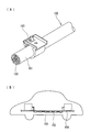
- FIG. 1st Embodiment It is a perspective view which shows the clamp of 1st Embodiment. It is a perspective view which shows the state in the middle of fixing a clamp to the cylinder part of a grommet. It is the schematic which shows the state which attached the clamp fixed to the cylinder part of the grommet to the vehicle body. In 2nd Embodiment, it is the schematic which shows the state which attached the clamp to the vehicle body with another electrical component holding material. In 3rd Embodiment, it is a perspective view which shows the state which fixed the clamp to the small diameter cylindrical part of the grommet inserted and latched in the through-hole of a vehicle body.
- FIG. 1 A prior art example is shown, (A) is the principal part enlarged view of the pipe harness which fixed the clamp, (B) is the schematic which shows the state which attached the pipe harness to the vehicle body. It is a figure which shows a prior art example. It is a figure which shows a prior art example. It is a figure which shows a prior art example. It is a figure which shows a prior art example.
- An exterior corrugated tube 4 is connected to the end of the bent metal pipe 2, and the wire harness 1 drawn from the end of the metal pipe 2 is inserted into the corrugated tube 4 and wired to the inverter.
- a rubber waterproofing grommet 5 (hereinafter referred to as a grommet 5) is externally fitted to a continuous portion between the bent metal pipe 2 and the corrugated tube 4, and the pipe is fitted to the metal pipe 2.
- the clamp 10 is fixed to the outer peripheral surface of the part 5 a and the clamp 10 is fixed to a predetermined position of the vehicle body 30.
- the clamp 10 made of a resin molded product includes a first portion 11 and a second portion 12 each having a pair of semicircular arc-shaped inner surfaces 11 a and 12 a, and includes a first portion 11 and a second portion 12.
- One end side is connected by a thin hinge 13 so as to be freely opened and closed.
- a locked portion 14 and a locking portion 15 which are locked to each other are provided on the divided end side which is the other end side of the first and second portions 11 and 12, a locked portion 14 and a locking portion 15 which are locked to each other are provided.
- the locked portion 14 provided in the first portion is formed of an elastic locked piece continuous in the circumferential direction of the semicircular arc-shaped inner surface 11a, while the locked portion 15 provided in the second portion is engaged by an elastic locked piece. It is formed from a locking claw that locks to the locking portion 14.
- the first portion 11 is provided with a vehicle body fixing portion 16 facing outward.
- the vehicle body fixing portion 16 includes a mounting board 17 provided with bolt holes 18 for
- one continuous grommet fixing projections 19 and 20 are provided in the circumferential direction of the semicircular arc-shaped inner surfaces 11a and 12a of the first portion 11 and the second portion, and the outer periphery of the cylindrical portion 5a of the grommet 5
- One annular recess 6 into which the grommet fixing protrusions 19 and 20 are fitted is provided on the surface.
- one grommet fixing protrusion is provided, but a plurality of grommet fixing protrusions may be provided in parallel. In this case, it is preferable to provide a plurality of annular recesses 6 in parallel.
- the first and second portions 11 and 12 of the clamp 10 are placed on the cylindrical portion 5 a of the grommet 5 so that the grommet fixing protrusions 19 and 20 are fitted into the annular recess 6.
- the locked portions 14 and the locking portions 15 of the second portions 11 and 12 are locked with each other.
- the pipe harness 3 covered with the cylindrical portion 5a is sandwiched between the first and second portions 11 and 12, and the grommet fixing protrusions 19 and 20 of the first and second portions 11 and 12 are the cylindrical portions.
- the grommet 5 can be fitted and fixed to the pipe harness 3 in close contact with the entire circumference of the annular recess 6 of 5a.
- the vehicle body fixing portion 16 provided on the clamp 10 and the vehicle body 30 are fastened with bolts.
- the bolt hole 18 of the mounting board 17 and the bolt hole 31 at a predetermined position of the vehicle body 30 are connected to each other and fastened and fixed with bolts B and nuts N.
- the pipe harness 3 sandwiched between the portions 11 and 12 can be attached to the vehicle body 30.
- the clamp 10 has a function of attaching the pipe harness 3 to the vehicle body 30 and a function of fitting and fixing the grommet 5 to the pipe harness 3, thereby reducing the work man-hours and the number of parts. Moreover, since the clamp 10 of this embodiment has a structure fixed on the cylinder part 5a of the grommet 5 fitted on the pipe harness 3, it is saved without being influenced by the bent pipe shape of the pipe harness 3. The clamp 10 can be stably fixed in a space.
- the vehicle body fixing portion 16 is formed from the mounting board 17 that is bolted to the vehicle body 30. However, the vehicle body fixing portion is formed from a stud bolt or a locking hole that is inserted and locked to the bracket. May be.
- FIG. 4 shows a second embodiment of the present invention.
- the vehicle body fixing portion 41 of another electrical component holding member 40 can be mounted on the vehicle body fixing portion 16 (mounting board 17) of the clamp 10.
- a protector that is externally mounted on the engine harness 7 is used as another electrical component holding member 40.
- the bolt holes 42 provided in the vehicle body fixing portion 41 of the protector are connected to the bolt holes 18 of the mounting board 17 and the vehicle body.
- the bolt 30 is connected to the vehicle body 30 in communication with the 30 bolt holes 31.
- Other points are the same as in the first embodiment.
- FIG. 5 shows a third embodiment of the present invention.
- the grommet 8 for inserting and locking into a through hole (not shown) of the vehicle body is fitted on the bent distal end side of the metal pipe 2 and is closely attached to the metal pipe 2.
- the clamp 10 is fixed to the portion 8a (see FIG. 5).
- the clamp 10 is fixed to the cylindrical portions 5a and 8a of the grommets 5 and 8 that are externally fitted to the bent tip or the tip side of the metal pipe 2. You may fix to the cylinder part of the grommet fitted on the metal pipe which is not carried out.
Landscapes
- Engineering & Computer Science (AREA)
- Mechanical Engineering (AREA)
- General Engineering & Computer Science (AREA)
- Architecture (AREA)
- Civil Engineering (AREA)
- Structural Engineering (AREA)
- Installation Of Indoor Wiring (AREA)
- Supports For Pipes And Cables (AREA)
Abstract
Description
一対の半円弧状内面を有する第1部分と第2部分を薄肉ヒンジで連結すると共に、該第1、第2部分の分割端側に互いに係止する係止部と被係止部を設け、かつ、該第1部分と第2部分のいずれか一方に車体固定部を設け、さらに、前記第1部分および第2部分の半円弧状内面に周方向のグロメット固定用突起を設け、
前記パイプハーネスに外嵌するゴムまたはエラストマーからなるグロメットの筒部に前記第1部分と第2部分とを被せ、該グロメットの筒部の外周面の全周に前記第1部分と第2部分のグロメット固定用突起を押し当て固定する構成としていることを特徴とするクランプを提供している。 In order to solve the above-mentioned problems, the present invention comprises a resin molded product having a function of attaching a pipe harness, in which an electric wire is inserted into a metal pipe, to a vehicle body and a function of fitting and fixing a grommet to the pipe harness. A clamp,
A first portion and a second portion having a pair of semicircular arc-shaped inner surfaces are connected by a thin-walled hinge, and a locking portion and a locked portion that are locked to each other are provided on the divided end sides of the first and second portions, In addition, a vehicle body fixing portion is provided on one of the first portion and the second portion, and further, a circumferential grommet fixing protrusion is provided on the semicircular inner surface of the first portion and the second portion,
The first and second portions of the grommet made of rubber or elastomer that are fitted on the pipe harness are covered with the first portion and the second portion, and the first portion and the second portion are arranged on the entire outer periphery of the cylindrical portion of the grommet. There is provided a clamp characterized in that a grommet fixing projection is pressed and fixed.
または車体の貫通穴に挿入係止するために前記金属パイプの屈曲した先端側に外嵌するグロメットであることが好ましい。 A grommet that fits externally to the pipe harness is a water stop grommet that fits externally to a continuous part of the bent end of the metal pipe and a corrugated tube for electric wire exterior,
Or it is preferable that it is a grommet fitted on the bent front end side of the metal pipe in order to be inserted and locked in the through hole of the vehicle body.
また、前記ワイヤハーネスは、ハイブリッド自動車または電気自動車のバッテリとインバータやインバータとモータを接続するものとし、該ワイヤハーネスを金属パイプに挿通してフロアパネルの下面側に配管すると共に、該金属パイプの先端側を屈曲させてワイヤハーネスを車両内部に引き入れる構造としていることが好ましい。 The clamp of the present invention is preferably a clamp for a pipe harness in which a wire harness routed in a hybrid vehicle or an electric vehicle is inserted into a metal pipe.
The wire harness connects a battery of a hybrid vehicle or an electric vehicle to an inverter or an inverter and a motor. The wire harness is inserted through a metal pipe and is connected to the lower surface side of the floor panel. It is preferable to have a structure in which the distal end side is bent and the wire harness is pulled into the vehicle.
図1乃至図3は第1実施形態を示す。第1実施形態では、ハイブリッド自動車のバッテリとインバータ又はインバータとモータ(図示せず)とを接続する2~3本の電線Wからなるワイヤハーネス1をアルミニウム合金製の金属パイプ2に挿通してパイプハーネス3を形成し、該パイプハーネス3を車体のフロアパネルの下面側(図示せず)に配管すると共に、金属パイプ2の先端側を図2に示すように屈曲させてワイヤハーネス1をエンジンルーム内(図示せず)に引き入れている。屈曲させた金属パイプ2の先端には外装用のコルゲートチューブ4を連続させ、金属パイプ2の先端から引き出したワイヤハーネス1をコルゲートチューブ4に挿通してインバータまで配索している。屈曲させた金属パイプ2の先端とコルゲートチューブ4の先端との連続部にはゴム製の止水用グロメット5(以下、グロメット5という)を外嵌し、金属パイプ2の先端に外嵌する筒部5aの外周面にクランプ10を固定すると共に該クランプ10を車体30の所定位置に固定している。 Hereinafter, embodiments of the present invention will be described with reference to the drawings.
1 to 3 show a first embodiment. In the first embodiment, a wire harness 1 composed of two to three electric wires W connecting a battery and an inverter or an inverter and a motor (not shown) of a hybrid vehicle is inserted into a
まず、図2に示すように、グロメット固定用突起19、20が環状凹部6に嵌め込まれるようにクランプ10の第1、第2部分11、12をグロメット5の筒部5aに被せ、第1、第2部分11、12の被係止部14と係止部15を互いに係止させる。これにより、第1、第2部分11、12の間に筒部5aを被せたパイプハーネス3が挟持されると共に、第1、第2部分11、12のグロメット固定用突起19、20が筒部5aの環状凹部6の全周に押し当て固定され、グロメット5をパイプハーネス3に密着状態で外嵌固定することができる。 Hereinafter, fixing of the
First, as shown in FIG. 2, the first and
なお、本実施形態では車体30とボルト締結する取付基板17から車体固定部16を形成しているが、車体から突設するスタッドボルトまたはブラケットを挿入係止する係止穴から車体固定部を形成してもよい。 That is, the
In the present embodiment, the vehicle
第2実施形態では、クランプ10の車体固定部16(取付基板17)に別の電装品保持材40の車体固定部41も搭載できるようにしている。本実施形態では別の電装品保持材40として例えばエンジンハーネス7に外装するプロテクタとし、図4のように、プロテクタの車体固定部41に設けたボルト穴42を取付基板17のボルト穴18および車体30のボルト穴31に連通して車体30とボルト締結を行っている。
その他の点は第1実施形態と同様としている。 FIG. 4 shows a second embodiment of the present invention.
In the second embodiment, the vehicle
Other points are the same as in the first embodiment.
第3実施形態では、車体の貫通穴(図示せず)に挿通係止するためのグロメット8を金属パイプ2の屈曲した先端側に外嵌し、該金属パイプ2に密着させるグロメット8の小径筒部8aにクランプ10を固定している(図5参照)。 FIG. 5 shows a third embodiment of the present invention.
In the third embodiment, the
2 金属パイプ
3 パイプハーネス
4 コルゲートチューブ
5、8 グロメット
5a 筒部
8a 小径筒部
6 環状凹部
10 クランプ
11 第1部分
12 第2部分
11a、12a 半円弧状内面
13 薄肉ヒンジ
14 被係止部
15 係止部
16、41 車体固定部
17 取付基板
18、31、42 ボルト穴
19、20 グロメット固定用突起
30 車体
40 別の電装品保持材 DESCRIPTION OF SYMBOLS 1
Claims (7)
- 金属パイプ内に電線を挿通しているパイプハーネスを車体に取り付ける機能と、該パイプハーネスにグロメットを外嵌固定する機能とを備えた樹脂成形品からなるクランプであり、
一対の半円弧状内面を有する第1部分と第2部分を薄肉ヒンジで連結すると共に、該第1、第2部分の分割端側に互いに係止する係止部と被係止部を設け、かつ、該第1部分と第2部分のいずれか一方に車体固定部を設け、さらに、前記第1部分および第2部分の半円弧状内面に周方向のグロメット固定用突起を設け、
前記パイプハーネスに外嵌するゴムまたはエラストマーからなるグロメットの筒部に前記第1部分と第2部分とを被せ、該グロメットの筒部の外周面の全周に前記第1部分と第2部分のグロメット固定用突起を押し当て固定する構成としていることを特徴とするクランプ。 It is a clamp made of a resin molded product having a function of attaching a pipe harness through which an electric wire is inserted into a metal pipe to a vehicle body and a function of fitting and fixing a grommet to the pipe harness.
A first portion and a second portion having a pair of semicircular arc-shaped inner surfaces are connected by a thin-walled hinge, and a locking portion and a locked portion that are locked to each other are provided on the divided end sides of the first and second portions, In addition, a vehicle body fixing portion is provided on one of the first portion and the second portion, and further, a circumferential grommet fixing protrusion is provided on the semicircular inner surface of the first portion and the second portion,
The first and second portions of the grommet made of rubber or elastomer that are fitted on the pipe harness are covered with the first portion and the second portion, and the first portion and the second portion are arranged on the entire outer periphery of the cylindrical portion of the grommet. A clamp characterized in that a grommet fixing projection is pressed and fixed. - 前記第1部分と第2部分にそれぞれ設ける前記グロメット固定用突起は、1本または平行に設けた複数本としている請求項1に記載のクランプ。 The clamp according to claim 1, wherein the grommet fixing protrusions provided on the first part and the second part are one or a plurality of parallel protrusions provided in parallel.
- 前記グロメット固定用突起は前記グロメットの筒部の外周面に設けた環状凹部に嵌め込んで取り付けるものとしている請求項1または請求項2に記載のクランプ。 The clamp according to claim 1 or 2, wherein the projection for fixing the grommet is fitted into an annular recess provided on an outer peripheral surface of a cylindrical portion of the grommet.
- 前記パイプハーネスに外嵌するグロメットは、前記金属パイプの屈曲した先端と電線外装用のコルゲートチューブとの連続部に外嵌する止水用グロメット、
または車体の貫通穴に挿入係止するために前記金属パイプの屈曲した先端側に外嵌するグロメットである請求項1乃至請求項3のいずれか1項に記載のクランプ。 A grommet that fits externally to the pipe harness is a water stop grommet that fits externally to a continuous part of the bent end of the metal pipe and a corrugated tube for electric wire exterior,
The clamp according to any one of claims 1 to 3, wherein the clamp is a grommet that is externally fitted to a bent distal end side of the metal pipe so as to be inserted and locked into a through hole of the vehicle body. - 前記第1部分または第2部分に設ける前記車体固定部は、前記車体から突設するスタッドボルトまたはブラケットを挿入係止する係止穴からなり、あるいは、
前記第1部分または第2部分から外方へ取付基板を突設し、該取付基板にボルト穴を設け、前記車体とボルト締結する構成としている請求項1乃至請求項4のいずれか1項に記載のクランプ。 The vehicle body fixing portion provided in the first portion or the second portion is formed of a locking hole for inserting and locking a stud bolt or a bracket protruding from the vehicle body, or
5. The structure according to claim 1, wherein a mounting board is protruded outward from the first part or the second part, a bolt hole is provided in the mounting board, and the bolt is fastened to the vehicle body. Clamp described. - 前記車体固定部の取付基板は別の電装品保持材又はブラケットを搭載できる形状とし、該電装品保持材に設けたボルト穴を前記取付基板のボルト穴と連通し、別の電装品保持材も車体に取り付けられる構成としている請求項1乃至請求項6のいずれか1項に記載のクランプ。 The mounting board of the vehicle body fixing portion is shaped so that another electrical component holding material or bracket can be mounted. The bolt hole provided in the electrical component holding material is communicated with the bolt hole of the mounting board, and another electrical component holding material is also provided. The clamp according to any one of claims 1 to 6, wherein the clamp is attached to a vehicle body.
- ハイブリッド自動車または電気自動車に配索されるワイヤハーネスを金属パイプに挿通しているパイプハーネス用のクランプである請求項1乃至請求項6のいずれか1項に記載のクランプ。 The clamp according to any one of claims 1 to 6, which is a clamp for a pipe harness in which a wire harness routed in a hybrid vehicle or an electric vehicle is inserted into a metal pipe.
Priority Applications (3)
| Application Number | Priority Date | Filing Date | Title |
|---|---|---|---|
| US14/236,975 US9605774B2 (en) | 2011-09-22 | 2012-02-28 | Clamp |
| DE112012003947.5T DE112012003947B4 (en) | 2011-09-22 | 2012-02-28 | clamp |
| CN201280037923.3A CN103717456B (en) | 2011-09-22 | 2012-02-28 | Clip |
Applications Claiming Priority (2)
| Application Number | Priority Date | Filing Date | Title |
|---|---|---|---|
| JP2011-207882 | 2011-09-22 | ||
| JP2011207882A JP5772444B2 (en) | 2011-09-22 | 2011-09-22 | Clamp |
Publications (1)
| Publication Number | Publication Date |
|---|---|
| WO2013042387A1 true WO2013042387A1 (en) | 2013-03-28 |
Family
ID=47914172
Family Applications (1)
| Application Number | Title | Priority Date | Filing Date |
|---|---|---|---|
| PCT/JP2012/054972 WO2013042387A1 (en) | 2011-09-22 | 2012-02-28 | Clamp |
Country Status (5)
| Country | Link |
|---|---|
| US (1) | US9605774B2 (en) |
| JP (1) | JP5772444B2 (en) |
| CN (1) | CN103717456B (en) |
| DE (1) | DE112012003947B4 (en) |
| WO (1) | WO2013042387A1 (en) |
Cited By (1)
| Publication number | Priority date | Publication date | Assignee | Title |
|---|---|---|---|---|
| US20150114680A1 (en) * | 2012-08-01 | 2015-04-30 | Yazaki Corporation | Wire harness exterior member and wire harness |
Families Citing this family (28)
| Publication number | Priority date | Publication date | Assignee | Title |
|---|---|---|---|---|
| US20150204461A1 (en) * | 2011-04-18 | 2015-07-23 | Mordehay Yakir Ben Jacov | Modular Plumbing Bracket |
| JP6028279B2 (en) * | 2012-09-10 | 2016-11-16 | 矢崎総業株式会社 | Wire harness |
| JP6008249B2 (en) * | 2013-07-04 | 2016-10-19 | 住友電装株式会社 | Grommet |
| JP6057176B2 (en) | 2013-08-09 | 2017-01-11 | 住友電装株式会社 | holder |
| JP6048364B2 (en) * | 2013-10-17 | 2016-12-21 | 住友電装株式会社 | Harness equipment |
| CN104373681A (en) * | 2014-08-22 | 2015-02-25 | 浙江保利钢能源科技有限公司 | Reinforcing type supporting pipe clamp |
| JP6229951B2 (en) * | 2014-12-19 | 2017-11-15 | 住友電装株式会社 | Grommet and seal structure using grommet |
| US9920858B2 (en) | 2015-06-30 | 2018-03-20 | Cnh Industrial America Llc | Mounting device for tubular elements |
| JP6519797B2 (en) * | 2015-11-10 | 2019-05-29 | 住友電装株式会社 | Shield conductive path |
| WO2017082893A1 (en) * | 2015-11-11 | 2017-05-18 | Yazaki North America, Inc. | Device and method for securing a wire assembly |
| JP6296134B1 (en) * | 2016-10-11 | 2018-03-20 | マツダ株式会社 | engine |
| JP2018113786A (en) * | 2017-01-11 | 2018-07-19 | 住友電装株式会社 | Protective member |
| US20180320721A1 (en) * | 2017-05-04 | 2018-11-08 | Fisher Controls International Llc | Apparatus to connect a valve stem to an actuator |
| JP6720918B2 (en) * | 2017-05-22 | 2020-07-08 | 豊田合成株式会社 | Pipe holding device |
| CN107834341B (en) * | 2017-09-21 | 2019-02-26 | 北京机械设备研究所 | A kind of round electric connector encapsulating positioning clamping device and its application method |
| CN107947060A (en) * | 2017-12-14 | 2018-04-20 | 北奔重型汽车集团有限公司 | A kind of armored cab harness waterproof sealing system |
| US20190183246A1 (en) * | 2017-12-14 | 2019-06-20 | Marijan BERNIC | Shelving system |
| CN108134251B (en) * | 2017-12-18 | 2019-11-12 | 苏州人为峰软件科技有限公司 | A kind of wire harness clip and engine wiring harness |
| JP6955223B2 (en) * | 2018-08-24 | 2021-10-27 | 住友電装株式会社 | Holder and wire harness |
| DE102019101936A1 (en) * | 2019-01-25 | 2020-07-30 | Ebm-Papst Mulfingen Gmbh & Co. Kg | Cable magazine |
| JP7266014B2 (en) * | 2020-08-07 | 2023-04-27 | 住友電装株式会社 | wire harness unit |
| US11634084B2 (en) | 2021-03-11 | 2023-04-25 | Tyler Edward Goslar | Mount adapter assembly and method of use |
| JP7359806B2 (en) * | 2021-06-10 | 2023-10-11 | 矢崎総業株式会社 | Protector and wire harness |
| CN115706478A (en) * | 2021-08-13 | 2023-02-17 | 余姚市爱优特电机有限公司 | Electric machine, method for assembling such a machine and motor vehicle comprising such a machine |
| CN113844637A (en) * | 2021-09-18 | 2021-12-28 | 贵州新安航空机械有限责任公司 | Wall-through sealing device and method for isolating airplane function frame |
| JP2023078929A (en) * | 2021-11-26 | 2023-06-07 | 住友電装株式会社 | wire harness |
| JP2023168661A (en) * | 2022-05-16 | 2023-11-29 | 株式会社オートネットワーク技術研究所 | wire harness |
| US12036050B1 (en) * | 2023-04-27 | 2024-07-16 | Sure Count Surgical, Llc | Management systems for surgical instruments and items used during surgery |
Citations (3)
| Publication number | Priority date | Publication date | Assignee | Title |
|---|---|---|---|---|
| JPH1126093A (en) * | 1997-07-02 | 1999-01-29 | Yazaki Corp | Shielded connector |
| JP2003056754A (en) * | 2001-08-22 | 2003-02-26 | Oiles Ind Co Ltd | Clamper for wire harness |
| JP2008021425A (en) * | 2006-07-10 | 2008-01-31 | Furukawa Electric Co Ltd:The | Grommet |
Family Cites Families (16)
| Publication number | Priority date | Publication date | Assignee | Title |
|---|---|---|---|---|
| US2248170A (en) * | 1938-08-09 | 1941-07-08 | Robert G Hansen | Adjustable carrying bracket for automobiles |
| US3061253A (en) * | 1960-01-20 | 1962-10-30 | Gen Metals Corp | Line supporting clip |
| DE3126488C2 (en) * | 1981-07-04 | 1983-04-21 | Fa. A. Raymond, 7850 Lörrach | Pipe clamp |
| US4653716A (en) * | 1984-07-05 | 1987-03-31 | Sakaguchi Plastic Industrial Co., Ltd. | Synthetic resin holder |
| DE4039822C1 (en) * | 1990-12-13 | 1992-07-23 | A. Raymond Kg, 7850 Loerrach, De | |
| US6164604A (en) * | 1998-02-03 | 2000-12-26 | Oatey Co. | Pipe clamps |
| DE19840136A1 (en) * | 1998-09-03 | 2000-03-09 | Volkswagen Ag | Bracket and bracket for rigid cables in a vehicle |
| US6145793A (en) * | 1999-04-23 | 2000-11-14 | Interservices, Inc. | Robotic MIG clamp |
| JP3976619B2 (en) | 2002-05-29 | 2007-09-19 | 矢崎総業株式会社 | Long member fixture |
| JP2005069364A (en) | 2003-08-25 | 2005-03-17 | Yazaki Corp | Clip structure |
| JP4560436B2 (en) | 2005-04-22 | 2010-10-13 | 矢崎総業株式会社 | Harness wiring structure |
| JP2010133543A (en) * | 2008-12-08 | 2010-06-17 | Nippon Pop Rivets & Fasteners Ltd | Clamp of corrugated tube |
| JP5267237B2 (en) * | 2009-03-13 | 2013-08-21 | 住友電装株式会社 | Shield pipe clamp |
| JP2010260423A (en) * | 2009-05-01 | 2010-11-18 | San Jidosha Kogyo:Kk | Corner marker lamp |
| JP5360498B2 (en) * | 2010-01-27 | 2013-12-04 | 株式会社ニフコ | Clamp |
| US8973880B2 (en) * | 2012-01-30 | 2015-03-10 | Polaris Industries Inc. | Clamp |
-
2011
- 2011-09-22 JP JP2011207882A patent/JP5772444B2/en not_active Expired - Fee Related
-
2012
- 2012-02-28 WO PCT/JP2012/054972 patent/WO2013042387A1/en active Application Filing
- 2012-02-28 CN CN201280037923.3A patent/CN103717456B/en not_active Expired - Fee Related
- 2012-02-28 DE DE112012003947.5T patent/DE112012003947B4/en not_active Expired - Fee Related
- 2012-02-28 US US14/236,975 patent/US9605774B2/en active Active
Patent Citations (3)
| Publication number | Priority date | Publication date | Assignee | Title |
|---|---|---|---|---|
| JPH1126093A (en) * | 1997-07-02 | 1999-01-29 | Yazaki Corp | Shielded connector |
| JP2003056754A (en) * | 2001-08-22 | 2003-02-26 | Oiles Ind Co Ltd | Clamper for wire harness |
| JP2008021425A (en) * | 2006-07-10 | 2008-01-31 | Furukawa Electric Co Ltd:The | Grommet |
Cited By (2)
| Publication number | Priority date | Publication date | Assignee | Title |
|---|---|---|---|---|
| US20150114680A1 (en) * | 2012-08-01 | 2015-04-30 | Yazaki Corporation | Wire harness exterior member and wire harness |
| US10242768B2 (en) * | 2012-08-01 | 2019-03-26 | Yazaki Corporation | Wire harness exterior member and wire harness |
Also Published As
| Publication number | Publication date |
|---|---|
| JP2013067292A (en) | 2013-04-18 |
| US9605774B2 (en) | 2017-03-28 |
| DE112012003947T5 (en) | 2014-07-17 |
| JP5772444B2 (en) | 2015-09-02 |
| US20140166825A1 (en) | 2014-06-19 |
| CN103717456B (en) | 2016-09-28 |
| DE112012003947B4 (en) | 2020-06-25 |
| CN103717456A (en) | 2014-04-09 |
Similar Documents
| Publication | Publication Date | Title |
|---|---|---|
| JP5772444B2 (en) | Clamp | |
| US7973250B2 (en) | Cable conduit and method of mounting a cable relative to a wall opening | |
| JP5617706B2 (en) | Grommet seal structure | |
| US8624114B2 (en) | Wiring harness | |
| JP5140414B2 (en) | Corrugated clamp | |
| EP2855212B1 (en) | Structure for mounting retrofit part to cladding member | |
| US20150107894A1 (en) | Harness device | |
| KR101037309B1 (en) | Outer protective assembly of wire harness for door and arranging structure of wire harness for door | |
| JP5644698B2 (en) | Grommet | |
| JP6358141B2 (en) | Wire harness protector fixing structure | |
| JP2013070483A (en) | Waterproof structure for terminal of wire harness | |
| WO2013031261A1 (en) | Protector and attachment structure for protector | |
| US9561757B2 (en) | Wiring harness | |
| KR20190074526A (en) | Wiring harness fastening apparatus using band cable equipped with rotation preventing function | |
| JP2003009362A (en) | Grommet with resin inner sleeve for fixing connector | |
| JP5765085B2 (en) | Grommet | |
| JP5550399B2 (en) | Grommet for wire harness | |
| JP5799937B2 (en) | Grommet and wiring harness wiring structure | |
| JP2005065354A (en) | Structure for fixing grommet to wire harness | |
| JP5765101B2 (en) | Grommet | |
| JP2011236940A (en) | Structure for bolt fixing part | |
| JP2004236447A (en) | Cabling structure for wire harness | |
| JP5024091B2 (en) | Grommet mounting structure | |
| JP5729166B2 (en) | Pipe harness body mounting structure | |
| JP5215201B2 (en) | Grommet |
Legal Events
| Date | Code | Title | Description |
|---|---|---|---|
| 121 | Ep: the epo has been informed by wipo that ep was designated in this application |
Ref document number: 12833063 Country of ref document: EP Kind code of ref document: A1 |
|
| WWE | Wipo information: entry into national phase |
Ref document number: 14236975 Country of ref document: US |
|
| WWE | Wipo information: entry into national phase |
Ref document number: 1120120039475 Country of ref document: DE Ref document number: 112012003947 Country of ref document: DE |
|
| 122 | Ep: pct application non-entry in european phase |
Ref document number: 12833063 Country of ref document: EP Kind code of ref document: A1 |