WO2013039042A1 - 再生装置、再生方法、配信装置、配信システム、再生プログラムおよび記録媒体 - Google Patents
再生装置、再生方法、配信装置、配信システム、再生プログラムおよび記録媒体 Download PDFInfo
- Publication number
- WO2013039042A1 WO2013039042A1 PCT/JP2012/073109 JP2012073109W WO2013039042A1 WO 2013039042 A1 WO2013039042 A1 WO 2013039042A1 JP 2012073109 W JP2012073109 W JP 2012073109W WO 2013039042 A1 WO2013039042 A1 WO 2013039042A1
- Authority
- WO
- WIPO (PCT)
- Prior art keywords
- distribution
- playback
- configuration data
- group
- reproduction
- Prior art date
Links
Images


Classifications
-
- H—ELECTRICITY
- H04—ELECTRIC COMMUNICATION TECHNIQUE
- H04N—PICTORIAL COMMUNICATION, e.g. TELEVISION
- H04N21/00—Selective content distribution, e.g. interactive television or video on demand [VOD]
- H04N21/40—Client devices specifically adapted for the reception of or interaction with content, e.g. set-top-box [STB]; Operations thereof
- H04N21/43—Processing of content or additional data, e.g. demultiplexing additional data from a digital video stream; Elementary client operations, e.g. monitoring of home network or synchronising decoder's clock; Client middleware
- H04N21/4302—Content synchronisation processes, e.g. decoder synchronisation
- H04N21/4307—Synchronising the rendering of multiple content streams or additional data on devices, e.g. synchronisation of audio on a mobile phone with the video output on the TV screen
- H04N21/43072—Synchronising the rendering of multiple content streams or additional data on devices, e.g. synchronisation of audio on a mobile phone with the video output on the TV screen of multiple content streams on the same device
-
- H—ELECTRICITY
- H04—ELECTRIC COMMUNICATION TECHNIQUE
- H04L—TRANSMISSION OF DIGITAL INFORMATION, e.g. TELEGRAPHIC COMMUNICATION
- H04L65/00—Network arrangements, protocols or services for supporting real-time applications in data packet communication
- H04L65/60—Network streaming of media packets
- H04L65/61—Network streaming of media packets for supporting one-way streaming services, e.g. Internet radio
- H04L65/611—Network streaming of media packets for supporting one-way streaming services, e.g. Internet radio for multicast or broadcast
-
- H—ELECTRICITY
- H04—ELECTRIC COMMUNICATION TECHNIQUE
- H04N—PICTORIAL COMMUNICATION, e.g. TELEVISION
- H04N21/00—Selective content distribution, e.g. interactive television or video on demand [VOD]
- H04N21/40—Client devices specifically adapted for the reception of or interaction with content, e.g. set-top-box [STB]; Operations thereof
- H04N21/43—Processing of content or additional data, e.g. demultiplexing additional data from a digital video stream; Elementary client operations, e.g. monitoring of home network or synchronising decoder's clock; Client middleware
- H04N21/44—Processing of video elementary streams, e.g. splicing a video clip retrieved from local storage with an incoming video stream, rendering scenes according to MPEG-4 scene graphs
- H04N21/44004—Processing of video elementary streams, e.g. splicing a video clip retrieved from local storage with an incoming video stream, rendering scenes according to MPEG-4 scene graphs involving video buffer management, e.g. video decoder buffer or video display buffer
-
- H—ELECTRICITY
- H04—ELECTRIC COMMUNICATION TECHNIQUE
- H04N—PICTORIAL COMMUNICATION, e.g. TELEVISION
- H04N21/00—Selective content distribution, e.g. interactive television or video on demand [VOD]
- H04N21/40—Client devices specifically adapted for the reception of or interaction with content, e.g. set-top-box [STB]; Operations thereof
- H04N21/43—Processing of content or additional data, e.g. demultiplexing additional data from a digital video stream; Elementary client operations, e.g. monitoring of home network or synchronising decoder's clock; Client middleware
- H04N21/442—Monitoring of processes or resources, e.g. detecting the failure of a recording device, monitoring the downstream bandwidth, the number of times a movie has been viewed, the storage space available from the internal hard disk
- H04N21/44209—Monitoring of downstream path of the transmission network originating from a server, e.g. bandwidth variations of a wireless network
-
- H—ELECTRICITY
- H04—ELECTRIC COMMUNICATION TECHNIQUE
- H04N—PICTORIAL COMMUNICATION, e.g. TELEVISION
- H04N21/00—Selective content distribution, e.g. interactive television or video on demand [VOD]
- H04N21/40—Client devices specifically adapted for the reception of or interaction with content, e.g. set-top-box [STB]; Operations thereof
- H04N21/45—Management operations performed by the client for facilitating the reception of or the interaction with the content or administrating data related to the end-user or to the client device itself, e.g. learning user preferences for recommending movies, resolving scheduling conflicts
- H04N21/462—Content or additional data management, e.g. creating a master electronic program guide from data received from the Internet and a Head-end, controlling the complexity of a video stream by scaling the resolution or bit-rate based on the client capabilities
- H04N21/4622—Retrieving content or additional data from different sources, e.g. from a broadcast channel and the Internet
Definitions
- the present invention relates to a reproducing apparatus and a reproducing method for acquiring a group of contents constituting distribution data through a plurality of transmission paths.
- the present invention also relates to a distribution apparatus that distributes at least a part of distribution data.
- the present invention relates to a distribution system including the playback device, a playback program that causes a computer to function as such a playback device, and a computer-readable recording medium on which such a playback program is recorded.
- NGN Next Generation Network
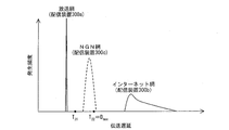
- FIG. 15 is a graph showing the distribution of transmission delay in each network. As can be seen from FIG. 15, the amount of transmission delay assumed at the time of transmission differs in each network. That is, the magnitude of the time lag that occurs depends on which network the video is received from.
- the playback device needs to buffer each video so that it can be played back in a synchronized state.
- Non-Patent Document 1 is an RFC document in which technical specifications of a real-time streaming protocol (RTSP) are described.
- RTSP real-time streaming protocol
- a receiving apparatus that supports RTSP can determine the buffering time according to the jitter value by acquiring the jitter value from the server using the GET_PARAMETER method described in Non-Patent Document 1.
- the present invention has been made in view of the above problems, and its main purpose is to acquire a group of contents constituting a program (generally, distribution data) to be synchronously reproduced through a plurality of transmission paths. Is to realize a playback apparatus that can start playback of a program quickly.
- a program generally, distribution data
- the playback device is a configuration data group composed of configuration data distributed from each of a plurality of distribution devices, and is configured for synchronous playback that constitutes distribution data.
- an acquisition unit that acquires a data group, and a delay time that occurred when the configuration data was acquired from the distribution device in the past, and recorded in the storage medium as a history for each distribution device
- the reference means for referring to the delay time being recorded, as a buffering period necessary for reproducing the configuration data acquired from the distribution device, is recorded as a history about the distribution device
- Derivation means for deriving a period having a length corresponding to the magnitude of the delay time referred to by the reference means, and the distribution device for each of the plurality of distribution devices And replaying the distribution data after buffering the constituent data being acquired from the predetermined period, and the longest buffering period among the buffering periods derived by the deriving means is the predetermined period.
- the playback unit buffers the configuration data group (for example, the content group or the component group) for the length of time corresponding to the maximum delay time, and then the program.
- the configuration data group for example, the content group or the component group
- the buffering time is almost as short as necessary.
- the playback unit determines the buffering time with reference to the transmission delay recorded as a history in the storage medium of the playback device, the buffering time can be determined earlier than before.
- the reproducing apparatus can quickly reproduce the program in a state where the contents are synchronized.
- the playback method is a configuration data group composed of configuration data distributed from each of a plurality of distribution apparatuses, and is used for the configuration that is to be synchronized and reproduced that constitutes the distribution data
- a reference process for referring to the delay time being recorded and a buffering period necessary for reproducing the configuration data acquired from the distribution device is recorded as a history relating to the distribution device.
- the reproduction method according to the present invention has the same operational effects as the reproduction apparatus according to the present invention.
- the playback device plays back a program when acquiring a group of contents that constitute a program (generally, distribution data) to be played back synchronously through a plurality of transmission paths. There is an effect that it can be started quickly.
- a program generally, distribution data
- FIG. 3 is a flowchart showing an operation example until the playback apparatus of FIG. 1 starts playback of a program.
- FIG. 4 is a diagram exemplifying a buffering allowable time set when the reproducing apparatus of FIG. 1 performs the operation shown in the flowchart of FIG. 3 on a distribution curve graph relating to transmission delay.
- FIG. 9 is a diagram exemplifying a necessary buffering time calculated when the reproducing apparatus of FIG. 1 performs the operations shown in the flowcharts of FIGS.
- FIG. 3 is a flowchart showing an operation example until the playback apparatus of FIG. 1 starts playback of a program.
- FIG. 7 is a diagram exemplifying buffering allowable time set when the reproducing apparatus of FIG. 1 performs the operation shown in the flowchart of FIG. 6 on a distribution curve graph regarding transmission delay.
- 3 is a flowchart illustrating an example of an operation of reproducing video content that can be reproduced at a multi-angle by the reproduction apparatus of FIG. 1.
- FIG. 9 is a diagram schematically showing a playback start timing and a playback speed of each package described later when the playback device of FIG. 1 performs the operation shown in the flowchart of FIG. 8.
- the range of values that can be taken by the NW identifier included in a part of the contents of the package descriptor is shown in (a), and history information of transmission delay generated for each NW identifier (or a combination of a broadcast station and an NW identifier) is shown. It is the figure typically illustrated in (b). It is the figure which showed the graph of the distribution curve regarding transmission delay for every kind of transmission network.
- Embodiment 1 The distribution system according to the present embodiment will be described with reference to FIGS.
- a distribution system is a distribution system that distributes a program composed of a plurality of contents (configuration data) to a playback apparatus using three distribution apparatuses.
- the three distribution devices include a distribution device that distributes content via a broadcast network, a distribution device that distributes content via an Internet network, and a distribution device that distributes content via an NGN network.
- the program is composed of content that must be played back and content that can be played back, and includes at least one content that must be played back.
- FIG. 2 shows a screen structure of a binary relay program displayed on the screen of the display device.
- content 1 indicates main video content
- content 2 indicates sub video content
- content 3 indicates BML content.
- Content is composed of one or more components [configuration data] such as video, audio, subtitles, software, and advertisements.
- each layer base layer, enhancement layer 1, enhancement layer 2, etc.
- the main sound and the sub sound can be made into separate components.
- the content that is required to be reproduced includes at least one component that is required to be reproduced, and the content that is optional to be reproduced does not include the component that is essential to reproduce.
- a component that can be reproduced may be included in any content that must be reproduced and any content that is reproduced. In the example of FIG.
- content 1 includes components of main audio a11 (reproduction optional), sub audio a12 (reproduction optional), and video v1 (reproduction required), and content 2 is main audio a21 (reproduction optional), Each component includes sub audio a22 (playback optional) and video (playback optional).
- the BML content (content 3) is composed of BML data d1 (playback arbitrary) which is only one component.
- the playback device when receiving a program playback instruction, starts playback of content that is required to be played back that constitutes the program.
- the playback device starts playback of content that can be played back that constitutes a program if the content is set to be played back.
- the playback device can be set to play back all the components constituting the content to be played back, or to play back only some of the components selected by the user.
- the playback device can be set to play back all the components constituting the content to be played back, or to play back only some of the components selected by the user.
- at least some of the components that make up the content are defined as components that must be played back. The component is supposed to play.
- FIG. 1 is a diagram showing a configuration of a distribution system and a configuration of a playback device included in the distribution system according to an embodiment of the present invention.
- the distribution system includes a playback device 100, a display device 200, and three distribution devices 300a to 300c.
- the playback device 100 determines a playback target component group from among the content groups constituting the playback target program, and The reproduction target is obtained by acquiring from the distribution devices 300a to 300c for distributing the components.
- Each distribution device 300a to 300c does not distribute each component individually, but distributes each component in a unit called a package in which a plurality of components are multiplexed. Therefore, for each package, the playback device 100 performs playback by acquiring a package including the playback target component from the component group from the distribution device corresponding to the package.
- information regarding each package is, for example, a specific information whose access destination information is known when a program playback instruction is received. You may receive from a delivery apparatus.
- the playback device 100 the display device 200, and the distribution devices 300a to 300c will be described.
- the distribution apparatus 300a is a distribution apparatus that distributes packaged components via a broadcast network so that the reproduction apparatus 100 can receive the reproduction target component.
- the distribution device 300b is a distribution device that distributes a packaged component via the Internet network so that the reproduction device 100 can receive the reproduction target component.
- the distribution apparatus 300c is a distribution apparatus that distributes components packaged via the NGN network so that the reproduction apparatus 100 can receive the reproduction target component.
- the playback apparatus 100 includes a streaming control unit 110, a playback unit 120, a reception buffer 130, an HDD (Hard Disk Drive) 140, a nonvolatile memory 150, a network I / F 160, and a tuner unit 170.
- a streaming control unit 110 As shown in FIG. 1, the playback apparatus 100 includes a streaming control unit 110, a playback unit 120, a reception buffer 130, an HDD (Hard Disk Drive) 140, a nonvolatile memory 150, a network I / F 160, and a tuner unit 170.
- HDD Hard Disk Drive
- the streaming control unit 110 controls the network I / F 160 and the tuner unit 170 so as to acquire the package including the playback target component from any of the distribution apparatuses 300a to 300c based on the information about the package.
- the components included in each package are buffered in the reception buffer 130.
- the streaming control unit 110 receives the reception time when the package is received from the distribution device and the time stamp (distribution time) given to the package for each of the distribution devices 300a to 300c.
- the transmission delay (hereinafter, “transmission delay” is used in this sense), which is the difference from), is recorded in the transmission delay history table 155 in the nonvolatile memory 150. Even if the transmission delay is recorded for all the packets for each transmission unit (for example, IP packet or TS packet) of the package in the network between the reproduction apparatus 100 and the distribution apparatuses (distribution apparatuses 300a to 300c).
- a configuration may be adopted in which the transmission delay is recorded only for packets received at that time every predetermined period among all packets.
- the playback unit 120 refers to the transmission delay history table 155 to obtain a buffering period until each component is played back.
- the reproduction unit 120 sequentially reproduces the data of each component buffered in the reception buffer 130 after the above period has elapsed after the buffering is started.
- a video signal and an audio signal generated by the reproduction are supplied to the display device 200 via an HDMI cable (not shown) or the like.
- the reception buffer 130 is a buffer in which data of each component received from the distribution device is buffered.
- the HDD 140 is a recording medium that is a recording destination of each component when recording.
- Nonvolatile memory 150 is a flash memory that holds a transmission delay history table 155.
- the network I / F 160 is a network I / F for receiving packages from the distribution apparatuses 300b and 300c.
- the tuner unit 170 is a tuner for receiving a broadcast wave carrying a package distributed by the distribution device 300a.
- Display device 200 The display device 200 displays the video represented by the video signal supplied from the playback device 100 on the screen, and outputs the sound represented by the audio signal supplied from the playback device 100 from the speaker.
- FIG. 3 is a flowchart showing the operation of the playback apparatus 100 until the playback of the playback target program is started.
- FIG. 4 shows an allowable buffering time set when the reproducing apparatus 100 performs the above operation on a coordinate plane showing a distribution curve regarding transmission delay generated when acquiring a package from the distribution apparatus for each distribution apparatus.
- FIG. FIG. 5 is a diagram exemplifying the necessary buffering time set for the corresponding package by the playback device 100 on the coordinate plane showing the distribution curve graph regarding the transmission delay generated when the package is acquired from the distribution device. It is.
- a package including a component that must be played is generally distributed from the distribution apparatus 300a via a broadcasting network with the smallest transmission delay.
- a program to be played is composed of one playback-required video content, and the video content is divided into a base layer video component (required playback) that is HD video and an extension layer video component (required playback) that is 4K video by scalable coding.
- the package 1 is composed of the base layer video component alone and the package 2 is composed of the enhancement layer video component alone, the package 1 is from the distribution device 300a and the package 2 is from any of the distribution devices 300b and 300c. Shall be delivered.
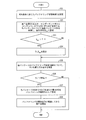
- the playback device 100 sets a predetermined buffering allowable time T (predetermined allowable time) according to a playback condition (whether live playback or recording playback) (S1). ).
- T predetermined buffering allowable time
- the playback unit 120 sets T 11 as the value of T in the case of live playback, and sets T 12 as the value of T in the case of recording playback.
- the playback unit 120 determines whether or not D ⁇ T is satisfied for the buffering required time D of each package including at least a part of the playback target component group (S2). Specifically, the playback unit 120 determines the buffering required time D of each package based on the delay time that occurred when the package was acquired in the past from the distribution device corresponding to the package. As the buffering required time D, the maximum delay time recorded in the corresponding record of the transmission delay history table 155 may be used. However, in the case of a network with a large transmission delay fluctuation such as the Internet, the buffering required time is There is a growing problem. In general, in the case of video content, even if some data loss occurs due to a transmission error or the like, the influence on reproduction is very small.
- the reproduction quality of the content can be maintained at a predetermined reproduction quality or higher.
- the delay time corresponding to the entry of 5% from the largest of the delay times recorded in the corresponding record of the transmission delay history table 155 is set as the buffering required time D. Good.
- the playback unit 120 randomly selects 100 delay times from among a sufficient number of delay times recorded in the corresponding records of the transmission delay history table 155, and sets the fifth delay time from the largest to the D The same effect can be expected even if set as. Then, the reproducing unit 120 determines whether D ⁇ T is satisfied for each D set in this way.
- step S2 when the playback condition is not live playback (NO in S3), the playback unit 120 starts recording processing of each content, starts playback after the recording is completed, and ends the processing. On the other hand, if the playback condition is live playback (YES in S3), the process proceeds to S4.
- step S4 the reproducing unit 120 sets the maximum D satisfying D ⁇ T among the buffering required time D of each package as the value of the buffering time Tb (predetermined period).
- the playback unit 120 sets D of the package 1 to the buffering time Tb. Set as.
- step S4 the streaming control unit 110 acquires a package including a component to be played back from each distribution device and sequentially buffers it in the reception buffer 130. After Tb has elapsed from the start of buffering, the streaming control unit 110 performs buffering. Playback of each component is started (S5), and the process ends.
- the operation example 1 of the playback apparatus 100 has been described above.
- the required buffering time D of each package set in step S2 is the necessity of buffering of the package when the playback apparatus 100 plays back a component included in the package.
- the value is such that reproduction can be started if buffering is performed only for time D.
- the playback device 100 determines the buffering time Tb by referring to the transmission delay history table 155, and therefore can quickly determine the buffering time Tb.
- the playback device 100 can quickly start playback synchronized with each component (content) with a minimum buffering time.
- a plurality of contents or components may be exclusively played back by a user operation.
- this includes a program configuration that can be played back by switching between multiple angles depending on a plurality of video contents, and a program configuration that can be played back by switching between a plurality of audio components or subtitle components corresponding to a plurality of languages.
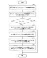
- FIG. 6 is a flowchart showing the operation of the playback apparatus 100 until the playback of the program is started.
- FIG. 7 shows an allowable buffering time set when the reproducing apparatus 100 performs the above operation on a coordinate plane showing a distribution curve regarding a transmission delay generated when acquiring a package from the distribution apparatus for each distribution apparatus.
- the playback unit 120 like S1 in the first operation example, has a buffering allowable time T (predetermined in accordance with playback conditions (whether live playback or recording playback)). Is set (S21). For example, the reproducing unit 120 sets T 21 shown in FIG. 7 as the value of the buffering allowable time T.
- the reproducing unit 120 sets the maximum D as the value of D max among the buffering required time D of each package including at least a part of the component group that is mandatory to reproduce (S22).
- D max when the user selects the package 2 (video content of viewpoint 2) distributed from the distribution device 300c is shown.
- the reproducing apparatus 100 is indispensable to reproduce by updating the buffering allowable time T to a large value. Playback of each component can be started. That is, the playback device 100 can always play back the video content of the viewpoint 2 selected by the user with a minimum buffering delay regardless of the buffering allowable time T.
- FIG. 8 is a flowchart showing the operation of the playback apparatus 100 that plays back video content.
- FIG. 9 schematically illustrates a playback mode of the playback device 100 after the distribution device starts buffering of components included in each package for a package that satisfies D ⁇ T and a package that does not satisfy D ⁇ T. It is a figure.
- This operation example is an operation example in which all packages (that is, all contents and all components) constituting the program are acquired from the distribution device and played back regardless of the size of the buffering allowable time T.
- Such an operation is performed, for example, when the target program is configured by scalable encoded video content, and the package 1 including the HD video component of the base layer is acquired from the distribution device 300a via the broadcast network, There is a case where the package 2 including the 4K video component of the enhancement layer is acquired from the distribution apparatus 300b via the NGN network.
- the playback unit 120 like S1 in the first operation example, has a buffering allowable time T (predetermined in accordance with playback conditions (whether live playback or recording playback)). Is set (S41). For example, the reproducing unit 120 sets T 11 shown in FIG. 4 as the value of the buffering allowable time T.
- step S42 when the playback condition is not live playback (NO in S42), the playback unit 120 starts recording processing of each content, starts playback after completion of recording, and ends the processing. On the other hand, if the playback condition is live playback (YES in S42), the process proceeds to S44.
- step S44 as in step S4, the reproducing unit 120 sets the maximum D satisfying D ⁇ T among the buffering required time D of each package as the value of the buffering time Tb.
- D of the package 1 is set as the value of the buffering time Tb.
- D c is a period during which each component included in the package satisfying D ⁇ T is reproduced at S ( ⁇ 1) times speed, and is set in advance in the reproducing apparatus 100.
- D max is a value equal to the largest D of the buffering required time D of each package to be reproduced.
- the streaming control unit 110 acquires each component to be reproduced from the distribution devices 300a and 300b and sequentially buffers the components in the reception buffer 130. Then, after Tb has elapsed from the start of buffering, the playback unit 120 starts playback at S-times speed for each component included in the package satisfying D ⁇ T among the buffered components ( S46). In the above example, the playback unit 120 starts playback of the HD video included in the package 1 at S-times speed after Tb has elapsed from the start of buffering.
- the playback unit 120 starts normal playback of other components (each component included in a package that does not satisfy D ⁇ T) when D c has elapsed from the start of playback at S-times speed in step S46. Also, the playback unit 120 switches to normal playback for each component that was played back at S times at this time (S47). In the above example, the playback unit 120 starts playback at 1 ⁇ speed of the HD video included in the package 1 and the 4K video included in the package 2 after Tb + D c has elapsed from the start of buffering.
- FIG. 9 shows a playback mode of the playback device when the playback device 100 plays back a program according to the operation example 3.
- the playback device 100 is in a state in which the head portion of each component of the package that does not satisfy D ⁇ T can be played back when D max has elapsed since the start of buffering. .
- the playback apparatus 100 plays back the portion of S ⁇ (D max ⁇ Tb) from the beginning of each component at this point in time for a package that satisfies D ⁇ T, playback of a package that does not satisfy D ⁇ T. Is started at this point, it is played back in a state where it is not synchronized with the package satisfying D ⁇ T.
- the playback device 100 starts playback in a state in which each component (content) that can be played back by buffering within the buffering allowable time T is preferentially synchronized, and thereafter All components (contents) constituting the program can be reproduced in a synchronized state.
- the streaming control unit 110 of the playback device 100 acquires the component group that is to be played back in synchronization with each other by acquiring some components from each distribution device that is the acquisition destination. ing.
- the playback unit 120 of the playback device 100 transmits, for each delivery device, a transmission delay that occurs when acquiring a component from the delivery device, which is recorded in the transmission delay history table 155 of the memory 150 attached to the playback device 100.
- the playback unit 120 derives the minimum buffering time necessary for streaming playback from the actual value of the transmission delay of the package delivered from each delivery device in the past.
- the playback unit 120 starts playback of the program after buffering the component group for the buffering time.
- the playback unit 120 starts playback of the program after buffering the component group for a minimum length of time required for streaming playback, so that each component can be played back in a synchronized state.
- the playback unit 120 determines the buffering time with reference to the transmission delay history table 155 of the memory 150 attached to the playback device 100, so that the buffering time can be determined earlier than in the past.
- the playback device 100 can quickly play back the program in a state where the content is synchronized.
- FIG. 10 is a diagram illustrating a configuration of a distribution system according to the present embodiment and a configuration of a playback device included in the distribution system.
- the distribution system according to the present embodiment includes a large number of distribution apparatuses instead of three.
- the distribution system according to the present embodiment includes a distribution device 300a ′ for distributing a package via a broadcast network and a plurality of distribution devices 300b for distributing a package via an Internet network.
- a content delivery network (CDN) distribution system including a plurality of distribution apparatuses 300c that distribute packages via the NGN network.
- the playback device 100 records the transmission delay generated when acquiring the package from the distribution device for each group, not for each distribution device.
- each distribution device belongs to one of a group of one distribution device 300a ', a group composed of a plurality of distribution devices 300b, and a group composed of a plurality of distribution devices 300c.
- a network identifier (NW identifier) described later with reference to FIG. 14 is used as an identifier for identifying the group.
- the configuration of the playback device 100 ′ and the distribution device 300 a ′ according to the present embodiment will be described with reference to FIG. 10. Since the distribution device 300b, the distribution device 300c, and the display device 200 have already been described in the first embodiment, the description thereof is omitted here.
- the playback apparatus 100 ′ includes a streaming control unit 110 ′, a playback unit 120 ′, a reception buffer 130, an HDD (hard disk drive) 140, a nonvolatile memory 150, a network I / F 160, and a tuner unit 170.
- a streaming control unit 110 ′ the playback unit 120 ′
- a reception buffer 130 the playback unit 120 ′
- an HDD (hard disk drive) 140 the playback apparatus 100 ′ includes a streaming control unit 110 ′, a playback unit 120 ′, a reception buffer 130, an HDD (hard disk drive) 140, a nonvolatile memory 150, a network I / F 160, and a tuner unit 170.
- HDD hard disk drive
- the streaming control unit 110 ', the playback unit 120', and the nonvolatile memory 150 ' will be described.
- the reception buffer 130, HDD (hard disk drive) 140, network I / F 160, and tuner unit 170 have the same configurations as those in the first embodiment, and thus description thereof is omitted.
- streaming control unit 110 ′ When the streaming control unit 110 ′ receives a program playback instruction, the streaming control unit 110 ′ accesses the memory 150 ′ and meta information (program descriptor, content descriptor, component descriptor, and package descriptor) necessary for playing the program. ). Note that the playback device 100 ′ acquires the meta information regarding various programs while the tuner unit 170 receives broadcast waves, and stores the meta information in the memory 150 ′.
- meta information program descriptor, content descriptor, component descriptor, and package descriptor
- the streaming control unit 110 ′ acquires the component from any one of a number of distribution devices for the package including each component constituting the content group to be reproduced based on the referenced meta information.
- the network I / F 160 and the tuner unit 170 are controlled, and the data of the playback target component included in each received package is buffered in the reception buffer 130.
- the streaming control unit 110 ′ records, in the transmission delay history table 155 ′ in the nonvolatile memory 150 ′, the transmission delay generated when the package is acquired from the distribution device for each distribution device during reception of the program to be played. To do. Specifically, the streaming control unit 110 'records the transmission delay in a different record in the transmission delay history table 155' for each group to which the distribution apparatus belongs. Note that the transmission delay is recorded for all packets for each transmission unit (for example, IP packet or TS packet) of the package in the network between the playback device 100 ′ and the distribution devices (distribution devices 300a to 300c). Alternatively, the transmission delay may be recorded only for the packets received at that time for every predetermined period among all the packets.
- the transmission delay may be recorded only for the packets received at that time for every predetermined period among all the packets.
- the reproduction unit 120 ′ refers to the transmission delay history table 155 ′ to obtain a buffering period before reproducing the reproduction target program.
- the reproduction unit 120 ′ sequentially reproduces the data of each component buffered in the reception buffer 130 after the above period has elapsed since the start of buffering.
- a video signal and an audio signal generated by the reproduction are supplied to the display device 200 via an HDMI cable (not shown) or the like.
- Nonvolatile memory 150 ′ is a flash memory that holds a transmission delay history table 155 ′.
- the distribution apparatus 300a ′ is a distribution apparatus that distributes a component packaged via a broadcast network on a broadcast wave so that the reproduction apparatus 100 can receive the reproduction target component.
- the distribution device 300a ′ distributes the above-described meta information of each program on a broadcast wave.
- FIG. 11 is a diagram showing a specific example of various package groups constituting the meta information.
- the meta information is composed of one program descriptor, one or more content descriptors, one or more component descriptors, and one or more package descriptors.
- the program descriptor is a descriptor indicating what kind of content the program is composed of.
- the program descriptor is composed of three contents of contents 1 to 3.
- the program descriptor can include information indicating whether content is indispensable for reproduction or content for reproduction.
- the content descriptor is a descriptor indicating what kind of component the content is composed of.
- the content descriptor can also include information indicating whether playback is an essential component or playback is an optional component.
- the content descriptor of content 2 indicates that it is composed of two components, component 2 and component 3. A specific example of the content descriptor is shown in FIG.
- the content descriptor includes an allowable synchronization error, an allowable error rate, the number of components included in the content, and an identifier of the component included in the content.
- “Allowable error rate e” is the allowable error rate of the target content set by the broadcaster for each content.
- the required buffering time D is determined based on the allowable error rate determined by the playback device, regardless of the type of content. However, in the distribution system of the present embodiment, the broadcaster The required buffering time D is determined on the basis of the allowable error rate for each content set by.
- the allowable error rate e is reduced for content that causes fatal deterioration in reproduction quality such as BML content, and a relatively large amount of data loss such as video content. If the allowable error rate e is set large for content that can easily maintain a certain reproduction quality even if the reproduction occurs, the reproduction apparatus can derive a more appropriate buffering required time D. is there.
- “Allowable synchronization error” indicates the maximum synchronization error (maximum reproduction delay of the target content with respect to the reference time) that is allowed when the target content is played back simultaneously with other content constituting the program to be played back. Yes.
- the reproduction delay of the target content with respect to the reference time is allowed up to 100 msec.
- the allowable synchronization error of the BML content can be set to be relatively large.
- the component descriptor includes an allowable synchronization error, an allowable error rate, and a codec.
- “Allowable error rate e” indicates the allowable error rate of the target component, and is described when a different allowable error rate is set for each component constituting the content.
- “Allowable synchronization error” indicates the maximum synchronization error allowed when the target component is played back simultaneously with other content and other components constituting the program to be played back. This is described in the case where different allowable synchronization errors are set.
- “Codec” indicates a video codec or audio codec when the component is video or audio.
- the package descriptor is a descriptor indicating what kind of component the package is composed of. Specific examples of package descriptors are shown in FIGS. 13 (a) and 13 (b).
- the package descriptor includes the number of components included in the package and the identifier of the component included in the package. Further, the package descriptor includes one or more groups of information in which a distribution period in which each component is distributed, access destination information (URL) for acquiring each component in the distribution period, and an NW identifier are associated with each other. It is out.
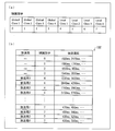
- FIG. 14 (a) shows possible values of the NW identifier.
- the NW identifier can take eight values from 0 to 7.
- NW identifiers are classified into NW identifiers assigned to distribution devices shared by a plurality of broadcasting stations (broadcasting companies) and NW identifiers assigned to distribution devices used individually in each broadcasting station.
- the former identifier is referred to as Global Class identifier
- the latter identifier is referred to as Local Class identifier.
- four identifiers from 0 to 3 are Global Class identifiers
- four identifiers from 4 to 7 are Local Class identifiers.
- FIG. 14B shows an example of the content of the transmission delay history table 155 ′ that is updated when the streaming control unit 110 ′ acquires the package and that the reproduction unit 120 ′ refers to determine the buffering required time D. An example is shown.
- the transmission delay history table 155 ′ holds the transmission delay that occurred in the past for each NW identifier for the Global class identifier, and the NW identifier, broadcasting station, and the local class identifier. Each combination holds a transmission delay that occurred in the past.
- the streaming control unit 110 ′ selects content and components that must be reproduced based on the program descriptor and the content descriptor. In addition, based on the content of the playback instruction by the user, the component to be played back is determined from the content and components that can be played back.
- the streaming control unit 110 refers to each package descriptor to recognize which package the component is included in for each determined component.
- the streaming control unit 110 ′ refers to the URL described in the package descriptor related to the package for each package including at least one of the one or more components to be reproduced, and acquires the package.
- the package descriptor is the package descriptor shown in FIG. 13A and the current time is within the distribution period 1
- the streaming control unit 110 ′ has a URL of rtsp: // Acquire the package by accessing the distribution device represented by exampl1.com/program1/package1/.
- the streaming control unit 110 ′ records the difference between the reception time when the package is received and the time stamp (distribution time) given to the package as a transmission delay in the transmission delay history table 155 ′. Specifically, the streaming control unit 110 ′ refers to the NW identifier associated with the URL referred to obtain the package, and transmits a transmission delay to the record corresponding to the referenced NW identifier in the transmission delay history table 155 ′. Record as.
- the playback unit 120 ′ refers to the NW identifier described in the package descriptor of the package and records in the past the record corresponding to the referenced NW identifier in the transmission delay history table 155 ′. With reference to the recorded transmission delay, the necessary buffering time D of the component included in each package is determined.
- the reproduction unit 120 ′ determines the allowable synchronization error and the allowable error rate described in the component descriptor of each component included in the package in order to determine the buffering time required for the component included in the package. And the allowable synchronization error and the allowable error rate described in the content descriptor of each content including at least one component included in the package.
- the reproducing unit 120 ′ when determining the buffering required time D of the component 4 included in the package 4, the reproducing unit 120 ′ describes the allowable error rate and the allowable synchronization error in the component descriptor of the component 4. If present, the allowable error rate and the allowable synchronization error are selected as values used to determine the buffering required time D.
- the reproducing unit 120 ′ determines the allowable error rate and the allowable synchronization error described in the content descriptor of the content 3, It is selected as the value used to determine the buffering required time D.
- the reproducing unit 120 determines the necessary buffering time D according to the selected allowable error rate e and allowable synchronization error Td.
- the playback unit 120 ′ when playing back a package, uses the delay time recorded in the corresponding record of the transmission delay history table 155 ′ based on the allowable error rate e. Therefore, the delay time corresponding to the entry of e% from the largest may be set as the buffering required time D. In this way, the playback device 100 ′ can complete the reception of 100-e% data before the start of playback in the buffering period, and discard the playback without waiting for the completion of the remaining e% of reception before playback. It can be expected that reproduction with a predetermined reproduction quality can be maintained even if it is performed.
- the playback unit 120 ′ randomly selects 100 delay times from the delay times recorded in the corresponding records of the transmission delay history table 155 ′, and the e-th delay time from the larger one. The same effect can be expected even if is set as the required buffering time D.
- the buffering required time D is D'-Td, it is not possible to receive 100-e% data necessary for reproducing the target component with a predetermined reproduction quality during the buffering period. Therefore, in this case, the reproduction is performed with the reproduction timing of the target component delayed by the maximum Td with respect to the reference time, thereby ensuring the buffering time D ′ necessary for the reproduction of the component.
- the playback unit 120 ′ may set a value obtained by subtracting the allowable synchronization error Td from a value obtained by multiplying the maximum delay time recorded in the corresponding record by (100 ⁇ e) ⁇ 100.
- the operation of the playback device 100 ′ after determining the required buffering time D for each package is the same as that of the playback device 100 of the first embodiment, and thus the description thereof is omitted.
- the number of records in the transmission delay history table 155 ′ that the playback device 100 ′ refers to in order to determine the buffering required time D is At most, 4 + 4 ⁇ the number of broadcasting stations. Since all the distribution apparatuses of the distribution system according to the present embodiment are included in any group (that is, any NW identifier is assigned), the number of records is independent of the number of distribution apparatuses constituting the distribution system. It is a certain number.
- the playback device 100 ′ since the number of records is constant in the playback device 100 ′ as compared with the playback device 100 that records the transmission delay in a different record for each distribution device in the transmission delay history table 155, the management of the transmission delay history table is easy. is there.
- any NW identifier is assigned to a distribution device newly added to the distribution system. Therefore, the playback device 100 ′ can determine an appropriate buffering required time D corresponding to a past transmission delay even when receiving a package from a newly added distribution device.
- the distribution apparatus is assigned to a different group for each transmission network through which a program is transmitted.
- the distribution device may be assigned to a different group for each region (country, region, etc.) where the distribution device is installed.
- the playback device records the transmission delay history referred to by the playback device to determine the buffering required time D.
- the present invention is not limited to this.
- a device separate from the playback device for example, a proxy server or a router of the playback device
- a history of transmission delay is recorded by the separate device
- the buffering required time D may be determined by referring to the transmission delay recorded in a separate device.
- Each block of the playback apparatus 100 may be realized in hardware by a logic circuit formed on an integrated circuit (IC chip), or may be realized in software using a CPU (Central Processing Unit). .
- IC chip integrated circuit
- CPU Central Processing Unit
- the playback apparatus 100 includes a CPU that executes instructions of a program that realizes each function, a ROM (Read Memory) that stores the program, a RAM (RandomAccess Memory) that develops the program, the program, and various types
- a storage device such as a memory for storing data is provided.
- An object of the present invention is to provide a recording medium in which a program code (execution format program, intermediate code program, source program) of a control program of the playback apparatus 100, which is software that realizes the above-described functions, is recorded so as to be readable by a computer. This can also be achieved by supplying the playback apparatus 100 and reading and executing the program code recorded on the recording medium by the computer (or CPU or MPU).
- Examples of the recording medium include tapes such as magnetic tapes and cassette tapes, magnetic disks such as floppy (registered trademark) disks / hard disks, and disks including optical disks such as CD-ROM / MO / MD / DVD / CD-R.
- IC cards including memory cards) / optical cards, semiconductor memories such as mask ROM / EPROM / EEPROM (registered trademark) / flash ROM, or PLD (Programmable logic device) and FPGA (Field Programmable Gate Logic circuits such as (Array) can be used.
- the program code may be supplied to the playback device 100 via a communication network.
- the communication network is not particularly limited as long as it can transmit the program code.
- the Internet intranet, extranet, LAN, ISDN, VAN, CATV communication network, virtual private network (Virtual Private Network), telephone line network, mobile communication network, satellite communication network, etc. can be used.
- the transmission medium constituting the communication network may be any medium that can transmit the program code, and is not limited to a specific configuration or type.
- wired lines such as IEEE 1394, USB, power line carrier, cable TV line, telephone line, ADSL (Asymmetric Digital Subscriber Line) line, infrared rays such as IrDA and remote control, Bluetooth (registered trademark), IEEE 802.11 wireless, HDR ( It can also be used by wireless such as High Data Rate, NFC (Near Field Communication), DLNA (Digital Living Network Alliance), mobile phone network, satellite line, terrestrial digital network.
- wired lines such as IEEE 1394, USB, power line carrier, cable TV line, telephone line, ADSL (Asymmetric Digital Subscriber Line) line, infrared rays such as IrDA and remote control, Bluetooth (registered trademark), IEEE 802.11 wireless, HDR ( It can also be used by wireless such as High Data Rate, NFC (Near Field Communication), DLNA (Digital Living Network Alliance), mobile phone network, satellite line, terrestrial digital network.
- the playback device further includes a selection unit that selects whether the acquisition unit acquires configuration data that can be a component of the distribution data as part of the configuration data group. And the selection unit causes the acquisition unit to acquire the configuration data when the delay time stored as a history of the distribution device that distributes the configuration data does not exceed a predetermined allowable time. desirable.
- the playback device acquires and plays back only the configuration data that can be played back within a predetermined allowable time from each distribution device. Therefore, the reproduction data can reproduce the distribution data whose reproduction is not allowed to be delayed for a predetermined allowable time within the predetermined allowable time.
- the reproducing apparatus further includes recording means for recording the distribution data on a recording medium, the setting means is configured to set the predetermined allowable time, and the setting means includes the recording means.
- the setting means is configured to set the predetermined allowable time
- the setting means includes the recording means.
- the selection unit stores the configuration data in the acquisition unit regardless of the predetermined allowable time. It is desirable to choose to get.
- the distribution data is scalable data including hierarchical data of a predetermined number of layers
- the selection unit has passed a predetermined period from the time when the playback unit started playback of the distribution data. After that, it is configured to select hierarchical data transmitted from a distribution device whose delay time exceeds a predetermined permissible time, and the reproduction means until the predetermined period elapses, It is desirable to reproduce the distribution data at a lower speed than the standard reproduction speed.
- the reference means belongs to each group for each of the plurality of groups in which at least one of the plurality of distribution devices belongs to each group and each distribution device belongs to any group. It is configured to refer to a delay time that occurred when the configuration data was acquired from the distribution device in the past and is recorded as a history for each group in the storage medium, and the derivation means includes For each of a plurality of groups, the delay time recorded as a history related to the group as a buffering period necessary for reproducing the configuration data acquired from the distribution device belonging to the group and referred to by the reference means It is desirable to be configured to derive a period having a length corresponding to the length.
- the reproduction apparatus refers to the transmission delay recorded for each group to which one or more distribution apparatuses belong, and thus the predetermined period which is a buffering period until reproduction is started. To decide. Therefore, if the playback device has acquired the configuration data from a distribution device belonging to a certain group, the playback device is the distribution device that acquires the configuration data for the first time and acquires the configuration data from the distribution device belonging to the group. Sometimes an appropriate buffering period can be determined.
- the playback device according to the present invention is a configuration data group composed of configuration data distributed from each of a plurality of distribution devices, and should be synchronized and reproduced that constitutes the distribution data.
- An acquisition unit that acquires a configuration data group, and a distribution device that belongs to each of a plurality of groups in which at least one of the plurality of distribution devices belongs to each group and each distribution device belongs to any group
- Each of the plurality of groups belongs to the group, and a reference means for referring to a delay time that occurred when the configuration data was acquired from the past and recorded in the storage medium as a history for each group As a buffering period necessary for reproducing the configuration data acquired from the distribution device, the history related to the group is used.
- Derivation means for deriving a period of time corresponding to the magnitude of the delay time recorded and referred to by the reference means; and the configuration data being acquired from the distribution apparatus for each of the plurality of distribution apparatuses
- a reproducing means for reproducing the distribution data after the period buffering, and a setting means for setting the longest buffering period among the buffering periods derived by the deriving means as the predetermined period. It can also be set as the reproducing
- the playback device further stores, for each of the plurality of groups, a delay time generated when the configuration data is acquired from the distribution device belonging to the group as history of the group in the storage medium. It is desirable to have
- the reproduction apparatus provides meta information indicating at least one of an allowable synchronization error and an allowable error rate with other configuration data allowed in reproducing the configuration data from the outside of the reproduction apparatus.
- Receiving means for receiving, the buffering period derived by the deriving means for each of the plurality of groups is recorded as a history relating to the group, and the maximum delay time referred to by the referring means is the meta information It is desirable that the period is shortened by an amount corresponding to at least one of the allowable synchronization error and the allowable error rate related to the configuration data received from the distribution device belonging to the group, .
- a distribution device that transmits meta information indicating at least one of an allowable synchronization error and an allowable error rate related to the configuration data to the reproduction device is also within the scope of the present invention. included.
- a distribution system including the reproduction apparatus according to the present invention and a plurality of the distribution apparatuses is also included in the scope of the present invention.
- the distribution system is a notification device in which the plurality of distribution devices are managed by a broadcaster and further managed by the broadcaster, and each of the plurality of distribution devices has a URL of the distribution device. And a notification device for notifying the playback device of meta information indicating the group to which the distribution device belongs.
- a program that causes a computer to operate as a playback device according to the present invention the program characterized by causing the computer to function as each unit of the playback device, and a computer that records such a program and is readable by the computer
- Such recording media are also included in the scope of the present invention.
- the playback device according to the present invention can be widely applied to smart TVs, smartphones, content distribution systems, and the like.
Abstract
再生装置(100)はコンテンツ群をN台の配信装置から取得するストリーミング制御部(110とコンテンツ群を再生する再生部(120)とを備える。再生部(120)は、伝送遅延履歴テーブル(155)を参照することで各配信装置について該配信装置からの伝送時に発生した伝送遅延を読み取るとともに伝送遅延に応じた長さの期間を導出し、各期間のうちの最長の期間各コンテンツをバッファリングしてから上記コンテンツ群の再生を開始する。
Description
本発明は、配信データを構成するコンテンツ群を複数の伝送経路を通じて取得する再生装置および再生方法に関する。また、本発明は、配信データの少なくとも一部を配信する配信装置に関する。さらに、本発明は、上記再生装置を含む配信システム、コンピュータをそのような再生装置として機能させる再生プログラムおよびそのような再生プログラムが記録されているコンピュータ読み取り可能な記録媒体に関する。
従来、動画や音声は放送網のみを通じて配信されていたが、ブロードバンドインターネット接続の普及により今日ではこれらがインターネットを通じて配信されるようになっている。
また、最近では、テレビ番組が、地上デジタルIP再送信によりNGN(Next Generation Network)を通じて配信されるようになっている。
配信装置が動画を配信してから再生装置が動画を再生するまでには伝送網での伝送遅延に応じたタイムラグが生じる。図15は、各網での伝送遅延の分布を表したグラフである。図15からわかるように伝送時に想定される伝送遅延の量は各網で異なる。すなわち、動画をどの網から受信するかによって、生じるタイムラグの大きさは通常異なることになる。
したがって、同期再生されるべき複数の映像が異なる伝送経路を通じて配信される場合(例えば、2元中継番組を構成する一方の映像がある伝送経路を通じて配信され、他方の映像が別の伝送経路を通じて配信される場合)には、再生装置は、複数の映像を同期した状態で再生できるように各映像をバッファリングした上で再生する必要がある。
非特許文献1は、リアルタイムストリーミングプロトコル(RTSP)の技術仕様が記載されているRFC文書である。RTSPをサポートしている受信装置は、非特許文献1に記載されているGET_PARAMETERメソッドを用いてジッタ値をサーバから取得することにより、ジッタ値に応じてバッファリング時間を決定することができる。
H.Schulzrinne、A.Rao、R.Lanphier、"Real Time Streaming Protocol(RTSP)"、[online]、1998年4月、[2011年7月20日検索]、インターネット<http://www.ietf.org/rfc/rfc2326.txt>
しかしながら、上記従来の構成では、同期再生されるべき複数の映像が異なる伝送経路を通じて配信される場合において、複数の映像を同期した状態で再生するための最適なバッファリング時間を即座に決定することは容易ではない。
本発明は、上記課題に鑑みてなされたものであり、その主な目的は、番組(一般的には、配信データ)を構成する同期再生されるべきコンテンツ群を複数の伝送経路を通じて取得する場合において、番組の再生を逸早く開始することが可能な再生装置を実現することにある。
本発明に係る再生装置は、上記課題を解決するために、複数の配信装置の各々から配信される構成用データからなる構成用データ群であって、配信データを構成する同期再生すべき構成用データ群を取得する取得手段と、上記複数の配信装置の各々について、当該配信装置から過去に構成用データを取得した時に発生した遅延時間であって、記憶媒体に配信装置毎の履歴として記録されている遅延時間を参照する参照手段と、上記複数の配信装置の各々について、当該配信装置から取得した構成用データを再生する上で必要なバッファリング期間として、当該配信装置に関する履歴として記録され、上記参照手段により参照された遅延時間の大きさに応じた長さの期間を導出する導出手段と、上記複数の配信装置の各々について当該配信装置から取得中の構成用データを所定の期間バッファリングしてから、上記配信データを再生する再生手段と、上記導出手段が導出した各バッファリング期間のうちの最長のバッファリング期間を上記所定の期間として設定する設定手段と、を備えていることを特徴としている。
上記の構成によれば、本発明に係る再生装置は、再生手段が、最大遅延時間に応じた長さの時間だけ構成用データ群(例えば、コンテンツ群またはコンポーネント群)をバッファリングしてから番組の再生を開始するので、各構成用データ群を同期のとれた状態で再生でき、尚且つ、バッファリング時間はほぼ必要最低限の短さとなっている。また、再生手段は、再生装置の記憶媒体に履歴として記録されている伝送遅延を参照してバッファリング時間を決定するので、従来に比べて逸早くバッファリング時間を決定することができる。
したがって、複数の伝送経路を通じて番組を構成するコンテンツ群が配信される配信システムにおいて、再生装置は、番組をコンテンツ間の同期が取れた状態で逸早く再生することができる。
本発明に係る再生方法は、上記課題を解決するために、複数の配信装置の各々から配信される構成用データからなる構成用データ群であって、配信データを構成する同期再生すべき構成用データ群を取得する、取得工程と、上記複数の配信装置の各々について、当該配信装置から過去に構成用データを取得した時に発生した遅延時間であって、記憶媒体に配信装置毎の履歴として記録されている遅延時間を参照する参照工程と、上記複数の配信装置の各々について、当該配信装置から取得した構成用データを再生する上で必要なバッファリング期間として、当該配信装置に関する履歴として記録され、上記参照工程にて参照された遅延時間の大きさに応じた長さの期間を導出する導出工程と、上記複数の配信装置の各々について当該配信装置から取得中のコンテンツを所定の期間バッファリングしてから、上記配信データを再生する再生工程と、上記導出工程にて導出した各バッファリング期間のうちの最長のバッファリング期間に応じた長さの期間を上記所定の期間として設定する設定工程と、を含んでいることを特徴としている。
上記の構成によれば、本発明に係る再生方法は、本発明に係る再生装置と同様の作用効果を奏する。
以上のように、本発明に係る再生装置は、番組(一般的には、配信データ)を構成する同期して再生されるべきコンテンツ群を複数の伝送経路を通じて取得する場合において、番組の再生を逸早く開始することができるという効果を奏する。
〔実施形態1〕
本実施形態に係る配信システムについて図1~図9を参照しながら説明する。
本実施形態に係る配信システムについて図1~図9を参照しながら説明する。
本発明の一実施形態に係る配信システムは、3台の配信装置を利用して複数のコンテンツ〔構成用データ〕から構成される番組を再生装置に配信する配信システムである。3台の配信装置は放送網を介してコンテンツを配信する配信装置と、インターネット網を介してコンテンツを配信する配信装置と、NGN網を介してコンテンツを配信する配信装置と、から構成される。
番組は、再生必須のコンテンツと、再生が任意であるコンテンツによって構成され、少なくとも再生必須のコンテンツが1つ含まれる。
「複数のコンテンツから構成される番組」の一例としては、再生必須のメインの映像コンテンツと、再生が任意であるサブの映像コンテンツおよびBMLコンテンツと、から構成される2元中継番組が挙げられる。図2は、表示装置のスクリーンに表示される、2元中継番組の画面構成を示している。図2において、「コンテンツ1」はメインの映像コンテンツを示しており、「コンテンツ2」はサブの映像コンテンツを示しており、「コンテンツ3」はBMLコンテンツを示している。
コンテンツは、映像、音声、字幕、ソフトウェア、広告等の1つ以上のコンポーネント〔構成用データ〕によって構成される。また、映像をスケーラブル符号化することで、各レイヤ(基本レイヤ、拡張レイヤ1、拡張レイヤ2、・・)を個別のコンポーネントとすることも可能である。音声についても、主音声および副音声を個別のコンポーネントとすることが可能である。なお、再生必須のコンテンツは、再生必須コンポーネントを少なくとも1つ含み、再生が任意であるコンテンツには再生必須のコンポーネントは含まれないものとする。また、再生が任意のコンポーネントは、再生必須のコンテンツ及び再生が任意のコンテンツのいずれに含まれていても構わない。図2の例では、コンテンツ1が主音声a11(再生任意)、副音声a12(再生任意)、映像v1(再生必須)の各コンポーネントを含んでおり、コンテンツ2が主音声a21(再生任意)、副音声a22(再生任意)、映像(再生任意)の各コンポーネントを含んでいる。また、図2の例では、BMLコンテンツ(コンテンツ3)は、ただ1つのコンポーネントであるBMLデータd1(再生任意)から構成されている。
本実施形態に係る配信システムにおいて、再生装置は、番組の再生指示を受け付けると、番組を構成する再生必須なコンテンツの再生を開始するようになっている。
また、再生装置は、番組を構成する再生が任意なコンテンツについても、当該コンテンツを再生すべき旨の設定がなされていれば、当該コンテンツの再生を開始する。
さらに、再生装置は、再生すべきコンテンツを構成する全コンポーネントを再生するようにも、ユーザが選択した一部のコンポーネントだけを再生するようにも設定可能になっている。また、再生が必須なコンテンツについては、コンテンツを構成する全コンポーネントのうち少なくとも一部のコンポーネントが、再生が必須なコンポーネントとして定められており、再生装置は、ユーザによる選択の有無に関わらず、当該コンポーネントを再生するようになっている。
図1は、本発明の一実施形態に係る配信システムの構成および配信システムに含まれる再生装置の構成を示した図である。
図1に示すように、本実施形態に係る配信システムは、再生装置100、表示装置200、3台の配信装置300a~300cを含んでいる。
また、図1に示すように、本実施形態に係る配信システムでは、再生装置100が、再生対象の番組を構成するコンテンツ群の中から、再生対象のコンポーネント群を決定し、当該コンポーネント群の各コンポーネントを配信する配信装置300a~300cから取得することにより、再生対象を得るようになっている。なお、各配信装置300a~300cは、各コンポーネントを個別に配信するのではなく、複数のコンポーネントを多重化したパッケージと呼ばれる単位で配信する。したがって、再生装置100は、パッケージ毎に、当該パッケージに対応する配信装置から、上記コンポーネント群のうち再生対象コンポーネントの含まれるパッケージを取得することで再生を行う。なお、各パッケージに関する情報(例えば、パッケージに含まれる各コンポーネントの構成、配信装置にアクセスするためのアクセス先情報)は、例えば、番組の再生指示を受け付けた時にアクセス先情報が既知である特定の配信装置から受信するようになっていてもよい。
以下、再生装置100、表示装置200、配信装置300a~300cについて説明する。
(配信装置300a)
配信装置300aは、再生装置100が再生対象コンポーネントを受信できるように、放送網を介して、パッケージ化されたコンポーネントを配信する配信装置である。
配信装置300aは、再生装置100が再生対象コンポーネントを受信できるように、放送網を介して、パッケージ化されたコンポーネントを配信する配信装置である。
(配信装置300b)
配信装置300bは、再生装置100が再生対象コンポーネントを受信できるように、インターネット網を介してパッケージ化されたコンポーネントを配信する配信装置である。
配信装置300bは、再生装置100が再生対象コンポーネントを受信できるように、インターネット網を介してパッケージ化されたコンポーネントを配信する配信装置である。
(配信装置300c)
配信装置300cは、再生装置100が再生対象コンポーネントを受信できるように、NGN網を介してパッケージ化されたコンポーネントを配信する配信装置である。
配信装置300cは、再生装置100が再生対象コンポーネントを受信できるように、NGN網を介してパッケージ化されたコンポーネントを配信する配信装置である。
(再生装置100)
図1に示すように、再生装置100は、ストリーミング制御部110、再生部120、受信バッファ130、HDD(ハードディスクドライブ)140、不揮発性メモリ150、ネットワークI/F160、およびチューナ部170を備えている。
図1に示すように、再生装置100は、ストリーミング制御部110、再生部120、受信バッファ130、HDD(ハードディスクドライブ)140、不揮発性メモリ150、ネットワークI/F160、およびチューナ部170を備えている。
(ストリーミング制御部110)
ストリーミング制御部110は、パッケージに関する情報に基づいて、再生対象コンポーネントを含むパッケージを配信装置300a~300cのいずれかの配信装置から取得するよう、ネットワークI/F160およびチューナ部170を制御し、受信した各パッケージに含まれるコンポーネントを受信バッファ130にバッファリングする。
ストリーミング制御部110は、パッケージに関する情報に基づいて、再生対象コンポーネントを含むパッケージを配信装置300a~300cのいずれかの配信装置から取得するよう、ネットワークI/F160およびチューナ部170を制御し、受信した各パッケージに含まれるコンポーネントを受信バッファ130にバッファリングする。
また、ストリーミング制御部110は、再生対象番組の再生が開始されると、配信装置300a~300cの各配信装置について当該配信装置からパッケージを受信した受信時刻とパッケージに付与されたタイムスタンプ(配信時刻)との差である伝送遅延(以下、「伝送遅延」をこの意味で用いる。)を、不揮発性メモリ150内の伝送遅延履歴テーブル155に記録する。なお、再生装置100と配信装置(配信装置300a~300cの各配信装置)との間のネットワークにおけるパッケージの伝送単位(例えばIPパケット或いはTSパケット)毎に全てのパケットについて伝送遅延を記録しても良いし、全てのパケットのうち一定期間毎にその時点で受信したパケットについてのみ、伝送遅延を記録する構成であっても構わない。
(再生部120)
再生部120は、伝送遅延履歴テーブル155を参照して、各コンポーネントを再生するまでのバッファリング期間を求める。再生部120は、バッファリングが開始されてから上記期間が経過した後、受信バッファ130にバッファリングされている各コンポーネントのデータを順次再生する。再生により生成される映像信号および音声信号は、図示しないHDMIケーブル等を介して表示装置200に供給される。
再生部120は、伝送遅延履歴テーブル155を参照して、各コンポーネントを再生するまでのバッファリング期間を求める。再生部120は、バッファリングが開始されてから上記期間が経過した後、受信バッファ130にバッファリングされている各コンポーネントのデータを順次再生する。再生により生成される映像信号および音声信号は、図示しないHDMIケーブル等を介して表示装置200に供給される。
(受信バッファ130)
受信バッファ130は、配信装置から受信した各コンポーネントのデータがバッファリングされるバッファである。
受信バッファ130は、配信装置から受信した各コンポーネントのデータがバッファリングされるバッファである。
(HDD140)
HDD140は、録画を行う場合に、各コンポーネントの記録先となる記録媒体である。
HDD140は、録画を行う場合に、各コンポーネントの記録先となる記録媒体である。
(不揮発性メモリ150)
不揮発性メモリ150は、伝送遅延履歴テーブル155を保持するフラッシュメモリである。
不揮発性メモリ150は、伝送遅延履歴テーブル155を保持するフラッシュメモリである。
(ネットワークI/F160)
ネットワークI/F160は、配信装置300b、300cからパッケージを受信するためのネットワークI/Fである。
ネットワークI/F160は、配信装置300b、300cからパッケージを受信するためのネットワークI/Fである。
(チューナ部170)
チューナ部170は、配信装置300aが配信したパッケージが搬送される放送波を受信するためのチューナである。
チューナ部170は、配信装置300aが配信したパッケージが搬送される放送波を受信するためのチューナである。
(表示装置200)
表示装置200は、再生装置100から供給された映像信号が表す映像をスクリーンに表示し、再生装置100から供給された音声信号が表す音声をスピーカから出力する。
表示装置200は、再生装置100から供給された映像信号が表す映像をスクリーンに表示し、再生装置100から供給された音声信号が表す音声をスピーカから出力する。
(再生装置100の動作例1)
次に、本実施形態に係る再生装置の1動作例について図3~図5を参照しながら以下に説明する。図3は、再生対象番組の再生を開始するまでの再生装置100の動作を示すフローチャートである。図4は、配信装置からパッケージを取得する際に発生した伝送遅延に関する分布曲線のグラフを配信装置ごとに示した座標平面上に、再生装置100が上記動作を行う場合に設定するバッファリング許容時間を例示した図である。また、図5は、配信装置からパッケージを取得する際に発生した伝送遅延に関する分布曲線のグラフを示した座標平面上に、再生装置100が対応するパッケージについて設定するバッファリング必要時間を例示した図である。
次に、本実施形態に係る再生装置の1動作例について図3~図5を参照しながら以下に説明する。図3は、再生対象番組の再生を開始するまでの再生装置100の動作を示すフローチャートである。図4は、配信装置からパッケージを取得する際に発生した伝送遅延に関する分布曲線のグラフを配信装置ごとに示した座標平面上に、再生装置100が上記動作を行う場合に設定するバッファリング許容時間を例示した図である。また、図5は、配信装置からパッケージを取得する際に発生した伝送遅延に関する分布曲線のグラフを示した座標平面上に、再生装置100が対応するパッケージについて設定するバッファリング必要時間を例示した図である。
なお、本実施形態では、再生必須のコンポーネントを含むパッケージは、一般に最も伝送遅延の小さい放送網を介して配信装置300aから配信されるものとする。例えば、再生対象番組が、1つの再生必須映像コンテンツによって構成され、当該映像コンテンツは、スケーラブル符号化にて、HD映像である基本レイヤ映像コンポーネント(再生必須)と4K映像である拡張レイヤ映像コンポーネント(再生任意)によって構成され、基本レイヤ映像コンポーネント単体でパッケージ1、拡張レイヤ映像コンポーネント単体でパッケージ2をそれぞれ構成する場合、パッケージ1は配信装置300aから、パッケージ2は配信装置300b、300cのいずれかから配信されるものとする。
図3に示すように、再生装置100は、再生条件(ライブ再生であるか録画再生であるか)に応じて予め定められているバッファリング許容時間T(所定の許容時間)を設定する(S1)。例えば、図4に示すように、再生部120は、ライブ再生の場合にTの値としてT11を設定し、録画再生の場合にTの値としてT12を設定する。
ステップS1の後、再生部120は、再生対象コンポーネント群の少なくとも一部を含む各パッケージのバッファリング必要時間Dについて、D<Tを満たすか否かを判定する(S2)。具体的には、再生部120は、各パッケージのバッファリング必要時間Dを、当該パッケージに対応する配信装置からパッケージを過去に取得する際に発生した遅延時間に基づいて決定する。バッファリング必要時間Dは、伝送遅延履歴テーブル155の対応レコードに記録されている最大遅延時間を用いてもよいが、インターネットのように伝送遅延の揺らぎが大きいネットワークの場合は、バッファリング必要時間が大きくなる問題がある。一般に映像コンテンツの場合、伝送エラー等の要因で一部データロスが生じても再生に対する影響は極僅かである。例えば、当該コンテンツの許容誤り率が5%の場合、所定の期間に5%未満のデータロスが発生しても、当該コンテンツの再生品質を所定の再生品質以上に維持できる。この場合、例えば、図5に示す通り、伝送遅延履歴テーブル155の対応レコード記録されている遅延時間の中から大きいほうから5%のエントリに相当する遅延時間をバッファリング必要時間Dとして設定すればよい。このように設定すれば、再生装置100は、当該パッケージを再生する際、バッファリング必要時間Dを基に設定されたバッファリング期間にて95%のデータを再生開始前までに受信完了でき、未受信の残り5%の受信完了を待たず破棄して再生を行っても所定の再生品質での再生が維持されることが期待できる。あるいは、再生部120は、伝送遅延履歴テーブル155の対応レコードに十分な個数記録されている遅延時間の中から無作為に100個の遅延時間を選択し、大きいほうから5番目の遅延時間をDとして設定しても同様の効果が期待できる。そして、再生部120は、このようにして設定した各Dについて、D<Tを満たすか判定する。
ステップS2の後、再生部120は、再生条件がライブ再生でない場合(S3においてNO)、各コンテンツの録画処理を開始し、録画の完了後に再生を開始して処理を終了する。一方、再生条件がライブ再生である場合(S3においてYES)、S4の処理に進む。
ステップS4において、再生部120は、各パッケージのバッファリング必要時間Dのうち、D<Tを満たす最大のDをバッファリング時間Tb(所定の期間)の値として設定する。再生モードがライブ再生である場合には、D<T(=T11)を満たすパッケージは配信装置300aに対応するパッケージ1のみであるので、再生部120は、パッケージ1のDをバッファリング時間Tbとして設定する。
ステップS4の後、ストリーミング制御部110は、各配信装置から再生すべきコンポーネントを含むパッケージを取得して順次受信バッファ130にバッファリングし、バッファリングの開始からTbだけ経過した後、バッファリングされている各コンポーネントの再生を開始し(S5)、処理を終了する。
以上、再生装置100の動作例1について説明したが、ステップS2において設定する各パッケージのバッファリング必要時間Dは、再生装置100が当該パッケージに含まれるコンポーネントを再生する場合に当該パッケージのバッファリング必要時間Dだけバッファリングすれば再生を開始できるような値である。
再生装置100が再生を開始する前のバッファリング時間TbはD<Tを満たす最大のDと等しい値であるので、再生すべきコンポーネント群(コンテンツ群)を同期が取れた状態で再生するために必要な最小値に略近いと言える。また、再生装置100は、伝送遅延履歴テーブル155を参照することでバッファリング時間Tbを決定するので、逸早くバッファリング時間Tbを決定できる。
したがって、再生装置100は、各コンポーネント(コンテンツ)間で同期のとれた再生を最小限のバッファリング時間で逸早く開始することができる。
(再生装置100の動作例2)
なお、番組の構成によっては、複数のコンテンツ或いはコンポーネントがユーザ操作により、排他的に再生される場合がある。例えば、複数の映像コンテンツによってマルチアングルを切り替えて再生可能な番組構成や、複数の言語に対応した複数の音声コンポーネントあるいは字幕コンポーネントを切り替えて再生可能な番組構成がこれにあたる。
なお、番組の構成によっては、複数のコンテンツ或いはコンポーネントがユーザ操作により、排他的に再生される場合がある。例えば、複数の映像コンテンツによってマルチアングルを切り替えて再生可能な番組構成や、複数の言語に対応した複数の音声コンポーネントあるいは字幕コンポーネントを切り替えて再生可能な番組構成がこれにあたる。
このような場合の動作例について図6、図7を参照しながら以下に説明する。図6は、番組の再生を開始するまでの再生装置100の動作を示すフローチャートである。図7は、配信装置からパッケージを取得する際に発生した伝送遅延に関する分布曲線のグラフを配信装置ごとに示した座標平面上に、再生装置100が上記動作を行う場合に設定するバッファリング許容時間を例示した図である。
なお、本動作例では、配信時点で、番組を構成するコンテンツあるいはコンポーネントに明確な再生必須、再生任意の区別がなく、再生時のユーザ選択によって各コンテンツあるいはコンポーネントの再生必須、再生任意の種別が決定される。以下の説明では、視点1~3の3種類の映像コンテンツからなるマルチアングル構成の番組が、コンテンツ毎にパッケージ1~3で構成され、それぞれ配信装置300a~300cによって配信される場合を例に上げて説明する。
図6に示すように、再生部120は、動作例1のS1と同様に、再生条件(ライブ再生であるか録画再生であるか)に応じて予め定められているバッファリング許容時間T(所定の許容時間)を設定する(S21)。再生部120は、例えば、バッファリング許容時間Tの値として図7に示されているT21を設定する。
ステップS21の後、再生部120は、再生必須となったコンポーネント群の少なくとも一部を含む各パッケージのバッファリング必要時間Dのうち、最大のDをDmaxの値として設定する(S22)。なお、図7の例では、配信装置300cから配信されるパッケージ2(視点2の映像コンテンツ)をユーザが選択した場合のDmaxを示している。
ステップS22の後、再生部120は、Dmax>Tを満たすか否かを判定する(S23)。Dmax>Tを満たすと判定した場合(S23でYES)、Tの値としてDmaxを設定し(S24)、S25に進む。上記の例の場合、バッファリング許容時間T21<Dmaxであるので、Tの値としてT22(=Dmax)を設定する。一方、Dmax>Tを満たさないと判定した場合(S23でYES)、S25に進む。
なお、S25~S28の処理は、S2~S5の処理と同様であるので、説明を省略する。
以上のように、動作例2では、再生装置100は、予め定められているバッファリング許容時間Tが小さい場合であっても、バッファリング許容時間Tを大きい値に更新することで、再生必須な各コンポーネントの再生を開始できる。すなわち、再生装置100は、バッファリング許容時間Tの大きさに関わらず、必ず、ユーザが選択した視点2の映像コンテンツを最小限のバッファリング遅延で再生することが可能である。
(再生装置100の動作例3)
さらに、本実施形態に係る再生装置の別の動作例について図4、図8、図9を参照しながら以下に説明する。図8は、映像コンテンツを再生する再生装置100の動作を示すフローチャートである。図9は、配信装置が、D<Tを満たすパッケージおよびD<Tを満たさないパッケージについて、各パッケージに含まれるコンポーネントのバッファリングを開始してからの再生装置100の再生態様を模式的に示した図である。
さらに、本実施形態に係る再生装置の別の動作例について図4、図8、図9を参照しながら以下に説明する。図8は、映像コンテンツを再生する再生装置100の動作を示すフローチャートである。図9は、配信装置が、D<Tを満たすパッケージおよびD<Tを満たさないパッケージについて、各パッケージに含まれるコンポーネントのバッファリングを開始してからの再生装置100の再生態様を模式的に示した図である。
本動作例は、バッファリング許容時間Tの大きさに関わらず、番組を構成する全パッケージ(すなわち、全コンテンツ、全コンポーネント)を配信装置から取得して再生する動作例である。このような動作が行われるのは、例えば、対象番組が、スケーラブル符号化された映像コンテンツで構成され、基本レイヤのHD映像コンポーネントを含むパッケージ1を配信装置300aから放送網を介して取得し、拡張レイヤの4K映像コンポーネントを含むパッケージ2を配信装置300bからNGN網を介して取得する場合が挙げられる。
図8に示すように、再生部120は、動作例1のS1と同様に、再生条件(ライブ再生であるか録画再生であるか)に応じて予め定められているバッファリング許容時間T(所定の許容時間)を設定する(S41)。再生部120は、例えば、バッファリング許容時間Tの値として図4に示されているT11を設定する。
ステップS41の後、再生部120は、再生すべき各パッケージについて当該パッケージのバッファリング必要時間DがD<Tを満たすか否かを判定する(S42)。上記の例では、再生部120は、パッケージ1のDについてはD<T(=T11)を満たすと判定し、パッケージ2のDについてはD<Tを満たさないと判定する。
ステップS42の後、再生部120は、再生条件がライブ再生でない場合(S42においてNO)、各コンテンツの録画処理を開始し、録画の完了後に再生を開始して処理を終了する。一方、再生条件がライブ再生である場合(S42においてYES)、S44の処理に進む。
ステップS44において、再生部120は、ステップS4と同様に、各パッケージのバッファリング必要時間Dのうち、D<Tを満たす最大のDをバッファリング時間Tbの値として設定する。上記の例では、バッファリング時間Tbの値としてパッケージ1のDが設定される。
ステップS44の後、再生部120は、D<Tを満たすパッケージの初期再生速度Sを算出する(S45)。具体的には、再生部120は、初期再生速度S=1-(Dmax-Tb)÷Dcの演算を行って、Sを算出する。なお、この式において、DcはD<Tを満たすパッケージに含まれる各コンポーネントをS(<1)倍速で再生する期間であり、再生装置100において予め設定されている。また、Dmaxは、再生すべき各パッケージのバッファリング必要時間Dのうち最も大きいDと等しい値である。
ステップS45の後、ストリーミング制御部110は、配信装置300a、300bから再生すべき各コンポーネントを取得して順次受信バッファ130にバッファリングする。そして、再生部120は、バッファリングの開始からTbだけ経過した後、バッファリングしている各コンポーネントのうちのD<Tを満たすパッケージに含まれる各コンポーネントについて、S倍速での再生を開始する(S46)。上記の例では、再生部120は、バッファリングの開始からTbだけ経過した後、パッケージ1に含まれるHD映像のS倍速での再生を開始する。
再生部120は、ステップS46のS倍速での再生が開始した時点からDcだけ経過した時点でその他のコンポーネント(D<Tを満たさないパッケージに含まれる各コンポーネント)の通常再生を開始する。また、再生部120は、この時点で、S倍速で再生していた各コンポーネントについても通常再生に切り替える(S47)。上記の例では、再生部120は、バッファリングの開始からTb+Dcだけ経過した後、パッケージ1に含まれるHD映像およびパッケージ2に含まれる4K映像の1倍速での再生を開始する。
以上、再生装置100の動作例3について説明したが、動作例3に従って再生装置100が番組を再生する場合における、再生装置の再生態様を示した図が図9である。
図9に示したように、再生装置100は、バッファリングを開始してからDmaxが経過した時点で、D<Tを満たさないパッケージの各コンポーネントの先頭部分を再生可能な状態になっている。ただし、再生装置100は、この時点で、D<Tを満たすパッケージについては各コンポーネントの先頭からS×(Dmax―Tb)の部分を再生しているため、D<Tを満たさないパッケージの再生をこの時点で開始する場合、D<Tを満たすパッケージと同期が取れていない状態で再生してしまうことになる。
そこで、動作例3では、再生装置100は、バッファリングを開始してから(Tb+Dc)が経過した時点で全パッケージの再生を開始するようになっている。図9に示したように、再生装置100は、当該時点で、D<Tを満たすパッケージについて各コンポーネントの先頭からS×Dc=Tb+Dc-Dmaxの部分を再生しているが、D<Tを満たさないパッケージについても各コンポーネントの先頭からTb+Dc-Dmaxの部分を再生可能になっている。したがって、バッファリングを開始してから(Tb+Dc)が経過した時点で、D<Tを満たさないパッケージについては各コンポーネントの先頭からTb+Dc-Dmaxの部分から再生を開始し、D<Tを満たすパッケージについてはS倍速再生から通常再生(1倍速再生)に再生速度を変更することにより、その後、同期が取れた状態で全パッケージを再生することができる。
以上のように、本動作例では、再生装置100は、バッファリング許容時間T内のバッファリングで再生可能な各コンポーネント(コンテンツ)については優先的に同期のとれた状態で再生を開始し、その後、番組を構成する全コンポーネント(コンテンツ)を同期のとれた状態で再生することができる。
(再生装置100の利点)
以上のように、再生装置100のストリーミング制御部110は、番組を構成する同期して再生すべきコンポーネント群を、その取得先となる各配信装置から一部のコンポーネントを取得することによって、取得している。
以上のように、再生装置100のストリーミング制御部110は、番組を構成する同期して再生すべきコンポーネント群を、その取得先となる各配信装置から一部のコンポーネントを取得することによって、取得している。
また、再生装置100の再生部120は、各配信装置について、再生装置100に装着されたメモリ150の伝送遅延履歴テーブル155に記録されている、配信装置からコンポーネントを取得する際に発生した伝送遅延を参照する。
再生部120は、過去に各配信装置から配信されたパッケージの伝送遅延の実績値からストリーミング再生に最低限必要な最小バッファリング時間を導出する。
そして、再生部120は、バッファリング時間だけコンポーネント群をバッファリングしてから、番組の再生を開始する。
再生部120は、ストリーミング再生に必要最低限な長さの時間だけコンポーネント群をバッファリングしてから番組の再生を開始するので、各コンポーネントを同期のとれた状態で再生できる。また、再生部120は、再生装置100に装着されたメモリ150の伝送遅延履歴テーブル155を参照してバッファリング時間を決定するので、従来に比べて逸早くバッファリング時間を決定することができる。
したがって、本実施形態のような複数の伝送経路を通じて番組を構成するコンテンツ群が配信される配信システムにおいて、再生装置100は、番組をコンテンツ間の同期が取れた状態で逸早く再生することができる。
〔実施形態2〕
本発明の別の一実施形態に係る配信システムについて図10~図14を参照しながら以下に説明する。図10は、本実施形態に係る配信システムの構成および配信システムに含まれる再生装置の構成を示した図である。
本発明の別の一実施形態に係る配信システムについて図10~図14を参照しながら以下に説明する。図10は、本実施形態に係る配信システムの構成および配信システムに含まれる再生装置の構成を示した図である。
実施形態1の配信システムとは異なり、本実施形態に係る配信システムには、配信装置が3台ではなく多数が含まれている。本実施形態に係る配信システムは、具体的には、図10に示すように、放送網を介してパッケージを配信する配信装置300a’と、インターネット網を介してパッケージを配信する複数の配信装置300bと、NGN網を介してパッケージを配信する複数の配信装置300cとを含んでいるコンテンツデリバリーネットワーク(CDN)配信システムである。
また、実施形態1の配信システムとは異なり、本実施形態に係る配信システムでは、再生装置100が、配信装置からパッケージを取得する際に発生した伝送遅延を配信装置ごとではなくグループ毎に記録する。本実施形態では、各配信装置は、1台の配信装置300a’のグループ、複数の配信装置300bからなるグループ、および複数の配信装置300cからなるグループのうちのいずれかのグループに属している。なお、本実施形態では、上記グループを識別する識別子として後に図14を参照して説明するネットワーク識別子(NW識別子)を用いている。
本実施形態に係る再生装置100’の構成および配信装置300a’について図10を参照して説明する。なお、配信装置300b、配信装置300c、表示装置200については実施形態1ですでに説明したので、ここでは説明を省略する。
図10に示すように、再生装置100’は、ストリーミング制御部110’、再生部120’、受信バッファ130、HDD(ハードディスクドライブ)140、不揮発性メモリ150、ネットワークI/F160、およびチューナ部170を備えている。
以下では、ストリーミング制御部110’、再生部120’、不揮発性メモリ150’について説明する。なお、受信バッファ130、HDD(ハードディスクドライブ)140、ネットワークI/F160、およびチューナ部170については実施形態1と同じ構成であるのでその説明を省略する。
(ストリーミング制御部110’)
ストリーミング制御部110’は、番組の再生指示を受け付けると、メモリ150’にアクセスして、当該番組を再生するために必要なメタ情報(プログラム記述子、コンテンツ記述子、コンポーネント記述子およびパッケージ記述子)を参照する。なお、再生装置100’は、チューナ部170が放送波を受信している間、様々な番組に関する上記メタ情報を取得し、メモリ150’に格納しておくものとする。
ストリーミング制御部110’は、番組の再生指示を受け付けると、メモリ150’にアクセスして、当該番組を再生するために必要なメタ情報(プログラム記述子、コンテンツ記述子、コンポーネント記述子およびパッケージ記述子)を参照する。なお、再生装置100’は、チューナ部170が放送波を受信している間、様々な番組に関する上記メタ情報を取得し、メモリ150’に格納しておくものとする。
そして、ストリーミング制御部110’は、参照したメタ情報に基づいて、再生すべきコンテンツ群を構成する各コンポーネントを含むパッケージについて、当該コンポーネントを多数の配信装置のうちのいずれかの配信装置から取得するよう、ネットワークI/F160およびチューナ部170を制御し、受信した各パッケージに含まれる再生対象コンポーネントのデータを受信バッファ130にバッファリングする。
また、ストリーミング制御部110’は、再生対象番組の受信中、各配信装置について当該配信装置からパッケージを取得する際に発生した伝送遅延を不揮発性メモリ150’内の伝送遅延履歴テーブル155’に記録する。具体的には、ストリーミング制御部110’は、配信装置が属するグループごとに伝送遅延履歴テーブル155’内の異なるレコードに伝送遅延を記録する。なお、再生装置100’と配信装置(配信装置300a~300cの各配信装置)との間のネットワークにおけるパッケージの伝送単位(例えばIPパケット或いはTSパケット)毎に全てのパケットについて伝送遅延を記録しても良いし、全てのパケットのうち一定期間毎にその時点で受信したパケットについてのみ、伝送遅延を記録する構成であっても構わない。
(再生部120’)
再生部120’は、伝送遅延履歴テーブル155’を参照して、再生対象番組を再生する前のバッファリング期間を求める。再生部120’は、バッファリングが開始されてから上記期間が経過した後、受信バッファ130にバッファリングされている各コンポーネントのデータを順次再生する。再生により生成される映像信号および音声信号は、図示しないHDMIケーブル等を介して表示装置200に供給される。
再生部120’は、伝送遅延履歴テーブル155’を参照して、再生対象番組を再生する前のバッファリング期間を求める。再生部120’は、バッファリングが開始されてから上記期間が経過した後、受信バッファ130にバッファリングされている各コンポーネントのデータを順次再生する。再生により生成される映像信号および音声信号は、図示しないHDMIケーブル等を介して表示装置200に供給される。
(不揮発性メモリ150’)
不揮発性メモリ150’は、伝送遅延履歴テーブル155’を保持するフラッシュメモリである。
不揮発性メモリ150’は、伝送遅延履歴テーブル155’を保持するフラッシュメモリである。
(配信装置300a’)
配信装置300a’は、再生装置100が再生対象コンポーネントを受信できるように、放送網を介してパッケージ化されたコンポーネントを放送波に載せて配信する配信装置である。また、配信装置300a’は、前述した各番組のメタ情報を放送波に載せて配信している。
配信装置300a’は、再生装置100が再生対象コンポーネントを受信できるように、放送網を介してパッケージ化されたコンポーネントを放送波に載せて配信する配信装置である。また、配信装置300a’は、前述した各番組のメタ情報を放送波に載せて配信している。
(メタ情報について)
再生装置100’が番組を再生するために参照するメタ情報の詳細について、図11~図14を参照しながら以下に説明する。
再生装置100’が番組を再生するために参照するメタ情報の詳細について、図11~図14を参照しながら以下に説明する。
図11は、メタ情報を構成する各種パッケージ群の一具体例を示した図である。
図11に示すように、メタ情報は、1つのプログラム記述子と、1つ以上のコンテンツ記述子と、1つ以上のコンポーネント記述子と、1つ以上のパッケージ記述子とから構成される。
プログラム記述子は、番組がどのようなコンテンツから構成されているかを示す記述子である。図11の例では、プログラム記述子が、コンテンツ1~コンテンツ3の3つのコンテンツから構成されていることを示している。また、プログラム記述子には、各コンテンツについて再生が必須なコンテンツであるか再生が任意のコンテンツであるかを示す情報を含めることもできる。
コンテンツ記述子は、コンテンツがどのようなコンポーネントから構成されているかを示す記述子である。また、コンテンツ記述子には、各コンポーネントについて再生が必須なコンポーネントであるか再生が任意のコンポーネントであるかを示す情報を含めることもできる。図11の例では、コンテンツ2のコンテンツ記述子は、コンポーネント2およびコンポーネント3の2つのコンポーネントから構成されていることを示している。コンテンツ記述子の具体例を図12(b)に示している。
図12(b)に示すように、コンテンツ記述子は、許容同期誤差、許容誤り率、コンテンツに含まれるコンポーネントの個数、コンテンツに含まれるコンポーネントの識別子を含んでいる。「許容誤り率e」はコンテンツ毎に放送事業者が設定した対象コンテンツの許容誤り率である。なお、実施形態1の配信システムにおいては、コンテンツの種類に区別なく、再生装置が定めた許容誤り率に基づき、バッファリング必要時間Dを決定したが、本実施形態の配信システムでは、放送事業者が設定したコンテンツ毎の許容誤り率に基づきバッファリング必要時間Dを決定する。従って、放送事業者側で、BMLコンテンツのようにデータロスが致命的な再生品質の低下を生じさせるコンテンツに対しては許容誤り率eを小さくし、映像コンテンツのように比較的多くのデータロスが生じても一定の再生品質を維持することが容易なコンテンツに対しては許容誤り率eを大きく設定することで、再生装置は、より適切なバッファリング必要時間Dを導出することが可能である。
また、「許容同期誤差」は、再生対象の番組を構成する他のコンテンツと同時に対象コンテンツを再生する際に許容される最大の同期誤差(基準時刻に対する対象コンテンツの最大の再生遅延)を示している。例えば、図12(b)の例では、対象コンテンツを再生する際、基準時刻に対する対象コンテンツの再生遅延が100msecまで許容されることを示している。例えば、BMLコンテンツは映像コンテンツと完全に同期されている必要はないため、BMLコンテンツの許容同期誤差は比較的大きく設定することができる。
コンポーネント記述子は、図12(a)に示すように、許容同期誤差、許容誤り率、コーデックを含んでいる。「許容誤り率e」は、対象コンポーネントの許容誤り率を示し、コンテンツを構成するコンポーネント毎に異なる許容誤り率を設定する場合に記述される。
また、「許容同期誤差」は、再生対象の番組を構成する他のコンテンツおよび他のコンポーネントと同時に対象コンポーネントを再生する際に許容される最大の同期誤差を示しており、コンテンツを構成するコンポーネント毎に異なる許容同期誤差を設定する場合に記述される。「コーデック」は、コンポーネントが映像または音声である場合における映像コーデックまたは音声コーデックを示している。
また、「許容同期誤差」は、再生対象の番組を構成する他のコンテンツおよび他のコンポーネントと同時に対象コンポーネントを再生する際に許容される最大の同期誤差を示しており、コンテンツを構成するコンポーネント毎に異なる許容同期誤差を設定する場合に記述される。「コーデック」は、コンポーネントが映像または音声である場合における映像コーデックまたは音声コーデックを示している。
パッケージ記述子は、パッケージがどのようなコンポーネントから構成されているかを示す記述子である。パッケージ記述子の具体例を図13(a)および図13(b)に示している。
図13(a)および図13(b)に示すように、パッケージ記述子は、パッケージに含まれるコンポーネントの個数、パッケージに含まれるコンポーネントの識別子を含んでいる。また、パッケージ記述子は、各コンポーネントが配信される配信期間と当該配信期間における各コンポーネントを取得するためのアクセス先情報(URL)とNW識別子とが関連づけられた1群の情報を1群以上含んでいる。
以下では、NW識別子について図14(a)および図14(b)を参照して説明する。
図14(a)は、NW識別子がとり得る値を示している。図14(a)からわかるように、NW識別子は0~7までの8つの値をとり得る。NW識別子は、複数の放送局(放送事業者)で共用される配信装置に対して付与するNW識別子と各放送局で個別に使用される配信装置に対して付与するNW識別子に分類され、以下、前者の識別子をGlobal Classの識別子と称し、後者の識別子をLocal Classの識別子と称する。本実施形態では0~3までの4つの識別子をGlobal Classの識別子とし、4~7までの4つの識別子をLocal Classの識別子としている。
図14(b)は、ストリーミング制御部110’がパッケージを取得する際に更新し、再生部120’がバッファリング必要時間Dを決定するために参照する伝送遅延履歴テーブル155’の内容の一具体例を示している。
図14(b)に示すように、伝送遅延履歴テーブル155’は、Global Classの識別子についてはNW識別子ごとに過去に発生した伝送遅延を保持し、Local Classの識別子についてはNW識別子と放送局との組み合わせごとに、過去に発生した伝送遅延を保持している。
以上、再生装置100’が番組を再生するために参照するメタ情報の詳細について説明したが、番組の再生指示を受け付けてから再生装置100’が番組の再生を開始するまでの動作について以下に説明する。
最初に、ストリーミング制御部110’は、プログラム記述子およびコンテンツ記述子に基づいて再生が必須なコンテンツおよびコンポーネントを選択する。加えて、ユーザによる再生指示の内容に基づいて、再生が任意なコンテンツおよびコンポーネントから、再生すべきコンポーネントを決定する。
次に、ストリーミング制御部110’は、各パッケージ記述子を参照することにより、決定された各コンポーネントについて当該コンポーネントがどのパッケージに含まれているかを認識する。
そして、ストリーミング制御部110’は、再生すべき1以上のコンポーネントの少なくともいずれかを含む各パッケージについて、当該パッケージに関するパッケージ記述子に記載されているURLを参照し、当該パッケージを取得する。例えば、ストリーミング制御部110’は、パッケージ記述子が図13(a)に示されるパッケージ記述子であり、且つ、現在時刻が配信期間1の期間内にある場合には、URLがrtsp://exampl1.com/program1/package1/で表される配信装置にアクセスすることでパッケージを取得する。
ストリーミング制御部110’は、パッケージを受信した受信時刻とパッケージに付与されたタイムスタンプ(配信時刻)との差を伝送遅延として伝送遅延履歴テーブル155’に記録する。具体的には、ストリーミング制御部110’は、パッケージを取得するために参照したURLと関連づけられているNW識別子を参照し、伝送遅延履歴テーブル155’における参照したNW識別子に対応するレコードに伝送遅延として記録する。
一方、再生部120’は、取得すべき各パッケージについて、当該パッケージのパッケージ記述子に記載されているNW識別子を参照するとともに伝送遅延履歴テーブル155’における参照したNW識別子に対応するレコードの過去に記録された伝送遅延を参照し、各パッケージに含まれるコンポーネントのバッファリング必要時間Dを決定する。
具体的には、再生部120’は、パッケージに含まれるコンポーネントのバッファリング必要時間を決定するために、当該パッケージに含まれる各コンポーネントのコンポーネント記述子に記載されている許容同期誤差および許容誤り率と、当該パッケージに含まれる少なくともいずれかのコンポーネントを含むような各コンテンツのコンテンツ記述子に記載されている許容同期誤差および許容誤り率と、を参照する。図11の例で言えば、再生部120’は、パッケージ4に含まれるコンポーネント4のバッファリング必要時間Dを決定する際に、コンポーネント4のコンポーネント記述子に許容誤り率および許容同期誤差の記述が存在すれば、その許容誤り率および許容同期誤差を、バッファリング必要時間Dを決定するために使用する値として選択する。一方、許容誤り率および許容同期誤差の記述がコンポーネント4のコンポーネント記述子に存在しない場合には、再生部120’は、コンテンツ3のコンテンツ記述子に記述された許容誤り率および許容同期誤差を、バッファリング必要時間Dを決定するために使用する値として選択する。
さらに、再生部120’は、選択した許容誤り率eおよび許容同期誤差Tdに応じたバッファリング必要時間Dを決定する。
例えば、再生部120’は、再生装置100の再生部120と同様、パッケージを再生する際、許容誤り率eを基に、伝送遅延履歴テーブル155’の対応レコードに記録されている遅延時間の中から、大きいほうからe%のエントリに相当する遅延時間をバッファリング必要時間Dとして設定すればよい。このようにすれば、再生装置100’は、バッファリング期間にて100-e%のデータを再生開始前までに受信完了でき、未受信の残りe%の受信完了を待たず破棄して再生を行っても所定の再生品質での再生を維持できることが期待できる。
あるいは、再生部120’は、伝送遅延履歴テーブル155’の対応レコードに十分な個数記録されている遅延時間の中から無作為に100個の遅延時間を選択し、大きいほうからe番目の遅延時間をバッファリング必要時間Dとして設定しても同様の効果が期待できる。
あるいは、上述の許容誤り率eを基に決定したバッファリング必要時間をD’とし、許容同期誤差Tdを用いて、対象コンポーネントのバッファリング必要時間D=D’-Tdとして、より短いバッファリング必要時間を用いてもよい。バッファリング必要時間DをD’-Tdとした場合、当該バッファリング期間で対象コンポーネントを所定の再生品質で再生するのに必要な100-e%のデータを受信することはできない。従ってこの場合は、対象コンポーネントの再生タイミングを基準時刻に対して最大Td遅延させて再生を行うことで、当該コンポーネントの再生に必要なバッファリング時間D’を確保して再生を行う。このような構成とすることで、再生対象の番組の再生開始遅延への、BMLコンテンツや字幕コンポーネント等、許容同期誤差の比較的大きなコンテンツあるいはコンポーネントのバッファリング必要時間の影響を抑えることが可能となる。
あるいは、再生部120’は、対応レコードに記録されている最大の遅延時間に(100-e)÷100倍した値から許容同期誤差Tdを引いた値をDとして設定してもよい。
なお、各パッケージのバッファリング必要時間Dを決定した後の再生装置100’の動作は、実施形態1の再生装置100と同様の動作であるので、説明を省略する。
(再生装置100’の利点)
以上、再生装置100’の動作について説明したが、図14(b)からわかるように、再生装置100’がバッファリング必要時間Dを決定するために参照する伝送遅延履歴テーブル155’のレコード数は、たかだか、4+4×放送局数である。本実施形態に係る配信システムのすべての配信装置は、いずれかのグループに含まれる(すなわち、いずれかのNW識別子が割り当てられる)ため、レコード数は配信システムを構成する配信装置の台数に関わりなく一定数である。
以上、再生装置100’の動作について説明したが、図14(b)からわかるように、再生装置100’がバッファリング必要時間Dを決定するために参照する伝送遅延履歴テーブル155’のレコード数は、たかだか、4+4×放送局数である。本実施形態に係る配信システムのすべての配信装置は、いずれかのグループに含まれる(すなわち、いずれかのNW識別子が割り当てられる)ため、レコード数は配信システムを構成する配信装置の台数に関わりなく一定数である。
したがって、再生装置100’は、伝送遅延履歴テーブル155内で配信装置ごとに異なるレコードに伝送遅延を記録する再生装置100に比べて、レコード数が一定であるため伝送遅延履歴テーブルの管理が容易である。
また、CDN配信システムでは、配信サービスを利用するユーザの数の増大等に伴って、新規の配信装置が追加されていくのが一般的である。本実施形態に係る配信システムでは、配信システムに新しく追加される配信装置にはいずれかのNW識別子が割り当てられる。したがって、再生装置100’は、新しく追加された配信装置からパッケージを受信する場合であっても、過去の伝送遅延に応じた適切なバッファリング必要時間Dを決定できる。
なお、本実施形態においては、番組が伝送される伝送網ごとに配信装置を異なるグループに割り当てたが、本発明はこれに限定されない。配信装置が設置される地域(国、地方等)ごとに配信装置を異なるグループに割り当ててもよい。
また、各実施形態においては、再生装置がバッファリング必要時間Dを決定するために参照する伝送遅延の履歴を再生装置自身で記録するものとしたが、本発明はこれに限られない。例えば、再生装置と配信装置との間に再生装置とは別個の装置(例えば再生装置のプロキシサーバやルーター等)を設置し、当該別個の装置で伝送遅延の履歴を記録し、再生装置が当該別個の装置に記録されている伝送遅延を参照してバッファリング必要時間Dを決定してもよい。
(プログラム、記憶媒体)
再生装置100の各ブロックは、集積回路(ICチップ)上に形成された論理回路によってハードウェア的に実現してもよいし、CPU(Central Processing Unit)を用いてソフトウェア的に実現してもよい。
再生装置100の各ブロックは、集積回路(ICチップ)上に形成された論理回路によってハードウェア的に実現してもよいし、CPU(Central Processing Unit)を用いてソフトウェア的に実現してもよい。
後者の場合、再生装置100は、各機能を実現するプログラムの命令を実行するCPU、上記プログラムを格納したROM(Read Only Memory)、上記プログラムを展開するRAM(Random Access Memory)、上記プログラムおよび各種データを格納するメモリ等の記憶装置(記録媒体)などを備えている。そして、本発明の目的は、上述した機能を実現するソフトウェアである再生装置100の制御プログラムのプログラムコード(実行形式プログラム、中間コードプログラム、ソースプログラム)をコンピュータで読み取り可能に記録した記録媒体を、再生装置100に供給し、そのコンピュータ(またはCPUやMPU)が記録媒体に記録されているプログラムコードを読み出し実行することによっても、達成可能である。
上記記録媒体としては、例えば、磁気テープやカセットテープ等のテープ類、フロッピー(登録商標)ディスク/ハードディスク等の磁気ディスクやCD-ROM/MO/MD/DVD/CD-R等の光ディスクを含むディスク類、ICカード(メモリカードを含む)/光カード等のカード類、マスクROM/EPROM/EEPROM(登録商標)/フラッシュROM等の半導体メモリ類、あるいはPLD(Programmable logic device)やFPGA(Field Programmable Gate Array)等の論理回路類などを用いることができる。
また、上記プログラムコードは、通信ネットワークを介して再生装置100に供給してもよい。この通信ネットワークは、プログラムコードを伝送可能であればよく、特に限定されない。例えば、インターネット、イントラネット、エキストラネット、LAN、ISDN、VAN、CATV通信網、仮想専用網(Virtual Private Network)、電話回線網、移動体通信網、衛星通信網等が利用可能である。また、この通信ネットワークを構成する伝送媒体も、プログラムコードを伝送可能な媒体であればよく、特定の構成または種類のものに限定されない。例えば、IEEE1394、USB、電力線搬送、ケーブルTV回線、電話線、ADSL(Asymmetric Digital Subscriber Line)回線等の有線でも、IrDAやリモコンのような赤外線、Bluetooth(登録商標)、IEEE802.11無線、HDR(High Data Rate)、NFC(Near Field Communication)、DLNA(Digital Living Network Alliance)、携帯電話網、衛星回線、地上波デジタル網等の無線でも利用可能である。
なお、ここで開示された実施の形態はすべての点で例示であって制限的なものではないと考えられるべきである。本発明の範囲は、上記した説明だけではなく、特許請求の範囲によって示され、特許請求の範囲と均等の意味および範囲内でのすべての変更が含まれることが意図される。
以上のように、本発明に係る再生装置は、上記配信データの構成要素となり得る構成用データを上記構成用データ群の一部として上記取得手段に取得させるか否かを選択する選択手段をさらに備え、上記選択手段は、当該構成用データを配信する配信装置について履歴として記憶されている上記遅延時間が所定の許容時間を越えない場合に当該構成用データを上記取得手段に取得させる、ことが望ましい。
上記の構成によれば、上記再生装置は、所定の許容時間内に再生可能な構成用データだけを各配信装置から取得して再生する。したがって、上記再生データは、再生が所定の許容時間以上遅れることが許されない配信データを所定の許容時間内に再生することができる。
なお、上記再生装置は、上記配信データを記録媒体に記録する記録手段をさらに備え、上記設定手段は、上記所定の許容時間を設定するように構成されており、上記設定手段は、上記記録手段が上記配信データを上記記録媒体に記録する場合には、上記記録媒体に記録しない場合に比べて上記所定の許容時間を長く設定する、ことが望ましい。
また、本発明に係る再生装置は、上記選択手段が、上記配信データを構成すべき再生が必須の構成用データについては、上記所定の許容時間に関わらず、上記取得手段に当該構成用データを取得させることを選択する、ことが望ましい。
本発明に係る再生装置は、上記配信データが階層データを所定の階層数だけ含むスケーラブルデータであり、上記選択手段は、上記再生手段が上記配信データの再生を開始した時点から所定の期間を経過した後には、さらに上記遅延時間が所定の許容時間を越えている配信装置から伝送される階層データを選択するように構成されており、上記再生手段は、上記所定の期間が経過するまでは、標準再生速度よりも低速で上記配信データを再生する、ことが望ましい。
上記の構成によれば、上記所定の期間を、上記所定の期間が経過する時点ですべての階層データを同期が取れた状態で再生可能となるような期間に設定することにより、上記再生装置は、上記所定の許容時間に関わらず、上記所定の期間の経過後にすべての階層データを再生することができるというさらなる効果を奏する。
本発明に係る再生装置は、上記参照手段が、各グループに上記複数の配信装置の少なくともいずれかが属し各配信装置がいずれかのグループに属するような複数のグループの各々について、当該グループに属する配信装置から過去に構成用データを取得した時に発生した遅延時間であって上記記憶媒体にグループ毎の履歴として記録されている遅延時間を参照するように構成されており、上記導出手段が、上記複数のグループの各々について、当該グループに属する配信装置から取得した構成用データを再生する上で必要なバッファリング期間として、当該グループに関する履歴として記録され、上記参照手段により参照された遅延時間の大きさに応じた長さの期間を導出するように構成されている、ことが望ましい。
上記の構成によれば、上記再生装置は、1台以上の配信装置が属するグループ毎に記録されている伝送遅延を参照することで、再生を開始するまでのバッファリング期間である上記所定の期間を決定する。したがって、上記再生装置は、あるグループに属する配信装置から構成用データを取得したことがあれば、初めて構成用データを取得する配信装置であって当該グループに属する配信装置から構成用データを取得するときにも、適切なバッファリング期間を決定することができる。
また、上記効果を奏する再生装置として、本発明に係る再生装置を、複数の配信装置の各々から配信される構成用データからなる構成用データ群であって、配信データを構成する同期再生すべき構成用データ群を取得する取得手段と、各グループに上記複数の配信装置の少なくともいずれかが属し各配信装置がいずれかのグループに属するような複数のグループの各々について、当該グループに属する配信装置から過去に構成用データを取得した時に発生した遅延時間であって記憶媒体にグループ毎の履歴として記録されている遅延時間を参照する参照手段と、上記複数のグループの各々について、当該グループに属する配信装置から取得した構成用データを再生する上で必要なバッファリング期間として、当該グループに関する履歴として記録され、上記参照手段により参照された遅延時間の大きさに応じた長さの期間を導出する導出手段と、上記複数の配信装置の各々について当該配信装置から取得中の構成用データを所定の期間バッファリングしてから、上記配信データを再生する再生手段と、上記導出手段が導出した各バッファリング期間のうちの最長のバッファリング期間を上記所定の期間として設定する設定手段と、を備えていることを特徴とする再生装置とすることもできる。
なお、上記再生装置は、さらに、上記複数のグループの各々について、当該グループに属する配信装置から構成用データを取得した時に発生した遅延時間を当該グループの履歴として上記記憶媒体に記憶する履歴記憶手段を備えている、ことが望ましい。
本発明に係る再生装置は、構成用データを再生する上で許容される他の構成用データとの許容同期誤差および許容誤り率のうちの少なくともいずれかを示すメタ情報を上記再生装置の外部から受信する受信手段をさらに備え、上記複数のグループの各々について上記導出手段が導出するバッファリング期間は、当該グループに関する履歴として記録され、上記参照手段により参照された最大の遅延時間を、上記メタ情報により示された、当該グループに属する配信装置から受信する構成用データに関する上記許容同期誤差および上記許容誤り率のうちの少なくともいずれかの大きさに応じた分だけ短くした期間である、ことが望ましい。
上記構成用データに加えて、当該構成用データに関する許容同期誤差および許容誤り率のうちの少なくともいずれかを示すメタ情報を上記再生装置に送信することを特徴とする配信装置も本発明の範疇に含まれる。
本発明に係る再生装置と複数の上記配信装置とを含む配信システムも本発明の範疇に含まれる。上記配信システムは、上記複数の配信装置が放送事業者によって管理されており、さらに、上記放送事業者が管理している通知装置であって、上記複数の配信装置の各々について当該配信装置のURLと当該配信装置が属するグループとを示すメタ情報を上記再生装置に通知する通知装置を含んでいてもよい。
また、本発明に係る再生装置としてコンピュータを動作させるプログラムであって、コンピュータを上記再生装置の各手段として機能させることを特徴とするプログラム、および、そのようなプログラムを記録した、コンピュータが読み取り可能な記録媒体も本発明の範疇に含まれる。
本発明に係る再生装置は、スマートテレビ、スマートフォン、コンテンツ配信システムなどに広く適用することができる。
100、100’ 再生装置
110、110’ ストリーミング制御部〔取得手段、記録手段、
履歴記憶手段、再生手段〕
120、120’ 再生部〔参照手段、設定手段、再生手段、選択手段〕
130 受信バッファ
140 HDD(ハードディスクドライブ)〔記録媒体〕
150、150’ メモリ〔記憶媒体〕
155 伝送遅延履歴データベース
160 ネットワーク・I/F
170 チューナ部
200 表示装置
300a~300c 配信装置
300a’ 配信装置(通知装置)
110、110’ ストリーミング制御部〔取得手段、記録手段、
履歴記憶手段、再生手段〕
120、120’ 再生部〔参照手段、設定手段、再生手段、選択手段〕
130 受信バッファ
140 HDD(ハードディスクドライブ)〔記録媒体〕
150、150’ メモリ〔記憶媒体〕
155 伝送遅延履歴データベース
160 ネットワーク・I/F
170 チューナ部
200 表示装置
300a~300c 配信装置
300a’ 配信装置(通知装置)
Claims (15)
- 複数の配信装置の各々から配信される構成用データからなる構成用データ群であって、配信データを構成する同期再生すべき構成用データ群を取得する取得手段と、
上記複数の配信装置の各々について、当該配信装置から過去に構成用データを取得した時に発生した遅延時間であって、記憶媒体に配信装置毎の履歴として記録されている遅延時間を参照する参照手段と、
上記複数の配信装置の各々について、当該配信装置から取得した構成用データを再生する上で必要なバッファリング期間として、当該配信装置に関する履歴として記録され、上記参照手段により参照された遅延時間の大きさに応じた長さの期間を導出する導出手段と、
上記複数の配信装置の各々について当該配信装置から取得中の構成用データを所定の期間バッファリングしてから、上記配信データを再生する再生手段と、
上記導出手段が導出した各バッファリング期間のうちの最長のバッファリング期間を上記所定の期間として設定する設定手段と、を備えていることを特徴とする再生装置。 - 上記配信データの構成要素となり得る構成用データを上記構成用データ群の一部として上記取得手段に取得させるか否かを選択する選択手段をさらに備え、
上記選択手段は、当該構成用データを配信する配信装置について履歴として記憶されている上記遅延時間が所定の許容時間を越えない場合に当該構成用データを上記取得手段に取得させる、ことを特徴とする請求項1に記載の再生装置。 - 上記配信データを記録媒体に記録する記録手段をさらに備え、
上記設定手段は、上記所定の許容時間を設定するように構成されており、
上記設定手段は、上記記録手段が上記配信データを上記記録媒体に記録する場合には、上記記録媒体に記録しない場合に比べて上記所定の許容時間を長く設定する、ことを特徴とする請求項2に記載の再生装置。 - 上記選択手段は、上記配信データを構成すべき再生が必須の構成用データについては、上記所定の許容時間に関わらず、上記取得手段に当該構成用データを取得させることを選択する、ことを特徴とする請求項2に記載の再生装置。
- 上記配信データは階層データを所定の階層数だけ含むスケーラブルデータであり、
上記選択手段は、上記再生手段が上記配信データの再生を開始した時点から所定の再生期間を経過した後には、さらに上記遅延時間が所定の許容時間を越えている配信装置から伝送される階層データを選択するように構成されており、
上記再生手段は、上記所定の再生期間が経過するまでは、標準再生速度よりも低速で上記配信データを再生するように構成されており、
上記所定の再生期間は、全階層データを標準再生速度で同期再生可能になるまでの期間である、ことを特徴とする請求項2に記載の再生装置。 - 上記参照手段は、各グループに上記複数の配信装置の少なくともいずれかが属し各配信装置がいずれかのグループに属するような複数のグループの各々について、当該グループに属する配信装置から過去に構成用データを取得した時に発生した遅延時間であって上記記憶媒体にグループ毎の履歴として記録されている遅延時間を参照するように構成されており、
上記導出手段は、上記複数のグループの各々について、当該グループに属する配信装置から取得した構成用データを再生する上で必要なバッファリング期間として、当該グループに関する履歴として記録され、上記参照手段により参照された遅延時間の大きさに応じた長さの期間を導出するように構成されている、ことを特徴とする請求項1から5のいずれか1項に記載の再生装置。 - 複数の配信装置の各々から配信される構成用データからなる構成用データ群であって、配信データを構成する同期再生すべき構成用データ群を取得する取得手段と、
各グループに上記複数の配信装置の少なくともいずれかが属し各配信装置がいずれかのグループに属するような複数のグループの各々について、当該グループに属する配信装置から過去に構成用データを取得した時に発生した遅延時間であって記憶媒体にグループ毎の履歴として記録されている遅延時間を参照する参照手段と、
上記複数のグループの各々について、当該グループに属する配信装置から取得した構成用データを再生する上で必要なバッファリング期間として、当該グループに関する履歴として記録され、上記参照手段により参照された遅延時間の大きさに応じた長さの期間を導出する導出手段と、
上記複数の配信装置の各々について当該配信装置から取得中の構成用データを所定の期間バッファリングしてから、上記配信データを再生する再生手段と、
上記導出手段が導出した各バッファリング期間のうちの最長のバッファリング期間を上記所定の期間として設定する設定手段と、を備えていることを特徴とする再生装置。 - さらに、上記複数のグループの各々について、当該グループに属する配信装置から構成用データを取得した時に発生した遅延時間を当該グループの履歴として上記記憶媒体に記憶する履歴記憶手段を備えている、ことを特徴とする請求項6または7に記載の再生装置。
- 構成用データを再生する上で許容される他の構成用データとの許容同期誤差および許容誤り率のうちの少なくともいずれかを示すメタ情報を上記再生装置の外部から受信する受信手段をさらに備え、
上記複数のグループの各々について上記導出手段が導出するバッファリング期間は、当該グループに関する履歴として記録され、上記参照手段により参照された最大の遅延時間を、上記メタ情報により示された、当該グループに属する配信装置から受信する構成用データに関する上記許容同期誤差および上記許容誤り率のうちの少なくともいずれかの大きさに応じた分だけ短くした期間である、ことを特徴とする請求項6から8のいずれか1項に記載の再生装置。 - 上記構成用データに加えて、当該構成用データに関する許容同期誤差および許容誤り率のうちの少なくともいずれかを示すメタ情報を請求項9に記載の再生装置に送信することを特徴とする配信装置。
- 請求項1から9のいずれか1項に記載の再生装置と、複数の上記配信装置と、を含む配信システム。
- 請求項6から9のいずれか1項に記載の再生装置と、複数の上記配信装置と、を含む配信システムであって、
上記複数の配信装置は放送事業者によって管理されており、
さらに、上記放送事業者が管理している通知装置であって、上記複数の配信装置の各々について当該配信装置のURLと当該配信装置が属するグループとを示すメタ情報を上記再生装置に通知する通知装置を含んでいる、ことを特徴とする配信システム。 - 複数の配信装置の各々から配信される構成用データからなる構成用データ群であって、配信データを構成する同期再生すべき構成用データ群を取得する取得工程と、
上記複数の配信装置の各々について、当該配信装置から過去に構成用データを取得した時に発生した遅延時間であって、記憶媒体に配信装置毎の履歴として記録されている遅延時間を参照する参照工程と、
上記複数の配信装置の各々について、当該配信装置から取得した構成用データを再生する上で必要なバッファリング期間として、当該配信装置に関する履歴として記録され、上記参照工程にて参照された遅延時間の大きさに応じた長さの期間を導出する導出工程と、
上記複数の配信装置の各々について当該配信装置から取得中のコンテンツを所定の期間バッファリングしてから、上記配信データを再生する再生工程と、
上記導出工程にて導出した各バッファリング期間のうちの最長のバッファリング期間を上記所定の期間として設定する設定工程と、を含んでいることを特徴とする再生方法。 - 請求項1から9のいずれか1項に記載の再生装置としてコンピュータを動作させる再生プログラムであって、コンピュータを上記各手段として機能させるための再生プログラム。
- 請求項14に記載の再生プログラムが記録されているコンピュータ読み取り可能な記録媒体。
Priority Applications (1)
| Application Number | Priority Date | Filing Date | Title |
|---|---|---|---|
| US14/343,919 US20140222961A1 (en) | 2011-09-12 | 2012-09-10 | Reproduction apparatus, reproduction method, distribution apparatus, distribution system, reproduction program, and storage medium |
Applications Claiming Priority (2)
| Application Number | Priority Date | Filing Date | Title |
|---|---|---|---|
| JP2011-198856 | 2011-09-12 | ||
| JP2011198856A JP2013062624A (ja) | 2011-09-12 | 2011-09-12 | 再生装置、再生方法、配信装置、配信システム、再生プログラムおよび記録媒体 |
Publications (1)
| Publication Number | Publication Date |
|---|---|
| WO2013039042A1 true WO2013039042A1 (ja) | 2013-03-21 |
Family
ID=47883272
Family Applications (1)
| Application Number | Title | Priority Date | Filing Date |
|---|---|---|---|
| PCT/JP2012/073109 WO2013039042A1 (ja) | 2011-09-12 | 2012-09-10 | 再生装置、再生方法、配信装置、配信システム、再生プログラムおよび記録媒体 |
Country Status (3)
| Country | Link |
|---|---|
| US (1) | US20140222961A1 (ja) |
| JP (1) | JP2013062624A (ja) |
| WO (1) | WO2013039042A1 (ja) |
Families Citing this family (2)
| Publication number | Priority date | Publication date | Assignee | Title |
|---|---|---|---|---|
| JP6634804B2 (ja) * | 2015-12-09 | 2020-01-22 | 株式会社Jvcケンウッド | サーバ装置、端末装置 |
| JP7010236B2 (ja) * | 2016-11-25 | 2022-02-10 | ソニーグループ株式会社 | 情報処理装置、情報処理方法、及びプログラム |
Citations (3)
| Publication number | Priority date | Publication date | Assignee | Title |
|---|---|---|---|---|
| JP2009284184A (ja) * | 2008-05-22 | 2009-12-03 | Nec Corp | テレビジョン放送再送信監視システム、監視方法および監視制御プログラム |
| JP2010034995A (ja) * | 2008-07-30 | 2010-02-12 | Panasonic Corp | デジタル放送再生装置およびデジタル放送再生方法 |
| JP2012205075A (ja) * | 2011-03-25 | 2012-10-22 | Nippon Hoso Kyokai <Nhk> | 同期制御装置及びプログラム |
Family Cites Families (5)
| Publication number | Priority date | Publication date | Assignee | Title |
|---|---|---|---|---|
| US6085238A (en) * | 1996-04-23 | 2000-07-04 | Matsushita Electric Works, Ltd. | Virtual LAN system |
| KR100526189B1 (ko) * | 2004-02-14 | 2005-11-03 | 삼성전자주식회사 | 트랜스코딩 전후에 타이밍 파라미터를 일정하게유지시키는 트랜스코딩 시스템 및 방법 |
| CN102027794B (zh) * | 2008-03-19 | 2014-06-11 | 株式会社Ntt都科摩 | 基站装置以及通信控制方法 |
| US8601226B1 (en) * | 2010-05-20 | 2013-12-03 | Gogrid, LLC | System and method for storing server images in a hosting system |
| JP5598155B2 (ja) * | 2010-08-12 | 2014-10-01 | ソニー株式会社 | 情報処理装置および方法、並びに送受信システム |
-
2011
- 2011-09-12 JP JP2011198856A patent/JP2013062624A/ja active Pending
-
2012
- 2012-09-10 WO PCT/JP2012/073109 patent/WO2013039042A1/ja active Application Filing
- 2012-09-10 US US14/343,919 patent/US20140222961A1/en not_active Abandoned
Patent Citations (3)
| Publication number | Priority date | Publication date | Assignee | Title |
|---|---|---|---|---|
| JP2009284184A (ja) * | 2008-05-22 | 2009-12-03 | Nec Corp | テレビジョン放送再送信監視システム、監視方法および監視制御プログラム |
| JP2010034995A (ja) * | 2008-07-30 | 2010-02-12 | Panasonic Corp | デジタル放送再生装置およびデジタル放送再生方法 |
| JP2012205075A (ja) * | 2011-03-25 | 2012-10-22 | Nippon Hoso Kyokai <Nhk> | 同期制御装置及びプログラム |
Non-Patent Citations (4)
| Title |
|---|
| AKITSUGU BABA ET AL.: "Hoso to IP Contents no Doki Teiji Kino no Kumikomi Jushinki eno Jisso", PROCEEDINGS OF THE 2010 ITE WINTER ANNUAL CONVENTION, 26 November 2010 (2010-11-26), pages 10 - 1 * |
| KINJI MATSUMURA ET AL.: "Hoso to Doki shita IP Streaming ni yoru Bangumi Kakucho Service no Shisaku", PROCEEDINGS OF THE 2010 ITE ANNUAL CONVENTION, 2 August 2010 (2010-08-02) * |
| KINJI MATSUMURA ET AL.: "Hybridcast no Gaiyo to Gijutsu", NHK SCIENCE AND TECHNICAL RESEARCH LABORATORIES R&D REPORT, no. 124, 15 November 2010 (2010-11-15), pages 10 - 17, XP008175577 * |
| THOMAS STOCKHAMMER ET AL.: "The DVB Project: Status and Prospects for Internet TV", DIGITAL VIDEO BROADCASTING PROJECT DVB, September 2009 (2009-09-01), Retrieved from the Internet <URL:https://tech.ebu.ch/docs/events/hbbworkshop09/presentations/hbbworkshop09_stockhammer_schaefer.pdf> [retrieved on 20121129] * |
Also Published As
| Publication number | Publication date |
|---|---|
| US20140222961A1 (en) | 2014-08-07 |
| JP2013062624A (ja) | 2013-04-04 |
Similar Documents
| Publication | Publication Date | Title |
|---|---|---|
| JP7260687B2 (ja) | 送信方法および送信装置 | |
| JP6606125B2 (ja) | 送信方法、受信方法、送信装置、および、受信装置 | |
| JP6177843B2 (ja) | 部分化を利用した適応的なストリーミング方法及びその装置 | |
| KR101737325B1 (ko) | 멀티미디어 시스템에서 멀티미디어 서비스의 경험 품질 감소를 줄이는 방법 및 장치 | |
| JP5748765B2 (ja) | メインコンテンツに他のコンテンツを挿入して動作するストリーミング方法及び装置 | |
| JP5794998B2 (ja) | 適応的なストリーミング方法及びその装置 | |
| WO2013008867A1 (ja) | 送信装置、送信装置の制御方法、制御プログラム、及び記録媒体 | |
| WO2012096372A1 (ja) | コンテンツ再生装置、コンテンツ再生方法、配信システム、コンテンツ再生プログラム、記録媒体、およびデータ構造 | |
| WO2015029402A1 (ja) | 受信方法、送信方法、受信装置、及び送信装置 | |
| US20120272281A1 (en) | Method and apparatus for transmitting media data, and method and apparatus for receving media data | |
| US20140201334A1 (en) | Storing and Transmitting Content for Downloading and Streaming | |
| US20130060911A1 (en) | Streaming of multimedia data from multiple sources | |
| JP2013524603A (ja) | チャンクの形態でストリーミングされたコンテンツを回復する方法 | |
| WO2013145419A1 (ja) | コンテンツデータ記録装置、コンテンツデータ記録方法、制御プログラムおよび記録媒体 | |
| JP6510205B2 (ja) | 送信方法、受信方法、送信装置および受信装置 | |
| JP2019517219A (ja) | トリックプレイ再生の間にオーディオコンテンツを提供するためのシステムおよび方法 | |
| JP2015136059A (ja) | 通信装置、通信データ生成方法、および通信データ処理方法 | |
| JP2005303925A (ja) | ストリームデータ送信装置、ストリームデータ受信装置およびそれらの処理をコンピュータに実行させるための処理プログラムを記録した記録媒体 | |
| WO2013039042A1 (ja) | 再生装置、再生方法、配信装置、配信システム、再生プログラムおよび記録媒体 | |
| EP2625874B1 (en) | Apparatus and method for multimedia service | |
| US20130124699A1 (en) | Apparatus and method for transceiving a streaming service | |
| US11856242B1 (en) | Synchronization of content during live video stream | |
| JP2017130957A (ja) | 送信装置、送信方法、再生装置、及び再生方法 | |
| WO2015072020A1 (ja) | 情報処理装置および情報処理方法 |
Legal Events
| Date | Code | Title | Description |
|---|---|---|---|
| 121 | Ep: the epo has been informed by wipo that ep was designated in this application |
Ref document number: 12831847 Country of ref document: EP Kind code of ref document: A1 |
|
| WWE | Wipo information: entry into national phase |
Ref document number: 14343919 Country of ref document: US |
|
| NENP | Non-entry into the national phase |
Ref country code: DE |
|
| 122 | Ep: pct application non-entry in european phase |
Ref document number: 12831847 Country of ref document: EP Kind code of ref document: A1 |