WO2013021802A1 - Dispensing container - Google Patents
Dispensing container Download PDFInfo
- Publication number
- WO2013021802A1 WO2013021802A1 PCT/JP2012/068481 JP2012068481W WO2013021802A1 WO 2013021802 A1 WO2013021802 A1 WO 2013021802A1 JP 2012068481 W JP2012068481 W JP 2012068481W WO 2013021802 A1 WO2013021802 A1 WO 2013021802A1
- Authority
- WO
- WIPO (PCT)
- Prior art keywords
- container
- discharge
- gas
- contents
- inner container
- Prior art date
Links
Images


Classifications
-
- B—PERFORMING OPERATIONS; TRANSPORTING
- B65—CONVEYING; PACKING; STORING; HANDLING THIN OR FILAMENTARY MATERIAL
- B65D—CONTAINERS FOR STORAGE OR TRANSPORT OF ARTICLES OR MATERIALS, e.g. BAGS, BARRELS, BOTTLES, BOXES, CANS, CARTONS, CRATES, DRUMS, JARS, TANKS, HOPPERS, FORWARDING CONTAINERS; ACCESSORIES, CLOSURES, OR FITTINGS THEREFOR; PACKAGING ELEMENTS; PACKAGES
- B65D83/00—Containers or packages with special means for dispensing contents
- B65D83/0055—Containers or packages provided with a flexible bag or a deformable membrane or diaphragm for expelling the contents
- B65D83/0061—Containers or packages provided with a flexible bag or a deformable membrane or diaphragm for expelling the contents the contents of a flexible bag being expelled by the contracting forces inherent in the bag or a sleeve fitting snugly around the bag
-
- B—PERFORMING OPERATIONS; TRANSPORTING
- B65—CONVEYING; PACKING; STORING; HANDLING THIN OR FILAMENTARY MATERIAL
- B65D—CONTAINERS FOR STORAGE OR TRANSPORT OF ARTICLES OR MATERIALS, e.g. BAGS, BARRELS, BOTTLES, BOXES, CANS, CARTONS, CRATES, DRUMS, JARS, TANKS, HOPPERS, FORWARDING CONTAINERS; ACCESSORIES, CLOSURES, OR FITTINGS THEREFOR; PACKAGING ELEMENTS; PACKAGES
- B65D77/00—Packages formed by enclosing articles or materials in preformed containers, e.g. boxes, cartons, sacks or bags
- B65D77/04—Articles or materials enclosed in two or more containers disposed one within another
- B65D77/06—Liquids or semi-liquids or other materials or articles enclosed in flexible containers disposed within rigid containers
-
- B—PERFORMING OPERATIONS; TRANSPORTING
- B65—CONVEYING; PACKING; STORING; HANDLING THIN OR FILAMENTARY MATERIAL
- B65D—CONTAINERS FOR STORAGE OR TRANSPORT OF ARTICLES OR MATERIALS, e.g. BAGS, BARRELS, BOTTLES, BOXES, CANS, CARTONS, CRATES, DRUMS, JARS, TANKS, HOPPERS, FORWARDING CONTAINERS; ACCESSORIES, CLOSURES, OR FITTINGS THEREFOR; PACKAGING ELEMENTS; PACKAGES
- B65D83/00—Containers or packages with special means for dispensing contents
- B65D83/0055—Containers or packages provided with a flexible bag or a deformable membrane or diaphragm for expelling the contents
-
- B—PERFORMING OPERATIONS; TRANSPORTING
- B65—CONVEYING; PACKING; STORING; HANDLING THIN OR FILAMENTARY MATERIAL
- B65D—CONTAINERS FOR STORAGE OR TRANSPORT OF ARTICLES OR MATERIALS, e.g. BAGS, BARRELS, BOTTLES, BOXES, CANS, CARTONS, CRATES, DRUMS, JARS, TANKS, HOPPERS, FORWARDING CONTAINERS; ACCESSORIES, CLOSURES, OR FITTINGS THEREFOR; PACKAGING ELEMENTS; PACKAGES
- B65D85/00—Containers, packaging elements or packages, specially adapted for particular articles or materials
- B65D85/70—Containers, packaging elements or packages, specially adapted for particular articles or materials for materials not otherwise provided for
- B65D85/72—Containers, packaging elements or packages, specially adapted for particular articles or materials for materials not otherwise provided for for edible or potable liquids, semiliquids, or plastic or pasty materials
Definitions
- the present invention relates to a discharge container. More specifically, the present invention relates to an improvement in the structure of a discharge container having a delamination structure.
- an inner container in which the content liquid is poured by mainly pressing the container
- an outer container in which the inner container is laminated
- a laminated peeling container also called a delamination container or the like
- the inner container is formed of a flexible material that deforms by deformation as the content liquid decreases
- the outer container is formed of a material that elastically deforms and is discharged. An amount of outside air corresponding to the above is sucked from the outside air introduction hole and introduced between the inside container (see, for example, Patent Documents 1 and 2).
- an object of the present invention is to provide a discharge container having a delamination structure in which the entire contents can be easily discharged and the residual amount can be reduced.
- the present inventor has made various studies to solve such problems.
- the conventional discharge container (delamination container) having a delamination structure as described above prevents oxidization of the contents of the liquid food or the like by preventing air from entering the inner container when the liquid food is discharged.
- this structure because of this structure, even if the user grasps the container firmly and tries to use up the contents, a part of the contents may remain in the container. It can happen that the user is dissatisfied at some stage.
- the present inventor who has focused on such a phenomenon and repeatedly studied how to use up the contents as easily as possible, has come to obtain knowledge that leads to the solution of such problems.
- the present invention is based on such knowledge, and includes a flexible inner container that accommodates the contents and deforms in accordance with a decrease in the contents, and the inner container is internally provided, and is elastically deformed so that the inner container is deformed.
- a container main body having an outer container in which an air intake hole for inhaling outside air is formed, and a discharge port for discharging contents are formed in the top surface portion, and are attached to the mouth portion of the container main body.
- a discharge container comprising: a discharge cap; an outside air introduction hole that communicates between the outside and the intake hole; and an air valve portion that switches communication between the outside air introduction hole and the intake hole and blocking the air. Is accommodated to form a gas space, and the volume of the gas is 4% or more of the volume of the inner container.
- One of the characteristics of the delamination container is the structure in which the outside air does not enter the inner container and the contact between the contents and the outside air is cut off.
- a gas space is formed from the beginning by accommodating gas in the inner container.
- gas since gas is more easily compressed than contents, when the user grasps the container to use up the contents, the gas acts to push out the contents. Finally, the gas in the gas space remains in the inner container as a substitute for the contents. Therefore, it is easy to discharge all of the contents, and the remaining amount is smaller than the conventional amount.
- a gas space having a predetermined capacity or more is intentionally formed in the inner container. Therefore, it is possible to achieve an expected effect of allowing the gas in the gas space to remain in the inner container as a substitute for the contents and to easily discharge all of the contents.
- the gas is preferably one that quickly moves in the inner container when the discharge container is tilted to a discharge posture in order to discharge the contents from the discharge port.
- the gas is sealed in a gas bag.
- gas is enclosed in a gas chamber formed in the inner container.
- the gas chamber may be formed at the bottom of the inner container.
- FIG. 1 It is a figure which expands and shows a part of FIG. It is a fragmentary sectional view showing the whole discharge container concerning one embodiment of the present invention. It is a longitudinal cross-sectional view which shows the principal part of the discharge container which concerns on one Embodiment of this invention. It is a longitudinal cross-sectional view which shows the principal part of the discharge container which concerns on other embodiment of this invention. It is a longitudinal cross-sectional view which shows the bottom part of the discharge container which concerns on other embodiment of this invention. It is a graph which shows the test result in Example 1 of this invention.
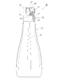
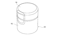
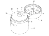
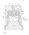
- the discharge container 10 includes a flexible inner container 11 that accommodates the contents M and is squeezed and deformed as the contents M decrease, and an inner container 11 that is internally housed and elastically deformed.
- a container main body 13 having a possible outer container 12 and a discharge cap 15 which is mounted on a mouth portion 13a of the container main body 13 and has a discharge port 14 for discharging the contents M is detachably disposed.
- the overcap 16 is provided.
- the container main body 13 is formed in a bottomed cylindrical shape
- the overcap 16 is formed in a topped cylindrical shape
- the container main body 13 and the overcap 16 are covered with the overcap 16 attached to the discharge cap 15.
- These center axes are arranged on a common axis (see FIG. 8 and the like).
- this common axis is referred to as the container axis O
- the overcap 16 side along the container axis O direction is referred to as the upper side
- the bottom side (not shown) of the container body 13 is referred to as the lower side
- the direction perpendicular to the container axis O is the diameter.
- the direction that goes around the container axis O is called the circumferential direction.
- the overcap 16 may be connected to the discharge cap 15 by the hinge part 16a (refer FIG. 2 etc.).
- the hinge portion 16 a is configured so that the discharge container 10 is inclined so that the discharge port 14 faces downward and the discharge port 10 is in a discharge posture. It is arranged to be higher than 14.
- the container body 13 is a so-called Delami bottle in which the inner container 11 is detachably laminated on the inner surface of the outer container 12.
- the container body 13 is formed by, for example, blow molding a co-extruded two-layer parison.
- the outer container 12 is made of, for example, polyethylene resin or polypropylene resin
- the inner container 11 is made of, for example, a polyamide-based synthetic resin that is not compatible with the resin forming the outer container 12 or ethylene vinyl alcohol. It is made of polymerized resin.
- the mouth portion 13a of the container body 13 is formed in a two-stage cylindrical shape including an upper cylindrical portion 17 positioned on the upper side and a lower cylindrical portion 18 positioned on the lower side and formed with a larger diameter than the upper cylindrical portion 17. (See FIG. 2 etc.).
- a male screw portion 29 is formed on the outer peripheral surface of a portion (hereinafter, referred to as an outer upper tube portion) 17 a formed of the outer container 12 in the upper tube portion 17.
- an intake hole 19 through which the outside air is sucked into the inner container 11 is formed in a portion of the outer upper cylinder portion 17a located below the male screw portion 29 (see FIG. 3 and the like).
- a communication groove 20 extending in the container axis O direction is formed in a portion of the male screw portion 29 located above the intake hole 19.
- An inner peripheral surface of the outer upper cylindrical portion 17a is a cylindrical surface, and a portion (hereinafter referred to as an inner upper cylindrical portion) 17b formed of the inner container 11 in the upper cylindrical portion 17 is laminated on the inner peripheral surface. (See FIG. 2 etc.).
- the upper end portion of the inner upper cylindrical portion 17b may be folded outwardly in the radial direction and disposed on the open end of the outer upper cylindrical portion 17a.
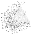
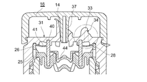
- the discharge cap 15 includes an inner plug member 21 that closes the mouth portion 13a of the container main body 13, and a top-like cylindrical main body cylinder member 23 that covers the inner plug member 21 and has the discharge port 14 formed therein. (See FIG. 2 etc.).
- the inner plug member 21 includes a plug main body 47 whose outer peripheral edge is disposed on the opening end of the mouth portion 13 a of the container main body 13, and a communication cylinder portion 22 erected from the plug main body 47.
- the stopper body 47 has a bottomed cylindrical inner cylinder portion 24 disposed in the mouth portion 13a of the container body 13 with a gap between the mouth portion 13a, and a radial direction from the upper end of the inner cylinder portion 24.
- a flange portion 25 that protrudes toward the outside of the container body 13 and is disposed on the open end of the mouth portion 13a of the container body 13, and an outer cylinder portion 26 that extends upward from the outer peripheral edge of the flange portion 25;
- An intermediate tube portion 27 extending downward from the flange portion 25 so as to surround the inner tube portion 24 from the outside in the radial direction and fitted in the mouth portion 13a of the container body 13 in a liquid-tight manner. (Refer to FIG. 2 etc.).
- the inner cylinder part 24, the flange part 25, the outer cylinder part 26 and the intermediate cylinder part 27 are arranged coaxially with the container axis O.
- An outer air circulation hole 28 that penetrates in the radial direction and opens downward is formed at the lower end portion of the outer cylinder portion 26.
- the communication tube portion 22 is disposed on the bottom wall portion of the inner tube portion 24.
- a through-hole 42 that opens both in the inner container 11 and in the communication cylinder portion 22 is provided in the bottom wall portion.
- the through hole 42 is constituted by a plurality of small holes that are evenly arranged around the container axis O, for example (see FIG. 2 and the like).
- the main body cylinder member 23 is formed in the shape of a top cylinder arranged coaxially with the container axis O.
- a female screw portion 30 is formed that is screwed to the male screw portion 29 of the mouth portion 13 a of the container main body 13.
- the lower cylinder portion 18 in the mouth portion 13a of the container body 13 is fitted in an airtight state in a lower end portion located below the screw portion where the female screw portion 30 is formed, and the screw
- the outer tube portion 26 of the inner plug member 21 is fitted in the upper end portion located above the portion.
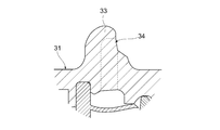
- a discharge port 14 for discharging the contents M is formed in the top surface portion 31 of the discharge cap 15 (see FIG. 5 and the like).
- the discharge port 14 is formed so as to be coaxial with the container axis O (see FIG. 2 and the like), but may be formed at a position shifted from the container axis O. .
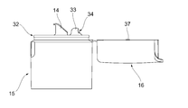
- the top surface portion 31 of the discharge cap 15 is formed with an outside air introduction projection 33 protruding upward, and an outside air introduction hole 34 is formed in the outside air introduction projection 33 (see FIG. 2 and the like).
- the outside air introduction protrusion 33 is in a state where the discharge container 10 is inclined to be in a discharge posture in order to discharge the contents M from the discharge port 14. And formed at a position higher than the discharge port 14 (see FIG. 2 and the like).
- the outside air introduction projection 33 is formed so as to stand between the discharge port 14 and the hinge portion 16 a, and the outside air introduction hole 34 is located at a position higher than the top surface portion 31. It is arranged at a spatial distance from 31. For this reason, even if the content M dripping from the discharge port 14 adheres to the outer surface of the discharge cap 15, the dripping content M is hardly sucked from the outside air introduction hole 34.
- the outside air introduction hole 34 is opened upward when the discharge container 10 is inclined to discharge the contents from the discharge port 14, more preferably vertically upward of the outside air introduction protrusion 33. (See FIG. 2 etc.).
- the specific shape of the external air introduction protrusion 33 described above is not particularly limited.
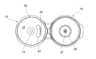
- the length in the circumferential direction is longer than the thickness of the discharge cap 15 in the radial direction (the direction perpendicular to the container axis O).
- it is formed in a curved shape along an arc centered on the discharge port 14 (see FIG. 5).
- the external air introduction protrusion 33 having such a shape the contents M adhering to the outer surface of the discharge cap 15 due to dripping or the like are prevented from approaching the external air introduction hole 34 and are sucked from the external air introduction hole 34. Can be avoided.
- the outside air introduction protrusion 33 is curved along an arc centered on the discharge port 14.
- the discharge cap 15 is formed with an engaging portion 32 with which the overcap 16 is engaged in the covered state.
- an engaging portion 32 with which the overcap 16 is engaged in the covered state.
- a step portion slightly projecting in the radial direction is formed around the top surface portion 31 of the discharge cap 15, and the over cap 16 in the covered state is engaged by the step portion.
- a joint portion 32 is formed (see FIGS. 2 and 5).
- the top surface portion 31 is formed smoothly.
- a portion of the top surface portion 31 excluding the portion where the discharge port 14 is formed and the portion where the outside air introduction protrusion 33 is formed is a smooth surface. In this case, wiping is easy, for example, even if the content M that has dripped in liquid adheres to the top surface portion 31 of the discharge cap 15, it can be wiped with one wipe.
- the top surface portion 31 is formed with a receiving tube portion 35 extending downward and having an outer diameter equal to an inner diameter of an outer fitting tube portion 40 described later. Further, a discharge cylinder 36 whose inside is the discharge port 14 is provided through the upper plate portion 32.
- an inner seal cylinder part (seal part) 37 extending downward from the overcap 16 is fitted (see FIGS. 1, 5, 8, etc.). Further, an annular protrusion 38 is formed around the inner seal cylinder portion 37 so as to protrude downward from the back surface of the overcap 16 (see FIG. 5 and the like).
- the overcap 16 is formed with an outside air introduction hole seal portion 39 that closes the outside air introduction hole 34 when the overcap 16 is attached to the discharge cap 15 (see FIGS. 8 and 9). If the overcap 16 is attached to the discharge cap 15 when the discharge container 10 is not used or transported, the outside air introduction hole seal portion 39 causes the contents M to be sucked in unexpectedly from the outside air introduction hole 34. Is avoided (see FIGS. 4 and 8).
- an outer fitting cylinder portion 40 that is externally fitted to the communication cylinder portion 22 of the inner plug member 21 is disposed.
- the outer fitting cylinder part 40 is arranged coaxially with the container axis O, and the lower end part of the outer fitting cylinder part 40 is fitted on the communication cylinder part 22 and in the inner cylinder part 24 of the inner plug member 21.
- the upper end part of the outer fitting cylinder part 40 is fitted on the receiving cylinder part 35 of the main body cylinder member 23.
- An annular air valve portion 41 projecting outward in the radial direction is formed at an intermediate portion of the outer fitting tube portion 40 in the container axis O direction (see FIGS. 2 and 3).
- the air valve portion 41 is elastically deformable, and switches between communication between the intake hole 19 and the outside air introduction hole 34 and blocking of the communication.
- the inner stopper member 21 is formed with a communication recess 43 that allows the discharge cylinder 36 and the inner container 11 to communicate with each other.
- the communication concave portion 43 is configured by the inside of the communication cylinder portion 22 and is disposed coaxially with the container axis O. Thereby, the container axis O direction and the axial direction of the communication recessed part 43 correspond.
- the communication recess 43 is located below the discharge cylinder 36, that is, inside the inner container 11 along the container axis O direction. Furthermore, the internal volume of the communication recess 43 is larger than the internal volume of the discharge cylinder 36.
- a valve body 44 that is slidably fitted along the container axis O direction and is slid along the container axis O direction to open and close the communication recess 43 inside the communicating cylinder portion 22 of the inner plug member 21. Is arranged.
- the valve body portion 44 is formed in a bottomed cylindrical shape disposed coaxially with the container axis O, and further has an annular flange portion projecting radially outward from an upper end (upper end) in the container axis O direction. It is regulated to have a shape.
- the annular upper end surface of the communication cylinder portion 22 functions as a valve seat (valve retainer) that receives the valve body portion 44 in contact with the flange portion.
- the outer peripheral surface of the valve body portion 44 and the inner peripheral surface of the communication recess 43 may be less likely to contact each other, or the bottom surface of the valve body portion 44 may be more radial than the communication cylinder portion 22 in the plug body 47. It is good also as a structure which does not contact
- valve body portion 44 is in contact with the upper end surface of the communicating cylinder portion 22 or is located above the upper end surface, and as shown in FIGS. Is connected to one end of a connecting piece 45 that connects the valve body portion 44 and the external fitting cylinder portion 40.
- a plurality of connection pieces 45 are provided at intervals in the circumferential direction, three in the illustrated example, and each connection piece 45 is curved and extends along the circumferential direction. Further, the positions of the both ends of the connecting piece 45 in the container axis O direction are the same.
- the valve body portion 44, the outer fitting cylinder portion 40, the connecting piece 45, and the air valve portion 41 are integrally formed to constitute a connecting body 48.
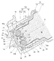
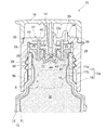
- the overcap 16 is removed from the discharge cap 15. After that, in a state where the discharge container 10 is tilted so as to face the lower side than the horizontal plane and in a discharge posture, the discharge container 10 is pressurized to be pushed inward in the radial direction to be squeezed (elastically deformed), The inner container 11 is deformed together with the outer container 12 to reduce the volume.
- the communication recess 43 is opened by being slid toward the outside of the inner container 11 along the axis O direction. As a result, the content M in the inner container 11 is discharged to the outside through the through hole 42, the communication recess 43, the outer fitting cylinder portion 40, and the discharge port 14 (see FIG. 2).
- valve body portion 44 slides inside the inner container 11 along the container axis O direction (see FIG. 3).
- the inner container 11 follows the outer container 12. Then try to restore and transform. Then, the pressure in the inner container 11 is reduced and a negative pressure is generated, and this negative pressure acts on the valve body part 44, so that the valve body part 44 is placed inside the inner container 11 along the container axis O direction. It will be made to slide smoothly toward.
- the discharge container 10 As described above, according to the discharge container 10 according to the present embodiment, after the content M is discharged, the content M in the discharge port 14 is drawn into the inner space 46 and air is discharged into the discharge port 14 from the outside. Since A can be sucked, it is possible to suppress the contents M that have not been returned to the inner container 11 from remaining in the discharge port 14. Thereby, after discharge of the content M, it can suppress that the content M leaks from the discharge outlet 14. FIG.
- the through hole 42 has a smaller diameter than the communication recess 43, even if the valve body portion 44 unintentionally displaces to the inside of the inner container 11 along the axial direction, the flange portion of the valve body portion 44. However, the stopper main body 47 comes into contact with the annular upper end surface of the communication cylinder portion 22, and the displacement of the valve body portion 44 can be restricted.
- valve body portion 44 when the valve body portion 44 is in contact with the stopper body 47 when the discharge container 10 is not operated, the valve body portion 44 allows the communication recess 43 and the through hole 42 to communicate with each other. Can be blocked. Furthermore, in this case, when the valve body 44 is restored and displaced after the contents M are discharged and the inner space 46 is formed as described above, the valve body 44 is placed in the communication recess 43 in the container. It can slide over the entire length in the direction of the axis O. As a result, the internal volume of the inner space 46 can be reliably increased, and the above-described effects can be remarkably achieved.
- the inner seal cylinder part 37 is provided in the overcap 16, it is possible to prevent the contents M from being unexpectedly leaked from the discharge port 14 with the overcap 16 closed. Further, as described above, after the contents M are discharged, the contents M that have not been returned to the inner container 11 are less likely to remain in the discharge port 14, so that the overcap 16 is discharged after the contents M are discharged. 15, when the inner seal cylinder portion 37 is fitted into the discharge port 14, the content M is pushed out of the discharge port 14 by the inner seal cylinder portion 37, or the content is stored in the inner seal cylinder portion 37. It can suppress that the thing M adheres.
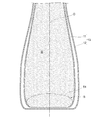
- FIG. 10 Another embodiment of the present invention is shown in FIG.
- gas is previously accommodated in the inner container 11 to form a gas space S (see FIGS. 10 and 11). Since the gas in the gas space S is more easily compressed than the content M, when the user presses the discharge container 10 in an attempt to use up the content M particularly when the content M is reduced (squeezed deformed). The contents M are discharged more effectively.
- the gas space S Since gas has a lighter specific gravity than the contents M, the gas space S exists as a head space vertically above the contents M in the normal state where the discharge container 10 is placed so that the discharge cap 15 faces upward. (See FIG. 11 and the like).
- the gas space S moves in the inner container 11 toward the bottom of the discharge container 10.
- the discharge container 10 As the content M decreases, the ratio of the gas space S to the remaining amount of the content M increases, so that the content M is pushed out by the gas space S compressed during pressurization (discharge) Action). Therefore, particularly when the content M is reduced, the pressurized and compressed gas space S acts to push and discharge the content M more effectively. Finally, the gas in the gas space S remains in the inner container 11 as a substitute for the contents M. Therefore, according to the discharge container 10 of the present invention, it is easy to discharge all of the contents M, and the residual amount can be reduced as compared with the conventional case.
- the gas is preferably one that quickly moves in the inner container 11 when the discharge container 10 is tilted to the discharge posture in order to discharge the contents M from the discharge port 14.
- the moving speed of the gas in this case can vary depending on the volume of the gas, the shape of the inner container 11, etc., but is largely influenced by the viscosity of the contents M. From the viewpoint of facilitating discharge of all the contents M and reducing the residual amount, the viscosity of the contents M is preferably within a range in which the gas can move quickly (Example). 2).
- the specific example of the content M is not specifically limited, Various things, such as an emulsified liquid, a modified starch mixture, a liquid food, a soy sauce containing seasoning (it is an example of a clear seasoning and contains soy sauce itself), are employ
- the specific example of gas is not specifically limited, It is preferable that it is a thing with low reactivity, such as oxidizing the contents M, such as nitrogen gas.
- the gas space S can be formed in a different form from the above.
- the gas space S can be formed by accommodating the gas bag 50 filled with gas in the inner container 11 (see FIG. 12). In such a discharge container 10, the gas space S is maintained in the inner container 11 until all the contents M are discharged.
- the material and shape of the gas bag 50 are preferably such that the gas bag 50 can move quickly in the inner container 11 when the discharge container 10 is tilted.
- the gas space 51 can be formed by forming the gas chamber 51 at the bottom of the inner container 11 and enclosing the gas in the gas chamber 51 (see FIG. 12).
- the gas chamber 51 can be formed by partitioning the inside of the inner container 11 with a flexible film, for example. Even in such a discharge container 10, the gas space S is maintained in the inner container 11 until all the contents M are discharged.
- the present inventor conducted a test as to what percentage or more of the gas space S is suitable for the capacity of the inner container 11 of the discharge container (delamination container) 10.
- ⁇ Test method> The masses of two types of 200 ml and 250 ml discharge containers 10 were measured, the contents of the gas space S were changed, the contents (liquid) were filled, and all were discharged. The tablespoons (15 ml) were discharged in 14 to 17 times. When the contents M could not be discharged, the mass was measured and the remaining liquid amount was calculated. Therefore, the residual liquid in the discharge container 10 and the residual liquid in the discharge cap 15 are combined and appear in the result.
- the present inventor has verified the difference in the viscosity of the content M in order to confirm how much the effect of reducing the residual amount by making it easy to discharge all of the content M is different.
- ponzu jelly was used as the high-viscosity liquid food.
- the liquid foods that can be discharged are all those having a lower viscosity than the ponzu jelly.
- the present invention is suitable for application to a discharge container having a laminate peeling structure containing an emulsified liquid, a modified starch mixture, a liquid food, and the like as contents.
Abstract
Description
200ml、250mlの2種類の吐出容器10の質量を測定し、気体スペースSの容量を変えて内容物(液)を充填し、全て排出した。大さじ(15ml)ずつ、14~17回に分けて排出を行った。内容物Mを排出できなくなった時点で質量測定し、残液量を算出した。したがって、吐出容器10内の残液と、吐出キャップ15内の残液も合わせて結果に出てくることとなった。 <Test method>
The masses of two types of 200 ml and 250
試験結果を図14に示す。この試験結果からは、気体スペースSを形成する気体の容量が内容器11の容量の4%以上(S/(M+S)が4%以上)である場合に、内容物Mの残液量を極めて少なくすることが可能であることが分かった。 <Result>
The test results are shown in FIG. From this test result, when the volume of the gas forming the gas space S is 4% or more of the capacity of the inner container 11 (S / (M + S) is 4% or more), the residual liquid amount of the contents M is extremely low. It turns out that it can be reduced.
ポン酢ジュレを吐出容器に充填し、実施例1の試験方法と同様に排出を行った。 <Test method>
The ponzu jelly was filled in a discharge container and discharged in the same manner as in the test method of Example 1.
気体スペースSが4%以上で同様に内容物Mの残液量を少なくすることができた。 <Result>
When the gas space S was 4% or more, the remaining liquid amount of the contents M could be reduced similarly.
ポン酢ジュレ
・B型粘度計 25℃ローターNo.3―12回転 で測定
3500cp
・B型粘度計 25℃ローターNo.3―30回転 で測定
1840cp <Viscosity measurement result>
Ponzu jelly ・ B-type viscometer Measured at 25 ℃ Rotor No.3-12 rotation 3500cp
・ B type viscometer Measured at 25 ℃ Rotor No.3-30 rotation 1840cp
25℃、No.1spindle使用、回転数60rpm
使用機器:ブルックデジタル粘度計LVDVー1
粘度 Brix
・しょうゆA: 0.91cP 37.42%
・しょうゆB: 0.73cP 32.21%
・しょうゆC: 1.05cP 39.37% soy sauce
25 ℃, No.1 spindle use, rotation speed 60rpm
Equipment used: Brook Digital Viscometer LVDV-1
Viscosity Brix
・ Soy sauce A: 0.91cP 37.42%
・ Soy sauce B: 0.73cP 32.21%
・ Soy sauce C: 1.05cP 39.37%
11…内容器
12…外容器
13…容器本体
13a…口部
14…吐出口
15…吐出キャップ
19…吸気孔
31…天面部
34…外気導入孔
41…空気弁部
50…気体袋
51…気体室
M…内容物
S…気体スペース DESCRIPTION OF
Claims (7)
- 内容物が収容されるとともに内容物の減少に伴いしぼみ変形する可撓性の内容器、および該内容器が内装されており、弾性変形して該内容器との間に外気を吸入するための吸気孔が形成された外容器を有する容器本体と、
内容物を吐出する吐出口が天面部に形成されており、該容器本体の口部に装着される吐出キャップと、
外部と前記吸気孔とを連通する外気導入孔と、
該外気導入孔と前記吸気孔との連通およびその遮断を切り替える空気弁部と、を備える吐出容器であって、
前記内容器内に気体が収容されて気体スペースが形成されており、
前記気体の容量が前記内容器の容量の4%以上である、吐出容器。 A flexible inner container that accommodates the contents and deforms in accordance with a decrease in the contents, and the inner container is provided, and is elastically deformed to suck outside air between the inner container and the inner container. A container body having an outer container in which an intake hole is formed;
A discharge port for discharging contents is formed on the top surface, and a discharge cap attached to the mouth of the container body,
An outside air introduction hole communicating the outside and the intake hole;
A discharge valve comprising: an air valve portion for switching communication between the outside air introduction hole and the intake hole and blocking the air hole;
A gas space is formed by containing gas in the inner container,
The discharge container, wherein the volume of the gas is 4% or more of the volume of the inner container. - 前記気体は、前記吐出口から内容物を吐出させるために当該吐出容器を傾けて吐出姿勢にした際、前記内容器内を速やかに移動するものである、請求項1に記載の吐出容器。 2. The discharge container according to claim 1, wherein the gas rapidly moves in the inner container when the discharge container is tilted to a discharge posture in order to discharge contents from the discharge port.
- 前記気体が気体袋に封入されている、請求項1または2に記載の吐出容器。 The discharge container according to claim 1 or 2, wherein the gas is sealed in a gas bag.
- 前記内容器内に形成された気体室に前記気体が封入されている、請求項1に記載の吐出容器。 The discharge container according to claim 1, wherein the gas is sealed in a gas chamber formed in the inner container.
- 前記気体室が前記内容器の底部に形成されている、請求項4に記載の吐出容器。 The discharge container according to claim 4, wherein the gas chamber is formed at the bottom of the inner container.
- 前記内容物が液状食品である、請求項1から5のいずれか一項に記載の吐出容器。 The discharge container according to any one of claims 1 to 5, wherein the content is a liquid food.
- 前記内容物が醤油含有調味料である、請求項1から6のいずれか一項に記載の吐出容器。 The discharge container according to any one of claims 1 to 6, wherein the content is a soy sauce-containing seasoning.
Priority Applications (5)
| Application Number | Priority Date | Filing Date | Title |
|---|---|---|---|
| US14/236,699 US9315313B2 (en) | 2011-08-05 | 2012-07-20 | Dispensing container |
| EP12822229.6A EP2740688B1 (en) | 2011-08-05 | 2012-07-20 | Dispensing container |
| KR1020147005492A KR20140043162A (en) | 2011-08-05 | 2012-07-20 | Dispensing container |
| CN201280038740.3A CN103764516B (en) | 2011-08-05 | 2012-07-20 | Spue container |
| ES12822229.6T ES2609353T3 (en) | 2011-08-05 | 2012-07-20 | Dispensing container |
Applications Claiming Priority (2)
| Application Number | Priority Date | Filing Date | Title |
|---|---|---|---|
| JP2011-171850 | 2011-08-05 | ||
| JP2011171850A JP6336702B2 (en) | 2011-08-05 | 2011-08-05 | Discharge container |
Publications (1)
| Publication Number | Publication Date |
|---|---|
| WO2013021802A1 true WO2013021802A1 (en) | 2013-02-14 |
Family
ID=47668318
Family Applications (1)
| Application Number | Title | Priority Date | Filing Date |
|---|---|---|---|
| PCT/JP2012/068481 WO2013021802A1 (en) | 2011-08-05 | 2012-07-20 | Dispensing container |
Country Status (8)
| Country | Link |
|---|---|
| US (1) | US9315313B2 (en) |
| EP (1) | EP2740688B1 (en) |
| JP (1) | JP6336702B2 (en) |
| KR (1) | KR20140043162A (en) |
| CN (1) | CN103764516B (en) |
| ES (1) | ES2609353T3 (en) |
| TW (1) | TWI552927B (en) |
| WO (1) | WO2013021802A1 (en) |
Cited By (4)
| Publication number | Priority date | Publication date | Assignee | Title |
|---|---|---|---|---|
| EP2832658A1 (en) * | 2013-07-30 | 2015-02-04 | ainia | Dispensing container and method of filling the container |
| AU2015265081B2 (en) * | 2014-05-27 | 2018-11-08 | Toyo Seikan Group Holdings, Ltd. | Method of Filling Liquid Content and Packing Container Filled with Liquid Content |
| CN114430726A (en) * | 2019-09-01 | 2022-05-03 | 罗恩·里蒙 | Dispensing container and bag device |
| JP7422356B2 (en) | 2020-01-31 | 2024-01-26 | 東京ライト工業株式会社 | cap |
Families Citing this family (24)
| Publication number | Priority date | Publication date | Assignee | Title |
|---|---|---|---|---|
| WO2015046024A1 (en) * | 2013-09-27 | 2015-04-02 | キョーラク株式会社 | Layer separating container |
| WO2015080015A1 (en) | 2013-11-27 | 2015-06-04 | キョーラク株式会社 | Delamination container, pinhole checking method therefor, and processing method therefor |
| ES2674380T3 (en) | 2013-11-27 | 2018-06-29 | Kyoraku Co., Ltd. | Delaminable container |
| JP6177704B2 (en) * | 2014-02-10 | 2017-08-09 | 株式会社吉野工業所 | Squeeze dispensing tap |
| TWI642600B (en) * | 2014-02-12 | 2018-12-01 | 日商京洛股份有限公司 | Delamination container, pinhole checking method therefor, and processing method therefor |
| CN109229696B (en) | 2014-10-07 | 2020-05-15 | 京洛株式会社 | Method for manufacturing laminated and peeled container, and method for inspecting gas leakage of laminated and peeled container |
| JP6761159B2 (en) | 2014-11-19 | 2020-09-23 | キョーラク株式会社 | Laminate peeling container |
| KR101969919B1 (en) | 2015-01-23 | 2019-04-17 | 교라꾸 가부시끼가이샤 | Lamination peeling container |
| JP6489851B2 (en) | 2015-01-30 | 2019-03-27 | 株式会社吉野工業所 | Double container |
| JP6537319B2 (en) * | 2015-03-30 | 2019-07-03 | 東京ライト工業株式会社 | cap |
| USD798712S1 (en) * | 2015-04-01 | 2017-10-03 | Kikkoman Corporation | Container lid |
| JP2016216124A (en) * | 2015-05-26 | 2016-12-22 | 株式会社吉野工業所 | Discharge container |
| EP3305673B1 (en) | 2015-05-28 | 2019-09-25 | Kyoraku Co., Ltd. | Double container |
| KR101609993B1 (en) * | 2015-10-27 | 2016-04-06 | 이병희 | Food container discharge device |
| CN108367830B (en) | 2015-12-03 | 2022-12-23 | 京洛株式会社 | Laminated peeling container |
| JP6973987B2 (en) | 2016-02-04 | 2021-12-01 | 小橋工業株式会社 | How to use the farm work machine |
| CN114834719A (en) | 2016-04-15 | 2022-08-02 | 京洛株式会社 | Laminated peeling container |
| JP6820169B2 (en) | 2016-08-31 | 2021-01-27 | 株式会社吉野工業所 | Discharge container |
| JP6914634B2 (en) * | 2016-10-14 | 2021-08-04 | 東洋製罐グループホールディングス株式会社 | Preform for stack type double structure container molding |
| KR20200006042A (en) * | 2017-04-05 | 2020-01-17 | 기꼬만 가부시키가이샤 | Discharge vessel |
| JP7219704B2 (en) * | 2017-04-05 | 2023-02-08 | キッコーマン株式会社 | Double-packaged food and beverage composition |
| DE102017121702B4 (en) | 2017-09-19 | 2019-07-11 | Inotech Kunststofftechnik Gmbh | Dispenser container and device for producing the dispenser container |
| JP2019206360A (en) * | 2018-05-29 | 2019-12-05 | 凸版印刷株式会社 | Packaging container |
| JP7427335B2 (en) * | 2020-03-26 | 2024-02-05 | 株式会社吉野工業所 | container with liquid |
Citations (8)
| Publication number | Priority date | Publication date | Assignee | Title |
|---|---|---|---|---|
| JPS51125581A (en) * | 1975-04-03 | 1976-11-02 | Wright Hershel Earl | Foam delivery device |
| JPS6243660U (en) * | 1985-08-30 | 1987-03-16 | ||
| JPH047443U (en) * | 1990-04-28 | 1992-01-23 | ||
| JP3688373B2 (en) | 1995-12-22 | 2005-08-24 | 株式会社吉野工業所 | Laminated peeling container that can be extruded |
| JP4024396B2 (en) | 1998-07-31 | 2007-12-19 | 花王株式会社 | Comb application tool |
| JP2008162666A (en) * | 2006-12-28 | 2008-07-17 | Yoshino Kogyosho Co Ltd | Discharging container |
| JP2009149322A (en) * | 2007-12-19 | 2009-07-09 | Kao Corp | Squeeze bottle |
| JP2009149327A (en) * | 2007-12-19 | 2009-07-09 | Kao Corp | Delamination container |
Family Cites Families (20)
| Publication number | Priority date | Publication date | Assignee | Title |
|---|---|---|---|---|
| FR1314002A (en) * | 1961-11-24 | 1963-01-04 | Method and device for dispensing a non-compacted substance | |
| US3937364A (en) | 1975-04-03 | 1976-02-10 | Hershel Earl Wright | Foam dispensing device |
| JP2569369B2 (en) | 1989-06-23 | 1997-01-08 | キッコーマン株式会社 | How to make soy sauce |
| JPH0614078U (en) * | 1991-08-05 | 1994-02-22 | 良康 住吉 | Double structure container |
| DE4332885A1 (en) * | 1992-09-28 | 1994-03-31 | Colgate Palmolive Co | Squeezable dispenser for toothpaste etc. - has inner flexible disposable container fitting into outer container and closed by cap and one-way locking valves |
| JPH08164954A (en) * | 1994-12-15 | 1996-06-25 | Yoshida Kogyo Kk <Ykk> | Tube container |
| JPH09278024A (en) * | 1996-04-10 | 1997-10-28 | Mitsubishi Gas Chem Co Inc | Filling method for liquid or semi-liquid substance |
| JP2001106263A (en) * | 1999-08-02 | 2001-04-17 | Kao Corp | Double container |
| JP4580524B2 (en) * | 2000-09-12 | 2010-11-17 | 株式会社日本点眼薬研究所 | Discharge container with filter |
| JP4749572B2 (en) * | 2001-03-13 | 2011-08-17 | 大成化工株式会社 | Dispensing container plug structure |
| WO2002090211A1 (en) * | 2001-05-07 | 2002-11-14 | Wella Aktiengesellschaft | Container arrangement for removing and applying partial amounts of a liquid product |
| JP2003063576A (en) * | 2001-06-15 | 2003-03-05 | Taisei Kako Co Ltd | Dispensing vessel |
| DE60237979D1 (en) * | 2001-08-31 | 2010-11-25 | Yoshino Kogyosho Co Ltd | AUSGUSSBEHÄLTER |
| JP2005350090A (en) * | 2004-06-09 | 2005-12-22 | Mitsukan Group Honsha:Kk | Method for filling liquid food in thermoplastic resin-made container |
| US20090308888A1 (en) | 2004-11-15 | 2009-12-17 | Teikokumedix Co., Ltd | Package filled with gel or paste content and gas |
| CN101084154A (en) * | 2004-12-16 | 2007-12-05 | 帝客明株式会社 | Package filled with gel or paste content and gas |
| JP5295901B2 (en) * | 2009-07-31 | 2013-09-18 | 株式会社吉野工業所 | Double container pouring cap and double container with pouring cap |
| JP5579421B2 (en) * | 2009-11-30 | 2014-08-27 | 株式会社吉野工業所 | Hinge cap with tamper-evident mechanism |
| US8464908B1 (en) * | 2011-02-17 | 2013-06-18 | Norman W. Tabor | Multi-directional fluid dispenser |
| US8430107B2 (en) * | 2011-03-11 | 2013-04-30 | Yu Chang Esthetics Consultant Co., Ltd. | Foam output device easy to produce foam |
-
2011
- 2011-08-05 JP JP2011171850A patent/JP6336702B2/en active Active
-
2012
- 2012-07-20 KR KR1020147005492A patent/KR20140043162A/en active Search and Examination
- 2012-07-20 WO PCT/JP2012/068481 patent/WO2013021802A1/en active Application Filing
- 2012-07-20 EP EP12822229.6A patent/EP2740688B1/en active Active
- 2012-07-20 US US14/236,699 patent/US9315313B2/en active Active
- 2012-07-20 ES ES12822229.6T patent/ES2609353T3/en active Active
- 2012-07-20 CN CN201280038740.3A patent/CN103764516B/en active Active
- 2012-08-03 TW TW101128122A patent/TWI552927B/en active
Patent Citations (8)
| Publication number | Priority date | Publication date | Assignee | Title |
|---|---|---|---|---|
| JPS51125581A (en) * | 1975-04-03 | 1976-11-02 | Wright Hershel Earl | Foam delivery device |
| JPS6243660U (en) * | 1985-08-30 | 1987-03-16 | ||
| JPH047443U (en) * | 1990-04-28 | 1992-01-23 | ||
| JP3688373B2 (en) | 1995-12-22 | 2005-08-24 | 株式会社吉野工業所 | Laminated peeling container that can be extruded |
| JP4024396B2 (en) | 1998-07-31 | 2007-12-19 | 花王株式会社 | Comb application tool |
| JP2008162666A (en) * | 2006-12-28 | 2008-07-17 | Yoshino Kogyosho Co Ltd | Discharging container |
| JP2009149322A (en) * | 2007-12-19 | 2009-07-09 | Kao Corp | Squeeze bottle |
| JP2009149327A (en) * | 2007-12-19 | 2009-07-09 | Kao Corp | Delamination container |
Non-Patent Citations (1)
| Title |
|---|
| See also references of EP2740688A4 * |
Cited By (7)
| Publication number | Priority date | Publication date | Assignee | Title |
|---|---|---|---|---|
| EP2832658A1 (en) * | 2013-07-30 | 2015-02-04 | ainia | Dispensing container and method of filling the container |
| WO2015014828A1 (en) * | 2013-07-30 | 2015-02-05 | Ainia | Dispensing container and method of filling the container |
| ES2612525R1 (en) * | 2013-07-30 | 2017-07-25 | Ainia | DISPENSER PACKAGING AND CONTAINER FILLING METHOD |
| AU2015265081B2 (en) * | 2014-05-27 | 2018-11-08 | Toyo Seikan Group Holdings, Ltd. | Method of Filling Liquid Content and Packing Container Filled with Liquid Content |
| AU2018274965B2 (en) * | 2014-05-27 | 2020-06-11 | Toyo Seikan Group Holdings, Ltd. | Method of filling liquid content and packing container filled with liquid content |
| CN114430726A (en) * | 2019-09-01 | 2022-05-03 | 罗恩·里蒙 | Dispensing container and bag device |
| JP7422356B2 (en) | 2020-01-31 | 2024-01-26 | 東京ライト工業株式会社 | cap |
Also Published As
| Publication number | Publication date |
|---|---|
| ES2609353T3 (en) | 2017-04-19 |
| JP2013035557A (en) | 2013-02-21 |
| TW201313561A (en) | 2013-04-01 |
| TWI552927B (en) | 2016-10-11 |
| CN103764516B (en) | 2015-10-14 |
| EP2740688B1 (en) | 2016-10-12 |
| EP2740688A4 (en) | 2015-04-08 |
| US9315313B2 (en) | 2016-04-19 |
| JP6336702B2 (en) | 2018-06-06 |
| KR20140043162A (en) | 2014-04-08 |
| US20140190992A1 (en) | 2014-07-10 |
| CN103764516A (en) | 2014-04-30 |
| EP2740688A1 (en) | 2014-06-11 |
Similar Documents
| Publication | Publication Date | Title |
|---|---|---|
| JP6336702B2 (en) | Discharge container | |
| JP5295460B2 (en) | Discharge container | |
| JP6283431B2 (en) | Discharge container | |
| US9132955B2 (en) | Compressible valve for a pressurized container | |
| US10174884B2 (en) | Valve stem for a compressible valve | |
| WO2012169489A1 (en) | Dispensing container | |
| US10781017B2 (en) | Cap and discharge container | |
| US9758295B2 (en) | Compressible valve for a pressurized container | |
| US20160377186A1 (en) | Compressible valve and actuator for a pressurized container | |
| JP2016216124A (en) | Discharge container | |
| JP6475542B2 (en) | Discharge container and its discharge cap and overcap | |
| JP6359405B2 (en) | Double container | |
| JP6523745B2 (en) | Discharge container and its discharge cap and overcap |
Legal Events
| Date | Code | Title | Description |
|---|---|---|---|
| 121 | Ep: the epo has been informed by wipo that ep was designated in this application |
Ref document number: 12822229 Country of ref document: EP Kind code of ref document: A1 |
|
| REEP | Request for entry into the european phase |
Ref document number: 2012822229 Country of ref document: EP |
|
| WWE | Wipo information: entry into national phase |
Ref document number: 2012822229 Country of ref document: EP |
|
| NENP | Non-entry into the national phase |
Ref country code: DE |
|
| ENP | Entry into the national phase |
Ref document number: 20147005492 Country of ref document: KR Kind code of ref document: A |
|
| WWE | Wipo information: entry into national phase |
Ref document number: 14236699 Country of ref document: US |