WO2013015295A1 - Vertical takeoff and landing aircraft - Google Patents
Vertical takeoff and landing aircraft Download PDFInfo
- Publication number
- WO2013015295A1 WO2013015295A1 PCT/JP2012/068768 JP2012068768W WO2013015295A1 WO 2013015295 A1 WO2013015295 A1 WO 2013015295A1 JP 2012068768 W JP2012068768 W JP 2012068768W WO 2013015295 A1 WO2013015295 A1 WO 2013015295A1
- Authority
- WO
- WIPO (PCT)
- Prior art keywords
- rotor
- center
- main wing
- rotor shaft
- gravity
- Prior art date
Links
Images


Classifications
-
- B—PERFORMING OPERATIONS; TRANSPORTING
- B64—AIRCRAFT; AVIATION; COSMONAUTICS
- B64C—AEROPLANES; HELICOPTERS
- B64C29/00—Aircraft capable of landing or taking-off vertically, e.g. vertical take-off and landing [VTOL] aircraft
- B64C29/0008—Aircraft capable of landing or taking-off vertically, e.g. vertical take-off and landing [VTOL] aircraft having its flight directional axis horizontal when grounded
- B64C29/0016—Aircraft capable of landing or taking-off vertically, e.g. vertical take-off and landing [VTOL] aircraft having its flight directional axis horizontal when grounded the lift during taking-off being created by free or ducted propellers or by blowers
- B64C29/0033—Aircraft capable of landing or taking-off vertically, e.g. vertical take-off and landing [VTOL] aircraft having its flight directional axis horizontal when grounded the lift during taking-off being created by free or ducted propellers or by blowers the propellers being tiltable relative to the fuselage
Definitions
- the present invention relates to a vertical take-off and landing aircraft that takes off and land vertically by turning the rotor's rotating surface downward and moves forward by turning the rotor's rotating surface backward.
- a rotor shaft that is rotationally driven by a drive source is provided on the main wing so that it can rotate between a vertical posture with the tip facing the lower side of the main wing and a horizontal posture with the tip facing the rear of the main wing.
- a rotor is attached to the tip of the slab (see claim 1 of Patent Document 1).
- This vertical take-off and landing aircraft takes the rotor shaft into a vertical position with the tip facing the lower side of the main wing, and takes the rotor shaft into the vertical position with the rotating surface of the rotor facing the lower side of the main wing. The rotating surface is advanced toward the rear of the main wing.
- the rotor shaft When taking off and landing vertically, the rotor shaft is in a vertical posture, and it is desirable that the rotor shaft be arranged at the center of gravity of the aircraft. If the rotor shaft deviates forward or backward from the center of gravity of the aircraft, the pitching moment is applied to the aircraft during vertical ascent and descent due to the deviation between the lift acting position (rotor shaft position) and the aircraft weight acting position (center of gravity position). This is because it will occur.
- the aircraft will roll backward due to the lift of the rotor when vertically rising, and if the rotor shaft is shifted backward from the center of gravity of the aircraft, The aircraft rolls forward due to the lift of the rotor.
- the position of the center of gravity of the fuselage is usually set to a position about 25% to 30% behind the chord from the leading edge of the main wing. For this reason, if the rotor shaft is arranged in a vertical position at the center of gravity, the rotor shaft can be rotated backward about the center of gravity of the fuselage so that the rotor rotation surface is behind the trailing edge of the main wing. , The length of the rotor shaft (the length from the center of gravity of the fuselage to the rotor mounting part at the tip of the rotor shaft) than the distance from the center of gravity of the fuselage to the trailing edge of the main wing (about 70% to 75% of the chord) It must be long.
- the present inventor attempted to shorten the rotor shaft by folding the rotor power transmission mechanism, and when the rotor shaft was in a vertical posture during vertical takeoff and landing, the lower surface of the main wing and the rotating surface of the rotor Proposed a vertical take-off and landing aircraft that shortens the distance (see claim 2 of Patent Document 1).
- This vertical take-off and landing aircraft is provided with a case that supports the rotor shaft on the main wing so that it can be moved back and forth, and can be rotated.
- the case where the rotor shaft is supported in a vertical position is moved forward to move the rotor shaft to a vertical position.
- the center of gravity of the fuselage is placed, and the case is moved rearward from that state and rotated rearward so that the rotor shaft is in a horizontal posture and the rotor rotation surface is located behind the trailing edge of the main wing.
- the length of the rotor shaft can be shortened compared to the case where the rotor shaft is simply rotated backward about the center of gravity of the fuselage, and the rotor shaft is positioned vertically and the rotor rotation surface is below the main wing. , The distance between the lower surface of the main wing and the rotating surface of the rotor can be shortened.
- the purpose of the present invention which was created in view of the above circumstances, is a vertical take-off and landing aircraft that takes off and land vertically with the rotor's rotating surface facing the lower side of the main wing, and advances the rotor's rotating surface toward the rear of the main wing.
- An object of the present invention is to provide a vertical take-off and landing aircraft that can reduce the length of the rotor shaft with a light and simple structure.
- the vertical take-off and landing aircraft which was created to achieve the above-mentioned object, sets the center of gravity position of the fuselage in an area on the trailing edge side from the center of the chord of the main wing when the aircraft is viewed from the side.
- a rotor shaft that extends downward from the position of the center of gravity, has a rotor attached to the tip, and is driven to rotate to generate lift in the rotor, and the rotor shaft, with the tip located below the main wing with the center of gravity at the center.
- the length of the rotor shaft from the position of the center of gravity to the rotor mounting portion at the tip of the rotor shaft is set according to the length from the position of the center of gravity to the trailing edge of the main wing. Also good.
- the rotation means includes a rotation support mechanism that supports the rotor shaft so that the rotor shaft can rotate freely between the first posture and the second posture around the center of gravity.
- a pitch change mechanism that changes the rotor's cyclic pitch so that the rotation angle of the rotor shaft that is rotatably supported by the main wing is changed by the dynamic support mechanism, and a change in the rotor's cyclic pitch by the pitch change mechanism
- a lock mechanism for fixing a rotation angle of the rotor shaft rotated by the rotation of the rotor shaft.
- the pitch changing mechanism has a function of changing the cyclic pitch of the rotor so that the lift of the rear half side is higher than the lift of the front half side of the rotor when the rotor shaft is in the first posture. And having a function of changing the cyclic pitch of the rotor so that the lift on the lower half side is higher than the lift on the upper half side of the rotor when the rotor shaft is in the second posture.
- the aerodynamic center may be set on the main wing on the front edge side of the center of gravity position, and the horizontal tail arranged behind the main wing may generate lift.
- the main wing is located between the center of the chord and the trailing edge rather than the camber between the leading edge and the center of the chord so that the aerodynamic center is located on the trailing edge side of the center of gravity.
- An airfoil with a large camber in between may be used.
- the position of the center of gravity of the fuselage is set in the area on the trailing edge side of the center of the main wing chord, the rotor shaft is extended downward from the position of the center of gravity, and the rotor shaft is rotated by rotating means. It is made to rotate between the 1st attitude
- the rotor shaft extends downward from the center of gravity of the fuselage, which is set in the trailing edge side area of the main wing chord center, when the rotor shaft is rotated backward to the second position,
- the length of the rotor shaft required to make the rotating surface behind the trailing edge of the main wing, the center of gravity position of the fuselage is in the area on the leading edge side of the main wing (25% to 30% behind the chord from the leading edge) It can be shorter than the normal setting.
- This effect is achieved by setting the center of gravity position of the fuselage in the area on the trailing edge side of the center of the main wing chord and extending the rotor shaft downward from the center of gravity position.
- the length of the rotor shaft can be shortened with a light and simple structure.
- the rotor shaft can be shortened, when the rotor is oriented downward from the main wing with the rotor shaft in the first posture, the distance between the rotor's rotating surface and the ground can be secured, and the center of gravity of the fuselage is lowered. It becomes possible to do. Therefore, the stability during vertical ascent (descent) is improved.
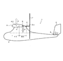
- FIG. 1 It is the perspective view which looked at the vertical take-off and landing aircraft concerning one embodiment of the present invention from the slanting back. It is the side view of the main wing, rotor shaft, and rotor which looked at the above-mentioned vertical take-off and landing machine from the left wing end direction, (a) is a side view which made the rotor shaft the 1st posture with the tip facing down, and (b) It is a side view made into the 2nd attitude
- FIG. 2 is a partial plan sectional view of the vertical take-off and landing aircraft (rotor shaft in a second posture).
- A) is the elements on larger scale of FIG. 5
- (b) is the fragmentary sectional side view of (a). It is explanatory drawing when rotating the rotor shaft of the said vertical take-off and landing aircraft from the 1st attitude
- the vertical take-off and landing aircraft 1 is an area on the trailing edge side from the center of the chord of the main wing 3 when the aircraft is viewed from the side.
- the center of gravity position of the fuselage is set, the rotor shaft 2 is extended from the main wing 3 downward to the center of gravity position, and the rotor shaft 2 is centered on the center of gravity position and the tip 2a faces the lower side of the main wing 3 (hereinafter referred to as the first posture).
- the vertical posture includes a substantially vertical posture that is not completely vertical but slightly inclined (for example, a range of 5 degrees or less), and the horizontal posture includes a substantially horizontal posture that is not completely horizontal but is also slightly inclined. .
- the vertical take-off and landing aircraft 1 includes a fuselage 4, a main wing 3 attached to the fuselage 4, a horizontal tail 5 attached to the rear of the fuselage 4 behind the main wing 3, and a vertical tail attached to the rear of the fuselage 4. 6 is provided.
- Each of the left and right main wings 3 is provided with one rotor shaft 2 described above, and a rotor 7 is attached to the tip 2 a of each rotor shaft 2.
- the left and right rotor shafts 2 are rotated between a vertical posture and a horizontal posture around the position of the center of gravity by rotation means described later.
- a drive source (engine, motor, etc.) 8 for rotating the left and right rotor shafts 2 is provided inside the fuselage 4, and the rotational force of the drive source 8 is applied to each rotor shaft inside the fuselage 4 and the main wing 3.
- a power transmission mechanism 9 is provided which transmits the left and right rotor shafts 2 in reverse directions.
- the power transmission mechanism 9 includes a gear box 10 housed inside a base portion of the main wing 3 (attachment portion to the fuselage 4), and a first drive shaft 11 provided between the drive source 8 and the gear box 10.
- the second drive shaft 12 is provided between the gear box 10 and the left and right rotor shafts 2.
- FIG. 3 shows a side view of the vertical take-off and landing aircraft 1.
- the center of gravity G of the aircraft where the weight of the aircraft acts as indicated by an arrow X is set to an area BA (hereinafter referred to as a trailing edge area) on the trailing edge side of the chord center C of the main wing 3.
- the center of gravity G of the fuselage is set in an area FA (hereinafter referred to as a front edge side area) on the leading edge side of the chord center C of the main wing 3, but in the vertical take-off and landing aircraft 1 according to the present invention, it is located in the trailing edge area BA. Is set.
- the installation position of the drive source 8 is retracted from the normal position in the vicinity of the main wing 3 as shown in FIG. 1.
- the center of gravity G of the fuselage is set behind the aerodynamic center AC (Aerodynamic Center) where the lift of the main wing 3 acts as shown by the arrow Y.
- the horizontal tail 5 has a wing shape and an installation angle that generate lift upward as indicated by an arrow Z during horizontal flight, contrary to normal, and the upward lift (arrow Y) acting on the aerodynamic center AC. )
- the downward body weight acting on the center of gravity G (arrow X), and the upward lift (arrow Z) generated in the horizontal tail 5 the balance (balance in the pitching direction) can be maintained.
- the area of the horizontal tail 5 is set wider than that of a normal aircraft in which the center of gravity G of the aircraft is set in the front edge side area FA of the main wing 3 in order to improve stability.
- Rotors 7 (hereinafter also referred to as rotor blades) are respectively attached to the tips of the left and right rotor shafts 2. The rotor blade 7 can change the cyclic pitch and the collective pitch in the same manner as a normal helicopter.
- FIG. 4 shows a rear view of the vertical take-off and landing aircraft 1 in which the left and right rotor shafts 2 are in a vertical posture.
- the horizontal tail 5 and the vertical tail 6 are omitted.
- An upper angle ⁇ (for example, about 3 degrees) is set for the main wing 3, and the left and right rotor shafts 2 are respectively attached to the left and right main wings 3 so as to be orthogonal to each other.
- the direction (arrow W) of the wind (thrust) generated by the left and right rotors 7 is slightly directed outward in the width (span) direction of the main wing 3, and the resultant force of the left and right rotors 7 is the fuselage. Acting on the center line CL. Therefore, the stability of the airframe is improved during vertical ascent (descent) than when the rotor shaft 2 is perpendicular to the ground.
- FIG. 5 is a partial plan sectional view of the vertical take-off and landing aircraft 1 in which the left and right rotor shafts 2 are in a horizontal posture
- FIG. 6 (a) is a partially enlarged view of FIG. 5
- FIG. 6 (b) is FIG.
- F represents the front
- R represents the rear.
- the left and right rotor shafts 2 are rotated between a vertical posture and a horizontal posture by a rotating means 13.
- the rotation means 13 includes a rotation support mechanism 14 that supports the left and right rotor shafts 2 on the main wing 3 so as to be rotatable between a vertical posture and a horizontal posture around the center of gravity position G, and the left and right rotor blades 7.
- a pitch changing mechanism 15 for changing the click pitch and a lock mechanism 16 for fixing the rotation angle of the left and right rotor shafts 2 are provided.
- the rotation support mechanism 14 includes a pipe 17 that is rotatably accommodated in the left and right main wings 3, and a shaft shaft support 18 that is attached to the tip of the pipe 17.
- the rotor shaft 2 is rotatably supported on the shaft support portion 18.
- the pipe 17 extends from the base portion of the main wing 3 (attachment portion to the fuselage 4) to the notch 19 of the main wing 3 toward the wing tip of the main wing 3, and includes bearings 20 provided on the main wing 3 and the fuselage 4. 21 is rotatably supported around the axis.
- the notch 19 is formed in the middle of the main wing 3 in the span direction so as to cut out the rear edge side of the main wing 3.
- a shaft shaft support 18 attached to the tip of the pipe 17 is formed inside the notch 19. It is arranged so that it can rotate. With this configuration, as the pipe 17 rotates, the shaft shaft support 18 rotates inside the notch 19 and the rotor shaft 2 supported by the shaft shaft support 18 moves between the vertical posture and the horizontal posture. To rotate. The rotation angles of the left and right rotor shafts 2 are synchronized by the interlocking mechanism 22.
- Interlocking mechanism 22 As shown in FIGS. 5, 6 (a), and 6 (b), the rotation angles of the left and right pipes 17 accommodated in the left and right main wings 3 are synchronized by the interlock mechanism 22. It is supposed to be an angle.
- the interlocking mechanism 22 is disposed along the span direction inside the base portion of the main wing 3 on the first bracket 23 attached to the end portion of the main wing 3 of the left and right pipes 17 and supported by the bearing 24.
- the interlocking shaft 25, the second bracket 26 attached to the left and right of the interlocking shaft 25 in the span direction, and the connecting arm 27 that connects the second bracket 26 and the first bracket 23 are provided.
- the first bracket 23, the connecting arm 27, and the second bracket 26 constitute a link mechanism.
- the fluctuation of the rotation angle of one of the left and right pipes 17 causes the first bracket 23, the connecting arm 27, the second bracket 26, the interlocking shaft 25, the other second bracket 26, and the connection. Since it is transmitted to the other pipe 17 via the arm 27 and the first bracket 23, the rotation angles of the left and right pipes 17 are synchronized. As a result, the rotation angles of the left and right rotor shafts 2 are synchronized.
- the left and right rotor shafts 2 are provided with a pitch changing mechanism 15 that changes the cyclic pitch of the rotor (rotor blade) 7.
- the pitch changing mechanism 15 has the same configuration as a normal helicopter (including a radio control), and changes the cyclic pitch and collective pitch of the rotor blade 7.
- the pitch changing mechanism 15 includes a swash plate 28 inserted through the rotor shaft 2. The swash plate 28 is inclined with respect to the rotor shaft 2 to change the cyclic pitch of the rotor blade 7, and the swash plate 28 is moved to the rotor. The collective pitch of the rotor blade 7 is changed by moving along the shaft 2 or the like.
- the swash plate 28 is inclined and moved through a link 30 by a rotor controller 29 attached to the shaft support portion 18.
- the rotor controller 29 and the link 30 are separated from the rotation of the rotor shaft 2.
- the link 30 is operated by a servo motor or the like provided in the rotor controller 29.
- the cyclic pitch of the rotor blade 7 is set so that the rotation angle of the rotor shaft 2 supported by the rotation support mechanism 14 so as to be rotatable about the center of gravity G on the main wing 3 is perpendicular to the horizontal posture. It has a function to control so as to change between postures. Specifically, when the rotor shaft 2 is in the vertical posture as shown in FIG. 7A, the pitch changing mechanism 15 is more than the lift force F1 on the front half side 7f of the rotor 7 as shown in FIG. 7B. It has a function of changing the cyclic pitch of the rotor 7 so as to increase the lift force F2 of the rear half side 7r.
- the pitch changing mechanism 15 makes the cyclic pitch of the rotor 7 constant and eliminates the unbalance of the lift of the rotor 7 as shown in FIG.
- Such cyclic pitch control is applied when the rotor shaft 2 is changed from the vertical posture to the horizontal posture, that is, when the state is changed from the state where the aircraft is vertically raised and lowered to the forward state.
- the pitch changing mechanism 15 is cyclic with the rotor 7 in a state where the rotor shaft 2 is held in a horizontal posture.
- the pitch is fixed and the collective pitch is controlled. Increasing the collective pitch increases the speed of the aircraft during forward flight, and decreasing the collective pitch decreases the speed.
- the pitch changing mechanism 15 is located on the lower half side 7d of the lift F3 on the upper half side 7u of the rotor 7 as shown in FIG. 8B. It has a function of changing the cyclic pitch of the rotor 7 so as to increase the lift F4. As the lift of the rotor 7 becomes unbalanced in this way, as shown in FIG. 8C, the rotation surface of the rotor 7 tilts backward and the rotor shaft 2 rotates downward, and FIG. As shown in d), the rotor shaft 2 is in a vertical posture.
- the pitch changing mechanism 15 makes the cyclic pitch of the rotor 7 constant and eliminates the unbalance of the lift force of the rotor 7 as shown in FIG.
- Such cyclic pitch control is applied when the rotor shaft 2 is changed from a horizontal posture to a vertical posture, that is, when the state in which the aircraft is moving forward is switched to a vertical ascending / descending state.
- the pitch changing mechanism 15 sets the cyclic pitch of the rotor 7 while the rotor shaft 2 is held in the vertical posture.
- the collective pitch is controlled with a constant value. Increasing the collective pitch raises the aircraft vertically, and decreasing the collective pitch lowers the aircraft.
- the lock mechanism 16 As shown in FIGS. 5 and 6A, the left and right pipes 17 accommodated in the left and right main wings 3 are respectively locked in the middle of the interlocking shaft 25 by locking (fixing) the rotation of the interlocking shaft 25.
- a lock mechanism 16 is provided for fixing the rotation angle of the left and right rotor shafts 2.
- the lock mechanism 16 has a so-called drum brake structure in which a shoe is pressed against the inner peripheral surface of a drum fixed to the interlocking shaft 25, or a disk brake structure in which a disk fixed to the interlocking shaft 25 is clamped by a pad.
- the rotation angle of the rotor shaft 2 fixed by the lock mechanism 16 is limited to the vertical posture angle (90 degrees) shown in FIG. 7A and the horizontal posture angle (0 degrees) shown in FIG. Absent.
- the lock mechanism 16 rotates the interlock shaft 25 while the rotor shaft 2 is rotating from FIG. 7A to FIG. 7E or from FIG. 8A to FIG. 8E.
- the left and right rotor shafts 2 can be tuned and fixed at an arbitrary angle in the range of 0 to 90 degrees.
- the power transmission mechanism 9 transmits the rotational force of the drive source 8 accommodated in the fuselage 4 to the gear box 10 accommodated inside the base portion of the main wing 3 via the first drive shaft 11. Then, it is transmitted from the gear box 10 to the left and right rotor shafts 2 via the left and right second drive shafts 12, and the left and right rotor shafts 2 are reversely rotated.
- the gear box 10 rotates the left and right second drive shafts 12 in the same direction.
- the left and right second drive shafts 12 extend from the gear box 10 outward in the span direction of the left and right main wings 3, and are inserted through holes 31 formed in the first bracket 23 of the interlock mechanism 22.
- the inside of the pipe 17 of the dynamic support mechanism 14 is inserted and extended to the shaft support portion 18 attached to the tip of the pipe 17.
- the second drive shaft 12 is rotatably supported on the inner peripheral surface of the pipe 17 via a bearing 32, and varies independently of the rotation of the pipe 17, that is, depending on the rotation angle of the pipe 17.
- the rotor 8 is rotated by the drive source 8 and the gear box 10 regardless of the rotation angle of the rotor shaft 2.
- bevel gears 33 are attached to the tips of the left and right second drive shafts 12, respectively.
- the bevel gear 33 is meshed with a bevel gear 34 attached to the end of the rotor shaft 2 that is rotatably supported by the shaft shaft support portion 18.
- the rotational force of the drive source 8 shown in FIG. 1 is transmitted to the gear box 10 shown in FIG. 5 via the first drive shaft 11, and the left and right second drive shafts 12 are in the same direction.
- the left and right rotor shafts 2 are rotated in opposite directions through the bevel gears 33 and 34.
- left and right second drive shafts 12 are rotated independently of the rotation of the left and right pipes 17, the left and right rotor shafts 2 are different from the left and right rotor shafts 2 that vary depending on the rotation state of the left and right pipes 17. Regardless of the rotation angle, they are driven to rotate at the same rotation speed (rpm) in synchronization with each other in opposite directions.
- the intersection of the extension line of the rotor shaft 2 and the extension line of the second drive shaft 12 is the center of gravity position G of the airframe, and the rotor shaft 2 is virtually shown in FIG. As indicated by the line, it pivots downward about the center of gravity G of the aircraft.
- the center of gravity position G shown in FIG. 5 is located on a line extending to the side of the aircraft through the center of gravity in the front-rear direction that exists only in the aircraft shown in FIG. 3, and the line and the rotor shaft 2 are connected to each other. This is the position where the extended line intersects.
- the length L1 from the center of gravity position G to the rotor mounting portion at the tip of the rotor shaft 2 is set according to the length L2 from the center of gravity position G to the rear edge of the main wing 3, and the rotor 7 is connected to the main wing 3. It does not interfere with the trailing edge.
- the locking shaft 16 is released from being fixed by rotating the rotor 7 as shown in FIG. After the surface is inclined in the forward direction, as shown in FIG. 7 (d), the rotating surface of the rotor 7 is directed rearward of the main wing 3, and the rotor shaft 2 is set in a horizontal posture. If the rotor shaft 2 is in a horizontal posture, the rotation of the interlocking shaft 25 is fixed by the lock mechanism 16 to fix the rotation surfaces of the left and right rotors 7 backward, and the forward flight is started. At the time of forward flight, as shown in FIG.
- the pitch change mechanism 15 makes the cyclic pitch of the rotor 7 constant, thereby eliminating the lift imbalance of the rotor 7 and controlling the collective pitch. You can change the speed.
- the rotation surface of the rotor 7 is fixed in the state inclined in the advancing direction by fixing the interlocking shaft 25 with the locking mechanism 16 in the state where the rotor shaft 2 was inclined.
- the pitch changing mechanism 15 makes the collective pitch constant so as to balance the weight of the aircraft. Can be hovered, and the aircraft can be freely moved back and forth and left and right by controlling the cyclic pitch in this state. Further, by controlling the inclination angle of the rotor shaft 2 shown in FIG. 7C, it is possible to cruise stably from low speed to high speed.
- the vertical take-off and landing aircraft 1 sets the center of gravity G of the aircraft in the area BA on the trailing edge side of the chord center C of the main wing 3 when the aircraft is viewed from the side.
- the rotor shaft 2 extends downward from the center of gravity position G, and the rotor shaft 2 is rotated between a vertical posture in which the tip 2 a faces downward of the main wing 3 and a horizontal posture in which the tip 2 a faces rearward of the main wing 3. Since the rotor shaft 2 in the vertical posture is disposed at the center of gravity position G of the fuselage, the lift action position (rotor shaft 2 position) by the rotor 5 matches the fuselage weight action position (center of gravity position G). No pitching moment is generated, and the aircraft is stably raised or lowered vertically.
- the rotor shaft 2 extends downward from the center of gravity position G of the airframe set in the rear edge area BA of the main wing 3, the rotor shaft 2 is rotated rearward about the center of gravity position G to obtain a horizontal posture.
- the center of gravity position G of the fuselage is the front edge side area FA of the main wing 3 (from the leading edge to the chord). The position can be shorter than the normal case where it is set at a position about 25% to 30% of the rear position.
- the rotor shaft 2 can be made shorter than usual, when the rotor shaft 2 is vertically oriented with the tip 2a facing downward, and the rotor 7 is directed below the main wing 3, the distance between the rotating surface of the rotor 7 and the ground is secured. It is possible to lower the position of the main wing 3 as compared with the normal case so that the rotating surface of the rotor 7 comes close to the ground, and the height of the center of gravity of the fuselage can be lowered. Therefore, the stability during vertical ascent (descent) is improved.
- the rotor shaft 2 is rotated by supporting the rotor shaft 2 on the main wing 3 so as to be rotatable between a vertical posture and a horizontal posture around the center of gravity G, and changing the cyclic pitch of the rotor 7.
- the rotor shaft 2 can be rotated without difficulty as compared with the case where the rotor shaft 2 itself is directly rotated by the actuator while the rotor 7 is rotating, and the stress applied to the rotor shaft 2 is small, which is reliable and durable. Will improve.
- Rotation angles of the left and right rotor shafts 2 are synchronized by the interlocking mechanism 22. Therefore, it is possible to avoid instability of the airframe due to uneven rotation angles of the left and right rotor shafts 2.
- the rotational speeds (rpm) of the left and right rotors 7 are tuned by the power transmission mechanism 9. Therefore, it is possible to avoid instability of the airframe due to uneven rotation speeds of the left and right rotors 7.
- the aerodynamic center (lift center) AC of the main wing 3 is in front of the center of gravity position G. That is, normally, the center of gravity G is set in front of the aerodynamic center AC, but in this airframe, it is reversed.
- the horizontal tail 5 has a wing shape and mounting angle that generate lift Z during horizontal flight, contrary to normal.
- the lift Y of the main wing 3 acting on the aerodynamic center AC, the fuselage weight X acting on the center of gravity G, and the lift Z generated on the horizontal tail 5 cause The balance in the pitching direction can be maintained. Moreover, stability is improved by setting the area of the horizontal tail 5 wider than usual.
- FIG. 9 shows a vertical take-off and landing aircraft 1a according to a modification of the present invention.
- This vertical take-off and landing aircraft 1a is different from the previous embodiment in that the aerodynamic center AC is a main wing 3a located behind the center of gravity G of the fuselage, and the other configuration is substantially the same as the previous embodiment. Therefore, the same components as those in the previous embodiment are denoted by the same reference numerals, description thereof is omitted, and differences will be described.
- the main wing 3a of the vertical take-off and landing aircraft 1a has a chord center C rather than a camber between the leading edge and the chord center C so that the aerodynamic center AC of the main wing 3 is positioned on the rear edge side of the center of gravity position G of the fuselage.
- the camber between the wing and the trailing edge is a large wing shape. It should be noted that between the leading edge and the chord center C, the camber may be zero and a symmetrical wing may be used.
- the aerodynamic center AC can be set behind the center of gravity position G even if the center of gravity G of the airframe is set in the trailing edge area BA of the main wing 3a.
- the horizontal tail 5a can have the wing shape and mounting angle that generate the downward force Za during horizontal flight as in the normal case. This improves the stability of the aircraft.
- description thereof will be omitted.
- the vertical take-off and landing aircraft according to the present invention can be applied not only to transportation of people and cargo, but also to unmanned observation aircraft, radio control aircraft, and the like.
- the present invention can be used for a vertical take-off and landing aircraft that takes off and land vertically by turning the rotor rotating surface downward and moves forward by turning the rotor rotating surface backward.
Landscapes
- Engineering & Computer Science (AREA)
- Aviation & Aerospace Engineering (AREA)
- Toys (AREA)
Abstract
The purpose of the present invention is to provide a vertical takeoff and landing aircraft which takes off and lands vertically with the plane of rotation of a rotor facing to the lower side of a main wing and moves forward with the plane of rotation of the rotor facing to the back side of the main wing, the vertical takeoff and landing aircraft achieving a reduction in the length of a rotor shaft by a lightweight and simple structure.
In this vertical takeoff and landing aircraft, the position of the center of gravity (G) of the body of the aircraft is set in an area (BA) on the trailing edge side from the chord center (C) of the main wing (3), a rotor shaft (2) is extended downward from the position of the center of gravity (G), and the rotor shaft (2) is rotated between a vertical attitude in which the leading end (2a) thereof faces to the lower side of the main wing (3) and a horizontal attitude in which the leading end (2a) thereof faces to the trailing edge side of the main wing (3). Since the rotor shaft (2) is extended downward from the position of the center of gravity (G) set in the area (BA) on the trailing edge side of the main wing (3), when the rotor shaft (2) is brought into the horizontal attitude by being rotated backward, the length of rotor shaft (2) required to locate the plane of rotation of a rotor (7) on the back side from the trailing edge of the main wing (3) can be decreased.
Description
本発明は、ローターの回転面を下方に向けることで垂直に離着陸し、ローターの回転面を後方に向けることで前進する垂直離着陸機に関する。
The present invention relates to a vertical take-off and landing aircraft that takes off and land vertically by turning the rotor's rotating surface downward and moves forward by turning the rotor's rotating surface backward.
垂直離着陸機として、主翼に、駆動源により回転駆動されるローターシャフトを、先端が主翼の下方を向く垂直姿勢と先端が主翼の後方を向く水平姿勢との間で回動可能に設け、ローターシャフトの先端にローターを取り付けたものが知られている(特許文献1の請求項1参照)。この垂直離着陸機は、ローターシャフトを先端が主翼の下方を向く垂直姿勢としてローターの回転面を主翼の下方に向けて垂直に離着陸し、ローターシャフトを先端が主翼の後方を向く水平姿勢としてローターの回転面を主翼の後方に向けて前進するようにしている。
As a vertical take-off and landing aircraft, a rotor shaft that is rotationally driven by a drive source is provided on the main wing so that it can rotate between a vertical posture with the tip facing the lower side of the main wing and a horizontal posture with the tip facing the rear of the main wing. There is known one in which a rotor is attached to the tip of the slab (see claim 1 of Patent Document 1). This vertical take-off and landing aircraft takes the rotor shaft into a vertical position with the tip facing the lower side of the main wing, and takes the rotor shaft into the vertical position with the rotating surface of the rotor facing the lower side of the main wing. The rotating surface is advanced toward the rear of the main wing.
垂直に離着陸する際にはローターシャフトが垂直姿勢とされるが、かかるローターシャフトは機体の重心位置に配置されることが望まれる。ローターシャフトが機体の重心位置から前方又は後方にずれていると、ローターによる揚力作用位置(ローターシャフト位置)と機体重量作用位置(重心位置)とのずれによって、垂直上昇下降時に、機体にピッチングモーメントが発生してしまうからである。例えば、ローターシャフトが機体の重心位置よりも前方にずれていると垂直上昇時にローターの揚力により機体が後転してしまい、ローターシャフトが機体の重心位置よりも後方にずれていると垂直上昇時にローターの揚力により機体が前転してしまう。
When taking off and landing vertically, the rotor shaft is in a vertical posture, and it is desirable that the rotor shaft be arranged at the center of gravity of the aircraft. If the rotor shaft deviates forward or backward from the center of gravity of the aircraft, the pitching moment is applied to the aircraft during vertical ascent and descent due to the deviation between the lift acting position (rotor shaft position) and the aircraft weight acting position (center of gravity position). This is because it will occur. For example, if the rotor shaft is shifted forward from the center of gravity of the fuselage, the aircraft will roll backward due to the lift of the rotor when vertically rising, and if the rotor shaft is shifted backward from the center of gravity of the aircraft, The aircraft rolls forward due to the lift of the rotor.
機体の重心位置は、通常、主翼の前縁から翼弦の25%~30%程度後方の位置に設定されている。このため、重心位置にローターシャフトを垂直姿勢として配置すると、そのローターシャフトを機体の重心位置を中心として後方に回動させて、ローターの回転面を主翼の後縁よりも後方とするためには、ローターシャフトの長さ(機体の重心位置からローターシャフト先端のローター取付部までの長さ)を機体の重心位置から主翼の後縁までの距離(翼弦の70%~75%程度)よりも長くしなければならない。かかるローターシャフトを垂直姿勢としてローターを主翼の下方に向けると、主翼の下面とローターの回転面との距離が長くなり、垂直上昇時(下降時)に機体の重心高が高くなって安定性が低下してしまう。
The position of the center of gravity of the fuselage is usually set to a position about 25% to 30% behind the chord from the leading edge of the main wing. For this reason, if the rotor shaft is arranged in a vertical position at the center of gravity, the rotor shaft can be rotated backward about the center of gravity of the fuselage so that the rotor rotation surface is behind the trailing edge of the main wing. , The length of the rotor shaft (the length from the center of gravity of the fuselage to the rotor mounting part at the tip of the rotor shaft) than the distance from the center of gravity of the fuselage to the trailing edge of the main wing (about 70% to 75% of the chord) It must be long. When this rotor shaft is in a vertical position and the rotor is directed downward from the main wing, the distance between the lower surface of the main wing and the rotating surface of the rotor increases, and the height of the center of gravity of the fuselage increases during vertical ascent (descent), resulting in stability. It will decline.
そこで、本発明者は、ローターの動力伝達機構を折り畳み式とすることで、ローターシャフトの短縮化を図り、垂直離着陸時にローターシャフトが垂直姿勢とされた際、主翼の下面とローターの回転面との距離を短くするようにした垂直離着陸機を提案した(特許文献1の請求項2参照)。この垂直離着陸機は、ローターシャフトを支持するケースを主翼に前後移動自在且つ回動自在に設け、垂直離着陸時には、ローターシャフトが垂直姿勢で支持されたケースを前方に移動させてローターシャフトを垂直姿勢で機体の重心位置に配置し、その状態からケースを後方に移動させて後方に回動させることでローターシャフトを水平姿勢としてローターの回転面を主翼の後縁よりも後方としている。
In view of this, the present inventor attempted to shorten the rotor shaft by folding the rotor power transmission mechanism, and when the rotor shaft was in a vertical posture during vertical takeoff and landing, the lower surface of the main wing and the rotating surface of the rotor Proposed a vertical take-off and landing aircraft that shortens the distance (see claim 2 of Patent Document 1). This vertical take-off and landing aircraft is provided with a case that supports the rotor shaft on the main wing so that it can be moved back and forth, and can be rotated. At the time of vertical take-off and landing, the case where the rotor shaft is supported in a vertical position is moved forward to move the rotor shaft to a vertical position. The center of gravity of the fuselage is placed, and the case is moved rearward from that state and rotated rearward so that the rotor shaft is in a horizontal posture and the rotor rotation surface is located behind the trailing edge of the main wing.
この構成によれば、ローターシャフトを単に機体の重心位置を中心として後方に回動させるものと比べ、ローターシャフトの長さを短縮化でき、ローターシャフトを垂直姿勢としてローターの回転面を主翼の下方に向けたとき、主翼の下面とローターの回転面との距離を短くできる。
According to this configuration, the length of the rotor shaft can be shortened compared to the case where the rotor shaft is simply rotated backward about the center of gravity of the fuselage, and the rotor shaft is positioned vertically and the rotor rotation surface is below the main wing. , The distance between the lower surface of the main wing and the rotating surface of the rotor can be shortened.
しかし乍ら、このようにローターシャフトを支持するケースを前後に移動させて回動させる場合、ケースをそのように移動・回動させつつ、ケースに支持されたローターシャフトを駆動源により回転駆動しなければならない。このため、構造の複雑化を招き、重量が増加し、実用化が極めて困難であった。
However, when the case supporting the rotor shaft is moved back and forth and rotated in this way, the rotor shaft supported by the case is rotated by a drive source while the case is moved and rotated in this way. There must be. For this reason, the structure is complicated, the weight is increased, and the practical application is extremely difficult.
以上の事情を考慮して創案された本発明の目的は、ローターの回転面を主翼の下方に向けて垂直に離着陸し、ローターの回転面を主翼の後方に向けて前進する垂直離着陸機において、軽量且つ簡単な構造でローターシャフトの長さの短縮化を図ることができる垂直離着陸機を提供することにある。
The purpose of the present invention, which was created in view of the above circumstances, is a vertical take-off and landing aircraft that takes off and land vertically with the rotor's rotating surface facing the lower side of the main wing, and advances the rotor's rotating surface toward the rear of the main wing. An object of the present invention is to provide a vertical take-off and landing aircraft that can reduce the length of the rotor shaft with a light and simple structure.
上述の目的を達成すべく創案された本発明に係る垂直離着陸機は、機体を側方から見て、主翼の翼弦中央よりも後縁側のエリアに機体の重心位置を設定し、主翼から前記重心位置の下方に向けて延出され、先端にローターが取り付けられ、ローターに揚力を発生させるべく回転駆動されるローターシャフトと、ローターシャフトを、前記重心位置を中心として、先端が主翼の下方に向く第1姿勢と先端が主翼の後方に向く第2姿勢との間で回動させる回動手段とを備え、前記重心位置は、機体に唯一存在する前後方向の重心位置を通って機体の側方に延出されたライン上に位置し、そのラインとローターシャフトを延長したラインとが交差した位置であり、ローターシャフトが位置する主翼の翼弦において、翼弦中央よりも後縁側のエリアに設定されたことを特徴とする垂直離着陸機である。
The vertical take-off and landing aircraft according to the present invention, which was created to achieve the above-mentioned object, sets the center of gravity position of the fuselage in an area on the trailing edge side from the center of the chord of the main wing when the aircraft is viewed from the side. A rotor shaft that extends downward from the position of the center of gravity, has a rotor attached to the tip, and is driven to rotate to generate lift in the rotor, and the rotor shaft, with the tip located below the main wing with the center of gravity at the center. A rotating means for rotating between a first posture facing and a second posture having a tip facing the rear of the main wing, and the center of gravity position passes through the center of gravity position in the front-rear direction that exists only in the body, This is a position where the line and the line extending the rotor shaft intersect with each other, and in the chord of the main wing where the rotor shaft is located, the area on the trailing edge side from the chord center It is a vertical takeoff and landing aircraft, characterized in that set.
本発明に係る垂直離着陸機においては、ローターシャフトは、前記重心位置からローターシャフトの先端のローター取付部までの長さが、重心位置から主翼の後縁までの長さに応じて設定されていてもよい。
In the vertical take-off and landing aircraft according to the present invention, the length of the rotor shaft from the position of the center of gravity to the rotor mounting portion at the tip of the rotor shaft is set according to the length from the position of the center of gravity to the trailing edge of the main wing. Also good.
本発明に係る垂直離着陸機においては、回動手段は、ローターシャフトを主翼に前記重心位置を中心として第1姿勢と第2姿勢との間で回動自在に支持する回動支持機構と、回動支持機構によって主翼に回動自在に支持されたローターシャフトの回動角度が変更されるように、ローターのサイクリックピッチを変更するピッチ変更機構と、ピッチ変更機構によるローターのサイクリックピッチの変更によって回動されたローターシャフトの回動角度を固定するロック機構とを備えていてもよい。
In the vertical take-off and landing aircraft according to the present invention, the rotation means includes a rotation support mechanism that supports the rotor shaft so that the rotor shaft can rotate freely between the first posture and the second posture around the center of gravity. A pitch change mechanism that changes the rotor's cyclic pitch so that the rotation angle of the rotor shaft that is rotatably supported by the main wing is changed by the dynamic support mechanism, and a change in the rotor's cyclic pitch by the pitch change mechanism And a lock mechanism for fixing a rotation angle of the rotor shaft rotated by the rotation of the rotor shaft.
本発明に係る垂直離着陸機においては、ピッチ変更機構は、ローターシャフトが第1姿勢のときローターの前半分側の揚力よりも後半分側の揚力を高めるようにローターのサイクリックピッチを変更する機能を有し、ローターシャフトが第2姿勢のときローターの上半分側の揚力よりも下半分側の揚力を高めるようにローターのサイクリックピッチを変更する機能を有していてもよい。
In the vertical take-off and landing aircraft according to the present invention, the pitch changing mechanism has a function of changing the cyclic pitch of the rotor so that the lift of the rear half side is higher than the lift of the front half side of the rotor when the rotor shaft is in the first posture. And having a function of changing the cyclic pitch of the rotor so that the lift on the lower half side is higher than the lift on the upper half side of the rotor when the rotor shaft is in the second posture.
本発明に係る垂直離着陸機においては、主翼に、前記重心位置よりも前縁側に空力中心が設定され、主翼よりも後方に配設された水平尾翼が揚力を発生するものであってもよい。
In the vertical take-off and landing aircraft according to the present invention, the aerodynamic center may be set on the main wing on the front edge side of the center of gravity position, and the horizontal tail arranged behind the main wing may generate lift.
本発明に係る垂直離着陸機においては、主翼は、前記重心位置よりも後縁側に空力中心が位置するように、前縁と翼弦中央との間のキャンバーよりも翼弦中央と後縁との間のキャンバーが大きい翼型であってもよい。
In the vertical take-off and landing aircraft according to the present invention, the main wing is located between the center of the chord and the trailing edge rather than the camber between the leading edge and the center of the chord so that the aerodynamic center is located on the trailing edge side of the center of gravity. An airfoil with a large camber in between may be used.
本発明に係る垂直離着陸機においては、主翼の翼弦中央よりも後縁側のエリアに機体の重心位置を設定し、その重心位置から下方にローターシャフトを延出し、そのローターシャフトを回動手段によって先端が主翼の下方に向く第1姿勢と先端が主翼の後方に向く第2姿勢との間で回動させるようにしている。
In the vertical take-off and landing aircraft according to the present invention, the position of the center of gravity of the fuselage is set in the area on the trailing edge side of the center of the main wing chord, the rotor shaft is extended downward from the position of the center of gravity, and the rotor shaft is rotated by rotating means. It is made to rotate between the 1st attitude | position which a front-end | tip turns to the downward direction of a main wing, and the 2nd attitude | position which a front-end | tip faces the back of a main wing.
主翼の翼弦中央よりも後縁側のエリアに設定された機体の重心位置から下方にローターシャフトが延出されているので、ローターシャフトを後方に回動させて第2姿勢としたとき、ローターの回転面を主翼の後縁よりも後方とするために必要なローターシャフトの長さを、機体の重心位置が主翼の前縁側のエリア(前縁から翼弦の25%~30%程度後方)に設定されている通常の場合よりも、短くできる。
Since the rotor shaft extends downward from the center of gravity of the fuselage, which is set in the trailing edge side area of the main wing chord center, when the rotor shaft is rotated backward to the second position, The length of the rotor shaft required to make the rotating surface behind the trailing edge of the main wing, the center of gravity position of the fuselage is in the area on the leading edge side of the main wing (25% to 30% behind the chord from the leading edge) It can be shorter than the normal setting.
かかる効果は、機体の重心位置を主翼の翼弦中央よりも後縁側のエリアに設定し、その重心位置から下方にローターシャフトを延出することで達成しているので、ローターの動力伝達機構を折り畳み式とした従来例と比べると、軽量且つ簡単な構造でローターシャフトの長さの短縮化を図ることができる。
This effect is achieved by setting the center of gravity position of the fuselage in the area on the trailing edge side of the center of the main wing chord and extending the rotor shaft downward from the center of gravity position. Compared with a conventional folding type, the length of the rotor shaft can be shortened with a light and simple structure.
また、ローターシャフトを短くできることから、ローターシャフトを先端が下方に向く第1姿勢としてローターを主翼の下方に向けた際、ローターの回転面と地面との距離を確保でき、機体の重心高を低くすることが可能となる。よって、垂直上昇時(下降時)の安定性が向上する。
In addition, since the rotor shaft can be shortened, when the rotor is oriented downward from the main wing with the rotor shaft in the first posture, the distance between the rotor's rotating surface and the ground can be secured, and the center of gravity of the fuselage is lowered. It becomes possible to do. Therefore, the stability during vertical ascent (descent) is improved.
以下に添付図面を参照しながら、本発明の好適な実施形態について詳細に説明する。かかる実施形態に示す寸法、材料、その他具体的な数値等は、発明の理解を容易にするための例示に過ぎず、特に断る場合を除き、本発明を限定するものではない。なお、本明細書及び図面において、実質的に同一の機能、構成を有する要素については、同一の符号を付することにより重複説明を省略し、また本発明に直接関係のない要素は図示を省略する。
Hereinafter, preferred embodiments of the present invention will be described in detail with reference to the accompanying drawings. The dimensions, materials, and other specific numerical values shown in the embodiments are merely examples for facilitating understanding of the invention, and do not limit the present invention unless otherwise specified. In the present specification and drawings, elements having substantially the same function and configuration are denoted by the same reference numerals, and redundant description is omitted, and elements not directly related to the present invention are not illustrated. To do.
(垂直離着陸機1の概要)
図1、図2(a)、図2(b)に示すように、本実施形態に係る垂直離着陸機1は、機体を側方から見て、主翼3の翼弦中央よりも後縁側のエリアに機体の重心位置を設定し、主翼3から重心位置の下方に向けてローターシャフト2を延出し、ローターシャフト2を前記重心位置を中心として先端2aが主翼3の下方に向く第1姿勢(以下垂直姿勢)と先端2aが主翼3の後方に向く第2姿勢(以下水平姿勢)との間で回動するようにしたものである。なお、垂直姿勢には、完全に垂直ではなく多少(例えば5度以下の範囲)傾いた略垂直姿勢も含まれ、水平姿勢には、完全に水平ではなく同じく多少傾いた略水平姿勢も含まれる。 (Outline of vertical take-off and landing aircraft 1)
As shown in FIG. 1, FIG. 2 (a), and FIG. 2 (b), the vertical take-off andlanding aircraft 1 according to this embodiment is an area on the trailing edge side from the center of the chord of the main wing 3 when the aircraft is viewed from the side. The center of gravity position of the fuselage is set, the rotor shaft 2 is extended from the main wing 3 downward to the center of gravity position, and the rotor shaft 2 is centered on the center of gravity position and the tip 2a faces the lower side of the main wing 3 (hereinafter referred to as the first posture). It is configured to rotate between a vertical posture) and a second posture (hereinafter referred to as a horizontal posture) in which the tip 2a faces the back of the main wing 3. The vertical posture includes a substantially vertical posture that is not completely vertical but slightly inclined (for example, a range of 5 degrees or less), and the horizontal posture includes a substantially horizontal posture that is not completely horizontal but is also slightly inclined. .
図1、図2(a)、図2(b)に示すように、本実施形態に係る垂直離着陸機1は、機体を側方から見て、主翼3の翼弦中央よりも後縁側のエリアに機体の重心位置を設定し、主翼3から重心位置の下方に向けてローターシャフト2を延出し、ローターシャフト2を前記重心位置を中心として先端2aが主翼3の下方に向く第1姿勢(以下垂直姿勢)と先端2aが主翼3の後方に向く第2姿勢(以下水平姿勢)との間で回動するようにしたものである。なお、垂直姿勢には、完全に垂直ではなく多少(例えば5度以下の範囲)傾いた略垂直姿勢も含まれ、水平姿勢には、完全に水平ではなく同じく多少傾いた略水平姿勢も含まれる。 (Outline of vertical take-off and landing aircraft 1)
As shown in FIG. 1, FIG. 2 (a), and FIG. 2 (b), the vertical take-off and
垂直離着陸機1は、胴体4と、胴体4に取り付けられた主翼3と、主翼3よりも後方の胴体4の後部に取り付けられた水平尾翼5と、同じく胴体4の後部に取り付けられた垂直尾翼6とを備えている。左右の主翼3には、上述したローターシャフト2が1個ずつ設けられ、各ローターシャフト2の先端2aには、ローター7が夫々取り付けられている。左右のローターシャフト2は、後述する回動手段によって、前記重心位置を中心として、垂直姿勢と水平姿勢との間で回動されるようになっている。
The vertical take-off and landing aircraft 1 includes a fuselage 4, a main wing 3 attached to the fuselage 4, a horizontal tail 5 attached to the rear of the fuselage 4 behind the main wing 3, and a vertical tail attached to the rear of the fuselage 4. 6 is provided. Each of the left and right main wings 3 is provided with one rotor shaft 2 described above, and a rotor 7 is attached to the tip 2 a of each rotor shaft 2. The left and right rotor shafts 2 are rotated between a vertical posture and a horizontal posture around the position of the center of gravity by rotation means described later.
胴体4の内部には、左右のローターシャフト2を回転させるための駆動源(エンジン、モーター等)8が設けられ、胴体4及び主翼3の内部には、駆動源8の回転力を各ローターシャフト2に伝達し、左右のローターシャフト2を相互に逆回転する動力伝達機構9が設けられている。動力伝達機構9は、主翼3の付け根部(胴体4への取付部)の内部に収容されたギヤボックス10と、駆動源8とギヤボックス10との間に設けられた第1駆動シャフト11と、ギヤボックス10と左右のローターシャフト2との間に夫々設けられた第2駆動シャフト12とを有する。
A drive source (engine, motor, etc.) 8 for rotating the left and right rotor shafts 2 is provided inside the fuselage 4, and the rotational force of the drive source 8 is applied to each rotor shaft inside the fuselage 4 and the main wing 3. 2, a power transmission mechanism 9 is provided which transmits the left and right rotor shafts 2 in reverse directions. The power transmission mechanism 9 includes a gear box 10 housed inside a base portion of the main wing 3 (attachment portion to the fuselage 4), and a first drive shaft 11 provided between the drive source 8 and the gear box 10. The second drive shaft 12 is provided between the gear box 10 and the left and right rotor shafts 2.
(機体の重心位置G)
図3に垂直離着陸機1の側面図を示す。機体を側方から見て、機体の重量が矢印Xのように作用する機体の重心位置Gは、主翼3の翼弦中央Cよりも後縁側のエリアBA(以下後縁側エリア)に設定されている。通常、機体の重心位置Gは、主翼3の翼弦中央Cよりも前縁側のエリアFA(以下前縁側エリア)に設定されているが、本発明に係る垂直離着陸機1では後縁側エリアBAに設定されている。機体の重心位置Gを主翼3の後縁側エリアBAに設定するため、図1に示すように駆動源8の設置位置が通常よりも後退されていて主翼3の近傍となっている。 (Gravity center of gravity G)
FIG. 3 shows a side view of the vertical take-off andlanding aircraft 1. When the aircraft is viewed from the side, the center of gravity G of the aircraft where the weight of the aircraft acts as indicated by an arrow X is set to an area BA (hereinafter referred to as a trailing edge area) on the trailing edge side of the chord center C of the main wing 3. Yes. Normally, the center of gravity G of the fuselage is set in an area FA (hereinafter referred to as a front edge side area) on the leading edge side of the chord center C of the main wing 3, but in the vertical take-off and landing aircraft 1 according to the present invention, it is located in the trailing edge area BA. Is set. In order to set the center of gravity position G of the fuselage in the rear edge area BA of the main wing 3, the installation position of the drive source 8 is retracted from the normal position in the vicinity of the main wing 3 as shown in FIG. 1.
図3に垂直離着陸機1の側面図を示す。機体を側方から見て、機体の重量が矢印Xのように作用する機体の重心位置Gは、主翼3の翼弦中央Cよりも後縁側のエリアBA(以下後縁側エリア)に設定されている。通常、機体の重心位置Gは、主翼3の翼弦中央Cよりも前縁側のエリアFA(以下前縁側エリア)に設定されているが、本発明に係る垂直離着陸機1では後縁側エリアBAに設定されている。機体の重心位置Gを主翼3の後縁側エリアBAに設定するため、図1に示すように駆動源8の設置位置が通常よりも後退されていて主翼3の近傍となっている。 (Gravity center of gravity G)
FIG. 3 shows a side view of the vertical take-off and
図3に示すように、機体の重心位置Gは、主翼3の揚力が矢印Yのように作用する空力中心AC(Aerodynamic Center)よりも後方に設定されている。このため、水平尾翼5が通常とは逆に水平飛行時に矢印Zに示す上向きに揚力を発生させる翼形状、取付角度となっており、空力中心ACに作用する主翼3の上向きの揚力(矢印Y)と、重心位置Gに作用する下向きの機体重量(矢印X)と、水平尾翼5に発生する上向きの揚力(矢印Z)とによって、バランス(ピッチング方向のバランス)が保てるようになっている。また、水平尾翼5の面積は、安定性を高めるため、機体の重心位置Gが主翼3の前縁側エリアFAに設定された通常の機体よりも広く設定されている。
As shown in FIG. 3, the center of gravity G of the fuselage is set behind the aerodynamic center AC (Aerodynamic Center) where the lift of the main wing 3 acts as shown by the arrow Y. For this reason, the horizontal tail 5 has a wing shape and an installation angle that generate lift upward as indicated by an arrow Z during horizontal flight, contrary to normal, and the upward lift (arrow Y) acting on the aerodynamic center AC. ), The downward body weight acting on the center of gravity G (arrow X), and the upward lift (arrow Z) generated in the horizontal tail 5, the balance (balance in the pitching direction) can be maintained. Further, the area of the horizontal tail 5 is set wider than that of a normal aircraft in which the center of gravity G of the aircraft is set in the front edge side area FA of the main wing 3 in order to improve stability.
(ローターシャフト2)
図3に示すように、機体を側方から見て、左右のローターシャフト2は、夫々、左右の主翼3から機体の重心位置Gの下方に向けて延出されており、重心位置Gを中心として、先端2aが主翼3の下方に向く垂直姿勢と先端2aが主翼3の後方に向く水平姿勢との間で、回動するようになっている。左右のローターシャフト2の先端には、ローター7(以下ローターブレードとも言う)が夫々取り付けられている。ローターブレード7は、通常のヘリコプターと同様に、サイクリックピッチ、コレクティブピッチが変更できるようになっている。 (Rotor shaft 2)
As shown in FIG. 3, the left andright rotor shafts 2 extend from the left and right main wings 3 toward the lower side of the center of gravity G of the body as viewed from the side. As described above, the tip 2a rotates between a vertical posture in which the tip 2a faces downward of the main wing 3 and a horizontal posture in which the tip 2a faces rearward of the main wing 3. Rotors 7 (hereinafter also referred to as rotor blades) are respectively attached to the tips of the left and right rotor shafts 2. The rotor blade 7 can change the cyclic pitch and the collective pitch in the same manner as a normal helicopter.
図3に示すように、機体を側方から見て、左右のローターシャフト2は、夫々、左右の主翼3から機体の重心位置Gの下方に向けて延出されており、重心位置Gを中心として、先端2aが主翼3の下方に向く垂直姿勢と先端2aが主翼3の後方に向く水平姿勢との間で、回動するようになっている。左右のローターシャフト2の先端には、ローター7(以下ローターブレードとも言う)が夫々取り付けられている。ローターブレード7は、通常のヘリコプターと同様に、サイクリックピッチ、コレクティブピッチが変更できるようになっている。 (Rotor shaft 2)
As shown in FIG. 3, the left and
図4に左右のローターシャフト2が垂直姿勢となった垂直離着陸機1の背面図を示す。なお、水平尾翼5及び垂直尾翼6は省略している。主翼3には、上反角θ(例えば3度程度)が設定されており、左右のローターシャフト2は、左右の主翼3に夫々直交するように取り付けられている。これにより、左右のローター7によって発生した風(推力)の方向(矢印W)が、僅かに主翼3の翼幅(スパン)方向外側に向くことになり、左右のローター7の推力の合力が機体の中心線CL上に作用する。よって、ローターシャフト2が地面に対して垂直となっている場合よりも、垂直上昇時(下降時)に機体の安定性が向上する。
FIG. 4 shows a rear view of the vertical take-off and landing aircraft 1 in which the left and right rotor shafts 2 are in a vertical posture. In addition, the horizontal tail 5 and the vertical tail 6 are omitted. An upper angle θ (for example, about 3 degrees) is set for the main wing 3, and the left and right rotor shafts 2 are respectively attached to the left and right main wings 3 so as to be orthogonal to each other. As a result, the direction (arrow W) of the wind (thrust) generated by the left and right rotors 7 is slightly directed outward in the width (span) direction of the main wing 3, and the resultant force of the left and right rotors 7 is the fuselage. Acting on the center line CL. Therefore, the stability of the airframe is improved during vertical ascent (descent) than when the rotor shaft 2 is perpendicular to the ground.
(回動手段13)
図5に左右のローターシャフト2が水平姿勢となった垂直離着陸機1の部分平断面図を、図6(a)に図5の部分拡大図を、図6(b)に図6(a)の部分側断面図を夫々示す。図中、Fは前方、Rは後方を表す。左右のローターシャフト2は、回動手段13によって、垂直姿勢と水平姿勢との間で回動される。回動手段13は、左右のローターシャフト2を主翼3に重心位置Gを中心として垂直姿勢と水平姿勢との間で回動自在に支持する回動支持機構14と、左右のローターブレード7のサイクリックピッチを変更するピッチ変更機構15と、左右のローターシャフト2の回動角度を固定するロック機構16とを備えている。 (Rotating means 13)
FIG. 5 is a partial plan sectional view of the vertical take-off andlanding aircraft 1 in which the left and right rotor shafts 2 are in a horizontal posture, FIG. 6 (a) is a partially enlarged view of FIG. 5, and FIG. 6 (b) is FIG. The partial cross-sectional views of FIG. In the figure, F represents the front and R represents the rear. The left and right rotor shafts 2 are rotated between a vertical posture and a horizontal posture by a rotating means 13. The rotation means 13 includes a rotation support mechanism 14 that supports the left and right rotor shafts 2 on the main wing 3 so as to be rotatable between a vertical posture and a horizontal posture around the center of gravity position G, and the left and right rotor blades 7. A pitch changing mechanism 15 for changing the click pitch and a lock mechanism 16 for fixing the rotation angle of the left and right rotor shafts 2 are provided.
図5に左右のローターシャフト2が水平姿勢となった垂直離着陸機1の部分平断面図を、図6(a)に図5の部分拡大図を、図6(b)に図6(a)の部分側断面図を夫々示す。図中、Fは前方、Rは後方を表す。左右のローターシャフト2は、回動手段13によって、垂直姿勢と水平姿勢との間で回動される。回動手段13は、左右のローターシャフト2を主翼3に重心位置Gを中心として垂直姿勢と水平姿勢との間で回動自在に支持する回動支持機構14と、左右のローターブレード7のサイクリックピッチを変更するピッチ変更機構15と、左右のローターシャフト2の回動角度を固定するロック機構16とを備えている。 (Rotating means 13)
FIG. 5 is a partial plan sectional view of the vertical take-off and
(回動支持機構14)
図5に示すように、回動支持機構14は、左右の主翼3の内部に夫々回動自在に収容されたパイプ17と、パイプ17の先端に取り付けられたシャフト軸支部18とを有し、シャフト軸支部18にローターシャフト2が回転自在に支持されている。パイプ17は、主翼3の付け根部(胴体4への取付部)から主翼3の翼端に向けて主翼3の切欠部19まで延出されており、主翼3及び胴体4に設けた軸受20、21によって、軸回りに回動自在に支持されている。切欠部19は、主翼3のスパン方向の中程に、主翼3の後縁側を切り欠くように形成され、この切欠部19の内方に、パイプ17の先端に取り付けられたシャフト軸支部18が回動可能に配置されている。かかる構成により、パイプ17の回動に伴って、シャフト軸支部18が切欠部19の内方にて回動し、シャフト軸支部18に支持されたローターシャフト2が垂直姿勢と水平姿勢との間で回動する。左右のローターシャフト2の回動角度は、連動機構22によって同調されるようになっている。 (Rotation support mechanism 14)
As shown in FIG. 5, therotation support mechanism 14 includes a pipe 17 that is rotatably accommodated in the left and right main wings 3, and a shaft shaft support 18 that is attached to the tip of the pipe 17. The rotor shaft 2 is rotatably supported on the shaft support portion 18. The pipe 17 extends from the base portion of the main wing 3 (attachment portion to the fuselage 4) to the notch 19 of the main wing 3 toward the wing tip of the main wing 3, and includes bearings 20 provided on the main wing 3 and the fuselage 4. 21 is rotatably supported around the axis. The notch 19 is formed in the middle of the main wing 3 in the span direction so as to cut out the rear edge side of the main wing 3. A shaft shaft support 18 attached to the tip of the pipe 17 is formed inside the notch 19. It is arranged so that it can rotate. With this configuration, as the pipe 17 rotates, the shaft shaft support 18 rotates inside the notch 19 and the rotor shaft 2 supported by the shaft shaft support 18 moves between the vertical posture and the horizontal posture. To rotate. The rotation angles of the left and right rotor shafts 2 are synchronized by the interlocking mechanism 22.
図5に示すように、回動支持機構14は、左右の主翼3の内部に夫々回動自在に収容されたパイプ17と、パイプ17の先端に取り付けられたシャフト軸支部18とを有し、シャフト軸支部18にローターシャフト2が回転自在に支持されている。パイプ17は、主翼3の付け根部(胴体4への取付部)から主翼3の翼端に向けて主翼3の切欠部19まで延出されており、主翼3及び胴体4に設けた軸受20、21によって、軸回りに回動自在に支持されている。切欠部19は、主翼3のスパン方向の中程に、主翼3の後縁側を切り欠くように形成され、この切欠部19の内方に、パイプ17の先端に取り付けられたシャフト軸支部18が回動可能に配置されている。かかる構成により、パイプ17の回動に伴って、シャフト軸支部18が切欠部19の内方にて回動し、シャフト軸支部18に支持されたローターシャフト2が垂直姿勢と水平姿勢との間で回動する。左右のローターシャフト2の回動角度は、連動機構22によって同調されるようになっている。 (Rotation support mechanism 14)
As shown in FIG. 5, the
(連動機構22)
図5、図6(a)、図6(b)に示すように、左右の主翼3の内部に夫々収容された左右のパイプ17の回動角度は、連動機構22によって同調が取られ、同角度とされるようになっている。連動機構22は、左右のパイプ17の主翼3の付け根部側の端部に取り付けられた第1ブラケット23と、主翼3の付け根部の内部にスパン方向に沿って配置され軸受24で支持された連動シャフト25と、連動シャフト25のスパン方向の左右に夫々取り付けられた第2ブラケット26と、第2ブラケット26と第1ブラケット23とを連結する連結アーム27とを有する。第1ブラケット23、連結アーム27、第2ブラケット26はリンク機構を構成する。この構成によれば、左右の何れか一方のパイプ17の回動角度の変動が、一方の第1ブラケット23、連結アーム27、第2ブラケット26、連動シャフト25、他方の第2ブラケット26、連結アーム27、第1ブラケット23を介して他方のパイプ17に伝わるため、左右のパイプ17の回動角度が同調される。この結果、左右のローターシャフト2の回動角度が同調される。 (Interlocking mechanism 22)
As shown in FIGS. 5, 6 (a), and 6 (b), the rotation angles of the left andright pipes 17 accommodated in the left and right main wings 3 are synchronized by the interlock mechanism 22. It is supposed to be an angle. The interlocking mechanism 22 is disposed along the span direction inside the base portion of the main wing 3 on the first bracket 23 attached to the end portion of the main wing 3 of the left and right pipes 17 and supported by the bearing 24. The interlocking shaft 25, the second bracket 26 attached to the left and right of the interlocking shaft 25 in the span direction, and the connecting arm 27 that connects the second bracket 26 and the first bracket 23 are provided. The first bracket 23, the connecting arm 27, and the second bracket 26 constitute a link mechanism. According to this configuration, the fluctuation of the rotation angle of one of the left and right pipes 17 causes the first bracket 23, the connecting arm 27, the second bracket 26, the interlocking shaft 25, the other second bracket 26, and the connection. Since it is transmitted to the other pipe 17 via the arm 27 and the first bracket 23, the rotation angles of the left and right pipes 17 are synchronized. As a result, the rotation angles of the left and right rotor shafts 2 are synchronized.
図5、図6(a)、図6(b)に示すように、左右の主翼3の内部に夫々収容された左右のパイプ17の回動角度は、連動機構22によって同調が取られ、同角度とされるようになっている。連動機構22は、左右のパイプ17の主翼3の付け根部側の端部に取り付けられた第1ブラケット23と、主翼3の付け根部の内部にスパン方向に沿って配置され軸受24で支持された連動シャフト25と、連動シャフト25のスパン方向の左右に夫々取り付けられた第2ブラケット26と、第2ブラケット26と第1ブラケット23とを連結する連結アーム27とを有する。第1ブラケット23、連結アーム27、第2ブラケット26はリンク機構を構成する。この構成によれば、左右の何れか一方のパイプ17の回動角度の変動が、一方の第1ブラケット23、連結アーム27、第2ブラケット26、連動シャフト25、他方の第2ブラケット26、連結アーム27、第1ブラケット23を介して他方のパイプ17に伝わるため、左右のパイプ17の回動角度が同調される。この結果、左右のローターシャフト2の回動角度が同調される。 (Interlocking mechanism 22)
As shown in FIGS. 5, 6 (a), and 6 (b), the rotation angles of the left and
(ピッチ変更機構15)
図5に示すように、左右のローターシャフト2には、ローター(ローターブレード)7のサイクリックピッチを変更するピッチ変更機構15が設けられている。ピッチ変更機構15は、通常のヘリコプター(ラジコンを含む)と同様の構成となっており、ローターブレード7のサイクリックピッチ、コレクティブピッチを変更するようになっている。ピッチ変更機構15は、ローターシャフト2に挿通されたスワッシュプレート28を備えており、スワッシュプレート28をローターシャフト2に対して傾けることでローターブレード7のサイクリックピッチを変更し、スワッシュプレート28をローターシャフト2に沿って移動させること等でローターブレード7のコレクティブピッチを変更する。スワッシュプレート28の傾斜、移動は、シャフト軸支部18に取り付けられたローターコントローラー29により、リンク30を介してなされる。ローターコントローラー29及びリンク30は、ローターシャフト2の回転から切り離されている。リンク30は、ローターコントローラー29内に設けられたサーボモーター等によって作動される。 (Pitch change mechanism 15)
As shown in FIG. 5, the left andright rotor shafts 2 are provided with a pitch changing mechanism 15 that changes the cyclic pitch of the rotor (rotor blade) 7. The pitch changing mechanism 15 has the same configuration as a normal helicopter (including a radio control), and changes the cyclic pitch and collective pitch of the rotor blade 7. The pitch changing mechanism 15 includes a swash plate 28 inserted through the rotor shaft 2. The swash plate 28 is inclined with respect to the rotor shaft 2 to change the cyclic pitch of the rotor blade 7, and the swash plate 28 is moved to the rotor. The collective pitch of the rotor blade 7 is changed by moving along the shaft 2 or the like. The swash plate 28 is inclined and moved through a link 30 by a rotor controller 29 attached to the shaft support portion 18. The rotor controller 29 and the link 30 are separated from the rotation of the rotor shaft 2. The link 30 is operated by a servo motor or the like provided in the rotor controller 29.
図5に示すように、左右のローターシャフト2には、ローター(ローターブレード)7のサイクリックピッチを変更するピッチ変更機構15が設けられている。ピッチ変更機構15は、通常のヘリコプター(ラジコンを含む)と同様の構成となっており、ローターブレード7のサイクリックピッチ、コレクティブピッチを変更するようになっている。ピッチ変更機構15は、ローターシャフト2に挿通されたスワッシュプレート28を備えており、スワッシュプレート28をローターシャフト2に対して傾けることでローターブレード7のサイクリックピッチを変更し、スワッシュプレート28をローターシャフト2に沿って移動させること等でローターブレード7のコレクティブピッチを変更する。スワッシュプレート28の傾斜、移動は、シャフト軸支部18に取り付けられたローターコントローラー29により、リンク30を介してなされる。ローターコントローラー29及びリンク30は、ローターシャフト2の回転から切り離されている。リンク30は、ローターコントローラー29内に設けられたサーボモーター等によって作動される。 (Pitch change mechanism 15)
As shown in FIG. 5, the left and
ピッチ変更機構15は、ローターブレード7のサイクリックピッチを、回動支持機構14によって主翼3に重心位置Gを中心として回動自在に支持されたローターシャフト2の回動角度が、水平姿勢と垂直姿勢との間で変更されるように、制御する機能を有する。具体的には、ピッチ変更機構15は、図7(a)に示すようにローターシャフト2が垂直姿勢のとき、図7(b)に示すようにローター7の前半分側7fの揚力F1よりも後半分側7rの揚力F2を高めるようにローター7のサイクリックピッチを変更する機能を有する。このようにローター7の揚力がアンバランスとなることで、図7(c)に示すようにローター7の回転面が前方に傾いてローターシャフト2が上方に回動し、図7(d)に示すようにローターシャフト2が水平姿勢となる。ローターシャフト2が水平姿勢となったなら、ピッチ変更機構15は、ローター7のサイクリックピッチを一定とし、図7(e)に示すようにローター7の揚力のアンバランスを解消する。かかるサイクリックピッチの制御は、ローターシャフト2を垂直姿勢から水平姿勢に変更する場合、即ち、機体を垂直上昇下降させている状態から前進状態に切り替える場合に適用される。一方、機体をローター7の推力で前進飛行させる場合には、図7(e)に示すように、ローターシャフト2が水平姿勢に保持された状態で、ピッチ変更機構15は、ローター7のサイクリックピッチを一定とし、コレクティブピッチを制御する。コレクティブピッチを大きくすることで前進飛行時の機体の速度が増し、コレクティブピッチを小さくすることで速度が減ずる。
In the pitch changing mechanism 15, the cyclic pitch of the rotor blade 7 is set so that the rotation angle of the rotor shaft 2 supported by the rotation support mechanism 14 so as to be rotatable about the center of gravity G on the main wing 3 is perpendicular to the horizontal posture. It has a function to control so as to change between postures. Specifically, when the rotor shaft 2 is in the vertical posture as shown in FIG. 7A, the pitch changing mechanism 15 is more than the lift force F1 on the front half side 7f of the rotor 7 as shown in FIG. 7B. It has a function of changing the cyclic pitch of the rotor 7 so as to increase the lift force F2 of the rear half side 7r. Since the lift of the rotor 7 becomes unbalanced in this way, the rotating surface of the rotor 7 is tilted forward and the rotor shaft 2 is rotated upward as shown in FIG. As shown, the rotor shaft 2 assumes a horizontal posture. When the rotor shaft 2 is in the horizontal posture, the pitch changing mechanism 15 makes the cyclic pitch of the rotor 7 constant and eliminates the unbalance of the lift of the rotor 7 as shown in FIG. Such cyclic pitch control is applied when the rotor shaft 2 is changed from the vertical posture to the horizontal posture, that is, when the state is changed from the state where the aircraft is vertically raised and lowered to the forward state. On the other hand, when the aircraft is to fly forward with the thrust of the rotor 7, as shown in FIG. 7 (e), the pitch changing mechanism 15 is cyclic with the rotor 7 in a state where the rotor shaft 2 is held in a horizontal posture. The pitch is fixed and the collective pitch is controlled. Increasing the collective pitch increases the speed of the aircraft during forward flight, and decreasing the collective pitch decreases the speed.
ピッチ変更機構15は、図8(a)に示すようにローターシャフト2が水平姿勢のとき、図8(b)に示すようにローター7の上半分側7uの揚力F3よりも下半分側7dの揚力F4を高めるようにローター7のサイクリックピッチを変更する機能を有する。このようにローター7の揚力がアンバランスとなることで、図8(c)に示すようにローター7の回転面が後方に倒れるように傾いてローターシャフト2が下方に回動し、図8(d)に示すようにローターシャフト2が垂直姿勢となる。ローターシャフト2が垂直姿勢となったなら、ピッチ変更機構15は、ローター7のサイクリックピッチを一定とし、図8(e)に示すようにローター7の揚力のアンバランスを解消する。かかるサイクリックピッチの制御は、ローターシャフト2を水平姿勢から垂直姿勢に変更する場合、即ち、機体を前進させている状態から垂直上昇下降状態に切り替える場合に適用される。一方、機体を垂直に上昇或いは下降させる場合には、図8(e)に示すように、ローターシャフト2が垂直姿勢に保持された状態で、ピッチ変更機構15は、ローター7のサイクリックピッチを一定とし、コレクティブピッチを制御する。コレクティブピッチを大きくすることで機体が垂直に上昇し、コレクティブピッチを小さくすることで機体が下降する。
When the rotor shaft 2 is in a horizontal posture as shown in FIG. 8A, the pitch changing mechanism 15 is located on the lower half side 7d of the lift F3 on the upper half side 7u of the rotor 7 as shown in FIG. 8B. It has a function of changing the cyclic pitch of the rotor 7 so as to increase the lift F4. As the lift of the rotor 7 becomes unbalanced in this way, as shown in FIG. 8C, the rotation surface of the rotor 7 tilts backward and the rotor shaft 2 rotates downward, and FIG. As shown in d), the rotor shaft 2 is in a vertical posture. If the rotor shaft 2 is in the vertical posture, the pitch changing mechanism 15 makes the cyclic pitch of the rotor 7 constant and eliminates the unbalance of the lift force of the rotor 7 as shown in FIG. Such cyclic pitch control is applied when the rotor shaft 2 is changed from a horizontal posture to a vertical posture, that is, when the state in which the aircraft is moving forward is switched to a vertical ascending / descending state. On the other hand, when the aircraft is raised or lowered vertically, as shown in FIG. 8E, the pitch changing mechanism 15 sets the cyclic pitch of the rotor 7 while the rotor shaft 2 is held in the vertical posture. The collective pitch is controlled with a constant value. Increasing the collective pitch raises the aircraft vertically, and decreasing the collective pitch lowers the aircraft.
(ロック機構16)
図5、図6(a)に示すように、連動シャフト25の中程には、連動シャフト25の回動をロック(固定)することで、左右の主翼3に夫々収容された左右のパイプ17の回動角度を固定し、左右のローターシャフト2の回動角度を固定するロック機構16が設けられている。ロック機構16は、連動シャフト25に固定されたドラムの内周面にシューを押し付ける所謂ドラムブレーキ構造、又は連動シャフト25に固定されたディスクをパッドで挟持するディスクブレーキ構造等となっており、連動シャフト25の回動を固定することで、上述したピッチ変更機構15によるローター7のサイクリックピッチの変更によって回動された左右のローターシャフト2の回動角度を固定する。 (Lock mechanism 16)
As shown in FIGS. 5 and 6A, the left andright pipes 17 accommodated in the left and right main wings 3 are respectively locked in the middle of the interlocking shaft 25 by locking (fixing) the rotation of the interlocking shaft 25. A lock mechanism 16 is provided for fixing the rotation angle of the left and right rotor shafts 2. The lock mechanism 16 has a so-called drum brake structure in which a shoe is pressed against the inner peripheral surface of a drum fixed to the interlocking shaft 25, or a disk brake structure in which a disk fixed to the interlocking shaft 25 is clamped by a pad. By fixing the rotation of the shaft 25, the rotation angle of the left and right rotor shafts 2 rotated by changing the cyclic pitch of the rotor 7 by the pitch changing mechanism 15 described above is fixed.
図5、図6(a)に示すように、連動シャフト25の中程には、連動シャフト25の回動をロック(固定)することで、左右の主翼3に夫々収容された左右のパイプ17の回動角度を固定し、左右のローターシャフト2の回動角度を固定するロック機構16が設けられている。ロック機構16は、連動シャフト25に固定されたドラムの内周面にシューを押し付ける所謂ドラムブレーキ構造、又は連動シャフト25に固定されたディスクをパッドで挟持するディスクブレーキ構造等となっており、連動シャフト25の回動を固定することで、上述したピッチ変更機構15によるローター7のサイクリックピッチの変更によって回動された左右のローターシャフト2の回動角度を固定する。 (Lock mechanism 16)
As shown in FIGS. 5 and 6A, the left and
ロック機構16によって固定されるローターシャフト2の回動角度は、図7(a)に示す垂直姿勢の角度(90度)、図7(e)に示す水平姿勢の角度(0度)に限られない。ロック機構16は、ロータシャフト2が図7(a)から図7(e)に回動する途中、又は図8(a)から図8(e)に回動する途中で、連動シャフト25の回動を固定することで、左右のロータシャフト2を0度から90度の範囲の任意の角度で同調を取って固定できる。
The rotation angle of the rotor shaft 2 fixed by the lock mechanism 16 is limited to the vertical posture angle (90 degrees) shown in FIG. 7A and the horizontal posture angle (0 degrees) shown in FIG. Absent. The lock mechanism 16 rotates the interlock shaft 25 while the rotor shaft 2 is rotating from FIG. 7A to FIG. 7E or from FIG. 8A to FIG. 8E. By fixing the movement, the left and right rotor shafts 2 can be tuned and fixed at an arbitrary angle in the range of 0 to 90 degrees.
(動力伝達機構9)
図1に示すように、動力伝達機構9は、胴体4に収容された駆動源8の回転力を第1駆動シャフト11を介して主翼3の付け根部の内部に収容されたギヤボックス10に伝達し、ギヤボックス10から左右の第2駆動シャフト12を介して左右のローターシャフト2に伝達し、左右のローターシャフト2を相互に逆回転させるものである。 (Power transmission mechanism 9)
As shown in FIG. 1, thepower transmission mechanism 9 transmits the rotational force of the drive source 8 accommodated in the fuselage 4 to the gear box 10 accommodated inside the base portion of the main wing 3 via the first drive shaft 11. Then, it is transmitted from the gear box 10 to the left and right rotor shafts 2 via the left and right second drive shafts 12, and the left and right rotor shafts 2 are reversely rotated.
図1に示すように、動力伝達機構9は、胴体4に収容された駆動源8の回転力を第1駆動シャフト11を介して主翼3の付け根部の内部に収容されたギヤボックス10に伝達し、ギヤボックス10から左右の第2駆動シャフト12を介して左右のローターシャフト2に伝達し、左右のローターシャフト2を相互に逆回転させるものである。 (Power transmission mechanism 9)
As shown in FIG. 1, the
図5、図6(a)に示すように、ギヤボックス10は、左右の第2駆動シャフト12を同方向に回転させる。左右の第2駆動シャフト12は、ギヤボックス10から夫々左右の主翼3のスパン方向の外方に向けて延出され、連動機構22の第1ブラケット23に形成された孔31を挿通し、回動支持機構14のパイプ17の内部を挿通し、パイプ17の先端に取り付けられたシャフト軸支部18まで延出されている。かかる第2駆動シャフト12は、パイプ17の内周面に軸受32を介して回転自在に支持されており、パイプ17の回動とは無関係に、即ち、パイプ17の回動角度に応じて変動するローターシャフト2の回動角度とは無関係に、駆動源8及びギヤボックス10によって回転されるようになっている。
5 and 6A, the gear box 10 rotates the left and right second drive shafts 12 in the same direction. The left and right second drive shafts 12 extend from the gear box 10 outward in the span direction of the left and right main wings 3, and are inserted through holes 31 formed in the first bracket 23 of the interlock mechanism 22. The inside of the pipe 17 of the dynamic support mechanism 14 is inserted and extended to the shaft support portion 18 attached to the tip of the pipe 17. The second drive shaft 12 is rotatably supported on the inner peripheral surface of the pipe 17 via a bearing 32, and varies independently of the rotation of the pipe 17, that is, depending on the rotation angle of the pipe 17. The rotor 8 is rotated by the drive source 8 and the gear box 10 regardless of the rotation angle of the rotor shaft 2.
図5に示すように、左右の第2駆動シャフト12の先端には、傘歯車33が夫々取り付けられている。この傘歯車33は、シャフト軸支部18に回転自在に支持されたローターシャフト2の端部に取り付けられた傘歯車34に、噛合されている。かかる動力伝達機構9によれば、図1に示す駆動源8の回転力が第1駆動シャフト11を介して図5に示すギヤボックス10に伝達され、左右の第2駆動シャフト12が同方向に回転され、傘歯車33、34を介して左右のローターシャフト2が相互に逆方向に回転駆動される。また、左右の第2駆動シャフト12が左右のパイプ17の回動とは無関係に回転されるので、左右のローターシャフト2は、左右のパイプ17の回動状況によって変動する左右のローターシャフト2の回動角度に拘わらず、相互に逆方向に同期して同じ回転数(rpm)で回転駆動される。
As shown in FIG. 5, bevel gears 33 are attached to the tips of the left and right second drive shafts 12, respectively. The bevel gear 33 is meshed with a bevel gear 34 attached to the end of the rotor shaft 2 that is rotatably supported by the shaft shaft support portion 18. According to the power transmission mechanism 9, the rotational force of the drive source 8 shown in FIG. 1 is transmitted to the gear box 10 shown in FIG. 5 via the first drive shaft 11, and the left and right second drive shafts 12 are in the same direction. The left and right rotor shafts 2 are rotated in opposite directions through the bevel gears 33 and 34. In addition, since the left and right second drive shafts 12 are rotated independently of the rotation of the left and right pipes 17, the left and right rotor shafts 2 are different from the left and right rotor shafts 2 that vary depending on the rotation state of the left and right pipes 17. Regardless of the rotation angle, they are driven to rotate at the same rotation speed (rpm) in synchronization with each other in opposite directions.
図5において、ローターシャフト2の延長線と第2駆動シャフト12の延長線との交点が、機体の重心位置Gとなっており、パイプ17が回動することでローターシャフト2が図3に仮想線で示すように機体の重心位置Gを中心として下方に回動するようになっている。ここで図5に示す重心位置Gは、図3に示す機体に唯一存在する前後方向の重心位置を通って機体の側方に延出されたライン上に位置し、そのラインとローターシャフト2を延長したラインとが交差した位置である。また、重心位置Gからローターシャフト2の先端のローター取付部までの長さL1が、重心位置Gから主翼3の後縁までの長さL2に応じて設定されており、ローター7が主翼3の後縁と干渉しないようになっている。
In FIG. 5, the intersection of the extension line of the rotor shaft 2 and the extension line of the second drive shaft 12 is the center of gravity position G of the airframe, and the rotor shaft 2 is virtually shown in FIG. As indicated by the line, it pivots downward about the center of gravity G of the aircraft. Here, the center of gravity position G shown in FIG. 5 is located on a line extending to the side of the aircraft through the center of gravity in the front-rear direction that exists only in the aircraft shown in FIG. 3, and the line and the rotor shaft 2 are connected to each other. This is the position where the extended line intersects. The length L1 from the center of gravity position G to the rotor mounting portion at the tip of the rotor shaft 2 is set according to the length L2 from the center of gravity position G to the rear edge of the main wing 3, and the rotor 7 is connected to the main wing 3. It does not interfere with the trailing edge.
(垂直離着陸)
上述した垂直離着陸機1は、垂直に離陸する際、図7(a)に示すように、左右のローターシャフト2を垂直姿勢とした状態で、上述のロック機構16(図5参照)によって連動シャフト25の回動を固定し、左右のローター7の回転面を下向きに固定する。そして、ピッチ変更機構15(図5参照)によって、ローター7のコレクティブピッチを大きくすることで揚力を増大させると共に、ローター7のサイクリックピッチを制御(操作)して機体を安定させ、離陸する。離陸後、図7(b)に示すように、ピッチ変更機構15によって、ローター7の前半分側7fの揚力F1よりも後半分側7rの揚力F2が大きくなるようにローター7のサイクリックピッチを制御し、機体を前進させる。 (Vertical takeoff and landing)
When the vertical take-off andlanding aircraft 1 takes off vertically, as shown in FIG. 7A, the left and right rotor shafts 2 are in a vertical posture, and the interlocking shaft is operated by the lock mechanism 16 (see FIG. 5). The rotation of 25 is fixed, and the rotation surfaces of the left and right rotors 7 are fixed downward. Then, the pitch change mechanism 15 (see FIG. 5) increases the collective pitch of the rotor 7 to increase the lift force, and controls (manipulates) the cyclic pitch of the rotor 7 to stabilize the aircraft and take off. After take-off, as shown in FIG. 7B, the pitch change mechanism 15 causes the cyclic pitch of the rotor 7 to be increased so that the lift F2 on the rear half 7r is larger than the lift F1 on the front half 7f of the rotor 7. Control and advance the aircraft.
上述した垂直離着陸機1は、垂直に離陸する際、図7(a)に示すように、左右のローターシャフト2を垂直姿勢とした状態で、上述のロック機構16(図5参照)によって連動シャフト25の回動を固定し、左右のローター7の回転面を下向きに固定する。そして、ピッチ変更機構15(図5参照)によって、ローター7のコレクティブピッチを大きくすることで揚力を増大させると共に、ローター7のサイクリックピッチを制御(操作)して機体を安定させ、離陸する。離陸後、図7(b)に示すように、ピッチ変更機構15によって、ローター7の前半分側7fの揚力F1よりも後半分側7rの揚力F2が大きくなるようにローター7のサイクリックピッチを制御し、機体を前進させる。 (Vertical takeoff and landing)
When the vertical take-off and
前進速度が主翼3によって或る程度の揚力が得られる所定速度となったなら、ロック機構16による連動シャフト25の固定を解除することで、図7(c)に示すように、ローター7の回転面が前進方向に傾いた状態を経て、図7(d)に示すように、ローター7の回転面を主翼3の後方に向け、ローターシャフト2を水平姿勢とする。ローターシャフト2が水平姿勢となったなら、ロック機構16によって連動シャフト25の回動を固定することで左右のローター7の回転面を後ろ向きに固定し、前進飛行に移行する。前進飛行時には、図7(e)に示すように、ピッチ変更機構15により、ローター7のサイクリックピッチを一定とすることでローター7の揚力アンバランスを解消し、コレクティブピッチを制御することで機体の速度を変更することができる。なお、図7(c)に示すように、ローターシャフト2が斜めとなった状態で、ロック機構16によって連動シャフト25を固定することで、ローター7の回転面が前進方向に傾いた状態に固定し、機体を低速で前進させることも可能である。前進飛行から垂直に着陸する際には、上述とは逆の手順となる(図8(a)~図8(e)参照)。
When the forward speed reaches a predetermined speed at which a certain level of lift can be obtained by the main wing 3, the locking shaft 16 is released from being fixed by rotating the rotor 7 as shown in FIG. After the surface is inclined in the forward direction, as shown in FIG. 7 (d), the rotating surface of the rotor 7 is directed rearward of the main wing 3, and the rotor shaft 2 is set in a horizontal posture. If the rotor shaft 2 is in a horizontal posture, the rotation of the interlocking shaft 25 is fixed by the lock mechanism 16 to fix the rotation surfaces of the left and right rotors 7 backward, and the forward flight is started. At the time of forward flight, as shown in FIG. 7 (e), the pitch change mechanism 15 makes the cyclic pitch of the rotor 7 constant, thereby eliminating the lift imbalance of the rotor 7 and controlling the collective pitch. You can change the speed. In addition, as shown in FIG.7 (c), the rotation surface of the rotor 7 is fixed in the state inclined in the advancing direction by fixing the interlocking shaft 25 with the locking mechanism 16 in the state where the rotor shaft 2 was inclined. However, it is also possible to advance the aircraft at a low speed. When landing vertically from forward flight, the procedure is reversed (see FIGS. 8A to 8E).
また、図7(a)に示すように、左右のローターシャフト2を垂直姿勢として垂直に離陸した後、ピッチ変更機構15により、コレクティブピッチを機体の重量と釣り合わせるように一定とすることで空中でホバリングでき、その状態でサイクリックピッチを制御することで機体を前後左右に自在に移動させることができる。また、図7(c)に示すローターシャフト2の傾斜角度を制御することで、低速から高速まで安定して巡航できる。
Further, as shown in FIG. 7A, after taking off vertically with the left and right rotor shafts 2 in a vertical posture, the pitch changing mechanism 15 makes the collective pitch constant so as to balance the weight of the aircraft. Can be hovered, and the aircraft can be freely moved back and forth and left and right by controlling the cyclic pitch in this state. Further, by controlling the inclination angle of the rotor shaft 2 shown in FIG. 7C, it is possible to cruise stably from low speed to high speed.
(作用・効果)
図3に示すように、本実施形態に係る垂直離着陸機1は、機体を側方から見て、主翼3の翼弦中央Cよりも後縁側のエリアBAに機体の重心位置Gを設定し、その重心位置Gから下方にローターシャフト2を延出し、そのローターシャフト2を先端2aが主翼3の下方に向く垂直姿勢と先端2aが主翼3の後方に向く水平姿勢との間で回動させる。垂直姿勢となったローターシャフト2が機体の重心位置Gに配置されているので、ローター5による揚力作用位置(ローターシャフト2位置)と機体重量作用位置(重心位置G)とが一致し、機体にピッチングモーメントが発生せず、機体が安定して垂直に上昇又は下降する。 (Action / Effect)
As shown in FIG. 3, the vertical take-off andlanding aircraft 1 according to the present embodiment sets the center of gravity G of the aircraft in the area BA on the trailing edge side of the chord center C of the main wing 3 when the aircraft is viewed from the side. The rotor shaft 2 extends downward from the center of gravity position G, and the rotor shaft 2 is rotated between a vertical posture in which the tip 2 a faces downward of the main wing 3 and a horizontal posture in which the tip 2 a faces rearward of the main wing 3. Since the rotor shaft 2 in the vertical posture is disposed at the center of gravity position G of the fuselage, the lift action position (rotor shaft 2 position) by the rotor 5 matches the fuselage weight action position (center of gravity position G). No pitching moment is generated, and the aircraft is stably raised or lowered vertically.
図3に示すように、本実施形態に係る垂直離着陸機1は、機体を側方から見て、主翼3の翼弦中央Cよりも後縁側のエリアBAに機体の重心位置Gを設定し、その重心位置Gから下方にローターシャフト2を延出し、そのローターシャフト2を先端2aが主翼3の下方に向く垂直姿勢と先端2aが主翼3の後方に向く水平姿勢との間で回動させる。垂直姿勢となったローターシャフト2が機体の重心位置Gに配置されているので、ローター5による揚力作用位置(ローターシャフト2位置)と機体重量作用位置(重心位置G)とが一致し、機体にピッチングモーメントが発生せず、機体が安定して垂直に上昇又は下降する。 (Action / Effect)
As shown in FIG. 3, the vertical take-off and
主翼3の後縁側エリアBAに設定された機体の重心位置Gから下方にローターシャフト2が延出されているので、そのローターシャフト2を重心位置Gを中心として後方に回動させて水平姿勢としたとき、ローター7の回転面を主翼3の後縁よりも後方とするために必要なローターシャフト2の長さを、機体の重心位置Gが主翼3の前縁側エリアFA(前縁から翼弦の25%~30%程度後方の位置)に設定されている通常の場合よりも、短くできる。
Since the rotor shaft 2 extends downward from the center of gravity position G of the airframe set in the rear edge area BA of the main wing 3, the rotor shaft 2 is rotated rearward about the center of gravity position G to obtain a horizontal posture. When the rotor shaft 2 has a length of the rotor shaft 2 that is required to make the rotation surface of the rotor 7 rearward of the trailing edge of the main wing 3, the center of gravity position G of the fuselage is the front edge side area FA of the main wing 3 (from the leading edge to the chord). The position can be shorter than the normal case where it is set at a position about 25% to 30% of the rear position.
かかる効果は、機体の重心位置Gを主翼3の後縁側エリアBAに設定し、その重心位置Gから下方にローターシャフト2を延出することで達成している。よって、ローター7の動力伝達機構を折り畳み式とした従来例と比べると、軽量且つ簡単な構造でローターシャフト2の長さの短縮化を図ることができる。
Such an effect is achieved by setting the center of gravity position G of the fuselage to the trailing edge area BA of the main wing 3 and extending the rotor shaft 2 downward from the center of gravity position G. Therefore, as compared with the conventional example in which the power transmission mechanism of the rotor 7 is a folding type, the length of the rotor shaft 2 can be shortened with a light and simple structure.
ローターシャフト2を通常の場合よりも短くできることから、ローターシャフト2を先端2aが下方に向く垂直姿勢としてローター7を主翼3の下方に向けた際、ローター7の回転面と地面との距離を確保でき、主翼3の位置を通常の場合よりも下げてローター7の回転面を地面に近付け、機体の重心高を低くすることが可能となる。よって、垂直上昇時(下降時)の安定性が向上する。
Since the rotor shaft 2 can be made shorter than usual, when the rotor shaft 2 is vertically oriented with the tip 2a facing downward, and the rotor 7 is directed below the main wing 3, the distance between the rotating surface of the rotor 7 and the ground is secured. It is possible to lower the position of the main wing 3 as compared with the normal case so that the rotating surface of the rotor 7 comes close to the ground, and the height of the center of gravity of the fuselage can be lowered. Therefore, the stability during vertical ascent (descent) is improved.
ローターシャフト2の回動は、ローターシャフト2を主翼3に重心位置Gを中心として垂直姿勢と水平姿勢との間で回動自在に支持しておき、ローター7のサイクリックピッチを変更することで達成している。よって、ローター7が回転している状態でローターシャフト2自体をアクチュエータで直接回動させる場合よりも、無理なくローターシャフト2を回動でき、ローターシャフト2に加わるストレスが小さく、信頼性・耐久性が向上する。
The rotor shaft 2 is rotated by supporting the rotor shaft 2 on the main wing 3 so as to be rotatable between a vertical posture and a horizontal posture around the center of gravity G, and changing the cyclic pitch of the rotor 7. Have achieved. Therefore, the rotor shaft 2 can be rotated without difficulty as compared with the case where the rotor shaft 2 itself is directly rotated by the actuator while the rotor 7 is rotating, and the stress applied to the rotor shaft 2 is small, which is reliable and durable. Will improve.
左右のローターシャフト2の回動角度は、連動機構22によって同調されている。よって、左右のローターシャフト2の回動角度が不揃いとなることによる機体の不安定化を回避できる。また、左右のロータ7の回転数(rpm)は、動力伝達機構9によって同調されている。よって、左右のロータ7の回転数が不揃いとなることによる機体の不安定化を回避できる。
Rotation angles of the left and right rotor shafts 2 are synchronized by the interlocking mechanism 22. Therefore, it is possible to avoid instability of the airframe due to uneven rotation angles of the left and right rotor shafts 2. The rotational speeds (rpm) of the left and right rotors 7 are tuned by the power transmission mechanism 9. Therefore, it is possible to avoid instability of the airframe due to uneven rotation speeds of the left and right rotors 7.
図3に示すように、機体の重心位置Gを主翼3の後縁側エリアBAに設定しているため、主翼3の空力中心(揚力中心)ACが重心位置Gよりも前方となっている。即ち、通常、重心位置Gは空力中心ACよりも前方に設定されるが、この機体では逆になっている。このため、水平尾翼5を通常とは逆に水平飛行時に揚力Zが発生する翼形状、取付角度としている。これにより、水平飛行時(前進飛行時)に、空力中心ACに作用する主翼3の揚力Yと、重心位置Gに作用する機体重量Xと、水平尾翼5に発生する揚力Zとによって、機体のピッチング方向のバランスを保つことができる。また、水平尾翼5の面積を通常よりも広く設定することで、安定性を高めている。
As shown in FIG. 3, since the center of gravity position G of the fuselage is set in the rear edge area BA of the main wing 3, the aerodynamic center (lift center) AC of the main wing 3 is in front of the center of gravity position G. That is, normally, the center of gravity G is set in front of the aerodynamic center AC, but in this airframe, it is reversed. For this reason, the horizontal tail 5 has a wing shape and mounting angle that generate lift Z during horizontal flight, contrary to normal. Thus, during horizontal flight (forward flight), the lift Y of the main wing 3 acting on the aerodynamic center AC, the fuselage weight X acting on the center of gravity G, and the lift Z generated on the horizontal tail 5 cause The balance in the pitching direction can be maintained. Moreover, stability is improved by setting the area of the horizontal tail 5 wider than usual.
(変形例)
図9に本発明の変形例に係る垂直離着陸機1aを示す。この垂直離着陸機1aは、空力中心ACが機体の重心位置Gよりも後方に位置する主翼3aである点が前実施形態と相違し、その他は前実施形態と略同様の構成となっている。よって、前実施形態と同様の構成要素には同一の符号を付して説明を省略し、相違点を説明する。 (Modification)
FIG. 9 shows a vertical take-off and landing aircraft 1a according to a modification of the present invention. This vertical take-off and landing aircraft 1a is different from the previous embodiment in that the aerodynamic center AC is a main wing 3a located behind the center of gravity G of the fuselage, and the other configuration is substantially the same as the previous embodiment. Therefore, the same components as those in the previous embodiment are denoted by the same reference numerals, description thereof is omitted, and differences will be described.
この垂直離着陸機1aの主翼3aは、機体の重心位置Gよりも後縁側に主翼3の空力中心ACが位置するように、前縁と翼弦中央Cとの間のキャンバーよりも翼弦中央Cと後縁との間のキャンバーが大きい翼型となっている。なお、前縁と翼弦中央Cとの間においては、キャンバーを零とし、対称翼としてもよい。
The main wing 3a of the vertical take-off and landing aircraft 1a has a chord center C rather than a camber between the leading edge and the chord center C so that the aerodynamic center AC of the main wing 3 is positioned on the rear edge side of the center of gravity position G of the fuselage. The camber between the wing and the trailing edge is a large wing shape. It should be noted that between the leading edge and the chord center C, the camber may be zero and a symmetrical wing may be used.
かかる翼型の主翼3aとすることで、機体の重心位置Gを主翼3aの後縁側エリアBAに設定しても、その重心位置Gよりも後方に空力中心ACを設定できる。重心位置Gを通常の場合と同様に空力中心ACよりも前方とすることで、水平尾翼5aを通常の場合と同様に水平飛行時に下向きの力Zaを発生させる翼形状、取付角度とすることができ、機体の安定性が向上する。その他、この実施形態の基本的な作用効果は、前実施形態と同様であるので、説明を省略する。
By using such a wing-shaped main wing 3a, the aerodynamic center AC can be set behind the center of gravity position G even if the center of gravity G of the airframe is set in the trailing edge area BA of the main wing 3a. By setting the center of gravity G to be ahead of the aerodynamic center AC as in the normal case, the horizontal tail 5a can have the wing shape and mounting angle that generate the downward force Za during horizontal flight as in the normal case. This improves the stability of the aircraft. In addition, since the basic operational effects of this embodiment are the same as those of the previous embodiment, description thereof will be omitted.
以上、添付図面を参照しつつ本発明の好適な実施形態について説明したが、本発明は上述した各実施形態に限定されないことは勿論であり、特許請求の範囲に記載された範疇における各種の変更例又は修正例についても、本発明の技術的範囲に属することは言うまでもない。例えば、本発明に係る垂直離着陸機は、人や貨物の運搬に利用するのみならず、無人観測機やラジオコントロール機等にも適用できる。
The preferred embodiments of the present invention have been described above with reference to the accompanying drawings. However, the present invention is not limited to the above-described embodiments, and various modifications within the scope of the claims. Needless to say, examples and modifications also belong to the technical scope of the present invention. For example, the vertical take-off and landing aircraft according to the present invention can be applied not only to transportation of people and cargo, but also to unmanned observation aircraft, radio control aircraft, and the like.
本発明は、ローターの回転面を下方に向けることで垂直に離着陸し、ローターの回転面を後方に向けることで前進する垂直離着陸機に利用できる。
The present invention can be used for a vertical take-off and landing aircraft that takes off and land vertically by turning the rotor rotating surface downward and moves forward by turning the rotor rotating surface backward.
1 垂直離着陸機
2 ローターシャフト
2a 先端
3 主翼
C 翼弦中央
BA 後縁側エリア
G 重心位置
7 ローター
7f 前半分側
7r 後半分側
7u 上半分側
7d 下半分側
13 回動手段
14 回動支持機構
15 ピッチ変更機構
16 ロック機構
AC 空力中心
L1 重心位置からローターシャフトの先端のローター取付部までの長さ
L2 重心位置から主翼の後縁までの長さ DESCRIPTION OFSYMBOLS 1 Vertical take-off and landing aircraft 2 Rotor shaft 2a Tip 3 Main wing C Chord center BA Trailing edge side area G Center of gravity position 7 Rotor 7f Front half side 7r Rear half side 7u Upper half side 7d Lower half side 13 Turning means 14 Turning support mechanism 15 Pitch change mechanism 16 Lock mechanism AC Aerodynamic center L1 Length from the center of gravity position to the rotor mounting part at the tip of the rotor shaft L2 Length from the center of gravity position to the trailing edge of the main wing
2 ローターシャフト
2a 先端
3 主翼
C 翼弦中央
BA 後縁側エリア
G 重心位置
7 ローター
7f 前半分側
7r 後半分側
7u 上半分側
7d 下半分側
13 回動手段
14 回動支持機構
15 ピッチ変更機構
16 ロック機構
AC 空力中心
L1 重心位置からローターシャフトの先端のローター取付部までの長さ
L2 重心位置から主翼の後縁までの長さ DESCRIPTION OF
Claims (6)
- 機体を側方から見て、主翼の翼弦中央よりも後縁側のエリアに機体の重心位置を設定し、
前記主翼から前記重心位置の下方に向けて延出され、先端にローターが取り付けられ、該ローターに揚力を発生させるべく回転駆動されるローターシャフトと、
該ローターシャフトを、前記重心位置を中心として、先端が前記主翼の下方に向く第1姿勢と先端が前記主翼の後方に向く第2姿勢との間で回動させる回動手段とを備え、
前記重心位置は、機体に唯一存在する前後方向の重心位置を通って機体の側方に延出されたライン上に位置し、そのラインと前記ローターシャフトを延長したラインとが交差した位置であり、前記ローターシャフトが位置する主翼の翼弦において、翼弦中央よりも後縁側のエリアに設定された
ことを特徴とする垂直離着陸機。 When looking at the aircraft from the side, set the center of gravity position of the aircraft in the area on the trailing edge side of the center of the main wing chord,
A rotor shaft extending from the main wing toward a position below the center of gravity, a rotor is attached to the tip, and the rotor shaft is rotationally driven to generate lift.
A rotating means for rotating the rotor shaft between a first posture in which the tip is directed downward of the main wing and a second posture in which the tip is directed toward the rear of the main wing, the center of gravity being the center;
The center-of-gravity position is located on a line extending to the side of the aircraft through the center of gravity in the front-rear direction that exists only on the aircraft, and the line and the line extending the rotor shaft intersect each other. The vertical take-off and landing aircraft, wherein the chord of the main wing on which the rotor shaft is located is set in an area on the trailing edge side of the chord center. - 前記ローターシャフトは、前記重心位置から前記ローターシャフトの先端のローター取付部までの長さが、前記重心位置から前記主翼の後縁までの長さに応じて設定された請求項1に記載の垂直離着陸機。 2. The vertical according to claim 1, wherein a length of the rotor shaft from the position of the center of gravity to a rotor mounting portion at a tip of the rotor shaft is set according to a length from the position of the center of gravity to a trailing edge of the main wing. Take-off and landing aircraft.
- 前記回動手段は、
前記ローターシャフトを前記主翼に前記重心位置を中心として前記第1姿勢と前記第2姿勢との間で回動自在に支持する回動支持機構と、
該回動支持機構によって前記主翼に回動自在に支持された前記ローターシャフトの回動角度が変更されるように、前記ローターのサイクリックピッチを変更するピッチ変更機構と、
該ピッチ変更機構による前記ローターのサイクリックピッチの変更によって回動された前記ローターシャフトの回動角度を固定するロック機構とを備えた請求項1又は2に記載の垂直離着陸機。 The rotating means is
A rotation support mechanism for rotatably supporting the rotor shaft between the first posture and the second posture about the center of gravity position on the main wing;
A pitch changing mechanism for changing the cyclic pitch of the rotor such that the rotation angle of the rotor shaft rotatably supported by the main wing is changed by the rotation support mechanism;
The vertical take-off and landing aircraft according to claim 1, further comprising: a lock mechanism that fixes a rotation angle of the rotor shaft rotated by changing the cyclic pitch of the rotor by the pitch changing mechanism. - 前記ピッチ変更機構は、
前記ローターシャフトが前記第1姿勢のとき前記ローターの前半分側の揚力よりも後半分側の揚力を高めるように前記ローターのサイクリックピッチを変更する機能を有し、
前記ローターシャフトが前記第2姿勢のとき前記ローターの上半分側の揚力よりも下半分側の揚力を高めるように前記ローターのサイクリックピッチを変更する機能を有するものである請求項3に記載の垂直離着陸機。 The pitch changing mechanism is
When the rotor shaft is in the first posture, the rotor has a function of changing the cyclic pitch of the rotor so that the lift on the rear half side is higher than the lift on the front half side of the rotor;
The said rotor shaft has a function which changes the cyclic pitch of the said rotor so that the lift of the lower half side may be raised rather than the lift of the upper half side of the said rotor when it is the said 2nd attitude | position. Vertical take-off and landing aircraft. - 前記主翼に、前記重心位置よりも前縁側に空力中心が設定され、
前記主翼よりも後方に配設された水平尾翼が揚力を発生するものである請求項1から4の何れか1項に記載の垂直離着陸機。 In the main wing, an aerodynamic center is set on the front edge side of the center of gravity position,
The vertical take-off and landing aircraft according to any one of claims 1 to 4, wherein a horizontal tail arranged rearward of the main wing generates lift. - 前記主翼は、前記重心位置よりも後縁側に空力中心が位置するように、前縁と翼弦中央との間のキャンバーよりも翼弦中央と後縁との間のキャンバーが大きい翼型である請求項1から4の何れか1項に記載の垂直離着陸機。 The main wing is an airfoil having a larger camber between the chord center and the trailing edge than the camber between the leading edge and the chord center so that the aerodynamic center is located on the trailing edge side of the center of gravity position. The vertical take-off and landing aircraft according to any one of claims 1 to 4.
Applications Claiming Priority (4)
| Application Number | Priority Date | Filing Date | Title |
|---|---|---|---|
| JP2011-177280 | 2011-07-27 | ||
| JP2011177280 | 2011-07-27 | ||
| JP2012085436A JP5150001B1 (en) | 2011-07-27 | 2012-04-04 | Vertical take-off and landing aircraft |
| JP2012-085436 | 2012-04-04 |
Publications (1)
| Publication Number | Publication Date |
|---|---|
| WO2013015295A1 true WO2013015295A1 (en) | 2013-01-31 |
Family
ID=47601136
Family Applications (1)
| Application Number | Title | Priority Date | Filing Date |
|---|---|---|---|
| PCT/JP2012/068768 WO2013015295A1 (en) | 2011-07-27 | 2012-07-25 | Vertical takeoff and landing aircraft |
Country Status (2)
| Country | Link |
|---|---|
| JP (1) | JP5150001B1 (en) |
| WO (1) | WO2013015295A1 (en) |
Cited By (4)
| Publication number | Priority date | Publication date | Assignee | Title |
|---|---|---|---|---|
| EP3299279A1 (en) * | 2016-09-21 | 2018-03-28 | Bell Helicopter Textron Inc. | Aircraft with a fuselage-mounted engine and wing stow |
| US10343762B2 (en) | 2016-09-21 | 2019-07-09 | Bell Helicopter Textron, Inc. | Fuselage mounted engine with wing stow |
| US10414483B2 (en) | 2016-09-21 | 2019-09-17 | Bell Helicopter Textron, Inc. | Tiltrotor articulated wing extension |
| WO2024224035A1 (en) * | 2023-04-26 | 2024-10-31 | Leonardo UK Ltd | Aircraft |
Citations (6)
| Publication number | Priority date | Publication date | Assignee | Title |
|---|---|---|---|---|
| US2478847A (en) * | 1944-10-06 | 1949-08-09 | Gen Motors Corp | Convertible helicopter-airplane |
| CH380540A (en) * | 1960-11-18 | 1964-07-31 | Aero Consultor Ag | Propeller-driven conversion aircraft with fixed wing |
| JPH092395A (en) * | 1995-06-15 | 1997-01-07 | Kazuhiro Takahashi | Vertical taking-off and landing aircraft |
| US5839691A (en) * | 1996-05-22 | 1998-11-24 | Lariviere; Jean Soulez | Vertical takeoff and landing aircraft |
| US6382556B1 (en) * | 1999-12-20 | 2002-05-07 | Roger N. C. Pham | VTOL airplane with only one tiltable prop-rotor |
| US7753309B2 (en) * | 2007-03-22 | 2010-07-13 | Oliver Garreau | VTOL/STOL tilt-prop flying wing |
-
2012
- 2012-04-04 JP JP2012085436A patent/JP5150001B1/en not_active Expired - Fee Related
- 2012-07-25 WO PCT/JP2012/068768 patent/WO2013015295A1/en active Application Filing
Patent Citations (6)
| Publication number | Priority date | Publication date | Assignee | Title |
|---|---|---|---|---|
| US2478847A (en) * | 1944-10-06 | 1949-08-09 | Gen Motors Corp | Convertible helicopter-airplane |
| CH380540A (en) * | 1960-11-18 | 1964-07-31 | Aero Consultor Ag | Propeller-driven conversion aircraft with fixed wing |
| JPH092395A (en) * | 1995-06-15 | 1997-01-07 | Kazuhiro Takahashi | Vertical taking-off and landing aircraft |
| US5839691A (en) * | 1996-05-22 | 1998-11-24 | Lariviere; Jean Soulez | Vertical takeoff and landing aircraft |
| US6382556B1 (en) * | 1999-12-20 | 2002-05-07 | Roger N. C. Pham | VTOL airplane with only one tiltable prop-rotor |
| US7753309B2 (en) * | 2007-03-22 | 2010-07-13 | Oliver Garreau | VTOL/STOL tilt-prop flying wing |
Cited By (4)
| Publication number | Priority date | Publication date | Assignee | Title |
|---|---|---|---|---|
| EP3299279A1 (en) * | 2016-09-21 | 2018-03-28 | Bell Helicopter Textron Inc. | Aircraft with a fuselage-mounted engine and wing stow |
| US10343762B2 (en) | 2016-09-21 | 2019-07-09 | Bell Helicopter Textron, Inc. | Fuselage mounted engine with wing stow |
| US10414483B2 (en) | 2016-09-21 | 2019-09-17 | Bell Helicopter Textron, Inc. | Tiltrotor articulated wing extension |
| WO2024224035A1 (en) * | 2023-04-26 | 2024-10-31 | Leonardo UK Ltd | Aircraft |
Also Published As
| Publication number | Publication date |
|---|---|
| JP5150001B1 (en) | 2013-02-20 |
| JP2013047090A (en) | 2013-03-07 |
Similar Documents
| Publication | Publication Date | Title |
|---|---|---|
| JP7414310B2 (en) | Aircraft and methods of flying them | |
| JP5277342B1 (en) | Vertical take-off and landing aircraft | |
| US10173771B2 (en) | Tiltrotor aircraft having rotatable wing extensions | |
| US8690096B2 (en) | Aircraft with dual flight regimes | |
| KR101731010B1 (en) | Anti-torque tail rotor for a rotorcraft providing lift and propulsion in translation | |
| CN1078557C (en) | Vertical take-off and landing aircraft | |
| US6343768B1 (en) | Vertical/short take-off and landing aircraft | |
| US7137591B2 (en) | Tilting mast in a rotorcraft | |
| EP2148814B1 (en) | Long range fast hybrid helicopter with longitudinal attitude control | |
| US7334755B2 (en) | Tandem rotor wing and tandem fixed wing aircraft | |
| US8939394B1 (en) | Anemometer drive apparatus and method | |
| US20020011539A1 (en) | Hovering gyro aircraft | |
| US9611036B1 (en) | Rotor-mast-tilting apparatus and method for lower flapping loads | |
| FR2916418A1 (en) | FAST HYBRID HELICOPTER WITH EXTENDABLE HIGH DISTANCE. | |
| JPH03176297A (en) | Aircraft | |
| CA2489591A1 (en) | Controlable rotorcraft using a pendulum | |
| CN109515704B (en) | Ducted plume rotorcraft based on cycloidal propeller technology | |
| KR20220029575A (en) | Vertical take-off and landing aircraft using a fixed forward tilted rotor to simulate rigid wing aerodynamics | |
| JP2009051381A (en) | Cycloidal blade | |
| WO2013015295A1 (en) | Vertical takeoff and landing aircraft | |
| CN108791857A (en) | Universal shaft type full rigidity twin-rotor helicopter altogether | |
| JP2018086916A (en) | Flight vehicle | |
| US20200031462A1 (en) | Coaxial single-bladed rotor stopped-rotor vertical take-off and landing aircraft and associated method of flying | |
| CN217198642U (en) | Screw subassembly and unmanned aerial vehicle | |
| JP2022059231A (en) | Rotor control mechanism of air craft |
Legal Events
| Date | Code | Title | Description |
|---|---|---|---|
| 121 | Ep: the epo has been informed by wipo that ep was designated in this application |
Ref document number: 12818103 Country of ref document: EP Kind code of ref document: A1 |
|
| NENP | Non-entry into the national phase |
Ref country code: DE |
|
| 122 | Ep: pct application non-entry in european phase |
Ref document number: 12818103 Country of ref document: EP Kind code of ref document: A1 |