WO2013012270A2 - 응축기가 증발기 하부 또는 측부에 위치하는 저온비등 냉각시스템 - Google Patents
응축기가 증발기 하부 또는 측부에 위치하는 저온비등 냉각시스템 Download PDFInfo
- Publication number
- WO2013012270A2 WO2013012270A2 PCT/KR2012/005778 KR2012005778W WO2013012270A2 WO 2013012270 A2 WO2013012270 A2 WO 2013012270A2 KR 2012005778 W KR2012005778 W KR 2012005778W WO 2013012270 A2 WO2013012270 A2 WO 2013012270A2
- Authority
- WO
- WIPO (PCT)
- Prior art keywords
- evaporator
- condenser
- refrigerant
- cooling system
- heat
- Prior art date
Links
Images


Classifications
-
- F—MECHANICAL ENGINEERING; LIGHTING; HEATING; WEAPONS; BLASTING
- F25—REFRIGERATION OR COOLING; COMBINED HEATING AND REFRIGERATION SYSTEMS; HEAT PUMP SYSTEMS; MANUFACTURE OR STORAGE OF ICE; LIQUEFACTION SOLIDIFICATION OF GASES
- F25B—REFRIGERATION MACHINES, PLANTS OR SYSTEMS; COMBINED HEATING AND REFRIGERATION SYSTEMS; HEAT PUMP SYSTEMS
- F25B29/00—Combined heating and refrigeration systems, e.g. operating alternately or simultaneously
-
- F—MECHANICAL ENGINEERING; LIGHTING; HEATING; WEAPONS; BLASTING
- F25—REFRIGERATION OR COOLING; COMBINED HEATING AND REFRIGERATION SYSTEMS; HEAT PUMP SYSTEMS; MANUFACTURE OR STORAGE OF ICE; LIQUEFACTION SOLIDIFICATION OF GASES
- F25B—REFRIGERATION MACHINES, PLANTS OR SYSTEMS; COMBINED HEATING AND REFRIGERATION SYSTEMS; HEAT PUMP SYSTEMS
- F25B23/00—Machines, plants or systems, with a single mode of operation not covered by groups F25B1/00 - F25B21/00, e.g. using selective radiation effect
- F25B23/006—Machines, plants or systems, with a single mode of operation not covered by groups F25B1/00 - F25B21/00, e.g. using selective radiation effect boiling cooling systems
-
- F—MECHANICAL ENGINEERING; LIGHTING; HEATING; WEAPONS; BLASTING
- F25—REFRIGERATION OR COOLING; COMBINED HEATING AND REFRIGERATION SYSTEMS; HEAT PUMP SYSTEMS; MANUFACTURE OR STORAGE OF ICE; LIQUEFACTION SOLIDIFICATION OF GASES
- F25B—REFRIGERATION MACHINES, PLANTS OR SYSTEMS; COMBINED HEATING AND REFRIGERATION SYSTEMS; HEAT PUMP SYSTEMS
- F25B27/00—Machines, plants or systems, using particular sources of energy
-
- F—MECHANICAL ENGINEERING; LIGHTING; HEATING; WEAPONS; BLASTING
- F25—REFRIGERATION OR COOLING; COMBINED HEATING AND REFRIGERATION SYSTEMS; HEAT PUMP SYSTEMS; MANUFACTURE OR STORAGE OF ICE; LIQUEFACTION SOLIDIFICATION OF GASES
- F25B—REFRIGERATION MACHINES, PLANTS OR SYSTEMS; COMBINED HEATING AND REFRIGERATION SYSTEMS; HEAT PUMP SYSTEMS
- F25B9/00—Compression machines, plants or systems, in which the refrigerant is air or other gas of low boiling point
Definitions
- Refrigeration systems including refrigerators / air conditioners (including absorption refrigeration systems), power equipment including transformers, machinery for cooling by fluid circulation, and computer systems / computers for cooling by fluid circulation generate heat when the equipment is operated.
- it is common to cool the equipment by water cooling to exhaust the generated heat.
- a natural circulation system using a refrigerant or liquefied gas that boils at a low temperature instead of water as a working fluid without using a water pump has been developed and used in some facilities.
- the present applicant has proposed a cooling system applying the principle that water boils at low temperatures at low pressure through the application number 10-2011-0048210 [cold boiling natural circulation cooling system of water].
- the condenser is positioned below the evaporator or on the side of the evaporator to remove the constraint on the installation position of the condenser.
- Refrigerant liquefied gas including water and freon refrigerant
- condensed in the condenser is pumped out to prevent the condenser internal space from being filled with liquid refrigerant so that the continuous role of the condenser can be performed.
- a condenser is installed on the side or the bottom of the evaporator, and the upper part of the evaporator is connected to the upper part of the condenser by piping, and the pressure inside the cooling circuit is lowered so that the liquid refrigerant can boil at a lower temperature.
- the refrigerant supply source supplies the liquid refrigerant to the evaporator.
- the liquid refrigerant vaporizes, absorbs heat from the cooling object, cools it, installs a liquid refrigerant outlet in the condenser, dissipates heat from the condenser, and continuously discharges the liquid refrigerant from the inside to the outside.
- Generating heat and removing heat while equipment is operating is one of the most important tasks that not only keeps the equipment working well but also contributes to its life and capacity.
- Conventional cooling method is a water-cooling method that is forced to circulate water and cooling, and recently circulating the refrigerant in a natural circulation method using a refrigerant or liquefied gas used in a refrigeration cycle boiling at low temperatures. Introduced to the transformer chiller.
- the water cooling method is expensive to cool and the natural circulation of the refrigerant has a constraint that the condenser needs to be installed above the evaporator. Therefore, it is difficult to select a condenser location, and it uses natural cold heat in the river / sea / land. To do this, the condenser had to come down to the bottom of the evaporator, which could not be implemented.
- the liquid refrigerant 19 is continuously supplied to the evaporator 11 and condensed in the condenser 15.
- the liquid refrigerant 19 is continuously removed by the liquid refrigerant drawing pump 36 to secure a condensation space. Even if (15) is installed on the lower part or the side of the evaporator (11) to perform the cooling function to eliminate all the restrictions on the installation position of the condenser (15).
- the difference between the temperature of the coolant flowing into the cooling device and the temperature of the cooling water flowing out is about 7 ° C, so the amount of cooling heat is about 7cal / g, and the amount of cooling water circulated to the cooling device is about 7cal / g. Determined by dividing.
- the latent heat of evaporation of water is about 540 cal / g
- the required amount of cooling water is only 1/70 to 1/80 as compared to the water cooling system, the amount of cooling water is greatly reduced, and the electrical energy circulating the cooling water is also great. Significantly reduced benefits are added.
- 1 is an explanatory diagram of a conventional natural circulation cooling system.
- FIG. 2 is a diagram illustrating a problem that occurs when the condenser is located below the evaporator.
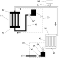
- FIG 3 is an explanatory view of a low temperature boiling cooling system in which the condenser of the present invention is located at the bottom or the side of the evaporator.
- FIG. 4 is a diagram illustrating another embodiment of the low temperature boiling cooling system in which the condenser of the present invention is located at the bottom or the side of the evaporator.
- FIG. 5 is a diagram illustrating a case where a gas-liquid separation tank is installed on an upper part of the evaporator of the present invention.
- FIG. 6 is a diagram illustrating a case where the present invention is applied to a refrigeration cycle using a compressor.
- FIG 7 is an explanatory view of applying the present invention to an absorption type refrigeration system.
- FIG. 8 is a diagram illustrating a case where the present invention is applied to a conventional steam equipment condenser system using a refrigerant vaporization heat.
- FIG. 9 is a diagram illustrating a case applied to a condenser system in which a ground condenser is additionally installed.
- FIG. 10 is a diagram illustrating a case where the present invention is applied to a fluid built-in cooling object.
- liquid refrigerant 30 refrigerant supply source
- liquid refrigerant collection tank 36 liquid refrigerant extraction pump
- liquid refrigerant withdrawal unit 51 gas-liquid separation tank
- Evaporation upper header 12 is installed on the upper part
- evaporation lower header 13 is installed on the lower part, and is composed of a plurality of evaporation tubes 14 interconnecting the evaporation upper header 12 and the evaporation lower header 13 and is cooled. Liquid on one side of the evaporator 11 and the evaporator lower header 13 of the evaporator 11 which are installed to be thermally coupled to the cooling target (not shown) so that the object (not shown) and the plurality of evaporation tubes 14 can exchange heat.
- the upper condensation header 16 is installed at the top
- the lower condensation header 17 is installed at the lower side and condensation with the condensation upper header 16
- the 16 is connected to the pipe so as to penetrate, and a liquid coolant outlet 39 for discharging the condensed liquid refrigerant 19 to one side of the condensation lower header 17 of the condenser 15 is provided to the refrigerant supply source ( 30), the evaporator 11, the pipe, the condenser 15, the liquid refrigerant withdrawal unit 39 in order to be connected in order to lower the pressure inside the evaporator 11 in the heat absorbed by the evaporator (11) It is characterized by consisting of a liquid refrigerant 19 that can boil at a lower internal pressure.
- the coolant supply source 30 may be composed of a coolant tank 31 connected to a coolant supply pipe 33 having a coolant control valve 32.
- the liquid coolant outlet 39 may be a one-way valve 34 or a liquid coolant collection tank. (35), the liquid refrigerant extraction pump 36 may be configured to pass through in order to be connected to the pipe.
- the liquid refrigerant 19 is one of liquefied gases including water and freon refrigerant. The principle of operation is as follows. When the liquid refrigerant 19 is supplied from the refrigerant supply source 30 into the evaporator 11 which is coupled to exchange heat with the cooling object (not shown) and absorbs heat from the cooling object (not shown), the liquid refrigerant is supplied at a low pressure.
- the vaporized gas refrigerant is introduced into the condenser (15) connected by a pipe and the gas refrigerant in the condenser (15) is liquefied to change the phase to a liquid refrigerant. Therefore, the heat supplied from the cooling target in the evaporator 11 performs a cooling function by removing heat from the condenser 15 to the outside of the cooling system.
- the liquid refrigerant liquefied in the condenser 15 is continuously drawn out through the liquid refrigerant outlet 39 so that the liquid refrigerant 19 is not filled in the condenser 15 so that the condenser 15 continues to serve as condensation. It can be done.
- the evaporator 11 which is installed to be thermally coupled to the cooling target (not shown) is evaporated in the evaporator 11 or the evaporator 11 which is coupled so that the evaporation tube 14 is in direct contact with the cooling target (not shown).
- a separate fluid circulation space (not shown) capable of heat exchange with the tube 14 is formed, and the fluid absorbing the heat contained in the cooling target (not shown) is circulated to the fluid circulation space (not shown) while the evaporation tube 14
- a vacuum pump 38 having a vacuum control valve 37 on one side of the cooling system so as to penetrate the inside of the cooling system in order to adjust the pressure in the cooling system.
- the difference between the temperature of the coolant flowing into the cooling device and the temperature of the cooling water flowing out is about 7 ° C, so the amount of cooling heat is about 7cal / g, and the amount of cooling water circulated to the cooling device is about 7cal / g. Determined by dividing.
- the latent heat of evaporation of water is about 540 cal / g, since the required amount of cooling water is only 1/70 to 1/80 as compared to the water cooling system, the amount of cooling water is greatly reduced, and the electrical energy circulating the cooling water is also great. Significantly reduced benefits are added.
- Evaporation upper header 12 is installed on the upper part
- evaporation lower header 13 is installed on the lower part, and is composed of a plurality of evaporation tubes 14 interconnecting the evaporation upper header 12 and the evaporation lower header 13 and is cooled.
- An evaporator 11 is installed to absorb heat from the cooling object by coupling to the heat exchange side.
- the condensation upper header 16 is installed at the upper part, and the condensation lower header 17 is installed at the lower part, and the condensation upper header 16 is installed.
- a condenser tube 18 interconnecting the condensation lower header 17 and installing a condenser 15 at a higher position than the evaporator to remove heat of vaporized refrigerant to the outside of the cooling system.
- the evaporation upper header 12 of the condenser 15 and the condensation upper header 16 of the condenser 15 are connected by a pipe, and the condensation lower header 17 of the condenser 15 and the evaporation lower header 13 of the evaporator 11.
- Evaporator, piping, condenser, piping, evaporator sequence Configure the cooling system constituting a closed circuit and fill the liquid coolant (19) to a surge of heat absorbed in the evaporator 11, the evaporator 11, lowering the pressure of the cooling system inside the space.
- the principle of operation is as follows.
- the liquid refrigerant 19 filled in the evaporator 11 is boiled into a gaseous state to ride the pipe. It is introduced into the condenser (15) to discard the heat to the outside and liquefied to flow through the pipe by gravity again into the evaporator (11) to complete a cycle of cooling to repeat this process to cool the cooling target (not shown).
- FIG. 2 is a diagram illustrating a problem that occurs when the condenser is located below the evaporator. If the condenser 15 is installed below the evaporator 11, since the liquid refrigerant 19 to be evaporated by the heat absorbed from the cooling target is filled inside the evaporator 11, it is naturally located below the evaporator 11. Since the liquid refrigerant 19 is also filled in the condenser 15 installed so that there is no space for gas refrigerant to enter the condenser 15, the condenser 15 may not serve as the condenser 15. Even if the condenser 15 is installed on the side of the same or almost the same height as the evaporator, a similar logic causes a problem that the condenser 15 cannot perform the role of the condenser 15.
- Evaporation upper header 12 is installed on the upper part
- evaporation lower header 13 is installed on the lower part, and is composed of a plurality of evaporation tubes 14 interconnecting the evaporation upper header 12 and the evaporation lower header 13 and is cooled.
- Liquid on one side of the evaporator 11 and the evaporator lower header 13 of the evaporator 11 which are installed to be thermally coupled to the cooling target (not shown) so that the object (not shown) and the plurality of evaporation tubes 14 can exchange heat.
- the upper condensation header 16 is installed at the top
- the lower condensation header 17 is installed at the lower side and condensation with the condensation upper header 16
- the 16 is connected to the pipe so as to penetrate, and a liquid coolant outlet 39 for discharging the condensed liquid refrigerant 19 to one side of the condensation lower header 17 of the condenser 15 is provided to the refrigerant supply source ( 30), the evaporator 11, the pipe, the condenser 15, the liquid refrigerant withdrawal unit 39 in order to be connected in order to lower the pressure inside the evaporator 11 in the heat absorbed by the evaporator (11) It is characterized by consisting of a liquid refrigerant 19 that can boil at a lower internal pressure.
- the coolant supply source 30 may be composed of a coolant tank 31 connected to a coolant supply pipe 33 having a coolant control valve 32.
- the liquid coolant outlet 39 may be a one-way valve 34 or a liquid coolant collection tank. (35), the liquid refrigerant extraction pump 36 may be configured to pass through in order to be connected to the pipe.
- the liquid refrigerant 19 is one of liquefied gases including water and freon refrigerant. The principle of operation is as follows. When the liquid refrigerant 19 is supplied from the refrigerant supply source 30 into the evaporator 11 which is coupled to exchange heat with the cooling object (not shown) and absorbs heat from the cooling object (not shown), the liquid refrigerant is supplied at a low pressure.
- the vaporized gas refrigerant is introduced into the condenser (15) connected by a pipe and the gas refrigerant in the condenser (15) is liquefied to change the phase to a liquid refrigerant. Therefore, the heat supplied from the cooling target in the evaporator 11 performs a cooling function by removing heat from the condenser 15 to the outside of the cooling system.
- the liquid refrigerant liquefied in the condenser 15 is continuously drawn out through the liquid refrigerant outlet 39 so that the liquid refrigerant 19 is not filled in the condenser 15 so that the condenser 15 continues to serve as condensation. It can be done.
- the evaporator 11 which is installed to be thermally coupled to the cooling target (not shown) is evaporated in the evaporator 11 or the evaporator 11 which is coupled so that the evaporation tube 14 is in direct contact with the cooling target (not shown).
- a separate fluid circulation space (not shown) capable of heat exchange with the tube 14 is formed, and the fluid absorbing the heat contained in the cooling target (not shown) is circulated to the fluid circulation space (not shown) while the evaporation tube 14
- a vacuum pump 38 having a vacuum control valve 37 on one side of the cooling system so as to penetrate the inside of the cooling system in order to adjust the pressure in the cooling system.
- FIG. 4 is a diagram illustrating another embodiment of the low temperature boiling cooling system in which the condenser of the present invention is located at the bottom or the side of the evaporator.
- the pipe drawn out from the liquid refrigerant drawing section 39 is extended to reuse the liquid refrigerant 19 drawn from the liquid refrigerant drawing section 39 as the refrigerant supply source 30 so as to evaporate the lower header of the evaporator 11. It is characterized by connecting to (13). In this case, it becomes a cooling system which comprises a closed circuit in order of the evaporator 11, the piping, the condenser 15, the liquid refrigerant
- FIG. 5 is a diagram illustrating a case where a gas-liquid separation tank is installed on an upper part of the evaporator of the present invention.
- Figure 3 or Figure 4 is characterized in that an additional cylindrical gas-liquid separation tank 51 is provided to the inside of the evaporation top header 12 of the evaporator 11 to pass through a plurality of tubes.
- the evaporator 11 continuously absorbs heat and the liquid refrigerant 19 absorbing the heat rises up to the gas-liquid separation tank 51 to separate gas and liquid.
- the gas refrigerant which is boiled, enters the condenser 15 through the pipe.
- the non-boiling liquid refrigerant 19 is lowered back to the evaporator 11 to absorb more heat to boil.
- the operating principle is the same as 3 or 4.
- FIG. 6 is a diagram illustrating a case where the present invention is applied to a refrigeration cycle using a compressor.
- a refrigeration system including a refrigerator / air conditioner using a compressor
- the capacity of the compressor must be very large. Therefore, install a freezer evaporator 61 at a place that absorbs heat.
- the compressor 62 and the heat exchanger 63 for the condenser are installed near the freezer evaporator 61, and the freezer evaporator 61, the compressor 62, the heat exchanger 63 for the condenser, the expansion valve 64, and the freeze evaporator 61 again.
- the refrigeration system forms a closed circuit with pipes in the order of).
- the heat exchanger 63 for the condenser is configured such that a working fluid space (not shown) through which a refrigeration cycle working fluid circulates and a refrigerant accommodating space (not shown) for cooling it may be mutually heat exchanged, and a heat exchanger 63 for a condenser.
- the method of disposing heat at a place where the heat can be discarded by constructing another cooling system that circulates and cools the refrigerant storage space (not shown) of the refrigerant storage space of the condenser heat exchanger 63 has been described. ), Water cooling is adopted to force the cooling water to circulate.
- the evaporator 11 of the present invention is configured to replace the refrigerant receiving space (not shown) of the heat exchanger 63 for the condenser of the refrigeration system using the compressor.
- Industrial Applicability The present invention can be applied to an ice-making refrigeration system such as an industrial refrigeration system, a refrigeration system for a large air conditioning system, an ice making facility, and an ice rink.
- the principle of operation is as follows.
- the condenser heat exchanger 63 serves as the evaporator 11, so that the refrigerant system is operated so that the hot refrigerant compressed by the compressor 62 is a working fluid space of the condenser heat exchanger 63 (not shown).
- the liquid refrigerant 19 supplied to the refrigerant receiving space (not shown) serving as the evaporator 11 is formed so as to exchange heat with each other.
- the remaining operation principle is as described in FIG.
- the heat generated inside the refrigerator is discarded in the indoor space.
- the present invention is very effective because it can prevent the temperature rise of the indoor space by throwing away the heat to a distant place without using additional energy.
- the present invention can prevent pollution caused by hot air from the outdoor unit, thereby making a very pleasant environment.
- Absorption refrigeration system (74) is a new concept of refrigeration system that cools while repeating the process of reducing the water by boiling the water at a low pressure at a low temperature and the absorbent concentration.
- Absorption refrigeration system 74 has to adopt a cooling method for circulating the refrigerant in the absorber heat exchanger 71 and the condenser heat exchanger 72 formed in the structure.
- the evaporator 11 of the present invention is configured to replace the absorption chiller heat exchanger 73 of the absorption refrigeration system 74.
- the principle of operation is as follows. In the case of applying the present invention, since the absorption chiller heat exchanger 73 serves as the evaporator 11, when the absorption chiller system 74 operates, heat is supplied to the liquid refrigerant 19 supplied to the absorption chiller heat exchanger 73. do. The remaining operation principle is as described in FIG.
- FIG. 8 is a diagram illustrating a case where the present invention is applied to a conventional steam equipment condenser system using a refrigerant vaporization heat. It is an example of applying the present invention to the cooling device described in Application No. 10-2009-0021939 [Steam facility condenser system using refrigerant vaporization heat].
- the evaporator 11 of the present invention is characterized in that it replaces the refrigerant using multiplexer 80 of the steam equipment condenser system using the refrigerant vaporization heat. Since the condenser has to discard a large amount of heat, the condenser 15 is very effective if it can be installed in the river / sea / land to use natural cold heat.
- the operating principle is as described in FIG.
- a closed circuit cooling system may be configured as shown in FIG.
- the water which is the liquid refrigerant 19 condensed in the condenser 15 installed in the water or in the ground, but the new coolant is continued from the coolant supply source 30.
- the cooling system is simplified, the equipment to be maintained / repaired is reduced, and the electricity for cooling water supply is also saved.
- FIG. 9 is a diagram illustrating a case applied to a condenser system in which a ground condenser is additionally installed.
- the circulation direction switching valve 92 is additionally installed in the pipe connecting the refrigerant use condenser 80 and the condenser 15, and T-branches so that the pipes pass through the piping in front of the circulation direction switching valve 92.
- T-branched After connecting to the same pipe, one end is connected so as to T-branched to penetrate the pipes in the rear pipe of the circulation direction switching valve 92.
- the principle of operation is as follows.
- the condenser 15 needs to increase the cooling effect by operating the ground condenser 91 when the temperature of the ground is low, even if installed in the river / sea / ground. If the open condensation actuating valve 93 is opened and the ground condensation actuating valve 93 is closed, the ground condenser 91 does not participate in the cooling activity, and the ground condensing actuation valve 92 is closed and the ground condensing actuating valve 93 is opened. The condensers 91 participate in the cooling activity.
- FIG. 10 is a diagram illustrating a case where the present invention is applied to a fluid built-in cooling object.
- PAD transformer aka PAD transformer
- PAD transformer ground-mounted transformer
- columnar transformer aka computer system / computer, and general mechanical device
- the fluid receiving space (not shown) and the refrigerant containing space (not shown) are provided with a heat exchange type evaporator 103 formed to allow mutual heat exchange and the fluid formed inside the cooling object 101.
- a refrigerant is circulated and cooled by using natural refrigerant or a refrigerant boiled at a low temperature.
- the condenser must be installed above the evaporator. Due to the conditions, it is difficult to select a condenser location, and in order to take advantage of natural cold heat in the river / sea / land, the condenser must be lowered under the evaporator.
- the liquid refrigerant 19 is continuously supplied to the evaporator 11 and condensed in the condenser 15.
- the liquid refrigerant 19 is continuously removed by the liquid refrigerant drawing pump 36 to secure a condensation space.
- (15) is installed on the bottom or side of the evaporator (11) to perform the cooling function to solve all the restrictions on the installation position of the condenser (15)
- the latent heat of water evaporation is about 540 cal / g Therefore, the required amount of cooling water is only 1/70 to 1/80 compared to the water cooling system, which can greatly reduce the amount of cooling water. Therefore, it will make a great contribution in terms of energy saving and environmental protection. will be.
Landscapes
- Engineering & Computer Science (AREA)
- Physics & Mathematics (AREA)
- Mechanical Engineering (AREA)
- Thermal Sciences (AREA)
- General Engineering & Computer Science (AREA)
- Cooling Or The Like Of Electrical Apparatus (AREA)
Abstract
본 발명은 냉매(물과 프레온냉매를 포함한 액화가스)의 증발과 응축의 원리를 이용하여 냉장고/에어컨디셔너를 포함한 냉동시스템(흡수식냉동시스템 포함), 발전기의 복수기, 변압기를 포함한 전력설비, 유체순환으로 냉각하는 기계장치, 유체순환으로 냉각시키는 전산시스템/전산실 등에서 발생하는 열을 제거시키기 위한 냉각시스템에 있어서 응축기를 증발기 보다 하부 또는 증발기 측부에 위치하도록 하는 응축기가 증발기 하부 또는 측부에 위치하는 저온비등 냉각시스템에 관한 것이다. 열교환기를 사용하는 냉각시스템에 있어서 종래의 일반적인 기술은 열교환기 내부의 물을 물펌프를 사용하여 강제순환시키는 수냉각 방식이다. 최근에는 수냉각을 대신하여 저온에서 비등하는 냉매나 액화가스를 끓여서 자연순환시키는 방식이 개발되어 일부 기기에 적용되고 있다. 특히 본 출원인은 출원번호 10-2011-0048210[물의 저온비등 자연순환 냉각시스템]을 통하여 물이 낮은 압력에서는 저온에서 비등하는 원리를 적용한 냉각시스템을 제시한 바 있다. 그러나 상기 발명들에 있어서는 응축기에서 응축된 냉매를 중력에 의한 자연순환으로 순환하게 하려고 의도하였으므로 응축기가 증발기 역할을 하는 보일러용열교환기보다 상부에 존재하여야 하는 제약이 있었다. 본 발명은 응축기를 증발기 보다 하부 또는 유사한 높이인 증발기 측부에 위치하도록 하여 응축기의 설치위치에 대한 제약을 없애는 것이 핵심이다. 응축기에서 응축된 냉매(물과 프레온냉매를 포함한 액화가스)를 펌프로 인출시켜 응축기 내부공간이 액체냉매로 채워지는 것을 막음으로써 응축기의 지속적인 역할이 수행되도록 한다. 이렇게 되면 응축기를 증발기 옆의 지상이나 자연 냉열을 이용하는 지중, 강물, 해수 속에 잠기게 할 수 있어서 응축기를 증발기보다 항상 상부에 설치하여야 하는 응축기 설치공간의 제약을 탈피할 수 있을 뿐 만 아니라 냉각에 자연의 냉열을 이용할 수 있으므로 냉각시스템의 냉각효율을 획기적으로 향상시킬 수 있게 된다.
Description
냉각장치 구조 설계분야
냉장고/에어컨디셔너를 포함한 냉동시스템(흡수식냉동시스템 포함), 변압기를 포함한 전력설비, 유체순환으로 냉각시키는 기계장치, 유체순환으로 냉각시키는 전산시스템/전산실 등은 기기가 작동을 하게 되면 열이 발생한다. 종래 기술은 발생한 열을 배출하기 위하여 상기 설비들을 수냉각방식으로 냉각하는 것이 일반적이다. 최근에는 물펌프를 사용하지 않고 물 대신 저온에서 비등하는 냉매나 액화가스를 작동유체로 하여 자연순환시키는 방식이 개발되어 일부 설비에 사용 중이다. 특히 본 출원인은 출원번호 10-2011-0048210[물의 저온비등 자연순환 냉각시스템]을 통하여 물이 낮은 압력에서는 저온에서 비등하는 원리를 적용한 냉각시스템을 제시한 바 있다. 그러나 상기 발명들에 있어서는 응축기에서 응축된 냉매를 중력에 의한 자연순환으로 순환하게 하려고 의도하였으므로 응축기가 증발기 역할을 하는 보일러용열교환기보다 상부에 존재하여야 하는 물리적인 제약이 있었다.
본 발명에서는 응축기를 증발기보다 하부 또는 증발기 측부에 위치하도록 하여 응축기의 설치위치에 대한 제약을 없애도록 한다. 응축기에서 응축된 냉매(물과 프레온냉매를 포함한 액화가스)를 펌프로 외부로 인출시켜 응축기 내부공간이 액체냉매로 채워지는 것을 막음으로써 응축기의 지속적인 역할이 수행되도록 한다. 증발잠열이 큰 냉매를 사용하여 냉매의 순환량이 적어도 효율이 높은 냉각성능을 발휘하도록 하며 응축기를 증발기 옆의 지상이나 자연의 냉열을 이용하는 지중, 해수, 강물 속에 잠기게 할 수 있도록 하여 냉각에 자연의 냉열을 이용할 수 있도록 한다.
응축기를 증발기의 측부 또는 하부에 설치하고 증발기 상부와 응축기 상부를 배관으로 연결한 다음 냉각회로 내부의 압력을 낮게 하여 액체냉매가 낮은 온도에서 비등할 수 있도록 하고, 증발기에는 액체냉매를 공급하는 냉매공급원을 연결하여 액체냉매가 기화하면서 냉각대상으로부터 열을 흡수하여 냉각을 하고 응축기에는 액체냉매인출부를 설치하여 응축기에서 열을 외부로 버리고 내부에서 액화된 액체냉매를 외부로 계속 배출시켜 냉각시스템이 지속적으로 작동하도록 함.
각종기기는 작동을 하면서 열을 발생시키고 그 열을 제거시키는 것은 그 기기가 잘 작동되도록 하는 것 뿐 만 아니라 수명과 용량증대에도 한 몫을 하는 매우 중요한 작업 중의 하나이다. 기존의 냉각방식은 물을 강제로 순환시키며 냉각하는 수냉각 방식이 보편적인 것이며 최근에 저온에서 비등하는 냉동사이클에서 사용하는 냉매 또는 액화가스를 사용하여 냉매를 자연순환 방식으로 순환시키며 냉각하는 방식이 변압기 냉각장치에 도입되었다. 수냉각방식은 냉각에 비용이 많이 들고 냉매를 자연순환하는 방식은 응축기를 증발기보다 상부에 설치하여야 하는 제약조건이 있어서 응축기 입지선정에 어려움이 있고, 특히 강/바다/땅 속의 자연의 냉열을 이용하려면 응축기가 증발기 하부로 내려와야 하는데 구현시킬 수가 없었다.
본 발명에서는 증발기(11)에는 액체냉매(19)를 지속적으로 공급하고 응축기(15)에 응축되어 고이는 액체냉매(19)는 지속적으로 액체냉매인출펌프(36)로 제거시켜 응축공간을 확보함으로써 응축기(15)가 증발기(11)의 하부나 측부에 설치되더라도 냉각기능을 수행하도록 하여 응축기(15)의 설치위치에 대한 제약을 모두 해소시켰다. 수냉각방식에 의한 냉각의 경우 냉각장치로 유입되는 냉각수 온도와 유출되는 냉각수 온도차이가 약7℃이므로 냉각열량은 약7cal/g이며 냉각장치로 순환하는 냉각수 량은 냉각대상열량을 7cal/g로 나누어서 결정된다. 본 발명의 경우 물의 증발잠열이 약540cal/g이므로 필요한 냉각수 량이 수냉각방식 냉각장치에 비하여 1/70 내지 1/80에 불과하므로 냉각수 량을 엄청나게 줄일 수 있는 장점이 있으며 냉각수를 순환시키는 전기에너지도 획기적으로 줄어드는 이득이 추가된다.
도 1은 기존의 자연순환 냉각시스템 설명도이다.
도 2는 응축기가 증발기 하부에 위치할 경우 발생하는 문제점 설명도이다.
도 3은 본 발명의 응축기가 증발기 하부 또는 측부에 위치하는 저온비등 냉각시스템 설명도이다.
도 4는 본 발명의 응축기가 증발기 하부 또는 측부에 위치하는 저온비등 냉각시스템의 다른 실시 사례 설명도이다.
도 5는 본 발명의 증발기 상부에 기액분리탱크가 설치된 사례 설명도이다.
도 6은 본 발명을 압축기 사용 냉동사이클에 적용한 사례 설명도이다.
도 7은 본 발명을 흡수식냉동시스템에 적용한 사례 설명도이다.
도 8은 본 발명을 기존의 냉매 기화열을 이용한 증기설비 복수기 시스템에 적용한 사례 설명도이다.
도 9는 지상응축기가 추가로 설치된 복수기 시스템에 적용한 사례 설명도이다.
도 10은 본 발명을 유체내장냉각대상에 적용한 사례 설명도이다.
[부호설명]
11 : 증발기 12 : 증발상부헤더
13 : 증발하부헤더 14 : 증발관
15 : 응축기 16 : 응축상부헤더
17 : 응축하부헤더 18 : 응축관
19 : 액체냉매 30 : 냉매공급원
31 : 냉매탱크 32 : 냉매조절밸브
33 : 냉매공급배관 34 : 일방향밸브
35 : 액체냉매수집탱크 36 : 액체냉매인출펌프
37 : 진공조절밸브 38 : 진공펌프
39 : 액체냉매인출부 51 : 기액분리탱크
61 : 냉동증발기 62 : 압축기
63 : 응축기용열교환기 64 : 팽창변
71 : 흡수기열교환기 72 : 응축기열교환기
73 : 흡수식냉동기열교환기 74 : 흡수식냉동시스템
80 : 냉매사용복수기 84 : 보일러
85 : 고압터빈 86 : 저압터빈
87 : 공급수펌프 91 : 지상응축기
92 : 순환방향전환밸브 93 : 지상응축기가동밸브
101 : 유체내장냉각대상 102 : 유체순환펌프
103 : 열교환형증발기
상부에 증발상부헤더(12)가 설치되며 하부에 증발하부헤더(13)가 설치되고 증발상부헤더(12)와 증발하부헤더(13)를 상호 연결하는 다수의 증발관(14)으로 구성되며 냉각대상(미도시)과 다수의 증발관(14)이 열교환이 가능하도록 냉각대상(미도시)과 열적으로 결합되도록 설치되는 증발기(11)와 증발기(11)의 증발하부헤더(13) 일측에 액체냉매(19)를 공급하는 냉매공급원(30)을 관통되도록 배관으로 연결하고, 상부에 응축상부헤더(16)가 설치되며 하부에 응축하부헤더(17)가 설치되고 응축상부헤더(16)와 응축하부헤더(17)를 상호 연결하는 다수의 응축관(18)으로 구성되며 기화한 냉매가 지닌 열을 외부로 제거하고 기화한 냉매를 응축시키는 응축기(15)를 증발기(11)의 하부 또는 측부에 위치하도록 설치하고, 증발기(11)의 증발상부헤더(12)와 응축기(15)의 응축상부헤더(16)가 관통하도록 배관으로 연결하고, 응축기(15)의 응축하부헤더(17) 일측에 응축된 액체냉매(19)를 외부로 유출시키는 액체냉매인출부(39)를 설치하여 냉매공급원(30), 증발기(11), 배관, 응축기(15), 액체냉매인출부(39)의 순서로 연결되도록 하고 그 내부 공간의 압력을 낮게 하고 증발기(11) 내부에는 증발기(11)에서 흡수한 열에 의해 낮아진 내부 압력에서 비등할 수 있는 액체냉매(19)를 채워서 구성하는 것이 특징이다. 냉매공급원(30)이 냉매조절밸브(32)가 달린 냉매공급배관(33)에 연결된 냉매탱크(31)로 구성될 수 있고 액체냉매인출부(39)가 일방향밸브(34), 액체냉매수집탱크(35), 액체냉매인출펌프(36) 순서로 관통하며 배관으로 연결되도록 구성될 수도 있다. 액체냉매(19)는 물과 프레온냉매를 포함한 액화가스 중의 하나로 한다. 작동원리는 다음과 같다. 냉각대상(미도시)과 열교환하도록 결합하여 냉각대상(미도시)으로부터 열을 흡수하는 증발기(11) 내부로 냉매공급원(30)에서 액체냉매(19)를 공급하면 액체냉매는 내부의 낮은 압력에서 낮은 온도에서 비등하여 기화를 하고, 기화한 기체냉매는 배관으로 연결된 응축기(15) 내부로 유입되며 응축기(15) 내부에서 기체냉매는 열을 버리고 액화되어 액체냉매로 상변화를 한다. 따라서 증발기(11)에서 냉각대상으로부터 공급받은 열은 응축기(15)에서 냉각시스템 외부로 열을 제거시킴으로써 냉각기능을 수행한다. 응축기(15)에서 액화된 액체냉매는 액체냉매인출부(39)를 통하여 외부로 계속 인출시킴으로써 응축기(15) 내부에 액체냉매(19)가 채워지지 않도록 하여 응축기(15)가 응축의 역할을 계속 수행할 수 있도록 할 수 있다. 냉각대상(미도시)과 열적으로 결합되도록 설치되는 증발기(11)가 증발관(14)이 직접적으로 냉각대상(미도시)과 접촉하여 열교환하도록 결합되는 증발기(11) 또는 증발기(11)에 증발관(14)과 열교환이 가능한 별도의 유체순환공간(미도시)을 형성시키고 이 유체순환공간(미도시)으로 냉각대상(미도시)에 내장된 열을 흡수한 유체가 순환하면서 증발관(14)과 열교환하도록 결합되는 증발기(11) 중의 하나인 것도 본 발명의 범위에 포함된다. 냉각시스템 내부의 압력을 조절하기 위하여 냉각시스템 내부와 관통되도록 냉각시스템 일측에 진공조절밸브(37)가 달린 진공펌프(38)를 추가로 설치하여 구성하는 것도 본 발명의 범위에 포함된다.
수냉각방식에 의한 냉각의 경우 냉각장치로 유입되는 냉각수 온도와 유출되는 냉각수 온도차이가 약7℃이므로 냉각열량은 약7cal/g이며 냉각장치로 순환하는 냉각수 량은 냉각대상열량을 7cal/g로 나누어서 결정된다. 본 발명의 경우 물의 증발잠열이 약540cal/g이므로 필요한 냉각수 량이 수냉각방식 냉각장치에 비하여 1/70 내지 1/80에 불과하므로 냉각수 량을 엄청나게 줄일 수 있는 장점이 있으며 냉각수를 순환시키는 전기에너지도 획기적으로 줄어드는 이득이 추가된다.
도 1은 기존의 자연순환 냉각시스템 설명도이다. 상부에 증발상부헤더(12)가 설치되며 하부에 증발하부헤더(13)가 설치되고 증발상부헤더(12)와 증발하부헤더(13)를 상호 연결하는 다수의 증발관(14)으로 구성되며 냉각대상과 열교환 측면으로 결합하여 냉각대상으로부터 열을 흡수하는 증발기(11)를 설치하고, 상부에 응축상부헤더(16)가 설치되며 하부에 응축하부헤더(17)가 설치되고 응축상부헤더(16)와 응축하부헤더(17)를 상호 연결하는 다수의 응축관(18)으로 구성되며 기화한 냉매의 열을 냉각시스템 외부로 제거하는 응축기(15)를 증발기보다 높은 위치에 설치하고, 증발기(11)의 증발상부헤더(12)와 응축기(15)의 응축상부헤더(16)가 관통하도록 배관으로 연결하고, 응축기(15)의 응축하부헤더(17)와 증발기(11)의 증발하부헤더(13)가 통하도록 배관으로 연결하여 증발기, 배관, 응축기, 배관, 다시 증발기 순서로 폐회로를 구성하는 냉각시스템을 구성하고 냉각시스템 내부 공간의 압력을 낮추고 증발기(11) 내부에는 증발기(11)에서 흡수한 열로 비등할 수 있는 액체냉매(19)를 채운다. 작동원리는 다음과 같다. 냉각대상(미도시)과 열교환 측면으로 결합된 증발기(11)가 냉각대상(미도시)으로부터 열을 흡수하면 증발기(11) 내부에 채워진 액체냉매(19)는 비등하여 기체상태가 되어 배관을 타고 응축기(15)로 유입되어 외부로 열을 버리고 액화되어 중력에 의해 배관을 타고 다시 증발기(11)로 유입되어 냉각의 한 주기를 마치며 이 과정을 반복하며 냉각대상(미도시)을 냉각시키게 된다. 응축기(15)가 성능을 제대로 발휘하려면 응축기(15) 내부공간에는 상시 액체냉매가 잔류하지 않도록 액체냉매(19)가 채워진 증발기(11)보다 상부에 설치되어야 하는 제약이 있다.
도 2는 응축기가 증발기 하부에 위치할 경우 발생하는 문제점 설명도이다. 응축기(15)를 증발기(11)보다 하부에 위치하도록 설치하면, 증발기(11) 내부에는 냉각대상으로부터 흡수한 열에 의해 증발할 액체냉매(19)가 채워져야 하므로 당연히 증발기(11)보다 하부에 위치하도록 설치된 응축기(15)에도 액체냉매(19)가 채워지므로 응축기(15)에 기체냉매가 들어올 공간이 없어서 응축기(15)는 응축기(15)의 역할을 수행할 수 없다. 응축기(15)를 증발기와 동등하거나 거의 같은 높이인 측부에 설치하여도 유사한 논리로 응축기(15)는 응축기(15)의 역할을 수행할 수 없는 문제점이 발생한다.
도 3은 본 발명의 응축기가 증발기 하부 또는 측부에 위치하는 저온비등 냉각시스템 설명도이다. 상부에 증발상부헤더(12)가 설치되며 하부에 증발하부헤더(13)가 설치되고 증발상부헤더(12)와 증발하부헤더(13)를 상호 연결하는 다수의 증발관(14)으로 구성되며 냉각대상(미도시)과 다수의 증발관(14)이 열교환이 가능하도록 냉각대상(미도시)과 열적으로 결합되도록 설치되는 증발기(11)와 증발기(11)의 증발하부헤더(13) 일측에 액체냉매(19)를 공급하는 냉매공급원(30)을 관통되도록 배관으로 연결하고, 상부에 응축상부헤더(16)가 설치되며 하부에 응축하부헤더(17)가 설치되고 응축상부헤더(16)와 응축하부헤더(17)를 상호 연결하는 다수의 응축관(18)으로 구성되며 기화한 냉매가 지닌 열을 외부로 제거하고 기화한 냉매를 응축시키는 응축기(15)를 증발기(11)의 하부 또는 측부에 위치하도록 설치하고, 증발기(11)의 증발상부헤더(12)와 응축기(15)의 응축상부헤더(16)가 관통하도록 배관으로 연결하고, 응축기(15)의 응축하부헤더(17) 일측에 응축된 액체냉매(19)를 외부로 유출시키는 액체냉매인출부(39)를 설치하여 냉매공급원(30), 증발기(11), 배관, 응축기(15), 액체냉매인출부(39)의 순서로 연결되도록 하고 그 내부 공간의 압력을 낮게 하고 증발기(11) 내부에는 증발기(11)에서 흡수한 열에 의해 낮아진 내부 압력에서 비등할 수 있는 액체냉매(19)를 채워서 구성하는 것이 특징이다. 냉매공급원(30)이 냉매조절밸브(32)가 달린 냉매공급배관(33)에 연결된 냉매탱크(31)로 구성될 수 있고 액체냉매인출부(39)가 일방향밸브(34), 액체냉매수집탱크(35), 액체냉매인출펌프(36) 순서로 관통하며 배관으로 연결되도록 구성될 수도 있다. 액체냉매(19)는 물과 프레온냉매를 포함한 액화가스 중의 하나로 한다. 작동원리는 다음과 같다. 냉각대상(미도시)과 열교환하도록 결합하여 냉각대상(미도시)으로부터 열을 흡수하는 증발기(11) 내부로 냉매공급원(30)에서 액체냉매(19)를 공급하면 액체냉매는 내부의 낮은 압력에서 낮은 온도에서 비등하여 기화를 하고, 기화한 기체냉매는 배관으로 연결된 응축기(15) 내부로 유입되며 응축기(15) 내부에서 기체냉매는 열을 버리고 액화되어 액체냉매로 상변화를 한다. 따라서 증발기(11)에서 냉각대상으로부터 공급받은 열은 응축기(15)에서 냉각시스템 외부로 열을 제거시킴으로써 냉각기능을 수행한다. 응축기(15)에서 액화된 액체냉매는 액체냉매인출부(39)를 통하여 외부로 계속 인출시킴으로써 응축기(15) 내부에 액체냉매(19)가 채워지지 않도록 하여 응축기(15)가 응축의 역할을 계속 수행할 수 있도록 할 수 있다. 냉각대상(미도시)과 열적으로 결합되도록 설치되는 증발기(11)가 증발관(14)이 직접적으로 냉각대상(미도시)과 접촉하여 열교환하도록 결합되는 증발기(11) 또는 증발기(11)에 증발관(14)과 열교환이 가능한 별도의 유체순환공간(미도시)을 형성시키고 이 유체순환공간(미도시)으로 냉각대상(미도시)에 내장된 열을 흡수한 유체가 순환하면서 증발관(14)과 열교환하도록 결합되는 증발기(11) 중의 하나인 것도 본 발명의 범위에 포함된다. 냉각시스템 내부의 압력을 조절하기 위하여 냉각시스템 내부와 관통되도록 냉각시스템 일측에 진공조절밸브(37)가 달린 진공펌프(38)를 추가로 설치하여 구성하는 것도 본 발명의 범위에 포함된다.
도 4는 본 발명의 응축기가 증발기 하부 또는 측부에 위치하는 저온비등 냉각시스템의 다른 실시 사례 설명도이다. 도3에서 냉매공급원(30)으로 액체냉매인출부(39)에서 인출되는 액체냉매(19)를 재사용하기 위하여 액체냉매인출부(39)에서 인출되는 배관을 연장하여 증발기(11)의 증발하부헤더(13)에 연결시켜 구성하는 것이 특징이다. 이 경우 증발기(11), 배관, 응축기(15), 액체냉매인출부(39), 다시 증발기(11) 순서로 폐회로를 구성하는 냉각시스템이 된다. 사용한 액체냉매(19)를 버리고 새로운 액체냉매(19)를 지속적으로 공급할 수 없는 경우에 적합한 방식이다. 작동원리는 도3과 유사하나 액체냉매인출부(39)에서 인출된 액체냉매(19)가 연장된 배관을 통하여 증발기(11)의 증발하부헤더(13)로 유입되어 증발기(11)에 액체냉매(19)를 공급하는 것이 다르다.
도 5는 본 발명의 증발기 상부에 기액분리탱크가 설치된 사례 설명도이다. 도3이나 도4에서 증발기(11)의 증발상부헤더(12) 상부에 다수의 관으로 관통하도록 내부가 비어 있는 통형인 기액분리탱크(51)를 추가로 설치하여 구성하는 것이 특징이다. 이 경우 증발기(11)에서는 열을 계속 흡수하고 열을 흡수한 액체냉매(19)는 기액분리탱크(51)로 올라와서 기체와 액체가 분리되는데 비등한 기체냉매는 배관을 타고 응축기(15)로 유입되며 비등하지 않은 액체냉매(19)는 다시 증발기(11)로 내려가서 열을 더 흡수하여 비등을 하게 된다. 작동원리는 3 또는 도4와 같다.
도 6은 본 발명을 압축기 사용 냉동사이클에 적용한 사례 설명도이다. 압축기를 이용하는 냉장고/에어컨디셔너를 포함한 냉동시스템의 경우 열을 흡수하는 장소와 열을 버릴 수 있는 장소가 멀리 떨어져 있을 경우 압축기의 용량이 매우 커져야 하므로 열을 흡수하는 장소에 냉동증발기(61)를 설치하고 냉동증발기(61) 인근에 압축기(62)와 응축기용열교환기(63)를 설치하여 냉동증발기(61), 압축기(62), 응축기용열교환기(63), 팽창변(64) 다시 냉동증발기(61)의 순서로 배관으로 폐회로를 형성하는 냉동시스템을 구성한다. 응축기용열교환기(63)는 냉동사이클 작동유체가 순환하는 작동유체공간(미도시)과 이를 냉각시키는 냉매수용공간(미도시)이 상호 열교환을 할 수 있도록 구성되며, 응축기용열교환기(63)의 냉매수용공간(미도시)을 순환하면서 냉각시키는 또 다른 냉각시스템을 구성하여 멀리 떨어진 열을 버릴 수 있는 장소에서 열을 버리는 방법이 지금까지는 응축기용열교환기(63)의 냉매수용공간(미도시)에 냉각수를 강제적으로 순환시키는 수냉각방식을 채택하고 있다. 본 발명을 압축기를 이용하는 냉동시스템에 적용하기 위하여 본 발명의 증발기(11)로 압축기를 이용하는 냉동시스템의 응축기용열교환기(63)의 냉매수용공간(미도시)을 대체하여 구성하는 것이 특징이다. 산업용 냉동시스템, 대형 공조설비의 냉동시스템, 제빙설비 및 아이스링크 등 제빙용 냉동시스템에 본 발명을 적용할 수 있다. 작동원리는 다음과 같다. 본 발명을 적용할 경우 응축기용열교환기(63)는 증발기(11) 역할을 하므로 냉동시스템이 작동하여 압축기(62)에서 압축된 뜨거운 냉매가 응축기용열교환기(63)의 작동유체공간(미도시)으로 들어오면 이와 상호 열교환이 가능하도록 형성된 증발기(11) 역할을 하는 냉매수용공간(미도시)에 공급된 액체냉매(19)에 열이 공급된다. 나머지 작동원리는 도4에서 설명한 바와 같다. 냉장고 내부에서 발생한 열을 실내공간에 버리게 되는데 본 발명을 적용하면 추가적 에너지를 사용하지 않고 그 열을 멀리 떨어져 있는 외부로 버려서 실내공간의 온도상승을 막을 수 있어서 매우 효과적이다. 에어컨디셔너의 경우에도 본 발명을 적용하면 실외기에서 나오는 더운 공기에 의한 공해를 막을 수 있어서 매우 쾌적한 환경을 만들 수 있다.
도 7은 본 발명을 흡수식냉동시스템에 적용한 사례 설명도이다. 흡수식냉동시스템(74)의 경우 물이 낮은 압력에서 낮은 온도에서 비등한다는 원리와 흡습제 농도를 열을 가하여 환원시키는 과정을 반복하면서 냉각을 시키는 새로운 개념의 냉동시스템이다. 흡수식냉동시스템(74)은 구조상 내부에 형성되어 있는 흡수기열교환기(71)와 응축기열교환기(72) 등에 냉매를 순환시키는 냉각방식을 채택할 수 밖에 없다. 흡수기열교환기(71)와 응축기열교환기(72) 등 냉각이 필요한 열교환기를 모두 합쳐서 흡수식냉동기열교환기(73)라 칭한다. 본 발명을 흡수식냉동시스템(74)에 적용하기 위하여 본 발명의 증발기(11)로 흡수식냉동시스템(74)의 흡수식냉동기열교환기(73)를 대체하여 구성하는 것이 특징이다. 작동원리는 다음과 같다. 본 발명을 적용할 경우 흡수식냉동기열교환기(73)는 증발기(11) 역할을 하므로 흡수식냉동시스템(74)이 작동하면 흡수식냉동기열교환기(73) 내부에 공급된 액체냉매(19)에 열이 공급된다. 나머지 작동원리는 도4에서 설명한 바와 같다.
도 8은 본 발명을 기존의 냉매 기화열을 이용한 증기설비 복수기 시스템에 적용한 사례 설명도이다. 출원번호 10-2009-0021939호[냉매 기화열을 이용한 증기설비 복수기 시스템]에 제시된 냉각장치에 본 발명을 적용한 사례이다. 본 발명의 증발기(11)로 냉매 기화열을 이용한 증기설비 복수기 시스템의 냉매사용복수기(80)를 대체하여 구성하는 것이 특징이다. 복수기는 많은 량의 열을 버려야 하므로 응축기(15)는 강/바다/땅 속에 설치하여 자연의 냉열을 이용할 수 있으면 매우 효과적이다. 작동원리는 도3에서 설명한 바와 같다. 냉매사용복수기(80)와 응축기(15)의 설치위치가 가까운 경우에는 도4와 같이 폐회로 냉각시스템을 구성할 수도 있다. 그러나 냉매사용복수기(80) 근처에서 냉각수 조달이 가능할 경우 구태여 물속이나 땅속에 설치한 응축기(15)에서 응축된 액체냉매(19)인 물을 재사용할 것이 아니라 새로운 냉각수를 냉매공급원(30)에서 계속 공급하고 액체냉매인출부(39)에서 응축된 액체냉매(19)인 물을 인출하여 버리면 냉각시스템도 간단해지고, 유지/보수할 설비도 줄어들며, 냉각수공급용 전기도 많이 절약되는 장점이 존재한다.
도 9는 지상응축기가 추가로 설치된 복수기 시스템에 적용한 사례 설명도이다. 도8에서 냉매사용복수기(80)와 응축기(15)를 연결하는 배관에 순환방향전환밸브(92)를 추가로 설치하고, 순환방향전환밸브(92) 앞부분 배관에서 배관끼리 관통하도록 T분기하여 배관을 설치하여 지상응축기가동밸브(93)를 설치하고 그 후단 배관에 다수의 지상응축기(91) 응축상부헤더(16)들을 병렬로 연결하고, 다수의 지상응축기(91) 응축하부헤더(17) 들을 동일한 배관에 연결한 다음 그 일측 단부를 순환방향전환밸브(92) 뒷부분 배관에서 배관끼리 관통하도록 T분기되도록 연결한다. 작동원리는 다음과 같다. 추운 날은 대기 온도가 강/바다/땅 속의 온도보다 낮다. 따라서 더운 날씨를 대비하여 응축기(15)는 강/바다/땅 속에 설치하더라도 지상의 온도가 낮을 경우 지상응축기(91)를 가동시켜 냉각효과를 높일 필요가 있다. 순환방향전환밸브(92)를 열고 지상응축기가동밸브(93)를 잠그면 지상응축기(91)는 냉각활동에 참여하지 않으며, 순환방향전환밸브(92)를 닫고 지상응축기가동밸브(93)를 열면 지상응축기(91)들은 냉각활동에 참여하게 된다.
도 10은 본 발명을 유체내장냉각대상에 적용한 사례 설명도이다. 냉각용 유체를 내장하고 냉각용 유체를 순환시키면서 냉각시키는 OF케이블, 유입변압기, 몰드변압기, 가스변압기, 리액터, 발전기고정자, 발전기회전자, 전기자동차용 전동기고정자, 전동기고정자, 리니어모터 고정자, 전동기회전자, 지하매립변압기, 옥내변압기, 옥외변압기, 지상설치변압기(일명 PAD변압기), 주상변압기, 전산시스템/전산실, 일반기계장치 중의 하나가 유체내장냉각대상(101)이다. 본 발명을 적용하기 위하여 유체수용공간(미도시)과 냉매수용공간(미도시)이 상호 열교환을 할 수 있도록 형성된 열교환형증발기(103)를 설치하고 유체내장냉각대상(101)의 내부에 형성된 유체수용공간(미도시)과 열교환형증발기(103)의 유체수용공간(미도시)이 폐순환회로가 되도록 배관으로 관통되도록 연결하고 배관의 관로 일측에 유체순환펌프(102)가 설치하며 열교환형증발기(103)의 냉매수용공간(미도시)을 증발기(11)로 대체하여 구성하는 것이 특징이다. 작동원리는 다음과 같다. 유체순환펌프(102)가 작동하여 유체내장냉각대상(101)의 유체수용공간(미도시)에서 가열된 유체를 열교환형증발기(103)의 유체수용공간(미도시)으로 순환시키면 가열된 유체로부터 열교환하여 증발기(11)로 사용되는 열교환형증발기(103)의 냉매수용공간(미도시) 내부 액체냉매(19)는 비등을 하여 기체가 된다. 나머지 원리는 도4와 같다.
기존의 수냉각방식을 벗어나기 위하여 저온에서 비등하는 냉매 또는 액화가스를 사용하여 냉매를 자연순환 방식으로 순환시키며 냉각하는 방식이 변압기 냉각장치에 도입되었으나 이 방법에는 응축기를 증발기보다 상부에 설치하여야 하는 제약조건이 있어서 응축기 입지선정에 어려움이 있고, 특히 강/바다/땅 속의 자연의 냉열을 이용하려면 응축기가 증발기 하부로 내려와야 하는데 구현시킬 수가 없었다.
본 발명에서는 증발기(11)에는 액체냉매(19)를 지속적으로 공급하고 응축기(15)에 응축되어 고이는 액체냉매(19)는 지속적으로 액체냉매인출펌프(36)로 제거시켜 응축공간을 확보함으로써 응축기(15)가 증발기(11)의 하부나 측부에 설치되더라도 냉각기능을 수행하도록 하여 응축기(15)의 설치위치에 대한 제약을 모두 해소시켰으며 물의 증발잠열이 약540cal/g로 매우 큰 점을 활용하여 필요한 냉각수 량이 수냉각방식 냉각장치에 비하여 1/70 내지 1/80에 불과하므로 냉각수 량을 엄청나게 줄일 수 있는 장점이 있어서 에너지 절감과 환경보호 측면에서 큰 기여를 할 것이므로 산업상 이용할 가치가 무궁무진 할 것이다.
Claims (11)
- 상부에 증발상부헤더(12)가 설치되며 하부에 증발하부헤더(13)가 설치되고 증발상부헤더(12)와 증발하부헤더(13)를 상호 연결하는 다수의 증발관(14)으로 구성되며 냉각대상(미도시)과 다수의 증발관(14)이 열교환이 가능하도록 냉각대상(미도시)과 열적으로 결합되도록 설치되는 증발기(11)와 증발기(11)의 증발하부헤더(13) 일측에 액체냉매(19)를 공급하는 냉매공급원(30)을 관통되도록 배관으로 연결하고, 상부에 응축상부헤더(16)가 설치되며 하부에 응축하부헤더(17)가 설치되고 응축상부헤더(16)와 응축하부헤더(17)를 상호 연결하는 다수의 응축관(18)으로 구성되며 기화한 냉매가 지닌 열을 외부로 제거하고 기화한 냉매를 응축시키는 응축기(15)를 증발기(11)의 하부 또는 측부에 위치하도록 설치하고, 증발기(11)의 증발상부헤더(12)와 응축기(15)의 응축상부헤더(16)가 관통하도록 배관으로 연결하고, 응축기(15)의 응축하부헤더(17) 일측에 응축된 액체냉매(19)를 외부로 유출시키는 액체냉매인출부(39)를 설치하여 냉매공급원(30), 증발기(11), 배관, 응축기(15), 액체냉매인출부(39)의 순서로 연결되도록 하고 그 내부 공간의 압력을 낮게 하고 증발기(11) 내부에는 증발기(11)에서 흡수한 열에 의해 낮아진 내부 압력에서 비등할 수 있는 액체냉매(19)를 채워서 구성하는 것을 특징으로 하는 응축기가 증발기 하부 또는 측부에 위치하는 저온비등 냉각시스템.
- 제1항에 있어서, 냉매공급원(30)이 냉매조절밸브(32)가 달린 냉매공급배관(33)에 연결된 냉매탱크(31)로 구성하는 것을 특징으로 하는 응축기가 증발기 하부 또는 측부에 위치하는 저온비등 냉각시스템.
- 제1항에 있어서, 액체냉매인출부(39)가 일방향밸브(34), 액체냉매수집탱크(35), 액체냉매인출펌프(36) 순서로 관통하며 배관으로 연결되도록 구성하는 것을 특징으로 하는 응축기가 증발기 하부 또는 측부에 위치하는 저온비등 냉각시스템.
- 제1항에 있어서, 냉각대상(미도시)과 열적으로 결합되도록 설치되는 증발기(11)가 증발관(14)이 직접적으로 냉각대상(미도시)과 접촉하여 열교환하도록 결합되는 증발기(11) 또는 증발기(11)에 증발관(14)과 열교환이 가능한 별도의 유체순환공간(미도시)을 형성시키고 이 유체순환공간(미도시)으로 냉각대상(미도시)에 내장된 열을 흡수한 유체가 순환하면서 증발관(14)과 열교환하도록 결합되는 증발기(11) 중의 하나인 것을 특징으로 하는 응축기가 증발기 하부 또는 측부에 위치하는 저온비등 냉각시스템.
- 제1항에 있어서, 냉각시스템 내부의 압력을 조절하기 위하여 냉각시스템 내부와 관통되도록 냉각시스템 일측에 진공조절밸브(37)가 달린 진공펌프(38)를 추가로 설치하여 구성하는 것을 특징으로 하는 응축기가 증발기 하부 또는 측부에 위치하는 저온비등 냉각시스템.
- 제1항에 있어서, 냉매공급원(30)으로 액체냉매인출부(39)에서 인출되는 액체냉매(19)를 재사용하기 위하여 액체냉매인출부(39)에서 인출되는 배관을 연장하여 증발기(11)의 증발하부헤더(13)에 연결시켜 구성하는 것을 특징으로 하는 응축기가 증발기 하부 또는 측부에 위치하는 저온비등 냉각시스템.
- 제1항에 있어서, 증발기(11)의 증발상부헤더(12) 상부에 다수의 관으로 관통하도록 내부가 비어 있는 통형인 기액분리탱크(51)를 추가로 설치하여 구성하는 것을 특징으로 하는 응축기가 증발기 하부 또는 측부에 위치하는 저온비등 냉각시스템.
- 제1항에 있어서, 증발기(11)로 압축기를 이용하는 냉동시스템의 응축기용열교환기(63)의 냉매수용공간(미도시)을 대체하여 구성하는 것을 특징으로 하는 응축기가 증발기 하부 또는 측부에 위치하는 저온비등 냉각시스템.
- 제1항에 있어서, 증발기(11)로 흡수식냉동시스템(74)의 흡수식냉동기열교환기(73)를 대체하여 구성하는 것을 특징으로 하는 응축기가 증발기 하부 또는 측부에 위치하는 저온비등 냉각시스템.
- 제1항에 있어서, 증발기(11)로 냉매 기화열을 이용한 증기설비 복수기 시스템의 냉매사용복수기(80)를 대체하여 구성하는 것을 특징으로 하는 응축기가 증발기 하부 또는 측부에 위치하는 저온비등 냉각시스템.
- 제1항에 있어서, 유체수용공간(미도시)과 냉매수용공간(미도시)이 상호 열교환을 할 수 있도록 형성된 열교환형증발기(103)를 설치하고 유체내장냉각대상(101)의 내부에 형성된 유체수용공간(미도시)과 열교환형증발기(103)의 유체수용공간(미도시)이 폐순환회로가 되도록 배관으로 관통되도록 연결하고 배관의 관로 일측에 유체순환펌프(102)가 설치하며 열교환형증발기(103)의 냉매수용공간(미도시)을 증발기(11)로 대체하여 구성하는 것을 특징으로 하는 응축기가 증발기 하부 또는 측부에 위치하는 저온비등 냉각시스템.
Applications Claiming Priority (2)
| Application Number | Priority Date | Filing Date | Title |
|---|---|---|---|
| KR1020110072177A KR20110097745A (ko) | 2011-07-20 | 2011-07-20 | 응축기가 증발기 하부 또는 측부에 위치하는 저온비등 냉각시스템 |
| KR10-2011-0072177 | 2011-07-20 |
Publications (2)
| Publication Number | Publication Date |
|---|---|
| WO2013012270A2 true WO2013012270A2 (ko) | 2013-01-24 |
| WO2013012270A3 WO2013012270A3 (ko) | 2013-04-11 |
Family
ID=44932619
Family Applications (1)
| Application Number | Title | Priority Date | Filing Date |
|---|---|---|---|
| PCT/KR2012/005778 WO2013012270A2 (ko) | 2011-07-20 | 2012-07-19 | 응축기가 증발기 하부 또는 측부에 위치하는 저온비등 냉각시스템 |
Country Status (2)
| Country | Link |
|---|---|
| KR (1) | KR20110097745A (ko) |
| WO (1) | WO2013012270A2 (ko) |
Cited By (3)
| Publication number | Priority date | Publication date | Assignee | Title |
|---|---|---|---|---|
| CN104157402A (zh) * | 2014-08-19 | 2014-11-19 | 高志超 | 一种利用地下环境作为冷却源的变压器散热系统 |
| CN104566776A (zh) * | 2013-10-28 | 2015-04-29 | 珠海格力电器股份有限公司 | 水冷型空调机组的控制方法、控制装置及水冷型空调机组 |
| CN114701636A (zh) * | 2022-03-11 | 2022-07-05 | 中国船舶重工集团公司第七一九研究所 | 一种基于分离式热管的船舶自流冷却系统 |
Families Citing this family (2)
| Publication number | Priority date | Publication date | Assignee | Title |
|---|---|---|---|---|
| CN103954091B (zh) * | 2014-04-10 | 2016-01-06 | 天津城建大学 | 一种充分利用液化天然气冷能的冷库制冷系统 |
| CN105261450B (zh) * | 2015-10-23 | 2017-03-29 | 吉林大学 | 一种用于循环强制油冷变压器的冷却系统 |
Citations (3)
| Publication number | Priority date | Publication date | Assignee | Title |
|---|---|---|---|---|
| JP2003240360A (ja) * | 2002-02-14 | 2003-08-27 | Hachiyo Engneering Kk | 自然冷熱源を利用した炭酸ガス冷却システム |
| KR20100127150A (ko) * | 2009-05-25 | 2010-12-03 | 이상하 | 진공펌프류를 이용한 히트펌프방식 |
| KR20110073409A (ko) * | 2011-04-25 | 2011-06-29 | 임효진 | 물의 저온비등 자연순환 냉각시스템 |
-
2011
- 2011-07-20 KR KR1020110072177A patent/KR20110097745A/ko active Application Filing
-
2012
- 2012-07-19 WO PCT/KR2012/005778 patent/WO2013012270A2/ko active Application Filing
Patent Citations (3)
| Publication number | Priority date | Publication date | Assignee | Title |
|---|---|---|---|---|
| JP2003240360A (ja) * | 2002-02-14 | 2003-08-27 | Hachiyo Engneering Kk | 自然冷熱源を利用した炭酸ガス冷却システム |
| KR20100127150A (ko) * | 2009-05-25 | 2010-12-03 | 이상하 | 진공펌프류를 이용한 히트펌프방식 |
| KR20110073409A (ko) * | 2011-04-25 | 2011-06-29 | 임효진 | 물의 저온비등 자연순환 냉각시스템 |
Cited By (4)
| Publication number | Priority date | Publication date | Assignee | Title |
|---|---|---|---|---|
| CN104566776A (zh) * | 2013-10-28 | 2015-04-29 | 珠海格力电器股份有限公司 | 水冷型空调机组的控制方法、控制装置及水冷型空调机组 |
| CN104566776B (zh) * | 2013-10-28 | 2017-12-12 | 珠海格力电器股份有限公司 | 水冷型空调机组的控制方法、控制装置及水冷型空调机组 |
| CN104157402A (zh) * | 2014-08-19 | 2014-11-19 | 高志超 | 一种利用地下环境作为冷却源的变压器散热系统 |
| CN114701636A (zh) * | 2022-03-11 | 2022-07-05 | 中国船舶重工集团公司第七一九研究所 | 一种基于分离式热管的船舶自流冷却系统 |
Also Published As
| Publication number | Publication date |
|---|---|
| KR20110097745A (ko) | 2011-08-31 |
| WO2013012270A3 (ko) | 2013-04-11 |
Similar Documents
| Publication | Publication Date | Title |
|---|---|---|
| WO2013012270A2 (ko) | 응축기가 증발기 하부 또는 측부에 위치하는 저온비등 냉각시스템 | |
| KR100746241B1 (ko) | 저온수 2단 흡수식 냉동기 | |
| US20210400849A1 (en) | Cooling system employable in data center | |
| JP2009529237A (ja) | サーバーベースデータセンタを冷却するためのシステム及び方法 | |
| JP2010271000A (ja) | 蓄熱式冷凍システム | |
| JPWO2009072364A1 (ja) | 地熱利用装置 | |
| KR20120128755A (ko) | 폐열원 전력생산 시스템 | |
| CN106403353A (zh) | 一种利用cpu余热的高热密度机房综合散热系统 | |
| JP2009530844A (ja) | 発電サイクルを用いた変圧器の冷却装置 | |
| JP2988905B2 (ja) | 土壌熱源氷蓄熱ヒートポンプ装置 | |
| KR101069886B1 (ko) | 선박의 공기조화 장치 | |
| CN102705927A (zh) | 一种冰蓄冷蓄热超低温热泵空调 | |
| KR100764408B1 (ko) | 발전랭킨사이클을 활용한 변압기 냉각장치 | |
| KR20140033475A (ko) | 물의 저온비등 자연순환 산업기계용 냉각시스템 | |
| CN109237833A (zh) | 湿膜式低温型全热回收多联热泵机组 | |
| KR20080093279A (ko) | 연속 제상이 가능한 냉,난방 히트펌프장치 | |
| WO2012148149A2 (ko) | 물의 저온비등 자연순환 냉각시스템 | |
| KR20100057573A (ko) | 냉매 기화열을 이용한 증기터빈 복수기 시스템 | |
| KR200435314Y1 (ko) | 냉매 기화열을 이용한 전력설비 냉각장치 | |
| KR200426427Y1 (ko) | 냉매로 작동되는 써모사이펀 적용 변압기냉각장치 | |
| WO2020004702A1 (ko) | 열사이펀을 이용해 공조하는 에너지저장시스템 | |
| CN205300062U (zh) | 一种冲霜系统 | |
| KR20110073409A (ko) | 물의 저온비등 자연순환 냉각시스템 | |
| KR20150040399A (ko) | 지열원 히트펌프냉난방시스템 | |
| CN102705928A (zh) | 一种冰蓄冷蓄热空调 |
Legal Events
| Date | Code | Title | Description |
|---|---|---|---|
| 121 | Ep: the epo has been informed by wipo that ep was designated in this application |
Ref document number: 12814838 Country of ref document: EP Kind code of ref document: A2 |
|
| NENP | Non-entry into the national phase |
Ref country code: DE |
|
| 122 | Ep: pct application non-entry in european phase |
Ref document number: 12814838 Country of ref document: EP Kind code of ref document: A2 |