WO2013005683A1 - Porous membrane for secondary batteries, method for producing same, and use of same - Google Patents
Porous membrane for secondary batteries, method for producing same, and use of same Download PDFInfo
- Publication number
- WO2013005683A1 WO2013005683A1 PCT/JP2012/066751 JP2012066751W WO2013005683A1 WO 2013005683 A1 WO2013005683 A1 WO 2013005683A1 JP 2012066751 W JP2012066751 W JP 2012066751W WO 2013005683 A1 WO2013005683 A1 WO 2013005683A1
- Authority
- WO
- WIPO (PCT)
- Prior art keywords
- particles
- porous membrane
- secondary battery
- porous film
- separator
- Prior art date
Links
Classifications
-
- H—ELECTRICITY
- H01—ELECTRIC ELEMENTS
- H01M—PROCESSES OR MEANS, e.g. BATTERIES, FOR THE DIRECT CONVERSION OF CHEMICAL ENERGY INTO ELECTRICAL ENERGY
- H01M50/00—Constructional details or processes of manufacture of the non-active parts of electrochemical cells other than fuel cells, e.g. hybrid cells
- H01M50/40—Separators; Membranes; Diaphragms; Spacing elements inside cells
- H01M50/409—Separators, membranes or diaphragms characterised by the material
- H01M50/443—Particulate material
-
- B—PERFORMING OPERATIONS; TRANSPORTING
- B05—SPRAYING OR ATOMISING IN GENERAL; APPLYING FLUENT MATERIALS TO SURFACES, IN GENERAL
- B05D—PROCESSES FOR APPLYING FLUENT MATERIALS TO SURFACES, IN GENERAL
- B05D1/00—Processes for applying liquids or other fluent materials
- B05D1/18—Processes for applying liquids or other fluent materials performed by dipping
-
- B—PERFORMING OPERATIONS; TRANSPORTING
- B05—SPRAYING OR ATOMISING IN GENERAL; APPLYING FLUENT MATERIALS TO SURFACES, IN GENERAL
- B05D—PROCESSES FOR APPLYING FLUENT MATERIALS TO SURFACES, IN GENERAL
- B05D1/00—Processes for applying liquids or other fluent materials
- B05D1/30—Processes for applying liquids or other fluent materials performed by gravity only, i.e. flow coating
-
- H—ELECTRICITY
- H01—ELECTRIC ELEMENTS
- H01M—PROCESSES OR MEANS, e.g. BATTERIES, FOR THE DIRECT CONVERSION OF CHEMICAL ENERGY INTO ELECTRICAL ENERGY
- H01M10/00—Secondary cells; Manufacture thereof
- H01M10/42—Methods or arrangements for servicing or maintenance of secondary cells or secondary half-cells
- H01M10/4235—Safety or regulating additives or arrangements in electrodes, separators or electrolyte
-
- H—ELECTRICITY
- H01—ELECTRIC ELEMENTS
- H01M—PROCESSES OR MEANS, e.g. BATTERIES, FOR THE DIRECT CONVERSION OF CHEMICAL ENERGY INTO ELECTRICAL ENERGY
- H01M4/00—Electrodes
- H01M4/02—Electrodes composed of, or comprising, active material
- H01M4/13—Electrodes for accumulators with non-aqueous electrolyte, e.g. for lithium-accumulators; Processes of manufacture thereof
-
- H—ELECTRICITY
- H01—ELECTRIC ELEMENTS
- H01M—PROCESSES OR MEANS, e.g. BATTERIES, FOR THE DIRECT CONVERSION OF CHEMICAL ENERGY INTO ELECTRICAL ENERGY
- H01M50/00—Constructional details or processes of manufacture of the non-active parts of electrochemical cells other than fuel cells, e.g. hybrid cells
- H01M50/40—Separators; Membranes; Diaphragms; Spacing elements inside cells
- H01M50/403—Manufacturing processes of separators, membranes or diaphragms
-
- H—ELECTRICITY
- H01—ELECTRIC ELEMENTS
- H01M—PROCESSES OR MEANS, e.g. BATTERIES, FOR THE DIRECT CONVERSION OF CHEMICAL ENERGY INTO ELECTRICAL ENERGY
- H01M50/00—Constructional details or processes of manufacture of the non-active parts of electrochemical cells other than fuel cells, e.g. hybrid cells
- H01M50/40—Separators; Membranes; Diaphragms; Spacing elements inside cells
- H01M50/409—Separators, membranes or diaphragms characterised by the material
- H01M50/411—Organic material
- H01M50/414—Synthetic resins, e.g. thermoplastics or thermosetting resins
- H01M50/42—Acrylic resins
-
- H—ELECTRICITY
- H01—ELECTRIC ELEMENTS
- H01M—PROCESSES OR MEANS, e.g. BATTERIES, FOR THE DIRECT CONVERSION OF CHEMICAL ENERGY INTO ELECTRICAL ENERGY
- H01M50/00—Constructional details or processes of manufacture of the non-active parts of electrochemical cells other than fuel cells, e.g. hybrid cells
- H01M50/40—Separators; Membranes; Diaphragms; Spacing elements inside cells
- H01M50/409—Separators, membranes or diaphragms characterised by the material
- H01M50/446—Composite material consisting of a mixture of organic and inorganic materials
-
- C—CHEMISTRY; METALLURGY
- C08—ORGANIC MACROMOLECULAR COMPOUNDS; THEIR PREPARATION OR CHEMICAL WORKING-UP; COMPOSITIONS BASED THEREON
- C08F—MACROMOLECULAR COMPOUNDS OBTAINED BY REACTIONS ONLY INVOLVING CARBON-TO-CARBON UNSATURATED BONDS
- C08F220/00—Copolymers of compounds having one or more unsaturated aliphatic radicals, each having only one carbon-to-carbon double bond, and only one being terminated by only one carboxyl radical or a salt, anhydride ester, amide, imide or nitrile thereof
- C08F220/02—Monocarboxylic acids having less than ten carbon atoms; Derivatives thereof
- C08F220/10—Esters
- C08F220/12—Esters of monohydric alcohols or phenols
- C08F220/16—Esters of monohydric alcohols or phenols of phenols or of alcohols containing two or more carbon atoms
- C08F220/18—Esters of monohydric alcohols or phenols of phenols or of alcohols containing two or more carbon atoms with acrylic or methacrylic acids
- C08F220/1804—C4-(meth)acrylate, e.g. butyl (meth)acrylate, isobutyl (meth)acrylate or tert-butyl (meth)acrylate
-
- H—ELECTRICITY
- H01—ELECTRIC ELEMENTS
- H01M—PROCESSES OR MEANS, e.g. BATTERIES, FOR THE DIRECT CONVERSION OF CHEMICAL ENERGY INTO ELECTRICAL ENERGY
- H01M10/00—Secondary cells; Manufacture thereof
- H01M10/05—Accumulators with non-aqueous electrolyte
- H01M10/052—Li-accumulators
- H01M10/0525—Rocking-chair batteries, i.e. batteries with lithium insertion or intercalation in both electrodes; Lithium-ion batteries
-
- H—ELECTRICITY
- H01—ELECTRIC ELEMENTS
- H01M—PROCESSES OR MEANS, e.g. BATTERIES, FOR THE DIRECT CONVERSION OF CHEMICAL ENERGY INTO ELECTRICAL ENERGY
- H01M50/00—Constructional details or processes of manufacture of the non-active parts of electrochemical cells other than fuel cells, e.g. hybrid cells
- H01M50/40—Separators; Membranes; Diaphragms; Spacing elements inside cells
- H01M50/403—Manufacturing processes of separators, membranes or diaphragms
- H01M50/406—Moulding; Embossing; Cutting
-
- H—ELECTRICITY
- H01—ELECTRIC ELEMENTS
- H01M—PROCESSES OR MEANS, e.g. BATTERIES, FOR THE DIRECT CONVERSION OF CHEMICAL ENERGY INTO ELECTRICAL ENERGY
- H01M50/00—Constructional details or processes of manufacture of the non-active parts of electrochemical cells other than fuel cells, e.g. hybrid cells
- H01M50/40—Separators; Membranes; Diaphragms; Spacing elements inside cells
- H01M50/409—Separators, membranes or diaphragms characterised by the material
- H01M50/411—Organic material
- H01M50/414—Synthetic resins, e.g. thermoplastics or thermosetting resins
- H01M50/417—Polyolefins
-
- H—ELECTRICITY
- H01—ELECTRIC ELEMENTS
- H01M—PROCESSES OR MEANS, e.g. BATTERIES, FOR THE DIRECT CONVERSION OF CHEMICAL ENERGY INTO ELECTRICAL ENERGY
- H01M50/00—Constructional details or processes of manufacture of the non-active parts of electrochemical cells other than fuel cells, e.g. hybrid cells
- H01M50/40—Separators; Membranes; Diaphragms; Spacing elements inside cells
- H01M50/489—Separators, membranes, diaphragms or spacing elements inside the cells, characterised by their physical properties, e.g. swelling degree, hydrophilicity or shut down properties
- H01M50/491—Porosity
-
- Y—GENERAL TAGGING OF NEW TECHNOLOGICAL DEVELOPMENTS; GENERAL TAGGING OF CROSS-SECTIONAL TECHNOLOGIES SPANNING OVER SEVERAL SECTIONS OF THE IPC; TECHNICAL SUBJECTS COVERED BY FORMER USPC CROSS-REFERENCE ART COLLECTIONS [XRACs] AND DIGESTS
- Y02—TECHNOLOGIES OR APPLICATIONS FOR MITIGATION OR ADAPTATION AGAINST CLIMATE CHANGE
- Y02E—REDUCTION OF GREENHOUSE GAS [GHG] EMISSIONS, RELATED TO ENERGY GENERATION, TRANSMISSION OR DISTRIBUTION
- Y02E60/00—Enabling technologies; Technologies with a potential or indirect contribution to GHG emissions mitigation
- Y02E60/10—Energy storage using batteries
-
- Y—GENERAL TAGGING OF NEW TECHNOLOGICAL DEVELOPMENTS; GENERAL TAGGING OF CROSS-SECTIONAL TECHNOLOGIES SPANNING OVER SEVERAL SECTIONS OF THE IPC; TECHNICAL SUBJECTS COVERED BY FORMER USPC CROSS-REFERENCE ART COLLECTIONS [XRACs] AND DIGESTS
- Y02—TECHNOLOGIES OR APPLICATIONS FOR MITIGATION OR ADAPTATION AGAINST CLIMATE CHANGE
- Y02P—CLIMATE CHANGE MITIGATION TECHNOLOGIES IN THE PRODUCTION OR PROCESSING OF GOODS
- Y02P70/00—Climate change mitigation technologies in the production process for final industrial or consumer products
- Y02P70/50—Manufacturing or production processes characterised by the final manufactured product
Definitions
- the present invention relates to a porous membrane for a secondary battery, a manufacturing method thereof, and an electrode, a separator and a secondary battery using the same.
- Lithium ion secondary batteries show the highest energy density among practical batteries, and are often used especially for small electronic products. It is also expected to be used for automobiles. In order to be used in these applications, a lithium ion secondary battery having a larger capacity, a longer life, and a high safety is desired.
- an organic separator is used in a lithium ion secondary battery in order to prevent a short circuit between a positive electrode and a negative electrode.
- a normal organic separator is made of a polyolefin-based material such as polyethylene or polypropylene and has a physical property of melting at 200 ° C. or lower. Therefore, when the battery becomes hot due to internal and / or external stimuli, the organic separator may cause a volume change such as shrinkage or melting. Such a phenomenon may cause a short circuit between the positive electrode and the negative electrode, release of electric energy, and the like, which may lead to an explosion of the battery.
- inorganic fine particles inevitably contains moisture and metal ions, and it is difficult to reduce this content. If moisture and metal ions are mixed in the porous film, the battery performance is adversely affected. Therefore, there is a limit to further improvement of the battery performance by the inorganic fine particles.
- Patent Document 3 and Patent Document 4 In order to solve such problems, it has been proposed to use organic fine particles instead of inorganic fine particles (Patent Document 3 and Patent Document 4). Since the surface of the organic fine particles can be hydrophobized by selecting the monomer species to be used, it is possible to reduce the moisture mixed into the porous film as compared with the inorganic fine particles. In addition, since it is possible to produce metal ions free, the amount of metal ions mixed can be reduced. Therefore, further improvement in battery performance can be expected by using organic fine particles.
- JP 2007-294437 A JP 2005-327680 A JP 2006-139978 A JP 2009-64566 A
- the porous film containing organic fine particles has a problem that its strength is low and the performance of preventing a short circuit of the battery in a high temperature use environment is low.
- a porous film containing organic fine particles has a problem that it is difficult to make the distribution of the film thickness and the distribution of strength uniform. If the distribution of film thickness and strength is not uniform, partial cracks may occur, or powder may fall off during cutting at the time of manufacture (when a porous film of large area is cut to a size suitable for use Are likely to occur), which also impedes battery performance.
- the object of the present invention is to prevent the undesired phenomenon such as powder falling by making the film thickness distribution and the strength distribution uniform, in addition to the low mixing amount of moisture and metal ions.
- An object of the present invention is to provide a porous film for a secondary battery capable of providing a secondary battery having a high lifetime and a long life, a method for producing the same, a component of a secondary battery including such a porous film, and a secondary battery.
- the inventors of the present application have focused on the fact that the performance of the porous film varies depending on the shape of the nonconductive particles contained in the porous film for a secondary battery.
- the specific shape of the particles itself has already been described in Patent Documents 1 and 2 in which inorganic fine particles have been studied, but until now, a non-spherical shape such as a plate shape or a shape in which particles are chained. was considered preferred.
- a non-spherical shape such as a plate shape or a shape in which particles are chained.
- the shape is close to a sphere and has a shape with fine irregularities on the surface. In some cases, particularly good effects were obtained.
- a porous membrane for a secondary battery comprising non-conductive particles and a binder for a porous membrane,
- the non-conductive particles are spherical polymer particles having irregularities on the surface,
- the particles are represented by the following formula (1): 1.2 ⁇ (SB) / (SD) ⁇ 5.0 (1) Where SB is the actual specific surface area of the particles and SD is the theoretical specific surface area of the particles.
- the arithmetic average value of the shape factor of the particles is 1.20 or less
- the porous membrane binder is a (meth) acrylic polymer
- the porous membrane for a secondary battery according to [1] wherein the content ratio of the binder for the porous membrane in the porous membrane for a secondary battery is 3 to 20% by weight.
- the non-conductive particles are spherical polymer particles having irregularities on the surface, The particles are represented by the following formula (1): 1.2 ⁇ (SB) / (SD) ⁇ 5.0 (1) Where SB is the actual specific surface area of the particles and SD is the theoretical specific surface area of the particles.
- the arithmetic average value of the shape factor of the particles is 1.20 or less,
- grain contains 50 weight% or more of (meth) acrylic polyfunctional monomer units.
- the manufacturing method characterized by the above-mentioned.
- the porous membrane binder is a (meth) acrylic polymer,
- the medium is an aqueous medium;
- the method according to [4], wherein the step of obtaining the slurry for porous film includes obtaining the slurry for porous film as an aqueous dispersion.
- An electrode for a secondary battery comprising the porous film according to claim 1.
- An organic separator layer and a separator for a secondary battery having the porous film according to any one of [1] to [3] laminated on the organic separator layer.
- a secondary battery including a positive electrode, a negative electrode, a separator, and an electrolytic solution, wherein at least one of the positive electrode, the negative electrode, and the separator is the porous film according to any one of [1] to [3].
- the porous membrane for a secondary battery according to the present invention is a porous membrane containing organic fine particles with a low amount of moisture and metal ions as non-conductive fine particles, and has a uniform film thickness distribution and strength distribution, and powder falling off. Therefore, it is possible to make a porous film that does not hinder the movement of ions, so that a secondary battery having high safety and a long life can be provided. Therefore, the porous membrane for a secondary battery of the present invention and the electrode and separator of the present invention including the same can provide a secondary battery with high safety and a long life. Moreover, according to the manufacturing method of the porous film for secondary batteries of this invention, the porous film for secondary batteries of this invention can be manufactured easily.
- the porous membrane for a secondary battery of the present invention includes non-conductive particles and a binder for the porous membrane.
- the nonconductive particles are polymer particles having a predetermined shape.
- the non-conductive particles satisfy the following formula (1). 1.2 ⁇ (SB) / (SD) ⁇ 5.0 (1)
- SB means the actual specific surface area of the particles
- SD means the theoretical specific surface area of the particles.
- Each unit of SB and SD is area / weight, and can usually be m 2 / g.
- the actual specific surface area SB is measured by a gas adsorption method.
- the measurement by the gas adsorption method can be performed using, for example, a fully automatic BET specific surface area measuring device (product name “Macsorb HM model-1208” manufactured by Mountec Co., Ltd.).
- the theoretical specific surface area SD is a value obtained from the measured values of the number average particle diameter and specific gravity of non-conductive particles as the specific surface area of true spherical particles having such particle diameter and specific gravity.
- the number average particle size is a particle size at which the value of the integrated distribution is 50% in the particle size-number integrated distribution.
- the number average particle diameter of the non-conductive particles can be measured using a laser diffraction / scattering particle size distribution analyzer (for example, product name “LS230”, manufactured by Beckman Coulter, Inc.).
- the specific gravity of the non-conductive particles is measured using a density meter, for example, a dry automatic density meter (product name “Acupic 1330-01”, manufactured by Shimadzu Corporation).
- the range of the specific surface area ratio (SB) / (SD) is 1.2 to 5.0 as described above, preferably 1.3 to 4.0, and preferably 1.4 to 3.0. Is more preferable.
- the range of the specific surface area ratio (SB) / (SD) exceeds the upper limit, the packing density is lowered, and the contact area between the non-conductive particles is reduced. As a result, the strength of the porous membrane layer cannot be maintained, and the distance between the electrodes can be increased when used in a battery. As a result, problems such as a decrease in capacity during the cycle test and a decrease in performance during the high-temperature short-circuit test can occur.
- the actual range of the specific surface area SB of the non-conductive particles is preferably 4.8 ⁇ 300m 2 / g, more preferably from 6.5 ⁇ 120m 2 / g, 8.4 ⁇ 60m 2 / Even more preferably, it is g.
- the range of the theoretical specific surface area SD of the non-conductive particles is preferably 4 to 60 m 2 / g, more preferably 5 to 30 m 2 / g, and even more preferably 6 to 20 m 2 / g. preferable.
- the number average particle diameter of the non-conductive particles is preferably 100 to 1500 nm, more preferably 200 to 1200 nm, and even more preferably 300 to 1000 nm. By making the number average particle diameter of the non-conductive particles within this range, it is possible to achieve both improvement of the strength of the porous film and securing of the voids, thereby improving the short circuit resistance and other battery characteristics. .
- the arithmetic average value of the shape factor of the non-conductive particles is 1.20 or less, preferably 1.17 or less, and more preferably 1.14 or less.
- the arithmetic average value of the shape factor exceeds the upper limit, the packing density of the non-conductive particles decreases, the insulating property decreases, and an internal short circuit may occur.
- the particle shape factor is an index indicating how far the observed particle shape is from a circle.
- the arithmetic average value of the shape factor is obtained by observing the shape of the particles, obtaining the shape factor of each particle by the following formula (A), and calculating the arithmetic average value thereof.
- Shape factor ((maximum diameter / 2) 2 ⁇ ⁇ ) / projection area Formula (A)
- the maximum diameter refers to the width of a particle that maximizes the interval between parallel lines when a projection image of non-conductive particles on a plane is sandwiched between two parallel lines.
- the projected area refers to the area of the projected image on the plane of the nonconductive particles.
- the particles whose specific surface area ratio (SB) / (SD) and shape factor satisfy the above conditions are spherical particles with high sphericity and have fine irregularities on the surface.
- SB surface area ratio
- SD shape factor
- Non-conductive particles whose specific surface area ratio (SB) / (SD) and shape factor satisfy the above-described conditions can be produced by appropriately adjusting the conditions in the method for producing non-conductive particles described below. In particular, these values can be adjusted to a desired range by controlling the composition and molecular weight of the seed particles.
- a nonelectroconductive particle is a particle
- a “unit” of a monomer is a unit of structure in a polymer formed by polymerization of such a monomer.
- the (meth) acrylic polyfunctional monomer include diacrylate compounds, triacrylate compounds, tetraacrylate compounds, dimethacrylate compounds, and trimethacrylate compounds.
- Diacrylate compounds include polyethylene glycol diacrylate, 1,3-butylene glycol diacrylate, 1,6-hexane glycol diacrylate, neopentyl glycol diacrylate, polypropylene glycol diacrylate, 2,2′-bis (4-acrylic). Mention may be made of (roxypropyloxyphenyl) propane and 2,2′-bis (4-acryloxydiethoxyphenyl) propane.
- Examples of the triacrylate compound include trimethylolpropane triacrylate, trimethylolethane triacrylate, and tetramethylolmethane triacrylate.
- the tetraacrylate compound include tetramethylolmethane tetraacrylate.
- Dimethacrylate compounds include ethylene glycol dimethacrylate, diethylene glycol dimethacrylate, triethylene glycol dimethacrylate, polyethylene glycol dimethacrylate, 1,3-butylene glycol dimethacrylate, 1,4-butylene glycol dimethacrylate, 1,6-hexane glycol. Mention may be made of dimethacrylate, neopentyl glycol dimethacrylate, dipropylene glycol dimethacrylate, polypropylene glycol dimethacrylate and 2,2'-bis (4-methacryloxydiethoxyphenyl) propane. Examples of the trimethacrylate compound include trimethylolpropane trimethacrylate and trimethylolethane trimethacrylate.
- the (meth) acrylic polyfunctional monomer it is preferable to use ethylene glycol dimethacrylate or trimethylolpropane trimethacrylate.
- the use of ethylene glycol dimethacrylate improves adhesion and reduces powder falling. This is preferable because it can be performed.
- Non-conductive particles can be obtained by polymerizing a polymerizable monomer composition into a particle shape.
- the monomer which comprises a polymerizable monomer composition can be suitably selected so that a desired property may be obtained.
- the polymerizable monomer composition can be copolymerized with the (meth) acrylic polyfunctional monomer described above and, if necessary, other (meth) acrylic polyfunctional monomers. Any monomer can be included.
- the polymerizable monomer composition may contain a polar group-containing monomer.
- the polar group-containing monomer is a monomer that contains a polar group in the molecular structure and can be copolymerized with a (meth) acrylic polyfunctional monomer.
- the polar group means a functional group that can be dissociated in water or a functional group having polarization. Specifically, a carboxyl group, a sulfonic acid group, a hydroxyl group, an amide group, a cationic group, a cyano group, an epoxy group, etc. Is mentioned.
- polar group-containing monomers monomers containing carboxyl groups, monomers containing sulfonic acid groups, monomers containing hydroxyl groups, monomers containing amide groups, cationic monomers , A monomer containing a cyano group, a monomer containing an epoxy group, and salts thereof.
- Examples of the monomer containing a carboxyl group include monocarboxylic acids, dicarboxylic acids, dicarboxylic acid anhydrides, and derivatives thereof.
- Monocarboxylic acids include acrylic acid, methacrylic acid, crotonic acid, 2-ethylacrylic acid, isocrotonic acid, ⁇ -acetoxyacrylic acid, ⁇ -trans-aryloxyacrylic acid, ⁇ -chloro- ⁇ -E-methoxyacrylic acid , ⁇ -diaminoacrylic acid and the like.
- dicarboxylic acid examples include maleic acid, fumaric acid, itaconic acid, methylmaleic acid, dimethylmaleic acid, phenylmaleic acid, chloromaleic acid, dichloromaleic acid, and fluoromaleic acid.
- Dicarboxylic acid derivatives include maleic esters such as methylallyl maleate, diphenyl maleate, nonyl maleate, decyl maleate, dodecyl maleate, octadecyl maleate, and fluoroalkyl maleate.
- acid anhydride of dicarboxylic acid examples include maleic anhydride, acrylic anhydride, methyl maleic anhydride, and dimethyl maleic anhydride.
- Examples of the monomer containing a sulfonic acid group include vinyl sulfonic acid, methyl vinyl sulfonic acid, (meth) allyl sulfonic acid, styrene sulfonic acid, (meth) acrylic acid-2-ethyl sulfonate, 2-acrylamide-2- Examples thereof include methylpropane sulfonic acid and 3-allyloxy-2-hydroxypropane sulfonic acid.
- Monomers containing a hydroxyl group include ethylenically unsaturated alcohols such as (meth) allyl alcohol, 3-buten-1-ol, 5-hexen-1-ol; 2-hydroxyethyl acrylate, acrylic acid- Ethylene such as 2-hydroxypropyl, 2-hydroxyethyl methacrylate, 2-hydroxypropyl methacrylate, di-2-hydroxyethyl maleate, di-4-hydroxybutyl maleate, di-2-hydroxypropyl itaconate Alkanol esters of unsaturated carboxylic acid; general formula CH 2 ⁇ CR 1 —COO— (CnH 2 nO) m—H (m is an integer of 2 to 9, n is an integer of 2 to 4, and R 1 is hydrogen or Esters of polyalkylene glycols represented by (meth) acrylic acid and (meth) acrylic acid; 2-hydroxy Mono (meth) acrylic acid esters of dihydroxy esters of dicarboxylic acids such as ethyl-2 ′-
- Examples of the monomer containing an amide group include acrylamide, methacrylamide, N-methylol acrylamide, N-methylol methacrylamide and the like.
- Examples of the cationic monomer include dimethylaminoethyl (meth) acrylate and dimethylaminopropyl (meth) acrylate.
- Examples of the monomer containing a cyano group include vinyl cyanide compounds such as acrylonitrile and methacrylonitrile.
- Examples of the monomer containing an epoxy group include glycidyl acrylate and glycidyl methacrylate.
- the body salt is composed of the above-listed monomers and appropriate ions that can be combined with them, alkali metal salts such as sodium salts and potassium salts, and alkaline earth metals such as calcium salts and magnesium salts. Examples thereof include organic amine salts such as salts, ammonium salts, monoethanolamine salts, and triethanolamine salts.
- polar group-containing monomer a monomer containing a carboxyl group and a monomer containing an amide group are preferable, and acrylic acid, methacrylic acid, itaconic acid, and acrylamide are particularly preferable.
- non-crosslinkable monomers can be mentioned.
- aromatic monovinyl compounds such as styrene, ⁇ -methylstyrene, fluorostyrene, and vinylpyridine
- acrylic acid ester monomers such as methyl acrylate, butyl acrylate, and 2-ethylhexyl ethyl acrylate; methyl methacrylate, butyl methacrylate, and 2-ethylhexyl methacrylate And methacrylic acid ester monomers
- conjugated double bond compounds such as butadiene and isoprene
- vinyl ester compounds such as vinyl acetate
- ⁇ -olefin compounds such as 4-methyl-1-pentene.
- Any one of the above monomers can be used alone or in combination of two or more.
- styrene is particularly preferable from the viewpoint of reactivity.
- the content ratio of the (meth) acrylic polyfunctional monomer unit in the non-conductive particles is 50% by weight or more, preferably 60% by weight or more, and preferably 70% by weight or more. More preferred.
- the content ratio of the (meth) acrylic polyfunctional monomer unit is lower than the lower limit, the nonconductive particles are fused to each other in a high temperature environment, the heat shrinkage resistance of the porous film is lowered, and the high temperature short circuit test is performed. Problems such as performance degradation can occur.
- the proportion of polymer units in the polymer is generally approximately the same as the proportion of monomers in the polymerizable monomer composition. Therefore, the non-conductive particles used in the present application include (meth) acrylic polyfunctional monomer as the polymerizable monomer composition, and the proportion in the total monomer weight is 50% by weight or more, preferably 60% by weight. %, More preferably 70% by weight or more.
- a method for obtaining non-conductive particles by polymerizing the polymerizable monomer composition is not particularly limited, but the polymerizable monomer composition and other optional components are dissolved or dispersed in a dispersion medium, A preferred method is polymerization in such a dispersion.
- a seed polymer is formed by first polymerizing a part of the monomer constituting the polymerizable monomer composition, and then the seed polymer is allowed to absorb another monomer, and then in that state. Polymerization can be performed to produce non-conductive particles. Furthermore, when forming the seed polymer, the polymerization can be further performed in a plurality of stages. More specifically, for example, the following method can be taken. First, the seed polymer A is formed using a part of the monomer constituting the polymerizable monomer composition.
- a larger seed polymer B is formed using the seed polymer A and another part of the monomer constituting the polymerizable monomer composition.
- non-conductive particles can be formed using the seed polymer B and the remainder of the monomer constituting the polymerizable monomer composition.
- part or all (preferably all) of the polar group-containing monomers in the polymerizable monomer composition is preferably used when forming the seed polymer in order to ensure the stability of the particles.
- the (meth) acrylic polyfunctional monomer is preferably polymerized in addition to the reaction system as a monomer to be reacted with the seed polymer in the reaction between the seed polymer and the monomer.
- the monomer for forming the seed polymer it is preferable to use butyl acrylate because the absorption of the (meth) acrylic polyfunctional monomer is excellent.
- the polymerizable monomer composition may not be in a state where all the constituent monomers are mixed in the polymerization. Good.
- the composition of the monomer from which the polymer units constituting the final non-conductive particles are within the preferred range described above. .
- Examples of media that can be used for the polymerization of the polymerizable monomer composition include water, organic solvents, and mixtures thereof.
- the organic solvent those which are inert to radical polymerization and do not inhibit the polymerization of monomers can be used.
- Specific examples of the organic solvent include alcohols such as methanol, ethanol, propanol, cyclohexanol and octanol, esters such as dibutyl phthalate and dioctyl phthalate, ketones such as cyclohexanone, and mixtures thereof.
- an aqueous medium such as water is used as a dispersion medium, and emulsion polymerization can be performed as polymerization.
- These quantitative ratios when the seed polymer and the monomer are reacted are preferably 2 to 19 parts by weight, more preferably 3 to 16 parts by weight, and more preferably 3 to 16 parts by weight as a ratio of the monomer to 1 part by weight of the seed polymer particles. More preferably, it is 4 to 12 parts by weight.
- this usage amount 2 parts by weight or more the mechanical strength and heat resistance of the obtained particles can be enhanced.
- the amount ratio of the monomer that can not be absorbed by the seed polymer particles can be obtained so that the amount of the monomer absorption capacity of the seed polymer particles is not insufficient. Can be kept in a small range, the particle diameter can be controlled well, and the generation of coarse particles and a large amount of fine particles having a wide particle size distribution can be prevented.
- Specific operations of the polymerization include a method in which these are added at a time to the aqueous dispersion of seed polymer particles, and a method in which the monomers are divided or continuously added while performing the polymerization. It is preferred that the monomer be absorbed by the seed polymer particles before polymerization begins and substantial crosslinking occurs in the seed polymer particles. If a monomer is added after the middle of the polymerization, the monomer is not absorbed by the seed polymer particles, so a large amount of fine particles are generated, the polymerization stability is deteriorated, and the polymerization reaction may not be maintained.
- the seed polymer particles it is preferable to add all monomers to the seed polymer particles before the start of polymerization, or to finish adding all monomers before the polymerization conversion rate reaches about 30%.
- optional components can be added to the polymerization reaction system.
- components such as a polymerization initiator, a chain transfer agent, a suspension protective agent, and a surfactant can be added.
- a polymerization initiator a general water-soluble radical polymerization initiator or oil-soluble radical polymerization initiator can be used, but a monomer that is not absorbed by the seed polymer particles is less likely to start polymerization in the aqueous phase. It is preferable to use a water-soluble polymerization initiator.
- water-soluble radical initiator examples include potassium persulfate, sodium persulfate, cumene hydroperoxide, hydrogen peroxide, or a redox initiator based on a combination of these reducing agents.
- oil-soluble polymerization initiators include benzoyl peroxide, ⁇ , ⁇ ′-azobisisobutyronitrile, t-butylperoxy-2-ethylhexanoate, 3,5,5-trimethylhexanoyl peroxide. An oxide etc. can be mentioned.
- oil-soluble polymerization initiators t-butylperoxy-2-ethylhexanoate can be preferably used.
- a water-soluble polymerization inhibitor such as potassium dichromate, ferric chloride, or hydroquinone because generation of fine particles can be suppressed.
- a generally used chain transfer agent can be used for the purpose of adjusting the molecular weight of the resin.
- the chain transfer agent is not particularly limited.
- mercaptans such as octyl mercaptan, dodecyl mercaptan, tert-dodecyl mercaptan, n-octyl-3-mercaptopropionate, terpinolene, carbon tetrabromide and ⁇ -methyl Styrene dimer or the like is used.
- the surfactant ordinary ones can be used, and examples thereof include anionic emulsifiers such as sodium dodecylbenzenesulfonate, sodium lauryl sulfate, sodium dialkylsulfosuccinate, and formalin condensate of naphthalenesulfonic acid. Furthermore, nonionic surfactants such as polyoxyethylene nonylphenyl ether, polyethylene glycol monostearate, sorbitan monostearate can be used in combination.
- Preferred examples of the suspension protective agent include polyvinyl alcohol, carboxymethyl cellulose, sodium polyacrylate, and a fine powder inorganic compound.
- the most preferable combination of a polymerization initiator and a stabilizer for obtaining non-conductive particles having a target particle size and a narrow particle size distribution with good reproducibility while ensuring the stability of the system during polymerization Uses a water-soluble polymerization initiator as a polymerization initiator, and C. in the polymerization system as a stabilizer.
- a surfactant having a concentration lower than or equal to the concentration thereof (specifically, 0.3 to 1.0 times the CMC concentration) is used.
- the lower limit of the content ratio of the non-conductive particles based on the total weight of the porous membrane for a secondary battery of the present invention is preferably 70% by weight or more, and more preferably 80% by weight or more.
- the upper limit is preferably 97% by weight or less, and more preferably 95% by weight or less.
- the porous membrane for a secondary battery of the present invention contains a binder for a porous membrane.
- various binders can be used as long as they have binding properties.
- a diene polymer, a (meth) acrylic polymer, a fluoropolymer, a silicon polymer, and the like can be given.
- a (meth) acrylic polymer is preferable from the viewpoint that it is easy to obtain a battery having excellent non-conductive particle retention and flexibility in the obtained porous film, being stable in redox and having excellent life characteristics.
- the (meth) acrylic polymer is also preferable from the viewpoint of affinity with the nonconductive particles used in the present invention.
- the (meth) acrylic polymer can be used particularly preferably in the present invention because the above properties are particularly excellent in a porous film that uses organic polymer particles as non-conductive particles instead of inorganic particles such as alumina. .
- the (meth) acrylic polymer is a polymer containing polymerized units of an acrylate ester and / or a methacrylic ester monomer.
- “(meth) acryl” means acryl and / or methacryl
- “(meth) acrylate” means acrylate and / or methacrylate.
- acrylic acid ester and / or methacrylic acid ester monomers include methyl acrylate, ethyl acrylate, n-propyl acrylate, isopropyl acrylate, n-butyl acrylate, t-butyl acrylate, pentyl acrylate, hexyl acrylate, heptyl acrylate, octyl acrylate, 2 -Acrylic acid alkyl esters such as ethylhexyl acrylate, nonyl acrylate, decyl acrylate, lauryl acrylate, n-tetradecyl acrylate, stearyl acrylate; methyl methacrylate, ethyl methacrylate, n-propyl methacrylate, isopropyl methacrylate, n-butyl methacrylate, t-butyl Methacrylate, pentyl methacrylate, hexyl
- acrylic acid alkyl esters are preferable, and at least one selected from the group consisting of ethyl acrylate, butyl acrylate, and 2-ethylhexyl acrylate is preferable, and butyl acrylate is more preferable.
- the content ratio of the polymer unit of the (meth) acrylic acid ester monomer in the (meth) acrylic polymer is preferably 50 to 98% by weight, more preferably 60 to 97.5% by weight, particularly preferably 70 to 95% by weight. is there.
- the (meth) acrylic polymer contains a polymer unit of an additional monomer other than the polymer unit of the (meth) acrylic acid ester monomer.
- the polymerized unit of the additional monomer include a polymerized unit of a vinyl monomer having an acidic group, a polymerized unit of an ⁇ , ⁇ -unsaturated nitrile monomer, and a polymerized unit of a monomer having a crosslinkable group.
- Examples of the vinyl monomer having an acidic group include a monomer having a —COOH group (carboxylic acid group), a monomer having a —OH group (hydroxyl group), and a monomer having a —SO 3 H group (sulfonic acid group).
- generates a carboxylic acid group by a hydrolysis can be used similarly.
- Examples of the monomer having a carboxylic acid group include monocarboxylic acid, dicarboxylic acid, dicarboxylic acid anhydride, and derivatives thereof.
- Monocarboxylic acids include acrylic acid, methacrylic acid, crotonic acid, 2-ethylacrylic acid, isocrotonic acid, ⁇ -acetoxyacrylic acid, ⁇ -trans-aryloxyacrylic acid, ⁇ -chloro- ⁇ -E-methoxyacrylic acid , ⁇ -diaminoacrylic acid and the like.
- Dicarboxylic acids include maleic acid, fumaric acid, itaconic acid, methylmaleic acid, dimethylmaleic acid, phenylmaleic acid, chloromaleic acid, dichloromaleic acid, fluoromaleic acid, methylallyl maleate, diphenylmaleate, nonylmaleate, And maleate esters such as decyl maleate, dodecyl maleate, octadecyl maleate and fluoroalkyl maleate.
- Examples of the acid anhydride of dicarboxylic acid include maleic anhydride, acrylic anhydride, methyl maleic anhydride, and dimethyl maleic anhydride.
- Examples of the monomer having a hydroxyl group include ethylenically unsaturated alcohols such as (meth) allyl alcohol, 3-buten-1-ol and 5-hexen-1-ol; 2-hydroxyethyl acrylate, acrylic acid-2 Ethylenic acid such as hydroxypropyl, 2-hydroxyethyl methacrylate, 2-hydroxypropyl methacrylate, di-2-hydroxyethyl maleate, di-4-hydroxybutyl maleate, di-2-hydroxypropyl itaconate Alkanol esters of unsaturated carboxylic acids; general formula CH 2 ⁇ CR 1 —COO— (CnH 2 nO) m—H (m is an integer from 2 to 9, n is an integer from 2 to 4, R 1 is hydrogen or methyl An ester of a polyalkylene glycol represented by the following formula: (meth) acrylic acid; Mono (meth) acrylic esters of dihydroxy esters of dicarboxylic acids such as til-2 ′-(
- Examples of monomers having a sulfonic acid group include vinyl sulfonic acid, methyl vinyl sulfonic acid, (meth) allyl sulfonic acid, styrene sulfonic acid, (meth) acrylic acid-2-ethyl sulfonate, 2-acrylamido-2-methyl. Examples thereof include propanesulfonic acid and 3-allyloxy-2-hydroxypropanesulfonic acid.
- Monomers having a —PO 3 H 2 group and / or —PO (OH) (OR) group include 2- (meth) acryloyloxyethyl phosphate, methyl phosphate Examples include -2- (meth) acryloyloxyethyl and ethyl phosphate- (meth) acryloyloxyethyl.
- Examples of the monomer having a lower polyoxyalkylene group include poly (alkylene oxide) such as poly (ethylene oxide).
- a monomer having a carboxylic acid group is preferable because it has excellent adhesion to an electrode mixture layer or an organic separator layer, which will be described later, and efficiently captures transition metal ions eluted from the positive electrode active material.
- monocarboxylic acids having 5 or less carbon atoms having a carboxylic acid group such as acrylic acid and methacrylic acid
- dicarboxylic acids having 5 or less carbon atoms having two carboxylic acid groups such as maleic acid and itaconic acid per molecule.
- acrylic acid, methacrylic acid, and itaconic acid are preferable from the viewpoint that the prepared slurry has high storage stability.
- the content of the polymer units of the vinyl monomer having an acidic group in the porous membrane binder is preferably 1.0 to 3.0% by weight, more preferably 1.5 to 2.5% by weight.
- Examples of the ⁇ , ⁇ -unsaturated nitrile monomer include cyanoacrylonitrile, methacrylonitrile, ⁇ -chloroacrylonitrile, ⁇ -ethylacrylonitrile, and mixtures thereof.
- acrylonitrile and methacrylonitrile are preferable from the viewpoint of improving the mechanical strength of the porous film and the binding force in the porous film.
- the content ratio of the polymerization unit of the ⁇ , ⁇ -unsaturated nitrile monomer in the binder for the porous membrane is preferably 1.0 to 50% by weight, more preferably 1.0 to 40% by weight, particularly preferably 1.0 to 30%. % By weight.
- the monomer having a crosslinkable group is a monofunctional monomer having a crosslinkable group and having one olefinic double bond per molecule, and having two or more olefinic double bonds per molecule.
- a polyfunctional monomer is mentioned.
- the crosslinkable group contained in the monofunctional monomer having one olefinic double bond per molecule is at least one selected from the group consisting of an epoxy group, an N-methylolamide group, an oxetanyl group, and an oxazoline group. Species are preferred, and an epoxy group is more preferred in terms of easy crosslinking and adjustment of the crosslinking density.
- Examples of the monomer containing an epoxy group include a monomer containing a carbon-carbon double bond and an epoxy group, and a monomer containing a halogen atom and an epoxy group.
- Examples of the monomer containing a carbon-carbon double bond and an epoxy group include unsaturated glycidyl ethers such as vinyl glycidyl ether, allyl glycidyl ether, butenyl glycidyl ether, o-allylphenyl glycidyl ether; butadiene monoepoxide, Diene or polyene monoepoxides such as chloroprene monoepoxide, 4,5-epoxy-2-pentene, 3,4-epoxy-1-vinylcyclohexene, 1,2-epoxy-5,9-cyclododecadiene; Alkenyl epoxides such as epoxy-1-butene, 1,2-epoxy-5-hexene, 1,2-ep
- Examples of the monomer having a halogen atom and an epoxy group include epihalohydrin such as epichlorohydrin, epibromohydrin, epiiodohydrin, epifluorohydrin, ⁇ -methylepichlorohydrin; p-chlorostyrene oxide; dibromo Phenyl glycidyl ether;
- Examples of the monomer containing an N-methylolamide group include (meth) acrylamides having a methylol group such as N-methylol (meth) acrylamide.
- Monomers containing an oxetanyl group include 3-((meth) acryloyloxymethyl) oxetane, 3-((meth) acryloyloxymethyl) -2-trifluoromethyloxetane, and 3-((meth) acryloyloxymethyl). ) -2-phenyloxetane, 2-((meth) acryloyloxymethyl) oxetane, 2-((meth) acryloyloxymethyl) -4-trifluoromethyloxetane, and the like.
- Monomers containing an oxazoline group include 2-vinyl-2-oxazoline, 2-vinyl-4-methyl-2-oxazoline, 2-vinyl-5-methyl-2-oxazoline, 2-isopropenyl-2- Examples thereof include oxazoline, 2-isopropenyl-4-methyl-2-oxazoline, 2-isopropenyl-5-methyl-2-oxazoline, 2-isopropenyl-5-ethyl-2-oxazoline and the like.
- Polyfunctional monomers having two or more olefinic double bonds per molecule include allyl acrylate or allyl methacrylate, trimethylolpropane-triacrylate, trimethylolpropane-methacrylate, dipropylene glycol diallyl ether, polyglycol diallyl Ethers, triethylene glycol divinyl ether, hydroquinone diallyl ether, tetraallyloxyethane, or other allyl or vinyl ethers of polyfunctional alcohols, tetraethylene glycol diacrylate, triallylamine, trimethylolpropane-diallyl ether, methylenebisacrylamide and / or Or divinylbenzene is preferable.
- allyl acrylate, allyl methacrylate, trimethylolpropane-triacrylate and / or trimethylolpropane-methacrylate and the like can be mentioned.
- allyl acrylate or An acrylate or methacrylate having an allyl group such as allyl methacrylate is preferred.
- the content of the polymerized unit of the monomer having a crosslinkable group in the binder for porous membrane is preferably 0.01 to 2.0% by weight, more preferably 0.05 to 1.5% by weight, particularly preferably 0.1. It is in the range of -1.0% by weight.
- the porous membrane binder used in the present invention may contain polymer units based on monomers copolymerizable therewith in addition to the above-described polymer units based on monomers.
- Monomers copolymerizable with these include halogen atom-containing monomers such as vinyl chloride and vinylidene chloride; vinyl esters such as vinyl acetate, vinyl propionate and vinyl butyrate; methyl vinyl ether, ethyl vinyl ether, butyl vinyl ether Vinyl ethers such as methyl vinyl ketone, ethyl vinyl ketone, butyl vinyl ketone, hexyl vinyl ketone, isopropenyl vinyl ketone and the like; heterocycle-containing vinyl compounds such as N-vinyl pyrrolidone, vinyl pyridine and vinyl imidazole; acrylamide; Is mentioned.
- the lower limit of the content ratio of the porous membrane binder based on the total weight of the porous membrane for a secondary battery of the present invention is preferably 3% by weight or more, and more preferably 5% by weight or more.
- the upper limit is preferably 20% by weight or less, more preferably 15% by weight or less.
- the ratio of the content of the non-conductive particles and the content of the binder for the porous membrane is a ratio of (weight of non-conductive particles) / (weight of binder for the porous membrane). Is preferably in the range of 5-30. By setting this ratio within this range, it is possible to maintain both high-temperature short-circuit resistance and excellent cycle characteristics.
- the porous membrane binder used in the present invention is usually prepared and stored as a dispersion in a state of being dispersed in a dispersion medium (water or organic solvent), and this is used as a material in the production of the porous membrane slurry.
- a dispersion medium water or organic solvent
- an organic solvent such as N-methylpyrrolidone (NMP) is used.
- the number average particle diameter (dispersion particle diameter) of the binder dispersed in the form of particles is preferably 50 to 500 nm, more preferably 70 to 400 nm. Most preferably, the thickness is 100 to 250 nm. When the number average particle size of the binder for a porous membrane is within this range, the strength and flexibility of the resulting porous membrane are good.
- the solid content concentration in the dispersion is usually 15 to 70% by weight, preferably 20 to 65% by weight, and preferably 30 to 60% by weight. Further preferred. When the solid content concentration is in this range, workability in producing a slurry for a porous film, which will be described later, is good.
- the glass transition temperature (Tg) of the binder for a porous film used in the present invention is preferably ⁇ 50 to 25 ° C., more preferably ⁇ 45 to 15 ° C., and particularly preferably ⁇ 40 to 5 ° C. Since the porous film of the present invention has excellent strength and flexibility due to the Tg of the binder for the porous film being in the above range, as a result, the output characteristics of the secondary battery using the porous film can be improved. it can. In addition, the glass transition temperature of the binder for porous films can be prepared by combining various monomers.
- the production method of the polymer which is a binder used in the present invention is not particularly limited, and any method such as a solution polymerization method, a suspension polymerization method, a bulk polymerization method, and an emulsion polymerization method can be used.
- the polymerization reaction any reaction such as ionic polymerization, radical polymerization, and living radical polymerization can be used.
- the polymerization initiator used for the polymerization include lauroyl peroxide, diisopropyl peroxydicarbonate, di-2-ethylhexyl peroxydicarbonate, t-butyl peroxypivalate, 3,3,5-trimethylhexanoyl peroxide, and the like.
- Organic peroxides, azo compounds such as ⁇ , ⁇ ′-azobisisobutyronitrile, ammonium persulfate, potassium persulfate, and the like.
- the porous membrane for a secondary battery of the present invention preferably contains a heavy metal capturing compound in addition to the nonconductive particles and the binder for the porous membrane. Since the porous membrane for a secondary battery of the present invention contains a heavy metal capture compound, it can capture transition metal ions eluted in the electrolyte during charge / discharge of the secondary battery using the porous membrane. It is possible to prevent a decrease in cycle characteristics and safety of the secondary battery due to metal ions.
- the heavy metal capturing compound is not particularly limited, and a compound having a heavy metal capturing function can be used.
- the heavy metal scavenging compound is preferably selected from the group consisting of aminocarboxylic acid chelating compounds, phosphonic acid chelating compounds, gluconic acid, citric acid, malic acid and tartaric acid.
- chelate compounds that can selectively capture transition metal ions without capturing lithium ions are used, and aminocarboxylic acid-based chelate compounds and phosphonic acid-based chelate compounds described below are particularly preferably used. .
- aminocarboxylic acid chelate compounds include ethylenediaminetetraacetic acid (hereinafter sometimes referred to as “EDTA”), nitrilotriacetic acid (hereinafter sometimes referred to as “NTA”), trans-1,2-diamino.
- EDTA ethylenediaminetetraacetic acid
- NTA nitrilotriacetic acid
- trans-1,2-diamino trans-1,2-diamino.
- Cyclohexanetetraacetic acid hereinafter sometimes referred to as “DCTA”
- DCTA diethylene-triaminepentaacetic acid
- DTPA diethylene-triaminepentaacetic acid
- EGTA bis- (aminoethyl) glycol ether-N, N, N ', N'-tetraacetic acid
- HEDTA N- (2-hydroxyethyl) ethylenediamine-N, N ′, N′-triacetic acid
- DHEG dihydroxyethylglycine
- HEDP 1-hydroxyethane-1,1-diphosphonic acid
- the content of the heavy metal scavenging compound is preferably 0.001 to 1.0 part by weight, more preferably 0.005 to 0.5 part by weight, particularly preferably 100 parts by weight (in terms of solid content) of the porous membrane binder. Is 0.01 to 0.3 parts by weight.
- the content of the heavy metal trapping compound is less than 0.001 part by weight, the trapping ability of transition metal ions is poor, and therefore the cycle characteristics of the secondary battery may be deteriorated, which is not preferable.
- the amount exceeds 1.0 part by weight not only a further transition metal capturing effect cannot be expected, but also the cycle characteristics of the secondary battery using the porous film of the present invention may be deteriorated.
- the porous membrane may further contain an arbitrary component.
- optional components include wetting agents, dispersants, leveling agents, antioxidants, binders other than the above-mentioned porous film binders, thickeners, antifoaming agents, and functions such as inhibiting electrolyte decomposition.
- Ingredients such as an electrolytic solution additive having These are not particularly limited as long as they do not affect the battery reaction.
- dispersant examples include anionic compounds, cationic compounds, nonionic compounds, and polymer compounds.
- a dispersing agent is selected according to the nonelectroconductive particle to be used.
- the content ratio of the dispersing agent in the porous film is preferably within a range that does not affect the battery characteristics, and specifically 10% by weight or less.
- wetting agent or leveling agent examples include surfactants such as alkyl surfactants, silicon surfactants, fluorine surfactants, and metal surfactants. By mixing the surfactant, it is possible to prevent the repelling that occurs during coating or to improve the smoothness of the electrode.
- antioxidants examples include a phenol compound, a hydroquinone compound, an organic phosphorus compound, a sulfur compound, a phenylenediamine compound, and a polymer type phenol compound.
- the polymer type phenol compound is a polymer having a phenol structure in the molecule, and a polymer type phenol compound having a weight average molecular weight of 200 to 1000, preferably 600 to 700 is preferably used.
- binders other than the binder for porous membranes described above polytetrafluoroethylene (PTFE), polyvinylidene fluoride (PVDF), polyacrylic acid derivatives, poly (polyethylene) used in binders for electrode mixture layers described later are used.
- PTFE polytetrafluoroethylene
- PVDF polyvinylidene fluoride
- polyacrylic acid derivatives poly (polyethylene) used in binders for electrode mixture layers described later are used.
- An acrylonitrile derivative, a soft polymer, etc. can be used.
- thickeners include cellulosic polymers such as carboxymethylcellulose, methylcellulose, hydroxypropylcellulose, and ammonium salts and alkali metal salts thereof; (modified) poly (meth) acrylic acid and ammonium salts and alkali metal salts thereof; ) Polyvinyl alcohols such as polyvinyl alcohol, copolymers of acrylic acid or acrylate and vinyl alcohol, maleic anhydride or copolymers of maleic acid or fumaric acid and vinyl alcohol; polyethylene glycol, polyethylene oxide, polyvinyl pyrrolidone, modified Examples thereof include polyacrylic acid, oxidized starch, phosphoric acid starch, casein, various modified starches, acrylonitrile-butadiene copolymer hydride, and the like. When the use amount of the thickener is within this range, the coating property and the adhesion with the electrode mixture layer and the organic separator are good.
- “(modified) poly” means “unmodified poly” or “mod
- nanoparticles such as fumed silica and fumed alumina. By mixing the nanoparticles, the thixotropy of the slurry for the porous membrane can be controlled, and the leveling property of the porous membrane obtained thereby can be improved.
- the content ratio of the optional component in the porous film is preferably within a range that does not affect the battery characteristics. Specifically, each component is 10% by weight or less, and the total content of the optional components is 40% by weight. Below, more preferably 20% by weight or less.
- Method for producing porous membrane As a method for producing the porous film of the present invention, 1) a slurry for porous film containing non-conductive particles, a binder for porous film and a medium is applied on a predetermined substrate to obtain a slurry layer, and then the slurry layer is formed. A method of drying; 2) a method of drying the substrate after immersing the substrate in a slurry for porous membrane containing non-conductive particles, a binder for porous membrane and a medium. Among these, the method 1) is most preferable because the film thickness of the porous film can be easily controlled. Below, this method is demonstrated as a manufacturing method of the porous film for secondary batteries of this invention.
- the slurry for porous film used in the production method of the present invention includes non-conductive particles, a binder for porous film, and a medium.
- the non-conductive particles and the binder for the porous film include the same ones as described for the porous film.
- the medium is not particularly limited as long as it can uniformly disperse the above-described solid contents (non-conductive particles, porous membrane binder and the above-mentioned optional components).
- the medium used for the slurry for the porous membrane either water or an organic solvent can be used.
- organic solvents include cycloaliphatic hydrocarbons such as cyclopentane and cyclohexane; aromatic hydrocarbons such as toluene, xylene, and ethylbenzene; ketones such as acetone, ethyl methyl ketone, diisopropyl ketone, cyclohexanone, methylcyclohexane, and ethylcyclohexane.
- Chlorinated aliphatic hydrocarbons such as methylene chloride, chloroform and carbon tetrachloride; Esters such as ethyl acetate, butyl acetate, ⁇ -butyrolactone and ⁇ -caprolactone; Acylonitriles such as acetonitrile and propionitrile; Tetrahydrofuran, Ethers such as ethylene glycol diethyl ether: alcohols such as methanol, ethanol, isopropanol, ethylene glycol and ethylene glycol monomethyl ether; N-methyl Amides such as lupyrrolidone and N, N-dimethylformamide are exemplified.
- These media may be used alone, or two or more of these media may be mixed and used as a mixed medium.
- a medium having excellent dispersibility of non-conductive particles and a low boiling point and high volatility is preferable because it can be removed in a short time and at a low temperature.
- acetone, toluene, cyclohexanone, cyclopentane, tetrahydrofuran, cyclohexane, xylene, water, N-methylpyrrolidone, or a mixed medium thereof is preferable.
- an aqueous medium such as water is used as the medium, and a slurry for the porous film is obtained as an aqueous dispersion, which reduces the manufacturing process and process load. Since it can reduce, it is especially preferable.
- the solid content concentration of the slurry for the porous membrane can be appropriately adjusted to a concentration that allows the slurry to be applied and immersed and has a fluid viscosity, but is generally about 10 to 50% by weight. It is.
- Components other than solid content are components that volatilize in the drying process, and include, in addition to the medium, for example, a medium in which these are dissolved or dispersed during the preparation and addition of the non-conductive particles and the binder for the porous film. .
- the slurry for a porous film of the present invention is for forming the porous film of the present invention, the non-conductive particles, the binder for the porous film, and optional components (porous) in the total solid content of the slurry for the porous film
- the content ratio of the component described above as an optional component of the film can be set as the ratio described above for the porous film of the present invention.
- the slurry for the porous membrane further has an electrolyte solution having functions such as a dispersant and an electrolytic solution decomposition inhibitor.
- an electrolyte solution having functions such as a dispersant and an electrolytic solution decomposition inhibitor.
- Arbitrary components, such as an additive, may be contained. These are not particularly limited as long as they do not affect the battery reaction.
- the manufacturing method of the slurry for porous membranes is not particularly limited, and can be obtained by mixing the non-conductive particles, the binder for porous membranes, and the medium and optional components added as necessary.
- a porous film slurry in which non-conductive particles are highly dispersed can be obtained regardless of the mixing method and mixing order by using the above components.
- the mixing apparatus is not particularly limited as long as it can uniformly mix the above components, and a homomixer, a ball mill, a sand mill, a pigment disperser, a crusher, an ultrasonic disperser, a homogenizer, a planetary mixer, or the like is used.
- the viscosity of the slurry for the porous membrane is preferably 10 mPa ⁇ S to 10,000 mPa ⁇ S, more preferably 50 to 500 mPa ⁇ s, from the viewpoints of uniform coatability and slurry aging stability.
- the viscosity is a value measured using a B-type viscometer at 25 ° C. and a rotation speed of 60 rpm.
- the substrate is a component in the battery, and it is a preferable component having the porous membrane.
- a secondary battery electrode or separator as a base material and form a porous film thereon.
- the porous membrane of the present invention is formed on a substrate other than an electrode or an organic separator, it is used by peeling the porous membrane from the substrate and directly laminating it on the electrode or the organic separator when assembling a battery. I can do it.
- an appropriate release film such as a known release film can be used as the substrate.
- the method for applying the slurry for the porous film onto the substrate is not particularly limited. Examples thereof include a doctor blade method, a dip method, a reverse roll method, a direct roll method, a gravure method, an extrusion method, and a brush coating method. Among them, the dip method and the gravure method are preferable in that a uniform porous film can be obtained.
- the method for drying the slurry layer obtained by coating include drying by warm air, hot air, low-humidity air, vacuum drying, and drying by irradiation with (far) infrared rays or electron beams. The drying temperature can be changed depending on the type of medium used.
- a low-volatility medium such as N-methylpyrrolidone
- a highly volatile medium when used, it can be dried at a low temperature of 100 ° C. or lower.
- drying at a low temperature of 100 ° C. or lower is preferable.
- the adhesion between the electrode mixture layer and the porous film can be improved by a press treatment using a mold press or a roll press.
- the pressure treatment is excessively performed, the porosity of the porous film may be impaired, so the pressure and the pressure time are controlled appropriately.
- the film thickness of the porous film is not particularly limited and is appropriately set according to the use or application field of the porous film. However, if the film is too thin, a uniform film cannot be formed. Since the capacity per volume (weight) decreases, it is preferably 1 to 10 ⁇ m, and more preferably 2 to 7 ⁇ m.
- the porous membrane of the present invention is formed on the surface of the electrode mixture layer or organic separator layer of the secondary battery electrode, and is particularly preferably used as a protective film or separator for the electrode mixture layer.
- the secondary battery electrode on which the porous film is formed is not particularly limited, and the porous film of the present invention can be formed on electrodes having various configurations.
- the porous film may be formed on any surface of the positive electrode and the negative electrode of the secondary battery, or may be formed on both the positive electrode and the negative electrode.
- the electrode for a secondary battery of the present invention includes a current collector; an electrode active material and a binder for an electrode mixture layer, and an electrode mixture layer adhering to the current collector; and a surface of the electrode mixture layer
- the porous membrane of the present invention laminated on the substrate.
- the current collector is not particularly limited as long as it is an electrically conductive and electrochemically durable material. From the viewpoint of having heat resistance, for example, iron, copper, aluminum, nickel, stainless steel, etc. Metal materials such as titanium, tantalum, gold, and platinum are preferable. Among these, aluminum is particularly preferable for the positive electrode of the lithium ion secondary battery, and copper is particularly preferable for the negative electrode of the lithium ion secondary battery.
- the shape of the current collector is not particularly limited, but a sheet shape having a thickness of about 0.001 to 0.5 mm is preferable. In order to increase the adhesive strength of the electrode mixture layer, the current collector is preferably used after being roughened.
- Examples of the roughening method include a mechanical polishing method, an electrolytic polishing method, and a chemical polishing method.
- a mechanical polishing method an abrasive cloth paper with a fixed abrasive particle, a grindstone, an emery buff, a wire brush provided with a steel wire or the like is used.
- an intermediate layer may be formed on the current collector surface in order to increase the adhesive strength and conductivity of the electrode mixture layer.
- the electrode active material used for the secondary battery electrode of the present invention can be selected according to the secondary battery in which the electrode is used.
- Examples of the secondary battery include a lithium ion secondary battery and a nickel hydride secondary battery.
- the electrode active material (positive electrode active material) for the lithium ion secondary battery positive electrode is composed of an inorganic compound and an organic compound. It is roughly divided into Examples of the positive electrode active material made of an inorganic compound include transition metal oxides, composite oxides of lithium and transition metals, and transition metal sulfides. As the transition metal, Fe, Co, Ni, Mn and the like are used.
- the inorganic compound used for the positive electrode active material include LiCoO 2 , LiNiO 2 , LiMnO 2 , LiMn 2 O 4 , LiFePO 4 , LiFeVO 4, and other lithium-containing composite metal oxides; TiS 2 , TiS 3 , non- Transition metal sulfides such as crystalline MoS 2 ; transition metal oxides such as Cu 2 V 2 O 3 , amorphous V 2 O—P 2 O 5 , MoO 3 , V 2 O 5 , V 6 O 13 It is done. These compounds may be partially element-substituted.
- the positive electrode active material made of an organic compound for example, a conductive polymer compound such as polyacetylene or poly-p-phenylene can be used.
- An iron-based oxide having poor electrical conductivity may be used as an electrode active material covered with a carbon material by allowing a carbon source material to coexist during reduction firing. These compounds may be partially element-substituted.
- the positive electrode active material for a lithium ion secondary battery may be a mixture of the above inorganic compound and organic compound.
- the particle diameter of the positive electrode active material is appropriately selected in consideration of the arbitrary constituent requirements of the battery. From the viewpoint of improving battery characteristics such as rate characteristics and cycle characteristics, the 50% volume cumulative diameter is usually 0.1. It is ⁇ 50 ⁇ m, preferably 1 to 20 ⁇ m. When the 50% volume cumulative diameter is within this range, a secondary battery having a large charge / discharge capacity can be obtained, and handling in producing an electrode slurry and an electrode is easy.
- the 50% volume cumulative diameter can be determined by measuring the particle size distribution by laser diffraction.
- examples of the electrode active material (negative electrode active material) for the lithium ion secondary battery negative electrode include amorphous carbon, graphite, natural graphite, Examples thereof include carbonaceous materials such as mesocarbon microbeads and pitch-based carbon fibers, and conductive polymer compounds such as polyacene.
- the negative electrode active material metals such as silicon, tin, zinc, manganese, iron, nickel, alloys thereof, oxides or sulfates of the metals or alloys are used.
- lithium alloys such as lithium metal, Li—Al, Li—Bi—Cd, and Li—Sn—Cd, lithium transition metal nitride, silicon, and the like can be used.
- the electrode active material a material obtained by attaching a conductivity imparting material to the surface by a mechanical modification method can also be used.
- the particle size of the negative electrode active material is appropriately selected in consideration of other constituent elements of the battery. From the viewpoint of improving battery characteristics such as initial efficiency, rate characteristics, and cycle characteristics, a 50% volume cumulative diameter is usually The thickness is 1 to 50 ⁇ m, preferably 15 to 30 ⁇ m.
- nickel hydroxide particles may be mentioned as an electrode active material (positive electrode active material) for a nickel metal hydride secondary battery positive electrode.
- the nickel hydroxide particles may be dissolved in cobalt, zinc, cadmium, or the like, or may be coated with a cobalt compound whose surface is subjected to an alkali heat treatment.
- nickel hydroxide particles include cobalt compounds such as cobalt oxide, metal cobalt and cobalt hydroxide, zinc compounds such as metal zinc, zinc oxide and zinc hydroxide, and rare earth compounds such as erbium oxide.
- the additive may be contained.
- the electrode active material for the negative electrode of the nickel metal hydride secondary battery is a hydrogen storage alloy particle that is alkaline during battery charging.
- the hydrogen generated electrochemically in the electrolytic solution can be occluded, and the occluded hydrogen can be easily released during discharge.
- the electrode active material for the nickel hydride secondary battery negative electrode is not particularly limited, but particles made of AB5 type, TiNi type and TiFe type hydrogen storage alloys are preferred.
- hydrogen storage alloy particles having a composition represented by the general formula: LmNiwCoxMnyAlz (the total value of atomic ratios w, x, y, z is 4.80 ⁇ w + x + y + z ⁇ 5.40) This is suitable because the pulverization associated with is suppressed and the charge / discharge cycle life is improved.
- an electrode mixture layer contains a binder (binder for electrode mixture layers) other than an electrode active material.
- a binder binder for electrode mixture layers
- the binding property of the electrode mixture layer in the electrode is improved, the strength against mechanical force applied during the process of winding the electrode is increased, and the electrode mixture layer in the electrode Since it becomes difficult to detach
- various resin components can be used.
- polyethylene polytetrafluoroethylene (PTFE), polyvinylidene fluoride (PVDF), tetrafluoroethylene-hexafluoropropylene copolymer (FEP), polyacrylic acid derivatives, polyacrylonitrile derivatives, and the like can be used. These may be used alone or in combination of two or more.
- the soft polymer illustrated below can also be used as a binder for electrode mixture layers.
- Acrylic acid such as polybutyl acrylate, polybutyl methacrylate, polyhydroxyethyl methacrylate, polyacrylamide, polyacrylonitrile, butyl acrylate / styrene copolymer, butyl acrylate / acrylonitrile copolymer, butyl acrylate / acrylonitrile / glycidyl methacrylate copolymer
- Isobutylene-based soft polymers such as polyisobutylene, isobutylene-isoprene rubber, isobutylene-styrene copolymer;
- Olefinic soft polymers of Vinyl-based soft polymers such as polyvinyl alcohol, polyvinyl acetate, polyvinyl stearate, vinyl acetate / styrene copolymer; Epoxy-based soft polymers such as polyethylene oxide, polypropylene oxide, epichlorohydrin rubber; Fluorine-containing soft polymers such as vinylidene fluoride rubber and tetrafluoroethylene-propylene rubber; Examples thereof include other soft polymers such as natural rubber, polypeptide, protein, polyester-based thermoplastic elastomer, vinyl chloride-based thermoplastic elastomer, and polyamide-based thermoplastic elastomer. These soft polymers may have a cross-linked structure or may have a functional group introduced by modification.
- the amount of the binder for the electrode mixture layer in the electrode mixture layer is preferably 0.1 to 5 parts by weight, more preferably 0.2 to 4 parts by weight, particularly preferably 100 parts by weight of the electrode active material. Is 0.5 to 3 parts by weight. When the amount of the binder for the electrode mixture layer in the electrode mixture layer is within the above range, it is possible to prevent the active material from dropping from the electrode without inhibiting the battery reaction.
- the binder for the electrode mixture layer is prepared as a solution or a dispersion to produce an electrode.
- the viscosity at that time is usually in the range of 1 mPa ⁇ s to 300,000 mPa ⁇ s, preferably 50 mPa ⁇ s to 10,000 mPa ⁇ s.
- the viscosity is a value measured using a B-type viscometer at 25 ° C. and a rotation speed of 60 rpm.
- the electrode mixture layer may contain a conductivity imparting material or a reinforcing material.
- a conductivity imparting material conductive carbon such as acetylene black, ketjen black, carbon black, graphite, vapor-grown carbon fiber, and carbon nanotube can be used. Examples thereof include carbon powders such as graphite, and fibers and foils of various metals.
- the reinforcing material various inorganic and organic spherical, plate-like, rod-like or fibrous fillers can be used.
- the amount of the conductivity-imparting material and the reinforcing agent used is usually 0 to 20 parts by weight, preferably 1 to 10 parts by weight with respect to 100 parts by weight of the electrode active material.
- the electrode mixture layer is obtained by attaching a slurry containing an electrode mixture layer binder, an electrode active material, and a medium (hereinafter sometimes referred to as “electrode mixture layer forming slurry”) to a current collector. Can be formed.
- the medium a medium in which the binder for electrode mixture layer is dissolved or dispersed in a particle form can be used, but a medium that dissolves is preferable.
- a medium that dissolves the binder for electrode mixture layer is used, the dispersion of the electrode active material and the like is stabilized by adsorbing the binder for electrode mixture layer on the surface.
- either water or an organic solvent can be used as the medium used for the slurry for forming the electrode mixture layer.
- organic solvents include cycloaliphatic hydrocarbons such as cyclopentane and cyclohexane; aromatic hydrocarbons such as toluene and xylene; ketones such as ethyl methyl ketone and cyclohexanone; ethyl acetate, butyl acetate, ⁇ -butyrolactone, ⁇ -Esters such as caprolactone; Acylonitriles such as acetonitrile and propionitrile; Ethers such as tetrahydrofuran and ethylene glycol diethyl ether: Alcohols such as methanol, ethanol, isopropanol, ethylene glycol and ethylene glycol monomethyl ether; N-methyl Amides such as pyrrolidone and N, N-dimethylformamide are exemplified. These media can be used alone or in combination of two or
- the electrode mixture layer forming slurry may contain a thickener.
- a polymer soluble in the medium used for the slurry for forming the electrode mixture layer is used.
- the thickener the thickener exemplified in the porous film of the present invention can be used.
- the amount of the thickener used is preferably 0.5 to 1.5 parts by weight with respect to 100 parts by weight of the electrode active material. When the use amount of the thickener is within this range, the coating property and the adhesion with the current collector are good.
- the electrode mixture layer forming slurry contains trifluoropropylene carbonate, vinylene carbonate, catechol carbonate, 1,6-dioxaspiro [4,4] nonane in order to increase the stability and life of the battery.
- -2,7-dione, 12-crown-4-ether and the like can be used. These may be used by being contained in an electrolyte solution described later.
- the amount of the medium in the electrode mixture layer forming slurry is adjusted so as to have a viscosity suitable for coating depending on the type of the electrode active material, the electrode mixture layer binder, and the like.
- the solid content concentration of the electrode active material, the binder for the electrode mixture layer, and any additives such as the conductivity-imparting material is preferably 30. It is used by adjusting the amount to ⁇ 90 wt%, more preferably 40 to 80 wt%.
- the slurry for forming the electrode mixture layer is prepared by mixing an electrode active material, a binder for the electrode mixture layer, an optional additive such as a conductivity imparting agent added as necessary, and a medium using a mixer. Obtained. Mixing may be performed by supplying the above components all at once to a mixer.
- the electrode active material, the electrode mixture layer binder, the conductivity-imparting material and the thickener are used as the constituents of the electrode mixture layer-forming slurry, the conductivity-imparting material and the thickener are contained in the medium. It is preferable that the conductivity-imparting material is dispersed in the form of fine particles by mixing in the above, and then the binder for the electrode mixture layer and the electrode active material are added and further mixed.
- the dispersibility of the resulting slurry can be improved.
- a ball mill, sand mill, pigment disperser, crusher, ultrasonic disperser, homogenizer, planetary mixer, Hobart mixer, etc. can be used. It is preferable because aggregation of the resin can be suppressed.
- the particle size of the electrode mixture layer forming slurry is preferably 35 ⁇ m or less, and more preferably 25 ⁇ m or less.
- the conductive material is highly dispersible and a homogeneous electrode can be obtained.
- the method of manufacturing the electrode mixture layer may be a method of binding the electrode mixture layer in layers on at least one side, preferably both sides of the current collector.
- the electrode mixture layer forming slurry is applied to a current collector, dried, and then heated at 120 ° C. or higher for 1 hour or longer to form an electrode mixture layer.
- the method for applying the electrode mixture layer forming slurry to the current collector is not particularly limited. Examples thereof include a doctor blade method, a dip method, a reverse roll method, a direct roll method, a gravure method, an extrusion method, and a brush coating method.
- the drying method include drying by warm air, hot air, low-humidity air, vacuum drying, and drying by irradiation with (far) infrared rays or electron beams.
- the porosity of the electrode mixture layer of the electrode is preferably cured.
- the thickness of the electrode mixture layer is usually 5 to 300 ⁇ m, preferably 10 to 250 ⁇ m, for both the positive electrode and the negative electrode.
- the separator for secondary batteries of the present invention has an organic separator layer and the porous film of the present invention laminated on the separator layer.
- organic separator layer a known one such as a separator containing a polyolefin resin such as polyethylene or polypropylene or an aromatic polyamide resin is used.
- a porous film having a fine pore size and having no electron conductivity and ionic conductivity and high resistance to organic solvents is used.
- polyolefin-based polyethylene, polypropylene, polybutene, poly (Vinyl chloride), and microporous membranes made of resins such as mixtures or copolymers thereof, polyethylene terephthalate, polycycloolefin, polyether sulfone, polyamide, polyimide, polyimide amide, polyaramid, polycycloolefin, nylon, polytetrafluoro
- resins such as mixtures or copolymers thereof, polyethylene terephthalate, polycycloolefin, polyether sulfone, polyamide, polyimide, polyimide amide, polyaramid, polycycloolefin, nylon, polytetrafluoro
- a microporous membrane made of a resin such as ethylene or a woven polyolefin-based fiber, a nonwoven fabric thereof, an aggregate of insulating substance particles, or the like.
- the thickness of the whole separator can be reduced and the active material ratio in the battery can be increased to increase the capacity per volume.
- a microporous membrane is preferred.
- the thickness of the organic separator layer is usually 0.5 to 40 ⁇ m, preferably 1 to 35 ⁇ m, and more preferably 5 to 30 ⁇ m. Within this range, the resistance due to the separator in the battery is reduced, and the workability during coating on the organic separator layer is good.
- examples of the polyolefin resin used as the material for the organic separator layer include homopolymers such as polyethylene and polypropylene, copolymers, and mixtures thereof.
- examples of the polyethylene include low density, medium density, and high density polyethylene, and high density polyethylene is preferable from the viewpoint of piercing strength and mechanical strength. These polyethylenes may be mixed in two or more types for the purpose of imparting flexibility.
- the polymerization catalyst used for these polyethylenes is not particularly limited, and examples thereof include Ziegler-Natta catalysts, Phillips catalysts, and metallocene catalysts.
- the viscosity average molecular weight of polyethylene is preferably 100,000 or more and 12 million or less, more preferably 200,000 or more and 3 million or less.
- polypropylene include homopolymers, random copolymers, and block copolymers, and one kind or a mixture of two or more kinds can be used.
- the polymerization catalyst is not particularly limited, and examples thereof include Ziegler-Natta catalysts and metallocene catalysts.
- the stereoregularity is not particularly limited, and isotactic, syndiotactic or atactic can be used. However, it is desirable to use isotactic polypropylene because it is inexpensive.
- an appropriate amount of a polyolefin other than polyethylene or polypropylene, and an additive such as an antioxidant or a nucleating agent may be added to the polyolefin as long as the effects of the present invention are not impaired.
- a publicly known one is used. For example, after forming a melt-extruded film of polypropylene or polyethylene, it is annealed at a low temperature to grow a crystal domain, and stretched in this state.
- a wet method in which a microporous film is formed by removing the film that has started to form an island phase by using this solvent or low-molecular solvent with another volatile solvent is selected.
- a dry method is preferable in that a large void can be easily obtained for the purpose of reducing the resistance.
- the organic separator layer used in the present invention may contain any filler or fiber compound for the purpose of controlling strength, hardness, and heat shrinkage rate.
- it when laminating the porous film, it may be coated with a low molecular weight compound or a high molecular compound in advance for the purpose of improving the adhesion or improving the liquid impregnation property by lowering the surface tension with the electrolytic solution.
- electromagnetic radiation treatment such as ultraviolet rays, plasma treatment such as corona discharge and plasma gas may be performed.
- the coating treatment is preferably performed with a polymer compound containing a polar group such as a carboxylic acid group, a hydroxyl group, and a sulfonic acid group from the viewpoint that the impregnation property of the electrolytic solution is high and the adhesion with the porous film is easily obtained.
- a polar group such as a carboxylic acid group, a hydroxyl group, and a sulfonic acid group
- the separator of the present invention may have a porous film only on one side of the organic separator layer, or may have a porous film on both sides of the organic separator layer.
- the secondary battery of the present invention is a secondary battery including a positive electrode, a negative electrode, a separator, and an electrolytic solution, and at least one of the positive electrode, the negative electrode, and the separator has the porous film of the present invention.
- Examples of the secondary battery include a lithium ion secondary battery and a nickel hydride secondary battery.
- improvement of safety is most demanded and the effect of introducing a porous film is the highest, and improvement of rate characteristics is also cited as an issue. Therefore, a lithium ion secondary battery is preferable.
- the case where it uses for a lithium ion secondary battery is demonstrated.
- Electrode As the electrolytic solution for the lithium ion secondary battery, an organic electrolytic solution in which a supporting electrolyte is dissolved in an organic solvent is used. A lithium salt is used as the supporting electrolyte.
- the lithium salt is not particularly limited, LiPF 6, LiAsF 6, LiBF 4, LiSbF 6, LiAlCl 4, LiClO 4, CF 3 SO 3 Li, C 4 F 9 SO 3 Li, CF 3 COOLi, (CF 3 CO) 2 NLi, (CF 3 SO 2 ) 2 NLi, (C 2 F 5 SO 2 ) NLi, and the like.
- LiPF 6 , LiClO 4 , and CF 3 SO 3 Li that are easily soluble in a solvent and exhibit a high degree of dissociation are preferable. Two or more of these may be used in combination. Since the lithium ion conductivity increases as the supporting electrolyte having a higher degree of dissociation is used, the lithium ion conductivity can be adjusted depending on the type of the supporting electrolyte.
- the organic solvent used in the electrolyte for the lithium ion secondary battery is not particularly limited as long as it can dissolve the supporting electrolyte, but dimethyl carbonate (DMC), ethylene carbonate (EC), diethyl carbonate (DEC), propylene Carbonates such as carbonate (PC), butylene carbonate (BC), methyl ethyl carbonate (MEC); esters such as ⁇ -butyrolactone and methyl formate; ethers such as 1,2-dimethoxyethane and tetrahydrofuran; sulfolane, dimethyl sulfoxide Sulfur-containing compounds such as are preferably used. Moreover, you may use the liquid mixture of these solvents.
- DMC dimethyl carbonate
- EC ethylene carbonate
- DEC diethyl carbonate
- PC butylene carbonate
- MEC methyl ethyl carbonate
- esters such as ⁇ -butyrolactone and methyl formate
- ethers such as 1,2-dime
- carbonates are preferable because they have a high dielectric constant and a wide stable potential region.
- the concentration of the supporting electrolyte in the electrolyte for a lithium ion secondary battery is usually 1 to 30% by weight, preferably 5% to 20% by weight.
- the concentration is usually 0.5 to 2.5 mol / L depending on the type of the supporting electrolyte. If the concentration of the supporting electrolyte is too low or too high, the ionic conductivity tends to decrease. Since the degree of swelling of the polymer particles increases as the concentration of the electrolytic solution used decreases, the lithium ion conductivity can be adjusted by the concentration of the electrolytic solution.
- the separator of the present invention having a porous film can be used, but other separators can also be used.
- what was illustrated above as an organic separator layer can be used as a separator as it is.
- the electrode for a secondary battery of the present invention having a porous film can be used, but other electrodes can also be used.
- the above-described laminate composed of the current collector and the electrode mixture layer adhering thereto can be used as an electrode as it is.
- at least one of the positive electrode, the negative electrode, and the separator has a porous film.
- a positive electrode and a negative electrode are overlapped via a separator, and this is wound into a battery container according to the shape of the battery.
- the method of injecting and sealing is mentioned.
- the porous film of the present invention is formed on either the positive electrode, the negative electrode, or the separator. In addition, lamination with only a porous film is possible. If necessary, an expanded metal, an overcurrent prevention element such as a fuse or a PTC element, a lead plate, or the like can be inserted to prevent an increase in pressure inside the battery and overcharge / discharge.
- the shape of the battery may be any of a coin shape, a button shape, a sheet shape, a cylindrical shape, a square shape, a flat shape, and the like.
- the number average particle diameter is a particle diameter at which the value of the integrated distribution is 50% in the particle diameter-number integrated distribution.
- Shape factor ((maximum diameter / 2) 2 ⁇ ⁇ ) / projection area
- the maximum diameter refers to the width of a particle that maximizes the interval between parallel lines when a projection image of non-conductive particles on a plane is sandwiched between two parallel lines.
- the projected area refers to the area of the projected image on the plane of the nonconductive particles.
- Metal ions contained in the non-conductive particles were quantitatively analyzed using an inductively coupled plasma emission spectrometer ICP-AES (SPS-5100: manufactured by SII Nanotechnology).
- Non-conductive particles obtained by ashing in an electric furnace at 550 ° C. were dissolved in an aqueous nitric acid solution, and alumina was measured by dissolving it in aqua regia.
- the metal ions to be quantified are Ca, Co, Cr, Cu, Fe, Mg, Ni, and Zn, which are feared to affect the battery performance, and the total amount of these ions is the metal ions of the non-conductive particles. It was set as the content. Based on the obtained metal ion content, it evaluated based on the following references
- porous film-attached electrode or the porous film-attached separator was punched into a circle having a diameter of 19 mm with an electrode punching machine, and the presence or absence of the porous film piece adhering to the punching blade was visually observed and judged according to the following criteria. It shows that the powder generation
- the concentration of LiPF 6 is 1 mol / liter.
- the solution dissolved in was used. This was enclosed in a 2032 type coin cell. I took the lead from the coin cell, put a thermocouple, and put it in the oven. While applying an alternating current with an amplitude of 10 mV and a frequency of 1 kHz, the temperature was raised to 200 ° C. at a temperature rising rate of 1.6 ° C./min, and the cell resistance during this time was measured to confirm the occurrence of a short circuit. This test was conducted 10 times and evaluated according to the following evaluation criteria. (Evaluation criteria) Good: No short circuit occurred. Bad: Short circuit occurred.
- a separator (single layer polyethylene separator manufactured by a wet method, thickness 16 ⁇ m, the same as that used in Example 1 as an “organic separator layer”) is punched into a circle having a diameter of 19 mm to obtain a nonionic surface activity. It was immersed in a 3 wt% methanol solution of an agent (manufactured by Kao Corporation; Emulgen 210P) and air-dried. On the other hand, the electrode to be measured was punched into a circle having a diameter of 19 mm.
- the concentration of LiPF 6 is 1 mol / liter.
- the solution dissolved in was used. This was enclosed in a 2032 type coin cell.
- Example 1 (1-1. Production of seed polymer particles A) In a reactor equipped with a stirrer, 0.06 part of sodium dodecyl sulfate, 0.23 part of ammonium persulfate and 100 parts of ion-exchanged water were added and mixed to obtain a mixture A, which was heated to 80 ° C. Meanwhile, in another container, 93.8 parts of butyl acrylate, 2.0 parts of methacrylic acid, 2.0 parts of acrylonitrile, 1.0 part of allyl glycidyl ether, 1.2 parts of N-methylol acrylamide, sodium dodecyl sulfate 0.
- a dispersion of monomer mixture 1 1 part and 100 parts of ion-exchanged water were mixed to prepare a dispersion of monomer mixture 1.
- the dispersion of the monomer mixture 1 was continuously added to the mixture A obtained above over 4 hours and polymerized.
- the temperature of the reaction system during the continuous addition of the dispersion of the monomer mixture 1 was maintained at 80 ° C. to carry out the reaction. After completion of the continuous addition, the reaction was further continued at 90 ° C. for 3 hours. Thereby, an aqueous dispersion of seed polymer particles A having an average particle diameter of 370 nm was obtained.
- step (1-1) 20 parts of the aqueous dispersion of seed polymer particles A obtained in step (1-1) on a solids basis (that is, based on the weight of seed polymer particles A) as a monomer 100 parts of ethylene glycol dimethacrylate (Kyoeisha Chemical Co., Ltd., product name: Light Ester EG), 1.0 part of sodium dodecylbenzenesulfonate, t-butylperoxy-2-ethylhexanoate (Japan) Oil Co., Ltd.
- ethylene glycol dimethacrylate Kyoeisha Chemical Co., Ltd., product name: Light Ester EG
- sodium dodecylbenzenesulfonate t-butylperoxy-2-ethylhexanoate (Japan) Oil Co., Ltd.
- the dispersion of the monomer mixture 1 was continuously added to the mixture A obtained above over 4 hours and polymerized.
- the temperature of the reaction system during the continuous addition of the dispersion of the monomer mixture 1 was maintained at 80 ° C. to carry out the reaction.
- the reaction was further continued at 90 ° C. for 3 hours. Thereby, an aqueous dispersion of a binder was obtained.
- ammonia water was added thereto to adjust the pH to 7, and then steam was introduced to remove unreacted monomers.
- step (1-4. Production of slurry for porous film) Aqueous dispersion of non-conductive particles A obtained in step (1-2), aqueous dispersion of porous membrane binder obtained in step (1-3), carboxymethylcellulose (manufactured by Daicel Chemical Industries, trade name: Daicel 1220) ) And a wetting agent (trade name: SN Wet 980, manufactured by San Nopco Co., Ltd.) in water so that the solid content weight ratio is 82: 12: 5: 1, for a porous membrane having a solid content concentration of 20%. A slurry was obtained.
- a single-layer polyethylene separator (thickness 16 ⁇ m) produced by a wet method was prepared as an organic separator layer.
- the slurry for the porous membrane obtained in the step (1-4) is applied to one surface of the organic separator layer so that the thickness after drying becomes 5 ⁇ m, and a slurry layer is obtained. It was dried for a minute to form a porous film. Subsequently, a porous film was similarly formed on the other surface of the organic separator layer to obtain a separator with a porous film having a porous film on both surfaces.
- the positive electrode obtained in step (1-6) was cut into a circle having a diameter of 13 mm to obtain a circular positive electrode.
- the negative electrode obtained in step (1-7) was cut into a circle having a diameter of 14 mm to obtain a circular negative electrode.
- the separator with a porous membrane obtained in the step (1-5) was cut out into a circle having a diameter of 18 mm to obtain a circular separator with a porous membrane.
- a circular positive electrode is placed on the inner bottom surface of a stainless steel coin-type outer container provided with polypropylene packing, a circular porous membrane separator is placed on it, and a circular negative electrode is placed thereon. These were stored in a container.
- the circular positive electrode was placed such that the surface on the aluminum foil side was directed to the bottom surface side of the outer container, and the surface on the positive electrode mixture layer side was directed upward.
- the circular negative electrode was placed so that the surface on the negative electrode mixture layer side faced the circular separator with a porous film and the surface on the copper foil side faced upward. Inject the electrolyte into the container so that no air remains, fix the outer container with a 0.2 mm thick stainless steel cap through a polypropylene packing, seal the battery can, and 20 mm in diameter.
- a lithium ion secondary battery (coin cell CR2032) having a thickness of about 3.2 mm was manufactured.
- EC ethylene carbonate
- DEC diethyl carbonate
- Example 2 (2-1. Production of seed polymer particles B)
- 0.06 part of sodium dodecyl sulfate, 0.23 part of ammonium persulfate and 100 parts of ion-exchanged water were added and mixed to obtain a mixture B, which was heated to 80 ° C.
- Non-conductive particles B were obtained in the same manner as (1-2) of Example 1 except that the seed polymer particles B obtained in (2-1) were used in place of the seed polymer particles A.
- Example 3> (3-1. Production of non-conductive particles C)
- 20 parts of an aqueous dispersion of seed polymer particles A obtained in step (1-1) of Example 1 on a solids basis ie, based on weight of seed polymer particles A
- monomer 100 parts of ethylene glycol dimethacrylate (Kyoeisha Chemical Co., Ltd., product name: Light Ester EG), 1.0 part of sodium dodecylbenzenesulfonate, and t-butylperoxy-2-ethylhexanoate (as a polymerization initiator) NOF Co., Ltd., trade name: Perbutyl O) 4.0 parts, cyclohexanol 50 parts, and ion-exchanged water 200 parts were added and stirred at 35 ° C.
- Example 4> (4-1. Production of non-conductive particles D) In a reactor equipped with a stirrer, 20 parts of an aqueous dispersion of seed polymer particles A obtained in step (1-1) of Example 1 on a solids basis (ie, based on weight of seed polymer particles A), monomer 86 parts of ethylene glycol dimethacrylate (Kyoeisha Chemical Co., Ltd., product name: Light Ester EG), 14 parts of styrene as a monomer, 1.0 part of sodium dodecylbenzenesulfonate, and t-butyl par as a polymerization initiator By adding 4.0 parts of oxy-2-ethylhexanoate (manufactured by NOF Corporation, trade name: Perbutyl O) and 200 parts of ion-exchanged water and stirring at 35 ° C.
- oxy-2-ethylhexanoate manufactured by NOF Corporation, trade name: Perbutyl O
- Example 5> Production of non-conductive particles E) In a reactor equipped with a stirrer, 3 parts of an aqueous dispersion of seed polymer particles A obtained in step (1-1) of Example 1 on a solids basis (ie, based on the weight of seed polymer particles A), monomer 100 parts of ethylene glycol dimethacrylate (Kyoeisha Chemical Co., Ltd., product name: Light Ester EG), 1.0 part of sodium dodecylbenzenesulfonate, and t-butylperoxy-2-ethylhexanoate (as a polymerization initiator) NOF Co., Ltd., trade name: Perbutyl O) (4.0 parts) and ion-exchanged water (200 parts) were added and stirred at 35 ° C.
- Example 6> (6-1. Production of non-conductive particles F) In a reactor equipped with a stirrer, 20 parts of an aqueous dispersion of seed polymer particles A obtained in step (1-1) of Example 1 on a solids basis (ie, based on weight of seed polymer particles A), monomer 100 parts of ethylene glycol dimethacrylate (Kyoeisha Chemical Co., Ltd., product name: Light Ester EG), 1.0 part of sodium dodecylbenzenesulfonate, and t-butylperoxy-2-ethylhexanoate (as a polymerization initiator) NOF Co., Ltd., trade name: perbutyl O) 4.0 parts, toluene 50 parts, and ion-exchanged water 200 parts were added and stirred at 35 ° C.
- Example 7> (7-1. Production of non-conductive particles G) In a reactor equipped with a stirrer, 20 parts of an aqueous dispersion of seed polymer particles A obtained in step (1-1) of Example 1 on a solids basis (ie, based on weight of seed polymer particles A), monomer 100 parts of ethylene glycol dimethacrylate (Kyoeisha Chemical Co., Ltd., product name: Light Ester EG), 1.0 part of sodium dodecylbenzenesulfonate, and t-butylperoxy-2-ethylhexanoate (as a polymerization initiator) NOF Co., Ltd., trade name: perbutyl O) 4.0 parts, toluene 100 parts, and ion-exchanged water 200 parts were added and stirred at 35 ° C.
- Example 8> (8-1. Production of non-conductive particles H) In a reactor equipped with a stirrer, 20 parts of an aqueous dispersion of seed polymer particles A obtained in step (1-1) of Example 1 on a solids basis (ie, based on weight of seed polymer particles A), monomer 100 parts of ethylene glycol dimethacrylate (Kyoeisha Chemical Co., Ltd., product name: Light Ester EG), 1.0 part of sodium dodecylbenzenesulfonate, and t-butylperoxy-2-ethylhexanoate (as a polymerization initiator) NOF Co., Ltd., trade name: perbutyl O) 4.0 parts, cyclohexanol 100 parts, and ion-exchanged water 200 parts were added and stirred at 35 ° C.
- Example 9> (9-1. Production of non-conductive particles I) In a reactor equipped with a stirrer, 20 parts of an aqueous dispersion of seed polymer particles A obtained in step (1-1) of Example 1 on a solids basis (ie, based on weight of seed polymer particles A), monomer 60 parts of ethylene glycol dimethacrylate (Kyoeisha Chemical Co., Ltd., product name: Light Ester EG), 40 parts of styrene as a monomer, 1.0 part of sodium dodecylbenzenesulfonate, and t-butyl par as a polymerization initiator By adding 4.0 parts of oxy-2-ethylhexanoate (manufactured by NOF Corporation, trade name: perbutyl O) and 200 parts of ion-exchanged water and stirring at 35 ° C.
- oxy-2-ethylhexanoate manufactured by NOF Corporation, trade name: perbutyl O
- Example 10> (10-1. Production of non-conductive particles J) In a reactor equipped with a stirrer, 20 parts of an aqueous dispersion of seed polymer particles A obtained in step (1-1) of Example 1 on a solids basis (ie, based on weight of seed polymer particles A), monomer As a polymerization initiator, 100 parts of trimethylolpropane triacrylate (Osaka Organic Chemical Co., Ltd., product name: Biscoat # 295), 1.0 part of sodium dodecylbenzenesulfonate, and t-butylperoxy-2-ethylhexa as a polymerization initiator Noate (trade name: Perbutyl O, manufactured by NOF Corporation) and 200 parts of ion-exchanged water are added and stirred at 35 ° C.
- monomer 100 parts of trimethylolpropane triacrylate (Osaka Organic Chemical Co., Ltd., product name: Biscoat # 295), 1.0 part of sodium dodecylbenzen
- Example 11> (11-1. Production of non-conductive particles K)
- 20 parts of an aqueous dispersion of seed polymer particles A obtained in step (1-1) of Example 1 on a solids basis ie, based on weight of seed polymer particles A
- monomer 100 parts of neopentyl glycol dimethacrylate (Hitachi Chemical Co., Ltd., product name: FA-125M)
- 1.0 part of sodium dodecylbenzenesulfonate 1.0 part of sodium dodecylbenzenesulfonate
- t-butylperoxy-2-ethylhexanoate as a polymerization initiator Eight (made by NOF Corporation, trade name: Perbutyl O) 4.0 parts and 200 parts of ion-exchanged water are stirred at 35 ° C.
- Example 1 (1- 1) except that an SBR aqueous dispersion (manufactured by Zeon Corporation, product name: BM-400B) was used as the porous membrane binder instead of the one obtained in step (1-3).
- the same operation as in 1) to (1-2) and (1-4) to (1-9) was performed to produce non-conductive particles, a separator with a porous film, and a secondary battery.
- the obtained secondary battery and other materials were evaluated in the same manner as in Example 1. The results are shown in Table 2.
- Example 13 Example 1 (1) except that PVDF (polyvinylidene fluoride, manufactured by Kureha Chemical Co., Ltd., trade name: KF-1100) was used as the porous membrane binder instead of the one obtained in step (1-3).
- PVDF polyvinylidene fluoride, manufactured by Kureha Chemical Co., Ltd., trade name: KF-1100
- non-conductive particles, a separator with a porous film, and a secondary battery were produced.
- the obtained secondary battery and other materials were evaluated in the same manner as in Example 1. The results are shown in Table 2.
- Example 14> (14-1. Production of positive electrode with porous membrane) On the surface of the positive electrode mixture layer side of the positive electrode obtained in the step (1-6) of Example 1, the slurry for the porous membrane obtained in the step (1-4) of Example 1 is completely transferred to the positive electrode mixture layer. The slurry was coated so that the porous film thickness after drying was 5 ⁇ m to obtain a slurry layer. The slurry layer was dried at 50 ° C. for 10 minutes to form a porous film, and a positive electrode with a porous film was obtained. The obtained positive electrode with a porous film had a layer structure of (porous film) / (positive electrode mixture layer) / (aluminum foil).
- a secondary battery was manufactured in the same manner as in step (1-8) of Example 1 except for the following points.
- an organic separator layer (a single-layer polyethylene separator produced by a wet method, thickness 16 ⁇ m, the step (1- The same as that used as the organic separator layer in 5) was used as a separator as it was.
- the positive electrode with a porous film obtained in the above step (14-1) was used in place of the positive electrode.
- Example 15> (15-1. Production of NMP dispersion of non-conductive particles A) 80 parts of N-methyl-2-pyrrolidone (NMP) was added sufficiently to 100 parts of the aqueous dispersion of the nonconductive particles A obtained in the step (1-2) of Example 1 (solid content concentration: 20%). After mixing, water in the system was completely removed in a 90 ° C. reduced pressure environment to obtain an NMP dispersion of non-conductive particles A (solid content concentration 20%).
- NMP N-methyl-2-pyrrolidone
- NMP dispersion of binder for porous membrane 360 parts of NMP was added to 100 parts (solid content: 40%) of the aqueous dispersion of binder for porous membrane obtained in the step (1-3) of Example 1 and mixed well. Water was completely removed to obtain an NMP dispersion (solid content: 10%) of the binder for porous membrane.
- a secondary battery was manufactured in the same manner as in step (1-8) of Example 1 except for the following points.
- an organic separator layer (single-layer polyethylene separator produced by a wet method, thickness 16 ⁇ m), step (1) of Example 1 The same as that used as the organic separator layer in -5) was used as a separator as it was.
- the negative electrode with a porous film obtained in the above step (15-4) was used instead of the negative electrode.
- a dispersion of monomer mixture 3 was prepared.
- the dispersion of the monomer mixture 3 was continuously added and polymerized in the mixture C obtained above over 4 hours.
- the temperature of the reaction system during the continuous addition of the dispersion of the monomer mixture 3 was maintained at 80 ° C. to carry out the reaction. After completion of the continuous addition, the reaction was further continued at 90 ° C. for 3 hours. Thereby, an aqueous dispersion of seed polymer particles C having an average particle diameter of 370 nm was obtained.
- Non-conductive particles L were obtained in the same manner as (1-2) of Example 1 except that the seed polymer particles C obtained in (C1-1) were used instead of the seed polymer particles A.
- aqueous dispersion By treating this aqueous dispersion with a media-type disperser (product name: Dynomill, manufactured by Willy et Bacofen), the non-conductive particles were crushed. Thereby, an aqueous dispersion of non-conductive particles M having an average particle diameter of 820 nm was obtained.
- a media-type disperser product name: Dynomill, manufactured by Willy et Bacofen
- ⁇ Comparative Example 5> (C5-1. Production of slurry for porous membrane) Alumina having an average particle diameter of 600 nm, binder particles for porous film, and carboxymethyl cellulose (manufactured by Daicel Chemical Industries, trade name: Daicel 1220) are mixed in water so that the solid content weight ratio is 94.8: 3.8: 1.4. And a porous membrane slurry was prepared by dispersing with a planetary mixer.
- Shape factor Shape factor of non-conductive particles
- (Meth) acrylic polyfunctional monomer ratio Ratio of (meth) acrylic monomer in the total amount of monomers of non-conductive particles.
- the unit is% by weight.
- Binder type Binder type for porous membrane.
- Acrylic acrylic polymer
- SBR SBR aqueous dispersion (manufactured by Zeon Corporation, product name: BM-400B), PVDF: polyvinylidene fluoride.
- Binder content ratio Binder content ratio in the porous membrane. Unit is% by weight Number average particle diameter: Number average particle diameter of non-conductive particles. The unit is nm.
- Porous film formation target A target on which a porous film is formed.
- Electrode positive electrode or negative electrode.
- Metal ion content Metal ion content of non-conductive particles. Results evaluated as described above.
- Water content Water content of the electrode with a porous film or the separator with a porous film. Results evaluated as described above.
- Powder falling Evaluation result of powder falling property of electrode with porous film or separator with porous film.
- Local heating test Evaluation result of heat resistance of separator with porous membrane.
- High temperature short circuit test Evaluation result of reliability test of electrode with porous film or separator with porous film.
- Battery cycle characteristics Evaluation results of battery cycle characteristics tests.
Landscapes
- Chemical & Material Sciences (AREA)
- Chemical Kinetics & Catalysis (AREA)
- Electrochemistry (AREA)
- General Chemical & Material Sciences (AREA)
- Engineering & Computer Science (AREA)
- Manufacturing & Machinery (AREA)
- Materials Engineering (AREA)
- Inorganic Chemistry (AREA)
- Composite Materials (AREA)
- Health & Medical Sciences (AREA)
- Medicinal Chemistry (AREA)
- Polymers & Plastics (AREA)
- Organic Chemistry (AREA)
- Battery Electrode And Active Subsutance (AREA)
- Secondary Cells (AREA)
- Cell Separators (AREA)
Abstract
Description
粒子の形状を特定のものとすること自体は、無機微粒子について検討した特許文献1及び2にも既に記載があるが、これまでは板状の形状や粒子が連鎖した形状等、非球形のものが好ましいと考えられていた。
しかしながら、本願発明者らが検討を行った結果、意外にも、有機微粒子の場合、無機微粒子の場合とは異なり、球形に近い形状であって且つ表面に微細な凹凸がある形状であるものにおいて、特に良好な効果が得られる場合があった。そのような良好な効果が得られる場合がどのような場合であるかについてさらに検討を行った結果、粒子の形状に加え、その材質を特定のものとした場合に、所望の効果が得られることが見出された。本発明は、上記知見に基づき完成されたものである。
即ち、本発明によれば、下記のものが提供される。
〔1〕 非導電性粒子および多孔膜用バインダーを含む二次電池用多孔膜であって、
前記非導電性粒子が、表面に凹凸を有する球状の重合体の粒子であり、
前記粒子が、下記式(1):
1.2≦(SB)/(SD)≦5.0 (1)
(式中、SBは前記粒子の実際の比表面積であり、SDは前記粒子の理論比表面積である。)を満たし、
前記粒子の形状係数の算術平均値が1.20以下であり、
前記粒子が、(メタ)アクリル系多官能単量体単位を50重量%以上含む
ことを特徴とする二次電池用多孔膜。
〔2〕 前記多孔膜用バインダーが(メタ)アクリル重合体であり、
前記二次電池用多孔膜中の前記多孔膜用バインダーの含有割合が、3~20重量%である、〔1〕に記載の二次電池用多孔膜。
〔3〕 前記非導電性粒子の個数平均粒径が100~1500nmである、〔1〕又は〔2〕に記載の二次電池用多孔膜。
〔4〕 〔1〕に記載の二次電池用多孔膜の製造方法であって、
重合性単量体組成物を重合して、非導電性粒子を得、
前記非導電性粒子、多孔膜用バインダー及び媒体を混合して、これらを含む多孔膜用スラリーを得、
前記多孔膜用スラリーを、基材上に塗布してスラリー層を得、
前記スラリー層を乾燥する
ことを含み、
前記非導電性粒子が、表面に凹凸を有する球状の重合体の粒子であり、
前記粒子が、下記式(1):
1.2≦(SB)/(SD)≦5.0 (1)
(式中、SBは前記粒子の実際の比表面積であり、SDは前記粒子の理論比表面積である。)を満たし、
前記粒子の形状係数の算術平均値が1.20以下であり、
前記粒子が、(メタ)アクリル系多官能単量体単位を50重量%以上含む
ことを特徴とする、製造方法。
〔5〕 前記多孔膜用バインダーが(メタ)アクリル重合体であり、
前記媒体が水系媒体であり、
前記多孔膜用スラリーを得る工程が、前記多孔膜用スラリーを水性分散体として得ることを含む、〔4〕に記載の製造方法。
〔6〕 集電体、
電極活物質及び電極合剤層用結着剤を含み、前記集電体上に付着する電極合剤層、並びに
前記電極合剤層の表面に積層された、〔1〕~〔3〕のいずれか1項に記載の多孔膜を有する二次電池用電極。
〔7〕 有機セパレータ層、及び前記有機セパレータ層上に積層された〔1〕~〔3〕のいずれか1項に記載の多孔膜を有する二次電池用セパレータ。
〔8〕 正極、負極、セパレータ及び電解液を含む二次電池であって、前記正極、負極及びセパレータの少なくともいずれかが、〔1〕~〔3〕のいずれか1項に記載の多孔膜を有する、二次電池。 In order to solve the above problems, the inventors of the present application have focused on the fact that the performance of the porous film varies depending on the shape of the nonconductive particles contained in the porous film for a secondary battery.
The specific shape of the particles itself has already been described in Patent Documents 1 and 2 in which inorganic fine particles have been studied, but until now, a non-spherical shape such as a plate shape or a shape in which particles are chained. Was considered preferred.
However, as a result of investigations by the inventors of the present application, surprisingly, in the case of organic fine particles, unlike the case of inorganic fine particles, the shape is close to a sphere and has a shape with fine irregularities on the surface. In some cases, particularly good effects were obtained. As a result of further examination on the cases where such a good effect can be obtained, the desired effect can be obtained when the material is a specific material in addition to the shape of the particles. Was found. The present invention has been completed based on the above findings.
That is, according to the present invention, the following is provided.
[1] A porous membrane for a secondary battery comprising non-conductive particles and a binder for a porous membrane,
The non-conductive particles are spherical polymer particles having irregularities on the surface,
The particles are represented by the following formula (1):
1.2 ≦ (SB) / (SD) ≦ 5.0 (1)
Where SB is the actual specific surface area of the particles and SD is the theoretical specific surface area of the particles.
The arithmetic average value of the shape factor of the particles is 1.20 or less,
The porous film for a secondary battery, wherein the particles contain 50% by weight or more of a (meth) acrylic polyfunctional monomer unit.
[2] The porous membrane binder is a (meth) acrylic polymer,
The porous membrane for a secondary battery according to [1], wherein the content ratio of the binder for the porous membrane in the porous membrane for a secondary battery is 3 to 20% by weight.
[3] The porous membrane for a secondary battery according to [1] or [2], wherein the non-conductive particles have a number average particle size of 100 to 1500 nm.
[4] A method for producing a porous film for a secondary battery according to [1],
Polymerizing the polymerizable monomer composition to obtain non-conductive particles,
Mixing the non-conductive particles, the binder for the porous membrane and the medium to obtain a slurry for the porous membrane containing these,
Applying the slurry for porous film on a substrate to obtain a slurry layer,
Drying the slurry layer,
The non-conductive particles are spherical polymer particles having irregularities on the surface,
The particles are represented by the following formula (1):
1.2 ≦ (SB) / (SD) ≦ 5.0 (1)
Where SB is the actual specific surface area of the particles and SD is the theoretical specific surface area of the particles.
The arithmetic average value of the shape factor of the particles is 1.20 or less,
The said particle | grain contains 50 weight% or more of (meth) acrylic polyfunctional monomer units. The manufacturing method characterized by the above-mentioned.
[5] The porous membrane binder is a (meth) acrylic polymer,
The medium is an aqueous medium;
The method according to [4], wherein the step of obtaining the slurry for porous film includes obtaining the slurry for porous film as an aqueous dispersion.
[6] Current collector,
Any one of [1] to [3], comprising an electrode active material and a binder for the electrode mixture layer, the electrode mixture layer adhering to the current collector, and laminated on the surface of the electrode mixture layer An electrode for a secondary battery comprising the porous film according to claim 1.
[7] An organic separator layer and a separator for a secondary battery having the porous film according to any one of [1] to [3] laminated on the organic separator layer.
[8] A secondary battery including a positive electrode, a negative electrode, a separator, and an electrolytic solution, wherein at least one of the positive electrode, the negative electrode, and the separator is the porous film according to any one of [1] to [3]. A secondary battery.
本発明の二次電池用多孔膜は、非導電性粒子及び多孔膜用バインダーを含む。本発明の二次電池用多孔膜において、非導電性粒子は、所定の形状を有する重合体の粒子である。 〔Overview〕
The porous membrane for a secondary battery of the present invention includes non-conductive particles and a binder for the porous membrane. In the porous membrane for a secondary battery of the present invention, the nonconductive particles are polymer particles having a predetermined shape.
本発明において、非導電性粒子は、下記式(1)を満たす。
1.2≦(SB)/(SD)≦5.0 (1) [Shape of non-conductive particles]
In the present invention, the non-conductive particles satisfy the following formula (1).
1.2 ≦ (SB) / (SD) ≦ 5.0 (1)
実際の比表面積SBは、ガス吸着法により測定される。ガス吸着法による測定は、例えば、全自動BET比表面積測定装置(製品名「Macsorb HM model-1208」(株)マウンテック製)を用いて行うことができる。 In formula (1), SB means the actual specific surface area of the particles, and SD means the theoretical specific surface area of the particles. Each unit of SB and SD is area / weight, and can usually be m 2 / g.
The actual specific surface area SB is measured by a gas adsorption method. The measurement by the gas adsorption method can be performed using, for example, a fully automatic BET specific surface area measuring device (product name “Macsorb HM model-1208” manufactured by Mountec Co., Ltd.).
ここで、個数平均粒子径は、粒径-個数積算分布において、積算分布の値が50%となる粒径である。非導電性粒子の個数平均粒子径は、レーザー回折散乱粒度分布測定装置(例えば製品名「LS230」、ベックマン・コールター社製)を用いて測定しうる。
非導電性粒子の比重は、密度計、例えば乾式自動密度計(製品名「アキュピック1330-01」、(株)島津製作所製)を用いて測定される。
測定された個数平均粒子径を2r(m)、比重をG(g/cm3)とすると、半径r(m)の真球状粒子の面積S′(m2)及び体積V(m3)はそれぞれ次式で表される。
S′=4πr2
V=(4πr3)/3
この場合、粒子1g当たりに含まれる粒子の個数Nは次式で表される。
N=1/VG
したがって、非導電性粒子の理論比表面積SD(m2/g)は次式により求められる。
SD=S′N=S′/VG=3/rG The theoretical specific surface area SD is a value obtained from the measured values of the number average particle diameter and specific gravity of non-conductive particles as the specific surface area of true spherical particles having such particle diameter and specific gravity.
Here, the number average particle size is a particle size at which the value of the integrated distribution is 50% in the particle size-number integrated distribution. The number average particle diameter of the non-conductive particles can be measured using a laser diffraction / scattering particle size distribution analyzer (for example, product name “LS230”, manufactured by Beckman Coulter, Inc.).
The specific gravity of the non-conductive particles is measured using a density meter, for example, a dry automatic density meter (product name “Acupic 1330-01”, manufactured by Shimadzu Corporation).
When the measured number average particle diameter is 2r (m) and the specific gravity is G (g / cm 3 ), the area S ′ (m 2 ) and the volume V (m 3 ) of the spherical particles with the radius r (m) are Each is expressed by the following equation.
S ′ = 4πr 2
V = (4πr 3 ) / 3
In this case, the number N of particles contained per 1 g of particles is expressed by the following formula.
N = 1 / VG
Therefore, the theoretical specific surface area SD (m 2 / g) of the non-conductive particles is obtained by the following formula.
SD = S′N = S ′ / VG = 3 / rG
比表面積比(SB)/(SD)の範囲が前記上限を超えると、充填密度の低下を招き、非導電性粒子同士の接触面積が減少する。それにより、多孔膜層の強度を維持できず、電池において使用する際に、電極間の距離の近接を起こしうる。その結果、サイクル試験中の容量低下、高温短絡試験での性能の低下等の不具合を起こしうる。
一方、比表面積比(SB)/(SD)の範囲が前記下限を下回ると、非導電性粒子同士の摩擦力が低下し、多孔膜層の強度を維持できず、粒子が密に詰まる。その結果、サイクル試験での性能の低下、高温短絡試験での性能の低下等の不具合を起こしうる。 The range of the specific surface area ratio (SB) / (SD) is 1.2 to 5.0 as described above, preferably 1.3 to 4.0, and preferably 1.4 to 3.0. Is more preferable.
When the range of the specific surface area ratio (SB) / (SD) exceeds the upper limit, the packing density is lowered, and the contact area between the non-conductive particles is reduced. As a result, the strength of the porous membrane layer cannot be maintained, and the distance between the electrodes can be increased when used in a battery. As a result, problems such as a decrease in capacity during the cycle test and a decrease in performance during the high-temperature short-circuit test can occur.
On the other hand, when the range of the specific surface area ratio (SB) / (SD) is below the lower limit, the frictional force between the non-conductive particles decreases, the strength of the porous membrane layer cannot be maintained, and the particles are densely packed. As a result, problems such as a decrease in performance in the cycle test and a decrease in performance in the high-temperature short-circuit test can occur.
形状係数=((最大径/2)2×π)/投影面積 式(A) The particle shape factor is an index indicating how far the observed particle shape is from a circle. The arithmetic average value of the shape factor is obtained by observing the shape of the particles, obtaining the shape factor of each particle by the following formula (A), and calculating the arithmetic average value thereof.
Shape factor = ((maximum diameter / 2) 2 × π) / projection area Formula (A)
粒子の形状の観察は、走査電子顕微鏡(例えば電界放出形走査電子顕微鏡(Hitachi S-4700:日立ハイテク社製))により非導電性粒子を拡大した画像を撮影することにより行う。観察倍率は、粒子の径に合わせて適宜調整しうるが、例えば50000倍とすることができる。得られた画像のノイズを除去し、画像解析ソフトウエア(例えば、analySIS Pro:オリンパス社製)を使用して画像の解析を行うことにより、形状係数の算術平均値を計算することができる。 Here, the maximum diameter refers to the width of a particle that maximizes the interval between parallel lines when a projection image of non-conductive particles on a plane is sandwiched between two parallel lines. The projected area refers to the area of the projected image on the plane of the nonconductive particles.
The observation of the particle shape is performed by taking an enlarged image of non-conductive particles with a scanning electron microscope (for example, a field emission scanning electron microscope (Hitachi S-4700, manufactured by Hitachi High-Tech)). The observation magnification can be appropriately adjusted according to the diameter of the particles, but can be set to, for example, 50000 times. By removing noise from the obtained image and analyzing the image using image analysis software (for example, analySIS Pro: manufactured by Olympus), the arithmetic average value of the shape factor can be calculated.
本発明において、非導電性粒子は、重合体の粒子であり、(メタ)アクリル系多官能単量体単位を50重量%以上含む。
本願において、ある単量体の「単位」とは、かかる単量体が重合することにより形成される、重合体中の構造の単位である。
(メタ)アクリル系多官能単量体としては、ジアクリレート化合物、トリアクリレート化合物、テトラアクリレート化合物、ジメタクリレート化合物、及びトリメタクリレート化合物を挙げることができる。
ジアクリレート化合物としては、ポリエチレングリコールジアクリレート、1,3-ブチレングリコールジアクリレート、1,6-ヘキサングリコールジアクリレート、ネオペンチルグリコールジアクリレート、ポリプロピレングリコールジアクリレート、2,2´-ビス(4-アクリロキシプロピロキシフェニル)プロパン、及び2,2´-ビス(4-アクリロキシジエトキシフェニル)プロパンを挙げることができる。
トリアクリレート化合物としては、トリメチロールプロパントリアクリレート、トリメチロールエタントリアクリレート、及びテトラメチロールメタントリアクリレートを挙げることができる。
テトラアクリレート化合物としては、テトラメチロールメタンテトラアクリレートを挙げることができる。
ジメタクリレート化合物としては、エチレングリコールジメタクリレート、ジエチレングリコールジメタクリレート、トリエチレングリコールジメタクリレート、ポリエチレングリコールジメタクリレート、1,3-ブチレングリコールジメタクリレート、1,4-ブチレングリコールジメタクリレート、1,6-ヘキサングリコールジメタクリレート、ネオペンチルグリコールジメタクリレート、ジプロピレングリコールジメタクリレート、ポリプロピレングリコールジメタクリレート、及び2,2´-ビス(4-メタクリロキシジエトキシフェニル)プロパンを挙げることができる。
トリメタクリレート化合物としては、トリメチロールプロパントリメタクリレート、及びトリメチロールエタントリメタクリレートを挙げることができる。
(メタ)アクリル系多官能単量体としては、エチレングリコールジメタクリレートやトリメチロールプロパントリメタクリレートを用いることが好ましく、特に、エチレングリコールジメタクリレートを用いることが、密着力が向上し、粉落ちを低減することができるため好ましい。 [Material of non-conductive particles: (meth) acrylic polyfunctional monomer]
In this invention, a nonelectroconductive particle is a particle | grain of a polymer, and contains 50 weight% or more of (meth) acrylic polyfunctional monomer units.
In the present application, a “unit” of a monomer is a unit of structure in a polymer formed by polymerization of such a monomer.
Examples of the (meth) acrylic polyfunctional monomer include diacrylate compounds, triacrylate compounds, tetraacrylate compounds, dimethacrylate compounds, and trimethacrylate compounds.
Diacrylate compounds include polyethylene glycol diacrylate, 1,3-butylene glycol diacrylate, 1,6-hexane glycol diacrylate, neopentyl glycol diacrylate, polypropylene glycol diacrylate, 2,2′-bis (4-acrylic). Mention may be made of (roxypropyloxyphenyl) propane and 2,2′-bis (4-acryloxydiethoxyphenyl) propane.
Examples of the triacrylate compound include trimethylolpropane triacrylate, trimethylolethane triacrylate, and tetramethylolmethane triacrylate.
Examples of the tetraacrylate compound include tetramethylolmethane tetraacrylate.
Dimethacrylate compounds include ethylene glycol dimethacrylate, diethylene glycol dimethacrylate, triethylene glycol dimethacrylate, polyethylene glycol dimethacrylate, 1,3-butylene glycol dimethacrylate, 1,4-butylene glycol dimethacrylate, 1,6-hexane glycol. Mention may be made of dimethacrylate, neopentyl glycol dimethacrylate, dipropylene glycol dimethacrylate, polypropylene glycol dimethacrylate and 2,2'-bis (4-methacryloxydiethoxyphenyl) propane.
Examples of the trimethacrylate compound include trimethylolpropane trimethacrylate and trimethylolethane trimethacrylate.
As the (meth) acrylic polyfunctional monomer, it is preferable to use ethylene glycol dimethacrylate or trimethylolpropane trimethacrylate. In particular, the use of ethylene glycol dimethacrylate improves adhesion and reduces powder falling. This is preferable because it can be performed.
重合性単量体組成物は、極性基含有単量体を含有しうる。極性基含有単量体とは、分子構造中に極性基を含有し、且つ、(メタ)アクリル系多官能単量体と共重合しうる単量体である。極性基とは、水中で解離しうる官能基や分極を有する官能基のことをいい、具体的には、カルボキシル基、スルホン酸基、水酸基、アミド基、カチオン性基、シアノ基、エポキシ基などが挙げられる。 [Any monomer: polar group-containing monomer]
The polymerizable monomer composition may contain a polar group-containing monomer. The polar group-containing monomer is a monomer that contains a polar group in the molecular structure and can be copolymerized with a (meth) acrylic polyfunctional monomer. The polar group means a functional group that can be dissociated in water or a functional group having polarization. Specifically, a carboxyl group, a sulfonic acid group, a hydroxyl group, an amide group, a cationic group, a cyano group, an epoxy group, etc. Is mentioned.
モノカルボン酸としては、アクリル酸、メタクリル酸、クロトン酸、2-エチルアクリル酸、イソクロトン酸、α-アセトキシアクリル酸、β-trans-アリールオキシアクリル酸、α-クロロ-β-E-メトキシアクリル酸、β-ジアミノアクリル酸などが挙げられる。
ジカルボン酸としては、マレイン酸、フマル酸、イタコン酸、メチルマレイン酸、ジメチルマレイン酸、フェニルマレイン酸、クロロマレイン酸、ジクロロマレイン酸、及びフルオロマレイン酸などが挙げられる。
ジカルボン酸誘導体としては、マレイン酸メチルアリル、マレイン酸ジフェニル、マレイン酸ノニル、マレイン酸デシル、マレイン酸ドデシル、マレイン酸オクタデシル、及びマレイン酸フルオロアルキルなどのマレイン酸エステルが挙げられる。
ジカルボン酸の酸無水物としては、無水マレイン酸、アクリル酸無水物、メチル無水マレイン酸、ジメチル無水マレイン酸などが挙げられる。 Examples of the monomer containing a carboxyl group include monocarboxylic acids, dicarboxylic acids, dicarboxylic acid anhydrides, and derivatives thereof.
Monocarboxylic acids include acrylic acid, methacrylic acid, crotonic acid, 2-ethylacrylic acid, isocrotonic acid, α-acetoxyacrylic acid, β-trans-aryloxyacrylic acid, α-chloro-β-E-methoxyacrylic acid , Β-diaminoacrylic acid and the like.
Examples of the dicarboxylic acid include maleic acid, fumaric acid, itaconic acid, methylmaleic acid, dimethylmaleic acid, phenylmaleic acid, chloromaleic acid, dichloromaleic acid, and fluoromaleic acid.
Dicarboxylic acid derivatives include maleic esters such as methylallyl maleate, diphenyl maleate, nonyl maleate, decyl maleate, dodecyl maleate, octadecyl maleate, and fluoroalkyl maleate.
Examples of the acid anhydride of dicarboxylic acid include maleic anhydride, acrylic anhydride, methyl maleic anhydride, and dimethyl maleic anhydride.
本発明では、非導電性粒子における(メタ)アクリル系多官能単量体単位の含有割合は、50重量%以上であり、60重量%以上であることが好ましく、70重量%以上であることがより好ましい。(メタ)アクリル系多官能単量体単位の含有割合が前記下限を下回ると、高温環境で非導電性粒子同士が融着して、多孔膜の耐熱収縮性が低下し、高温短絡試験での性能の低下等の不具合を起こしうる。 [Proportion of monomer]
In the present invention, the content ratio of the (meth) acrylic polyfunctional monomer unit in the non-conductive particles is 50% by weight or more, preferably 60% by weight or more, and preferably 70% by weight or more. More preferred. When the content ratio of the (meth) acrylic polyfunctional monomer unit is lower than the lower limit, the nonconductive particles are fused to each other in a high temperature environment, the heat shrinkage resistance of the porous film is lowered, and the high temperature short circuit test is performed. Problems such as performance degradation can occur.
重合性単量体組成物を重合して非導電性粒子を得る方法は特に限定されないが、分散媒に重合性単量体組成物及び必要に応じて他の任意の成分を溶解又は分散させ、かかる分散液中で重合する方法を好ましく挙げることができる。 [Method for producing non-conductive particles]
A method for obtaining non-conductive particles by polymerizing the polymerizable monomer composition is not particularly limited, but the polymerizable monomer composition and other optional components are dissolved or dispersed in a dispersion medium, A preferred method is polymerization in such a dispersion.
この場合、重合性単量体組成物のうちの極性基含有単量体の一部又は全部(好ましくは全部)を、シードポリマーを形成する際に用いることが、粒子の安定性確保のため好ましい。また、(メタ)アクリル系多官能単量体は、シードポリマーと単量体との反応において、シードポリマーと反応させる単量体として反応系に加えて重合を行うことが好ましい。シードポリマーを形成するための単量体としては、ブチルアクリレートを用いることが、(メタ)アクリル系多官能単量体の吸収が優れるため好ましい。 In emulsion polymerization, it is preferable to carry out the polymerization in a plurality of stages in order to obtain a desired shape. For example, a seed polymer is formed by first polymerizing a part of the monomer constituting the polymerizable monomer composition, and then the seed polymer is allowed to absorb another monomer, and then in that state. Polymerization can be performed to produce non-conductive particles. Furthermore, when forming the seed polymer, the polymerization can be further performed in a plurality of stages. More specifically, for example, the following method can be taken. First, the seed polymer A is formed using a part of the monomer constituting the polymerizable monomer composition. Next, a larger seed polymer B is formed using the seed polymer A and another part of the monomer constituting the polymerizable monomer composition. Furthermore, non-conductive particles can be formed using the seed polymer B and the remainder of the monomer constituting the polymerizable monomer composition.
In this case, part or all (preferably all) of the polar group-containing monomers in the polymerizable monomer composition is preferably used when forming the seed polymer in order to ensure the stability of the particles. . The (meth) acrylic polyfunctional monomer is preferably polymerized in addition to the reaction system as a monomer to be reacted with the seed polymer in the reaction between the seed polymer and the monomer. As the monomer for forming the seed polymer, it is preferable to use butyl acrylate because the absorption of the (meth) acrylic polyfunctional monomer is excellent.
重合の中期以降に単量体を添加すると、単量体がシードポリマー粒子に吸収されないため、微少粒子が多量に生じて重合安定性が悪くなり、重合反応を維持することができない場合がある。そのためシードポリマー粒子に対してすべての単量体を重合開始前に添加するか、重合転化率が30%程度に達する前にすべての単量体の添加を終了させておくことが好ましい。特に重合の開始前にシードポリマー粒子の水性分散体に単量体を加えて撹拌し、シードポリマーにこれを吸収させた後に重合を開始することが好ましい。 Specific operations of the polymerization include a method in which these are added at a time to the aqueous dispersion of seed polymer particles, and a method in which the monomers are divided or continuously added while performing the polymerization. It is preferred that the monomer be absorbed by the seed polymer particles before polymerization begins and substantial crosslinking occurs in the seed polymer particles.
If a monomer is added after the middle of the polymerization, the monomer is not absorbed by the seed polymer particles, so a large amount of fine particles are generated, the polymerization stability is deteriorated, and the polymerization reaction may not be maintained. Therefore, it is preferable to add all monomers to the seed polymer particles before the start of polymerization, or to finish adding all monomers before the polymerization conversion rate reaches about 30%. In particular, it is preferable to start the polymerization after the monomer is added to the aqueous dispersion of seed polymer particles and stirred before the polymerization is started and absorbed by the seed polymer.
本発明の二次電池用多孔膜全重量を基準とした、非導電性粒子の含有割合の範囲は、その下限が好ましくは70重量%以上であり、より好ましくは80重量%以上である。一方上限は好ましくは97重量%以下であり、より好ましくは95重量%以下である。二次電池用多孔膜中の非導電性粒子の含有割合をこの範囲内とすることにより、非導電性粒子同士が接触部を有しつつ、イオンの移動が阻害されない程度に、非導電性粒子同士の隙間を形成できる。従って、非導電性粒子の平均粒径が前記範囲内であれば、多孔膜の強度が向上し、且つ電池の短絡を防止することができるため好ましい。 [Content ratio of non-conductive particles in the porous film]
The lower limit of the content ratio of the non-conductive particles based on the total weight of the porous membrane for a secondary battery of the present invention is preferably 70% by weight or more, and more preferably 80% by weight or more. On the other hand, the upper limit is preferably 97% by weight or less, and more preferably 95% by weight or less. By setting the content ratio of the non-conductive particles in the porous membrane for a secondary battery within this range, the non-conductive particles have such a degree that the non-conductive particles have contact portions and the movement of ions is not inhibited. A gap between them can be formed. Therefore, it is preferable if the average particle diameter of the non-conductive particles is within the above range because the strength of the porous film can be improved and the short circuit of the battery can be prevented.
本発明の二次電池用多孔膜は、多孔膜用バインダーを含む。
本発明に用いる多孔膜用バインダーとしては、結着性を有するものであれば種々のものを用いることができる。例えば、ジエン重合体、(メタ)アクリル重合体、フッ素重合体、シリコン重合体などが挙げられる。中でも、得られる多孔膜における非導電性粒子の保持性や、柔軟性に優れ、かつ、酸化還元に安定であり寿命特性が優れる電池を得易い点から、(メタ)アクリル重合体が好ましい。また、(メタ)アクリル重合体は、本発明において用いる非導電性粒子との親和性という観点からも好ましい。(メタ)アクリル重合体は、アルミナ等の無機の粒子ではなく有機の重合体粒子を非導電性粒子として用いる多孔膜において、上記の特性が特に優れるため、本発明において特に好ましく用いうるものである。 [Binder for porous membrane]
The porous membrane for a secondary battery of the present invention contains a binder for a porous membrane.
As the porous membrane binder used in the present invention, various binders can be used as long as they have binding properties. For example, a diene polymer, a (meth) acrylic polymer, a fluoropolymer, a silicon polymer, and the like can be given. Among these, a (meth) acrylic polymer is preferable from the viewpoint that it is easy to obtain a battery having excellent non-conductive particle retention and flexibility in the obtained porous film, being stable in redox and having excellent life characteristics. The (meth) acrylic polymer is also preferable from the viewpoint of affinity with the nonconductive particles used in the present invention. The (meth) acrylic polymer can be used particularly preferably in the present invention because the above properties are particularly excellent in a porous film that uses organic polymer particles as non-conductive particles instead of inorganic particles such as alumina. .
アクリル酸エステル及び/又はメタクリル酸エステルモノマーとしては、メチルアクリレート、エチルアクリレート、n-プロピルアクリレート、イソプロピルアクリレート、n-ブチルアクリレート、t-ブチルアクリレート、ペンチルアクリレート、ヘキシルアクリレート、ヘプチルアクリレート、オクチルアクリレート、2-エチルヘキシルアクリレート、ノニルアクリレート、デシルアクリレート、ラウリルアクリレート、n-テトラデシルアクリレート、ステアリルアクリレートなどのアクリル酸アルキルエステル;メチルメタクリレート、エチルメタクリレート、n-プロピルメタクリレート、イソプロピルメタクリレート、n-ブチルメタクリレート、t-ブチルメタクリレート、ペンチルメタクリレート、ヘキシルメタクリレート、ヘプチルメタクリレート、オクチルメタクリレート、2-エチルヘキシルメタクリレート、ノニルメタクリレート、デシルメタクリレート、ラウリルメタクリレート、n-テトラデシルメタクリレート、ステアリルメタクリレートなどのメタクリル酸アルキルエステルが挙げられる。これらの中でも、アクリル酸アルキルエステルが好ましく、エチルアクリレート、ブチルアクリレート、及び2-エチルヘキシルアクリレートからなる群から選ばれる1種以上が好ましく、ブチルアクリレートがより好ましい。 The (meth) acrylic polymer is a polymer containing polymerized units of an acrylate ester and / or a methacrylic ester monomer. In the present application, “(meth) acryl” means acryl and / or methacryl, and “(meth) acrylate” means acrylate and / or methacrylate.
Examples of acrylic acid ester and / or methacrylic acid ester monomers include methyl acrylate, ethyl acrylate, n-propyl acrylate, isopropyl acrylate, n-butyl acrylate, t-butyl acrylate, pentyl acrylate, hexyl acrylate, heptyl acrylate, octyl acrylate, 2 -Acrylic acid alkyl esters such as ethylhexyl acrylate, nonyl acrylate, decyl acrylate, lauryl acrylate, n-tetradecyl acrylate, stearyl acrylate; methyl methacrylate, ethyl methacrylate, n-propyl methacrylate, isopropyl methacrylate, n-butyl methacrylate, t-butyl Methacrylate, pentyl methacrylate, hexyl methacrylate Over DOO, heptyl methacrylate, octyl methacrylate, 2-ethylhexyl methacrylate, nonyl methacrylate, decyl methacrylate, lauryl methacrylate, n- tetradecyl methacrylate, methacrylic acid alkyl esters such as stearyl methacrylate. Among these, acrylic acid alkyl esters are preferable, and at least one selected from the group consisting of ethyl acrylate, butyl acrylate, and 2-ethylhexyl acrylate is preferable, and butyl acrylate is more preferable.
追加のモノマーの重合単位としては、酸性基を有するビニルモノマーの重合単位、α,β-不飽和ニトリルモノマーの重合単位、架橋性基を有するモノマーの重合単位が挙げられる。 It is preferable that the (meth) acrylic polymer contains a polymer unit of an additional monomer other than the polymer unit of the (meth) acrylic acid ester monomer.
Examples of the polymerized unit of the additional monomer include a polymerized unit of a vinyl monomer having an acidic group, a polymerized unit of an α, β-unsaturated nitrile monomer, and a polymerized unit of a monomer having a crosslinkable group.
カルボン酸基を有する単量体としては、モノカルボン酸、ジカルボン酸、ジカルボン酸の無水物、及びこれらの誘導体などが挙げられる。モノカルボン酸としては、アクリル酸、メタクリル酸、クロトン酸、2-エチルアクリル酸、イソクロトン酸、α-アセトキシアクリル酸、β-trans-アリールオキシアクリル酸、α-クロロ-β-E-メトキシアクリル酸、β-ジアミノアクリル酸などが挙げられる。ジカルボン酸としては、マレイン酸、フマル酸、イタコン酸、メチルマレイン酸、ジメチルマレイン酸、フェニルマレイン酸、クロロマレイン酸、ジクロロマレイン酸、フルオロマレイン酸、マレイン酸メチルアリル、マレイン酸ジフェニル、マレイン酸ノニル、マレイン酸デシル、マレイン酸ドデシル、マレイン酸オクタデシル、マレイン酸フルオロアルキルなどのマレイン酸エステル;が挙げられる。ジカルボン酸の酸無水物としては、無水マレイン酸、アクリル酸無水物、メチル無水マレイン酸、ジメチル無水マレイン酸などが挙げられる。 Examples of the vinyl monomer having an acidic group include a monomer having a —COOH group (carboxylic acid group), a monomer having a —OH group (hydroxyl group), and a monomer having a —SO 3 H group (sulfonic acid group). , A monomer having a —PO 3 H 2 group, a monomer having a —PO (OH) (OR) group (R represents a hydrocarbon group), and a monomer having a lower polyoxyalkylene group. It is done. Moreover, the acid anhydride which produces | generates a carboxylic acid group by a hydrolysis can be used similarly.
Examples of the monomer having a carboxylic acid group include monocarboxylic acid, dicarboxylic acid, dicarboxylic acid anhydride, and derivatives thereof. Monocarboxylic acids include acrylic acid, methacrylic acid, crotonic acid, 2-ethylacrylic acid, isocrotonic acid, α-acetoxyacrylic acid, β-trans-aryloxyacrylic acid, α-chloro-β-E-methoxyacrylic acid , Β-diaminoacrylic acid and the like. Dicarboxylic acids include maleic acid, fumaric acid, itaconic acid, methylmaleic acid, dimethylmaleic acid, phenylmaleic acid, chloromaleic acid, dichloromaleic acid, fluoromaleic acid, methylallyl maleate, diphenylmaleate, nonylmaleate, And maleate esters such as decyl maleate, dodecyl maleate, octadecyl maleate and fluoroalkyl maleate. Examples of the acid anhydride of dicarboxylic acid include maleic anhydride, acrylic anhydride, methyl maleic anhydride, and dimethyl maleic anhydride.
1分子あたり1つのオレフィン性二重結合を持つ単官能性単量体に含まれる架橋性基としては、エポキシ基、N-メチロールアミド基、オキセタニル基、及びオキサゾリン基からなる群から選ばれる少なくとも1種が好ましく、エポキシ基が架橋及び架橋密度の調節が容易な点でより好ましい。 The monomer having a crosslinkable group is a monofunctional monomer having a crosslinkable group and having one olefinic double bond per molecule, and having two or more olefinic double bonds per molecule. A polyfunctional monomer is mentioned.
The crosslinkable group contained in the monofunctional monomer having one olefinic double bond per molecule is at least one selected from the group consisting of an epoxy group, an N-methylolamide group, an oxetanyl group, and an oxazoline group. Species are preferred, and an epoxy group is more preferred in terms of easy crosslinking and adjustment of the crosslinking density.
炭素-炭素二重結合及びエポキシ基を含有する単量体としては、たとえば、ビニルグリシジルエーテル、アリルグリシジルエーテル、ブテニルグリシジルエーテル、o-アリルフェニルグリシジルエーテルなどの不飽和グリシジルエーテル;ブタジエンモノエポキシド、クロロプレンモノエポキシド、4,5-エポキシ-2-ペンテン、3,4-エポキシ-1-ビニルシクロヘキセン、1,2-エポキシ-5,9-シクロドデカジエンなどのジエン又はポリエンのモノエポキシド;3,4-エポキシ-1-ブテン、1,2-エポキシ-5-ヘキセン、1,2-エポキシ-9-デセンなどのアルケニルエポキシド;グリシジルアクリレート、グリシジルメタクリレート、グリシジルクロトネート、グリシジル-4-ヘプテノエート、グリシジルソルベート、グリシジルリノレート、グリシジル-4-メチル-3-ペンテノエート、3-シクロヘキセンカルボン酸のグリシジルエステル、4-メチル-3-シクロヘキセンカルボン酸のグリシジルエステルなどの不飽和カルボン酸のグリシジルエステル類;が挙げられる。
ハロゲン原子及びエポキシ基を有する単量体としては、たとえば、エピクロロヒドリン、エピブロモヒドリン、エピヨードヒドリン、エピフルオロヒドリン、β-メチルエピクロルヒドリンなどのエピハロヒドリン;p-クロロスチレンオキシド;ジブロモフェニルグリシジルエーテル;が挙げられる。 Examples of the monomer containing an epoxy group include a monomer containing a carbon-carbon double bond and an epoxy group, and a monomer containing a halogen atom and an epoxy group.
Examples of the monomer containing a carbon-carbon double bond and an epoxy group include unsaturated glycidyl ethers such as vinyl glycidyl ether, allyl glycidyl ether, butenyl glycidyl ether, o-allylphenyl glycidyl ether; butadiene monoepoxide, Diene or polyene monoepoxides such as chloroprene monoepoxide, 4,5-epoxy-2-pentene, 3,4-epoxy-1-vinylcyclohexene, 1,2-epoxy-5,9-cyclododecadiene; Alkenyl epoxides such as epoxy-1-butene, 1,2-epoxy-5-hexene, 1,2-epoxy-9-decene; glycidyl acrylate, glycidyl methacrylate, glycidyl crotonate, glycidyl-4-heptenoate, glycidyl Glycidyl esters of unsaturated carboxylic acids such as rubetate, glycidyl linoleate, glycidyl-4-methyl-3-pentenoate, glycidyl ester of 3-cyclohexene carboxylic acid, glycidyl ester of 4-methyl-3-cyclohexene carboxylic acid; It is done.
Examples of the monomer having a halogen atom and an epoxy group include epihalohydrin such as epichlorohydrin, epibromohydrin, epiiodohydrin, epifluorohydrin, β-methylepichlorohydrin; p-chlorostyrene oxide; dibromo Phenyl glycidyl ether;
本発明の二次電池用多孔膜は、非導電性粒子及び多孔膜用バインダーに加えて、重金属捕捉化合物を含むことが好ましい。
本発明の二次電池用多孔膜は重金属捕捉化合物を含有することにより、該多孔膜を用いた二次電池の充放電時に電解液中に溶出する遷移金属イオンを捕捉することができるため、遷移金属イオンに起因した二次電池のサイクル特性と安全性の低下を防ぐことができる。 [Heavy metal capture compound]
The porous membrane for a secondary battery of the present invention preferably contains a heavy metal capturing compound in addition to the nonconductive particles and the binder for the porous membrane.
Since the porous membrane for a secondary battery of the present invention contains a heavy metal capture compound, it can capture transition metal ions eluted in the electrolyte during charge / discharge of the secondary battery using the porous membrane. It is possible to prevent a decrease in cycle characteristics and safety of the secondary battery due to metal ions.
多孔膜には、上記成分のほかに、さらに任意の成分が含まれていてもよい。かかる任意の成分としては、湿潤剤、分散剤、レベリング剤、酸化防止剤、上に述べた多孔膜用バインダー以外の結着剤、増粘剤、消泡剤や、電解液分解抑制等の機能を有する電解液添加剤等の成分を挙げることができる。これらは電池反応に影響を及ぼさないものであれば特に限られない。 [Other porous film optional components]
In addition to the above components, the porous membrane may further contain an arbitrary component. Such optional components include wetting agents, dispersants, leveling agents, antioxidants, binders other than the above-mentioned porous film binders, thickeners, antifoaming agents, and functions such as inhibiting electrolyte decomposition. Ingredients such as an electrolytic solution additive having These are not particularly limited as long as they do not affect the battery reaction.
本発明の多孔膜を製造する方法としては、1)非導電性粒子、多孔膜用バインダー及び媒体を含む多孔膜用スラリーを所定の基材上に塗布してスラリー層を得、次いでスラリー層を乾燥する方法;2)非導電性粒子、多孔膜用バインダー及び媒体を含む多孔膜用スラリーに基材を浸漬後、これを乾燥する方法;が挙げられる。この中でも、1)の方法が、多孔膜の膜厚を制御しやすいことから最も好ましい。以下においては、この方法を本発明の二次電池用多孔膜の製造方法として説明する。 [Method for producing porous membrane]
As a method for producing the porous film of the present invention, 1) a slurry for porous film containing non-conductive particles, a binder for porous film and a medium is applied on a predetermined substrate to obtain a slurry layer, and then the slurry layer is formed. A method of drying; 2) a method of drying the substrate after immersing the substrate in a slurry for porous membrane containing non-conductive particles, a binder for porous membrane and a medium. Among these, the method 1) is most preferable because the film thickness of the porous film can be easily controlled. Below, this method is demonstrated as a manufacturing method of the porous film for secondary batteries of this invention.
本発明の製造方法に用いる多孔膜用スラリーは、非導電性粒子、多孔膜用バインダー、及び媒体を含む。非導電性粒子、多孔膜用バインダーとしては、多孔膜で説明したものと同様のものが挙げられる。 [Slurry for porous membrane]
The slurry for porous film used in the production method of the present invention includes non-conductive particles, a binder for porous film, and a medium. Examples of the non-conductive particles and the binder for the porous film include the same ones as described for the porous film.
多孔膜用スラリーに用いる媒体としては、水及び有機溶媒のいずれも使用できる。有機溶媒としては、シクロペンタン、シクロヘキサンなどの環状脂肪族炭化水素類;トルエン、キシレン、エチルベンゼンなどの芳香族炭化水素類;アセトン、エチルメチルケトン、ジイソプロピルケトン、シクロヘキサノン、メチルシクロヘキサン、エチルシクロヘキサンなどのケトン類;メチレンクロライド、クロロホルム、四塩化炭素など塩素系脂肪族炭化水素;芳酢酸エチル、酢酸ブチル、γ-ブチロラクトン、ε-カプロラクトンなどのエステル類;アセトニトリル、プロピオニトリルなどのアシロニトリル類;テトラヒドロフラン、エチレングリコールジエチルエーテルなどのエーテル類:メタノール、エタノール、イソプロパノール、エチレングリコール、エチレングリコールモノメチルエーテルなどのアルコール類;N-メチルピロリドン、N,N-ジメチルホルムアミドなどのアミド類があげられる。
これらの媒体は、単独で使用しても、これらを2種以上混合して混合媒体として使用してもよい。これらの中でも特に、非導電性粒子の分散性にすぐれ、沸点が低く揮発性が高い媒体が、短時間でかつ低温で除去できるので好ましい。具体的には、アセトン、トルエン、シクロヘキサノン、シクロペンタン、テトラヒドロフラン、シクロヘキサン、キシレン、水、若しくはN-メチルピロリドン、又はこれらの混合媒体が好ましい。
特に、多孔膜用バインダーとして上で説明した(メタ)アクリル重合体を用いる場合、媒体として水等の水系媒体を用い、多孔膜用スラリーを水性分散体として得ることが、製造プロセスや工程負荷を低減できるため特に好ましい。 The medium is not particularly limited as long as it can uniformly disperse the above-described solid contents (non-conductive particles, porous membrane binder and the above-mentioned optional components).
As the medium used for the slurry for the porous membrane, either water or an organic solvent can be used. Examples of organic solvents include cycloaliphatic hydrocarbons such as cyclopentane and cyclohexane; aromatic hydrocarbons such as toluene, xylene, and ethylbenzene; ketones such as acetone, ethyl methyl ketone, diisopropyl ketone, cyclohexanone, methylcyclohexane, and ethylcyclohexane. Chlorinated aliphatic hydrocarbons such as methylene chloride, chloroform and carbon tetrachloride; Esters such as ethyl acetate, butyl acetate, γ-butyrolactone and ε-caprolactone; Acylonitriles such as acetonitrile and propionitrile; Tetrahydrofuran, Ethers such as ethylene glycol diethyl ether: alcohols such as methanol, ethanol, isopropanol, ethylene glycol and ethylene glycol monomethyl ether; N-methyl Amides such as lupyrrolidone and N, N-dimethylformamide are exemplified.
These media may be used alone, or two or more of these media may be mixed and used as a mixed medium. Among these, a medium having excellent dispersibility of non-conductive particles and a low boiling point and high volatility is preferable because it can be removed in a short time and at a low temperature. Specifically, acetone, toluene, cyclohexanone, cyclopentane, tetrahydrofuran, cyclohexane, xylene, water, N-methylpyrrolidone, or a mixed medium thereof is preferable.
In particular, when the (meth) acrylic polymer described above is used as a binder for a porous film, an aqueous medium such as water is used as the medium, and a slurry for the porous film is obtained as an aqueous dispersion, which reduces the manufacturing process and process load. Since it can reduce, it is especially preferable.
固形分以外の成分は、乾燥の工程により揮発する成分であり、前記媒体に加え、例えば、非導電性粒子及び多孔膜用バインダーの調製及び添加に際しこれらを溶解又は分散させていた媒質をも含む。
本発明の多孔膜用スラリーは、本発明の多孔膜を形成するためのものであるので、多孔膜用スラリーの固形分全量中の、非導電性粒子、多孔膜用バインダー、及び任意成分(多孔膜の任意成分として上述した成分)の含有割合は、本発明の多孔膜について上述した通りの割合とすることができる。 The solid content concentration of the slurry for the porous membrane can be appropriately adjusted to a concentration that allows the slurry to be applied and immersed and has a fluid viscosity, but is generally about 10 to 50% by weight. It is.
Components other than solid content are components that volatilize in the drying process, and include, in addition to the medium, for example, a medium in which these are dissolved or dispersed during the preparation and addition of the non-conductive particles and the binder for the porous film. .
Since the slurry for a porous film of the present invention is for forming the porous film of the present invention, the non-conductive particles, the binder for the porous film, and optional components (porous) in the total solid content of the slurry for the porous film The content ratio of the component described above as an optional component of the film can be set as the ratio described above for the porous film of the present invention.
多孔膜用スラリーの製法は、特に限定はされず、上記非導電性粒子、多孔膜用バインダー、及び媒体と必要に応じ添加される任意の成分を混合して得られる。
本発明においては上記成分を用いることにより混合方法や混合順序にかかわらず、非導電性粒子が高度に分散された多孔膜用スラリーを得ることができる。混合装置は、上記成分を均一に混合できる装置であれば特に限定されず、ホモミキサー、ボールミル、サンドミル、顔料分散機、擂潰機、超音波分散機、ホモジナイザー、プラネタリーミキサーなどを使用することができるが、中でも適度な分散シェアを加えることができる、ホモミキサーを使用することが特に好ましい。
多孔膜用スラリーの粘度は、均一塗工性、スラリー経時安定性の観点から、好ましくは10mPa・S~10,000mPa・S、更に好ましくは50~500mPa・sである。前記粘度は、B型粘度計を用いて25℃、回転数60rpmで測定した時の値である。 [Porous membrane slurry manufacturing method]
The manufacturing method of the slurry for porous membranes is not particularly limited, and can be obtained by mixing the non-conductive particles, the binder for porous membranes, and the medium and optional components added as necessary.
In the present invention, a porous film slurry in which non-conductive particles are highly dispersed can be obtained regardless of the mixing method and mixing order by using the above components. The mixing apparatus is not particularly limited as long as it can uniformly mix the above components, and a homomixer, a ball mill, a sand mill, a pigment disperser, a crusher, an ultrasonic disperser, a homogenizer, a planetary mixer, or the like is used. However, it is particularly preferable to use a homomixer that can add an appropriate dispersion share.
The viscosity of the slurry for the porous membrane is preferably 10 mPa · S to 10,000 mPa · S, more preferably 50 to 500 mPa · s, from the viewpoints of uniform coatability and slurry aging stability. The viscosity is a value measured using a B-type viscometer at 25 ° C. and a rotation speed of 60 rpm.
本発明の多孔膜の製造方法においては、電極や有機セパレータ以外の基材上に形成してもよい。本発明の多孔膜を、電極や有機セパレータ以外の基材上に形成した場合は、多孔膜を基材から剥離し、直接電池を組み立てる時に、電極上や有機セパレータ上に積層することにより使用することが出来る。この場合、基材としては、公知の剥離フィルム等の、適切な剥離フィルムを用いることができる。 In a certain aspect of the method for producing a porous membrane of the present invention, the substrate is a component in the battery, and it is a preferable component having the porous membrane. Specifically, it is preferable to use a secondary battery electrode or separator as a base material and form a porous film thereon.
In the manufacturing method of the porous film of this invention, you may form on base materials other than an electrode and an organic separator. When the porous membrane of the present invention is formed on a substrate other than an electrode or an organic separator, it is used by peeling the porous membrane from the substrate and directly laminating it on the electrode or the organic separator when assembling a battery. I can do it. In this case, an appropriate release film such as a known release film can be used as the substrate.
塗布により得られたスラリー層を乾燥する方法としては例えば温風、熱風、低湿風による乾燥、真空乾燥、(遠)赤外線や電子線などの照射による乾燥法が挙げられる。乾燥温度は、使用する媒体の種類によってかえることができる。媒体を完全に除去するために、例えば、N-メチルピロリドン等の揮発性の低い媒体を用いる場合には送風式の乾燥機で120℃以上の高温で乾燥させることが好ましい。逆に揮発性の高い媒体を用いる場合には100℃以下の低温において乾燥させることもできる。多孔膜を後述する有機セパレータ上に形成する際は、有機セパレータの収縮を起こさずに乾燥させることが必要である為、100℃以下の低温での乾燥が好ましい。 The method for applying the slurry for the porous film onto the substrate is not particularly limited. Examples thereof include a doctor blade method, a dip method, a reverse roll method, a direct roll method, a gravure method, an extrusion method, and a brush coating method. Among them, the dip method and the gravure method are preferable in that a uniform porous film can be obtained.
Examples of the method for drying the slurry layer obtained by coating include drying by warm air, hot air, low-humidity air, vacuum drying, and drying by irradiation with (far) infrared rays or electron beams. The drying temperature can be changed depending on the type of medium used. In order to completely remove the medium, for example, when a low-volatility medium such as N-methylpyrrolidone is used, it is preferable to dry the medium at a high temperature of 120 ° C. or higher with a blower dryer. Conversely, when a highly volatile medium is used, it can be dried at a low temperature of 100 ° C. or lower. When forming a porous film on the organic separator mentioned later, since it is necessary to dry without causing shrinkage of the organic separator, drying at a low temperature of 100 ° C. or lower is preferable.
多孔膜の膜厚は、特に限定はされず、多孔膜の用途あるいは適用分野に応じて適宜に設定されるが、薄すぎると均一な膜を形成できず、逆に厚すぎると電池内での体積(重量)あたりの容量(capacity)が減ることから、1~10μmが好ましく、2~7μmがより好ましい。 [Porous membrane shape]
The film thickness of the porous film is not particularly limited and is appropriately set according to the use or application field of the porous film. However, if the film is too thin, a uniform film cannot be formed. Since the capacity per volume (weight) decreases, it is preferably 1 to 10 μm, and more preferably 2 to 7 μm.
本発明の二次電池用電極は、集電体;電極活物質及び電極合剤層用結着剤を含み、前記集電体上に付着する電極合剤層;並びに前記電極合剤層の表面に積層された前記本発明の多孔膜;を有する。 [Secondary battery electrode]
The electrode for a secondary battery of the present invention includes a current collector; an electrode active material and a binder for an electrode mixture layer, and an electrode mixture layer adhering to the current collector; and a surface of the electrode mixture layer The porous membrane of the present invention laminated on the substrate.
集電体は、電気導電性を有しかつ電気化学的に耐久性のある材料であれば特に制限されないが、耐熱性を有するとの観点から、例えば、鉄、銅、アルミニウム、ニッケル、ステンレス鋼、チタン、タンタル、金、白金などの金属材料が好ましい。中でも、リチウムイオン二次電池の正極用としてはアルミニウムが特に好ましく、リチウムイオン二次電池の負極用としては銅が特に好ましい。集電体の形状は特に制限されないが、厚さ0.001~0.5mm程度のシート状のものが好ましい。集電体は、電極合剤層の接着強度を高めるため、予め粗面化処理して使用するのが好ましい。粗面化方法としては、機械的研磨法、電解研磨法、化学研磨法などが挙げられる。機械的研磨法においては、研磨剤粒子を固着した研磨布紙、砥石、エメリバフ、鋼線などを備えたワイヤーブラシ等が使用される。
また、電極合剤層の接着強度や導電性を高めるために、集電体表面に中間層を形成してもよい。 [Current collector]
The current collector is not particularly limited as long as it is an electrically conductive and electrochemically durable material. From the viewpoint of having heat resistance, for example, iron, copper, aluminum, nickel, stainless steel, etc. Metal materials such as titanium, tantalum, gold, and platinum are preferable. Among these, aluminum is particularly preferable for the positive electrode of the lithium ion secondary battery, and copper is particularly preferable for the negative electrode of the lithium ion secondary battery. The shape of the current collector is not particularly limited, but a sheet shape having a thickness of about 0.001 to 0.5 mm is preferable. In order to increase the adhesive strength of the electrode mixture layer, the current collector is preferably used after being roughened. Examples of the roughening method include a mechanical polishing method, an electrolytic polishing method, and a chemical polishing method. In the mechanical polishing method, an abrasive cloth paper with a fixed abrasive particle, a grindstone, an emery buff, a wire brush provided with a steel wire or the like is used.
Further, an intermediate layer may be formed on the current collector surface in order to increase the adhesive strength and conductivity of the electrode mixture layer.
本発明の二次電池用電極に用いられる電極活物質は、電極が利用される二次電池に応じて選択しうる。前記二次電池としては、リチウムイオン二次電池やニッケル水素二次電池が挙げられる。 [Electrode active material]
The electrode active material used for the secondary battery electrode of the present invention can be selected according to the secondary battery in which the electrode is used. Examples of the secondary battery include a lithium ion secondary battery and a nickel hydride secondary battery.
無機化合物からなる正極活物質としては、遷移金属酸化物、リチウムと遷移金属との複合酸化物、遷移金属硫化物などが挙げられる。上記の遷移金属としては、Fe、Co、Ni、Mn等が使用される。正極活物質に使用される無機化合物の具体例としては、LiCoO2、LiNiO2、LiMnO2、LiMn2O4、LiFePO4、LiFeVO4などのリチウム含有複合金属酸化物;TiS2、TiS3、非晶質MoS2等の遷移金属硫化物;Cu2V2O3、非晶質V2O-P2O5、MoO3、V2O5、V6O13などの遷移金属酸化物が挙げられる。これらの化合物は、部分的に元素置換したものであってもよい。有機化合物からなる正極活物質としては、例えば、ポリアセチレン、ポリ-p-フェニレンなどの導電性高分子化合物を用いることもできる。電気伝導性に乏しい、鉄系酸化物は、還元焼成時に炭素源物質を共存させることで、炭素材料で覆われた電極活物質として用いてもよい。また、これら化合物は、部分的に元素置換したものであってもよい。 When the secondary battery electrode of the present invention is used for a lithium ion secondary battery positive electrode, the electrode active material (positive electrode active material) for the lithium ion secondary battery positive electrode is composed of an inorganic compound and an organic compound. It is roughly divided into
Examples of the positive electrode active material made of an inorganic compound include transition metal oxides, composite oxides of lithium and transition metals, and transition metal sulfides. As the transition metal, Fe, Co, Ni, Mn and the like are used. Specific examples of the inorganic compound used for the positive electrode active material include LiCoO 2 , LiNiO 2 , LiMnO 2 , LiMn 2 O 4 , LiFePO 4 , LiFeVO 4, and other lithium-containing composite metal oxides; TiS 2 , TiS 3 , non- Transition metal sulfides such as crystalline MoS 2 ; transition metal oxides such as Cu 2 V 2 O 3 , amorphous V 2 O—P 2 O 5 , MoO 3 , V 2 O 5 , V 6 O 13 It is done. These compounds may be partially element-substituted. As the positive electrode active material made of an organic compound, for example, a conductive polymer compound such as polyacetylene or poly-p-phenylene can be used. An iron-based oxide having poor electrical conductivity may be used as an electrode active material covered with a carbon material by allowing a carbon source material to coexist during reduction firing. These compounds may be partially element-substituted.
本発明において、電極合剤層は、電極活物質の他に、結着剤(電極合剤層用結着剤)を含む。結着剤を含むことにより電極中の電極合剤層の結着性が向上し、電極の撒回時等の工程上においてかかる機械的な力に対する強度が上がり、また電極中の電極合剤層が脱離しにくくなることから、脱離物による短絡等の危険性が小さくなる。 [Binder for electrode mixture layer]
In this invention, an electrode mixture layer contains a binder (binder for electrode mixture layers) other than an electrode active material. By including the binder, the binding property of the electrode mixture layer in the electrode is improved, the strength against mechanical force applied during the process of winding the electrode is increased, and the electrode mixture layer in the electrode Since it becomes difficult to detach | desorb, danger, such as a short circuit by a detachment | desorption material, becomes small.
ポリブチルアクリレート、ポリブチルメタクリレート、ポリヒドロキシエチルメタクリレート、ポリアクリルアミド、ポリアクリロニトリル、ブチルアクリレート・スチレン共重合体、ブチルアクリレート・アクリロニトリル共重合体、ブチルアクリレート・アクリロニトリル・グリシジルメタクリレート共重合体などの、アクリル酸又はメタクリル酸誘導体の単独重合体又はそれと共重合可能な単量体との共重合体である、アクリル系軟質重合体;
ポリイソブチレン、イソブチレン・イソプレンゴム、イソブチレン・スチレン共重合体などのイソブチレン系軟質重合体;
ポリブタジエン、ポリイソプレン、ブタジエン・スチレンランダム共重合体、イソプレン・スチレンランダム共重合体、アクリロニトリル・ブタジエン共重合体、アクリロニトリル・ブタジエン・スチレン共重合体、ブタジエン・スチレン・ブロック共重合体、スチレン・ブタジエン・スチレン・ブロック共重合体、イソプレン・スチレン・ブロック共重合体、スチレン・イソプレン・スチレン・ブロック共重合体などジエン系軟質重合体;
ジメチルポリシロキサン、ジフェニルポリシロキサン、ジヒドロキシポリシロキサンなどのケイ素含有軟質重合体;
液状ポリエチレン、ポリプロピレン、ポリ-1-ブテン、エチレン・α-オレフィン共重合体、プロピレン・α-オレフィン共重合体、エチレン・プロピレン・ジエン共重合体(EPDM)、エチレン・プロピレン・スチレン共重合体などのオレフィン系軟質重合体;
ポリビニルアルコール、ポリ酢酸ビニル、ポリステアリン酸ビニル、酢酸ビニル・スチレン共重合体などビニル系軟質重合体;
ポリエチレンオキシド、ポリプロピレンオキシド、エピクロルヒドリンゴムなどのエポキシ系軟質重合体;
フッ化ビニリデン系ゴム、四フッ化エチレン-プロピレンゴムなどのフッ素含有軟質重合体;
天然ゴム、ポリペプチド、蛋白質、ポリエステル系熱可塑性エラストマー、塩化ビニル系熱可塑性エラストマー、ポリアミド系熱可塑性エラストマーなどのその他の軟質重合体などが挙げられる。これらの軟質重合体は、架橋構造を有したものであってもよく、また、変性により官能基を導入したものであってもよい。 Furthermore, the soft polymer illustrated below can also be used as a binder for electrode mixture layers.
Acrylic acid such as polybutyl acrylate, polybutyl methacrylate, polyhydroxyethyl methacrylate, polyacrylamide, polyacrylonitrile, butyl acrylate / styrene copolymer, butyl acrylate / acrylonitrile copolymer, butyl acrylate / acrylonitrile / glycidyl methacrylate copolymer Or an acrylic soft polymer which is a homopolymer of a methacrylic acid derivative or a copolymer with a monomer copolymerizable therewith;
Isobutylene-based soft polymers such as polyisobutylene, isobutylene-isoprene rubber, isobutylene-styrene copolymer;
Polybutadiene, polyisoprene, butadiene / styrene random copolymer, isoprene / styrene random copolymer, acrylonitrile / butadiene copolymer, acrylonitrile / butadiene / styrene copolymer, butadiene / styrene / block copolymer, styrene / butadiene / Diene-based soft polymers such as styrene block copolymer, isoprene / styrene block copolymer, styrene / isoprene / styrene block copolymer;
Silicon-containing soft polymers such as dimethylpolysiloxane, diphenylpolysiloxane, dihydroxypolysiloxane;
Liquid polyethylene, polypropylene, poly-1-butene, ethylene / α-olefin copolymer, propylene / α-olefin copolymer, ethylene / propylene / diene copolymer (EPDM), ethylene / propylene / styrene copolymer, etc. Olefinic soft polymers of
Vinyl-based soft polymers such as polyvinyl alcohol, polyvinyl acetate, polyvinyl stearate, vinyl acetate / styrene copolymer;
Epoxy-based soft polymers such as polyethylene oxide, polypropylene oxide, epichlorohydrin rubber;
Fluorine-containing soft polymers such as vinylidene fluoride rubber and tetrafluoroethylene-propylene rubber;
Examples thereof include other soft polymers such as natural rubber, polypeptide, protein, polyester-based thermoplastic elastomer, vinyl chloride-based thermoplastic elastomer, and polyamide-based thermoplastic elastomer. These soft polymers may have a cross-linked structure or may have a functional group introduced by modification.
本発明の二次電池用セパレータは、有機セパレータ層、及び前記セパレータ層上に積層された前記本発明の多孔膜を有する。 [Secondary battery separator]
The separator for secondary batteries of the present invention has an organic separator layer and the porous film of the present invention laminated on the separator layer.
本発明に用いる有機セパレータ層としては、電子伝導性がなくイオン伝導性があり、有機溶媒の耐性が高い、孔径の微細な多孔質膜が用いられ、例えばポリオレフィン系(ポリエチレン、ポリプロピレン、ポリブテン、ポリ塩化ビニル)、及びこれらの混合物あるいは共重合体等の樹脂からなる微多孔膜、ポリエチレンテレフタレート、ポリシクロオレフィン、ポリエーテルスルフォン、ポリアミド、ポリイミド、ポリイミドアミド、ポリアラミド、ポリシクロオレフィン、ナイロン、ポリテトラフルオロエチレン等の樹脂からなる微多孔膜又はポリオレフィン系の繊維を織ったもの、又はその不織布、絶縁性物質粒子の集合体等が挙げられる。これらの中でも、前述の多孔膜用スラリーの塗工性が優れ、セパレータ全体の膜厚を薄くし電池内の活物質比率を上げて体積あたりの容量を上げることができるため、ポリオレフィン系の樹脂からなる微多孔膜が好ましい。
有機セパレータ層の厚さは、通常0.5~40μm、好ましくは1~35μm、更に好ましくは5~30μmである。この範囲であると電池内でのセパレータによる抵抗が小さくなり、また有機セパレータ層への塗工時の作業性が良い。 As the organic separator layer, a known one such as a separator containing a polyolefin resin such as polyethylene or polypropylene or an aromatic polyamide resin is used.
As the organic separator layer used in the present invention, a porous film having a fine pore size and having no electron conductivity and ionic conductivity and high resistance to organic solvents is used. For example, polyolefin-based (polyethylene, polypropylene, polybutene, poly (Vinyl chloride), and microporous membranes made of resins such as mixtures or copolymers thereof, polyethylene terephthalate, polycycloolefin, polyether sulfone, polyamide, polyimide, polyimide amide, polyaramid, polycycloolefin, nylon, polytetrafluoro Examples thereof include a microporous membrane made of a resin such as ethylene or a woven polyolefin-based fiber, a nonwoven fabric thereof, an aggregate of insulating substance particles, or the like. Among these, since the coating property of the above-mentioned slurry for porous membrane is excellent, the thickness of the whole separator can be reduced and the active material ratio in the battery can be increased to increase the capacity per volume. A microporous membrane is preferred.
The thickness of the organic separator layer is usually 0.5 to 40 μm, preferably 1 to 35 μm, and more preferably 5 to 30 μm. Within this range, the resistance due to the separator in the battery is reduced, and the workability during coating on the organic separator layer is good.
本発明の二次電池は、正極、負極、セパレータ及び電解液を含む二次電池であって、前記正極、負極及びセパレータの少なくともいずれかが、前記本発明の多孔膜を有する。 [Secondary battery]
The secondary battery of the present invention is a secondary battery including a positive electrode, a negative electrode, a separator, and an electrolytic solution, and at least one of the positive electrode, the negative electrode, and the separator has the porous film of the present invention.
リチウムイオン二次電池用の電解液としては、有機溶媒に支持電解質を溶解した有機電解液が用いられる。支持電解質としては、リチウム塩が用いられる。リチウム塩としては、特に制限はないが、LiPF6、LiAsF6、LiBF4、LiSbF6、LiAlCl4、LiClO4、CF3SO3Li、C4F9SO3Li、CF3COOLi、(CF3CO)2NLi、(CF3SO2)2NLi、(C2F5SO2)NLiなどが挙げられる。中でも、溶媒に溶けやすく高い解離度を示すLiPF6、LiClO4、CF3SO3Liが好ましい。これらは、二種以上を併用してもよい。解離度の高い支持電解質を用いるほどリチウムイオン伝導度が高くなるので、支持電解質の種類によりリチウムイオン伝導度を調節することができる。 [Electrolyte]
As the electrolytic solution for the lithium ion secondary battery, an organic electrolytic solution in which a supporting electrolyte is dissolved in an organic solvent is used. A lithium salt is used as the supporting electrolyte. The lithium salt is not particularly limited, LiPF 6, LiAsF 6, LiBF 4, LiSbF 6, LiAlCl 4, LiClO 4, CF 3 SO 3 Li, C 4 F 9 SO 3 Li, CF 3 COOLi, (CF 3 CO) 2 NLi, (CF 3 SO 2 ) 2 NLi, (C 2 F 5 SO 2 ) NLi, and the like. Among these, LiPF 6 , LiClO 4 , and CF 3 SO 3 Li that are easily soluble in a solvent and exhibit a high degree of dissociation are preferable. Two or more of these may be used in combination. Since the lithium ion conductivity increases as the supporting electrolyte having a higher degree of dissociation is used, the lithium ion conductivity can be adjusted depending on the type of the supporting electrolyte.
セパレータとしては、多孔膜を有する本発明のセパレータを用いることができるが、その他のセパレータを用いることもできる。例えば、有機セパレータ層として上に例示したものをそのままセパレータとして用いることができる。
正極及び負極としては、多孔膜を有する本発明の二次電池用電極を用いることができるが、その他の電極を用いることもできる。例えば、上で述べた、集電体及びその上に付着する電極合剤層からなる積層物を、そのまま電極として用いることができる。
ただし、本発明の二次電池においては、正極、負極及びセパレータの少なくともいずれかが、多孔膜を有する。 [Separator and electrode]
As the separator, the separator of the present invention having a porous film can be used, but other separators can also be used. For example, what was illustrated above as an organic separator layer can be used as a separator as it is.
As the positive electrode and the negative electrode, the electrode for a secondary battery of the present invention having a porous film can be used, but other electrodes can also be used. For example, the above-described laminate composed of the current collector and the electrode mixture layer adhering thereto can be used as an electrode as it is.
However, in the secondary battery of the present invention, at least one of the positive electrode, the negative electrode, and the separator has a porous film.
レーザー回折散乱粒度分布測定装置(LS230:ベックマン・コールター社製)を用いて測定した。ここで個数平均粒子径とは、粒径-個数積算分布において、積算分布の値が50%となる粒径である。 (Number average particle diameter of non-conductive particles)
Measurement was performed using a laser diffraction / scattering particle size distribution analyzer (LS230: manufactured by Beckman Coulter, Inc.). Here, the number average particle diameter is a particle diameter at which the value of the integrated distribution is 50% in the particle diameter-number integrated distribution.
全自動BET比表面積測定装置(製品名「Macsorb HM model-1208」、(株)マウンテック製)を用い、ガス吸着法により測定した。
(非導電性粒子の比重の測定)
乾式自動密度計(製品名「アキュピック1330-01」、(株)島津製作所製)を用いて測定した。 (Measurement of specific surface area (SB) of non-conductive particles)
Using a fully automatic BET specific surface area measuring device (product name “Macsorb HM model-1208”, manufactured by Mountec Co., Ltd.), the measurement was performed by a gas adsorption method.
(Measurement of specific gravity of non-conductive particles)
It was measured using a dry automatic densimeter (product name “Acupic 1330-01”, manufactured by Shimadzu Corporation).
測定された個数平均粒子径の1/2の値(即ち半径)r、及び測定された比重Gから、式 SD=3/rG より求めた。 (Calculation of theoretical specific surface area (SD) of non-conductive particles)
From the measured value of 1/2 of the number average particle diameter (that is, radius) r and the measured specific gravity G, it was obtained from the formula SD = 3 / rG.
電界放出形走査電子顕微鏡(Hitachi S-4700:日立ハイテク社製)により50000倍に非導電性粒子を拡大した写真を撮影し、ついでこの写真に基づいて画像解析ソフトウエア(analySIS Pro:オリンパス社製)を使用して写真画像の解析を行うことにより測定した。この際、画像中のノイズを除去し、非導電性粒子を任意に100個選択し、その形状を観察し、形状係数を下記式(A)にて算出した。
形状係数=((最大径/2)2×π)/投影面積 式(A)
ここで、最大径とは、非導電性粒子の平面上への投影像を2本の平行線で挟んだとき、その平行線の間隔が最大となる粒子の幅をいう。また、投影面積とは、非導電性粒子の平面上への投影像の面積をいう。 (Arithmetic average of shape factor of non-conductive particles)
A field-emission scanning electron microscope (Hitachi S-4700: manufactured by Hitachi High-Technologies Corporation) was used to take a photograph of non-conductive particles magnified 50000 times. ) Was used to analyze photographic images. At this time, noise in the image was removed, 100 non-conductive particles were arbitrarily selected, the shape was observed, and the shape factor was calculated by the following formula (A).
Shape factor = ((maximum diameter / 2) 2 × π) / projection area Formula (A)
Here, the maximum diameter refers to the width of a particle that maximizes the interval between parallel lines when a projection image of non-conductive particles on a plane is sandwiched between two parallel lines. The projected area refers to the area of the projected image on the plane of the nonconductive particles.
誘導結合プラズマ発光分光分析装置ICP-AES(SPS-5100:エスアイアイ・ナノテクノロジー社製)を用いて、非導電性粒子に含まれる金属イオンを定量分析した。
非導電性粒子は550℃の電気炉で灰化したものを硝酸水溶液に溶解させ、アルミナは王水に溶解させたものを測定した。
なお、定量対象の金属イオンは、電池性能への影響が懸念される、Ca、Co、Cr、Cu、Fe、Mg、Ni、Znとし、これらのイオンの合計量を非導電性粒子の金属イオン含有量とした。得られた金属イオン含有量を元に、以下の基準に基づき評価した。
(評価基準)
良:50 ppm未満
不良:50 ppm以上 (Measurement of metal ion content of non-conductive particles)
Metal ions contained in the non-conductive particles were quantitatively analyzed using an inductively coupled plasma emission spectrometer ICP-AES (SPS-5100: manufactured by SII Nanotechnology).
Non-conductive particles obtained by ashing in an electric furnace at 550 ° C. were dissolved in an aqueous nitric acid solution, and alumina was measured by dissolving it in aqua regia.
The metal ions to be quantified are Ca, Co, Cr, Cu, Fe, Mg, Ni, and Zn, which are feared to affect the battery performance, and the total amount of these ions is the metal ions of the non-conductive particles. It was set as the content. Based on the obtained metal ion content, it evaluated based on the following references | standards.
(Evaluation criteria)
Good: Less than 50 ppm Bad: More than 50 ppm
多孔膜付電極または多孔膜付セパレータを電極打ち抜き機で直径19mmの円形に打ち抜き、打ち抜き刃に対する多孔膜片付着の有無を目視で観察し、下記の基準により判定した。打ち抜き刃への多孔膜片の付着発生が遅いほど、電極合剤層上または有機セパレータ層上に形成した多孔膜層の粉落ち性が優れることを示す。なお、多孔膜片付着の有無は打ち抜き100回毎に行い、最大1000回まで確認した。
(評価基準)
A:1000回打ち抜いても多孔膜片の付着はみられない
B:501~999回の打ち抜きで多孔膜片の付着が発生
C:101~500回の打ち抜きで多孔膜片の付着が発生
D:100回以下の打ち抜きで多孔膜片の付着が発生 (Powder fall off of electrode with porous film or separator with porous film)
The porous film-attached electrode or the porous film-attached separator was punched into a circle having a diameter of 19 mm with an electrode punching machine, and the presence or absence of the porous film piece adhering to the punching blade was visually observed and judged according to the following criteria. It shows that the powder generation | occurrence | production of the porous film layer formed on the electrode mixture layer or the organic separator layer is excellent, so that adhesion | attachment generation | occurrence | production of the porous film piece to a punching blade is slow. In addition, the presence or absence of porous film piece adhesion was performed every 100 times of punching, and was confirmed up to 1000 times.
(Evaluation criteria)
A: Porous film pieces do not adhere even after punching 1000 times B: Porous film pieces adhere after 501 to 999 punches C: Porous film pieces adhere after 101 to 500 punches D: Perforation of the porous membrane occurs after 100 times of punching
電極またはセパレータを幅10cm×長さ10cmに切り出し試験片とする。試験片をドライルーム(温度25℃,露点-60℃以下)で3時間放置する。その後、電量滴定式水分計を用い、水分気化法(気化温度150℃)により試験片の水分量を測定し、多孔膜の単位体積あたりの水分量を算出し、下記基準で評価した。
(評価基準)
良:1000ppm未満
不良:1000ppm以上 (Water content of electrode with porous film or separator with porous film)
An electrode or a separator is cut into a width of 10 cm and a length of 10 cm to obtain a test piece. The specimen is left in a dry room (temperature 25 ° C, dew point -60 ° C or less) for 3 hours. Thereafter, using a coulometric titration moisture meter, the moisture content of the test piece was measured by the moisture vaporization method (vaporization temperature 150 ° C.), the moisture content per unit volume of the porous membrane was calculated, and evaluated according to the following criteria.
(Evaluation criteria)
Good: Less than 1000 ppm Bad: 1000 ppm or more
10セルのコイン型電池を0.2Cの定電流法によって4.3Vに充電し、3.0Vまで放電する充放電を繰り返し、電気容量を測定する。10セルの平均値を測定値とし、60サイクル終了時の電気容量と5サイクル終了時の電気容量の比(%)で表される充放電容量保持率を求め、下記基準でサイクル特性を評価する。この値が高いほどサイクル特性に優れている。
(評価基準)
A:80%以上
B:70%以上80%未満
C:60%以上70%未満
D:60%未満 (Cycle characteristics)
A 10-cell coin-type battery is charged to 4.3 V by a constant current method of 0.2 C, charged and discharged repeatedly to 3.0 V, and the electric capacity is measured. Using the average value of 10 cells as a measured value, the charge / discharge capacity retention ratio represented by the ratio (%) of the electric capacity at the end of 60 cycles and the electric capacity at the end of 5 cycles is obtained, and the cycle characteristics are evaluated according to the following criteria. . The higher this value, the better the cycle characteristics.
(Evaluation criteria)
A: 80% or more B: 70% or more and less than 80% C: 60% or more and less than 70% D: Less than 60%
多孔膜付セパレータを幅2cm×長さ2cmに切り出し試験片とした。この試験片を、幅3cm×長さ3cm×厚み2mmのフッ素ゴム製シートの中央に配置し、試験片の両端をテープで固定した。このサンプルをセパレータを貼り付けた側を上にして、水平な台に固定した。次に、局所加熱試験機(太洋電機社製;本体RX-802AS、こて先RX-80HRT-0.5C)を250℃に設定し、こて先を10mm/secの速度でセパレータに貫通させ、こて先が2mm貫通したところで、10秒間保持し、10mm/secの速度でこて先を抜き取った。セパレータにできた貫通口の径をデジタル顕微鏡(キーエンス社製;デジタルマイクロスコープVHX-500F)で計測した。貫通口の径はこの試験を10回行い、その平均値とし、下記基準で評価した。この値が小さいほど耐熱性に優れている。
(評価基準)
A:0.40μm未満
B:0.40μm以上0.45未満
C:0.45μm以上0.50未満
D:0.50μm以上0.60未満
E:0.60μm以上 (Local heating test of separator with porous membrane)
A separator with a porous membrane was cut into a width of 2 cm and a length of 2 cm to obtain a test piece. The test piece was placed in the center of a fluororubber sheet having a width of 3 cm, a length of 3 cm, and a thickness of 2 mm, and both ends of the test piece were fixed with tape. This sample was fixed to a horizontal table with the separator attached side up. Next, a local heating tester (manufactured by Taiyo Electric Co., Ltd .; main body RX-802AS, tip RX-80HRT-0.5C) was set to 250 ° C., and the tip was passed through the separator at a speed of 10 mm / sec. When the tip penetrated 2 mm, the tip was held for 10 seconds, and the tip was extracted at a speed of 10 mm / sec. The diameter of the through hole formed in the separator was measured with a digital microscope (manufactured by Keyence Corporation; digital microscope VHX-500F). The diameter of the through-hole was measured 10 times, and the average value was evaluated according to the following criteria. The smaller this value, the better the heat resistance.
(Evaluation criteria)
A: Less than 0.40 μm B: 0.40 μm or more and less than 0.45 C: 0.45 μm or more and less than 0.50 D: 0.50 μm or more and less than 0.60 E: 0.60 μm or more
多孔膜付セパレータを直径19mmの円形に打ち抜き、非イオン性界面活性剤(花王社製;エマルゲン210P)の3重量%メタノール溶液中に浸漬して風乾した。この円形のセパレータに電解液を含浸させ、一対の円形のSUS板(直径15.5mm)に挟み、(SUS板)/(円形のセパレータ)/(SUS板)という構成に重ね合わせた。ここで電解液はエチレンカーボネート(EC)とジエチルカーボネート(DEC)とをEC:DEC=1:2(20℃での容積比)で混合してなる混合溶媒にLiPF6を1モル/リットルの濃度で溶解させた溶液を用いた。これを2032型コインセルに封入した。コインセルからリード線をとり、熱電対を付けてオーブンの中に入れた。振幅10mV、1kHzの周波数の交流を印加しながら、昇温速度1.6℃/分で200℃まで昇温させ、この間のセル抵抗を測定することで短絡の発生状況を確認した。この試験を10回行ない、下記の評価基準で評価した。
(評価基準)
良:短絡発生なし
不良:短絡発生あり (Reliability test of separator with porous membrane)
The separator with a porous membrane was punched into a circle having a diameter of 19 mm, immersed in a 3% by weight methanol solution of a nonionic surfactant (manufactured by Kao Corporation; Emulgen 210P), and air-dried. This circular separator was impregnated with an electrolytic solution, sandwiched between a pair of circular SUS plates (diameter 15.5 mm), and superposed in a configuration of (SUS plate) / (circular separator) / (SUS plate). Here, the electrolytic solution is a mixed solvent obtained by mixing ethylene carbonate (EC) and diethyl carbonate (DEC) at EC: DEC = 1: 2 (volume ratio at 20 ° C.). The concentration of LiPF 6 is 1 mol / liter. The solution dissolved in was used. This was enclosed in a 2032 type coin cell. I took the lead from the coin cell, put a thermocouple, and put it in the oven. While applying an alternating current with an amplitude of 10 mV and a frequency of 1 kHz, the temperature was raised to 200 ° C. at a temperature rising rate of 1.6 ° C./min, and the cell resistance during this time was measured to confirm the occurrence of a short circuit. This test was conducted 10 times and evaluated according to the following evaluation criteria.
(Evaluation criteria)
Good: No short circuit occurred. Bad: Short circuit occurred.
セパレータ(湿式法により製造された単層のポリエチレン製セパレータ、厚さ16μm、実施例1で「有機セパレータ層」として用いられているものと同じ)を直径19mmの円形に打ち抜き、非イオン性界面活性剤(花王社製;エマルゲン210P)の3重量%メタノール溶液中に浸漬して風乾した。一方、測定対象の電極を直径19mmの円形に打ち抜いた。これらに電解液を含浸させ、これらを重ねて、一対の円形のSUS板(直径15.5mm)に挟み、(SUS板)/(円形のセパレータ)/(円形の電極)/(SUS板)という構成に重ね合わせた。円形の電極は、その多孔膜側の面がセパレータ側となるよう配置した。ここで電解液はエチレンカーボネート(EC)とジエチルカーボネート(DEC)とをEC:DEC=1:2(20℃での容積比)で混合してなる混合溶媒にLiPF6を1モル/リットルの濃度で溶解させた溶液を用いた。これを2032型コインセルに封入した。コインセルからリード線をとり、熱電対を付けてオーブンの中に入れた。振幅10mV、1kHzの周波数の交流を印加しながら、昇温速度1.6℃/分で200℃まで昇温させ、この間のセル抵抗を測定することで短絡の発生状況を確認した。この試験を10回行ない、下記の評価基準で評価した。
(評価基準)
良:短絡発生なし
不良:短絡発生あり (Reliability test of electrode with porous film)
A separator (single layer polyethylene separator manufactured by a wet method, thickness 16 μm, the same as that used in Example 1 as an “organic separator layer”) is punched into a circle having a diameter of 19 mm to obtain a nonionic surface activity. It was immersed in a 3 wt% methanol solution of an agent (manufactured by Kao Corporation; Emulgen 210P) and air-dried. On the other hand, the electrode to be measured was punched into a circle having a diameter of 19 mm. These are impregnated with an electrolytic solution, and these are overlapped and sandwiched between a pair of circular SUS plates (diameter 15.5 mm), and called (SUS plate) / (circular separator) / (circular electrode) / (SUS plate). Superposed on the composition. The circular electrode was arranged so that the surface on the porous membrane side was the separator side. Here, the electrolytic solution is a mixed solvent obtained by mixing ethylene carbonate (EC) and diethyl carbonate (DEC) at EC: DEC = 1: 2 (volume ratio at 20 ° C.). The concentration of LiPF 6 is 1 mol / liter. The solution dissolved in was used. This was enclosed in a 2032 type coin cell. I took the lead from the coin cell, put a thermocouple, and put it in the oven. While applying an alternating current with an amplitude of 10 mV and a frequency of 1 kHz, the temperature was raised to 200 ° C. at a temperature rising rate of 1.6 ° C./min, and the cell resistance during this time was measured to confirm the occurrence of a short circuit. This test was conducted 10 times and evaluated according to the following evaluation criteria.
(Evaluation criteria)
Good: No short circuit occurred. Bad: Short circuit occurred.
(1-1.シードポリマー粒子Aの製造)
撹拌機を備えた反応器に、ドデシル硫酸ナトリウムを0.06部、過硫酸アンモニウムを0.23部、及びイオン交換水を100部入れて混合し混合物Aとし、80℃に昇温した。
一方、別の容器中でアクリル酸ブチル93.8部、メタクリル酸2.0部、アクリロニトリル2.0部、アリルグリシジルエーテル1.0部、N-メチロールアクリルアミド1.2部、ドデシル硫酸ナトリウム0.1部、及びイオン交換水100部を混合して、単量体混合物1の分散体を調製した。
この単量体混合物1の分散体を、4時間かけて、上で得た混合物A中に、連続的に添加して重合させた。単量体混合物1の分散体の連続的な添加中の反応系の温度は80℃に維持し、反応を行った。連続的な添加の終了後、さらに90℃で3時間反応を継続させた。
これにより、平均粒子径370nmのシードポリマー粒子Aの水分散体を得た。 <Example 1>
(1-1. Production of seed polymer particles A)
In a reactor equipped with a stirrer, 0.06 part of sodium dodecyl sulfate, 0.23 part of ammonium persulfate and 100 parts of ion-exchanged water were added and mixed to obtain a mixture A, which was heated to 80 ° C.
Meanwhile, in another container, 93.8 parts of butyl acrylate, 2.0 parts of methacrylic acid, 2.0 parts of acrylonitrile, 1.0 part of allyl glycidyl ether, 1.2 parts of N-methylol acrylamide, sodium dodecyl sulfate 0. 1 part and 100 parts of ion-exchanged water were mixed to prepare a dispersion of monomer mixture 1.
The dispersion of the monomer mixture 1 was continuously added to the mixture A obtained above over 4 hours and polymerized. The temperature of the reaction system during the continuous addition of the dispersion of the monomer mixture 1 was maintained at 80 ° C. to carry out the reaction. After completion of the continuous addition, the reaction was further continued at 90 ° C. for 3 hours.
Thereby, an aqueous dispersion of seed polymer particles A having an average particle diameter of 370 nm was obtained.
次に、撹拌機を備えた反応器に、工程(1-1)で得たシードポリマー粒子Aの水分散体を固形分基準(即ちシードポリマー粒子A重量基準)で20部、単量体としてエチレングリコールジメタクリレート(共栄社化学株式会社、製品名:ライトエステルEG)を100部、ドデシルベンゼンスルホン酸ナトリウムを1.0部、重合開始剤としてt-ブチルパーオキシ-2-エチルヘキサノエート(日油社製、商品名:パーブチルO)を4.0部、及びイオン交換水を200部入れ、35℃で12時間撹拌することで、シードポリマー粒子Aに単量体及び重合開始剤を完全に吸収させた。その後、これを90℃で5時間重合させた。その後、スチームを導入して未反応の単量体および開始剤分解生成物を除去した。
これにより、平均粒子径670nmの非導電性粒子Aの水分散体を得た。
得られた非導電性粒子について、個数平均粒子径、比表面積、形状係数の算術平均、及び金属イオン含有量を測定した。結果を表1に示す。 (1-2. Production of non-conductive particles A)
Next, in a reactor equipped with a stirrer, 20 parts of the aqueous dispersion of seed polymer particles A obtained in step (1-1) on a solids basis (that is, based on the weight of seed polymer particles A) as a monomer 100 parts of ethylene glycol dimethacrylate (Kyoeisha Chemical Co., Ltd., product name: Light Ester EG), 1.0 part of sodium dodecylbenzenesulfonate, t-butylperoxy-2-ethylhexanoate (Japan) Oil Co., Ltd. (trade name: Perbutyl O) 4.0 parts and ion-exchanged water 200 parts were added and stirred at 35 ° C. for 12 hours, so that the seed polymer particles A were completely free of monomer and polymerization initiator. Absorbed. Thereafter, this was polymerized at 90 ° C. for 5 hours. Thereafter, steam was introduced to remove unreacted monomers and initiator decomposition products.
This obtained the water dispersion of the nonelectroconductive particle A with an average particle diameter of 670 nm.
About the obtained nonelectroconductive particle, the number average particle diameter, the specific surface area, the arithmetic mean of a shape factor, and metal ion content were measured. The results are shown in Table 1.
撹拌機を備えた反応器に、ドデシル硫酸ナトリウムを0.06部、過硫酸アンモニウムを0.23部、及びイオン交換水を100部入れて混合し混合物Aとし、80℃に昇温した。
一方、別の容器中でアクリル酸ブチル83.8部、メタクリル酸2.0部、アクリロニトリル12.0部、アリルグリシジルエーテル1.0部、N-メチロールアクリルアミド1.2部、ドデシル硫酸ナトリウム0.1部、及びイオン交換水100部を混合して、単量体混合物1の分散体を調製した。
この単量体混合物1の分散体を、4時間かけて、上で得た混合物A中に、連続的に添加して重合させた。単量体混合物1の分散体の連続的な添加中の反応系の温度は80℃に維持し、反応を行った。連続的な添加の終了後、さらに90℃で3時間反応を継続させた。これにより、バインダーの水分散体を得た。
得られたバインダー水分散体を25℃に冷却後、これにアンモニア水を添加してpHを7に調整し、その後スチームを導入して未反応の単量体を除去した。その後、イオン交換水で固形分濃度調整を更に行いながら、200メッシュ(目開 約77μm)のステンレス製金網でろ過を行い、平均粒子径370nm、固形分濃度40%の多孔膜用バインダーの水分散液を得た。 (1-3. Production of porous membrane binder)
In a reactor equipped with a stirrer, 0.06 part of sodium dodecyl sulfate, 0.23 part of ammonium persulfate and 100 parts of ion-exchanged water were added and mixed to obtain a mixture A, which was heated to 80 ° C.
On the other hand, 83.8 parts of butyl acrylate, 2.0 parts of methacrylic acid, 12.0 parts of acrylonitrile, 1.0 part of allyl glycidyl ether, 1.2 parts of N-methylol acrylamide, and sodium dodecyl sulfate 0. 1 part and 100 parts of ion-exchanged water were mixed to prepare a dispersion of monomer mixture 1.
The dispersion of the monomer mixture 1 was continuously added to the mixture A obtained above over 4 hours and polymerized. The temperature of the reaction system during the continuous addition of the dispersion of the monomer mixture 1 was maintained at 80 ° C. to carry out the reaction. After completion of the continuous addition, the reaction was further continued at 90 ° C. for 3 hours. Thereby, an aqueous dispersion of a binder was obtained.
After cooling the obtained binder aqueous dispersion to 25 ° C., ammonia water was added thereto to adjust the pH to 7, and then steam was introduced to remove unreacted monomers. Then, while further adjusting the solid content concentration with ion-exchanged water, it is filtered through a 200 mesh (mesh size of about 77 μm) stainless steel wire mesh to disperse the binder for a porous membrane having an average particle size of 370 nm and a solid content concentration of 40%. A liquid was obtained.
工程(1-2)で得た非導電性粒子Aの水分散体、工程(1-3)で得た多孔膜用バインダーの水分散液、カルボキシメチルセルロース(ダイセル化学社製、商品名:ダイセル1220)および湿潤剤(サンノプコ株式会社製、商品名:SNウエット980)を、固形分重量比が82:12:5:1となるように水中で混合して、固形分濃度20%の多孔膜用スラリーを得た。 (1-4. Production of slurry for porous film)
Aqueous dispersion of non-conductive particles A obtained in step (1-2), aqueous dispersion of porous membrane binder obtained in step (1-3), carboxymethylcellulose (manufactured by Daicel Chemical Industries, trade name: Daicel 1220) ) And a wetting agent (trade name: SN Wet 980, manufactured by San Nopco Co., Ltd.) in water so that the solid content weight ratio is 82: 12: 5: 1, for a porous membrane having a solid content concentration of 20%. A slurry was obtained.
湿式法により製造された単層のポリエチレン製セパレータ(厚さ16μm)を、有機セパレータ層として用意した。この有機セパレータ層の一方の面に、工程(1-4)で得た多孔膜用スラリーを、乾燥後の厚みが5μmとなるように塗布してスラリー層を得、スラリー層を50℃で10分間乾燥し、多孔膜を形成した。続いて、有機セパレータ層のもう一方の面にも、同様に多孔膜を形成し、両面に多孔膜を有する、多孔膜付セパレータを得た。 (1-5. Production of separator with porous membrane)
A single-layer polyethylene separator (thickness 16 μm) produced by a wet method was prepared as an organic separator layer. The slurry for the porous membrane obtained in the step (1-4) is applied to one surface of the organic separator layer so that the thickness after drying becomes 5 μm, and a slurry layer is obtained. It was dried for a minute to form a porous film. Subsequently, a porous film was similarly formed on the other surface of the organic separator layer to obtain a separator with a porous film having a porous film on both surfaces.
正極活物質としてのLiCoO2 95部に、バインダーとしてのPVDF(ポリフッ化ビニリデン、呉羽化学社製、商品名:KF-1100)を固形分換算量で3部となるように加え、さらに、アセチレンブラック2部、及びN-メチルピロリドン20部を加えて、これらをプラネタリーミキサーで混合して、スラリー状の正極用電極組成物を得た。この正極組成物を厚さ18μmのアルミニウム箔の片面に塗布し、120℃で3時間乾燥した後、ロールプレスして全厚みが100μmの、正極合剤層を有する正極を得た。 (1-6. Production of positive electrode)
To 95 parts of LiCoO 2 as the positive electrode active material, PVDF (polyvinylidene fluoride, manufactured by Kureha Chemical Co., Ltd., trade name: KF-1100) as a binder is added to 3 parts in terms of solid content, and acetylene black 2 parts and 20 parts of N-methylpyrrolidone were added and mixed with a planetary mixer to obtain a slurry-like electrode composition for a positive electrode. This positive electrode composition was applied to one side of an aluminum foil having a thickness of 18 μm, dried at 120 ° C. for 3 hours, and then roll pressed to obtain a positive electrode having a positive electrode mixture layer having a total thickness of 100 μm.
負極活物質としての粒径20μm、比表面積4.2m2/gのグラファイト98部と、バインダーとしてのSBR(スチレン-ブタジエンゴム、ガラス転移温度:-10℃)の固形分換算量1部とを混合し、この混合物にさらにカルボキシメチルセルロースを1.0部加えて、これらをプラネタリーミキサーで混合して、スラリー状の負極用電極組成物を調製した。この負極用組成物を厚さ18μmの銅箔の片面に塗布し、120℃で3時間乾燥した後、ロールプレスして全厚みが100μmの、負極合剤層を有する負極を得た。 (1-7. Production of negative electrode)
98 parts of graphite having a particle size of 20 μm and a specific surface area of 4.2 m 2 / g as a negative electrode active material, and 1 part in terms of solid content of SBR (styrene-butadiene rubber, glass transition temperature: −10 ° C.) as a binder After mixing, 1.0 part of carboxymethylcellulose was further added to this mixture, and these were mixed with a planetary mixer to prepare a slurry-like electrode composition for a negative electrode. This negative electrode composition was applied to one side of a copper foil having a thickness of 18 μm, dried at 120 ° C. for 3 hours, and then roll pressed to obtain a negative electrode having a negative electrode mixture layer having a total thickness of 100 μm.
工程(1-6)で得られた正極を直径13mmの円形に切り抜いて、円形の正極を得た。工程(1-7)で得られた負極を直径14mmの円形に切り抜いて、円形の負極を得た。また、工程(1-5)で得た多孔膜付セパレータを直径18mmの円形に切り抜いて、円形の多孔膜付セパレータを得た。
ポリプロピレン製パッキンを設けたステンレス鋼製のコイン型外装容器の内底面上に円形の正極を載置し、その上に円形の多孔膜付セパレータを載置し、さらにその上に円形の負極を載置し、これらを容器内に収納した。円形の正極は、そのアルミニウム箔側の面が外装容器の底面側に向き、正極合剤層側の面が上側に向くよう載置した。円形の負極は、その負極合剤層側の面が円形の多孔膜付セパレータ側に向き、銅箔側の面が上側に向くよう載置した。
容器中に電解液を空気が残らないように注入し、ポリプロピレン製パッキンを介して外装容器に厚さ0.2mmのステンレス鋼のキャップをかぶせて固定し、電池缶を封止して、直径20mm、厚さ約3.2mmのリチウムイオンニ次電池(コインセルCR2032)を製造した。電解液としてはエチレンカーボネート(EC)とジエチルカーボネート(DEC)とをEC:DEC=1:2(20℃での容積比)で混合してなる混合溶媒にLiPF6を1モル/リットルの濃度で溶解させた溶液を用いた。 (1-8. Production of secondary battery having separator with porous film)
The positive electrode obtained in step (1-6) was cut into a circle having a diameter of 13 mm to obtain a circular positive electrode. The negative electrode obtained in step (1-7) was cut into a circle having a diameter of 14 mm to obtain a circular negative electrode. Further, the separator with a porous membrane obtained in the step (1-5) was cut out into a circle having a diameter of 18 mm to obtain a circular separator with a porous membrane.
A circular positive electrode is placed on the inner bottom surface of a stainless steel coin-type outer container provided with polypropylene packing, a circular porous membrane separator is placed on it, and a circular negative electrode is placed thereon. These were stored in a container. The circular positive electrode was placed such that the surface on the aluminum foil side was directed to the bottom surface side of the outer container, and the surface on the positive electrode mixture layer side was directed upward. The circular negative electrode was placed so that the surface on the negative electrode mixture layer side faced the circular separator with a porous film and the surface on the copper foil side faced upward.
Inject the electrolyte into the container so that no air remains, fix the outer container with a 0.2 mm thick stainless steel cap through a polypropylene packing, seal the battery can, and 20 mm in diameter. A lithium ion secondary battery (coin cell CR2032) having a thickness of about 3.2 mm was manufactured. As an electrolytic solution, LiPF 6 is mixed at a concentration of 1 mol / liter in a mixed solvent obtained by mixing ethylene carbonate (EC) and diethyl carbonate (DEC) at EC: DEC = 1: 2 (volume ratio at 20 ° C.). The dissolved solution was used.
得られた多孔膜付セパレータについて、水分量、粉落ち性、信頼性(耐高温短絡性)を評価した。また、得られた二次電池について、サイクル特性を評価した。結果を表1に示す。 (1-9. Evaluation)
About the obtained separator with a porous film, moisture content, powder fall-off property, and reliability (high temperature short circuit resistance) were evaluated. Further, the cycle characteristics of the obtained secondary battery were evaluated. The results are shown in Table 1.
(2-1.シードポリマー粒子Bの製造)
撹拌機を備えた反応器に、ドデシル硫酸ナトリウムを0.06部、過硫酸アンモニウムを0.23部、及びイオン交換水を100部入れて混合し混合物Bとし、80℃に昇温した。
一方、別の容器中でアクリル酸ブチル93.8部、メタクリル酸2.0部、アクリロニトリル2.0部、アリルグリシジルエーテル1.0部、N-メチロールアクリルアミド1.2部、ドデシル硫酸ナトリウム0.1部、t-ドデシルメルカプタン2.0部及びイオン交換水100部を混合して、単量体混合物2の分散体を調製した。
この単量体混合物2の分散体を、4時間かけて、上で得た混合物B中に、連続的に添加して重合させた。単量体混合物2の分散体の連続的な添加中の反応系の温度は80℃に維持し、反応を行った。連続的な添加の終了後、さらに90℃で3時間反応を継続させた。
これにより、平均粒子径370nmのシードポリマー粒子Bの水分散体を得た。 <Example 2>
(2-1. Production of seed polymer particles B)
In a reactor equipped with a stirrer, 0.06 part of sodium dodecyl sulfate, 0.23 part of ammonium persulfate and 100 parts of ion-exchanged water were added and mixed to obtain a mixture B, which was heated to 80 ° C.
Meanwhile, in another container, 93.8 parts of butyl acrylate, 2.0 parts of methacrylic acid, 2.0 parts of acrylonitrile, 1.0 part of allyl glycidyl ether, 1.2 parts of N-methylol acrylamide, sodium dodecyl sulfate 0. 1 part, 2.0 parts of t-dodecyl mercaptan and 100 parts of ion-exchanged water were mixed to prepare a dispersion of monomer mixture 2.
This dispersion of the monomer mixture 2 was continuously added and polymerized in the mixture B obtained above over 4 hours. The temperature of the reaction system during the continuous addition of the dispersion of the monomer mixture 2 was maintained at 80 ° C. to carry out the reaction. After completion of the continuous addition, the reaction was further continued at 90 ° C. for 3 hours.
Thereby, an aqueous dispersion of seed polymer particles B having an average particle diameter of 370 nm was obtained.
シードポリマー粒子Aに代えて、上記(2-1)で得たシードポリマー粒子Bを用いた以外は、実施例1の(1-2)と同様にして、非導電性粒子Bを得た。 (2-2. Production of non-conductive particles B)
Non-conductive particles B were obtained in the same manner as (1-2) of Example 1 except that the seed polymer particles B obtained in (2-1) were used in place of the seed polymer particles A.
工程(1-4)の多孔膜用スラリーの製造において、工程(1-2)で得た非導電性粒子Aの水分散体に代えて、上記工程(2-2)で得た非導電性粒子Bの水分散体を用いた他は、実施例1の工程(1-3)~(1-9)と同様に操作し、多孔膜付セパレータ、及び二次電池を製造した。得られた二次電池及びその他の材料(非導電性粒子、多孔膜付きセパレータ等、二次電池の製造の過程で得られた材料)について、実施例1と同様に評価した。結果を表1に示す。 (2-3. Production and evaluation of secondary batteries)
In the production of the slurry for the porous membrane in the step (1-4), the nonconductive material obtained in the step (2-2) was used instead of the aqueous dispersion of the nonconductive particles A obtained in the step (1-2). A separator with a porous film and a secondary battery were produced in the same manner as in Steps (1-3) to (1-9) of Example 1 except that the aqueous dispersion of particles B was used. The obtained secondary battery and other materials (materials obtained in the course of manufacturing the secondary battery such as non-conductive particles and separator with a porous film) were evaluated in the same manner as in Example 1. The results are shown in Table 1.
(3-1.非導電性粒子Cの製造)
撹拌機を備えた反応器に、実施例1の工程(1-1)で得たシードポリマー粒子Aの水分散体を固形分基準(即ちシードポリマー粒子A重量基準)で20部、単量体としてエチレングリコールジメタクリレート(共栄社化学株式会社、製品名:ライトエステルEG)を100部、ドデシルベンゼンスルホン酸ナトリウムを1.0部、重合開始剤としてt-ブチルパーオキシ-2-エチルヘキサノエート(日油社製、商品名:パーブチルO)を4.0部、シクロヘキサノールを50部、及びイオン交換水を200部入れ、35℃で12時間撹拌することで、シードポリマー粒子Aに単量体及び重合開始剤を完全に吸収させた。その後、これを90℃で5時間重合させた。その後、スチームを導入して非反応性溶剤、未反応の単量体および開始剤分解生成物を除去した。
これにより、平均粒子径665nmの非導電性粒子Cの水分散体を得た。 <Example 3>
(3-1. Production of non-conductive particles C)
In a reactor equipped with a stirrer, 20 parts of an aqueous dispersion of seed polymer particles A obtained in step (1-1) of Example 1 on a solids basis (ie, based on weight of seed polymer particles A), monomer 100 parts of ethylene glycol dimethacrylate (Kyoeisha Chemical Co., Ltd., product name: Light Ester EG), 1.0 part of sodium dodecylbenzenesulfonate, and t-butylperoxy-2-ethylhexanoate (as a polymerization initiator) NOF Co., Ltd., trade name: Perbutyl O) 4.0 parts, cyclohexanol 50 parts, and ion-exchanged water 200 parts were added and stirred at 35 ° C. for 12 hours, so that the monomer was added to the seed polymer particles A. And the polymerization initiator was completely absorbed. Thereafter, this was polymerized at 90 ° C. for 5 hours. Thereafter, steam was introduced to remove the non-reactive solvent, unreacted monomers and initiator decomposition products.
Thereby, an aqueous dispersion of non-conductive particles C having an average particle diameter of 665 nm was obtained.
工程(1-4)の多孔膜用スラリーの製造において、工程(1-2)で得た非導電性粒子Aの水分散体に代えて、上記工程(3-1)で得た非導電性粒子Cの水分散体を用いた他は、実施例1の工程(1-3)~(1-9)と同様に操作し、多孔膜付セパレータ、及び二次電池を製造した。得られた二次電池及びその他の材料について、実施例1と同様に評価した。結果を表1に示す。 (3-2. Manufacture and evaluation of secondary batteries)
In the production of the slurry for the porous membrane in the step (1-4), the nonconductive material obtained in the above step (3-1) was used instead of the aqueous dispersion of the nonconductive particles A obtained in the step (1-2). A separator with a porous film and a secondary battery were produced in the same manner as in Steps (1-3) to (1-9) of Example 1 except that the aqueous dispersion of particles C was used. The obtained secondary battery and other materials were evaluated in the same manner as in Example 1. The results are shown in Table 1.
(4-1.非導電性粒子Dの製造)
撹拌機を備えた反応器に、実施例1の工程(1-1)で得たシードポリマー粒子Aの水分散体を固形分基準(即ちシードポリマー粒子A重量基準)で20部、単量体としてエチレングリコールジメタクリレート(共栄社化学株式会社、製品名:ライトエステルEG)を86部、単量体としてスチレンを14部、ドデシルベンゼンスルホン酸ナトリウムを1.0部、重合開始剤としてt-ブチルパーオキシ-2-エチルヘキサノエート(日油社製、商品名:パーブチルO)を4.0部、及びイオン交換水を200部入れ、35℃で12時間撹拌することで、シードポリマー粒子Aに単量体及び重合開始剤を完全に吸収させた。その後、これを90℃で5時間重合させた。その後、スチームを導入して未反応の単量体および開始剤分解生成物を除去した。
これにより、平均粒子径675nmの非導電性粒子Dの水分散体を得た。 <Example 4>
(4-1. Production of non-conductive particles D)
In a reactor equipped with a stirrer, 20 parts of an aqueous dispersion of seed polymer particles A obtained in step (1-1) of Example 1 on a solids basis (ie, based on weight of seed polymer particles A), monomer 86 parts of ethylene glycol dimethacrylate (Kyoeisha Chemical Co., Ltd., product name: Light Ester EG), 14 parts of styrene as a monomer, 1.0 part of sodium dodecylbenzenesulfonate, and t-butyl par as a polymerization initiator By adding 4.0 parts of oxy-2-ethylhexanoate (manufactured by NOF Corporation, trade name: Perbutyl O) and 200 parts of ion-exchanged water and stirring at 35 ° C. for 12 hours, seed polymer particles A The monomer and polymerization initiator were completely absorbed. Thereafter, this was polymerized at 90 ° C. for 5 hours. Thereafter, steam was introduced to remove unreacted monomers and initiator decomposition products.
Thereby, an aqueous dispersion of non-conductive particles D having an average particle diameter of 675 nm was obtained.
工程(1-4)の多孔膜用スラリーの製造において、工程(1-2)で得た非導電性粒子Aの水分散体に代えて、上記工程(4-1)で得た非導電性粒子Dの水分散体を用いた他は、実施例1の工程(1-3)~(1-9)と同様に操作し、多孔膜付セパレータ、及び二次電池を製造した。得られた二次電池及びその他の材料について、実施例1と同様に評価した。結果を表1に示す。 (4-2. Manufacture and evaluation of secondary batteries, etc.)
In the production of the slurry for the porous membrane in the step (1-4), the nonconductive material obtained in the step (4-1) was used instead of the aqueous dispersion of the nonconductive particles A obtained in the step (1-2). A separator with a porous film and a secondary battery were produced in the same manner as in Steps (1-3) to (1-9) of Example 1 except that an aqueous dispersion of particles D was used. The obtained secondary battery and other materials were evaluated in the same manner as in Example 1. The results are shown in Table 1.
(5-1.非導電性粒子Eの製造)
撹拌機を備えた反応器に、実施例1の工程(1-1)で得たシードポリマー粒子Aの水分散体を固形分基準(即ちシードポリマー粒子A重量基準)で3部、単量体としてエチレングリコールジメタクリレート(共栄社化学株式会社、製品名:ライトエステルEG)を100部、ドデシルベンゼンスルホン酸ナトリウムを1.0部、重合開始剤としてt-ブチルパーオキシ-2-エチルヘキサノエート(日油社製、商品名:パーブチルO)を4.0部、及びイオン交換水を200部入れ、35℃で12時間撹拌することで、シードポリマー粒子Aに単量体及び重合開始剤を完全に吸収させた。その後、これを90℃で5時間重合させた。その後、スチームを導入して未反応の単量体および開始剤分解生成物を除去した。
これにより、平均粒子径670nmの非導電性粒子Eの水分散体を得た。 <Example 5>
(5-1. Production of non-conductive particles E)
In a reactor equipped with a stirrer, 3 parts of an aqueous dispersion of seed polymer particles A obtained in step (1-1) of Example 1 on a solids basis (ie, based on the weight of seed polymer particles A), monomer 100 parts of ethylene glycol dimethacrylate (Kyoeisha Chemical Co., Ltd., product name: Light Ester EG), 1.0 part of sodium dodecylbenzenesulfonate, and t-butylperoxy-2-ethylhexanoate (as a polymerization initiator) NOF Co., Ltd., trade name: Perbutyl O) (4.0 parts) and ion-exchanged water (200 parts) were added and stirred at 35 ° C. for 12 hours, so that the seed polymer particles A were completely free of monomer and polymerization initiator. Absorbed. Thereafter, this was polymerized at 90 ° C. for 5 hours. Thereafter, steam was introduced to remove unreacted monomers and initiator decomposition products.
Thereby, an aqueous dispersion of non-conductive particles E having an average particle diameter of 670 nm was obtained.
工程(1-4)の多孔膜用スラリーの製造において、工程(1-2)で得た非導電性粒子Aの水分散体に代えて、上記工程(5-1)で得た非導電性粒子Eの水分散体を用いた他は、実施例1の工程(1-3)~(1-9)と同様に操作し、多孔膜付セパレータ、及び二次電池を製造した。得られた二次電池及びその他の材料について、実施例1と同様に評価した。結果を表1に示す。 (5-2. Manufacture and evaluation of secondary batteries)
In the production of the slurry for the porous membrane in the step (1-4), the nonconductive material obtained in the above step (5-1) was used instead of the aqueous dispersion of the nonconductive particles A obtained in the step (1-2). A separator with a porous film and a secondary battery were produced in the same manner as in Steps (1-3) to (1-9) of Example 1 except that the aqueous dispersion of particles E was used. The obtained secondary battery and other materials were evaluated in the same manner as in Example 1. The results are shown in Table 1.
(6-1.非導電性粒子Fの製造)
撹拌機を備えた反応器に、実施例1の工程(1-1)で得たシードポリマー粒子Aの水分散体を固形分基準(即ちシードポリマー粒子A重量基準)で20部、単量体としてエチレングリコールジメタクリレート(共栄社化学株式会社、製品名:ライトエステルEG)を100部、ドデシルベンゼンスルホン酸ナトリウムを1.0部、重合開始剤としてt-ブチルパーオキシ-2-エチルヘキサノエート(日油社製、商品名:パーブチルO)を4.0部、トルエンを50部、及びイオン交換水を200部入れ、35℃で12時間撹拌することで、シードポリマー粒子Aに単量体及び重合開始剤を完全に吸収させた。その後、これを90℃で5時間重合させた。その後、スチームを導入して非反応性溶剤、未反応の単量体および開始剤分解生成物を除去した。
これにより、平均粒子径677nmの非導電性粒子Fの水分散体を得た。 <Example 6>
(6-1. Production of non-conductive particles F)
In a reactor equipped with a stirrer, 20 parts of an aqueous dispersion of seed polymer particles A obtained in step (1-1) of Example 1 on a solids basis (ie, based on weight of seed polymer particles A), monomer 100 parts of ethylene glycol dimethacrylate (Kyoeisha Chemical Co., Ltd., product name: Light Ester EG), 1.0 part of sodium dodecylbenzenesulfonate, and t-butylperoxy-2-ethylhexanoate (as a polymerization initiator) NOF Co., Ltd., trade name: perbutyl O) 4.0 parts, toluene 50 parts, and ion-exchanged water 200 parts were added and stirred at 35 ° C. for 12 hours. The polymerization initiator was completely absorbed. Thereafter, this was polymerized at 90 ° C. for 5 hours. Thereafter, steam was introduced to remove the non-reactive solvent, unreacted monomers and initiator decomposition products.
This obtained the water dispersion of the nonelectroconductive particle F with an average particle diameter of 677 nm.
工程(1-4)の多孔膜用スラリーの製造において、工程(1-2)で得た非導電性粒子Aの水分散体に代えて、上記工程(6-1)で得た非導電性粒子Fの水分散体を用いた他は、実施例1の工程(1-3)~(1-9)と同様に操作し、多孔膜付セパレータ、及び二次電池を製造した。得られた二次電池及びその他の材料について、実施例1と同様に評価した。結果を表1に示す。 (6-2. Manufacture and evaluation of secondary batteries)
In the production of the slurry for the porous membrane in the step (1-4), the nonconductive material obtained in the above step (6-1) was used instead of the aqueous dispersion of the nonconductive particles A obtained in the step (1-2). A separator with a porous film and a secondary battery were produced in the same manner as in Steps (1-3) to (1-9) of Example 1 except that an aqueous dispersion of particles F was used. The obtained secondary battery and other materials were evaluated in the same manner as in Example 1. The results are shown in Table 1.
(7-1.非導電性粒子Gの製造)
撹拌機を備えた反応器に、実施例1の工程(1-1)で得たシードポリマー粒子Aの水分散体を固形分基準(即ちシードポリマー粒子A重量基準)で20部、単量体としてエチレングリコールジメタクリレート(共栄社化学株式会社、製品名:ライトエステルEG)を100部、ドデシルベンゼンスルホン酸ナトリウムを1.0部、重合開始剤としてt-ブチルパーオキシ-2-エチルヘキサノエート(日油社製、商品名:パーブチルO)を4.0部、トルエンを100部、及びイオン交換水を200部入れ、35℃で12時間撹拌することで、シードポリマー粒子Aに単量体及び重合開始剤を完全に吸収させた。その後、これを90℃で5時間重合させた。その後、スチームを導入して非反応性溶剤、未反応の単量体および開始剤分解生成物を除去した。
これにより、平均粒子径680nmの非導電性粒子Gの水分散体を得た。 <Example 7>
(7-1. Production of non-conductive particles G)
In a reactor equipped with a stirrer, 20 parts of an aqueous dispersion of seed polymer particles A obtained in step (1-1) of Example 1 on a solids basis (ie, based on weight of seed polymer particles A), monomer 100 parts of ethylene glycol dimethacrylate (Kyoeisha Chemical Co., Ltd., product name: Light Ester EG), 1.0 part of sodium dodecylbenzenesulfonate, and t-butylperoxy-2-ethylhexanoate (as a polymerization initiator) NOF Co., Ltd., trade name: perbutyl O) 4.0 parts, toluene 100 parts, and ion-exchanged water 200 parts were added and stirred at 35 ° C. for 12 hours. The polymerization initiator was completely absorbed. Thereafter, this was polymerized at 90 ° C. for 5 hours. Thereafter, steam was introduced to remove the non-reactive solvent, unreacted monomers and initiator decomposition products.
Thereby, an aqueous dispersion of non-conductive particles G having an average particle diameter of 680 nm was obtained.
工程(1-4)の多孔膜用スラリーの製造において、工程(1-2)で得た非導電性粒子Aの水分散体に代えて、上記工程(7-1)で得た非導電性粒子Gの水分散体を用いた他は、実施例1の工程(1-3)~(1-9)と同様に操作し、多孔膜付セパレータ、及び二次電池を製造した。得られた二次電池及びその他の材料について、実施例1と同様に評価した。結果を表1に示す。 (7-2. Manufacture and evaluation of secondary batteries)
In the production of the slurry for the porous membrane in the step (1-4), the nonconductive material obtained in the above step (7-1) was used instead of the aqueous dispersion of the nonconductive particles A obtained in the step (1-2). A separator with a porous film and a secondary battery were produced in the same manner as in Steps (1-3) to (1-9) of Example 1 except that an aqueous dispersion of particles G was used. The obtained secondary battery and other materials were evaluated in the same manner as in Example 1. The results are shown in Table 1.
(8-1.非導電性粒子Hの製造)
撹拌機を備えた反応器に、実施例1の工程(1-1)で得たシードポリマー粒子Aの水分散体を固形分基準(即ちシードポリマー粒子A重量基準)で20部、単量体としてエチレングリコールジメタクリレート(共栄社化学株式会社、製品名:ライトエステルEG)を100部、ドデシルベンゼンスルホン酸ナトリウムを1.0部、重合開始剤としてt-ブチルパーオキシ-2-エチルヘキサノエート(日油社製、商品名:パーブチルO)を4.0部、シクロヘキサノールを100部、及びイオン交換水を200部入れ、35℃で12時間撹拌することで、シードポリマー粒子Aに単量体及び重合開始剤を完全に吸収させた。その後、これを90℃で5時間重合させた。その後、スチームを導入して非反応性溶剤、未反応の単量体および開始剤分解生成物を除去した。
これにより、平均粒子径655nmの非導電性粒子Hの水分散体を得た。 <Example 8>
(8-1. Production of non-conductive particles H)
In a reactor equipped with a stirrer, 20 parts of an aqueous dispersion of seed polymer particles A obtained in step (1-1) of Example 1 on a solids basis (ie, based on weight of seed polymer particles A), monomer 100 parts of ethylene glycol dimethacrylate (Kyoeisha Chemical Co., Ltd., product name: Light Ester EG), 1.0 part of sodium dodecylbenzenesulfonate, and t-butylperoxy-2-ethylhexanoate (as a polymerization initiator) NOF Co., Ltd., trade name: perbutyl O) 4.0 parts, cyclohexanol 100 parts, and ion-exchanged water 200 parts were added and stirred at 35 ° C. for 12 hours, so that the monomer was added to the seed polymer particles A. And the polymerization initiator was completely absorbed. Thereafter, this was polymerized at 90 ° C. for 5 hours. Thereafter, steam was introduced to remove the non-reactive solvent, unreacted monomers and initiator decomposition products.
Thereby, an aqueous dispersion of non-conductive particles H having an average particle diameter of 655 nm was obtained.
工程(1-4)の多孔膜用スラリーの製造において、工程(1-2)で得た非導電性粒子Aの水分散体に代えて、上記工程(8-1)で得た非導電性粒子Hの水分散体を用いた他は、実施例1の工程(1-3)~(1-9)と同様に操作し、多孔膜付セパレータ、及び二次電池を製造した。得られた二次電池及びその他の材料について、実施例1と同様に評価した。結果を表2に示す。 (8-2. Manufacture and evaluation of secondary batteries)
In the production of the slurry for the porous membrane in the step (1-4), the nonconductive material obtained in the step (8-1) was used in place of the aqueous dispersion of the nonconductive particles A obtained in the step (1-2). A separator with a porous film and a secondary battery were produced in the same manner as in Steps (1-3) to (1-9) of Example 1 except that the aqueous dispersion of particles H was used. The obtained secondary battery and other materials were evaluated in the same manner as in Example 1. The results are shown in Table 2.
(9-1.非導電性粒子Iの製造)
撹拌機を備えた反応器に、実施例1の工程(1-1)で得たシードポリマー粒子Aの水分散体を固形分基準(即ちシードポリマー粒子A重量基準)で20部、単量体としてエチレングリコールジメタクリレート(共栄社化学株式会社、製品名:ライトエステルEG)を60部、単量体としてスチレンを40部、ドデシルベンゼンスルホン酸ナトリウムを1.0部、重合開始剤としてt-ブチルパーオキシ-2-エチルヘキサノエート(日油社製、商品名:パーブチルO)を4.0部、及びイオン交換水を200部入れ、35℃で12時間撹拌することで、シードポリマー粒子Aに単量体及び重合開始剤を完全に吸収させた。その後、これを90℃で5時間重合させた。その後、スチームを導入して、未反応の単量体および開始剤分解生成物を除去した。
これにより、平均粒子径666nmの非導電性粒子Iの水分散体を得た。 <Example 9>
(9-1. Production of non-conductive particles I)
In a reactor equipped with a stirrer, 20 parts of an aqueous dispersion of seed polymer particles A obtained in step (1-1) of Example 1 on a solids basis (ie, based on weight of seed polymer particles A), monomer 60 parts of ethylene glycol dimethacrylate (Kyoeisha Chemical Co., Ltd., product name: Light Ester EG), 40 parts of styrene as a monomer, 1.0 part of sodium dodecylbenzenesulfonate, and t-butyl par as a polymerization initiator By adding 4.0 parts of oxy-2-ethylhexanoate (manufactured by NOF Corporation, trade name: perbutyl O) and 200 parts of ion-exchanged water and stirring at 35 ° C. for 12 hours, seed polymer particles A The monomer and polymerization initiator were completely absorbed. Thereafter, this was polymerized at 90 ° C. for 5 hours. Thereafter, steam was introduced to remove unreacted monomers and initiator decomposition products.
As a result, an aqueous dispersion of non-conductive particles I having an average particle diameter of 666 nm was obtained.
工程(1-4)の多孔膜用スラリーの製造において、工程(1-2)で得た非導電性粒子Aの水分散体に代えて、上記工程(9-1)で得た非導電性粒子Iの水分散体を用いた他は、実施例1の工程(1-3)~(1-9)と同様に操作し、多孔膜付セパレータ、及び二次電池を製造した。得られた二次電池及びその他の材料について、実施例1と同様に評価した。結果を表2に示す。 (9-2. Manufacture and evaluation of secondary batteries, etc.)
In the production of the slurry for the porous membrane in the step (1-4), the nonconductive material obtained in the step (9-1) was used in place of the aqueous dispersion of the nonconductive particles A obtained in the step (1-2). A separator with a porous film and a secondary battery were produced in the same manner as in Steps (1-3) to (1-9) of Example 1 except that the aqueous dispersion of particles I was used. The obtained secondary battery and other materials were evaluated in the same manner as in Example 1. The results are shown in Table 2.
(10-1.非導電性粒子Jの製造)
撹拌機を備えた反応器に、実施例1の工程(1-1)で得たシードポリマー粒子Aの水分散体を固形分基準(即ちシードポリマー粒子A重量基準)で20部、単量体としてトリメチロールプロパントリアクリレート(大阪有機化学工業株式会社、製品名:ビスコート#295)を100部、ドデシルベンゼンスルホン酸ナトリウムを1.0部、重合開始剤としてt-ブチルパーオキシ-2-エチルヘキサノエート(日油社製、商品名:パーブチルO)を4.0部、及びイオン交換水を200部入れ、35℃で12時間撹拌することで、シードポリマー粒子Aに単量体及び重合開始剤を完全に吸収させた。その後、これを90℃で5時間重合させた。その後、スチームを導入して、未反応の単量体および開始剤分解生成物を除去した。
これにより、平均粒子径672nmの非導電性粒子Jの水分散体を得た。 <Example 10>
(10-1. Production of non-conductive particles J)
In a reactor equipped with a stirrer, 20 parts of an aqueous dispersion of seed polymer particles A obtained in step (1-1) of Example 1 on a solids basis (ie, based on weight of seed polymer particles A), monomer As a polymerization initiator, 100 parts of trimethylolpropane triacrylate (Osaka Organic Chemical Co., Ltd., product name: Biscoat # 295), 1.0 part of sodium dodecylbenzenesulfonate, and t-butylperoxy-2-ethylhexa as a polymerization initiator Noate (trade name: Perbutyl O, manufactured by NOF Corporation) and 200 parts of ion-exchanged water are added and stirred at 35 ° C. for 12 hours, so that the monomer and polymerization start on the seed polymer particles A The agent was completely absorbed. Thereafter, this was polymerized at 90 ° C. for 5 hours. Thereafter, steam was introduced to remove unreacted monomers and initiator decomposition products.
Thereby, an aqueous dispersion of non-conductive particles J having an average particle diameter of 672 nm was obtained.
工程(1-4)の多孔膜用スラリーの製造において、工程(1-2)で得た非導電性粒子Aの水分散体に代えて、上記工程(10-1)で得た非導電性粒子Jの水分散体を用いた他は、実施例1の工程(1-3)~(1-9)と同様に操作し、多孔膜付セパレータ、及び二次電池を製造した。得られた二次電池及びその他の材料について、実施例1と同様に評価した。結果を表2に示す。 (10-2. Production and evaluation of secondary batteries)
In the production of the slurry for the porous membrane in the step (1-4), in place of the aqueous dispersion of the nonconductive particles A obtained in the step (1-2), the nonconductive material obtained in the above step (10-1). A separator with a porous membrane and a secondary battery were produced in the same manner as in Steps (1-3) to (1-9) of Example 1 except that the aqueous dispersion of particles J was used. The obtained secondary battery and other materials were evaluated in the same manner as in Example 1. The results are shown in Table 2.
(11-1.非導電性粒子Kの製造)
撹拌機を備えた反応器に、実施例1の工程(1-1)で得たシードポリマー粒子Aの水分散体を固形分基準(即ちシードポリマー粒子A重量基準)で20部、単量体としてネオペンチルグリコールジメタクリレート(日立化成工業株式会社、製品名:FA-125M)を100部、ドデシルベンゼンスルホン酸ナトリウムを1.0部、重合開始剤としてt-ブチルパーオキシ-2-エチルヘキサノエート(日油社製、商品名:パーブチルO)を4.0部、及びイオン交換水を200部入れ、35℃で12時間撹拌することで、シードポリマー粒子Aに単量体及び重合開始剤を完全に吸収させた。その後、これを90℃で5時間重合させた。その後、スチームを導入して、未反応の単量体および開始剤分解生成物を除去した。
これにより、平均粒子径670nmの非導電性粒子Kの水分散体を得た。 <Example 11>
(11-1. Production of non-conductive particles K)
In a reactor equipped with a stirrer, 20 parts of an aqueous dispersion of seed polymer particles A obtained in step (1-1) of Example 1 on a solids basis (ie, based on weight of seed polymer particles A), monomer 100 parts of neopentyl glycol dimethacrylate (Hitachi Chemical Co., Ltd., product name: FA-125M), 1.0 part of sodium dodecylbenzenesulfonate, and t-butylperoxy-2-ethylhexanoate as a polymerization initiator Eight (made by NOF Corporation, trade name: Perbutyl O) 4.0 parts and 200 parts of ion-exchanged water are stirred at 35 ° C. for 12 hours, so that the seed polymer particles A have a monomer and a polymerization initiator. Was completely absorbed. Thereafter, this was polymerized at 90 ° C. for 5 hours. Thereafter, steam was introduced to remove unreacted monomers and initiator decomposition products.
Thereby, an aqueous dispersion of non-conductive particles K having an average particle diameter of 670 nm was obtained.
工程(1-4)の多孔膜用スラリーの製造において、工程(1-2)で得た非導電性粒子Aの水分散体に代えて、上記工程(11-1)で得た非導電性粒子Kの水分散体を用いた他は、実施例1の工程(1-3)~(1-9)と同様に操作し、多孔膜付セパレータ、及び二次電池を製造した。得られた二次電池及びその他の材料について、実施例1と同様に評価した。結果を表2に示す。 (11-2. Manufacture and evaluation of secondary batteries, etc.)
In the production of the slurry for the porous membrane in the step (1-4), the nonconductive material obtained in the step (11-1) was used instead of the aqueous dispersion of the nonconductive particles A obtained in the step (1-2). A separator with a porous film and a secondary battery were produced in the same manner as in Steps (1-3) to (1-9) of Example 1 except that the aqueous dispersion of particles K was used. The obtained secondary battery and other materials were evaluated in the same manner as in Example 1. The results are shown in Table 2.
多孔膜用バインダーとして、工程(1-3)で得たものに代えて、SBR水分散体(日本ゼオン社製、製品名:BM-400B)を用いた他は、実施例1の(1-1)~(1-2)及び(1-4)~(1-9)と同様に操作し、非導電性粒子、多孔膜付セパレータ、及び二次電池を製造した。得られた二次電池及びその他の材料について、実施例1と同様に評価した。結果を表2に示す。 <Example 12>
Example 1 (1- 1) except that an SBR aqueous dispersion (manufactured by Zeon Corporation, product name: BM-400B) was used as the porous membrane binder instead of the one obtained in step (1-3). The same operation as in 1) to (1-2) and (1-4) to (1-9) was performed to produce non-conductive particles, a separator with a porous film, and a secondary battery. The obtained secondary battery and other materials were evaluated in the same manner as in Example 1. The results are shown in Table 2.
多孔膜用バインダーとして、工程(1-3)で得たものに代えて、PVDF(ポリフッ化ビニリデン、呉羽化学社製、商品名:KF-1100)を用いた他は、実施例1の(1-1)~(1-2)及び(1-4)~(1-9)と同様に操作し、非導電性粒子、多孔膜付セパレータ、及び二次電池を製造した。得られた二次電池及びその他の材料について、実施例1と同様に評価した。結果を表2に示す。 <Example 13>
Example 1 (1) except that PVDF (polyvinylidene fluoride, manufactured by Kureha Chemical Co., Ltd., trade name: KF-1100) was used as the porous membrane binder instead of the one obtained in step (1-3). In the same manner as in (-1) to (1-2) and (1-4) to (1-9), non-conductive particles, a separator with a porous film, and a secondary battery were produced. The obtained secondary battery and other materials were evaluated in the same manner as in Example 1. The results are shown in Table 2.
(14-1.多孔膜付正極の製造)
実施例1の工程(1-6)で得た正極の正極合剤層側の面に、実施例1の工程(1-4)で得た多孔膜用スラリーを、正極合剤層が完全に覆われ、乾燥後の多孔膜厚みが5μmとなるように塗布してスラリー層を得た。スラリー層を50℃で10分間乾燥し、多孔膜を形成し、多孔膜付正極を得た。得られた多孔膜付正極は、(多孔膜)/(正極合剤層)/(アルミ箔)の層構成を有していた。 <Example 14>
(14-1. Production of positive electrode with porous membrane)
On the surface of the positive electrode mixture layer side of the positive electrode obtained in the step (1-6) of Example 1, the slurry for the porous membrane obtained in the step (1-4) of Example 1 is completely transferred to the positive electrode mixture layer. The slurry was coated so that the porous film thickness after drying was 5 μm to obtain a slurry layer. The slurry layer was dried at 50 ° C. for 10 minutes to form a porous film, and a positive electrode with a porous film was obtained. The obtained positive electrode with a porous film had a layer structure of (porous film) / (positive electrode mixture layer) / (aluminum foil).
下記の点を変更した他は、実施例1の工程(1-8)と同様に操作し、二次電池を製造した。
・工程(1-8)の電池の製造において、多孔膜付セパレータに代えて、有機セパレータ層(湿式法により製造された単層のポリエチレン製セパレータ、厚さ16μm、実施例1の工程(1-5)で有機セパレータ層として用いられているものと同じ)をそのままセパレータとして用いた。
・工程(1-8)の電池の製造において、正極に代えて、上記工程(14-1)で得た多孔膜付正極を用いた。円形の多孔膜付正極を外装容器内に載置するにあたっては、その多孔膜側の面が円形のセパレータ側に向き、アルミ箔側の面が上側に向くよう載置した。
得られた二次電池及びその他の材料について、実施例1と同様に評価した。但し、セパレータの信頼性試験は行わず、代わりに多孔膜付電極の信頼性試験を行った。結果を表2に示す。 (14-2. Manufacture and evaluation of secondary batteries, etc.)
A secondary battery was manufactured in the same manner as in step (1-8) of Example 1 except for the following points.
In the production of the battery in the step (1-8), instead of the separator with a porous membrane, an organic separator layer (a single-layer polyethylene separator produced by a wet method, thickness 16 μm, the step (1- The same as that used as the organic separator layer in 5) was used as a separator as it was.
In the production of the battery in the step (1-8), the positive electrode with a porous film obtained in the above step (14-1) was used in place of the positive electrode. When the circular positive electrode with the porous film was placed in the outer container, the porous film side surface was placed facing the circular separator side, and the aluminum foil side surface was placed upward.
The obtained secondary battery and other materials were evaluated in the same manner as in Example 1. However, the reliability test of the separator was not performed, and the reliability test of the electrode with a porous film was performed instead. The results are shown in Table 2.
(15-1.非導電性粒子AのNMP分散体の製造)
実施例1の工程(1-2)で得た非導電性粒子Aの水分散体100部(固形分濃度は20%)にN-メチル-2-ピロリドン(NMP)80部を添加し十分に混合した後、90℃減圧環境で系内の水を完全に除去して、非導電性粒子AのNMP分散体(固形分濃度は20%)を得た。 <Example 15>
(15-1. Production of NMP dispersion of non-conductive particles A)
80 parts of N-methyl-2-pyrrolidone (NMP) was added sufficiently to 100 parts of the aqueous dispersion of the nonconductive particles A obtained in the step (1-2) of Example 1 (solid content concentration: 20%). After mixing, water in the system was completely removed in a 90 ° C. reduced pressure environment to obtain an NMP dispersion of non-conductive particles A (solid content concentration 20%).
実施例1の工程(1-3)で得た多孔膜用バインダーの水分散体100部(固形分は40%)にNMP360部を添加し十分に混合した後、90℃減圧環境で系内の水を完全に除去して、多孔膜用バインダーのNMP分散体(固形分は10%)を得た。 (15-2. Production of NMP dispersion of binder for porous membrane)
360 parts of NMP was added to 100 parts (solid content: 40%) of the aqueous dispersion of binder for porous membrane obtained in the step (1-3) of Example 1 and mixed well. Water was completely removed to obtain an NMP dispersion (solid content: 10%) of the binder for porous membrane.
工程(15-1)で得た非導電性粒子AのNMP分散体および工程(15-2)で得た多孔膜用バインダーのNMP分散体を、固形分比が87:13となるよう混合して、固形分濃度18%の多孔膜用スラリーを得た。 (15-3. Production of slurry for porous membrane)
The NMP dispersion of non-conductive particles A obtained in the step (15-1) and the NMP dispersion of the binder for porous film obtained in the step (15-2) are mixed so that the solid content ratio is 87:13. Thus, a slurry for a porous film having a solid content concentration of 18% was obtained.
実施例1の工程(1-7)で得た負極の負極合剤層側の面に、実施例15の工程(15-3)で得た多孔膜用スラリーを、負極合剤層が完全に覆われ、乾燥後の多孔膜厚みが5μmとなるように塗布してスラリー層を得た。そして、スラリー層を80℃で10分間乾燥し、多孔膜層を形成し、多孔膜付負極を得た。得られた多孔膜付負極は、(多孔膜)/(負極合剤層)/(アルミ箔)の層構成を有していた。 (15-4. Production of negative electrode with porous film)
On the surface of the negative electrode obtained in the step (1-7) of Example 1 on the negative electrode mixture layer side, the slurry for the porous membrane obtained in the step (15-3) of Example 15 is completely transferred to the negative electrode mixture layer. The slurry was coated so that the porous film thickness after drying was 5 μm to obtain a slurry layer. And the slurry layer was dried at 80 degreeC for 10 minute (s), the porous membrane layer was formed, and the negative electrode with a porous membrane was obtained. The obtained negative electrode with a porous film had a layer structure of (porous film) / (negative electrode mixture layer) / (aluminum foil).
下記の点を変更した他は、実施例1の工程(1-8)と同様に操作し、二次電池を製造した。
・工程(1-8)の電池の製造において、多孔膜付セパレータに代えて、有機セパレータ層(湿式法により製造された単層のポリエチレン製セパレータ、厚さ16μm)、実施例1の工程(1-5)で有機セパレータ層として用いられているものと同じ)をそのままセパレータとして用いた。
・工程(1-8)の電池の製造において、負極に代えて、上記工程(15-4)で得た多孔膜付負極を用いた。円形の多孔膜付負極を外装容器内に載置するにあたっては、その多孔膜側の面が円形のセパレータ側に向き、アルミ箔側の面が上側に向くように載置した。
得られた二次電池およびその他の材料について、実施例1と同様に評価した。但し、セパレータの信頼性試験は行わず、代わりに多孔膜付電極の信頼性試験を行った。結果を表3に示す。 (15-5. Manufacture and evaluation of secondary batteries)
A secondary battery was manufactured in the same manner as in step (1-8) of Example 1 except for the following points.
In the production of the battery in step (1-8), instead of the separator with a porous membrane, an organic separator layer (single-layer polyethylene separator produced by a wet method, thickness 16 μm), step (1) of Example 1 The same as that used as the organic separator layer in -5) was used as a separator as it was.
In the production of the battery in the step (1-8), the negative electrode with a porous film obtained in the above step (15-4) was used instead of the negative electrode. When placing the circular negative electrode with a porous film in the outer container, the negative electrode was placed so that the porous film side faced to the circular separator side and the aluminum foil side faced to the upper side.
The obtained secondary battery and other materials were evaluated in the same manner as in Example 1. However, the reliability test of the separator was not performed, and the reliability test of the electrode with a porous film was performed instead. The results are shown in Table 3.
(C1-1.シードポリマー粒子Cの製造)
撹拌機を備えた反応器に、ドデシル硫酸ナトリウムを0.06部、過硫酸アンモニウムを0.23部、及びイオン交換水を100部入れて混合し混合物Cとし、80℃に昇温した。一方、別の容器中でアクリル酸ブチル93.8部、メタクリル酸2.0部、アクリロニトリル2.0部、アリルグリシジルエーテル1.0部、N-メチロールアクリルアミド1.2部、ドデシル硫酸ナトリウム0.1部、t-ドデシルメルカプタン10部及びイオン交換水100部を混合して、単量体混合物3の分散体を調製した。この単量体混合物3の分散体を、4時間かけて、上で得た混合物C中に、連続的に添加して重合させた。単量体混合物3の分散体の連続的な添加中の反応系の温度は80℃に維持し、反応を行った。連続的な添加の終了後、さらに90℃で3時間反応を継続させた。これにより、平均粒子径370nmのシードポリマー粒子Cの水分散体を得た。 <Comparative Example 1>
(C1-1. Production of seed polymer particles C)
In a reactor equipped with a stirrer, 0.06 part of sodium dodecyl sulfate, 0.23 part of ammonium persulfate, and 100 parts of ion-exchanged water were mixed to obtain a mixture C, which was heated to 80 ° C. Meanwhile, in another container, 93.8 parts of butyl acrylate, 2.0 parts of methacrylic acid, 2.0 parts of acrylonitrile, 1.0 part of allyl glycidyl ether, 1.2 parts of N-methylol acrylamide, sodium dodecyl sulfate 0. One part, 10 parts of t-dodecyl mercaptan and 100 parts of ion-exchanged water were mixed to prepare a dispersion of monomer mixture 3. The dispersion of the monomer mixture 3 was continuously added and polymerized in the mixture C obtained above over 4 hours. The temperature of the reaction system during the continuous addition of the dispersion of the monomer mixture 3 was maintained at 80 ° C. to carry out the reaction. After completion of the continuous addition, the reaction was further continued at 90 ° C. for 3 hours. Thereby, an aqueous dispersion of seed polymer particles C having an average particle diameter of 370 nm was obtained.
シードポリマー粒子Aに代えて、上記(C1-1)で得たシードポリマー粒子Cを用いた以外は、実施例1の(1-2)と同様にして、非導電性粒子Lを得た。 (C1-2. Production of non-conductive particles L)
Non-conductive particles L were obtained in the same manner as (1-2) of Example 1 except that the seed polymer particles C obtained in (C1-1) were used instead of the seed polymer particles A.
工程(1-4)の多孔膜用スラリーの製造において、工程(1-2)で得た非導電性粒子Aの水分散体に代えて、上記工程(C1-2)で得た非導電性粒子Lの水分散体を用いた他は、実施例1の工程(1-3)~(1-9)と同様に操作し、多孔膜付セパレータ、及び二次電池を製造した。得られた二次電池及びその他の材料について、実施例1と同様に評価した。結果を表3に示す。 (C1-3. Manufacture and evaluation of secondary batteries, etc.)
In the production of the slurry for the porous membrane in the step (1-4), the nonconductive material obtained in the above step (C1-2) was used instead of the aqueous dispersion of the nonconductive particles A obtained in the step (1-2). A separator with a porous film and a secondary battery were produced in the same manner as in Steps (1-3) to (1-9) of Example 1 except that an aqueous dispersion of particles L was used. The obtained secondary battery and other materials were evaluated in the same manner as in Example 1. The results are shown in Table 3.
(C2-1.非導電性粒子Mの製造)
撹拌機を備えた容器に、イオン交換水を500部、ドデシルベンゼンスルホン酸ナトリウムを0.4部、アクリル酸を1.0部、エチレングリコールジメタクリレート(共栄社化学株式会社、製品名:ライトエステルEG)を85部、スチレンを15部、重合開始剤としてt-ブチルパーオキシ-2-エチルヘキサノエート(日油社製、商品名:パーブチルO)を5部、シクロヘキサノールを200部添加し、粗い液滴が目視で確認できなくなるまで攪拌した。
これを、インライン型乳化分散機(太平洋機工社製、商品名:キャビトロン)を用いて、15,000rpmの回転数で1分間高速剪断攪拌して、重合性単量体組成物の分散液を得た。
得られた分散液を、撹拌機を備えた反応器に移し、90℃で12時間重合させた。その後、スチームを導入して非反応性溶剤、未反応の単量体および重合開始剤の分解生成物を除去した。
これにより、平均粒子径2700nmの非導電性粒子の水分散体を得た。この水分散体をメディア型分散機(ウィリー・エ・バッコーフェン社製、製品名:ダイノーミル)で処理することにより、非導電性粒子を解砕した。これにより、平均粒子径820nmの非導電性粒子Mの水分散体を得た。 <Comparative example 2>
(C2-1. Production of non-conductive particles M)
In a container equipped with a stirrer, 500 parts of ion exchange water, 0.4 part of sodium dodecylbenzenesulfonate, 1.0 part of acrylic acid, ethylene glycol dimethacrylate (Kyoeisha Chemical Co., Ltd., product name: Light Ester EG) ), 15 parts of styrene, 5 parts of t-butylperoxy-2-ethylhexanoate (manufactured by NOF Corporation, trade name: perbutyl O) as a polymerization initiator, and 200 parts of cyclohexanol were added. Stirring was performed until coarse droplets could not be visually confirmed.
Using an in-line type emulsifying disperser (trade name: Cavitron, manufactured by Taiheiyo Kiko Co., Ltd.), this was high-speed sheared with stirring at 15,000 rpm for 1 minute to obtain a dispersion of a polymerizable monomer composition. It was.
The obtained dispersion was transferred to a reactor equipped with a stirrer and polymerized at 90 ° C. for 12 hours. Thereafter, steam was introduced to remove decomposition products of the non-reactive solvent, unreacted monomer and polymerization initiator.
This obtained the water dispersion of the nonelectroconductive particle with an average particle diameter of 2700 nm. By treating this aqueous dispersion with a media-type disperser (product name: Dynomill, manufactured by Willy et Bacofen), the non-conductive particles were crushed. Thereby, an aqueous dispersion of non-conductive particles M having an average particle diameter of 820 nm was obtained.
工程(1-4)の多孔膜用スラリーの製造において、工程(1-2)で得た非導電性粒子Aの水分散体に代えて、上記工程(C2-1)で得た非導電性粒子Mの水分散体を用いた他は、実施例1の工程(1-3)~(1-9)と同様に操作し、多孔膜付セパレータ、及び二次電池を製造した。得られた二次電池及びその他の材料について、実施例1と同様に評価した。結果を表3に示す。 (C2-2. Manufacture and evaluation of secondary batteries)
In the production of the slurry for the porous membrane in the step (1-4), the nonconductive material obtained in the above step (C2-1) was used instead of the aqueous dispersion of the nonconductive particles A obtained in the step (1-2). A separator with a porous film and a secondary battery were produced in the same manner as in Steps (1-3) to (1-9) of Example 1 except that an aqueous dispersion of particles M was used. The obtained secondary battery and other materials were evaluated in the same manner as in Example 1. The results are shown in Table 3.
(C3-1.非導電性粒子Nの製造)
撹拌機を備えた反応器に、実施例1の工程(1-1)で得たシードポリマー粒子Aの水分散体を固形分基準(即ちシードポリマー粒子A重量基準)で20部、単量体としてエチレングリコールジメタクリレート(共栄社化学株式会社、製品名:ライトエステルEG)を50部、単量体としてスチレンを50部、ドデシルベンゼンスルホン酸ナトリウムを1.0部、重合開始剤としてt-ブチルパーオキシ-2-エチルヘキサノエート(日油社製、商品名:パーブチルO)を4.0部、及びイオン交換水を200部入れ、35℃で12時間撹拌することで、シードポリマー粒子Aに単量体及び重合開始剤を完全に吸収させた。その後、これを90℃で5時間重合させた。その後、スチームを導入して、未反応の単量体および開始剤分解生成物を除去した。
これにより、平均粒子径666nmの非導電性粒子Nの水分散体を得た。 <Comparative Example 3>
(C3-1. Production of non-conductive particles N)
In a reactor equipped with a stirrer, 20 parts of an aqueous dispersion of seed polymer particles A obtained in step (1-1) of Example 1 on a solids basis (ie, based on weight of seed polymer particles A), monomer 50 parts of ethylene glycol dimethacrylate (Kyoeisha Chemical Co., Ltd., product name: Light Ester EG), 50 parts of styrene as a monomer, 1.0 part of sodium dodecylbenzenesulfonate, and t-butyl par as a polymerization initiator By adding 4.0 parts of oxy-2-ethylhexanoate (manufactured by NOF Corporation, trade name: Perbutyl O) and 200 parts of ion-exchanged water and stirring at 35 ° C. for 12 hours, seed polymer particles A The monomer and polymerization initiator were completely absorbed. Thereafter, this was polymerized at 90 ° C. for 5 hours. Thereafter, steam was introduced to remove unreacted monomers and initiator decomposition products.
Thereby, an aqueous dispersion of non-conductive particles N having an average particle diameter of 666 nm was obtained.
工程(1-4)の多孔膜用スラリーの製造において、工程(1-2)で得た非導電性粒子Aの水分散体に代えて、上記工程(C3-1)で得た非導電性粒子Nの水分散体を用いた他は、実施例1の工程(1-3)~(1-9)と同様に操作し、多孔膜付セパレータ、及び二次電池を製造した。得られた二次電池及びその他の材料について、実施例1と同様に評価した。結果を表3に示す。 (C3-2. Manufacture and evaluation of secondary batteries, etc.)
In the production of the slurry for the porous membrane in the step (1-4), in place of the aqueous dispersion of the nonconductive particles A obtained in the step (1-2), the nonconductive material obtained in the above step (C3-1). A separator with a porous film and a secondary battery were produced in the same manner as in Steps (1-3) to (1-9) of Example 1 except that an aqueous dispersion of particles N was used. The obtained secondary battery and other materials were evaluated in the same manner as in Example 1. The results are shown in Table 3.
(C4-1.非導電性粒子Oの製造)
エチレングリコールジメタクリレート(共栄社化学株式会社、製品名:ライトエステルEG)に代えて、ジビニルベンゼン(新日鐵化学株式会社製、製品名:DVB-960)を用いた以外は、実施例1の(1-2)と同様の操作を行ない、平均粒子径671nmの非導電性粒子Oの水分散体を得た。 <Comparative Example 4>
(C4-1. Production of non-conductive particles O)
(Example 1) except that divinylbenzene (manufactured by Nippon Steel Chemical Co., Ltd., product name: DVB-960) was used instead of ethylene glycol dimethacrylate (Kyoeisha Chemical Co., Ltd., product name: Light Ester EG). The same operation as in 1-2) was performed to obtain an aqueous dispersion of non-conductive particles O having an average particle diameter of 671 nm.
工程(1-4)の多孔膜用スラリーの製造において、工程(1-2)で得た非導電性粒子Aの水分散体に代えて、上記工程(C4-1)で得た非導電性粒子Oの水分散体を用いた他は、実施例1の工程(1-3)~(1-9)と同様に操作し、多孔膜付セパレータ、及び二次電池を製造した。得られた二次電池及びその他の材料について、実施例1と同様に評価した。結果を表3に示す。 (C4-2. Manufacture and evaluation of secondary batteries, etc.)
In the production of the slurry for the porous membrane in the step (1-4), the nonconductive material obtained in the above step (C4-1) was used instead of the aqueous dispersion of the nonconductive particles A obtained in the step (1-2). A separator with a porous film and a secondary battery were produced in the same manner as in Steps (1-3) to (1-9) of Example 1 except that an aqueous dispersion of particles O was used. The obtained secondary battery and other materials were evaluated in the same manner as in Example 1. The results are shown in Table 3.
(C5-1.多孔膜用スラリーの製造)
平均粒径600nmのアルミナ、多孔膜用バインダー粒子及びカルボキシメチルセルロース(ダイセル化学社製、商品名:ダイセル1220)を、固形分重量比が94.8:3.8:1.4となるように水中で混合し、プラネタリーミキサーで分散処理することで多孔膜用スラリーを調製した。 <Comparative Example 5>
(C5-1. Production of slurry for porous membrane)
Alumina having an average particle diameter of 600 nm, binder particles for porous film, and carboxymethyl cellulose (manufactured by Daicel Chemical Industries, trade name: Daicel 1220) are mixed in water so that the solid content weight ratio is 94.8: 3.8: 1.4. And a porous membrane slurry was prepared by dispersing with a planetary mixer.
工程(1-5)の多孔膜付きセパレータの製造において、工程(1-4)で得た多孔膜用スラリーに代えて、上記工程(C5-1)で得た多孔膜用スラリーを用いた他は、実施例1の工程(1-5)~(1-9)と同様に操作し、多孔膜付セパレータ、及び二次電池を製造した。得られた二次電池及びその他の材料について、実施例1と同様に評価した。結果を表3に示す。 (C5-2. Manufacture and evaluation of secondary batteries, etc.)
In the production of the separator with a porous membrane in the step (1-5), the porous membrane slurry obtained in the above step (C5-1) was used in place of the porous membrane slurry obtained in the step (1-4). Were produced in the same manner as in Steps (1-5) to (1-9) of Example 1 to produce a separator with a porous membrane and a secondary battery. The obtained secondary battery and other materials were evaluated in the same manner as in Example 1. The results are shown in Table 3.


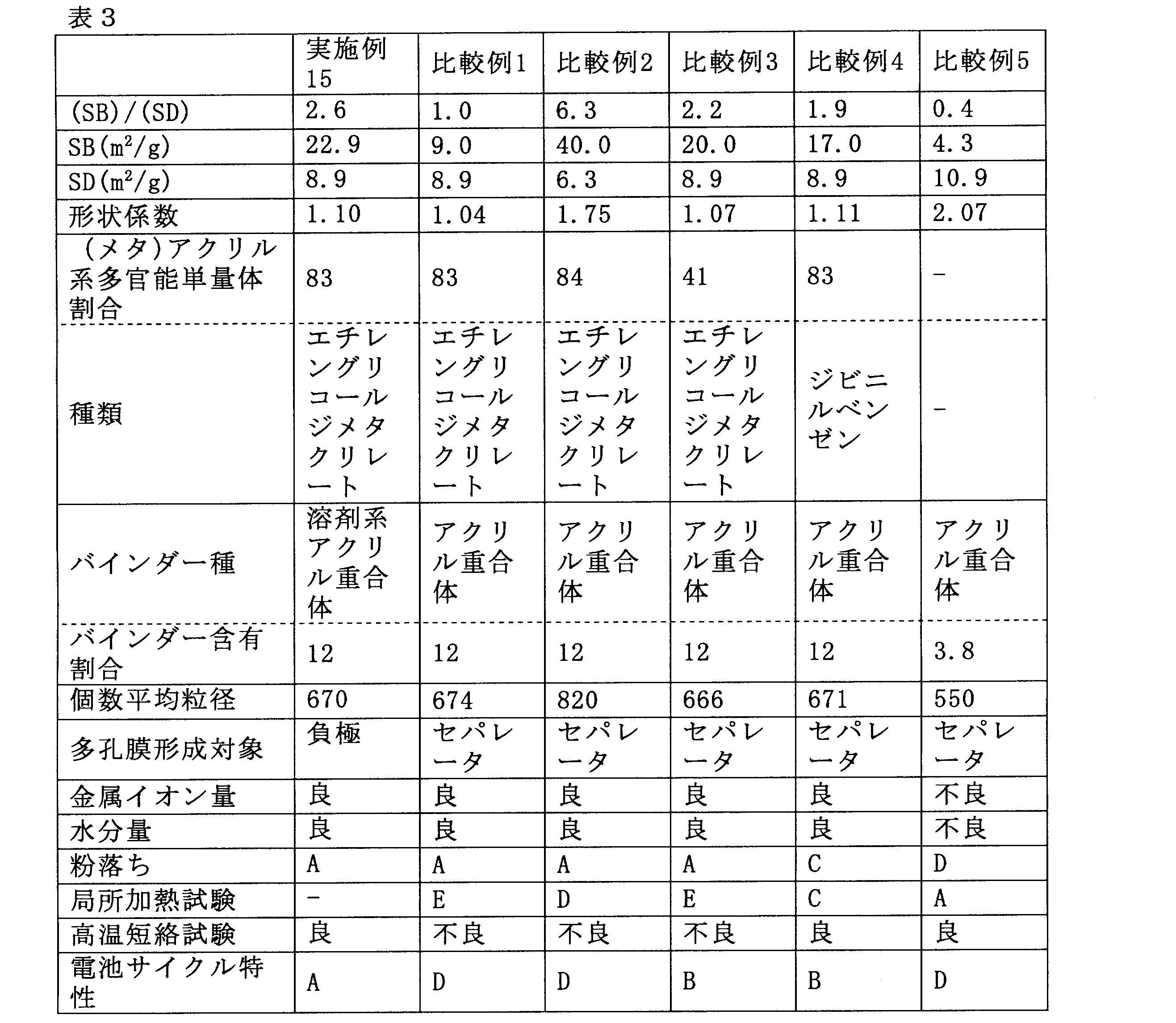
形状係数:非導電性粒子の形状係数
(メタ)アクリル系多官能単量体割合:非導電性粒子の材料の単量体全体に占める(メタ)アクリル系単量体の割合。単位は重量%。
バインダー種:多孔膜用バインダー種類。アクリル:アクリル重合体、SBR:SBR水分散体(日本ゼオン社製、製品名:BM-400B)、PVDF:ポリフッ化ビニリデン。
バインダー含有割合:多孔膜中のバインダー含有割合。単位は重量%
個数平均粒径:非導電性粒子の個数平均粒径。単位はnm。
多孔膜形成対象:多孔膜を形成した対象。セパレータ、正極又は負極。
金属イオン量:非導電性粒子の金属イオン含有量。上に述べた通り評価した結果。
水分量:多孔膜付電極または多孔膜付セパレータの水分量。上に述べた通り評価した結果。
粉落ち:多孔膜付電極または多孔膜付セパレータの粉落ち性の評価結果。
局所加熱試験:多孔膜付セパレータの耐熱性の評価結果。
高温短絡試験:多孔膜付電極または多孔膜付セパレータの信頼性試験の評価結果。
電池サイクル特性:電池のサイクル特性試験の評価結果。 The meanings of the abbreviations in the table are as follows.
Shape factor: Shape factor of non-conductive particles (Meth) acrylic polyfunctional monomer ratio: Ratio of (meth) acrylic monomer in the total amount of monomers of non-conductive particles. The unit is% by weight.
Binder type: Binder type for porous membrane. Acrylic: acrylic polymer, SBR: SBR aqueous dispersion (manufactured by Zeon Corporation, product name: BM-400B), PVDF: polyvinylidene fluoride.
Binder content ratio: Binder content ratio in the porous membrane. Unit is% by weight
Number average particle diameter: Number average particle diameter of non-conductive particles. The unit is nm.
Porous film formation target: A target on which a porous film is formed. Separator, positive electrode or negative electrode.
Metal ion content: Metal ion content of non-conductive particles. Results evaluated as described above.
Water content: Water content of the electrode with a porous film or the separator with a porous film. Results evaluated as described above.
Powder falling: Evaluation result of powder falling property of electrode with porous film or separator with porous film.
Local heating test: Evaluation result of heat resistance of separator with porous membrane.
High temperature short circuit test: Evaluation result of reliability test of electrode with porous film or separator with porous film.
Battery cycle characteristics: Evaluation results of battery cycle characteristics tests.
これに対し、非導電性粒子として、(SB)/(SD)が所定範囲外である重合体の粒子を用いた場合(比較例1及び2)及び(メタ)アクリル系多官能単量体単位の種類又は割合が所定範囲外である重合体の粒子を用いた場合(比較例3及び4)は、金属イオン量及び水分量について良好な結果が得られたが、粉落ち、局所加熱試験、高温短絡試験、電池サイクル特性の少なくとも一つにおいて不良な結果が得られた。非導電性粒子でないアルミナ粒子を用いた場合(比較例5)は、高温短絡試験について良好な結果が得られたが、金属イオン量、水分量、多孔膜均一性、粉落ち及び電池サイクル特性において、不良な結果が得られた。 As is clear from the results of Tables 1 to 3, in Examples 1 to 15 that satisfy the requirements of the present invention, good results were obtained with respect to the amount of metal ions and the amount of water, and powder falling, local heating test, high temperature In the short-circuit test and the battery cycle characteristics, good results with a good balance were obtained.
On the other hand, when the polymer particles having (SB) / (SD) outside the predetermined range are used as non-conductive particles (Comparative Examples 1 and 2) and (meth) acrylic polyfunctional monomer units When the polymer particles having a type or ratio outside the predetermined range were used (Comparative Examples 3 and 4), good results were obtained with respect to the amount of metal ions and the amount of water, but powder falling, local heating test, Poor results were obtained in at least one of the high-temperature short-circuit test and battery cycle characteristics. When alumina particles that are not non-conductive particles were used (Comparative Example 5), good results were obtained for the high-temperature short-circuit test, but in terms of metal ion content, moisture content, porous film uniformity, powder falling, and battery cycle characteristics. , Bad results were obtained.
Claims (8)
- 非導電性粒子および多孔膜用バインダーを含む二次電池用多孔膜であって、
前記非導電性粒子が、表面に凹凸を有する球状の重合体の粒子であり、
前記粒子が、下記式(1):
1.2≦(SB)/(SD)≦5.0 (1)
(式中、SBは前記粒子の実際の比表面積であり、SDは前記粒子の理論比表面積である。)を満たし、
前記粒子の形状係数の算術平均値が1.20以下であり、
前記粒子が、(メタ)アクリル系多官能単量体単位を50重量%以上含む
ことを特徴とする二次電池用多孔膜。 A porous film for a secondary battery comprising non-conductive particles and a binder for the porous film,
The non-conductive particles are spherical polymer particles having irregularities on the surface,
The particles are represented by the following formula (1):
1.2 ≦ (SB) / (SD) ≦ 5.0 (1)
Where SB is the actual specific surface area of the particles and SD is the theoretical specific surface area of the particles.
The arithmetic average value of the shape factor of the particles is 1.20 or less,
The porous film for a secondary battery, wherein the particles contain 50% by weight or more of a (meth) acrylic polyfunctional monomer unit. - 前記多孔膜用バインダーが(メタ)アクリル重合体であり、
前記二次電池用多孔膜中の前記多孔膜用バインダーの含有割合が、3~20重量%である、請求項1に記載の二次電池用多孔膜。 The porous membrane binder is a (meth) acrylic polymer,
The porous membrane for a secondary battery according to claim 1, wherein the content ratio of the binder for the porous membrane in the porous membrane for a secondary battery is 3 to 20% by weight. - 前記非導電性粒子の個数平均粒径が100~1500nmである、請求項1又は2に記載の二次電池用多孔膜。 The porous membrane for a secondary battery according to claim 1 or 2, wherein the number average particle diameter of the non-conductive particles is 100 to 1500 nm.
- 請求項1に記載の二次電池用多孔膜の製造方法であって、
重合性単量体組成物を重合して、非導電性粒子を得、
前記非導電性粒子、多孔膜用バインダー及び媒体を混合して、これらを含む多孔膜用スラリーを得、
前記多孔膜用スラリーを、基材上に塗布してスラリー層を得、
前記スラリー層を乾燥する
ことを含み、
前記非導電性粒子が、表面に凹凸を有する球状の重合体の粒子であり、
前記粒子が、下記式(1):
1.2≦(SB)/(SD)≦5.0 (1)
(式中、SBは前記粒子の実際の比表面積であり、SDは前記粒子の理論比表面積である。)を満たし、
前記粒子の形状係数の算術平均値が1.20以下であり、
前記粒子が、(メタ)アクリル系多官能単量体単位を50重量%以上含む
ことを特徴とする、製造方法。 A method for producing a porous film for a secondary battery according to claim 1,
Polymerizing the polymerizable monomer composition to obtain non-conductive particles,
Mixing the non-conductive particles, the binder for the porous membrane and the medium to obtain a slurry for the porous membrane containing these,
Applying the slurry for porous film on a substrate to obtain a slurry layer,
Drying the slurry layer,
The non-conductive particles are spherical polymer particles having irregularities on the surface,
The particles are represented by the following formula (1):
1.2 ≦ (SB) / (SD) ≦ 5.0 (1)
Where SB is the actual specific surface area of the particles and SD is the theoretical specific surface area of the particles.
The arithmetic average value of the shape factor of the particles is 1.20 or less,
The said particle | grain contains 50 weight% or more of (meth) acrylic polyfunctional monomer units. The manufacturing method characterized by the above-mentioned. - 前記多孔膜用バインダーが(メタ)アクリル重合体であり、
前記媒体が水系媒体であり、
前記多孔膜用スラリーを得る工程が、前記多孔膜用スラリーを水性分散体として得ることを含む、請求項4に記載の製造方法。 The porous membrane binder is a (meth) acrylic polymer,
The medium is an aqueous medium;
The manufacturing method according to claim 4, wherein the step of obtaining the porous membrane slurry includes obtaining the porous membrane slurry as an aqueous dispersion. - 集電体、
電極活物質及び電極合剤層用結着剤を含み、前記集電体上に付着する電極合剤層、並びに
前記電極合剤層の表面に積層された、請求項1~3のいずれか1項に記載の多孔膜を有する二次電池用電極。 Current collector,
4. An electrode mixture layer comprising an electrode active material and an electrode mixture layer binder, and deposited on the current collector, and laminated on a surface of the electrode mixture layer. An electrode for a secondary battery having the porous film according to the item. - 有機セパレータ層、及び前記有機セパレータ層上に積層された請求項1~3のいずれか1項に記載の多孔膜を有する二次電池用セパレータ。 A separator for a secondary battery having an organic separator layer and the porous film according to any one of claims 1 to 3 laminated on the organic separator layer.
- 正極、負極、セパレータ及び電解液を含む二次電池であって、前記正極、負極及びセパレータの少なくともいずれかが、請求項1~3のいずれか1項に記載の多孔膜を有する、二次電池。 A secondary battery comprising a positive electrode, a negative electrode, a separator, and an electrolyte, wherein at least one of the positive electrode, the negative electrode, and the separator has the porous film according to any one of claims 1 to 3. .
Priority Applications (5)
| Application Number | Priority Date | Filing Date | Title |
|---|---|---|---|
| EP12807867.2A EP2728646B1 (en) | 2011-07-01 | 2012-06-29 | Membrane poreuse pour batteries secondaires, procédé de sa fabrication et utilisation de celle-ci |
| KR1020137033966A KR101955247B1 (en) | 2011-07-01 | 2012-06-29 | Porous membrane for secondary batteries, method for producing same, and use of same |
| JP2013522984A JP6052174B2 (en) | 2011-07-01 | 2012-06-29 | Porous membrane for secondary battery, production method, and use |
| US14/129,472 US20140141314A1 (en) | 2011-07-01 | 2012-06-29 | Porous membrane for secondary batteries, method for producing same, and use of same |
| CN201280031413.5A CN103636027B (en) | 2011-07-01 | 2012-06-29 | Secondary cell perforated membrane, Manufacturing approach and use |
Applications Claiming Priority (2)
| Application Number | Priority Date | Filing Date | Title |
|---|---|---|---|
| JP2011147158 | 2011-07-01 | ||
| JP2011-147158 | 2011-07-01 |
Publications (1)
| Publication Number | Publication Date |
|---|---|
| WO2013005683A1 true WO2013005683A1 (en) | 2013-01-10 |
Family
ID=47437035
Family Applications (1)
| Application Number | Title | Priority Date | Filing Date |
|---|---|---|---|
| PCT/JP2012/066751 WO2013005683A1 (en) | 2011-07-01 | 2012-06-29 | Porous membrane for secondary batteries, method for producing same, and use of same |
Country Status (6)
| Country | Link |
|---|---|
| US (1) | US20140141314A1 (en) |
| EP (1) | EP2728646B1 (en) |
| JP (1) | JP6052174B2 (en) |
| KR (1) | KR101955247B1 (en) |
| CN (1) | CN103636027B (en) |
| WO (1) | WO2013005683A1 (en) |
Cited By (9)
| Publication number | Priority date | Publication date | Assignee | Title |
|---|---|---|---|---|
| WO2013180168A1 (en) * | 2012-05-30 | 2013-12-05 | 日本ゼオン株式会社 | Negative electrode for secondary batteries and method for producing same |
| JP2014040580A (en) * | 2012-07-27 | 2014-03-06 | Sumitomo Chemical Co Ltd | Production method of laminate porous film |
| JP2015005355A (en) * | 2013-06-19 | 2015-01-08 | 株式会社Gsユアサ | Power storage element |
| WO2015029939A1 (en) * | 2013-08-27 | 2015-03-05 | 日本ゼオン株式会社 | Slurry composition for porous membrane for secondary battery, secondary battery separator, secondary battery electrode, and secondary battery |
| WO2015101621A1 (en) * | 2013-12-30 | 2015-07-09 | Averis As | Process for the preparation of solid particulate vinyl aromatic polymer compositions |
| JPWO2013147006A1 (en) * | 2012-03-30 | 2015-12-14 | 日本ゼオン株式会社 | Porous membrane for secondary battery, porous membrane slurry for secondary battery, non-conductive particle, electrode for secondary battery, separator for secondary battery, and secondary battery |
| CN105658818A (en) * | 2013-10-21 | 2016-06-08 | 泰华制药工业有限公司 | Genetic markers predictive of response to glatiramer acetate |
| JP2016532996A (en) * | 2013-10-31 | 2016-10-20 | エルジー・ケム・リミテッド | Method for producing electrode-separation membrane composite, electrode-separation membrane composite produced by the production method, and lithium secondary battery including the same |
| JP2020021553A (en) * | 2018-07-30 | 2020-02-06 | 積水化学工業株式会社 | Electrode for lithium ion secondary battery and lithium ion secondary battery |
Families Citing this family (19)
| Publication number | Priority date | Publication date | Assignee | Title |
|---|---|---|---|---|
| WO2016035286A1 (en) * | 2014-09-05 | 2016-03-10 | 日本ゼオン株式会社 | Binder composition for secondary-battery electrode, slurry composition for secondary-battery electrode, secondary-battery electrode, and secondary battery |
| JP6222372B2 (en) * | 2014-09-26 | 2017-11-01 | 株式会社村田製作所 | Positive electrode for lithium ion secondary battery and lithium ion secondary battery using the same |
| KR102661503B1 (en) | 2014-12-29 | 2024-04-26 | 셀가드 엘엘씨 | Polylactam coated separator membranes for lithium ion secondary batteries and related coating formulations |
| KR20160088973A (en) | 2015-01-16 | 2016-07-27 | 더블유스코프코리아 주식회사 | Micro porous separator coated and its preparing method |
| CN106328865B (en) * | 2015-06-19 | 2019-06-11 | 宁德时代新能源科技股份有限公司 | Separator and lithium ion secondary battery |
| EP3147965B1 (en) * | 2015-09-25 | 2018-11-21 | Samsung Electronics Co., Ltd. | Composite membrane, preparing method thereof, negative electrode structure including the composite membrane, and lithium secondary battery including the negative electrode structure |
| JP7086988B2 (en) * | 2016-12-13 | 2022-06-20 | ヘンケル・アクチェンゲゼルシャフト・ウント・コムパニー・コマンディットゲゼルシャフト・アウフ・アクチェン | Improved Lithium Ion Secondary Battery and Lithium Capacitor Electrode Composition |
| WO2019026630A1 (en) * | 2017-07-31 | 2019-02-07 | パナソニックIpマネジメント株式会社 | Non-aqueous electrolyte secondary battery |
| EP3690986A4 (en) * | 2017-09-28 | 2021-04-07 | Zeon Corporation | Non-aqueous secondary battery functional layer composition, non-aqueous secondary battery functional layer, and non-aqueous secondary battery |
| KR102681543B1 (en) * | 2017-09-28 | 2024-07-03 | 니폰 제온 가부시키가이샤 | Composition for functional layer of non-aqueous secondary battery, functional layer for non-aqueous secondary battery, and non-aqueous secondary battery |
| KR102414896B1 (en) * | 2017-11-29 | 2022-07-01 | 에스케이이노베이션 주식회사 | Composite separator for secondary battery and lithium secondary battery containing the same |
| CN110364666B (en) * | 2018-04-11 | 2022-05-24 | 宁德新能源科技有限公司 | Separator and lithium ion battery |
| JP2021523527A (en) * | 2018-05-10 | 2021-09-02 | セルガード エルエルシー | Battery Separator, Coated Battery Separator, Battery and Related Methods |
| US20220140351A1 (en) * | 2019-02-26 | 2022-05-05 | Waseda University | Secondary battery negative electrode, secondary battery, and manufacturing method of secondary battery negative electrode |
| CN109980164A (en) | 2019-03-18 | 2019-07-05 | 宁德新能源科技有限公司 | Isolation film and electrochemical appliance |
| WO2021059880A1 (en) * | 2019-09-27 | 2021-04-01 | 日本ゼオン株式会社 | Slurry composition for heat-resistant layer of nonaqueous secondary battery, heat-resistant layer for nonaqueous secondary battery and nonaqueous secondary battery |
| WO2021200346A1 (en) | 2020-03-31 | 2021-10-07 | 日本ゼオン株式会社 | Organic particle dispersion for secondary cell functional layer, composition for secondary cell functional layer, cell member for secondary cell, and secondary cell |
| KR102323858B1 (en) | 2020-11-11 | 2021-11-10 | 강창기 | Manufacturing method of composite resin composition using waste separator for secondary battery |
| WO2024145895A1 (en) * | 2023-01-06 | 2024-07-11 | 宁德时代新能源科技股份有限公司 | Organic particle, separator and manufacturing method therefor, battery, and electric device |
Citations (9)
| Publication number | Priority date | Publication date | Assignee | Title |
|---|---|---|---|---|
| JP2005123115A (en) * | 2003-10-20 | 2005-05-12 | Tomoegawa Paper Co Ltd | Separator for electronic component |
| JP2005327680A (en) | 2004-05-17 | 2005-11-24 | Matsushita Electric Ind Co Ltd | Lithium ion secondary battery |
| JP2006139978A (en) | 2004-11-11 | 2006-06-01 | Hitachi Maxell Ltd | Nonaqueous battery and method for manufacturing same |
| JP2007294437A (en) | 2006-03-29 | 2007-11-08 | Hitachi Maxell Ltd | Separator for electrochemical cell, and lithium secondary battery |
| JP2008546135A (en) * | 2005-05-17 | 2008-12-18 | エルジー・ケム・リミテッド | Binder for electrochemical devices including multiple stacked electrochemical cells |
| JP2009064566A (en) | 2007-09-04 | 2009-03-26 | Hitachi Maxell Ltd | Separator for battery and nonaqueous electrolyte battery |
| WO2010074202A1 (en) * | 2008-12-26 | 2010-07-01 | 日本ゼオン株式会社 | Separator for lithium ion secondary battery, and lithium ion secondary battery |
| WO2012043729A1 (en) * | 2010-09-30 | 2012-04-05 | 日本ゼオン株式会社 | Secondary-battery porous-membrane slurry, secondary-battery porous membrane, secondary-battery electrode, secondary-battery separator, secondary battery, and method for manufacturing secondary-battery porous membrane |
| WO2012046843A1 (en) * | 2010-10-07 | 2012-04-12 | 日本ゼオン株式会社 | Slurry for secondary battery porous membrane, secondary battery porous membrane, secondary battery electrode, secondary battery separator, and secondary battery |
Family Cites Families (5)
| Publication number | Priority date | Publication date | Assignee | Title |
|---|---|---|---|---|
| DE3920129A1 (en) * | 1988-06-21 | 1989-12-28 | Ricoh Kk | ELECTROCHEMICAL DEVICE |
| EP1920920B1 (en) * | 2005-08-25 | 2013-12-04 | Toray Battery Separator Film Co., Ltd. | Polyethylene multilayer microporous membrane, battery separator using same, and battery |
| US8557437B2 (en) * | 2009-03-25 | 2013-10-15 | Tdk Corporation | Electrode comprising protective layer for lithium ion secondary battery and lithium ion secondary battery |
| WO2011040474A1 (en) * | 2009-09-30 | 2011-04-07 | 日本ゼオン株式会社 | Porous membrane for secondary battery, and secondary battery |
| EP2485295B1 (en) * | 2009-09-30 | 2019-03-20 | Zeon Corporation | Porous membrane for secondary battery, and secondary battery |
-
2012
- 2012-06-29 KR KR1020137033966A patent/KR101955247B1/en active IP Right Grant
- 2012-06-29 EP EP12807867.2A patent/EP2728646B1/en active Active
- 2012-06-29 US US14/129,472 patent/US20140141314A1/en not_active Abandoned
- 2012-06-29 JP JP2013522984A patent/JP6052174B2/en active Active
- 2012-06-29 WO PCT/JP2012/066751 patent/WO2013005683A1/en active Application Filing
- 2012-06-29 CN CN201280031413.5A patent/CN103636027B/en active Active
Patent Citations (9)
| Publication number | Priority date | Publication date | Assignee | Title |
|---|---|---|---|---|
| JP2005123115A (en) * | 2003-10-20 | 2005-05-12 | Tomoegawa Paper Co Ltd | Separator for electronic component |
| JP2005327680A (en) | 2004-05-17 | 2005-11-24 | Matsushita Electric Ind Co Ltd | Lithium ion secondary battery |
| JP2006139978A (en) | 2004-11-11 | 2006-06-01 | Hitachi Maxell Ltd | Nonaqueous battery and method for manufacturing same |
| JP2008546135A (en) * | 2005-05-17 | 2008-12-18 | エルジー・ケム・リミテッド | Binder for electrochemical devices including multiple stacked electrochemical cells |
| JP2007294437A (en) | 2006-03-29 | 2007-11-08 | Hitachi Maxell Ltd | Separator for electrochemical cell, and lithium secondary battery |
| JP2009064566A (en) | 2007-09-04 | 2009-03-26 | Hitachi Maxell Ltd | Separator for battery and nonaqueous electrolyte battery |
| WO2010074202A1 (en) * | 2008-12-26 | 2010-07-01 | 日本ゼオン株式会社 | Separator for lithium ion secondary battery, and lithium ion secondary battery |
| WO2012043729A1 (en) * | 2010-09-30 | 2012-04-05 | 日本ゼオン株式会社 | Secondary-battery porous-membrane slurry, secondary-battery porous membrane, secondary-battery electrode, secondary-battery separator, secondary battery, and method for manufacturing secondary-battery porous membrane |
| WO2012046843A1 (en) * | 2010-10-07 | 2012-04-12 | 日本ゼオン株式会社 | Slurry for secondary battery porous membrane, secondary battery porous membrane, secondary battery electrode, secondary battery separator, and secondary battery |
Non-Patent Citations (1)
| Title |
|---|
| See also references of EP2728646A4 |
Cited By (13)
| Publication number | Priority date | Publication date | Assignee | Title |
|---|---|---|---|---|
| JPWO2013147006A1 (en) * | 2012-03-30 | 2015-12-14 | 日本ゼオン株式会社 | Porous membrane for secondary battery, porous membrane slurry for secondary battery, non-conductive particle, electrode for secondary battery, separator for secondary battery, and secondary battery |
| JPWO2013180168A1 (en) * | 2012-05-30 | 2016-01-21 | 日本ゼオン株式会社 | Negative electrode for secondary battery and method for producing the same |
| WO2013180168A1 (en) * | 2012-05-30 | 2013-12-05 | 日本ゼオン株式会社 | Negative electrode for secondary batteries and method for producing same |
| US9793527B2 (en) | 2012-05-30 | 2017-10-17 | Zeon Corporation | Negative electrode for secondary batteries and method for producing same |
| JP2014040580A (en) * | 2012-07-27 | 2014-03-06 | Sumitomo Chemical Co Ltd | Production method of laminate porous film |
| JP2015005355A (en) * | 2013-06-19 | 2015-01-08 | 株式会社Gsユアサ | Power storage element |
| WO2015029939A1 (en) * | 2013-08-27 | 2015-03-05 | 日本ゼオン株式会社 | Slurry composition for porous membrane for secondary battery, secondary battery separator, secondary battery electrode, and secondary battery |
| JPWO2015029939A1 (en) * | 2013-08-27 | 2017-03-02 | 日本ゼオン株式会社 | Porous membrane slurry composition for secondary battery, separator for secondary battery, electrode for secondary battery, and secondary battery |
| CN105658818A (en) * | 2013-10-21 | 2016-06-08 | 泰华制药工业有限公司 | Genetic markers predictive of response to glatiramer acetate |
| JP2016532996A (en) * | 2013-10-31 | 2016-10-20 | エルジー・ケム・リミテッド | Method for producing electrode-separation membrane composite, electrode-separation membrane composite produced by the production method, and lithium secondary battery including the same |
| WO2015101621A1 (en) * | 2013-12-30 | 2015-07-09 | Averis As | Process for the preparation of solid particulate vinyl aromatic polymer compositions |
| US9976006B2 (en) | 2013-12-30 | 2018-05-22 | Averis As | Process for the preparation of solid particulate vinyl aromatic polymer compositions |
| JP2020021553A (en) * | 2018-07-30 | 2020-02-06 | 積水化学工業株式会社 | Electrode for lithium ion secondary battery and lithium ion secondary battery |
Also Published As
| Publication number | Publication date |
|---|---|
| CN103636027B (en) | 2015-10-21 |
| KR101955247B1 (en) | 2019-03-08 |
| JP6052174B2 (en) | 2016-12-27 |
| EP2728646A4 (en) | 2015-03-11 |
| EP2728646B1 (en) | 2016-05-18 |
| JPWO2013005683A1 (en) | 2015-02-23 |
| EP2728646A1 (en) | 2014-05-07 |
| KR20140048138A (en) | 2014-04-23 |
| US20140141314A1 (en) | 2014-05-22 |
| CN103636027A (en) | 2014-03-12 |
Similar Documents
| Publication | Publication Date | Title |
|---|---|---|
| JP6052174B2 (en) | Porous membrane for secondary battery, production method, and use | |
| JP5747918B2 (en) | Porous membrane for secondary battery, production method, and use | |
| JP5522422B2 (en) | Secondary battery porous membrane slurry, secondary battery porous membrane, secondary battery electrode, secondary battery separator and secondary battery | |
| JP5549739B2 (en) | Secondary battery porous membrane slurry, secondary battery porous membrane, secondary battery electrode, secondary battery separator and secondary battery | |
| JP5605591B2 (en) | Secondary battery porous membrane slurry, secondary battery porous membrane, secondary battery electrode, secondary battery separator, secondary battery, and method for producing secondary battery porous membrane | |
| JP6191597B2 (en) | Secondary battery separator | |
| KR101819067B1 (en) | Positive electrode for secondary batteries, method for producing same, slurry composition, and secondary battery | |
| JP5867731B2 (en) | Secondary battery porous membrane slurry, secondary battery porous membrane, secondary battery electrode, secondary battery separator, secondary battery and method for producing secondary battery porous membrane | |
| JP5516919B2 (en) | Secondary battery porous membrane, slurry for secondary battery porous membrane, and secondary battery | |
| JP5652572B2 (en) | Porous membrane for secondary battery and method for producing the same, electrode for secondary battery, separator for secondary battery, and secondary battery | |
| WO2013035795A1 (en) | Slurry for secondary batteries | |
| WO2013147006A1 (en) | Porous membrane for secondary cell, porous membrane slurry for secondary cell, nonconductive particles, electrode for secondary cell, separator for secondary cell, and secondary cell |
Legal Events
| Date | Code | Title | Description |
|---|---|---|---|
| 121 | Ep: the epo has been informed by wipo that ep was designated in this application |
Ref document number: 12807867 Country of ref document: EP Kind code of ref document: A1 |
|
| ENP | Entry into the national phase |
Ref document number: 2013522984 Country of ref document: JP Kind code of ref document: A |
|
| ENP | Entry into the national phase |
Ref document number: 20137033966 Country of ref document: KR Kind code of ref document: A |
|
| WWE | Wipo information: entry into national phase |
Ref document number: 2012807867 Country of ref document: EP |
|
| NENP | Non-entry into the national phase |
Ref country code: DE |
|
| WWE | Wipo information: entry into national phase |
Ref document number: 14129472 Country of ref document: US |