WO2013002020A1 - Air intake device for internal combustion engine - Google Patents
Air intake device for internal combustion engine Download PDFInfo
- Publication number
- WO2013002020A1 WO2013002020A1 PCT/JP2012/065031 JP2012065031W WO2013002020A1 WO 2013002020 A1 WO2013002020 A1 WO 2013002020A1 JP 2012065031 W JP2012065031 W JP 2012065031W WO 2013002020 A1 WO2013002020 A1 WO 2013002020A1
- Authority
- WO
- WIPO (PCT)
- Prior art keywords
- exhaust gas
- flow path
- intake
- gas flow
- upstream
- Prior art date
Links
Images

Classifications
-
- F—MECHANICAL ENGINEERING; LIGHTING; HEATING; WEAPONS; BLASTING
- F02—COMBUSTION ENGINES; HOT-GAS OR COMBUSTION-PRODUCT ENGINE PLANTS
- F02M—SUPPLYING COMBUSTION ENGINES IN GENERAL WITH COMBUSTIBLE MIXTURES OR CONSTITUENTS THEREOF
- F02M35/00—Combustion-air cleaners, air intakes, intake silencers, or induction systems specially adapted for, or arranged on, internal-combustion engines
- F02M35/10—Air intakes; Induction systems
- F02M35/104—Intake manifolds
-
- F—MECHANICAL ENGINEERING; LIGHTING; HEATING; WEAPONS; BLASTING
- F02—COMBUSTION ENGINES; HOT-GAS OR COMBUSTION-PRODUCT ENGINE PLANTS
- F02M—SUPPLYING COMBUSTION ENGINES IN GENERAL WITH COMBUSTIBLE MIXTURES OR CONSTITUENTS THEREOF
- F02M35/00—Combustion-air cleaners, air intakes, intake silencers, or induction systems specially adapted for, or arranged on, internal-combustion engines
- F02M35/10—Air intakes; Induction systems
- F02M35/10209—Fluid connections to the air intake system; their arrangement of pipes, valves or the like
- F02M35/10222—Exhaust gas recirculation [EGR]; Positive crankcase ventilation [PCV]; Additional air admission, lubricant or fuel vapour admission
-
- F—MECHANICAL ENGINEERING; LIGHTING; HEATING; WEAPONS; BLASTING
- F02—COMBUSTION ENGINES; HOT-GAS OR COMBUSTION-PRODUCT ENGINE PLANTS
- F02M—SUPPLYING COMBUSTION ENGINES IN GENERAL WITH COMBUSTIBLE MIXTURES OR CONSTITUENTS THEREOF
- F02M35/00—Combustion-air cleaners, air intakes, intake silencers, or induction systems specially adapted for, or arranged on, internal-combustion engines
- F02M35/10—Air intakes; Induction systems
- F02M35/10242—Devices or means connected to or integrated into air intakes; Air intakes combined with other engine or vehicle parts
- F02M35/10268—Heating, cooling or thermal insulating means
-
- F—MECHANICAL ENGINEERING; LIGHTING; HEATING; WEAPONS; BLASTING
- F02—COMBUSTION ENGINES; HOT-GAS OR COMBUSTION-PRODUCT ENGINE PLANTS
- F02M—SUPPLYING COMBUSTION ENGINES IN GENERAL WITH COMBUSTIBLE MIXTURES OR CONSTITUENTS THEREOF
- F02M35/00—Combustion-air cleaners, air intakes, intake silencers, or induction systems specially adapted for, or arranged on, internal-combustion engines
- F02M35/10—Air intakes; Induction systems
- F02M35/10314—Materials for intake systems
- F02M35/10321—Plastics; Composites; Rubbers
Definitions
- the present invention relates to an intake system for an internal combustion engine having an intake flow path for supplying air from a surge tank to a combustion chamber of an internal combustion engine and an exhaust gas flow path for supplying exhaust gas from an exhaust gas distribution header to the combustion chamber.
- the intake system for an internal combustion engine is an intake system for mixing exhaust gas or blowby gas generated by driving the internal combustion engine as exhaust gas, or evaporation gas (evaporative gas of fuel) with air for combustion and burning it in a combustion chamber. It has a flow path and an exhaust gas flow path.
- a first exhaust gas flow path for supplying exhaust gas as exhaust gas from an EGR surge tank as an exhaust gas distribution header to a combustion chamber, and blow-by gas as exhaust gas from inside a cylinder head cover as an exhaust gas distribution header There is disclosed a conventional intake system for an internal combustion engine having a second exhaust gas flow path for supplying to the combustion chamber and a third exhaust gas flow path for supplying evaporation gas as exhaust gas to the combustion chamber from an exhaust gas distribution header (not shown).
- the respective downstream side exhaust gas flow path portions of the first to third exhaust gas flow paths are constituted by a common flow path common to the downstream side intake flow path portion of the intake flow path.
- Each of the upstream exhaust gas flow passage portions upstream of the common flow passage among the first to third exhaust gas flow passages is appropriately disposed in accordance with the position of the EGR surge tank, the cylinder head cover, and the like. That is, the relationship between the exhaust gas flow path length along the flow path center line of each exhaust gas flow path and the intake flow path length along the flow path central line of the intake flow path is not taken into consideration. The length is set appropriately according to the position of the EGR surge tank, the cylinder head cover, and the like.
- the inertia supercharging effect is impaired, the amount of intake air to the combustion chamber is likely to be reduced, and the engine output may be reduced. That is, when the pulsation timing of the air in the intake passage and the pulsation timing of the exhaust gas in the exhaust gas passage deviate from each other, the pressure wave in which the air in the intake passage becomes dense and the pressure wave in which the exhaust gas in the exhaust passage becomes sparse As they overlap with each other, the intake pressure tends to decrease, and as a result, the amount of intake air tends to decrease.
- the present invention has been made in view of the above-described circumstances, and an object of the present invention is to provide an intake system for an internal combustion engine capable of appropriately maintaining the amount of intake of air into the combustion chamber.
- an intake air flow path for supplying air from a surge tank to a combustion chamber of the internal combustion engine and an exhaust gas flow path for supplying exhaust gas from an exhaust gas distribution header to the combustion chamber
- the exhaust gas flow path length along the flow path center line of the exhaust gas flow path is set to 75% or more and 125% or less of the intake flow path length along the flow path center line of the intake flow path. It is on the point.
- the exhaust gas flow path length along the flow path center line of the exhaust gas flow path is 75% or more and 125% or less of the intake flow path length along the flow path center line of the intake flow path. It is set to. For this reason, it is difficult for the pulsation timing of air in the intake passage to deviate from the pulsation timing of the exhaust gas in the exhaust passage, and the pressure wave in which the air in the intake passage becomes dense and the pressure wave in which the exhaust gas in the exhaust passage becomes dense. It is easy to put Therefore, in the case of the intake system for an internal combustion engine of this configuration, it is possible to appropriately maintain the amount of intake of air into the combustion chamber and to suppress the decrease in the amount of intake air.
- the intake passage is constituted by the upstream intake passage portion and the downstream intake passage portion, and the exhaust gas passage is formed by the upstream exhaust gas passage portion and the downstream side
- the exhaust gas flow path portion and the downstream side exhaust gas flow path portion and the downstream side intake flow path portion are common flow paths, and the exhaust gas flow path length and the intake flow path length are the same. It is on the point.
- the exhaust gas and the air for combustion can be mixed in the common flow path and supplied to the combustion chamber.
- the exhaust gas flow path length along the flow path center line of the exhaust gas flow path is set to be the same as the intake flow path length along the flow path center line of the intake flow path. Therefore, it is possible to substantially match the pulsation timing of the air in the intake passage and the pulsation timing of the exhaust gas in the exhaust passage. Therefore, the effect of suppressing the decrease in the amount of intake air can be enhanced by appropriately maintaining the amount of intake of air into the combustion chamber.
- a third characterizing feature of the present invention is that the ratio Lc / D of the upstream exhaust gas flow path length Lc to the flow path diameter D along the flow path center line of the upstream exhaust gas flow path portion is set to 3 or more. is there.
- the ratio Lc / D of the upstream exhaust gas channel length Lc to the channel diameter D is set to 3 or more, so the upstream exhaust gas channel part merges into the intake air channel (common channel)
- the flow of exhaust gas can be reliably formed, and the flow of the mixture of exhaust gas and combustion air can be stabilized.
- the upstream exhaust gas flow passage and the upstream intake air flow passage upstream of the common flow passage in the intake air flow passage are arranged in parallel to one another. It is on the point.
- the exhaust gas flow path length can be easily set to a predetermined ratio of the intake flow path length.
- the upstream exhaust gas flow path portion and the common flow path are formed, and the flow path center line of the upstream exhaust gas flow path portion is relative to the flow path central line of the intake flow path. They are connected to one another so that they cross at an angle of 90 ° or less.
- a sixth characterizing feature of the present invention lies in that the upstream exhaust gas flow passage portion and the upstream intake air flow passage portion are sectioned by a common flow passage wall and arranged in parallel.
- the upstream side exhaust gas flow passage portion and the upstream side intake air flow passage portion can be disposed compactly.
- the exhaust gas is an exhaust gas or a blowby gas
- the heat of the exhaust gas is conducted to the air of the upstream intake flow passage portion through the common flow passage wall to preheat the combustion air. it can.
- a seventh characterizing feature of the present invention is that the upstream side exhaust gas flow path portion is connected in communication with the middle of the intake air flow path.
- the eighth characterizing feature of the present invention is that the upstream exhaust gas flow passage portion and the exhaust gas distribution header are formed by a body forming the exhaust gas flow passage and a body forming the surge tank.
- the upstream side exhaust gas flow passage portion and the exhaust gas distribution header can be easily disposed.
- FIG. 1 is a longitudinal sectional view showing an intake system for an internal combustion engine.
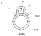
- FIG. 2 is a cross-sectional view taken along line II-II of FIG.
- FIG. 1 shows an intake system B for an internal combustion engine according to the present invention equipped in a gasoline engine (an example of an internal combustion engine) A provided with a plurality of cylinders 1.
- the engine A includes a metal cylinder block 2 in which a plurality of cylinders 1 are formed, and a metal cylinder head 3 connected to an upper portion of the cylinder block 2.
- a resin intake manifold 5 communicated with the resin surge tank 4 is connected to the cylinder head 3.
- a combustion chamber 7 is formed between the cylinder head 3 and the piston 6 installed in each cylinder 1. In FIG. 1, only a portion corresponding to one cylinder 1 is shown.
- the cylinder head 3 includes a plurality of cylinder-side intake passages 8 communicating with the combustion chambers 7, a plurality of intake valves 9 opening and closing the outlet side of the cylinder-side intake passages 8, and a plurality communicating with the combustion chambers 7. And a plurality of exhaust valves 11 for opening and closing the inlet side of each exhaust flow passage 10.
- a plurality of circular cross sections from the surge tank 4 to the combustion chamber 7 are provided over the entire length.
- the combustion chamber from the exhaust gas distribution header 13 The cross-sectional shape up to 7 has a plurality of circular exhaust gas channels 14 over the entire length.
- Intake manifold 5 includes a plurality of intake manifold side intake flow paths (hereinafter referred to as "in-manifold side intake flow paths") 15 communicatively connected to each cylinder side intake flow path 8 and air provided in each intake side intake flow path 15.
- a flow control valve (butterfly valve) 16 is provided. Therefore, the intake system B for the internal combustion engine has the intake flow passage 12 formed in series by the intake manifold side intake flow passage 15 and the cylinder side intake flow passage 8.
- the exhaust gas flow path 14 includes an upstream exhaust gas flow path portion 17 communicating from the upper side at an intermediate position downstream of the air flow control valve 16 in the intake manifold side intake flow path 15, and a downstream exhaust gas flow downstream thereof.
- the upstream exhaust gas passage portion 17 is connected to a midway point of the intake passage 12 and has a passage portion 18.
- the downstream side exhaust gas flow passage portion 18 and the downstream side intake air flow passage portion 19 downstream of the portion of the intake air flow passage 12 where the upstream side exhaust gas flow passage portion 17 communicates are constituted by the common flow passage 20 ing.
- the upstream exhaust gas passage portion 17 is formed of a portion on the upstream side of the common flow passage 20 in the exhaust gas flow passage 14, and the upstream intake air flow passage portion 21 is a common flow of the intake flow passage 12.
- An upstream side of the passage 20 is configured.
- Intake manifold 5 and surge tank 4 are made of resin integrally including connection flange 22 for cylinder head 3, lower intake passage wall portion 23 having a half shape, and lower surge tank wall portion 24 having a half shape.
- the lower body 25 and the upper resin body 28 integrally provided with the upper intake flow passage wall portion 26 having the half shape and the upper surge tank wall portion 27 having the half shape are mutually joined by, for example, vibration welding or the like. It is configured.
- the upstream exhaust gas flow passage portion 17 and the exhaust gas distribution header 13 are provided with a resin exhaust gas flow passage forming body 29 joined by vibration welding or the like on the upper surface side of the upper body 28 to form the upper body 28 and the exhaust gas flow passage forming body. It is formed between 29.
- the flow passage center line (Y-Y2) of the upstream exhaust gas flow passage portion 17 is relative to the flow passage central line (XZ) of the intake flow passage 12 They are connected to each other so as to intersect at an angle ⁇ of 90 ° or less.
- X is the center of the intake flow passage 12 at the boundary between the surge tank 4 and the upstream intake flow passage portion 21, which is the start point of the intake flow passage 12.
- Z is the center of the intake flow passage 12 at the boundary between the combustion chamber 7 and the downstream side intake flow passage portion 19 which is the end point of the intake flow passage 12.
- Y as the start point of the exhaust gas flow passage 14 is the center of the exhaust gas flow passage 14 at the boundary between the exhaust gas distribution header 13 and the upstream exhaust gas flow passage portion 17, and the end point is the end point as the intake flow passage 12 It is the same Z.
- Y 2 is a point where the extension line of the flow path center line of the upstream side exhaust gas flow path portion 17 intersects the flow path center line (XZ) of the intake flow path 12.
- a total length of La) is set to 75% or more and 125% or less of the intake passage length Lb along the passage center line (XZ) of the intake passage 12.
- the exhaust gas flow path length La is set to substantially the same length (approximately 100%) as the intake flow path length Lb (420 mm).
- Y1 is a point where the flow passage center line of the upstream exhaust gas flow passage portion 17 intersects with the outlet opening to the intake flow passage 12 of the upstream exhaust gas flow passage portion 17.
- X1 is a point where a line segment passing through Y1 intersects the flow passage center line (XZ) of the intake flow passage 12 at a right angle.
- the intake system for an internal combustion engine according to the present invention may have the intake flow passage and the exhaust gas flow passage separately over the entire length. 2.
- the intake system for an internal combustion engine according to the present invention may have an exhaust gas flow path for supplying blow-by gas as exhaust gas to the combustion chamber. 3.
- the intake system for an internal combustion engine according to the present invention may have an exhaust gas flow path for supplying the evaporation gas as the exhaust gas to the combustion chamber. 4.
- the upstream side exhaust gas flow passage portion may be formed independently of piping that is different from the piping that forms the upstream side intake flow passage portion. 5.
- the intake system for an internal combustion engine according to the present invention may be equipped with a rotary engine in addition to a reciprocating engine such as a gasoline engine or a diesel engine.
Landscapes
- Engineering & Computer Science (AREA)
- Chemical & Material Sciences (AREA)
- Combustion & Propulsion (AREA)
- Mechanical Engineering (AREA)
- General Engineering & Computer Science (AREA)
- Exhaust-Gas Circulating Devices (AREA)
- Cylinder Crankcases Of Internal Combustion Engines (AREA)
Abstract
Description
特許文献1には、排ガスとしての排気ガスを排ガス分配ヘッダとしてのEGRサージタンクから燃焼室に供給する第1排ガス流路と、排ガスとしてのブローバイガスを排ガス分配ヘッダとしてのシリンダヘッドカバー内部から燃焼室に供給する第2排ガス流路と、排ガスとしてのエバポガスを図示しない排ガス分配ヘッダから燃焼室に供給する第3排ガス流路とを有する従来の内燃機関用吸気装置が開示されている。
第1~第3排ガス流路の夫々の下流側排ガス流路部分は、吸気流路の下流側吸気流路部分と共通の共通流路で構成してある。
第1~第3排ガス流路のうちの共通流路よりも上流側の上流側排ガス流路部分の夫々は、EGRサージタンクやシリンダヘッドカバーなどの位置に応じて適宜に配設されている。
すなわち、各排ガス流路の流路中心線に沿う排ガス流路長と、吸気流路の流路中心線に沿う吸気流路長との関係は考慮されておらず、各排ガス流路長は、EGRサージタンクやシリンダヘッドカバーなどの位置に応じた適宜の長さに設定されている。 The intake system for an internal combustion engine is an intake system for mixing exhaust gas or blowby gas generated by driving the internal combustion engine as exhaust gas, or evaporation gas (evaporative gas of fuel) with air for combustion and burning it in a combustion chamber. It has a flow path and an exhaust gas flow path.
In Patent Document 1, a first exhaust gas flow path for supplying exhaust gas as exhaust gas from an EGR surge tank as an exhaust gas distribution header to a combustion chamber, and blow-by gas as exhaust gas from inside a cylinder head cover as an exhaust gas distribution header There is disclosed a conventional intake system for an internal combustion engine having a second exhaust gas flow path for supplying to the combustion chamber and a third exhaust gas flow path for supplying evaporation gas as exhaust gas to the combustion chamber from an exhaust gas distribution header (not shown).
The respective downstream side exhaust gas flow path portions of the first to third exhaust gas flow paths are constituted by a common flow path common to the downstream side intake flow path portion of the intake flow path.
Each of the upstream exhaust gas flow passage portions upstream of the common flow passage among the first to third exhaust gas flow passages is appropriately disposed in accordance with the position of the EGR surge tank, the cylinder head cover, and the like.
That is, the relationship between the exhaust gas flow path length along the flow path center line of each exhaust gas flow path and the intake flow path length along the flow path central line of the intake flow path is not taken into consideration. The length is set appropriately according to the position of the EGR surge tank, the cylinder head cover, and the like.
つまり、吸気流路における空気の脈動タイミングと排ガス流路における排ガスの脈動タイミングとが互いにずれると、吸気流路における空気が密になる圧力波と排ガス流路における排ガスが疎になる圧力波とが互いに重なって吸気圧力が低下し易く、その結果、吸入空気量が低下し易い。
本発明は上記実情に鑑みてなされたものであって、燃焼室への空気の吸入量を適切に維持することができる内燃機関用吸気装置を提供することを目的とする。 For this reason, the inertia supercharging effect is impaired, the amount of intake air to the combustion chamber is likely to be reduced, and the engine output may be reduced.
That is, when the pulsation timing of the air in the intake passage and the pulsation timing of the exhaust gas in the exhaust gas passage deviate from each other, the pressure wave in which the air in the intake passage becomes dense and the pressure wave in which the exhaust gas in the exhaust passage becomes sparse As they overlap with each other, the intake pressure tends to decrease, and as a result, the amount of intake air tends to decrease.
The present invention has been made in view of the above-described circumstances, and an object of the present invention is to provide an intake system for an internal combustion engine capable of appropriately maintaining the amount of intake of air into the combustion chamber.
このため、吸気流路における空気の脈動タイミングと、排ガス流路における排ガスの脈動タイミングとがずれにくくなり、吸気流路における空気が密になる圧力波と排ガス流路における排ガスが密になる圧力波とを重ね易い。
したがって、本構成の内燃機関用吸気装置であれば、燃焼室への空気の吸入量を適切に維持して吸入空気量の低下を抑制することができる。 In the intake system for an internal combustion engine of this configuration, the exhaust gas flow path length along the flow path center line of the exhaust gas flow path is 75% or more and 125% or less of the intake flow path length along the flow path center line of the intake flow path. It is set to.
For this reason, it is difficult for the pulsation timing of air in the intake passage to deviate from the pulsation timing of the exhaust gas in the exhaust passage, and the pressure wave in which the air in the intake passage becomes dense and the pressure wave in which the exhaust gas in the exhaust passage becomes dense. It is easy to put
Therefore, in the case of the intake system for an internal combustion engine of this configuration, it is possible to appropriately maintain the amount of intake of air into the combustion chamber and to suppress the decrease in the amount of intake air.
また、排ガス流路の流路中心線に沿う排ガス流路長を、吸気流路の流路中心線に沿う吸気流路長と同じに設定してある。
このため、吸気流路における空気の脈動タイミングと、排ガス流路における排ガスの脈動タイミングとをほぼ一致させることができる。
したがって、燃焼室への空気の吸入量を適切に維持して吸入空気量の低下を抑制する効果を高めることができる。 With this configuration, the exhaust gas and the air for combustion can be mixed in the common flow path and supplied to the combustion chamber.
Further, the exhaust gas flow path length along the flow path center line of the exhaust gas flow path is set to be the same as the intake flow path length along the flow path center line of the intake flow path.
Therefore, it is possible to substantially match the pulsation timing of the air in the intake passage and the pulsation timing of the exhaust gas in the exhaust passage.
Therefore, the effect of suppressing the decrease in the amount of intake air can be enhanced by appropriately maintaining the amount of intake of air into the combustion chamber.
また、排ガスが排気ガスやブローバイガスである場合に、その排ガスが有する熱を共通の流路壁を介して上流側吸気流路部分の空気に伝導させて、燃焼用の空気を予熱することができる。 With this configuration, the upstream side exhaust gas flow passage portion and the upstream side intake air flow passage portion can be disposed compactly.
In addition, when the exhaust gas is an exhaust gas or a blowby gas, the heat of the exhaust gas is conducted to the air of the upstream intake flow passage portion through the common flow passage wall to preheat the combustion air. it can.
図1は、複数のシリンダ1を備えたガソリンエンジン(内燃機関の一例)Aに装備された本発明による内燃機関用吸気装置Bを示す。 Embodiments of the present invention will be described below based on the drawings.
FIG. 1 shows an intake system B for an internal combustion engine according to the present invention equipped in a gasoline engine (an example of an internal combustion engine) A provided with a plurality of cylinders 1.
シリンダヘッド3には、樹脂製サージタンク4に連通された樹脂製インテークマニホールド5が連結されている。シリンダヘッド3と各シリンダ1に内装されたピストン6との間に燃焼室7が形成されている。
尚、図1では、一つのシリンダ1に対応する部分のみを示している。 The engine A includes a metal cylinder block 2 in which a plurality of cylinders 1 are formed, and a
A
In FIG. 1, only a portion corresponding to one cylinder 1 is shown.
したがって、内燃機関用吸気装置Bは、インマニ側吸気流路15とシリンダ側吸気流路8とによって一連に形成された吸気流路12を有している。
Therefore, the intake system B for the internal combustion engine has the
また、上流側排ガス流路部分17は、排ガス流路14のうちの共通流路20よりも上流側の部分で構成され、上流側吸気流路部分21は、吸気流路12のうちの共通流路20よりも上流側の部分で構成されている。 Therefore, the downstream side exhaust gas
Further, the upstream exhaust
Xは、吸気流路12としての始点となる、サージタンク4と上流側吸気流路部分21との境界における吸気流路12の中心である。
Zは、吸気流路12としての終点となる、燃焼室7と下流側吸気流路部分19との境界における吸気流路12の中心である。
一方、排ガス流路14としての始点となるYは、排ガス分配ヘッダ13と上流側排ガス流路部分17との境界における排ガス流路14の中心であり、終点は、吸気流路12としての終点と同じZである。
Y2は、上流側排ガス流路部分17の流路中心線の延長線が、吸気流路12の流路中心線(X-Z)と交わる箇所である。 In the upstream exhaust
X is the center of the
Z is the center of the
On the other hand, Y as the start point of the exhaust
Y 2 is a point where the extension line of the flow path center line of the upstream side exhaust gas
Y1は、上流側排ガス流路部分17の流路中心線が、当該上流側排ガス流路部分17の吸気流路12への出口開口と交差する箇所である。
X1は、Y1を通る線分が吸気流路12の流路中心線(X-Z)と直角に交わる箇所である。 As shown in FIG. 1, the exhaust gas flow path length (Y-Y1 and X1-Z) along the flow path center line (Y-Y1 and X1-Z) of the exhaust
Y1 is a point where the flow passage center line of the upstream exhaust gas
X1 is a point where a line segment passing through Y1 intersects the flow passage center line (XZ) of the
1.本発明による内燃機関用吸気装置は、吸気流路と排ガス流路とを全長に亘って各別に有していてもよい。
2.本発明による内燃機関用吸気装置は、排ガスとしてのブローバイガスを燃焼室に供給する排ガス流路を有していてもよい。
3.本発明による内燃機関用吸気装置は、排ガスとしてのエバポガスを燃焼室に供給する排ガス流路を有していてもよい。
4.本発明による内燃機関用吸気装置は、上流側排ガス流路部分が、上流側吸気流路部分を形成する配管とは別の配管で独立に形成されていてもよい。
5.本発明による内燃機関用吸気装置は、ガソリンエンジンやディーゼルエンジンなどのレシプロエンジンの他に、ロータリーエンジンに装備されるものであってもよい。 Other Embodiments
1. The intake system for an internal combustion engine according to the present invention may have the intake flow passage and the exhaust gas flow passage separately over the entire length.
2. The intake system for an internal combustion engine according to the present invention may have an exhaust gas flow path for supplying blow-by gas as exhaust gas to the combustion chamber.
3. The intake system for an internal combustion engine according to the present invention may have an exhaust gas flow path for supplying the evaporation gas as the exhaust gas to the combustion chamber.
4. In the intake system for an internal combustion engine according to the present invention, the upstream side exhaust gas flow passage portion may be formed independently of piping that is different from the piping that forms the upstream side intake flow passage portion.
5. The intake system for an internal combustion engine according to the present invention may be equipped with a rotary engine in addition to a reciprocating engine such as a gasoline engine or a diesel engine.
7 燃焼室
12 吸気流路
13 排ガス分配ヘッダ
14 排ガス流路
17 上流側排ガス流路部分
18 下流側排ガス流路部分
19 下流側吸気流路部分
20 共通流路
21 上流側吸気流路部分
30 共通の流路壁
A 内燃機関
D 流路径
La 排ガス流路長
Lb 吸気流路長
Lc 上流側排ガス流路長
X-Z 吸気流路の流路中心線
Y-Y1,X1-Z 排ガス流路の流路中心線
Y-Y1 上流側排ガス流路部分の流路中心線
θ 角度 4 surge tank 7
Claims (8)
- サージタンクから内燃機関の燃焼室に空気を供給する吸気流路と、
排ガス分配ヘッダから前記燃焼室に排ガスを供給する排ガス流路とを有し、
前記排ガス流路の流路中心線に沿う排ガス流路長を、前記吸気流路の流路中心線に沿う吸気流路長の75%以上、かつ、125%以下に設定してある内燃機関用吸気装置。 An intake passage for supplying air from the surge tank to the combustion chamber of the internal combustion engine;
And an exhaust gas flow path for supplying exhaust gas from the exhaust gas distribution header to the combustion chamber;
For an internal combustion engine in which the exhaust gas flow path length along the flow path center line of the exhaust gas flow path is set to 75% or more and 125% or less of the intake flow path length along the flow path center line of the intake flow path Inspiratory device. - 前記吸気流路は、上流側吸気流路部分と下流側吸気流路部分とで構成されると共に、
前記排ガス流路は、上流側排ガス流路部分と下流側排ガス流路部分とで構成されており、
前記下流側排ガス流路部分と前記下流側吸気流路部分とを共通流路にして、
前記排ガス流路長と前記吸気流路長とが同じである請求項1記載の内燃機関用吸気装置。 The intake passage is constituted by an upstream intake passage portion and a downstream intake passage portion, and
The exhaust gas flow path is composed of an upstream side exhaust gas flow path portion and a downstream side exhaust gas flow path portion,
With the downstream side exhaust gas flow passage portion and the downstream side intake air flow passage portion as common flow passages,
The intake system for the internal combustion engine according to claim 1, wherein the exhaust gas flow path length and the intake flow path length are the same. - 前記上流側排ガス流路部分の流路中心線に沿う上流側排ガス流路長Lcと流路径Dとの比Lc/Dを3以上に設定してある請求項2に記載の内燃機関用吸気装置。 The intake system according to claim 2, wherein a ratio Lc / D of the upstream exhaust gas flow path length Lc along the flow path center line of the upstream exhaust gas flow path portion to the flow path diameter D is set to 3 or more. .
- 前記上流側排ガス流路部分と、前記上流側吸気流路部分とを互いに平行に並設してある請求項2又は3に記載の内燃機関用吸気装置。 The intake system for an internal combustion engine according to claim 2 or 3, wherein the upstream exhaust gas flow passage portion and the upstream intake air flow passage portion are arranged in parallel in parallel with each other.
- 前記上流側排ガス流路部分と前記共通流路とを、前記上流側排ガス流路部分の流路中心線が、前記吸気流路の流路中心線に対して90°以下の角度で交差するように互いに接続してある請求項2から請求項4のいずれか一項に記載の内燃機関用吸気装置。 The flow path center line of the upstream exhaust gas flow path portion intersects the flow path center line of the intake flow path at an angle of 90 ° or less with the upstream exhaust gas flow path portion and the common flow path. An intake system for an internal combustion engine according to any one of claims 2 to 4, connected to each other.
- 前記上流側排ガス流路部分と前記上流側吸気流路部分とを、共通の流路壁で区画して並設してある請求項4に記載の内燃機関用吸気装置。 5. The intake system for an internal combustion engine according to claim 4, wherein the upstream exhaust gas flow passage portion and the upstream intake air flow passage portion are arranged in parallel by dividing a common flow passage wall.
- 前記上流側排ガス流路部分を、前記吸気流路の途中に連通接続してある請求項2から請求項6のいずれか一項に記載の内燃機関用吸気装置。 The intake system for an internal combustion engine according to any one of claims 2 to 6, wherein the upstream side exhaust gas flow passage portion is communicatively connected in the middle of the intake air flow passage.
- 前記上流側排ガス流路部分と前記排ガス分配ヘッダとが、前記排ガス流路を形成するボディと前記サージタンクを形成するボディとにより形成されている請求項2から請求項7のいずれか一項に記載の内燃機関用吸気装置。
The upstream side exhaust gas flow passage portion and the exhaust gas distribution header are formed by a body forming the exhaust gas flow passage and a body forming the surge tank. An intake system for an internal combustion engine as described above.
Priority Applications (2)
| Application Number | Priority Date | Filing Date | Title |
|---|---|---|---|
| CN201290000601.7U CN203655472U (en) | 2011-06-28 | 2012-06-12 | Gas-inlet apparatus for internal combustion engine |
| US14/114,596 US9273652B2 (en) | 2011-06-28 | 2012-06-12 | Air intake device for internal combustion engine |
Applications Claiming Priority (2)
| Application Number | Priority Date | Filing Date | Title |
|---|---|---|---|
| JP2011-142915 | 2011-06-28 | ||
| JP2011142915A JP2013011185A (en) | 2011-06-28 | 2011-06-28 | Air intake device for internal combustion engine |
Publications (1)
| Publication Number | Publication Date |
|---|---|
| WO2013002020A1 true WO2013002020A1 (en) | 2013-01-03 |
Family
ID=47423919
Family Applications (1)
| Application Number | Title | Priority Date | Filing Date |
|---|---|---|---|
| PCT/JP2012/065031 WO2013002020A1 (en) | 2011-06-28 | 2012-06-12 | Air intake device for internal combustion engine |
Country Status (4)
| Country | Link |
|---|---|
| US (1) | US9273652B2 (en) |
| JP (1) | JP2013011185A (en) |
| CN (1) | CN203655472U (en) |
| WO (1) | WO2013002020A1 (en) |
Cited By (1)
| Publication number | Priority date | Publication date | Assignee | Title |
|---|---|---|---|---|
| JP2018071524A (en) * | 2016-11-04 | 2018-05-10 | マツダ株式会社 | Air-intake system of engine with egr device |
Families Citing this family (10)
| Publication number | Priority date | Publication date | Assignee | Title |
|---|---|---|---|---|
| CN104265523B (en) * | 2014-09-29 | 2017-01-11 | 日立汽车系统(苏州)有限公司 | Intake manifold pressure stabilizer and engine system comprising same |
| JP6295929B2 (en) * | 2014-11-25 | 2018-03-20 | アイシン精機株式会社 | Intake device for internal combustion engine |
| DE102015005372B4 (en) * | 2015-04-28 | 2016-12-08 | Mann + Hummel Gmbh | Air distributor for an internal combustion engine |
| JP2018025123A (en) * | 2016-08-09 | 2018-02-15 | アイシン精機株式会社 | Intake device |
| JP6698513B2 (en) * | 2016-12-21 | 2020-05-27 | 愛三工業株式会社 | Engine system and intake manifold used therefor |
| FR3077092B1 (en) * | 2018-01-24 | 2020-01-10 | Renault S.A.S. | OPTIMIZED AIR INTAKE CIRCUIT OF A VEHICLE DRIVE GROUP |
| FR3081936B1 (en) * | 2018-06-05 | 2020-12-18 | Psa Automobiles Sa | AUTOMOTIVE VEHICLE ENGINE KIT WITH INTEGRATED CANISTER PURGE HOSE |
| JP7358824B2 (en) * | 2019-08-01 | 2023-10-11 | マツダ株式会社 | engine intake system |
| JP7553386B2 (en) | 2021-03-17 | 2024-09-18 | ダイハツ工業株式会社 | Engine intake manifold |
| JPWO2023062772A1 (en) * | 2021-10-14 | 2023-04-20 |
Citations (6)
| Publication number | Priority date | Publication date | Assignee | Title |
|---|---|---|---|---|
| JPH02115523A (en) * | 1988-10-26 | 1990-04-27 | Mazda Motor Corp | Air intake device of engine |
| JP2001207918A (en) * | 2000-01-26 | 2001-08-03 | Daihatsu Motor Co Ltd | Exhaust gas circulating device to air intake manifold in internal combustion engine |
| JP2004270538A (en) * | 2003-03-07 | 2004-09-30 | Mitsubishi Motors Corp | Gas circulation device of internal combustion engine |
| JP2009209855A (en) * | 2008-03-05 | 2009-09-17 | Toyota Motor Corp | Gas introduction structure of intake passage and intake manifold |
| JP2010521619A (en) * | 2007-03-23 | 2010-06-24 | ベール ゲーエムベーハー ウント コー カーゲー | Filled fluid suction module and internal combustion engine |
| JP2010255599A (en) * | 2009-04-28 | 2010-11-11 | Toyota Motor Corp | Egr device for internal combustion engine |
Family Cites Families (8)
| Publication number | Priority date | Publication date | Assignee | Title |
|---|---|---|---|---|
| JPH07103082A (en) | 1993-10-01 | 1995-04-18 | Toyota Motor Corp | Engine structure |
| JP2004100707A (en) * | 2003-10-14 | 2004-04-02 | Gp Daikyo Corp | Resin intake manifold |
| JP4471800B2 (en) | 2004-09-29 | 2010-06-02 | 株式会社マーレ フィルターシステムズ | Synthetic resin intake manifold for internal combustion engines |
| JP4452201B2 (en) | 2005-02-28 | 2010-04-21 | 愛三工業株式会社 | Intake manifold |
| JP4960775B2 (en) * | 2007-06-28 | 2012-06-27 | 株式会社マーレ フィルターシステムズ | Intake manifold for internal combustion engine |
| JP2009293556A (en) * | 2008-06-06 | 2009-12-17 | Toyota Motor Corp | Control device for internal combustion engine |
| JP2010116870A (en) * | 2008-11-13 | 2010-05-27 | Yamaha Motor Co Ltd | Internal combustion engine for vehicle |
| US8181633B2 (en) * | 2008-12-17 | 2012-05-22 | Aisin Seiki Kabushiki Kaisha | Intake manifold |
-
2011
- 2011-06-28 JP JP2011142915A patent/JP2013011185A/en active Pending
-
2012
- 2012-06-12 WO PCT/JP2012/065031 patent/WO2013002020A1/en active Application Filing
- 2012-06-12 CN CN201290000601.7U patent/CN203655472U/en not_active Expired - Fee Related
- 2012-06-12 US US14/114,596 patent/US9273652B2/en not_active Expired - Fee Related
Patent Citations (6)
| Publication number | Priority date | Publication date | Assignee | Title |
|---|---|---|---|---|
| JPH02115523A (en) * | 1988-10-26 | 1990-04-27 | Mazda Motor Corp | Air intake device of engine |
| JP2001207918A (en) * | 2000-01-26 | 2001-08-03 | Daihatsu Motor Co Ltd | Exhaust gas circulating device to air intake manifold in internal combustion engine |
| JP2004270538A (en) * | 2003-03-07 | 2004-09-30 | Mitsubishi Motors Corp | Gas circulation device of internal combustion engine |
| JP2010521619A (en) * | 2007-03-23 | 2010-06-24 | ベール ゲーエムベーハー ウント コー カーゲー | Filled fluid suction module and internal combustion engine |
| JP2009209855A (en) * | 2008-03-05 | 2009-09-17 | Toyota Motor Corp | Gas introduction structure of intake passage and intake manifold |
| JP2010255599A (en) * | 2009-04-28 | 2010-11-11 | Toyota Motor Corp | Egr device for internal combustion engine |
Cited By (1)
| Publication number | Priority date | Publication date | Assignee | Title |
|---|---|---|---|---|
| JP2018071524A (en) * | 2016-11-04 | 2018-05-10 | マツダ株式会社 | Air-intake system of engine with egr device |
Also Published As
| Publication number | Publication date |
|---|---|
| JP2013011185A (en) | 2013-01-17 |
| US9273652B2 (en) | 2016-03-01 |
| US20140083399A1 (en) | 2014-03-27 |
| CN203655472U (en) | 2014-06-18 |
Similar Documents
| Publication | Publication Date | Title |
|---|---|---|
| WO2013002020A1 (en) | Air intake device for internal combustion engine | |
| JP2013011185A5 (en) | ||
| JP4595726B2 (en) | Intake device | |
| US9322364B2 (en) | Engine inlet for EGR-air flow distribution | |
| WO2012137486A1 (en) | Intake manifold | |
| US10352277B2 (en) | Intake apparatus of internal combustion engine | |
| US10344720B2 (en) | Intake apparatus of internal combustion engine | |
| JP4804188B2 (en) | Injector mounting structure and fuel injection device | |
| US8935917B2 (en) | Partially integrated exhaust manifold | |
| JP4853481B2 (en) | Intake device for internal combustion engine | |
| US10731607B2 (en) | Air intake apparatus for internal combustion engine | |
| WO2017094425A1 (en) | Air intake device | |
| EP1878892A3 (en) | Spark ignition type multi-cylinder engine | |
| US8464682B2 (en) | Air intake device for internal combustion engine | |
| EP1304461A3 (en) | Intake manifold for internal combustion engine, and multiple and independent intake passages | |
| JP2021004569A (en) | Egr gas distribution device | |
| JP2021025439A (en) | Intake device of engine | |
| JP2010031685A (en) | Spark ignition internal combustion engine | |
| JP4743559B1 (en) | Engine blow-by gas reduction device | |
| JP2008255860A (en) | Intake port for internal combustion engine | |
| JP4520318B2 (en) | Multi-cylinder engine intake system | |
| JP2019065808A (en) | Intake system structure for internal combustion engine | |
| JP7540252B2 (en) | Intake manifold | |
| JP2009057844A (en) | Vaporized fuel gas introducing apparatus | |
| JP2010031687A (en) | Spark ignition internal combustion engine |
Legal Events
| Date | Code | Title | Description |
|---|---|---|---|
| WWE | Wipo information: entry into national phase |
Ref document number: 201290000601.7 Country of ref document: CN |
|
| 121 | Ep: the epo has been informed by wipo that ep was designated in this application |
Ref document number: 12805229 Country of ref document: EP Kind code of ref document: A1 |
|
| WWE | Wipo information: entry into national phase |
Ref document number: 14114596 Country of ref document: US |
|
| NENP | Non-entry into the national phase |
Ref country code: DE |
|
| 122 | Ep: pct application non-entry in european phase |
Ref document number: 12805229 Country of ref document: EP Kind code of ref document: A1 |