WO2012176880A1 - Vacuum insulated panel - Google Patents
Vacuum insulated panel Download PDFInfo
- Publication number
- WO2012176880A1 WO2012176880A1 PCT/JP2012/065997 JP2012065997W WO2012176880A1 WO 2012176880 A1 WO2012176880 A1 WO 2012176880A1 JP 2012065997 W JP2012065997 W JP 2012065997W WO 2012176880 A1 WO2012176880 A1 WO 2012176880A1
- Authority
- WO
- WIPO (PCT)
- Prior art keywords
- side plates
- vacuum heat
- heat insulation
- sealed space
- protrusion
- Prior art date
Links
Images


Classifications
-
- F—MECHANICAL ENGINEERING; LIGHTING; HEATING; WEAPONS; BLASTING
- F25—REFRIGERATION OR COOLING; COMBINED HEATING AND REFRIGERATION SYSTEMS; HEAT PUMP SYSTEMS; MANUFACTURE OR STORAGE OF ICE; LIQUEFACTION SOLIDIFICATION OF GASES
- F25D—REFRIGERATORS; COLD ROOMS; ICE-BOXES; COOLING OR FREEZING APPARATUS NOT OTHERWISE PROVIDED FOR
- F25D23/00—General constructional features
- F25D23/06—Walls
- F25D23/065—Details
-
- F—MECHANICAL ENGINEERING; LIGHTING; HEATING; WEAPONS; BLASTING
- F25—REFRIGERATION OR COOLING; COMBINED HEATING AND REFRIGERATION SYSTEMS; HEAT PUMP SYSTEMS; MANUFACTURE OR STORAGE OF ICE; LIQUEFACTION SOLIDIFICATION OF GASES
- F25D—REFRIGERATORS; COLD ROOMS; ICE-BOXES; COOLING OR FREEZING APPARATUS NOT OTHERWISE PROVIDED FOR
- F25D2201/00—Insulation
- F25D2201/10—Insulation with respect to heat
- F25D2201/14—Insulation with respect to heat using subatmospheric pressure
Definitions
- the present invention relates to a vacuum heat insulation panel formed by evacuating the internal space of a hollow panel.
- Insulation panels are used for housings such as refrigerators and cold storage containers, and wall materials for air transport containers. 2. Description of the Related Art Conventionally, a heat insulating panel in which a heat insulating material such as urethane foam or polystyrene is embedded between a pair of side plates is known. However, when producing a heat insulating panel using these heat insulating materials, a very thick heat insulating material is required to obtain sufficient heat insulating properties.
- Such a heat insulation panel is called a vacuum heat insulation panel.
- the heat insulation can be improved as compared with the case where only the heat insulating material is used.
- the side plates are deformed due to the difference between the atmospheric pressure and the atmospheric pressure in the internal space, the side plates come into contact with each other, and heat may be directly conducted between the side plates. For this reason, it is desirable to provide the vacuum heat insulation panel with a reinforcing means for suppressing such deformation.
- Patent Document 1 has a drawback that the weight of the vacuum heat insulation panel is increased because a plurality of steel plates are used.
- the thickness of the vacuum heat insulation panel cannot be reduced sufficiently.
- a case where a shipping container is manufactured using such a vacuum heat insulating panel can be considered, but the outer dimensions of the shipping container are often defined in advance. For this reason, the larger the thickness of the vacuum heat insulation panel, the smaller the internal volume, and the load capacity decreases.
- An object of the present invention is to provide a vacuum heat insulation panel that is light in weight, small in thickness, and excellent in heat insulation performance.
- the vacuum heat insulation panel according to the present invention includes a sealed space formed by using a pair of side plates opposed to each other and four frame members arranged along each side of the side plates, and evacuating the sealed space. And an air pressure inside and outside of the sealed space by contacting an inner plate and an inner surface of at least one of the side plates disposed in the sealed space substantially parallel to the pair of side plates.
- the inner plate has a plurality of protrusions, and the protrusions are made of a material having a lower thermal conductivity than the inner plate. It is formed.
- the protrusions are arranged in a state of being inserted through through holes provided in the inner plate, and both end portions of the protrusions respectively contact the inner surfaces of the pair of side plates. It is desirable to touch.
- each of the protruding portions has a substantially conical shape at each tip portion that abuts on the side plate.
- the protrusion is formed of glass or ceramic.
- one or more through holes for weight reduction be provided on the side surface of the inner plate.
- the frame member is bent at an obtuse angle at the side portions sandwiching the central portion of the flat plate, and the end portions of the side portions are bent so as to be parallel to each other. It is desirable that the corresponding side plate is in surface contact and a projection provided on each side plate is brought into contact with the vicinity of the boundary between the central portion and each side portion.
- the inner plate is disposed substantially parallel to the pair of side plates, the plurality of protrusions having lower thermal conductivity than the inner plate are disposed on the inner plate, and these protrusions are brought into contact with the side plates.
- the deformation of the side plate due to the difference between the atmospheric pressure of the internal space and the atmospheric pressure is suppressed.
- the contact area of a projection part and a side plate can be made very small.
- FIG. 1A It is a notional top view which shows the whole structure of the vacuum heat insulation panel which concerns on Embodiment 1 of this invention. It is AA sectional drawing of FIG. 1A. It is a schematic sectional drawing which expands and shows the part shown by the code
- FIG. 3B is a sectional view taken along line BB in FIG. 3A. It is an external appearance perspective view which shows notionally the other example of the storage box produced using the vacuum heat insulation panel which concerns on Embodiment 1 of invention. It is a fragmentary sectional view of the storage box shown in FIG. 4A.
- Embodiment 1 of the Invention 1A and 1B are conceptual views showing the overall configuration of the vacuum heat insulation panel 100 according to the first embodiment, FIG. 1A is a plan view, and FIG. 1B is a cross-sectional view taken along line AA in FIG. 1A.
- the pair of side plates 101 and 102 are disposed so as to face each other.
- An inner plate 110 is arranged between the side plates 101 and 102.
- the frame members 103 to 106 are disposed along the sides of the side plates 101 and 102, and the side plates 101 and 102 and the frame members 103 to 106 are fixed in close contact with each other.
- a sealed space 120 is formed by the side plates 101 and 102 and the frame members 103 to 106.
- the sealed space 120 is evacuated to a high vacuum, for example, using the exhaust pipe 119.
- high vacuum refers to a high vacuum defined by JIS (Japanese Industrial Standards), that is, a state where the atmospheric pressure is 10 ⁇ 5 Pa to 10 ⁇ 1 Pa.
- JIS Japanese Industrial Standards
- the vacuum heat insulation panel 100 of this embodiment can be used even in a medium vacuum or a low vacuum.
- FIG. 2A is an enlarged view of a portion indicated by reference numeral X in FIG. 1B
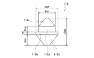
- FIG. 2B is a schematic side view of the protrusion shown in FIG. 1B.
- the side plates 101 and 102 for example, a metal plate such as stainless steel can be used.
- the JIS SUS304-H (spring material) is used.
- the dimension of the side plates 101 and 102 was set to 550 mm ⁇ 550 mm.
- the thickness of the side plates 101 and 102 is preferably 0.2 to 0.8 mm, for example, but here it is about 0.5 mm.
- the side plates 101 and 102 those in which the outer side surfaces 101a and 102a are mirror-finished can be used.
- the frame material 103 for example, a metal plate such as stainless steel can be used.
- the frame member 103 is formed by bending the side portions 103b and 103c sandwiching the central portion 103a at an obtuse angle and further bending the end portions 103d and 103e so as to be parallel to each other.
- the concave portions 101b and 102b of the side plates 101 and 102 are brought into contact with each other in the vicinity of the boundary between the central portion 103a and the side portions 103b and 103c.
- the total width W1 of the frame member 103 is, for example, 12 mm, and the length W2 of the contact portion with the side plates 101, 102 is, for example, 5 mm or less.
- the end portions 103 d and 103 e are in surface contact with the vicinity of the edge portions of the side plates 101 and 102.
- the inside of the sealed space 120 is set to a high vacuum, the vicinity of the central portion 103a is pressed from both sides by the concave portions 101b and 102b due to the pressure difference between the inside and outside of the sealed space 120. Thereby, even if the overall length of the frame member 103 is increased, sufficient strength can be obtained. Any other shape may be used as long as the path length of the heat conduction is longer than the distance between the side plates 101 and 102. Although only the frame member 103 is shown in FIG. 2A, the structures of the other frame members 104 to 106 are the same.
- the JIS SUS304-H is used as the metal material of the frame members 103 to 106, and the thickness of each of the frame members 103 to 106 is about 0.2 mm. Then, by fixing these frame members 103 to 106 by seam welding or the like, the frame 109 of the vacuum heat insulating panel 100 as shown by the dotted line in FIG. 1A was assembled. Further, seam welding was performed along each side of the side plates 101 and 102 to fix the frame members 103 to 106 and the side plates 101 and 102 in close contact with the welded portions 201 and 202. Seam welding is a type of resistance welding and is a method of continuously welding objects to be welded by rotating an electrode while applying pressure and energizing using a roller electrode.
- the inner plate 110 for example, a metal such as stainless steel can be used.
- the JIS SUS304-H is used as a material for forming the inner plate 110.
- the thickness of the inner plate 110 was about 0.2 mm.
- the inner plate 110 is disposed so as not to contact the frame members 103 to 106.
- the inner plate 110 is provided with a large number of through holes 111.
- the diameter of the through hole 111 is, for example, 6 mm.
- the protrusion 112 is inserted into the through hole 111.
- the protrusion 112 of the present embodiment includes a small-diameter columnar portion 112a (for example, 2 mm in height and 6 mm in diameter) and a large-diameter columnar portion 112b (for example, 1 mm in height and 8 mm in diameter). It is integrally formed so that one end surfaces may contact
- a small-diameter and substantially conical tip 112c (for example, 3 mm in height and 6 mm in diameter) is formed on the other end surface of the small-diameter cylindrical portion 112a, and a large-diameter and substantially conical on the other end surface of the large-diameter cylindrical portion 112c.
- 112d (for example, height 4mm, diameter 8mm) is integrally formed, respectively.
- these protrusions 112 are held by the inner plate 110 simply by inserting the small-diameter cylindrical portion 112a and the tip portion 112c into the through hole 111.
- one tip 112 c of the projection 112 abuts on the inner surface of the side plate 102 to support the side plate 102, and the other tip 112 d of the projection 112 is connected to the side plate 101.
- the side plate 101 is supported by contacting the inner side surface.
- tip portions 112c and 112d are substantially conical is to reduce the contact area between the projection 112 and the side plates 101 and 102, thereby suppressing heat conduction.
- the protrusion 112 is formed of a material having a lower thermal conductivity than that of the side plates 101 and 102 and the inner plate 110.
- the protrusion 112 is made of glass.
- the thermal conductivity of the JIS SUS304-H which is the material for forming the inner plate 110, is 18 W / mK (W is watts, m is meters, K is Kelvin), for example, whereas the thermal conductivity of glass is The rate is, for example, 0.7 W / mK.
- the protrusion 112 that can suppress deformation of the side plates 101 and 102 due to evacuation in the sealed space 120 and has extremely low thermal conductivity is formed at low cost. be able to.
- the protrusion 112 can be formed of a material other than glass.
- the load on the protrusion 112 is about 15 kg at the maximum (the same is true in the low vacuum, medium vacuum, and high vacuum of the JIS).
- ceramic has a thermal conductivity of about 0.6 W / mK and has a sufficiently high strength, and thus is suitable as the protrusion 112 of the present embodiment.
- the protrusion 112 is made of ceramic, there is an advantage that the protrusion 112 can be easily processed.
- the inner plate 110 is provided with a plurality of weight reduction through holes 113.
- the weight reduction through-hole 113 air flow can be facilitated when evacuating the sealed space 120.
- the size and number of the through holes 113 for weight reduction are arbitrary. However, in order to reduce the weight of the vacuum heat insulating panel 100, it is desirable to increase the total area of the weight reduction through-holes 113 within a range in which there is no problem in the strength of the inner plate 110.
- the diameter of the through hole 113 for weight reduction is 30 mm
- the pitch of the through hole 113 for weight reduction is 38 mm.
- the exhaust pipe 119 is used to evacuate the sealed space 120.
- the type of the exhaust pipe 119 and the like are not limited, but it is desirable to perform a process that can maintain the inside of the sealed space 120 in a vacuum state (for example, the high vacuum of JIS) for a long period of time.
- the exhaust pipe 119 has a double pipe structure, a stainless pipe having a diameter of about 10 mm and a length of about 1 mm is used as the outer pipe, and a copper pipe is used as the inner pipe.
- the exhaust pipe 119 was press-bonded after being evacuated, and the exhaust pipe 119 was pressure-bonded, and the outer end of the exhaust pipe 119 was welded. Thereby, the intrusion of atmospheric gas into the sealed space 120 can be prevented, and the sealed space 120 is maintained at, for example, the high vacuum of JIS.
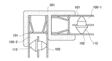
- FIG. 3A and 3B are examples in which a storage box is manufactured using the vacuum heat insulating panel 100 of the present embodiment
- FIG. 3A is an external perspective view
- FIG. 3B is a cross-sectional view along line BB in FIG. 3A.
- the storage box 300 has a substantially regular hexahedron shape, and is manufactured using six vacuum heat insulation panels 100. In FIG. 3A, only three vacuum heat insulation panels 100-1 to 100-3 are shown.
- the frame body 301 for example, a hard foam resin is used. As shown in FIG. 3B, the frame body 301 covers the ends of the two adjacent vacuum heat insulation panels 100 (the vacuum heat insulation panels 100-1 and 100-2 in FIG. 3B) and the vicinity thereof, These two vacuum heat insulation panels 100 are fixed so that the planes are at right angles. Thereby, each side of the six vacuum heat insulation panels 100 can be fixed to another adjacent vacuum heat insulation panel 100 to produce a substantially regular hexahedron containing box 300.
- the vacuum insulation panel 100-1 may be removed by pulling the frame 301 upward in FIG. 3B.
- FIG. 4A and FIG. 4B are other examples of the storage box created using the vacuum heat insulation panel 100 of this embodiment, FIG. 4A is an external perspective view, and FIG. 4B is a partial cross-sectional view.
- a box-shaped storage box body 401 having an upper opening 401a is formed by a single vacuum heat insulating panel.
- the side plates 402 and 403 and the inner plate 404 are each formed into a box shape by three-dimensional pressing.
- the protrusion 112 is loaded on the inner plate 404 and accommodated in the outer side plate 402, and further, the inner side plate 403 is accommodated in the inner plate 404.
- the upper opening 401a of the storage box body 401 can be closed by a lid (not shown).
- the lid one having the same configuration as the vacuum heat insulating panel 100 as shown in FIGS. 1A to 2B can be used.
- the inside of the sealed space 120 is set to, for example, a high vacuum (may be a medium vacuum or a low vacuum). For this reason, since heat conduction by the air convection in the sealed space 120 (heat conduction between the side plates 101 and 102) can be extremely reduced, sufficiently high heat insulation can be obtained.
- a high vacuum may be a medium vacuum or a low vacuum.
- the side plates 101 and 102 tend to be deformed inward by the negative pressure of the sealed space 120.
- a method for suppressing such deformation a method using a high-strength side plate or a method using an inner plate can be considered.
- a high-strength side plate is used in order to suppress this deformation, it is necessary to increase the thickness of the side plate, so that the total weight of the vacuum heat insulation panel 100 increases.
- the reinforcement means like the said patent document 1, since the weight of inner board itself is large, the total weight of the vacuum heat insulation panel 100 will become large.
- a plurality of through holes 111 are provided in the inner plate 110, the protruding portions 112 are inserted into the through holes 111, and both ends of the protruding portions 112 are connected to the side plates 101 and 102. It was supposed to be supported by contacting. For this reason, even if the inner plate 110 is formed very thin, the side plates 101 and 102 can be sufficiently reinforced. Therefore, according to the present embodiment, it is possible to obtain sufficient strength while reducing the weight of the vacuum heat insulating panel 100.
- the protrusion 112 is formed of glass or the like, which is a material having lower thermal conductivity than the side plates 101 and 102 and the inner plate 110. For this reason, it is difficult for heat to be conducted between the side plates 101 and 102 via the protrusion 112, and therefore, a very excellent heat insulating performance can be obtained.
- the frame members 103 to 106 have a bent structure as shown in FIG. 2A, so that the heat dissipation of these frame members 103 to 106 can be enhanced. Obtainable.
- the vacuum heat insulation panel 100 of the present embodiment makes the inside of the sealed space 120 in a vacuum state (high vacuum, medium vacuum, or low vacuum), and heat conduction through the protrusion 112 and the frame members 103 to 106. small. For this reason, even if the panel thickness is very thin, sufficiently high heat insulation performance can be obtained. That is, according to this embodiment, the vacuum heat insulation panel 100 with high heat insulation performance can be formed very thin.
- the panel thickness was 11 mm, and the thermal conductivity between the side plates 101 and 102 was 0.00030 W / mK.
- the thermal conductivity of the heat insulation panel using urethane foam is about 0.02 W / mK.
- the protrusion 112 is inserted into the through hole 111 of the inner plate 110 and both end portions of the protrusion 112 are brought into contact with the side plates 101, 102.
- the effects of the present invention can be obtained even with other structures.
- the vacuum heat insulating panel of the present invention can be used for heat insulating materials for various purposes such as transport containers, storage containers, refrigerators, freezers, vending machines, building wall materials, and heat shields for blast furnaces.
Abstract
A vacuum insulated panel that is lightweight, thin and has excellent insulating properties. A tightly sealed space is formed by disposing a pair of side panels to face each other and disposing four frame pieces along the various sides of the side panels. Using an exhaust port, the tightly sealed space is evacuated. In the tightly sealed space, an inner panel of stainless steel, etc. is disposed to be substantially parallel to the side panels. Multiple protrusions are disposed on the inner panel. As a result of the protrusions contacting the inner surface of the side panel with the tips thereof, the side panels are supported. The protrusions are formed from a material with a lower thermal conductivity than the inner panel such as glass or ceramic.
Description
本発明は、中空パネルの内部空間を真空引きしてなる真空断熱パネルに関する。
The present invention relates to a vacuum heat insulation panel formed by evacuating the internal space of a hollow panel.
断熱パネルは、冷蔵庫、保冷容器等の筐体や、航空輸送用コンテナの壁材等に使用されている。従来より、断熱パネルとして、一対の側板の間に発泡ウレタンや発泡ポリスチレン等の断熱材を埋設したものが知られている。しかし、これらの断熱材を用いて断熱パネルを作製する場合、十分な断熱性を得るためには、非常に厚い断熱材が必要になる。
Insulation panels are used for housings such as refrigerators and cold storage containers, and wall materials for air transport containers. 2. Description of the Related Art Conventionally, a heat insulating panel in which a heat insulating material such as urethane foam or polystyrene is embedded between a pair of side plates is known. However, when producing a heat insulating panel using these heat insulating materials, a very thick heat insulating material is required to obtain sufficient heat insulating properties.
また、中空パネルの内部空間を真空引きすることによって、かかるパネルの断熱性を向上させる技術が、従来より知られている。このような断熱パネルは、真空断熱パネルと呼ばれている。真空断熱パネルによれば、断熱材を使用しただけの場合と比較して、断熱性を向上させることができる。しかし、真空断熱パネルでは、内部空間の気圧と大気圧との差によって側板が変形して、側板どうしが接触し、側板間で直接熱が伝導するようになってしまうおそれがある。このため、真空断熱パネルには、かかる変形を抑えるための補強手段を設けることが望ましい。
Also, a technique for improving the heat insulation of such a panel by evacuating the internal space of the hollow panel is conventionally known. Such a heat insulation panel is called a vacuum heat insulation panel. According to the vacuum heat insulation panel, the heat insulation can be improved as compared with the case where only the heat insulating material is used. However, in the vacuum heat insulation panel, the side plates are deformed due to the difference between the atmospheric pressure and the atmospheric pressure in the internal space, the side plates come into contact with each other, and heat may be directly conducted between the side plates. For this reason, it is desirable to provide the vacuum heat insulation panel with a reinforcing means for suppressing such deformation.
例えば、下記特許文献1の技術では、凹凸を有する鋼板を積層することによって、真空断熱パネルの変形を抑制している(特許文献1の段落[0015]、図1等参照)。
For example, in the technique of Patent Document 1 below, the deformation of the vacuum heat insulating panel is suppressed by laminating uneven steel plates (see paragraph [0015] of FIG. 1, FIG. 1 and the like).
しかしながら、特許文献1の技術は、複数枚の鋼板を使用するため、真空断熱パネルの重量が大きくなるという欠点がある。
However, the technique of Patent Document 1 has a drawback that the weight of the vacuum heat insulation panel is increased because a plurality of steel plates are used.
また、かかる鋼板を介して2枚の側板の間で熱が伝導するようになるので、真空断熱パネルの断熱性能を悪化させるという欠点がある。
Also, since heat is conducted between the two side plates via the steel plate, there is a drawback that the heat insulating performance of the vacuum heat insulating panel is deteriorated.
さらには、このような鋼板を積層したので、真空断熱パネルの厚みを十分に低減することができないという欠点もある。例えば、このような真空断熱パネルを用いて輸送用コンテナを作製する場合が考えられるが、輸送用コンテナでは外形寸法が予め規定されている場合が多い。このため、真空断熱パネルの厚みが大きいほど内部容積が小さくなってしまい、積載容量が減ってしまう。
Furthermore, since such steel plates are laminated, there is a disadvantage that the thickness of the vacuum heat insulation panel cannot be reduced sufficiently. For example, a case where a shipping container is manufactured using such a vacuum heat insulating panel can be considered, but the outer dimensions of the shipping container are often defined in advance. For this reason, the larger the thickness of the vacuum heat insulation panel, the smaller the internal volume, and the load capacity decreases.
本発明の課題は、軽量で、厚みが小さく且つ断熱性能に優れた真空断熱パネルを提供する点にある。
An object of the present invention is to provide a vacuum heat insulation panel that is light in weight, small in thickness, and excellent in heat insulation performance.
本願発明に係る真空断熱パネルは、対向配置された一対の側板とこれら側板の各辺に沿って配置された4枚の枠材とを用いて形成された密閉空間と、該密閉空間を真空引きするための排気口と、前記密閉空間内に、前記一対の側板と略平行に配置された、内板と、少なくとも一方の前記側板の内側面に当接することにより、前記密閉空間の内外の気圧差によって前記一対の側板が変形することを抑制するために、該内板に設けられた、複数の突起部とを有し、前記突起部が、前記内板よりも熱伝導率の低い材料で形成されたことを特徴とする。
The vacuum heat insulation panel according to the present invention includes a sealed space formed by using a pair of side plates opposed to each other and four frame members arranged along each side of the side plates, and evacuating the sealed space. And an air pressure inside and outside of the sealed space by contacting an inner plate and an inner surface of at least one of the side plates disposed in the sealed space substantially parallel to the pair of side plates. In order to suppress the deformation of the pair of side plates due to the difference, the inner plate has a plurality of protrusions, and the protrusions are made of a material having a lower thermal conductivity than the inner plate. It is formed.
本願発明においては、前記突起部は、前記内板に設けられた貫通孔に挿通された状態で配置され、且つ、該突起部の両端部分が、それぞれ、前記一対の側板の各内側面に当接することが望ましい。
In the present invention, the protrusions are arranged in a state of being inserted through through holes provided in the inner plate, and both end portions of the protrusions respectively contact the inner surfaces of the pair of side plates. It is desirable to touch.
本願発明においては、前記突起部は、前記側板にそれぞれ当接する各先端部分が、略円錐形であることが望ましい。
In the invention of the present application, it is desirable that each of the protruding portions has a substantially conical shape at each tip portion that abuts on the side plate.
本願発明においては、前記突起部が、ガラス又はセラミックで形成されることが望ましい。
In the present invention, it is desirable that the protrusion is formed of glass or ceramic.
本願発明においては、前記内板の側面に1個又は複数個の軽量化用貫通孔が設けられることが望ましい。
In the present invention, it is desirable that one or more through holes for weight reduction be provided on the side surface of the inner plate.
本願発明においては、前記枠材は、平板の中央部分を挟む側部をそれぞれ鈍角に折り曲げられ、且つ、該側部のそれぞれの端部を互いに平行となるように折り曲げられ、これらの端部で、対応する前記側板に面接触すると共に、前記中央部分とそれぞれの前記側部との境界部付近に、それぞれの前記側板に設けられた突起部が当接されることが望ましい。
In the present invention, the frame member is bent at an obtuse angle at the side portions sandwiching the central portion of the flat plate, and the end portions of the side portions are bent so as to be parallel to each other. It is desirable that the corresponding side plate is in surface contact and a projection provided on each side plate is brought into contact with the vicinity of the boundary between the central portion and each side portion.
本願発明によれば、一対の側板と略平行に内板を配置し、該内板よりも熱伝導率が低い複数の突起部を当該内板に配置し、これら突起部を側板に当接させることによって、内部空間の気圧と大気圧との差による側板の変形を抑える。このため、本願発明によれば、突起部と側板との接触面積を非常に小さくすることができる。
According to the present invention, the inner plate is disposed substantially parallel to the pair of side plates, the plurality of protrusions having lower thermal conductivity than the inner plate are disposed on the inner plate, and these protrusions are brought into contact with the side plates. As a result, the deformation of the side plate due to the difference between the atmospheric pressure of the internal space and the atmospheric pressure is suppressed. For this reason, according to this invention, the contact area of a projection part and a side plate can be made very small.
従って、本願発明に係る真空断熱パネルでは、突起部と側板との間を伝導する熱が、非常に少ない。その結果、本願発明に係る真空断熱パネルによれば、非常に優れた断熱性能を得ることができる。
Therefore, in the vacuum heat insulation panel according to the present invention, there is very little heat conducted between the protrusion and the side plate. As a result, according to the vacuum heat insulation panel according to the present invention, very excellent heat insulation performance can be obtained.
以下、本発明の実施形態に係る真空断熱パネルについて、図面を用いて説明する。
[発明の実施の形態1]
図1A及び図1Bは、第1の実施形態に係る真空断熱パネル100の全体構成を示す概念図であり、図1Aは平面図、図1Bは図1AのA-A断面図である。 Hereinafter, the vacuum heat insulation panel which concerns on embodiment of this invention is demonstrated using drawing.
Embodiment 1 of the Invention
1A and 1B are conceptual views showing the overall configuration of the vacuumheat insulation panel 100 according to the first embodiment, FIG. 1A is a plan view, and FIG. 1B is a cross-sectional view taken along line AA in FIG. 1A.
[発明の実施の形態1]
図1A及び図1Bは、第1の実施形態に係る真空断熱パネル100の全体構成を示す概念図であり、図1Aは平面図、図1Bは図1AのA-A断面図である。 Hereinafter, the vacuum heat insulation panel which concerns on embodiment of this invention is demonstrated using drawing.
1A and 1B are conceptual views showing the overall configuration of the vacuum
図1A及び図1Bに示したように、本実施形態の真空断熱パネル100では、一対の側板101,102が、互いに向き合うように配置されている。また、側板101,102の間には、内板110が配置されている。さらに、側板101,102の各辺に沿って、枠材103~106が配置されており、側板101,102及び枠材103~106はそれぞれ互いに密着固定されている。これにより、側板101,102と枠材103~106とによる密閉空間120が形成されている。この密閉空間120は、排気管119を用いて、例えば高真空に真空引きされる。なお、本願で「高真空」とはJIS(日本工業規格)に規定された高真空、すなわち気圧が10-5Pa以上10-1Pa以下の状態をいう。本実施形態の真空断熱パネル100が中真空や低真空でも使用できることは、もちろんである。
As shown in FIG. 1A and FIG. 1B, in the vacuum heat insulation panel 100 of the present embodiment, the pair of side plates 101 and 102 are disposed so as to face each other. An inner plate 110 is arranged between the side plates 101 and 102. Further, the frame members 103 to 106 are disposed along the sides of the side plates 101 and 102, and the side plates 101 and 102 and the frame members 103 to 106 are fixed in close contact with each other. As a result, a sealed space 120 is formed by the side plates 101 and 102 and the frame members 103 to 106. The sealed space 120 is evacuated to a high vacuum, for example, using the exhaust pipe 119. In the present application, “high vacuum” refers to a high vacuum defined by JIS (Japanese Industrial Standards), that is, a state where the atmospheric pressure is 10 −5 Pa to 10 −1 Pa. Of course, the vacuum heat insulation panel 100 of this embodiment can be used even in a medium vacuum or a low vacuum.
以下、真空断熱パネル100の構成について、詳細に説明する。図2Aは図1Bに符号Xで示した部分の拡大図、図2Bは図1Bに示した突起部の概略的側面図である。
Hereinafter, the configuration of the vacuum heat insulation panel 100 will be described in detail. 2A is an enlarged view of a portion indicated by reference numeral X in FIG. 1B, and FIG. 2B is a schematic side view of the protrusion shown in FIG. 1B.
側板101,102としては、例えばステンレス等の金属板を使用することができる。本実施形態では、上記JISのSUS304-H(バネ材)を使用している。また、本実施形態では、側板101,102の寸法を、550mm×550mmとした。側板101,102の厚さは、例えば0.2~0.8mmが好ましいが、ここでは約0.5mmとした。また、側板101,102としては、外側面101a,102aが鏡面処理されたものを使用できる。
As the side plates 101 and 102, for example, a metal plate such as stainless steel can be used. In the present embodiment, the JIS SUS304-H (spring material) is used. Moreover, in this embodiment, the dimension of the side plates 101 and 102 was set to 550 mm × 550 mm. The thickness of the side plates 101 and 102 is preferably 0.2 to 0.8 mm, for example, but here it is about 0.5 mm. Further, as the side plates 101 and 102, those in which the outer side surfaces 101a and 102a are mirror-finished can be used.
枠材103としては、例えばステンレス等の金属板を使用することができる。図2Aに示したように、枠材103は、中央部分103aを挟む側部103b,103cを鈍角に折り曲げ、さらに端部103d,103eを互いに平行となるように折り曲げることで形成される。中央部分103aと側部103b,103cとの境界部付近には、側板101,102の凹部101b,102bが当接される。枠材103の全幅W1は例えば12mmであり、また、側板101,102との接触部分の長さW2は例えば5mm以下である。端部103d,103eは側板101,102の縁部付近と面接触している。
As the frame material 103, for example, a metal plate such as stainless steel can be used. As shown in FIG. 2A, the frame member 103 is formed by bending the side portions 103b and 103c sandwiching the central portion 103a at an obtuse angle and further bending the end portions 103d and 103e so as to be parallel to each other. The concave portions 101b and 102b of the side plates 101 and 102 are brought into contact with each other in the vicinity of the boundary between the central portion 103a and the side portions 103b and 103c. The total width W1 of the frame member 103 is, for example, 12 mm, and the length W2 of the contact portion with the side plates 101, 102 is, for example, 5 mm or less. The end portions 103 d and 103 e are in surface contact with the vicinity of the edge portions of the side plates 101 and 102.
このような構造によれば、側板101,102と側部103b,103cとの間に高真空の空間が形成されるので、該側板101,102と該側部103b,103cとの熱伝導を低く抑えることができる。また、側板101,102から端部103d,103eに伝搬した熱の大部分を、この枠材103で放熱させることができる。枠材103の放熱性を高めるためには、該枠材103の全長(すなわち、側板101,102間で熱が伝導するときの伝導経路の長さ)を長くするほど望ましい。本実施形態では、密閉空間120内を高真空にするので、該密閉空間120内外の気圧差により、中央部分103a付近が凹部101b,102bによって両側から押圧される。これにより、枠材103の全長を長くしても、十分な強度を得ることができる。なお、側板101,102間の距離よりも熱伝導の経路長の方が長くなるような折り曲げ形状であれば、他の形状であっても良い。図2Aでは枠材103のみを示したが、他の枠材104~106の構造も同様である。
According to such a structure, since a high vacuum space is formed between the side plates 101 and 102 and the side portions 103b and 103c, the heat conduction between the side plates 101 and 102 and the side portions 103b and 103c is reduced. Can be suppressed. Further, most of the heat propagated from the side plates 101 and 102 to the end portions 103 d and 103 e can be radiated by the frame member 103. In order to improve the heat dissipation of the frame member 103, it is desirable to increase the total length of the frame member 103 (that is, the length of the conduction path when heat is conducted between the side plates 101 and 102). In this embodiment, since the inside of the sealed space 120 is set to a high vacuum, the vicinity of the central portion 103a is pressed from both sides by the concave portions 101b and 102b due to the pressure difference between the inside and outside of the sealed space 120. Thereby, even if the overall length of the frame member 103 is increased, sufficient strength can be obtained. Any other shape may be used as long as the path length of the heat conduction is longer than the distance between the side plates 101 and 102. Although only the frame member 103 is shown in FIG. 2A, the structures of the other frame members 104 to 106 are the same.
本実施形態では、枠材103~106の金属材料として上記JISのSUS304-Hを使用し、また、枠材103~106の厚みをそれぞれ約0.2mmとした。そして、これら枠材103~106をシーム溶接等で固定することにより、図1Aに点線で示したような、真空断熱パネル100の枠109を組み立てた。さらに、側板101,102の各辺に沿ってシーム溶接を施すことにより、枠材103~106と側板101,102とを溶接部201,202で密着固定した。シーム溶接とは、抵抗溶接の一種であり、ローラ電極を用いて加圧且つ通電しながら電極を回転させることにより、溶接対象物を連続的に溶接する方法である。なお、枠材103~106や側板101,102の固定には、例えばアーク溶接等の、他の固定方法を使用してもよい。但し、かかる固定方法としては、ガスが発生しないような方法を採用することが望ましい。密閉空間120内の真空引き後に溶接部分からガスが漏れ出すと、真空度が低下して断熱効果が損なわれるおそれがあるためである。
In the present embodiment, the JIS SUS304-H is used as the metal material of the frame members 103 to 106, and the thickness of each of the frame members 103 to 106 is about 0.2 mm. Then, by fixing these frame members 103 to 106 by seam welding or the like, the frame 109 of the vacuum heat insulating panel 100 as shown by the dotted line in FIG. 1A was assembled. Further, seam welding was performed along each side of the side plates 101 and 102 to fix the frame members 103 to 106 and the side plates 101 and 102 in close contact with the welded portions 201 and 202. Seam welding is a type of resistance welding and is a method of continuously welding objects to be welded by rotating an electrode while applying pressure and energizing using a roller electrode. For fixing the frame members 103 to 106 and the side plates 101 and 102, other fixing methods such as arc welding may be used. However, as such a fixing method, it is desirable to employ a method that does not generate gas. This is because if the gas leaks from the welded portion after evacuating the sealed space 120, the degree of vacuum is lowered and the heat insulating effect may be impaired.
内板110としては、例えばステンレス等の金属を使用することができる。本実施形態では、内板110の形成材料として、上記JISのSUS304-Hを使用した。内板110の厚さは、約0.2mmとした。断熱性を高めるため、内板110は、枠材103~106と接触しないように配置される。
As the inner plate 110, for example, a metal such as stainless steel can be used. In the present embodiment, the JIS SUS304-H is used as a material for forming the inner plate 110. The thickness of the inner plate 110 was about 0.2 mm. In order to improve heat insulation, the inner plate 110 is disposed so as not to contact the frame members 103 to 106.
内板110には、多数の貫通孔111が設けられている。貫通孔111の直径は、例えば6mmである。この貫通孔111には、突起部112が挿通される。本実施形態の突起部112は、図2Bに示したように、小径の円柱部112a(例えば高さ2mm、直径6mm)と大径の円柱部112b(例えば高さ1mm、直径8mm)とが、一方の端面同士が接するように一体形成される。さらに、小径の円柱部112aの他方の端面には小径で略円錐形の先端部112c(例えば高さ3mm、直径6mm)が、大径の円柱部112cの他方の端面には大径で略円錐状の先端部112d(例えば高さ4mm、直径8mm)が、それぞれ一体に形成されている。本実施形態では、これらの突起部112は、単に、小径の円柱部112a及び先端部112cを貫通孔111に挿通することのみで、内板110に保持される。そして、密閉空間120内では、突起部112の一方の先端部112cが、側板102の内側面に当接して該側板102を支え、また、突起部112の他方の先端部112dが、側板101の内側面に当接して該側板101を支える。
The inner plate 110 is provided with a large number of through holes 111. The diameter of the through hole 111 is, for example, 6 mm. The protrusion 112 is inserted into the through hole 111. As shown in FIG. 2B, the protrusion 112 of the present embodiment includes a small-diameter columnar portion 112a (for example, 2 mm in height and 6 mm in diameter) and a large-diameter columnar portion 112b (for example, 1 mm in height and 8 mm in diameter). It is integrally formed so that one end surfaces may contact | connect. Furthermore, a small-diameter and substantially conical tip 112c (for example, 3 mm in height and 6 mm in diameter) is formed on the other end surface of the small-diameter cylindrical portion 112a, and a large-diameter and substantially conical on the other end surface of the large-diameter cylindrical portion 112c. 112d (for example, height 4mm, diameter 8mm) is integrally formed, respectively. In the present embodiment, these protrusions 112 are held by the inner plate 110 simply by inserting the small-diameter cylindrical portion 112a and the tip portion 112c into the through hole 111. In the sealed space 120, one tip 112 c of the projection 112 abuts on the inner surface of the side plate 102 to support the side plate 102, and the other tip 112 d of the projection 112 is connected to the side plate 101. The side plate 101 is supported by contacting the inner side surface.
先端部112c,112dを略円錐形としたのは、突部112と側板101,102との接触面積を小さくして、熱伝導を抑制するためのである。突部112と側板101,102との熱伝導を抑えることにより、突起部112を介して側板101,102間に熱が伝導し難くすることができる。
The reason why the tip portions 112c and 112d are substantially conical is to reduce the contact area between the projection 112 and the side plates 101 and 102, thereby suppressing heat conduction. By suppressing the heat conduction between the protrusion 112 and the side plates 101 and 102, it is possible to make it difficult for heat to be conducted between the side plates 101 and 102 via the protrusion 112.
該突起部112は、側板101,102や内板110の形成材料よりも熱伝導率の小さい材料で形成される。本実施形態では、突起部112を、ガラスで形成した。ここで、内板110の形成材料である上記JISのSUS304-Hの熱伝導率は例えば18W/mK(Wはワット、mはメートル、Kはケルビン)であるのに対して、ガラスの熱伝導率は例えば0.7W/mKである。
The protrusion 112 is formed of a material having a lower thermal conductivity than that of the side plates 101 and 102 and the inner plate 110. In the present embodiment, the protrusion 112 is made of glass. Here, the thermal conductivity of the JIS SUS304-H, which is the material for forming the inner plate 110, is 18 W / mK (W is watts, m is meters, K is Kelvin), for example, whereas the thermal conductivity of glass is The rate is, for example, 0.7 W / mK.
このようにして、本実施形態によれば、密閉空間120内の真空引きに起因する側板101,102の変形を抑えることができ且つ熱伝導率が非常に低い突起部112を、安価に形成することができる。
In this way, according to the present embodiment, the protrusion 112 that can suppress deformation of the side plates 101 and 102 due to evacuation in the sealed space 120 and has extremely low thermal conductivity is formed at low cost. be able to.
なお、側板101,102や内板110よりも熱伝導率の低いものであれば、ガラス以外の材料で突起部112を形成することも可能である。但し、本実施形態の真空断熱パネル100では、突起部112への荷重が最大15kg程度になる(上記JISの低真空、中真空及び高真空において、ほぼ同じである)。このため、かかる荷重に対して十分な強度を得られるような材料で、突起部112を形成することが望ましい。例えば、セラミックは、熱伝導率が0.6W/mK程度であり且つ強度も十分に大きいため、本実施形態の突起部112として好適である。加えて、突起部112をセラミックで形成する場合、当該突起部112の加工が容易になるという利点もある。
In addition, if the thermal conductivity is lower than that of the side plates 101 and 102 and the inner plate 110, the protrusion 112 can be formed of a material other than glass. However, in the vacuum heat insulation panel 100 of this embodiment, the load on the protrusion 112 is about 15 kg at the maximum (the same is true in the low vacuum, medium vacuum, and high vacuum of the JIS). For this reason, it is desirable to form the protrusion 112 with a material that can obtain sufficient strength against such a load. For example, ceramic has a thermal conductivity of about 0.6 W / mK and has a sufficiently high strength, and thus is suitable as the protrusion 112 of the present embodiment. In addition, when the protrusion 112 is made of ceramic, there is an advantage that the protrusion 112 can be easily processed.
本実施形態では、内板110に、軽量化用貫通孔113を複数個設けた。また、軽量化用貫通孔113を設けることにより、密閉空間120内の真空引きを行う際に、空気の流れを容易にすることもできる。軽量化用貫通孔113の寸法や個数等は、任意である。但し、真空断熱パネル100を軽量にするためには、内板110の強度に問題が生じない範囲内で、軽量化用貫通孔113の総面積を大きくすることが望ましい。例えば、軽量化用貫通孔113の直径は30mmであり、また、該軽量化用貫通孔113のピッチは38mmである。
In this embodiment, the inner plate 110 is provided with a plurality of weight reduction through holes 113. In addition, by providing the weight reduction through-hole 113, air flow can be facilitated when evacuating the sealed space 120. The size and number of the through holes 113 for weight reduction are arbitrary. However, in order to reduce the weight of the vacuum heat insulating panel 100, it is desirable to increase the total area of the weight reduction through-holes 113 within a range in which there is no problem in the strength of the inner plate 110. For example, the diameter of the through hole 113 for weight reduction is 30 mm, and the pitch of the through hole 113 for weight reduction is 38 mm.
排気管119は、密閉空間120を真空引きするために使用される。排気管119の種類等は限定されないが、密閉空間120内を長期間にわたって真空状態(例えば、上記JISの高真空)に維持できるような処理が施されることが望ましい。本実施形態では、排気管119を二重パイプ構造とし、外側パイプとして直径約10mm且つ長さ約1mmのステンレス・パイプを使用し、内側パイプとして銅パイプを使用した。そして、真空引き後にプレス加工して排気管119を高圧着し、さらに、排気管119の外側先端を溶接した。これにより、密閉空間120の内部への大気ガスの侵入を防止することができて、密閉空間120が例えば上記JISの高真空に維持される。
The exhaust pipe 119 is used to evacuate the sealed space 120. The type of the exhaust pipe 119 and the like are not limited, but it is desirable to perform a process that can maintain the inside of the sealed space 120 in a vacuum state (for example, the high vacuum of JIS) for a long period of time. In this embodiment, the exhaust pipe 119 has a double pipe structure, a stainless pipe having a diameter of about 10 mm and a length of about 1 mm is used as the outer pipe, and a copper pipe is used as the inner pipe. The exhaust pipe 119 was press-bonded after being evacuated, and the exhaust pipe 119 was pressure-bonded, and the outer end of the exhaust pipe 119 was welded. Thereby, the intrusion of atmospheric gas into the sealed space 120 can be prevented, and the sealed space 120 is maintained at, for example, the high vacuum of JIS.
図3A及び図3Bは、本実施形態の真空断熱パネル100を用いて収容箱を作製した例であり、図3Aは外観斜視図、図3Bは図3AのB-B断面図である。
3A and 3B are examples in which a storage box is manufactured using the vacuum heat insulating panel 100 of the present embodiment, FIG. 3A is an external perspective view, and FIG. 3B is a cross-sectional view along line BB in FIG. 3A.
図3Aに示したように、この収容箱300は、略正六面体の形状を有しており、6枚の真空断熱パネル100を用いて作製される。なお、図3Aでは、3枚の真空断熱パネル100-1~100-3のみを示した。
As shown in FIG. 3A, the storage box 300 has a substantially regular hexahedron shape, and is manufactured using six vacuum heat insulation panels 100. In FIG. 3A, only three vacuum heat insulation panels 100-1 to 100-3 are shown.
枠体301としては、例えば、硬質発泡樹脂が使用される。図3Bに示したように、枠体301は、隣接する2枚の真空断熱パネル100(図3Bでは真空断熱パネル100-1,100-2)の端部及びその近傍をそれぞれ覆うようにして、これら二枚の真空断熱パネル100を平面が直角になるように固定する。これにより、6枚の真空断熱パネル100の各辺を、隣接する他の真空断熱パネル100に固定して、略正六面体の収容箱300を作製することができる。
As the frame body 301, for example, a hard foam resin is used. As shown in FIG. 3B, the frame body 301 covers the ends of the two adjacent vacuum heat insulation panels 100 (the vacuum heat insulation panels 100-1 and 100-2 in FIG. 3B) and the vicinity thereof, These two vacuum heat insulation panels 100 are fixed so that the planes are at right angles. Thereby, each side of the six vacuum heat insulation panels 100 can be fixed to another adjacent vacuum heat insulation panel 100 to produce a substantially regular hexahedron containing box 300.
なお、収容箱300に貨物を収容する場合や該収容箱300から貨物を取り出す場合には、枠体301を図3Bの上方向に引き抜いて真空断熱パネル100-1を取り外せばよい。
Note that when the cargo is stored in the storage box 300 or when the cargo is taken out from the storage box 300, the vacuum insulation panel 100-1 may be removed by pulling the frame 301 upward in FIG. 3B.
図4A及び図4Bは、本実施形態の真空断熱パネル100を用いて作成した収容箱の他の例であり、図4Aは外観斜視図、図4Bは部分断面図である。
FIG. 4A and FIG. 4B are other examples of the storage box created using the vacuum heat insulation panel 100 of this embodiment, FIG. 4A is an external perspective view, and FIG. 4B is a partial cross-sectional view.
図4A及び図4Bの例では、上部開口401aを有する箱型の収容箱本体401を、1枚の真空断熱パネルによって形成する。このため、側板402,403及び内板404は、それぞれ、三次元プレス加工で箱型に形成される。そして、内板404に突起部112を装填して、外側の側板402内に収容し、さらに、この内板404内に内側の側板403収容する。収容箱本体401の上部開口401aは、図示しない蓋部によって塞ぐことができる。蓋部としては、図1A-図2Bに示したような真空断熱パネル100と同様の構成のものが使用できる。
4A and 4B, a box-shaped storage box body 401 having an upper opening 401a is formed by a single vacuum heat insulating panel. For this reason, the side plates 402 and 403 and the inner plate 404 are each formed into a box shape by three-dimensional pressing. Then, the protrusion 112 is loaded on the inner plate 404 and accommodated in the outer side plate 402, and further, the inner side plate 403 is accommodated in the inner plate 404. The upper opening 401a of the storage box body 401 can be closed by a lid (not shown). As the lid, one having the same configuration as the vacuum heat insulating panel 100 as shown in FIGS. 1A to 2B can be used.
以下、本実施形態に係る真空断熱パネル100の原理について説明する。
Hereinafter, the principle of the vacuum heat insulation panel 100 according to the present embodiment will be described.
本実施形態に係る真空断熱パネル100を使用する場合、密閉空間120内を例えば高真空(中真空又は低真空でもよい)に設定する。このため、密閉空間120内の空気対流による熱伝導(側板101,102間の熱伝導)を非常に少なくすることができるので、十分に高い断熱性を得ることができる。
When using the vacuum heat insulation panel 100 according to this embodiment, the inside of the sealed space 120 is set to, for example, a high vacuum (may be a medium vacuum or a low vacuum). For this reason, since heat conduction by the air convection in the sealed space 120 (heat conduction between the side plates 101 and 102) can be extremely reduced, sufficiently high heat insulation can be obtained.
その一方で、密閉空間120内を高真空にすると、該密閉空間120の負圧によって、側板101,102が内側に変形しようとする。かかる変形を抑制する方法としては、強度の高い側板を使用する方法や内板を使用する方法が考えられる。しかしながら、この変形を抑制するために強度の高い側板を使用する場合、かかる側板の板厚を厚くする必要が生じるので、真空断熱パネル100の総重量が大きくなってしまう。また、上記特許文献1のような補強手段を使用する場合も、内板自体の重量が大きいために真空断熱パネル100の総重量が大きくなってしまう。
On the other hand, when the inside of the sealed space 120 is made a high vacuum, the side plates 101 and 102 tend to be deformed inward by the negative pressure of the sealed space 120. As a method for suppressing such deformation, a method using a high-strength side plate or a method using an inner plate can be considered. However, when a high-strength side plate is used in order to suppress this deformation, it is necessary to increase the thickness of the side plate, so that the total weight of the vacuum heat insulation panel 100 increases. Moreover, also when using the reinforcement means like the said patent document 1, since the weight of inner board itself is large, the total weight of the vacuum heat insulation panel 100 will become large.
これに対して、本実施形態では、内板110に複数の貫通孔111を設けて、該貫通孔111にそれぞれ突起部112を挿通し、更に、かかる突起部112の両端を側板101,102に当接させて支持させることとした。このため、内板110を非常に薄く形成しても、側板101,102に対して十分な補強を行うことができる。したがって、本実施形態によれば、真空断熱パネル100を軽量化しつつ十分な強度を得ることができる。
On the other hand, in the present embodiment, a plurality of through holes 111 are provided in the inner plate 110, the protruding portions 112 are inserted into the through holes 111, and both ends of the protruding portions 112 are connected to the side plates 101 and 102. It was supposed to be supported by contacting. For this reason, even if the inner plate 110 is formed very thin, the side plates 101 and 102 can be sufficiently reinforced. Therefore, according to the present embodiment, it is possible to obtain sufficient strength while reducing the weight of the vacuum heat insulating panel 100.
本発明者の検討によれば、密閉空間120内が高真空の場合であっても、このような突起部112を使用するだけで十分な強度を得ることができた。
According to the study of the present inventor, even if the inside of the sealed space 120 is a high vacuum, it was possible to obtain a sufficient strength only by using such a protrusion 112.
また、本実施形態では、突起部112を、側板101,102や内板110よりも熱伝導性の小さい材料であるガラス等で形成した。このため、突起部112を介して側板101,102間に熱が伝導し難く、従って、非常に優れた断熱性能を得ることができる。
In the present embodiment, the protrusion 112 is formed of glass or the like, which is a material having lower thermal conductivity than the side plates 101 and 102 and the inner plate 110. For this reason, it is difficult for heat to be conducted between the side plates 101 and 102 via the protrusion 112, and therefore, a very excellent heat insulating performance can be obtained.
さらに、本実施形態では、枠材103~106を図2Aのような折り曲げ構造としたので、これら枠材103~106の放熱性を高めることができ、この点でも、非常に優れた断熱性能を得ることができる。
Furthermore, in this embodiment, the frame members 103 to 106 have a bent structure as shown in FIG. 2A, so that the heat dissipation of these frame members 103 to 106 can be enhanced. Obtainable.
このように、本実施形態の真空断熱パネル100は、密閉空間120内を真空状態(高真空、中真空又は低真空)にし、且つ、突起部112や枠材103~106を介した熱伝導が小さい。このため、パネル厚さを非常に薄くしても、十分に高い断熱性能を得ることができる。すなわち、本実施形態によれば、断熱性能の高い真空断熱パネル100を、非常に薄く形成することができる。本実施形態の真空断熱パネル100では、パネル厚さは11mm、両側板101,102間の熱伝導率は0.00030W/mKであった。これに対して、発泡ウレタンを用いた断熱パネルの熱伝導率は、0.02W/mK程度である。
As described above, the vacuum heat insulation panel 100 of the present embodiment makes the inside of the sealed space 120 in a vacuum state (high vacuum, medium vacuum, or low vacuum), and heat conduction through the protrusion 112 and the frame members 103 to 106. small. For this reason, even if the panel thickness is very thin, sufficiently high heat insulation performance can be obtained. That is, according to this embodiment, the vacuum heat insulation panel 100 with high heat insulation performance can be formed very thin. In the vacuum heat insulating panel 100 of this embodiment, the panel thickness was 11 mm, and the thermal conductivity between the side plates 101 and 102 was 0.00030 W / mK. On the other hand, the thermal conductivity of the heat insulation panel using urethane foam is about 0.02 W / mK.
以上説明したように、本実施形態によれば、軽量で、厚みが小さく且つ断熱性能に優れた真空断熱パネルを提供することができる。
As described above, according to this embodiment, it is possible to provide a vacuum thermal insulation panel that is lightweight, has a small thickness, and is excellent in thermal insulation performance.
なお、本実施形態では、内板110の貫通孔111に突起部112を挿通して、該突起部112の両端部を側板101,102に当接させる構造としたが、側板101,102や内板110よりも熱伝導率の低い突起部で側板101,102の内側面を支持する構造であれば、他の構造であっても本発明の効果を得ることができる。例えば、貫通孔111を設けずに、短尺の突起部を内板110の両側表面に固定して、それぞれ対応する側板101,102に当接させることとしてもよい。
In the present embodiment, the protrusion 112 is inserted into the through hole 111 of the inner plate 110 and both end portions of the protrusion 112 are brought into contact with the side plates 101, 102. As long as the structure supports the inner side surfaces of the side plates 101 and 102 with protrusions having lower thermal conductivity than the plate 110, the effects of the present invention can be obtained even with other structures. For example, without providing the through-hole 111, it is good also as fixing a short projection part to the both-sides surface of the inner board 110, and making it contact | abut to the corresponding side plates 101 and 102, respectively.
本発明の真空断熱パネルは、例えば輸送用コンテナ、保存容器、冷蔵庫、冷凍庫、自動販売機、建築物の壁材、溶鉱炉の遮熱板等、あらゆる用途の断熱材に使用できる。
The vacuum heat insulating panel of the present invention can be used for heat insulating materials for various purposes such as transport containers, storage containers, refrigerators, freezers, vending machines, building wall materials, and heat shields for blast furnaces.
100 真空断熱パネル
101,102 側板
103~106 枠材
109 枠
110 内板
111 貫通孔
112 突起部
113 軽量化用貫通孔
119 排気管
120 密閉空間
201,202 シーム溶接による溶接部分
300,400 収容箱
301 枠体
401 収容箱本体 DESCRIPTION OFSYMBOLS 100 Vacuum heat insulation panel 101,102 Side plate 103-106 Frame material 109 Frame 110 Inner plate 111 Through-hole 112 Projection part 113 Lightening through-hole 119 Exhaust pipe 120 Sealed space 201, 202 Welded part by seam welding 300, 400 Containment box 301 Frame body 401
101,102 側板
103~106 枠材
109 枠
110 内板
111 貫通孔
112 突起部
113 軽量化用貫通孔
119 排気管
120 密閉空間
201,202 シーム溶接による溶接部分
300,400 収容箱
301 枠体
401 収容箱本体 DESCRIPTION OF
Claims (6)
- 対向配置された一対の側板とこれら側板の各辺に沿って配置された4枚の枠材とを用いて形成された密閉空間と、
該密閉空間を真空引きするための排気口と、
前記密閉空間内に、前記一対の側板と略平行に配置された、内板と、
少なくとも一方の前記側板の内側面に当接することにより、前記密閉空間の内外の気圧差によって前記一対の側板が変形することを抑制するために、該内板に設けられた、複数の突起部と、
を有し、
前記突起部が、前記内板よりも熱伝導率の低い材料で形成されたことを特徴とする真空断熱パネル。 A sealed space formed using a pair of opposing side plates and four frame members arranged along each side of the side plates;
An exhaust port for evacuating the sealed space;
An inner plate disposed in the sealed space substantially parallel to the pair of side plates;
A plurality of protrusions provided on the inner plate in order to suppress deformation of the pair of side plates due to a pressure difference between the inside and outside of the sealed space by abutting on the inner surface of at least one of the side plates; ,
Have
The vacuum heat insulation panel, wherein the protrusion is formed of a material having a lower thermal conductivity than the inner plate. - 前記突起部は、前記内板に設けられた貫通孔に挿通された状態で配置され、
該突起部の両端部分が、それぞれ、前記一対の側板の各内側面に当接する、
ことを特徴とする請求項1に記載の真空断熱パネル。 The protrusion is arranged in a state of being inserted through a through hole provided in the inner plate,
Both end portions of the protrusions are in contact with the inner side surfaces of the pair of side plates, respectively.
The vacuum heat insulation panel according to claim 1. - 前記突起部は、前記側板にそれぞれ当接する各先端部分が、略円錐形であることを特徴とする請求項2に記載の真空断熱パネル。 3. The vacuum heat insulating panel according to claim 2, wherein each of the protrusions has a substantially conical shape at each tip portion that abuts on the side plate.
- 前記突起部が、ガラス又はセラミックで形成されたことを特徴とする請求項1に記載の真空断熱パネル。 2. The vacuum heat insulating panel according to claim 1, wherein the protrusion is formed of glass or ceramic.
- 前記内板の側面に1個又は複数個の軽量化用貫通孔が設けられたことを特徴とする請求項1に記載の真空断熱パネル。 The vacuum heat insulation panel according to claim 1, wherein one or more through holes for weight reduction are provided on a side surface of the inner plate.
- 前記枠材は、
平板の中央部分を挟む側部をそれぞれ鈍角に折り曲げられ、且つ、該側部のそれぞれの端部を互いに平行となるように折り曲げられ、
これらの端部で、対応する前記側板に面接触すると共に、
前記中央部分とそれぞれの前記側部との境界部付近に、それぞれの前記側板に設けられた突起部が当接される、
ことを特徴とする請求項1に記載の真空断熱パネル。 The frame material is
The side portions sandwiching the central portion of the flat plate are each bent at an obtuse angle, and the end portions of the side portions are bent so as to be parallel to each other,
At these ends, in surface contact with the corresponding side plate,
In the vicinity of the boundary between the central portion and each side portion, a protrusion provided on each side plate is in contact,
The vacuum heat insulation panel according to claim 1.
Applications Claiming Priority (2)
| Application Number | Priority Date | Filing Date | Title |
|---|---|---|---|
| JP2011140543A JP5890973B2 (en) | 2011-06-24 | 2011-06-24 | Vacuum insulation panel |
| JP2011-140543 | 2011-06-24 |
Publications (1)
| Publication Number | Publication Date |
|---|---|
| WO2012176880A1 true WO2012176880A1 (en) | 2012-12-27 |
Family
ID=47422708
Family Applications (1)
| Application Number | Title | Priority Date | Filing Date |
|---|---|---|---|
| PCT/JP2012/065997 WO2012176880A1 (en) | 2011-06-24 | 2012-06-22 | Vacuum insulated panel |
Country Status (2)
| Country | Link |
|---|---|
| JP (1) | JP5890973B2 (en) |
| WO (1) | WO2012176880A1 (en) |
Cited By (21)
| Publication number | Priority date | Publication date | Assignee | Title |
|---|---|---|---|---|
| CN110998168A (en) * | 2017-08-01 | 2020-04-10 | Lg电子株式会社 | Vacuum heat insulator, refrigerating or heating equipment, and method for manufacturing vacuum heat insulator |
| CN111750604A (en) * | 2015-08-03 | 2020-10-09 | Lg电子株式会社 | Refrigerator, vacuum heat insulator and method for manufacturing the same |
| CN111854307A (en) * | 2015-08-03 | 2020-10-30 | Lg电子株式会社 | Vacuum heat insulator |
| WO2021006640A1 (en) | 2019-07-09 | 2021-01-14 | Lg Electronics Inc. | Vacuum adiabatic module and refrigerator |
| EP3662193A4 (en) * | 2017-08-01 | 2021-04-21 | LG Electronics Inc. | Vacuum adiabatic body and refrigerator |
| US10995488B1 (en) | 2019-11-20 | 2021-05-04 | Whirlpool Corporation | Servicing assembly for an insulated structure |
| US11260727B2 (en) | 2017-08-01 | 2022-03-01 | Lg Electronics Inc. | Vehicle, refrigerator for vehicle, and controlling method for refrigerator for vehicle |
| US11274785B2 (en) | 2015-08-03 | 2022-03-15 | Lg Electronics Inc. | Vacuum adiabatic body and refrigerator |
| US11365931B2 (en) | 2015-08-04 | 2022-06-21 | Lg Electronics Inc. | Vacuum adiabatic body and refrigerator |
| US11466925B2 (en) | 2017-08-16 | 2022-10-11 | Lg Electronics Inc. | Vacuum adiabatic body and refrigerator |
| US11573048B2 (en) | 2015-08-03 | 2023-02-07 | Lg Electronics Inc. | Vacuum adiabatic body and refrigerator |
| US20230038053A1 (en) * | 2020-01-06 | 2023-02-09 | Qingdao Haier Refrigerator Co., Ltd. | Vacuum adiabatic body and refrigerator |
| US11585591B2 (en) | 2015-08-03 | 2023-02-21 | Lg Electronics Inc. | Vacuum adiabatic body and refrigerator |
| US11592230B2 (en) | 2015-08-03 | 2023-02-28 | Lg Electronics Inc. | Vacuum adiabatic body and refrigerator |
| US11598573B2 (en) | 2015-08-03 | 2023-03-07 | Lg Electronics Inc. | Vacuum adiabatic body and refrigerator |
| US11624550B2 (en) | 2017-08-01 | 2023-04-11 | Lg Electronics Inc. | Vacuum adiabatic body and refrigerator |
| US11774167B2 (en) | 2017-08-01 | 2023-10-03 | Lg Electronics Inc. | Vacuum adiabatic body and refrigerator |
| US11796246B2 (en) | 2015-08-03 | 2023-10-24 | Lg Electronics Inc. | Vacuum adiabatic body, fabrication method for the vacuum adiabatic body, porous substance package, and refrigerator |
| US11920858B2 (en) | 2015-08-03 | 2024-03-05 | Lg Electronics Inc. | Vacuum adiabatic body and refrigerator |
| US11920723B2 (en) | 2015-08-03 | 2024-03-05 | Lg Electronics Inc. | Vacuum adiabatic body and refrigerator |
| US11927386B2 (en) | 2015-08-03 | 2024-03-12 | Lg Electronics Inc. | Vacuum adiabatic body and refrigerator |
Families Citing this family (6)
| Publication number | Priority date | Publication date | Assignee | Title |
|---|---|---|---|---|
| KR102205476B1 (en) * | 2014-03-13 | 2021-01-20 | 삼성전자주식회사 | Vacuum heat insulating material and refrigerator including the same |
| JP2015187468A (en) * | 2014-03-27 | 2015-10-29 | 株式会社松田技術研究所 | Vacuum heat insulating pipe |
| KR102456642B1 (en) * | 2015-08-03 | 2022-10-19 | 엘지전자 주식회사 | Vacuum adiabatic body and refrigerator |
| KR20220059319A (en) * | 2020-11-02 | 2022-05-10 | 엘지전자 주식회사 | Vacuum adiabatic body and fabrication method for the same |
| KR20220059333A (en) * | 2020-11-02 | 2022-05-10 | 엘지전자 주식회사 | Vacuum adiabatic body and refrigerator |
| KR20230038046A (en) * | 2021-09-10 | 2023-03-17 | 삼성전자주식회사 | Refrigerator |
Citations (4)
| Publication number | Priority date | Publication date | Assignee | Title |
|---|---|---|---|---|
| JPH05509381A (en) * | 1990-06-12 | 1993-12-22 | ベンソン デービット ケイ. | Improved compact vacuum insulation |
| JP2002071088A (en) * | 2000-08-28 | 2002-03-08 | Matsuda Gijutsu Kenkyusho:Kk | Insulation panel |
| JP2003042388A (en) * | 2001-07-27 | 2003-02-13 | Matsuda Gijutsu Kenkyusho:Kk | Heat-insulating panel and container using it |
| JP2003147872A (en) * | 2001-11-12 | 2003-05-21 | Matsuda Gijutsu Kenkyusho:Kk | Metallic high-vacuum heat insulating panel |
Family Cites Families (1)
| Publication number | Priority date | Publication date | Assignee | Title |
|---|---|---|---|---|
| JP2005114028A (en) * | 2003-10-07 | 2005-04-28 | Mimatsu Gyoumuten:Kk | Vacuum panel/heat insulating material laminated heat insulation plate |
-
2011
- 2011-06-24 JP JP2011140543A patent/JP5890973B2/en active Active
-
2012
- 2012-06-22 WO PCT/JP2012/065997 patent/WO2012176880A1/en active Application Filing
Patent Citations (4)
| Publication number | Priority date | Publication date | Assignee | Title |
|---|---|---|---|---|
| JPH05509381A (en) * | 1990-06-12 | 1993-12-22 | ベンソン デービット ケイ. | Improved compact vacuum insulation |
| JP2002071088A (en) * | 2000-08-28 | 2002-03-08 | Matsuda Gijutsu Kenkyusho:Kk | Insulation panel |
| JP2003042388A (en) * | 2001-07-27 | 2003-02-13 | Matsuda Gijutsu Kenkyusho:Kk | Heat-insulating panel and container using it |
| JP2003147872A (en) * | 2001-11-12 | 2003-05-21 | Matsuda Gijutsu Kenkyusho:Kk | Metallic high-vacuum heat insulating panel |
Cited By (33)
| Publication number | Priority date | Publication date | Assignee | Title |
|---|---|---|---|---|
| US11920858B2 (en) | 2015-08-03 | 2024-03-05 | Lg Electronics Inc. | Vacuum adiabatic body and refrigerator |
| US11796246B2 (en) | 2015-08-03 | 2023-10-24 | Lg Electronics Inc. | Vacuum adiabatic body, fabrication method for the vacuum adiabatic body, porous substance package, and refrigerator |
| CN111854307A (en) * | 2015-08-03 | 2020-10-30 | Lg电子株式会社 | Vacuum heat insulator |
| US11927386B2 (en) | 2015-08-03 | 2024-03-12 | Lg Electronics Inc. | Vacuum adiabatic body and refrigerator |
| US11920723B2 (en) | 2015-08-03 | 2024-03-05 | Lg Electronics Inc. | Vacuum adiabatic body and refrigerator |
| US11920857B2 (en) | 2015-08-03 | 2024-03-05 | Lg Electronics Inc. | Vacuum adiabatic body and refrigerator |
| CN111750604A (en) * | 2015-08-03 | 2020-10-09 | Lg电子株式会社 | Refrigerator, vacuum heat insulator and method for manufacturing the same |
| US11137201B2 (en) | 2015-08-03 | 2021-10-05 | Lg Electronics Inc. | Vacuum adiabatic body and refrigerator |
| CN111854307B (en) * | 2015-08-03 | 2023-01-24 | Lg电子株式会社 | Vacuum heat insulator |
| US11274785B2 (en) | 2015-08-03 | 2022-03-15 | Lg Electronics Inc. | Vacuum adiabatic body and refrigerator |
| US11573048B2 (en) | 2015-08-03 | 2023-02-07 | Lg Electronics Inc. | Vacuum adiabatic body and refrigerator |
| US11598573B2 (en) | 2015-08-03 | 2023-03-07 | Lg Electronics Inc. | Vacuum adiabatic body and refrigerator |
| US11592230B2 (en) | 2015-08-03 | 2023-02-28 | Lg Electronics Inc. | Vacuum adiabatic body and refrigerator |
| US11585591B2 (en) | 2015-08-03 | 2023-02-21 | Lg Electronics Inc. | Vacuum adiabatic body and refrigerator |
| US11365931B2 (en) | 2015-08-04 | 2022-06-21 | Lg Electronics Inc. | Vacuum adiabatic body and refrigerator |
| US11260727B2 (en) | 2017-08-01 | 2022-03-01 | Lg Electronics Inc. | Vehicle, refrigerator for vehicle, and controlling method for refrigerator for vehicle |
| US11807075B2 (en) | 2017-08-01 | 2023-11-07 | Lg Electronics Inc. | Vehicle, refrigerator for vehicle, and controlling method for refrigerator for vehicle |
| EP3662193A4 (en) * | 2017-08-01 | 2021-04-21 | LG Electronics Inc. | Vacuum adiabatic body and refrigerator |
| EP3662192A4 (en) * | 2017-08-01 | 2021-04-28 | LG Electronics Inc. | Vacuum adiabatic body, refrigerating or warming apparatus, fabrication method for the vacuum adiabatic body |
| US11536415B2 (en) | 2017-08-01 | 2022-12-27 | Lg Electronics Inc. | Vacuum adiabatic body and refrigerator |
| CN110998168A (en) * | 2017-08-01 | 2020-04-10 | Lg电子株式会社 | Vacuum heat insulator, refrigerating or heating equipment, and method for manufacturing vacuum heat insulator |
| US11624550B2 (en) | 2017-08-01 | 2023-04-11 | Lg Electronics Inc. | Vacuum adiabatic body and refrigerator |
| US11774167B2 (en) | 2017-08-01 | 2023-10-03 | Lg Electronics Inc. | Vacuum adiabatic body and refrigerator |
| US11725768B2 (en) | 2017-08-01 | 2023-08-15 | Lg Electronics Inc. | Vacuum adiabatic body, refrigerating or warming apparatus, and method for manufacturing vacuum adiabatic body |
| US11781802B2 (en) | 2017-08-16 | 2023-10-10 | Lg Electronics Inc. | Vacuum adiabatic body and refrigerator |
| US11466925B2 (en) | 2017-08-16 | 2022-10-11 | Lg Electronics Inc. | Vacuum adiabatic body and refrigerator |
| EP3997402A4 (en) * | 2019-07-09 | 2023-07-12 | LG Electronics Inc. | Vacuum adiabatic module and refrigerator |
| US20220235997A1 (en) * | 2019-07-09 | 2022-07-28 | Lg Electronics Inc. | Vacuum adiabatic module and refrigerator |
| WO2021006640A1 (en) | 2019-07-09 | 2021-01-14 | Lg Electronics Inc. | Vacuum adiabatic module and refrigerator |
| US11788280B2 (en) | 2019-11-20 | 2023-10-17 | Whirlpool Corporation | Servicing assembly for an insulated structure |
| US11427998B2 (en) | 2019-11-20 | 2022-08-30 | Whirlpool Corporation | Servicing assembly for an insulated structure |
| US10995488B1 (en) | 2019-11-20 | 2021-05-04 | Whirlpool Corporation | Servicing assembly for an insulated structure |
| US20230038053A1 (en) * | 2020-01-06 | 2023-02-09 | Qingdao Haier Refrigerator Co., Ltd. | Vacuum adiabatic body and refrigerator |
Also Published As
| Publication number | Publication date |
|---|---|
| JP2013007439A (en) | 2013-01-10 |
| JP5890973B2 (en) | 2016-03-22 |
Similar Documents
| Publication | Publication Date | Title |
|---|---|---|
| WO2012176880A1 (en) | Vacuum insulated panel | |
| JP6083939B2 (en) | Vacuum insulation panel and insulation box | |
| JP2012207682A (en) | Vacuum heat insulation panel | |
| JP2012021615A (en) | Vacuum heat insulating panel and transportation container using the same | |
| EP3332193B1 (en) | Vacuum adiabatic body | |
| EP2589906B1 (en) | Refrigerator | |
| JP5313800B2 (en) | Thermal insulation panel | |
| KR101572823B1 (en) | vacuum insulation panel | |
| JP2010501793A (en) | Vacuum insulating panel and manufacturing method thereof | |
| JP2003269688A (en) | Evacuated heat insulating panel | |
| CN110249193B (en) | Vacuum insulator and refrigerator | |
| JP2005214372A (en) | Sealed heat insulation structure and inter-heat insulation wall surface reinforcement method | |
| EP2931988B1 (en) | A thermal insulation panel | |
| US20230010720A1 (en) | Machine compartment for a vacuum insulated structure | |
| JP2003147872A (en) | Metallic high-vacuum heat insulating panel | |
| US9687089B2 (en) | Insulated foam panels for refrigerated display cases | |
| JP2017110813A (en) | Vacuum heat insulation panel and heat insulation box body | |
| JP2013015168A (en) | Vacuum heat insulation panel | |
| JP5969359B2 (en) | Manufacturing method of vacuum insulation panel | |
| JP2012215293A (en) | Vacuum heat insulation structure | |
| WO2016098840A1 (en) | Multilayer glass | |
| WO2005057077A1 (en) | Heat insulating panel and heat insulating structure utilizing the heat insulating panel | |
| JP2014009723A (en) | Heat insulating material and heating device including the same | |
| JP2004232735A (en) | Evacuated heat insulating panel | |
| JP2013245813A (en) | Heat insulating material |
Legal Events
| Date | Code | Title | Description |
|---|---|---|---|
| 121 | Ep: the epo has been informed by wipo that ep was designated in this application |
Ref document number: 12803174 Country of ref document: EP Kind code of ref document: A1 |
|
| NENP | Non-entry into the national phase |
Ref country code: DE |
|
| 122 | Ep: pct application non-entry in european phase |
Ref document number: 12803174 Country of ref document: EP Kind code of ref document: A1 |