WO2012176673A1 - 管継手の固定構造 - Google Patents
管継手の固定構造 Download PDFInfo
- Publication number
- WO2012176673A1 WO2012176673A1 PCT/JP2012/065157 JP2012065157W WO2012176673A1 WO 2012176673 A1 WO2012176673 A1 WO 2012176673A1 JP 2012065157 W JP2012065157 W JP 2012065157W WO 2012176673 A1 WO2012176673 A1 WO 2012176673A1
- Authority
- WO
- WIPO (PCT)
- Prior art keywords
- joint
- male
- female
- fixing
- pipe
- Prior art date
- Legal status (The legal status is an assumption and is not a legal conclusion. Google has not performed a legal analysis and makes no representation as to the accuracy of the status listed.)
- Ceased
Links
Images


Classifications
-
- F—MECHANICAL ENGINEERING; LIGHTING; HEATING; WEAPONS; BLASTING
- F16—ENGINEERING ELEMENTS AND UNITS; GENERAL MEASURES FOR PRODUCING AND MAINTAINING EFFECTIVE FUNCTIONING OF MACHINES OR INSTALLATIONS; THERMAL INSULATION IN GENERAL
- F16L—PIPES; JOINTS OR FITTINGS FOR PIPES; SUPPORTS FOR PIPES, CABLES OR PROTECTIVE TUBING; MEANS FOR THERMAL INSULATION IN GENERAL
- F16L39/00—Joints or fittings for double-walled or multi-channel pipes or pipe assemblies
-
- H—ELECTRICITY
- H01—ELECTRIC ELEMENTS
- H01M—PROCESSES OR MEANS, e.g. BATTERIES, FOR THE DIRECT CONVERSION OF CHEMICAL ENERGY INTO ELECTRICAL ENERGY
- H01M10/00—Secondary cells; Manufacture thereof
- H01M10/60—Heating or cooling; Temperature control
- H01M10/61—Types of temperature control
- H01M10/613—Cooling or keeping cold
-
- H—ELECTRICITY
- H01—ELECTRIC ELEMENTS
- H01M—PROCESSES OR MEANS, e.g. BATTERIES, FOR THE DIRECT CONVERSION OF CHEMICAL ENERGY INTO ELECTRICAL ENERGY
- H01M10/00—Secondary cells; Manufacture thereof
- H01M10/60—Heating or cooling; Temperature control
- H01M10/62—Heating or cooling; Temperature control specially adapted for specific applications
- H01M10/625—Vehicles
-
- H—ELECTRICITY
- H01—ELECTRIC ELEMENTS
- H01M—PROCESSES OR MEANS, e.g. BATTERIES, FOR THE DIRECT CONVERSION OF CHEMICAL ENERGY INTO ELECTRICAL ENERGY
- H01M10/00—Secondary cells; Manufacture thereof
- H01M10/60—Heating or cooling; Temperature control
- H01M10/65—Means for temperature control structurally associated with the cells
- H01M10/656—Means for temperature control structurally associated with the cells characterised by the type of heat-exchange fluid
- H01M10/6567—Liquids
-
- Y—GENERAL TAGGING OF NEW TECHNOLOGICAL DEVELOPMENTS; GENERAL TAGGING OF CROSS-SECTIONAL TECHNOLOGIES SPANNING OVER SEVERAL SECTIONS OF THE IPC; TECHNICAL SUBJECTS COVERED BY FORMER USPC CROSS-REFERENCE ART COLLECTIONS [XRACs] AND DIGESTS
- Y02—TECHNOLOGIES OR APPLICATIONS FOR MITIGATION OR ADAPTATION AGAINST CLIMATE CHANGE
- Y02E—REDUCTION OF GREENHOUSE GAS [GHG] EMISSIONS, RELATED TO ENERGY GENERATION, TRANSMISSION OR DISTRIBUTION
- Y02E60/00—Enabling technologies; Technologies with a potential or indirect contribution to GHG emissions mitigation
- Y02E60/10—Energy storage using batteries
Definitions
- the present invention relates to a pipe joint fixing structure in which two joints constituting the pipe joint are fixed to different objects.
- FIG. 5 is a cross-sectional view showing a cross-sectional structure of a pipe joint in a conventional example.
- the pipe joint 100 described in Patent Document 1 includes a first joint 110 fixed to one end of the first pipe 101, and a second joint 120 fixed to one end of the second pipe 102. It is composed of
- the first joint 110 includes a main body 111 connected to the first pipe 101 and a slider 112 in which the main body 111 is inserted.
- the main body 111 has a substantially cylindrical shape, and a flange portion 111 a formed at the edge of the main body 111 is connected to the first pipe 101.
- the slider 112 includes a cylindrical portion 112a in which the main body 111 is slidably inserted, and a flange portion 112b formed at an edge of the cylindrical portion 112a.
- the second joint 120 includes a main body 121 to which the second pipe 102 is connected, and a connecting member 122 that sandwiches the flange portion 112b formed on the slider 112 of the first joint 110 with the main body 121.
- the main body 121 has a multi-stage cylindrical shape, a small diameter portion 121a having a flange portion to which the second pipe 102 is connected at an end edge, a large diameter portion 121b to which the connecting member 122 is connected, and these small diameter portions. It is comprised by the level
- the connecting member 122 has a substantially annular shape that allows the cylindrical portion 112a of the slider 112 to be inserted therein.
- the connecting member 122 When the connecting member 122 is connected to the large diameter portion 121b of the main body 121, the step portion 121c and the large diameter of the main body 121 are connected. A housing recess 123 extending in the radial direction is formed by the portion 121b.
- the connecting member 122 When the first joint 110 and the second joint 120 are connected, the connecting member 122 is connected to the main body 121 of the second joint 120 so that the flange 112b of the slider 112 is received in the receiving recess 123. Is done.
- the first and second joints are provided with seal members at various locations in order to prevent the flowing fluid from leaking to the outside.
- the diameter of the fixed object of the second joint 120 with respect to the fixed object of the first joint 110 is reduced in diameter with the first joint 110 and the second joint 120 connected to each other.
- a load displaced in the direction acts.
- the gap between the first joint 110 and the second joint 120 in the housing recess 123 is used to The pipe 101 moves with respect to the second pipe 102. Therefore, even when the above load acts on the fixing structure of the pipe joint, the connection between the first joint 110 and the second joint 120 is released, or the pipe joint 100 itself is deformed. It is possible to suppress.
- the displacement larger than the clearance gap between the 1st coupling 110 and the 2nd coupling 120 in the accommodation recessed part 123 is the 1st piping 101 and 2nd coupling which are the fixed objects of the 1st coupling 110
- the connection between the first joint 110 and the second joint 120 is released, or the pipe joint 100 itself is deformed. That is, in protecting the pipe joint 100 in the connected state, the above-described configuration still leaves room for improvement.
- the present invention has been made in view of the above circumstances, and an object of the present invention is to provide a fixing structure for a pipe joint that can enhance the protection of the pipe joint in a connected state.
- the first joint connected to the first pipe of the first object is fixed to the first object among the pipe joints composed of the first joint and the second joint that can be connected to each other.
- the second joint connected to the second pipe of the second object is a fixing structure of a pipe joint fixed to the second object, and the first joint with respect to the first object.
- the connection portion between the first joint and the second joint and the first fixing member are also affected.
- a load will act.
- the breaking stress of the first fixing member is larger than the breaking stress of the connecting portion
- the connection of the connecting portion is released before the fixing by the first fixing member is released.
- the fixing structure of the pipe joint of the present invention since the fracture stress of the first fixing member is smaller than the fracture stress of the connecting portion, the fixing by the first fixing member is performed before the connecting portion is released. Will be canceled.
- the shear strength of the first fixing member in the direction intersecting the direction in which the first joint and the second joint are connected is determined by the shear of the connection portion between the first joint and the second joint. It is preferably smaller than the strength.
- the first fixing member is more easily sheared than the connecting portion in the direction intersecting with the connecting direction of the first joint and the second joint. Therefore, when protecting the pipe joint in a connected state, it is possible to particularly improve the protection against stress in the direction crossing the connection direction.
- the first fixing member is a member extending in a connecting direction of the first joint and the second joint.
- the direction in which the first joint and the second joint are connected matches the longitudinal direction of the first fixing member. That is, the first fixing member has the largest rigidity in the direction in which the first joint and the second joint are connected, and becomes smaller as the direction approaches the direction orthogonal to the connecting direction. Therefore, the structural design of the first fixing member can be facilitated particularly for enhancing the protection against the stress in the direction crossing the connecting direction.
- the first fixing member has a notch at a portion facing a boundary between the first joint and the first object.
- the rigidity of the first fixing member is particularly reduced at the boundary between the first joint and the first object. Since a shearing force based on a load acting on the first object is generated in the vicinity of such a boundary, the first fixing member can be sheared at a site near the boundary. As a result, it can suppress that the 1st fixing member after shearing prevents the movement of a 1st target object.
- the present invention includes a second fixing member that fixes the second joint to the second object, wherein the second pipe is a flexible pipe, and the fracture stress of the second fixing member is It is preferable that the breaking stress is smaller than the breaking stress of the connecting portion between the first joint and the second joint.
- the pipe joint fixing structure of this preferred aspect since the fracture stress of the second fixing member is smaller than the fracture stress of the connecting portion, the fixing by the second fixing member is released before the connection of the connecting portion is released. Will be. Therefore, even if the stresses acting on the first fixing member and the second fixing member are different from each other, the fixing is released in the member on which the large stress acts. As a result, it is possible to improve the protection of the pipe joint in the connected state with higher certainty.
- FIG. 2 is a cross-sectional view showing a cross-sectional structure taken along line 2-2 in FIG.
- the pipe joint 10 includes a male member 20 having a male joint 21 as a first joint, and the male joint 21 inserted by the male joint 21 along the axial direction A. And a female member 30 having a female joint 31 as a second joint.
- the rectangular flat male side base 22 constituting the male member 20 is made of polyamide, and two male joints 21 are fixed at predetermined intervals along the longitudinal direction thereof.
- the male base body 22 is provided with two guide pins 23 having a substantially cylindrical shape so as to sandwich the two male joints 21 in the longitudinal direction.
- a square cylindrical defense wall 24 is fixed to the male base body 22 so as to surround the male joint 21 and the guide pin 23.
- a through-hole (not shown) is formed in each corner of the male side base 22, and a first fixing member used when fixing the male member 20 to the bracket 5 as the first object is formed in the through-hole. 25 (hereinafter simply referred to as a fixing member 25) is inserted so as to protrude from the back surface 22b.
- the rectangular flat female side base 32 constituting the female member 30 is made of polyamide, and two female joints 31 are fixed at the same interval as the male joint 21 along the longitudinal direction thereof.
- the female base body 32 is provided with two guide members 33 having a substantially cylindrical shape so as to sandwich the two female joints 31 in the longitudinal direction.
- the guide member 33 is erected at a position corresponding to each of the two guide pins 23 formed in the male member 20, and a guide hole 34 through which the guide pin 23 can be inserted is formed.
- through holes are formed in the respective corners of the female side base 32, and the second holes used when the female member 30 is fixed to the bracket 6 as the second object are formed in the through holes.
- the fixing member 35 (hereinafter simply referred to as the fixing member 35) is inserted so as to protrude from the back surface 32b.
- the male member 20 and the female member 30 When the male member 20 and the female member 30 are connected, the male member 20 and the female member 30 are opposed to each other in the axial direction A so that each guide pin 23 enters the guide hole 34 of the guide member 33.
- the bracket 5 When the bracket 5 is moved along the axial direction A to bring the male member 20 and the female member 30 closer, the male joints 21 are guided by the guide pins 23 that have entered the guide holes 34 and the female joints 31. Plugged into. In the connected state, the male joint 21 and the female joint 31 are surrounded by the defense wall 24.
- the pipe joint 10 described above is used in a cooling system for cooling a battery of an electric vehicle.
- cooling water cooled by a cooling device arranged on the vehicle body side is circulated between the vehicle body and the battery.
- the male member 20 is fixed to the bracket 5 provided on the battery side
- the female member 30 is provided on the bracket 6 provided on the vehicle body side. Fixed to.
- the bracket 5 is formed with an insertion port 5a into which a connecting portion 46 of the male joint 21 described later is inserted.
- the connector 5 is fixed to the bracket 5 with the connecting portion 46 inserted into the opening 5a.
- the bracket 6 is formed with an insertion port 6a into which a connecting portion 71 of a female joint 31 described later is inserted. The connection portion 71 is inserted into the insertion port and fixed to the bracket 6.
- the connecting portion 46 of the male joint 21 is a piping member fixed on the battery side, and for example, a piping member 7 as a flexible first piping such as a rubber hose. Connected with a margin in length.
- the connecting portion 71 of the female joint 31 is a piping member fixed to the vehicle body, and a piping member 8 as a flexible second piping such as a rubber hose has a margin in its length.
- the connection is made in the (Male member 20)
- the male joint 21 is disposed in the male base body 22 so as to penetrate the mounting hole 41 having a multistage cylindrical shape whose diameter is reduced on the back surface 22b side by the mounting seat 22c.
- the male joint 21 includes a male connector 42 to which an external pipe is connected and a male cylinder 43 supported by the male connector 42.
- the male connection body 42 is made of polyamide, and has a multistage cylindrical shape in which a flow path 44 is formed inside and extends along the axial direction A, and the central axis thereof coincides with the central axis of the mounting hole 41. It is arranged like this.
- the male connection body 42 is disposed in the attachment hole 41 and engages with the attachment seat 22c.
- the male connection body 42 is formed with an outer diameter smaller than that of the engagement part 45 and is formed from the back surface 22b of the male base body 22.
- the projecting connecting portion 46 is integrally formed.
- the male side cylinder 43 is made of polyamide, has an outer diameter that is larger than the inner diameter of the connection part 46 of the male side connection body 42 and smaller than the inner diameter of the engagement part 45, and is along the axial direction A. It has a substantially cylindrical shape that extends.
- the male cylinder 43 is disposed with one end loosely fitted inside the engaging portion 45 of the male connector 42 so that the central axis thereof coincides with the central axis of the mounting hole 41.
- a channel 47 communicating with the channel 44 of the male connector 42 is formed inside.
- a flange part 43 a having an outer diameter substantially equal to the outer diameter of the engaging part 45 of the male side connection body 42 and disposed in the attachment hole 41 is formed.
- the male side cylinder 43 is supported by the male side connection body 42 when the collar portion 43 a abuts on the engagement portion 45 of the male side connection body 42.
- An annular seal member 49 is disposed in a gap formed between the outer peripheral surface of the male cylinder 43 and the inner peripheral surface of the engagement portion 45 of the male connector 42 so that the internal fluid does not leak through the gap. Has been.
- the male joint 21 is a fixing plate that covers the flange 43a in a state where the engagement portion 45 of the male connector 42 and the flange 43a of the male cylinder 43 are disposed in the attachment hole 41. 50 is fixed to the male base 22 by being screwed onto the surface 22a of the male base 22 with screws (not shown).
- a male side pressing portion 51 is formed which is inserted into the female joint 31 and presses a female side valve body 84 to be described later with a pressing surface 51a.
- the male side valve seat 53 has a male side valve hole 53 having a diameter smaller than the flow path 47 of the male side cylindrical body 43 opened at the pressing surface 51a, and the entire circumference of the outer peripheral surface.
- An annular seal member 54 is mounted in the groove portion that is recessed over.
- a male side valve element 55 that can slide along the axial direction A inside the male side cylinder 43 is disposed.
- the male side valve body 55 has a substantially covered cylindrical shape made of polyamide, and is arranged so that the central axis thereof coincides with the central axis of the male side cylindrical body 43, and the male side connection body 42.
- the lower end of the coil spring 56 is biased toward the male valve hole 53.
- the male side valve body 55 has a base end portion 55a having an outer diameter slightly smaller than the inner diameter of the male side cylindrical body 43, and an outer diameter smaller than the base end portion 55a and blocks the male side valve hole 53.
- the tip portion 55b is integrally formed.
- the male valve body 55 has a male end valve hole 53 at a position where the end surface of the distal end portion 55b is flush with the pressing surface 51a of the male side pressing portion 51 by the base end portion 55a coming into contact with the male side valve seat 52. Displacement to the side is restricted.
- a guide pin 23 is disposed on the left side of the male joint 21 in the male base body 22.
- the guide pin 23 has a substantially cylindrical shape extending along the axial direction A, and the distal end portion 23a is gradually reduced in diameter toward the upper side.
- a base end portion 23 b that is a portion whose diameter is increased downward is disposed in the case body 61.
- the case body 61 has a substantially cylindrical shape extending along the axial direction A and accommodates the base end portion 23 b of the guide pin 23.
- the case body 61 has an inner diameter that allows the base end portion 23b of the guide pin 23 to slide along the axial direction A.
- the case body 61 is fitted into a recessed portion 62 that is recessed in the surface 22a of the male-side base member 22 so as to be male.
- the side base 22 is detachably fixed.
- the opening at the top of the case body 61 is narrowed, and the base end portion 23 b of the guide pin 23 is in contact with the top from the inside of the case body 61, whereby the case body 61 is separated from the male base body 22.
- the displacement of the guide pin 23 is restricted.
- a coil spring 63 is disposed as an elastic member whose lower end is supported on the bottom surface of the recess 62.
- the coil spring 63 biases the guide pin 23 along the axial direction A so as to be separated from the male base body 22. That is, the guide pin 23 is displaced along the axial direction A between a position where the displacement based on the urging force of the coil spring 63 is restricted by the top of the case body 61 and a position where the coil spring 63 is most contracted.
- the male member 20 having such a configuration is fixed to the bracket 5 by four fixing members 25 that are inserted through the corners of the male base body 22.
- the fixing member 25 is a bolt having a length sufficient to allow the male base body 22 and the bracket 5 to be inserted therethrough, and is arranged along the axial direction A. Further, the material and the cross-sectional area of the fixing member 25 are selected so that the total shear strength of the four fixing members 25 is smaller than the shear strength of the male side cylinder 43. M6 bolt made of carbon steel.
- Each fixing member 25 is fitted from the surface 22a side. Then, a nut 58 is screwed onto the tip of the fixing member 25 protruding from the bracket 5 and is tightened to a predetermined torque according to the material and size of the fixing member 25 using, for example, a torque wrench. Further, the fixing member 25 has a thin-walled portion 25a having the smallest shearing strength among the fixing members 25 due to a notch portion that is recessed over the entire circumference in the vicinity of the boundary between the male base body 22 and the bracket 5. Is formed. (Female member 30) As shown in FIG.
- the female joint 31 is disposed in the female base body 32 so as to penetrate the mounting holes 66 having a multi-stage columnar shape reduced in diameter on the back surface 32 b side by the mounting seat 32 c.
- the female joint 31 includes a female side connection body 67 to which an external pipe is connected and a female side cylinder body 68 supported by the female side connection body 67.
- the female connection body 67 is made of polyamide, has a flow path 69 formed therein, has a multistage cylindrical shape extending along the axial direction A, and the central axis thereof coincides with the central axis of the mounting hole 66. It is arranged like this.
- the female side connection body 67 is disposed in the mounting hole 66 and engages with the mounting seat 32c.
- the female side connection body 67 is formed with an outer diameter smaller than that of the engaging portion 70 and extends from the back surface 32b of the female side base 32.
- the protruding connection part 71 is integrally formed.
- the female side cylindrical body 68 is made of polyamide and has a multistage cylindrical shape having an inner diameter larger than the inner diameter of the connecting portion 71 of the female side connecting body 67 and extending along the axial direction A.
- the female cylinder 68 has a flow path 72 formed therein, and is disposed so that its central axis coincides with the central axis of the mounting hole 66.
- the female cylinder 68 is integrally formed with a large-diameter portion 73 having a base end portion disposed in the attachment hole 66 and a small-diameter portion 75 connected to the distal end portion of the large-diameter portion 73 via a stepped portion 74.
- the small diameter portion 75 is formed in a size that allows the male side cylinder 43 to be slidable, and is inserted into the distal end of the small diameter part 75 so that the male side cylinder 43 is inserted into the outside.
- a portion 75a is formed.
- the base end portion of the large-diameter portion 73 is formed with an outer diameter that is larger than the outer diameter of the large-diameter portion 73 and slightly smaller than the inner diameter of the engaging portion 70 of the female connector 67.
- a fitting portion 73a is formed to be fitted into the.
- the male side cylinder 43 is supported by the female side connection body 67 by inserting the fitting part 73 a into the engaging part 70.
- An annular seal member 76 is provided in the groove formed on the outer peripheral surface of the fitting portion 73 a so that the fluid in the female joint 31 does not leak through the gap between the fitting portion 73 a and the engaging portion 70 of the female connector 67. Is arranged.
- the female joint 31 has a fixing plate 77 that covers the fitting portion 73a in a state in which the engaging portion 70 of the female connection body 67 and the fitting portion 73a of the large-diameter portion 73 are disposed in the attachment hole 66. Is fixed to the female base 32 by being screwed to the surface 32a of the female base 32 with screws (not shown).
- a valve pressing body 80 that presses the male valve body 55 is disposed in the female cylinder 68.
- the valve pressing body 80 is made of polyamide, and at one end thereof, three fixed portions 80a extending radially at 120 ° intervals are formed.
- the valve pressing body 80 is fixed in the female side cylinder 68 by sandwiching the tip of the fixing portion 80 a between the female side connection body 67 and the female side cylinder 68.
- the valve pressing body 80 is formed with a substantially cylindrical extending portion 80b extending from the center of the three fixed portions 80a toward the insertion portion 75a.
- a recess is provided along the axial direction A between the three fixing portions 80a, and a flow path 69 of the female side connection body 67 and a flow path 72 of the female side cylinder body 68 are provided.
- a communication path 81 is formed for communicating the.
- a substantially cylindrical female-side pressing portion 82 is formed at the tip of the extending portion 80b.
- the female-side pressing portion 82 is disposed so that the central axis thereof coincides with the central axis of the mounting hole 66, has a diameter larger than the diameter of the extending portion 80 b and can be inserted into the male-side valve hole 53.
- the outer diameter is formed.
- An annular seal member 83 is attached to the groove formed on the outer peripheral surface of the female-side pressing portion 82.
- a female side valve body 84 is provided which forms a ring-shaped gap between the female side pressing portion 82 and the female side cylinder 68.
- the female valve body 84 has a substantially cylindrical shape extending along the axial direction A made of polyamide, and is disposed so that the central axis coincides with the central axis of the mounting hole 66.
- the female side valve body 84 is formed in a substantially cylindrical shape having an inner diameter that can slide on the outer peripheral surface of the female side pressing portion 82 and an outer diameter that can slide on the small diameter portion 75 of the female side cylindrical body 68. .
- An annular seal member 85 that suppresses leakage of fluid in the female joint 31 through a gap between the female side valve body 84 and the female side cylinder 68 is formed in a groove formed on the outer peripheral surface of the female side valve body 84. It is installed. Note that the seal member 85 attached to the female-side pressing portion 82 prevents the fluid in the female joint 31 from leaking through the gap between the female-side pressing portion 82 and the female-side valve body 84.
- the female valve body 84 is urged toward the insertion portion 75a by a coil spring 86 having one end supported by the fixed portion 80a of the valve pressing body 80.
- the female valve body 84 has a flange 84a projecting from the outer peripheral surface at the end on the female connection body 67 side.
- the flange 84 a abuts on the stepped portion 74 of the female cylinder 68 so that the end surface of the female valve 84 is flush with the pressing surface 82 a of the female pressing portion 82.
- the displacement to the insertion part 75a side is regulated.
- a guide member 33 is disposed on the left side of the female joint 31 in the female base 32.
- the guide member 33 has a bottomed cylindrical shape extending along the axial direction A, and is screwed to the female base body 32 by a screw portion 89 formed to extend from the bottom portion.
- the guide member 33 is formed with a guide hole 34 having an opening at its end surface and extending along the axial direction A.
- the guide hole 34 is formed with a diameter larger than the outer diameter of the guide pin 23 and has a length capable of accommodating the guide pin 23.
- the female member 30 having such a configuration is fixed to the bracket 6 by four fixing members 35 that are inserted through the corners of the female base 32.
- the fixing member 35 is a bolt having a length sufficient to allow the female base body 32 and the bracket 6 to be inserted therethrough, and is disposed along the axial direction A.
- the material and size of the fixing member 35 are selected so that the total shear strength of the four fixing members 35 is smaller than the shear strength of the female side cylinder 68.
- a nut 90 is screwed onto the tip of the fixing member 35 protruding from the bracket 6 and is tightened to a predetermined torque according to the material and size of the fixing member 35 using, for example, a torque wrench.
- the fixing member 35 is formed with a thin-walled portion 35a having the smallest shear strength among the fixing members 35 by a notch formed in the entire periphery of the fixing member 35 in the vicinity of the boundary between the female base 32 and the bracket 6. Has been.
- the male member 20 and the female member 30 are arranged along the axial direction A so that the guide pin 23 enters the guide hole 34.
- the male joint 21 is inserted into the female joint 31 while being guided by the guide pin 23 that has entered the guide hole 34.
- the male side cylinder 43 slides on the small diameter portion 75 of the female side cylinder 68, and the male side pressing part 51 and the female side valve body 84 come into contact with each other.
- the male side valve body 55 and the female side pressing portion 82 come into contact with each other.
- the male-side pressing portion 51 pushes the female-side valve body 84 against the biasing force of the coil spring 86 as shown in FIG.
- the female valve body 84 is displaced toward the female connector 67 side.
- the female side pressing part 82 presses the male side valve body 55 against the urging force of the coil spring 56, and the male side valve body 55 is displaced to the male side connection body 42 side.
- the flow path 44 of the male connection body 42 and the flow path 69 of the female connection body 67 communicate with each other to allow fluid flow.
- the seal member 54 attached to the outer peripheral surface of the male side pressing portion 51 leaks fluid through a gap between the outer peripheral surface of the male side cylindrical body 43 and the inner peripheral surface of the female side cylindrical body 68. Suppress it.
- the total of the shear strengths of the four fixing members 25 is smaller than the shear strength of the male side cylinder 43 and 4 than the shear strength of the female side cylinder 68.
- the shear strength of the two fixing members 35 is small.
- the connecting portion 91 between the male joint 21 and the female joint 31 constituted by the female cylinder 68 and the male cylinder 43 inserted into the female cylinder 68 includes the fixing member 25, It will be greater than the total of 35 shear strengths.
- the pipe joint 10 is used in a cooling system that cools a battery that is detachably mounted on an electric vehicle, and the male member 20 is fixed to the bracket 5 on the battery side.
- the female member 30 is fixed to the bracket 6 on the vehicle body side.
- the battery (bracket 5) is moved in a direction orthogonal to the axial direction A.
- a load F is applied.
- This load F acts on each fixing member 25 of the male member 20, the connecting portion 91 between the male joint 21 and the female joint 31, and each fixing member 35 of the female member 30.
- a shearing force based on the load F received from the bracket 5 is generated in the thin portion 25 a located at the boundary between the male base 22 and the bracket 6 in the fixing member 25.
- the fixing member 25 is divided into a part on the male base 22 side and a part on the bracket 5 side with respect to the thin portion 25a.
- the part on the male base 22 side protrudes from the back surface 22b. Even if it stops, the amount of protrusion is small and does not hinder the movement of the bracket 5.
- the fixed portion of the piping member 7 in the battery also moves.
- the piping member 7 is flexible and has a sufficient length, the fixed portion of the piping member 7 and the connecting portion 46 of the male joint 21 are moved by the movement of the battery. Even if the positional relationship changes, the piping member 7 follows in accordance with the change.
- the fixing member 25 of the male member 20 shears when the load F acts on the bracket 5
- the fixing of the female member 30 is performed.
- the member 35 may be sheared, or only the fixing member 35 of the female member 30 may be sheared.
- the male joint 21 and the female joint 31 can be maintained in the connected state.
- the effects listed below can be obtained. (1) Since the total shear strength of the fixing members 25 and 35 is smaller than the shear strength at the connecting portion 91 between the male joint 21 and the female joint 31, a load F that deforms the connecting portion 91 is obtained. Even if it acts on the bracket 5, at least one of the fixing members 25 and 35 is sheared before the connecting portion 91 is deformed. When the fixing member 25 is sheared as in the above embodiment, the fixing of the male member 20 to the bracket 5 is released.
- the male member 20 and the female member 30 are fixed to the brackets 5 and 6 by fixing members 25 and 35 that are bolts arranged along the axial direction A. That is, the fixing members 25 and 35 are arranged so that the shear strength against the load F in the direction orthogonal to the axial direction A in which the male joint 21 is inserted into the female joint 31 is minimized. As a result, since the fixing members 25 and 35 are easily sheared by the load F, the protection of the pipe joint 10 against a load in a direction intersecting the axial direction A, particularly a load perpendicular to the axial direction A. Can be increased.
- the fixing member 25 is formed with a thin portion 25a having the smallest shear strength at the site. Thereby, the fixing member 25 can be sheared by the thin part 25a. As a result, compared to the case where the fixing member not provided with such a thin portion 25a is used, that is, compared to the case where it is not specified which part of the fixing member 25 is sheared, the fixing member 25 after shearing is the bracket 5 Preventing movement can be suppressed. In addition, since the fixation of the male member 20 is released with a smaller load, the mechanical load on the connecting portion 91 between the male joint 21 and the female joint 31 can be reduced with high reliability. it can.
- each of the total shear strength of the fixing member 25 and the total shear strength of the fixing member 35 is smaller than the shear strength of the connecting portion 91, the fixing members 25 and 35 have different sizes of shear. Even if a force is applied, the fixing member to which a good large shear force is applied is sheared. As a result, the protection of the pipe joint 10 in the connected state can be enhanced with higher certainty.
- each of the male member 20 and the female member 30 is fixed to the brackets 5 and 6 by fixing members 25 and 35 having a shear strength smaller than that of the cylindrical bodies 43 and 68.
- either the male member 20 or the female member 30 may be fixed by the fixing member described above. That is, for example, the male base body 22 is fixed by a fixing member having a shear strength smaller than the shear strength of the male side cylinder 43, and the fixing member having a shear strength larger than the shear strength of the female side cylinder 68 is used.
- the female side base 32 may be fixed.
- the portion where the thin portions 25 a and 35 a are formed may be other than the portion near the boundary between the male base body 22 and the bracket 5.
- the thin portions 25a and 35a may be omitted. In short, it is sufficient if the shear strength of the fixing member is smaller than that of the connecting portion.
- the fixing member 25 is not limited to a mode in which the longitudinal direction is disposed along the axial direction A, and the shear strength with respect to the load in the direction orthogonal to the axial direction A is smaller than the shear strength of the male side cylinder 43. If so, it may be disposed along the direction intersecting the axial direction A, for example. That is, for example, the extending direction of the fixing member 25 may be appropriately changed according to the direction in which the bracket 5 is assumed to move. The same applies to the fixing member 35.
- the fixing member may have a configuration in which the shear strength of the fixing member is larger than the shear strength of the connecting portion.
- at least one of the shear strength, the compressive strength, and the tensile strength of the fixing member, that is, the breaking stress is connected. What is necessary is just a structure smaller than a part. With such a configuration, it is possible to improve the protection of the connected pipe joint against at least one of shear stress, compressive stress, and tensile stress acting on the fixed structure.
- the male member 20 and the female member 30 are connected to flexible piping members 7 and 8, respectively.
- the male base body 22 is fixed by a fixing member having a shear strength smaller than the shear strength of the male cylinder 43, and a shear strength greater than the shear strength of the female cylinder 68 is obtained.
- the flexible piping member 7 may be connected only to the male joint 21.
- a non-flexible piping member is connected to the connecting portion 46 of the male joint 21, the movement of the pipe joint 10 following the bracket 6 is not only hindered by the piping member, but also the connecting portion.
- a mechanical load acts on 91.
- the pipe member 7 can follow the pipe joint 10 that moves together with the bracket 6 after the male member 20 is unfixed. That is, a flexible piping member may be connected to a joint fixed by a fixing member having a shear strength smaller than that of the cylindrical body.
- the material of the member related to the male joint 21 such as the male side cylinder 43 is not limited to polyamide. Further, the material of the members related to the female joint 31 such as the female cylinder 68 is not limited to polyamide.
- the fixing member is not limited to the bolt made of carbon steel but may be a resin bolt as long as the fixing member has a smaller breaking stress than the connecting portion 91 between the male joint 21 and the female joint 31.
- it may be clips such as resin anchor clips, canoe clips and brush clips, and fasteners such as turn fasteners.
- the fixing member of the male member 20 has, for example, an attachment pin standing from the back surface 22b of the male side base 22 and an insertion portion into which the attachment pin is inserted, and is fixed directly or indirectly to the bracket 5.
- the boss may be configured. In such a configuration, the shear strength of the mounting pin and the shear strength of the boss may be reduced or the shear strength of the mounting pin may be reduced as compared with the connecting portion 91 between the male joint 21 and the female joint 31. The strength may be reduced and the shear strength of the boss may be increased, or the shear strength of both may be small. According to such a configuration, it is possible to release the fixation of the male member 20 to the bracket 5 by shearing either one of the mounting pin and the boss. The same applies to the female member 30.
- the object to which the male member 20 and the female member 30 are fixed may be any object as long as the piping members disposed on the male member 20 and the female member 30 are connected to each other by the male member 20 and the female member 30, respectively. It is not limited to batteries.
Landscapes
- Engineering & Computer Science (AREA)
- General Engineering & Computer Science (AREA)
- Manufacturing & Machinery (AREA)
- Chemical & Material Sciences (AREA)
- Chemical Kinetics & Catalysis (AREA)
- Electrochemistry (AREA)
- General Chemical & Material Sciences (AREA)
- Mechanical Engineering (AREA)
- Quick-Acting Or Multi-Walled Pipe Joints (AREA)
Abstract
管継手は、雄型継手が固設された雄部材と、雄型継手が差し込まれることで連結される雌型継手が固設された雌部材とで構成されている。雄部材は、ブラケットに固設された可撓性の配管部材に雄型継手が連結されて、雄型継手と雌型継手との連結部分の破壊応力よりも小さい破壊応力を有した固定部材によってブラケットに固定されている。雌部材は、ブラケットに固設された可撓性の配管部材に雌型継手が連結されて、雄型継手と雌型継手との連結部分の破壊応力よりも小さい破壊応力を有した固定部材によってブラケットに固定されている。
Description
本発明は、管継手を構成する2つの継手が互いに異なる対象物に固定された構造である管継手の固定構造に関する。
従来から、突き合わされた第1配管と第2配管とを接続する管継手として、例えば特許文献1に記載のような管継手が知られている。この特許文献1に記載の管継手について図5を参照して説明する。図5は、従来例における管継手の断面構造を示した断面図である。
図5に示されるように、特許文献1に記載の管継手100は、第1配管101の一端に固定された第1継手110と、第2配管102の一端に固定された第2継手120とから構成されている。第1継手110は、第1配管101に連結される本体111と、本体111が内挿されるスライダー112とで構成されている。本体111は、略円筒形状をなしており、その端縁に形成されたフランジ部111aが第1配管101と連結されている。スライダー112は、本体111が摺動可能に内挿された円筒部112aと、この円筒部112aの端縁に形成されたフランジ部112bとによって構成されている。
一方、第2継手120は、第2配管102が連結される本体121と、第1継手110のスライダー112に形成されたフランジ部112bを本体121と挟持する連結部材122とで構成されている。本体121は、多段状の円筒形状をなしており、第2配管102が連結されるフランジ部を端縁に有する小径部121aと、連結部材122が連結される大径部121bと、これら小径部121aと大径部121bとを繋ぐ段差部121cとで構成されている。連結部材122は、スライダー112の円筒部112aが内挿可能な大きさの略円環形状をなしており、本体121の大径部121bに連結されると、本体121の段差部121c及び大径部121bとによって径方向に延びる収容凹部123を形成する。そして、第1継手110と第2継手120とが連結される際には、スライダー112のフランジ部112bが収容凹部123に収容されるように、第2継手120の本体121に連結部材122が連結される。なお、第1及び第2継手には、流通する流体が外部へ漏出することを抑えるべく各所にシール部材が配設されている。
このような管継手が利用される環境では、第1継手110と第2継手120とが互いに連結された状態で、第1継手110の固定対象物に対し第2継手120の固定対象物を径方向に変位される荷重が作用することが少なくない。この点、上述した構成によれば、第1配管101と第2配管102とが互いに変位する際に、収容凹部123における第1継手110と第2継手120との隙間を利用して、第1配管101が第2配管102に対して移動することになる。そのため、上記のような荷重が管継手の固定構造に作用する場合であっても、第1継手110と第2継手120との連結が解除されたり、管継手100そのものが変形したりすることを抑えることが可能である。
しかしながら、上述した構成であっても、収容凹部123における第1継手110と第2継手120との隙間よりも大きい変位が、第1継手110の固定対象物である第1配管101と第2継手120の固定対象物である第2配管102との間に生じる場合には、第1継手110と第2継手120との連結が解除されたり、管継手100そのものが変形したりすることになる。すなわち、連結状態にある管継手100を保護するうえでは、上述した構成も、依然として改善の余地を残すものである。
本発明は、上記実情を鑑みてなされたものであり、その目的は、連結状態にある管継手の保護性を高めることの可能な管継手の固定構造を提供することにある。
本発明は、互いに連結可能な第1継手と第2継手とから構成される管継手のうち、第1対象物の第1配管に連結された前記第1継手が、前記第1対象物に固定され、第2対象物の第2配管に連結された前記第2継手が、前記第2対象物に固定されてなる管継手の固定構造であって、前記第1対象物に対し前記第1継手を固定する第1固定部材を備え、前記第1配管が、可撓性を有した配管であり、前記第1固定部材の破壊応力が、前記第1継手と前記第2継手との連結部分の破壊応力よりも小さい管継手の固定構造を提供する。
第1継手と第2継手とが連結した連結状態で、第1対象物や第2対象物に荷重が作用すると、第1継手と第2継手との連結部分や第1固定部材にも、こうした荷重が作用することになる。この際、第1固定部材の破壊応力が連結部分の破壊応力よりも大きい場合には、第1固定部材による固定が解除される前に、連結部分の連結が解除されることになる。この点、本発明の管継手の固定構造によれば、第1固定部材の破壊応力が連結部分の破壊応力よりも小さいため、連結部分の連結が解除される前に、第1固定部材による固定が解除されることになる。そして、第1固定部材による固定が解除された後には、第1対象物と第2対象物との相対的な変位が、可撓性を有した第1配管の変位によって吸収されることになる。それゆえに、連結部分に作用する荷重が低くなるため、連結状態にある管継手の保護性を高めることが可能となる。
本発明は、前記第1継手と前記第2継手との連結する方向と交差する方向では、前記第1固定部材の剪断強さが、前記第1継手と前記第2継手との連結部分の剪断強さよりも小さいことが好ましい。
この好ましい態様の管継手の固定構造によれば、第1継手と第2継手との連結する方向と交差する方向では、第1固定部材が連結部分よりも剪断されやすい。そのため、連結状態にある管継手を保護するうえで、連結方向と交差する方向の応力に対し、特に保護性を高めることが可能となる。
本発明は、前記第1固定部材が、前記第1継手と前記第2継手との連結する方向に延びる部材であることが好ましい。
この好ましい態様の管継手の固定構造によれば、第1継手と第2継手との連結する方向と第1固定部材の長手方向とが一致することになる。すなわち、第1固定部材は、第1継手と第2継手との連結する方向において最も剛性が大きくなり、該連結する方向に直交する方向に近づくほど小さくなる。それゆえに、連結方向と交差する方向の応力に対し、特に保護性を高めるうえで、第1固定部材の構造設計が容易なものとなる。
この好ましい態様の管継手の固定構造によれば、第1継手と第2継手との連結する方向と第1固定部材の長手方向とが一致することになる。すなわち、第1固定部材は、第1継手と第2継手との連結する方向において最も剛性が大きくなり、該連結する方向に直交する方向に近づくほど小さくなる。それゆえに、連結方向と交差する方向の応力に対し、特に保護性を高めるうえで、第1固定部材の構造設計が容易なものとなる。
本発明は、前記第1固定部材は、前記第1継手と前記第1対象物との境目と対向する部位に切り欠きを有することが好ましい。
この好ましい態様の管継手の固定構造によれば、第1継手と第1対象物との境目において、第1固定部材の剛性が特に小さくなる。こうした境目付近には、第1対象物に作用する荷重に基づく剪断力が生じることから、その境目付近の部位において第1固定部材を剪断させることができる。その結果、剪断後の第1固定部材が第1対象物の移動を妨げることを抑えることができる。
この好ましい態様の管継手の固定構造によれば、第1継手と第1対象物との境目において、第1固定部材の剛性が特に小さくなる。こうした境目付近には、第1対象物に作用する荷重に基づく剪断力が生じることから、その境目付近の部位において第1固定部材を剪断させることができる。その結果、剪断後の第1固定部材が第1対象物の移動を妨げることを抑えることができる。
本発明は、前記第2対象物に対し前記第2継手を固定する第2固定部材を備え、前記第2配管が、可撓性を有した配管であり、前記第2固定部材の破壊応力が、前記第1継手と前記第2継手との連結部分の破壊応力よりも小さいことが好ましい。
この好ましい態様の管継手の固定構造によれば、第2固定部材の破壊応力が連結部分の破壊応力よりも小さいため、連結部分の連結が解除される前に、第2固定部材による固定が解除されることになる。それゆえに、第1固定部材と第2固定部材とに作用する応力が互いに異なる場合であっても、大きい応力が作用する部材において固定が解除されることとなる。その結果、より高い確実性のもとで、連結状態にある管継手の保護性を高めることが可能となる。
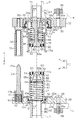
以下、本発明に係る管継手の固定構造の一実施形態について図1~図4(a)(b)を参照して説明する。図1に示されるように、管継手10は、第1継手としての雄型継手21を有する雄部材20と、該雄型継手21が軸線方向Aに沿って差し込まれることで該雄型継手21と連結される第2継手としての雌型継手31を有する雌部材30とによって構成される。
雄部材20を構成する矩形平板状の雄側基体22は、ポリアミドで形成されており、その長手方向に沿って2つの雄型継手21が所定の間隔で固設されている。また、雄側基体22には、それら2つの雄型継手21を長手方向で挟むように略円柱形状をなした2つのガイドピン23が立設されている。雄側基体22には、雄型継手21及びガイドピン23を取り囲むように四角筒状の防御壁24が固設されている。雄側基体22の各隅部には、図示しない貫通孔が穿設されており、この貫通孔には第1対象物としてのブラケット5に雄部材20を固定する際に用いられる第1固定部材25(以下では単に固定部材25という。)が裏面22bから突出するように貫挿されている。
一方、雌部材30を構成する矩形平板状の雌側基体32は、ポリアミドで形成されており、その長手方向に沿って2つの雌型継手31が雄型継手21と同じ間隔で固設されている。また、雌側基体32には、これら2つの雌型継手31を長手方向で挟むように略円筒形状をなした2つのガイド部材33が立設されている。ガイド部材33は、雄部材20に形成された2つのガイドピン23の各々に対応する位置に立設されており、該ガイドピン23が挿通可能なガイド孔34が形成されている。また雌側基体32の各隅部には、図示しない貫通孔が穿設されており、この貫通孔には、第2対象物としてのブラケット6に雌部材30を固定する際に用いられる第2固定部材35(以下では単に固定部材35という。)が裏面32bから突出するように貫挿されている。
雄部材20と雌部材30とを連結する際には、ガイド部材33のガイド孔34に各ガイドピン23が進入するように雄部材20と雌部材30とを軸線方向Aで対向させる。そして、ブラケット5を軸線方向Aに沿って移動させて雄部材20と雌部材30とを近づけると、各雄型継手21は、ガイド孔34に進入したガイドピン23によって案内されながら雌型継手31に差し込まれる。なお、連結状態においては、雄型継手21と雌型継手31とが防御壁24によって取り囲まれた状態となる。
ちなみに、本実施形態において、上述した管継手10は、電気自動車のバッテリーを冷却する冷却システムに用いられる。この冷却システムにおいては、車体側に配設された冷却装置で冷却される冷却水を車体とバッテリーとの間で循環させている。電気自動車では車体の底部にバッテリーが着脱可能に搭載されているため、例えば、雄部材20は、バッテリー側に設けられたブラケット5に固定され、雌部材30は、車体側に設けられたブラケット6に固定される。
ブラケット5には、固定部材25が嵌入される図示しない貫通孔に加えて、後述する雄型継手21の接続部46が挿入される挿入口5aが形成されており、雄部材20は、その挿入口5aに接続部46を挿入した状態でブラケット5に固定される。同様に、ブラケット6には、固定部材35が嵌入される図示しない貫通孔に加えて、後述する雌型継手31の接続部71が挿入される挿入口6aが形成されており、雌部材30は、その挿入口に接続部71を挿入した状態でブラケット6に固定される。そして、本実施形態では、雄型継手21の接続部46には、バッテリー側で固設された配管部材であって、例えばゴムホースといった可撓性を有する第1配管としての配管部材7が、その長さに余裕を持たせた状態で接続される。また、雌型継手31の接続部71には、車体に固設された配管部材であって、例えばゴムホースといった可撓性を有する第2配管としての配管部材8が、その長さに余裕を持たせた状態で接続される。
(雄部材20)
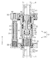
図2に示されるように、雄側基体22には、取り付け座22cによって裏面22b側で縮径された多段円柱形状の取り付け孔41を貫挿するように雄型継手21が配設されている。雄型継手21は、外部の配管が接続される雄側接続体42と、雄側接続体42に支持される雄側筒体43とを備えている。
(雄部材20)
図2に示されるように、雄側基体22には、取り付け座22cによって裏面22b側で縮径された多段円柱形状の取り付け孔41を貫挿するように雄型継手21が配設されている。雄型継手21は、外部の配管が接続される雄側接続体42と、雄側接続体42に支持される雄側筒体43とを備えている。
雄側接続体42は、ポリアミドで形成されており、内側に流路44が形成されて軸線方向Aに沿って延びる多段円筒形状をなして、その中心軸が取り付け孔41の中心軸と一致するように配設されている。雄側接続体42は、取り付け孔41内に配設されて取り付け座22cに係合する係合部45と、係合部45よりも小さな外径で形成されて雄側基体22の裏面22bから突出する接続部46とが一体形成されている。
雄側筒体43は、ポリアミドで形成されており、雄側接続体42の接続部46の内径よりも大きく且つ係合部45の内径よりも小さい外径を有して軸線方向Aに沿って延びる略円筒形状をなしている。雄側筒体43は、その中心軸が取り付け孔41の中心軸と一致するように、その一端が雄側接続体42の係合部45の内側に遊嵌された状態で配設されており、その内側に雄側接続体42の流路44に連通する流路47が形成されている。
雄側筒体43の下端には、雄側接続体42の係合部45の外径と略等しい外径を有して、取り付け孔41内に配設される鍔部43aが形成されている。雄側筒体43は、鍔部43aが雄側接続体42の係合部45に当接することにより雄側接続体42に支持される。また雄側筒体43の外周面と雄側接続体42の係合部45の内周面とがなす隙間には、当該隙間を通じて内部の流体が漏出しないように環状のシール部材49が配設されている。
そして、雄型継手21は、雄側接続体42の係合部45と雄側筒体43の鍔部43aとが取り付け孔41内に配設された状態で、該鍔部43aを覆う固定板50が図示しないねじによって雄側基体22の表面22aに螺着されることによって雄側基体22に対して固定されている。
一方、雄側筒体43の上端には、雌型継手31に差し込まれて後述する雌側弁体84を押圧面51aで押圧する雄側押圧部51が形成されている。雄側押圧部51においては、雄側弁座52によって雄側筒体43の流路47よりも小さな径を有する雄側弁孔53が押圧面51aで開口しているとともに、外周面の全周にわたって凹設された溝部に環状のシール部材54が装着されている。
また、雄側筒体43内には、雄側筒体43の内部を軸線方向Aに沿って摺動可能な雄側弁体55が配設されている。雄側弁体55は、ポリアミドで形成された略有蓋円筒形状をなしており、その中心軸が雄側筒体43の中心軸と一致するように配設されているとともに、雄側接続体42に下端が支持されたコイルばね56によって雄側弁孔53に向けて付勢されている。
雄側弁体55は、雄側筒体43の内径よりも僅かに小さい外径を有する基端部55aと、該基端部55aよりも小さな外径であって雄側弁孔53を塞ぐかたちの先端部55bとが一体形成されている。雄側弁体55は、基端部55aが雄側弁座52に当接することにより、先端部55bの端面が雄側押圧部51の押圧面51aと面一にある位置で雄側弁孔53側への変位が規制されている。基端部55aの周壁には、コイルばね56の付勢力に抗して雄側弁体55が雄側接続体42側へと変位したときに、雄側弁孔53と雄側接続体42の流路44とを連通させる連通孔55cが穿設されている。また先端部55bの外周面に形成された溝部には、雄側弁体55と雄側押圧部51との隙間を通じて雄型継手21内の流体が漏出することを抑える環状のシール部材57が装着されている。
また、雄側基体22には、雄型継手21の左側方にガイドピン23が配設されている。ガイドピン23は、軸線方向Aに沿って延びる略円柱形状をなしており、先端部23aが上方に向けて徐々に縮径されている。ガイドピン23のうち、下方に向けて拡径した部位である基端部23bは、ケース体61内に配設されている。ケース体61は、軸線方向Aに沿って延びる略円筒形状をなしてガイドピン23の基端部23bを収容している。ケース体61は、ガイドピン23の基端部23bが軸線方向Aに沿って摺動可能な内径を有しており、雄側基体22の表面22aに凹設された凹部62に嵌入されて雄側基体22に着脱可能に固定されている。ケース体61は、該ケース体61の頂部における開口が狭窄されており、ガイドピン23の基端部23bがケース体61の内側から該頂部に当接することによって、雄側基体22から離間する方向へのガイドピン23の変位を規制する。
ケース体61内には、凹部62の底面に下端が支持された弾性部材としてのコイルばね63が配設されている。コイルばね63は、軸線方向Aに沿ってガイドピン23を雄側基体22から離間させるように付勢している。すなわち、ガイドピン23は、コイルばね63の付勢力に基づく変位がケース体61の頂部に規制される位置と、コイルばね63が最も縮んだ位置との間で軸線方向Aに沿って変位する。
こうした構成の雄部材20は、雄側基体22の各隅部を貫挿させた4つの固定部材25によってブラケット5に固定されている。固定部材25は、雄側基体22及びブラケット5を貫挿させるのに十分な長さを有したボルトであって、軸線方向Aに沿うように配設されている。また、固定部材25は、これら4つの固定部材25の剪断強さの合計が雄側筒体43の剪断強さよりも小さくなるように、その材質及び断面積が選定されたものであって、例えば炭素鋼からなるM6のボルトである。ブラケット5に雄部材20を固定する際には、ブラケット5の挿入口5aに接続部46を挿入した状態で位置あわせが行われて、雄側基体22及びブラケット5に穿設された貫通孔に各固定部材25が表面22a側から嵌入される。そして、ブラケット5から突出した固定部材25の先端部にナット58が螺着されて、例えばトルクレンチ等を用いて、固定部材25の材質や大きさに応じた所定のトルクに締め付けられる。また、固定部材25には、雄側基体22とブラケット5との境目付近に、その全周にわたって凹設された切り欠き部によって、固定部材25のうちで最も剪断強さが小さくなる薄肉部25aが形成されている。
(雌部材30)
図2に示されるように、雌側基体32には、取り付け座32cによって裏面32b側で縮径された多段円柱形状の取り付け孔66を貫挿するように雌型継手31が配設されている。雌型継手31は、外部の配管が接続される雌側接続体67と、雌側接続体67に支持される雌側筒体68とを備えている。
(雌部材30)
図2に示されるように、雌側基体32には、取り付け座32cによって裏面32b側で縮径された多段円柱形状の取り付け孔66を貫挿するように雌型継手31が配設されている。雌型継手31は、外部の配管が接続される雌側接続体67と、雌側接続体67に支持される雌側筒体68とを備えている。
雌側接続体67は、ポリアミドで形成されており、内側に流路69が形成されて軸線方向Aに沿って延びる多段円筒形状をなして、その中心軸が取り付け孔66の中心軸と一致するように配設されている。雌側接続体67は、取り付け孔66内に配設されて取り付け座32cに係合する係合部70と、係合部70よりも小さな外径で形成されて雌側基体32の裏面32bから突出する接続部71とが一体形成されている。
雌側筒体68は、ポリアミドで形成されており、雌側接続体67の接続部71の内径よりも大きい内径を有して軸線方向Aに沿って延びる多段円筒形状をなしている。雌側筒体68は、その内側に流路72が形成されているとともに、その中心軸が取り付け孔66の中心軸と一致するように配設されている。雌側筒体68は、取り付け孔66内に基端部が配設される大径部73と、大径部73の先端部に段差部74を介して連結された小径部75とが一体形成されている。小径部75は、雄側筒体43が摺動可能な大きさに形成されており、その先端部には外側に拡開されて雄側筒体43が差し込まれる差込口を形成する差込部75aが形成されている。
大径部73の基端部には、大径部73の外径よりも大きく且つ雌側接続体67の係合部70の内径よりも僅かに小さい外径で形成され、該係合部70に嵌入される嵌入部73aが形成されている。雄側筒体43は、この嵌入部73aが係合部70に嵌入されることにより雌側接続体67に支持される。また嵌入部73aの外周面に形成された溝部には、嵌入部73aと雌側接続体67の係合部70との隙間を通じて雌型継手31内の流体が漏出しないように環状のシール部材76が配設されている。
そして、雌型継手31は、雌側接続体67の係合部70と大径部73の嵌入部73aとが取り付け孔66内に配設された状態で、該嵌入部73aを覆う固定板77が図示しないねじで雌側基体32の表面32aに螺着されることによって雌側基体32に対して固定されている。
また、雌側筒体68内には、雄側弁体55を押圧する弁押体80が配設されている。弁押体80は、ポリアミドで形成されており、その一端には、120°間隔で放射状に延出された3つの固定部80aが形成されている。弁押体80は、固定部80aの先端が雌側接続体67と雌側筒体68とに挟持されることによって雌側筒体68内に固定されている。弁押体80には、3つの固定部80aの中心部から差込部75a側へ向けて略円柱形状の延出部80bが延出形成されている。
延出部80bの外周面には、3つの固定部80aの間に向けて軸線方向Aに沿って凹設され、雌側接続体67の流路69と雌側筒体68の流路72とを連通させる連通路81が形成されている。
延出部80bの先端には、略円柱形状の雌側押圧部82が形成されている。雌側押圧部82は、中心軸が取り付け孔66の中心軸と一致するように配設されており、延出部80bの径よりも大きな径であって、且つ雄側弁孔53に挿通可能な外径で形成されている。雌側押圧部82の外周面に形成された溝部には、環状のシール部材83が装着されている。
また、雌側筒体68内には、雌側押圧部82と雌側筒体68との間の環状の隙間を塞ぐかたちをなす雌側弁体84が配設されている。雌側弁体84は、ポリアミドで形成された軸線方向Aに沿って延びる略円筒形状をなして、中心軸が取り付け孔66の中心軸と一致するように配設されている。雌側弁体84は、雌側押圧部82の外周面を摺動可能な内径と、雌側筒体68の小径部75を摺動可能な外径とを有する略円筒形状に形成されている。雌側弁体84の外周面に形成された溝部には、雌側弁体84と雌側筒体68との隙間を通じて雌型継手31内の流体が漏出することを抑える環状のシール部材85が装着されている。なお、雌側押圧部82に装着されたシール部材85は、雌側押圧部82と雌側弁体84との隙間を通じて雌型継手31内の流体が漏出することを抑える。
雌側弁体84は、弁押体80の固定部80aに一端が支持されたコイルばね86によって差込部75a側へ付勢されている。雌側弁体84には、雌側接続体67側の端部における外周面に鍔部84aが突設されている。この鍔部84aは、雌側筒体68の段差部74に当接することにより、雌側弁体84の端面が雌側押圧部82の押圧面82aと面一になる位置で雌側弁体84の差込部75a側への変位を規制する。
雌側基体32における雌型継手31の左側には、ガイド部材33が配設されている。ガイド部材33は、軸線方向Aに沿って延びる有底円筒形状をなしており、底部から延出形成されたねじ部89によって雌側基体32に螺着されている。ガイド部材33には、その端面に開口を有して軸線方向Aに沿って延びるガイド孔34が形成されている。ガイド孔34は、ガイドピン23の外径よりも大きな径で形成されているとともにガイドピン23を収容可能な長さに形成されている。
こうした構成の雌部材30は、雌側基体32の各隅部を貫挿させた4つの固定部材35によってブラケット6に固定されている。固定部材35は、雌側基体32及びブラケット6を貫挿させるのに十分な長さを有したボルトであって、軸線方向Aに沿うように配設されている。また、固定部材35は、これら4つの固定部材35の剪断強さの合計が雌側筒体68の剪断強さよりも小さくなるように、その材質及び大きさが選定されたものである。ブラケット6に雌部材30を固定する際には、ブラケット6の挿入口6aに接続部71を挿入した状態で位置あわせが行われて、雌側基体32及びブラケット6に穿設された貫通孔に固定部材35が表面32a側から嵌入される。そして、ブラケット6から突出した固定部材35の先端部にナット90が螺着されて、例えばトルクレンチ等を用いて、固定部材35の材質や大きさに応じた所定のトルクに締め付けられる。また、固定部材35には、雌側基体32とブラケット6との境目付近に、その全周にわたって凹設された切り欠きによって、固定部材35のうちで最も剪断強さが小さな薄肉部35aが形成されている。
上述した雄型継手21を有する雄部材20と、雌型継手31を有する雌部材30とで構成される管継手10の作用について図3を参照して説明する。
まず、ガイドピン23がガイド孔34に進入するように軸線方向Aに沿って雄部材20と雌部材30とが配置される。そして、雄部材20と雌部材30とが近づけられると、雄型継手21は、ガイド孔34に進入したガイドピン23に案内されながら雌型継手31に差し込まれる。雌型継手31に雄型継手21が差し込まれると、雄側筒体43が雌側筒体68の小径部75を摺動し、やがて雄側押圧部51と雌側弁体84とが当接するとともに雄側弁体55と雌側押圧部82とが当接する。
まず、ガイドピン23がガイド孔34に進入するように軸線方向Aに沿って雄部材20と雌部材30とが配置される。そして、雄部材20と雌部材30とが近づけられると、雄型継手21は、ガイド孔34に進入したガイドピン23に案内されながら雌型継手31に差し込まれる。雌型継手31に雄型継手21が差し込まれると、雄側筒体43が雌側筒体68の小径部75を摺動し、やがて雄側押圧部51と雌側弁体84とが当接するとともに雄側弁体55と雌側押圧部82とが当接する。
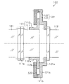
この状態から、さらに雌型継手31に雄型継手21が差し込まれると、図3に示されるように、雄側押圧部51が、コイルばね86の付勢力に抗して雌側弁体84を押圧し、雌側弁体84を雌側接続体67側へと変位させる。また雌側押圧部82が、コイルばね56の付勢力に抗して雄側弁体55を押圧し、雄側弁体55が雄側接続体42側へと変位する。こうした連結状態においては、雄側接続体42の流路44と雌側接続体67の流路69とが互いに連通して流体の流通が可能となる。なお、連結状態においては、雄側押圧部51の外周面に装着されたシール部材54は、雄側筒体43の外周面と雌側筒体68の内周面との隙間を通じて流体が漏出することを抑える。
また、上述した雄部材20及び雌部材30においては、雄側筒体43の剪断強さよりも4つの固定部材25の剪断強さの合計が小さく、且つ雌側筒体68の剪断強さよりも4つの固定部材35の剪断強さが小さい。すなわち、雌側筒体68と、該雌側筒体68に差し込まれた雄側筒体43とによって構成される雄型継手21と雌型継手31との連結部分91は、これら固定部材25,35の剪断強さの合計よりも大きいことになる。
(作用)
次に、上述した雄部材20及び雌部材30のブラケット5,6への固定構造の作用の一例について図4(a)(b)を参照して説明する。なお、図4(a)(b)においては、防御壁24、ガイドピン23、ガイド部材33を省略して示しているとともに、雄側基体22とブラケット5との固定部分、及び雌側基体32とブラケット6との固定部分については断面構造を示している。また、上述したように、本実施形態において管継手10は、電気自動車に着脱可能に搭載されたバッテリーを冷却する冷却システムに用いられており、雄部材20はバッテリー側のブラケット5に固定されて、雌部材30は車体側のブラケット6に固定されている。
(作用)
次に、上述した雄部材20及び雌部材30のブラケット5,6への固定構造の作用の一例について図4(a)(b)を参照して説明する。なお、図4(a)(b)においては、防御壁24、ガイドピン23、ガイド部材33を省略して示しているとともに、雄側基体22とブラケット5との固定部分、及び雌側基体32とブラケット6との固定部分については断面構造を示している。また、上述したように、本実施形態において管継手10は、電気自動車に着脱可能に搭載されたバッテリーを冷却する冷却システムに用いられており、雄部材20はバッテリー側のブラケット5に固定されて、雌部材30は車体側のブラケット6に固定されている。
図4(a)に示されるように、例えばこれら管継手10を備えた電気自動車に後続の自動車が追突したりすると、バッテリー(ブラケット5)に対して軸線方向Aに直交する方向へ移動させようとする荷重Fが作用する。この荷重Fは、雄部材20の各固定部材25、雄型継手21と雌型継手31との連結部分91、雌部材30の各固定部材35の各々に作用する。このとき、固定部材25において雄側基体22とブラケット6との境目に位置している薄肉部25aには、ブラケット5から受ける荷重Fに基づく剪断力が生じている。
そして、ブラケット5に作用する荷重Fが連結部分91を変形させるような大きさである場合には、固定部材25の合計の剪断強さが連結部分91における剪断強さよりも小さいことから、図4(b)に示すように、固定部材25は、連結部分91が変形するよりも前に上述した剪断力によって薄肉部25aで剪断することになる。すなわち、固定部材25による雄部材20の固定が解除されることから、軸線方向Aに直交する方向にブラケット5が移動したとしても、雄型継手21と雌型継手31との連結部分91に作用する荷重が大幅に低減されてその連結状態が維持されやすくなる。
なお、固定部材25は、薄肉部25aを基準として雄側基体22側の部位とブラケット5側の部位とに分断されることになるが、例えば雄側基体22側の部位が裏面22bから突出してしまったとしても、その突出量は僅かでありブラケット5の移動を妨げるようなものではない。
また、こうしたブラケット5の移動、すなわちバッテリーの移動によって、当該バッテリーにおける配管部材7の固設部分も移動することになる。これに対して本実施形態では、配管部材7が可撓性を有し且つその長さに余裕があることから、バッテリーの移動によって配管部材7の固設部分と雄型継手21の接続部46との位置関係が変化したとしても、その変化に応じて配管部材7が追従することになる。
なお、上述した作用の記載では、ブラケット5に荷重Fが作用したときに雄部材20の固定部材25が剪断する例について説明したが、雄部材20の固定部材25に加えて雌部材30の固定部材35までも剪断する場合もあるし、雌部材30の固定部材35のみが剪断する場合もある。しかし、いずれの場合もブラケット5とブラケット6との相対位置が変化しても、雄型継手21と雌型継手31とを連結状態に維持することが可能である。
以上説明したように、上記実施形態に係る管継手10の固定構造によれば、以下列記するような効果が得られるようになる。
(1)固定部材25,35の剪断強さの合計が雄型継手21と雌型継手31との連結部分91における剪断強さよりも小さいことから、該連結部分91を変形させるような荷重Fがブラケット5に作用したとしても、その連結部分91が変形するより前に固定部材25,35の少なくとも一方が剪断することになる。上記実施形態のように、固定部材25が剪断すると、ブラケット5に対する雄部材20の固定が解除される。
(1)固定部材25,35の剪断強さの合計が雄型継手21と雌型継手31との連結部分91における剪断強さよりも小さいことから、該連結部分91を変形させるような荷重Fがブラケット5に作用したとしても、その連結部分91が変形するより前に固定部材25,35の少なくとも一方が剪断することになる。上記実施形態のように、固定部材25が剪断すると、ブラケット5に対する雄部材20の固定が解除される。
この際、雄型継手21の接続部46には、可撓性を有する配管部材7が接続されていることから、ブラケット5の移動によって配管部材7の固設部分と雄型継手21の接続部46との位置関係が変化したとしても、その変化に応じて配管部材7を追従させることができる。それゆえに、雄型継手21と雌型継手31との連結部分91に作用する荷重が大幅に低減されることから、雄型継手21と雌型継手31との連結状態が維持されやすくなるとともに管継手10の保護性を高めることができる。
(2)雄部材20及び雌部材30は、軸線方向Aに沿うように配設されたボルトである固定部材25,35によってブラケット5,6に固定されている。すなわち、固定部材25,35は、雄型継手21を雌型継手31に差し込む軸線方向Aに直交する方向の荷重Fに対する剪断強さが最も小さくなるように配設されている。その結果、該荷重Fによって固定部材25,35が剪断されやすくなることから、軸線方向Aと交差する方向の荷重、特に軸線方向Aと直交する方向の荷重に対して、管継手10の保護性を高めることができる。
(3)ブラケット5に荷重Fが作用すると、固定部材25における雄側基体22とブラケット5との境目付近の部位には、その荷重Fに基づく剪断力が生じる。上記固定部材25には、その部位に最も剪断強さが小さくなる薄肉部25aが形成されている。これにより、固定部材25を薄肉部25aで剪断させることができる。その結果、こうした薄肉部25aが設けられていない固定部材を用いた場合に比べて、すなわち固定部材25のどの部位が剪断するか特定されない場合に比べて、剪断後の固定部材25がブラケット5の移動を妨げることを抑えることができる。また、雄部材20の固定がより小さな荷重で解除されることから、雄型継手21と雌型継手31との連結部分91への機械的な負荷を高い確実性のもとで低減することもできる。
(4)固定部材25の剪断強さの合計及び固定部材35の剪断強さの合計の各々が連結部分91の剪断強さよりも小さいことから、これら固定部材25,35に互いに異なる大きさの剪断力が作用したとしても、よい大きな剪断力が作用する固定部材が剪断される。その結果、より高い確実性のもとで、連結状態にある管継手10の保護性を高めることができる。
(5)固定部材25が剪断することによって雄部材20の固定が解除されることから、当該雄部材20を再使用する際には、固定部材25を取替えるだけで済む。なお、雌部材30についても同様のことがいえる。
なお、上記実施の形態は、以下のような態様をもって実施することもできる。
雄部材20及び雌部材30の各々は、筒体43,68よりも小さな剪断強さを有する固定部材25,35によってブラケット5,6に固定されている。これを変更して、雄部材20及び雌部材30のいずれか一方が、上述した固定部材で固定されていてもよい。すなわち、例えば、雄側筒体43の剪断強さよりも小さい剪断強さを有する固定部材によって雄側基体22が固定され、雌側筒体68の剪断強さよりも大きい剪断強さを有する固定部材によって雌側基体32が固定されてもよい。こうした構成の下においては、雌部材30が固定されたブラケット6に荷重Fが作用した場合、雄部材20を固定する固定部材25が剪断してブラケット5に対する雄部材20の固定が解除され、連結状態にある管継手10はブラケット6とともに移動することになる。
雄部材20及び雌部材30の各々は、筒体43,68よりも小さな剪断強さを有する固定部材25,35によってブラケット5,6に固定されている。これを変更して、雄部材20及び雌部材30のいずれか一方が、上述した固定部材で固定されていてもよい。すなわち、例えば、雄側筒体43の剪断強さよりも小さい剪断強さを有する固定部材によって雄側基体22が固定され、雌側筒体68の剪断強さよりも大きい剪断強さを有する固定部材によって雌側基体32が固定されてもよい。こうした構成の下においては、雌部材30が固定されたブラケット6に荷重Fが作用した場合、雄部材20を固定する固定部材25が剪断してブラケット5に対する雄部材20の固定が解除され、連結状態にある管継手10はブラケット6とともに移動することになる。
薄肉部25a、35aの形成される部位は、雄側基体22とブラケット5との境目付近の部位以外であってもよい。また薄肉部25a、35aは、割愛されてもよい。要は、固定部材の剪断強さが連結部分よりも小さい構成であればよい。
固定部材25は、その長手方向が軸線方向Aに沿って配設されている態様に限らず、軸線方向Aに直交する方向の荷重に対する剪断強さが雄側筒体43の剪断強さよりも小さいならば、例えば軸線方向Aに交差する方向に沿って配設されていてもよい。すなわち、例えばブラケット5の移動が想定される方向に応じて固定部材25の延出方向を適宜変更するとよい。なお、固定部材35に対しても同様のことがいえる。
固定部材の剪断強さが連結部分の剪断強さよりも大きい構成であってもよく、要は、固定部材における剪断強さ、圧縮強さ、及び引っ張り強さの少なくとも一つ、すなわち破壊応力が連結部分よりも小さい構成であればよい。このような構成であれば、固定構造に作用する剪断応力、圧縮応力、引っ張り応力の少なくとも一つに対し、連結状態の管継手に対し保護性を高めることが可能である。
雄部材20及び雌部材30には、それぞれ可撓性を有した配管部材7,8がそれぞれ接続されている。これを変更して、例えば、雄側筒体43の剪断強さよりも小さい剪断強さを有する固定部材によって雄側基体22が固定され、雌側筒体68の剪断強さよりも大きい剪断強さを有する固定部材によって雌側基体32が固定されている場合には、雄型継手21のみに可撓性を有した配管部材7が接続されていてもよい。
こうした構成の下では、雌部材30が固定されたブラケット6に荷重Fが作用すると、雄部材20を固定する固定部材25が剪断してブラケット5に対する雄部材20の固定が解除される。そして、連結状態にある管継手10はブラケット6にとともに移動する。
このとき、雄型継手21の接続部46に非可撓性の配管部材が接続されているとなれば、ブラケット6に追従した管継手10の移動がその配管部材によって妨げられるばかりか、連結部分91に機械的な負荷が作用することになる。この点、上述した構成によれば、雄部材20の固定解除後、ブラケット6とともに移動する管継手10に配管部材7を追従させることができる。すなわち、筒体よりも剪断強さが小さい固定部材によって固定された継手に対して、可撓性を有する配管部材が接続されていればよい。
雄側筒体43等、雄型継手21に関わる部材の材質は、ポリアミドに限られるものではない。また、雌側筒体68等、雌型継手31に関わる部材の材質も、ポリアミドに限られるものではない。
また、固定部材は、雄型継手21と雌型継手31との連結部分91よりも破壊応力が小さいものであればよく、炭素鋼からなるボルトに限らず、樹脂製のボルトであってもよい。また、樹脂製のアンカークリップやカヌークリップ、ブラッシュクリップ等のクリップ類、ターンファスナー等のファスナー類であってもよい。
また、雄部材20の固定部材は、例えば、雄側基体22の裏面22bから立設された取り付けピンと、取り付けピンが嵌入される嵌入部を有してブラケット5に対して直接あるいは間接的に固定されるボスとによって構成されてもよい。こうした構成においては、雄型継手21と雌型継手31との連結部分91に比較して、取り付けピンの剪断強さを大きく且つボスの剪断強さを小さくしてもよいし、取り付けピンの剪断強さを小さく且つボスの剪断強さを大きくしてもよいし、双方の剪断強さが小さくてもよい。こうした構成によれば、取り付けピン及びボスのいずれか一方が剪断することによって、ブラケット5に対する雄部材20の固定を解除することが可能である。なお、雌部材30についても同様である。
雄部材20及び雌部材30が固定される対象物は、各々に配設された配管部材が雄部材20と雌部材30とによって互いに接続されるものであればよく、電気自動車を構成する車体及びバッテリーに限られるものではない。
雄部材20に固設される雄型継手21、及び雌部材30に固設される雌型継手31の数は、適宜変更可能である。
なお、2011年6月20日に出願された日本特許出願第2011-136120号の明細書、特許請求の範囲、図面及び要約書の全内容をここに引用し、本発明の明細書の開示として、取り入れるものである。
なお、2011年6月20日に出願された日本特許出願第2011-136120号の明細書、特許請求の範囲、図面及び要約書の全内容をここに引用し、本発明の明細書の開示として、取り入れるものである。
Claims (5)
- 互いに連結可能な第1継手と第2継手とから構成される管継手のうち、
第1対象物の第1配管に連結された前記第1継手が、前記第1対象物に固定され、
第2対象物の第2配管に連結された前記第2継手が、前記第2対象物に固定されてなる管継手の固定構造であって、
前記第1対象物に対し前記第1継手を固定する第1固定部材を備え、
前記第1配管が、可撓性を有した配管であり、
前記第1固定部材の破壊応力が、前記第1継手と前記第2継手との連結部分の破壊応力よりも小さい
ことを特徴とする管継手の固定構造。 - 前記第1継手と前記第2継手との連結する方向と交差する方向では、
前記第1固定部材の剪断強さが、前記第1継手と前記第2継手との連結部分の剪断強さよりも小さい
請求項1に記載の管継手の固定構造。 - 前記第1固定部材が、
前記第1継手と前記第2継手との連結する方向に延びる部材である
請求項2に記載の管継手の固定構造。 - 前記第1固定部材は、前記第1継手と前記第1対象物との境目と対向する部位に切り欠きを有する
請求項3に記載の管継手の固定構造。 - 前記第2対象物に対し前記第2継手を固定する第2固定部材を備え、
前記第2配管が、可撓性を有した配管であり、
前記第2固定部材の破壊応力が、前記第1継手と前記第2継手との連結部分の破壊応力よりも小さい
請求項1~4のいずれか一項に記載の管継手の固定構造。
Applications Claiming Priority (2)
| Application Number | Priority Date | Filing Date | Title |
|---|---|---|---|
| JP2011-136120 | 2011-06-20 | ||
| JP2011136120A JP2013002585A (ja) | 2011-06-20 | 2011-06-20 | 管継手の固定構造 |
Publications (1)
| Publication Number | Publication Date |
|---|---|
| WO2012176673A1 true WO2012176673A1 (ja) | 2012-12-27 |
Family
ID=47422513
Family Applications (1)
| Application Number | Title | Priority Date | Filing Date |
|---|---|---|---|
| PCT/JP2012/065157 Ceased WO2012176673A1 (ja) | 2011-06-20 | 2012-06-13 | 管継手の固定構造 |
Country Status (2)
| Country | Link |
|---|---|
| JP (1) | JP2013002585A (ja) |
| WO (1) | WO2012176673A1 (ja) |
Cited By (1)
| Publication number | Priority date | Publication date | Assignee | Title |
|---|---|---|---|---|
| US20200300398A1 (en) * | 2019-03-22 | 2020-09-24 | Airbus Operations Gmbh | Multipurpose connector for an aircraft monument and aircraft monument, aircraft area and aircraft having a multipurpose connector |
Citations (3)
| Publication number | Priority date | Publication date | Assignee | Title |
|---|---|---|---|---|
| JPS5629154B2 (ja) * | 1974-07-18 | 1981-07-06 | ||
| JPH0126764B2 (ja) * | 1984-06-29 | 1989-05-25 | Yokohama Eirokuitsupu Kk | |
| JP2003035389A (ja) * | 2001-07-23 | 2003-02-07 | Honda Motor Co Ltd | ソケット着脱治具 |
-
2011
- 2011-06-20 JP JP2011136120A patent/JP2013002585A/ja not_active Withdrawn
-
2012
- 2012-06-13 WO PCT/JP2012/065157 patent/WO2012176673A1/ja not_active Ceased
Patent Citations (3)
| Publication number | Priority date | Publication date | Assignee | Title |
|---|---|---|---|---|
| JPS5629154B2 (ja) * | 1974-07-18 | 1981-07-06 | ||
| JPH0126764B2 (ja) * | 1984-06-29 | 1989-05-25 | Yokohama Eirokuitsupu Kk | |
| JP2003035389A (ja) * | 2001-07-23 | 2003-02-07 | Honda Motor Co Ltd | ソケット着脱治具 |
Cited By (2)
| Publication number | Priority date | Publication date | Assignee | Title |
|---|---|---|---|---|
| US20200300398A1 (en) * | 2019-03-22 | 2020-09-24 | Airbus Operations Gmbh | Multipurpose connector for an aircraft monument and aircraft monument, aircraft area and aircraft having a multipurpose connector |
| US11927290B2 (en) * | 2019-03-22 | 2024-03-12 | Airbus Operations Gmbh | Multipurpose connector for an aircraft monument and aircraft monument, aircraft area and aircraft having a multipurpose connector |
Also Published As
| Publication number | Publication date |
|---|---|
| JP2013002585A (ja) | 2013-01-07 |
Similar Documents
| Publication | Publication Date | Title |
|---|---|---|
| EP2833037B1 (en) | Valve unit | |
| US9046182B2 (en) | Check valve | |
| US6883550B2 (en) | Flexible pipe joint | |
| US9791061B2 (en) | Valve | |
| JP6374250B2 (ja) | 接合部の補強治具 | |
| JP4190502B2 (ja) | 管接続構造 | |
| JP6259357B2 (ja) | 配管接続構造及び接続部材 | |
| US20160258560A1 (en) | Joint for high-pressure pipes and joint structure | |
| US20150101174A1 (en) | Aircraft washer | |
| US20200347940A1 (en) | Valve cartridge assembly | |
| KR20180096464A (ko) | 임의의 방향과 각도로 배관 연결이 가능한 배관용 연결구 | |
| WO2012066728A1 (ja) | コネクタ装置 | |
| US9228687B2 (en) | Water hammer arrester | |
| US20190293179A1 (en) | Seal structure, sealing method, and coupling equipped with said seal structure | |
| JP5192979B2 (ja) | 管継手構造 | |
| US20110232779A1 (en) | Excess flow safety shut-off valve | |
| US9038668B2 (en) | Accumulator assembly | |
| CN102648373B (zh) | 检验销 | |
| WO2012176673A1 (ja) | 管継手の固定構造 | |
| JP2015025525A (ja) | 管体の接続構造 | |
| US20100207047A1 (en) | Gas shutoff valve | |
| CN105408618B (zh) | 将阀夹持在泵上的结构 | |
| KR101638835B1 (ko) | 파이프 연결구 | |
| KR20250050090A (ko) | 커넥터 디바이스 | |
| KR101693894B1 (ko) | 퀵커넥터 체결 확인장치 |
Legal Events
| Date | Code | Title | Description |
|---|---|---|---|
| 121 | Ep: the epo has been informed by wipo that ep was designated in this application |
Ref document number: 12802945 Country of ref document: EP Kind code of ref document: A1 |
|
| NENP | Non-entry into the national phase |
Ref country code: DE |
|
| 122 | Ep: pct application non-entry in european phase |
Ref document number: 12802945 Country of ref document: EP Kind code of ref document: A1 |