WO2012176628A1 - Imaging device and wireless system - Google Patents
Imaging device and wireless system Download PDFInfo
- Publication number
- WO2012176628A1 WO2012176628A1 PCT/JP2012/064750 JP2012064750W WO2012176628A1 WO 2012176628 A1 WO2012176628 A1 WO 2012176628A1 JP 2012064750 W JP2012064750 W JP 2012064750W WO 2012176628 A1 WO2012176628 A1 WO 2012176628A1
- Authority
- WO
- WIPO (PCT)
- Prior art keywords
- unit
- wireless
- antenna
- wireless terminal
- identification information
- Prior art date
Links
Images


Classifications
-
- G—PHYSICS
- G06—COMPUTING; CALCULATING OR COUNTING
- G06F—ELECTRIC DIGITAL DATA PROCESSING
- G06F3/00—Input arrangements for transferring data to be processed into a form capable of being handled by the computer; Output arrangements for transferring data from processing unit to output unit, e.g. interface arrangements
- G06F3/002—Specific input/output arrangements not covered by G06F3/01 - G06F3/16
- G06F3/005—Input arrangements through a video camera
-
- H—ELECTRICITY
- H04—ELECTRIC COMMUNICATION TECHNIQUE
- H04N—PICTORIAL COMMUNICATION, e.g. TELEVISION
- H04N1/00—Scanning, transmission or reproduction of documents or the like, e.g. facsimile transmission; Details thereof
- H04N1/00127—Connection or combination of a still picture apparatus with another apparatus, e.g. for storage, processing or transmission of still picture signals or of information associated with a still picture
- H04N1/00347—Connection or combination of a still picture apparatus with another apparatus, e.g. for storage, processing or transmission of still picture signals or of information associated with a still picture with another still picture apparatus, e.g. hybrid still picture apparatus
-
- G—PHYSICS
- G01—MEASURING; TESTING
- G01S—RADIO DIRECTION-FINDING; RADIO NAVIGATION; DETERMINING DISTANCE OR VELOCITY BY USE OF RADIO WAVES; LOCATING OR PRESENCE-DETECTING BY USE OF THE REFLECTION OR RERADIATION OF RADIO WAVES; ANALOGOUS ARRANGEMENTS USING OTHER WAVES
- G01S3/00—Direction-finders for determining the direction from which infrasonic, sonic, ultrasonic, or electromagnetic waves, or particle emission, not having a directional significance, are being received
- G01S3/02—Direction-finders for determining the direction from which infrasonic, sonic, ultrasonic, or electromagnetic waves, or particle emission, not having a directional significance, are being received using radio waves
- G01S3/14—Systems for determining direction or deviation from predetermined direction
-
- H—ELECTRICITY
- H04—ELECTRIC COMMUNICATION TECHNIQUE
- H04N—PICTORIAL COMMUNICATION, e.g. TELEVISION
- H04N1/00—Scanning, transmission or reproduction of documents or the like, e.g. facsimile transmission; Details thereof
- H04N1/00127—Connection or combination of a still picture apparatus with another apparatus, e.g. for storage, processing or transmission of still picture signals or of information associated with a still picture
-
- H—ELECTRICITY
- H04—ELECTRIC COMMUNICATION TECHNIQUE
- H04N—PICTORIAL COMMUNICATION, e.g. TELEVISION
- H04N23/00—Cameras or camera modules comprising electronic image sensors; Control thereof
- H04N23/60—Control of cameras or camera modules
- H04N23/63—Control of cameras or camera modules by using electronic viewfinders
-
- H—ELECTRICITY
- H04—ELECTRIC COMMUNICATION TECHNIQUE
- H04N—PICTORIAL COMMUNICATION, e.g. TELEVISION
- H04N23/00—Cameras or camera modules comprising electronic image sensors; Control thereof
- H04N23/60—Control of cameras or camera modules
- H04N23/66—Remote control of cameras or camera parts, e.g. by remote control devices
- H04N23/661—Transmitting camera control signals through networks, e.g. control via the Internet
-
- H—ELECTRICITY
- H04—ELECTRIC COMMUNICATION TECHNIQUE
- H04N—PICTORIAL COMMUNICATION, e.g. TELEVISION
- H04N2101/00—Still video cameras
-
- H—ELECTRICITY
- H04—ELECTRIC COMMUNICATION TECHNIQUE
- H04N—PICTORIAL COMMUNICATION, e.g. TELEVISION
- H04N2201/00—Indexing scheme relating to scanning, transmission or reproduction of documents or the like, and to details thereof
- H04N2201/0008—Connection or combination of a still picture apparatus with another apparatus
- H04N2201/0015—Control of image communication with the connected apparatus, e.g. signalling capability
-
- H—ELECTRICITY
- H04—ELECTRIC COMMUNICATION TECHNIQUE
- H04N—PICTORIAL COMMUNICATION, e.g. TELEVISION
- H04N2201/00—Indexing scheme relating to scanning, transmission or reproduction of documents or the like, and to details thereof
- H04N2201/0008—Connection or combination of a still picture apparatus with another apparatus
- H04N2201/0034—Details of the connection, e.g. connector, interface
- H04N2201/0044—Connecting to a plurality of different apparatus; Using a plurality of different connectors
-
- H—ELECTRICITY
- H04—ELECTRIC COMMUNICATION TECHNIQUE
- H04N—PICTORIAL COMMUNICATION, e.g. TELEVISION
- H04N2201/00—Indexing scheme relating to scanning, transmission or reproduction of documents or the like, and to details thereof
- H04N2201/0008—Connection or combination of a still picture apparatus with another apparatus
- H04N2201/0034—Details of the connection, e.g. connector, interface
- H04N2201/0048—Type of connection
- H04N2201/0055—By radio
-
- H—ELECTRICITY
- H04—ELECTRIC COMMUNICATION TECHNIQUE
- H04N—PICTORIAL COMMUNICATION, e.g. TELEVISION
- H04N2201/00—Indexing scheme relating to scanning, transmission or reproduction of documents or the like, and to details thereof
- H04N2201/0077—Types of the still picture apparatus
- H04N2201/0084—Digital still camera
-
- H—ELECTRICITY
- H04—ELECTRIC COMMUNICATION TECHNIQUE
- H04N—PICTORIAL COMMUNICATION, e.g. TELEVISION
- H04N2201/00—Indexing scheme relating to scanning, transmission or reproduction of documents or the like, and to details thereof
- H04N2201/0077—Types of the still picture apparatus
- H04N2201/0086—Image transceiver
-
- H—ELECTRICITY
- H04—ELECTRIC COMMUNICATION TECHNIQUE
- H04N—PICTORIAL COMMUNICATION, e.g. TELEVISION
- H04N2201/00—Indexing scheme relating to scanning, transmission or reproduction of documents or the like, and to details thereof
- H04N2201/0077—Types of the still picture apparatus
- H04N2201/0089—Image display device
Landscapes
- Engineering & Computer Science (AREA)
- Multimedia (AREA)
- Signal Processing (AREA)
- Physics & Mathematics (AREA)
- General Physics & Mathematics (AREA)
- Theoretical Computer Science (AREA)
- Radar, Positioning & Navigation (AREA)
- Remote Sensing (AREA)
- Human Computer Interaction (AREA)
- General Engineering & Computer Science (AREA)
- Studio Devices (AREA)
- Mobile Radio Communication Systems (AREA)
Abstract
An imaging device having: an imaging unit that captures images; a display unit that displays the images; an antenna arranged at a predetermined position relative to the imaging unit; an antenna control unit that changes the direction of maximum gain for the antenna and controls the directionality of the antenna; a wireless unit that, via the antenna, sends search data to at least one wireless terminal, receives response data in relation to the search data, and also sends control data; a reception strength detection unit that detects the reception strength of the response data; an identification information extraction unit that extracts identification information for the wireless terminal that is the transmission source for the response data; a record control unit that performs control that generates data sets associating the identification information, the reception strength, and the direction of maximum gain; a recording unit that records the data sets; a relative angle extraction unit that extracts, as a relative angle indicating the relative direction of the wireless terminal that uses the imaging device as a reference, the direction of maximum gain for the data set having a relatively greater reception strength than others among data sets having the same identification information recorded in the recording unit; an estimated position calculation unit that calculates the estimated position of a wireless terminal in the image displayed in the display unit, on the basis of the angle of view of the display unit and the relative angle; a display control unit that causes the image to be displayed in the display unit and also causes terminal information identifying the wireless terminal corresponding to the identification information to be displayed superimposed at the estimated position; an instruction input detection unit that detects instructions from an operator relating to the wireless connection between a plurality of the wireless terminals, by detecting instructions whereby the operator selects terminal information displayed in the display unit; and a wireless connection switching control unit that performs control that transmits the control data relating to wireless connections to the at least one wireless terminal, on the basis of the operator instructions detected by the instruction input detection unit.
Description
本発明は、撮像装置、無線システムに関する。
本願は、2011年6月24日に、日本に出願された特願2011-140830号に基づき優先権を主張し、その内容をここに援用する。 The present invention relates to an imaging apparatus and a wireless system.
This application claims priority based on Japanese Patent Application No. 2011-140830 filed in Japan on June 24, 2011, the contents of which are incorporated herein by reference.
映像情報等の送受信を行う複数の無線端末間で、接続する無線端末の組み合わせを切り変えることができる無線システムがある。例えば、LCD(Liquid Crystal Display;液晶ディスプレー)パネル等の表示デバイスとタッチパネル等の入力デバイスを組み合わせたGUI(Graphical User Interface)機能を持つ撮像装置を利用して、無線端末の探索を行い、その探索結果を撮像装置の表示デバイスに表示し、タッチパネル等を介して入力される操作者の指示に基づいて、無線端末間の接続を切り替えるシステムが特許文献1に記載されている。
There is a wireless system that can switch the combination of wireless terminals to be connected between a plurality of wireless terminals that transmit and receive video information and the like. For example, a wireless terminal is searched using an imaging device having a GUI (Graphical User Interface) function that combines a display device such as an LCD (Liquid Crystal Display) panel and an input device such as a touch panel. Patent Document 1 discloses a system that displays a result on a display device of an imaging apparatus and switches connection between wireless terminals based on an operator instruction input via a touch panel or the like.
従来技術では図9に示す様に、撮像装置9aが周囲の無線端末9c-1~9c-3を探索し、発見した無線端末をLCD等の表示部9bにアイコンで示していた。しかしながら、探索により発見した順番や名称等の順番でアイコンを並べて表示する事しかできなかった。従って、実際の無線端末群9c-1~9c-3の実空間における配置と、表示部9b上のアイコンとの関連が操作者にとって直感的にわかりづらく、接続の切り替え等の指示が困難であった。
In the prior art, as shown in FIG. 9, the imaging device 9a searches for surrounding wireless terminals 9c-1 to 9c-3, and the discovered wireless terminal is indicated by an icon on a display unit 9b such as an LCD. However, it was only possible to display icons side by side in the order of discovery and the order of names. Therefore, it is difficult for the operator to intuitively understand the relationship between the actual arrangement of the wireless terminal groups 9c-1 to 9c-3 and the icons on the display unit 9b, and it is difficult to instruct connection switching. It was.
本発明は上記の点に鑑みてなされたものであり、操作者が、容易に無線端末の切り替えを行うことができる撮像装置、無線システムを提供する。
The present invention has been made in view of the above points, and provides an imaging apparatus and a wireless system in which an operator can easily switch between wireless terminals.
本発明の撮像装置は、画像を撮像する撮像部と、前記画像を表示する表示部と、前記撮像部に対して予め決められた位置に配置されるアンテナと、前記アンテナの最大利得方向を変化させて前記アンテナの指向性を制御するアンテナ制御部と、前記アンテナを経由して、1つ以上の無線端末に対して探索データを送信し、かつ、前記探索データに対する応答データを受信し、さらに制御データを送信する無線部と、前記応答データの受信強度を検出する受信強度検出部と、前記応答データの送信元である前記無線端末の識別情報を抽出する識別情報抽出部と、前記識別情報と前記受信強度と前記最大利得方向とを関連づけるデータセットを生成する制御を行う記録制御部と、前記データセットを記録する記録部と、前記記録部に記録された同一の前記識別情報を持つ前記データセットの中で前記受信強度が他の前記受信強度よりも相対的に大きい前記データセットの前記最大利得方向を、撮像装置を基準とする前記無線端末の相対的な方向を示す相対角度として抽出する相対角度抽出部と、前記表示部の画角と前記相対角度に基づいて、前記表示部に表示される前記画像上の前記無線端末の推定位置を計算する推定位置計算部と、前記表示部に、前記画像を表示させるとともに、前記識別情報に対応する前記無線端末を特定する端末情報を前記推定位置に重畳表示する様に表示させる制御を行う表示制御部と、前記表示部に表示された前記端末情報を操作者が選択する指示を検知する事で、複数の前記無線端末間での無線接続に関する操作者の指示を検知する指示入力検知部と、前記指示入力検知部が検知した前記操作者の指示に基づき、少なくとも1つ以上の前記無線端末に対して無線接続に関する前記制御データを送信する制御を行う無線接続切り替え制御部と、を有する。
An imaging apparatus according to the present invention includes an imaging unit that captures an image, a display unit that displays the image, an antenna that is disposed at a predetermined position with respect to the imaging unit, and a maximum gain direction of the antenna that changes. An antenna control unit for controlling the directivity of the antenna, and transmitting search data to one or more wireless terminals via the antenna, and receiving response data for the search data, A wireless unit that transmits control data; a reception strength detection unit that detects a reception strength of the response data; an identification information extraction unit that extracts identification information of the wireless terminal that is a transmission source of the response data; and the identification information And a recording control unit that performs control to generate a data set that correlates the received intensity and the maximum gain direction, a recording unit that records the data set, and a recording unit Among the data sets having one identification information, the maximum gain direction of the data set in which the reception strength is relatively larger than the other reception strengths is relative to the radio terminal relative to the imaging device. A relative angle extraction unit that extracts a relative angle indicating a specific direction, and an estimation that calculates an estimated position of the wireless terminal on the image displayed on the display unit based on the angle of view and the relative angle of the display unit A position calculation unit; and a display control unit configured to display the image on the display unit and perform control to display terminal information for specifying the wireless terminal corresponding to the identification information so as to be superimposed and displayed at the estimated position; An instruction input detection unit for detecting an instruction of an operator regarding a wireless connection between the plurality of wireless terminals by detecting an instruction for an operator to select the terminal information displayed on the display unit; Based on the serial instruction input detection unit instruction of the operator is detected, having a wireless connection switching control unit which performs control to transmit the control data to a wireless connection to at least one or more of the wireless terminal.
好ましくは、上記の撮像装置において、前記アンテナは複数のアンテナ素子からなるアレーアンテナで、前記アンテナ制御部は前記アンテナ素子に加える信号の位相を変化させることにより、指向性の制御を行ってもよい。
Preferably, in the imaging apparatus, the antenna may be an array antenna including a plurality of antenna elements, and the antenna control unit may control directivity by changing a phase of a signal applied to the antenna elements. .
本発明の無線システムは、上記の撮像装置と、前記撮像装置から受信した前記制御データに基づいて、前記無線端末間の接続の切り替えを行う複数の前記無線端末と、を有する。
A wireless system according to the present invention includes the above-described imaging device and a plurality of the wireless terminals that switch connection between the wireless terminals based on the control data received from the imaging device.
好ましくは、上記の無線システムにおいて、前記無線端末は、他の前記無線端末との間の無線接続及び前記撮像装置との無線接続を、同一のアンテナ及び無線部を用いて行ってもよい。
Preferably, in the above wireless system, the wireless terminal may perform wireless connection with the other wireless terminal and wireless connection with the imaging apparatus using the same antenna and wireless unit.
本発明によれば、操作者が、容易に無線端末の切り替えを行うことができる。
According to the present invention, an operator can easily switch between wireless terminals.
(第1の実施形態)
以下、図面を参照しながら本発明の第1の実施形態について詳しく説明する。 (First embodiment)
Hereinafter, a first embodiment of the present invention will be described in detail with reference to the drawings.
以下、図面を参照しながら本発明の第1の実施形態について詳しく説明する。 (First embodiment)
Hereinafter, a first embodiment of the present invention will be described in detail with reference to the drawings.
図1は、本実施形態に係る無線システムを表す概略図である。図示する例では、無線システム100は、撮像装置1と3個の無線端末2-1、2-2、2-3から構成される。各無線端末2-1~2-3にはその無線端末を識別するための固有ID(ID1~ID3)が割り当てられている。撮像装置1が具備する表示部112には、撮像装置1が撮像した無線端末2-1~2-3の実空間における配置を示す画像が表示される。撮像装置1の表示部112には、それに加えて、各無線端末の固有ID、簡易ID、名称、型式などの何れか、もしくはそれらの組み合わせからなる識別情報が、撮像した無線端末2-1~2-3の画像の近傍に対応づけて表示される。
FIG. 1 is a schematic diagram showing a wireless system according to the present embodiment. In the illustrated example, the wireless system 100 includes an imaging device 1 and three wireless terminals 2-1, 2-2, and 2-3. Each wireless terminal 2-1 to 2-3 is assigned a unique ID (ID1 to ID3) for identifying the wireless terminal. On the display unit 112 included in the imaging device 1, an image indicating the arrangement of the wireless terminals 2-1 to 2-3 taken by the imaging device 1 in real space is displayed. In addition to the above, the display unit 112 of the imaging apparatus 1 includes identification information including unique IDs, simple IDs, names, types, and the like of each wireless terminal, or combinations thereof, of the captured wireless terminals 2-1 to 2. Displayed in the vicinity of 2-3 images.
図1では、各無線端末2-1~2-3のそれぞれに対し、識別情報であるID1~ID3が対応づけて表示されている。図1は、無線端末2-1(例えば、液晶テレビ)と無線端末2-2(例えば、DVDプレイヤー1)が無線接続され、無線端末2-2から無線端末2-1へと映像情報が伝送されているときに、無線端末2-1と無線端末2-2の間の接続を切断し、無線端末2-1と無線端末2-3との間で接続する様に無線接続を切り替える例を示している。この際、表示部112は、実際の無線端末2-1~2-3の位置のみを表示するのではなく、無線端末2-1~2-3の識別情報も同時に表示する。
In FIG. 1, identification information ID1 to ID3 is displayed in association with each of the wireless terminals 2-1 to 2-3. In FIG. 1, a wireless terminal 2-1 (for example, a liquid crystal television) and a wireless terminal 2-2 (for example, a DVD player 1) are wirelessly connected, and video information is transmitted from the wireless terminal 2-2 to the wireless terminal 2-1. An example of switching the wireless connection so that the connection between the wireless terminal 2-1 and the wireless terminal 2-2 is disconnected and the connection between the wireless terminal 2-1 and the wireless terminal 2-3 is performed Show. At this time, the display unit 112 displays not only the actual positions of the wireless terminals 2-1 to 2-3 but also the identification information of the wireless terminals 2-1 to 2-3 at the same time.
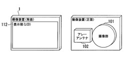
図2は、本発明の撮像装置を表す外観図である。図示する例では、撮像装置1は、撮像部101、アレーアンテナ102、及び表示部112を具備する。撮像部101、及びアレーアンテナ102は、撮像装置1の正面に互いに近接して配置されている。表示部112は、撮像装置1の背面に配置されている。
FIG. 2 is an external view showing the imaging apparatus of the present invention. In the illustrated example, the imaging apparatus 1 includes an imaging unit 101, an array antenna 102, and a display unit 112. The imaging unit 101 and the array antenna 102 are arranged close to each other on the front surface of the imaging device 1. The display unit 112 is disposed on the back surface of the imaging device 1.
撮像部101は、光を集光するレンズ(図示しない)と、レンズによって結像された被写体像を電気信号に変換するCCDやCMOSセンサー等(図示しない)の撮像素子とを有する。アレーアンテナ102は、2次元方向に並んだ複数のアンテナ素子(図示しない)から構成される。表示部112は、LCDや有機ELなどからなる表示デバイスである。
The imaging unit 101 includes a lens (not shown) that collects light and an imaging element such as a CCD or CMOS sensor (not shown) that converts an object image formed by the lens into an electrical signal. The array antenna 102 is composed of a plurality of antenna elements (not shown) arranged in a two-dimensional direction. The display unit 112 is a display device made up of an LCD, an organic EL, or the like.
図3は、撮像装置1の構成を表すブロック図である。図示する例では、撮像装置1は、撮像部101、アレーアンテナ102、無線部103、信号強度検出部104、識別情報抽出部105、アンテナ制御部106、記録制御部107、記録部108、相対角度抽出部109、推定位置計算部110、表示制御部111、表示部112、指示入力検知部113、及び無線接続切り替え制御部114を備える。
FIG. 3 is a block diagram showing the configuration of the imaging apparatus 1. In the illustrated example, the imaging apparatus 1 includes an imaging unit 101, an array antenna 102, a radio unit 103, a signal intensity detection unit 104, an identification information extraction unit 105, an antenna control unit 106, a recording control unit 107, a recording unit 108, and a relative angle. An extraction unit 109, an estimated position calculation unit 110, a display control unit 111, a display unit 112, an instruction input detection unit 113, and a wireless connection switching control unit 114 are provided.
撮像部101は、撮像素子が撮像した映像を示す映像情報を表示制御部111へ出力する。アレーアンテナ102(アンテナ)は、複数のアンテナ素子(図示しない)に出力する信号の位相を制御することにより、アンテナから出射される電波の出射角度(最大利得方向)に指向性を持つ電波を送受信することができる。また、アレーアンテナ102は、複数のアンテナ素子に出力する信号の位相を変化させることにより、電波の出射角度を変化させることができる。本明細書では、アレーアンテナ102の出射角度を次の様に定義する。すなわち、水平方向、垂直方向の各々について、アレーアンテナ102の出射面に垂直な方向を0°、アレーアンテナ102に平行な方向をそれぞれ+90°(例えば、左側)、-90°(例えば、右側)と定義する。アレーアンテナ102には、無線部103から、RF(Radio Frequency)信号が入力される。アンテナ制御部106は、アンテナの出射方向を指定する出射方向指定情報を無線部103に出力する。無線部103では出射方向指定情報を、複数のアンテナ素子(図示しない)に出力する信号の位相のズレ量に変換し、アレーアンテナ102へ出力し、アレーアンテナ102は、出射方向に向けて電波を送信する。また、アレーアンテナ102は、無線部103に、受信したRF信号を出力する。
The imaging unit 101 outputs video information indicating video captured by the imaging device to the display control unit 111. Array antenna 102 (antenna) transmits and receives radio waves having directivity at the emission angle (maximum gain direction) of radio waves emitted from the antenna by controlling the phase of signals output to a plurality of antenna elements (not shown). can do. Further, the array antenna 102 can change the emission angle of radio waves by changing the phase of signals output to a plurality of antenna elements. In this specification, the emission angle of the array antenna 102 is defined as follows. That is, for each of the horizontal direction and the vertical direction, the direction perpendicular to the output surface of the array antenna 102 is 0 °, and the directions parallel to the array antenna 102 are + 90 ° (eg, left side) and −90 ° (eg, right side), respectively. It is defined as An RF (Radio Frequency) signal is input from the radio unit 103 to the array antenna 102. The antenna control unit 106 outputs emission direction designation information for designating the emission direction of the antenna to the radio unit 103. The radio unit 103 converts the emission direction designation information into a phase shift amount of signals output to a plurality of antenna elements (not shown), and outputs them to the array antenna 102. The array antenna 102 transmits radio waves in the emission direction. Send. The array antenna 102 outputs the received RF signal to the radio unit 103.
無線部103は、無線接続切り替え制御部114から入力された、無線端末間の接続を切り替えることを指示する接続制御パケットをRF信号に変換する。無線部103は、無線端末を探索する探索パケット(探索データ)を生成し、生成した探索パケットをRF信号に変換する。
図1に示す各無線端末2-1、2-2,2-3は、この探索パケットを受信した場合、データ通信が可能な事を示す応答パケット(応答データ)を生成し、変調して送信する。撮像装置1は、この変調された応答パケットをアレーアンテナ102で受信し、無線部103で応答パケットに復調する。 Thewireless unit 103 converts the connection control packet input from the wireless connection switching control unit 114 and instructing switching of the connection between the wireless terminals into an RF signal. The wireless unit 103 generates a search packet (search data) for searching for a wireless terminal, and converts the generated search packet into an RF signal.
When each of the wireless terminals 2-1, 2-2 and 2-3 shown in FIG. 1 receives this search packet, it generates a response packet (response data) indicating that data communication is possible, modulates and transmits it To do. Theimaging apparatus 1 receives the modulated response packet with the array antenna 102 and demodulates the response packet with the radio unit 103.
図1に示す各無線端末2-1、2-2,2-3は、この探索パケットを受信した場合、データ通信が可能な事を示す応答パケット(応答データ)を生成し、変調して送信する。撮像装置1は、この変調された応答パケットをアレーアンテナ102で受信し、無線部103で応答パケットに復調する。 The
When each of the wireless terminals 2-1, 2-2 and 2-3 shown in FIG. 1 receives this search packet, it generates a response packet (response data) indicating that data communication is possible, modulates and transmits it To do. The
信号強度検出部104には、無線部103から、復調前の、アレーアンテナ102の複数のアンテナ素子からの入力が合成されたRF信号が入力される。信号強度検出部104は、入力されたRF信号の信号強度を検出する。信号強度検出部104は、記録制御部107から信号強度を出力させることを示す信号強度出力情報が入力されたとき、信号強度を示す信号強度情報を記録制御部107に出力する。識別情報抽出部105には、無線部103から復調後の応答パケットが入力される。応答パケットには、応答パケットを送信した無線端末の識別情報が含まれる。識別情報抽出部105は、応答パケットに含まれる識別情報を抽出する。識別情報抽出部105は、記録制御部107から識別情報を出力させることを示す識別情報出力情報が入力されたとき、識別情報を記録制御部107に出力する。
The signal intensity detection unit 104 receives from the radio unit 103 an RF signal obtained by combining inputs from a plurality of antenna elements of the array antenna 102 before demodulation. The signal strength detection unit 104 detects the signal strength of the input RF signal. When the signal strength output information indicating that the signal strength is output is input from the recording control unit 107, the signal strength detection unit 104 outputs the signal strength information indicating the signal strength to the recording control unit 107. The identification information extraction unit 105 receives the demodulated response packet from the radio unit 103. The response packet includes identification information of the wireless terminal that has transmitted the response packet. The identification information extraction unit 105 extracts identification information included in the response packet. When the identification information output information indicating that the identification information is output from the recording control unit 107 is input, the identification information extraction unit 105 outputs the identification information to the recording control unit 107.
アンテナ制御部106は、アレーアンテナ102のアンテナ各素子に加える信号の位相を変化させることにより、アレーアンテナ102の指向性の制御(最大利得方向、つまり出射角度の制御)を行う。アンテナ制御部106は、無線部103にアレーアンテナ102の出射方向を指定する出射方向指定情報を出力する。アンテナ制御部106は、アレーアンテナ102の出射角度を2次元方向に変化させる制御を行う。アンテナ制御部106は、撮像部101が撮像する視野角の全域(探索領域)を網羅するようにアレーアンテナ102の出射角度を変化させる制御を行う。アンテナ制御部106は、探索領域内のすべての方向に出射角度を変化させ終わったときに、探索領域内のすべての方向に出射角度を変化させ終わったことを示す探索終了情報を記録制御部107に出力する。アンテナ制御部106は、記録制御部107から、アレーアンテナ102の出射角度を出力させることを示す出射角度出力情報が入力されたとき、出射方向を示す出射方向情報を記録制御部107に出力する。
The antenna control unit 106 controls the directivity of the array antenna 102 (control of the maximum gain direction, that is, the emission angle) by changing the phase of the signal applied to each antenna element of the array antenna 102. The antenna control unit 106 outputs emission direction designation information for designating the emission direction of the array antenna 102 to the radio unit 103. The antenna control unit 106 performs control to change the emission angle of the array antenna 102 in a two-dimensional direction. The antenna control unit 106 performs control to change the emission angle of the array antenna 102 so as to cover the entire viewing angle (search area) captured by the imaging unit 101. When the antenna control unit 106 finishes changing the emission angle in all directions in the search area, the antenna control unit 106 records search end information indicating that the emission angle has been changed in all directions in the search area. Output to. When the output angle output information indicating that the output angle of the array antenna 102 is output is input from the recording control unit 107, the antenna control unit 106 outputs the emission direction information indicating the emission direction to the recording control unit 107.
記録制御部107は、記録部108に記録する情報が入力されると、入力された情報を記録部108に記録する。記録制御部107は、信号強度検出部104に信号強度出力情報を出力する。この信号強度出力情報に応じて信号強度検出部104から信号強度情報が記録制御部107に入力される。記録制御部107は、識別情報抽出部105に識別情報出力情報を出力する。この識別情報出力情報に応じて識別情報抽出部105から識別情報が記録制御部107に入力される。記録制御部107は、アンテナ制御部106に出射角度出力情報を出力する。この出射角度情報に応じてアンテナ制御部106から出射方向情報が記録制御部107に入力される。記録制御部107は、信号強度情報、識別情報、及び出射方向情報を記録部108に書き込む。記録制御部107は、アンテナ制御部106から探索終了情報が入力されたときに、探索終了情報を、記録部108を介して相対角度抽出部109に出力する。
When the information to be recorded in the recording unit 108 is input, the recording control unit 107 records the input information in the recording unit 108. The recording control unit 107 outputs signal strength output information to the signal strength detection unit 104. Signal strength information is input from the signal strength detection unit 104 to the recording control unit 107 according to the signal strength output information. The recording control unit 107 outputs identification information output information to the identification information extraction unit 105. In accordance with the identification information output information, identification information is input from the identification information extraction unit 105 to the recording control unit 107. The recording control unit 107 outputs the emission angle output information to the antenna control unit 106. Output direction information is input from the antenna control unit 106 to the recording control unit 107 in accordance with the output angle information. The recording control unit 107 writes the signal intensity information, identification information, and emission direction information in the recording unit 108. When the search end information is input from the antenna control unit 106, the recording control unit 107 outputs the search end information to the relative angle extraction unit 109 via the recording unit 108.
記録部108は、揮発性メモリや不揮発性メモリ、もしくはハードディスクなどから構成される。これらは、機器形状や使用方法、環境などに合わせて選択することができる。記録部108は、信号強度情報、識別情報、及び出射角度情報を関連づけたデータセットから構成される測定テーブルを記憶する。記録部108に記録された信号強度情報、識別情報、及び出射角度情報は、相対角度抽出部109から読み出される。記録部108は、記録制御部107から入力された探索終了情報を相対角度抽出部109に出力する。記録部108で記録される測定テーブルの形式の詳細については図面を参照しながら後述する。
The recording unit 108 includes a volatile memory, a nonvolatile memory, a hard disk, or the like. These can be selected according to the shape of the device, the method of use, the environment, and the like. The recording unit 108 stores a measurement table including a data set in which signal intensity information, identification information, and emission angle information are associated. The signal intensity information, the identification information, and the emission angle information recorded in the recording unit 108 are read from the relative angle extraction unit 109. The recording unit 108 outputs the search end information input from the recording control unit 107 to the relative angle extraction unit 109. Details of the format of the measurement table recorded by the recording unit 108 will be described later with reference to the drawings.
相対角度抽出部109は、記録部108から探索終了情報が入力されたときに、相対角度を抽出する。相対角度抽出部109は、記録部108に記録された測定テーブルから、同一の識別情報を持つデータセットを選択する。相対角度抽出部109は、選択されたデータセットの中で、信号強度が最大となるデータセットの出射角度を抽出し、この出射角度を、その識別情報をもつ無線端末の相対角度として抽出する。相対角度抽出部109は、抽出した相対角度を示す相対角度情報及び識別情報を、推定位置計算部110に出力する。相対角度抽出部109で行われる相対角度の抽出については図面を参照しながら詳しく後述する。
The relative angle extraction unit 109 extracts the relative angle when the search end information is input from the recording unit 108. The relative angle extraction unit 109 selects a data set having the same identification information from the measurement table recorded in the recording unit 108. The relative angle extraction unit 109 extracts the emission angle of the data set having the maximum signal intensity from the selected data set, and extracts this emission angle as the relative angle of the wireless terminal having the identification information. The relative angle extraction unit 109 outputs relative angle information and identification information indicating the extracted relative angle to the estimated position calculation unit 110. The relative angle extraction performed by the relative angle extraction unit 109 will be described in detail later with reference to the drawings.
推定位置計算部110は、相対角度抽出部109から入力された相対角度、撮像部101の画角、表示部112の画素数等に基づいて、表示部112上に表示する無線端末の識別情報の表示位置(推定位置)を計算する。推定位置計算部110は、計算した無線端末の識別情報の表示位置を示す表示位置情報を識別情報と紐付けて表示制御部111に出力する。推定位置計算部110で行われる無線端末の識別情報の表示位置の計算については図面を参照しながら詳しく後述する。
Based on the relative angle input from the relative angle extraction unit 109, the angle of view of the imaging unit 101, the number of pixels of the display unit 112, and the like, the estimated position calculation unit 110 displays the identification information of the wireless terminal displayed on the display unit 112. The display position (estimated position) is calculated. The estimated position calculation unit 110 associates the display position information indicating the calculated display position of the identification information of the wireless terminal with the identification information and outputs the display position information to the display control unit 111. Calculation of the display position of the identification information of the wireless terminal performed by the estimated position calculation unit 110 will be described in detail later with reference to the drawings.
表示制御部111には、撮像部101で撮像された各無線端末の外観の映像情報が入力される。表示制御部111は、推定位置計算部110から入力された識別情報そのもの、もしくは識別情報を操作者に理解し易い様に図形化または抽象化した識別画像を生成する。表示制御部111は、生成した識別画像を、映像情報が示す映像の、推定位置計算部110から入力された表示位置情報が示す表示位置に重畳した表示情報を生成する。表示制御部111は、生成した表示情報を表示部112に出力する。表示部112は、表示制御部111から表示情報が入力されると、表示情報が示す映像を表示面上に表示する。
The display control unit 111 receives video information of the appearance of each wireless terminal imaged by the imaging unit 101. The display control unit 111 generates the identification information input from the estimated position calculation unit 110 or an identification image that is graphicized or abstracted so that the operator can easily understand the identification information. The display control unit 111 generates display information in which the generated identification image is superimposed on the display position indicated by the display position information input from the estimated position calculation unit 110 of the video indicated by the video information. The display control unit 111 outputs the generated display information to the display unit 112. When the display information is input from the display control unit 111, the display unit 112 displays the video indicated by the display information on the display surface.
指示入力検知部113は、表示部112に設けられたタッチパネルや、カーソルなどを選択するジョグダイヤルスイッチ等のスイッチで構成される。指示入力検知部113は、表示部112に表示された無線端末の映像又はその近傍(選択領域とよぶ)に表示される識別情報を操作者が選択したことを検知する。操作者は、新たに無線端末2-2から無線端末2-1への接続を確立したい場合は、例えば、まず無線端末2-2の選択領域を選択し、続いて無線端末2-1の選択領域を選択する。この操作により、指示入力検知部113は、操作者が無線端末2-2から無線端末2-1への接続を選択したことを検知する。この例の場合、指示入力検知部113は、無線端末2-2から無線端末2-1への接続を示す選択情報を無線接続切り替え制御部114に出力する。無線接続切り替え制御部114は、指示入力検知部113から入力された選択情報に基づいて、無線端末間の無線接続を切断させ、新たな無線接続を確立させることを示す接続制御パケット(制御データ)を生成し、生成された接続制御パケットを無線部103に出力する。
The instruction input detection unit 113 includes a touch panel provided on the display unit 112 and a switch such as a jog dial switch for selecting a cursor. The instruction input detection unit 113 detects that the operator has selected identification information displayed on the video of the wireless terminal displayed on the display unit 112 or in the vicinity thereof (referred to as a selection area). When the operator wants to newly establish a connection from the wireless terminal 2-2 to the wireless terminal 2-1, for example, the operator first selects the selection area of the wireless terminal 2-2, and then selects the wireless terminal 2-1. Select an area. By this operation, the instruction input detection unit 113 detects that the operator has selected the connection from the wireless terminal 2-2 to the wireless terminal 2-1. In this example, the instruction input detection unit 113 outputs selection information indicating a connection from the wireless terminal 2-2 to the wireless terminal 2-1, to the wireless connection switching control unit 114. Based on the selection information input from the instruction input detection unit 113, the wireless connection switching control unit 114 disconnects the wireless connection between the wireless terminals and establishes a new wireless connection (control data). And the generated connection control packet is output to the wireless unit 103.
図4は、無線端末2の構成を表すブロック図である。図示する例では、無線端末2は、対撮像装置アンテナ201、対無線端末アンテナ202、対撮像装置無線部203、対無線端末無線部204、及び制御部205を具備する。対撮像装置アンテナ201は、対撮像装置無線部203から入力されたRF信号を撮像装置1に向けた電波として送信する。対撮像装置アンテナ201は、撮像装置1から送信された電波を受信する。対撮像装置アンテナ201は、受信した電波に対応するRF信号を対撮像装置無線部203に出力する。対無線端末アンテナ202は、対無線端末無線部204から入力されたRF信号を他の無線端末2に向けた電波として送信する。対無線端末アンテナ202は、他の無線端末2から送信された電波を受信する。対無線端末アンテナ202は、受信した電波に対応するRF信号を対無線端末無線部204に出力する。
FIG. 4 is a block diagram showing the configuration of the wireless terminal 2. In the illustrated example, the wireless terminal 2 includes an anti-imaging device antenna 201, an anti-wireless terminal antenna 202, an anti-imaging device radio unit 203, an anti-radio terminal radio unit 204, and a control unit 205. The anti-imaging device antenna 201 transmits the RF signal input from the anti-imaging device radio unit 203 as a radio wave directed to the imaging device 1. The imaging device antenna 201 receives radio waves transmitted from the imaging device 1. The imaging device antenna 201 outputs an RF signal corresponding to the received radio wave to the imaging device radio unit 203. The radio terminal antenna 202 transmits an RF signal input from the radio terminal radio unit 204 as a radio wave directed to another radio terminal 2. The anti-wireless terminal antenna 202 receives radio waves transmitted from other wireless terminals 2. The radio terminal antenna 202 outputs an RF signal corresponding to the received radio wave to the radio terminal radio unit 204.
対撮像装置無線部203は、対撮像装置アンテナ201からRF信号が入力されると、入力されたRF信号をベースバンド信号に変換し、変換されたベースバンド信号を制御部205に出力する。対撮像装置無線部203は、制御部205から入力されたベースバンド信号をRF信号に変換し、変換されたRF信号を対撮像装置アンテナ201に出力する。対無線端末無線部204は、対無線端末アンテナ202からRF信号が入力されると、入力されたRF信号をベースバンド信号にし、変換されたベースバンド信号を制御部205に出力する。対無線端末無線部204は、制御部205から入力されたベースバンド信号をRF信号に変換し、変換されたRF信号を対無線端末アンテナ202に出力する。
When the RF signal is input from the anti-imaging device antenna 201, the anti-imaging device wireless unit 203 converts the input RF signal into a baseband signal, and outputs the converted baseband signal to the control unit 205. The imaging device radio unit 203 converts the baseband signal input from the control unit 205 into an RF signal, and outputs the converted RF signal to the imaging device antenna 201. When the RF signal is input from the radio terminal antenna 202, the radio terminal radio unit 204 converts the input RF signal into a baseband signal and outputs the converted baseband signal to the control unit 205. The radio terminal radio unit 204 converts the baseband signal input from the control unit 205 into an RF signal, and outputs the converted RF signal to the radio terminal antenna 202.
制御部205には、対撮像装置無線部203から探索パケットが入力された場合、無線端末2のID情報を付加した応答パケットを対無線端末無線部204に出力する。制御部205には、対無線端末無線部204から無線端末間の接続を切り替えることを指示する接続制御パケットが入力される。制御部205は、接続制御パケットが示す接続の指示に応じて、接続要求を行う接続要求パケットや、切断要求を行う切断要求パケットを対無線端末無線部204に出力する事により、接続制御パケットが示す他の無線端末との接続を確立する。制御部205は、接続の確立後、制御部205に接続される、TV、DVDプレイヤー等の映像機器等と対無線端末無線部204との間で、映像データの伝送を行う。
When a search packet is input to the control unit 205 from the image capturing apparatus wireless unit 203, the response packet to which the ID information of the wireless terminal 2 is added is output to the wireless terminal wireless unit 204. The control unit 205 receives a connection control packet instructing switching of the connection between the wireless terminals from the wireless terminal wireless unit 204. In response to the connection instruction indicated by the connection control packet, the control unit 205 outputs a connection request packet for making a connection request and a disconnection request packet for making a disconnection request to the wireless terminal wireless unit 204, so that the connection control packet is received. Establish a connection with the other wireless terminal shown. After the connection is established, the control unit 205 transmits video data between the video equipment such as a TV and a DVD player connected to the control unit 205 and the wireless terminal wireless unit 204.
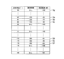
図5は、記録部108に記録される測定テーブルの一例を表す概略図である。図示する様に測定テーブルは、出射方向情報、識別情報、及び受信強度情報の各項目の列を有している。測定テーブルは、出射角度毎に識別情報、受信強度が格納される行と列からなる2次元の表形式のデータである。データセット5aは、出射角度は62°、識別情報はID3、受信強度は-25dBであることを示している。データセット5bは、出射角度は61°、識別情報はID3、受信強度は-15dBであることを示している。データセット5cは、出射角度は60°、識別情報はID3、受信強度は-40dBであることを示している。相対角度抽出部109は、同一の識別情報を持つデータセット5a~5cの受信強度を比較し、最大の受信強度を示すデータセット5bを選択する。相対角度抽出部109は、選択したデータセット5bの出射角度に基づいて、ID3を持った無線端末2-3の相対角度はアンテナの左側61°であると決定する。
FIG. 5 is a schematic diagram illustrating an example of a measurement table recorded in the recording unit 108. As shown in the figure, the measurement table has columns of items of emission direction information, identification information, and reception intensity information. The measurement table is two-dimensional tabular data composed of rows and columns in which identification information and reception intensity are stored for each emission angle. The data set 5a indicates that the emission angle is 62 °, the identification information is ID3, and the reception intensity is −25 dB. Data set 5b indicates that the emission angle is 61 °, the identification information is ID3, and the reception intensity is −15 dB. The data set 5c indicates that the emission angle is 60 °, the identification information is ID3, and the reception intensity is −40 dB. The relative angle extraction unit 109 compares the reception strengths of the data sets 5a to 5c having the same identification information, and selects the data set 5b indicating the maximum reception strength. Based on the emission angle of the selected data set 5b, the relative angle extraction unit 109 determines that the relative angle of the wireless terminal 2-3 having ID3 is 61 ° on the left side of the antenna.
また、データセット5dは、出射角度は-72°、識別情報はID2、受信強度は-51dBを示している。データセット5eは、出射角度は-73°、識別情報はID2、受信強度識別情報-40dBであることを示している。データセット5fは、出射角度は-74°、識別情報はID2、受信強度は-50dBであることを示している。相対角度抽出部109は、データセット5d~5fの受信強度を比較し、最大の受信強度を示すデータセット5eを選択する。相対角度抽出部109は、選択したデータセット5eの出射角度に基づいて、ID3を持った無線端末2-3の相対角度はアンテナの右側73°であると決定する。データセット5gは、出射角度は90°、識別情報はなし、受信強度は-100dBであることを示している。データセット5gは、アレーアンテナ102が出射角度90°方向から受信したRF信号の受信強度が、検出できる最低のRF信号の強度である受信限界強度(ここでは-100dB)より弱く、識別情報を特定できなかったことを示す。
Further, in the data set 5d, the emission angle is −72 °, the identification information is ID2, and the reception intensity is −51 dB. Data set 5e indicates that the emission angle is −73 °, the identification information is ID2, and the received intensity identification information is −40 dB. The data set 5f indicates that the emission angle is −74 °, the identification information is ID2, and the reception intensity is −50 dB. The relative angle extraction unit 109 compares the reception strengths of the data sets 5d to 5f, and selects the data set 5e indicating the maximum reception strength. Based on the emission angle of the selected data set 5e, the relative angle extraction unit 109 determines that the relative angle of the wireless terminal 2-3 having ID3 is 73 ° on the right side of the antenna. The data set 5g indicates that the emission angle is 90 °, there is no identification information, and the reception intensity is −100 dB. In the data set 5g, the reception strength of the RF signal received by the array antenna 102 from the direction of the emission angle of 90 ° is weaker than the reception limit strength (in this case, −100 dB) that is the lowest detectable RF signal strength, and the identification information is specified. Indicates that it was not possible.
図6は、撮像される無線端末2と、表示部112に表示される無線端末画像及び識別情報の表示位置の関係を示した概念図である。表示部112が表示面上に識別情報を表示する位置(推定位置)は、水平(X)方向と仰角(Y)方向の2次元空間の座標によって定められる。アレーアンテナ102と撮像部101の撮像中心を完全に合わせることは、実際には不可能である(図1参照)。しかし、アレーアンテナ102の中心と撮像部101の中心の間の距離が、撮像装置から無線端末までの距離に比べて十分小さく、アレーアンテナ102の中心と撮像部101の中心との不一致を無視できる場合がほとんどである。ここでは、アレーアンテナ102の中心と撮像部101の中心との不一致を無視できる場合について説明する。このとき、水平(X)方向と仰角(Y)方向の推定位置の計算は、各々独立しており、同様に考えることが可能であるので、以後、水平(X)方向のみについて説明を行い、仰角(Y)方向については説明を省略する。
FIG. 6 is a conceptual diagram showing the relationship between the wireless terminal 2 to be imaged, the wireless terminal image displayed on the display unit 112, and the display position of the identification information. The position (estimated position) at which the display unit 112 displays the identification information on the display surface is determined by the coordinates of the two-dimensional space in the horizontal (X) direction and the elevation angle (Y) direction. In practice, it is impossible to perfectly match the imaging centers of the array antenna 102 and the imaging unit 101 (see FIG. 1). However, the distance between the center of the array antenna 102 and the center of the imaging unit 101 is sufficiently smaller than the distance from the imaging device to the wireless terminal, and the mismatch between the center of the array antenna 102 and the center of the imaging unit 101 can be ignored. Most cases. Here, a case where the mismatch between the center of the array antenna 102 and the center of the imaging unit 101 can be ignored will be described. At this time, the calculation of the estimated position in the horizontal (X) direction and the elevation angle (Y) direction is independent of each other and can be considered in the same way, so only the horizontal (X) direction will be described below. Description of the elevation angle (Y) direction is omitted.
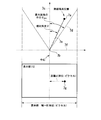
図7は、無線端末の実空間上の水平面内の位置と、表示部112上に示される無線端末の識別情報の表示位置を説明するための説明図である。点7aは、無線端末が実際に存在する位置を表す。アレーアンテナ102の中心と撮像部101の中心との不一致を無視できる前提から、図7では簡易的に、撮像部101の光軸(中心軸)と、アレーアンテナ102の中心と、表示部112の中心を同一軸上に表記している。点7bは、撮像部101及びアレーアンテナ102の中心を表す。破線7cは、撮像部101の光軸(中心軸)を表すとともに、それと重なる、アレーアンテナ102の出射面に垂直な方向(出射角度0°の方向)を表す。破線7dは、表示部112の最大画角を表す。破線7eは、撮像部101及びアレーアンテナ102の中心と無線端末を結ぶ線を表す。破線7fは、破線7cに垂直な面(撮像装置1の正面)を表す。点7gは、表示部112上に表示される無線端末及び識別情報の表示点を表す。この7gを示す表示部は理解を容易にする為に簡易的に表示部の正面図で表記している。
FIG. 7 is an explanatory diagram for explaining the position in the horizontal plane of the wireless terminal in the real space and the display position of the identification information of the wireless terminal displayed on the display unit 112. A point 7a represents a position where the wireless terminal actually exists. From the premise that the mismatch between the center of the array antenna 102 and the center of the imaging unit 101 can be ignored, in FIG. 7, the optical axis (center axis) of the imaging unit 101, the center of the array antenna 102, and the display unit 112 are simply illustrated. The center is shown on the same axis. A point 7 b represents the center of the imaging unit 101 and the array antenna 102. A broken line 7c represents the optical axis (center axis) of the imaging unit 101, and the direction perpendicular to the exit surface of the array antenna 102 (the direction at an exit angle of 0 °) overlapping therewith. A broken line 7 d represents the maximum angle of view of the display unit 112. A broken line 7e represents a line connecting the centers of the imaging unit 101 and the array antenna 102 and the wireless terminal. A broken line 7f represents a surface perpendicular to the broken line 7c (the front surface of the imaging device 1). A point 7g represents a display point of the wireless terminal and identification information displayed on the display unit 112. The display portion showing 7g is simply represented by a front view of the display portion for easy understanding.
表示部112の幅方向(水平方向)の解像度をW(単位はピクセル)とし、表示部112の中心から、表示部112上の、無線端末を表示すべき推定位置までの距離をd(単位はピクセル)とする。ここで、撮像部101で撮像された各無線端末の外観を含む映像は表示部の幅Wピクセルを全て使用して表示しているものとする。表示部の辺縁部等に撮像映像以外のもの(例えば、メニュー等)を表示する場合は、その部分のピクセル数を差し引いたものをWとすれば良い。
The resolution in the width direction (horizontal direction) of the display unit 112 is W (unit is pixel), and the distance from the center of the display unit 112 to the estimated position on the display unit 112 where the wireless terminal is to be displayed is d (unit: Pixel). Here, it is assumed that an image including the appearance of each wireless terminal imaged by the imaging unit 101 is displayed using all the width W pixels of the display unit. When something other than the captured image (for example, a menu or the like) is displayed on the edge or the like of the display portion, W can be obtained by subtracting the number of pixels in that portion.
表示部112の画角の中心と、撮像部101の視野角の中心は一致する(点7c)ものとし、さらに画角及び視野角はその中心から左右対称とする。最大画角の半分(破線7cと破線7dのなす角)をθmaxとし、アレーアンテナ102を用いて推定された無線端末の相対角度(破線7cと破線7eのなす角)をθとすると、距離dは式(1)で表される。
It is assumed that the center of the angle of view of the display unit 112 and the center of the viewing angle of the imaging unit 101 are coincident (point 7c), and the angle of view and the viewing angle are symmetrical from the center. If the maximum angle of view (the angle formed by the broken line 7c and the broken line 7d) is θmax, and the relative angle of the wireless terminal estimated using the array antenna 102 (the angle formed by the broken line 7c and the broken line 7e) is θ, the distance d Is represented by Formula (1).

ここでWは、表示部112のLCDパネルの水平方向のピクセル数であるので、LCDパネルが決まれば定数である。最大画角の半分の値であるθmaxも撮像系に固有な定数である。従って、相対角度θが決まれば距離d、つまり推定位置を決定できることになる。
Here, since W is the number of pixels in the horizontal direction of the LCD panel of the display unit 112, it is a constant if the LCD panel is determined. Θmax, which is half the maximum field angle, is also a constant unique to the imaging system. Therefore, if the relative angle θ is determined, the distance d, that is, the estimated position can be determined.
(無線端末の位置検出)
アンテナ制御部106は、出射方向指定情報をアレーアンテナ102へ出力する。アレーアンテナ102は、出射方向指定情報が示す出射方向へ向けて無線端末への探索パケットを送信する。無線端末が探索パケットを受信したときは、無線端末は撮像装置1に対して応答パケットを送信する。記録制御部107は、信号強度検出部104から信号強度情報を取得し、識別情報抽出部105から識別情報を取得し、アンテナ制御部106から出射方向指定情報を取得し、取得した各情報を記録部108に書き込む。 (Wireless terminal location detection)
Theantenna control unit 106 outputs the emission direction designation information to the array antenna 102. The array antenna 102 transmits a search packet to the wireless terminal in the emission direction indicated by the emission direction designation information. When the wireless terminal receives the search packet, the wireless terminal transmits a response packet to the imaging device 1. The recording control unit 107 acquires signal strength information from the signal strength detection unit 104, acquires identification information from the identification information extraction unit 105, acquires emission direction designation information from the antenna control unit 106, and records each acquired information Write to part 108.
アンテナ制御部106は、出射方向指定情報をアレーアンテナ102へ出力する。アレーアンテナ102は、出射方向指定情報が示す出射方向へ向けて無線端末への探索パケットを送信する。無線端末が探索パケットを受信したときは、無線端末は撮像装置1に対して応答パケットを送信する。記録制御部107は、信号強度検出部104から信号強度情報を取得し、識別情報抽出部105から識別情報を取得し、アンテナ制御部106から出射方向指定情報を取得し、取得した各情報を記録部108に書き込む。 (Wireless terminal location detection)
The
(推定位置の算出)
相対角度抽出部109は、記録部108に記録された測定テーブルに基づいて、相対角度を抽出する。相対角度抽出部109は、抽出された相対角度を示す相対角度情報及び識別情報を推定位置計算部110に出力する。推定位置計算部110は、相対角度抽出部109から入力された相対角度情報が示す相対角度、及びW、θmaxを式(1)に代入することにより、推定位置を示す距離dを算出する。 (Calculation of estimated position)
The relativeangle extraction unit 109 extracts a relative angle based on the measurement table recorded in the recording unit 108. The relative angle extraction unit 109 outputs relative angle information and identification information indicating the extracted relative angle to the estimated position calculation unit 110. The estimated position calculation unit 110 calculates the distance d indicating the estimated position by substituting the relative angle indicated by the relative angle information input from the relative angle extraction unit 109 and W and θmax into Expression (1).
相対角度抽出部109は、記録部108に記録された測定テーブルに基づいて、相対角度を抽出する。相対角度抽出部109は、抽出された相対角度を示す相対角度情報及び識別情報を推定位置計算部110に出力する。推定位置計算部110は、相対角度抽出部109から入力された相対角度情報が示す相対角度、及びW、θmaxを式(1)に代入することにより、推定位置を示す距離dを算出する。 (Calculation of estimated position)
The relative
(表示)
表示制御部111は、撮像部101で撮像された各無線端末2の外観を含む映像を表示部112に表示する。さらに、表示制御部111は、記録部108から入力された識別情報そのもの、もしくは識別情報を操作者に理解し易い様に図形化または抽象化したものを、付加情報として、推定位置計算部110で計算した推定位置に重畳して表示部112に表示する。推定位置は無線端末の位置を示しているので、映像上の無線端末2の近くにその付加情報が表示される。 (display)
Thedisplay control unit 111 displays an image including the appearance of each wireless terminal 2 imaged by the imaging unit 101 on the display unit 112. Further, the display control unit 111 uses the estimated position calculation unit 110 as identification information input from the recording unit 108 or a figure or abstraction of the identification information so as to be easily understood by the operator. It is superimposed on the calculated estimated position and displayed on the display unit 112. Since the estimated position indicates the position of the wireless terminal, the additional information is displayed near the wireless terminal 2 on the video.
表示制御部111は、撮像部101で撮像された各無線端末2の外観を含む映像を表示部112に表示する。さらに、表示制御部111は、記録部108から入力された識別情報そのもの、もしくは識別情報を操作者に理解し易い様に図形化または抽象化したものを、付加情報として、推定位置計算部110で計算した推定位置に重畳して表示部112に表示する。推定位置は無線端末の位置を示しているので、映像上の無線端末2の近くにその付加情報が表示される。 (display)
The
(無線端末の接続の切り替え)
無線端末2は、撮像装置1からの探索パケットに対する応答を行う第1のデータ通信機能と共に、撮像装置1とのデータ通信のデータ量よりも遥かに大きい映像等を含むデータを各無線端末2の間で通信する第2のデータ通信機能をもつ。また、第2のデータ通信を行う無線端末2の組み合わせと方向等は自由に変更できる事が望まれる。例えば、図2に示した無線端末2-1が液晶ディスプレーと接続され、無線端末2-2がDVDプレイヤーAと、無線端末2-3が別のDVDプレイヤーBと接続されていた場合を考える。撮像装置1は、それらの間の第2のデータ通信機能による無線接続の相手を切り替える場合、無線端末2間の接続を切り替えるための多機能リモコンに搭載された制御部という位置づけになる。 (Switching wireless terminal connection)
Thewireless terminal 2 receives data including video and the like that is much larger than the data amount of data communication with the imaging device 1 together with the first data communication function for responding to the search packet from the imaging device 1. A second data communication function for communicating between them. Further, it is desirable that the combination and direction of the wireless terminal 2 that performs the second data communication can be freely changed. For example, consider a case where the wireless terminal 2-1 shown in FIG. 2 is connected to a liquid crystal display, the wireless terminal 2-2 is connected to a DVD player A, and the wireless terminal 2-3 is connected to another DVD player B. The imaging device 1 is positioned as a control unit mounted on a multi-function remote controller for switching the connection between the wireless terminals 2 when switching the wireless connection partner using the second data communication function between them.
無線端末2は、撮像装置1からの探索パケットに対する応答を行う第1のデータ通信機能と共に、撮像装置1とのデータ通信のデータ量よりも遥かに大きい映像等を含むデータを各無線端末2の間で通信する第2のデータ通信機能をもつ。また、第2のデータ通信を行う無線端末2の組み合わせと方向等は自由に変更できる事が望まれる。例えば、図2に示した無線端末2-1が液晶ディスプレーと接続され、無線端末2-2がDVDプレイヤーAと、無線端末2-3が別のDVDプレイヤーBと接続されていた場合を考える。撮像装置1は、それらの間の第2のデータ通信機能による無線接続の相手を切り替える場合、無線端末2間の接続を切り替えるための多機能リモコンに搭載された制御部という位置づけになる。 (Switching wireless terminal connection)
The
ここでは、例として、ID1をもつ無線端末2-1とID3をもつ無線端末2-3間で動画を転送しているときに、ID1をもつ無線端末2-1とID2をもつ無線端末2-2間で動画を転送する様に変更する場合の接続の切り替えについて説明する。
Here, as an example, when moving pictures are transferred between the wireless terminal 2-1 having ID1 and the wireless terminal 2-3 having ID3, the wireless terminal 2-1 having ID1 and the wireless terminal 2- having ID2 are transferred. A description will be given of the switching of connections when changing to transfer a moving image between the two.
表示部112は、撮像部101が撮像した各無線端末の映像を表示するとともに、映像上の無線端末の位置付近に付加情報を表示する。指示入力検知部113は、操作者が無線端末2-2の付加情報もしくはその近辺を選択する指示を検知し、選択された付加情報を示す情報(選択情報)を生成する。指示入力検知部113は、選択情報を無線接続切り替え制御部114に出力する。無線接続切り替え制御部114は、選択情報が入力されると、付加情報に対応する無線端末2-2が選択されたと判断する。無線接続切り替え制御部114は、無線端末2-1に、無線端末2-3との接続を切断し、無線端末2-2との接続を確立することを指示する接続制御パケットを無線部103とアレーアンテナ102を経由して無線端末2-1に送信する。
The display unit 112 displays the video of each wireless terminal captured by the imaging unit 101 and displays additional information near the position of the wireless terminal on the video. The instruction input detection unit 113 detects an instruction for the operator to select additional information of the wireless terminal 2-2 or the vicinity thereof, and generates information (selection information) indicating the selected additional information. The instruction input detection unit 113 outputs the selection information to the wireless connection switching control unit 114. When the selection information is input, the wireless connection switching control unit 114 determines that the wireless terminal 2-2 corresponding to the additional information has been selected. The wireless connection switching control unit 114 transmits a connection control packet for instructing the wireless terminal 2-1 to disconnect the wireless terminal 2-3 and establish a connection with the wireless terminal 2-2. The data is transmitted to the wireless terminal 2-1 via the array antenna 102.
無線端末2-1の対撮像装置アンテナ201は、接続制御パケットを受信する。無線端末2-1の制御部205には、対撮像装置無線部203を介して接続制御パケットが入力される。無線端末2-1の制御部205は、無線端末2-3に向けた切断要求パケットを、対無線端末無線部204を介して対無線端末アンテナ202に出力する。無線端末2-1の対無線端末アンテナ202は、無線端末2-3に向けて切断要求パケットを送信する。無線端末2-3の対無線端末アンテナ202は、無線端末2-1からの切断要求パケットを受信する。無線端末2-3の制御部205には、対無線端末無線部204を介して切断要求パケットが入力される。無線端末2-3の制御部205は、対無線端末無線部204への映像機器等から入力された動画データの出力を停止する。
The imaging device antenna 201 of the wireless terminal 2-1 receives the connection control packet. A connection control packet is input to the control unit 205 of the wireless terminal 2-1 via the imaging device wireless unit 203. The control unit 205 of the wireless terminal 2-1 outputs a disconnection request packet for the wireless terminal 2-3 to the wireless terminal antenna 202 via the wireless terminal wireless unit 204. The radio terminal antenna 202 of the radio terminal 2-1 transmits a disconnection request packet to the radio terminal 2-3. The radio terminal antenna 202 of the radio terminal 2-3 receives the disconnection request packet from the radio terminal 2-1. The disconnection request packet is input to the control unit 205 of the wireless terminal 2-3 via the wireless terminal wireless unit 204. The control unit 205 of the wireless terminal 2-3 stops outputting the moving image data input from the video device or the like to the wireless terminal wireless unit 204.
一方、無線端末2-1の制御部205は、無線端末2-2に向けた接続要求パケットを、対無線端末無線部204と対無線端末アンテナ202を経由して送信する。無線端末2-2の対無線端末アンテナ202は、接続要求パケットを受信する。無線端末2-2の制御部205には、対無線端末無線部204を介して接続要求パケットが入力される。無線端末2-2の制御部205は、映像機器等から入力された動画データを対無線端末無線部204へ出力し、対無線端末アンテナ202を経由して動画データの送信を開始する。
On the other hand, the control unit 205 of the wireless terminal 2-1 transmits a connection request packet directed to the wireless terminal 2-2 via the wireless terminal wireless unit 204 and the wireless terminal antenna 202. The radio terminal antenna 202 of the radio terminal 2-2 receives the connection request packet. The connection request packet is input to the control unit 205 of the wireless terminal 2-2 via the wireless terminal wireless unit 204. The control unit 205 of the wireless terminal 2-2 outputs the moving image data input from the video equipment or the like to the wireless terminal wireless unit 204, and starts transmitting the moving image data via the wireless terminal antenna 202.
この一連の動作により本無線システム100では、撮像装置1に、無線端末2間の無線接続の切り替えの指示が入力され、この指示に応じて、各無線端末2の第2のデータ通信の送受信の組み合わせ及び方向を切り替える。
Through this series of operations, in the wireless system 100, an instruction to switch the wireless connection between the wireless terminals 2 is input to the imaging apparatus 1, and in response to this instruction, transmission / reception of the second data communication of each wireless terminal 2 is performed. Switch combination and direction.
このように、本実施形態によれば、無線端末2は、アレーアンテナ102が送信した探索パケットに呼応して、応答パケットを撮像装置1に送信する。アレーアンテナ102は、撮像部101の視野角の全域を網羅するように探索パケットの出射角度を変化させる。信号強度検知部104は、応答パケットの受信強度を測定する。相対角度計算部109は、受信強度に基づいて、無線端末2の相対角度を計算する。推定位置計算部110は、無線端末2の相対角度に基づいて推定位置を計算する。表示制御部111は、表示部112に、撮像部101が撮像した画像と共に推定位置に識別情報を表示させる。指示入力検知部113は、操作者からの無線切り替え指示を検知する。無線接続切り替え制御部114は、無線切り替え指示にしたがって接続制御パケットを無線端末2に送信する。無線端末2は、接続制御パケットが示す情報にしたがって各無線端末間の接続を切り替える。
Thus, according to the present embodiment, the wireless terminal 2 transmits a response packet to the imaging device 1 in response to the search packet transmitted by the array antenna 102. The array antenna 102 changes the outgoing angle of the search packet so as to cover the entire viewing angle of the imaging unit 101. The signal strength detection unit 104 measures the reception strength of the response packet. The relative angle calculation unit 109 calculates the relative angle of the wireless terminal 2 based on the reception intensity. The estimated position calculation unit 110 calculates an estimated position based on the relative angle of the wireless terminal 2. The display control unit 111 causes the display unit 112 to display identification information at the estimated position together with the image captured by the imaging unit 101. The instruction input detection unit 113 detects a wireless switching instruction from the operator. The wireless connection switching control unit 114 transmits a connection control packet to the wireless terminal 2 in accordance with the wireless switching instruction. The wireless terminal 2 switches the connection between the wireless terminals according to the information indicated by the connection control packet.
従って、本実施形態では、表示部上で識別情報やアイコン等の付加情報が実際の無線端末の近くに表示されるので、操作者が無線端末の属性や詳細を把握し易くなり、この識別情報やアイコン等をタッチパネルなどで選択することで、簡便な無線接続の切り替えの指示入力が可能となる。
Therefore, in the present embodiment, additional information such as identification information and icons is displayed near the actual wireless terminal on the display unit, so that the operator can easily grasp the attributes and details of the wireless terminal. By selecting an icon or an icon on the touch panel or the like, it is possible to input a simple instruction for switching the wireless connection.
なお、上記の構成では、アンテナ制御部106、記録制御部107、表示制御部111は、別々のブロックとして構成しているが、例えば単一の制御部に統合した構成としても良い。
In the above configuration, the antenna control unit 106, the recording control unit 107, and the display control unit 111 are configured as separate blocks, but may be configured to be integrated into a single control unit, for example.
なお、上記の説明では、撮像系の視野角が一定である場合について説明を行ってきたが、撮像系の視野角がズームの様に変更される場合も、ズームの設定値から、視野角を換算し、式(1)を用いて推定位置を決定できる。例えば、予めズームの倍率と視野角の関係を記録部108に記録しておき、この関係を参照することで、ズームの設定倍率に応じて、視野角を得ればよい。この場合当然のことながら、アレーアンテナの出射角度を変化させる範囲が、ズーム変更後の視野角をカバーしていなければならない。
In the above description, the case where the viewing angle of the imaging system is constant has been described. However, even when the viewing angle of the imaging system is changed like zooming, the viewing angle is set from the zoom setting value. After conversion, the estimated position can be determined using equation (1). For example, the relationship between the zoom magnification and the viewing angle may be recorded in the recording unit 108 in advance, and the viewing angle may be obtained according to the zoom setting magnification by referring to this relationship. In this case, as a matter of course, the range in which the output angle of the array antenna is changed must cover the viewing angle after the zoom change.
なお、アレーアンテナ102がその出射方向を変更しながら、無線端末2を探索する角度の範囲は、撮像部101の視野角と等しいか、それよりも大きい必要がある。もし、アレーアンテナ102が無線端末2を探索するする角度の範囲が撮像部101の視野角よりも小さい場合は、付加情報を表示できない領域であるデッドエリアが生じることになる。
Note that the range of angles at which the array antenna 102 searches the wireless terminal 2 while changing its emission direction needs to be equal to or larger than the viewing angle of the imaging unit 101. If the range of angles at which the array antenna 102 searches for the wireless terminal 2 is smaller than the viewing angle of the imaging unit 101, a dead area that is an area in which additional information cannot be displayed occurs.
なお、式(1)は、アレーアンテナ102のスキャン中心方向と撮像部101の撮像中心方向が同一という前提で成り立っているが、配置の都合等で方向に差異がある場合は、その差異分補正すれば良い。
Equation (1) is based on the premise that the scan center direction of the array antenna 102 and the image pickup center direction of the image pickup unit 101 are the same. If there is a difference in direction due to the location of the arrangement, the difference is corrected. Just do it.
なお、本実施形態において、表示部112は撮像部101の裏面に配置される例を示したが、これに限定されることは無く、操作をする上で、操作者の手や身体自体が撮像部101及びアレーアンテナ102の視野を遮らない様に配置すれば何処でも良い。また、ヒンジ等で可動としても良い。
In the present embodiment, the example in which the display unit 112 is arranged on the back surface of the imaging unit 101 is shown. However, the present invention is not limited to this, and the operator's hand or body itself is imaged when operating. Any arrangement may be used as long as it does not block the field of view of the part 101 and the array antenna 102. Further, it may be movable by a hinge or the like.
なお、測定テーブルに記憶される出射方向情報は、必ずしも最大利得方向に対応するものでなくてもよく、最大利得方向に近い値であればよい。
Note that the emission direction information stored in the measurement table does not necessarily correspond to the maximum gain direction, and may be a value close to the maximum gain direction.
なお、測定テーブルの更新の頻度は、撮像装置の視野を変更する速度や、画角内で無線端末が移動する速度に対して更新が追従できる頻度であることが望ましい。
It should be noted that the frequency of updating the measurement table is desirably a frequency at which the update can follow the speed at which the field of view of the imaging apparatus is changed and the speed at which the wireless terminal moves within the angle of view.
なお、撮像部101で撮像された各無線端末の外観を含む映像を表示する際、通常の動画カメラの様に25フレーム/秒から60フレーム/秒ないしはそれ以上の動画像を表示していても良いし、スチルカメラの様にレリーズを押した時の画像を表示しても良い。当然のことながら、動画像を表示する方が消費電力はより大きくなり、それに伴い撮像端末のバッテリーが大型化するので好ましくない。従って、実際は表示変更頻度と消費電力とのトレードオフを判断して決定すれば良い。また、ミリ波等を使用した高速なデータ転送無線システムを利用することで高速なスキャンが可能となり、撮像装置を操作者の手で自由に動かしても、付加情報の表示を追従させることが可能となる。
It should be noted that when displaying an image including the appearance of each wireless terminal imaged by the imaging unit 101, a moving image of 25 frames / second to 60 frames / second or more may be displayed like a normal video camera. It is also possible to display an image when the release is pressed like a still camera. As a matter of course, it is not preferable to display a moving image because the power consumption becomes larger and the battery of the imaging terminal becomes larger accordingly. Therefore, in practice, it may be determined by judging the trade-off between the display change frequency and the power consumption. In addition, a high-speed data transfer wireless system using millimeter waves, etc. enables high-speed scanning, and even if the imaging device is moved freely by the operator's hand, the display of additional information can be followed. It becomes.
(第2の実施形態)
以下、図面を参照しながら本発明の第2の実施形態について詳しく説明する。上記第1の実施形態では、無線端末2が、撮像装置1との通信を行う対撮像装置アンテナ201及び無線端末2間の通信を行う対無線端末アンテナ202を有する場合について説明した。本実施形態では、無線端末2が、共通の1つのアンテナで撮像装置1との通信及び無線端末2間の通信を行う場合について説明する。本実施形態に係る撮像装置1は、第1の実施形態における撮像装置1と同様であるため、説明を省略する。 (Second Embodiment)
Hereinafter, a second embodiment of the present invention will be described in detail with reference to the drawings. In the first embodiment, the case where thewireless terminal 2 includes the anti-imaging device antenna 201 that performs communication with the imaging device 1 and the anti-wireless terminal antenna 202 that performs communication between the wireless terminals 2 has been described. In the present embodiment, a case where the wireless terminal 2 performs communication with the imaging apparatus 1 and communication between the wireless terminals 2 using a common antenna will be described. Since the imaging device 1 according to the present embodiment is the same as the imaging device 1 according to the first embodiment, the description thereof is omitted.
以下、図面を参照しながら本発明の第2の実施形態について詳しく説明する。上記第1の実施形態では、無線端末2が、撮像装置1との通信を行う対撮像装置アンテナ201及び無線端末2間の通信を行う対無線端末アンテナ202を有する場合について説明した。本実施形態では、無線端末2が、共通の1つのアンテナで撮像装置1との通信及び無線端末2間の通信を行う場合について説明する。本実施形態に係る撮像装置1は、第1の実施形態における撮像装置1と同様であるため、説明を省略する。 (Second Embodiment)
Hereinafter, a second embodiment of the present invention will be described in detail with reference to the drawings. In the first embodiment, the case where the
図8は、本実施形態に係る無線端末2aの構成を表すブロック図である。図示する例では、無線端末2aは、アンテナ201a、無線部203a、及び制御部205aを具備する。アンテナ201aは、撮像装置1との通信及びそれより大きなデータ転送が行われる他の無線端末2aとの通信の双方に用いられる。アンテナ201aは、無線部203aから入力されたRF信号を撮像装置1及び他の無線端末2aに向けた電波として送信する。アンテナ201aは、撮像装置1及び他の無線端末2aから送信された電波を受信する。アンテナ201aは、受信した電波に対応するRF信号を無線部203aに出力する。
FIG. 8 is a block diagram showing the configuration of the wireless terminal 2a according to the present embodiment. In the illustrated example, the wireless terminal 2a includes an antenna 201a, a wireless unit 203a, and a control unit 205a. The antenna 201a is used for both communication with the imaging device 1 and communication with another wireless terminal 2a that performs larger data transfer. The antenna 201a transmits the RF signal input from the wireless unit 203a as a radio wave directed to the imaging device 1 and the other wireless terminal 2a. The antenna 201a receives radio waves transmitted from the imaging device 1 and the other wireless terminal 2a. The antenna 201a outputs an RF signal corresponding to the received radio wave to the wireless unit 203a.
無線部203aは、アンテナ201aからRF信号が入力されると、入力されたRF信号をベースバンド信号に変換し、変換されたベースバンド信号を制御部205aに出力する。無線部203aは、制御部205aから入力されたベースバンド信号をRF信号に変換し、変換されたRF信号をアンテナ201aに出力する。制御部205aは、無線部203aから探索パケットが入力された場合、無線端末2aのID情報を付加した応答パケットを無線部203aに出力する。制御部205aには、無線部203aから無線端末間の接続を切り替えることを指示する接続制御パケットが入力される。制御部205aは、接続制御パケットが示す接続の指示に応じて、接続要求を行う接続要求パケットや、切断要求を行う切断要求パケットを無線部203aに出力する事により、接続制御パケットが示す他の無線端末との接続を確立する。制御部205aは、接続の確立後、制御部205aに接続される、TV、DVDプレイヤー等の映像機器等と無線部203aとの間で、映像データの伝送を行う。
When the RF signal is input from the antenna 201a, the wireless unit 203a converts the input RF signal into a baseband signal and outputs the converted baseband signal to the control unit 205a. The radio unit 203a converts the baseband signal input from the control unit 205a into an RF signal, and outputs the converted RF signal to the antenna 201a. When the search packet is input from the wireless unit 203a, the control unit 205a outputs a response packet to which the ID information of the wireless terminal 2a is added to the wireless unit 203a. The control unit 205a receives a connection control packet instructing switching of the connection between the wireless terminals from the wireless unit 203a. In response to a connection instruction indicated by the connection control packet, the control unit 205a outputs a connection request packet for making a connection request or a disconnection request packet for making a disconnection request to the wireless unit 203a, so that Establish a connection with the wireless terminal. After establishing the connection, the control unit 205a transmits video data between the wireless unit 203a and a video device such as a TV or a DVD player connected to the control unit 205a.
ここでは、例として、ID1をもつ無線端末2a-1とID3をもつ無線端末2a-3間で動画を転送していたものを、ID1を持つ無線端末2a-1とID2をもつ無線端末2a-2間で動画を転送する様に変更する場合の接続の切り替えについて説明する。
Here, as an example, a moving picture transferred between the wireless terminal 2a-1 having ID1 and the wireless terminal 2a-3 having ID3 is referred to as the wireless terminal 2a-1 having ID1 and the wireless terminal 2a- having ID2. A description will be given of the switching of connections when changing to transfer a moving image between the two.
表示部112は、撮像部101が撮像した各無線端末の映像を表示するとともに、映像上の無線端末の位置付近に付加情報を表示する。指示入力検知部113は、操作者が無線端末2a-2の付加情報もしくはその近辺を選択する指示を検知し、選択された付加情報を示す情報(選択情報)を生成し、無線接続切り替え制御部114に出力する。無線接続切り替え制御部114は、選択情報が入力されると、付加情報に対応する無線端末2a-2が選択されたと判断する。無線接続切り替え制御部114は、無線端末2a-1に、無線端末2a-3との接続を切断し、無線端末2a-2との接続を確立することを示す接続制御パケットを無線部103とアレーアンテナ102を経由して無線端末2a-1に送信する。
The display unit 112 displays the video of each wireless terminal captured by the imaging unit 101 and displays additional information near the position of the wireless terminal on the video. The instruction input detection unit 113 detects an instruction for the operator to select additional information of the wireless terminal 2a-2 or the vicinity thereof, generates information (selection information) indicating the selected additional information, and a wireless connection switching control unit To 114. When the selection information is input, the wireless connection switching control unit 114 determines that the wireless terminal 2a-2 corresponding to the additional information has been selected. The wireless connection switching control unit 114 sends a connection control packet indicating that the wireless terminal 2a-1 is disconnected from the wireless terminal 2a-3 and connected to the wireless terminal 2a-2 to the wireless unit 103. The data is transmitted to the wireless terminal 2a-1 via the antenna 102.
無線端末2a-1のアンテナ201aは、接続制御パケットを受信する。無線端末2a-1の制御部205aには、無線部203aを介して接続制御パケットが入力される。無線端末2a-1の制御部205aは、無線端末2a-3に向けた切断要求パケットを、無線部203aを介してアンテナ201aに出力する。無線端末2a-1のアンテナ201aは、無線端末2a-3に向けて切断要求パケットを送信する。無線端末2a-3のアンテナ201aは、切断要求パケットを受信する。無線端末2a-3の制御部205aには、無線部203aを介して切断要求パケットが入力される。無線端末2a-3の制御部205aは、映像機器等から入力された動画データの無線部203aへの出力を停止する。
The antenna 201a of the wireless terminal 2a-1 receives the connection control packet. The connection control packet is input to the control unit 205a of the wireless terminal 2a-1 via the wireless unit 203a. The control unit 205a of the wireless terminal 2a-1 outputs a disconnection request packet directed to the wireless terminal 2a-3 to the antenna 201a via the wireless unit 203a. The antenna 201a of the wireless terminal 2a-1 transmits a disconnection request packet to the wireless terminal 2a-3. The antenna 201a of the wireless terminal 2a-3 receives the disconnection request packet. A disconnection request packet is input to the control unit 205a of the wireless terminal 2a-3 via the wireless unit 203a. The control unit 205a of the wireless terminal 2a-3 stops outputting the moving image data input from the video equipment or the like to the wireless unit 203a.
一方、無線端末2a-1の制御部205aは、無線端末2a-2に向けた接続要求パケットを、無線部203aとアンテナ201aを経由して送信する。無線端末2a-2のアンテナ201aは、接続要求パケットを受信する。無線端末2a-2の制御部205aには、無線部203aを介して接続要求パケットが入力される。無線端末2a-2の制御部205aは、映像機器等から入力された動画データを無線部203aへ出力し、アンテナ201aを経由して、動画データの送信を開始する。
On the other hand, the control unit 205a of the wireless terminal 2a-1 transmits a connection request packet directed to the wireless terminal 2a-2 via the wireless unit 203a and the antenna 201a. The antenna 201a of the wireless terminal 2a-2 receives the connection request packet. The connection request packet is input to the control unit 205a of the wireless terminal 2a-2 via the wireless unit 203a. The control unit 205a of the wireless terminal 2a-2 outputs the moving image data input from the video equipment or the like to the wireless unit 203a, and starts transmitting the moving image data via the antenna 201a.
このように、本実施形態によれば、無線端末2aは、同一のアンテナ201aで撮像装置1及び他の無線端末2aとの通信を行う。これにより、外部制御装置(撮像装置)からの無線通信による無線端末間の通信の切り替えを行う場合に、無線端末側に通信切り替え専用の無線部を具備する必要がなくなり、コスト低減と小型化が可能となる。
Thus, according to the present embodiment, the wireless terminal 2a communicates with the imaging device 1 and the other wireless terminal 2a using the same antenna 201a. As a result, when switching communication between wireless terminals by wireless communication from an external control device (imaging device), there is no need to provide a wireless unit dedicated to communication switching on the wireless terminal side, which reduces cost and size. It becomes possible.
なお、上述の各実施形態において、アレーアンテナ102の代わりに、機械的に水平方向及び仰方向に指向性を変化させることが可能な機構を有するアンテナを用いてもよい。
In each of the above-described embodiments, an antenna having a mechanism capable of mechanically changing the directivity in the horizontal direction and the elevating direction may be used instead of the array antenna 102.
なお、アレーアンテナを使用する場合において、無線部で使用する無線周波数が高いほどアンテナの小型化が容易となる。例えば、60GHz帯などのミリ波を用いた場合、アンテナをICチップの上に配置し、小型化を実現できる。
When using an array antenna, the higher the radio frequency used in the radio unit, the easier it is to reduce the size of the antenna. For example, when a millimeter wave of 60 GHz band or the like is used, the antenna can be arranged on the IC chip to achieve downsizing.
以上、図面を参照してこの発明の各実施形態について詳しく説明してきたが、具体的な構成は上述のものに限られることはなく、この発明の要旨を逸脱しない範囲内において様々な設計変更等をすることが可能である。
As described above, the embodiments of the present invention have been described in detail with reference to the drawings. However, the specific configuration is not limited to that described above, and various design changes and the like can be made without departing from the scope of the present invention. It is possible to
本発明は、撮像装置および無線システムに広く適用でき、操作者が容易に無線端末の切り替えを行うことができるようになる。
The present invention can be widely applied to imaging apparatuses and wireless systems, and allows an operator to easily switch wireless terminals.
1、9a・・・撮像装置
2、2-1、2-2、2-3、2a、9c-1、9c-2、9c-3・・・無線端末
100・・・無線システム
101・・・撮像部
102・・・アレーアンテナ
103、9b・・・表示部
104・・・無線部
105・・・信号強度検出部
106・・・識別情報抽出部
107・・・アンテナ制御部
108・・・記録制御部
109・・・記録部
110・・・相対角度抽出部
111・・・推定位置計算部
112・・・表示制御部
113・・・指示入力検知部
114・・・無線接続切り替え制御部
201・・・対撮像装置アンテナ
201a・・・アンテナ
202・・・対無線端末アンテナ
203・・・対撮像装置無線部
203a・・・無線部
204・・・対無線端末無線部
205、205a・・・制御部
DESCRIPTION OF SYMBOLS 1, 9a ... Imaging device 2, 2-1, 2-2, 2-3, 2a, 9c-1, 9c-2, 9c-3 ... Wireless terminal 100 ... Wireless system 101 ... Imaging unit 102 ... array antenna 103, 9b ... display unit 104 ... radio unit 105 ... signal intensity detection unit 106 ... identification information extraction unit 107 ... antenna control unit 108 ... recording Control unit 109 ... Recording unit 110 ... Relative angle extraction unit 111 ... Estimated position calculation unit 112 ... Display control unit 113 ... Instruction input detection unit 114 ... Wireless connection switching control unit 201 .. Anti-imaging device antenna 201a ... Antenna 202 ... Anti-radio terminal antenna 203 ... Anti-imaging device radio unit 203a ... Radio unit 204 ... Anti-wireless terminal radio unit 205, 205a ... Control Part
2、2-1、2-2、2-3、2a、9c-1、9c-2、9c-3・・・無線端末
100・・・無線システム
101・・・撮像部
102・・・アレーアンテナ
103、9b・・・表示部
104・・・無線部
105・・・信号強度検出部
106・・・識別情報抽出部
107・・・アンテナ制御部
108・・・記録制御部
109・・・記録部
110・・・相対角度抽出部
111・・・推定位置計算部
112・・・表示制御部
113・・・指示入力検知部
114・・・無線接続切り替え制御部
201・・・対撮像装置アンテナ
201a・・・アンテナ
202・・・対無線端末アンテナ
203・・・対撮像装置無線部
203a・・・無線部
204・・・対無線端末無線部
205、205a・・・制御部
DESCRIPTION OF
Claims (4)
- 画像を撮像する撮像部と、
前記画像を表示する表示部と、
前記撮像部に対して予め決められた位置に配置されるアンテナと、
前記アンテナの最大利得方向を変化させて前記アンテナの指向性を制御するアンテナ制御部と、
前記アンテナを経由して、1つ以上の無線端末に対して探索データを送信し、かつ、前記探索データに対する応答データを受信し、さらに制御データを送信する無線部と、
前記応答データの受信強度を検出する受信強度検出部と、
前記応答データの送信元である前記無線端末の識別情報を抽出する識別情報抽出部と、
前記識別情報と前記受信強度と前記最大利得方向とを関連づけるデータセットを生成する制御を行う記録制御部と、
前記データセットを記録する記録部と、
前記記録部に記録された同一の前記識別情報を持つ前記データセットの中で前記受信強度が他の前記受信強度よりも相対的に大きい前記データセットの前記最大利得方向を、撮像装置を基準とする前記無線端末の相対的な方向を示す相対角度として抽出する相対角度抽出部と、
前記表示部の画角と前記相対角度に基づいて、前記表示部に表示される前記画像上の前記無線端末の推定位置を計算する推定位置計算部と、
前記表示部に、前記画像を表示させるとともに、前記識別情報に対応する前記無線端末を特定する端末情報を前記推定位置に重畳表示する様に表示させる制御を行う表示制御部と、
前記表示部に表示された前記端末情報を操作者が選択する指示を検知する事で、複数の前記無線端末間での無線接続に関する操作者の指示を検知する指示入力検知部と、
前記指示入力検知部が検知した前記操作者の指示に基づき、少なくとも1つ以上の前記無線端末に対して無線接続に関する前記制御データを送信する制御を行う無線接続切り替え制御部と、
を有する撮像装置。 An imaging unit that captures an image;
A display unit for displaying the image;
An antenna disposed at a predetermined position with respect to the imaging unit;
An antenna control unit for controlling the directivity of the antenna by changing the maximum gain direction of the antenna;
A wireless unit that transmits search data to one or more wireless terminals via the antenna, receives response data for the search data, and further transmits control data;
A reception intensity detection unit for detecting the reception intensity of the response data;
An identification information extraction unit that extracts identification information of the wireless terminal that is the transmission source of the response data;
A recording control unit that performs control to generate a data set that associates the identification information, the reception intensity, and the maximum gain direction;
A recording unit for recording the data set;
In the data set having the same identification information recorded in the recording unit, the maximum gain direction of the data set in which the reception intensity is relatively larger than the other reception intensity is based on the imaging device. A relative angle extraction unit that extracts a relative angle indicating a relative direction of the wireless terminal;
An estimated position calculation unit that calculates an estimated position of the wireless terminal on the image displayed on the display unit based on the angle of view of the display unit and the relative angle;
A display control unit for controlling the display unit to display the image and to display the terminal information for specifying the wireless terminal corresponding to the identification information so as to be superimposed on the estimated position;
An instruction input detection unit for detecting an instruction of an operator regarding a wireless connection between the plurality of wireless terminals by detecting an instruction for an operator to select the terminal information displayed on the display unit;
A wireless connection switching control unit that performs control to transmit the control data related to wireless connection to at least one or more wireless terminals based on the instructions of the operator detected by the instruction input detection unit;
An imaging apparatus having - 前記アンテナは複数のアンテナ素子からなるアレーアンテナで、
前記アンテナ制御部は前記アンテナ素子に加える信号の位相を変化させることにより、指向性の制御を行う、請求項1に記載の撮像装置。 The antenna is an array antenna composed of a plurality of antenna elements,
The imaging apparatus according to claim 1, wherein the antenna control unit controls directivity by changing a phase of a signal applied to the antenna element. - 請求項1に記載の撮像装置と、
前記撮像装置から受信した前記制御データに基づいて、前記無線端末間の接続の切り替えを行う複数の前記無線端末と、
を有する無線システム。 An imaging device according to claim 1;
A plurality of the wireless terminals that switch connection between the wireless terminals based on the control data received from the imaging device;
A wireless system. - 前記無線端末は、他の前記無線端末との間の無線接続及び前記撮像装置との無線接続を、同一のアンテナ及び無線部を用いて行う、請求項3に記載の無線システム。 The wireless system according to claim 3, wherein the wireless terminal performs wireless connection with the other wireless terminal and wireless connection with the imaging apparatus using the same antenna and wireless unit.
Priority Applications (2)
| Application Number | Priority Date | Filing Date | Title |
|---|---|---|---|
| EP12803413.9A EP2725871A4 (en) | 2011-06-24 | 2012-06-08 | Imaging device and wireless system |
| US14/105,924 US9092049B2 (en) | 2011-06-24 | 2013-12-13 | Imaging apparatus and wireless system |
Applications Claiming Priority (2)
| Application Number | Priority Date | Filing Date | Title |
|---|---|---|---|
| JP2011-140830 | 2011-06-24 | ||
| JP2011140830A JP5802450B2 (en) | 2011-06-24 | 2011-06-24 | Imaging device, wireless system |
Related Child Applications (1)
| Application Number | Title | Priority Date | Filing Date |
|---|---|---|---|
| US14/105,924 Continuation US9092049B2 (en) | 2011-06-24 | 2013-12-13 | Imaging apparatus and wireless system |
Publications (1)
| Publication Number | Publication Date |
|---|---|
| WO2012176628A1 true WO2012176628A1 (en) | 2012-12-27 |
Family
ID=47422468
Family Applications (1)
| Application Number | Title | Priority Date | Filing Date |
|---|---|---|---|
| PCT/JP2012/064750 WO2012176628A1 (en) | 2011-06-24 | 2012-06-08 | Imaging device and wireless system |
Country Status (4)
| Country | Link |
|---|---|
| US (1) | US9092049B2 (en) |
| EP (1) | EP2725871A4 (en) |
| JP (1) | JP5802450B2 (en) |
| WO (1) | WO2012176628A1 (en) |
Families Citing this family (10)
| Publication number | Priority date | Publication date | Assignee | Title |
|---|---|---|---|---|
| JP5753009B2 (en) * | 2011-06-24 | 2015-07-22 | オリンパス株式会社 | Imaging device, wireless system |
| JP6387700B2 (en) * | 2014-06-18 | 2018-09-12 | ソニー株式会社 | Information processing apparatus, information processing system, information processing apparatus control method, and program |
| US10412549B2 (en) * | 2014-11-25 | 2019-09-10 | Huawei Technologies Co., Ltd. | Orientation method, device, and system |
| JP6435821B2 (en) * | 2014-12-04 | 2018-12-12 | セイコーエプソン株式会社 | Printing apparatus, printing system, and printing apparatus control method |
| JP6405957B2 (en) | 2014-12-04 | 2018-10-17 | セイコーエプソン株式会社 | Printing apparatus, printing system, and printing apparatus control method |
| US10356613B2 (en) * | 2015-02-27 | 2019-07-16 | Ricoh Company, Ltd. | Information processing device and information processing system that executes a process based on a user operation received from an operator |
| JP6571997B2 (en) * | 2015-06-08 | 2019-09-04 | キヤノン株式会社 | COMMUNICATION DEVICE, COMMUNICATION DEVICE CONTROL METHOD, AND PROGRAM |
| US9871574B2 (en) * | 2016-04-05 | 2018-01-16 | Getac Technology Corporation | Antenna signal transmission apparatus and antenna signal transmission method |
| JP6682365B2 (en) * | 2016-06-01 | 2020-04-15 | キヤノン株式会社 | COMMUNICATION DEVICE, COMMUNICATION DEVICE CONTROL METHOD, AND PROGRAM |
| CN111009106B (en) * | 2018-10-05 | 2021-11-30 | 财团法人工业技术研究院 | Human-computer interface system and communication control device thereof |
Citations (7)
| Publication number | Priority date | Publication date | Assignee | Title |
|---|---|---|---|---|
| JP2002218503A (en) * | 2001-01-22 | 2002-08-02 | Fuji Photo Film Co Ltd | Communication system and mobile terminal |
| JP3441422B2 (en) | 2000-05-31 | 2003-09-02 | 株式会社東芝 | Radio control terminal device and radio system |
| JP2004297422A (en) * | 2003-03-27 | 2004-10-21 | Hitachi Ltd | Mobile communication control method |
| JP2008160879A (en) * | 2008-02-04 | 2008-07-10 | Nikon Corp | Electronic camera, image display device and image display method |
| JP2008305043A (en) * | 2007-06-06 | 2008-12-18 | Hiroshi Nohara | Distance/location confirmation system |
| JP2009164803A (en) * | 2007-12-28 | 2009-07-23 | Yamatake Corp | Specific information setting system and specific information setting apparatus |
| JP2010114798A (en) * | 2008-11-10 | 2010-05-20 | Mitsubishi Electric Corp | Wireless transmission system |
Family Cites Families (22)
| Publication number | Priority date | Publication date | Assignee | Title |
|---|---|---|---|---|
| US6628899B1 (en) * | 1999-10-08 | 2003-09-30 | Fuji Photo Film Co., Ltd. | Image photographing system, image processing system, and image providing system connecting them, as well as photographing camera, image editing apparatus, image order sheet for each object and method of ordering images for each object |
| KR100744362B1 (en) * | 2001-09-26 | 2007-07-30 | 삼성전자주식회사 | Device and method for suppressing interference of reverse link in in-building mobile communication system |
| US20030134648A1 (en) * | 2001-10-04 | 2003-07-17 | Reed Mark Jefferson | Machine for providing a dynamic data base of geographic location information for a plurality of wireless devices and process for making same |
| AU2002354181A1 (en) * | 2001-12-03 | 2003-06-17 | Nikon Corporation | Electronic apparatus, electronic camera, electronic device, image display apparatus, and image transmission system |
| KR100557084B1 (en) * | 2003-08-21 | 2006-03-03 | 삼성전자주식회사 | Camera lens assembly for portable wireless terminal |
| US7477841B2 (en) * | 2003-09-22 | 2009-01-13 | Fujifilm Corporation | Service provision system and automatic photography system |
| US7373109B2 (en) | 2003-11-04 | 2008-05-13 | Nokia Corporation | System and method for registering attendance of entities associated with content creation |
| JP2005348028A (en) * | 2004-06-02 | 2005-12-15 | Fuji Photo Film Co Ltd | Imaging apparatus |
| JP4479386B2 (en) | 2004-07-08 | 2010-06-09 | パナソニック株式会社 | Imaging device |
| JP2006033630A (en) * | 2004-07-20 | 2006-02-02 | Funai Electric Co Ltd | Digital television broadcast signal receiver |
| JP2006174010A (en) | 2004-12-15 | 2006-06-29 | Fuji Photo Film Co Ltd | Imaging apparatus |
| US20080166966A1 (en) * | 2004-12-20 | 2008-07-10 | Shogo Hamasaki | Wireless Communication Apparatus and Communication Control Method |
| US7769348B2 (en) * | 2006-11-24 | 2010-08-03 | Sony Ericsson Mobile Communications Ab | Ad-hoc connectivity system and method |
| WO2008087974A1 (en) * | 2007-01-16 | 2008-07-24 | Panasonic Corporation | Data processing apparatus and method, and recording medium |
| JP2009094890A (en) * | 2007-10-10 | 2009-04-30 | Olympus Imaging Corp | Digital camera |
| KR101110969B1 (en) * | 2007-11-28 | 2012-02-20 | 노키아 코포레이션 | Wireless device detection |
| JP5658144B2 (en) * | 2008-05-28 | 2015-01-21 | グーグル・インコーポレーテッド | Visual navigation method, system, and computer-readable recording medium |
| KR101443339B1 (en) * | 2008-10-01 | 2014-09-22 | 엘지전자 주식회사 | Mobile terminal and Antena connection cable for mobile terminal |
| US9571713B2 (en) | 2008-12-05 | 2017-02-14 | International Business Machines Corporation | Photograph authorization system |
| JP5282710B2 (en) * | 2009-09-28 | 2013-09-04 | 富士通株式会社 | Communication device |
| KR101643869B1 (en) * | 2010-05-06 | 2016-07-29 | 엘지전자 주식회사 | Operating a Mobile Termianl with a Vibration Module |
| JP5753009B2 (en) * | 2011-06-24 | 2015-07-22 | オリンパス株式会社 | Imaging device, wireless system |
-
2011
- 2011-06-24 JP JP2011140830A patent/JP5802450B2/en active Active
-
2012
- 2012-06-08 WO PCT/JP2012/064750 patent/WO2012176628A1/en active Application Filing
- 2012-06-08 EP EP12803413.9A patent/EP2725871A4/en not_active Withdrawn
-
2013
- 2013-12-13 US US14/105,924 patent/US9092049B2/en active Active
Patent Citations (7)
| Publication number | Priority date | Publication date | Assignee | Title |
|---|---|---|---|---|
| JP3441422B2 (en) | 2000-05-31 | 2003-09-02 | 株式会社東芝 | Radio control terminal device and radio system |
| JP2002218503A (en) * | 2001-01-22 | 2002-08-02 | Fuji Photo Film Co Ltd | Communication system and mobile terminal |
| JP2004297422A (en) * | 2003-03-27 | 2004-10-21 | Hitachi Ltd | Mobile communication control method |
| JP2008305043A (en) * | 2007-06-06 | 2008-12-18 | Hiroshi Nohara | Distance/location confirmation system |
| JP2009164803A (en) * | 2007-12-28 | 2009-07-23 | Yamatake Corp | Specific information setting system and specific information setting apparatus |
| JP2008160879A (en) * | 2008-02-04 | 2008-07-10 | Nikon Corp | Electronic camera, image display device and image display method |
| JP2010114798A (en) * | 2008-11-10 | 2010-05-20 | Mitsubishi Electric Corp | Wireless transmission system |
Non-Patent Citations (1)
| Title |
|---|
| See also references of EP2725871A4 |
Also Published As
| Publication number | Publication date |
|---|---|
| JP2013009180A (en) | 2013-01-10 |
| JP5802450B2 (en) | 2015-10-28 |
| EP2725871A4 (en) | 2015-08-12 |
| EP2725871A1 (en) | 2014-04-30 |
| US20140104443A1 (en) | 2014-04-17 |
| US9092049B2 (en) | 2015-07-28 |
Similar Documents
| Publication | Publication Date | Title |
|---|---|---|
| WO2012176628A1 (en) | Imaging device and wireless system | |
| JP5753009B2 (en) | Imaging device, wireless system | |
| US10104278B2 (en) | Pan and tilt operation device, camera system with posture sensor, pan and tilt operation program, and pan and tilt operation method | |
| JP6106764B2 (en) | Imaging apparatus and time-lapse imaging method | |
| JP5554218B2 (en) | Electronic equipment, communication system | |
| US9609227B2 (en) | Photographing apparatus, image pickup and observation apparatus, image comparison and display method, image comparison and display system, and recording medium | |
| US20150029350A1 (en) | Imaging apparatus capable of wireless communication | |
| EP3163863B1 (en) | Image display device and image display method | |
| WO2016038969A1 (en) | Camera initial position setting method, camera, and camera system | |
| KR20120053147A (en) | Apparatus and method for detecting and connecting opposite device by shooting opposite device's image in wireless device | |
| JPWO2014083914A1 (en) | Imaging apparatus and focus control method | |
| JP2012109852A (en) | Remote image display system, apparatus, and method | |
| KR100888935B1 (en) | Method for cooperation between two cameras in intelligent video surveillance systems | |
| US8941769B2 (en) | Image capturing apparatus, image display apparatus, and image display system | |
| JP2011130234A (en) | Broadcasting camera system | |
| JP2017021656A (en) | Display device and control method thereof | |
| JPWO2014065004A1 (en) | Imaging apparatus and focus control method thereof | |
| WO2016035422A1 (en) | Operating apparatus, operating method, and program for image capturing apparatus | |
| JP2012123091A (en) | Image display device | |
| JP2009230193A (en) | Photographing device achieving function as pointing device, display device and information system | |
| KR20140074808A (en) | Photographing apparatus | |
| US20170085775A1 (en) | Information processing apparatus, method, system and computer program | |
| JP2012157039A (en) | Visible light communication device | |
| US20240129430A1 (en) | Display device and system | |
| KR20180027191A (en) | Terminal and method for controlling the same |
Legal Events
| Date | Code | Title | Description |
|---|---|---|---|
| 121 | Ep: the epo has been informed by wipo that ep was designated in this application |
Ref document number: 12803413 Country of ref document: EP Kind code of ref document: A1 |
|
| NENP | Non-entry into the national phase |
Ref country code: DE |
|
| WWE | Wipo information: entry into national phase |
Ref document number: 2012803413 Country of ref document: EP |