(本実施の形態によるGUIプログラム作成支援装置を得るに至った経緯)
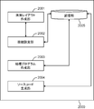
図12は、比較例のGUIビルダの構成を示すブロック図である。図12において、比較例のGUIビルダ2000は、画面レイアウト作成部2001、接続設定部2002、処理プログラム作成部2003、ソースコード生成部2004、及び記憶部2005を備えている。
(Background to obtaining the GUI program creation support apparatus according to the present embodiment)
FIG. 12 is a block diagram illustrating a configuration of a GUI builder according to a comparative example. 12, the GUI builder 2000 of the comparative example includes a screen layout creation unit 2001, a connection setting unit 2002, a processing program creation unit 2003, a source code generation unit 2004, and a storage unit 2005.
画面レイアウト作成部2001は、ユーザからの操作入力に基づき、GUIの画面レイアウトを生成する。接続設定部2002は、ユーザからの操作入力に基づき、画面レイアウトを構成するGUI部品に処理プログラムを関連付け、GUI部品と処理プログラムとの接続関係を示す接続情報を生成する。処理プログラム作成部2003は、プログラマの操作入力にしたがって、処理プログラムを作成する。ソースコード生成部2004は、画面レイアウト、処理プログラム、接続情報に基づき、GUIプログラムのソースコードを生成する。記憶部2005は画面レイアウト、処理プログラム、接続情報、GUIプログラムのソースコードを保存する。
The screen layout creation unit 2001 generates a GUI screen layout based on an operation input from the user. Based on an operation input from the user, the connection setting unit 2002 associates a processing program with a GUI component that constitutes the screen layout, and generates connection information indicating a connection relationship between the GUI component and the processing program. The processing program creation unit 2003 creates a processing program according to the operation input of the programmer. The source code generation unit 2004 generates a source code of the GUI program based on the screen layout, processing program, and connection information. A storage unit 2005 stores a screen layout, a processing program, connection information, and a source code of a GUI program.
しかしながら、図12に示すGUIビルダでは、処理プログラムが関連付けられた画面レイアウトを別の画面レイアウトに差し替えた場合、ユーザは、差替後の画面レイアウトを構成する各GUI部品に対し、処理プログラムを関連付ける作業を1つずつ行わなければならず、非常に手間がかかるという課題があった。
However, in the GUI builder shown in FIG. 12, when the screen layout associated with the processing program is replaced with another screen layout, the user associates the processing program with each GUI component constituting the screen layout after replacement. There was a problem that work had to be done one by one, which was very time consuming.
特に、差替前の画面レイアウトに多少の修正を加えて差替後の画面レイアウトが作成されることもあり、この場合、ユーザは、差替前の画面レイアウトにおいて行った作業とほとんど同じ作業を再度行わなければならず、多大な負担となっていた。
In particular, a screen layout after replacement may be created with some modifications to the screen layout before replacement. In this case, the user performs almost the same work as the work performed in the screen layout before replacement. It had to be done again, and it was a huge burden.
そこで、本実施の形態の目的は、画面レイアウトを差し替えて新たなGUIプログラムを開発する際の開発効率を向上させることができる技術を提供することである。
Therefore, an object of the present embodiment is to provide a technique capable of improving the development efficiency when developing a new GUI program by replacing the screen layout.
(本発明の実施の形態によるGUIプログラム作成支援装置の説明)
以下、本発明の実施の形態について、図面を参照しながら説明する。図1は、本発明の実施の形態におけるGUIプログラム作成支援装置100のブロック図である。GUIプログラム作成支援装置100は、中央演算装置と、ROM、RAM及びハードディスク等の記憶装置と、ディスプレイ等の出力装置と、キーボード等の入力装置とを備えるコンピュータにより構成されている。
(Description of GUI Program Creation Support Device According to Embodiment of the Present Invention)
Hereinafter, embodiments of the present invention will be described with reference to the drawings. FIG. 1 is a block diagram of a GUI program creation support apparatus 100 according to an embodiment of the present invention. The GUI program creation support apparatus 100 includes a computer including a central processing unit, storage devices such as ROM, RAM, and hard disk, an output device such as a display, and an input device such as a keyboard.
GUIプログラム作成支援装置100は、画面レイアウト作成部101、接続設定部102、処理プログラム作成部103、ソースコード生成部104、画面レイアウト比較部105、接続情報復帰部106、及び記憶部200を備えている。ここで、画面レイアウト作成部101~接続情報復帰部106は、例えばCPUにより実行されるプログラムモジュールにより構成される。
The GUI program creation support apparatus 100 includes a screen layout creation unit 101, a connection setting unit 102, a processing program creation unit 103, a source code generation unit 104, a screen layout comparison unit 105, a connection information return unit 106, and a storage unit 200. Yes. Here, the screen layout creation unit 101 to the connection information return unit 106 are constituted by program modules executed by the CPU, for example.
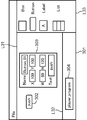
画面レイアウト作成部101は、ユーザからの操作入力に基づき、複数のGUI部品を含むGUIの画面レイアウトを生成する。図2は、画面レイアウト作成部101が画面レイアウトを生成する際にディスプレイに表示する入力画面301の一例を示す図である。画面レイアウト作成部101はこの入力画面301を通じてユーザからの操作入力を受け付ける。
The screen layout creation unit 101 generates a GUI screen layout including a plurality of GUI components based on an operation input from the user. FIG. 2 is a diagram illustrating an example of the input screen 301 displayed on the display when the screen layout creation unit 101 generates a screen layout. The screen layout creation unit 101 receives an operation input from the user through the input screen 301.
入力画面301は、作業エリアL31、プログラム配置エリアL32、及びGUI部品選択エリアL33を備えている。
The input screen 301 includes a work area L31, a program placement area L32, and a GUI part selection area L33.
作業エリアL31は、入力画面301の中央に設けられ、ユーザの操作入力に基づき、GUI部品302が配置される。作業エリアL31は画面レイアウトに対応しており、作業エリアL31の各位置が画面レイアウトの各位置となる。ここで、作業エリアL31は、水平方向(横方向)にX軸、垂直方向(縦方向)にY軸が規定され、X座標とY座標とで各位置が規定される。したがって、画面レイアウトの各位置も作業エリアL31におけるX座標とY座標とで表される。
The work area L31 is provided in the center of the input screen 301, and a GUI component 302 is arranged based on a user operation input. The work area L31 corresponds to the screen layout, and each position of the work area L31 becomes each position of the screen layout. Here, in the work area L31, the X axis is defined in the horizontal direction (lateral direction), the Y axis is defined in the vertical direction (longitudinal direction), and each position is defined by the X coordinate and the Y coordinate. Therefore, each position of the screen layout is also expressed by the X coordinate and the Y coordinate in the work area L31.
プログラム配置エリアL32は入力画面301の下部に設けられ、GUI部品に対して関連付けることができる処理プログラムを示すアイコン304を表示する。図2の例では、player_programと記述された1つのアイコン304が表示されている。なお、GUI部品に関連付けることができる処理プログラムが複数あれば、各処理プログラムのアイコン304がプログラム配置エリアL32に表示される。
The program placement area L32 is provided at the bottom of the input screen 301 and displays an icon 304 indicating a processing program that can be associated with the GUI component. In the example of FIG. 2, one icon 304 described as player_program is displayed. If there are a plurality of processing programs that can be associated with the GUI component, an icon 304 of each processing program is displayed in the program arrangement area L32.
GUI部品選択エリアL33は、入力画面の右側に設けられ、ユーザが選択可能な予め定められた複数のGUI部品を一覧表示する。図2の例では、GUI部品として、Box、Button、Label、及びListが含まれている。
The GUI component selection area L33 is provided on the right side of the input screen, and displays a list of predetermined GUI components that can be selected by the user. In the example of FIG. 2, Box, Button, Label, and List are included as GUI parts.
ユーザは、GUI部品選択エリアL33に表示されたGUI部品の中から好みのGUI部品を、例えばマウスをクリックして選択する。そして、選択したGUI部品を作業エリアL31にドラッグアンドドロップする。これにより、作成中の画面レイアウトにGUI部品が追加される。
The user selects a favorite GUI component from the GUI components displayed in the GUI component selection area L33 by, for example, clicking the mouse. Then, the selected GUI component is dragged and dropped onto the work area L31. As a result, the GUI component is added to the screen layout being created.
また、画面レイアウト作成部101は、GUI部品の属性を設定する機能を備える。GUI部品の属性としては、例えば名前、位置、大きさ、及び文字列が含まれる。名前の属性はGUI部品に付与される名前を定義する。位置の属性はGUI部品が配置される作業エリアL31における位置を定義する。文字列の属性はGUI部品に表示される文字列を定義する。
Further, the screen layout creation unit 101 has a function of setting attributes of GUI parts. As attributes of the GUI component, for example, a name, a position, a size, and a character string are included. The name attribute defines the name given to the GUI component. The position attribute defines the position in the work area L31 where the GUI component is arranged. The character string attribute defines a character string displayed on the GUI component.
図2において、作業エリアL31に表示されたGUI部品302が例えばマウスを用いてユーザによりダブルクリックされたとする。すると、画面レイアウト作成部101は、GUI部品302に隣接する位置にGUI部品302の属性を設定するための属性設定パネル303を表示する。
Suppose that the GUI component 302 displayed in the work area L31 in FIG. 2 is double-clicked by the user using a mouse, for example. Then, the screen layout creation unit 101 displays an attribute setting panel 303 for setting the attribute of the GUI component 302 at a position adjacent to the GUI component 302.
ユーザは、属性設定パネル303に設けられた各属性の入力欄に、属性値を入力することで、GUI部品302の属性を設定する。
The user sets the attribute of the GUI component 302 by inputting an attribute value in the input field of each attribute provided on the attribute setting panel 303.
図2の例では、属性設定パネル303において、“Name”の欄には名前の属性値が入力され、“X”、“Y”の欄には位置の属性値が入力され、“W”、“H”の欄には大きさの属性値が入力され、“Text”の欄には文字列の属性値が入力される。
In the example of FIG. 2, in the attribute setting panel 303, the name attribute value is input in the “Name” field, the position attribute value is input in the “X” and “Y” fields, and “W”, A size attribute value is input in the “H” field, and a character string attribute value is input in the “Text” field.
“Name”の欄には“Button_01”が記入されている。そのため、GUI部品302の名前の属性値は“Button_01”となる。
“Button_01” is entered in the “Name” column. Therefore, the attribute value of the name of the GUI component 302 is “Button_01”.
また、“X”、“Y”の欄にそれぞれ“100”、“100”が記入されている。そのため、GUI部品302の位置の属性値はX座標が100、Y座標が100となる。つまり、GUI部品302は、画面レイアウトにおいて(X,Y)=(100,100)の位置に配置される。
Also, “100” and “100” are entered in the “X” and “Y” columns, respectively. Therefore, the attribute value of the position of the GUI component 302 has an X coordinate of 100 and a Y coordinate of 100. That is, the GUI component 302 is arranged at the position (X, Y) = (100, 100) in the screen layout.
なお、ユーザは、作業エリアL31内において、マウスを操作してGUI部品302を移動させると、作業エリアL31内におけるGUI部品302の位置が“X”、“Y”の欄に反映される。つまり、ユーザは、“X”、“Y”の欄に直接属性値を入力する、或いは、GUI部品302をマウスで移動させることでGUI部品302の位置の属性値を設定することができる。
When the user moves the GUI part 302 by operating the mouse in the work area L31, the position of the GUI part 302 in the work area L31 is reflected in the “X” and “Y” columns. That is, the user can directly set the attribute value in the “X” and “Y” fields, or set the attribute value of the position of the GUI component 302 by moving the GUI component 302 with the mouse.
“W”、“H”の欄にはそれぞれ“50”、“120”が記入されている。よって、GUI部品302の大きさの属性値は、水平方向が“50”、垂直方向が“120”となる。この場合、GUI部品302は、50×120の矩形サイズを持つことになる。
“50” and “120” are entered in the “W” and “H” columns, respectively. Accordingly, the size attribute value of the GUI component 302 is “50” in the horizontal direction and “120” in the vertical direction. In this case, the GUI component 302 has a rectangular size of 50 × 120.
“Text”の欄には“push”が記入されている。そのため、GUI部品302の文字列の属性は、“push”となり、GUI部品302に“push”の文字列が重畳されている。
“Push” is entered in the “Text” column. Therefore, the attribute of the character string of the GUI component 302 is “push”, and the character string of “push” is superimposed on the GUI component 302.
画面レイアウト作成部101は、作業エリアL31にGUI部品を配置し、配置したGUI部品に対して属性を設定するユーザによる作業が終了すると、各GUI部品の属性が定義された画面レイアウト定義情報201を生成し、記憶部200に格納する。このように、画面レイアウト作成部101は、画面レイアウトが定義された画面レイアウト定義情報201を生成することで画面レイアウトを生成する。
The screen layout creation unit 101 arranges GUI parts in the work area L31, and when the user's work for setting attributes for the arranged GUI parts is finished, the screen layout definition information 201 in which the attributes of the GUI parts are defined is displayed. It is generated and stored in the storage unit 200. As described above, the screen layout creation unit 101 generates the screen layout by generating the screen layout definition information 201 in which the screen layout is defined.
画面レイアウト定義情報201は、例えばXML(eXtensible Markup Language)により記述される。図3は、画面レイアウト定義情報201の一例を示した図である。図3の例では、GUI部品302を含む画面レイアウトの画面レイアウト定義情報201が示されている。
The screen layout definition information 201 is described by XML (extensible Markup Language), for example. FIG. 3 is a diagram showing an example of the screen layout definition information 201. In the example of FIG. 3, screen layout definition information 201 of the screen layout including the GUI component 302 is shown.
GUI部品302は、ボタンの部品クラスに属している。そのため、図3の例では<class>のタグに“Button”と記述されている。ここで、部品クラスはGUI部品の種類を定義する。その他、部品クラスとして、ラベル、リスト、ボックスなどが存在する。よって、GUI部品の種類として、ボタンの他、ラベル、リスト、ボックスなどが存在する。
The GUI component 302 belongs to the button component class. Therefore, in the example of FIG. 3, “Button” is described in the tag of <class>. Here, the component class defines the type of GUI component. In addition, labels, lists, boxes, etc. exist as part classes. Therefore, there are labels, lists, boxes, etc. in addition to buttons as types of GUI parts.
また、GUI部品302は、位置の属性値が(X,Y)=(100,100)である。よって、<x>のタグに“100”と記述され、<y>のタグに100と記述されている。
Also, the GUI component 302 has a position attribute value (X, Y) = (100, 100). Therefore, “100” is described in the tag of <x>, and 100 is described in the tag of <y>.
また、GUI部品302は、大きさの属性値が(W,H)=(50,100)である。よって、<width>のタグに“50”と記述され、<height>のタグに“100”と記述されている。
The GUI component 302 has a size attribute value (W, H) = (50, 100). Therefore, “50” is described in the <width> tag, and “100” is described in the <height> tag.
また、GUI部品302は、文字列の属性値が“push”であるため、<text>のタグに“push”と記述されている。
Further, since the attribute value of the character string of the GUI component 302 is “push”, “push” is described in the <text> tag.
更に、画面レイアウト作成部101は、上記の作業により作成した画面レイアウトを、ユーザの操作入力に基づき、保存済みの画面レイアウトと差し替える機能を持つ。
Furthermore, the screen layout creation unit 101 has a function of replacing the screen layout created by the above operation with a saved screen layout based on a user operation input.
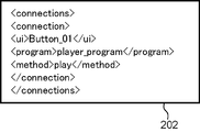
図1に戻り、接続設定部102は、ユーザの操作入力に基づき、GUI部品と処理プログラムとの関連付けを行い、当該関連付けを示す接続情報202を生成し、記憶部200に格納する。具体的には、接続設定部102は、ユーザが図2に示す作業エリアL31に配置されたGUI部品302をキーボードの特定のキーを押下した状態でマウスで選択し、図2に示すプログラム配置エリアL32に配置されたアイコン304に対してドラッグアンドドロップすると、図4に示す入力画面のディスプレイへの表示依頼を画面レイアウト作成部101に行う。
Referring back to FIG. 1, the connection setting unit 102 associates the GUI component with the processing program based on the user's operation input, generates connection information 202 indicating the association, and stores the connection information 202 in the storage unit 200. Specifically, the connection setting unit 102 selects the GUI component 302 arranged in the work area L31 shown in FIG. 2 with the mouse while pressing a specific key on the keyboard, and the program arrangement area shown in FIG. When dragging and dropping the icon 304 arranged in L32, the screen layout creation unit 101 is requested to display the input screen shown in FIG.
図4は、ユーザがGUI部品と処理プログラムとを関連付ける作業を行う際に表示される入力画面の一例を示した図である。
FIG. 4 is a diagram illustrating an example of an input screen displayed when the user performs an operation of associating the GUI component with the processing program.
図4の入力画面では、GUI部品302とアイコン304とが線分502で接続されている。そして、この線分502の中央から線分503が分岐し、線分503の先にメソッドリスト501が表示されている。
In the input screen of FIG. 4, the GUI component 302 and the icon 304 are connected by a line segment 502. A line segment 503 branches from the center of the line segment 502, and a method list 501 is displayed at the end of the line segment 503.
メソッドリスト501は、アイコン304で示される処理プログラム(player_program)が持つ複数のメソッドをリスト表示する。図4の例では、“play”、“stop”、“fforward”、“rewind”のメソッドが表示されている。ユーザはこれらのメソッドから1又は複数のメソッドを選択し、GUI部品302に処理プログラムを関連付ける。図4の例では、“play”のメソッドが黒丸で表示され、ユーザにより選択されている。この場合、接続設定部102は、player_programの“play”のメソッドをGUI部品302に関連付ける。このように、本実施の形態では、GUI部品に対し、処理プログラムを関連付けると共にその処理プログラムが含むいずれかのメソッドを関連付ける。
The method list 501 displays a list of a plurality of methods possessed by the processing program (player_program) indicated by the icon 304. In the example of FIG. 4, “play”, “stop”, “forward”, and “rewind” methods are displayed. The user selects one or more methods from these methods, and associates the processing program with the GUI component 302. In the example of FIG. 4, the “play” method is displayed as a black circle and is selected by the user. In this case, the connection setting unit 102 associates the “play” method of player_program with the GUI component 302. As described above, in the present embodiment, a processing program is associated with a GUI component and any method included in the processing program is associated.
図5は、接続情報202の一例を示した図である。図5に示すように、接続情報202は、例えばXMLにより記述されている。但し、これは一例であり、コンピュータが解釈可能な言語であればどのような言語を用いて記述してもよい。
FIG. 5 is a diagram showing an example of the connection information 202. As shown in FIG. 5, the connection information 202 is described in XML, for example. However, this is only an example, and any language can be used as long as it can be interpreted by a computer.
図5では、図2に示すGUI部品302に対する接続情報202が示されている。図5において、<ui>のタグにはGUI部品302の名前である“Button_01”が記述されている。<program>のタグには処理プログラムの名前である“player_program”が記述されている。これにより、GUI部品302に“player_program”の処理プログラムが関連付けられる。
FIG. 5 shows connection information 202 for the GUI component 302 shown in FIG. In FIG. 5, “Button_01” that is the name of the GUI component 302 is described in a tag of <ui>. In the <program> tag, “player_program”, which is the name of the processing program, is described. As a result, the processing program “player_program” is associated with the GUI component 302.
また、<method>のタグには、処理プログラムのうち関連付けられたメソッド名である“play”が記述されている。これにより、GUI部品302に、“play”メソッドが関連付けられる。
In the <method> tag, “play”, which is an associated method name in the processing program, is described. As a result, the “play” method is associated with the GUI component 302.
本実施の形態では、接続情報202は、例えばGUI部品毎に生成され、記憶部200に格納される。そして、接続情報202は、GUI部品の名前の属性値が記述されている。したがって、GUI部品302の名前の属性値をキーとして、GUI部品302の接続情報202を特定することができ、GUI部品に関連付けられた処理プログラムを特定することができる。
In the present embodiment, the connection information 202 is generated for each GUI component and stored in the storage unit 200, for example. The connection information 202 describes the attribute value of the name of the GUI component. Therefore, the connection information 202 of the GUI component 302 can be specified using the attribute value of the name of the GUI component 302 as a key, and the processing program associated with the GUI component can be specified.
処理プログラム作成部103は、ユーザの操作入力に基づき、GUI部品が操作された際に実行される処理に係る処理プログラム203を作成する。具体的には、処理プログラム作成部103は、例えばテキストエディタにより構成され、処理プログラム203の作成および編集を行う。作成された処理プログラム203は記憶部200に保存される。
The processing program creation unit 103 creates a processing program 203 related to processing executed when a GUI component is operated based on a user operation input. Specifically, the processing program creation unit 103 is configured by a text editor, for example, and creates and edits the processing program 203. The created processing program 203 is stored in the storage unit 200.
処理プログラム203は、例えばJavaScript(登録商標)等により記述され、少なくとも1個以上のメソッドを備えている。図6は、処理プログラム203の一例を示した図である。
The processing program 203 is described by, for example, JavaScript (registered trademark) or the like, and includes at least one method. FIG. 6 is a diagram illustrating an example of the processing program 203.
図6の例では、図4に示す“player_program”の処理プログラム203が示されている。図6の1行目において、“player_program”と記述され、“player_program”が宣言されている。
In the example of FIG. 6, the processing program 203 of “player_program” shown in FIG. 4 is shown. In the first line of FIG. 6, “player_program” is described and “player_program” is declared.
図4に示すように、“player_program”は、“play”、“stop”、“fforward”、“rewind”のメソッドを備えている。したがって、図6の3~6行目の各行においてこれらのメソッドが定義されている。図6の例では、各メソッドの詳細なプログラムコードは省略されている。
As shown in FIG. 4, “player_program” has “play”, “stop”, “forward”, and “rewind” methods. Therefore, these methods are defined in each of the third to sixth lines in FIG. In the example of FIG. 6, the detailed program code of each method is omitted.
なお、処理プログラム203を作成するユーザは主にプログラマを想定しており、画面レイアウトを作成するデザイナとは別のユーザであることを想定している。
It should be noted that the user who creates the processing program 203 is mainly assumed to be a programmer, and is assumed to be a user other than the designer who creates the screen layout.
なお、メソッドを実行する機器は、GUIを表示する機器と異なっていてもよい。すなわち、GUIを表示する機器が、例えば、ネットワークを介してサーバと接続されている場合、ユーザによりGUI部品が操作されると、機器はGUI部品の操作情報をサーバに通知する。そして、サーバは、その操作情報からGUI部品に関連付けられたメソッドを実行し、処理結果を機器に返すようにしてもよい。
Note that the device that executes the method may be different from the device that displays the GUI. That is, when a device that displays a GUI is connected to a server via a network, for example, when the user operates the GUI component, the device notifies the server of operation information of the GUI component. Then, the server may execute a method associated with the GUI component from the operation information and return the processing result to the device.
この場合、GUIが実装された機器は処理プログラム203を実装していなくてもよくなる。このように、処理プログラム203はGUIが実装された機器と同一の機器に存在させてもよいし、ネットワークで接続された異なる機器に存在させていてもよい。
In this case, the device on which the GUI is mounted does not have to be mounted with the processing program 203. In this way, the processing program 203 may exist in the same device as the device on which the GUI is installed, or may exist in a different device connected via a network.
ソースコード生成部104は、画面レイアウト定義情報201、接続情報202、及び処理プログラム203に基づいて、GUIプログラムのソースコード204を作成する。作成されたソースコード204は、記憶部200に保存される。ソースコード204は、例えばJava(登録商標)Scriptにより記述される。
The source code generation unit 104 creates the source code 204 of the GUI program based on the screen layout definition information 201, the connection information 202, and the processing program 203. The created source code 204 is stored in the storage unit 200. The source code 204 is described by, for example, Java (registered trademark) Script.
なお、画面レイアウト作成部101は、処理プログラムを実装する機器と異なる機器に画面レイアウトが存在するよう画面レイアウトの設定を変更することができる。この場合、ソースコード生成部104は、画面レイアウト上のGUI部品がネットワークを経由して処理プログラム203を実装する機器にアクセスするソースコード204を生成する。
Note that the screen layout creation unit 101 can change the screen layout setting so that the screen layout exists on a device different from the device on which the processing program is installed. In this case, the source code generation unit 104 generates source code 204 for accessing a device on which the GUI component on the screen layout mounts the processing program 203 via the network.
図7は、ソースコード204の一例を示した図である。図7の例では、GUI部品302に対するソースコード204が示されている。
FIG. 7 is a diagram showing an example of the source code 204. In the example of FIG. 7, source code 204 for the GUI component 302 is shown.
1行目にボタンの部品クラスに属するオブジェクトである“button1”が宣言されている。2行目に“button1.setProgram(player_program)”と記述され、“button1”のオブジェクトに“player_program”が関連付けられている。
In the first line, “button1”, which is an object belonging to the button component class, is declared. “Button1.setProgram (player_program)” is described in the second line, and “player_program” is associated with the object of “button1”.
3行目に、“button1.setProgramMethod(“play”)”と記述され、button1のオブジェクトに“play”のメソッドが関連付けられている。
In the third line, “button1.setProgrammethod (“ play ”)” is described, and the “play” method is associated with the button1 object.
よって、ソースコード204を実装する機器は、GUI部品302が操作されると、player_programの“play”のメソッドを実行する。
Therefore, when the GUI component 302 is operated, the device on which the source code 204 is mounted executes the “play” method of the player_program.
このように、ソースコード生成部104は、画面レイアウト定義情報201を解析して、画面レイアウト上の各GUI部品の種類や表示位置を示す属性を抽出し、GUI部品毎のソースコード204を生成して、生成したソースコード204に抽出した属性を登録する。なお、図7の例では、GUI部品の属性の記述は省略されている。また、ソースコード生成部104は、接続情報202を解析し、各GUI部品に関連付けられている処理プログラム203及びのメソッドを抽出する。そして、ソースコード生成部104は、GUI部品にイベント(例えば、ユーザが部品のGUI部品を押す等のイベント)が発生したとき、GUI部品に関連付けられた処理プログラム203及びメソッドを呼び出すためのコードをソースコード204に記述する。これにより、GUI部品にイベントが発生した場合、ソースコード204が解釈されて、関連付けられた処理プログラムのメソッドが実行される。
As described above, the source code generation unit 104 analyzes the screen layout definition information 201, extracts attributes indicating the type and display position of each GUI component on the screen layout, and generates the source code 204 for each GUI component. Thus, the extracted attribute is registered in the generated source code 204. In the example of FIG. 7, the description of the attribute of the GUI component is omitted. Further, the source code generation unit 104 analyzes the connection information 202 and extracts the processing program 203 and the method associated with each GUI component. Then, the source code generation unit 104 generates a code for calling a processing program 203 and a method associated with the GUI component when an event (for example, an event such as a user pressing the GUI component of the component) occurs in the GUI component. Described in the source code 204. As a result, when an event occurs in the GUI component, the source code 204 is interpreted and the method of the associated processing program is executed.
本実施の形態では、ソースコード204は、GUI部品毎に生成され、画面レイアウト単位で1ファイルにまとめられる。
In the present embodiment, the source code 204 is generated for each GUI component and is combined into one file for each screen layout.
図1に戻り、記憶部200は、例えばHDD(ハードディスクドライブ)により構成され、画面レイアウト定義情報201、接続情報202、処理プログラム203、及びソースコード204を保存する。
Returning to FIG. 1, the storage unit 200 is configured by, for example, an HDD (hard disk drive), and stores screen layout definition information 201, connection information 202, a processing program 203, and source code 204.
画面レイアウト比較部105は、画面レイアウト作成部101により、生成済の画面レイアウトが別の画面レイアウトに差し替えられた場合、差替後画面レイアウトのGUI部品に類似するGUI部品を、差替前画面レイアウトから推測し、類似するGUI部品同士を対応付ける。この推測の詳細については後述する。
When the generated screen layout is replaced with another screen layout by the screen layout creating unit 101, the screen layout comparing unit 105 displays a GUI component similar to the GUI component of the post-replacement screen layout. And similar GUI parts are associated with each other. Details of this estimation will be described later.
接続情報復帰部106は、差替前画面レイアウトのGUI部品に関連付けられた処理プログラムを、画面レイアウト比較部105により対応付けられたGUI部品に関連付ける接続復帰処理を行う。
The connection information return unit 106 performs a connection return process that associates the processing program associated with the GUI component of the pre-replacement screen layout with the GUI component associated with the screen layout comparison unit 105.
従来のGUIビルダにおいては、生成済の画面レイアウトを差し替えて別の画面レイアウトを作成する場合、ユーザは差替後画面レイアウトの各GUI部品に対して処理プログラムを関連付ける作業を一個ずつ手作業で行わなければならなかった。
In the conventional GUI builder, when the generated screen layout is replaced to create another screen layout, the user manually associates the processing program with each GUI component of the replaced screen layout one by one. I had to.
差替後画面レイアウトは、例えば、差替前画面レイアウトの一部のGUI部品を削除したり、差替前画面レイアウトに新たなGUI部品を追加したり、差替前画面レイアウトのGUI部品の位置を変更したりというようにして作成されることが多い。よって、差替後画面レイアウトは差替前画面レイアウトに対して多くのGUI部品が共通している可能性が高い。したがって、従来のGUIビルダのように差替後画面レイアウトの各GUI部品のそれぞれに対して、処理プログラムを関連付ける作業をユーザに課してしまうと、ユーザへの負担が重くなってしまう。
The screen layout after replacement may be, for example, deleting some GUI parts of the screen layout before replacement, adding a new GUI part to the screen layout before replacement, or the position of the GUI part of the screen layout before replacement. It is often created by changing the Therefore, the post-replacement screen layout is likely to have many GUI components in common with the pre-replacement screen layout. Therefore, if the user associates the processing program with each GUI component of the post-replacement screen layout as in the conventional GUI builder, the burden on the user becomes heavy.
そこで、本実施の形態では、差替後画面レイアウトの各GUI部品につき、類似するGUI部品を差替前画面レイアウトの中から推測し、類似するGUI部品があると推測された差替後画面レイアウトのGUI部品については、類似するGUI部品に関連付けられた処理プログラムを自動的に関連付ける。
Therefore, in the present embodiment, for each GUI component in the post-replacement screen layout, a similar GUI component is estimated from the pre-replacement screen layout, and the post-replacement screen layout is estimated to have a similar GUI component. For the GUI parts, a processing program associated with a similar GUI part is automatically associated.
そのため、ユーザは差替後画面レイアウトにつき、処理プログラムを関連付ける作業を行う手間が軽減され、GUIの画面レイアウトの開発効率を大幅に増大させることができる。
Therefore, the user can save time and effort for associating the processing program with the screen layout after replacement, and the development efficiency of the GUI screen layout can be greatly increased.
具体的には、接続情報復帰部106は、接続復帰処理を行った差替後画面レイアウトのGUI部品の名前の属性値を、対応する差替前画面レイアウトのGUI部品の名前の属性値で更新する。例えば、差替後画面レイアウトのGUI部品につき、名前の属性値が“Button_01”であり、差替前画面レイアウトのGUI部品につき、名前の属性値が“Button_A”であったとすると、差替後画面レイアウトのGUI部品の名前の属性値が“Button_A”とされる。
Specifically, the connection information return unit 106 updates the attribute value of the name of the GUI part of the post-replacement screen layout that has undergone the connection return process with the attribute value of the name of the GUI part of the corresponding pre-replacement screen layout. To do. For example, if the attribute value of the name is “Button_01” for the GUI component of the screen layout after replacement, and the attribute value of the name is “Button_A” for the GUI component of the screen layout before replacement, the screen after replacement The attribute value of the name of the GUI component of the layout is “Button_A”.
これにより、差替前画面レイアウトのGUI部品に関連付けられていた処理プログラム及びメソッドが差替後画面レイアウトのGUI部品に関連付けられる。
Thereby, the processing program and method associated with the GUI component of the screen layout before replacement are associated with the GUI component of the screen layout after replacement.
つまり、差替後画面レイアウトのGUI部品の接続情報202及びソースコード204は、差替前画面レイアウトのGUI部品の名前の属性値である“Button_A”をキーとして差替前画面レイアウトの画面レイアウト定義情報201と関連付けられている。よって、差替後画面レイアウトのGUI部品の名前の属性値を差替前画面レイアウトのGUI部品の名前の属性値で更新すると、差替後画面レイアウトのGUI部品の接続情報202及びソースコード204を新たに生成することなく、差替後画面レイアウトのGUI部品に差替前画面レイアウトのGUI部品の処理プログラム及びメソッドを関連付けることができる。
That is, the connection information 202 and the source code 204 of the GUI part of the screen layout after replacement define the screen layout of the screen layout before replacement using “Button_A” that is the attribute value of the name of the GUI part of the screen layout before replacement as a key. Associated with information 201. Therefore, when the attribute value of the name of the GUI part of the screen layout after replacement is updated with the attribute value of the name of the GUI part of the screen layout before replacement, the connection information 202 and the source code 204 of the GUI part of the screen layout after replacement are updated. The processing program and method of the GUI component of the screen layout before replacement can be associated with the GUI component of the screen layout after replacement without newly generating.
また、接続情報復帰部106は、画面レイアウト比較部105により対応付けられたGUI部品をユーザに報知し、推測結果が正しいことを示す操作入力がユーザにより行われたGUI部品について、接続復帰処理を行う。
In addition, the connection information return unit 106 notifies the user of the GUI component associated by the screen layout comparison unit 105, and performs connection return processing on the GUI component for which an operation input indicating that the estimation result is correct is performed by the user. Do.
例えば、差替後画面レイアウトのGUI部品に対して、ユーザが想定するGUI部品とは別のGUI部品が類似すると推測されることもある。この場合、接続復帰処理が自動的に実行されてしまうと、ユーザは関連付けを解除し、差替後画面レイアウトのGUI部品に再度、希望する処理プログラム及びメソッドを関連付ける作業を行う必要がある。これでは、却って、ユーザの作業効率を低下させてしまう。
For example, it may be presumed that a GUI component different from the GUI component assumed by the user is similar to the GUI component of the screen layout after replacement. In this case, when the connection return process is automatically executed, the user needs to cancel the association and associate the desired processing program and method again with the GUI component of the post-replacement screen layout. This, on the contrary, reduces the user's work efficiency.
そこで、推測結果が正しいか否かをユーザに問い合わせる構成を採用する。これにより、推測結果が正しいか否かをユーザに事前に判断させることができ、差替後画面レイアウトのGUI部品に対してユーザが意図しない処理プログラムが関連付けられることを防止し、作業効率の向上を図ることができる。
Therefore, a configuration is adopted in which the user is inquired whether the estimation result is correct. This allows the user to determine in advance whether or not the estimation result is correct, prevents the processing program unintended by the user from being associated with the GUI component of the post-replacement screen layout, and improves work efficiency. Can be achieved.
問い合わせの形態としては、差替後画面レイアウトのGUI部品の名前の属性値と差替前画面レイアウトのGUI部品の名前の属性値とを対応付けて示し、かつ、“正しい”又は“正しくない”の選択項目を含むダイアログボックスをディスプレイに表示すればよい。そして、このダイアログボックスをGUI部品の数だけ繰り返し表示するようにすればよい。
As an inquiry form, the attribute value of the name of the GUI part of the screen layout after replacement is associated with the attribute value of the name of the GUI part of the screen layout before replacement, and is “correct” or “incorrect”. A dialog box containing the selected items may be displayed on the display. Then, this dialog box may be repeatedly displayed by the number of GUI parts.
或いは、全GUI部品の対応付けをリスト表示し、かつ、各対応付けにつき、“正しい”又は“正しくない”の選択項目を含む1枚のダイアログボックスをディスプレイに表示してもよい。或いは、差替前画面レイアウトと差替後画面レイアウトとを並べて表示し、GUI部品の対応付けをGUI部品間を結ぶ線分で表現し、かつ正しくない対応付けの線分をユーザ操作により削除するようにしてもよい。
Alternatively, a list of all GUI component associations may be displayed, and a single dialog box including a selection item of “correct” or “incorrect” may be displayed on the display for each association. Alternatively, the pre-replacement screen layout and the post-replacement screen layout are displayed side by side, the GUI component association is represented by a line segment connecting the GUI components, and the incorrect association line segment is deleted by a user operation. You may do it.
以上がGUIプログラム作成支援装置100の構成についての説明である。
This completes the description of the configuration of the GUI program creation support apparatus 100.
(フローチャート)
以下、本実施の形態におけるGUIプログラム作成支援装置100が行う処理を説明する。図9は、本発明の実施の形態に係るGUIプログラム作成支援装置100が行う、GUIプログラムの作成処理を示すフローチャートである。
(flowchart)
Hereinafter, processing performed by the GUI program creation support apparatus 100 according to the present embodiment will be described. FIG. 9 is a flowchart showing a GUI program creation process performed by the GUI program creation support apparatus 100 according to the embodiment of the present invention.
まず、処理プログラム作成部103は、ユーザからの操作入力に基づき、図6に示すような、GUI部品に対する処理プログラム203を作成する(S1001)。作成された処理プログラム203は記憶部200に保存される。処理プログラム203が保存されると、処理プログラム203を示すアイコン304が、図2に示すプログラム配置エリアL32に表示される。
First, the processing program creation unit 103 creates a processing program 203 for a GUI component as shown in FIG. 6 based on an operation input from the user (S1001). The created processing program 203 is stored in the storage unit 200. When the processing program 203 is saved, an icon 304 indicating the processing program 203 is displayed in the program arrangement area L32 shown in FIG.
次に、画面レイアウト作成部101は、ユーザからの操作入力に基づき、GUI部品を配置し、画面レイアウトを作成する(S1002)。この場合、各GUI部品には、一意に名前の属性値が設定される。この名前の属性値は、画面レイアウト作成部101が自動的に付加してもよいし、ユーザが指定してもよい。画面レイアウト作成部101が自動的に付加する態様としては、例えば、GUI部品がボタンの部品クラスに属し、1個目のボタンのGUI部品であれば“Button_01”、2個目のボタンのGUI部品であれば“Button_02”、というように、クラスやラベルを示す文字列と作成順序を示す数値との組からなる名前の属性値を付与すればよい。
Next, the screen layout creation unit 101 arranges GUI parts based on the operation input from the user, and creates a screen layout (S1002). In this case, a unique attribute value is set for each GUI component. The attribute value of this name may be automatically added by the screen layout creation unit 101 or may be specified by the user. For example, if the GUI component belongs to the button component class and the GUI component of the first button is “Button_01”, the GUI component of the second button is automatically added by the screen layout creation unit 101. If so, an attribute value of a name consisting of a combination of a character string indicating a class or a label and a numerical value indicating a creation order may be given, such as “Button_02”.
そして、画面レイアウト作成部101は、ユーザによる画面レイアウトの作成作業が終了すると、画面レイアウトを定義する画面レイアウト定義情報201を生成し、記憶部200に保存する。これにより、画面レイアウトが記憶部200に保存される。この場合、画面レイアウト作成部101は、ユーザに画面レイアウト定義情報201のファイル名を入力させ、このファイル名を持つ画面レイアウト定義情報201を記憶部200に保存させればよい。
Then, when the user finishes creating the screen layout, the screen layout creating unit 101 generates screen layout definition information 201 that defines the screen layout and stores it in the storage unit 200. As a result, the screen layout is stored in the storage unit 200. In this case, the screen layout creation unit 101 may cause the user to input the file name of the screen layout definition information 201 and store the screen layout definition information 201 having this file name in the storage unit 200.
これにより、ユーザはファイル名を指定することで、指定したファイル名を持つ画面レイアウト定義情報201で定義された作成済みの画面レイアウトをディスプレイに表示することができる。
Thus, the user can display the created screen layout defined in the screen layout definition information 201 having the specified file name on the display by specifying the file name.
そして、画面レイアウト作成部101は、ユーザにより作成済みの画面レイアウトが編集された場合、編集作業が終了したとき、編集後の画面レイアウトの画面レイアウト定義情報201を生成し、元の画面レイアウト定義情報201に上書き保存させればよい。
Then, when the screen layout created by the user is edited, the screen layout creation unit 101 generates screen layout definition information 201 of the screen layout after editing when the editing operation is completed, and the original screen layout definition information 201 may be overwritten and saved.
図8(A)は画面レイアウト作成部101により作成された画面レイアウト900の一例を示す図である。以後、図8(A)の画面レイアウト900を差替前画面レイアウトとして説明する。
FIG. 8A is a diagram showing an example of the screen layout 900 created by the screen layout creation unit 101. Hereinafter, the screen layout 900 of FIG. 8A will be described as a pre-replacement screen layout.
次に、接続設定部102は、ユーザの操作入力に基づき、画面レイアウト作成部101により作成された画面レイアウト900を構成するGUI部品に対し、処理プログラム203を関連付ける(S1003)。
Next, the connection setting unit 102 associates the processing program 203 with the GUI parts constituting the screen layout 900 created by the screen layout creating unit 101 based on the user's operation input (S1003).
図8(A)の例では、GUI部品901はボタンクラスのGUI部品であり、ユーザにより処理プログラム203の“play”メソッドが関連付けられている。したがって、接続設定部102は、GUI部品901に処理プログラム203の“play”メソッドを関連付けた接続情報202を生成する。
In the example of FIG. 8A, the GUI component 901 is a GUI component of a button class, and the “play” method of the processing program 203 is associated with the user. Therefore, the connection setting unit 102 generates the connection information 202 in which the “play” method of the processing program 203 is associated with the GUI component 901.
接続設定部102は、他のGUI部品902~904についても、同様に処理プログラム203との関連付けを行い、接続情報202を生成する。生成された接続情報202は記憶部200に保存される。
The connection setting unit 102 similarly associates the other GUI components 902 to 904 with the processing program 203 to generate connection information 202. The generated connection information 202 is stored in the storage unit 200.
次に、ソースコード生成部104は、各GUI部品に関連付けられた処理プログラム203と、画面レイアウト910を定義する画面レイアウト定義情報201と、接続情報202との記述内容に基づき、図7に示すようなGUIプログラムのソースコード204を生成する(S1004)。生成されたソースコード204は記憶部200に保存される。
Next, the source code generation unit 104, based on the description contents of the processing program 203 associated with each GUI component, the screen layout definition information 201 that defines the screen layout 910, and the connection information 202, as shown in FIG. A source code 204 of the GUI program is generated (S1004). The generated source code 204 is stored in the storage unit 200.
なお、処理プログラム203は、GUIプログラムを起動する時点で機器により読み込まれて利用可能となる。そのため、ソースコード204では明示的な初期化処理は定義されていない。しかしながら、ソースコード204において、初期化処理を明示的に定義した場合は、処理プログラム203には処理プログラムの定義のみを記述し、ソースコード204中で処理プログラム203の初期化処理を行うようにしてもよい。
Note that the processing program 203 is read and used by the device when the GUI program is started. Therefore, an explicit initialization process is not defined in the source code 204. However, when the initialization process is explicitly defined in the source code 204, only the definition of the processing program is described in the processing program 203, and the initialization process of the processing program 203 is performed in the source code 204. Also good.
以上が、GUIプログラムの作成処理である。
The above is the process of creating the GUI program.
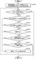
次に、画面レイアウトを差し替える際の処理について説明する。図10は、画面レイアウトを差し替える際の処理を示すフローチャートである。
Next, the process when the screen layout is replaced will be described. FIG. 10 is a flowchart showing processing when the screen layout is replaced.
まず、画面レイアウト作成部101は、S1002と同様の方法で画面レイアウト900とは異なる画面レイアウト910を作成する(S2100)。そして、画面レイアウト910を定義する画面レイアウト定義情報201を作成し、記憶部200に保存する。ここで、一旦、画面レイアウト作成部101は、画面レイアウト910の作成処理を終了する。図8(B)は画面レイアウト910の一例を示す図である。以後、画面レイアウト910を差替後画面レイアウトとして説明する。
First, the screen layout creating unit 101 creates a screen layout 910 different from the screen layout 900 in the same manner as in S1002 (S2100). Then, screen layout definition information 201 that defines the screen layout 910 is created and stored in the storage unit 200. Here, the screen layout creation unit 101 once ends the screen layout 910 creation processing. FIG. 8B is a diagram illustrating an example of the screen layout 910. Hereinafter, the screen layout 910 will be described as a post-replacement screen layout.
次に、画面レイアウト作成部101は、ユーザの操作入力に基づき、画面レイアウト900を画面レイアウト910に差し替える(S2200)。
Next, the screen layout creation unit 101 replaces the screen layout 900 with the screen layout 910 based on a user operation input (S2200).
具体的には、画面レイアウト作成部101は、画面レイアウト910がディスプレイに表示された状態において、ユーザから画面レイアウトの差し替えの指示を受け付ける。すると、画面レイアウト作成部101は、記憶部200に保存されている画面レイアウト定義情報201のファイル名をリスト表示させる。そして、ユーザに1つの画面レイアウト定義情報201が選択されると、画面レイアウト作成部101は、選択された画面レイアウト定義情報201によって定義された画面レイアウト900を差替前画面レイアウトとしてディスプレイに表示する。
Specifically, the screen layout creation unit 101 receives an instruction to replace the screen layout from the user in a state where the screen layout 910 is displayed on the display. Then, the screen layout creation unit 101 displays a list of file names of the screen layout definition information 201 stored in the storage unit 200. When one screen layout definition information 201 is selected by the user, the screen layout creation unit 101 displays the screen layout 900 defined by the selected screen layout definition information 201 on the display as the pre-replacement screen layout. .
そして、画面レイアウト作成部101は、ユーザに画面レイアウト900を画面レイアウト910で差し替えて良いか否かを問い合わせるダイアログボックスをディスプレイに表示する。そして、ユーザにより差し替えて良いことを示す操作入力が行われると、画面レイアウト作成部101は、画面レイアウト900を画面レイアウト910の差し替え対象の画面レイアウトとして認識する。一方、ユーザにより差し替えては良くないことを示す操作入力が行われると、画面レイアウト作成部101は、再度、画面レイアウト定義情報201のファイル名をリスト表示し、別の画面レイアウトの選択をユーザに促せばよい。
Then, the screen layout creation unit 101 displays a dialog box on the display asking whether the user can replace the screen layout 900 with the screen layout 910. When an operation input indicating that the user can replace the screen is performed, the screen layout creation unit 101 recognizes the screen layout 900 as a screen layout to be replaced with the screen layout 910. On the other hand, when an operation input indicating that the replacement is not allowed is performed by the user, the screen layout creation unit 101 displays a list of file names of the screen layout definition information 201 again and allows the user to select another screen layout. Just ask.
そして、画面レイアウト作成部101は、画面レイアウト910の差し替え対象となる画面レイアウト900を認識すると、再度、画面レイアウト910をディスプレイに表示する。
Then, when the screen layout creation unit 101 recognizes the screen layout 900 to be replaced with the screen layout 910, the screen layout 910 is displayed again on the display.
次に、画面レイアウト比較部105は、画面レイアウト900と画面レイアウト910との比較を行い、画面レイアウト910を構成するGUI部品に対して類似するGUI部品を画面レイアウト900の中から推測する(S2300)。ここで、画面レイアウト比較部105は、類似するGUI部品同士を対応付け、推測データに記述し、記憶部200に格納する。
Next, the screen layout comparison unit 105 compares the screen layout 900 with the screen layout 910, and estimates a GUI component similar to the GUI component constituting the screen layout 910 from the screen layout 900 (S2300). . Here, the screen layout comparison unit 105 associates similar GUI components with each other, describes them in the estimation data, and stores them in the storage unit 200.
次に、接続情報復帰部106は、画面レイアウト比較部105により生成された推測データから、画面レイアウト910のGUI部品に対し、類似すると推測されたGUI部品が画面レイアウト900に存在するか否かを判定する(S2400)。そして、接続情報復帰部106は、類似するGUI部品が存在すると判定した場合(S2400でYES)、処理をS2500に進め、類似するGUI部品が存在しないと判定した場合(S2400でNO)処理を終了する。
Next, the connection information return unit 106 determines whether or not a GUI component that is estimated to be similar to the GUI component of the screen layout 910 exists in the screen layout 900 from the estimated data generated by the screen layout comparison unit 105. Determination is made (S2400). If the connection information return unit 106 determines that there is a similar GUI component (YES in S2400), the process proceeds to S2500. If it is determined that there is no similar GUI component (NO in S2400), the process ends. To do.
次に、接続情報復帰部106は、類似するGUI部品が存在すると推測された画面レイアウト910のGUI部品の名前の属性値を類似するGUI部品の名前の属性値で更新する(S2500)。これにより、画面レイアウト900のGUI部品の処理プログラム及びメソッドが、対応する画面レイアウト910のGUI部品に関連付けられる。
Next, the connection information return unit 106 updates the attribute value of the name of the GUI component of the screen layout 910 that is estimated to have a similar GUI component with the attribute value of the name of the similar GUI component (S2500). As a result, the GUI component processing program and method of the screen layout 900 are associated with the corresponding GUI component of the screen layout 910.
例えば、GUI部品901とGUI部品911とが類似すると推測され、GUI部品911の名前の属性値が“Button_01”、GUI部品901の名前の属性値が“Button_A”であったとする。この場合、接続情報復帰部106は、画面レイアウト910のGUI部品911の名前の属性値を“Button_01”から“Button_A”に更新する。
For example, it is assumed that the GUI component 901 and the GUI component 911 are similar, the attribute value of the name of the GUI component 911 is “Button_01”, and the attribute value of the name of the GUI component 901 is “Button_A”. In this case, the connection information return unit 106 updates the attribute value of the name of the GUI component 911 of the screen layout 910 from “Button_01” to “Button_A”.
なお、接続情報復帰部106は、GUI部品911以外の画面レイアウト910を構成するGUI部品912~914についても、類似するGUI部品が画面レイアウト900に存在すれば、GUI部品911と同様にして、名前の属性値を対応するGUI部品の名前の属性値で更新する。
It should be noted that the connection information return unit 106 uses the same name for the GUI components 912 to 914 constituting the screen layout 910 other than the GUI component 911 as long as similar GUI components exist in the screen layout 900, as in the GUI component 911. Is updated with the attribute value of the name of the corresponding GUI part.
また、S2500において、接続情報復帰部106は、GUI部品の名前の属性値を更新した結果、他のGUI部品と名前の属性値が重複した場合は、重複したGUI部品の名前を適宜変更すればよい。
In S2500, if the attribute information of the name of the GUI component is updated and the attribute value of the name is duplicated as a result of updating the GUI component name attribute value in S2500, the connection information return unit 106 may change the name of the duplicate GUI component appropriately. Good.
例えば、GUI部品911の名前の属性値を“Button_A”に更新したが、画面レイアウト910において、GUI部品912の名前の属性値が“Button_A”であったとする。
For example, it is assumed that the attribute value of the name of the GUI component 911 is updated to “Button_A”, but the attribute value of the name of the GUI component 912 is “Button_A” in the screen layout 910.
この場合、接続情報復帰部106は、GUI部品911の名前の属性値を“Button_A”とは別の属性値(例えば、“Button_A’”)に変更してもよいし、GUI部品912の名前の属性値を“Button_A”から“Button_A’”に変更してもよい。
In this case, the connection information return unit 106 may change the attribute value of the name of the GUI component 911 to an attribute value different from “Button_A” (for example, “Button_A ′”), or the name of the GUI component 912 The attribute value may be changed from “Button_A” to “Button_A ′”.
なお、GUI部品911の名前の属性値を“Button_A’”とする場合、画面レイアウト900のGUI部品901の名前の属性値を“Button_A”から“Button_A’”に変更し、GUI部品901の接続情報202及びソースコード204のキーを“Button_A”から“Button_A’”に変更する。こうすることで、GUI部品901と処理プログラム203との関連づけが切れることを防止することができる。
When the attribute value of the name of the GUI component 911 is “Button_A ′”, the attribute value of the name of the GUI component 901 in the screen layout 900 is changed from “Button_A” to “Button_A ′”, and the connection information of the GUI component 901 is displayed. 202 and the key of the source code 204 are changed from “Button_A” to “Button_A ′”. By doing so, it is possible to prevent the association between the GUI component 901 and the processing program 203 from being disconnected.
なお、S2500において、接続情報復帰部106は、名前の属性値が更新されるGUI部品の候補をユーザに提示し、実際に名前の属性値を更新するか否かをユーザに問い合わせてもよい。
In S2500, the connection information return unit 106 may present a GUI component candidate whose name attribute value is updated to the user and inquire the user whether or not to actually update the name attribute value.
また、S2400において類似するGUI部品が存在しなかった場合(S2400でNO)、接続情報復帰部106は、画面レイアウト900と画面レイアウト910とを表示し、画面レイアウト910のGUI部品に類似する画面レイアウト900のGUI部品をユーザに指定させるようにしてもよい。この場合、接続情報復帰部106は、画面レイアウト910のGUI部品の名前の属性値をユーザが指定した画面レイアウト900のGUI部品の名前の属性値で更新すればよい。こうすることで、画面レイアウト910のGUI部品に対してユーザが指定したGUI部品の処理プログラム及びメソッドが関連付けられる。
If no similar GUI component exists in S2400 (NO in S2400), the connection information return unit 106 displays the screen layout 900 and the screen layout 910, and the screen layout similar to the GUI component of the screen layout 910 is displayed. 900 GUI components may be specified by the user. In this case, the connection information return unit 106 may update the attribute value of the GUI part name of the screen layout 910 with the attribute value of the name of the GUI part of the screen layout 900 specified by the user. By doing so, the GUI component processing program and method designated by the user are associated with the GUI component of the screen layout 910.
以上が、画面レイアウトを差し替える際の処理である。
The above is the process for replacing the screen layout.
続いて、画面レイアウト900と画面レイアウト910とを比較する処理の詳細について説明する。図11は、図10におけるS2300のサブルーチンを示すフローチャートである。
Next, details of the process of comparing the screen layout 900 and the screen layout 910 will be described. FIG. 11 is a flowchart showing the subroutine of S2300 in FIG.
なお、以下の説明では、GUI部品の名前の属性値は画面レイアウト作成部101により自動生成されており、重複していないものとする。
In the following description, it is assumed that the attribute value for the name of the GUI component is automatically generated by the screen layout creation unit 101 and is not duplicated.
まず、画面レイアウト比較部105は、画面レイアウト900において、接続情報202が存在し、処理プログラム及びメソッドが関連付けられているGUI部品を抽出する(S2301)。以降、抽出されたGUI部品について、画面レイアウト910におけるGUI部品との比較が行われる。
First, the screen layout comparison unit 105 extracts a GUI component in which the connection information 202 exists and the processing program and method are associated in the screen layout 900 (S2301). Thereafter, the extracted GUI component is compared with the GUI component in the screen layout 910.
次に、画面レイアウト比較部105は、S2301にて抽出されたGUI部品のうち比較が完了していないものが存在するかを判定する(S2302)。比較が完了していないGUI部品が存在する場合(S2302でYES)、処理をS2303に進める。
Next, the screen layout comparison unit 105 determines whether there is a GUI component extracted in S2301 that has not been compared (S2302). If there is a GUI component for which comparison has not been completed (YES in S2302), the process proceeds to S2303.
一方、S2301にて抽出されたGUI部品のうち、全てのGUI部品の比較が完了している場合(S2302でNO)、処理を終了する。
On the other hand, if the comparison of all the GUI parts among the GUI parts extracted in S2301 is completed (NO in S2302), the process ends.
次に、画面レイアウト比較部105は、画面レイアウト910において、S2302で比較が未完了のGUI部品と、同じ名前の属性値を持つGUI部品が存在するか否かを判定する(S2303)。そして、画面レイアウト比較部105は、同じ名前の属性値を持つGUI部品が存在すると判定した場合(S2303でYES)、両GUI部品が類似していると推測し、両GUI部品同士を対応付けて推測データに記述する(S2308)。
Next, in the screen layout 910, the screen layout comparison unit 105 determines whether there is a GUI component that has not been compared in S2302 and a GUI component having the same name attribute value (S2303). If the screen layout comparing unit 105 determines that there is a GUI component having the same attribute value (YES in S2303), the screen layout comparing unit 105 estimates that both GUI components are similar, and associates both GUI components with each other. Described in the guess data (S2308).
一方、画面レイアウト比較部105は、同じ名前の属性値を持つGUI部品が存在しないと判定した場合(S2303でNO)、処理をS2304に進める。
On the other hand, if the screen layout comparing unit 105 determines that there is no GUI component having the attribute value with the same name (NO in S2303), the process proceeds to S2304.
例えば、画面レイアウトの作成過程においては、作成済みの画面レイアウトに対してGUI部品を追加する又は一部のGUI部品を削除するなどして、新たな画面レイアウトが作成されるケースが多い。この場合、新たな画面レイアウトにおいて元から存在していたGUI部品は名前の属性値がそのまま採用されるケースも多い。S2303の処理はこのようなケースにおいて有効である。
For example, in the process of creating a screen layout, a new screen layout is often created by adding a GUI part or deleting a part of the GUI part to the created screen layout. In this case, in many cases, the GUI component that originally existed in the new screen layout uses the attribute value of the name as it is. The process of S2303 is effective in such a case.
次に、画面レイアウト比較部105は、画面レイアウト910において、S2302で比較が未完了のGUI部品と、同じ種類のGUI部品が存在し、かつ、両画面レイアウトにおいて、当該種類のGUI部品が1個だけ存在するか否かを判定する(S2304)。
Next, the screen layout comparison unit 105 includes a GUI component of the same type as the GUI component that has not been compared in S2302 in the screen layout 910, and there is one GUI component of that type in both screen layouts. It is determined whether or not there exists only (S2304).
そして、画面レイアウト比較部105は、S2302で比較が未完了のGUI部品と、同じ種類のGUI部品が存在し、かつ、両画面レイアウトにおいて当該種類のGUI部品が1つだけ存在すると判定した場合(S2304でYES)、両GUI部品が類似していると推測し、両GUI部品同士を対応付け、推測データに記述する(S2308)。
When the screen layout comparing unit 105 determines in S2302 that there is a GUI component of the same type as the GUI component that has not been compared, and there is only one GUI component of that type in both screen layouts ( If YES in S2304, it is estimated that both GUI parts are similar, and both GUI parts are associated with each other and described in the estimated data (S2308).
ここで、GUI部品の種類としては、例えば、ボタン、リスト、画像等が存在し、GUI部品が属する部品クラスによって定義される。
Here, as types of GUI parts, for example, buttons, lists, images, and the like exist, and are defined by a part class to which the GUI parts belong.
図8(A)、(B)の例では、画面レイアウト900のGUI部品904の種類はリストである。また、画面レイアウト910のGUI部品914の種類はリストである。そして、両画面レイアウトにおいて、リストのGUI部品は1つしか存在していない。よって、GUI部品904と、GUI部品914とが類似すると推測される。
8A and 8B, the type of GUI component 904 in the screen layout 900 is a list. The type of GUI component 914 in the screen layout 910 is a list. In both screen layouts, there is only one GUI component in the list. Therefore, it is estimated that the GUI component 904 and the GUI component 914 are similar.
一方、両画面レイアウトにおいて、同じ種類のGUI部品が存在しない、又は同じ種類のGUI部品が存在していてもその個数が2個以上であった場合(S2304でNO)、処理がS2305に進められる。
On the other hand, if there is no GUI component of the same type in both screen layouts, or there are two or more GUI components of the same type (NO in S2304), the process proceeds to S2305. .
例えば、動画コンテンツのGUIにおいては、動画コンテンツのファイル名又はサムネイル画像をリスト表示する1個のリストのGUI部品と、リスト表示された動画コンテンツを選択し、再生するための複数のボタンのGUI部品とによって構成されるケースが多い。
For example, in the GUI of a moving image content, a GUI component of a single list for displaying a list of moving image content file names or thumbnail images, and a GUI component of a plurality of buttons for selecting and playing back the displayed moving image content In many cases,
したがって、S2304の処理は、このような1個のリストのGUI部品を含む画面レイアウトにおいて有効である。なお、ここでは、同じ種類のGUI部品が1個である場合、両GUI部品は類似すると推測したが、これに限定されない。例えば、同じ種類のGUI部品が画面レイアウト900及び910において2個以上且つ同数存在する場合において、両GUI部品が類似すると推測してもよい。この場合、同じ種類の同数のGUI部品の例えば配置パターン等に基づいて、2個以上且つ同数のGUI部品を構成する各GUI部品の類似性を推測すればよい。
Therefore, the processing of S2304 is effective in a screen layout including such a single GUI component. Here, when there is one GUI component of the same type, it is estimated that both GUI components are similar, but the present invention is not limited to this. For example, when there are two or more and the same number of GUI parts of the same type in the screen layouts 900 and 910, it may be estimated that both GUI parts are similar. In this case, based on, for example, an arrangement pattern or the like of the same number of GUI parts of the same type, the similarity between the GUI parts constituting two or more and the same number of GUI parts may be estimated.
次に、画面レイアウト比較部105は、画面レイアウト910において、S2302で比較が未完了のGUI部品と、位置の属性値が同じであるGUI部品が存在するか否かを判定する(S2305)。そして、画面レイアウト比較部105は、位置の属性値が同じであるGUI部品が存在すると判定した場合(S2305でYES)、両GUI部品が類似していると推測し、両GUI部品同士を対応付け、推測データに記述する(S2308)。
Next, in the screen layout 910, the screen layout comparison unit 105 determines whether there is a GUI component whose position attribute value is the same as the GUI component that has not been compared in S2302 (S2305). If the screen layout comparing unit 105 determines that there are GUI parts having the same position attribute value (YES in S2305), the screen layout comparing unit 105 estimates that both GUI parts are similar and associates both GUI parts. This is described in the guess data (S2308).
一方、画面レイアウト比較部105は、位置の属性値が同じであるGUI部品が存在していないと判定した場合(S2305でNO)、処理をS2306に進める。ここで、画面レイアウト比較部105は、位置の属性値に多少誤差があっても位置の属性値は同じと判定してもよい。
On the other hand, if the screen layout comparing unit 105 determines that there is no GUI component having the same position attribute value (NO in step S2305), the process advances to step S2306. Here, the screen layout comparison unit 105 may determine that the position attribute value is the same even if there is a slight error in the position attribute value.
具体的には、画面レイアウト比較部105は、X座標、Y座標のそれぞれにつき下限閾値と上限閾値とを設ける。そして、画面レイアウト900のGUI部品の位置の属性値を基準として、X座標及びY座標のそれぞれの下限閾値及び上限閾値の範囲内に位置するGUI部品が画面レイアウト910に存在すれば、画面レイアウト比較部105は、これらのGUI部品同士が類似すると推測すればよい。
Specifically, the screen layout comparison unit 105 provides a lower limit threshold and an upper limit threshold for each of the X coordinate and the Y coordinate. If the GUI component located within the range of the lower limit threshold and the upper limit threshold of the X coordinate and the Y coordinate is present in the screen layout 910 with reference to the attribute value of the position of the GUI component in the screen layout 900, the screen layout comparison is performed. The unit 105 may deduce that these GUI parts are similar to each other.
例えば、画面レイアウトの作成過程においては、作成済みの画面レイアウトに対してGUI部品を追加する又は一部のGUI部品を削除するなどして、新たな画面レイアウトが作成されるケースが多い。この場合、新たな画面レイアウトにおいて元から存在していたGUI部品は位置が修正されていないケースも多い。S2305の処理はこのようなケースにおいて有効である。
For example, in the process of creating a screen layout, a new screen layout is often created by adding a GUI part or deleting a part of the GUI part to the created screen layout. In this case, there are many cases where the position of the GUI component that originally existed in the new screen layout is not corrected. The process of S2305 is effective in such a case.
また、定型パターンのGUIでは、GUI部品は種類に応じて配置位置が予め定められていることが多い。そのため、差替前画面レイアウトと差替後画面レイアウトとにおいて同じ位置に配置されたGUI部品は同じ処理プログラムが関連付けられる可能性が高くなる。したがって、S2305の処理は定型パターンのGUIにおいてGUI部品の類似性を精度良く推測することができる。
Further, in the GUI of the standard pattern, the arrangement position of the GUI parts is often determined in advance according to the type. Therefore, there is a high possibility that the same processing program is associated with the GUI components arranged at the same position in the pre-replacement screen layout and the post-replacement screen layout. Therefore, the process of S2305 can accurately estimate the similarity of the GUI parts in the fixed pattern GUI.
次に、画面レイアウト比較部105は、S2302で比較が未完了のGUI部品の中から種類が同じであるGUI部品群を特定し、当該GUI部品群と種類が同じ、かつ、名前の規則性が同じであるGUI部品群が画面レイアウト910に存在するか否かを判定する(S2306)。
Next, the screen layout comparison unit 105 identifies a GUI component group of the same type from the GUI components that have not been compared in S2302, and has the same type and the same name regularity as the GUI component group. It is determined whether the same GUI component group exists in the screen layout 910 (S2306).
そして、画面レイアウト比較部105は、種類が同じ、かつ、名前の規則性が同じであるGUI部品群が存在すると判定した場合(S2306でYES)、両GUI部品群のそれぞれから名前の属性値が若い順に同数のGUI部品を取り出し、取り出したGUI部品同士を対応付け、推測データに記述する(S2308)。
If the screen layout comparing unit 105 determines that there is a GUI component group of the same type and the same name regularity (YES in S2306), the name attribute value from each of the two GUI component groups is determined. The same number of GUI parts are extracted in ascending order, and the extracted GUI parts are associated with each other and described in the estimation data (S2308).
一方、画面レイアウト比較部105は、種類が同じ、かつ、名前の規則性が同じであるGUI部品群が存在しないと判定した場合(S2306でNO)、処理をS2307に進める。
On the other hand, if the screen layout comparing unit 105 determines that there is no GUI component group having the same type and the same name regularity (NO in S2306), the process proceeds to S2307.
ここで、GUI部品群同士の名前の規則性が同じであるとは、例えば一方のGUI部品群が“Button01”、“Button02”、“Button03”という名前の属性値を持つGUI部品から構成され、他方のGUI部品群が“naviButton01”、“naviButton02”、“naviButton03”という名前の属性値を持つGUI部品が構成されているような場合が該当する。
Here, the regularity of names of GUI component groups is the same, for example, one GUI component group is composed of GUI components having attribute values named “Button 01”, “Button 02”, and “Button 03”. This corresponds to the case where the other GUI component group includes GUI components having attribute values named “naviButton 01”, “navi Button 02”, and “navi Button 03”.
例えば、画面レイアウト900において、GUI部品901~903の名前の属性値が、それぞれ、“Button01”、“Button02”、“Button03”であったとする。また、画面レイアウト910において、GUI部品911~913の名前の属性値がそれぞれ、“naviButton01”、“naviButton02”、“naviButton03”であったとする。
For example, in the screen layout 900, it is assumed that the attribute values of the names of the GUI components 901 to 903 are “Button01”, “Button02”, and “Button03”, respectively. In the screen layout 910, it is assumed that the attribute values of the names of the GUI components 911 to 913 are “naviButton01”, “naviButton02”, and “naviButton03”, respectively.
この場合、GUI部品901~903は、それぞれ、種類がボタンであり、かつ、名前の属性値が“Button01”、“Button02”、“Button03”というように規則性を持っている。より具体的には、文字列が一致し、かつ、文字列に続く数値が1ずつ連続して増大している。よって、GUI部品901~903がGUI部品群として特定される。
In this case, the GUI components 901 to 903 each have a regularity such that the type is a button and the name attribute values are “Button01”, “Button02”, and “Button03”. More specifically, the character strings match, and the numerical value following the character string continuously increases by one. Therefore, the GUI components 901 to 903 are specified as the GUI component group.
一方、GUI部品911~913は、種類がボタンであり、かつ、名前の属性値が“naviButton01”、“naviButton02”、“naviButton03”であり規則性を持っている。よって、GUI部品911~913は、GUI部品群として特定される。
On the other hand, the GUI components 911 to 913 have a regularity with a type of button and name attribute values of “naviButton 01”, “navi Button 02”, and “navi Button 03”. Therefore, the GUI components 911 to 913 are specified as a GUI component group.
そして、画面レイアウト900から特定されたGUI部品群において、名前の属性値は、GUI部品901が最も若く、次にGUI部品902が若く、次にGUI部品903が若い。一方、画面レイアウト910から特定されたGUI部品群において、名前の属性値は、GUI部品911が最も若く、次にGUI部品912が若く、次にGUI部品913が若い。よって、画面レイアウト比較部105は、GUI部品901~903をそれぞれ、GUI部品911~913と類似していると推測し、これらのGUI部品同士を対応付ける。
In the GUI component group identified from the screen layout 900, the GUI component 901 has the youngest attribute value, the GUI component 902 has the youngest, and the GUI component 903 has the youngest. On the other hand, in the GUI component group specified from the screen layout 910, the GUI component 911 has the youngest attribute value, the GUI component 912 has the youngest, and the GUI component 913 has the youngest. Therefore, the screen layout comparison unit 105 estimates that the GUI components 901 to 903 are similar to the GUI components 911 to 913, respectively, and associates these GUI components with each other.
なお、画面レイアウト900から特定したGUI部品群を構成するGUI部品の個数と画面レイアウト910から特定したGUI部品群のGUI部品の個数とが一致しないケースもある。例えば、画面レイアウト900のGUI部品群において4個のGUI部品901~904が存在しているのに対し、画面レイアウト910において3個のGUI部品911~913が存在しているような場合である。この場合、GUI部品904の名前の属性値が“Button04”であったとすると、画面レイアウト比較部105は、GUI部品901~903をそれぞれ、GUI部品911~913と対応付けるというように、名前の属性値順に同数のGUI部品同士を対応付ければよい。
In some cases, the number of GUI components constituting the GUI component group specified from the screen layout 900 does not match the number of GUI components specified from the screen layout 910. For example, there are four GUI components 901 to 904 in the GUI component group of the screen layout 900, whereas there are three GUI components 911 to 913 in the screen layout 910. In this case, assuming that the attribute value of the name of the GUI component 904 is “Button 04”, the screen layout comparing unit 105 associates the GUI components 901 to 903 with the GUI components 911 to 913, respectively. The same number of GUI parts may be associated with each other in order.
次に、画面レイアウト比較部105は、S2302で比較が未完了のGUI部品の中から、位置が連続しているGUI部品群を特定し、当該GUI部品群と種類が同じ、かつ、位置が連続しているGUI部品群が存在するか否かを判定する(S2307)。そして、画面レイアウト比較部105は、種類が同じ、かつ、位置が連続しているGUI部品群が存在すると判定した場合(S2307でYES)、両GUI部品群のそれぞれから同数のGUI部品を取り出し、取り出したGUI部品同士を対応づけ、推測データに記述する(S2308)。
Next, the screen layout comparison unit 105 identifies a GUI component group whose positions are continuous from the GUI components that have not been compared in S2302, and has the same type and the same position as the GUI component group. It is determined whether or not there is a GUI component group that is being used (S2307). If the screen layout comparing unit 105 determines that there are GUI parts groups of the same type and continuous positions (YES in S2307), the screen layout comparing unit 105 extracts the same number of GUI parts from each of both GUI parts groups, The extracted GUI parts are associated with each other and described in the estimation data (S2308).
一方、画面レイアウト比較部105は、種類が同じ、かつ、位置が連続しているGUI部品群が存在しないと判定した場合(S2307でNO)、処理をS2302に戻す。
On the other hand, if the screen layout comparing unit 105 determines that there is no GUI component group having the same type and continuous positions (NO in S2307), the process returns to S2302.
ここで、位置が連続しているとは、GUI部品が例えば垂直方向あるいは水平方向に連続していることを意味する。
Here, the position being continuous means that the GUI parts are continuous in the vertical direction or the horizontal direction, for example.
図8(A)に示す画面レイアウト900において、GUI部品901~903は種類が同じであり、位置が水平方向に連続しているため、GUI部品群として特定される。
In the screen layout 900 shown in FIG. 8A, since the GUI components 901 to 903 are of the same type and the positions are continuous in the horizontal direction, they are specified as a GUI component group.
また、図8(B)に示す画面レイアウト910において、GUI部品911~913は種類が同じであり、位置が垂直方向に連続しているため、GUI部品群として特定される。このGUI部品群は、GUI部品901~903と種類が同じである。また、画面レイアウト900のGUI部品群においてGUI部品901は左端に位置し、画面レイアウト910のGUI部品群においてGUI部品911は上端に位置している。そのため、GUI部品901とGUI部品911とが類似していると推測され、両GUI部品が対応付けられる。
Also, in the screen layout 910 shown in FIG. 8B, the GUI components 911 to 913 are the same type, and the positions are continuous in the vertical direction, so that they are specified as a GUI component group. This GUI component group is the same type as the GUI components 901 to 903. In the GUI component group of the screen layout 900, the GUI component 901 is positioned at the left end, and in the GUI component group of the screen layout 910, the GUI component 911 is positioned at the upper end. Therefore, it is estimated that the GUI component 901 and the GUI component 911 are similar, and both the GUI components are associated with each other.
また、GUI部品902,903は、画面レイアウト900のGUI部品群において左から2,3番目に位置し、GUI部品912,913は、画面レイアウト910のGUI部品群において上から2,3番目に位置している。よって、GUI部品902とGUI部品912同士が対応付けられ、GUI部品903とGUI部品913同士が対応付けられる。
Also, the GUI components 902 and 903 are positioned second and third from the left in the GUI component group of the screen layout 900, and the GUI components 912 and 913 are positioned second and third from the top in the GUI component group of the screen layout 910. is doing. Therefore, the GUI component 902 and the GUI component 912 are associated with each other, and the GUI component 903 and the GUI component 913 are associated with each other.
なお、画面レイアウト900のGUI部品群が水平方向に連続して配置された4個のGUI部品901~904から構成されるというように、GUI部品群同士でGUI部品の個数が一致しない場合もある。この場合、画面レイアウト900のGUI部品群において左端から3つのGUI部品901~903を、それぞれ、画面レイアウト910のGUI部品群の上端から3つのGUI部品911~913と対応づければよい。
Note that there are cases where the number of GUI components does not match between the GUI component groups, such that the GUI component group of the screen layout 900 is composed of four GUI components 901 to 904 arranged continuously in the horizontal direction. . In this case, in the GUI component group of the screen layout 900, the three GUI components 901 to 903 from the left end may be associated with the three GUI components 911 to 913 from the upper end of the GUI component group of the screen layout 910, respectively.
S2307でNOの場合は、推測データには、GUI部品同士の対応付けは全く記述されず、処理がS2302に戻される。
If NO in S2307, the guess data does not describe any correspondence between GUI components, and the process returns to S2302.
以上が、画面レイアウトを比較する処理の詳細である。
The above is the details of the process of comparing screen layouts.
<変形例1>
次に、上記のGUIプログラム作成支援装置100の変形例1について説明する。この変形例では、ユーザに画面レイアウトにおけるGUI部品の配置パターンを示すパターン情報を入力させ、そのパターン情報に応じて図11のS2303~S2307に示す推測処理の順序を適宜変更することを特徴とする。
<Modification 1>
Next, a first modification of the GUI program creation support apparatus 100 will be described. This modification is characterized in that the user inputs pattern information indicating the layout pattern of the GUI parts in the screen layout, and the order of the estimation processing shown in S2303 to S2307 in FIG. 11 is appropriately changed according to the pattern information. .
この変形例1において、画面レイアウト作成部101は、ユーザの操作入力に基づき、GUI部品の配置パターンを示すパターン情報を画面レイアウトに設定する。具体的には、画面レイアウト作成部101は、画面レイアウトの作成作業において、予め定められた複数のパターン情報の中からいずれか1つのパターン情報をユーザに選択させる。そして、ユーザによって選択されたパターン情報を画面レイアウト定義情報201に記述することで、画面レイアウトにパターン情報を設定する。
In the first modification, the screen layout creation unit 101 sets the pattern information indicating the arrangement pattern of the GUI parts in the screen layout based on the user's operation input. Specifically, the screen layout creation unit 101 causes the user to select any one pattern information from a plurality of predetermined pattern information in the screen layout creation work. Then, the pattern information selected by the user is described in the screen layout definition information 201 to set the pattern information in the screen layout.
ここで、パターン情報としては、動画コンテンツの画面レイアウトのGUI部品の配置パターンを示す動画コンテンツパターン、操作メニューの画面レイアウトのGUI部品の配置パターンを示す操作メニューパターン、及び定型の画面レイアウトのGUI部品の配置パターンを示す定型パターンが存在する。
Here, as the pattern information, the moving image content pattern indicating the layout pattern of the GUI component of the screen layout of the moving image content, the operation menu pattern indicating the layout pattern of the GUI component of the screen layout of the operation menu, and the GUI component of the standard screen layout There is a fixed pattern indicating the arrangement pattern.
動画コンテンツパターンは、例えば、DVDレコーダ等のAV機器において、ユーザが動画コンテンツを再生するに際して、複数の動画コンテンツの中からいずれかのコンテンツをユーザに選択させるGUIのGUI部品の配置パターンを想定したものである。
The moving image content pattern is assumed to be a GUI GUI component arrangement pattern that allows the user to select one of a plurality of moving image contents when the user reproduces the moving image content in an AV device such as a DVD recorder, for example. Is.
操作メニューパターンは、例えば、AV機器やカーナビゲーションシステム等のデジタル機器を操作するために画面上に表示される操作メニューのGUIのGUI部品の配置パターンを想定したものである。
The operation menu pattern assumes, for example, an arrangement pattern of GUI GUI components of the operation menu displayed on the screen in order to operate a digital device such as an AV device or a car navigation system.
定型パターンは、仕様書等でGUI部品の種類に応じた配置位置が予め指定されているような定型のGUIのGUI部品の配置パターンを想定したものである。
The fixed pattern is assumed to be a fixed GUI part layout pattern in which a layout position corresponding to the type of GUI part is specified in advance in a specification or the like.
動画コンテンツのGUIでは、動画コンテンツのファイル名又はサムネイル画像をリスト表示する1個のリストのGUI部品と、リスト表示された動画コンテンツを選択し、再生するための複数のボタンのGUI部品とによって構成されるケースが多い。
The video content GUI is composed of a GUI component of one list for displaying a list of video content file names or thumbnail images, and a GUI component of a plurality of buttons for selecting and playing back the video content displayed as a list. There are many cases.
このようなGUIを設計する場合、差替前画面レイアウト及び差替後画面レイアウトにおいて共に1個のリストのGUI部品が含まれる可能性が高くなる。
When designing such a GUI, there is a high possibility that one list of GUI parts is included in both the pre-replacement screen layout and the post-replacement screen layout.
したがって、画面レイアウト比較部105は、パターン情報が動画コンテンツパターンを示す場合、図11に示すS2304の“同じ種類の部品が1つだけ存在する”の推測処理(第1推測処理の一例)をS2302の次に行い、続いて、S2303,S2305~S2307の残りの推測処理を順次に実行する。これにより、動画コンテンツのGUIに適用される画面レイアウトにおいて、GUI部品を精度良く類推することができる。
Therefore, when the pattern information indicates the moving image content pattern, the screen layout comparison unit 105 performs the estimation process (an example of the first estimation process) of “there is only one part of the same type” in S2304 illustrated in FIG. Next, the remaining estimation processes of S2303 and S2305 to S2307 are sequentially executed. Thereby, in the screen layout applied to the GUI of the moving image content, it is possible to estimate the GUI component with high accuracy.
操作メニューのGUIでは、ボタンのGUI部品が複数個、連続的に配置され、画像のGUI部品が複数個、連続的に配置されているというように、同じ種類のGUI部品が規則的に配置されることが多い。
In the GUI of the operation menu, a plurality of GUI parts for buttons are arranged continuously, and a plurality of GUI parts for images are arranged continuously, so that the same kind of GUI parts are regularly arranged. Often.
したがって、画面レイアウト比較部105は、パターン情報が操作メニューパターンを示す場合、S2307の“種類が同じ、かつ、位置が連続している”の推測処理(第2推測処理の一例)をS2302の次に実行し、続いて、S2303~S2306の推測処理を順次に実行する。これにより、操作メニューのGUIに適用される画面レイアウトにおいて、GUI部品の類似性を精度良く推測することができる。
Therefore, when the pattern information indicates the operation menu pattern, the screen layout comparison unit 105 executes the estimation process (an example of the second estimation process) of “the same type and the position is continuous” in S2307. Subsequently, the estimation processes of S2303 to S2306 are sequentially executed. Thereby, in the screen layout applied to GUI of an operation menu, the similarity of a GUI component can be estimated accurately.
定型パターンのGUIでは、GUI部品は種類に応じて配置位置が予め定められていることが多い。そのため、差替前画面レイアウトと差替後画面レイアウトとにおいて同じ位置に配置されたGUI部品は同じ処理プログラムが関連付けられる可能性が高くなる。
In the GUI of a fixed pattern, the arrangement position of GUI parts is often determined in advance according to the type. Therefore, there is a high possibility that the same processing program is associated with the GUI components arranged at the same position in the pre-replacement screen layout and the post-replacement screen layout.
そこで、画面レイアウト比較部105は、パターン情報が定型パターンを示す場合、S2305の“位置が同じ”の推測処理(第3推測処理の一例)を、S2302の次に実行し、続いて、S2303,S2304,S2306,S2307の推測処理を順次に実行する。これにより、定型パターンのGUIに適用される画面レイアウトにおいて、GUI部品の類似性を精度良く推測することができる。
Therefore, when the pattern information indicates a fixed pattern, the screen layout comparing unit 105 executes the estimation process of “the same position” in S2305 (an example of the third estimation process) after S2302, and subsequently, S2303 The estimation processing of S2304, S2306, and S2307 is executed sequentially. Thereby, it is possible to accurately estimate the similarity of GUI parts in the screen layout applied to the GUI of the standard pattern.
このように変形例1では、画面レイアウトが適用されるGUIの種類に応じて、推測精度が高い推測処理が優先的に適用されるため、GUI部品同士の類似性を比較する処理を効率よく実行することができる。
As described above, in the first modification, the estimation process with high estimation accuracy is preferentially applied according to the type of GUI to which the screen layout is applied, and thus the process of comparing the similarity between GUI components is efficiently performed. can do.
なお、変形例1では、ユーザは1つのパターン情報を選択するものとしたが、これに限定されず、複数のパターン情報を選択してもよい。この場合、パターン情報毎に優先度を予め設けておき、複数のパターン情報が設定されている場合は、優先度にしたがって、推測処理の順序を決定すればよい。
In the first modification, the user selects one pattern information. However, the present invention is not limited to this, and a plurality of pattern information may be selected. In this case, priorities are set in advance for each pattern information, and when a plurality of pieces of pattern information are set, the order of estimation processes may be determined according to the priorities.
例えば、ユーザがパターン情報として、動画コンテンツパターン、操作メニューパターンを設定しており、操作メニューパターンより動画コンテンツパターンの方が優先度が高いとする。この場合、画面レイアウト比較部105は、S2302の推測処理の次に、S2304の推測処理を実行し、次に、S2307の推測処理を実行し、続いて残りの推測処理を順次に実行すればよい。
For example, it is assumed that the user sets a moving image content pattern and an operation menu pattern as pattern information, and the moving image content pattern has a higher priority than the operation menu pattern. In this case, the screen layout comparison unit 105 may execute the estimation process of S2304 after the estimation process of S2302, then execute the estimation process of S2307, and then sequentially execute the remaining estimation processes. .
<変形例2>
上記の実施の形態では、対応付けられたGUI部品同士において、差替後画面レイアウトのGUI部品の名前の属性値を差替前画面レイアウトの名前の属性値で更新した。変形例2では、対応付けられたGUI部品同士において、差替前画面レイアウトのGUI部品の名前の属性値を差替後画面レイアウトの名前の属性値で更新する。
<Modification 2>
In the embodiment described above, the attribute value of the name of the GUI part in the screen layout after replacement is updated with the attribute value of the name of the screen layout before replacement in the associated GUI parts. In the second modification, the attribute value of the name of the GUI part of the pre-replacement screen layout is updated with the attribute value of the name of the post-replacement screen layout between the associated GUI parts.
例えば、差替後画面レイアウトのGUI部品の名前の属性値が“Button_01”であり、差替前画面レイアウトのGUI部品の名前の属性値が“Button_A”であったとすると、“Button_A”が“Button_01”で更新される。
For example, if the attribute value of the GUI part name of the screen layout after replacement is “Button_01” and the attribute value of the name of the GUI part of the screen layout before replacement is “Button_A”, “Button_A” is “Button_01”. ”Is updated.
デザイナは、差替後画面レイアウトの作成後、再度、差替前画面レイアウトを編集することも想定される。この場合、デザイナは、差替後画面レイアウトにおいて、GUI部品(B1)に対し、名前の属性値を“Button_01”と設定したため、差替前画面レイアウトにおいて、“Button_A”の名前の属性値のGUI部品がGUI部品(B1)であるかを速やかに認識することができなくなってしまう。
The designer is expected to edit the pre-replacement screen layout again after creating the post-replacement screen layout. In this case, since the designer sets the attribute value of the name to “Button_01” for the GUI part (B1) in the post-replacement screen layout, the GUI of the attribute value of the name “Button_A” in the pre-replacement screen layout. It becomes impossible to quickly recognize whether the part is a GUI part (B1).
そこで、差替前画面レイアウトのGUI部品に対して、差替後画面レイアウトのGUI部品の名前の属性値を設定することで、差替前画面レイアウトの編集作業の効率化を図ることができる。
Therefore, by setting the attribute value of the name of the GUI part of the post-replacement screen layout for the GUI part of the pre-replacement screen layout, the editing work of the pre-replacement screen layout can be made more efficient.
この場合、GUI部品901の処理プログラムの関連づけが切断されるため、GUI部品901に対して処理プログラムを関連付ける必要がある。例えば、図8(A)、(B)において、GUI部品901,911が対応付けられたとする。この場合、接続情報復帰部106は、GUI部品901の接続情報202において、名前の属性値を“Button_A”から“Button_01”に書き換えればよい。これにより、GUI部品901,911共、処理プログラムの関連付けが復帰されることになる。
In this case, since the association of the processing program of the GUI component 901 is cut, it is necessary to associate the processing program with the GUI component 901. For example, it is assumed that GUI components 901 and 911 are associated in FIGS. In this case, the connection information return unit 106 may rewrite the attribute value of the name from “Button_A” to “Button_01” in the connection information 202 of the GUI component 901. As a result, the association of the processing program is restored for both the GUI parts 901 and 911.
<変形例3>
上記実施の形態では、差替前画面レイアウトと差替後画面レイアウトとの類似性を基準として、差替後画面レイアウトに対して処理プログラムを関連付けた。変形例3は、差替前画面レイアウトに関連付けられた処理プログラムの特徴から差替後画面レイアウトの各GUI部品に関連付ける処理プログラムを類推することを特徴としている。
<Modification 3>
In the above embodiment, the processing program is associated with the post-replacement screen layout based on the similarity between the pre-replacement screen layout and the post-replacement screen layout. Modification 3 is characterized in that a processing program associated with each GUI component of the post-replacement screen layout is inferred from the characteristics of the processing program associated with the pre-replacement screen layout.
例えば、差替前画面レイアウトがAV機器において動画コンテンツを再生するようなオフライン用の画面レイアウトであり、この差替前画面レイアウトをインターネット上で動画コンテンツを再生するオンライン用の画面レイアウトに差し替える場合を想定する。
For example, when the pre-replacement screen layout is an offline screen layout in which video content is played on an AV device, the pre-replacement screen layout is replaced with an online screen layout for playing back video content on the Internet. Suppose.
この場合、差替前画面レイアウトにおいて、例えば再生ボタンのGUI部品に対し、オフライン用の再生プログラムが関連付けられているとする。すると、画面レイアウト比較部105は、このオフライン用の再生プログラムに対応するオンライン用の再生プログラムを再生ボタンのGUI部品に対して関連付ける。
In this case, it is assumed that in the pre-replacement screen layout, for example, an offline playback program is associated with the GUI component of the playback button. Then, the screen layout comparison unit 105 associates the online playback program corresponding to the offline playback program with the GUI component of the playback button.
ここで、画面レイアウト比較部105は、例えばオフライン用の再生プログラムの名前や選択可能なメソッドの種類からオンライン用の再生プログラムを特定すればよい。具体的には、オフライン用の再生プログラムの名前が、“off_play_program”であり、オンライン用の再生プログラムの名前が、“on_play_program”であり両プログラムの名前の類似度が高いとすると、この“on_play_program”を再生ボタンのGUI部品に関連付ければよい。類似度としては、両名前において一致する文字数を採用すればよい。
Here, the screen layout comparing unit 105 may specify an online playback program from, for example, the name of an offline playback program or the type of method that can be selected. Specifically, if the name of the offline playback program is “off_play_program”, the name of the online playback program is “on_play_program”, and the similarity between the two programs is high, this “on_play_program” May be associated with the GUI component of the playback button. As the similarity, the number of characters that match in both names may be adopted.
また、“off_play_program”及び“on_play_program”が共に、“play”、“stop”、“fforward”、“rewind”のメソッドを持っているというように、両プログラムのメソッドの類似度が高い場合、再生ボタンのGUI部品に対して、“on_play_program”を関連付ければよい。ここで、メソッドの類似度としては、両プログラムにおいて一致するメソッド数を採用すればよい。
In addition, when both “off_play_program” and “on_play_program” have “play”, “stop”, “forward”, and “rewind” methods, the playback button is high. The “on_play_program” may be associated with the GUI component. Here, as the method similarity, the same number of methods may be adopted in both programs.
また、“off_play_program”と、“on_play_program”とがプログラマによって予め対応付けられているとする。この場合、画面レイアウト比較部105は、“off_play_program”に対応付けられた“on_play_program”を再生ボタンのGUI部品に関連付ければよい。
Also, it is assumed that “off_play_program” and “on_play_program” are associated in advance by the programmer. In this case, the screen layout comparison unit 105 may associate “on_play_program” associated with “off_play_program” with the GUI component of the play button.
このような構成は、例えば差替前画面レイアウトに関連付けられた処理プログラムがバージョンアップされた場合にも有効である。
Such a configuration is also effective when the processing program associated with the pre-replacement screen layout is upgraded, for example.
例えば、差替前画面レイアウトにおいて、再生ボタンのGUI部品に対し、“play_program(ver.1)”が関連付けられ、この“play_program(ver.1)”に対して次世代のバージョンの“play_program(ver.2)”が対応付けられていたとする。
For example, in the pre-replacement screen layout, “play_program (ver. 1)” is associated with the GUI component of the play button, and the next generation version of “play_program (ver. 1)” is associated with this “play_program (ver. 1)”. .2) "is associated.
すると、画面レイアウト比較部105は、差替後画面レイアウトにおいて、再生ボタンのGUI部品に対し、“play_program(ver.2)”を関連付ければよい。
Then, the screen layout comparison unit 105 may associate “play_program (ver. 2)” with the GUI component of the play button in the post-replacement screen layout.
図13は、本発明の実施の形態によるGUIプログラム作成支援装置100のハードウェア構成を示すブロック図である。GUIプログラム作成支援装置100は、CPU(CENTRAL PROCESSING UNIT)1201、ROM/RAM1202、表示部1203、I/O1204、ネットワークインターフェイス1205、外部記憶装置1206、及び入力部1207を備えている。CPU1201~入力部1207は、バス1200を介して相互に接続されている。
FIG. 13 is a block diagram showing a hardware configuration of the GUI program creation support apparatus 100 according to the embodiment of the present invention. The GUI program creation support apparatus 100 includes a CPU (CENTRAL PROCESSING UNIT) 1201, a ROM / RAM 1202, a display unit 1203, an I / O 1204, a network interface 1205, an external storage device 1206, and an input unit 1207. The CPU 1201 to the input unit 1207 are connected to each other via a bus 1200.
ROM/RAM1202或いは外部記憶装置1206は、コンピュータをGUIプログラム作成支援装置100として機能させるためのプログラムを格納する。
The ROM / RAM 1202 or the external storage device 1206 stores a program for causing the computer to function as the GUI program creation support device 100.
表示部1203は、例えば、液晶表示ディスプレイや有機ELディスプレイ等により構成され、CPU1201によって処理された処理結果を表示する。
The display unit 1203 includes, for example, a liquid crystal display or an organic EL display, and displays the processing result processed by the CPU 1201.
I/O1204は、外部装置を接続するための入出力インターフェイスであり、例えばUSBポートが採用される。ネットワークインターフェイス1205は、例えばGUIプログラム作成支援装置100をインターネットに接続するための通信回路により構成されている。外部記憶装置1206は、例えば、HDD(ハードディスク)等の記憶装置により構成される。入力部1207は、例えば、キーボード、マウス等の入力装置により構成され、ユーザから種々の操作入力を受け付ける。
The I / O 1204 is an input / output interface for connecting an external device. For example, a USB port is employed. For example, the network interface 1205 includes a communication circuit for connecting the GUI program creation support apparatus 100 to the Internet. The external storage device 1206 is configured by a storage device such as an HDD (hard disk), for example. The input unit 1207 is configured by an input device such as a keyboard and a mouse, for example, and receives various operation inputs from the user.
図1に示す画面レイアウト作成部101、接続設定部102、及び処理プログラム作成部103は、表示部1203に所定のGUIを表示して、ユーザからの操作入力をGUIを介して受け付けるプログラムモジュールであり、ROM/RAM1202或いは外部記憶装置1206に格納され、CPU1201により実行されて実現される。
The screen layout creation unit 101, the connection setting unit 102, and the processing program creation unit 103 illustrated in FIG. 1 are program modules that display a predetermined GUI on the display unit 1203 and receive an operation input from the user via the GUI. These are stored in the ROM / RAM 1202 or the external storage device 1206 and executed by the CPU 1201.
図1に示すソースコード生成部104、画面レイアウト比較部105、及び接続情報復帰部106は、ROM/RAM1202或いは外部記憶装置1206に格納されたGUIの表示を伴わないプログラムモジュールであり、CPU1201によって実行されて実現される。図1に示す記憶部200は、例えば、ROM/RAM1202或いは外部記憶装置1206により構成される。
The source code generation unit 104, the screen layout comparison unit 105, and the connection information return unit 106 shown in FIG. 1 are program modules that do not involve GUI display stored in the ROM / RAM 1202 or the external storage device 1206, and are executed by the CPU 1201. To be realized. The storage unit 200 illustrated in FIG. 1 includes, for example, a ROM / RAM 1202 or an external storage device 1206.
また、図1に示すGUIプログラム作成支援装置100は集積回路であるLSIとして実現されてもよい。この場合、図1に示す画面レイアウト作成部101~接続情報復帰部106を集積化すればよい。また、この場合、ROM/RAM1202或いは外部記憶装置1206からCPU1201にプログラムをロードする必要はなくなる。これらは個別に1チップ化されても良いし、一部又は全てを含むように1チップ化されても良い。
Also, the GUI program creation support apparatus 100 shown in FIG. 1 may be realized as an LSI that is an integrated circuit. In this case, the screen layout creation unit 101 to the connection information return unit 106 shown in FIG. 1 may be integrated. In this case, it is not necessary to load a program from the ROM / RAM 1202 or the external storage device 1206 to the CPU 1201. These may be individually made into one chip, or may be made into one chip so as to include a part or all of them.
ここでは、LSIとしたが、集積度の違いにより、IC、システムLSI、スーパーLSI、ウルトラLSIと呼称されることもある。
Here, LSI is used, but depending on the degree of integration, it may be called IC, system LSI, super LSI, or ultra LSI.
また、集積回路化の手法はLSIに限るものではなく、専用回路又は汎用プロセッサで実現してもよい。LSI製造後に、プログラムすることが可能なFPGA(Field Programmable Gate Array)や、LSI内部の回路セルの接続や設定を再構成可能なリコンフィギュラブル・プロセッサを利用しても良い。
Also, the method of circuit integration is not limited to LSI, and may be realized by a dedicated circuit or a general-purpose processor. An FPGA (Field Programmable Gate Array) that can be programmed after manufacturing the LSI, or a reconfigurable processor that can reconfigure the connection and setting of circuit cells inside the LSI may be used.
さらには、半導体技術の進歩又は派生する別技術によりLSIに置き換わる集積回路化の技術が登場すれば、当然、その技術を用いて機能ブロックの集積化を行ってもよい。バイオ技術の適応等が可能性としてあり得る。
Furthermore, if integrated circuit technology that replaces LSI emerges as a result of advances in semiconductor technology or other derived technology, it is naturally also possible to integrate functional blocks using this technology. There is a possibility of adaptation of biotechnology.
また、GUIプログラム作成支援装置100の構成要素のうち、記憶部200も画面レイアウト作成部101~接続情報復帰部106と併せて1チップ化してもよい。
Of the components of the GUI program creation support apparatus 100, the storage unit 200 may be integrated into one chip together with the screen layout creation unit 101 to the connection information return unit 106.
また、本実施の形態では、GUIプログラム作成支援装置100を構成する処理手段をステップとする方法として実現できる。そして、本実施の形態は、その方法に含まれるステップをコンピュータに実行させるプログラムとして実現できる。さらに、本実施の形態は、そのプログラムを記憶したCD-ROM等のコンピュータ読み取り可能な記憶媒体として実現できる。
Further, in the present embodiment, it can be realized as a method in which the processing means constituting the GUI program creation support apparatus 100 is a step. And this Embodiment is realizable as a program which makes a computer perform the step contained in the method. Furthermore, the present embodiment can be realized as a computer-readable storage medium such as a CD-ROM storing the program.
(本実施の形態によるGUIプログラム作成支援装置の纏め)
(1)本実施の形態によるGUIプログラム作成支援装置は、ユーザの操作入力に基づき、複数のGUI(グラフィカルユーザインタフェース)部品を含むGUIの画面レイアウトを生成すると共に、生成済の画面レイアウトを別の画面レイアウトに差し替える画面レイアウト作成部と、ユーザの操作入力に基づき、前記GUI部品が操作された際に実行される処理に係る処理プログラムを作成する処理プログラム作成部と、ユーザの操作入力に基づき、前記GUI部品と前記処理プログラムとの関連付けを行い、当該関連付けを示す接続情報を生成する接続設定部と、前記画面レイアウトと前記処理プログラムと前記接続情報とに基づき、GUIプログラムのソースコードを生成するソースコード生成部と、前記画面レイアウト作成部により、生成済の画面レイアウトが別の画面レイアウトに差し替えられた場合、差替後画面レイアウトのGUI部品に類似するGUI部品を、差替前画面レイアウトから推測し、類似するGUI部品同士を対応付ける画面レイアウト比較部と、前記差替前画面レイアウトのGUI部品に関連付けられた前記処理プログラムを、前記画面レイアウト比較部により対応付けられたGUI部品に関連付ける接続復帰処理を行う接続情報復帰部とを備える。
(Summary of GUI program creation support apparatus according to this embodiment)
(1) The GUI program creation support apparatus according to the present embodiment generates a GUI screen layout including a plurality of GUI (graphical user interface) parts based on a user operation input, and generates a generated screen layout as another Based on a screen layout creation unit that replaces the screen layout, a processing program creation unit that creates a processing program related to processing executed when the GUI component is operated based on a user operation input, and a user operation input, Based on the connection setting unit that associates the GUI component with the processing program and generates connection information indicating the association, the screen layout, the processing program, and the connection information, generates source code of the GUI program. By the source code generator and the screen layout generator When the generated screen layout is replaced with another screen layout, a GUI component similar to the GUI component of the post-replacement screen layout is estimated from the pre-replacement screen layout, and the similar GUI components are associated with each other. A comparison unit; and a connection information return unit that performs connection return processing that associates the processing program associated with the GUI component of the screen layout before replacement with the GUI component associated with the screen layout comparison unit.
この構成によれば、差替後画面レイアウトの各GUI部品につき、類似するGUI部品を差替前画面レイアウトの中から推測し、類似するGUI部品があると推測された差替後画面レイアウトのGUI部品については、類似するGUI部品に関連付けられた処理プログラムが自動的に関連付けられる。
According to this configuration, for each GUI component in the post-replacement screen layout, a similar GUI component is estimated from the pre-replacement screen layout, and the GUI of the post-replacement screen layout in which it is estimated that there is a similar GUI component. For parts, a processing program associated with a similar GUI part is automatically associated.
そのため、ユーザは差替後画面レイアウトにつき、処理プログラムを関連付ける作業を行う手間が軽減され、GUIの画面レイアウトの開発効率を大幅に増大させることができる。
Therefore, the user can save time and effort for associating the processing program with the screen layout after replacement, and the development efficiency of the GUI screen layout can be greatly increased.
(2)前記接続情報復帰部は、前記画面レイアウト比較部により対応付けられたGUI部品をユーザに報知し、推測結果が正しいことを示す操作入力がユーザにより行われたGUI部品について、前記接続復帰処理を行うことが好ましい。
(2) The connection information return unit notifies the user of the GUI component associated by the screen layout comparison unit, and the connection return for the GUI component for which an operation input indicating that the estimation result is correct is performed by the user. It is preferable to carry out the treatment.
この構成によれば、推測結果が正しいか否かをユーザに事前に判断させることができ、差替後画面レイアウトのGUI部品に対してユーザが意図しない処理プログラムが関連付けられることを防止し、作業効率の向上を図ることができる。
According to this configuration, the user can determine in advance whether or not the estimation result is correct, and it is possible to prevent the processing program unintended by the user from being associated with the GUI component of the screen layout after replacement. Efficiency can be improved.
(3)前記画面レイアウト比較部は、前記差替前画面レイアウトと前記差替後画面レイアウトとにおいて、各GUI部品に付与された名前を比較することで、類似性を推測することが好ましい。
(3) It is preferable that the screen layout comparison unit estimates the similarity by comparing the names given to the GUI parts in the pre-replacement screen layout and the post-replacement screen layout.
この構成によれば、差替後画面レイアウトと差替前画面レイアウトとにおいて、名前の共通するGUI部品が多く用いられている場合、類似するGUI部品を精度良く推測することができる。
According to this configuration, when many GUI parts having common names are used in the post-replacement screen layout and the pre-replacement screen layout, similar GUI parts can be accurately estimated.
(4)前記画面レイアウト比較部は、前記差替後画面レイアウトと前記差替前画面レイアウトとにおいて、同じ種類のGUI部品の個数を比較することで、類似性を推測することが好ましい。
(4) It is preferable that the screen layout comparison unit estimates the similarity by comparing the number of GUI parts of the same type in the post-replacement screen layout and the pre-replacement screen layout.
この構成によれば、リストのGUI部品を1個持つような動画コンテンツのGUIの画面レイアウトにおいて、類似するGUI部品を精度良く推測することができる。
According to this configuration, a similar GUI component can be accurately estimated in the screen layout of the GUI of the moving image content having one GUI component in the list.
(5)前記画面レイアウト比較部は、前記差替後画面レイアウトと前記差替前画面レイアウトとにおいて、各GUI部品に付与された名前の連続性から類似性を推測することが好ましい。
(5) It is preferable that the screen layout comparison unit infers the similarity from the continuity of the names given to the GUI parts in the post-replacement screen layout and the pre-replacement screen layout.
この構成によれば、GUIの名前が一定の規則で自動作成された画面レイアウトにおいて、類似するGUI部品を精度良く検出することができる。
According to this configuration, it is possible to accurately detect similar GUI parts in a screen layout in which GUI names are automatically created according to a certain rule.
(6)前記画面レイアウト比較部は、前記差替後画面レイアウトと前記差替前画面レイアウトとにおいて、GUI部品の位置から類似性を推測することが好ましい。
(6) It is preferable that the screen layout comparison unit infers the similarity from the position of the GUI component in the post-replacement screen layout and the pre-replacement screen layout.
この構成によれば、仕様書によりGUI部品の配置位置が予め定められた定型パターンのGUIに適用される画面レイアウトにおいて、GUI部品の類似性を精度良く推測することができる。
According to this configuration, it is possible to accurately estimate the similarity of the GUI parts in the screen layout applied to the GUI of the fixed pattern in which the layout positions of the GUI parts are determined in advance according to the specifications.
(7)前記画面レイアウト比較部は、前記差替後画面レイアウトと前記差替前画面レイアウトとにおいて、各GUI部品の配置の規則性から類似性を推測することが好ましい。
(7) It is preferable that the screen layout comparison unit infers similarity between the post-replacement screen layout and the pre-replacement screen layout based on the regularity of the arrangement of the GUI components.
この構成によれば、AV機器等を操作するために画面に表示される操作メニューのGUIの画面レイアウトにおいて、類似するGUI部品を精度良く検出することができる。
According to this configuration, similar GUI parts can be detected with high accuracy in the GUI screen layout of the operation menu displayed on the screen for operating the AV device or the like.
(8)前記接続情報復帰部は、前記接続復帰処理を行った前記差替後画面レイアウトのGUI部品の名前を、対応する前記差替前画面レイアウトのGUI部品の名前で更新することが好ましい。
(8) It is preferable that the connection information return unit updates the name of the GUI part of the post-replacement screen layout that has performed the connection return process with the name of the corresponding GUI part of the pre-replacement screen layout.
この構成によれば、差替後画面レイアウトのGUI部品の接続情報及びソースコードを新たに生成することなく、差替後画面レイアウトのGUI部品に差替前画面レイアウトのGUI部品の処理プログラムを関連付けることができる。
According to this configuration, the processing program of the GUI component of the pre-replacement screen layout is associated with the GUI component of the post-replacement screen layout without newly generating connection information and source code of the GUI component of the post-replacement screen layout. be able to.
(9)前記接続情報復帰部は、前記接続復帰処理を行った前記差替後画面レイアウトのGUI部品の名前で、対応する前記差替前画面レイアウトのGUI部品の名前を更新することが好ましい。
(9) It is preferable that the connection information return unit updates the name of the corresponding GUI part of the pre-replacement screen layout with the name of the GUI part of the post-replacement screen layout that has performed the connection return process.
この構成によれば、差替前画面レイアウトを再度編集する場合の編集作業の効率化を図ることができる。
This configuration can improve the efficiency of editing work when editing the pre-replacement screen layout again.
(10)前記画面レイアウト生成部は、ユーザの操作入力に基づき、GUI部品の配置パターンを示すパターン情報を前記画面レイアウトに設定し、前記画面レイアウト比較部は、複数の推測処理を順次に実行して類似性を推測し、前記パターン情報に応じて推測処理の順序を変更することが好ましい。
(10) The screen layout generation unit sets pattern information indicating an arrangement pattern of GUI parts in the screen layout based on a user operation input, and the screen layout comparison unit sequentially executes a plurality of estimation processes. It is preferable to estimate the similarity and change the order of the estimation processing according to the pattern information.
この構成によれば、画面レイアウトが適用されるGUIの種類に応じて、推測精度の高い推測処理が優先的に適用されるため、GUI部品同士の類似性を比較する処理を効率よく実行することができる。
According to this configuration, since the estimation process with high estimation accuracy is preferentially applied according to the type of GUI to which the screen layout is applied, the process of comparing the similarity between GUI components can be efficiently performed. Can do.
(11)前記推測処理は、前記差替後画面レイアウトと前記差替前画面レイアウトとにおいて、同じ種類のGUI部品の個数を比較することで、類似性を推測する第1推測処理を含み、前記画面レイアウト比較部は、前記パターン情報が動画コンテンツのGUIのGUI部品の配置パターンを示す動画コンテンツパターンである場合、前記第1推測処理を最初に実行することが好ましい。
(11) The estimation process includes a first estimation process for estimating similarity by comparing the number of GUI parts of the same type in the post-replacement screen layout and the pre-replacement screen layout, When the pattern information is a moving image content pattern indicating an arrangement pattern of a GUI component of the moving image content GUI, the screen layout comparison unit preferably executes the first estimation process first.
この構成によれば、動画コンテンツのGUIのように、リストのGUI部品を1個持つ画面レイアウトにおいて、類似するGUI部品をより精度良く推測することができる。
According to this configuration, similar GUI components can be estimated with higher accuracy in a screen layout having one GUI component in the list, such as a GUI of moving image content.
(12)前記推測処理は、前記差替後画面レイアウトと前記差替前画面レイアウトとにおいて、各GUI部品の配置の規則性から類似性を推測する第2推測処理を含み、前記画面レイアウト比較部は、前記パターン情報が操作メニューのGUIのGUI部品の配置パターンを示す操作メニューパターンである場合、前記第2推測処理を最初に実行することが好ましい。
(12) The inference process includes a second inference process for inferring similarity from the regularity of the arrangement of each GUI component in the post-replacement screen layout and the pre-replacement screen layout, and the screen layout comparison unit In the case where the pattern information is an operation menu pattern indicating an arrangement pattern of GUI parts of the GUI of the operation menu, it is preferable to execute the second estimation process first.
この構成によれば、AV機器等を操作するために画面に表示される操作メニューのようなGUIの画面レイアウトにおいて、類似するGUI部品をより精度良く検出することができる。
According to this configuration, similar GUI components can be detected with higher accuracy in the GUI screen layout such as the operation menu displayed on the screen for operating the AV device or the like.
(13)前記推測処理は、前記差替後画面レイアウトと前記差替前画面レイアウトとにおいて、GUI部品の位置から類似性を推測する第3推測処理を含み、前記画面レイアウト比較部は、前記パターン情報が予め規定された配置位置にGUI部品が配置されている定型のGUIを示す定型パターンである場合、前記第3推測処理を最初に実行することが好ましい。
(13) The inference process includes a third inference process for inferring similarity from the position of the GUI component in the post-replacement screen layout and the pre-replacement screen layout, and the screen layout comparison unit includes the pattern When the information is a fixed pattern indicating a fixed GUI in which GUI parts are arranged at predetermined arrangement positions, it is preferable to execute the third estimation process first.
この構成によれば、仕様書によりGUI部品の配置位置が予め定められた定型パターンのGUIに適用される画面レイアウトにおいて、GUI部品の類似性をより精度良く推測することができる。
According to this configuration, the similarity of the GUI parts can be estimated with higher accuracy in the screen layout applied to the GUI of the fixed pattern in which the layout position of the GUI parts is predetermined by the specification.